/


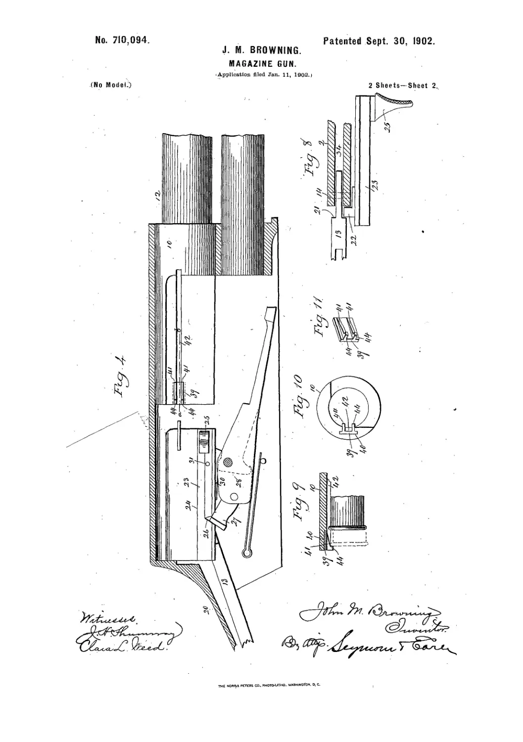


Text
J. M. BROWNING.
Breech-Loading Fire-Arm.
No. 220,271.
Patented Oct. 7, 1879.
United States Patent Office
_•_________
JOHN M. BROWNING, OF OGDEN CITY, UTAH TERRITORY.
IMPROVEMENT IN BREECH-LOADING FIRE-ARMS.
Specification forming part of Letters Patent No. 220,271, dated October 7, 1879.; application filed
May 18, 1879.
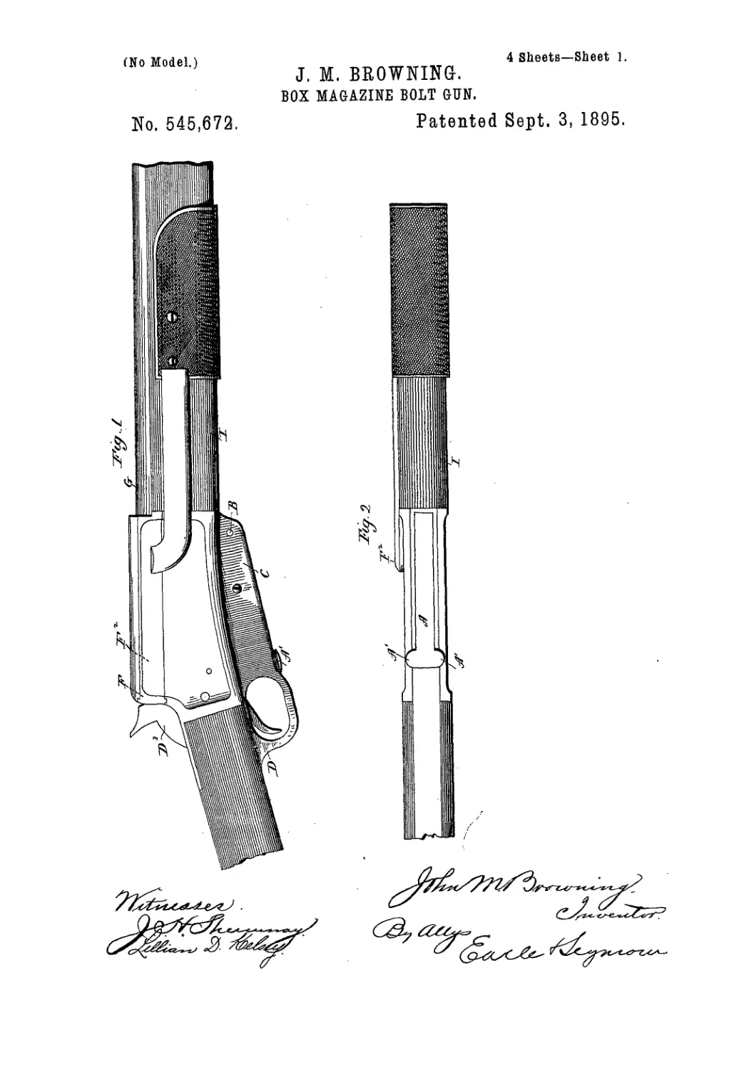
To all whom it may concern:
Be it known that I, John M. Browning, of
Ogden City, Utah Territory, have invented an
Improvement in Breech-Loading Fire-Arms,
of which the following is a specification.
My invention relates to breech-loading fire-
arms, and consists in certain details of con-
struction, hereinafter fully described and par-
ticularly indicated in the claims, whereby the
operating parts are greatly simplified and ren-
dered more durable and certain in their oper-
ation.
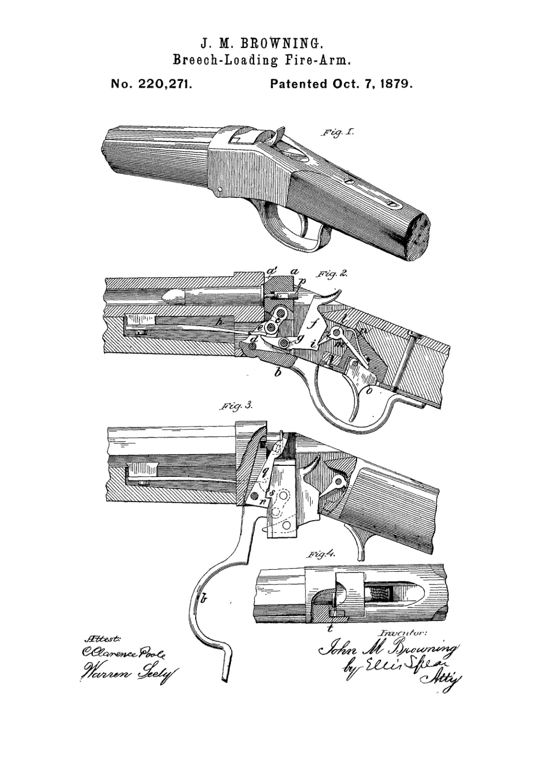
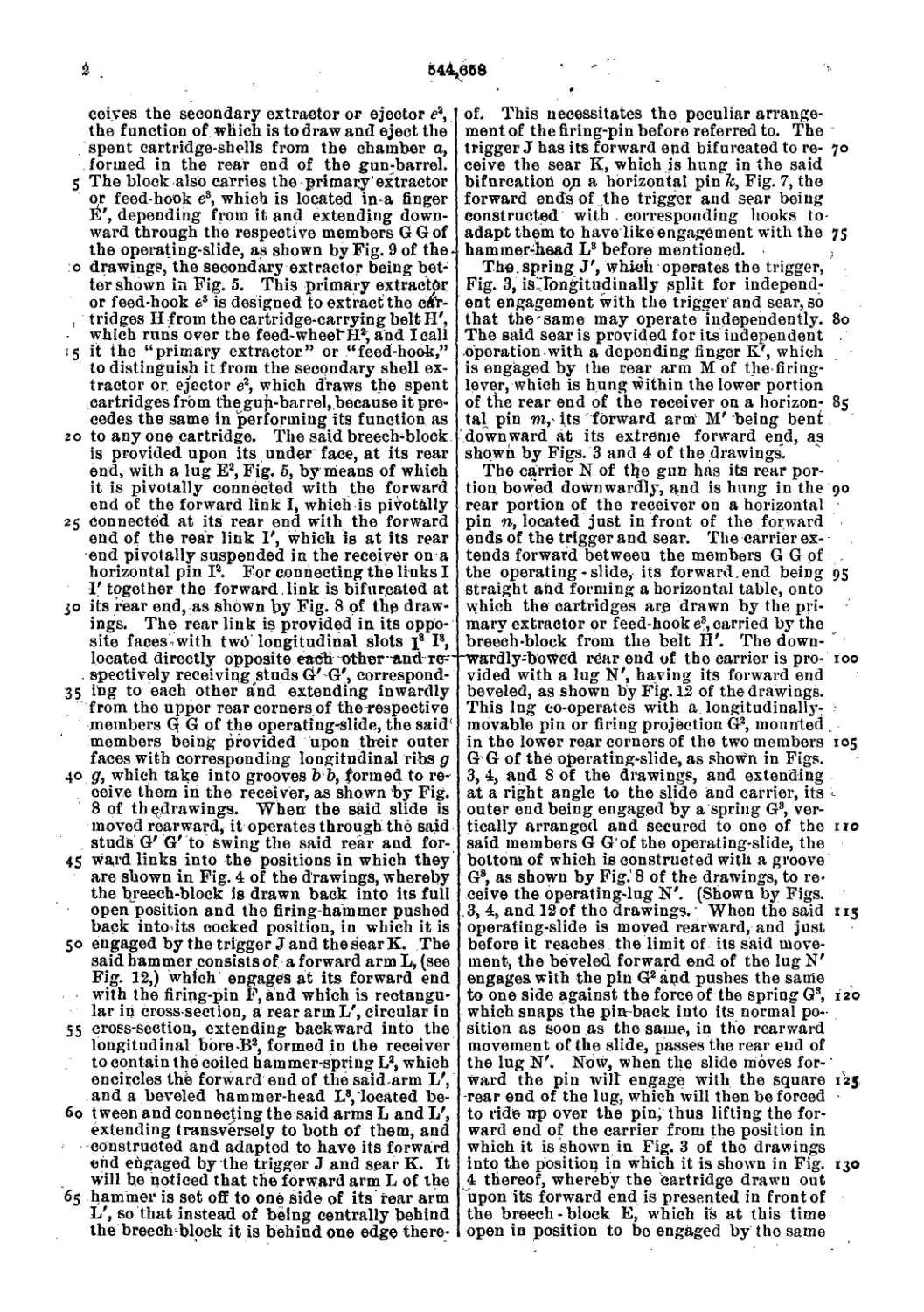
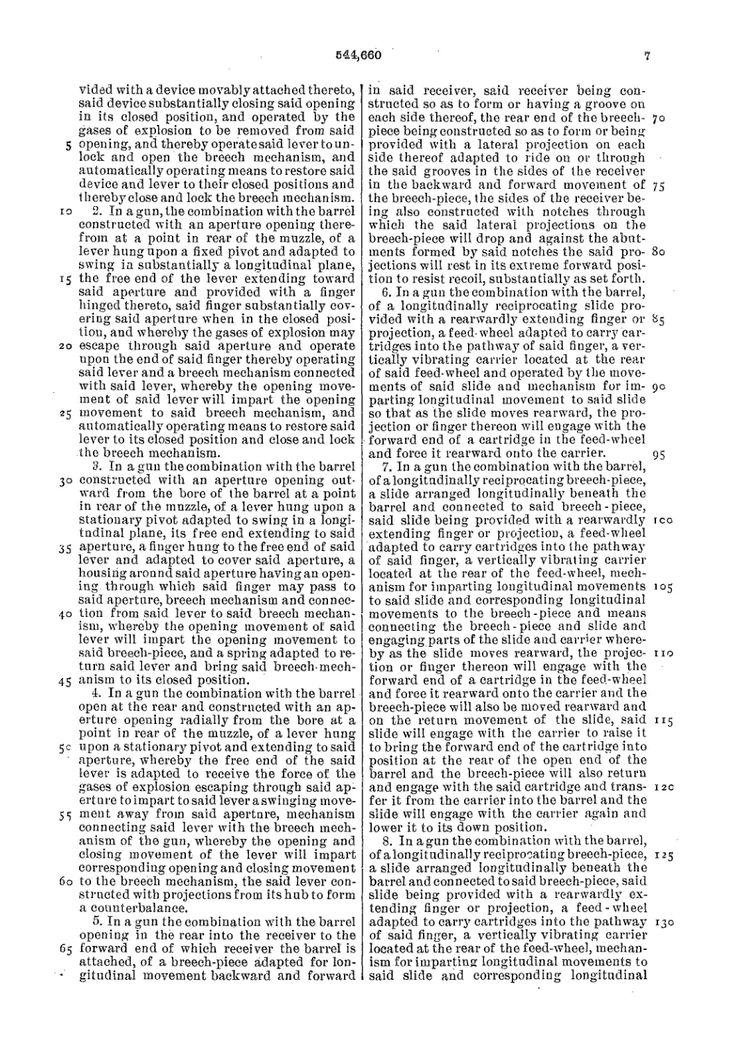
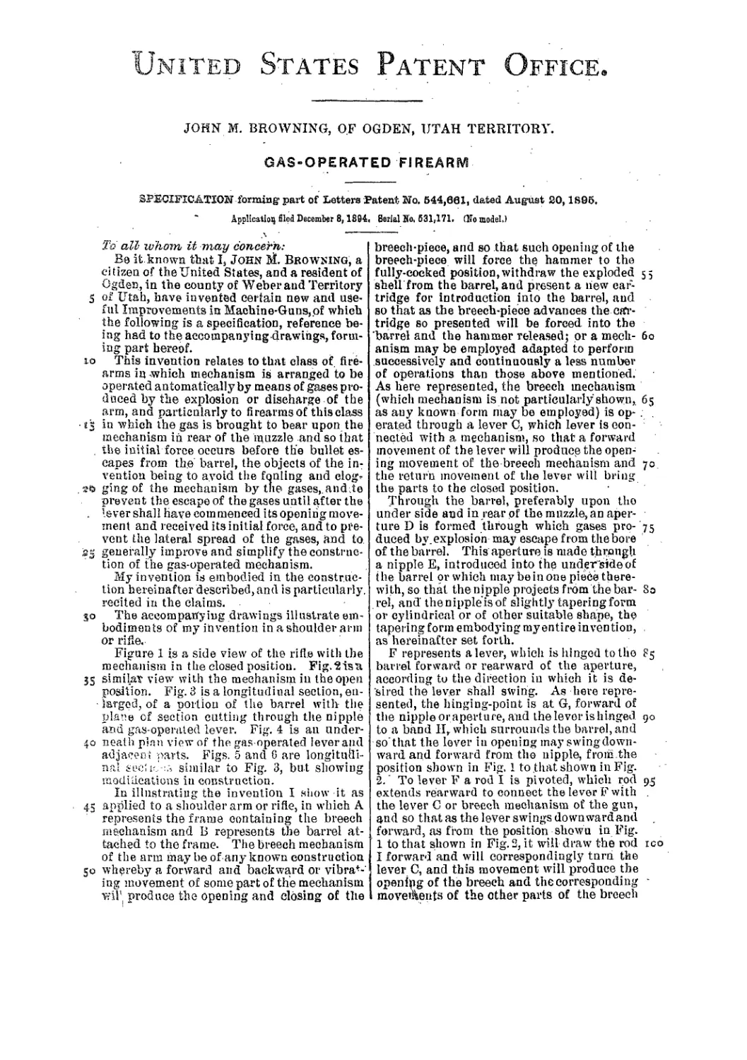
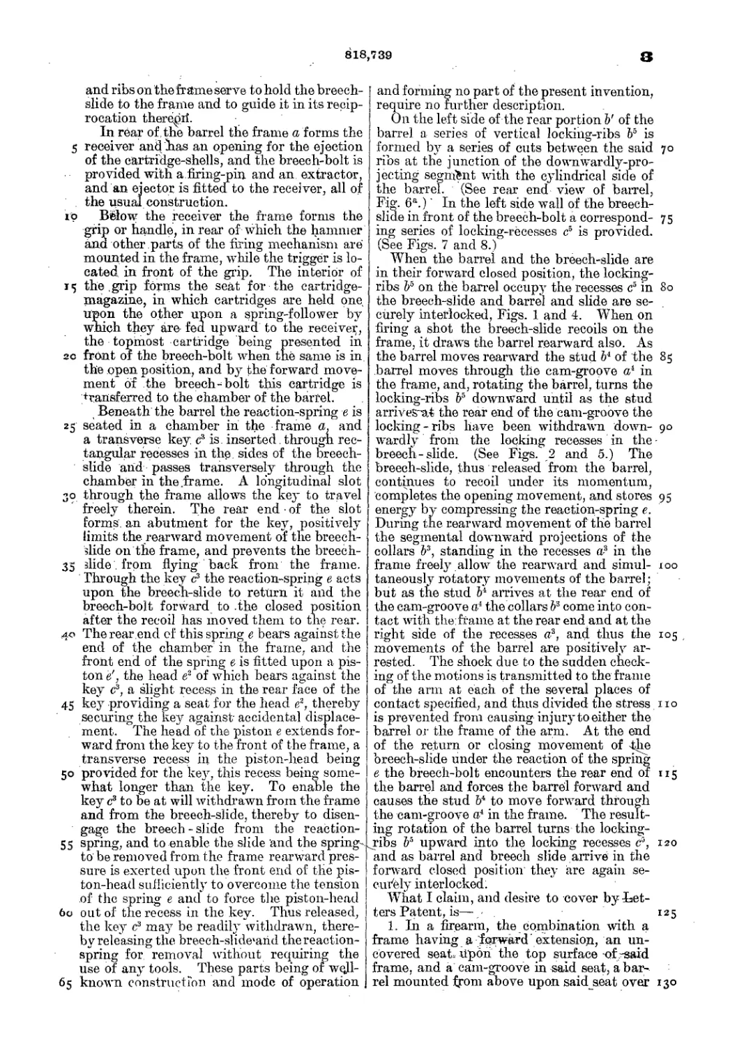
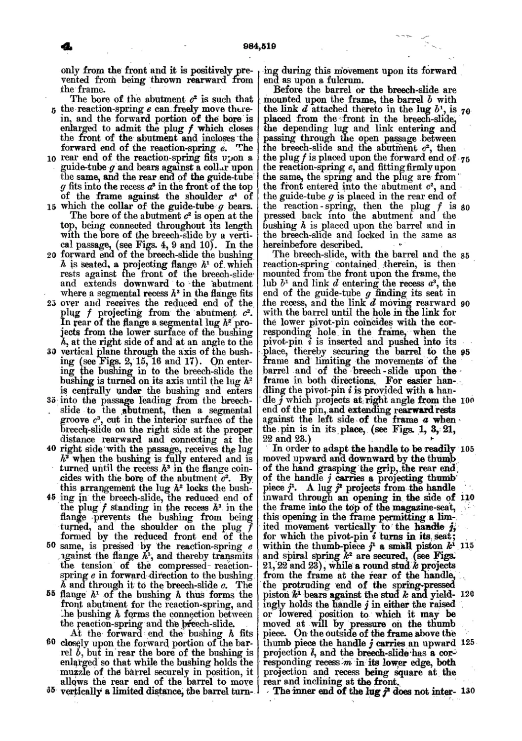
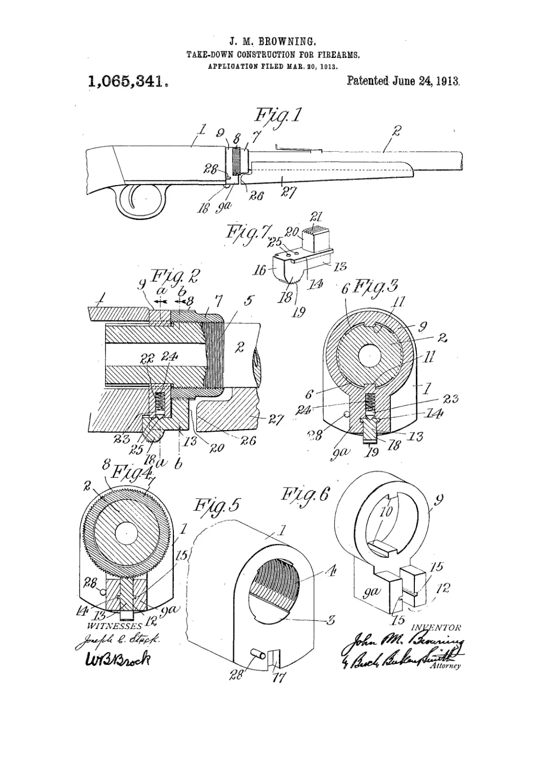
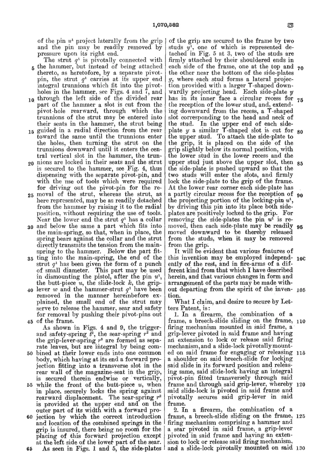
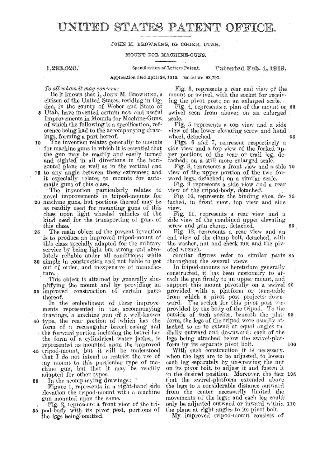
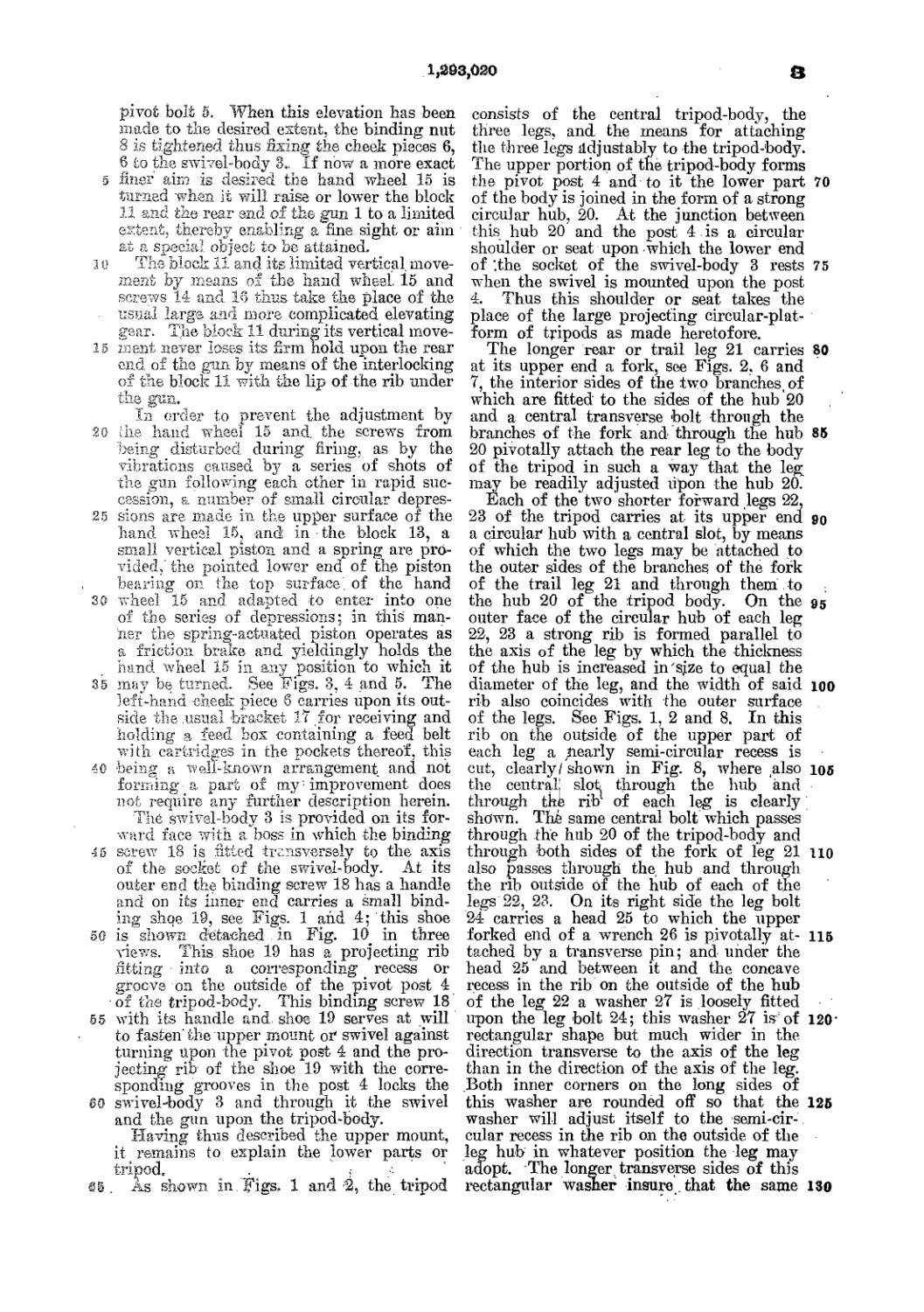
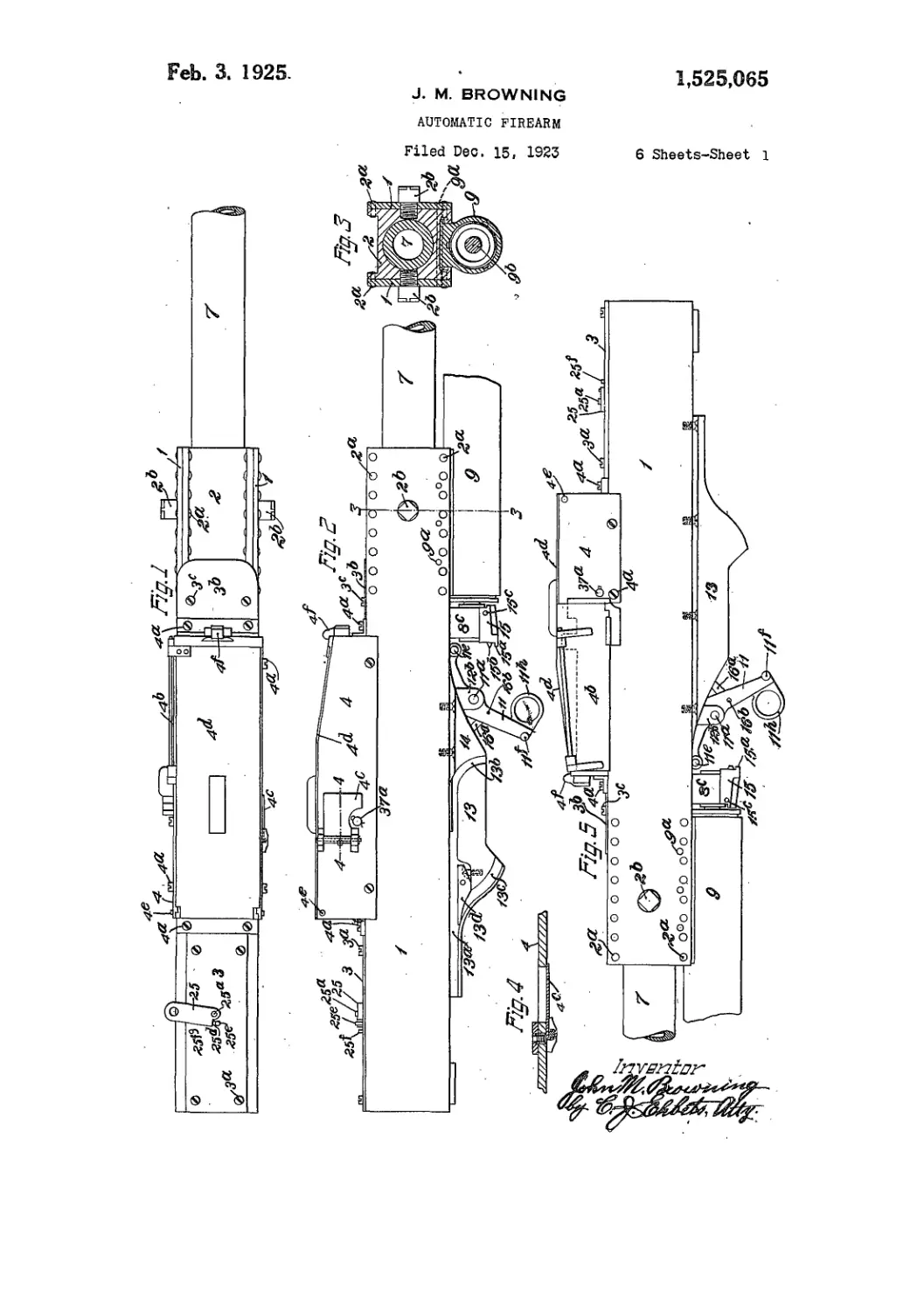
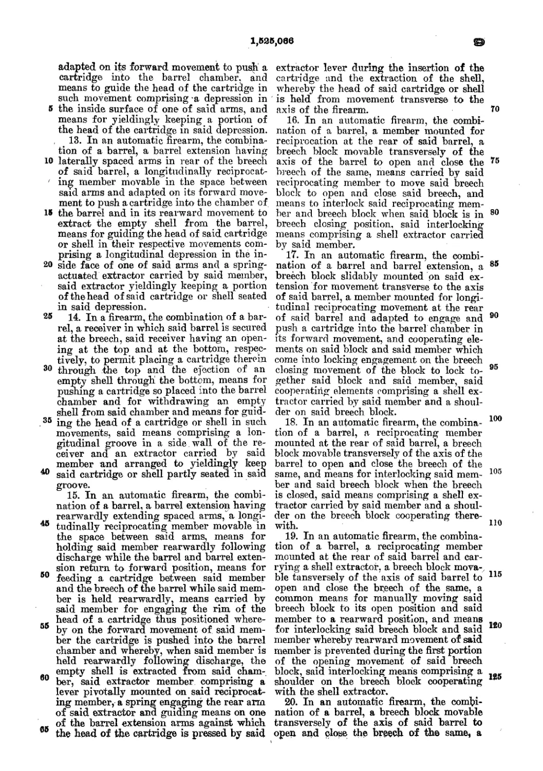
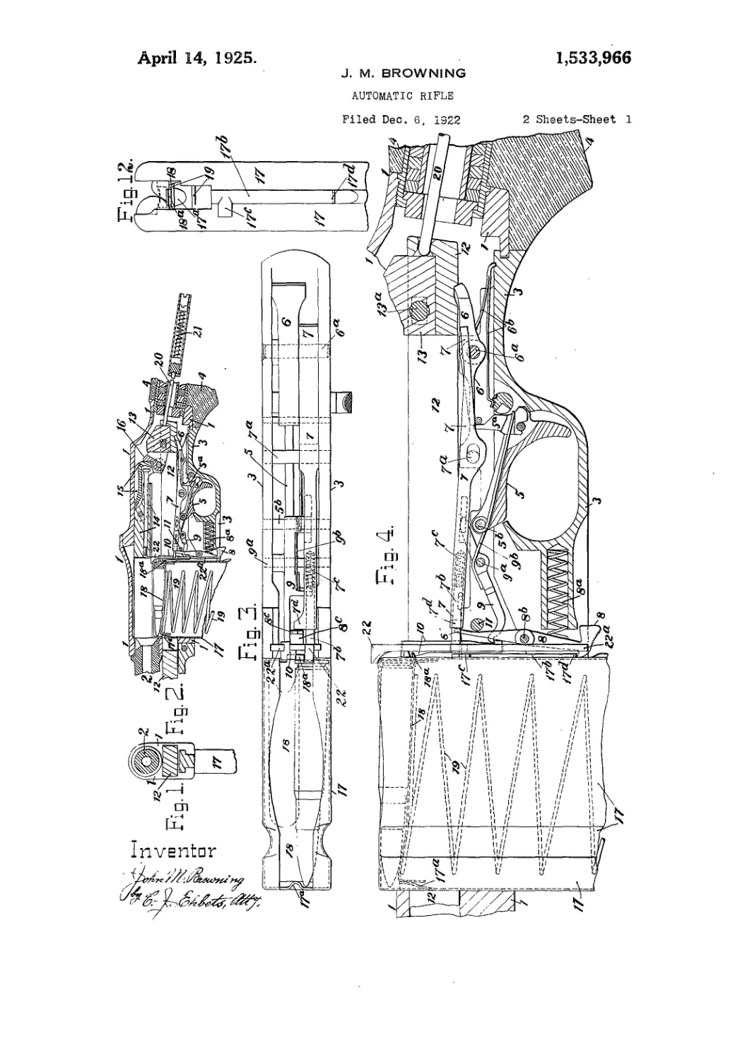
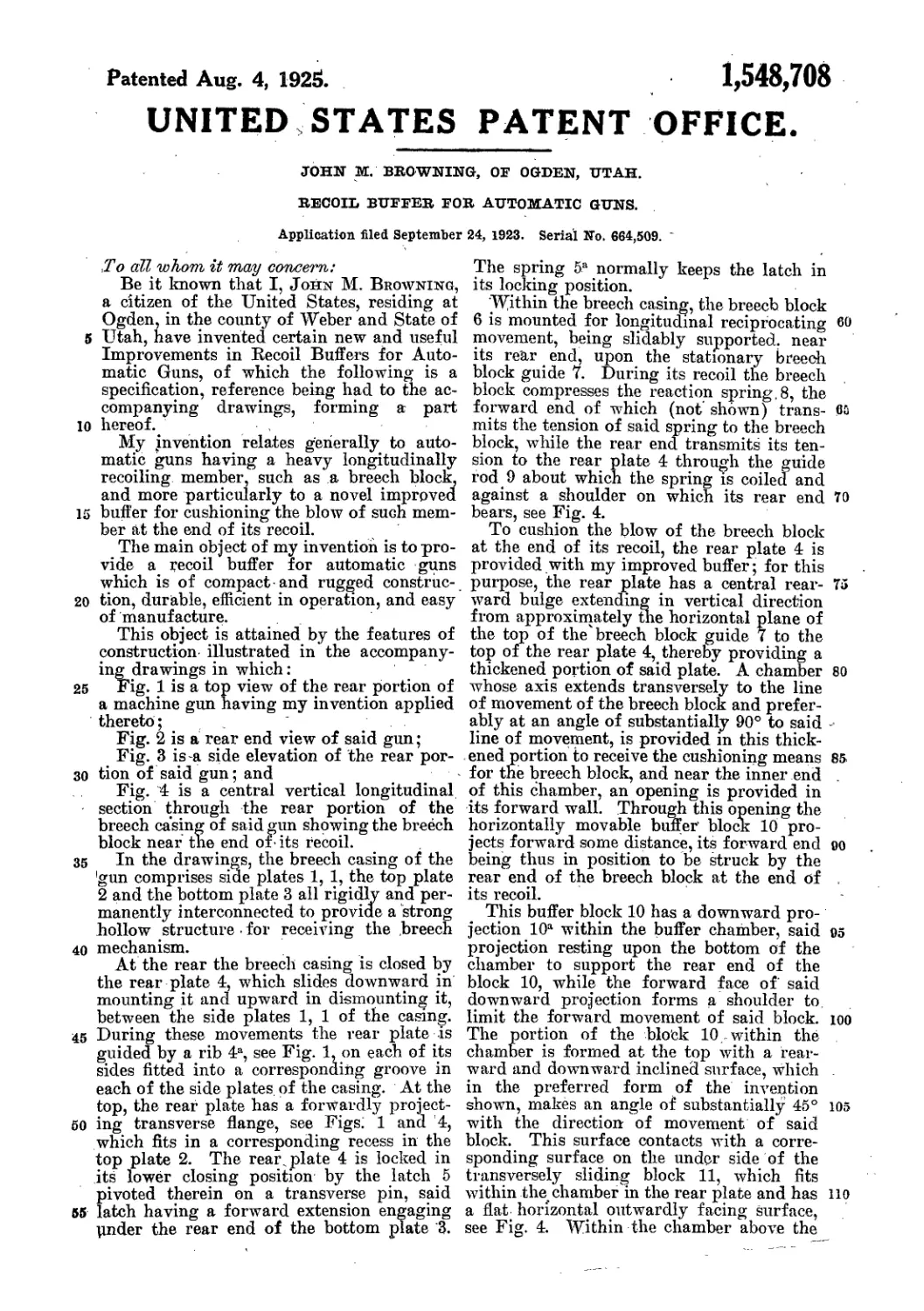
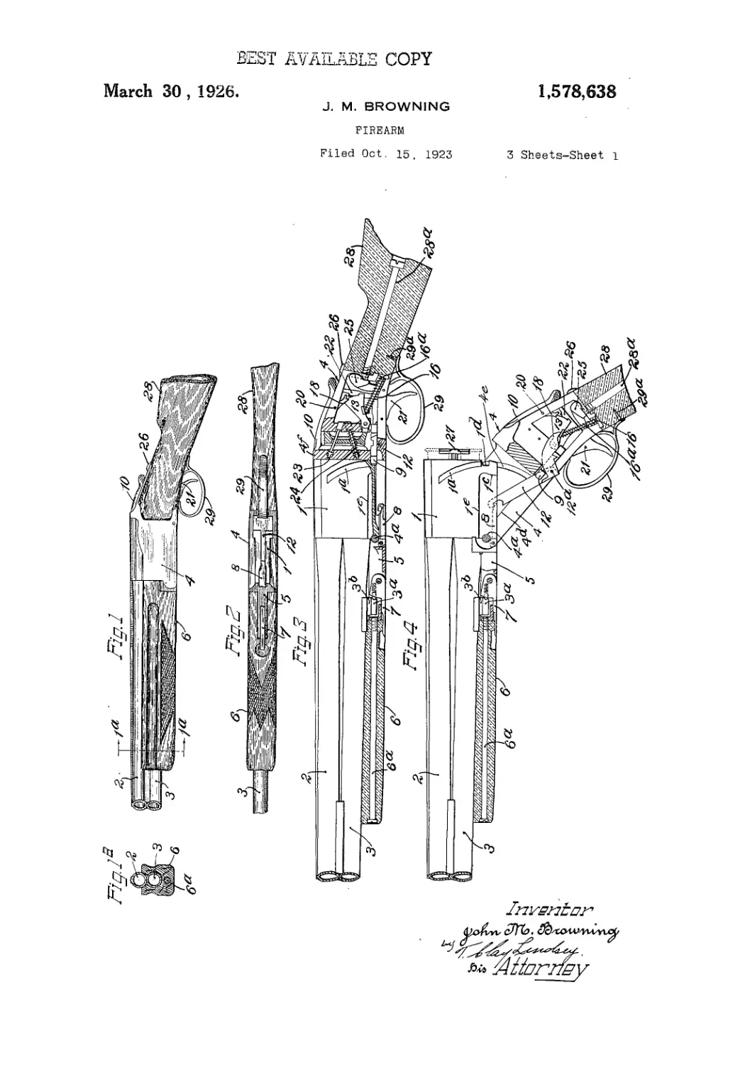
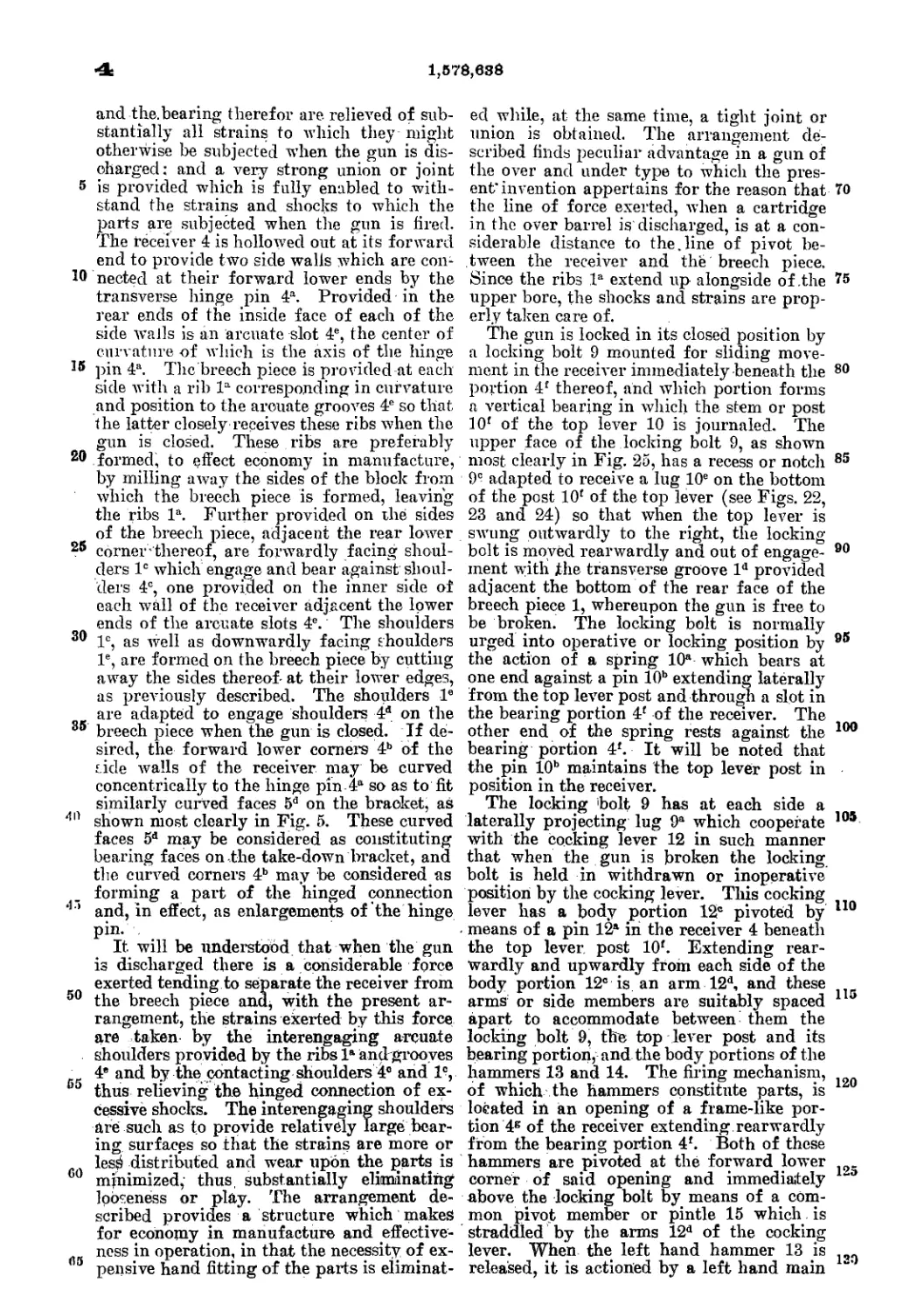
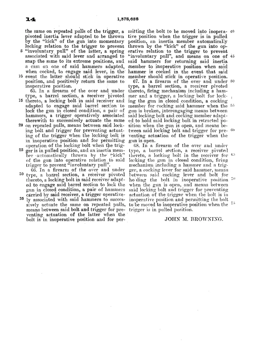
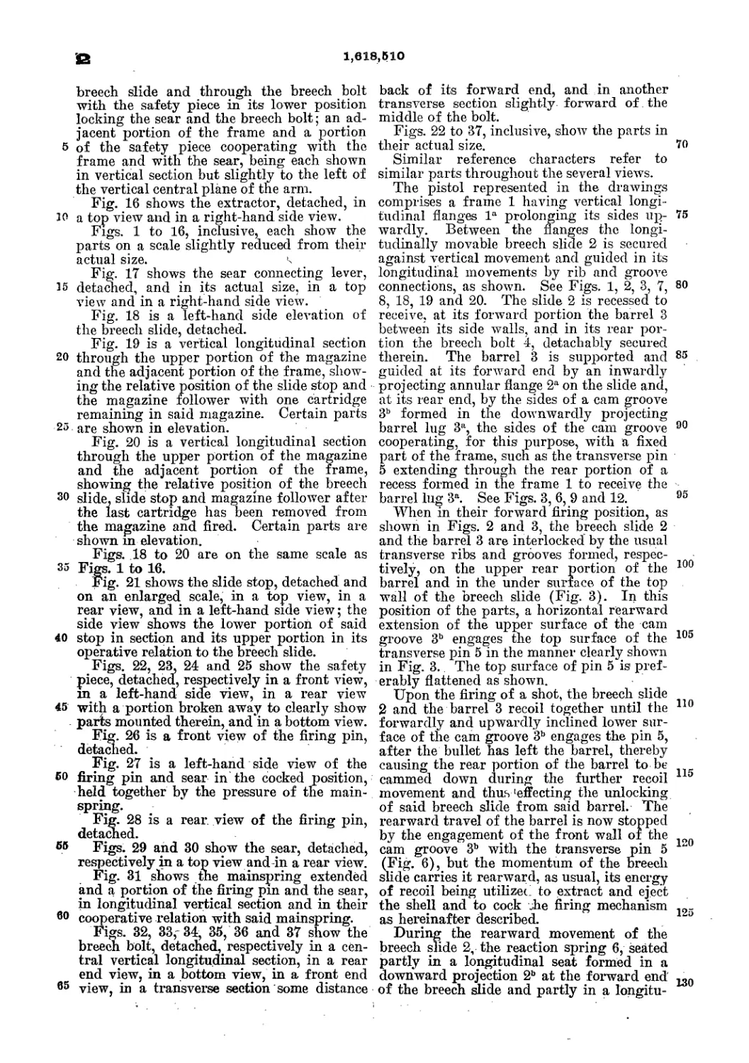
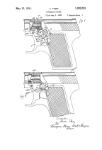
In the drawings, Figure 1 represents a per-
spective view of the breech and a part of the
stock of my improved gun. Fig. 2'represents
a longitudinal vertical section of Fig. 1, some
of the parts being shown in side elevation.
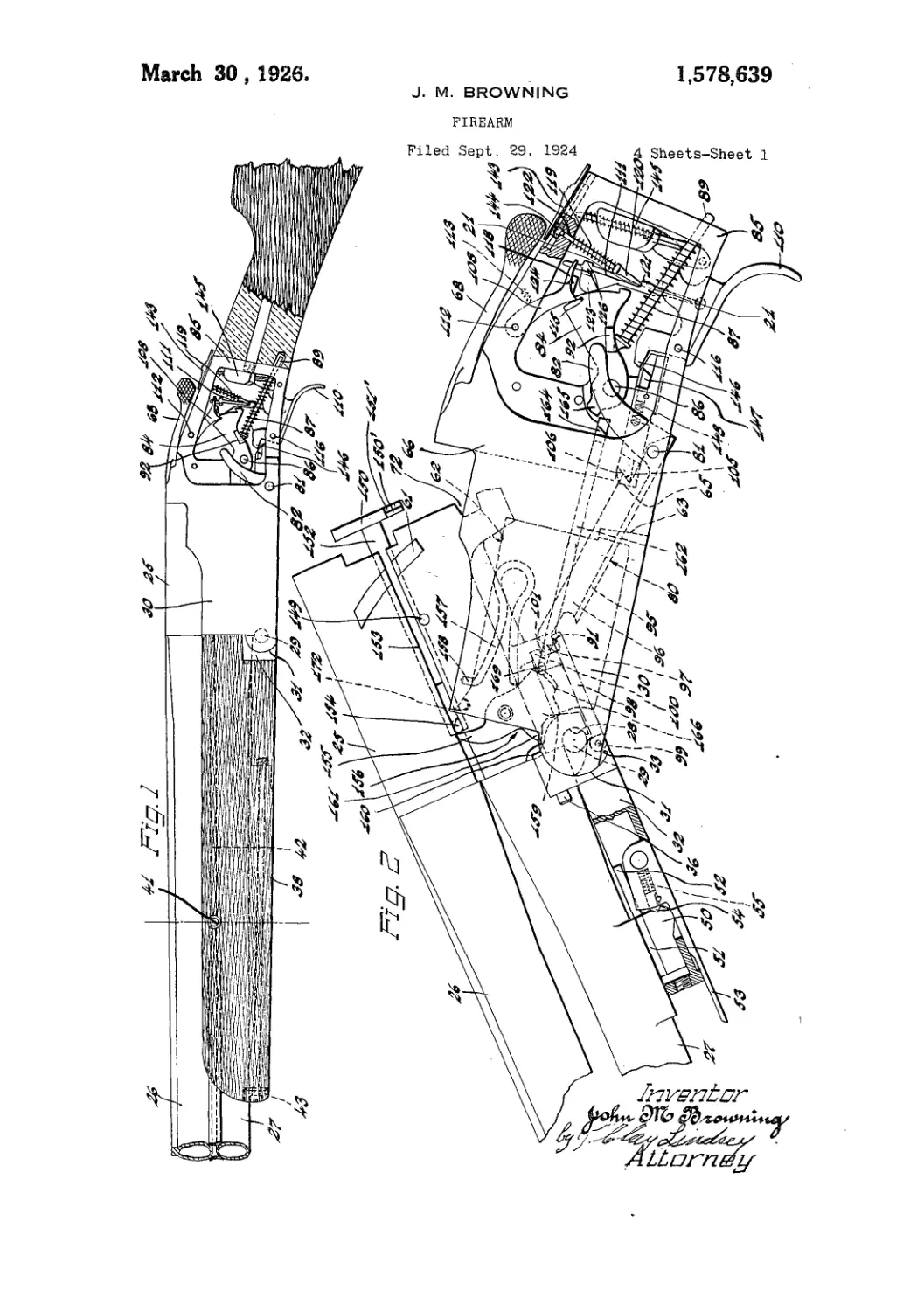
Fig. 3 is a side elevation, the case being partly
broken away to show the interior mechanism.
Fig. 4 is w top view, some of ’the parts being
broken away to show the position of the car-
tridge in place and the retractor.
My invention relates particularly to that
.class of breech-loading fire-arms in which the
breech is closed by a vertically-sliding block
operated, by the gnard-lever, and carrying the
hammer With it in its motion 'up and down.
The breeeli-block a slides vertically within
the breech-piece, to which it fits closely, and
against which it bears both in front and rear,
so that when it is raised it effectually and se-
curely closes the breech of the'gnn. This
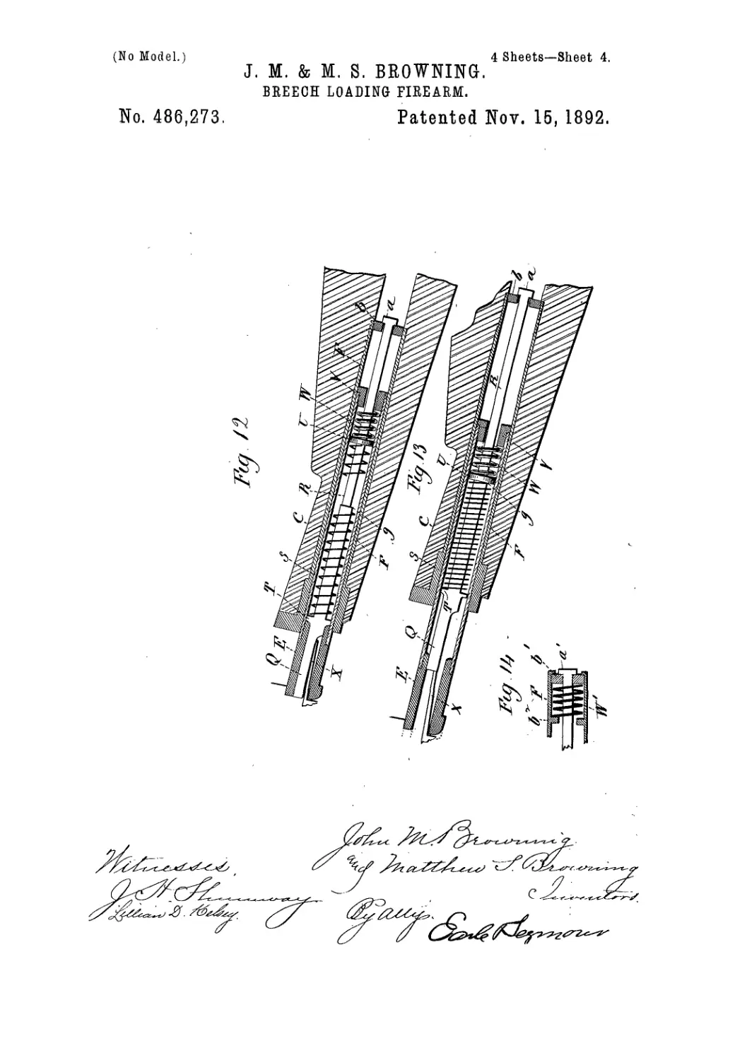
breech-piece is moved by the guard-lever Ъ, to
which it is connected by the link c, within the
slot in the interior of the block. The guard-
lever Ъ is pivoted to the breech-frame at d,
-slightly in front of the breech - block. The
guard is also formed with lugs e e, adapted to
fit into the slotted breech-block and to receive
between them the link c, to which they are.
connected by a pin at a point within the slot
when the guard is brought into a position for
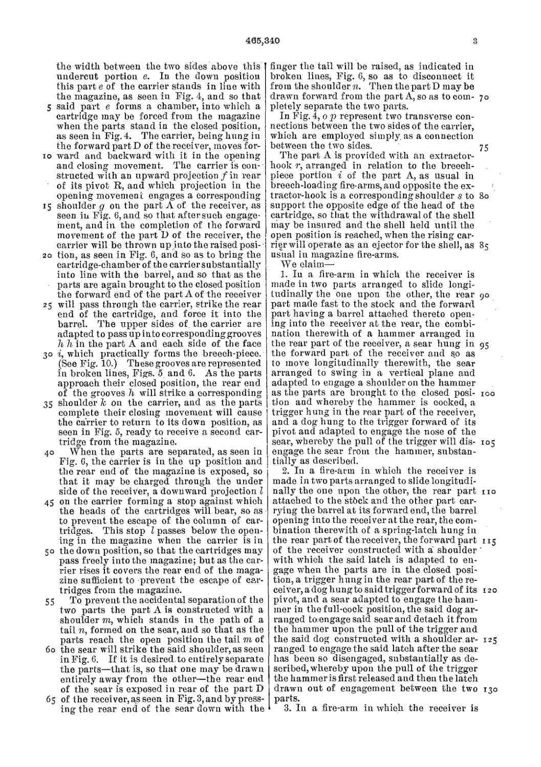
firing. The guard-lever is also so constructed
that when it is brought into the position last
specified it effectually closes the opening
through which the block and the hammer
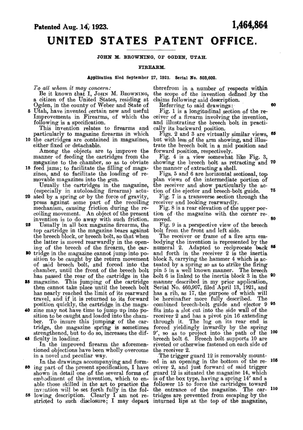
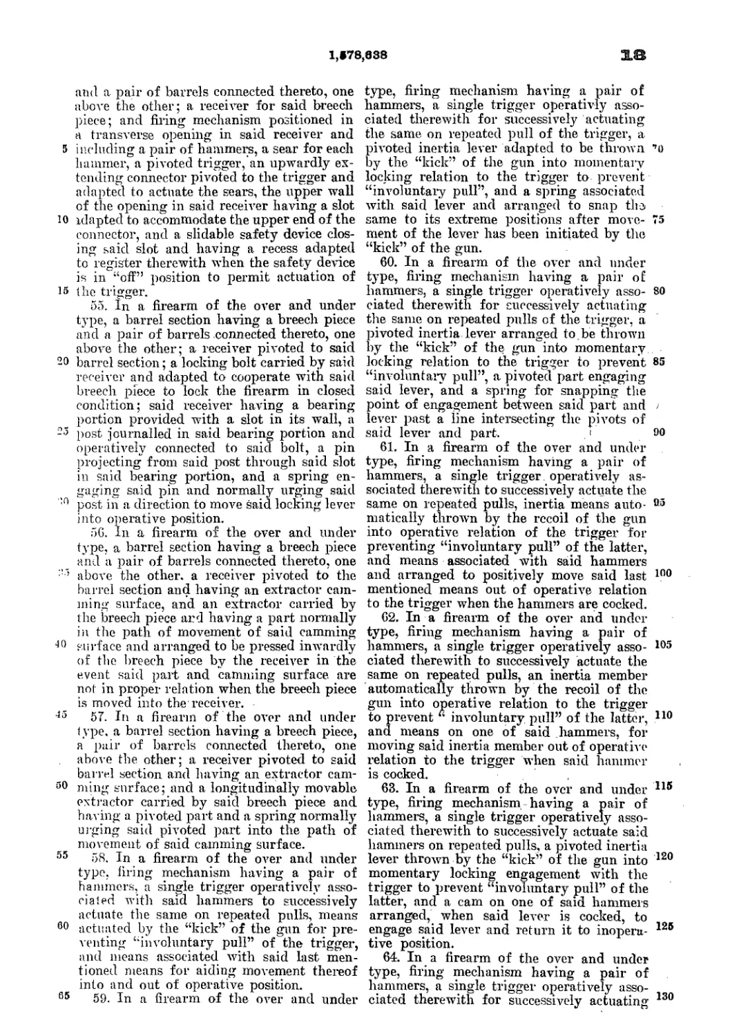
move when the lever is depressed, as in open-
ing the breech.
The hammer f is pivoted to the block at g,
within the slot of said block. The tail of the
hammer extends -through the slot and rests,
when the block is raised, under the end of the
spring h, which is secured to the barrel, as
shown in Figs. 2 and 3.
The breech-piece is slotted to the rear suffi-
ciently to give space for the hammer when at
fnll-cock. The hammer is constructed with
an offset at i, against which the dog fc bears,
when the breech-block is raised, to close the
breech. This dog is pivoted at I, and is pro-
vided with an arm, m, andspring n, the latter
bearing against the shell in the breech-frame,
so as to keep the arm m pressed down against
the trigger o. The pressure of the spring n
keeps the end of the dog fc against the rear
edge of the hammer, whether the breech-block
be raised, as shown in Fig. 2, or lowered, as
shown in Fig. 3. ' When the guard Ъ is de-
pressed for the purpose of opening the breech
of the gun, by means of the links e it draws
down the breech-block, carrying with it the
hammer /, the hammer being thrown forward
in its passage, and the tail of it dropping from
contact with the spring h. When the lever is
elevated its return movement lifts the breech-
block, and with it the hammer; but as the dog
1c comes in contact with the offset i the rear
part of the hammer is arrested in its move-
ment and held in place while the forward part
continues to rise, being carried upward by the
continued movement of the lever Ъ, sb that
the hammer is thrown back by the completion
of the movement and held at full-cock, rest-
ing over the point and on the breech-piece,
while in the latter part of the movement the
tail of the hammer has come in contact with
the spring h, and lifted it sufficiently to bring
the strain of the spring npon the tail of the
hammer, so as to give, a snitable blow upon
the firing-pin.
The breech-block is supported when the
guard-lever is closed by means of the links
and lugs e e, the pivot-pin which connects the
said link and lugs being carried into line with
the other link-pin and pivot of the guard-lever,
or slightly past the dead-point, so as to se-
curely lock the block in closed position.
The firing-pin is of the ordinary construc-
tion, and is represented at p. Ti c retractor
is shown at q. It is pivoted at the lower left-
г
220,271
hand corner in a slot in the breech-piece, and
rests in a recess ent in one side of the breech-
block. The shape of the retractor is shown
in Fig. 3. At the lower end it has an offset,
r, which projects into a groove in the lower
part of the breech-block. A projection, s, on
the breech-block extending across the upper
end of this lower slot strikes the offset r upon
the lower end of the retractor when the block
is near the limit of its downward motion, and
throws the upper end of the retractor back,
thus ejecting the empty shell. A stnd project-
ing inwardly upon the retractor, as shown at
Л Fig. 4, rests beneath the flange of the shell,
so as to obtain a suitable hold and allow the
retractor in its motion to throw out the shell.
The retractor extends upward through its re-
cess in the breech-piece, and the upper end of
it is flush with the surface of the latter. This
effectually closes the slot in the breech-block
against the admission of dirt or anything
which might clog the block. The breech-block
is bevpled atin order to push home the car-
tridge in case it should happen not to be suffi-
ciently pushed forward into its place when
the block rises.
I am aware that a breech-block carrying a
hammer pivoted upon the block and cocked
by upward motion of the said block, in con-
nection with the trigger, is not new.
"What I claim as my invention, and desire
to secure by Letters Patent of the United
States, is—
1. In“a breech-loading fire-arm, the combi-
nation of the slotted breech-block and of the
hammer pivoted within the slot with the
spring in front of the block, projecting be
tween the lugs e e of the gnard-lever and bear-
ing upon the tail of the hammer, and with
the link c, connecting the block and guard-
lever, as set forth. '
2. The combination of the slotted breech-
block, the lugs e e, the link c, and the ham-
mer f, pivoted at g, and extending between
the lugs c, to bear against the spring h, as and
for the purposes set forth.
3. The dog 7c, provided with the arm m, nest-
ing on the trigger'^ and with the spring n, op-
erating in connection with the rear of the
hammer and the offset i, and with the breech-
block and spring //, as and for the purpose set
forth.
In testimony whereof I have signed my
name to this specification in the presence of
two subscribing witnesses.
JOHN M. BEOWNING.
Witnesses:
Jonathan Browning,
0. F. Middlet'on.
J. M. & M. S. BROWNING.
CARTRIDGE LOADING IMPLEMENT.
(No Model.)
IS PETER5. Pliolo utlrognpher Washmbtoi D C
United States Patent Office.
JOHN M. BEOWNING AND MATTHEW S. BEOWNING, OE OGDEN, UTAH
TEEEITOEY.
CARTRIDGE-LOADING IMPLEMENT.
SPECIFICATION forming part of Letters Patent No. 247,881, dated October 4, 1881.
Application filed August 2,1881 (No model.)
To all whom it may concern:
Be it known that we, John M. Browning
and Matthew S. Browning, of Ogden, in
the county of Weber and Territory of Utah,
5 have invented a new and useful Improvement
in Cartridge-Loading Implements; and we do
hereby declare that the following is a full, clear,
and exact description of the same.
Our invention is a combined reloading-tool
io for gun-cartridges.
The object of the invention is to provide in
a single tool all the appliances necessary for
use in the loading or reloading of cartridges,
and in the steps necessary for the preparation
15 of the shell for reloading.
Our invention consists, therefore, first, of a
combined tool which includes, by reason of its
peculiar construction, mechanism for seating
the ball, for decapping any kind of shell using
20 a cap, mechanism for capping the shell, a ball-
mold, and a wad-punch.
It consists,further, in an improved construc-
tion of ball-seating device; and, finally, in com-
, bining, with this improved form of bullet-seat-
25 ing device, the various other devices above
specified.
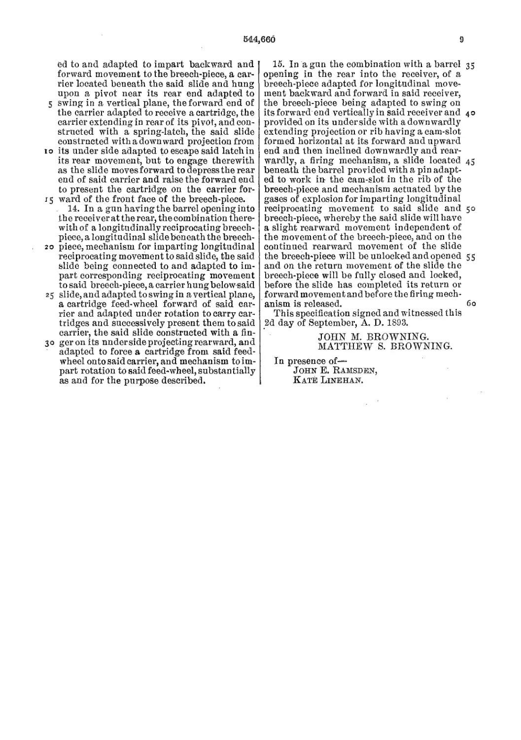
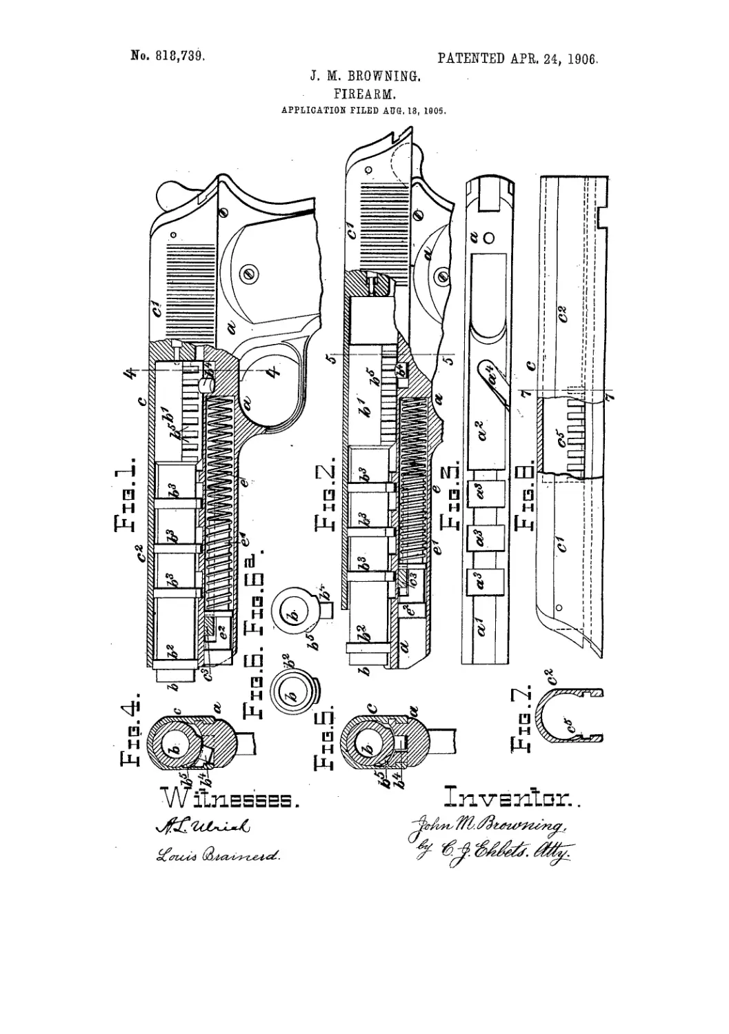
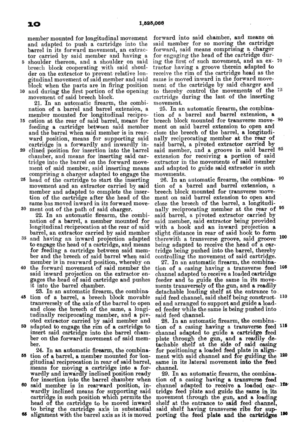
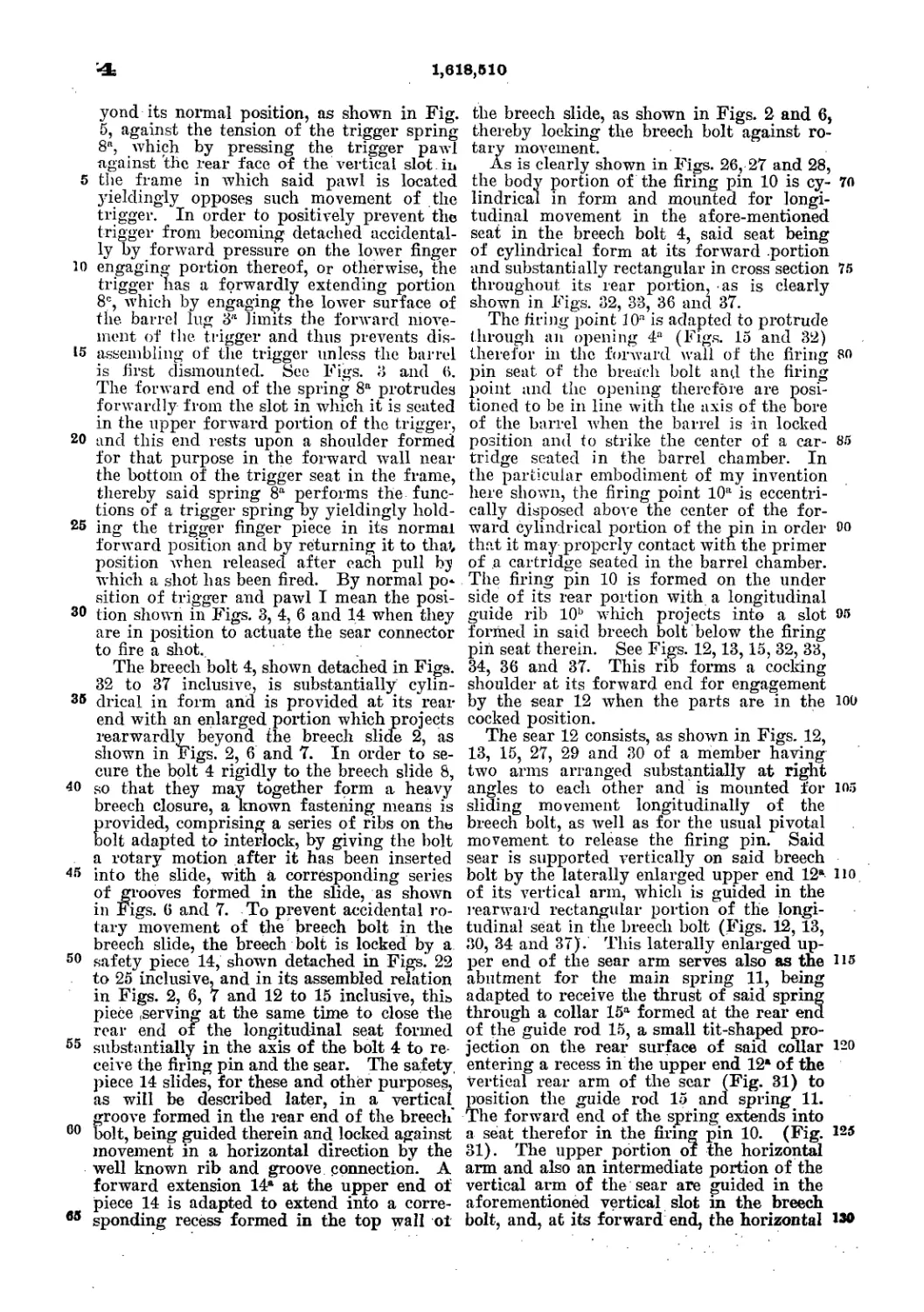
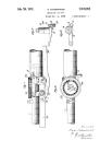
In the accompanying drawings, Figure 1
shows a side elevation of our improved tool.
Fig. 2 shows a central longitudinal section of
30 the same, taken iu the plane of the handles.
Fig. 3 represents the tool as open for seating
the bullet. Fig. 4 shows detached view of
spindle.
In the drawings, A В represent the two main
35 parts of the tool. These have similar handles,
a a, and they are connected together by a piv-
otal bolt, which passes through lugs b b on the
part A, and the disk c on the part B, which
disk fits snngly between said lugs.
40 In connection with the parts already named,
we will first describe that part of the device
which is adapted to seat the bullet and to re-
move the cap when the shell has a single fire-
vent.
45 The cylindrical body of the part A is bored
out or otherwise formed with an axial circular
chamber in length equal to the length of the
cartridge to be loaded with the ball inserted,
and of a size of bore adapted to receive such
50 cartridge. A shoulder, d, is formed on the
disk shaped head of the part B, arranged to
overhang and press upon the inserted car-
tridge when the handles a a are open. The
position of this shoulder oroffsetis soarranged
that the ball may be dropped into the bottom 55
of the chamber in A and the shell placed upon
it, or the ball may be slightly entered in the
shell and both together placed in the chamber,
when the handles are closed; and then, the
handles being opened, the shonlder d will force 60
the shell down upon the ball, firmly seating
the same. In order to retract the cartridge
or shell, a second shoulder or offset, c, is pro-
vided below the one first named, and adapted -
to come up under the rim or flange of the shell, 65
when the handles are closing, and to draw it
partly out from the chamber. This construc-
tion is sufficient for seating the ball, and by
reason of the axial chamber the construction
is in a very compact and safe form. This con- 70
struetion, however, may also be used iu con-
nection with another device for removing the
caps from shells which have been fired, when
such shells are made with a central vent. For
this purpose a spindle, /, (shown detached in 75
Fig. 4,) is made of a length equal to, or slightly
greater than, the length of the chamber, and
is provided with a pin, g, adapted to enter the
central perforation in the head of the cartridge.
This spindle is dropped into the chamber. The 80
empty shell is placed upon it and pressed down
by the opening of the handles, in the same
manner as forcing the shell upon the ball. As
the shell is forced down the pin g enters the
vent and pushes off the cap. A small recess, 85
1, is made in the face of the shoulder or off-
set d, to allow the cap to rise.
For cartridges which have more than one
fire-vent we have provided another device in
the same tool. This consists of an awl, i,hav- 90
ing a threaded shank, which screws through
the flanged side of the part B. Its point pro-
jects opposite a rounded seat, k, on the part
A, near the inner edge of said seat, as shown
more clearly iu Fig. 1. In order to remove a 95
cap by this device the head of the shell is laid
in the seat, the face thereof being presented
in an inclined position toward the point of the
awl. The handles are then closed, which brings
the awl into the hammer-dent in the cap, and 100
2
347, SSI
the parts being held in that position the cap
is removed by raising the mnzzle of the shell.
The wad-cutting device is shown at I m. m
is a perforation through the part B, in (pref-
5 erably) the center, and in the plane in which
thehandlesopen. Its diameter is equal to that
of the wads to be ent. Directly opposite this,
and placed so as to enter it when the handles
are closed, is a stud, Z, having a plain face and
ro sharp edge, so that when pasteboard or other
suitable material is placed upon the inner plain
face, o, of the part B,over the opening m, and
the handles closed, the stud I forces the disk
out of the board into the perforation, thus per-
15 forming the operation of cutting the wad. In
the same part В is another similar perforation,
p, made larger to receive the cartridge which
is to be capped. A small stud, q, set in the
part A so as to come against the cap in the
20 center of the shell, when in place, is provided
for pressing on the cap. These devices for cut-
ting the wad and setting the cap we are aware
are not new in themselves, but are only new in
their relation to the general construction of
25 the tool, whereby they are combined to form
one tool of an improved and more convenient
shape.
Another old feature, but in the same manner
newly combined, is the ball-mold r, formed in
_4°-the two sides A and B, near the pivoted ends.
The cover consists of the piece s, pivoted on
the part A, to which it is fitted and held in po-
sition within suitable limits by means of a pin,
2, projecting into a curved slot, 3,iu the piece
35 s. Thisslotallowssnfficientmovement,sothat
when the pin is at one end the hole 4 is di-
rectly over the ball-mold, but when the piece
8 is moved to the other side the cover cuts off
the neck of the ball and leaves it ready for in-
40 sertion into the shell. The pin 2 may be a
prolongation of the pivotal pin which holds
the two parts together.
It will be seen, therefore, that all the neces-
sary parts are combined in this one tool. The
centralperforation does away with projections, 45
brings the parts into the least possible space,
and renders it possible to make the tool serve
for the shortest or longest cartridges without
any difference in its outside shape.
The main parts of the tool may all be cast, 50
and are very easily fitted, so that the tool may
be cheaply made, and combines in itself all
that is necessary for the general purpose for
which it is intended.
Having thus described our invention, what 55
we claim is—
1. A tool for seating balls, consisting of the
part A, having an axial chamber, in combina-
tion with a part, B, pivoted to the part A by
means of the head fitted between lugs on said 60
part A, the said head being provided with a
shoulder, d, adapted to force the shell into the
chamber by the opening of the two parts, sub-
stantially as described.
2. The combination of the part A, axially 65
chambered, the part B, pivoted thereto, as
shown, and provided with a shoulder, d, and
a retractiug-shoulder, e, substantially as de-
scribed.
3. The combined tool consisting of the parts 70
A and B, the former having an axial chamber
and the latter device shonlders, as described,
operated in connection therewith, and both
formed with the described ball-mold, capping,
wad-cutting, and cap-removing devices. 75
In testimony whereof we have signed our
names to this specification in the presence of
two subscribing witnesses.
JOHN M. BROWNING.
MATTHEW S. BROWNING.
Witnesses:
Robert Middleton,
0. F. Middleton.
J. M. & M. S. BROWNING.
MAGAZINE FIRE ARM.
United States Patent Office^
JOHN M. BROWNING AND MATTHEW S. BROWNING, OF OGDEN CITY, UTAH
TERRITORY.
MAGAZINE FIRE-ARM.
SPECIFICATION forming part of Letters Patent No. 261,667, dated July 25, 1882,
Application filed March 20,1SS2. (No model.-)
Io all whom it may concern:
Be it known that we, John M. Browning
and Matthew S. Browning, of Ogden City,
in the county of Weber and Territory of Utah,
5 have invented anew and useful Improvement
in Magazine Fire-Arms; and we do hereby
declare that the following is a full, clear, and
exact description of the same.
Our invention relates to improvements in
io that class of breech-loading fire-arms in which
the cartridges are contained in a magazine lo-
cated beneath the barrel, are fed separately to a
vibrating carrier operated by a longitudinally-
sliding bolt, and are raised by the carrier to a
15 position opposite the chamber of the gun and
forced into thechamber by the forward move-
ment of the bolt.
Our invention consists mainly in improved
devices for charging the magazine through the
20 receiver; further, in the peculiar construction
of the bolt, and generally in improved details
of construction, now to be morefully described.
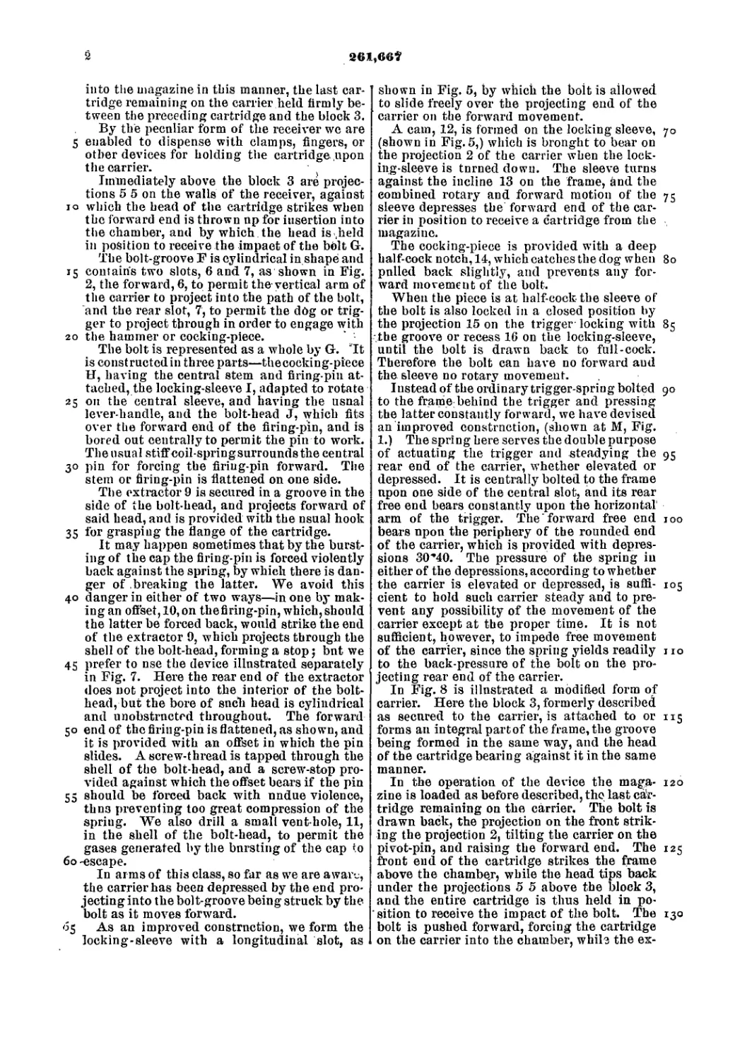
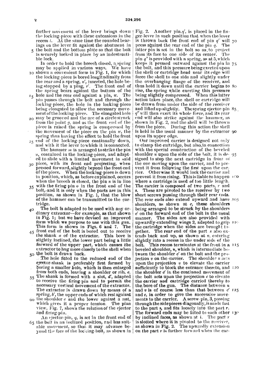
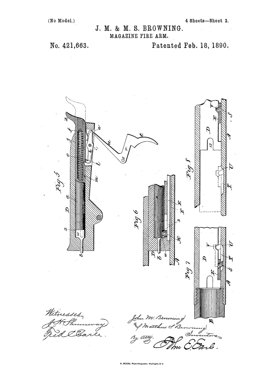
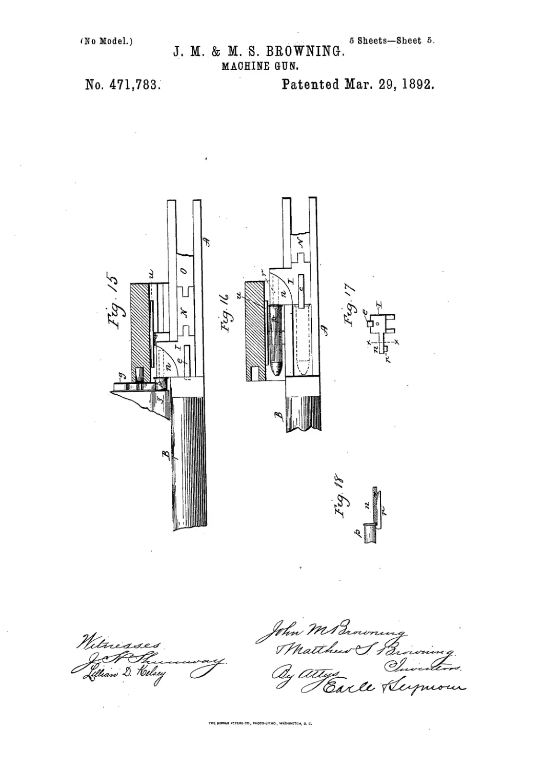
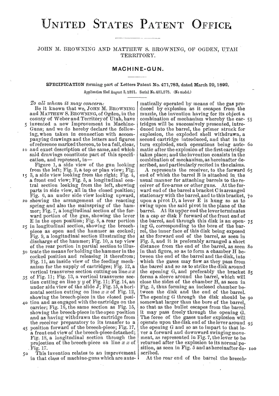
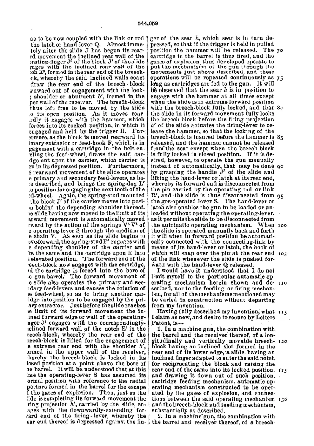
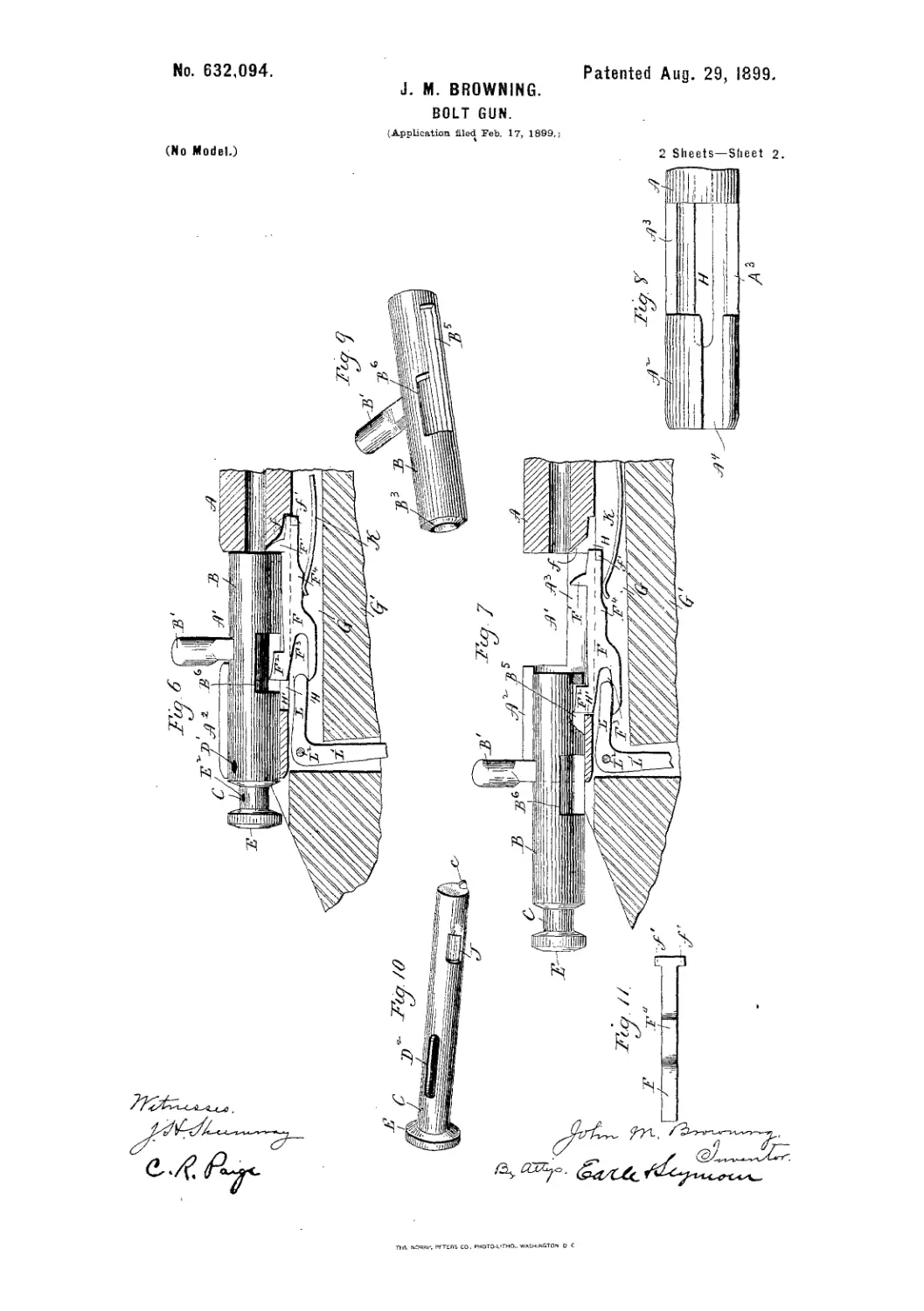
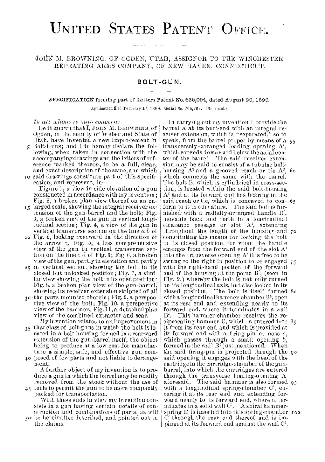
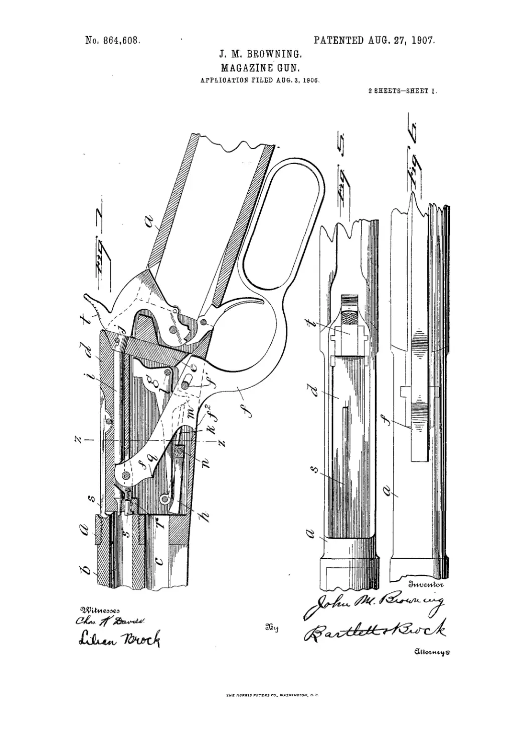
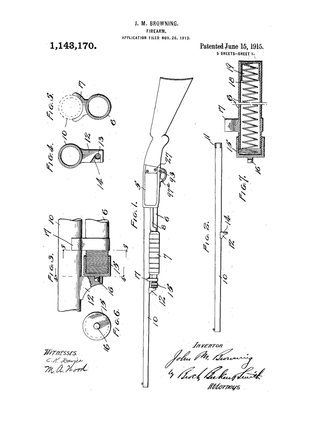
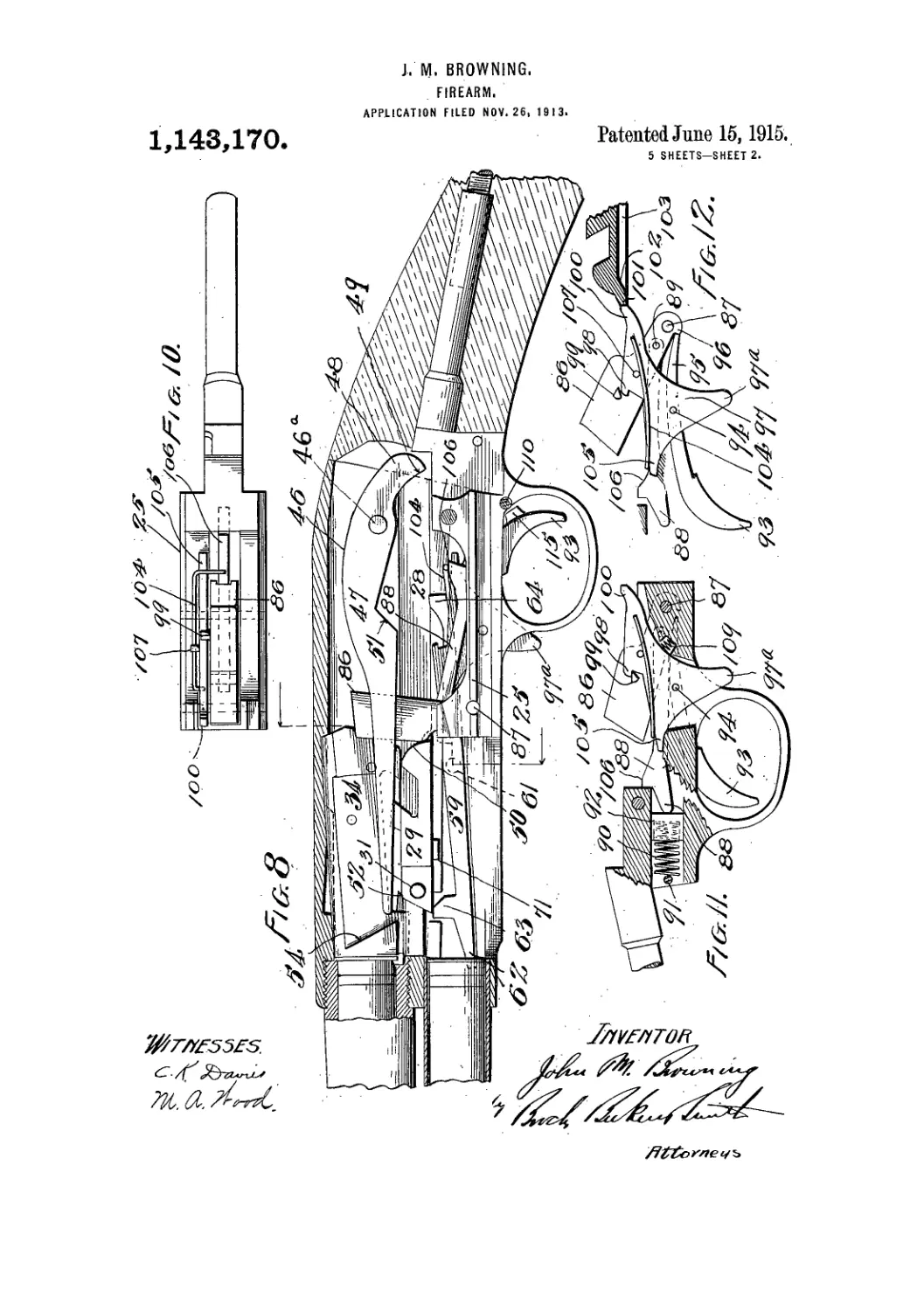
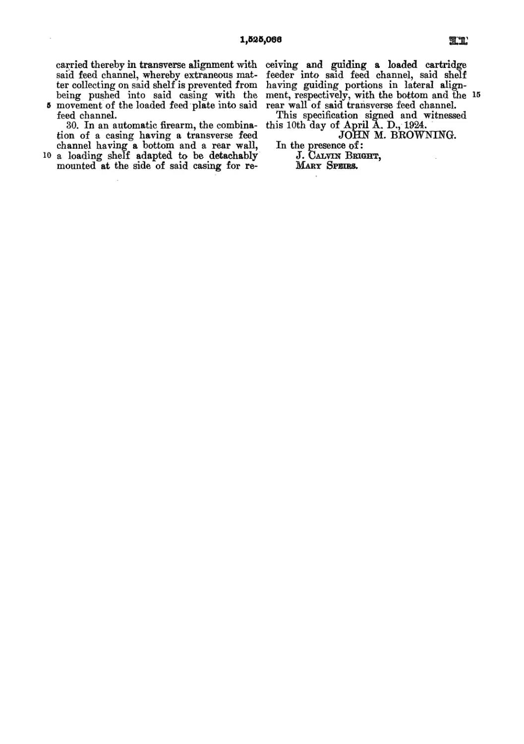
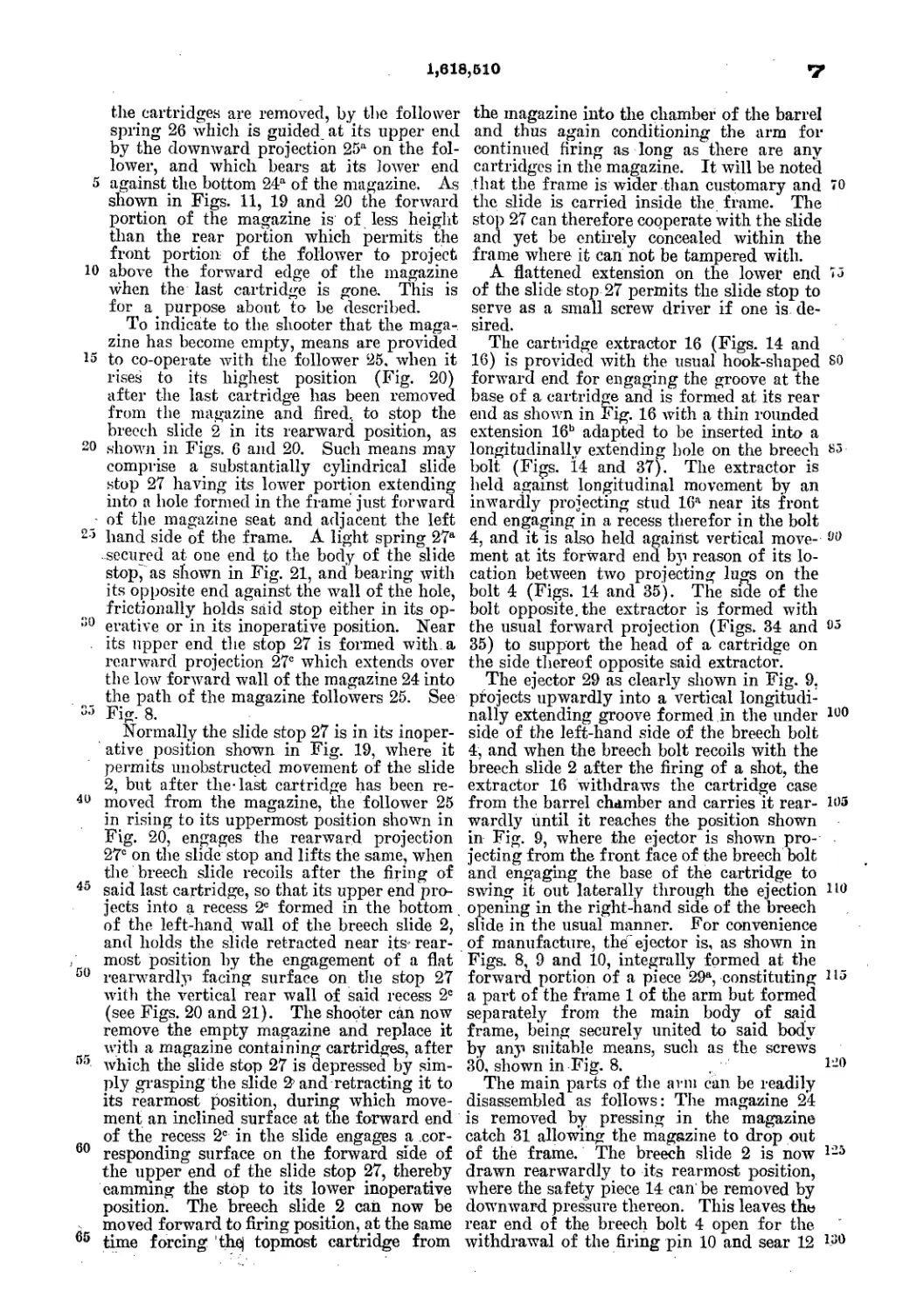
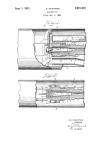
In the drawings, Figure 1 is a longitudinal
central section. Fig. 2 is a top view with the
25 bolt removed; Fig. 3, a bottom view of the
bolt; Fig. 4, a side view of the same; Fig. 5,
a section of the bolt on line x x; Fig. 6, a side
and top view of the carrier; Fig. 7, a section
of the bolt-head; Fig. 8, a modification of the
30 carrier.
In these drawings, the stock of the gun is
represented by A, the barrel by B, and the
magazine by G. The latter is inclosed within
that portion of the stock which partially sur-
35 rounds the barrel, and is a metallic tube of any
desired length, provided with the usual spring
aud follower for pressing the cartridge con-
stantly backward in thedirectionofthereceiver.
D is the receiver, which is slotted longitudi-
40 nallyfrom top to bottom a sufficient distance to
permit the necessary movement of the carrier
in conveying a cartridge from the magazine to
the chamber.
The carrier E is pivoted on a transverse pin,
45 1, secured in the walls of the frame, and ex-
tends forward, as usual, to the mouth of the
magazine. It is provided with a rearward pro-
jection, 2, which extends np through a slot in
the bolt-groove. Forged solid with or secured
to this carrier at a point just forward of thf 50
bolt-groove is a block, 3, which is more par-
ticularly illustrated in Figs. 2 and 3.
In the top of the block is a rounded inclined
groove, c, extending down in the direction of
the magazine when the carrier is in position. 55
The walls of the slotted receiver from the
block just described to the chamber and mag-
azine are formed with intersecting grooves a
b, so that thebody and head of a cartridge may
be inserted at a point justforward of the block; 60
but beyond this the diameter of the slot is re-
duced by means of the tongue or portion of
wall between the grooves, and will not admit
the head. This construction aud that of the
grooved block 3 are for the purpose of facilitat- 65
ing the charging the magazine directly from
the rear, dispensing with the necessity for a
spring-carrier, and constituting a marked im-
provement upon the method of charging from
the side or bottom, as usually practiced. 70
In charging the magazine the bullet of the
first cartridge is placed in the groove c in the
block 3 and pushed forward, The carrier is
forced down to its lowest position, and the
cartridge, guided by the walls of the receiver, 75
is introduced onto the carrier, the follower
acting as soon as the head of the cartridge is
pressed down to the carrier to force the car-
tridge back against the block 3, where it is se-
curely held. The next cartridge is pressed 80
down the incline against the first, and forces
it forward into the magazine. Under ordinary
circumstances, with a receiver having vertical
sides, this would not be practicable, since the
following cartridge would pry up the leading 85
one, and by passing under it throw it ont of
the receiver. It will be seen, however, by ref-
erence to Fig. 1, that the groove a extends
forward from the block 3 to the magazine,
against the upper edge of which the head of 90
the leading cartridge will come in contact as
it is pushed forward and prevent any upward
movement.
Practically an angular groove or way of the
diameter of a cartridge-head is formed in*the 95
wall of the receiver, extending from the maga-
zine back to the block 3, forming the path of
discharge. Successive cartridges are forced
2
261,66?
into the magazine in this manner, the last car-
tridge remaining on the carrier held firmly be-
tween the preceding cartridge and the block 3.
By the pecnliar form of the receiver we are
5 enabled to dispense with clamps, fingers, or
other devices for holding the cartridge upon
the carrier. s
Immediately above the block 3 are projec-
tions 5 5 on the walls of the receiver, against
io which the head of the cartridge strikes when
the forward end is thrown np for insertion into
the chamber, and by which the head is .held
in position to receive the impact of the bolt G.
The bolt-groove F is cylindrical in shape and
15 contains two slots, 6 and 7, as shown in Big.
2, the forward, 6, to permit the vertical arm of
the carrier to project into the path of the bolt,
and the rear slot, 7, to permit the dog or trig-
ger to project through in order to engage with
20 the hammer or cocking-piece.
The bolt is represented as a whole by G. Tt
is constructed in three parts—thecocking-piece
Ы, having the central stem and firing-pin at-
tached, the locking-sleeve I, adapted to rotate
25 on the central sleeve, and having the usual
lever-handle, and the bolt-head J, which fits
over the forward end of the firing-pin, and is
bored out centrally to permit the pin to work.
The usual stiffcoil-spring surrounds the central
30 pin for forcing the firing-pin forward. The
stem or firing-pin is flattened on one side.
The extractor 9 is secured in a groove in the
side of the bolt-head, and projects forward of
said head, and is provided with the usual hook
35 for grasping the flange of the cartridge.
It may happen sometimes that by the burst-
ing of the cap the firing-pin is forced violently
back against the spring, by which there is dan-
ger of breaking the latter. We avoid this
40 danger in either of two ways—in one by mak-
ing an offset, 10, on the firing-pin, which, should
the latter be forced back, would strike the end
of the extractor 9, which projects through the
shell of the bolt-head, forming a stop; bnt we
45 prefer to nse the device illustrated separately
in Fig. 7. Here the rear end of the extractor
does not project into the interior of the bolt-
head, but the bore of such head is cylindrical
and unobstructed throughout. The forward
50 end of the firing-pin is flattened, as shown, and
it is provided with an offset in which the pin
slides. A screw-thread is tapped through the
shell of the bolt-head, and a screw-stop pro-
vided against which the offset bears if the pin
55 should be forced back with nndue violence,
th ns preventing too great compression of the
spring. We also drill a small vent-hole, 11,
in the shell of the bolt-head, to permit the
gases generated by the bursting of the cap to
60-escape.
In arms of this class, so far as we are aware,
the carrier has been depressed by the end pro-
jecting into the bolt-groove being struck by the
bolt as it moves forward.
65 As an improved construction, we form the
locking-sleeve with a longitudinal slot, as
shown in Fig. 5, by which the bolt is allowed
to slide freely over the projecting end of the
carrier on the forward movement.
A cam, 12, is formed on the locking sleeve, 70
(shown in Fig. 5,) which is brought to bear on
the projection 2 of the carrier when the lock-
ing-sleeve is turned down. The sleeve turns
against the incline 13 on the frame, and the
combined rotary and forward motion of the 75
sleeve depresses the forward end of the car-
rier in position to receive a cartridge from the
magazine.
The cocking-piece is provided with a deep
half-cock notch, 14, which catches the dog when 80
pulled back slightly, and prevents any for-
ward movement of the bolt.
When the piece is at half-cock the sleeve of
the bolt is also locked in a closed position by
the projection 15 on the trigger locking with 85
- the groove or recess 16 on the locking-sleeve,
until the bolt is drawn back to full-cock.
Therefore the bolt can have no forward and
the sleeve no rotary movement.
Instead of the ordinary trigger-spring bolted 90
to the frame:behind the trigger and pressing
the latter constantly forward, we have devised
an improved constrnction, (shown at M, Fig.
1.) The spring here serves the double purpose
of actuating the trigger and steadying the 95
rear end of the carrier, whether elevated or
depressed. It is centrally bolted to the frame
npon one side of the central slot, and its rear
free end bears constantly upon the horizontal1
arm of the trigger. The forward free end 100
bears npon the periphery of the rounded end
of the carrier, which is provided with depres-
sions 30’40. The pressure of the spring in
either of the depressions, according to whether
the carrier is elevated or depressed, is suffi- 105
cient to hold such carrier steady and to pre-
vent any possibility of the movement of the
carrier except at the proper time. It is not
sufficient, however, to impede free movement
of the carrier, since the spring yields readily no
to the back-pressure of the bolt on the pro-
jecting rear end of the carrier.
In Fig. 8 is illustrated a modified form of
carrier. Here the block 3, formerly described
as secured to the carrier, is attached to or 115
forms an integral partof the frame, the groove
being formed in the same way, and the head
of the cartridge bearing against it in the same
manner.
In the operation of the device the maga- 120
zine is loaded as before described, the last car-
tridge remaining on the carrier. The bolt is
drawn back, the projection on the front strik-
ing the projection 2, tilting the carrier on the
pivot-pin, and raising the forward end. The 125
front eud of the cartridge strikes the frame
above the chamber, while the head tips back
under the projections 5 5 above the block 3,
and the entire cartridge is thus held in po-
sition to receive the impact of the bolt. The 130
bolt is pushed forward, forcing the cartridge
on the carrier into the chamber, while the ex-
‘.>61,66?
tracting-hook grasps ihe flange. The locking-
sleeve is turned down, the earns acting on the
projection 2, depressing the carrier, and an-
other cartridge is forced onto the carrier
5 against the shoulder 3. The rotary movement
of the locking-sleeve_.cocks the piece, which is
now ready to be fired. When fired the lock-
ing-sleeve is turned up and the bolt withdrawn,
the extractor carrying the cartridge, which is
io thrown out of the chamber by the extractor
pressing the head against the side of the re-
ceiver. At the same time another cartridge
has been elevated, and the gun is ready for re-
loading.
15 This arm possesses the merit of simplicity
both in construction and action, of accessibility
for cleaning and repairing purposes, and is re-
liable, efficient, and easily operated.
Having thus described our invention, what
20 we claim is—
1. In a magazine-gun, the combination, with
the magazine closed except at the rear end
thereof, aud having the spring-follower, of the
receiver D, the carrier pivoted in the bottom
25 of such receiver, and the grooved block 3,
against which the head of each cartridge is
forced by the magazine-spring in position to
be acted on hy the succeeding cartridge.
2. The combination, in a magazine-gun, of
the receiver D, the magazine situated below 30
the barrel, and having the spring, the pivoted
carrier, and the block 3, mounted thereon and
having an inclined groove, whereby each car-
tridge is pressed back against such block and
may be forced into the magazine by means of 35
the succeeding cartridge.
3. : The combination of the pivoted carrier,
the block 3, having inclined groove, and the
receiver having grooves a in its walls above
the carrier when at its lowest position, where- 40
by an angular way is formed for the insertion
of cartridges into the magazine from above,
substantially as described.
4. In a magazine-gun, the combination of
the pivoted carrier having the projection 2, the 45
locking-sleeve having longitudinal groove,the
cam 12, and the incline 13 on the frame.
In testimony whereof we have signed our
names to this specification in the presence of
two subscribing witnesses.
JOHN M.- BROWNING.
MATTHEW S. BROWNING.
Witnesses:
C. F.-Middleton,
O. R. Child.
(No Model.)
2 Sheets—Sheet 1.
J. M. & M. S. BROWNING-.
MAGAZINE GUN.
2 Sheets—Sheet 2.
(No Model.)
J. M. & M. s. BROWNING.
MAGAZINE GUN.
No. 282,839.
Patented Aug. 7, 1883.
United States Patent Office»
JOHN M. BROWNING AND MATTHEW S. BROWNING-, OF OGDEN, UTAH
TERRITORY.
^AGAZiNE-GUN.
SPECIFICATION forming part of Иййега Patent No. -282,839, dated August 7, 1883.
Application nlei! September 13, 1882. (No model. ';
To all whom it may concern,:
Be it. known thatwe, Jno. M. Browning and
M. S. Browning, of Ogden, in the county of
Weber and Territory of Utah, have invented
5 a new and useful Improvement in Magazine-
Guns; and we do hereby that the following is a
full, clear, and exact description of the same.
Our invention relates to improvements in
magazine fire-arms; and the object of the in-
io vention is to render the arm more certain in
operation and effective in use by decreasing
he number of working parts, and thereby
greatly simplifying the action of the gun.
The invention pertains to that class of re-
15 peating-rifi.es in which the magazine is located
beneath the barrel, from which the cartridges
are expelled by a spring-follower into the re-
ceiver and upon a carrier, by which they are
elevated to a position opposite the chamber
20 of the gnu, into which they are driven by a
breech-block and lever operating from the
under side of the gun, and which serves also as
a trigger-guard.
The invention consists, first, in the peculiar
25 manner of connecting the breech-block to the
receiver, by which it is given a combined slid-
ing and pivotal motion: further, in the com-
bination of such a breech-block and the pe-
culiar extractor; further, in the manner of
30 attaching the carrier to the receiver; and, gen-
erally, in the peculiar construction ami ar-
rangement of the various parts and in the va-
rious operative combinations of such parts,
all fully hereinafter explained.
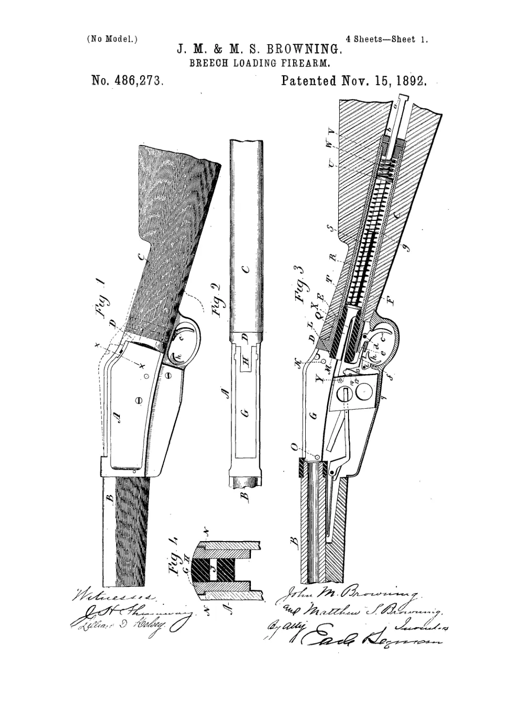
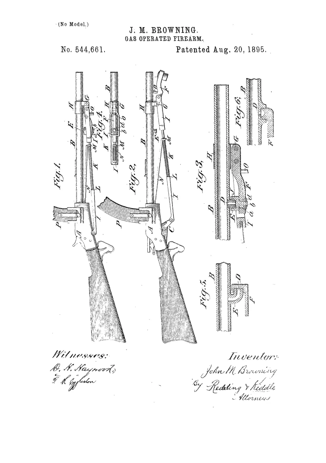
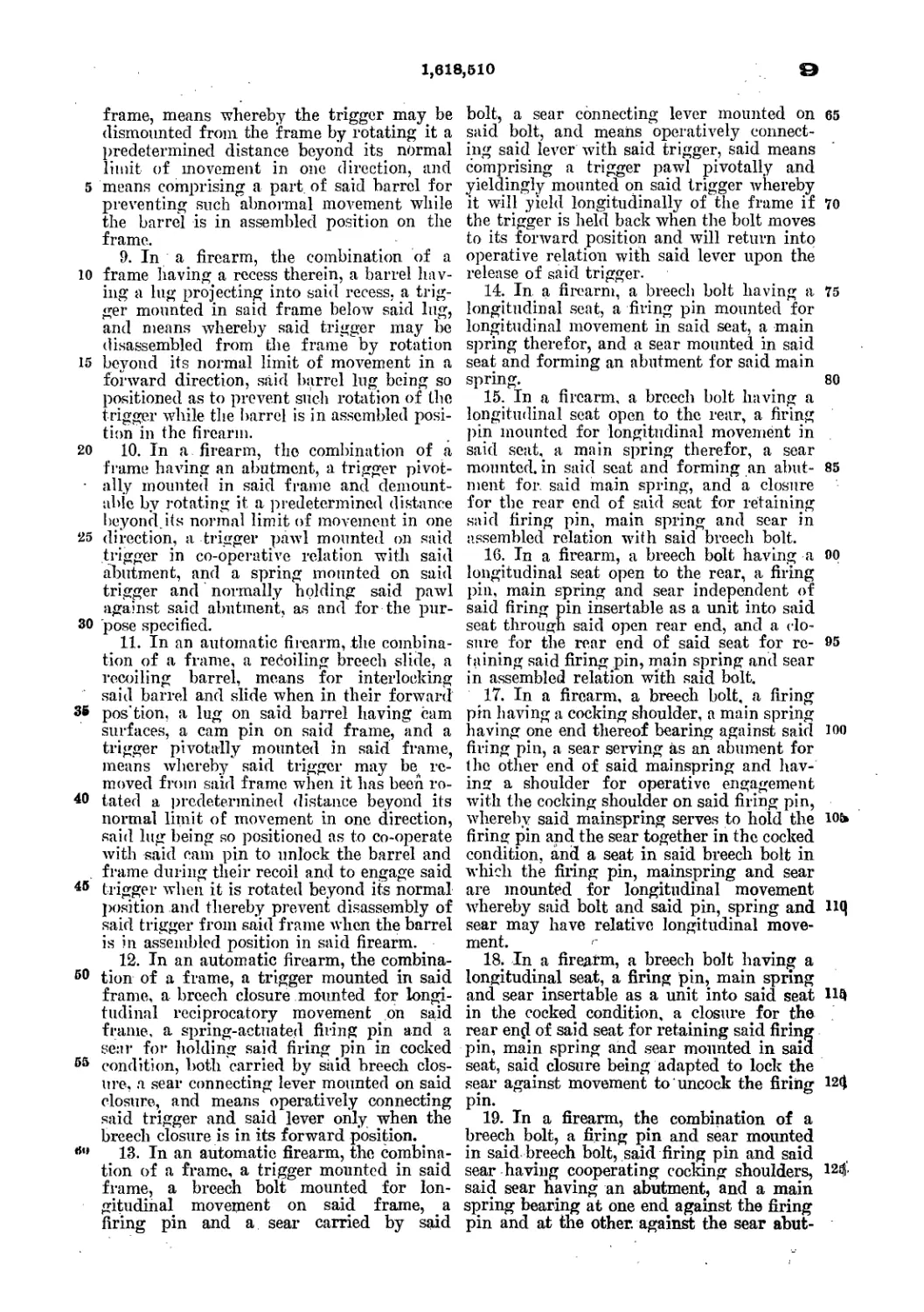
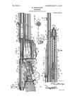
35 In the drawings, Figure 1 represents in part
a central longitudinal section, with some of
the parts in side elevation. Fig. 2 represents
the carrier in plan. Fig. 3 represents, in sec-
tion and side elevation, the opposite side from
40 that shown in Fig. 1. Fig. 4 is a similar view,
with the breech-block in full lines; Figs. 5,
(>, and 7, separate views of the breech-block.
Д represents the stock.’ and В the barrel,
both of ordinary form and construction.
45 C is a magazine-tube, rigidly secured below
the barrel of the gun, the rear part being in-
closed by the stock, as usual in arms of this
class. The magazine is provided with the or-
dinary spring-follower, and preferably extends
to the muzzle of the gun, thus being adapted 50
to hold a large number of cartridges. 1
D represents the receiver, which is “slotted
vertically from top to bottom, and communi-
cates with the magazine at its lower forward
encl, and above with the chamber of the gun. 55
The receiver is provided on one side with a
slot, 1, extending for almost its entire length,
which slot is on a line with the chamber of
the gun. A similar slot. 2, is formed in the
opposite side of the receiver. ' 60
The magazine is loaded by means of a spring-
trap, 3, in the side wall thereof, the cartridges
being forced through snch trap and into the
magazine, each cartridge being impelled for-
ward by the succeeding cartridge until the 65
magazine is full.
E represents the carrier, which is shown
separately in Fig. 2. This carrier is of angu-
lar shape, and is provided at its forward end
with a concave rest or support, the forward 70.
end of which is hr cluse proximity when the
carrier is depressed to the month of the maga-
zine, and on which the cartridge rests when
expelled therefrom. The rear arm of the car-
rier -1 fits snugly in a slot, 5, in the side wall 75
of the receiver, and such arm is provided
with a round stud. (>, which enters a perfora-
tion in the side will, by which the carrier is
held in operative position. The upper end
of the slot 5, in which, the carrier is placed, 80
communicates with the slot 2, before mem
tioned, and the rear arm of the carrier ex-
tends up to a point opposite the termination
of such slot 2, the slot 5 being extended back
a short distance, in order to give play to the 85
carrier when moved, as hereinafter described.
E represents as a whole the combined breech- •
block and lever, which is shown separately in
Fig. 5. This lever is of a peculiar shape, as
sho wn, the upper end, which is nearly st raight, 90
being adapted to close the receiver when the
arm is ready to be fired. The lever is bent
as indicated at S, and extends downward
through the receiver and behind the rear end
of the carrier, terminating in an ordinary trig- 95
ger-guard and handle, 9, and having shoulder’s •
10 10, which bear against the plane face 11 on
the receiver, a spring friction-stud, 12, having
2
aroundcd.en!?,bein£ •>«
.feteecfi-block Ifta »!<•—
against the inner w i1!
breech-block is gnit
pin, 13, which is in,' n'„l ।
in the side of the гем г
a corresponding hoi" ,
block. The end of
through the hole an 1
the slot 2,while its otl, ।
the block, enters ara,
The extractor is
consists of a plate, 15, c. <
it will fit snugly in the
having at its forward e
engage with the flange > 1 x <
chamber. A springTll;
tractor, and bears agair i«
and tends to throw 11
:ard oi' ths
aii >
'lock, slides in
ic
u I 1
11 f _ I. J,
ho t 'hat
t < i\er,
>. ’ :o
i ic
’ i r< t! i i
111 ll< W0V
1 i ill fl c
gage with-the cartrnl,r i <tv i л
the extractor and bie< i ’ >< i ’ ,c ню <
together by the pin
moved the extractsi
locating movement in
ver has both a sliding
olal movement on fl <
of the block is a not' n
'notch the block is b>
thepurposehereinaf1 г <
block is bored out
the firing-pin 20. h >
.strong 'spring, and is
tndinally in such bore
The hammer I is pi voted upon a pin, 19,
and operates ju connection with the Irigger ,T,
pivoted upon a pin, 21., both pro vided with
the usual springs. In addition to the usual
half-cock notch, I employ a safety-catch, which
holds the hammer locked a slight distance
from the firing-pin. Upon the hammer is a
projection, 22, which, when such hammer is
at the safety-catch just described, engages with
a notch, 23, in the rear end of the breech-block
and locks such block rigidly io a closed, posi-
tion.
The lower opening of die receiver is closed
by means of a bottom plate, K, provided at its
forward end with, a projection, which enters a
notch in the adjacent wall of the receiver, and
at its rear end with, projecting lugs, through
which is passed a pin, 27. The awn of the le-
ver works in contact with the rear end of th is
bottom plate, it being curved for thabprtrpos.e.
as shown. In the operation of this arm the
breech-block is thrust down, the pin 13 strik-
ing the rear arm. of the cardri ’nd throwing
the forward end up. The ne is then
loaded through the spring n »t , nd at the
same time a. cartridge may 1 < Л in. the
chamber of the gun from above 1 j < breech-
block is now closed and the piei ’ vmled, and
at the same time the carrier is forced down to
hell, and as the lever is pressed down
’ 1 i jiactor moves directly back in the
carrying the shell with it. At the
e another cartridge has been gradu- 70
J 11 к ced by the magazine-spring upon the
( < I nr After, the cartridge is drawn from
iber, the flange is released by the ex-
ши the notch 17 in the forward end
o&k seizes the flange and draws the 75
! ebac-k. Atthispointtbepin 13strikes
c i 1 arm of the carrier, throwing its for-
i end up, not only placing the cartridge
i last taken from the magazine in position to be
i forced info the chamber, but also throwing the 80
। exploded cartridge completely out of the re-
; The loaded cartridge is prevented
; from following it by its bullet Striking against
I the upper wall of the receiver, in the rear of
1 11 umber, while its head conies in contact 85
1 л 1’><5 forward end of the breech-block.
li । ' tier is held in its elevated position
’ <<' *h< succeeding cartridge being forced
_ 1 - t if the magazine is empty, by the
’ ’' • ver. The breech-block is then 90
1 i 1 1 fresh cartridge driven into the
hen t he gun is ready to be fired,
seen that the gun can be used with
Ly as a single-loader, since when
>.4 in its elevated position the car- 95
' и id tie. simply dropped upon thecar-
above and then forced into the cham-
j.t r losing the breech-block.
1 It will be noticed that the working parts of
j this gun, setting aside the magazine, hammer, 100
j and trigger, are only three in number—hame-
1 ly, the breech-blockj carrier, and extractor.
All springs are dispensed, with.
Having thus described our invention, what
we claim as new, and desire to secure by Let- 105
tors Patent, is—
* r' i magazine-gun, the combination of a
’'w. i-i r r chamber communicating both with
Ji ; i, •, t/.inc and the barrel, cartridge carry -
ii’", . 1 'xtracting devices, and a solid breech- no
block 0 nd lover, formed in one piece, and hav-
ing a combined sliding and piyptal movement
in the receiver, such breech-block having a
plane smooth upper surface, adapted, whenthe
breech is closed, to be flush with the upper 115
edge of the walls of the receiver and form the
i top and closing plate thereof.
I 2. The receiver I), hal ing the slots 1, 2, and
j -5, in combination with thb breech-block, the
I extract or, the pin 13, connecting such breech- 120.
i block and extractor and. projecting into the •
• said slot 2, and the vibrating carrier E, mount-
i cd in the said slot 5, and having its rear end
projecting up opposite the said slot 2, in po-
sition to be struck by the pin 7 when the breech- 125
block is drawn down.
3. The receiver having the communicating
slots .2 5, in combination with the carrier hav-
) :ing the turned rear edge adapted to be se-
cured within such slot 5, to operate in connee- 130
tion. with the described breech-block.
I 4. In combination with the slotted receiver,
its lowest position in line with the magazine.
After firing, the gun is placed either at half or
full cock and the. lever forced down. The
extractor has grasped the flange <5f the ex-
the breech-block, the yibraang carrier, and
the extractor, arranged substantialiy as de-
scribed. the yin 13. passing through the rtaid
breech-block and pivoting it про;! the ex-
5 tractor, and projecting into the she 2, to oper-
ate in connection v.’illi the Vibnifiug wrier.
In testimony •.’.•hereof we have signed our !
muiics to this spediication in the presence o<
4,’ЦЧ/ ;StlJ iScHb! 11‘Д \\ ] t ncsscs.
XOiiN hl. BROWNING.
3IATTHEW S. BKOWKfNG.
Witnesses:
Ik W. Г'-ГГЛИАМ',
ЛТЛ’ЯА. kgfXTNGER.
3 Sheets—Sheet 1.
(No Model.)
J. M. & M. S. BROWNING.
MAGAZINE FIRE ARM.
No. 306,577.
Patented Oct. 14, 1884.
(No Model.)
3 Sheets—Sheet 2.
J. M. & M. S. BROWNING.
MAGAZINE FIRE ARM.
No. 306,577.
Patented Oct. 14, 1884.
3 Sheets—Sheet 3.
(No Model.)
J. M. & M. S. BROWNING.
MAGAZINE FIRE ARM.
No. 306,577. Patented Oct. 14, 1884.
United States Patent Office.
JOHN M. BROW! rNG AND MATTHEW S. BROWNING, OF OGDEN, UTAH TER-
RITORY, ASSIGNORS TO THE WINCHESTER REPEATING ARMS COMPANY,
OF NEW HAVEN, CONNECTICUT.
MAGAZINE FIRE-ARM.
SPECIFICATION forming part of Letters Patent No. 306,577, dated October 14,1884.
‘ Application filed May 26,1884. (No model.1
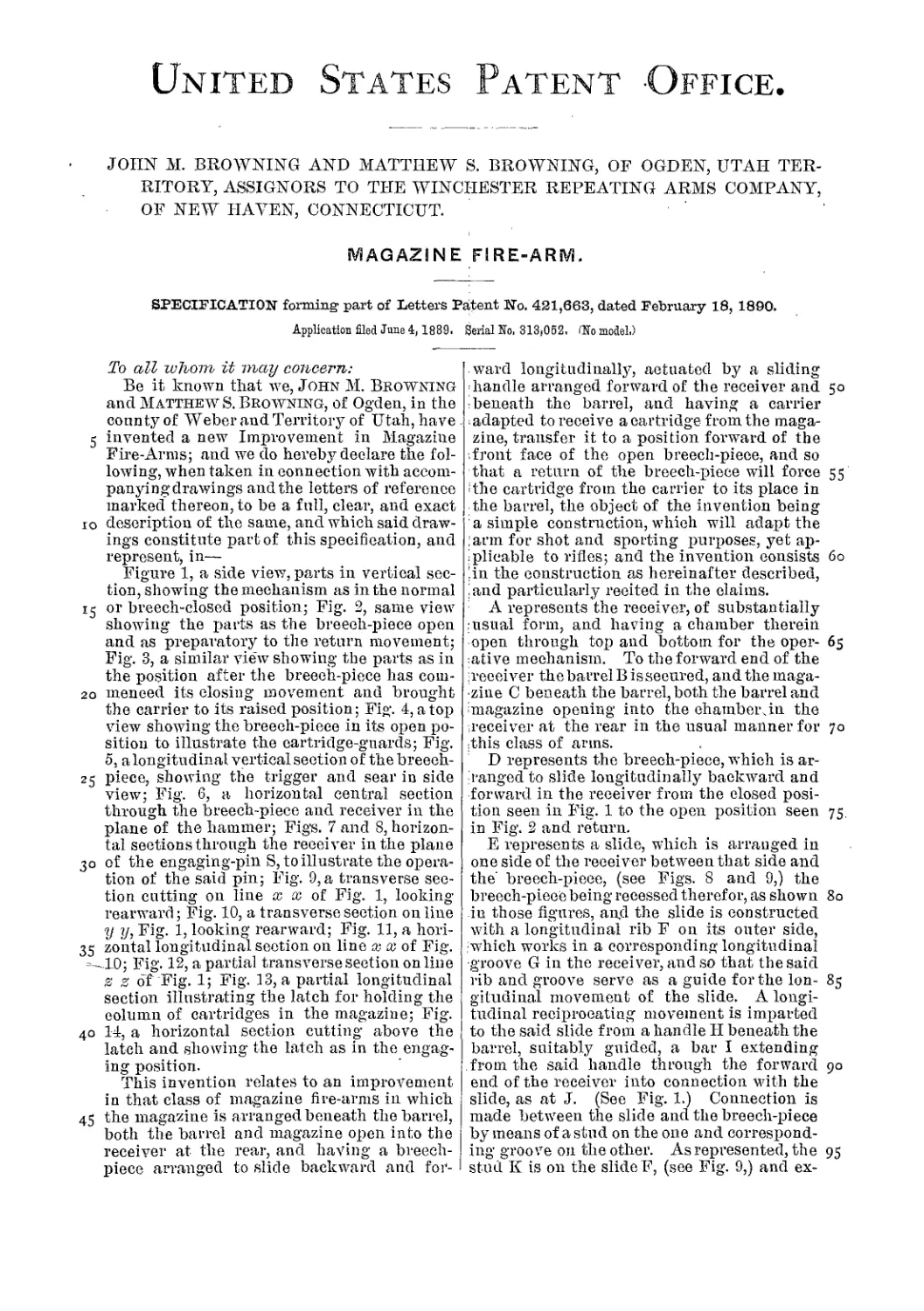
To all whom it may concern:
Be it known that we, John M. Browning
and Matthew S. Browning, of Ogden, in
the county of Weber, Utah Territory, have in-
5 vented a new Improvement in Magazine Fire-
Arms; and we do hereby deelare the following,
when taken in connection with accompanying
drawings and the letters of reference marked
thereon, to be a full, clear, and exact deserip-
io tion of the same, and which said drawings con-
stitute part of this specification, and repre-
sent, in—
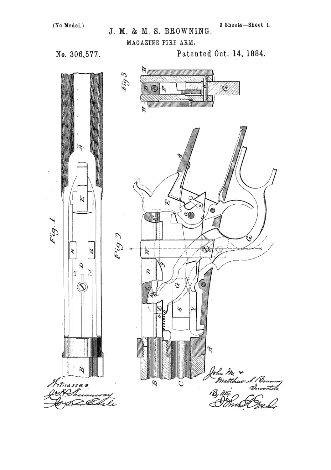
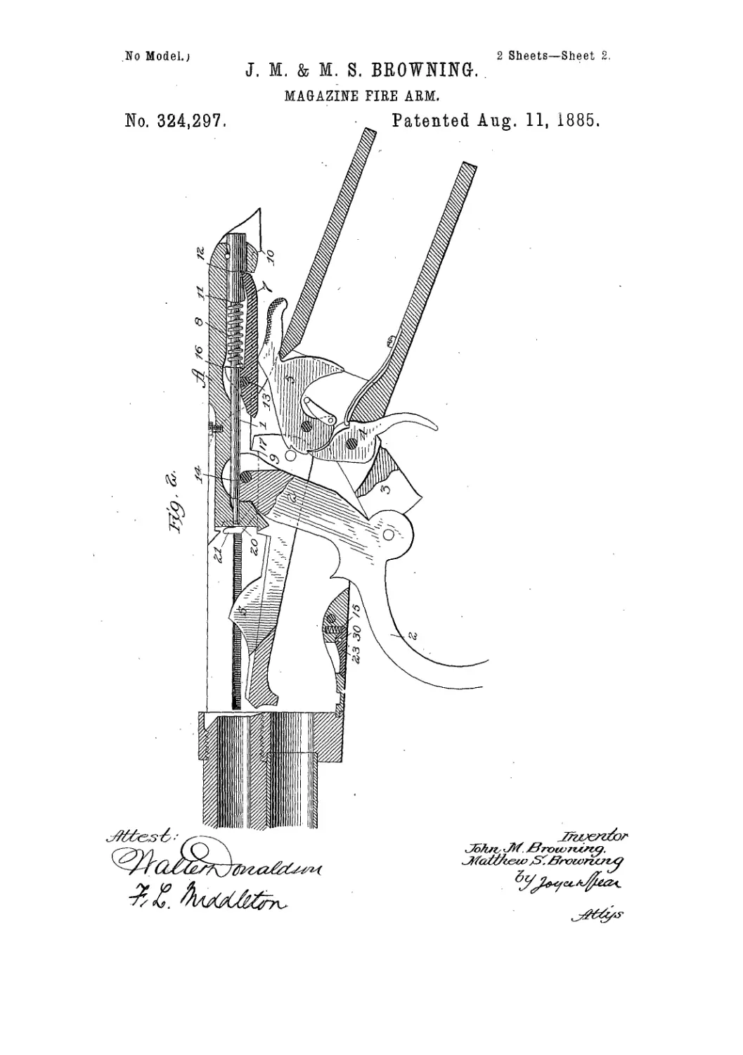
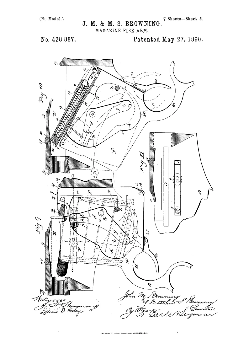
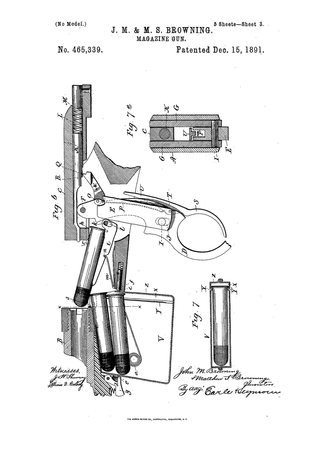
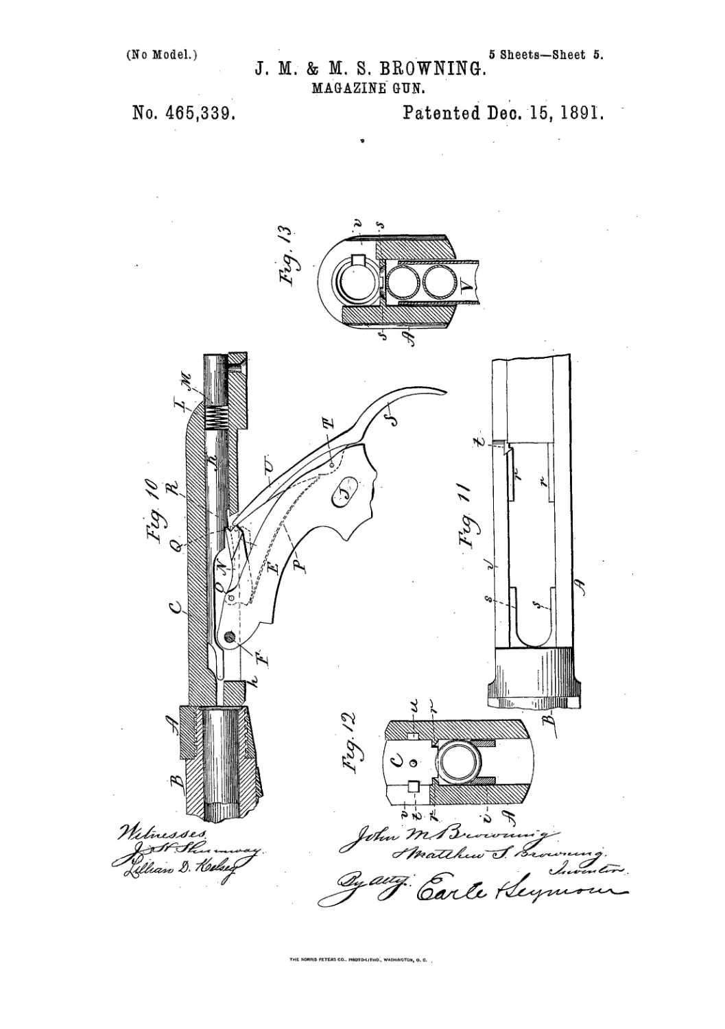
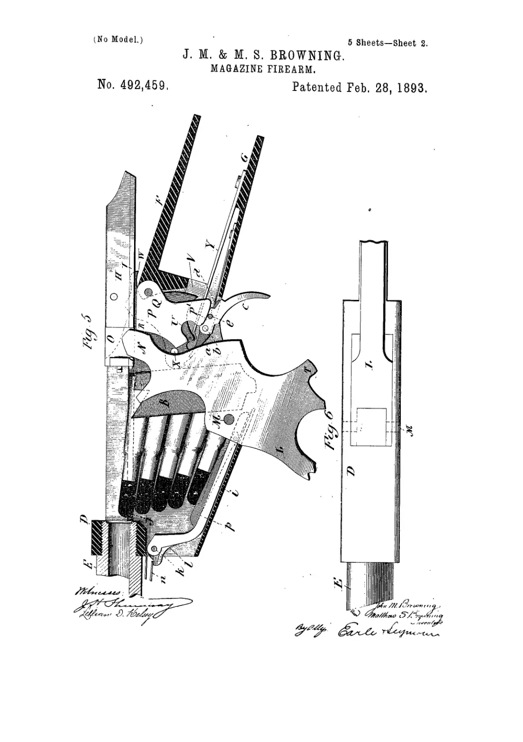
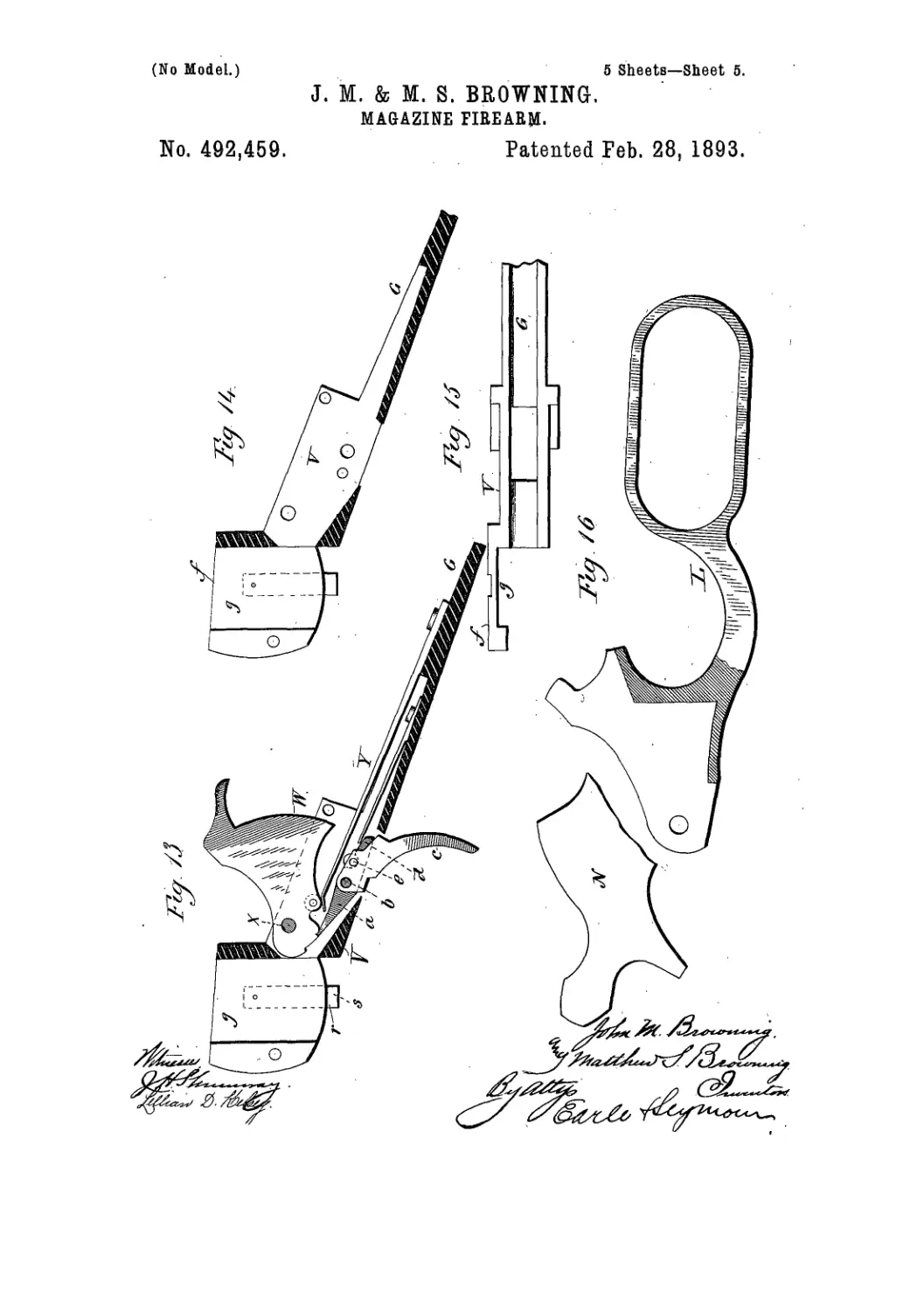
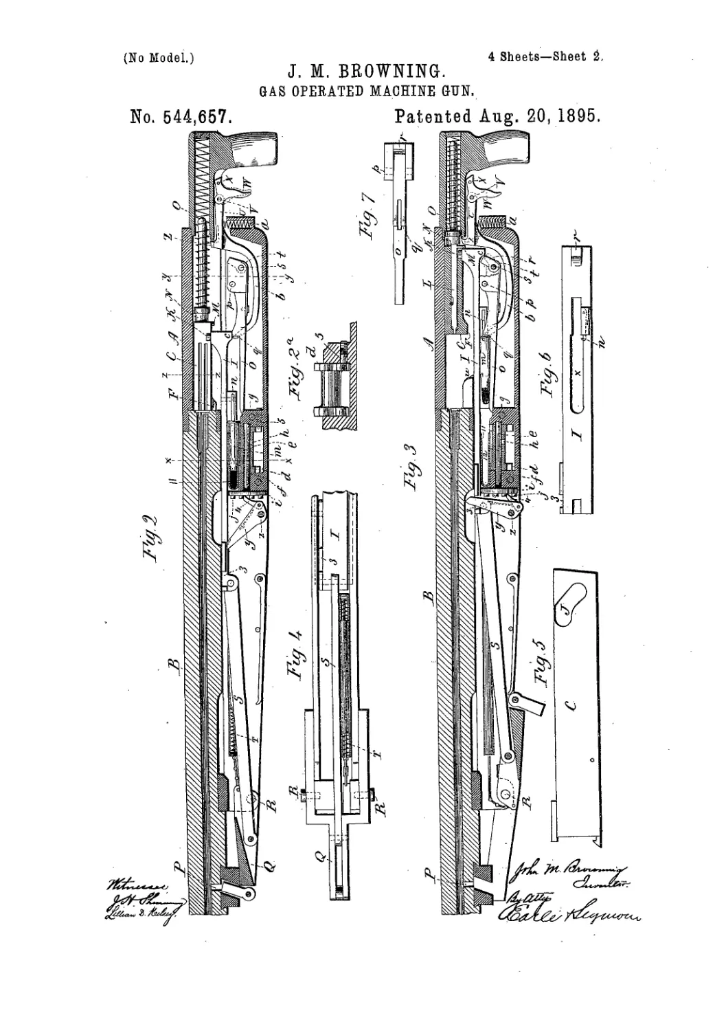
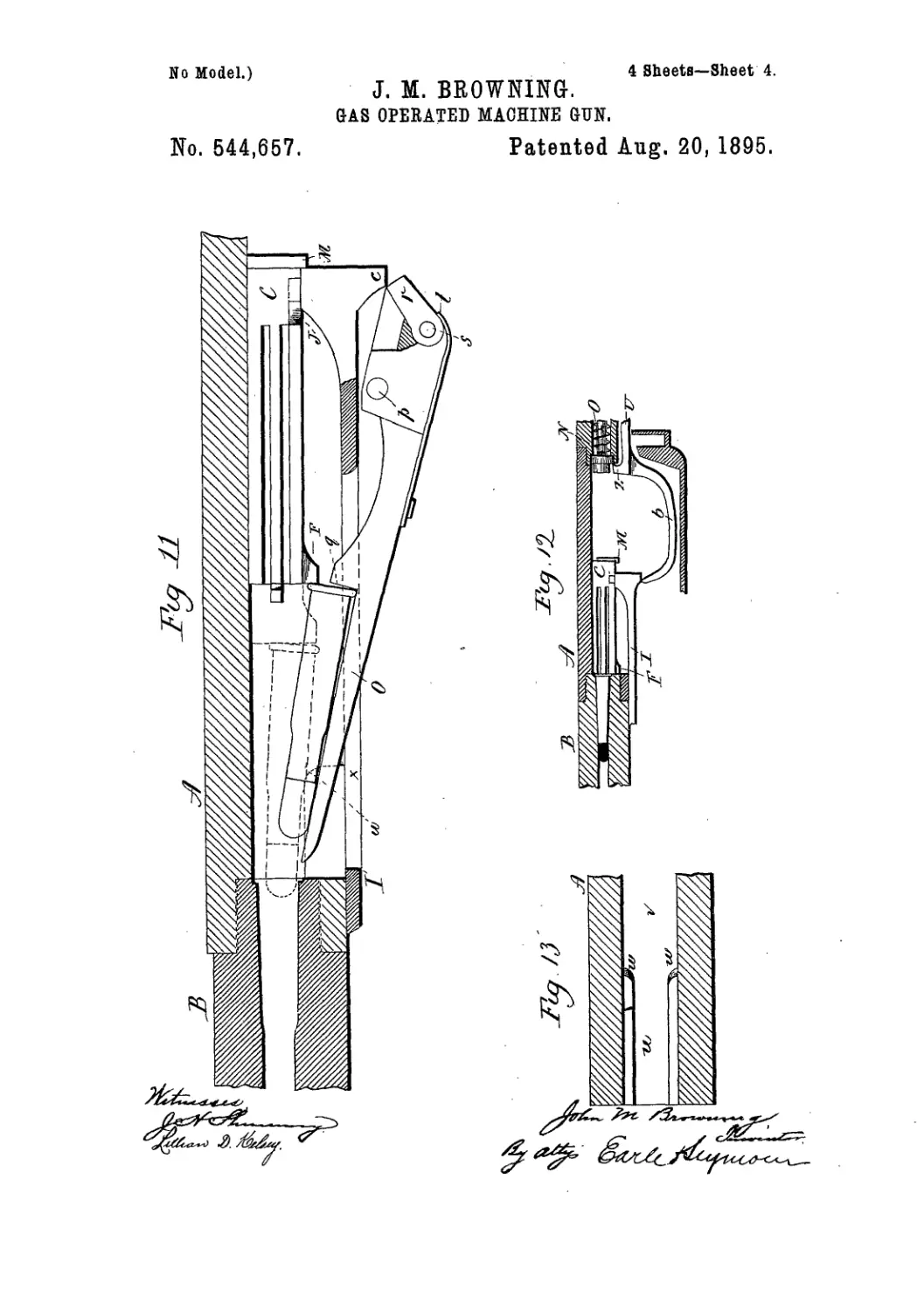
Figure 1, a top view of that portion of the
arm which embodies our invention; Fig. 2, a
15 longitudinal sectional side view of the same,
showing the parts in their closed or normal
position; Fig. 3, a vertical section on line x x
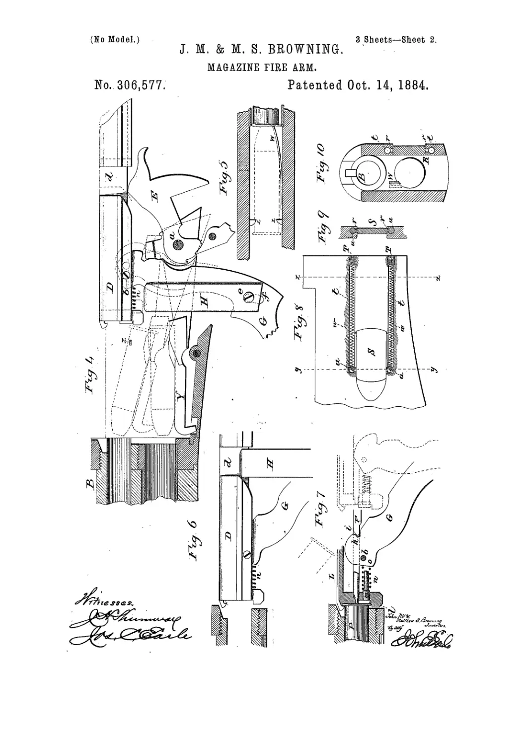
of Fig. 2; Fig. 4, a sectional side view showing
the parts as in position of the open breech;
2Э Fig. 5, a horizontal section through the receiv-
er, showing the spring W with the inwardly-
projecting lugs ZZ; Fig. 6, a sectional side view
illustratingthe closing movement of the breech-
piece; Fig. 7, a longitudinal section through the
23 breech-piece, showing the lever, itsactioh upon
the firing-pin and the ejector; Fig. 8,aseetional
side view of the receiver, showingthe arrange-
ment of the slide in closing the magazine-
opening; Fig. 9, a vertical central section on
30 Вое у у; Fig. 10, a vertical central section on
line z z, looking toward the barrel and maga-
zine, and also showing the relation of the
spring W to the magazine; Figs. 11,12, and
13, modifications.
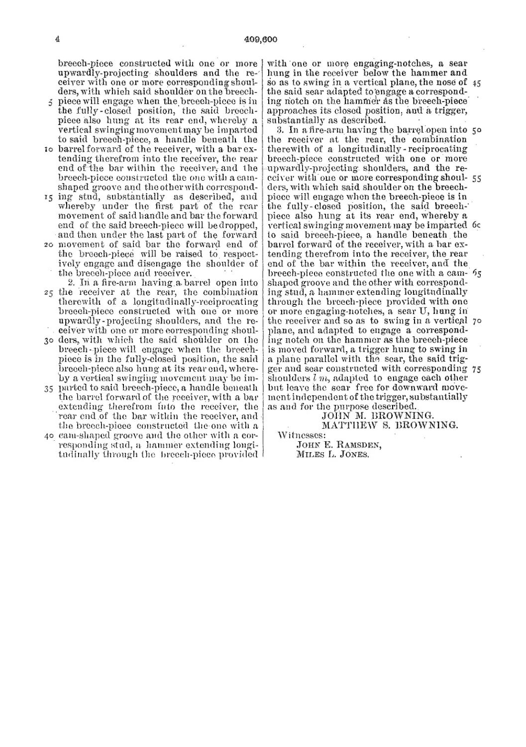
35 ’ This invention relates to an improvement in
' that class of breech-loading fire-arms in which
the breech-piece is arranged to be moved back
and forth in an axial line with the barrel and
operated by a lever in connection therewith,
40 which extends below the receiver to form the
trigger-gnard,.adapted specially to magazine
fire-arms, but applicable to single breech-load-
ers, the object of the invention being princi-
pally to make a dead-lock for the breech-piece
45 when in its closed position; and the invention
consists in the construction, as hereinafter de-
scribed, and more particularly recited in the
claims.
A is the frame of receiver, of usual construc-
tion; B, the barrel; 0, the magazine in their 50
usual relation to each other and to the re-
ceiver; D, the breech-piece, arranged to be
moved longitudinally from the rear end of the
barrel to open and toward it to close the
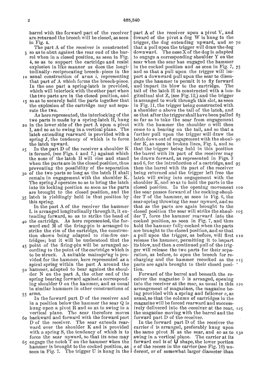
breech; E, the hammer, hung upon a pivot, a,' 55
at^the, rear of the breech-piece, and so as to
strike the firing-pin F, which is arranged lon-
gitudinally through the breech-piece in sub-
stantially the usual manner; G, the trigger-
gnard lever which forms the trigger-guard, 60
and also serves as a means for operating the
mechanism of the arm. It is hung to the breech-
piece upon a pivot, b. near the forward end.
From that point the lever extends downward
and rearward through an opening in the bottom 65
of the receiver. H H are two bolts arranged
in vertical guides in the receiver, near its rear
end, and so as to be moved up and down in the
said guides. Near the rear end of the breech-
piece D, and upon opposite sides, are recesses 70
d, which, when the breech-piece is in its closed
position, correspond, respectively, to the po-
sition of the vertical bolts H II, and as seen
in Fig. 1, so that while the bolts are guided
in vertical movement by the receiver they in- 75
terlock with the breech - piece when in its
closed position. These bolts extend down-
ward, and to their lower end the lever G is
hung by a pivot, e, as seen in Fig. 3. This
pivot extends through a slot,/, in the lever 80
G, the slot, as seen in Fig. 2, extending from
the pivot rearward and downward when the
parts are in the closed position. To open
the breech-piece it is therefore necessary to
first withdraw the bolts H. To do this the le- 85
ver G is turned downward, swinging upon its
pivot & in the breech-piece, as indicated in
broken lines, Fig. 2. In this movement the
bolts H are drawn downward, the slot / in the
lever working over the pivot e until the rear 90
end of that slot is reached, as also seen in
broken lines, Fig. 2. At this time the upper
ends of the bolts have been drawn downward
from their supporting position in the breech-
piece, as seen in Fig. 2, but have not as yet 95
passed entirely from or below the breech-piece.
The forward side of the recesses in the breech-
piece from the point where the end of thebolt
306,577
now stands are inclined fot'wdrd, aS Seen at
g, Fig. 2. Continuing the downward move-
ment of the lever Gfrom the position seen in
broken lines, Fig. 2, the bolts will continue
5 their downward vertical movement; but at the
same time the breech-piece, because of the in-
clines g, may pass over the ends of the bolts
H to the extreme rear position, as seen in Fig.
4, which is the extreme open position of the
io breeeh-piece. In this open position it will be
observed that the slot f in the lever stands
nearly in a vertical position.
To return or close the breech-piece, the lever
G is returned, swingiug upon the pivot e. The
15 breech-piece will move forward withoutmove-
ment of the bolts until it arrives at the posi-
tion seen in Fig. 6, when the rear end of the
slot f comes against the pivot e. At this time
the breech-piece is near, but has not quite
20 reached, its closed position. From this point
the bolts must begin their ascent, and in such
ascent they ride upon the incline g from the
position seen in Fig. 6 until the breech-piece
is completely closed. Then the slot/ actslike
25 a cam npon the pivot e to raise the bolts into
their extreme locked position, as seen in Fig.
2, at which time the lever G has arrived at its
place of rest.
To withdraw the firing-pin and hold it so as
30 to prevent possible accident, the upper end of
the lever G in rear of its pivot is constructed
with a cam, Л, which stands in a recess iri the
firing-pin and overhangs a corresponding in-
clined shoulder on the firing-pin, as seen in
35 Fig. 7, but which, when the breech-piece is
in its closed and locked position, permits the
firing-pin to be moved into its extreme for-
ward or firing position under the blow of the
' hammer; but as the lever G is turned in its
40 first movement to draw down the bolts H, aud
before the breech-piece commences its rear
movement, the cam h acts upon the' shoulder
i on the firing-pin and throws it rearward,
as indicated in broken lines, Fig. 2. Because
45 of arranging the cam on the lever in rear of
its pivot, it will be observed that the move-
ment of the firing-pin is produced by the'down-
ward movement of the cam, and through a very
small space, and because of this cam action
co of the lever the movement of the firing-pin
' is produced during the short portion of the
movement of the lever in which the bolts are
withdrawn. The rear end of the firing-piii,
bearing against the hammer, imparts to the
55 hammer a rear movement (also indicated
in broken lines)in advance of the breech-piece,
and so that the firing-pin becomes directly the
instrument by which the hammer is thrown
< backward to its cocked position, and after it.
60 arrives at that cocked position, as seen in Fig.
4, then the breech-piece passes freely over it,
the under side of the breech-piece being re-
cessed for this purpose, and as seen in Figs. 2
and 4. The head of the lever retains a con-
65 stant bearing against the firing-pin from the
time it is thrown rearward until the breech-
piece is returned to its closed position, and
does not permit the forward movement of the
firing pin until the bolts have been raised into
their locked position, as seen'in Fig. 2; hence 70
it is impossible for the firing-pin to strike the
primer under the blow of the hammer or oth-
erwise nntil the breech-piece is completely
locked and all the parts in proper condition
for firing. 75
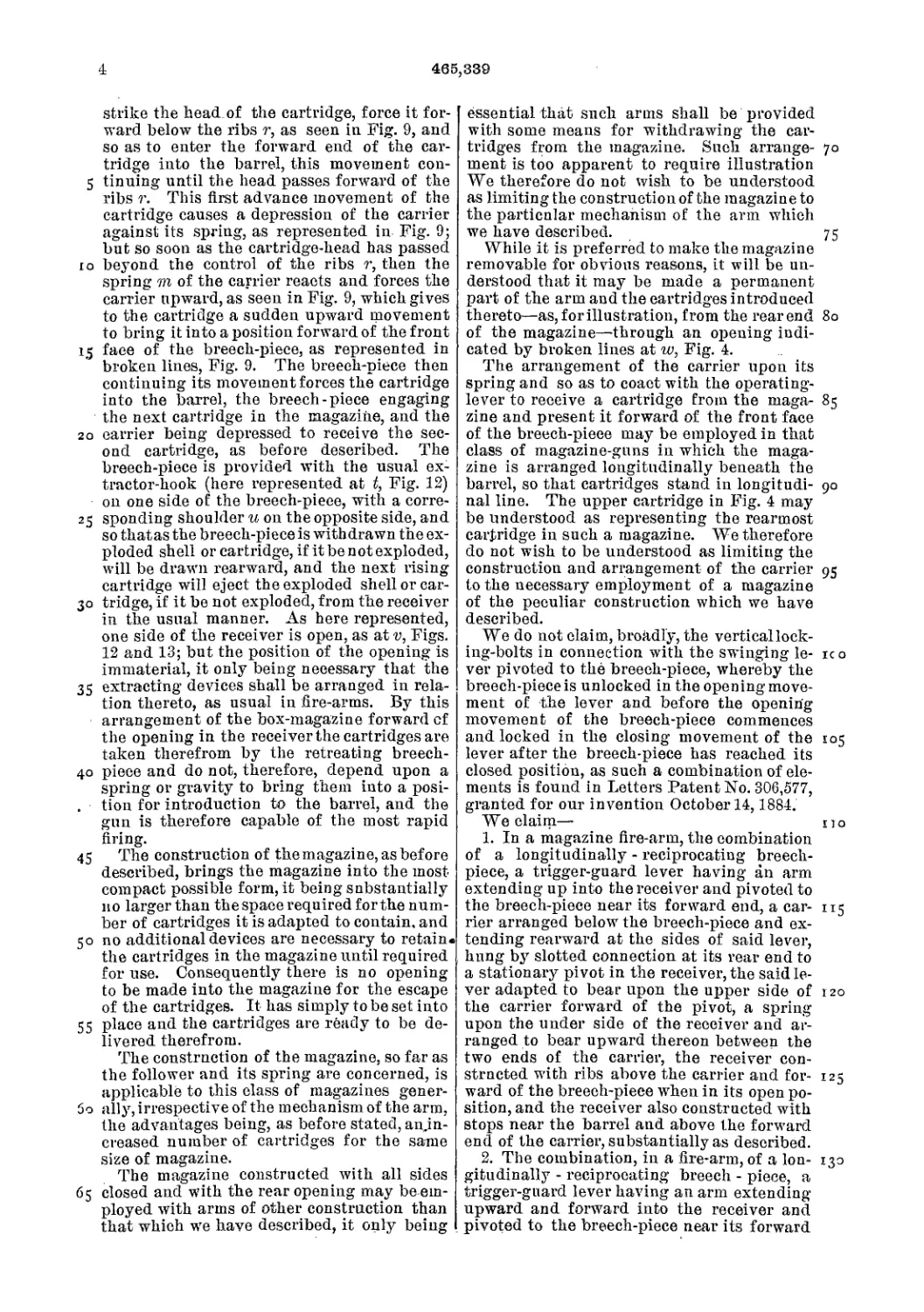
The breech-piece is provided with the usual
spring extractor-hook, L, above the firing-pin,
and upon the lower side of the firing-pin is
the usual shoulder, I, upon which the flange
of the cartridge will rest, as seen in Fig. 7. 80
m is the ejector, which is arranged at the for-
ward end of the firing-pin, and is in the form
of a spindle parallel with the firing - pin.
Around the spindle is a helical or other suit-
able spring,-n. This spring extends from a 85
a, shoulder near the forward end of the ejector
rearward toward the head of the lever G, and
so that when the parts are in their closed po-
sition the spring is relaxed. The head of the
lever G forward of the pivot forms a cam, 0, 90
which bears against the spring n, and so that
if the forward movement of the ejector be re-
sisted as the lever G is turned the spring will
be compressed, as seen in broken lines, Fig.
7. The ejector stands flush with the front face 95
of the breech-piece when in its closed posi-
tion, and against the head of the cartridge P,
the cartridge being held by the spring ex-
tractor-hook L upon the shoulder I below.
Kow, if in this condition the breech-piece be 100
drawn rearward, the shell retains its position .
with its head against the front face of the
breech-piece during such rear movement by
the action of the hook L, and because of the
shell standing within the cartridge-chamber 105
in the barrel. During the rear movement of
the breech-piece and the cartridge or shell
thereto attached the spring n is compressed
under the action of the cam 0 on the lever G,
thereby constantly increasing the bearing of no
the ejector against the head of the cartridge,
until in the rear movement of the breech-
piece the forward end of the cartridge es-
capes from the cartridge-chamber. Then the
action of the spring nforces the ejector for- 115
ward,throwing the lower side of the head from
the shoulder I, the forward end of the shell
upward, and so as to eject the shell or car-
tridge, as the case may be, from the arm. As
the movement of the ejector is only produced 120
by the compression of the spring, and not a
positive movement from the cam 0, the ejector
N returns as the breech-piece is closed against
the head of the cartridge, and whether or not
the cam 0 has relieved the spring from its 125
pressure.
The magazine is charged th rough a side open -
ing, B, in the receiver^ This opening is pro-
vided with a cover, S, arranged to slide longi-
tudinally in grooves r, (see Figs. 9 and 10,) 130
forward to open the receiver for the insertion
and rearward to close it. To make the closing
automatic, holes t Are bored into the forward
end of the receiver rearward and parallel with
306,579
3
the grooves г >*, and so that the grooves open
into those holes, as seen in Figs. 8, 9, and 10.
On the upper and lower side of the slide S is
an ear, w, which extends into the holes or
5 grooves t. These holes form substantially what
may be called ‘ ‘grooves, ’ ’ but broader than the
grooves r—that is to say, the groove in each
side of the opening is .contracted froih the in-
side outward, and into the enlarged portion
io from the forward end a helical spring, w, is
introduced against the ears u, and then at the
forward end of the receiver a plug, T, is in-
' troduced (may be in the form of a screw, as
shown,) against that end of the springs, com-
15 pressing the springs forcibly against the ears
u, and so that as the slide S is moved forward
the springs w will be compressed, and so that
their reaction, when free, will force the slide to
retnrn to. its closed position. The slide is
20 moved forward by the insertion of the point
of the cartridge pressed against it in the usual
manner of charging magazines through a side
or similar opening. By this construction the
cover-closing springs, as well as the guide jor
25 the cover, are entirely within the receiver,
and in rear of the front end of it, and so that
there is no opening from the receiver into the
forearm, as must be the case where the spring
of the cover is applied npon a spindle or
30 otherwise forward of the front end of the re-
ceiver.
• As a latch to hold the cartridges in the mag-
azine, a spring, W, is applied upon the opposite
side of the receiver, but, above the center of
35 the magazine, as seen in Fig. 10. This spring
overhangs the passage from the magazine onto
the carrier, and serves also as a continuation
of the magazine-tube for the control of the car-
tridge, and to hold it upon the carrier until it
40 has entirely passed from the magazine, as seen
in broken lines, Fig. 5. Before the cartridge
has passed entirely from the magazine onto
the carrier Y, as seen in broken lines, Fig. 4,
the head end has passed beneath lugs Z Z, one
45 on each side the receiver above the carrier,
but forward of the front face of the breech-
pieee in its open position, as seen in Fig. 4,
these lugs Z Z indicated in broken lines, Fig.
1. As the carrier ascends, as seen in broken
50 lines, Fig. 4, in the last part of the rear move-
ment of the breech-piece, it raises the cartridge
into a position in front of the breech-piece, the
point end of the cartridge freely passing the
spring W, and when raised the breech-piece is
55 moved forward, forcing the cartridge from the
carrier into the chamber, the head passing
from under the lugs Z. The spring W and the
lugs together serve to prevent the cartridge,
from being accidentally thrown or removed
60 from the receiver while the breech-piece is
open and before the carrier begins to rise, and
from that time the lugs Z Z serve to prevent
this accidental removal of the cartridge until
it be fairly entered into the chamber.
65 So far as the spring W serves as a latch to
retain the cartridge in the magazine, it per-
forms its office substantially as does a similar
spring in previous arms. It is thrown out of
its latching position in the movement of the
parts of the arm, so as to permit the last car- 70
tridge in the magazine to start rearward in
time to escape therefrom to pass onto the car-
rier, substantially as in previous arms, and
does not require particular description.
While we prefer to make the slot in the lever 75
upon the pivot which connects the bolts to the
lever, the slot may be at the pivot in the
breech-piece, as seen in Fig. 11. In this case
the downward or opening movement of the
lever performs its office npon the bolts to give 80
them a downward movement in advance of the
breech-piece, the slot at the forward end of the
lever riding back upon the pivot b in the
breech-piece until the forward end of the slot
comes in contact with that pivot, which is at 85
the time the bolts have arrived to such a posi-
tion that the incline on the forward edge of
the recess in the breech-piece may pass over
their upper ends, and as seen in broken lines,
Fig. 11. From that time the breech-piece 90
moves rearward with the lever. In» the re-
turning or closing movement the breech-piece
is moved forward under the influence of the
lever, say, to the position seen in Fig. 12. At
that time it is beyond the influence of the 95
lever because of the position of the slot with
relation to the pivot b. At this time the lever
tnrns upon that pivot b and throws the bolts up-
ward. Their noses, striking upon the inclines
at the for ward side of the recess in the breech- 100
piece, act to force the breech-piece from that
point forward into its closed position, and un-
til the bolts can rise into the recesses to their
extreme locked position, the essential feature
of this part of our invention being a direct 105
connection of the bolts to the lever and the
lever to the breech-piece, such connections'be-
ing ni'ade by means of a slot at one pivot or the
other, whereby the bolts are thrown into
their extreme locked position after the breech- 110
piece is closed.
We have not described the carrier or de-
vices for transferring the cartridges from the
magazine to a position in front of the face of
the open breech-piece, so that they may be 115
transferred to the barrel in the forward move-
ment of the breech-piece, as this mechanism
constitutes no part of this present invention.
Any of the numerous devices or carriers for
this purpose may be employed. 120
We have illustrated and prefer two bolts,
one upon each side of the breech-piece; but
it will be readily seen that one bolt will ac-
complish the object of the invention.
Instead of making the incline g on the 125
breech-piece, it may be made on the front face
of the bolt, as seen in Fig. 13, and accomplish
the same object, it only being essential to this
part of our invention that there shall be an
incline in front of the nose of the bolts, where- 130
by they may impart'the closing movement to
the breech-piece.
While we represent' in the illustration the
invention as applied to magazine fire-arms, we
’4
306,577
do not wish to be understood as limiting it to 1
such ar^is, as parts are applicable to single |
breech-loaders.
We do not claim, broadly, a vertically-mov-
5 ing locking-bolt to engage the breech-piece in
its closed position, as such, we are aware., is not
new; but we are not aware that a vertically-
moving locking-bolt has been directly and
positively hung to the lever and the lever di-
ip rectly hung to the breech-piece, which con-
struction is the essential feature of this part
of our invention.
We claim— .
1. In a fire-arm substantially such as de-
15 scribed, the combination of thelongitudinally-
movable breech-piece, the trigger-guard lever
extending up into the receiver and forward,
hurfgtothe breech-piece, a vertically-movable
bolt or bolts arranged in guides in the re-
20 ceiver, the breech-piece constructed with a
recess corresponding to said bolt or bolts and
with which said bolt or bolts will engage, the
said bolts hung by a pivot directly to said le-
ver in rear of and below the connection of the
25 lever with the breech-piece, one of said con-
nections slotted, whereby the descent of the
bolts is made during the first part of the move-,
mentof said lever and before the breech-piece
commences its opening movement, and said
30 bolts raised into their locking position after
the breech-piece is closed, substantially as de-
scribed.
2. In a fire-arm substantially such as de-
scribed, the combination of a longitudinally-
35 movable breech-piece, the trigger-guard lever
extending: upward into the receiver and for-
ward, hung to the breech-piece, a bolt or bolts
arranged in.vertical guides in the receiver
and in rear of the point of connection between
40 said lever and the breech piece, the said bolts
hung by a pivot to said lever, the connection
at one of the pivots slotted to permit the move-
ment of the bolts with the lever before the
breech-piece commences its opening move-
45 ment, and to return said bolts in advance of
the complete closing of the breech-piece, an
incline in front of the nose of the bolts, where-
by the last part of the closing movement of
the breech-piece is made by the ascent of the
50 bolts, substantially as described.
3. In a fire-arm substantially such as de-
scribed, the combination of a longitudinally-
movable breech-piece, the trigger-guard lever
extending up into the receiver and forward,
55 hinged directly to the breech-piece, the hinged
end of the lever constructed with a cam, Л,
projecting rearward therefrom, the firing-pin
F, constructed with; a shoulder, i, inclining
downward and forward corresponding to the
cam Л on the lever, said cam overhanging the 60
said shoulder, substantially as described,
, 4. In a fire-arm substantially such as de-
scribed, the combination of the longitudinally:
movable bolt D. the trigger-guard lever G, ex-
tending up into the receiver and forward, hung 65
to the breech-piece by a pivot, b, the vertical
bolt or bolts H, hung directly to said lever be-
low and in rear of the pivot b, the said lever
constructed with a cam, h, and the firing-pin
constructed with a shoulder, i, corresponding 70
to said cam Л, substantially as and for the pur-
pose described.
5. In a fire-arm substantially such as de-
scribed, the combination of the longitudinally-
movable breech-bolt D, the trigger-guard le- 75
ver G, extending up into the receiver, hung
to the breech-piece, and constructed with a
cam, 0, forward of and below the pivot by
which it is hung to the breech-piece, an Rect-
or, m, arranged below the firing-pin and par- 8c
allel therewith, and a spring, n, one end rest-
ing against said cam 0, the other end against
the ejector, and whereby the movement of said
ejector is produced through said spring, sub-
stantially as described. 85
6. Inamagazine fire-arm, the receiver, con-
structed with the opening R to the magazine,
the cover 8, arranged to move longitudinally
in grooves or guides r in each edge of the open-
ing in the receiver* the said grooves opening 90
into an enlargement, t, and the cover con-
structed with ears « at or near its rear end,
extending into said enlargement, with springs
w arranged in said enlarged parts of the
groove, one end supported near the forward 95
end of the receiver as resistance, the other end
bearing rearward against the said ears on the
cover, substantially as described.
7. In a magazine fire-arm, the combination
of the longitudinally-movable breech-piece, a ico
carrier arranged to receive a cartridge from
the magazine and raise it to a position be-
tween the front face of the open breech-piece
and the cartridge-chamber, the spring W, ar- -
ranged longitudinally in the receiver to over- 105
hang the cartridge at the month of the maga-
zine, and lugs Z Z on the sides of the receiver,
projecting inward above the earner and for-
ward of the front face of the breech-piece in
its open position, substantially as described.
JOHN M. BROWNING.
MATTHEW S. BROWNING.
Witnesses:
ObsojtRisee,
1). W. Felshaw.
(No Model.)
J. M. & M. S. BROWNING.
PETERS. Ptiolo LitKographor, Waihingidn. D
United States Patent Office,
JOHN M. BROWNING AND MATTHEW S. BROWNING, OF OGDEN, UTAH
TERRITORY.
MAGAZINE-GUN.
SPECIFICATION forming part of Letters Patent No. 312,183, dated February 10,18S5.
Application filed Vlarch G, 1884. Renewed December 13, 188-1. (No model.)
5
ю
15
20
2 5
Зо
35
4о
45
To all whom it may concern :
Be it known that we, John M. Browning
and Matthew S. Browning, of Ogden, in the
Territory of Utah, have invented a new and use-
ful Improvement in Magazine-Guns; and we
do hereby declare that the following is a full,
clear, and exact description of the same.
Our invention relates to breech-loading fire-
arms, and is mainly applicable only to maga-
zine-arms.
The improvement relates more particularly,
first, to the operating-lever, which is made to
serve the purpose of locking the breech-clos-
ing bolt, and, secondly, to the carrier, by
means of which the cartridges are raised into
line with the bore of the barrel.
The leading features of the invention and
the subordinate details are fully described
hereinafter, aud are specifically indicated in
the claims.
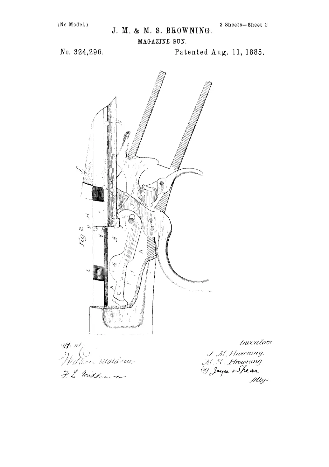
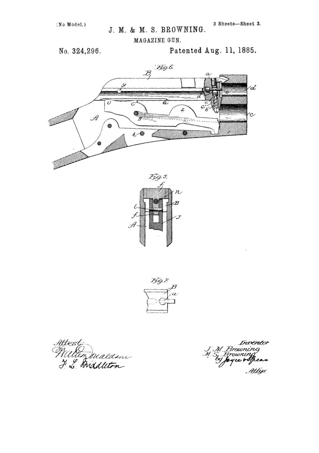
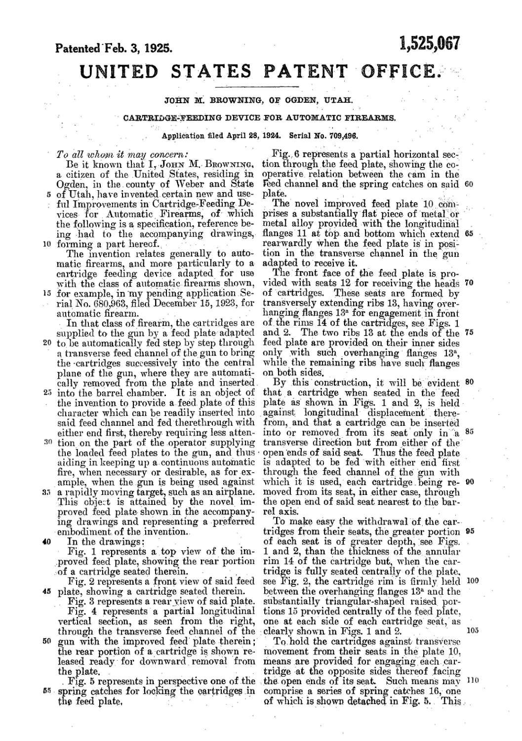
In the drawings. Figure 1 represents a ver-
tical longitudinal section of the receiver and
breech-closing bolt, with part of the magazine
and barrel, the contained and contiguous parts
being in side elevation. Fig. 2 shows the same-
view with the, parts in different positions.
Fig. 3 is a plan view of the carrier.
The first feature of the invention is the slid-
ing block on which the operating trigger-guard
lever is pivoted, which serves to move the
bolt and to lock it in place. This lever is
shown at b V, the former noting the upper
part, or that within the receiver, and the lat-
ter that outside or below the receiver. The
upper encl of this lever is pivoted to the bolt
A by a pin, c, so as to turn on the pin when
the lever is raised from the position of Fig.
1 to that of Fig. 2. It is pivoted closely to
the bolt, so that there is no movement upon
the pin except that of turning. The firing-
pin 1 passes through the bolt above the pivot
c, the forward end being reduced to leave a
shoulder, 2, which bears against the bottom
of a recess within the lever. The lever is piv-
oted upon a sliding block or swivel, d, this
block being equal in width to that of the lever.
The block is bored, as shown at e, to receive
a spring, and at its forward end is slotted
transversely to receive a pin, /, set in the walls
of the receiver. The spring bears against the 50
pin /, and tends to push the block to the rear.
The lever is formed with the shoulder i be-
hind its pivot, said shoulder being preferably
made npon a curve struck from the pivot c.
When the lever is in position shown in Fig. 1, 55
this shoulder bears against a corresponding-
seat in the rear part of the receiver, and be-
ing pressed rearward by the spring, locks the
bolt securely in its place. The firing-pin,
when the lever is in position shown in Fig. 1, 60
rests in its advanced position with the shoul-
der 2 against the bottom of the socket or cav- .
ity. The first effect of the forward movement
of the lower part of the lever is to start back
the firing-pin. and the lever holds this slightly 65
retracted until the bolt is returned to its seat
in the breech. The pivoting-block d is pressed
forward when the upper part begins to move
backward, and the shoulder i of the lever
drops from its seat, thus unlocking the bolt. 70
Further movement of the lever throws back
the bolt to the position shown in Fig. 2, at the
same time cocking the piece. By this con-
struction great force is applied to the bolt with
a minimum of friction. 75
The carrier is of special and improved form.
It is shown in side elevation in Figs. 1 and 2,
and in plan view in Fig. 3. It is pivoted at Ji
in the chamber of the receiver, and its for-
ward end is adapted to swing up from the po- 80
sition shown in Fig. 1 to that shown in Fig.
2. It is made in two parts, as shown in Fig.
3, the part m constituting onesideand the part
n the other side. These parts are connected
by a bolt, Z, which is fixed to one part and is 85
loose in the other. Each part is provided
with an upwardly-projecting ear, A:, the upper
parts of which ears incline slightly inward to
hold the cartridge. The rear ends of the sides
are inclined also slightly inward, as shown at go
0 0. The two sides are pivoted separately,
each turning upon a small stud set into the
walls, and the pivoting is sufficiently loose to
allow the forward ends of the carrier to be
slightly spread or narrowed. The lever moves 95
in the space M in the rear part of the carrier,
between the sides, and as it reaches the in-
clines о 0 on the rear ends of the two parts of
9
312,183
5
io
i5
20
25
30
35
the carrier it presses them apart, and thus
causes the front ends to approach each other to
grip the cartridge. As soon as the lever A is
returned to carry forward the cartridge and
close the breech it leaves the inclines о о, and
thus permits the front ends of the carrier to
spread and release the cartridge. The forward
end is adapted, when spread, to receive the
cartridge, and when closed to retain the car-
tridge by means of the inward inclination of
the ears 1c. The rear ends of the carrier ex-
tend upward,and are provided with shoulders
4, which are struck by projections 5 on the
front ends of the bolt when the bolt is in the
latter part of the movement to the rear, and
after it has pressed between the inclines о о, to
cause the carriers to grip the cartridge. This
throws up the front of the carrier end in the
ordinary manner. An ordinary retractor, 3,
serves to draw back the empty shell. The
ejector consists of the stud 6, which fits in a
hole bored in one side of the bolt, in which it
is held by a pin. It has free but limited move-
ment, and just before the bolt reaches its rear-
most limit the end of this stud strikes against
the shoulder 4 and is thrown forward into po-
sition shown in Fig. 2. As the forward end
of the shell has at that time cleared the bar-
rel, it is thrown out by the projecting end of
the stud. At the same the projection 5 has
caused the forward end of the carrier to rise
with the cartridge received from the magazine.
It is held up by pressure of the magazine-
spring against its forward end. Luring the
rise of the carrier the cartridge is gripped se-
curely by the inward movement of the walls,
caused by the rearward movement of the part
b of the lever pressing between the inclines
о o, as heretofore explained. This gripping
takes place just before the rise of the carrier. 40
The reverse movement of the carrier, w’hich
brings forward the bolt and drives the car-
tridge to its seat, at the same time throws down
the carrier, ready for another cartridge. The
last part of the movement of the lever locks 45
the bolt in place and lets the end of the firing-
pin rest upon the cartridge.
We claim as onr invention—
1. In a breech-loading fire-arm, and in com-
bination, a bolt for closing the breech, and a 50
lever connected to the bolt and pivoted on a
sliding block provided with a spring, said le-
ver having a seat in the receiver, whereby it
locks the bolt, all substantially as described.
2. In a breech-loading fire-arm, and in com- 55
bination with a horizontally-moving breech-
closing bolt and operating-lever pivoted there-
to. a carrier composed of two parts pivoted
separately,for vertical and slight lateral move-
ment, the front ends of which parts are pro- 60
vided with ears adapted to grip the car-
tridge, and the rear ends formed with inclines
adapted to the lever which is located between
the two parts, all substantially as described.
In testimony whereof we have signed our 65
names to this specification in the presence of
two subscribing witnesses.
JOHN M. BEOWNING.
MATTHEW S. BROWNING.
Witnesses:
D. Johnson,
D. W. Felshaw.
3 Sheets—Sheet 1
iNo Model.)
J. M. & M. S. BB.OWNING
MAGAZINE GUN
No. 324,296. Patented Aug. 11, 1885.
(No Model.)
3 Sheets—Sheet S
J. M. & M. S. BROWNING.
MAGAZINE GUN.
No. 324,296.
Patented Aug. 11, 1885.
3 Sheets—Sheet 3.
No Model.)
J. M. & M. S. BROWNING.
MAGAZINE GUN.
No. 324,296.
Patented Aug. 11, 1885.
/'/ГХУг/сГ
United States Patent Office.
JOHN M. BROWNING AND MATTHEW S. BROWNING, OF OGDEN CITY, UTAH
TERRITORY, ASSIGNORS TO THE WINCHESTER REPEATING ARMS COM
PANY, OF NEW HAVEN; CONNECTICUT.
MAGAZINE-GUN.
SPECIFICATION forming part of Letters Patent No. 324,296, dated August 11, lt}85.
Application filed Marell 5, 1883. (No model J
To all whom it may concern:
Be it known that we, John M. Browning
and Matthew S. Browning, of Ogden City,
in the county of Weber and Territory of Utah,
5 have invented a new and useful Improvement
in Magazine-Guns; and we do hereby declare
that the following is a full, clear, and exact
description of the same.
Our invention relates to that class of brecch-
io loading fire-arms in which the breech piece or
bolt is arranged to move back and forth in an
axial line with the bore of the barrel, and is
operated by a finger-lever extending below the
receiver and forming the trigger-guard.
15 The main part of the invention is adapted
especially to magazine-guns, but is also appli-
cable to single loaders. In connection with
this main part we have also shown subordinate
features, all as hereinafter fully explained.
20 The principal part of the arm is the device
for locking the bolt when the breech is closed,
the object of this being to provide an inde-
structible dead lock for the bolt. The second
feature consists of an improved construction
25 of ejeclor. The third feature relates to the
construction of the carrier, and the subordi-
nate lealiires are explained hereinafter.
In the accompanying drawings, Figure 1
shows a central longitudinal vertical section
jo of the receiver and bolt of the arm with its ad-
jacent parts, and witl^ the working parts in
side elevation, the figure showing the breech
closed. Fig. 2 shows a like section with the
working parts in side elevation and with the
35 breech open.. Fig. 3 is a top view of the re-
ceiver and bolt with its adjacent parts. Fig.
4 is a plan view of the carrier. Fig. 5 is a sec-
tional cut on line x z, looking from point 1,
Fig. J. Fig. (> is a side view with the wall of
40 the reeei ver taken away, showing the extractor
and the improved carrier for cutting otf the
cartridges in the magazine or stopping the one
next to the one coming into the carrier at any
point, desired. Fig. 7 is a detail plan view of
45 the extractor shown in Fig. 6.
In these drawings, the receiver A with its
bottom plate, 6, and the magazine e and bar-
rel d are shown in their usual relation to each
other. The bolt В is arranged to be moved
I longitudinally from the rear end of the barrel, 50
in order to open, and toward it to close, the
breech. The bolt slides in guiding-grooves in
the usual manner. The upper part of the bolt
is chambered out to receive the locking-block
f. This locking-piece, in connection with the 55
lever, locks the bolt in position to close the
breech. The main part of the locking piece
is narrow, as shown in plan view, and/is en-
larged at the forward end, the chamber in
the bolt being formed accurately to receive it. 60
The piece is pivoted at its rear end within the
bolt by a pivot, g. The front end of the lock-
ing piece is formed on a enrve struck from this
pivot <7, and the front wall of the chamber in.
the bolt has a corresponding curve, so that the 65
locking-piece fits accurately against it when
said piece is down in locking position.. The
wide side of the forward end of the locking-'
piece extends laterally below the bolt and fits
accurately into a rec-css, i, cut into the walls 70
of the receiver on the arc of a circle struck
from the same, pivoty. This recess in the wait
extends down to or near to the lateral guiding-
grooves of the bolt, and when the locking-
piece is down the lateral wings or extension^ 75
of its forward end extend down near to thfs
groove. The forward end of the locking-piece
has sufficient upward movement to cause the
lateral extensions to clear the lateral recess.
The lacking piece is pivoted to the lever J 8q.
by a pin, ?. The lower part of the locking-
piece is made thin, and extends between the
split end of the lever. The pin passes snugly
through the end of the lever and through a
slot in the locking-piece, this slot being long 85
enough to provide for the necessary lost mo-
tion in the operation of the parts. The lever
J is pivoted at к in the receiver. Its front
end fits against the bolt on an arc. of a circle
formed from the joint-pin k, and the rear of 90
the lever is also formed on an arc of t he circle
struck from the same pin and bears against a
corresponds ugly-shaped portion of the abut-
ment of the bottom plate.
The parts arc so adjusted to each other that 95
as soon as the bolt is brought to itsscatin the
breech the lateral extensions of the end of the
locking-piece are in line with the recess i, and
2
324,296
5
io
'5
20
25
3°
35
4°
45
50
55
6o
65
Fig. 2. Another pin//', is placed in the fin-
ger-lever in such position that when the lever
is thrown back the front end of pin q' will 70
press against the rear end of the pin q. The
latter pin is set in the bolt so as.to project
from its face to one side of its center. The
pin </" isprovided with a spring, as at 5, which
keeps it pressed outward against the pin in 75
the bolt, and this pressure beingexerted upon
the shell or cartridge head near its edge will
force the shell to one side and slightly under
the overhanging flange of the receiver, and
thus hold it down until the carrier begins to 80
rise, the spring while exerting this pressure
being slightly compressed. When this latter
action takes place, the shell or cartridge will
be drawn from under the side of the receiver
and lifted up slightly. The spring ejector-pin 85
I q" will then exert its whole force, and its rear
end will also strike against the hammer, as
shown in Fig. 2, and the shell will be thrown
from the piece. During this action the shell
is held in the usual manner by the extractor 90
upon its upper edge.
Our improved carrier is designed not only
to clamp the cartridge, but also,in connection
with the special construction of the beveled
shoulder и upon the side of the bolt, it is de- 95
signed to stop the next cartridge in from of
the one moving upon the carrier, and to pre-
vent it from following the first upon the car-
rier. Otherwise it would lock the currier and
prevent it from rising. This is liable to happen ico
where a cartridge is used of too little length.
The carrier is composed of two parts, r and
s. These are pivoted to the receiver by two
short screws passing through their rear ends.
The rear ends also extend upward and have 105
shoulders, as shown at e, these shonlders
being arranged to be struck by the shonlders
c' on the forward end of the bolt in the usual
manner. The sides are also provided with
upwardly-extending wings 2, adapted to grip nc-
the cartridge when the sides are brought to-
gether. The rear end of the part s also ex-
tends back and up, as shown at v, entering
slightly into a recess in the under side of the
bolt. This recess termi nates at the front in a 115
beveled shoulder, w, which is intermediate be-
tween the shoulder c' on the bolt and the pro-
jection v on the carrier. The shoulder n acts
upon the projection v to elevate the carrier
sufficiently to block the entrance thereto, and 120
the shoulder o' in the continued movement of
the bolt acts upon the projection c to elevate
the carrier and cartridge carried thereby to
the.bore of the gun. The distance between и
and v is of course less than that between F 125
and c, in order to give the Successive move-
ments to the earner. A screw-pin, 3, passing
through the sidepieces diagonally,is made fast
to the part s, and fits loosely into the part r.
The forward ends may be fitted to each other 130
by inclined faces, as shown at 1. The part r
is slotted where it is pivoted to the receiver,
as shown in Fig. 2. The upwardly extension
I on the part r is farther forward when the car-
further moi ement of the lever brings down
the locking-piece with these extensions in the
recess i. At the same time the rounded bear-
ings ou the lever fit against the abutment in
the bolt and the bottom plate so that the bolt
is securely locked in place by an indestructi-
ble lock.
In order to hold the breech closed, a, spring
may be applied in various ways. We have
shown a convenient form in Fig. 1, for which
the locking-piece is bored longitudinally from
the rear and a spring, u', inserted, the hole be-
ing stopped by a plug, r. The front end of
the spring bears against the bottom of the
hole and the rear end against a pin, w. The
pin passes through the bolt and through the
locking-piece, the hole in the locking-piece
being elongated to allow the necessary move-
ment of the locking-piece. The elongated hole
may be grooved and the arc of a circles! ruck
from the point fj, ami as the front eml of the
piece is raised the spring is compressed by
lhe movement of the piece on the pin w, the
spring thus having the effect to hold the front
end of the locking-piece continually down,
and with it the. lever to which it is connected.
The hammer m is arranged tostrike the pin
•n, contained in the locking-piece, and adapt-
ed to slide with a limited movement in said
piece, with its front end projecting, when
pressed forward, slightly beyond the front end
of the piece. When the* locking piece is down
in position, which, as before explained, occurs
when the breech is closed, the pin n is in line
with the firing-pin о in the front end of the
bolt,-and it is only when the parts are in this
position, as shown in Fig. 1, that the blow
of the hammer can be transmitted to the. car-
tridge.
The bolt is adapted to be used with any or-
dinary extractor—for example, as that shown
in Fig. 1; but we have devised an improved
form which we purpose to use with this gun.
This form is shown in Figs. 6 and 7. The
front end of the bolt is bored out to receive
the shank a of- the extractor. This bore is
slightly inclined, the lower part being a little
forward of the upper part, which causes the
extractor to hug more closely to the shell when
the bolt is drawn back.
.The hole fitted to the reduced end of the
ejoetor-shank is preferably first formed by
goring a smaller hole, which is then enlarged
from both ends, leaving a shonlder or rib, e.
The shank is formed with a slot, d', adapted
to receive the firing pin and to permit the
necessary vertical niovement of the extractor.
The extractor is drawn down by means of a
spring,/;', the upper ends of which rest against
tlie shoulder c and the lower against a nnt,
which gives it a proper tension. The plan
view, Fig. 7, shows the relation of the ejector
and firing-pin.
An ejector-pin, q, is set in the front end of
the bolt in an inclined position, and has suit-
able niovement, so that it mayr advance be-
yond the face of the locking-bolt, as shown in |
ricr is down than the part «, so that when the I
bolt moves back it strikes the shoulder on the [
part r first, and the part .shaving nolongitudi- |
nal movement on its pivot the part r is car- i
5 ried back, and by reason of the inclination of
the pin 3 the forward ends arc brought to-
gether, clamping the cartridge on the carrier;
but this clamp will be released as soon as the
bolt begins to move forward.
ic In the operation of the gun,when thebvceeh
bolt is drawn back the incline и is caused to
strike against the rear upper end of the car-
rier, moving the forward end up sligh tly,so as
to obstruct the passage of the next eartridge
15 upon the carrier. It is held in this position
until the projection on the holtstrikesthe pro-
jection on the carrier and throws the carrier
up, bringing the cartridge into line with [he
bore of the gun.
20 The operation of the gun is as follows; Sup-
pose there is a cartridge in the barrel and the
magazine is loaded and breech closed, the
breech is opened by pressing thclever forward
juthe usual manner. The first effect of this
25 movement is to raise the front end of the lock-
ing-piece and this unlocks the bolt. The lever
through the locking-piece carries the bolt
back, the extractor being engaged with the
flange of the eartridge and drawing it back,
30 at the same time sliding back on the carrier
from the magazine. The hammer has been
forced back to full cock and caught by the
trigger. When near the limit of the back-
ward movement of the bolt.theshoulder on its
35 front end strikes the upward extension of the
part r of the carrier and slides saidpart "back-
ward,causing the carrier to grip the cartridge,
holding it firmly. Further movement of the
bolt causes it to strike the shoulder on the
40 part e, and the whole carrier is raised till the
forward end of the cartridge is in line with the
bore of the barrel. At the same time the
ejector-pins have come into line with each
'other, and are pressed forward by striking
45 against the hammer, so that the forward pin
is forced out, thus throwing out the shell or
cartridge. The movement of the lever being
reversed, it first opens the carrier by releas-
ing the partr. Continued movement causes
50 the bolt to for > the cartridge from the carrier
into the barrel, and then throw down the car-
rier. to receive Another cartridge from the
magazine. Finally,it draws the locking-piece
into place. Thisleaves thejfirin'g-pins in line,.
55 and the gun is ready to fire,
It will lie observed that the gun cannot be
discharged until the breech is closed and
locked, as the pins do not come into line until
the locking has been effected.
60 We claim as our invention—
1. In a magazine-gun, the combination, with
a sliding bolt, of a chamber therein, a lock--
ing-piece fitting within said chamber and
pivoted to the belt at the rear end thereof,
65 lateral extensions on said locking-piece adapt-
ed to fit into recesses in the sides of the re-
ceiver, and an operating-lever to which the
said locking-piece is pivoted, substantially as
described.
2. In a magazine-gun, the combination, with 70
a sliding bolt, of a chamber in the top thereof,
a locking-piece pivoted within said chamber
to the bolt, lateral extensions on the forward
end of the locking-piece adapted to corre-
sponding recesses in the walls of the receiver, 75
and an opera! ingle ver connected to said lock-
ing piece by a pin and slot connection, sub-
stantially as described.
3. In a magazine-gun, and in combination
with the recessed side walls of the receiver 80
and the sliding bolt having a chamber there-
in, the locking-piece f, pivoted within the
said chamber at the rear end thereof and
having lateral extensions on its forward end
adapted to the recesses of the receiver, the 85
operating-lever pivoted to the said locking-
picce at the forward end thereof, and aspring
contained in said locking - piece adapted to
keep the forward end down, and through it
the lever, substantially as described. 90
4, In combination with the sliding bolt, the
firing pin made in two parts, one of said parts
being carried in the forward end of the said
bolt, the locking-piece fitted to a recess in the
sliding bolt and carrying the other part of the 95
firing-pin, and the operating-lever, all the
parts being constructed and arranged where-
by the section n of the pin is moved out of
alignment with the section 0 when the breech
begins to open, and is in alignment therewith rco
when the breech is fully closed, substantially
as described.
5. In a magazine gun, the combination,with
a sliding bolt, operating-lever, and extractor,
of the ejector-pins g r/, one of said pins being 105
carried in the sliding bolt and the other in
the operating-lever, and adapted to operate in
connection with each other in the manner de-
scribed.
6. In a magazine-gun, the combination, with no
a sliding bolt and operating-lever, of a two-
part carrier provided with extensions on the
upper rear portion thereof adapted to be
struck by shoulders on the bolt, and exten-
sions on the upper front portion thereof adapt- 115
ed to grasp the cartridge, one part of said car-
rier beingpivoted on a pin; projecting through
the wall of the receiver and passing through
a slot in the rear thereof, and the other] part
beingpivoted on a similar pinto turn With* 120
.out sliding, all substantially as described.
7. In a magazine-gun, tlic combination,with
a sliding bolt and operating-lever, of the|two-/
part carrier r s, the diagonal screw or pi n 3, "
and the extensions 2 in the upper front por- 125
tion of said carrier, whereby, when the bolt is
retracted, the part r of the carrier is moved
longitudinally and laterally on the pin 3 to-
ward the part e to grasp the cartridge, allsub-
stantially as described. 130
8. Ina magazine-gun, the combination, with
Я eliding block and operating-lever, of a two-
part carrier, one of said parts being provided
with a rear extension, r, projecting upward
4
324.296
in Io a recess in the bolt, the said recess ter-
minating in a shoulder, u, which is adapted
to strike anddepressthcextension v toslightly
raise the forward end of the carrier to arrest
5 the eartridge next to that on the carrier,
and the projection c', on the forward end of
the bolt, adapted in the continued movement
of the bolt to act upon the projection c above
the pivotal point of the carrier to elevate the
to said carrier and present the cartridge to the
bore of the gun.
9. In a magazine-gun, the combination, with
a sliding bolt, of an extractor having a shank
fitted to a recess extending downward through
15 the end of the bolt and aspringonsaid shank,
substantially as described.
10. In a magazine-gun, tire combination,
with a sliding bolt, of an extractor, a shank
extending at an angle thereto and fitted to
an inclined hole in the bolt end, and a spring 20
on said shank, substantially as described.
In testimony whereof we have signed onr •
names to this specification in the presence of
two subscribing witnesses. ’ j
JOHN M. BROWNING.
MATTHEW S. BROWNING.
Witnesses:
Louis Farr,
D. W. Fei.shaw.
•No Model.)
2 Sheets—Sheet 1
J. M. & M. S. BROWNING.
MAGAZINE FIRE ARM.
2 Sheets—Sheet 2.
No Model.)
J. M. & M. S. BROWNING.
MAGAZINE FIRE ARM.
United States Patent Office.
JOHN M. BROWNING AND MATTHEW S. BROWNING, OF OGDEN CITY, UTAH
TERRITORY, ASSIGNORS TO THE WINCHESTER REPEATING ARMS COM-
PANY, OF NEW HAVEN, CONNECTICUT.
MAGAZiNE FIRE-ARM.
SPECIFICATION forming part of Letters Patent No. 324,297, dated August 11, 1885.
Application filed May 2G. 1885. (No model.)
To all whom it may concern:
Be it known that we, John M. Browning
and Matthew S. Browning, of Ogden City,
in the county of Weber and Territory of
5 Utah, have invented a new and useful Im-
provement in Magazine-Guns; and we do
hereby declare that the following is a full,
clear, and exact description of the same.
Our invention relates to breech-loading and
i о magazi ue fire-arms, a part thereof being adapt-
ed to be used without the magazine.
The first part of the invention relates to the
firing pin, and has for its object to provide a
simple mechanism impossible to-explode the
15 cartridge until the breeoh is closed.
The object of the second part is to provide
an improved ejector mechanism, and of the
third part to improve the carrier mechanism.
In the accompanying drawings, Figure 1 is
20 a central longitudinal section through the
chamber of the pieceand the breech-bolt, the
breech being closed. Fig. 2 is a similar view,
showing the parts in the position when the
breech is open. Fig. 3 is a top view.of the
25 carrier. Fig. 4 isa transverse section through
the carrier and the walls of the receiver. Fig.
5 represents* the face of the bolt.
We first proceed to describe the improved
firing-pin and its connections.
30 In these drawings, A represents the breech-
bolt in line with the bore of the gun. It is
operated bjr means of a lever, 2, pivoted to a
swivel, 3, and $0 the bolt by a pivot, 14. The
end of the lever bearing upon the bolt is
35 rounded and bears against the seat in the bolt
in which it turns. It abuts with a like seat
against the swivel,, and the swivel is pivoted
upon an' abutment in the rear part of the
chamber. The firing-pin 1. is placed within
40 the bolt, which is bored out to receive it. The
pin is made small from its forward end back
to the shoulder 11, and the enlarged part in
rear of this shoulder is provided with a notch,
12, on its under side. The small portion of
45 the firing-pin is flattened on its sides and
passes through the lipper part of the lever 2
and also through the upper part of the safety-
lever 7, hereinafter explained, both of which
arc slotted to receive the pin. The safety.
locking-lever 7 is. pivoted at its forward end 50
to the bolt by a pivot, 13, its-rear end being
slightly upturned and fitted to the notch 12
in the enlarged part of the firing pin. It has
also an upward extension, 16, forming a shoul-
der a little in rear of the pivot 13. A spring, 55
8, is placed upon the firing-pin, its rear end
bearing upon the shoulder 11 and its front end
upon the projection 16. The front end of the
safety-lever 7 is struck by the lever 2 in the
latter part of the movement of said lever to 60
close the breech, and the latter part of said
movement, moves tile safety-lever sufficiently
to throw the lower end out of the notch 12.
From the above description it will be clear
that when the lower end of the lever 2 is pressed 65
down to open the breech it will drop away
from the forward end of the safety-lever 7, and
the spring 8, pressing a little above the path
of the safety-lever, will tend to th row the rear
endupwardagaiustthefiring-pin. Now, when 70
the hammer is drawn back the spiral spring
8, by pressing upon the. shoulder 11 of the
firing-pin, will press the firing-pin back, and
as soon as the notch 12 passes the rear end of
the safety-lever this end will snapnp into the 75
notch 12. This movement is sufficient to draw
the front end of the firing-pin into the bolt,
away from the cartridge, and it will be appar-
ent that the gun could not be fired in the po-
sition shown and described until the breech 80
is again closed and the lever2 brought up into .
position in contact with the forward end of
the safety-lever.
Our improved ejector is shown at 20. It is
located in the forward end of the bolt ou one 85
side of the center thereof, sufficiently to avoid
the firing-pin. Its rear cud extends down-
ward and backward diagonally to the bottom
of the bolt. Its lipper end, 21, is bent up-
ward past the center of the bolt, and lies in a 9c
recess in the face of the bolt. The lower end
projects slightly, so as to be in proper posi-
tion to be struck by shoulder 22 on the for-
ward end of the lever when the said lever is
moved and the breech-bolt is forced to its 95
rearward limit, and thus the.rear end of the
ejector is pressed upward and forward. The
head of the cartridge being held by the upper
2
324,29?
edge, this pushing forward of the ejector
throws the shell out.
The hammer is of ordinary construction.
(Indicated at 5.)
5 The trigger 4 is located in the slotted rear
end of the swivel, and is pivoted upon the
same pin.
The carrier is composed of two parts, as
shown more clearly in Figs. 3 and 4. These
io two parts, except at the forward end, have
comparatively thin sides, chamfered on the
outside from near the upper to the lower edge,
as shown in Fig. 4. Thefront partof theside
pieces are thicker, as shown atp <?, theformer
15 being shorter, and the latter extends across
the front of the former the entire width of the
carrier. These parts are connected by a pin,
r, formed upon or set into one of the pieces
and projecting loosely into the other. The
20 parts are fitted to each,other so as to allow
them to rock slightly upon the pin r, to cause
the forward edges to advance toward and
recede from each other. The carrier is piv-
oted in the receiver by a pin, 0, passing
25 loosely through the sides of the carrier, so
as not to interfere with the above-described
movement of the sides, the pin being set
in the walls of the receiver. Thus the car-
rier swings upon this pin vertically, and the
30 sides rock slightly also. Upon the lower rear
partof the carrier sides are small inclined pro-
jections 1t, of such positionand of such shape,
as shown in Figs. 1, 3, and 4, that when the
lever is in the position shown in Fig. 2, be-
35 tween the sides of the carrier, it will bear
against the projections tt, and thus throw out
the lower sides of the carrier. This tips in the
upper forward sides and causes the carrier to
grip the cartridge. Tire forward end of the
40 carrier is adapted to'receive the cartridge, be-
ing hollow, as shown iu Fig. 3, and provided
with beveled ears ss, which damp.the car-
tridge. The upper end of the lever 2 in its
forward position passes between these ears
45 and separates the npper sides and ears, ready
to receive another cartridge. The sides of
the carrier at their rear ends are provided with
upward projections 17 17, and adapted to be
struck by the shonlders 9 and 10 on the under
50 side of thesliding bolt A. The position of the
shoulder 9 is such that they strike the projec-
tion 17 as the breech-block, approaches its
rearmost limit, and the projections 10 are
adapted to throw down the carrier as the bolt
.55 closes the breech.
The novelty Of this construction.consists in
the lateral rocking of the sides of the carrier.
In the operation of the arm the magazine is
loaded at the side through an ordinary spring-
60 trap. A cartridge or shell being in the cham-
ber, suppose the lower end of the lever to be
thrown forward. The first effect of this move-
ment will be to slide the bolt backward and
begin to force the hammer to the full-cock
65 notch. At the same time the forward portion
of (lie lever drops away from the safety lever
7, and the spring 8 then begins to exert its
force. The first action of the spring is to
press the firing-pin to its rearward limit of
movement, thereby drawing the forward end 70
of said pin even with or slightly within the
face of the bolt, and by this movement, also,
the notch 12 passes the rear end of the safety-
lever, which, through the spring acting’upon
the shoulder 1G, is forced into the notch, as 75
shown in Fig. 2. A further movement of the
lever forces the hammer to the full-cock notch
and carries the breech-bolt back until the car-
tridge or shell is drawn from the barrel. The
ejector is then struck by the shoulder 22 on 80
the lever as the upper end of the latter turns,
and is forced quickly outward, which has the
effect of ejecting the shell or cartridge from
the chamber. The same movement of the le-
ver has also spread the lower edges of the car- 85
rier sides and caused the ears s to grip the
cartridge, which has been forced back by the
magazine-spring onto the carrier. The last
part of the backward movement of the bolt
also, by means of the shoulders 9 and 17 on 90
the bolt and carrier, respectively, forces up
the forward end of the carrier and presents
the cartridge to the bore of the barrel. The
return movement of the lever slides the bolt
forward and at the same time relieves the 95
pressure from the ejectdr-pin, which .is then'
free to drop back into its place flush with the
face of the bolt. The face of the bolt then
strikes the head of the cartridge (the firing-
pili being still held within the bolt by the юс
safety-lever) and pushes it into the bore of the
barrel, while the lever spreads the sides of, the
carrier. The last part of this' return move-
ment throws down the carrier by the means
before described and brings the forward por- 105
tion of the lever 2 to bear upon the safety-
lever 7, thereby forcing its rear end from the
notch 12 and leaving the firing-pin free to be
acted upon by the hammer.
In the bottom plate of Fig. 1 we show a de- no
vice which we term a “safety-valve,” It can
be arranged in different ways and in any part
or piece of the gun best suited for it. Some-
times the head of a cartridge blows off in firing,.
and if the end of the bolt does not fit exactly 115
against the barrel there is a great escape of
gas into the breech,which is liable to swell or
burst the receiver and disable the gun. By
this arrangement, no matter how much gas
escapes into the breech, this valve opens aud 120
allows it to escape without injury to the arm.
The following is a description: In Fig. 1 is
shown a valve, 23, swinging on the pin 30. It
is arranged to swing outward. At 15 is rep-
resented a spiral spring arranged to hold the 125
valve closed. The bottom plate is cut through
into theinterior. It is evident that when there
is any gas-pressure on the inside the valve
will be blown open, and when-the pressure is
gone the spring will close it again. 130
We claim as bur invention—
1. The combi nation, in a brcech-loading fire-
arm, of thesliding bolt, a firing-pin having an
enlarged rear end and shoulder, 11, said pin be
324,297
3
5
ic
15
20
25
30
i ng fi tted to the longi tud i nal bore of the breech-
bolt, a lever, 7, pivoted to the bolt and hav-
ing an upward extension, the rear end being
adapted to a notch in the firing-pin and the
forward end being in the line of movement of
and operated by the lever 2, and a spring in
the firing-pin having one end bearing upon the
shoulder of the pin and the other end bearing
on the upward projection of the lever 7, where-
by the rear end of the lever is elevated, all
substantially as described.
2. Theeombination, in a breech-loading fire-
arm, of the breech-bolt having a longitudinal
bore, the firing-pin borne therein, having an
enlarged rear end and flattened front end, the
safety-lever pivoted to the bolt and fitted to a
notch in the firing-pin, thespringin thefiring-
pin, the slotted upward extension of the lever,
through which the firing-pin passes and upon
which the spring bears, and the slotted upper
end of the lever 2, all substantially as described.
3. In a magazine fire-arm, a carrier com-
posed of two side pieces loosely pivoted at
their rear ends upon a pin and pivoted to each
other at their front ends to permitlateral rock-
ing motion, in combination with inclined pro-
jections on the inner lower surfaces ofsaid side
pieces, at the rear thereof, and the operating-
lever, the said lever spreading the upper part
of the sides in advancing and closing the same
in retracting the bolt, substantially as de-
scribed.
4. Ina magazine fire-arm of substantially,
the form described, a carrier composed of two
parts having the rear projections, 1t, the ears 35
s s, at the forward upper part, adapted to the
lever,whereby the parts may be spread, the
front thicker portions formed to grip the car-
tridge, one overlapping the other, and thelon-
gitudinal pivot r, connecting the two parte 40
and permitting a rocking motion, all substan-
tially as described.
5. In a breech-loading fire-arm, a safety
spring-valve in the bottom of the receiver,
consisting of a valve, 23, pivoted upon a pin,- 45
30, and having a rear projection adapted to
receive the pressure of the spring 15, fitted in
a cavity in the receiver, whereby the said valve
is kept normally closed, but is adapted to open
outward when the pressure from within ex- 50
ceeds the pressure of the spring.
In testimony whereof we have signed our
names to this specification in the presence of
two subscribing witnesses.
JOHN M. BROWNING.
MATTHEW S. BROWNING.
Witnesses:
Geo. B. Dougr.ass,
D. AV. Felsiiaw.
4 Sheets—Sheet 1.
(No Model.)
J. M. & M. 8. BROWNING-.
MAGAZINE EIRE ABM.
No. 336,287.
Patented Feb. 16, 1886.
4 Sheets—Sheet 2.
(No Model.)
No. 336,287
J. M. & M. 8. BROWNING.
MAGAZINE FIRE ARM.
Patented Feb. 16, 1886.
4 Sheets—Sheet 3.
(No Model.)
J. M. & M. 8. BROWNING.
MAGAZINE FIRE ARM.
No. 336,287.
Patented Feb. 16, 1886.
(No Model.)
4 Sheets—Sheet 4.
J. M. & M. 8. BROWNING.
MAGAZINE FIRE ARM.
No. 336.287.
Patented Feb. 16, 1886.
United States Patent Office.
JOHN M. BEOWNING AND MATTHEW S. BEOWNING, OF OGDEN CITY, UTAH
TEEEITOEY, ASS1GNOES TO THE WINCHESTEE EEPEATING AEMS COM-
PANY, . OF NEW HAVEN, CONNECTICUT.
MAGAZINE FIRE-ARM.
' SPECIFICATION forming part of Letters Patent No. 336,287, dated February 16, 1886.
Application filed June 15,1885. Serial No. 168,738. (No model.)-
To all whom it may concern:
Be it known that we, John M. Browning
and Matthew. S. Browning, of Ogden City,
in the county of Weber and Territory of Utah,
5 have invented a new Improvement in Maga-
. zine Fire-Arms; and we do hereby declare the
following, when taken in connection with ac-
companying four sheets of drawings, and the
letters of reference marked thereon, to be a
io full, clear, and exact description of the same,
and’which said drawings constitute part of
this specification, and represent, in—
«Figure 1, a sectional side view showing the
...meehanism in the normal or closed condition;
15 Fig. 2, a top view of the same complete; Fig. 3, a
vertical section on line ж ж, looking rearward;
Fig. 4, the same as Fig. 1, showing the parts
in the extreme bpen position; Fig. 5, a trans-
verse section on line у у of Fig. 4, looking for-
2o ward; Fig. 6, a longitudinal sectional view of
the receiver, showing a side view of the breech-
piece and carrier as in the opening movement;
Fig. 7, a longitudinal section cntting through
the opening for charging the magazine, and
25 showing a top view of the carrier; Fig.8,atrans-
verse section through the carrier and receiver
on line z z of Fig. 7, looking rearward; Fig.
9; a sectional side view showing the parts as in
the position of the first part of the opening
30 movement, under the action of the slot & and
before.the turning upon the pivot commences.
This invention relates to an improvement in
that cldss of arms in which the breech-piece is
adapted to swing rearward and downward in
35 opening the breech for the introduction of a car-
tridge to the barrel, or its removal-therefrom,
and in Which the breech-piece is actuated by
means of a lever beneath the receiver, and
which lever forms the trigger-guard, and while
40 the improvement is specially adapted to maga-
zine fire-arms having a magazine arranged
longitudinally beneath the barrel, opening
into the receiver below the barrel, parts of-the
invention Э(ге applicable to single breech-load-
45 ers; and the invention consists in theconstruc-
tion, arrangement, and Combination of parts,
making •a complete organized arm, as herein-
after described, and more particularly' recited
in the claims.
A is the receiver, which is constructed with 50
a tang, B, extending from the npper surface
at the rear, and a similar tang, 0, beloW, for
the purpose of securing the receiver to the
stock—a common construction in this class of
arm '. At the forward end of the receiver the 55
barrel Dis secured in the usual manner, open-
ing into the receiver at the rear, the receiver
in rear of the barrel constructed with a verti-
cal opening through it, in which the operative
mechanism of the arm is arranged. 60
E is the breech-piece, formed as a part of
the trigger-guard lever F,.and is hung upon a
pivot, a, in the lower part of the receiver, so
that under the movement of the lever the
breech-piece is turned backward and down- 65
ward, as from the position in Fig. 1 to that in
Fig. 4. At the pivot a the breech-piece is
constructed with a slot, &, to form the bearing
upon the pivot, and so that a certain extent
of radial movement is imparted to the breech- 70
piece, combined with its rotative movement.
The. back of the breech-piece is segment-
shaped, as seen in Fig. 6, and on this segmental
portion a shoulder, d, is formed, which, When
the breech-piece is in its closed position, rests 75
against a corresponding shoulder, e, in the re-.
ceiver, (the shoulder seen in broken lines,
Fig, 1,) these shoulders forming the resistance
to support the breech-piece in its closed posi-
tion against the recoil of the charge. When. 80
the breech-piece is in its closed position, with
the shoulder engaged, as seen in broken lines, \
Figs 1, the lever below is drawn up to its place.
against the receiver, bringing the lower end of
the slot & substantially against the pivot,'the 85'
slot then extending diagonally upward and
rearward from the pivot,as indicated in Fig. 1.
In the first movement,preparatory to opening
the bree6h-piece, the lever is turned down-
ward, as indicated in Fig. 9, the slot permit- 90
ting such movement without material move-
ment of the breech-piece, and until the upper
end of the slot comes to a bearing upon the
pivot, as seen in that figure. This first pre-
liminary movement of the lever takes the 95
shoulder d d®wn and away from the shoulder e
in the receiver, and so as to release the breech-
piece from its supporting engagement; then;
9
336,287
continuing the movement of the lever, the
breech-piece may be turned rearward to its
full open position, as indicated in Fig. 4, the
lever turning upon the pivot in such move-
5 ment. Iii the rear portion of the breech-piece
a vertical recess is made, in which the hamtaer
. G is set, the hammer hung upon the same
pivot, a, as the lever and breech-piece, and so
that in the opening movement of the lever and
io breech-piece the hammer will turn upon the
same pivot as the breech-piece. /The nose of
the hammer is adapted to abut against the for-
ward end of the recess or strikipg-face in the
breech-piece and bear toward the forward
15 face of the breech-piece. In the breech-piece
the main spring H m arranged, which is of
substantially usual form, and adapted to bear
о the nose of the hammer with force toward its
striking-point on the breech-piece. The trig-
го ger I is hung upon a pivot, J, near the top of
the receiver and in rear of the hammer. The
back of the hammer is 6f segment shape, of
which its pivot is the center. Upon the front
face of the trigger is a notch, f, and upon the
25 back of the hammer is a shoulder, h, and so
that-as the hammer is turned backward the
shoulder h on the hammer will engage the
notch f in the trigger and be there caught
nnder the influence of the trigger-spring K,
30 as indicated in broken lines, Fig. 1. The ham-
mer may be brought to this position while the
breech-piece is closed, and discharged by the
pull of the trigger in the usual manner. In
the breech-piece, forward of the striking-face
35 of the hammer, the firing-pin L is arranged
longitudinally through that portion of the
breech-piece, and so that the face of the ham-
mer may strike the rear end of the firing-pin
and force it forward to deliver the blow of the
40 hammer, in the usual manner of communi-
cating the blow of the hammer through the
breech-piece to the cartridge in the barrel.
As the breech-piece is thrown wide open for
the introduction of the cartridge to the barrel,
45 the hammer moves with it beyond the point
of engagement with the trigger, as seen in
Fig. 4, and after the cartridge has been intro-
duced to the barrel the breech^piece is returned
to its closed position, and in Such return the
.50 shoulder h, on the hammer will engage the
notch/of the trigger before the breech-piece
has fully closed, and will be retained by the
trigger in that cocked position unless the op-
erator prefers the hammer to follow the breeeh-
55 piece. In that case he pulls the trigger out of
the path of the hammer, and so that the ham-
mer may continue its closing movement with
the breech-piece. On the front face of the ham-
mer is a notch, m, immediatelyfeplow the point
60 where the face of the hammer strikes the rear
end of the firing-pin. In the first part of the
opening movement of the breech - piece, as
indicated in Fig. 9, the striking-face of the
breech-piece drops to such an extent as to
65 bring the rear end of the pin to the notch m
on the face of the hammer, so that the force
of the hammer upon the firing-pin is removed
before the actual rear movement of the parts
commences, and this non-contact of the ham-
mer and firing-pin is maintained to its extreme 70
rear position, as indicated in Fig. 4. From
this it follows that in the closing movement
of the breech-piece the hammer and firing-
pin will retain the same relative position until
the breech-piece is closed, as seen in Fig. 9, 75
and the locking movement of the breech-piece
commences. The final locking movement of
-the breech-piece raises the striking-face of.
the breech-piece, so as to bring the rear end
of the firing-pin into striking contact with the go
face of the hammer, as seen in Fig. 1.
Upon the. under side of the breech-piece
proper the extractor is arranged. This con-
sists of a lever, n, hung by a longitudinal
slot, 0, to a’fixed pivot, r, in the breech-piece, 85
(See Fig. 1.) The lever projects beyond the
front face of the breech-piece and terminates
in the usual hook shape. In rear of the ex-
tractor-lever, and in a line below the pivot, a
spring-spindle, s, is provided to bear forward 90
against the rear end of the lever n, to hold it
in its extreme forward position, and so that
when the breech-piece is in its closed position,
as indicated in Fig. 1, the hooked portion of
the extractor is forward of the front face of 95
the flange of the cartridge. The spring-spin-
dle s permits the extractor to turn upon its
pivot, so that as a cartridge or shell is being
r withdrawn from the barrel the extractor still
. Maintains its engagement with the shell, the юо
'(hook portion following in tlje straight or lon-
gitudinal line of the ontwardly-moving shell,
as seen in Fig. 6, while the breech-piece fob
lo ws the segmental path. The extractor is.ar-
ranged at one side of the center, as indicated 105
in broken lines, Fig. 2, first, that it may
not interfere with the movement of the firing-
pin, and, second, that in the closing movement
of the breech-piece Jhe nose of the extractor
maybe out of line of the primer of a cartridge, no
so thatjjyno possibility can the primer be
struck by the extractor/
We have thus fiair described the invention ,
without reference to the magazine appliances,
and to this extent the mechanism of the arm 115
is adapted to a single breech-loader. Beneath
the barrel the mjagazine M is arranged in the
usual longitudinal position, opening into the
receiver directly below the rear open end of
the barrel. In the receiver, and below the 120
breech-piece,the carrier N is arranged. It ex-
tends rearward and is hung upon a pivot, t; '
Its'rear end is bifurcated, so as to permit the ,
swinging part of the lever and breech-piece
to work through it, as seen in Fig. 31 Near 125.
the forward end of the carrier wings P R are
arranged—one upon one side and the other
upon the opposite side—adapted to receive a
cartridge from the magazine between them.’ 1
The two wings are curved upon the inner side. .130
The one wing, R, is laterally movable toward
and from the other, as indicated in broken
lines, Fig. 8. That it may be so moved, that
side of the carrier is formed in a separate
336,287
piece, S, (see Fig. 5,) but corresponding th
the opposite side of the carrier, and it is hung
near its forward end to the carrier upon a
stud, w, (see Figs. 7 and 8,) and so that the
5 wing R may be rocked laterally toward and
from the other wing.P, as indicated iu broken
lines, Fig. 8. When- in the extreme down po-
sition, the wings stand separated, as seen in
Fig. 8, and so that a cartridge may pass from
jo the magazine between them. Upon the up-
per fticeof the carrier, at it£ forward end and
between the-wirigs,, a two armed lever, T IT,
is hung in a longitudinal position, npon a
pivot, w, and so that it may swing in a verti-
15 cal plane. When the carrier is in its down po-
sition, as seen in Fig. 1, the upper surface of
this lever T U stands flush with the bottom of
the carrier, as seen in Figs. 1 and 8, and iu
line with the bottom surface of the magazine,
20 the rear arm, U, of the lever taking a bear-
ing upon the carrier below. The forward end
of the arm T of the lever is turned outwrard
toward the side of the receiver, as at 2' Fig. 7.
Above the magazine at that side of the re-
25 ceiver is an inwardly-projecting stud, 3, (see
, Fig. 7, and in broken lines, Fig. 4,) arid so
that as the carrier is turned from the position
seen in Fig. 1 to that seen in Fig. 4 the arm 2
from the lever will strike the said stud, ar-
30 resting the further movement, of that end of
the lever, thereby causing the rear end to
'turn upward, as seen in Fig. 4, which will
raise the rear £nd of the cartridge, as indi-
cated in broken lines, Fig. 4, and bring it
35 into nearly longitudinal line with the bore of
the barrel. Uponthe-under side of the breech-
piece a shoulder, 4, is formed, against which a
shell passing from the magazine onto the car-
rier will strike before the cartridge shall have
40 passed entirely from the magazine, and so
that the cartridge so standing will hold the
first cartridge at some considerable distance
forward of the rear end of the magazine, as in-
dicated in Fig. 1; but as the breech-piece
45 commences its opening movement theshoulder
4 moves rearward, as indicated in Fig. 6, so
as to permit the cartridge to have passed en-
tirely onto the carrier; but during the time
the cartridge has been thus completing its
50 movement onto the carrier the carrier has
been raised, so as to take the forward end of
the carrier to a point above the bottom of the
magazine, as indicated in Fig. 6, so that that
portion of the carrier will serve as a stop for
55 the said next cartridge, and the carrier is thus
moved by a cam-surface, 5, formed npon the
hub of the lever or breech piece, which strikes
a corresponding surface, 6, on the carrier im-
mediately after the unlocking movement of
60 the breech piece, (see. Fig. 5,) and then in the
first part of the opening movement of the
breech-piece the said Cam-surface raises the
carrier from the position seen in Fig. 1 to that
seen in Fig. 6. In that position the carrier
65 will stand until the: breech-piece approaches
its extreme rear or open position, and as the
breech-piece approaches its extreme rear po-
| sition shonlders 7 8 on the breech-piece strike
the ends 9 10 of the carrier, which project
rearward beyond the pivots on which the car- 70
rier trims, and thereby force the carrier to its
up or delivery position, as seen in Fig. 4.
Then the breech-piece is closed, and in its
closing movement strikes the rear end of the
cartridge and carries it forward through the 75
carrier into its place in the barrel, and in the
closing movement of the breech-piece shoul-
ders 11 and 12 on the sides of the breech-
piece strike the under side of the rear portion
of the carrier and bring it to its .down posi- 80
tion, as seen in Fig. 1. To give to the wing
В of the receiver its rocking movement, be-
fore referred to, the shoulder 8 on the breech-
piece, which strikes that arm of the receiver,
is inclined downward and outward, as seen in 85
Fig. 5, and the upper edge of the arm S of the
wing is correspondingly inelined, as seen in
same figure, and so that as the shoulders come
onto the respective arms or sides of the car-
rier in rear of the pivot the inclined shoulder 90
8 on the carrier, striking the corresponding
incline on the arm S of the wing B, will cause
that arm to rock upon its pivots transversely
and move inward, as indicated in broken
lines, Fig. 8. The two arms of the carrier at 95
the rear are hung upon like pivots, the one, T,
as before described, and the arm S upon a
pivot, 13. As this rocking movement of the
wing occurs during the upward movement of
the breech-piece, the wing swings over the ioo
cartridge to embrace it to such an--extent as
to prevent it being thrown outward by the
upward movement or momentum of the car-
rier, but not so as to interfere with the trans-
fer of the cartridge from the carrier to the 105
barrel.
To charge, the magazine, the opening 14 is -
made in the side of the receiver; (see Fig. 7,)
and in that opening a cover, 15, is hnng, (see
Fig. 4,) provided with a spring, 16, so that rxo
the cover may turn inward, the breech piece
being recessed, as indicated in Fig. 7, to per-
mit such inward movement of the cover, so as
to open a passage through the carrier to the
magazine, as indicated in Fig. 7. 115
As an additional lock for the breech-piece
in its closed position, or,rather,as a device to
temporarily hold the breech-piece in its closed
position, we make the mainspring of V shape,
one arm hung upon the pivot of the hammer, гго
the other arm bearing directly against the .
hammer, the spring extending within the
breech piece to the rear, and near its rear end
we arrange within the breech-piece a fixed
pin, stnd, or shoulder, 17, and which, wheu 125
the breech-piece is in its closed position, lies
beneath the rear end of the mainspring, bnt . :
in the first movement of the breech-piece the
stud 17 passes below the end of the mainspring,
and so as to escape therefrom, as seen in Fig. Г3Э
4; but as the breech-piece is returned, and in
the final closing movement due to the inclined
slot b, the stud 17 will be again brought into
the rear of the spring, and there serve as a stop '
4
336,287
to offer a slight resistance to the opening move-
ment of the breech-piece. '
While we prefer to employ the lever T U in
the bottom of the carrier as a means to elevate
5 the rear end of the cartridge, this is not essen-
tial to the successful working of the arm, and
may be omitted. The wing R may also be
made as a rigid part of the carrier, the same
as the wing P, the two arms from the wings or
io parts of the carrier extending rearward and
both hung alike upon pivots; bnt we prefer
the locking movement as a protection against
the accidental displacement of the cartridge.
We are aware that an arm has been eon-
15 structed with a breech-piece hung to turn up-
on a pivot swinging backward and downward
in opening, with a lever attached thereto for
such movement, and that the breech-piece has
been locked by constructing the breech-piece
20 with a slot to adapt the breech-piece to work
upon a pivot, so that-the bearing-surface of the
breech-piece may be brought against a corre-
sponding bearing on the receiver to resist re-
coil, and therefore do not claim, broadly, such
25 construction.
We claim—
1. In a fire-arm, the combination of the bar-
rel open at its rear end, a breech piece hung
in the receiver in rear of said barrel, npon an
30 axis at right angles to the barrel, and so as to
swing downward and backward in opening,
and a lever extending from said breeeh-piece
below the receiver as a handle by which the
breech-piece may be opened and closed, the
35 breech-piece constructed with a slot inclined
upward and backward from its pivot when the
. breech-piece is in its closed condition, the
breech-piece also constructed with a shoulder,
' d, and the receiver with a corresponding shoul-
40 der, e, against which said shoulder d will abut,
when the breech-piece is in its closed position,
to resist recoil, substantially as described.
2. The combination of the barrel open at
its rear end, a breech-piece hung upon a pivot
45 in the receiver in rear of the barrel and so as
to swing backward and downward in open-
ing, the said breeeh-piece constructed with a
lever extending beneath the receiver, and by
, which the breech-piece may be turned upon
50 its pivot, the breech-piece also constructed
with a slot at the pivot, inclined upward and
rearward when the breech-piece is in its closed
position, and also cohstrncted with a shoul-
der, d, and the receiver with a corresponding
55 shoulder, e, against which said shoulder d will
abut, when the breech - piece is in its closed
position, to resist recoil, a hammer hung with-
in the breech piece and npon the same pivot
as the breeeh-piece, a mainspring also ar-
60 ranged within the said breech - piece and
adapted to bear said hammer upon the strik-
ing-face of the breech-piece, with a firing pin
extending-longitudinally through the breech-
piece from its striking-face forward, and a trig-
65 ger hung in rear of the hammer and adapted to
engage a shoulder thereon when the hammer
is in the cocked position, substantially as de-
scribed.
3. The combination of the barrel open at
its rear end, a breech;piece hung in rear of 70
the barrel adapted to swing backward and
downward in opening, constructed with a
lever extending beneath the receiver,by which
the breech-piece may be turned upon its pivot,
a hammer hung within the breech-piece upon 75
the same pivot as the breech-piece, a main-
spring adapted to bear the said hammer
against the striking-face of the breeeh-piece,
a trigger arranged to engage the hammer in
its cocked position, a firing-pin extending Ion- 80
gitudinally through the breech-piece from the
striking-face forward,and theextractor-levern,
hung in the breech-piece and adapted to swing
in a vertical plane, v’ith a spring arranged to
bear the nose of theextractor upward and to- 85
ward the barrel, substantially as described.
4. The combination of a barrel open at its
rear end, a breech-piece hung npon the pivot
in».rear of the barrel and arranged to swing
backward and downward in opening, con- 90
structed with a lever extending therefrom be-
neath the receiver, and by which it may be
turned upon its pivot, said breeeh-piece also
constructed with a slot at the pivot, inclined
upward and rearward therefrom when the 95
breech-piece is in its closed position, the
breech-piece also constructed with a shoulder
adapted to engage a corresponding shoulder
in the receiver when the breech-piece is in
its closed position, a hammer hung within the 10
breech-piece and upon the same pivot as the
breech-piece, the mainspring adapted to force
said hammer against the striking-face of the
breech-piece, a firing-pin extending longitudi-
nally through the breech-piece, extending 105
from its striking-face forward, the hammer
constructed with a notch below its striking- •
point upon the firing-pin, and a trigger ar-
ranged to engage the hammer when in its
cocked position, substantially as described. - no
5. In a fire-arm, the combination Of the bar-
rel open at the rear, a magazine beneath the
barrel, open also to the rear, a breech-piece
hnng/in the receiver at the rear of the barrel
and below the magazine, adapted to swing 115
backward and downward in opening, said
breech-piece constructed with an arm extend-
ing below the receiver, and by which it may
be turned upon its pivot, a hammer ar-
ranged in said breech-piece and hung upon 120
the same pivot as the breech-piece, a main-
spring adapted to force said hammer against
the striking-face of the breech-piece, a firing-
pin extending longitudinally through the
breech-piece from its striking-face forward, a 125
trigger arranged to engage the hammer in its
cocked position, and a carrier hung in the re-
ceiver to move upward and downward to de-
liver a cartridge from the magazine to a po-
sition forward of the front face of the open 130
breech-piece, substantially as described.
6. In a fire-arm, the combination of the bar-
336,287
rel open at the rear, a magazine beneath the
barrel, open also to the rear, a breech-piece
hang in the receiver at the rear of the barrel
and below the magazine, adapted to swing
5 backward and downward in opening, said
breech‘piece constructed with an arm extend-
ing below the receiver, and by which it may
be turned Upon its pivot, the breech-piece also
constructed with a slot inclined from the pivot
io upward and rearward, dud also constructed
with a locking-shoulder arranged to engage
a corresponding shdulder on the receiver when
the breech-piece is in its closed position, a
hainmef arranged in said breech-piece and
15 hung upon the same pivot as the breech-piece,
a mainspring adapted tp force said hammer
against the striking-face of the breech-piece,
a firing-pin extending longitudinally through
the breech -piece from its striking-face for-
20 ward, a trigger arranged to engage the ham-
mer injts cocked position,, and a carrier hung
in the Receiver to move upward and down-
ward tb deliver a cartridge from the magazine
to a position forward of the front face of the
25 open breech-piece, substantially as described.
7. The combination of the barrel D, maga-
zine N, breech-piecc E, hung below the barrel
upon a pivot, a, the breech-piece constructed
with a lever, F, extending downward beneath
30 the receiver, hammer G, hung within the
breech-piece and upon the same pivot as the
breech-piece, a mainspring adapted to bear
the hammer against the striking-face 'of the
' breech-piece, a firing-pin extending longitu-
35 dinally through the breech-piece, a trigger
arranged to engage the hammer when in its
cocked position, the spring-extractor lever n,
hung upon the under side of the breech-piece,
the carrier hung at the rear, its two sides at
4c the forward end turned upward tb form wings
P R, and the lever T U, hung in the bottom
of the carrier at its forward end, the forward
arm, T, of the lever constructed with atrans-
- verse projection, 2, and a fixed stnd, 3, in the
45 receiver, against which the forward arm of
said lever will strike as the carrier complbtes
its forward movement, and so as to tnrn said,
lever on its pivot to elevate the rear end of
the cartridge, substantially as and for the pur-
ee pose described.
8. The combination of the barrel D, maga-
zine N, breech piece E, hung upon a pivot, a,
and adapted to swing backward and down-
ward in opening, the breech-piece constructed
55/ with d'lever, F, extending below the receiver,
a hammer, G, hung within the breech-piece
and upon the same pivot as the breech-piece,
a mainspring arranged to force said hammer
against the striking-face of the breech-piece,
a firing-pin extending longitudinally through 60
the brcech-piece from its striking-face for-
ward, a trigger arranged' t<7 engage the ham-
mer when in its eocked position, a carrier
hung at the rear and so as tb swing upward
and downward within the receiver, the car- 65
rier provided at its forward end with wings
PR, one of said wings fixed to the carrier,
the other hung upon pivots and adapted to
rock transversely toward the other wing, the
breech - piece constructed with an inclined 70 .
shoulder, 8, and the arm of said wing R con-
structed with a corresponding incline, where-
bjT the inward-rocking movement of the wing
is imparted as the breech-piece approaches
its extreme open position, substantially as de- 75
scribed.
9. The combination of a barrel open at the
rear, a breech piece hung in the receiver be-
low the barrel and arranged to swing back-
vrard arid downward in ripening, and eon- 80
structed with a lever extending beneath the
receiver, by which the breech-piece may be
turned, upon its pivot, the said breech-piece
also constructed with a slot at the pivot in-
clined upward and backward when the breech- 85:
piece is in its closed position, a locking shoul-
der, d, on said breech-piece, corresponding
shoulder, e, on the receiver, a hammer hung in
the breech-piece and npon the same pivot as
the breech-piece, a V-shaped mainspring ar- 90
ranged in said breech-piece, one arm sup-
ported upon the pivot of the hammer, the
other arm bearing directly upon the hammer,
and a stud, 17, in the breech-piece adapted
to bear against the heel of the mainspring 95
when the breech-pieeeisin its closed position,
with a trigger arranged to engage the ham- ' <
mer when in its cocked position, substantially
as described.
10. In a magazine fire-arm, the combination too
of the breech-piece and trigger-guard lever,
through which movement is imparted to said
breech-piece, a carrier arranged to receive a
cartridge from the magazine and present it to
the barrel above, the hub of said lever con- 105
structed with a cam-surface, 5, and the under
side of the carrier constructed with a corre-
sponding bearing-surfaee, 6, substantially as
described, and whereby in the first part of the
opening movement of the lever said cam-sur- no
face raises the carrier to fortn a stop at the
month of the magazine.
JOHN M. BROWNING.
MATTHEW S. BROWNING-.
Witnesses:
G. AV. Felsiiaw,
Geo. B. Douglass.
(£Го Modei,) 2 Sheets—Sheet 1.
J. M. & M. S. BROWNING-,
MAGAZINE FIRE ARM.
No. 345,881, Patented July 20, 1886,
(No Model.)
J. M. & M. S. BROWNING.
2 Sheets—Sheet 2.
MAGAZINE FIRE ARM.
No. 345,881.
Patented July 20, 1886.
United States Patent OfficEo
JOHN M. BEOWNING AND MATTHEW S. BROWNING, OF OGDEN CITY, UTAH
TERRITORY.
MAGAZINE FIRE-ARM.
SPECIFICATION fosming part of Letters Patent No. 345,881, dated July 20, 1886,
Application filed December 28, 1885. Serial No. 180.852. (Ko model.».
To oil -whom it ifbay concern:
Be it known that we, John M. Browning
and Matthew 8. Browning, of Ogden City,
in the county of Weber and Territory of Utah,
j have invented a new Improvement in Maga-
zine Fire-Arms; and we do hereby declare the
folio ving,when taken in connection with ac-
conipanying drawings and the letters of ref-
erence marked .thereon, to be a full, clear, -and
io exact description of the same, and which said
drawings constitute part of this specification,
and represent, in—
Figure 1, a sectional side view of the arm,
showing the parts in the closed or normal con-
15 dition; Fig. 2, the same, showing the parts in
the extremfi.npcr, position; Fig. 3, a sectional
side view of the reverse from Fig. 1; Fig. 4, a
vertical central section cutting on line x x of
Figs. 1 and 2, showing the breech-piece in the
20 locked position; Fig. 5, the same, showing the
breech-piece as turned from the locked, posi-
tion of Fig. 4 to the unlocked position; Fig.
(>, a top view of the carrier, showing the rear
end portion of the slide/Kas it is about toen-
25 gage the carrier; Fig. 7, an under side view
of the slide, lhe breech-piece showing the di-
agonal slot by which theslideis contacted with
the breech-piece; Fig. V, a .rear end view of
the breech-piece; Fig. 8, a front end view of
30 the carrier; Fig. 9, a transverse section cut-
ting close up to the rear end of the barrel and
looking forward; Fig. 10, a transverse section
through the. receiver and breech-piece when
the breech piece is in the. rear position, and
35 cutting through the extractor and finger.
This invention relates to an improvement in
that class of breech-loading anti magazine fire-
arms in which the breech-piece is arranged
to be moved backward and forward in a lon-
40 gitndinal line with the barrel, commonly known
as ‘’'bolt-guns,” the object of the invention be-
ing the construction of an arm which will be
specially adapted for the use of shot-shells,
and by which rapid firing may be permitted,
45 and while specially relating to magazine fire-
arms,parts of the invention are applicable to
single breech-loaders; and the invention con-
sists in the construction and combination of
parts, as hereinafter described and part icular-
50 ly recited in the claims.
A represents the reeei ver, to the forward end
of which the barrel В is attached, and which
opens rearward into the reeei ver; C,the breeeh-
pieee, arranged in the receiver in line with
the barrel, and so as to move backward in 55
opening and forward in closing in the axial
line of the barrel; D, the hammer in rear of
the breech-piece, hung upon a pivot, E, and
provided with the usual mainspring,F,and trig-
ger G. The breech-piece is provided with the 60
usual firing-pin, H, (not shown in detail,) but
against which the hammer strikes to impart
its.blow to the head of the cartridge in the
usual manner.
Beneath the barrel and parallel therewith 65
the magazine I is arranged, but so as to leave
'a space between the magazine and barrel.
Upon the magazine a handle, J, is arranged,
adapted to be readily moved backward and
forward by the forward hand in the use of the 70
arm. The magazine opens into the receiver
below the breech-piece in the usual manner..
From the handle J a slide, K, extends rear-
ward between the magazine and barrel, and
through a slot, L, in the receiver, as seen in 75
Figs. 1 and 9, the slide being in a plane par-
allel with the axis of the barrel, and so as to
move forward or back accordingly as the han-
dle J is moved, guided by the grooves in the
side of the receiver, as seen in Fig. 9. This 80
slide and handle are designed to operate'the
mechanism of the arm.
The breech-piece C is constructed with a
shoulder, N, near its rear end, which rests
against a fixed abutment, O, in the receiver 85
when the breech-piece is in thcclosed position,
as seen in Figs. 3 and 4.
That.the breech-piece inay escape from the
shoulder so as to be moved rearward, it is
constructed with a longitudinal recess, Г, be- 9c
low the shoulder, and so that a partial rota-
tion of the breech-piece will take the shoul-
der above the abutment O, as seen in Fig. 5,
and bring the recess P into line with the abut-
ment-, and so that the brecch-piece may be 95
moved,rearward into the open position, as
seen in Fig, 2. To impart such rotation to
the breech -piece to disengage it from the abut-
ment О the rear end of the slide K, which,
when the breech-piece is closed, stands be- 100
345,881
neath its forward end, is constructed with a
diagonal slot, Q, (see Fig. 7,) into which a
stud, I?, on the brecch-piece extends, the stud
standing at the rear end of the slot when the
5 slide is in its extreme forward position, and
so that on the first part of the rear movement
of the slide, as from the position in Fig. 7 to
that shown in broken lines, same figure, the
inclined slot Q, working against the stud E on
jo the breech-piece,will cause the stud R to travel
through the slot to its opposite end, and in So
doing will impart to the breech-piece suffi-
cient rotation.to take the shoulder M above
' or away from the abutment O, thus leaving
15 thebreech-piecefreefor rear movement. After
the breech-piece has thus been turned and un-
locked the continued rear movement of the.
slide К under the action of the handle J will
force the breech-piece to its rear position, as
2 г seen in Fig. 2. Then on the return of the slide
E the breech-piece will move forward with it
to its closed position, and. having arrived at
its closed position the inclined slot Q, during
the last part of the forward movement of' the
25 slide K, will return the .breech-piece to bring
its shoulder I'T into engagement with the abut-
ment O, and so as to hold'the breech-piece
against recoil. On one side of the breech-
piece is the usual spring exl ractor-hook, S,
30 (see Fig. 3,) and upon the opposite side is a
finger, T, adapted to bear against that side of
the cartridge, and so that the head of the
cartridge may be grasped between the ex-
tractor and the finger T in the usual manner;
35 but instead of making the finger T rigid, as is
generally done. I hang it loosely to the brecch-
p iece, so that a si ight lateral movement of it may
be permitted at certain times. The extractor
and the finger Tenter the cartridge-chamber in
40 the usual mannerto grasp the ilange of the car-
tridge, and that they may not interfere with the
rotation of the breech-piccc a corresponding
recess is made in the rear end of the barrel,
within which the extractor and finger may
45 move to permit such rotation of the breech-
piece. These recesses are seen in Fig. 9. The
outer surface of the finger-T corresponds to
the outer surface of the breech-piece, and so
that it is held in such position during the
5c niovement of the breech-piece; but at the ex-
treme open position of the brecch-piecc a re-
cess, U, is formed in the side of the re-
ceiver. (sec Fig. 10,) corresponding to the fin-
ger T’ in that position, niiii so unit when Inc
55 finger arrives at the said recess it is free for
lateral movement, and because of such free-
dom the grasp of the extractor upon the car-
tridge or case is released and the cartridge is
free to be removed or ejected. Below the
Co brecch-piecc the carrier n is hung upon a
pivot, b, at the rear, and so as to swing up and
down, as from the position seen in Fig. 1 to
that seen in Fig. 2. When in its down posi-
tion, it is adapted to receive a cartridge from
65 the magazine, as seen in Fig. I., and in its up
position to present that cartridge in line with
the barrel. At the rear end of the carrier is
an upwardly-projecting arm, d, which stands
in the path of the slid&K in its rear move-
ment, and so that as the breech-piece ap- 70
proaches its extreme rear position the rear end
of the slide will strike the arm d. as indicated
,in broken lines,-Fig. 1, and in completing the
rear movement of the breech-piece, as seen in
Fig. 2, the carrier will be raised to its np 75
position. The slide К is constructed with an
opening, e, (see Figs. 2 and 7,) through which
the carrier may work. Oneside,/, of the car-
rier is loose, or hung to the body of the car-
rier, so as to permit a lateral swinging move- go
ment. The forward end of the two sides extend
upward and form inwardly-overhanging fin-
gers g, adapted to embrace the cartridge in
the carrier. The side/ of the carrier is hung
upon the same, pivot b as the carriei fivot, 85
and. is secured at its front end by a sere v h,
but, as before'stated, loosely hnng, so as to
.permit the side/to swing inward, as indicated
in broken lines, Fig. 8, or stand in that posi-
tion, as seen in that figure. It is in this out or
free position that the side/stands when the
carrier is down, and so that the cartridge in
the magazine may pass freely thereon. The
side/is constructed with-an upwardly-pro-
jecting arm, i, similar to the arm d on the 95
body of the carrier. The rear end of the slide К
is constructed with an inclined bearing-sur-
face, ?, in line with the arm i on the side /,
and so that as the slide moves rearward, and
just before it roaches the arm d of the carrier, joc
the incline I will strike the arm i, as seen in
Fig. 6, and under the continued movement of
the slide the side/ will be turned inward, as
seen iu broken lines, Figs. 6 and 8, and so
that the cartridge will be grasped between the 105
forward portions of the two sides, as seen in
Fig. 8. Thenassoon as the cartridge isgrasped
the slide strikes the arm d, as also seen in
Fig. G, and raises the carrier, with the car-
tridge so grasped between the two sides of the r tc
carrier that the cartridge cannot be thrown
from the carrier, even under the quickest
possible upward movement.
In the use of the common cartridges, such
as used for sporting purposes, it is desirable r 15
that they shall be presented in a position sub-
stantially in axial line with the barrel—that is,
without the inclination which would naturally
follow from the position of the cartridge on
the carrier. To do this I provide a device, 12c
which,-ua the ««/лиг riaes, will raise tire fescr
end of the cartridge faster than the movement
of the carrier. This device consists of alever,
m, hung on the side of the carrier upon a pivot,
n, with a projection, o, from its forward arm 125
onto the bottom ofthe carrier, as seen in Fig.
6. Its rear arm is constructed with a slot, r,
which works upon a stud, s,'fixed in the side
of the receiver, and so that when the carrier
stands in its down position the inward pro- 130
jeetion,o,lics upon the bottom of the receiver,
and so that the cartridge may readily pass
from the magazine over the projection 0, and
against an abutment or stop, t, on the carrier,
345,881
3
as seen in Fig. 1; but as the carrier rises the
stationary stud s holds the rear arm of the le-
ver, thereby causing the forward arm to rise
more rapidly than the carrier, and to such an
5 extent that when in its up position, as seen in
Fig. 2, it will have raised the rear end of the
cartridge into a position in substantially axial
line, with the barrel and forward of the open
breeeh-piece, as seen in Fig. 2. A spring, w,
io is applied to the carrier, its rear end being-
fixed above the pivot, say as in the arm d, the-
forward end taking a bearing in the lever m
at its hub and between its pivot and the fixed
stud s. The tendency of this spring is to force
15 the lever m to its down position; but because
its rear end is fixed, the reaction of the spring
is rearward against the arm d, and therefore
tends to hold the carrier in its up position to
the extent that the spring is compressed by
20 the turning of the lover m independent of the
carrier, and as indicated in Figs. 1. and 2.
As the carrier returns to its down position the
lever m is also returned because of its engage-
ment with the fixed stud in die receiver. In
25 the.bottom of the receiver is an opening, w,
(see Fig. 2,) which is filled by the bottom of
the carrier, as seen in Fig. 1, so that when the
arm is in its closed position the bottom of the
receiver is closed; but when the carrier is
jO raised the bottom of the receiver is open to
the rear end of the magazine, and so that the
magazine, may be charged through that open-
ingw.
To p 10 vi<1 e a latch wh ich w i 11 hold th e col u ш n
35 of cartridges in the magazine during the move-
ment of the carrier, and also serve as a latch
to engage each cartridge as it is introduced into
the magazine, I hang a lever, 2, in a slot in
the bottom of the carrier upon a pivot, 3, its
40 forward arm extending toward the magazine,
and its rear arm hung to the forward arm of
-the lever m, and so that while in the down po-
sition the lever 2 will stand entirely within
the carrier. As the carrier rises, the lever m
45 will raise the reaj: arm of the lever 2 and turn
its forward end downward in rear of the mag-
azine, and so as to stand in rear of the column
of cartridges and form a stop, as indicated in
Fig. 2. The spring of the carrier permits the
50 lever 2 to serve as a latch on the introduction
of the cartridges, so that the head striking the
lever 2 will turn its noseinward until the car-
tridge passes beyond it,then under the action
of the carrier-spring will be returned into its
55 position in rear of the last-entered cartridge.
To charge the magazine, the parts are thrown
to their open position, asseen in Fig. 2, and
the cartridges introduced through the opening
beneath the carrier.
Co -To prevent the hammer from coming upon
thefiring-pin until the breech-piece is in its
closed position, I construct the rear end of the
breech-piece with a diametrical groove or re-
cess 4, (see Fig. 7J,) and into which the nose
65 of the hammer may strike. The rear end of
the firing-pin stands in this recess, as seen in
J?ig. 7, and so that the hammer must enter the
recess in order to strike thefiring-pin. When
the breech-piece is in its closed position, the
recess stands in the plane of the hammer; but 70
as the brcech-piec ' is rotated, the recess is
brought to a diagonal position, as indicated
in broken lines, Fig. 7!‘, and so that the ham-
mer cannot enter the recess; hence there is no
liability of contact between the hammer and 75
firing-pin, excepting when the brecch-pieec
is in its extreme closed position, so as to bring
the recess I into the plane of the nose of the
hammer.
The hammer should be provided with a re- 80
bounding attachment, so that after it has
struck its blow it may return so far as to take
its nose out of the recess 4, and so as to per-
mit the opening movement of the breech-piece.
Such a rebounding device is not shown, as it 85
is a common and well-known mechanism, and
not essential to this invention.
A carrier having one side loose, so as to be
turned inward or outward to open or close the
carrier upon the cartridge, is shown in an- 9c
otberapplication. We thereforedo not claim,
broadly, in this application such a construc-
tion of carrier. The carrier is thrown down
as the breech piece advances by the forward
end of the breeeh-pieee coming in contact with 95
an incline on the carrier, in substantially a
well-known manner.
The arrangement of the lever ш in the car-
rier to raise the rear end of the cartridge may
be applied to other magazine-arms having a 100
carrier which swings upward and downward
-from a pivotal the rear and in connection
therewith.
The stop or latch lever 2 may be.einployed
where the charging of the magazine is made 105
from below the carrier and when the carrier
is in the raised position. We therefore do not
wish to be understood as limiting these pgrts
of our invention to any particular devices for-
raising and lowering the breech-piece. 1 10
The arrangement of the slide between the
magaziiieand barrel, and so as to work through
a slot in the receiver between the magazine
and barrel, in engagement with the operative
parts of the arm, may be employed incounec- 115
t.ion with various mechanisms in this class of
fire-arms.
It will be understood that we do not claiin,
broadly, an arm in whicha slide extends from
the handle forward of the receiver backward 120
to engage the. mechanism of the arm, as such,
we arc aware, is notour invention; but we are
not aware that a slide has been arranged be-
tween the barrel and magazine—that is,below
the barrel and above the magazine—its for- 125
ward end connected to the handle and extend-
ing rearward through a slot in the receiver
between the magazine and barrel, the essen-
tial feature in onr invention. Neither do we
claim,broadly,a magazine arm having the car- 132
tier actuated by a slide or extension from a
handle forward of the receiver.
We claim—
1. In a magazine fire-aym ig which the mag-
4 345
azine is arranged beneath the barrel and the
operative mechanism in the receiver in rear of
the barrel, the combination therewith of a
handle surrounding the magazine,and movable
5 backward and forward, and the slide between
. the magazine and barrel attached to said han-
dle and extending through an opening in the
receiver between the magazine and barrel, the
said slide in connection with the operative
io mechanism of the arm, substantially as de-
scribed, and whereby the forward and back
sliding movement of the handle and slide im-
parts corresponding movement to the oper-
ative parts in the receiver.
15 2. In a fire-arm, the combination of a re-
ceiver, a barrel attached to and opening into
said receiver, a breech-piece arranged in said
receiver to work backward and forward' in a
longitudinal line with the barrel, the said
2c breech-piece also adapted for partial rotative
movement, and constructed with a shoulder,
N, near its rear end, and with a longitudinal
recess, P, a stationary abutment, O, in the
receiver, a slide arranged beneath the barrel.
25 and provided with a handle, whereby longi-
tudinal reciprocating movement may be im-
parted to said slide, the said'slide extended
through a slot in the receiver beneath the bar-
rel, its rear end constructed with the diagonal
30 slot Q, and the breech-piece provided with a
corresponding stud, R, to work in said slot Q,
substantially as described.
3. In a magazine fire-arm having the maga-
zine arranged beneath the barrel, the combi 11a-
35 tion therewith of a slide, K, arranged between
_ the barrel and magazine and adapted to work
through a slot formed in the receiver between
the barrel and magazine, said slide provided
with a handle, whereby forward aud back re-
40 ciprocating movement may be imparted to
saidslide, thebrccch-pieceC,arranged to move
backward and forward in axial line with the
barrel, and also adapted for partial rotation,
the said slide constructed with a diagonal slot,
45 Q, and the breech-piece provided with a cor-
responding stud, R, arranged to work in said
slot, a shoulder, N, on the breech-piece, cor-
responding fixed abutment О in the receiver,
against which said shoulder is brought or from
50 which it is removed by the rotation of the
breech-piece, and a carrier arranged beneath
the breech-piece and adapted to move up and
down to transform cartridge from the magazine
to the barrel, the said slide constructed withan
55 opening through which said carrier will work
when the breech-piece is in the open position,
\ substantially as described.
. 4. In a magazine fire-arm in which the mag-
azine is arranged beneath the barrel, the com-
60 bi nation therewith <ff a breech-piece arranged
in the receiver to be moved back and forward
in axial line with the barrel, and a si ide, K, be-
tween the barrel and magazine, and adapted
to work through a slot formed in the forward
65 end of the receiver backward and forward be-
tween the breech-piece and carrier, said slide
provided with a handle surrounding the mag-
',881
azine, the saidslide connected with the breech-
piece, whereby said breech-piece will receive
a back and forward movement from said slide, 70
and the said slide constructed with an open-
ing, e, through which the carrier will move to
transfer the cartridge from the magazine to a
position forward of thefrontfaceofthe breech-
piece with a carrier hung in the rear beneath 75
the breeeh-piece, provided with an arm, d,
extending upward from its pivot, the said arm
standing in the path of the rear end of said
slide, and with which said slide will engage
as the breech-piece approaches its extreme go
open movement, substantially as described.
5. In a magazine fire-arm in which the
magazine is arranged beneath the barrel, the
combination therewith of a breech-piece ar-
ranged in the receiver to be moved backward 85
and forward in the axial line of the barrel, a
slide between the magazine and barrel and
arranged to work through a slot in the re-
ceiver between the magazine and barrel, and
the slide provided with a handle, the said 90
slide connected to the breech-piece, whereby
the forward and back movement of the slide
will be imparted to the breech-piece, and a car-
rier hung at the rear, beneath the breech-piece,
and so as to swing upward and downward, the 95
said carrier having one of its sides f hung
loosely to the body of the carrier, and the for-
ward ends of the two sides constructed with
overhanging fingers g, the body of the carrier
constructed with an arm, d, extending up from too
its rear end into the path of the slide K, the
loose side/, also constructed with a similar
arm, i, in the path of the said slide K, butfor-
ward of the arm d, the said slide constructed
with an incline, adapted to engage the said 105
arm i of the loose side of the carrier before the
rear end of the slide shall engage the arm d of
the carrier, substantially as and for the pur-
pose described.
6. In a magazine fire-arm in which the no
magazine is arranged beneath the barrel, the
combination therewith of a breech-piece ar-
ranged to be moved backward and forward in
the axial line of the barrel, a carrier hung at
the rear beneath the barrel and arranged for 115
up-and-down movement for the transfer of the
cartridge, the lever »»,, hung to said' carrier,
onearm extending rearward,and a fixed stud,s,
iu the receiver, adapted to engage said rear
arm in thc up-and-down movementof the cai 1
rier, the forward arm of the said lever ш ex-
tending onto the bottom of the receiver, with
mechanism, substantially such as described,
to impart reciprocating movement to the
breech-picce and the up-and-down movement 125
to the carrier, substantially as described.
7. In a magazine fire-arm in which the
magazine is arranged beneath the barrel, the
combination therewith of a breech-piecc ar-
ranged to be moved backward and forward in 130
the axial line of the barrel, a carrier hung at
the rear beneath the breech - piece and ar-
ranged for up-and-down movement for the
transfer of the cartridge, the lever m, hung to
345,981
said carrier, one arm extending rearward, and
a fixed stud, s, in Hie receiver, adapted to en-
gage said rear arm in the up-and-down move-
ment of the carrier, the forward arm of the
5 said Sever m extending onto the bottom of the
receiver, with mechanism, substantially such
as described, to impart reciprocating move-
ment to the breech-piece and the up-and-
down. movement to the carrier, with thespring
io », one end of which takes a bearing on the car-
rier above the pivot, the other end on said le-
ver betweenits pivotand the fixed stud in the
receiver, substantially as and for the purpose
describct].
15 8. In a magazine fire-arm in which the
magazine is arranged beneath the barrel, the
combination therewith of a breech-piece ar-
ranged to be moved backward and forward in
the axial line of the barrel, a carrier hung at
so the rear beneath the barrel and arranged for
up-and-down movement for the transferof the
cartridge, the lever яг, hung to said carrier,
one arm extending rearward, and afixedstud,
s, in the receiver, adapted to engage said rear
25 arm in the up-and-down movement of tliecar-
rier, the forward arm of the said lever m ex-
tending onto the bottom of the receiver, with
mechanism, substantially such as described, to
impart reciprocating movement to the breech-
piece and the npand-down movement to the 30
carrier,and the lever 2,hung in the carrier for-
ward of said lever m, the rear arm of said le-
ver 2 in slotted connection with the forward
arm of said lever -m, the forward arm of said
lever 2 extending toward the magazine, sub- 33
Stantially as described.
9. In a fire-arm in which the breech-piece
is arranged to move backward and forward in
longitudinal line with the barrel, and in which
a partial rotation is imparted to the breech- 40
piece both priorto and afteritsopcinnginove-
ment, the combination therewith of an ex-
tractor-hook', S, bn one side of the breeeh-
piece, and a finger, T, .hung loosely on the
opposite side of the breech-piece, thesaid fin- 45
ger adapted to work against the surface of the
receiver in the backward and forward move-
ment of the breeeh-piece,-the receiver con-
structed with a recess, U, at the extreme rear
movement of the breeeh-piece, into which the 50
said fingerT may move laterally, substantially
as and for the purpose described.
JOHN M. BROWNING.
MATTHEW S. BROWNING.
Witnesses:
D. W. Felsiiaw,
W. L. Thompson.
(No Model.)
4 Sbeete—aneet I.
J. M. & M. 8. BROWNING.
MAGAZINE FIRE ARM.
No. 345,882. Patented July 20, 1886.
|’Яо Model.)
4 Sneets—Sheet 2.
J. M. & M. 8. BROWNING.
MAGAZINE FIRE ARM.
(No Model.)
4 Sheets—Sheet 3.
J. M. & M. 8. BROWNING.
MAGAZINE ПНЕ ARM.
(No Model.)
4 Sheets—Sheet 4
J. M. & M. 8. BROWNING.
MAGAZINE FIRE ARM.
No. 345,882. Patented July 20, 1886.
United States Patent Office.,
JOHN M. BROWNING AND MATTHEW S. BROWNING, OF OGDEN CITY, UTAH
TERRITORY, ASSIGNORS TO THE WINCHESTER REPEATING ARMS COM-
PANY, OF NEW HAVEN, CONNECTICUT.
MAGAZINE FIRE-ARM.
SPECIFICATION forming part cf Letters Patent No. 345,882, dated July 20,1886.
Application filed May 3,18f6. Serial No. 200,901. (No model.)
To all whom it may concern:
Be it known that we, John M. Browning
and Matthew S. Browning, of Ogden City,
in the country of Weber, and Territory of Utah,
5 have invented a new Improvement in Magazine
Fire-Arms; and we do hereby declare the fol-
lowing, when taken in connection with accom-
panying drawings and the letters of reference
marked thereon, to be a full, clear, and exact
io description of the same, and which said draw-
ings constitute part of this specification, and
represent, in—
Figure 1 a side view of the receiver and ad-
jacent portions of the arm; Fig. 2, a top view
15 of the same, parts broken away to illustrate the
construction; Fig. 3, a longitudinal sectional
side view showing the parts in their normal or
closed position; Fig. 4, the same, showing the
parts in the fnlly open position; Fig. 5, atrans-
ac verse section showing front face of the breech-
piece, the section cutting through the diagonal
slot in the slide when the breech-piece isjn
the closed position; Fig. 6, a transverse section
throngh the reeei ver cutting in front of the car-
25 rier, and showing the carrier in the up posi-
tion; Fig. 7, a side view of the breech-piece,
Fig. 8, a longitudinal section of the breech-piece
showing a side view of the rear end of the
breech-piece and of the firing-pin; Fig. 9, atop
30 view of the rear end of the slide E, showing
the diagonal slot; Fig. 10, a transverse section
through the upper part of the receiver, and
cutting through the locking-projection s of the
firing-pin, and also showing the interlocking
35 of the breech-piece and carrier; Fig. 11, a side
view of the breech-piece and of the carrier as
the breech-piece commences its locking move-
ment, broken lines indicating the breech-piece
in its locked position, as locking the carrier;
40 Fig. 12, a rear end view of the breech-piece;
Fig. 13, an under side view of the receiver,
showing the carrier as the cover to close the
magazine-charging opening; Fig. 14, an un-
der side view of the breech-piece; Fig. 15, a
45 modification of the rib and groove on the
breech-piece.
This invention relates to an improvement
in that class of fire-arms in which the breech-
piece is arranged to be movedback ward andfbr-
ward in axial line with the barrel, andin which co
the breech-piece is locked when in the closed
position by imparting to it a partial rotation,
and is an improvement upon the arm for which"
we have heretofore filed application for Letters
Patent, Serial No. 186,852, the object of the 55
invention being to simplify the construction,
somewhat, with a view to rapid firing; and the
invention consists in the construction herein-
after described,-and particularly recited in the
claims. , 60
' A represents the receiver, to the forward
end of which the barrel В is secured, and be:
low the bartelTSThe magazine C, substantially
parallel with the barrel, and preferably-so as
to leave a space between И19 two, as in our 65
application before referred to.
D is the breech-piece, which is arranged in
the receiver in longitudinal line with the bar-
rel, and so as to be moved backward and for-
ward to open and close the breech. 70
Between the magazine and barrel is a slide,
E,.which works longitudinally through the
opening in the receiver and in a position be-'
low the breech-piece. At its forward end the
slide is provided with a.handle, F, which sur- 75
rounds the magazine, and by which the slide
may be moved backward and forward, as in
our previous application; and as in that ap-
plication the slide is constructed with a diago-
nal slot, G, at its rear end, in which a stud, H, 80
^projecting from the under side of the breech-
piece, works, as seen in Figs. 5 and 9, and sub-
stantially as in our previous patent, and so
that tinder the first part of the rear movement
of-the slide E the diagonal slot G will cause 85
the stnd H to traverse through the diagonal
slot G, and thereby impart rotation.to the
breech-piece, as indicated in broken lines,
Fig.-5, and also as the slide approaches its
extreme forward or closing position it will 90
cause the stud H to retprn through the slot G
and correspondingly return the breech-piece.
This rotative movement of the breech-piece
produces the unlocking and locking operation.
The breech-piece is constructed with a Ion- 95
gitudinal rib, I,, on one, say, the right-hand,
й
345,882
side, and that side of the receiver is corre-
spondingly open, so as to form a rear shoul-
der, J, (see Figs. 1 and 2,) against which the
rib I will abut when in its closed position, the
5 rib extending the length of the opening and
so as to fill the space in the receiver, as indi-
cated in Fig. 1.
In Fig. 5 the rib I is shown in the locked,
position, and stands flush with the side, of the
io receiver; but as the breech-piece is rotated,
as before described, the rib I rises until it.
passes above the shoulder J and into line with
an opening, K, rearward through the receiver,
and so that when in that position the breech-
15 piece may move rearward, the rib passing
through the opening K, and, say, to the. ex-
treme open position i ndicated in Fig. 4. Then
as the breech-piece is returned under the for-
ward movement of the slide E; and as it ar-
20 rives atits extreme forward or closed position,
the’ diagonal slot G in the slide E will, impart
the return or locking movement to the breech-
piece, and so as to bring the rib I forward of
the shonlder J.
25 The slide E is constructed with an opening,
L, vertically through it, so that when it is in
the extreme rear position there is an opening
through the top of the receiver forward, of
the breech-piece and down through the slide
30 Ё iiito the part of the receiver below, where
the Carrier is arranged, as in our previous ap-
plication.
'M represents the carrier, which is hung at
the rear upon a pivot, K, here represented as
35 the same pivot upon which the hammer О is
hung. Thecarrier is constructed with a shoul-
der, P, forward of its pivot,, and distant from
the forward end of the recess in the receiver
equal to the length of a cartridge, as seen in
40 Fig. 3, and so that as the cartridge passes
from the magazine onto the carrier it will abnt
against the shoulder P as a stop to arrest the
column of cartridges, and as seen in that fig-
ure. The carrier is raised during the last part
45 of the rear movement of the breech-piece by
the rear end of the slide striking against an
upward-projecting arm, R, from the hub of
the carrier, and so that as the breech-piece
reaches its extreme open position the carrier
50 will have been raised from the closed position
. seen in Fig. 3 to that seen in Fig. 4.
It is desirable that as the cartridge is raised
it shall assume a position in a,xial line with the
barrel, as seen in Fig. 4. To do this, various
55 devices have been applied to the carrier to
raise the rear end of the cartridge faster than
the forward end.
To obviate the complicated mechanism nec-
essary to so raise the cartridge, we construct
60 the receiver with one side overhanging the
breeeh-piece or opening, as indicated at S,
Figs. 2 and 6, and so that the opening into the
receiver is at one side, as seen at T, Fig. 6, and
so that as the cartridge rises its forward end
65 will strike beneath the overhang S, and then
as the carrier rises it bears upon the under
side of the cartridge in rear of its forward end;
hence the forward end resting under the over-
hang S, the rear end rises accordingly, and
until the body of the eartridge comes iuto line 7c
along the nnder side of the overhanging por-
tion S, and in that position the cartridge is
grasped between the'forward end of the car-
rier and the overhanging poition of the re-
ceiver above, and will be there held until the 75
breech-piece advances to force the cartridge
forward intojhe barrel. The carrier is pro-
vided with a’ spring, U, (see Figs. 3 and 4,)
which works against a earn, W, on the hub of
the carrier, the tendency of the spring being 80
to force the carrier upward after it shall have
arrived at the holding position just described,
and as seen in Fig. 4, making the pressure of
the carrier upon the nnder side of the cartridge
somewhat yielding. 85
Through the under side of the receiver, an
opening, Y, is made, through which cartridges
may be inserted into the magazine, such charg-
ing.ofthe magazine being made while the car-
rier is in the raised position, as seen in Fig. 90
4; and that the column of cartridges may be
held against the pressure of the magazine-
spring we hang a dog, a, in the forward end
of the receiver upon a pivot, b, and so that the
dog may swing np or down in the carrier, 95
the nose d of the dog extending forward of
the forward end of the carrier, but so that
when the carrier is in the down position, as
seen in Fig. 3, it is out of the path of the col-
umn of cartridges, and so that the cartridges к о
may pass freely from the magazine onto the
carrier; out when one cartridge stands against
the shoulder P, as seen in Fig. 3, the head of
the next cartridge in the magazine is in a
position forward of the dog a,’and so that as 105
the carrier rises the dog will come to the rear
of the next cartridge in the magazine next to •
the one which is upon the carrier, and serve
as a«,stop to arrest the column of cartridges,
As the carrier approaches its up position, an 1 ic
arm, e, which extends therefrom to one side,
strikes a corresponding shoulder,/, in the side
of the receiver, as seen iu Fig. 6, which causes
the forward end of the dog to turn downward,
as seen id Fig. 4, and there rest against the 115
rear end of the last cartridge in the magazine,
and so as to serve as a stop for the column of
cartridges. The spring U, before referred to,
holds the carrier up and the dog consequently
down, undertheyieldingpressure. Therefore, 120
when n the position seen in Fig. 4, if a car-
tridge be introduced through thebpening Y,
under the magazine, it first strikes the nose
of the dog a, forward of the shonlder /, and
that shoulder serves as a fulcrum for the dog, 125
and npon which it will turn as a lever, and so
that as the nose is pressed upward, as indi-
cated in broken lines, Fig. 4, its rear or pivot
end will be correspondingly turned down-
ward, together with the carrier M, the spring 130
U yielding for such movement of the carrier,
and so that so soon as the cartridge has so far
entered that it may escape from the nose of
the dog, then the reaction of the spring/! will
345,882
3
re-raise the carrier and throw the dog down-
ward, it being understood that the arm e and
the shoulder/are between the pivot b and the
forward end or rijose d of the dog—the arm e
5 indicated in broken lines in Fig. 3, and the
shoulder/, against which it strikes, also seen
in the same figure. The dog therefore serves
not only to hold back the column of cartridges
in the magazine, but also serves as a latch to
io facilitate the charging of the magazine. The
overhanging top S of the receiver is recessed-
transversely, as git g. (See Fig. 2.) Near the
rear end and npon the same side of the re-
ceiver as the overhang ah inwardly-project-
15 ing shoulder, i. is formed, which is forward of
the front face of the breech-piece when it is
at its extreme rear position, aud so that as
the breech - piece moves rearward with the
cartridge engaged therewith, by the usual ex-
20 tractor, k, upon the side of the breech - piece
opposite the projection г, and as the breech-
piece, with the cartridge connected thereto, ap
proaches its rear position, the side of the
cartridge opposite the extractor will strike
25 the shoulder г, and then as the breech-piece
completes its rear movement the forward end
of. the cartridge will be turned outward
through the opening below the overhang S
and ejected from the receiver, the recess g
Jo facilitating such ejection of the cartridge by
giving a greater freedom at the rear end. This
recess g also facilitates the introduction of a
cartridge directly into the barrel through the
opening below the overhang, as for a single
35 loader, it making space for the thumb to reach
the head of the cartridge in such operation.
To prevent the cartridge from being thrown
beyond the shoulder P on the carrier, and also
to support the cartridge during its rise, and
40 prevent its escape from the shoulder P, we
construct a fixed abutment, h, in the receiver,
which extends upward through a slot in the
carrier, and corresponding to the shoulder P,
the abutment projecting so far above the car-
45 rier as to form a bearing or rest for the car-
tridge during its rising movement, and so that
as the rear end passes upward from the shoul-
der P on the carrier it will still be supported
by the stationary abutment /1, so that practi-
se callythe shoulder P on the carrier may be dis-
pensed with. The carrier works upward
through the opening L in the slide, and the-
carrier is returned as the breech-pieee.closes
by the rear end of the opening L coming npon
55 the upper side of the carrier, such movement
turning the carrier down so far as to permit
the complete closingof the breech-piece. Then
as the breech piece reaches.its extreme closed
position, an upward projection, I, from the
60 arm B. on the carrier, stands in the path of a
circumferential cam, иг, on the breech-piece,
(see Fig. 11,) and so that as the breech-piece
is rotated to its home or locked position,tseen
in Fig. 10,) the cam m on the breech-piece is
65 turned down iu rear of the projection I on the
arm R, and returns the carrier to its down
position, and locks it in that position until the
breech piece is again opened. The carrier in
its down position closes the opening in the
bottom of the receiver, as seen in Fig. 3; and 7c
when the parts are in the normal condition
this closing of the recess at the bottom of the
receiver is securely locked.
To prevent the accidental unlocking of the
breech-piece when in its closed position, and 75
so that if the hammer stands at full-cock, as
desirable fooimmediate use, the breech-piece
may not lie displaced, we provide a lock for it
by means of the firing-pin. n represents the
firing-pin, (see Fig. 8,) whieh is arranged Ion- 80
gitudinally through the breech piece, and pro-
vided with a spring, r, as a resistance to cause
a retreating movement of the firing-pin, in the
usual manner for such firing-pins. At the
rear end of the breech-piece the firing-pin is 85
provided with a lateral projection, s, in line
with a corresponding groove, t, in the receiver,
into which groove theprojections stands when
the breeeh-piece is in its closed position, the
breech piece having its rotary niovement in- 90
dependent of the firing pin—that is,the firing-
pin is prevented from rotation during the lock-
ing and unlocking rotative movement of the
breech-piece. The side of the breech-piece
is constructed with a circumferential recess, 95
u, into which the projection s may turn in
the unlocking movement of the breech-piece,
the spring r of the firing-pin having a tend-
ency to foree the projection against the rear
end of the recess u; and at,this rear end io<
of the recess и is a shoulder, w, beneath which
the projection s may be thrown when the
breech-pieeeis in its locked position, but when
the hammer rests against-the firing-pin the
power of the main spring is greater than that 105
of the spring г-, then the firing-pin is forced
forward away from theshoulder ю, as indicated,
in broken lines, Fig. 7, and as seen in Fig. 3;
but when the hammer is drawn away from the
breeeh-piece while the breech-piece is locked, no
the spring r will force the firing pin rearward
and force the projection s beneath the shoul-
der w ou the breech pieee, as seen in Fig. 7,
thus locking the breech piece in its closed po-
sition so loug as the firing pin stands in its 115
rear position; but by pressing the firing-pin
forward, as indicated in broken lines, Figs. 7
and 3, either by hand or by the hammer rest-
ing thereon, the shoulder w may escape the
projection s, and thus permit the breech-piece 120
to be rotated to unlock it, and in such rotation
of the breech-piece it will bring the shoulder
w below the projection s, as indicated in Fig.
8, where the firing-pin will rest during the
opening niovement and until the breech-piece 125
is again closed to bring the projection s into
the groove t; and then as the breeeh-piece is
returned to its locking position the inclined
back of the shoulder w will foree the firing-
pin forward, as indicated in broken lines, Fig. 130
7, and until the projection may escape from
the shoulder tv and be thrown rearward to re-
lock the breech-pieee.
The breech-piece is constructed with the
4
345,882
usual groove upon its under side, as seen in
Fig. 5, to permit it to pass over the nose of
the hammer, the breech-piece itself turning
the hammer to the full-cocked position dnring
5 the first part of its rear movement.
We have represented the locking-rib as
working through an open groove in the re-
ceiver; but this groove may be covered, as
seen in Fig. 15—that is to say, need not extend
io entirely through the receiver.
We claim—
1. In a fire arm, the combination of a re-
ceiver, a barrel attached to and opening into
said receiver, a breech-piece arranged in said
15 receiver to work backward and forward in
longitudinal line with the barrel, said breech-
piece also adapted for partial rotative move-
ment and constructed- with a radially-project-
ing rib, I, the stationary shoulder J in the re-
20 ceiver, and the receiver 'constructed with a
groove from said shoulder rearward, through
which the said rib J may pass iu the opening
and closing movement of the breech-piece, a
slide arranged beneath the barrel and pro-
25 vided with a hapdle, whereby longitudinal re-
ciprocating movement may be imparted to
said slide, the-said slide extending through a
' slot in the receiver beneath the barrel, its rear
end constructed with the diagonal slot G, and
30 the breech-piece provided with a correspond-
ing stud, H, to work in said slot, substantially
as described.
2. In a magazine fire arm having a longi-
tudinally movable breech-piece, the receiver
35 constructed with an opening through one
side into the receive^ in rear of the barrel,
and so as to leave ah overhang, 8, over the
recess in the receiver, the combination there-
with of a carrier hung at the rear beneath the
4c breech-piece, and so_as to swing up and down
in the transfer of cartridges from the maga-
zine, substantially as described, and whereby
as the carrier rises to transfer a cartridge to
a position forward of the,flout face of the
45 breech-piece the said cartridge will be grasped
between the said overhang above and the car-
rier below and in longitudinal line with the
breech-piece.
3. In g magazine fire arm having a longi-
50 tndinally-movable breech-piece, the'receiver
constructed with an opening through one side
into the receiver in rear of the barrel, and'so
as to leave an overhang, 8, over the recess in
the receiver, the combination therewith of a
55 carrier hung at the rear beneath the breech-
piece, and so as to swing up and down in the
transfer of cartridges from the magazine, the
said overhang constructed with a transverse
recess,.g, near its rear end, substantially as
60 described. -
4. In a magazine fire-arm in which the maga-
zine is arranged beneath the barrel, the com-
bination therewith of a carrier? hung in the re-
ceiver at the rear beneath the breech - pi ce
and adapted to swing upward and downward 65
for the transfer of cartridges from the maga-
zine, the dog a, hung in the carrier and so as
to swing in a vertical plane, the said dog con-
structed with an arm between its forward or
nose end and the pivot in the carrier, a shoul- 70
der in the receiver with which the' said arm
engages in the upward throw of the carrier,
substantially as described, and whereby as the
carrier approaches its up position the forward
end or nose of the said dog will be turned 75
downward, substantially as and for the pur-
pose described,
5. In a magazine fire arm,substantially such
as described, the combination, with the co-op-
erative parts thereof, of the carrier M, hung at 8c
the rear and adapted to swing up and down in
the transfer of a cartridge, the fixed abutment
h in the receiver, forward of the pivot upon
which the carrier is hung and extending up
through the carrier, substantially as and for 85
the purpose described.
6. In a magazine fire-arm in which the maga-
zine is arranged beneath the barrel and open-
ing into the receiver, the combination there-
with of a breech-piece arranged in said re- 90
ceiver to work backward and forward in lon-
gitudinal line with the barrel, the said breech-
piece also adapted for partial rotative move-
ment, a carrier arranged beneath the breech-
piece and hung upon a pivot at the rear .and 95
adapted to swing up and down in the transfer
of a cartridge, the carrier constructed with
an upward projection, I, from its hub, and the
breech-piece constructed with a correspond-
ing cam,m, to engage skid projection I on the no
. carrier when the breech piece is in its closed
position, substantially as and for the purpose
described. " t
7. In a fire-arm, the combination of a re-
ceiver, a barrel attached to and opening into 105
said receiver, a breech-piece arranged in said
receiver to work backward and forward in a
longitudinal line with the barrel, the said
breech-piece also adapted for partial rotative
movement to lock or unlock the same when in 110
its closed position, a firing-pin arranged lon-
gitudinally through said breech-piece and con-
structed with a lateral projection, s, and the re-
ceiver with a corresponding groove into wlffeh
the said projection wall enter as the breech- 115
piece approaches its closed position, a spring
bn said firing pin having a tendency to force
the firing-pin rearward, the breech-pieee con-
structed with a shoulder, w, adapted to engage
the said projection s oh the firing-pin when 120
the breech-piece is in its locked position, sub-
stantially as described.
JOHN M. BROWNING.
MATTHEW 8. BROWNING.
Witnesses:
James PingeeE,.
H. 8. Young. -
(Wo Model.)
J. M. & M. 8. BROWNING.
BREECH LOADING FIRE ARM.
No. 346,021.
Patented July 20, 1886.
United States Patent Office.
ЮПХ M. BROWNING AND MATTHEW S. BROWNING. OF OGDEN CITY, ITT ATI
TERRITORY, ASSIGNORS TO THE WINCHESTER REPEATING ARMS COM-
PANY, OF NEW HAVEN, CONNECTICUT.
BREECH-LOADING FIRE-ARM.
SPECIFICATION forming part of Letters Patent No. 346,021, dated July 20, 1866.
Application tiled January 2, 1996. Serial No. 187,351. (No model.)
To all whom it may 'concern:
Be it known that we, John M. Browning
and Matthew S. Browning, of Ogden City,
in the county of Weber and Territory of Utah,
5 have invented a new Improvement in Breech-
Loading Fire-Arms; and we do hereby declare
the following, when taken in connection with
accompanying drawings, and thelettersof ref-
erence marked thereon, to be a full, clear, and
io exact description of the same, and which said
drawings constitute part of this specification,
and represent, in—
Figure 1, a side.view, a portion of the frame
broken away, showing a side view of the
15 breech-piece and the extractor, the breech»’
piece inthdclosed position; Fig. 2, the breeeh-
piece and extractor as in the open position,
the extractor engaged with the flange of the
shell; Fig. 3, a horizontal longitudinal section
20 through the breech-piece, showing a top view
of the extractor; Fig. 4, the same as Fig. 3,
showing a modification of the extractor.
This invention relates to an improvement
in that class of breech-loading fire-arms in
25 which the breech-piece ishunginthereceiver
in rear of and below the barrel, and so as to
swing backward and downward in opening in
substantially a circular path, and is specially
adapted to the construction of breech-piece
30 shown and described in our application for Let-
ters Patent, Serial No. 1G8,738. In this class
of arms we find it desirable to arrange the ex-
tractor npon the side of the breech-piece in-
stead of making the extractor separate from
35 and operated by the brcech-piece. as in the
more general construction of this class of arms.
In so doing it is necessary that the extractor
Shall engage the cartridge in substantially the
plane of its axis when the breech-piece is in its
zio closed position, and to retain its hold in that
position while the breeeh-piece is turned back-
ward; hence it is necessary that the extractor
shall be hung to the breech - piece so as to
swing in a vertical plane, that it may retain
15 its hold upon the flange of the cartridge until
it be fully withdrawn from its place iu the
barrel. A lateral movement of the extractor
is also necessary,in order that it may ride over
the flange of the Cartridge and fall in front of
it as the breeeh-piece approaches its closed 50
position.
The object of onr invention is a simple con-
struction of extractor which shall possess the
two necessary movements; and it consists in
-an extractor-hook hung’upon the side of the 55
breech-piece, so as to swing up and down in a
vertical plane, the pivot of the extractor also
permitting a lateral swinging movement, com-
bined with a single spring arranged!» return
the said extractor from either its vertical Co
movement or its lateral movement or place of
rest, and as more fully hereinafter described.
It will be unnecessary for ust to give any-
thing more than a general description Of the
arm. • 65
A represents the receiver, to the forward
end of which the barrel В is attached in the
usual mariner.
C represents the breech-piece, hung npon a
pivot, D, below the barrel, and so that it may 70
-swing backward and downward in opening.
The breech-piece at the pivot is constructed ’
with a slot, as shown in broken lines, the said
slot inclining upward and backward when the
breech-piece is in the closed posi tion. ' 75
Upon the upper side or back of the breech-
piece is a shonlder, E, which engages a cor-
responding abutment when in its closed posi-
tion, but from which it is dropped in the
first part of the opening movement,because of 80
the slot in the breech-piece at the pivot, that
slot passing down over the pivot until it comes
to a bearing upon its upper side, and at which
time the shoulder E is free from the abutment
F, and the breech-piece then is. turned back- 85
ward, as if hung upon the pivot in that posi-
tion. When the breech-piece is returned, and
as it arrives at its closed position, the slot in
the breech-piece at the pivot permits the
brcech-piece to rise and bring the shoulder 90
into engagement with the abutment to resist
recoil. [
G is the extractor-hook, arranged in a_ re
cess, H, in the side of the breeeh-piece. Its
nose projects beyond the front fade of the 95
breech-piece, and is of usual form. It is
constructed with atrunnion, a, which extends
inward into a corresponding recess in the
2
346,021
side of the breeeh-piece, and so that the ex-
tractor may swing in a vertical plane, as from
the position seen in Fig. 1 to that seen in Fig.
2, and return.
5 In rear of the extractor is a spring-follower,
b, arranged to bear against the rear end of
the extractor. The end of the follower is
adapted to bear against a flat shonlder, e, on the
rear end. of the extractor when the extractor
io is in its up or normal position, as seen in
Fig. 1, the spring - follower thus tending to
hold the extractor in that position, but yield
for the extractor to be turned, from the posi-
tion seen in Fig. 1 to that seen in Fig. 2, and
15 so that when the extractor is free in that
turned position the spring-follower will return
it to its normal position.
In order that the extractor may have-a lat-
, oral movement'to permit it to pass over the
2o flsinge of the cartridge and bring its hook in
front of the flange, the inner end of the trun-
nion is constructed of hook shape,/, to engage
a corresponding shoulder in the breech-piece,
and this hook-connection is inside the bearing-
25 line of the follower, so that while the ex-
tractor may be turned outward 011 the hook
as a pivot, the follower, bearing against the
rear end of the extractor a'nd outside this
pivot-point, will tend to return the extractor;
30 hence when the breech-piece is closed the ex-
tractor may turn outward to pass over the
flange. Then the spring will force it inward to
engage the flange of the cartridge, and when
the breech-piece is opened the extractor, re-
35 taining its hold upon the cartridge, will turn
on its pivot until the shell is fully withdrawn,
as seen in Fig. 2.t Then, the shell being ejected
or otherwise removed, the extractor returns
under the action of the spring to its normal
4c position. Thus the single spring acts upon
the extractor both to facilitate its engagement
with the flange of the cartridge,and to permit
it to retain its hold upon the flange until the
breech-piece is so far opened that the shell
45 may be readily removed.
Upon the side of the breech-piece opposite
the extractor we apply the usual projecting
finger ff, against which the extractor rill hear
the flange of the cartridge, in order to retain
it in its grasp during the withdrawing move- 50
meat.
While we prefer the hook like connection
between the trunnion on the extractor and the
breech-piece to permit the lateral movement,
and whereby we dispense with a pivot upon 55
which the trunnion will turn, a pivot may be
employed, as seen in Fig. 4,- and so as to per-
mit the lateral, movement, as indicated in
broken lines in that figure.
We claim— .60
1. lu a fire - arm substantially such as de-
scribed, the combination of the brecch-piece.
hung upon an axis below the barrel and
adapted to swing backward and downward
from the barrel in opening, an extractor-hook 65
hnng in the side of the brecch-piece and ar-
ranged npon a pivot to swing in a vertical
plane, and also adapted to swing laterally—
that is, in a plane at right angles to the said
vertical plane—with a spring-follower in rear 70
of said extractor, adapted to hold the sirid ex-
tractor in its normal position, but yield to
both the vertical and lateral movement of the
extractor, substantially as described.
2. Ina breech-loading fire-arm, the coin- 75
bination of a brecch-piece arranged to swing
backward and downward in opening, the ex-
tractor G, arranged one side of the breech -
piece, the said extractor constructed with -a
trunnion, a, extending inward into a corre- S
• spending recess in the side of the brecch-piece.,
and also constructed with a hook-like forward
projection,/, upon the inner end of the trun-
nion, to engage a corresponding shoulder in
the recess in the brecch-piece, and a spring- 85
follower arranged to bear against the rear end
of the extractor, substantially as and for the
purpose described.
JOHN M. BROWNING.
MATTHEW S. BROWNING.
Witnesses:
W. L. Thompson,
D. W. Felshaw.
(No Model.)
4 Sheets—Sheet 1.
J. M. & M. S. BROWNING.
MAGAZINE FIRE ARM.
No. 356,271. Patented Jan. 18, 1887.
(No Model.)
4 Sheets—Sheet 2.
J. M. & M. 8. BROWNING.
MAGAZINE FIRE ARM.
No. 356,271. Patented Jan. 18, 1887.
(No Model.)
4 Sheets—Sheet 3.
No. 356,271.
J. M. & M. S. BROWNING.
MAGAZINE FIRE ARM.
Patented Jan. 18, 1887.
;No Model.)
4 Sheets—Sheet 4.
J. M. & M. S. BROWNING.
MAGAZINE FIRE AKM.
No. 356,271. Patented Jan. 18, 1887.
United States Patent Office.
JOHN M. BROWNING AND MATTHEW S. BROWNING, OF OGDEN CITY, UTAH
TERRITORY, ASSIGNORS TO THE WINCHESTER REPEATING ARMS COM-
PANY, OF NEW HAVEN, CONNECTICUT. .
MAGAZINE FIRE-ARM.
SPECIFICATION forming part of Letters Patent No. 356,271, dated January 18, 18,67.
Application filed September 6, 1886. Serial Ko. 212,822. (No model.)
To all whom lb may concern:
Be it known that we, John M. Bkowning
and Matthew S. Bbowning, of Ogden City,
in the count y of Weber and Territory of Utab,
5 have invented a new Magazine Fire-Arm; and
we do hereby - declare the following, when
taken in connection with accompanying draw-
ings and the letters of -reference marked
thereon, to be a full, clear, and exact descrip-
io tion of the same, and which said drawings con-
stitute part of this specification, and represent,
in—
Figure 1, a side view, Fig. 2 a top view, and
Fig. 3 an under side view on a reduced scale;
15 Fig. 4, asectionalside view showing the breeeh-
piece in the up or closed position; Fig. 5, a
vertical central section through the breech-
pieee in its down or open position; Fig. 6, a
horizontal section through the breech - piece
20 illustrating the action of the bar in cocking the
hammer; Fig. 7, a side view of the breech-
, piece detached, and reversed from that seen in
Fig.' 4; Fig. 8, a vertical section on line r x of
Fig. 5, looking rearward; Fig. 9, a vertiealsec-
25 tion on line ц ij of Fig. 4, looking forward;
Fig. 10, a longitudinal section through the
magazine, showing the latch; Fig. 11, a longi-
tudinal sectional view illustrating the move-
ment of the breeeh-piece and the lever ,G, as
30 in holding the cartridge bn the, brecch-piecc
and ejecting the shell; Fig. 12, an inside view
of the receiver, showing the bar and the slide
for forcing the cartridge to the barrel and
withdrawing the shell; Fig. 13, a horizontal
35 section, through the one side of the receiver,
showing a top view of the said slide.
This invention relates to an improvement in
that class of magazine fire-arms in which the
barrel is open into the receiver at its rear end,
40 and the magazine arranged beneath the barrel,
also ppen into the receiver, and in which the
breech-piece is hung in the receiver at the
rear, and soas to swing upon its pivot up and
down to open and close the barrel, the breech-
45 piece also serving as the carrier to receive the
cartridge from the magazine and transfer it to
a position in line with the barrel, from which
it is forced into the barrel prior to the final
closing or rise of the breech piece, the object
being a simple construction, and in which the 50
mechanism of the arm—that is to say, the
lock, carrier, and the breech-piece—are all
combined in a single structure.
A represents the receiver, to the forward
end of which the barrel В is attached, and be- 55
neath.the barrel is the magazine C, both open-
ing into the receiver at the rear, the receiver
also' constructed with a tang, D, at the rear
npon the upper side, and provided with a tang,
E, below, by which the receiver is secured to 60
the stock in the usual manner.
F, the breech-piece,, is arranged in a verti-
cal opening through the receiver and hung at
the rear npon a pivot, G, near the top of the
receiver, and upon which the breech-piece may 65
turn, as from the position seen in Fig.'4 to
that seen iu Fig. 5, and return.
The up-and-down movement is imparted to
the breech-pieee by means of a handle, H, sur-
rounding the magazine forward of the receiver 70
and movable in suitable guides toward and
from the receiver. From this handle a rod or
bar, I, extends through the forward end of
the receiver and so ns to work in a longitudi-
nal groove, J, in the side of the receiver, (see 75
Figs. 7 and 8,) the inner side of the bar pref-
erably being flush with the side of the receiver
in which it works. A groove, К L M, is
formed in the side of the bfeeeh-pic.ee npon
which the bar I is arranged, and at the rear 80
end of the bar I is a stud, N, projecting in-
ward and so as to work in the said groove in
the side of the breech-pieee. As the breech-
piece is to act as the carrier, it is necessary
that in its opening movement it shall drop to 85
a position so low as to permit the cartridge
to pass from the magazine onto its upper sur-
face, as seen in Fig. 5; and because the breeeh-
piece is to act as a carrier it follows that in its
ascent it must rest when it has been raised so 90
far as to bring the cartridge which it has re-
ceived from the magazine into line '..’ith the
barrel, and then, after the cartridge has been
moved forward into the barrel, the breech-
pieee must rise to its up position in rear of 95
the head of the cartridge, and so as to resist
2
356,271
recoil in firing. To this end the forward por-
tion, K, of the groove in the side of the breech-
piece inclines upward from its forward end,
and so that the stnd N, under the movement
j of the bar I, will act as a cam therein,and dur-
ing the first part of the rear movement of the
bar I it will work through the groove К and
force the breeeh-piece downward, as seen in
broken lines, Fig. 4, to a position so far below
io the barrel as to leave, its rear end exposed,
either for the insertion of a cartridge or the
extraction of an exploded shell. From the
upper end of the portion К of the groove the
portion L is inclined downward when the
15 breeeh-piece is in its up position, as seen in
Fig. 4, and this inclination of the part L is
such that when the breech-piece is dropped to
the position below the barrel just described,
and as seen in Fig. 4, the groove in that posi-.
20 tion is in line with the path of the bar I, and
so that, the bar continuing its rear movement,
the stud will work through this straight part
L of the groove without effect upon the breech-
piece. At the rear end of the groove thepor-
25 tion M is inclined upward and backward, so
that as the stnd N arrives at the rear end of
the straight portion -L of the groove it will
enter the inclined part M and act thereon as
9 cam, in like manner as it did in the first part,
30 L, and so that in completing the rear move-
ment of the bar I the breech - piece will be
forced to its extreme down position, as seen in
Fig, 5, and in that extreme down position the
magazine is opened at the rear, so as to permit
35 the movement of the column of cartridges
therein, and so that the rear cartridge in the
magazine will be forced onto the top of the
breech-piece, as seen in Fig. 5, and in a posi-
tion to be transferred into line with the bar-
40 rel. With the cartridge so standing on the
breeeh-piece, the handle is now moved forward,
drawing the bar I with it, and during the first
part of the movement the stud N works for-
ward through the groove M, and, acting therein
45 as a cam, raises*the breeeh-piece to the posi-
tion indicated in broken lines, Fig. 4, and so
that the cartridge thereon will stand in line
with the barrel, and standing in that position
the breech-piece rests, while the handle and
50 bar continues its forward movement, the stud
N passing through the straight portion L of
the groove in the breeeh-piece without effect
thereon; and during this movement of the stud
through the longitudinal or straight part Lof
55 the groove the cartridge is transferred to the
barrel, as hereinafter described, and then the
stud, arriving at the forward end of the part L
of the groove, enters the forward inclined part
K, and, continuing, its movement, raises the
60 breech-piece into its np or closed position, as
seen in Fig. 4. Thus in the backward or open-
ing movement of the handle and bar I the
breech - piece is first dropped to a position
slightly below the barrel, and there rests, while
65 the shell in the barrel maybe drawn from the
barrel onto the breeeh-piece and removed.
Then during the last part of the opening move-
ment of the handle the breeeh-piece is further
dropped to a position below the magazine, and
so as to receive the cartridge. Then on the 70
return of the handle and its bar I the first part
of the movement raises the breech-piece to
bring the cartridge thereon into line with the
barrel, and there rests, while the movement of
the handle continues, and the cartridge is car- 75
tied from the top of the breech piece into the
barrel, and then in the last part of the forward .
movement of the handle the breech-piece is
raised to its fully-closed position. Thus' the
breech-piece serves both as a breech-piece and 8c
a carrier. When the breech-piece is in its
fully-closed position, its under side stands,
above the open rear end of the magazine, as
seen in Fig. 9, and also seen in broken lines,
Fig. 5, and so that that end of the magazine is 85
exposed at the rear when the breeeh-piece is
closed; and in this condition the magazine is
charged, the cartridges being successively in-
troduced to the magazine beneath the breech-
piece. 90
To hold the column of cartridges in the
magazine, a spring-latch, O, is arranged at the
mouth of the magazine, over the nose P of
which the heads of the cartridgeswill passas
they are successively forced into the maga- 95
zine, and the latch spring over the head of the
last cartridge inserted, as seen in Fig. 10, so as
to support the column against the action of
the spring; but to release the column, So that
the rear cartridge may pass onto the breech- too
piece when in the position to receive it, the
latch is constructed with an inward projec-
tion, R, iu the path of the breech-piece in its
descent. Thebreech-piecestrikingtheprojec-
tion R forces the nose P away from the head of 105
the cartridge, leaving the cartridge free to
move rearward nnder the action of the maga-
zine-spring against the end of the descending
breech-piece, and then as the breech-piece ar-
rives at its down position the rear cartridge is no
free from the action of the latch, and so that,
the column moving rearward,the rear cartridge
is forced onto the top of the breech-piece, as
seen in Fig. 5, the next cartridge in the column
being stopped by the nose P of the latch, as 115
seen in Fig. 5. Then as the breeeh-piece r ises
its action upon the latch will be the same as
in the descent, but the breeeh-piece passes
above the latch, so as to leave it free before
the breech-piece is finally closed, and as the 120
breech-piece so passes the latch its forward
end bears against the head of the rear car-
tridge, so as to force it into the magazine for-
ward'of the latch, that the latch may engage
the rear cartridge before the breech - piece < 25
reaches its extreme up position.
To remove the cartridge from the breech-
piece into the barrel, a slide, S, is arranged in
a longitudinal groove, T, in the side of the re-
ceiver above the bar I.' (See Figs. 8 and 12.) 130
The slide is constructed with a finger, U, ex- '
tending downward from the rear end, in rear
of the rear-end of the bar I, and so that the
bar I in its rear movement will force the slide
356,271
3
S from the position seen in broken lines, Fig.
12, to the rear position, also seen in that figure.
The bar I is constructed with an upward pro-
jection, W, and the slide Swith a correspond-
5 ing notch, a, with which the projection W may
' engage, as seen in Fig. 12, and so that in the
forward movement of the bar I the slide will
be moved with it. Upon the inside of the
slide S is an inwardly-pl-ojeeting shoulder, &,
io and which, when the brfeeeh-piece is in itsex-
treme open position, stands in rear of the head
of the cartridge on the breech-piece, as seen
in Fig. 13, and so that as the bar I moves for-
ward, taking with it the slide S, the shoulder
15 6, striking the rear end of the cartridge, will
force it forward into the barrel, as indicated
in broken lines, Fig. 12.
The introduction of the cartridge to the bar-
rel must beeompleted before the breech-piece
20 commences its final rising or closing move-
ment. The sbonlder b therefore stands in ad-
vance of the stud K, as seen in Fig. 12; and
that the slide carrying the shoulder b may stop
its advance movement when the cartridge has
25 been fully inserted, it is permitted a certain
amount of up and down rocking movement at
its rear end. The forward end of the slide cor-
- responds to the width of the groove T, but the
rear end upon its under side rides upon the
30 end of the slide. At the rear end the slide S
is constructed with an upward projection, d,
which in the movement of the slide will ride
against the upper surface of the groove T; but
when in its extreme forward position this pro-
35 jection d stands beneath a corresponding notch,
e, in the upper side of the groove. The con-
nection between the slide and the bar T is sueh
that an np and-down movementis permissible
to the rear end of the slide when free—that is,
40 when the projection d conies below the note!;
e. The slide S therefore moves forward with
the bar I from its rear position in Fig. 12 to
its extreme forward position, at. which time
the projection d stauds beneath the notch e.
45 Then, as the further advance of the slide is pre-
vented, because of the shoulder b coming
against the rear end of the cartridge, or the
rear end of the barrel, as the case may be, the
continued forward movement of the bar I will
50 force the rear end of the slide upward, caus-
ing the projection d to enter the notch eabove,
as in broken lines, Fig. 12, at which time the
projection W will escape from the notch e in
the slide, leaving the slide at rest and the bar
55 free to pass on for its final closing movement.
In this movement the projection W of the bar
works on the under side of the slide S, so as
to hold it in its up position, and where it will
remain nntil on the return of the bar the pro-
• 60 jection AV again comes into line with the notch
a, when the rear end of the slide will fall and
engage the bar, so as to move with it, such fall
of the slide being forced by the incline at the
rear end of the projection d, working as a cam
65 against the rear end of the notch e, so that
from the time of such engagement of the slide
and bar the slide will be forced to move rear-
ward in positive engagement with the bar.
To extract the cartridge a spring extractor-
hook, f, is arranged upon the slide S, (see Fig. 70
12) its nose standing forward of the shoulder
&, and so as to leave space for the flange of the
cartridge between the two, as seen in Fig. 13.
The nose of the extractor is beveled forward,
so as to ride over the flange of the cartridge 75
in the usual manner of extractomhooks, and
so that standing in position in rear of the car-
tridge-head the forward movement of the slide
will force the nose of the extractor-hook over
the flange of the cartridge and bring the shoul- 80
dcrZ, against the cartridge. Then on the return
of the slide S the extractor will engage the
flange of the cartridge and cause it to move
rearward with the slide onto the top of the
breech-piece. . 85
The extracting movement, as well as the in
setting, occurs during the passage of the stud
N through the longitudinal portion Lof the
groove in the side of the breech-piece—that
is, while the breeeh-piece is iit rest midway 9c
between its up and down position. Therefore,
there being a cartridge or exploded shell in
the barrel when the1 breech piece is clos^, the
breech-piece is dropped to its intermediate po-
sition, and then the shell is drawn from the 95
barrel above the breech-piece, from which it,
must be removed before the breech-piece de-
scends to receive a cartridge from the maga-
zine. This removal may be made by hand;
but that it may be automa'ically done I hang rco
a lever, y, upon one side of the breech-piece,
the pivot 7i of the lever being at the rear, the
free end forward. From this lever there is an
inwardly-projecting finger, 1, which,when the
breech-piece is up, lies in a recess in the top 105
of the breech-piece, as seen in Fig. 2, and sp
that as the cartridge is drawn from the barrel
onto the breeeh-piece it will stand upon that in-
wardly-projecting finger. Then as the breech-
piece commences its descent the rear end of no
the lever G below its pivot strikes a shoulder
or stud, I, in the side of the receiver, as seen
iu Fig. 11, which arrests the further descent
of the lever y, with the breech-piece, and as
the breech-piece descends causes the lever to 115
turn upon its pivot and raise its forward end,
and the finger i, beneath the shell, then on the
breech-piece, imparts a throw to the shell, as
indicated in Fig. 11, sufficient to eject the
shell; and while the lever <7 with its finger is 120
so rising, as seen in Fig. 5, the breeeh-piece
passes to its lowest position, to receive a car-
tridge from the magazine, and this cartridge
passes onto the breech-piece beneath the fin-
ger Z, as seen in Fig.. 5. Then as the breech- 125
piece rises a spring, m, (see Fig. 7,) causes
the lever у to turn downward and bring its
finger i with a yielding pressure upon the up-
per surface of the cartridge, and so as to hold
it upon the breech-piece and prevent its dis- 130
placement in the quick ascent of the breech-
piece, so that when the breech-piece is raised
4 356,271
to the midway position, with the cartridge in
line with the barrel, the finger г of the lever
. still rests npon the cartridge, but yieldingly,
so that as the cartridge is moved forward, as
5 before described, it will readily pass from be-
^eath’the finger to its place in the battel, and
then the spring m will force the lever g to its
down or home position before the breech-piece
„commences its final npward or closing moye-
ic ment. Thus the lever ^serves the double pur-
pose of holding a cartiidge upon the breech-7
piece during its transfer from the magazine to
a position in rear of the barrel and as an
ejector for the exploded shell drawn from the
15 barrel onto the breeeh-piece.
The hammer isarranged in the breech-piece,
and consists of a spindle, n, arranged in alon-
gitudinal recess, r, in the breech-piece; its
forward end forming a firing pin, s, adapted
20 to pass through a con-responding opening, i, in
the breech-piece, as seen in Fig, 6,. and the
spindle is provided with a spring, u, arranged
to force the hammer forward to the striking
position when free. Thespindleisconstrncted
25 with a lateral projection, w, so far through the
side of the breeeh-piece as to stand in thepath
of the studN on the bar I, and so that as the bar
niov<ft rearward, as indicated in broken lines,
Fig. 6, the stud N will strike the lateral pro-
30 jection w, and then in its continued movement,
will force the hammer to its fiill-cockedijposi-
tion, as indicated in broken lines, Fig. 6.
When the hammer has reached its cocked.po-
sition, it is engaged by the nose of a sear, 2,
35 hung in the breech-piece, as seen in Fig. 5.
The tail 3 of the sear extends downward from
the pivot, and is provided with a spring, 4,
which is adapted to force.the sear into yield-
ing engagement with the hammer, and so as
40 to hold the hammer in its full-cocked position.
The scar swings with the breeeh-piece in its
opening and closing movement. In the clos-
ing movement the tail 3eoniesinto the path of
the trigger 5, hung in the receiver below, as
45 Seen in Fig. 4, and sb that the pull of the trig-
ger will turn the searand release the hammer,
to per mit it to fly forward .under the action of
its spring to strike the primer; but because
the sear is hung in the breech-piece and moves
50 with it, it follows-that in the, first part of the
opening movement of the breech-piece the
searistaken out of the path of the trigger, and
also that the hammer cannot be released until
the breech-pieee is substantially closed, and so
55 as to bring the tail 3 of the sear into possible
engagement with the trigger.
As a protection against accidental release of
the hammer when cocked, we provide astop to
set against the tail of the scar when thebreech-
60 piece is closed, and this stop is best arranged
in the form of a two-armed lever, 6. 7, hung
npon a pivot, 8, in rear of the tail of the scar,
as seen in Fig. 4. The arm 6. extends up
through the tangD, and'is provided with a
65 suitable handle, 9, by which the lever maybe
turned upon its pivot, the said handle work-
ing through a slot, 10, in the tang. When
moved forward, as seen in Fig. 9, the lower
arm, 7, stands below the bearing-point 11 on
the sear, and so that in that condition the sear 70
is free for the action of the trigger; but when
the lever 6 7 is thrown to the rear then the
arm 7 is raised into a position in rear of the
bearing-point 11 on the tail of the sear, and so
as to hold it in its engaged position with the 75
hammer, and prevent possible movement of
the sear from such engagement while the lever
stands in that position. The operator seeing
the lever in its forward position knows that
the sear is free for the action of the trigger, 80
but when drawn to the rear he knows that the
sear islpcked and that discharge is impossible.
The arm 6 of the lever is provided with a
spring, 12, to hold it in either of its two po-
sitions. When the lever 6 7 is in the position 85
of locking the sear, as described, it also se-
curely locks the breeeh-piece in its closed po-
sition, for the reason that so long as the arm 7
stands in rear of thetail of the sear the breeeh-
piece cannot be turned downward; but when 90
turned out of the path of the tail of the sear,
as seen in Fig. 4, then not ouly is the sear free,
but the breeeh-piece is also free.
It may be desirable to provide means for au-
tomatically engagingthe breech-piece with the 95
bar I when the breeeh-piece is closed, so as to
prevent accidental displacement of the breech-
piece. This is effectively done by the intro-
duction of a spring-catch. 13, in the groove in
the breech-piece inline with thestud N when 101
the breech-piece is in its closed position; and,
as seen in Fig. 9, the end of the spring-catch
is of conical shape, and the stud N has a cor-
responding recess upon its inner end, so that
as the bar approaches its extreme forward 105
movement and the breech-pieee its extreme
np position the point of the spring-catch is
forced inward by coming in contact with the
stud N on .the bar, and so as to permit the
stud N to pass to its home position. Then the 1 :o
spring-catch is forced outward into engage-
ment with the stud N, so as to yieldingly hold
the breech-piece in its np or closed position.
The peculiar construction of the breech-
piece and its connection with the handle for- 115
ward, whereby the up and down swinging
movement is imparted to the breech-piece
and tlie intermediate rest, maybe employedin
arms of this class in which the hammer is;
otherwise arranged—that is, in which there is 120
the common sliding firing-pin adapted to be
struck by the hammer at the rear—a common
and too well-known arrangement to require-
illustratiori or description.
The arrangement of the hammer and its sear 125
in the breech-pieee, and so as to swing up and
down with it, maybe employed in arms in
which the breech-piece isarranged to swing
up and down iii like manner, bnt without the
intermediate test, and is thus adapted to 130
breech-loading fire-arms^ This modification
is too apparent to require illustration.
356,271
5
The slide S, whereby the cartridge is forced
into the barrel and the extractor engaged
therewith, arranged to be disconnected from
the reciprocating rod before the rod completes
5 its extreme forward movement) may be em-
ployed in arms of this class, in which the lon-
gitudinal movement of the bar is otherwise
communicated to the breech-piece, so as to
produce its up and down swinging movement,
io We are aware that the arrangement of a
breech-pieee hnng in the receiver in rear of
the barrel, so as to swing downward and back-
ward in opening to a position below the month
of the magazine to receive a cartridge from
15 the magazine upon its upper surface, and the
said breeeh-piece arranged to restat a point
midway between its extreme open and closed
positions while the cartridge is in line with J
the barrel, and so that the cartridge may be
20 moved from the breech-piece into the barrel,
is notnew, and therefore do not claim, broadly,
such an arrangement of breeeh-piece; but
What we do claim is—
1. In a magazine Arc arm, the combination
25 of a barrel, a magazine beneath the barrel,
both open into the receiver at the rear, a
breech-piece hnng in the receiver in rear of
the barrel and so as to swing downward and
backward in opening to a position below the
30 magazine, a sliding guided handle forward of
thereceiver,andabarextendingtherefrominto
the receiver and so as to work in a path par-
allel with the side of the breech-pieee, the
breech-piece constructed with a-longitndinal
35.groove terminating at its forward end in a
downward and forward incline, and at its rear
end terminating in an upward and rearward'
incline, the said bar provided wilh a stud
adapted to work in said groove, substantially
40 as described, and whereby in the rear and for-
ward movement of said slide the said stnd op-
erates to drop and raise the breech-piece, but
hold it at a position ‘of rest midway between
its down and oppositions, substantially asde-
45 scribed.
2. In a magazine fire arm in which the maga-
zine is arranged beneath the barrel and both
the barrel and magazine open into the receiver
at the rear, a breeeh-piece hnng in the.re-
50 ceiver in rear of the barrel and arranged to
swing downward and upward in its opening
and closing movements, a guided handle ar-
ranged beneath the barrel forward of the re-
ceiver, a bar extending from said handle into
55 the receiver andin connection with the breech-
pieee, w’hereby nnder the reciprocating move-
ment of the handle the opening and closing
movement is imparted to the breech-pieee, a
slide, 8, arranged in a groove, T, in the side of
60 the receiver parallel with the said bar, the said
slide constructed with a shoulder, Z>, and the
said bar and slide, the one constructed with a
notch, a, and the other with a corresponding
projection, W, the said slide also constructed
65 with an npward projection, d,and the receiver
with a notch, e, in the side of the groove cor-
responding to the said projection d on the slide,
when the slide is in its forward position, sub-
stantially as and for the purpose described.
3. In a magazine fire-arm in which the maga- 70
zine is arranged beneath the barrel and both
the barrel and magazine open into the receiver
at the rear, a brcech-piece hung in the re-
ceiver in rear of the bariel and arranged to
swing downward and Upward in its opening 75
and closing movement, a guided handle ar-
ranged beneath the barrel forward of the re-
ceiver, a bar extending from said handle into
the receiver andin connection with the breech-
piece, wЪereby, under the reciprocating move- 80
ment of the handle, the opening and closing
movement is imparted to the breech-pieee, a
slide, 8, arranged in a groove, T, in the side of
the receiver parallel with the said bar, an ex-
tractor-hook on said slide, and the said bar and 85
slide, the one constructed with a notch, a, and
the other with a corresponding projection, W,
the said slide also constructed with an upward
projection, d, and the receiver with a notch,e,
in the side of the groove corresponding to the 96
said projection d of the slide, when the slide is
in its forward position, substantially as and
for the purpose described.
4. In a magazine fire arm having the maga-
zine arranged beneath the barrel and both 95
the barrel and magazine opening into the re-
ceiver at the rear, the breech-piece hung in
the receiver in rear of the barrel and so as to
swing downward and backward in opening to
a position below the magazine, and so that the iqo
rear cartridge in the magazine may pass onto
the upper side of the breech-piece, a recipro-
cating handle forward of the receiver, a bar
extending therefrom into the receiver arid ar-
ranged to work in a corresponding groove in 105
the side of the breech-piece, whereby the up
and down swinging movement is imparted to
said breech-piece, the said groove being con-
structed of an inclined shape at its forward
and rear ends, the intermediate portion being rm
longitudinal to permit a rest of the breech-
piece midway of its up and down position, a
lever, g, hung on one side of the breech-piece
npon a pivot below the pivot upon which the
breSch-pieceishung, the said lever constructed 115
with a finger, i, extending inward onto the
npper face of the brecch-picee, a spring, m,
between the said breech-piece and lever, and a
shoulder, ?, in the receiver in rear of said le-
ver and at a point below the pivot on which 120
the lever is hung, substantially as and for the
purpose described.
5. In a fire-arm in which the breech-piece is
hung in the receiver in rear of the barrel, so
as to swing downward and npward in opening 125
and closing, a reciprocating handle forward of
the receiver, a bar extending therefrom into
the receiver and so as to receive the recipro-
cating movement of the handle, the said bar
arranged to impart said opening and closing 130
movements to the breech-piece, a sliding ham-
mer and itsmainspring arranged in said breech-
6 356,271
piece, with a lateral extension from the ham-
mer into the path of said bar, and whereby
the rear movement of the bar will impart a
forced rear movement of the hammer to its
5 cocked position, andasearhungin said breech-
piece and arranged to engage the hammer
when at full-cock with a trigger by which the
said sear may be discharged, substantially as
described.
io 6. In a fire-arm in which the breeeh-piece
is hung in the receiver in rear of the barrel,
so as to swing downward and upward in open-
ing and closing, a reciprocating handle for-*'
ward of the receiver, a bar extending there-
15 from into the receiver and so as tcrreceive the
reciprocating movement of the handle, the-
said bar arranged to impart said opening and
closing movements to the breeeh-piece, a slid-
ing hammer and its mainspring arranged in,
20 said breech-piece, with a lateral extension from
the hammer into the path of said bar, and
whereby the rear movement of the bar will
impart a forced rear movement of the hammer
to its cocked position, a sear hung in said
25 breech-piece and arranged to engage the ham-
mer when at full-cock,thesaid sear constructed
with a tail at the rear of its pivot, and a stop
arranged in the receiver movable into or from
the path of the tail of the sear, substantially
as described. 30
7. In a fire-arm in which the barrel is open
into the receiver at the rear, a breech-piece
hung in rear of the barrel, so as to swing down-
ward and upward in its opening and closing
movements, a sliding handle arranged beneath 35
the barrel forward of, the receiver, a bar ex-
tending from the said handle into the receiver,
the breech-piece constructed with a groove in
its side, through which a stud on said bar will
work, and whereby, under the backward and 40
forward movement of the handle, the opening
and closing movement is imparted to the
breeeh-piece, and a spring-catch between said
breech-piece and bar adapted to interlock the
bar and breech-piece when the breech-piece is 45
in its closed position, substantially as de-
scribed.
JOHN M. BROWNING.
MATTHEW S. BROWNING.
Witnesses:
Miles G. Jones,
Caleb Parry.
(No Model.)
3 Sheets-Sheet 1.
J. M. & M. S. BROWNING.
BREEDS LOADING FIRE ARM.
No. 359,917. Patented Mar. 22, 1887.
N. PETERS, Pooto-Uthographor. Washinglon. D. C.
(No Model.)
3 Sheets—Sheet 2.
J. M. & M. S. BROWNING.
BREECH LOADING FIRE ARM.
Patented Mar. 22, 1887.
No. 359,917.
(No Model.)
3 Sheets—Sheet 3.
J. M. & M. S. BROWNING.
BREECH LOADING FIRE ARM.
No. 359,917. Patented Mar. 22, 1887.
N PF.TCRS Phclo IHbau'Wher D C
United States Patent Office^
JOHN M. BROWNING AND MATTHEW S. BROWNING, OF OGDEN CITY, UTAH
TERRITORY, ASSIGNORS TO THE WINCHESTER REPEATING ARMS COM-
PANY, OF NEW HAVEN, CONNECTICUT.
BREECH-LOADING FIRE-ARM.
SPECIFICATION forming part of Letters Patent No. 359,917, dated March 22, 18S7.
Application filed September 6, 1886. Serial No. 212,823. (No model.)
To all whom it may concern:
Be it known that we, John M. Browning
and Matthew S.Browning, of Ogden City, in
the county of Weber, Territory of Utah, have
5 invented a new Improvement in Breech-Load-
ing Fire-Arms; and we do hereby declare the
following, when taken in connection with ac-
companying drawings and the letters of refer-
ence marked thereon, to be a full, clear, and
io exact description of the same, and which said
drawings constitute part of this specification,
and represent, in—
Figurel, a side view of the arm, the forward
portion of the barrel and the rear portion of
15 the stock broken away; Fig. 2, a top view of
thesame; Fig. 3, alongitudinal section through
the receiver and barrel, showing side view of
the mechanism of the arm in the closed posi-
tion; Fig. 4, an under side view looking up, the
20 fore end removed; Fig. 5, alongitudinal central
section through the receiver and through the
breech-piece, showing the parts in the open
position; Fig. 6, a vertical section on line ж ж of
Fig. 3, looking forward; Fig. 7, asection online
25 у у of Fig. 3, looking forward; Fig. 8, a perspec-
tive view of the breech-block detached, look-
ing from the right.
This invention relates to an improvement in
that class of breech-loading fire-arms in which
30 the breech-block is arranged in a vertical re-
cess in the receiver at the rear of the barrel,
aud so as to. move downward in opening and
upward in closing, actuated bj’ a lever beneath
the barrel, the object of the invention being
35 to bring the entire mechanism of the arm into
a compact form and simple in construction.
A represents the receiver, to the forward
end of which the barrel В is secured, and from
the rear end a tang, 0, extends from the up-
40 per side, and a corresponding tang, D, below,
by which the receiver is secured to the stock.
In the receiver at the rear of the barrel is a
vertical recess, E, in which the breech-block
F is arranged to slide up and down. When
45 in its up position, as seen in Fig. 3, it fills the
space in rear of the barrel and closes the rear
end to resist recoil; but when thrown down, as
in Fig. 5, the cartridge-chamber in the barrel
is open to the rear for the insertion of the car-
50 tridge, substantially as in arms of this char-
acter.
On a pivot, G, in the receiver,forward of the
breech-block, the lever H is hung, said lever
extending downward and rearward to form a
trigger-guard, as well as a handle for the con- 55
venient manipulation of the lever. Upon the
same pivot,G,thehammer I is hung, it extend-
ing backward through an opening, J, in the
breeeh-piece,as seen in Figs. 5 and 6, and so that
when the breech-piece is closed the nose of the 60
hammer may strike the firing-pin K, arranged
in the breech-piece, and which at that time is
in line with the primer of the cartridge, as
indicated in Fig. 3.
The hub of the lever H is divided, as seen 65
in Fig. 4, and between the two parts L L of
the hub of the lever (see Fig. 4) the ham-
mer I stands, and as also seen in Fig. 7. From
each of the parts L L of the hub of the lever
H an arm, М, extends upward when the lever 70
H is in its closed position, and so as to bear
against the top of the opening N in the breech-
piece, as seen in Fig. 3, and so as to act as a
brace to hold the breech-piece in its up or
closed position. As the lever is turned down- 75
ward to open the breech-piece, the arm M
passes rearward and downward from the bear-
ing against the top of the opening or shoulder
N, and, working through the opening in the
breech-piece, the arm К strikes the shoulders 80
О below in the opening in the breech-block,
and then under the continued downward or
opening movement of the lever II the arms so
in contact with the shoulders О in the breech-
piece force the breech-piece to its down or 85
open position, as seen in Fig. 5.
In one side of the breech-piece is a vertical
groove, P, (see Fig. 6,) indicated in broken
lines, Fig. 5, and which works upon a stud, R,
fixed in the side of the receiver, this stud per- 90
uniting the free up-and-down movement of the
breech - piece; but as the breech-piece ap-
proaches its extreme opening movement it
comes to a bearing upon the stud R, as indi-
cated in Fig. 5, and then, as the shoulder О is 95
in rear of the stud R, the action of the arm bear-
ing upon the shoulder О is to turn the breech-
block rearward upon the stud as its pivot; and
that the breech-block may be so turned to the
rear, the receiver is constructed with a recess, iou
S, upon the rear side of the breech-pieee open-
ing below the line of the barrel, so that as the
9
359,917
breech-piece approaches its open position the
arm of the lever, acting upon the shoulder O,
will turn it rearward into the recess and away
from the frontsurface of the breech-block open-
5 ing, and so that it stands in an inclined posi-
tion from the rear end of the barrel, as seen in
Fig. 5.
The upper end of the recess S is inclined, as
at T, and so that as the lever H is returned to
io close the breech-block the first part of the
movement will bring the npper rear side of
the breeeh-piece against the inclined surface
T, which will act as a cam upon the breech-
piece, tending to throw it forward as it rises
15 into the position seen in broken lines, Fig. 5,
and bring it into line with the opening in the
breech-piece above. This backward and for-
ward movement of the breech-piece is de-
signed to prevent conflict between the breeeh-
20 piece and the rear end of the cartridge in
its closing movement should the cartridge
not be completely inserted. The rear move-
ment of the breech-piece takes its front face to
the rear of the plane in which the cartridge
25 stands when in the barrel. If, therefore, the
cartridge should not be fully entered—say as
seen in Fig. 5—the breech-block, as it com-
mences its rise and moves forward, will strike
the rear end of the cartridge and force it to
30 its home position in the barrel and out of the
path of the rising breech-piece, as indicated
in broken lines, Fig. 5. To insure this action
of the breech-piece, the upper forward edge of
the breech-piece is inclined downward and for-
35 ward, as at U, so that that inclined surface
will first strike the cartridge-head and act as
a cam thereon in connection with the forward
movement of the breech-piece. The breeeh-
piece rises under the action of the arms M
40 coming against the upper surface, N, of the
opening in the breech-piece, and the rise is
continued until the lever is brought to its ex-
treme closed position, with the arms M stand-
ing as a brace to hold the breech-block closed.
45 As the breech-piece descends, the upper side
of the opening through which the hammer ex-
tends strikes upon the forward surface of the
hammer in rear of the pivot and forces the
breech-block backward and downward withit
50 to its extreme cocked position, where it is
caught by the nose V of the trigger W engag-
inga corresponding shoulder, a, on the ham-
mer under the action of the trigger-spring b.
The shoulder a is formed on a rear extension
55 from the hammer, and this extension is also
provided with a half-cock notch, d. The
mainspring e is fixed to the under side of the
barrel, and is covered by the fore end, <7, the
said fore end being constructed with a recess,
60 /, to form the spring-chamber, as seen in Fig.
3. The free end of the mainspring works
upon an arm, Л, which extends forward from
the hub of the hammer beneath the spring,
and so that as the hammer is thrown back-
65 ward this arm h raises the mainspring, as seen
in Fig. 5, and so that when free the reaction of
the mainspring is imparted to the hammer to
give to it the necessary force to impart its
blow.
From one of the parts L of the hub of thele- 70
ver an arm, i, corresponding to the arm Ziofthe
hammer, extends forward and lies beneath the
mainspring, substantially as does the arm h of
the hammer. From the other part L of the
hub a like arm, I, extends forward beneath a 75
second spring, m, corresponding to and made
a part of the mainspring, so that the two lie
in the same plane, as seen in Fig. 4, the two
springs m and e being made from a single
piece, with a slit to separate them from the 8э
rear end to a point through the forward end,
but yet maintaining their union at the forward
end, so that they are practically in one single
piece, bnt yet so that either part m or e may
act independent of- the other. 85
In the opening movement of the lever the
two arms i and I act together and alike—the
one, i, upon the mainspring and the other,
Z, upon its spring m—and both will be raised,
as seen in Fig; 3. This movement takes the 90
power of the mainspring from the hammer
and leaves it free to fall backward under the
downward movement of the breech-piece. As
the arms г I reach their extreme open position,
as seen in Fig. 5, the point of bearing of the 95
springs em comesslightly rearward ofthepivot
on whieh the.lever is hung; hence in that posi-
tion the tendency of the springs is to hold the le-
ver and thebreech-pieceiu their open position;
but so soon as the lever H has turned toward 100
its closed position so far as to bring the bear-
ing-points between the springs and the arms
i I forward of the pivot G, then the tendency
of the springs is to assist the closing move-
ment of the lever and breech-piece, and when 105
fully closed, as seen in Fig. 3, to hold the lever
and breech-piece in the closed position.
In the opening movement of the lever both
the springs e and m are raised, as before de-
scribed, the arm h of the hammer following no
such opening movement, aS seen in Fig. 5,
until the hammer is brought to the cocked po-
sition and there held by the trigger. If, now,
the lever H be returned to close the breech-
block, the mainspring e will rest upon the arm 1 u
h of the hammer and the arm i of the lever II
will pass on free from the spring e; but the
spring m will act npon the other arm, I, and
to the extent of its force produce the result in
the closing movement before described. 120
To eject the cartridge we hang an ejector-
lever, n, upon the same pivot, G, upon which
thehammerand lever Hare hung. Thislever
extends up in the side of the receiver, its nose
r turned inward (see Fig. 7) into a position 125
forward of the front face of the flange of the
cartridge when fully seated in the barrel. This
lever has a movement from the position seen
in broken lines, Fig. 5, to the open position
in that figure, which movement is sufficient to 130
start and eject the cartridge. To impart this
movement to the ejector-lever n it is eon-
359,917
3
5
ю
15
20
25
30
35
40
45
50
55
60
65
structed with an arm, s, at its hub, extending
rearward, and which stands in the path of a
shoulder, t, on the breeeh-piece. (See Fig. 8.)
This construction of the ejector is one common
and well known in connection with arms of
this character. The quick movement of the
breech-pieee during the last part of its extreme
opening movement and under the action of
the mainspring gives a correspondingly quick
throw to the ejector, sufficient to eject the car-
tridge-shell from the arm, and as usual iuthis
class of ejectors.
We have shown and described two arms, M,
as extending up from the hub of the actuating-
lever, one each side of the hammer, and we
prefer to employ the two, as being stronger
than a single one; yet one may be omitted.
The hammer commences its rear movement
by the action of the breech-piece in its descent,
and such rear movement of the hammer com-
mences immediately as the breech-piece be-
gins its descent, the breech-block acting like
a cam upon the hammer; hence it follows that
the hammer can only reach the flring-pin when
the breech-piece is fully closed, for until so
fully closed it stands in the path of the ham-
mer. The hanging of the hammer forward of
the breech-block and extending it through the
breech-block therefore constitutes a material
element of safety in the use of the arm.
By the construction which we have illus-
trated and described the mechanism of the arm
is brought into a very small space and the
weight of the arm correspondingly reduced.
The power of the mainspring being removed
from the hammer by the action of the lever H
reduces to a very considerable extent the power
required in the opening movement of the
breech-piece. The arm is therefore easily op-
erated, and is not only simple and cheap in
construction, bnt effective and secure in opera-
tion.
We claim—
1. In a breech-loading fire-arm, the combi-
nation of a vertically-reciprocating breech-
block, a lever hung upon a pivot in the re-
ceiver, forward of the breech-block, one arm
of said lever extending from the hub of the
lever and forming the trigger-guard and han-
dle, the second arm extending from the hub
into a recess in the breech-block, the top of
said recess in the breech-block forming a shoul-
der, against which the said second arm may
bear when the breech-block is closed, and so
as to support the breech-block in its closed
position, the breech-block also constructed
with a shoulder below the said bearing shoul-
der, against which said second arm may strike
in the opening movement of the lever to im-
part the downward movement to the breech-
block, the said breech-block constructed with
a vertical groove in one side, and the receiver
provided with a corresponding stud, and over
which said stud the said groove in the breech-
block will work in the descent of the breech-
block, the receiver constructed with a recess
in the rear face of the opening iu the receiver
through which the breech-block works, the
said recess being below the line of the barrel,
and the said recess permitting a rearward tip- 70
ping movement of the breech-block at its ex-
treme open position, substantially as and for
the purpose described.
2. In a breech-loading fire-arm, the combi-
nation of a vertically-reciprocating breech- 75
block, a lever hnng upon a pivot forward of .
said breech-block, one arm of the said lever
forming the trigger-guard and handle by which
the lever is worked, the other arm extending
from the hub into an opening in the breech- 80
block, and adapted to bear against the top of
said opening in the closing movement of the
breech-block and to serve as a brace against
the top of said opening when the breech-piece
is in its closed position, the said breech-block 85
also constructed with a shoulder below the
top of said opening, against which said second
arm of the lever will strike in the opening-
movement to impart the descent to the breech-
block, a hammer hung upon the same pivot as 90
the lever, forward of the breech-block, and ex-
tending rearward through an opening in the
breech-block, with a mainspring forward of
the pivot upon which the hammer is hung and
arranged to bear upon the hammer forward of 95
the pivot, and the trigger hnng in rear of said
breech-block, adapted to engage said hammer
in its cocked position, substantially as de-
scribed.
3. In a breech-loading fire arm, the combi-
nation of a vertically-reciprocating breech-
block, a lever hung upon a pivot forward of
said breech-block, one arm of said lever form-
ing the trigger-guard and handle by which the
said lever is operated, the hub of said lever-
divided, a hammer hung upon the same pivot
as the lever and between the two parts of the
hub, the said hammer extending rearward
through an opening in the breech-block, a
trigger adapted to engage said hammer in its
cocked position, a second arm extending from
the hub of said lever into said opening in the
breech-block, adapted to work therein to im-
part the up-and-down movementto thebreech-
block as thesaidlever is turuednpon its pivot,
the said second arm arranged to bear upon the
top of the opening in the breech-block as a
brace when in its closed position, the said two
parts of the hub of the lever constructed each
with an arm extending forward, and the ham-
mer also constructed with a like arm extend-
ing forward, a mainspring arranged to bear
upon one of the said forward arms of the lever
and upon the forward arm of the hammer, and
a second spring acting independent of the main-
spring and arranged to bear upon the other
arm forward of the lever, substantially as de-
scribed.
JOHN M. BROWNING.
MATTHEW S. BROWNING.
Witnesses:
Miles L. Jones,
Caleb Parry.
(Model.)
6 Sheets—Sheet 1
J. M. & M. S. BROWNING.
MAGAZINE FIRE ARM.
No. 367,336. Patented July 26,. 1887.
(Model.)
5 Sheets—Sheet 2
J. M. & M. S. BROWNING.
MAGAZINE FIRE ARM.
(Model.) 6 Sheets—Sheet 3
J. M. & M. 8. BROWNING.
MAGAZINE FIRE ARM.
No. 367,336.
Patented July 26, 1887.
(Model.)
5 Sheets—Sheet 4
J.
M. & M. S. BROWNING.
MAGAZINE FIRE ARM.
No. 367,336.
Patented July 26, 1887.
(Model.) 5 Sheets—Sheet 5
J. M. & M. S. BROWNING.
MAGAZINE FIRE ARM.
No. 367,336. Patented July 26, 1887.
United States Patent Office.
JOHN M. BROWNING AND MATTHEW S. BROWNINGrOF OGDEN CITY, UTAH
TERRITORY.
MAGAZINE FIRE-ARM.
SPECIFICATION forming part of Letters Patent No. 367,336, dated July 26, 1887,
Application filed July 15, 18FG. Serial No. 207,733. (Model.)
To all whom it may concerjb:
Be it known that we, John M. Browning
and Matthew S. Browning, of Ogden City,
in the county of Weber and Territory of Utah,
5 have invented a new Improvement in Magazine
Fire-Arms; and we do hereby declare the fol-
lowing, when taken in connection with accom-
panying five sheets of drawings and the let-
ters of reference marked thereon, to be a full,
10 clear, and exact description of the same, and
which said drawings constitute part of this
specification, and represent, in—
Figure 1, a side view of the arm complete,
broken at both ends; Fig. 2, atop view of the
15 same; Fig. 3, a’sectional view through the re-
ceiver and barrel, showing a side view of the
mechanism of the arm, the parts in the closed
or normal condition; Fig. 4, the same as Fig.
3, illustrating the first part of the opening
2C movement in which the breech-pieee is un-
locked; Fig. 5, a longitudinal central section
through thebreech-pieee; Fig. 6, the same as
Fig. 3, showing the breech-pieee as approach-
ing its extreme rear position with the carrier
25 down, the hammer mechanism omitted; Fig.
7, the same as Fig. 3, showing the parts iu the
fully-open position of the breech-piece; Fig.
8, a reverse side view of the breech-piece from
that shown in previous figures; Fig. 9, an un-
3c der side view of the breech-piece, looking up-
ward; Fig. 10, the same section as Fig. 3,
showing the breech-pieee returned and just be-
fore it reaches its extreme closed position;
Fig. 11, an inside view of the receiver in the
35 reverse position from that shown in the pre-
ceding figures; Fig. 12, a longitudinal section
through the receiver, showing an under side
view of the breech-pieee with its slide or link
. connection; Fig. 13, a transverse section show-
40 ing front end view of the breech -piece; Fig. 14,
a transverse section on line xx of Fig. 3, look-
ing forward; Fig. 15, a transverse section on
line у У, looking forward; Fig. 16, a perspec-
tive view of the carrier detached; Fig. 17, a
45 longitudinal section through the carrier on
line гг of Fig. 18, looking down; Fig. 18, a
transverse section of the carrier on line я: я: of
Fig. 17; Fig. 19, a transverse section of the
carrier on line у у of Fig. 17.
5.: Thisinvention relates to an improvement in
that class of magazine fire-arms in which the
magazine is arranged longitudinally beneath
the barrel and opens into the receiver at the
rear below the barrel, and in which the breech-
piece is arranged to move longitudinally rear- 55
ward from the barrel in opening the breech
and forward in closing, parts of the invention
being applicable to single breech-loaders, the.
object of the invention being a simple con-
struction, and in which may be combined the 60
advantages of both a longitudinally-movablo
and a downward and backward swinging
brecch-piece; and theinvention consists, prin-
cipally, in a breech-piece hung in thereceiver
npon trunnions near its forward end, the said 65
trunnions working in longitudinal grooves in
the receiver and forming pivots npon which
the breech-piece maybe turned to raise or
drop the rear end, and so as to permit the
brecch-piece after its rear end has dropped 70
from an abutment on the receiver to pass rear-
ward within the receiver to open the breech-
piece, and forward to return, and when re-
turned its rear end raised to the locked posi-
tion, combined with mechanism for imparting 75
opening and closing movement to the breech-
piece,and in details of construction, more fully
hereinafter described, and particularly recited
in thb claims.
A is the receiver, which is provided with the 8c
nsual tang, B, above and, C, below for attach-
ment to the stock. At the forward end the
barrel D is attached, opening into the receiver
in the usual manner, and beneath the barrel
is the nsual magazine, E. 85
F is the breech-pieee, arranged in the re-
ceiver so that its forward end may abut against
the rear end of the barrel to close the breech,
as seen in Fig. 3, the breech-piece extending
rearward and its rear end adapted to' rest 90
against an abutment, G, in the receiver when
the breech-piece is in its closed position. Near
the forward end of the breech-piece it is pro-
vided with a laterally-projecting trunnion, H,
preferably one npon each side, as seen in Fig. 95
13, and in the corresponding sides of the re-
ceiver a groove, I, is formed, inclined down-
ward and backward, as seen in Figs. 6 and 11,
and so that as the breeeh-piece is moved rear-
wTard the trunnions will follow the said grooves 100
2
367,336
I and be supported thereby. At the rear end
the grooves I turn downward, as seen at J,
Fig. 11.
Beneath the barrel, and forward of the re-
5 ceiver,is a handle, K, suitably guided and so
as to be grasped by the hand, and moved lon-
gitudinally toward and from, the receiver.
From this handle a rod, L, extends rearward
through the forward end of the receiver, and
io to the rear end of the rod a link, M, is Jiung,
asatN, (seeFigs. 3 and 4,)andsothatthe link,
while movable longitudinally with the rod L,
is also adapted for an up-and-down swinging
movement. The rod L .works in a groove, O,
15. longitudinally upon the inside of the receiver,
' as indicated in Figs. 11 and-12.
Near the rear end of the link,and upon the
inner side, is a stud, P, which extends and
works in a groove, R, in the side of the breech -
zo piece near its rear end, as seen in Fig. 3, the
groove R inclined rearward; and upward,and
at its rear end turns upward to form a recess,
Q, at nearly right angles to the axis of the
breech-piece. On the outer side of the link
25 M is a similar stud, S, which enters and works
in agroove, T,in the side of the receiver, (see
Fig. ll,)which groove inclines downward and
backward and serves as a support and guidefor
the rear end of the link M. When the breech-
30 piece is in its closed position and the link, in
its extreme forward position, as seen in Fig.
3, the stud P stands in the lower part of the
groove R and supports the breeeh-piece in its
np or closed position and against the abut-
35 ment G. If,now,a rear movement be imparted
to the handle, the link M will be correspond-
ingly moved, and as the stud P works in the
upward and rearwardly inclined groove R in
the breech-piece it follows that the rear end
40 of the-breech-piece mnst.bedrawn downward;
as the link cannot rise; hence in the first part
of the rear movement of the link in opening,
as from the position in Fig. 3 to that seen in
Fig. 4, the stud P will operate in the groove
45 R and turn the rear end of the breech-piece
downward, as seen in Fig. 4, and until it can
escape from the abutmentG. The forward end
of the breech-piece is, however, supported by
its trunnions H in the grooves in the sides of
50 the receiver,so that this first movement of the
breech-piece is simply downward at the rear
and without substantial longitudinal move-
ments
As the stud P on the link reaches the rear
55 end of the groove R, as seen in broken lines,
.Fig. 4, the rear end of the breech-piece drops
to bring the recess Q onto the stud P, and so
as to bring the rear end of the breech-piece so
far below the abutment G that the breech-
60 piece may now pass rearward. Therefore the
continued rear movement of the handle will
throw the breech-piece toward its rear posi-
tion, the breech-piece passing below the tang
B, as seen in Fig. 6, the trunnions H on the
65 breech-piece working through the grooves T,
and until they reach the bend or downward
turn J, that positiou being seen in Fig. 6. Still
continuing the rear movemeut, the trunnions
H follow into the downward turn J of the
grooves I to the position seen in Fig. 7, there- 70
by dropping the forward end of the breeeh-
piece so that its upper forward end is below
the axial line of the barrel, as seen iu Fig. 7,
and which is the wide-open position for the
brecch-pieee. On the return or forward move- 75
ment of the handle the link will also move
forward, and because the stnd P rests in the
recess Q of the groove R the breech-piece will
be correspondingly moved forward. Its for-
ward trunnions, H, ride up the inclined part 80.
J of the grooves I to the position seen in Fig.
6, and then continue in the grooves I nntil they
reach the forward position seen in Fig. 4,
where the brcech-piece comes against the rear
end of the barrel, and which is the position to 85
begin the locking movement of the breech-
piece. As the breech-piece can advance no
farther forward, its lower edge at the front
rests against the barrel as a pivot, upon which
its rear end may now rise, and the forward go
movement of the link continued, the stud P,
working in the groove of the breech-piece,
passes to its extreme forward position,’(seen in
Fig. 3,) which last movement forces the rear
end of the breeeh-piece up forward of the abut- 95
ment G, and so as to rest and be supported
thereby against recoil.
To facilitate thelocking or rising movement
of the breech-piece, or, rather, to relieve the
wear of the stud on the link which works in 10c
the groove in the receiver, the groove T is
made parallel with the inner surface of the
. lower tang, and the link is constructed with a
downward extension, U, to ride thereon, as
seen in Fig. 4. 105
The shells by explosion frequently expand
in the cartridge-chamber to a considerable ex-
tent, or from other cause stick, so as to re-
quire a very considerable power to start them,
and this power must be exerted through the no
handle which operates the breech-piece. To
increase the leverage between the handle and
the shell to be extracted, or the power of the
hand le over the breech-piece, and whereby the
starting of the cartridge will be facilitated, we 115
construct the breech-piece with a downward
and rearwardly curved shoulder, W, upon one
side near its rear end, as seen in Fig. 8, and
which, when the breech-piece is closed stands
above a stationary stud, X, in the receiver, as 120
seen in Fig. 12, and so that as the rear end of
the breech-piece falls below the abutment G
in its opening movement, as indicated in Fig.
4, this cam like shoulder on the breeeh-pieec
will ride over the stud, and because of its cam 125
shape, in passing over the s:rd stud, a forced
rear movement will be imparted to the breech-
• piece to a slight extent, but sufficient to start
the cartridge. This cam action to give a
start rearward to the breeeh-piece in its de- 130
scent is produced by a very slight exertion
npon the handle, much less than would be re-
367,336
3
quired to produce the start directly from the
handle, and because of the aid afforded by the
said cam-shaped shoulder oq the.breech-piece
and the stationary stud on the receiver in giv-
5' ing the initial start to the breech piece the
wearing strain npon the studs of the link M
and the groove in the breech-pieee is to a very
considerable extent relieved.
In the lower part of the receiver upon a
io pivot, a, the hammer Ъ is hung, to which the
mainspring d is hung in the usual manner, the
hammer being adapted to turn down ward and
backward in cocking, anil so that a notch, e,
on the hub of the hammer may engage the
15 trigger/, as seen la Fig- 7, and as indicated in
broken lines, Fig. 3‘. The hammer extends up
beneath the breech-piece, and its head end en-
ters into a recess, g, upon the under side of the
breech-pieee, as seen in Fig. 5, and as also
го seen in broken lines, Fig. 3, and so that the
head of the hammer may strike the rear end
of the firing-pin A to produce the explosion.
From the hub of the hammer a finger-piece, i,
extends downward forward of the trigger, by
25 means of which the hammer may be turned to
full cock, as indicated in broken lines, Fig. 3.
. This arrangement brings the hammer entirely
within the receiver and unexposed. As the
breech-pieee is moved rearward in opening, as
3c before described, it bears against the head end
of the hammer, and so that in its rear move-
ment it will turn the hammer to full-cock to
engage the trigger, as seen in Fig. 7, where the
hammer will remain when the breech-piece is
35 returned nntil it be discharged.
To prevent the possibility of the release of
the hammer until the breech-pieee is in its
fully-closed position, a locking-dog, Z, is hung
in the receiver forward of the hammer upon a
40 pivot, m, the dog extending forward, its nose
n rearward toward the hub of the hammer,and
so as to engage a corresponding shoulder, r,
on the hub of the hammer when the hammer
is cocked, as seen in Figs. 7 and 10; but when
45 the breech-piece is in the closed position the
tail end of the dog rests againstthedownward
projection t on the hub of the link’ M, and so
as to hold the nose of the dog ont of the path
of the shoulder r on the hammer, as seen in
50 Fig. 3, so that when the breech-piece is in the
closed and locked position the hammer is free
to be cocked or. discharged; but as the link
moves rearward, and before the breech-piece
-has moved from its abutment, the projection
55 t escapes from the tail of the dog, as seen in
Fig. 10, so as to permit the hose of the dog
under the action of the dog-spring и to drop
onto the hub of the hammer. Then so soon as
the breech-piece has moved so far rearward as
60 to bring the hammer to full-cock, as seen in
Fig. 7, the hammer is engaged by the-dog and'
will there be held until itbe disengaged by the
link, and this disengagement cannot occur un-
til the projection t reaches the taijof the dog,
65 as seen in Fig. 10, and after the locking of the
breech-piece has commenced, and the unlock-
ing of thedog is not completed until the breech-
pieee reaches its extreme locked position, as
seen in Fig. 3, and is in position for the action
of the hammer. 70
So far the construction described is applica-
ble alike to single br,eeeh-loaders as well as to
magazine-arms.
As a magazine-arm the carrier 2 is hung iri
the receiver at the rear, beneath the breech- 75
piece upon a pivotj-8, and so as to swing up-
ward and downward. In its downward posi-
tion, as seen in Fig. 3, it stands in rear of the
magazine, and so that a cartridge may pass
therefrom onto the carrier, as sfcen in Fig. 6. , 80
On the carrier in rear of its pivot is an up- .
ward projection, 4, against which a shonlder,
5, on the breech-piece (see Fig. 5) is adapted
to bear as the breech-pieee approaches its
closed position, as seen in Fig. 6, and so that 85
as the breech-piece completes its rear move-
ment, as from Fig. 6 to Fig. 7, the carrier is
raised to present the cartridge received from
the magazine forward of the front face of the
breech-piece, as seen in Fig. 7, and so that as 90
the breech-piece is next moved forward it will
force the cartridge forward into the barrel,
and as the breech-pieCe thus moves forward it
will strike an upward projection, 6, on the
carrier and force the carrier to its down posj- 95
tion. At the forward end of the carrier it is
constructed with a downward projection, 7,
which serves as a guard or stop to prevent
the next cartridge in the magazine from pass-
ing rearward until the carrier shall have 100
reached its down position. The Construction
of the carrier may be any Of the known con-
structions adapted to swung upward and down-
ward and to be so moved as the breech-piece
moves rearward and forward. 405
To prevent the cartridge from being forced.
from the carrier in its upward movement, w’e
construct it, as seen in Fig. 16, with a wing,
16, upon one side—say the left-hand side—ex-
tending from its rear end forward, the wing no
having au inward overhang, 17, upon its up-
per edge, as seen in Fig. 18, the forward edge
of the wing inclined ontward nearly to a sharp
edge, as indicated in Fig. 17, and with an in-
ward projection near the forward end to form 115
a recess, 18, at the rear, and upon the oppo-
site side at the rear end is a shorter wing, 19,
its forward edge inclined outward to nearly a
sharp edge, as seen in Fig. 17. The upwtird
projection 6, by which the carrier is de- 120
pressed, is forward of the wing 19, and so as
to leave a space, 20, between the wing 19’ and
the projection 6 opposite the inward projec-
tion near the forward end of the wingyo.
. The distance between the inside of the wing 125
16 at its inwardly,-projecting forward end
and the inside plane of the wing 19 and pro-
jection 6 upon the opposite side is less than
the diameter of the head of the cartridge; but
the space between the wing 16 in rear of the 130
said inward projection and the inside plane
of the opposite wing,19,-is greater than the
diameter of the head of the cartridge.
As the cartridge passes onto the carrier its
4
367,336
beat! on one side arrives at the forward end of
the wing 16, and because of the inclined edge
of that wing it is forced to the apposite side,
bringing the head into the reccss 20, and, still
5 moving rearward, the opposite side of the head
now strikes the forward inclined edge of the
wing 19, which forces the cartridge to the op-
posite side, bringing the rear end of the car-
tridge into the recess IS beneath the overhang
io 17, and the head of the cartridge comes to p
rest at the rear end of the carrier. Thus the
Cartridge is brought beneath the overhang,
and so that as the carrier rises the overhang
will prevent the cartridge from being thrown
15 npward from it, and as the breech-piece moves
forward to transfer the cartridge to the barrel
the head end of the cartridge makes the sairie
movement to pass bcyoild the inwardly-pro-
jecting surface of the wing 16 as it did to pass
20 onto the carrier, and so that it readily escapes
from the grasp of the carrier.
Upon the top of the brcech:piecc the ex-
tractor-hook 8 is arranged, and beneath it, on
the breech-piecc, is a shoulder, 9, so that as
25 the hook engages the upper edge of the ear-
tridge-head, as seen in Fig. 3, the lower edge
of the cartridge will rest on the shoulder^ as
in the usual construction of extractors; but be-
cause the brcech-piece during the first part of
30 its opening movement turns downward at the
rear and as npon a pivot at its forward end,
so that the npper face of the breech-piece turns
away from the cartridge, while the lower edge
bears against it, it is necessary to provide the
35 extractor with a longitudinal movement, that
it may yield to this first movement of the
breech-piece. To this end it is adapted to
slide longitudinally on the brcech-piece, rest-
ing in a groove in the breech-piece, with a pin,
40 10, in the brecch-piece through a longitudinal
slot, 11, in the extractor, (see Fig. 5,) and be-
neath the rear portion of the extractor-hook is
a spring, 12, against one end of which a shoul-
der, 13, on the extractor bears, the other end
45 of thespring resting against a shoulder or stud,
14, in the breech-pieee, and so that as the ex-
tractor moves forward, as indicated in broken
lines, the spring will be compressed; but when
released the spring will return it to its normal
50 position. This arrangement permits the ex-
tractor to yield in the turning of the breech-
piece, as from the position in Figi 3 to that
seen in Fig. 4, and so that it will maintain its
hold npon the cartridge-head, and as it or the
55 shell is drawn from the barrel it will follow
the breech-picee, the forward end of the shell
being supported in the barrel nntil it can es-
cape at-the rear end of the barrel. Then the
reaction of the extractor-spring will tend to
f,o give the cartridge a quick upward turn and
sufficient to eject it from the arm, so that the
extractor itself becomes the ejector.
By dropping the forward end of the brecch-
piece, nsdescrihod, by means of the downward-
65 inclined portion <T of the grooves I, it will be
observed, as seen in Fig. 7, that the barrel is
open to the rear and clear over the abutment
G, so that the person using tho arm may, as
the breech-pieee is drawn to its open position,
look directly through the barrel withont tak- 70
ing the arm from the shoulder, and thus at each
discharge a clear inspection of the barrel is af-
forded. This also greatly facilitates the clean-
ing of the barrel from the breech end.
The magazine is charged by an opening 75
through the side of the receiver, dosed by a'
spring-cover, 15, (see Figs. 6 and 7,) this cover
being free to open when the carrier is in its
raised position, as seen iu Fig. 7, the carrier
itself serving as a latch to engage each car- 80
tridge as it is introduced. •
We have represented the breech-piece as
moved by a handle forward of the receiver be-
neath the barrel; but it may be otherwise op-
erated—as, for illustration, by means of a le- 85
ver beneath, as seen in Fig. 16, the link hung
to the upper arm of the trigger-guard lever,
and so that, turning the lever downward and
forward in the usual manner of this class of
levers, substantially the same movement will 90
be imparted to the link as would be by the
handle; consequently the operative parts of
the arm move in the same manner. We there-
fore do not wish to be understood as limiting
our invention to either of the known means 9;
for imparting the longitudinal reciprocating
movement to the breech-piece.
Throughout the specification we have indi-
cated the sliding pieceM, which communicates
both the swinging and reciprocating move- 100
ment to the breech-piecc, as a link, because of
its being hung to the rodL at the forward end
and making connection with the brcech-piece
at its rear end; but, it being guided in the re-
ceiver, it may be consideredas a slide, having 105
a stud-and-groove connection with the breech-
pieee at its rear end, the slide receiving a lon-
gitudinal reciprocating movement, which com-
municates both the np-and-dow'n swinging
movement and the longitudinal reciprocating no
movement to the breech-piece.
While we prefer to arrange the hammer, as
described, beneath the breech - piece, and so
that it will be concealed, it will be understood
that the hammer may be hnng—say upon the 115
side of the receiver—to strike a firing-pin lon-
gitudinally through the breech-piece, as in
many known arms—a construction too well
known to require illustration.
We claim— 120
1. In a fire-arm havinga barrel opening into
the receiver at its rear end, a longitudinal
breech-piece arranged in the receiver in rear
of said barrel, the receiver constructed with
an abutment to support the rear end of the 125
breech-piece when in its closed position, the
breech-piece hung npon trunnions at its for-
ward end in longitudinal guides in thereceiver,
the said trunnions forming'pivots upon which
the brecch-piccc may swing up -or down to 130
bring its rear end against or take it from said
abutment, thesaid longitudinal guides permit-
ting the longitudinal reciprocating movement
of the breech-piece in opening and closing, a
367,336
5
slide longitudinally guided in the receiver and
in stud-aud-groove connection with the said
breech-piece at its rear end, with mechanism,
substantially such as described, to impart lon-
5 gitudinal movement to said slide, substantially
as specified, and whereby under the first part
of the rear movement of thesaid slide adown-
ward-swinging movement is imparted to the
rear end of the breech-piece to release it from
io the abutment and then the longitudinal rear
movement continued to bring the breech piece
to its extreme open position, and on the^ re-
turn movement of the slide the breeeh-piece is
first brought to its forward position and then
Г5 raised at the rear end to bring it against its
abutment in the receiver.
2. In afire armhaving abarrelopeninginto
the receiver at its rear end, a longitudinal
breech-piece arranged'in the receiver in rear
so of said barrel, and the receiver constructed
with an abutment to support the rear end of
the breech-piece, the breech-piece hung upon
trunnions at its forward end in longitudinal
guides in the receiver, thesaid trunnions form-
25 ing pivots upon which the breech-piece may
swing up or down to bring its rear end against
or take it from said abutment, said longitudi-
nal guides permitting the longitudinal move-
ment of the breech-piece in opening and clos-
30 ing, and the said guides for the trunnions in-'
clined downward at their rear end, and where-
by the forward end of the breeeh-piece is
dropped.as it approaches its extreme open po-
sition, a slide longitudinally guided in the re-
35 ceiver and in connection with thesaidbreech-
- piece at its rear end, with mechanism, sub-
stantially such as described, to impart longi-
tudinal reciprocating movement to saidslide,
substantially as specified.
4° 3. In afire-arm having the barrel opening
into the receiver at the breech, the combination
therewith of a breech-piece arranged longi-
tudinally in the receiyer in rear of the barrel,
the breech-piece constructed with a laterally-
45 projecting trunnion upon one or both sides near
its forward end, and the receiver with corre-
sponding longitudinal grooves in which said
trunnions work and rest to support the said
breech-piece, a slide arranged in the receiver
5° to work in a plane parallel with the plane of
the breech-piece, its rear end constructed with
a laterally-projecting stud and the receiver
with a corresponding groove in which said
stud may work as a guide for the slide, the
55 slide being adapted to move longitudinally
with the breeeh-piece, the breech-piece con-
structed with a rearward and upwardly in-
clined groove, the said slide also constructed
with a laterally - projecting stud to work in
б э said inclined groove in the breech - piece,
, the receiver also constructed with an abut-
ment at the rear of the breech-piece, against
which the rear end of the breech - piece is
adapted to rest when in its closed position,
65 with mechanism, substantially such as de-
scribed, to impart a back and forward move-
ment to said link, substantially as specified,
.and whereby under the first part of the rear
movement of the link the rear end of the
breech-piece will be thrown downward and 70
away from its abutment and then in the con-
tinned movement of the said link will pass
rearward beneath the upper tang of the re-
ceiver to its fully-open position.
4. In afire-arm having a barrel opening into 75
the receiver at its rear end, a longitudinal
breech-piece in the receiver in rear of the bar-
rel, with an abutment in the receiver at the
rear of the breech-piece tosupport said breeeh-
piece in its closed position, the said breeCft- Sb
piece hung at its forward end npon trunnions,
the said trunnions permitting an up and-down
swinging movement to the rear end of the
breeeh-piece, and the said trunnions arranged
in guides to permit longitudinal niovement of 85
the breech-piece, a hammer hung in the re-
ceiver below the breech-piece, its nose adapted
to strike into a recess upon the under side of
the breech-piece, with a longitudinal firing-pin .
in the breech-piece, its rear end in said recess 90
and in the path of the said hammer when the
breech-piece is in its closed position, with
mechanism, substantially such as described,
to impart the up-and-down swinging move-
ment to the rear end of the breech-piece and 95
its longitudinal opening and closing move-
ment, substantially as described.
5. In a fire arm having a barrel opening into
the receiver at the rear, the combination of
the, breech-piece F, hung upon trunnions at 100
its forward end, the said trunnions resting in
corresponding longitudinal grooves in the re-
ceiver, the said breeeh-piece also constructed
with a groove, B, upon its side near the rear
end inclined upward and backward, the. re- 105
ceiver constrncted with an abutment,G,against
which the rear end of -the said breeeh-piece is
adapted to bea'r, a link, M, having a stud, S,
upon its outer side, the receiver constructed
with a corresponding groove, T, as a guide for r 10
the movement of said link, the said link also
provided with a stud, P, adapted to work in
said inclined groove В in the breech-piece, a
longitudinally-sliding handle forward of the
receiver, and a rod extending therefrom into 115
connection with said link, substantially as de-
scribed.
6. In a fire arm having a barrel opening into
the receiver at the rear end, the breech-piece
F, hung upon trunnions at its.forward end, 120
working in corresponding longitudinal guides
in. the receiver, an abutment, G, at the rear
end, against which said breech-piece bears in
its closed position, a link, M, arranged for lon-
gitudinal movement in the receiver and in con- 125
nection with said breech-piece near its rear
end, and adapted to impart an up-and-down
swinging movement to the rear end of the
breech piece, and also a longitudinal recipro-
cating movement to the breech-piece, a ham- 139
mer hung beneath the' breech-piece, a firing-
pin in the breech-piece, which the said hammer
is adapted to strike, the dog ?, hung forward of
1 the hammer, its nose n adapted to engage a cor-
с
367,336
responding shoulder on the hub of the ham-
mer, the tail of the dog extending forward be-
neath the link M, and the said link constructed
with a projection, t, adapted to bear upon the
5 tail of the said dog when the breech-pieee is in
its closed position, with mechanism, substan-
tially sueh as described, to impart longitudinal
movement to said link, substantially as de-
scribed, and whereby the nose of the dog will
io be taken out of the path of the hammer as tha
breech-pieee comes to its locked position, sub!
stantially as described.
7. In a magazine fire arm in which, the mag-
azine is arranged beneath the barrel, both the
15 barrel and magazine opening into the receiver
at the rear, the combination therewith of a
breech-pieee hung upon trunnions near its for-
ward end, the said trunnions arranged in lon-
gitudinal guides in the receiver, the receiver
20 constructed with an abutment in rear of the
breech-piece and against which the rear end of
the breech-piece is adapted to abut when in its
closed position, a longitudinally guided and
reciproeatingslide in thereceiverparallel with
25 the breech-piece, provided with a stud and the
breech-pieee with a corresponding upward and
rearwardly inclined groove near its rear end,
mechanism, substantially such as described, to
impart the said longitudinal reciprocating
30 movement to said slide, a carrier hung beneath
the breech-piece, and adapted to swing up and
down for the transfer of a cartridge from the
magazine to the barrel, substantially as de-
scribed.
35 8. In a magazine fire arm-having the maga-
zine arranged beneath the barrel and both
the barrel and magazine opening into the re-
ceiver at the rear, the longitudinal breech-
piece arranged in the receiver in the rear of
40 said barrel, the receiver constructed with an
abutment to support the rear end of the breech-
piece when in its closed position, the breeeh-
piece hung upon trunnions at its forward
end in longitudinal guides in the receiver, the
45 said trunnions forming pivots upon which the
breech-piece may swing up or down to bring
its rear end against or take it from said abut-
ment, the said longitudinal guides permitting
the longitudinal reciprocating movement of
50 the breech-pieee for opening and closing, a
slide longitudinally guided in the receiver and
instud-and-grooveconneetion with saidbreech-
piece at its rear end, mechanism, substantially
such as described, to impart longitudinal movc-
55 ment to said slide, and a carrier hung at the
rear beneath said breech-pieee and adapted
to swing up and down in the transfer of a
cartridge from the magazine, the said carrier
constructed with an upward projection in rear
60 of its pivot in the path of the breech-piece in
its opening movement, and also constructed
with a projection forward of its pivot in the
path of the breech-pieee in its closing move-
ment, substantially as described.
65 9. In a magazine fire arm in which the maga-
zine is arranged beneath the barrel and both
the barrel and magazine opening into the, re-
ceiver at the rear, the combination therewith
of the longitudinal breech-piece F, the re-
ceiver constructed with an abutment, G, at the 70
rear, against which the breech-pieee may bear
in its closed position, the sliding handle К be-
neath the barrel, the rod L, extending from
the handle into the receiver, the link MJ its
forward end hung to said rod and its rear end 75
instud-and-grooveconneetiopwithsaidbreech-
piece, the hammer Z>,hung beneath the breech-
piece and extending upward, adapted to enter
a recess in the under side of the breech-pieee,
a firing-pin iu said breech-piece, the rear end 80
of which extends into said recess and against
which the hammer may strike, the hammer
constructed with a finger-piece, I, extending
through into the trigger-guard, and with a
carrier beneath the breech-piecc, arranged to 85
swing up and down in.the transfer of a car-
tridge from the magazine to the.barrel, all sub-
stantially as described.
10. Inainagazinefire-armin which the maga-
zine is arranged beneath the barrel and both 90
the barrel and magazine open into the receiver
at the rear, a carrier hung in the receiver at
the rear and adapted to swing up and down
in the transfer of a cartridge from the maga-
zine to the barrel, the said carrier constructed 95
with a wing, 19, upon one side at its rear end,
and an upward projection, 6, forward of said
wing, leaving a recess, 20, between said wing
and projection, the forward edge of the said
wing inelinedyoutw’ard, with a wing, 16, upon too
the opposite side at the rear end and extend-
ing forward to a point opposite said recess20,
the said wing having an inward overhang at
the top, and with an inward projection at its
forward end, so as to form a recess, 18, at the 105
rear, the extreme forward edge of the said
wing inclined outward, substantially as and ‘
for the purpose described.
11. In a fire-arm in which the barrel is open
into the receiver at the rear, and having a rio
longitudinal breech-piece arranged to abnt
against a shoulder iii the receiver at the rear,
and in which the first movement of the breech-
piece in opening is downward at the rear to
escape from, the abutment and then longitndi 115
nally rearward, the combination therewith of
an extractor arranged on the top of the breech-
piece and guided for longitudinal movement,
a spring the action of which is to force the
said hook rearward, but yield to permit its for- 120
ward longitudinal movement, and the brecch-
piece constructed with a shonlder on its face
below said hook, and upon which the lower
edge of the head of the cartridge may rest
while the upper edge is engaged by said hook, 125
substantially as described.
JOTIN M. BROWNING.
MzVrTTIEW S. BROWNING.
Witnesses:
TI. W. Rrxu,
A. S. Melweu.
(Ko Model.)
5 Sheets—Sheet 1.
J. M. & M. S. BROWNING.
MAGAZINE FIRE ARM.
No. 376,576.
Patented Jan. 17, 1888
(No Model.) 6 Sheets—Sheet 2.
J. M. & M. S. BROWNING.
MAGAZINE FIRE ARM.
No. 376,576. Patented Jan, 17, 1888.
(No Model.)
6 Sheets—Sheet 3.
J. M. & M. S. BROWNING.
MAGAZINE FIRE ARM.
No. 376,576. Patented Jan. 17, 1888.
(No Model.)
6 Sheets—Sheet 4.
J.
M. & M. S. BROWNING.
MAGAZINE FIRE ARM.
No. 376,576.
Patented Jan. 17, 1888.
(No Model.)
6 Sheets—Sheet 5.
J. M. & M. S. BROWNING.
MAGAZINE FIRE ARM.
No. 376,576.
Patented Jan. 17, 1888.
United States Patent Office.
JOHN M. BROWNING AND MATTHEW S. BROWNING, OF OGDEN, UTAH TER-
RITORY, ASSIGNORS TO THE WINCHESTER REPEATING ARMS COMPANY,
OF NEW HAVEN, CONNECTICUT.
MAGAZINE FIRE-ARM.
SPECIFICATION forming part of Letters Patent No. 376,576, dated January 17,1888.
.Application filed Kovember2l,-18@7. S. rial Ko. 255,710. (No model.)
To all whom it may concern:
Be it known that we, John M. Browning
and Matthew S. Browning, of Ogden, in
the county of Weber and Territory of Utah,
5 have invented a new Improvement in Maga-
zine Fire-Arms; and we do hereby declare the
following, when taken iu connection with ac-
companying drawings and the letters of refer-
ence marked thereon, to be a full, clear, and
io exact description of the same, and which said
drawings constitute part of this specification,
and represent, in—
Figure 1, a right-hand side view of the arm
complete; Fig. 2, a-top view of the same; Fig.
15 3, a sectional side view looking from the left-
hand side, showing the parts in their normal
position; Fig. 4, the same as Fig. 3,-showing
the breech-piece as justcommeneing its open-
ing movement; Fig. 5, a sectional view from
20 the right hand side,showing theparts in their
closed position, with the hammer cocked; Fig.
6, a partial horizontal sectionshowingtheslot
through the carrier and the corresponding
groove in the receiver; Fig. 7, a front end
25 view of the extractor-block and trans verse sec-
tion of the receiver and carrier, the position
of the extractor-block being in rear of its nor-
mal position; Fig. 8, a transverse section of
the carrier detached; Fig. 9, a sectional side
30 view from the right, showing the breech-pieee
.approaching its extreme open position, and
before the carrier commences itsdescent; Fig.
10, the same as Fig. 9, but with the breech-
piece in its extreme open position and the car-
35 rier down; Fig. 11, a transverse section on line
x x of Fig. 3; Fig. 12, a transverse section on
line у у of Fig. 3.
This invention relates to an improvement in
that class of magazine fire-arms in which the
40 magazine, is arranged longitudinally beneath
the barrel, and so as to open into the receiver
below thebarrel,and particularly to that class
in which the breech-pieee is adapted to be op-
erated byahandle extending downward there-
45 from beneath the receiver, and which forms
substantially the trigger-guard, the handle it-
self in this case being made substantially a
partof thebreech-pieee, parts of the invention
being applicable to single-loaders.
The object of the invention is a simple con- 50
struction iu which the lock mechanism maybe
arranged entirely within the breeeh-piece and
the hammer automatically forced to its full-
cock position under the niovement of the
breech - piece. Under this construction the 55
breech-pieee,carrying the entire lock mechan-
ism, is hnng to the receiver by a link, the for-
ward end of the link being hung npon a.pivot
in the breech-pieee and extending to the rear.
The link is hung npon a pivot in tl^e frame or 60
receiver,and sothatin the opening'movement
of the breech - piece the link causes the rear
end of the breech-piece to drop, whilethefor-
ward end is gnided longitudinally ih the те-
i ceiver, by which operation the opening move- 65
I ment of the breech - piece is produced in a
length substantially nogreater than the length
of the breech-piece itself, the lock mechanism
. being also arranged in the breeeh-piece. The
swinging movement of the link is adapted to 70
act as a cam to throw the hammer to the full-
cock position, where it is engaged by a sear,
also hung in the breeeh-piece. Combined with
the breech-piece is a carrier, which is adapted
to Ьё thrown down as the breech - piece ap- 75
proaches its extreme open position, so as to
receive a cartridge from the magazine, and
then as the breech-piece commences its forward
or closing movement the carrier is thrown up-
ward to bring the cartridge to a position in 80
rear of'the barrel and forward of the advanc-
ing breeeh-piece.
In the illustrations, A represeijs the re-
ceiver, to the forward end of which the barrel
В is attached in the nsual manner, with the 85
magazine C below it, both the magazine and
the barrel opening into a recess in the receiver
at the rear, also in the usual manner, the rear
end of the breech-piece being adapted to be
secured to the stock D in any suitable manner. 9c
(Here represented as by a shank, E, which ex-
tends rearward from the receiver into the
stock.)
F represents the breech-piece, which is of a
length corresponding to the opening in the re- 95
ceiver in rear of the barrel, its forward end
adapted to close the rear end of the barrel and
its rear end to rest against the rear end of the
2
376,576
recess in the receiver, as at G. The breech-
pieee is extended downward through the open-
ing below the receiver and terminates in a
handle, H, forming, also, the trigger-guard I,
5 the breech-piece, handle, and trigger-guard be-
ing preferably made in one piece.
J represents a link which is hung upon a
pivot, K, in the receiver at the rear of the
breeeh-piece, as seen in Figs. 3 and 4. The
io link extends forward upon one side of the
breech-pieee and terminates at its forward end
in a transverse trunnion, L, which extends
through acorrespondingopeninginthebreech-
piece, and as seen in Fig. 11. Whenthebreech-
15 piece is in the closed position, the said link
stands in the position of a brace, as represented
in Fig. 3, tending to support the breech-piece,
the breech-piece, however, taking a firm bear-
ing at the rear against the rear end .of the open-
20 ing in the receiver, as at G, which is in sub-
stantially a direct line with the barrel, so that
the force of resistance will come at the said
point ,G.
In the receiver on one side of the breech-
25 .piece is a longitudinal groove, M, (see Figs. 6
and 7,) and at the forward end of the breech-
piece on that side is a stud, N, which extends
into and so as to work longitudinally in the
said groove Mas the breech-piece moves back-
30 ward and forward.
To open the breeeh-piece, the handle is
turned downward, the breeeh-piecebeing per-
mitted to swing downward npon the stud N as
its center of motion. At the same time the
35 link J, being connected to both the receiver
and to the breech-piece, causes the rear end of
the'breech-piece to drop, the breech-piece
turning upon the trunnion L of the link and
forms a pivot, npon whieh the breech-piece
40 also turns, and so that the stud N, following
in the groove M of the receiver, will cause the
forward end of the breech-piece to move longi-
tudinally rearward, while the rear end will be
forced downward through its connection with
45 the link, the breech-piece turning upon the
trunnion of the link in so doing, and until the
breeeh-piece reaches its wide-open position,
(iudicated in Fig. 10,) at which time, owing to
the combined action of the link and the longi-
50 tudinal groove in the receiver, the breech-
pieee has assumed substantially a vertical po-
sition. Then, as the handle is drawn rearward
to close the breech-piece, the forward end re-
turns, guided by its stnd N in the groove M.
55 At the same time the rear end swings upward
nnder the influence of the.link, until finally it
is brought to its closed position. (Indicated
in Fig. 5.)
The point of connection between the link
60 and the breech-piece is above the point of con-
nection between the link and the receiver.
Consequently the fi rst part of the openi ng m 0 ve-
mentof the breeeh-piece, as from the position
in Fig. 3 to tlu/t seen in Fig. 4, is simply to
65 give it a downward movement on its.stud N
as the center of motion, and this movement
takes the rear cud of* the brcech-piece below
the recoil-bearing surface G in the receiver, .
and as indicated in Fig. 4. From that bear-
ing-surface downward the rear end of the re- 70
ceiver recedes to a sufficient extent to permit
the movement of the breech-piece described,
and as indicated in Figs. 3 and 4; but it will
be observed that the length of the opening in
the receiver for the breeeh-piece is no greater 75
than the length of the breech-piece, and that
the entire opening movement of the breech-
piece takes the breech-piece from the barrel
to an extent nearly the length of the breeeh-
piece itself, which permits the employment of 80
the maximum length of cartridge and with-
out an increased length of receiver, thus per-
mitting a construction of a short receiver
adapted to the longest cartridge, and whereby
the weight of the arm is materially reduced 85
over what is necessary in the ordinary con-
struction witha longitudinally-inovingbreech-
piece.
The hammer О is of tubular shape, and is
arranged in a corresponding longitudinal re- 90
cess, P, in the breech-piece, the hammer be-
ing constructed with a shoulder, R, near its
forward end, and from that shoulder the for-
wardend is reduced to form the striking-point,
which passes through a corresponding open- 95
ing in the forward end of the breech-piece, the
shoulder R, when the hammer is in the ex-
treme forward position, being adapted to beat
upon a shonlder, S, in the breech-piece, and
es indicated in Fig. 3. roo
Within the tnbular hammer a helical or
other suitable spring, T, is arranged, its for-
ward end bearing against the forward closed
end of the hammer, and at the rear end the
spring bears against a seat in the breech-piece. 105
In this case the seat is represented as a slid-
ing latch, ТГ, which is adapted to aid in hold-
ing the breech-pieee iu its closed position.
The tendency of the spring, is to force the
hammer forward, and under the arrangement 110
shown the same spring serves to throw the
lateh U rearward through the rear end of the
breech-piece.' This latch is supported so as
to permit only a limited amount of longitudi-
nal movement, by means of a pin, V, in the n,
receiver, through a slot in the latch, and as
indicated in Fig. 5. The outer end of the latch
U is of double-bevel shape, its nose adapted to
engage a notch, W, in the receiver On the re-
coil-surface G, and as seen in Fig. 5; and thus 120
engaged, under the action of the mainspring,
this latch serves to hold the breeeh-piece in
its closed position, but yet, because of its
double-bevel shape, permits the opening force
applied to the lever to force the latch inward 125
against the -mainspring, so that the breeeh-
piece may.escape from its closed position, and
then on the retnrn of the brecch-piece the
bevel-nose permits the latch to ride into its
recess to again secure the breech-pieee. 130
The hammer upon its nnder side is con-
structed with a shoulder, a, (see Fig. 5,) which
is the engaging-shoulder or full-cock notch.
(See Figs. 9 and 10.)
376,576
3
trigger, so that it may be readily forced for-
ward or drawn rearward by the same finger.
This trigger-locking device is provided as a
safeguard against accidents. 70
The breech-piece is provided with an ex-
tractor. This consists of a block, r, hung upon
the side of the breech-piece upon a pivot, s.
(See Figs. 1 and 2.) This block is upon the
side, of the receiver opposite the groove. On 75
the extractor side of the breech-block the re-
ceiver is cut down so -as to form a straight lon-
gitudinal guide, f, which is parallel with the
groove m upon the opposite side, and this
block r rides npon the guide t in the opening So
and closing movement of the breecH-piece, so
as to maintain its longitudinal or parallel po-
sition irrespective of the rotative movement of
the breech-piece.
At the forward end of the block r, as seen in S5
Fig. 6, the extractor-hook и is arranged. This
hook is in the form of a bolt adapted to slide
transversely in the block r and under the ac-
tion of a spring, w, the tendency of which is
to force tlie nose of the extractor-hook inward, 90
the forward end of the extractor-hook being
beveled, so as to ride over the flange of the
cartridge as the breech-piece approaches its
closed position, and in the usual manner of ex-
tractor-hooks; butasthchookpresentssubstan- 95
tially a square or right angular surface upon
its rear side it engages the flange of the car-
tridge, as seen in Fig. 6, andso that the breech-
piece, in itsopenihg movement, will drawthe
exploded shell or cartridge, if it be not ex- 100
ploded, in the usual manner of extractors,and
because of the extractor being longitudinally
guided it maintains its hold npon the car-
tridge or shell throughout its movement.
The ejection of the cartridge is through the 105
right hand side of the frame and over the guid-
ing-surface on which the slide r rides, this
opening being clearly seen in Figs. 1, 2, and6.
A shoulder, 2, is provided at a point sta-
tionary with relation to the rearward-moving no
breech-piece and upon the side of the breech-
piece opposite the extractor, this shoulder be-
ing at a point forward of the extreme rear po-
sition of the extractor, and so that as the breech-
piece approaches its extreme rear movement, 115
as indicated in Fig. 6, the flange of the car-
tridge or shell will strike the said shoulder 2,
as indicated in broken lines, Fig. 2, opposite
the extractor, and then, as the extractor com-
pletes its rear movement, the shell or cartridge 120
being arrested by said shoulder 2, and still
under the influence of the extractor-hook,will
cause the cartridge or shell to turn outward,
as indicated in broken lines, Fig. 6, and be
ejected from the arm. 125
So far the invention is applicable alike to
both magazine and single loaders.
As a magazine arm the carrier 3 is hung
upon a pivot, 4, at the rear, and upon the
grooved side of the receiver the carrier is con- 130
structed with alongitudinalslot,5, correspond-
ing from its forward end to near its extreme
Ъ represents the sear, which is hung upon a
pivot, Л, eccentrically on the trunnion L of the
link J, and in the trunnion a spring, e, is ar-
ranged, the tendency of which is to bear the
5 sear toward the hammer while the breeeh-
piece is in the open position; but after engage-
ment of the sear with the hammer, and in the
closing movement of the breech - piece, the
spring is carried away from the sear, as indi-
io cated in Fig. 5, the engagement between the
hammer and the sear being suffieieutly strong
to retain that engagement without the aid of
the spring. The free end of the sear is adapted
to engage the shoulder a of the hammer when
15 permitted so to do. From the sear a finger,/,
extends downward, and is arranged so that it
maybe engaged by a shoulder, g, on the trig-
ger h, thesaid trigger being hungin the breech-
piece upon a pivot, i, and as seen in Fig. 5.
26 When the parts are in the normal position,
the hammer fotward and free, the shoulder a
of the hammer stands forward of the nose of
the scar, as indicated in Fig. 3; but as the
breeeh-piece is turned to its extreme open po-
25 sition, as seen in Fig. 10, the rotative move-
ment of the trunnion in one direction and
of the breech-piece in the opposite direction
causes the nose of the sear to come to a posi-
tion forward of the shoulder a on the hammer,
jO and as clearly indicated in Fig. 10. Then, as
tlie closing movement of the breech-piece is
commenced, the nose of the sear engages the
shonlder a of the hammer, as seen in Fig. 9,
and from this point to the closing movement
35 the hammer and sear will retain their engage-
ment, the result of which is that the hammer
will be forced to the rear to the extent that
the shonlder « stands forward of the nose of
the sear in its normal condition, and conse-
40 quently the hammer will be brought to fnll-
cock, as seen in Fig. 5, in which condition the
finger f of the sear is in a position to be en-
gaged by the trigger when it is pulled, and by
a pull npon the trigger the sear will be drawn
15 down out of engagement with the hammer, as
indicated in broken lines, Fig. 5, leaving the
hammer free* t<i be thrown forward under the
action of its mainspring. Because of this ar-
rangement of the sear and trigger, it will be
50 observed that the finger of the sear is forw'ard
of and out of the reach of the trigger until the
breech piece is brought to its closed position.
To loek the trigger, so as to prevent its pos-
sible engagement with the sear in the full-
55 cock position, I arrange a sliding dog, Z, iu the
trigger, forward of its pivot,with a downward
projection,.»!, therefrom through the trigger
into the trigger-guard, and so that the dog
may be thrown forward onto a corresponding
6c keeper, n, as indicated in broken lines, Fig. 5,
and thus the pull of the trigger will be impos-
sible; but if the dvg I be drawn rearward, as
indicated in Fig. 5/then the trigger will be
free, and may operate the sear when in the
65 fully-closed position. • Theprojedtionwiisin a
position forward of thefingerbearingupontfifc-
4
376,576
rear end with the groove M in the receiver,
and so that in the normal position the carrier
stands up and in line-with the barrel, tbeslot
5 of the carrier being in line with the groove
5 M in the receiver, as indicated in Fig. 3, and
so that the stud N on the breech-piece works
through the slot 5 in the groove M. The slot
5 at its ar end turns obliquely upward, as at
6, Figs. 3 and 4, and so that as the breech-
io piece approaches its extreme rear movement
its.stud N will apt'upon this oblique portion
6 of the slot 5, and thereby impart the down-
ward or dropping movement to the carrier,
and so as to bring it into position to receive
15 the cartridge from the magazine, as indicated
in Fig. 10, and so that when the carrier is in
its down position a cartridge will be forced from
the magazine onto the carrier in the usual man-
ner for magazine-arms. Then, as the breech-
es piece commences its forward movement, the
stud N, working through the oblique portion
6 of the slot 5, forces the carrier upward, as
indicated in Fig. 9, and so that the cartridge
will stand in direct line with the barrel. Then
25 as the breech-pieee moves forward it strikes
the rear end of the cartridge and forces the
cartridge forward into its,place in the barrel.
To arrest the cartridge when it has completely
passed onto the carrier, the shoulder 2 is formed
30 on the carrier, as seen in Fig. 10. This is the
same shoulder which serves to aid in the eject-
ment of the cartridge, as before described. To
prevent the cartridge from being thrown from
the carrier in its sudden transfer from the maga-'
35 zine or in the sudden movement of the car-
rier, an overhanging finger, 7, is formed on
the carrier, as indicated in Fig. 12; and be-
cause of the ejection of the cartridge from the
side of the arm the opposite side of the re-
|O ceiver may be constructed to overhang the
breech:piece and recess in the receiver, and as
indicated in Figs. 2, 7, and 8.
The magazine is charged from the under
side, and when the parts are in the normal
45 condition. To do this, a chute is formed by a
portion, 8, of the under side of the breech-
piece, and a continuation, 9, thereof formed as
a part of the carrier. (See Figs. 3, 5, and 12.)
These parts, when in the closed position, as
5c seen in Fig. 3, form, with the sides of the re-
ceiver, a groove or recess to conduct the car-
tridges directly into the rear end of^the maga-
zine. To hold the cartridges as they are thus
introduced, a latch, 10, is hung in the part 9
55 of the carrier, as seen in Fig.. 5, which will
yield, as indicated in. broken lines, for the
passage of the cartridge into the magazin
but will drop in rear of the head of the c. -
fridge under the action of the latch-spring 11.
60 We claim—
1. The combination of a receiver having a
vertical recess therein, a barrel at the forward
end of the receiver opening into said recess,
a breeeh-piece in length corresponding to said
65 recess in the receiver and adapted to rest in
its closed position against the rear end of the
said recess in the receiver to resist recoil, the
said breech-piece provided with an extension
therefrom beneath the receiver by which the
said breech-piece maybe moved, the receiver 7;
constructed with a longitudinal groove in one
side of said recess, and the breech-piece pro-
vided with a stud near its forward end adapted
to work in said longitudinal groove, with a
link hung by one end to the receiver in rear 7;
of the breech-piece and hung by the other end
to the breech-piece near its rear end, substan-
tially as described.
2. In a fire-arm having the barrel opening
into the receiver at the rear, a breech-piece 8c
arranged in said receiver, the said receiver
constructed upon its inner side with a longi-
tudinal groove, and the breech-piece provided
with a stud projecting therefrom adapted to
work In said groove, the breech-piece also 8;
adapted to take a bearing at the rear end of
the recess in the receiver, a link, one end piv-
oted to the receiver in rear of the brcech-piece,
the other end of the link constructed with a
transverse trunnion arranged in a correspond- g<
ing recess in the breech-pieee, a hammer ar-
ranged longitudinally in the breech-piece
above the said trunnion and provided with a
mainspring, a sear in the receiver hung eccen-
trically to the axis of said trunnion, the ham- g;
met constructed with a shoulder correspond-
ing to the nose of the said sear, the nose of the
said sear being adapted to engage the shoulder
on the hammer in theclosing movementof the
breech-piece, with a trigger arranged to en- ic
gage said sear when the breech piece is in the
closed position, substantially as described.
3. The combination of a receiver, a barrel
opening at the rear into said receiver, a breech •
piece arranged in said receiver and adapted rc
to swing in a vertical plane in opening and
closing, the receiver constructed with a lon-
gitudinal groove in one side, the breech-piece
provided with a stud corresponding to and
adapted to work in said longitudinal groove, n
thejsaid breech-piece adapted at its rear end
to take a bearing on the receiver, a link hung
by one end to the receiver in rear of the breech-
piece, the other end of the jink .hung to the
breech piece and so that the breech-piecejnay 11
turn thereon in its opening and closing move-
ment, a .double-bevel spring-latch in said
breech-piece, and corresponding notch in the
receiver, through which said latch is adapted
to engage when the breech-piece is iu the 12
closed position, substantially as described.
4, The combination of a receiver, a barrel
opening at.the rear into said receiver, a breeeh-
piece arranged in said receiver and adapted
tc swing in a vertical plane iu opening and rs
closing, the receiver constructed with a longi-
tudinal groove in one side, the breech-piecc
provided with a stud corresponding to and
adapted to work in said longitudinal groove,
the said breech-piece adapted at its rear end .
to take a bearing in the receiver, a link hung
by one end to the receiver in -rear of the
breech-piece, the other-end of the link hung
to the breech-piece'and so that the breech-
376,576
piece may turn thereon in its opening and
closing movement, a tubular hammer arranged
in a corresponding longitudinal recess in said
breech-piece, a double-bevel latch arranged in
5 the breech-piece in rear of said hammer, the
recess in the receiver being constructed with a
notch corresponding to thenoseofthesaid latch,
and a spring within said tubular hammer, the
rear end of said spring resting against said
io latch and the other end against the hammer,
substantially as described, and wherebjr said
spring serves the double purpose of main-
spring for the hammer and a spring for said
latch.
15 5. The combination of a receiver, a barrel
opening at the rear into said receiver, a breech -
piece’arranged in said receiver and adapted
to swing in a vertical plane iu opening and
closing, the receiver constructed with a longi-
20 tudinal groove in one side, the breeeh-piece
provided with a stud corresponding to and
adapted to work in said longitudinal groove,
said breech-piece adapted at its rear end to
take a bearing iu the receiver, a link hung by
25 one end to the receiver in rear of the breech-
piece, the other end constructed with a trans-
verse trunnion working in a corresponding re-
cess in the breech-pieee and upon which -the
said breech-piece swings in its opening and
30 closing movement, a tubular hammer arranged
in a corresponding longitudinal recess in said
breech-piece, a mainspring arranged within
said tubular hammer, supported at its rear
end, and at its1 forward end adapted to bear
35 against the hammer, a searhnng eccentrically
npon the trunnion of the said link,, the ham-
mer constructed with a shoulder with which
the nose of the said sear is adapted to engage,
the sear constructed with a finger extending
40 downward therefrom, and a trigger hnng in the
breech-piece and constructed with a shoulder
adapted to engage the said finger of the sear,
substantially as described.
6. The combination of a receiver, a barrel
45 opening at the rear into said receiver, a
. breech-piece arranged in said receiver and
adapted to swing in a vertical plane in open-
ing and closing, the receiver constructed with
a longitudinal groove in one side, the breech-
50 piece provided with a stud corresponding to
and adapted to work in said longitudinal
groove, said breech-piece adapted at its rear
end to take a bearing in the receiver, a link
hung by one end to the receiver in rear of the
55 breech-piece, the other end constructed with
a transverse trunuion working in a correspond-
ing recess in the breech-piece and npon which
the said breech-piece swings in its opening
and closing movement, a tubular hammer ar-
60 ranged in a corresponding longitudinal recess
iu said breech-piece, a mainspring arranged
within said tabular hammer, supported at its
rear end, and at its forward end adapted to
bear against the hammer, a sear hung eccen-
65 trically to the trunnion of the said link, the
hammer constructed with a shoulder with
which the nose of the said sear is adapted to
engage, a trigger, arranged in the breech-
piece and adapted to engage said sear when
the breeeh-piece is iu the closed position, with 7c
a sliding dog arranged in the trigger forward
of its pivot, and a corresponding bearing for
the dog in the breech piece forward of the
trigger, substantially as and for the purpose
described. 75
7. The combination of a receiver having a
vertical recess therein, a barrel at the forward
end of the receiver opening into said recess, a
breech piece in length corresponding to said
recess in the receiver and adapted to rest in 80
its closed position against the rear end of the
said recess in the receiver to resist recoil, the
said breech-piece provided with an extension
therefrom beneath the receiver by which the
said breeeh-piece may be moved, the receiver 85
constructed with a longitudinal groove in one
side of said recess, and the breech-piece pro-
vided with a stud near its forward end,
adapted to work in said longitudinal groove,
with a link hung by one end to the receiver in 90
rearof the breeeh-piece aud hung by the other
end to the breech-pieee near its rear end, the
receiver constructed with an opening through
its side opposite the said groove, and the said
opening forming a longitudinal bearing-sur- 95
face parallel with the said groove, a bl de к piv-
oted to said breech-piece near its forward end
and adapted to work upon said parallel sur-
face as its guide, with a spring-extractor hook
arranged in said block,and an ejector-shoulder 100
opposed to said extractor as the said extractor
approaches its extreme rear position, substan-
tially as described.
8. The combination of the receiver having
a vertical recesstherein adapted to receive the 105
breech -piece, a barrel openi ng into the receiver
at the rear, a magazine beneath the barrel
also opening into the receiver at the rear, a
breech piece in length corresponding to said
recess in the receiver and adapted to rest in no
its closed position against the rear end of the
said recess iu the receiver to resist recoil, the
said breech-piece provided with an extension
therefrom beneath the receiver by which the
said breech-piece may be moved, the receiver 115
constructed with a longitudinal groove in the
said recess, and the breech pjece provided with
a stud in its forward end adapted to work in
said longitudinal groove, with a link hung by
one end to the receiver in rear of the breech- 120
piece and hung by the other end to the breech-
piece near its rear end, a carrier hung in the
receiver and so as to swing in a plane parallel
with the plane of movement of the breech-
piece, said carrier constructed with a longi- 125
tudinal slot corresponding to the groove in
the receiver and through which the said stud
on the breech-piece extends, the said slot in
the carrier constructed with an oblique termi-
nation, at its rear end, substantially as de- 130
scribed.
9. The combination of the receiver having
a vertical recess therein adapted to receive the
breech-piece, abarrel openinginto the receiver
6
376,576
at the rear, a magazine beneath the barrel
also opening into the receiver at the rear, a
breech-piece in length corresponding to said
recess in the receiver and adapted to rest in
5 its closed position against the rear end of the
said recess in the receiver to resist recoil, the
said breech-piece provided with an extension
therefrom beneath the receiver by which the
said breech-piece may be moved, the receiver
io constructed with a longitudinal groove in the
said recess,and the breech-pieceprovided with
a stnd in its forward end adapted to work in
said longitudinal groove, with a link hung by
one end to the receiver in rear of the breech-
15 piece and hung by the other end to the breech-
piece near its rear end, a carrier hung in the
receiver and so as to swing in a plaue parallel
with the plane of movement of the breech-
piece, said carrier constructed with a longi-
2c tudinal slot corresponding to the groove in
the receiver and through which the said stud
011 the breech-piece extends, the said slot in
the carrier constructed with an oblique termi-
nation at its rear end, the under- side of said
25 carrier provided with a downward projection
at its forward end, the under surface of which
corresponds to the opening into the rear end
of the magazine when the carrier is in its up
position,and the under surface of the breech-
30 piece constructed to correspond with the said
projection and as a continuation thereof, sub-
stantially as described, and whereby the under
face of the said extension of the carrier and of
the breech-piece forms a guide for the intro-
35 duction of cartridges to the magazine, sub-
stantially as described.
10. The combination of a receiver having a
vertical recess therein adapted to receive the
breech-piece, a barrel opening into the receiver
40 at the rear, a magazine beneath the barrel also
opening into the receiverat the rear, a breech-
piece iu length corresponding to said recess in
the receiver and adapted to rest in the closed
position against the rear end of thesaid recess
45 in the receiver to resist recoil, the said breech-
piece provided with an extension therefrom
beneath the receiver by which the said breech-
piece may be moved, the receiver constructed
with a longitudinal groove in said recess, and
50 the breech-piece provided with a stud near its
forward end'adapted to work in said longi-
tudinal groove, with a link hung byione end
to the receiver in rear of the breech-piece and
hung by the other end to the breech-piece near
55 its rear end, a carrier hung in the receiver
and so as to swing in a plane parallel with the
plane of movement of the breech-piece, said
carrier constructed with a longitudinal slot
correspondiug to the groove in the receiver
and through which thesaidstudon thebreech- 60
piece extends, the said slot in the carrier con-
structed with an oblique termination at its
rear end, the under side of said carrier pro-
vided with a downward projection, the under
surface of which corresponds to the opening 65
into the rear end of the magazine when the
carrier is in its up position, and a spring-latch
hung in said projection adapted to engage the
heads of the cartridges as they pass into the
magazine, substantially as described. 70
11. The combination of a receiver having a
vertical recess therein adapted to receive the
breech-piece, a barrel .opening into the re-
ceiver at the rear, a magazine beneath the bar-
rel, also opening into the receiver at the rear, 75
a breech-piece in length corresponding to said
recess in the receiver and adapted to rest in
its closed position against the rear end of the
said recess in the receiver to resist recoil, the
said breech-piece provided with an extension 80
therefrom beneath the receiver by which fho
said breech-piece may be moved, the receiver
constructed with a longitudinal groove in said
recess, and the breech-piece provided with, a
stnd near its forward end adapted to work in 85
said longitudinal groove, with a link hung by
one end to the receiver in rear of the breech-
piece and hung by the other end to the,breech-
piece near its rear end, a carrier hung in the
receiver and so as to swing in a plane parallel co
with the plane of movement of the breech-
piece, said carrier constructed with a longitudi-
nal slot corresponding to the groove in the re-
ceiver and through which the said stnd on the
breech-piece extends, the said slot in the car- 95
rier constructed with an oblique termination
at its rear end, the receiver constructed with
an opening upon the side opposite said groove
for the ejection of cartridges, the breech-piece
provided with an extractor upon thesideoppo- 100
site said groove, and the carrier provided with
an ejector-shoulder opposed to the extractor
on the breech-piece as the said extractor ap-
proaches its extreme rear position, substan-
tially as described.
JOHN M. BROWNING.
MATTHEW S. BROWNING.
Witnesses to J. M. Browning:
Labs P. Madren,
G. W. Payne.
Witnesses to Matthew S'. Browning: -
1>'S. J. Allen,
Miles L. Jones.
(No Model.)
2 Sheets—Sheet 1.
J. M. & M. S. BROWNING.
MAGAZINE-FIRE ARM.
(No Model.) 2 Sheets—Sheet 2.
J. M. & M. S. BROWNING-.
MAGAZINE FIRE ARM.
No. 385,238.
Patented June 26, 1888.
United States Patent Office.
JOHN M. BROWNING AND MATTHEW S. BROWNING, OF OGDEN, UTAH
TERRITORY.
MAGAZINE FIRE-ARM.
SPECIFICATION forming part of Letters Patent No. 385,238, dated June 26,1888.
.Application died December 13,1887. Serial Ko. 257,760. (No model.)
To all whom it may concern:
Be it known that we, John M. Broavning
and Matthew S. Browning, of Ogden, in the
county of Weber and Territory of Utah, have
5 inventeda new Improvement in Magazine Fire-
Arms; and we do hereby declare tlie following,
when taken in connection with accompanying
drawings and the letters of reference marked
thereon'; to be a fall, clear, and exact descrip-
jo tion of the same, and which said drawings con-
stitute part of this specification, and represent,
in— I
FigurQ 1, a sectional side view of the arm;
Fig. 2, altop view of the same; Fig. 3, an un-
15 der side iview of the brcech-piece; Fig. 4, a
transverse section on line x x of Fig. 1, look-
ing1 toward the rear; Fig. 5, a transverse sec-
tion on iinie у у, rooking forward; Fig. G, a
longitudinal section of the receiver, showing
20 the inner surface of one side; Fig. 7, a sec-
tional side view showing the parts.as in the
position of.the breeeh-piece wide open; Fig.
8, a modification.
This invention relates to an improvement in
25 that class of magazine fire-arms in which the '
magazine is,arranged beneath the barrel, and
the barrel aiid magazine both opening into the
receiver at the rear, the breech-piece being
adapted to slide in substantially a longitudi-
30 nal path toward and from the barrel in opening,
and in which the brcech-piece is operated by
a handle sliding longitudinally beneath the
barrel, there beipg a rod extending from the
said handle inti? connection with the median '
35 ism of the arm, 'so that the back and forward
movement of the handle imparts opening and
closing niovcmen'tito the breech-piece, as well
as the operative movements to the other parts
of the arm, the object of the invention being
40 asimple construction of the arm, and whereby
a magazine fire-arm may be produced at a
very small cost.
A represents the receiver, to the forward
end of which the barrel В is attached, with the
45 magazine 0 beneath it, both, the barrel and the
magazine opening into thereceiver at the rear,
and the receiver provided with the usual tangs,
D D, by which it may be secured to the stock.
E represents the brecch-pie'ce, which nor-
50 mally stands in the receiver in longitudinal
line with the barrel and so as to close the rear
end of the barrel; but the breeeh-piece is
adapted for a limited amount of up-and-down
movement at its forward end independent of
the longitudinal movement. 55
On each side the breech -piece, at its forward
end, projecting cheeks F are formed, (see Fig.
2,) which are adapted to set into correspond-
ing recesses G in the side of the receiver when
the breech-piece is in the closed position, and 6o
thus engaging the receiver support the breech-
piece against the recoil of explosion. It is
necessary to raise the breech-piece to take the
cheeks F F from their respective recesses be-
fore the rear movement of the breech-piece 6r,
commences.
On each side of the breech-piece is a,rib, H
IT, (see Figs. 3 and 4,) which work in corre-
sponding grooves I in the respective sides of
thereceiver. (See Figs. 4 and 6;) These ribs 70
II incline upward from their forward end to-
ward the rear when the breech-piece is in the
closed position, or the inclination is such that
when the breech-piece is raised, as indicated
in broken lines, Fig. 1, then the ribs H come 75
into substantially a direct longitudinal line
with the barrel. The grooves I in the breech-
piece are deeper than the depth of the ribs, as
seen in Fig. 4, so that there is considerable
vertical play for the ribs II on the breech- 80
piece; but at the rear end of the groove I and
at its upper edge the opening to the rear
through the receiver is in depth substantially
that of the ribs II and as at J. (See Fig. 6.)
The rear end of the breech-piece when in its 85
closed position substantially closes the open-
ing into the receiver at the rear, and the rear
end of the ribs II rests in the contracted por-
tion J of the grooves, these contracted portions
J serving, in connection with the ribs IT, as a 90
pivot upon which the breech piece may re-
ceive an up and-down swinging movement, as
from the position seen in Fig. 1 to that indi-
cated in broken lines, same figure.
From the breeeh-piece, at its forward end, is 95
a downward projection, K, in which is a cam
slot or groove, L. This groove inclines down-
ward and rearward from thefor ward end of the
breech-pigee, as clearly seen in Fig. 1.
M represents the handle, which is arranged too
385,238
to slide backward and forward beneath the
barrel in the-nsual manner. From the handle
a bar, N, extends through tbeforwa.rd end of
the receiver and carries a transversely-pro-
5 jeering stud, O, which works in the cam-groove
L of the breech-piece, and so that when the
die is in the forward position, as seen, in
t, the stud О stands in the forward and
cstend of the groove L, and consequently
so as &ne handie M moves to the rear its first ac-
tion is through the stud О in the groove L,
which action serves to raise the breech-piece,
as indicated in broken lines, Fig. 1, and until
the locking projections F have risen from their
respective'recesses G in the receiver. At that
time the stud О has reached the lower and’
rear end of the groove L, as represented in
broken lines, Fig. 1, and the breech-piece in
rising has brought the upper surface of the
so rib against the upper surface of the groove I
in the receiver, so that the continued move-
ment of the handle rearward will cause the
brcech-piece to slide to the rear guided by its
ribs and through the contracted portion J of
the groove untii the breech piece reaches the
extreme open position, as indicated in Fig. 7.
Daring the rear movement of tk-o breech-
pieee the projections F ride upon the upper
surface of the sides of the receiver, as indi-
30 catcd in Fig. 7, and so that they prevent any
vertical movement of the brcech-piece during
its travel forward, and back. As the handle
is returned or drawn forward, the breeeh-
piece correspondingly moves forward until it
35 reaches its forward position, and so that the
projections F may escape from the upper edges
of the receiver at the recesses G. Then the
stud О of the handle-bar returns through the
groove L and draws the breech-piece to its
40 fully-closed position, where it is held against
recoil by the projections F in the recesses G.
P represents the hammer, which is hung
npon a pivot, R, in the usual manner, and so
that it may strike the rear end of the firing-
45 pili, which is arranged in the brecch-piece in
the usual manner and as indicated in broken
lines, Fig. 3. The rear end of the breech-
piece is recessed to permit the hammer to
reach the firing-pin. As the breeeh-piece is
•50 moved rearward, it forces the hammer io the
rear, as indicated in Fig. 7. and so that it will
be caught by the trigger upon the fall-cock
notch and held ready for firing in the usual
manner for the hammer of this class of fire-
55 arms.
S represents the carrier, which is hung at
the rear npon a pivot, preferably the same
pivot, R, upon which the hammer is hung.
At its forward end, when in the down posi-
o tion, it stands in line with the magazine, and
so that the cartridge may pass from the maga-
zine onto the carrier in the usual шацпег.
At the rear end of the carrier is an upwardly-
projecting finger, T, the upper cud of which
65 stands within a groove, U, formed on the un-
derside of the breeeh-piece. The forward end
of that groove terminates to form a shoulder,
V, at a point adapted to strike the fingerTof
the carrier as the breech-piece approaches its
extreme rear position, and so that as the 7c.
breech-piece completes its rear movement it
will raise the carrier, as seen in Fig. 7, with
the cartridge thereon, and so that the rear end
of the cartridge will stand in the path of the
downward projection К from the breech-pieee: 75
hence when the breeeh-piece is again moved
forward it will strike the rear end of the car-
tridge and force it into the barrel, in the usual
manner. At the same time the projection К
will ride on the surface.of the carrier and re- 80
turn it to the down position when the breech-
piece has reached its closed position, as indi-
cated in Fig. 1.
The carrier is provided with an overhang-
ing finger, W, beneath which the cartridge 85
passes as it comes from the magazine Onto the
carrier. This projecting finger is in a central
' position, as seen in Fig. 4, and as it overhangs
the cartridge it prevents the cartridge from
being thrown upward as the carrier is suddenly 90
raised.
The extractor a is a spring-extractor, but is
arranged upon the side of the breech-piece, as
indicated in Fig. 7, and as also indicated in
Fig. 5, and stands at a point below the car- 95
tridge-head when thebreeeh-piece is in the
closed position; but as the breech-piece rises
the extractor comes to a position forward of
the front face of the flange of the cartridge,
and so that as the breech-pieee moves rear- too
ward it will draw the shell with it, and then
as the breech-piece approaches its extreme
rear position the carrier rises and the finger
AV strikes the shell held by the extractor and
ejects it from the arm. 105
The magazine is charged when the breech-
piece is in the open position and the carrier
raised, as seen in Fig. 7, and to hold the col-
umn of cartridges in the magazine as they are
introduced, and also while the carrier is in the 110
raised position, we introduce a spring-dog, 5,
in the forward end of the carrier, which will
be depressed as the cartridges pass into the
magazine, so as to allow the head to escape
into the magazine. Then the dog will return 115
and engage the head of the cartridge, as rep-
resented in Fig. 7, and this dog holds the col-
umn of cartridges while the carrier is raised.
The peculiar construction of the breeeh-
piece which we have described, together with 120
the handle, is adapted to single-loaders, and
we do not wish to be. understood as limiting
this part of the invention to the necessary
presence of a carrier and other parts to consti-
tute a magazine arm. 125
We have represented and prefer to make
the grooves for the guiding of the breech-piece
in the receiver and the ribs on the breech-piece;
but it will be understood that this order may
be reversed and the ribs formed on the sides 130
of the receiver, with corresponding recesses or
grooves in tho sides of the brecch-piecc, as in-
dicated in Fig. 8. We wish it, therefore, to
be understood that such reversal in the ar-
383,238
rangement of the ribs and grooves is but a
substantial equivalent. for the ribs on the
breech-pieee and the grooves in the receiver,
and that when reciting the construction as the
5 latter form we thereby include the above-
mentioned equivalents.
We claim—
1. In a fire-arm in which the barrel opens
into the receiver at the rear, the combination
io therewith of a breech-piece arranged longi-
, tudinally in rear of the barrel and constructed
with laterally-projecting ribs upon its sides,
and the receiver with corresponding grooves,
the said grooves being deeper than the depth
15 of the ribs, so as to allow a certain amount of
vertical movement to the breech-piece, the
' said grooves contracting at their rear end to
about the depth of the ribs and the said con-
tracting portions opening through the re-
20 ceiver at the rear, the breech-piece constructed
with one or more lateral projections upon its
. sides adapted to engage corresponding recesses
in the sides of the receiver, and the breech-
piece also constructed with a downward pro-
25 jection at its forward end, and the said pro-
jection constructed with a downward and rear-
wardly inclined groove, a handle arranged for-,
ward of the receiver and adapted for longi-
tudinal reciprocating movement, with a bar
30 extending from said handle into the receiver,
and with a stud thereon adapted to work iu
the said groove of the breech piece, substan-
tially as described.
2. The combination, in a fire arm, of a
55 barrel opening into the receiver at the rear, a
breech-piece arranged longitudinally in the
receiver in rear of the barrel and constructed
with laterally-projecting ribs upon its sides,
the receiver constructed with corresponding
40 longitudinal grooves upon its inner surface,
the said grooves in the receiver being deeper
than the’ ribs on the breech-pieee, the said
grooves extending rearward and opening
through the rear end of the receiver, the depth
45 of the rear end being substantially the depth
of the sdid ribs, the said breech-piece con-
structed with one or more lateral projections,
and the receiver with corresponding recesses,
with which said projections are adapted to
50 engage when the breech-pieee is in the closed
position, and the breech-pieee also constructed
with a cam-shaped groove, a handle forward
of the barrel, and a bar extending therefrom
into the receiver, adapted to engage the said
5 s cam-shaped groove, and an extractor-hook on
the side of the carrier adapted to engage the
head of a cartridge in the barrel as the breeeh-
piece rises, substantially as described.
3. In a magazine fire-arm, the combination
of a barrel, a magazine beneath the barrel, 6d
both magazine and barrel opening into the re-
ceiver at the rear, the breech-piece E,arranged
longitudinally in the receiver in rear of the
barrel, constructed with longitudinal ribs H
upon its sides, and the receiver with corre- 65
spending longitudinal grooves I, the breech-
piece constructed with one or more lateral pro-
jections, F, and the receiver with correspond-
ing recesses G, the said breech piece con-
structed with a cam shaped groove, L, near its 7c
forward dnd, a handle beneath the barrel ar-
ranged for longitudinal movement, a bar, N,
extending from said barrel into the receiver
and into engagement with said cam-groove L,
a carrier, S, hung in the receiver beneath the 75
barrel, with an upward projection, T, there-
from, the brecch-piece constructed with a
shoulder, V, adapted to engage said finger as
the breech-piece approaches its extreme open
position, substantially as and for the purpose 80
described.’
4. In a magazine fire-arm, the combination
of the breech-piece E, constructed with one
or more lateral projections, aud the receiver
with corresponding recesses, with which said 85
projections on the breech-piece are adapted to
engage, the breech-pieee also constructed with
longitudinal ribs H upon its sides, and the re-
ceiver with longitudinal grooves I, in which
said ribs are adapted to work, the breech-piece 90
also constructed with a cam-shaped groove, L,.
a handle, beneath the barrel forward of the re-
ceiver arranged for longitudinal reciprocating
movement, a bar extending from said handle
into the receiver and into engagement with 95
said cam-groove L, a carrier, 8, hung in the
receiver beneath the brecch-piece with an up-
ward projection therefrom, and the breech-
pieee provided with a shoulder adapted to en-
gage said finger as the breech-piece approaches ice
its extreme open position, the breech-piece
also provided with an extractor, a, npon its
side, and the carrier constructed with an over-
hanging finger, W, substantially as and for
the purpose described.
JOHN M. BROWNING.
MATTHEW 8. BROWNING.
Witnesses as to John M.. Browning:
Lars P. Madsen,
. Lester D. Puckett.
Witnesses to signature of MatthewS. Brown-
ing:
Th os. F. Emmett,
Geo. E. Browning.
(No Model.)
3 Sheets—Sheet 1.
J. M. & M. S. BROWNING-.
MAGAZINE FIRE ARM.
No. 409,599. Patented Aug. 20, 1889.
(No Model.)
3 Sheets—Sheet 2,
J. M. & M. S. BROWNING-.
MAGAZINE FIRE ARM.
Patented Aug. 20, 1889.
No. 409,599.
(No Model.)
3 Sheets—Sheet 3.
J. M. & M. S. BEOWNING-.
MAGAZINE
FIRE ARM.
No. 409,599.
Patented Aug. 20, 1889.
United States Patent Office.
JOHN M. BROWNING AND MATTHEW S. BROWNING, OF OGDEN, UTAH
TERRITORY.
MAGAZINE FIRE-ARM.
SPECIFICATION forming part of Letters Patent No. 409,509, dated August 20,1889.
- Application filed May 21,1888. Renewed January 8, 1889. . Serial Ko. 295,806. (Kp model.)
To all whom it may concern:
Be it known that we, John M. Browning
and Matthew S.- Browning, of Ogden, in
the county of Weber and Territory of Utah,
5 have invented new Improvements in Maga-
zine Fire-Arms; and we do hereby declare the
following, when taken in connection with the
accompanying drawings and the letters of
reference marked thereon, to be a full,. clear,
io and exact description of the same, and which
said drawings constitute part of this specifi-
cation, and represent, in—
Figure 1, a longitudinal sectional side view’
of the arm, showing the parts in the closed
15 position; Fig. 2, top view of the receiver, por-
tion broken away to illustrate the locking de-
vice for the breech-piece; Fig. 3, longitudinal
section showing the parts in the “position of
the breech-pieee open; Fig. 4, transverse see-
20 tion on line xx of Fig. 3, looking forward;
Fig. 5, transverse section on line у у of Fig.
3, looking forward; Fig. 6, transverse section
on line z z of Fig. 3, looking forward; Fig. 7,
under side view of the breech-piece; Fig. 8,
25 horizontal section illustrating the operation
of the magazine-stop; Fig. 9, side view from
the right-hand or opening side of the arm,
portions broken away for convenience of il-
lustration; Fig. 10, transverse section directly
30 forward of the front face of the breeeh-piece
closed, looking rearward; Fig. 11, horizontal
section through the extractor-block, in the
closed position; Wig. 12, the same section as
Fig. 11, in the open position.
35 This invention relates to an improvement
in that class.of fire-arms in which the barrel
is open into the receiver at its rear end, and
having a breech-pieee arranged to slidelongi-
tudinally backward and forward in line with
40 the barrel, the said breeeh-piece being oper-
ated by a handle beneath the barrel, forward
of the receiver, and in connection with the
mechanism of the arm, so that by moving the
handle backward and forward the breeeh-
45 piece is correspondingly open and closed, a
well-known class of arms, adapted more espe-
cially to arms in which a magazine is pro-
vided beneath the barrel, opening also into
the receiver at the rear onto a carrier, which
50 under the opening movement of the breeeh-
piece presents the cartridge forward-of the
front face of the breech-piece, so that the
breech'-piece in returning will force the. car-
tridge into the barrel and-return the carrier
to receive a second cartridge, and so on. 55
The object Of our present invention is to
make the breech-pieee its own lock, when in
the closed position, to resist recoil; and it con-
sists in arranging the breech-piece in guides,
so as to move longitudinally backward and 60
forward in the receiver, but at the same time
hung upon a pivot at the rear, so that the
forward end of the breech-piece may be thrown
to the right and left in a horizontal plane, the
breech-piece constructed with a laterally-pro- 65
j’ecting shoulder which, when in the dosed
position, will engage a corresponding shoulder
in the receive^’, and so that the said shoulder
on the breech-piece, resting against the sta-
tionary shoulder in the receiver, serves to re- 70
sist recoil. The horizontal swinging move-
mentimparted to the breech-piece correspond-
ingly disengages or engages said shoulders,
accordingly as the movement is opening or
closing, and combined with mechanism where- 75
by the said lateral swinging moveinent is im-
parted to the said breeeh-piece before it com-
mences its rear movement to unlock the
breech-piece, and the said lateral movement
returned after the breech-piece reaches its 80
forward position to bring it into the locked
position, as more fully hereinafter described.
A represents the receiver, which is provided
at the forward end with the usual barrel В,
opening into the receiver at the rear, and be- 85
neath.the barrel is the usual magazine C, also
opening to the rear.
D is the breech-piece, Which is arranged in
longitudinal line with the. barrel and so as to
slide backward and forward longitudinally in 90
the receiver, as usual in this ’ class of fire-
arms, and,so that the breeeh-piece, when in
its extreme forward position, closes the rear,
end of the barrel and supports the cartridge
against recoil, or when withdrawn permits 95
the introduction of a cartridge or removal of
an exploded shell. Beneath the barrel and
. forward of the receiver the sliding handle E
is arranged, so as to be guided in a longitudi-
nal path backward and forward toward the joo
receiver iif the usual manner for the handle
in arms of this class. From the handle a bar
2
409,599
F extends into the receiver, and'so as to slide
backward and forward with the handle, the
handle serving as a means for operating the
mechanism of the arm.
5 The breech-piece is constructed with a lat-
eral. projection G on its left-hand side, (see
Figs. 4,5, and 7*,) which,when the breeeh-piece
is closed, rests in a corresponding recess in
the side of the frame, the said recess forming
io shoulder H, (see Fig. 3,) with which the
shoulder of the said projection G engages, and
so as to support the breech-piece in the closed
position against the force of the recoil. This
lateral locking of the breech-piece necessitates
a lateral swinging or vibratory movement of
the breech-piece to disengage it from its
locked position before it can be opened. To
impart such lateral swinging movement a di-
agonal groove I is formed Upon the under
го side of the breech-pieee, at its forward, end, as
shen in Fig. 7. The bar F carries a block
J, made fast to its rear end, and from which
a stud К extends into the said groove I in the
forward end of the breech-piece, as seen in
25 Fig.4, and shown in broken lines, Figs. 1 and
3. The stud К receives only a longitudinal
movement from the bar, and under such lon-
gitudinal movement the stud works irthe
groove I as a cam, so that the breech-piece
30 being in the closed position the first part of.
the rear movement of the handle operates
throngh the said stud and groove to throw the
breeeh-piece to the right, as represented in
Fig. 2,’so far as to take the projection G away
35 from the shoulder II and thereby unlock the
. breech-piece. To. support the breeeh-piece so
that it may receive thislateral vibratory move-
ment a stationary stud L is formed on the re-
ceiver at the rear and extends up into a cor-
40 ’responding longitudinal groove M on the un-
der side of the breech-pieee, (see Figs. 6 and
7, and also indicated in broken lines, Fig. 2.)
This stud engagement with the brecch-piece
at the rear forms a' pivot upon which the
45 breech-piece may swing to the right and re-
turn. When the breech-pieee is thrown to
the extreme unlocked position through the
combined action of the stud К and the diag-
onal groove I, the groove M is brought into a
50 direct longitudinal line, as indicated in Fig.
2,so that when thebreeeh-piecehasbeen thus
thrown to the right the stud К comes to a
bearing at’the rear'end- of the groove ! and
. there engages' the breech-piece, so that the.
55 continued rear movement of the handle will
impart such rear movement to the breech-
piece, the breech-piece then sliding rearward
until it reaches the extreme open position, as
indicated in Fig. 3. In such rear movement
60 the projection G rides upon the inside of the
^receiver. Now, if the handle.E be returned—
that is, moved forward—the engagement be-
tween the groove I and the bar will cause the
breech-piece to move forward with it until it
65 reaches the closed position indicated in broken
. lines, Fig. 2, At this point the projection G
on the’.breach piee?, having arrived at a po-
sition forward of the shoulder II, leaves the
breech-piece free for a return lateral move-
ment, which is imparted by the return of the 70
stud К through the groove I, and so that the
last part of the forward movement of the
handle imparts the lateral swinging move-
ment to the breech-piece and brings the lock-
ing-projection G into engagement with the 75
shoulder H of the receiver, and the breech-
pieee is firmly held in its closed position to
enable it to resist recoil. The right-hand side
of the receiver is left open to permit the back
and forward movement of -the breech-pieee, 80
as indicated in Figs. 2, 4, 5, and 6. The re-:,
ceiver from the left-hand side, however, ex-
tends over the breech-piece sufficient to form
a guide and support for the breech-pieee.
The opening on the right-hand side permits 85
the introduction of cartridges to the barrel
when the breeeh-piece- is open.
The breech-piece is provided with the usual
firing-pin N, which -extends longitudinally
through it, and below the breech-piece a ham- 90
mer О is hung upon a pivot P, in the usual
manner, and so that as the breech-piece is
thrown rearward the hammer is thrown to
the full-cocked position, as seen in Fig. 3, and
engaged by'the trigger R, in the usual man- 95
ner for such hammers. These firing devices,
being common and well known,do not require
specific description.
In the receiver, beneath the breeeh-piece, a
carrier.8 is hung, (here represented as upon 100
the same pivot as . the hammer,) so as to
swing up and down, as from the position in
Fig. 1 to that seen in Fig. 3. The carrier is
caused to move up by means of a shoulder T,
on the under side, of the breech-piece, which 105
engages a projection IT from the hnb of the
carrier as the breech-pieee approaches its ex- .
treme rear position, as seen in Fig. 3, and so
that’in the completion of the rear movement ’.
of the breech-piece the'carrier is raised, as 110
represented in Fig. 3, to take a cartridge
which ft may halve received from the maga^
zine to a position forward of the front face of’
the open breech-pieee. Then, as the breech-
piece returns, a should er V at the rear engages 115
the reverse side of the projection IT on the car-
rier and returns it to tha down position, as
represented in Fig. 1.- This operation of the"
carrier is common in this class of fire-arms,
On,the under side of the breech-piece a stop 120
a is formed, against which the head of a .car-
tridge passing from the magazine onto the
carrier will strike before a .cartridge has
passed entirely from the magazine, as repre-
sented in Fig. 1. Then, as the breech-piece 125
commences its opening movement that rear
cartridge, under the action of the magazine-'
spring, will follow the breech-pieee until it
arrives at its proper position on the carrier, .
as indicated in broken .’lines, Fig. 1. This 130
stopping of the rearmost cartridge before it -
arrives at its position on the carrier is done
in order to provide ia stop for- the coin nth (fit
cartridges in the magazine that the carrier as'
409,599
3
it rises or drops may not interfere with the
next cartridge in the magazine.
Upon the inside mf the receiver and below
the bar F a magazine stop-spring b is ar-
5 ranged. It is made stationary at its rear end,
but its forward end is free, as seen in Fig. 8,
so that when free its forward end projects
into the receiver and in rear of the mag-
azine, as indicated in broken lines, Fig. 8, so
io as to form a stop for the rearmost cartridge
in the magazine. The spring is- constructed
with an upwardly-projecting finger d, which
stands in the path'of the lower edge e of the
block J, formed upon, or attached to the bar
15 F,‘and so that when the breech-piece is in the
extreme closed position this downward pro-
jection e of the block J will stand inside the
finger ’d, as represented in Figs. 1, 4, and 8,
and hold the spring out of line with the mag-
20 azine, as seen in Fig. 8, so that when the
breech-piece is fully closed -the stop is with-
drawn and the column of cartridges in the
'"igazine is free to move rearward, the rear-
most cartridge then passing onto the carrier
25 against the stop a, as before described. In
the first part of the rear movement of the bar
F the projection e of the block J passes from
the finger d and leaves the spring free to fly
inward^ as seen in broken lines, Fig. 8, into
30 position to stop the. next cartridge in the
magazine. It arrives at this position while
the swinging movement is being imparted to
the breeeh-piece and before the breech-piece
commences its rear movement; hence, as the
35 rearmost cartridge passes onto the carrier, as
before described, the spring-stop b stands in
the path of the next cartridge, so as • to
arrest its rear movement, as represented in
Fig. 8. The forward end of tlie projection e
40 and the corresponding edge of the finger d are
inclined, so that the projection e as it moves
forward operates as a cam tb force the spring-,
stop outward.
To provide an extractor upon, the breeeh-
45 piece which will engage the head of the car?
tridge in the magazine, so as to withdraw the
shell or cartridge if it be riot exploded when
the breech-piece is next moved rearward, it
is necessary to provide an extractor which
50 will adapt itself to the lateral swinging move-
ment of the breeeh-piece—that is to say, as
the cartridge is to be thrown out through the
side opening in the receiver the extractor
must be of such a character as will permit
55 the lateral movement of the brcech-piece and
yet retain its hold of the cartridge in connec-
tion with the breeeh-piece. To do this we
arrange a block f transversely across the
front face of the breech-piece. (See Figs. 9
60 and 10.) This block stands substantially be-
low the point of the firing-pin, as seen in Fig.
10, and is guided by and so free in the breech-
piece that the said block being held to pre-
vent its lateral movement, the breech-piece
65 will move thereon without imparting move-
ment to the said block—say as from tlie po-
sition seen in Fig. 11 to that indicated in
broken lines, same figure. To the block/
the extractor-hook g is hung, so as to swing
in a horizontal plane upon a pivot A, and a 70
spring i is provided in the block, (see Fig. 11,)
the tendency of which is to hold the hook in
the engaging position but yet allow it to
swing so that its hooked nose may pass oyer
the head of the cartridge when the breech- 75
piece is closed and engage the cartridge in
substantially the same manner as do other
hinged or spring extractor-hooks.
To prevent the block f from moving later-
ally with the bre.ech-piece a -downwardly- 80
projecting finger I isformed upon the block/,
which extends down into a corresponding re-
cess m in the bar F,as seen in Figs. 9 and 10,
so that the block/is held against inovement
in a lateral direction but yet is free to move. 85
longitudinally with the breech-piece, the re-
cess m in the bar being of sufficient length to
permit the opening or closing movemerit of
the breech-piece, as indicated in Fig. 9. On
the block / at the end opposite the extractor- 90
hook, a stationary projecting stud n is formed
opposed to the extractor-hook in the usual
manner, so that the cartridge-head will be
held between the extractor-hook and the
projection n; consequently when the breech- 95
piece is moved rearward the extractor will
hold the shell by the head and draw it rear-
ward, and as the breech-pieee approaches its
extreme rear position a shoulder or projec-
tion r upon the inside of the receiver, and in 100
the'path of the flange of the cartridge on the
side of the projecting stud n, resists the fur-
ther rear moveipent of that side of the car-
tridge and consequently turns the shell out-
ward, as indicated in Fig. 12, so that it is 105
ejected through the opening in the side of the
receiver in the usual manner for ejecting
cartridge-shells.
It will be understood that any of the known
firingdevices may be substituted for the ham- no
mer and firing-pin which we have illustrated,
arid that also other known carriers may be
substituted for the carrier which we have il-
lustrated, the carrier and firing devices not
being material to our present invention. 115
We claim—
1. In a fire-arm in which the barrel opens
into the receiver at the rear, the Combination
of a breech-pieee arranged in the receiver in
longitudinal line with the barrel and so as to 120
move longitudinally backward and forward
in opening arid closing, ahandle beneath the
barrel, forward of the receiver, with a bar ex-
tending therefrom into the receiver beneath
the breech-piece, the said breech-piece upon' 125
its under side at the forward ehd constructed
with a diagonal groove, and the said, bar pro-
vided with a corresponding stud entering said
groove, the said breeeh-piece supported upon
a pivot stationary in the receiver at its rear, 130
the breech-piece constructed with a lateral
projection at its forward end upon one side,
and the receiver with a corresponding shoul-
der with which said projection is adapted to
4
409,599
engage when the breeeh-piece is closed, the
said receiver constructed with its side oppo-
site said shoulder open, substantially as de-
scribed, and whereby under the first part of
5 the rear movement of said handle the breech-
pieee receives a lateral movement to disen-
gage it from said shoulder, thou by the con-
tinued rear'movement of said handle receives
its opening movement, and on the forward
io movement of the said handle the breech-piece
receives, its closing movement, and finder the
last part of the forward movement of said
handle the breech-piece is returned laterally
to engage the breech-piece with the said.
15 shoulder in the receiver, substantially as de-'
scribed, j ,
, 2. In a fire-arm having the barrel open into
the receiver at the rear, the breech-piece D',
arranged in the. receiver and so as to move
20 backward and forward in longitudinal line
With the barrel, the breech-piece constructed
with a lateral projection G upon one side at
its forward end, a stationary stud L in the
receiver below the breech-piece at the rear,
25 the breeeh-piece constructed with agroove M
upon its under side corresponding to said
stud L, the. said stud L forming a pivot upon
which the breeeh-piece may swing laterally
when in its closed position, the receiver con-
30 structed with the shoulder. IT, corresponding
to the said projection G on the breeeh-piece.
when the breech-piece is. in the closed posi-
tion, a handle E, beneath the barrel and mov-
able longitudinally toward and from the re-
35 ceiver, a bar F, extending from said handle’
into the receiver below the breech-piece, the
breech-piece-constructed with.a diagonal
groove I upon its. nnder side at its forward
end, the said bar provided with an upwardly-
40 projecting stud К working in said groove I,
the receiver open upon its side opposite the
said projection G, a i block/, arranged in a
transverse groove in the forward end of the
breech-piece, but the said block held against
45 transverse movement, an extractor-hook on
said block adapted to engage the hea,d of the.
cartridge whefi the breech-piece is closed, sub-
stantially as described.
3. In a fire-arm having the barrel open into
the receiver at the rear, with a magazine be-: 50
low it opening also into the receiver at thp
rear, the combination therewith of the breech-
piece D, arranged to move longitudinally to-
ward and from the rear end of the barrel, a
stationary pivot in the receiver below the 55
breech-piece at the rear, the breech-piece
constructed with a longitudinal groove cor-
responding to said, stud, said stud serving as
a pivot upon which said breech-picee may
swing laterally when in its closed position, 60
the breech-piece constructed with a lateral
projection upon one side and the receiver
with a corresponding shoulder on the same
side with which said projection on the breech-
piece is adapted to engage when the breech- 65
piece is in its closed position,/the receiver
open upon the side opposite the "said projec-
tion on the breech-picce, the handle beneath
the barrel and. arranged to move longitudi-
nally toward and from the receiver, a bar F, 70
extending from the said handle into the re-
ceiver beneath the breeeh-piece, the breech-
pieee constructed with a diagonal groove I,
and the bar provided, with a Corresponding
stud K, adapted to work in said diagonal 75
groove I and so as to impart a lateral mover
mentto said breech-piece before the opening
movement of the breech-pieco commences,
and also a return of said lateral movement
. after the breeeh-piece closes to correspond- 80
ingly disengage and. engage the projection of.
the breeeh-piece with the shoulder in the re-
ceiver, a spring-stop b in the receiver below
the said bar F, and a cam-like projection e
on the said bar adapted to engage a corre- 85
spending projection d on the said spring-stop
when the breech-piece is in the closed posi-
tion, substantially as and for the purpose de-
scribed.
70IIN M. BROWNING.
, MATTHEW S. BROWNING.
Witnesses:
John E. Ramsden,
Miles L. Jones.
('No Model.) 2 Sheets—Sheet i.
J. M. & M. S. BROWNING-.
MAGAZINE FIRE ARM.
No. 409,600. Patented Aug. 20, 1889.
fNo Model.) 2 Sheets—Sheet 2.
J. M. & M. S. BROWNING-.
MAGAZINE FIRE ARM.
No. 409,600. Patented Aug. 20, 1889.
United States Patent Office.
JOHN M. BROWNING AND. MATTHEW S. • BROWNING, OF OGDEN, UTAH
TERRITORY.
MAGAZINE FIRE-ARM.
. SPECIFICATION forming part of Letters Patent No. 409,600, dated August 20, 1889. '
Application file! May 21, 1888. Benewed January 8, 1889. Serial No, 295,807, (No model.)
To all whom it may concern:
Be it known that we, John M. Browning
and Matthew S. Browning, of Ogden, in the.
county of Weber and Territory of Utah, have
5 invented a new Improvement in Magazine
Fire-Arms; and we do hereby declare the fol-
lowing, when taken in connection with the ac-
companying drawings and the letters of ref-
erence marked thereon, to be a full, clear, and
io exact description of the same, and which said
drawings constitute part of this specification,
and represent, in—
Figure 1, a sectional side view showing the
parts in the closed or normal position ; Fig.
15 2, a top view of the same; Fig. 3, a longitudi-
• nal section illustrating the breech-piece as in
the unlocked position; Fig. 4, a longitudinal
section showing the parts ifFthe extreme open
position; Fig. 5, a section on line ж x of Fig.
го 1, looking forward; Fig. G, a transverse sec-
tion on line у у; Fig. 7, a top view of the
sear and trigger; Figs. 8 and 9, modifications.
This invention relates to an improvement
in that class of fire-arms in which the breeeh-
25 piece is in the form of a.bolt and adapted to
move longitudinally backward and forward
substantially in line with the barrel, parts of
the invention being applicable alike to sin-
gle-loaders and magazine-arms.
30 The object of the invention is, principally,
to produce a positive locking-resistance for
the breech-piece against recoil by the engage-
ment of the breech-piece itself with the re-
. ceiver, thereby avoiding the employment of
35 hinged dogs or braces—as in many of this
class of arms—the result of which is that the
mechanism is very greatly simplified and the
Cost of construction correspondingly roil need;
and the invention consists in a breech-piece
40 arranged to move longitudinally backward
and forward in opening and closing 1he rear
end of the barrel, the breech-pieee constructed
with one or more upwardly-projecting shoul-
ders adapted to engage corresponding shoul-
45 ders in the frame when the breech-pieee is in
its closed position, and the breech - piece
adapted to receive a downward movement
sufficient to disengage the breeeh-piece from
the receiver before the breech-pieee com-
50 mences its rear movement, and in other de-
tails of construction, as hereinafter described,
and particularly recited in the claims.
A represents the receiver, to the forward
end of which the barrel В is attached in the
usual manner and opening into the receiver 55
at the rear. Below the barrel is the usual
magazine C, also opening into the receiver at
the rear, in the usual manner.
D represents the breech-piece, which is ar-
ranged longitudinally in the receiver, so as to 60
extend through the rear of the receiver, so
that the breech-piece may receive a longi-
tudinal backward and forward movement,
At the forward end the breech-piecc is con-
structed with an upward projection E, so 65
as to form a shoulder a upon the rear side
of the-projection. The receiver extends over
the breech ^piecc^ so as to form a shoulder
b in rear of the shoulder a on the breech-
piece when the. breeeh-piece is in the closed 70
position, as seen in Figs. 1 and 2. The
receiver is open on the right-hand side of the
breech-pieee, the extension of the receiver
over the breech-piccc, as seen in Fig. 2, par-
tially covering the brcech-piece, but so as to 75
leave an opening F on the right-hand side,
as seen in Figs. 2 and 5. About midway of
the breeeh-piece, on its upper side, a second
shoulder d is formed, and the rear end of the
opening of the receiver forms a correspond- ?o
.ing shoulder e, as seen in Figs. 1 and 2, with
which the shoulder d on the breech-pieee is
adapted to engage when the breech-pieee is
in the closed position, as seen i'n Fig. 1.
The brcech-piece is operated by means of 85
a handle G, arranged beneath the barrel and
forward of the receiver, and from which han-
dle a bar 11 extends rearward into there-
ceiver, the rear end of the bar having a block
I made fast to it, which block carries an in- 90
wardly-projecting stud J, which works in a
corresponding groove К in the side of the
brcech-piece, as seen in Figs. 1 and 5. The
groove К inclines rearward and upward, so as
to make a cam-shaped groove with relation 95
to the brcech-piece in which the groove is
formed. As the bar II moves rearward it op- ..
crates in the inclined-shaped groove К in the
breech-pjece, and correspondingly forces the
breech - piece downward, as indicated in 100
409,600
broken lines, Fig. 1, and as also seen in Fig.
3. This downward movement of the breeeh-
piece must occur before its rearward move-
ment commences, and as the downward move-
5 inent is completed the stud J comes to a bear-
ing at the rear end of the groove K, as seen
in broken lines, Fig. 1. The downward move-
ment of the breech-piece thus imparted takes
the projections or locking-shoulders a and d
io below their corresponding shoulders Ъ and e
in the receiver, as seen in Figs. 1 and 3,
which leaves the breech-piece free to move
rearward. After the breech-piece has been
thus jlroppeii a continued, rear movement of
15 the bar H will correspondingly force the
breeeh-piece rearward. To guide the breeeh-
piece in its rearward movement, a groove L is
formed longitudinally on the left-hand side
of the breeeh-piece. (See Figs. 1 and 6.) This
20 groove is substantially parallel with the un-
der side of the breech-piece, and into it a sta-
tionary stud M in the side of the receiver
. extends, so that as the breech-piece moves
' rearward the stud serves as a guide for such
25 rear movement, and also supports the breech-
piece rearwardly. When the breech-pieee is
dropped, this groove comes into line substan-
tially parallel with the axis of the barrel, and
so that the breech-piece may be thrown to its
30 extreme rear movement, or open, as repre-
sented in Fig. 4. Then, as the breeeh-piece
is returned the groove L works over the stud
M, as before, until the breech-piece reaches
its extreme forward position. Then fhe'stud J
35 of the bar II reacts through the groove K,
and imparts to the breech-pieee an upward
movement to bring the locking-shoulders of
the breech-pieee into engagement with the
corresponding locking - shoulder of the re-
40 ceiver. In this upward movement of the
breech-pieee it turns upon the stud M as a
pivot.
The forward end of the breech-piece is pro-
vided with a spring extractor-hook f upon the
45 side of the opening in the receiver, Which ex-
tractor is of the usual form, and the breech-
piece is also provided with a stationary stud
upon the opposite side, (not shown,) and such
as is eommonly employed in connection with
50 the spring-extractor.
A recess is formed in the receiver forward
to permit the up-and-down movement of the
extractor and its stud, (not necessary to be'
shown,) so as to allow the vertical play neees-
55 sary in the up-and-down movement of the
breech-picee, but so that the cartridge is en-
gaged by the extractor, in the usual manner,
that the exploded shell, or. cartridge if it be
not exploded, may be withdrawn from the
60 barrel in the rear or opening movement of
the brcech-piece, and as the breech-piece ap-
proaches its extreme rear position a station-
ary ejector-,stud in. the receiver, (indicated >n
broken lines, Fig. 2,) on the side of the re-
65 ceiver opposite the opening, meets the head
of. the cartridge-shell, so as to stop the roar
movement of the shell on that side, while
the extractor-hook is engaged with the oppo-
site side, and because of such stopping by the
stud the continued rear movement of the 70
breech-pieee and extractor-hook imparts a
lateral swinging movement of the shell to the
right sufficient to eject the shell from the re-
ceiver. This is a common expedient for eject-
ing the shell through the side of the receiver 75
in this class of arms.
Longitudinally through the breech-pieee
the hammer N is arranged. The hammer is
of tubular shape, terminating at its forward
end in a striking-point O, as seen in Fig. 3, 80
so that the hammer may slide longitudi-
nally in the breeeh-piece, and through a cor-
responding slot P in the hammer a pin Q is
inserted, which remains stationary while the
slot permits the requisite amount of move- 85
meat to the hammer. Forward of this pin Q
in the hammer a spiral spring R, is arranged,
which bears forward against the closed end
of the hammer and rearward against the pin
Q, and so that as the hammer is drawn rear- 90
ward the spring will be compressed, and- then
the reaction of the spring will impart the
striking movement to the hammer.. The ham-
mer is provided with a thumb- piece S, by
which it may be drawn rearward. 95
In the receiver beneath the hammer, and
upon a pivot T, the sear U is hung, supported
by a spring V below it, so as to bear its nose
upward toward the hammer, and the hammer
is constructed with the usual half and full 100
cock notches g h, so that as the hammer
is drawn to the full-cock position, as seen in
Fig. 3, the sear will engage the hammer and
hold it in that position. The rear movement
of the breech-pieee under the action of the Г05
handle takes the notches of the hammer to
the rear of the nose of the sear, as seen in
Fig. 4, and then as the breech-pieee is moved
forward, and when the full-cock notch h
reaches the nose of the sear, it engages there- no
with, as seen in Fig. 3, so that the hammer
will be held in the full-eoek notch, while the
breeeh-piece continues its forward movement
and is brought to the locked position. Thus,
under the closing movement of the breech- 1Г5
piece, the hammer is left at full-cock.
A trigger is arranged by which the sear
may be disengaged from the hammer, so as
to permit the hammer to fly forward and im-
part its blow. Under the best arrangement 120
the trigger i is hung upon the same pivot T
as the sear, but at one side of the sear, as
seen in Fig. 7, so as to swing in a plane
parallel with the, sear. The forward end I of
the trigger is arranged to engage a corre- 125
spending shoulder m on the sear, as seen in
Fig. 1, this shoulder being inclined upward
and forward, so that a pull upon the trigger
brings the shoulders I m into engagement,
as seen in Fig. 1, so that a continued pull. 130
of the trigger will draw the scar downward
and out of engagement with the hammer, as
indicated in Fig. 1; but as the trigger stands
in the pulled position, as seen in Fig. 1,. the
409,600
3
• sear is free for a .urther, downward move-
ment, as indicated in broken lines, Fig. 1, and
will receive such downward movement as
the breech-pieee drops, as also indicated
5 in broken lines, Fig. 1. Therefore, if the
trigger be held in the pulled position, as seen
in Fig. 1, and the breech-pieee be then
opened under the dropping movement of the
breech-piece, the sear will be pressed down-
io ward, as indicated in broken lines, Fig. 1.
Then, as the opening movement of the breech-
pieee continues the sear will still be held
downward. until in the return of the breeeh-
piece the’; full-cock notch of the hammer
15 comes to the nose of the sear; then the sear
will rise and engage that full-cock notch, as
seen in Fig. 3. Now,’if the trigger be held
in its rearward position, as seen in Fig. 3,
and the brecch-piece be raised to the locked
20 position, such rise of the brecch-piece will
take the full-cock notch h above and out of
engagement with the sear, as indicated in
broken lines, Fig. 3, there leaving the ham-
mer free to fly forward; but if the trigger be
25 left free the engagement of the sear and
hammer will continue while the breeeh-piece
is being brought to the locked position, and
then the pull npon the trigger will discharge
the hammer. Under this arrangement, and for
30 rapid firing, the trigger is held in the pulled
position, as seen in Figs. 1 and 3. Then the
opening and closing movement of the breech-
piece engages the hammer with the sear, as
before described, and the final locking of the
j5 breech-piece will discharge the hammer, so
that the movement of the handle which oper-
ates the breech-pieee produces the discharge
of the hammer, as the locking of the breech-
piece is completed, but such release of the
40 hammer cannot occur until the brecch-piece
is substantiallj7 looked. Because of this ar-
rangement the trigger-finger has nothing to
do except to hold the trigger in the pulled
position, the discharge of the hammer being
45 produced under the locking movement of the
breeeh-piece. If, however, such rapid firing
is not desirable, the trigger may be left free
and the hammer held at cock until such time
as discharge is desirable.
50 Д carrier n is hung in the receiver beneath
the breeeh-piece upon a pivot 0, so as to swing
in a vertical plane, and is of substantially the
usual construction.
The breeeh-piece is constructed withashoul-
55 der r, which is adapted to engage a corre-
sponding upward projection s from the. car-
rier as' the breeeh-piece approaches its ex-
treme орёп position, and so that a cartridge
having passed onto the carrier from the mifga-
6e zine, as indicated in Fig. 3, the carrier will
be raised as the brecch-piece approaches its
extreme rear movement, as seen in Fig. 4, and
correspondingly raise the cartridge to a posi-
tion forward of the front face of the brcech-
65 piece. As the cartridge rises it strikes the
overhang!ng port ion of. the receiver, so that it
is thereby brought into a direct line, between
the breech-picce and barrel, as seen in Fig. 4,
and so that as the breech-pieee next moves
forward it will force the cartridge into the 70
barrel in the usual manner for this class of
arms. '
The magazine is charged when the breech-
pieee is in the open position. The forward
end of the carrier is provided with a hinged 75
dog t, hung therein sobs to swing in a verti-
cal plane, as from the position Fig. 3 to that
in Fig. 4, it being forced so to do by the stud
or shoulder и in the side of the receiver,
against which the forward end of the dog 80
strikes as the carrier reaches its extreme up
position and so that the nose of the dog is
turned down below the upper side of the
mouth of the magazine. The dog then stands
in a position to resist the rear movement of 85
the column of cartridges in the magazine, to
prevent their escape after 1he carrier has
risen. As the carrier descends the dog is re-
turned, as seen in Fig. 3, and so as to leave
the rearmost.cartridge in the magazine free 90
to pass on to the carrier.
At the lower side of the magazine a spring
w is arranged, the tendency of which is to
hold the cartridge up against the upper side
of the mouth of the magazine, as seen in Fig. 95
i.' Thisspring is for the purpose of charging
the magazine, and it yields for the passage of
a cartridge into the magazine until the car-
tridge-head can escape the nose of the dog i,
as indicated in broken lines, Fig. 4. Then the 100
cartridge, being free, is forced upward by the
spring and the dog holds that cartridge and
the column in advance of it until the next
cartridge is inserted, and so 011 until the maga-
zine is fully charged. The dog also serves to Г05
aid in raising the rear end of the cartridge.
Its tail у extends in rear of its pivot and con-
sequently rises as the nose of the dog is
turned downward, and this rising of the tail
of the dog tends to force up the rear end of no
the cartridge, as seen in Fig. 4.
We have represented the groove К as
formed in the breeeh-piece and the stud J
on the bar II; but this order may be reversed
and the groove formed as substantially a part 115
of the slide, andthe stud on the breech-piece,
as indicated in Fig. 8, and accomplish the
same result in substantially the same way.
In case it is not desirable that the sear
should have the independent movement 120
which we have described, whereby the most
rapid firing may be produced, the sear and
trigger may be made integral, as represented
in Fig. j.
It wili be understood thatthe common Ion- 125
gitudinal firing-pin and hammer may be ar-
ranged as a well-known substitute for the
longitudinal hammer in the breech-pieee.
This substitution is too -well known’to re- .
quire illustration or particular description. 130
We claim—
I. In a fire-arm havingthebarrel openinto
the receiver at the rear, the combination
therewith of a longitudinally-reciprocating
4
400,600
breech-piece constructed with one or more
upwardly-projecting shoulders and the re-'
ceiver with one or more corresponding shoul-
ders, with which said shoulder onthebreeeh-
5 piece will engage when the.breeeh-piece is in
the fully-closed position, the said br.eeeh-
pieee also hung at its rear end, whereby a
vertical swinging movement may be imparted
to said breeeh-piece, a handle beneath the
io barrel forward of the receiver, with a bar ex-
tending therefrom into the receiver, the rear
end of the bar within the receiver, and the
breech-piece constructed the one with a cam-
shaped groove and the other with corrcspond-
15 ing stud, substantially as described, and
whereby under the first part of the rear
movement of said handle and bar the forward
end of the said breech-pieee will be dropped,
and then under the last part of the forward
20 movement of said bar the forward end of
the breech-piece will be raised to respect-
ively engage and disengage the shoulder of
the breeeli-pieee and receiver.
2. In a fire-arm having.a,barrel open into
25 the receiver at the rear, the combination
therewith of a longitudinally-reciprocating
breech-pieee constructed with one or more
upwardly-projecting shoulders, and the re-
ceiver with one or more corresponding shoul-
30 dors, with which the said shoulder on the
breech- piece will engage when the breeeh-
piece is in the fully-closed position, the said
breeeh-piece also hung.at its rear end, where-
by a vertical swinging movement may be im-
35 parted to said breeeh-pieec, a handle beneath
the barrel forward of the receiver, with a bar
extending therefrom into the receiver, the
rear end of the bar within the receiver, and
the breech-pieee constructed the one with a
40 cam-shaped groove and the other with a cor-
responding stud, a hammer extending longi-
tudinally through the breech-piece provided
with one or more engaging-notches, a sear
hung in the receiver below the hammer and
so as to swing in a vertical plane, the nose of 45
the said sear adapted to'engage a correspond-
ing notch on the hamitieJr As the breech-piece'
approaches its closed position, anti a trigger,
substantially as described.
3. In a fire-arm having the barrel open into 50
the receiver at the rear, the combination
therewith of a longitudinally-reciprocating
bl’ceeh-picee constructed with one or more
upwardly-projecting shoulders, and the re-
ceiver with one or more corresponding shoul- 55
dors, with which said shoulder on the breech-
piece will engage when the breeeh-piece is in
the fully-closed position, the said breech-'
piece also hung at its rear end, whereby a
vertical swinging movement may be imparted 6c
to said breeeh-pieee, a handle beneath the
barrel forward of the receiver, with a bar ex-
tending therefrom into the receiver, the rear
end of the bar within the receiver, and the
breech-pieee constructed the one with a cam- 65
shaped groove and the other with correspond-
ing stud, a hammer extending longitudinally
through the breech-pieee provided with one
or more engaging-notches, a sear IT, hung in
the receiver and so as to swing in a vertical 70
plane, and adapted to engage a correspond-
ing notch on the hammer as the breeeh-piece
is moved forward, a trigger hung to swing in
a plane parallel with the sear, the said trig-
ger and sear constructed with corresponding 75
shoulders I m, adapted to engage each other
but leave the sear free for downward move-
ment independent of the trigger, substantially
as and for the purpose described.
JOHN M. BROWNING.
MATTHEW S. BROWNING.
Witnesses:
John E. Ramsden,
Miles L. Jones.
(No Model.)
4 Sheets—Sheet 1.
J. M. & M. S. BROWNING-
MAGAZINE FIRE ARM.
No. 421,663. Patented Feb. 18, 1890.
N. PETERS. Photo-Lrthographer. Wa«hington. O.-C.
(No Model.)
4 Sheets—Sheet 2.
J. M. & M. S. BROWNING-.
MAGAZINE FIRE ARM.
No. 421,663. Patented Feb. 18, 1890.
N. .PETERS, Photo-Uthographor, Washington. О. C.
(No Model.)
4 Sheets—Sheet 3.
No. 421,663.
J. M. & M. 8. BROWNING.
MAGAZINE FIRE ARM.
Patented Feb. 18, 1890.
N. PETERS. PhcAcrWhographer, WatHngion. D. C.
(Ko Model.)
4 Sheets—Sheet 4.
J. M. & M. S. BROWNING-.
MAGAZINE FIRE ARM.
No. 421,663.
Patented Feb. 18, 1890.
N. PETERS. Pholo-Lithographer. Wathingtan. D. C.
United States Patent -Office.
JOHN M. BROWNING AND MATTHEW S. BROWNING, OF OGDEN, UTAH TER-
RITORY, ASSIGNORS TO THE WINCHESTER REPEATING ARMS COMPANY,
OF NEW HAVEN, CONNECTICUT.
MAGAZINE FIRE-ARM.
SPECIFICATION forming' part of Letters Patent No. 421,663, dated February 18, 1890.
Application filed June 4,1889. Serial No. 313,052. (No model.)
To all whom it may concern:
Be it known that we, John M. Browning
and Matthew S. Browning, of Ogden, in the
county of Weber and Territory of Utah, have .
5 invented a new Improvement in Magazine
Fire-Arms; and we do hereby declare the fol-
lowing, when taken in connection with accom-
panying drawings and the letters of reference
marked thereon, to be a full, clear, and exact
io description of the same, and which said draw-
ings constitute part of this specification, and
represent, in—
Figure 1, a side view, parts in vertical sec-
tion, showing the mechanism as in the normal
15 or breech-closed position; Fig. 2, same view
showing the parts as the breeeh-piece open
and as preparatory to the return movement;
Fig. 3, a similar view showing the parts as in
the position after the breeeh-piece has com-
20 meneed its closing movement and brought
the carrier to its raised position; Fig. 4,atop
view showing the breech-pieee in its open po-
sition to illustrate the eartridge-guards; Fig.
5, a longitudinal vertical section of the breeeh-
25 piece, showing the trigger and sear in side
view; Fig. 6, a horizontal central section
through the breech-piece and receiver in the
plane of the hammer; Figs. 7 and 8, horizon-
tal sections through the receiver in the plane
30 of the engaging-pin S, toillustrate the opera-
tion of the said pin; Fig. 9, a transverse sec-
tion cutting on line x x of Fig. 1, looking-
rearward ; Fig. 10, a transverse section on line
у у, Fig. 1, looking rearward; Fig. 11, a hori-
35 zontal longitudinal section on line x x of Fig.
=—10; Fig. 12, a partial transverse section online
z z of Fig. 1; Fig. 13, a partial longitudinal
section illustrating the latch for holding the
column of cartridges in the magazine; Fig.
40 14, a horizontal section cutting above the
latch and showing the latch as in the engag-
ing position.
This invention relates to an improvement
in that class of magazine fire-arms in which
45 the magazine is arranged beneath the barrel,
both the barrel and magazine open into the
receiver at the rear, and having a breeeh-
piece arranged to slide backward and for- I
ward longitudinally, actuated by a sliding
handle arranged forward of the receiver and 50
: beneath the barrel, and having a carrier
^adapted to receive a cartridge from the maga-
zine, transfer it to a position forward of the
front face of the open breech-pieee, and so
that a return of the breech-piece will force 55
• the cartridge from the carrier to its place in
the barrel, the object of the invention being
a simple construction, which will adapt the
;arm for shot and sporting purposes, yet ap-
plicable to rifles; and the invention consists 60
'.in the construction as hereinafter described,
and particularly recited in the claims.
A represents the receiver, of substantially
rusual form, and having a chamber therein
open through top and bottom for the oper- 65
alive mechanism. To the forward end of the
receiver the barrel В is secured, and the maga-
zine C beneath the barrel, both the barrel and
imagazine opening into the ehambeivin the
ireceiver at the rear in the usual manner for 70
.this class of arms.
D represents the breeeh-piece, which is ar-
ranged to slide longitudinally backward and
forward in the receiver from the closed posi-
tion seen in Fig. 1 to the open position seen 75.
in Fig. 2 and return.
E represents a slide, which is arranged in
one side of the receiver between that side and
the' breech-pieee, (see Figs. 8 and 9,) the
breech-pieee being recessed therefor, as shown 80
in those figures, an,d the slide is constructed
with a longitudinal rib F on its outer side,
•which works in a corresponding longitudinal
•groove G in the receiver, and so that the said
rib and groove serve as a guide for the Ion- 85
gitudinal movement of the slide. A longi-
tudinal reciprocating movement is imparted
to the said slide from a handle H beneath the
barrel, suitably guided, a bar I extending
from the said handle through the forward 90
end of the receiver into connection with the
slide, as at J. (See Fig. 1.) Connection is
made between the slide and the breech-piece
by means of a stud on the one and correspond-
ing groove on the other. As represented, the 95
stud К is on the slide F, (see Fig. 9,) and ex-
2
421,663
tends into a longitudinal groove M in the
breech-piece. (See Figs. 2 and 9.) Because
of this groove-connection between the slide
and the breech-pieee a longitudinal move-
5 ment is permitted to the slide without effect
at that point upon the breech-piece. The ob-
ject of this independent movement of the
slide is to give to the breech-pieee its locking
and unlocking movement, the length of the
to groove being only sufficient for this purpose,
and so that the slide may move rearward a
certain distance before the breeeh-piece com-
mences its rear movement.
When the breech-piece is in the fully-closed
15 position, as seen in Fig. 1, its rear end N
stands behind a stationary abutment О in
the receiver to serve as a resistance for the
breech-piece against recoil of the explosion.
It is therefore necessary to raise the breeeh-
20 piece from this locked position before it can
commence its rear movement. To accom-
plish this unlocking movement a groove P is
formed in the side of the breech-pieee, be-
tween it and the slide E. (See Fig. 1.) This
25 groove inclines downward and backward. Its
inclination is to the extent required for the
rising movement, and its length corresponds
substantially to the length of the groove M at
the forward end. On the slide E is a stud R,
30 which extends into and works in the said in-
clined groove P, as seen in Figs. 1 and 10,
substantially as does the stud К in the groove
M at the forward end, thus making a con-
nection between the breech-pieee and its
35 slide both at the rear and forward end. When
in the fully-closed position, the studs К and
R stand at the forward end of their respect-
ive grooves, the breech-pieee in the locked
position.
40 To open the breech-piece the handle H is
moved rearward, which imparts a correspond-
ing rearward movement to the slide E. The
stud R works in the inclined groove P, while
the stud К slides in its longitudinal groove
45 M. The inclination of the groove P operates
as a cam with the stud R, and so that the said
rear movement of the slide imparts a rising
movement to the rear end of the breech-pieee,
as seen in broken lines, Fig. 1, sufficient to
50 carry the breech-piece entirely above its abut-
ment O. The stud К at the forward endserves
as a pivot upon which the breech-piece may
thus swing upward at the rear. As soon as the
breeeh-piece has been thus raised, and as seen
55 in broken lines, Fig. 1, one or both the studs
К R will have reached the rear end of their
respective grooves and so as to make positive
engagement with .the breech-piece, and be-
cause of such engagement the continued rear
60 movement of the handle will impart to the
slide and the breech-pieee together a rear
movement until the breech-pieee reaches its
fully-open position, as seen in Fig. 2. On the
return of the handle a corresponding forward
65 movement will be imparted to the breeeh-
piece; but without some provision to the con-
trary the stud R in its inclined groove P would
have a tendency to at once force the breech-
piece downward, and so as to produce a con-
siderable friction between the parts while the 70
breech-pieee was advancing to its closed posi-
tion, where it could be locked. It is desirable
to avoid such frictional resistance to the clos-
ing movement of the breech-pieee. To ac-
complish this result we interlock the slide 75
and breeeh-piece after the breech-piece shall.
have been raised from its locked position. To
thus interlock the breech-pieee and slide a
transverse pin S is arranged through the slide, ,
preferably in a diagonal position, inclined in- 80
ward and forward, as seen in Fig. 7. In the
side of the receiver a longitudinal groove T
is formed, into which the pin S may extend
when the breeeh-piece is in the closed position,
as seen in Fig. 3, the groove extending rear- 85
ward to substantially the extent required for
the rear movement of the slide in unlocking
the breeeh-piece. The rear end IT of the said
groove T is inclined rearward and inward, as
seen in Fig. 7. In the breeeh-piece, in a posi- 9c
tion corresponding to the said incline IT, a
notch V is formed of a depth corresponding
to the depth of the groove T. Consequently as
the slide E moves rearward, as represented in
broken lines, Fig. 7, the pin S rides in its 95
groove T independent of the breech-pieee
until it reaches the incline IT, where the lon-
gitudinal movement of the slide causes the
pin S to ride up over the incline IT, which
forces the pin S into the notch V, as seen in ico
broken lines, Fig. 7. Such entering of the pin
S into the groove V of the breech-pieee inter-
locks the breeeh-piece and slide substantially
independent of the studs between the slide and
breech-piece, before described, and as the pin 105
S has now passed from the groove T it will ride
on the inner surface of the receiver to its rear
position—say as seen in Fig. 8. Then as the
handle and slide are returned the pin S re-
tains its engagement with the breech-piece no
and causes the breeeh-piece to positively move
with the slide without applying any material
force to the inclined groove tending to force
the rear end of the breech downward, and
this operation will continue until the breech- 115
piece approaches its forward position, and
when the pin S reaches the groove, as seen in
broken lines, Fig. 8, then the pin is free to
slide outward into its groove, as seen in broken
lines, Fig. 8, and so as to escape from its notch, 12c
at which point the breech-piece has reached
its fully-closed position. Then the continued
forward movement of the handle will carry
the pin to the forward end of its groove inde-
pendent of the breeeh-piece, as seen in Fig. 7. 125
To facilitate the return of the pin S into its
slotas the breeeh-piece approaches its forward
position, and avoid the employment of springs,
the pin is arranged in a position inclined in-
ward and forward, as before mentioned. This 130
gives to the back of the pin an inclined posi-
tion, so that the notch in the breeeh-piece will
operate thereon as a cam, tending to force the
stud outward. Preferably the forward surface
421,663
3
of the inner end of the pin is beveled back-
ward, to facilitate its entrance into the notch
in the breech-pieee.
The hammer a is in the form of a tubular
5 spindle, arranged longitudinally through the
breech-piece, terminating1 at its forward end
in a firing-piii b and at its rear end in a cook-
ing-finger d, so that the hammer may be pulled
rearward into the cocked position by hand,
io if desired. The mainspring e is arranged
within the hammer, its forward end bearing
against the hammer and its rear end against
a stud f, stationary in the breeeh-piece and
extending diametrically through longitudinal
15 grooves g in the hammer, and so that as the
hammer is drawn rearward the spring will be
compressed to react when the hammer is free,
so as to drive the hammer forward, a common
construction in this class of arms. In the
20 breech-piece, beneath the hammer, a two-
armed sear h is hung upon a pivot i, the for-
ward end terminating in a nose Z, adapted to
engage the eoeking-notch m in the hammer.
When the hammer is drawn to the full-cock
25 position, as indicated in Tig. 5, a half-cock
notch may be provided, if desired. A sear-
spring n is provided, the tendency of which
is to force and yieldingly hold the nose of the
dog into the notch of the hammer. In the
30 frame below the breech-piece the trigger r is
hung upon a pivots, the finger-piece t extend-
ing through the lower side of the receiver into
the guard in the usual manner. The upper
- arm и extends up to a position to engage the
35 sear when the breech-pieee is in the closed
position, as seen in Fig. 5, so that a pull upon
the trigger will throw the sear out of engage-
ment with the hammer. In the rear move-
ment of the breech-pieee the sear passes with
40 the breech-pieee to the rear of the trigger.
To make the hammer self-cocking, the ham-
in er is provided at its forward end with a verti-
cal recess w, forming a shoulder 2. (See Figs.
5,6, and 9.) This shoulder 2 stands immedi-
45 ately in rear of the stud К when the parts
are in their fully-closed position; hence as the
slide commences its rear movement and be-
fore the breeeh-piece is interlocked the en-
gagement of the stud К with the hammer
50 causes it to moverearward with the slide, as
indicated in broken lines, Fig. 5, to a position
to be engaged with the sear, as also seen in
broken lines, Fig. 5, so that the hammer is
brought to the locked position before the
55 breeeh-piece is fully released, and as the
trigger cannot reach the sear until after the
breeeh-piece has been brought to its closed
and locked position aeeidental firing in the
act of closing the breeeh-piece, because of
6c bringing the firing-pin into contact with the
primer, is impossible. This construction also
permits very rapid firing, because the trigger
can be held in the pulled position so that as
the rear end of the breeeh-piece drops to its
65 locked position the sear will strike the trig-
ger and release the hammer, so that the
completion of the locking movement of the
breech-pieee will release the hammer. Conse-
quently the rapidity of firing is only limited
to the rapidity with which the handle may be 70
moved from its extreme forward to rear posi-
tion, and return.
In the receiver, beneath the breeeh-piece
and upon a pivot 3, a carrier 4 is hung so as
to swing up and down from the position seen 7 5
in Fig. 1 to that seen in Fig. 3. In the down
position the rear cartridge from the maga-
zine may pass onto the carrier, and then as
the carrier rises after the breech-piece is
open the said cartridge will be brought into 80
a position forward of the front face of the
breech-piece, as 'seen in Fig. 3, and so that as
the breech-pieee next advances it will foree
the cartridge from the carrier into its place
in the barrel. 85
The breech - piece moves rearward to a
greater extent than that required for the car-
tridge to be inserted, as seen in Fig. 2, thus
giving to the breech-pieee an over motion.
This over motion of the breech-pieee we 90
utilize as a means for raising the carrier. On
the under side of the breech-piece is a down-
ward projection 5. (See Figs. 2 and 9.) In
this downward projection 5 is a transverse
spring-stud 6, the spring 7 serving to foree 95
and yieldingly hold the stud outward. Near
the rear end of the carrier is a vertical lon-
gitudinal flange 8, (see Figs. 2,9, and 10,) and
in this flange is a downwardly and forwardly
inclined groove 9, Fig. 2, and the surface of the 102
carrier, immediately forward of the upper end
of this groove, is inclined, as at 10, Figs. 10 and
11, and so that as the breeeh-piece reaches its
extreme rear position the said stud will ride
over this incline 10 and spring into the groove^ 105
9, as represented in Fig. 2. This inclined
groove 9 opens at its lower end into a longi-
tudinal groove 11 in the carrier, which ex-
tends forward to about the position of the rear
end of the cartridge, which may lie upon the no
carrier, as seen in Fig. 2, the groove 11
opening at its forward end. After the stud
6 has thus engaged the inclined groove 9 on
the carrier, the first part of the forward
movement of the breech-piece will cause the 115
said stud to operate as a cam upon the in-
clined groove 9 in the carrier, and thereby
raise the carrier, as from the position in Fig.
2 to that seen in Fig. 3, and this rising will
be completed, as seen in Fig. 3, as the car- 12c
tridge has been raised to its proper position
forward of the front face of the breech-pieee.
From this position the forward movement of
the breech-piece will cause the cartridge to
enter the barrel, and the stud G will pass out 125
at the forward end of the groove 11, the said
groove 11 in the up position of the carrier
standing in substantially a direct longitudi-
nal line with the barrel, and so that the car-
rier will be supported in this position during 130
the entering movement of the cartridge.
As the stud G escapes from the groove 11,
the carrier is free to return, and it may be re-
turned by the rear end of the breech-piece
4
421,663
striking upon the top of the flange 8 of the
carrier, when the breeeh-pieee is dropped to
its locked position.
To prevent the sudden rise of the carrier
5 from giving the cartridge an impulse which
will throw it too far upward, a rearward-pro-
jecting finger 12 is formed in the receiver,
immediately above the opening into the bar-
rel, as seen in Figs. 3 and 4, which extends
io sufficiently far rearward to serve as a guard
to prevent such over movement of the car-
tridge. The breech-piece D at its forward
end is constructed with a recess 13, (see Fig.
4,) corresponding to this finger 12, so that as
15 the breech-piece comes to its closed position
the said recess will pass onto and inclose the
finger 12, and rearward on the sides of the re-
ceiver inwardly-projecting ribs or projections
13' are preferably employed, to prevent the
20 rise of the rear end of the cartridge, these
projections being above the head of the car-
tridge and projecting inward, so that the
space between the said projections is less than
the diameter of the head.
25 The breech-piece is provided with an ex-
tractor-hook 14, which may be a common
spring-extractor, adapted to engage the flange
of the cartridge and so that in the rear move-
ment of the breeeh-piece the cartridge or the
30 exploded shell will "be withdrawn from the
barrel.
To insure the ejection of the withdrawn
shell or cartridge, as the case may be, we pro-
vide an automatic ejector, which shall oper-
35 ate as the breeeh-piece reaches its rear posi-
tion to give to the cartridge an ejecting move-
ment sufficient to throw it from the arm. This
ejector is in the form of a lever 15, hung in
the carrier upon a transverse pivot 16, and so
40 as to swing in a vertical plane. The ejector-
lever 15 is hung near the rear end of the car-
rier, but forward of the carrier-pivot. From
the hub of the lever 15 a finger 17 extends
upward into the path of a shoulder 18 on the
45 breeeh-piece, and so that as the breeeh-pieee
approaches its extreme rear position the
shoulder 18 will engage the finger 17 and
throw the ejector up from the position seen
in Fig. 1 to that seen in Fig. 2. The forward
50 end of the lever 15 forms a nose 19, forward
of thefront face of the breeeh-pieee,and which
as it rises will strike the under side of the
cartridge or shell and give to it an impulse
to throw it upward, as indicated in broken
55 lines, Fig. 2. Then as the breeeh-piece com-
mences its forward movement the ejector-lever
will return, and may be forced so to do by
constructing the rear end of the breeeh-piece
so as to engage the finger 17 during the drop-
60 ping movement of the breeeh-piece, as repre-
sented in Fig. 1.
To charge the magazine we make use of the
carrier as a trap.
The undersurface of the carrier eloses the
65 opening through the bottom of the receiver,
and in the carrier, near its rear encl, we arrange
a vertical spring 20, between the carrier and
the rear encl of the breeeh-piece, and so that
when the breeeh-piece is closed this spring
will bear upon the breech-pieee between it 70
and the carrier, and so as to yieldingly hold
the carrier in its down position, but yet so as '
to permit the carrier to be pressed inward so
far as to open the rear end of the magazine,
as seen in Fig. 3, the carrier being recessed, 75
as indicated in broken lines, Fig. 1, below the
downward projection on the breeeh-piece,
and so as to permit sueh inward movement
of the carrier while the breech-pieee is closed,
the intention being to charge the magazine 80
while the parts are in their closed or normal
position. A spring-latch 21 is arranged in
the side of the receiver to engage the suc-
cessive cartridges as they are so entered and
prevent their rear movement, as seen in Figs. 85
13 and 14. This is a common device for this
purpose. The slide is provided with a cam
22, which will throw this latch out of engage-
ment with the cartridges when the breech-
pieee comes to its closed position, as seen in go
Fig. 13; but after the breeeh-pieee has com-
menced its rear movement and the rear car-
tridge in the magazine has started onto
the carrier and passed the nose of the latch
21 the latch is released to come again into 95
the path of the heads of .the cartridges, and
so that the head of the next cartridge will be
stopped by said latch, while the rearmost
cartridge will pass completely onto the car-
rier, as usual in this class of arms. 100
The carrier itself will serve as a trap to
hold the column of cartridges as they are suc-
cessively introduced into the barrel.
The breeeh-pieee and the devices for oper-
ating it, which we have fully described, are 105
applicable to other arrangements of carriers
or to single breech-loading fire-arms.
We claim—
1. In a fire-arm in which the barrel opens
into the receiver at the rear, the combination no
therewith of a breeeh-pieee arranged longi-
tudinally in the receiver at the rear of the
barrel, a handle beneath the barrel forward
of the receiver, a longitudinally-guided slide
in the receiver at the side of the breeeh-piece, 115
a connection between said handle and slide,
whereby the longitudinally-reciprocating
movement of the handle will be imparted to
said slide, the receiver constructed with an
abutment at the rear of the breeeh-piece and 120
forward of which the rear end of the breeeh-
piece will stand in its closed position, the side
of the breech-pieee adjacent to said slide con-
structed with a longitudinal groove at the
forward end, and the slide provided with a 125
stud to work in said groove, whereby a limit-
ed longitudinal movement may be imparted
to the slide independent of the breech-piece,
the breeeh-pieee constructed with a down-
ward and rearwardly inclined groove at its 130
rear end upon the side adjacent to said slide,
and the slide provided with a stud to work
in said inclined groove, substantially as de-
scribed.
421,663
5
5
IO
т5
20
25
30
35
40
45
5°
55
60
б5
2. In a fire-arm in which the barrel opens
into the receiver at the rear, the combina-
tion therewith of a breech-pieee arranged
longitudinally in the receiver at the rear of
the barrel, a handle beneath the barrel for-
ward of the receiver, a longitudinally-guided
slide in the receiver at the side of the breeeh-
piece, a connection between said handle and
slide, whereby the longitudinally-reciprocat-
ing movement of the handle will be imparted
to said slide, the receiver constructed with an
abutment at the rear of the breech-pieee and
forward of which the rear end of the breeeh-
piece will stand in its closed position, the side
of the breeeh-piece adjacent to said slide con-
structed at its rear end with a downward and
rearwardly inclined groove and the said
slide with a corresponding stud, the breech-
pieee at the forward end constructed with a
longitudinal groove and the slide with a cor-
responding stud, whereby limited longitudi-
nal movement is permitted to said slide in-
dependent of the breech-pieee, a transverse
loose pin through said slide near its forward
end, the side of the receiver in the path of
said pin constructed with a longitudinal
groove-dying out at a point corresponding
to the termination of the said independent
movement of the slide, and at that point the
breech-piece constructed with a notch, with
which the said pin may engage, substantially
as described.
3. In a fire-arm in which the barrel opens
into the receiver at the rear, the combination
therewith of a breech-piece arranged longi-
tudinally in the receiver at the rear of the
barrel, a handle beneath the barrel forward
of the receiver, a longitudinally-guided slide
in the receiver at the side of the breech-pieee,
a connection between said handle and slide,
whereby the longitudinal reciprocating move-
ment of the handle will be imparted to said
slide, the receiver constructed with an abut-
ment at the rear of the breech-piece and for-
ward of which the rear end of the breeeh-
piece will stand in its closed position, the side
of the breeeh-pieceadjacent to saidslidecon-
structed with a downward and rearwardly in-
clined groove near the rear end of the breech-
piece, and the slide provided with a stud to
work in said groove, the forward end of the
breeeh-piece and slide engaged to permit a
limited amount of longitudinal movement to
said slide independent of the breech-piece, a
hammer arranged longitudinally in said
breeeh-piece, a two-armed sear hung iu the
breech-piece below the hammer, the nose of
the sear adapted to engage a corresponding-
notch in the hammer when the hammer is
brought to the cocked position, and a trigger
hung in the receiver and adapted to disengage
said sear when the breech - piece is in the
closed position, substantially as described.
4. In a fire-arm in which the barrel opens
into the receiver at the rear, the combination
therewith of a breeeh-piece arranged longi-
tudinally in the receiver at the rear of the
barrel, a handle beneath the barrel forward
of the receiver, a longitudinally-guided slide
in the receiver at the side of tlie breeeh-piece, 70
a connection between said handle and slide,
whereby the longitudinal reciprocating move-
ment of the handle will be imparted to said
slide, the receiver constructed with an abut-
ment at the rear of the breeeh-piece and for- 75
ward of which the rear end of the breech-
pieee will stand in its closed position, the side
of the breeeh-piece adjacent to said slide con-
structed with a downward and rearwardly in-
clined groove near the rear end of the breech- 80
piece, and the slide provided with a stud to
work in said groove, the forward end of the
breeeh-piece and slide engaged to permit a
limited amount of longitudinal movement to
said slide independent of the breech-pieee, a 85
hammer arranged longitudinally in said
breeeh-piece, the hammer constructed with a
shoulder near its forward end, and a stud ex-
tendingfromthesaidslidein ward and adapted
to engage said shoulder of the hammer, with 90
a sear hung in the breech-pieee to engage the
hammer at full-cock, with a trigger huug in
the receiver adapted to disengage said sear
when the breeeh-piece is in the closed posi-
tion. - 95
5. In a magazine fire-arm in which the
magazine is arranged beneath the barrel, and
the barrel and the magazine both opening
into the receiver at the rear, a breech-piece
arranged longitudinally in the receiver at the 100
rear of the barrel, a longitudinally-recipro-
cating handle beneath the barrel forward of
the receiver, a longitudinally-guided slide ar-
ranged in the receiver beside the breeeh-
piece, a connection between said handle and 105
said slide, whereby said slide may partake of
the reciprocating movement of the handle,
the receiver constructed with an abutment in
rear of the breech-pieee and against which
the rear end of the breech-pieee rests when no
the breech-pieee is in the closed position, the
breeeh-piece constructed with a rearward and
downwardly inclined slot at its rear end and
on the side adjacent to the said slide, the said
slide provided with a stud to work in said 115
groove, the breech-piece hung to the slide at
the forward end and so as to permit a limited
amount of longitudinal movement of said
slide independent of said breech-piece, a car-
rier hung in the receiver below the barrel, 120
the said carrier constructed with a downward
and forwardly inclined groove 9, opening
into a longitudinal groove 11, w'ith a spring-
stud 6 in said breech-piece adapted to en-
gage said inclined groove as the breech-piece 125'
approaches its extreme rear position, sub-
stantially as and for the purpose described.
6. In a magazine fire-arm in which the
magazine is arranged beneath the barrel, and
the barrel and the magazine both opening 130
into the receiver at the rear, a breech-piece
arranged longitudinally in the receiver at the
rear of the barrel, a longitudinally-recipro-
cating handle beneath the barrel forward of
6 421
the receiver, a longitudinally-guided slide ar-
ranged in the receiver beside the breeeh-
piece, a connection between said handle and
said slide, whereby said slide may partake of
5 the reciprocating movement of the handle,
the receiver constructed with an abutment in
rear of the breech-pieee and' against which
the rear end of the breech-piece rests when
the breeeh-piece is in the closed position, the
io breech-pieee constructed with a rearward arid
downwardly inclined slot at its rear end and
on the side adjacent to the said slide, the said
slide provided with a stud to work in said
groove, the breech-pieee hung to the slide at
15 the forward end and so as to permit a limited
amount of longitudinal movement of said
slide independent of said breech-piece, a car-
,663
Her hung in the receiver beneath the breech-
pieee and so as to swing upward and down-
ward, the breech-pieee adapted to engage the 20
carrier during the last part of its opening
movement and so as to impart rising move-
ment to said carrier, and ejector-lever 15,
hung in said carrier, the ejector-lever con-
structed with an upwardly-projeeting Anger 25
17 in the path of a corresponding shoulder
on the breech-pieee, and the forward end of
said ejector terminating in a nose 19, substan-
tially as and for the purpose described.
JOHN M. BROWNING.
MATTHEW S. BROWNING.
Witnesses:
R. C. McEwan,
Geo. E. Browning.
(No Model.)
7 Sheets—Sheet 1.
J. M. & M. S. BROWNING-.
MAGAZINE FIRE ARM.
No. 428,887. Patented May 27, 1890.
THE NORRIS PETEPS CO., PHOTO-L1THO., WASHINGTON, О. C.
7 Sheets—Sheet 2.
(No Model.)
J. M. & M. 8. BROWNING-.
MAGAZINE FIRE ARM.
No. 428,887.
Patented May 27, 1890.
THE НООЯК PETt'.l CO., PHOTO-ViTHO. WASHINGTON, o. e.
(Ko Model.)
7 Sheets—Sheet 3.
J. M. & M. S. BROWNING-.
MAGAZINE FIRE ARM.
No. 428,887.
Patented May 27, 1890.
THE NOflHiS PETERS CO., РНОТОЧ1ТНО , WASHINGTON, О. C.
(No Model.) 7 Sheets—Sheet 4.
J. M. & M. S. BEOWNING-.
MAGAZINE FIRE ARM.
No. 428,887. Patented May 27, 1890.
THE Nonnis rtTEAS CO., PHOTOOTHO., WASHINGTON, 0. c.
(Ro Model.)
7 Sheets—Sheet 5.
J. M. & M. S. BROWNING-.
MAGAZINE FIRE ARM.
No. 428,887.
Patented May 27, 1890.
THE NORFrlS PETERS CO., PHOTO-LtTHO., WASHINGTON, D. C.
(No Model.)
7 Sheets—Sheet 6.
J. M. & M. S. BROWNING-.
MAGAZINE FIRE ARM.
No. 428,887.
Patented May 27, 1890.
THE psreni CO., PHOTO-tiTHC. WASM.4OTOH, Q. C.
(No Model.)
7 Sheets—Sheet 7.
J. M. & M. S. BROWNING-.
MAGAZINE FIRE ARM.
No. 428,887. Patented May 27, 1890.
THE NORRIS PETERS CO.. PHOTO-UTHQ., WASHINGTON, D. C.
United States Patent Office.
JOHN M. BROWNING AND MATTHEW S. BROWNING, OF OGDEN, UTAH
TERRITORY, ASSIGNORS TO THE WINCHESTER REPEATING ARMS
COMPANY, OF NEW HAVEN, CONNECTICUT.
MAGAZINE FIRE-ARM.
SPECIFICATION forming part of Letters Patent No. 428,887, dated May 27, 1890.
Application filed November 18,1889. Serial No. 330,643. (No model.)
To all whom it may concern:
Be it known that we, JohnM. Browning
and Matthew S. Browning, of Ogden, in the
county of Weber and Territory of Utah, have
5 invented a new Magazine Fire-Arm; and we
do hereby declare the following, when taken
in connection with accompanying drawings
and the letters and figures of reference marked
thereon, to be a full, clear, and exact descrip-
io tion of the same, and which said drawings con-
stitute part of this specification, and represent,
in—
Figure 1, a side view of the arm with the
parts in the closed or normal position; Fig.
15 2, a top view of the same; Fig. 3, a longitudi-
nal sectional view with the parts in the closed
or normal position, showing the magazine in
side view looking from the left; Fig. 4, a ver-
tical central section cutting on line ж x of
20 Fig. 3, looking forward; Fig. 5, a longitudi-
nal section cutting centrally through the
magazine and breech-piece, with the parts in
the normal position except the cover V, which
is represented as open; Fig. 6, a vertical een-
25 tral section online у у of Fig. 5,looking rear-
ward, showing a face or front view of the
breech-pieee and magazine; Fig. 7, a vertical
section cutting on line z z of Fig. 3; Fig. 8,
the same view as Fig. 3, but representing the
30 magazine and breech-piece as approaching
the extreme open position; Fig. 9, the same
as Fig. 8, with the breeeh-pieee in the wide-
open position; Fig. 10, the same as Fig. 9,
showing the breech-piece and magazine as in
35 the return-movement, the hammer just en-
gaging the cock-noteh; Fig. 11, a longitudi-
nal section through a portion of the receiver,
showing an inside view looking from the left
and representing the stop s, also the longi-
40 tudinal groove J, in which the magazine-pivot
works; Fig. 12, a longitudinal section the
same as Fig. 5, showing the parts in the nor-
mal position, except that the hammer is in
the cocked position; Fig. 13, a horizontal lon-
45 gitudinal section through the receiver, rep-
resenting a top view of the breeeh-piece in
the closed position; Fig. 14, a longitudinal
section through the receiver, cutting on line
ж ж of Fig. 8, representing the arm/of the
50 magazine-lever as just engaging the stop s;
Fig. 15, the same section through one side of
the receiver as that shown in Fig. 14, but
representing the stop s as thrown out of the
path of the said lever; Fig. 16, a detached
view illustrating the operation of the lever / 55
g on the eartridge-head as the magazine is ap-
proaching its closed position; Figs. 17 and
18, detached views illustrating modifications.
This invention relates to improvements in
magazine fire-arms, the object being to com- 60
bine with a backward and downward swing-
ing breeeh-piece a magazine as substantially
a part of said breech-pieee and so as to swing
therewith, and whereby the cartridges nor-
mally standing in a vertical position in the 65
magazine will by the opening swinging move-
ment of the breeeh-piece be brought into a
longitudinal position and so as topresent the
upper cartridge in the magazine into such re-
lation to the open rear end of the barrel that 70
in the return or closing movement of the
breeeh-piece and magazine the said upper
cartridge will be forced forward from the
magazine into the barrel, and so that the
breech-piece when closed will rest against 75
the head of the cartridge so inserted to resist
the recoil of explosion, parts of the inven-
tion being applicable to single breech-loading
fire-arms.
The invention consists in the construction 80
and combination of mechanism fully herein-
after described, and particularly recited in th e
claims.
A represents the receiver, which in general
shape and size does not differ materially from 85
other well-known arms. It is constructed with
a recess open from the under side upward.
To the forward end of the receiver the bar-
rel В is attached and opens into the receiver
in the usual manner. To the rear end of the 90
receiver the stock C is secured by means of
a tang D or by any of the usual devices. The
receiver is constructed partially closed over
the recess, as clearly seen in several figures,
the opening E for removal of the exploded 95
shell being on one side (represented as the
right-hand side) and in line with the barrel,
so that an exploded shell or cartridge if it be
not exploded may be ejected through the said
opening E, as in other arms in which the 100
2
428,887
5
10
15
20
25
.3°
35
4°
45
5°
55
□ о
65
ejeeting-opening is at the side; but, as will
hereinafter appear, the ejeeting-opening may
be at the top. The said ejeeting-opening, as
usual in this class of arms, may be employed
for introducing single cartridges directly to
the barrel when it is desired to use the arm
as a single loader.
F represents the breeeh-piece, arranged in
the receiver, and which in its normal or closed
position closes the rear end of the barrel, as
seen in Fig. 3, and so as to support the car-
tridge in the barrel against recoil, as seen in
Fig. 5. The breech-pieee extends rearward,
and in its closed position rests against the
rear end of the recess in the receiver, as seen
in Figs. 3 and 5, so as to be firmly supported
at the time of explosion. The breech-piece
is of a depth required to contain the maga-
zine, and extends down through the open
bottom of the receiver, and terminates in oris
provided with a handle G, which is also pref-
erably adapted to form the trigger-guard II.
The breech-pieee is hung in the receiver
upon a trunnion I near its top and forward
end. This trunnion rests in a longitudinal
groove J, (see Fig. C,) the said groove being-
opposite the side or ejecting opening. The
said trunnion forms an axis upon which the
breech may swing in a vertical plane. The
groove J, in which the trunnion rests, permits
the trunnion to slide backward and forward,
and so that in the opening movement of the
breeeh-piece it first swings downward at the
rear, as seen in Fig. 10, turning on the trun-
nion I as its axis of motion, and, the opening
swinging movement continuing, the forward
end of the breech - piece slides rearward,
guided by the trunnion I in the groove J,
until the full-open position is reached, as
seen in Fig. 9, and so that the forward end of
the breech-pieee in such full-opening move-
ment is brought to the top, as from the posi-
tion seen in Fig. 3 to that seen in Fig. 9. To
make the said rear movement of the breeeh-
piece positive, one side of the breech-piece is
constructed with a recess K, and into which
recess a stationary studLprojects from theeor-
responding inside of the receiver. This stud
is best made as a screw introduced through
the side of the receiver, as seen in Fig, 1.
The edge of the recess К from the point M
to the point N is curved, as seen in Figs. 3, 9,
and 10, so as to work as a cam upon the station-
ary stud L in the opening movement of the
breech-piece, andso that in such opening move-
ment the downward and forward movement
of the rear end of the breech-piece will force
the forward end to move rearward and at tlie
same time turn upward, as before described,
and as from the position of Fig. 3 to that of
Fig. 9. In such opening movement of the
breech-piece it works against the rear end of
the recess in the receiver, as represented in
Fig. 10, which serves to hold the breeeh-piece
to a bearing against the stud L, and so that
when the breech-pieee reaches the extreme
open position, as seen in Fig. 9, the top of
the breech-piece rests against the vertical
rear end of the recess in the receiver. On
the return of the breech-piece the rear end of 70
the recess in the receiver, the stationary stud
L, and the longitudinal groove J serve to gov-
ern such return or closing movement, so that
the breech-piece when fully closed is brought
again to its normal position, as seen in Fig. 3. 75
In the opening and closing movement of
the breech-pieee, as described, the operator
grasps the lever G and gives to it a downward
and forward movement to open the breech
and a return movement to close the breech, 80
substantially as in other arms in which the
mechanism of the arm is operated by the
trigger-guard lever.
The breech-piece is constructed with a
chamber O, opening from its forward end 85
(see Fig. IS) the depth of the chamber from
top to bottom, corresponding substantially to
the length of the cartridges to be employed
in the arm, and the length of the chamber
from front to rear is as great as it eonven- 90
iently maybe made. This chamber formsthc
magazine to contain the cartridges used in
the arm, as seen in Fig. 5.
P represents the follower in the magazine,
and is arranged to move freely backward and 95
forward, as from the position in Fig. 12 to that
seen in Fig. 5 and return.
Within the magazine is a suitable spring
Q, supported at its rear end as a resistance,
its forward end yieldingly bearing against too
the follower, as seen in Fig. 12, the tendency
of the spring being to force tlie follower for-
ward.
On each side the magazine-chamber and
near the bottom is a longitudinal groove R, 105
(see Figs. 7 and 12,) in which corresponding
trunnion-like projections S on tlie follower '
run, and which, while preventing- displace-
ment of the follower, permit a limited rocking
movement of the follower, as indicated by no
the broken lines, Fig. 12, and so that the fol-
lower may adapt itself to the varying planes
required for it to properly bear upon the col-
umn of cartridges in the magazine, as indi-
cated in Fig. 5. 115
The upper part of the forward end of the
magazine-chamber is closed to form an abut-
ment T, against which the follower P will
bear when in its extreme forward position, as
seen in Fig. 12, the open space below the 120
abutment T leaving the follower exposed.
The.forward end of the recess in the re-
ceiver extends beyond the forward end of the
magazine, so as to leave an opening U into
the said recess from the under side and for- 125
ward of the magazine, as seen in Figs. 5 and
12. This opening or space is required to per-
mit the lower forward end of the magazine
portion of the breeeh-piece to advance in the
opening movement, as seen in Figs. 8 and 10, 130
and also permits tho charging- of the maga-
zine when the parts are in the closed position,
as represented in broken lines, Fig. 12. To
close this otherwise open space, a cover V is
428,887
3
hinged to the receiver, as at W, and so as to
swing forward from the position seen in Fig.
3 to that seen in Fig. 12 to open said space
for the insertion of cartridges into the maga-
5 zine. The said cover V is provided with a
spring a, which bears against a shoulder b on
the cover when in the closed position, as seen
in Fig. 3, and so as to hold the cover in such
closed position, but so as to permit it to yield
io to the opening and closing movement of the
breech-piece and automatically follow the
breech-piece in such opening and closing
movements, as indicated by broken lines, Fig.
10; but when the cover is thrown wide open,
15 as seen in Fig. 12, for the introduction of car-
tridges to the magazine, then the spring a es-
capes from the shoulder b and rides upon the
periphery of the hub of the cover, and so as
to operate to hold the cover in such wide-open
20 position, in order that it may not obstruct the
charging-passage into the magazine.
The width of the magazine-chamber corre-
sponds .substantially to the diameter of the
cartridges under the heads, and as seen in
25 Figs. 4 and 12; but on each side and near the
top of the chamber longitudinal grooves care
formed, into which the heads of the cartridges
may pass, as seen in Figs. 4 and 5, and so that
the cartridges in the magazine are practically
30 suspended bj7 their heads, as seen in Figs. 4
and 5.
The magazine is charged while the breech-
pieee and magazine are in the closed position.
The cover V is thrown open, as seen in Fig.
35 12, and a cartridge introduced head first into
the open space forward of the magazine and
against the follower P, sufficient backward
foree being applied to the cartridge against
the follower to cause the follower to fall back,
40 so that the head of the cartridge may pass up
into the magazine in rear of the abutment T,
as represented in broken lines, Fig. 12, and
until the head of the cartridge reaches the
grooves c, and so that the cartridge may pass
45 into the magazine. Then successive car-
tridges are in like manner introduced until
the magazine is completely charged, as seen
in Fig. 5. The follower, receding, compresses
the magazine-spring P as the cartridges are
50 successively introduced.
In order to permit the heads of the car-
tridges to pass up into the grooves c, the sides
of the magazine-chamber are recessed at the
forward end, as at d, (see Figs. 12 and 6,) the
55 recesses opening forward below the abutment
and extending up into the grooves c.
The cartridges being arranged in the maga-
zine as described, and as illustrated in Fig. 5,
it will be observed that they stand vertically
60 when the magazine is in its closed or normal
position, and that under the swinging or os-
cillatory movement of the magazine in the
opening movement, when the extreme open
position is reached, as seen in Fig. 9, the ear-
65 fridges then stand in a longitudinal position,
the forward or last-introduced cartridge in
the magazine then being uppermost. This is
the position for the transfer of the then up-
permost cartridge into its place in the barrel.
The opening through the forward end of the 70
magazine extends onto the bottom, and so as
to leave an opening e through the bottom of
the magazine directly below the last cartridge
introduced, and as seen in Fig. 5. To auto-
matically transfer the cartridges from the 75
magazine to the barrel, the recess К in the
side of the magazine extends forward, andin
this recess a two-armed or L-shaped lever/p
is hung upon a pivot h, as seen in Fig. 3; but
so that the said lever may swing in a verti- 80
cal plane in said recess. The arm g extends
downward, and at its lower end is provided
with an outwardly-projecting stud or shoul-
der i, which when the parts are in the closed
position rests against the lower edge of the 85
receiver, as represented in Figs. 1 and 3, and
which is the normal position of the said le-
ver. The other arm f, when in this normal
position, extends forward, and it is divided
to form two elastic fingers к 1. These fingers 90
at their extreme end are constructed with in-
wardly-projecting shoulders m n, respect-
ively, (see Fig. 7,) which extend through an
opening into the magazine, as seen in Figs.
3 and 7, this opening being preferably of seg- 95
ment shape, of which the axis of the lever is
the eenter, and so that in the swinging move-
ment of the lever, as from the position seen
in Fig. 3 to that seen in Fig. 9, the shonlders
work through this slot 7). The back of the 100
respective shoulders m n is beveled, so that
they may operate as latches. These shoul-
ders in the closed or normal position stand in
line with the grooves in the magazine and so
as to practically form a forward continuation 105
of that groove, the shoulders working through
the downward extension d of the groove c.
As each cartridge is inserted into the maga-
zine, as before described, its head will strike
the beveled back of the shoulder m and force no
the finger к laterally, as also indicated in
broken lines, Fig. 7, until the head rnay pass
above the shoulder m. Then the head of the
eartridge stands within the grasp of the two
shoulders m n, and as seen in Fig. 7, from 115
whence it will pass into the groove c when the
next cartridgeis inserted. This finger к with
its shoulder m therefore acts as a latch to
catch each cartridge as it is inserted into the
magazine, the shoulder n being in a position 120
to bear against the rear end or head of the
cartridge.
As represented in Figs. 3 and 7, a cartridge
stands within the grasp or between the shoul-
ders m n of the lever/g. The recess in the 125
side of the magazine in which the lever/p is ar-
ranged isopen atthetop attheforwardend,as
at r, so that the upper side of the arm / is ex-
posed through the said opening /', and in the
receiver in the path of the said opening r is a 130
studs,andsothatasthebreech-piece isopened
at the proper time the arm/of the lever will
strike the said stud s, as represented in Fig.
8, the stud s being shown in broken lines.
4
428,887
Up to this point the lever f g turns with the
magazine; but at this point the further rear-
ward movement of the lever fg is prevented,
but the magazine eontinuesitsopeningmove-
5 ment. Consequently the shoulder n of the
arm/of the said lever operates against the
head of the cartridge, and so as to give to the
cartridge substantially a forward movement
from the magazine toward the barrel, or,
to rather, holds the cartridge so that the maga-
zine may move away from it, and, as seen in
Fig. 9, this movement of the cartridge from
the magazine takes the head end from the
abutment T and into the opening through
15 the forward or then upper end of the maga-
zine, and so that the cartridge thus advanced
will be forced upward by the magazine-spring
into line with the barrel, as represented in
broken lines, Fig. 9, and so that the head
20 end of the cartridge will then stand forward
of the abutment T, as seen in broken lines,
said Fig. 9. As the magazine is returned
from this wide-open position, the abutment T
strikes the rear end of the eartridge-rest, as
25 before described, and so as to force it for-
ward into the barrel until, when the maga-
zine and breech-piece reach the closed posi-
tion, as seen in Fig. 12, the cartridge is in its
place in the barrel ready for firing. On the
30 return or closing movement of the magazine
the lever f g will move with the magazine un-
til the shoulder i of the arm g strikes the re-
ceiver, as indicated in broken lines, Fig. 10.
Then,the further movement of the said lever
35 being prevented, the magazine will continue
its movement until completely closed, which
brings the lever and magazine into the same
relation as that first described, and as repre-
sented in Fig. 3. In thus returning the lever
40 to its normal position the beveled back of the
shoulder of the finger I will strike the under
side of the head of the next cartridge of the
column, as represented in Fig. 16, and will
ride over the head of the cartridge until it
45 may escape and pass over the head, as seen
in Fig. 7, ready to engage the said next car-
tridge on the next opening movement of the
magazine.
To firmly hold the lever/(/when the parts
50 are in their closed position, as seen in Fig. 3,
the shape of the recess in the side of the mag-
azine in winch the lever works is such that at
one point, as at 2, the said edge bears against
the lever, so as to hold the stud i firmly to its
55 bearing on the edge of the receiver.
It is frequently desirable to hold the car-
tridges in reserve in the magazine and so that
the arm may be used as a single breech-loader.
To this end the stud or shoulder s, which
60 gives to the cartridges their initial forward
movement toward the barrel, as before de-
scribed, is constructed so as to be thrown out
of the path of the swinging lever/g, and so
that when the lever escapes the said stud or
65 shoulder s the lever will not be operated
upon or the forward cartridge moved from its
position in the magazine. The construction
whereby the stud s is thus made movable is
illustrated in Figs. 14 and 15. The stud is
made a part of an elastic slide 3, arranged in 70
a recess 4 in the receiver, and so that a lim-
ited amount of longitudinal movement may
be imparted to the said slide and the stud s,
which it carries. Through that side of the
receiver a longitudinal slot 5 is formed, 75
through which a finger-piece 6 extends into
connection with the said slide 3, this finger-
piece being upon the outside of the receiver,
as seen in Fig. 1, and in a convenient posi-
tion to be worked by the operator. The rear 80
end of the recess 4 terminates in an inward
incline 7, upon which that end of the slide 3
may work, and so that the slide being thrown
rearward, as from the position in Fig. 15 to
that in Fig. 14, the stud will be thrown out- 85
ward into the path of the arm / of the lever,
and so that that arm will strike the stud, as
represented in Fig. 14, and be arrested to
produce the forward movement of the car-
tridge, as before described; but if „the said 90
slide be thrown forward, as represented in
Fig. 15, the stud springs into the recess 4 and
so as to stand out of the path of the said le-
ver / and thereby prevent the stopping of
the said lever or effect upon the cartridge in 95
the magazine. Whenever, therefore, the op-
erator desires to hold the cartridges in the
magazine and work the arm as a single-loader,
he throws the finger-piece forward to the po-
sition seen in Fig. 15, or if he desires to use 100
the cartridges in the magazine he moves the
finger-piece to the position seen in Fig. 14.
The hammer 8 is in the form of a longitudi-
nal spindle arranged in a longitudinal open-
ing through the breech-piece above the maga- 105
zine, and as clearly seen in Fig. 5. At its
forward end it is provided with a striking-
point 9, adapted to reach the primer of the
cartridge when in the extreme forward posi-
tion shown in Fig. 5. The hammer is also no
preferably constructed with a shoulder 10,
which will bear against a corresponding
shoulder 11 on the breech-pieee when it is in
its extreme forward position.
To make the hammer self-eoeking, the re- 115
cess in which it is arranged is constructed so
as to permit a rocking . movement of the
breech-pieee in a vertical plane. To produce
this rocking movement the bottom of the
hammer-recess in the breeeh-piece is inclined 120
forward and backward from the point 12 mid-
way of the length of said passage. The ham-
mer is constructed with a longitudinal recess
13, opening from the rear end of the hammer,
in which recess the mainspring 14 is arranged, 125
the spring being preferably a spiral spring,
its forward end resting against the forward
end of the said recess 13 and its rear end seated
upon a lever 15, which enters the rear end of
the breech-piece. This lever is hung upon a 130
pivot 1G, stationary in the breech-piece, the
lever being constructed with a longitudinal
slot 17 to work over the said pivot 16, the le-
ver extending to the rear of the pivot.
428,887
5
IO
т5
20
25
3°
35
4°
45
5°
55
6o
65
Above the hammer-recess in the receiver a
stationary shoulder 18 is made at a point dis-
tant from the rear end of the barrel, accord-
ing to the length of stroke required for the
hammer. The rear end of the lever 15 is
rounded, as seen in Fig. 5, and so that when
the breech-pieee is in the closed position the
said rounded end may extend rearward over
and so as to rest upon a corresponding sur-
face 19 in the upper side of the receiver, the
mainspring forcing the said lever 15 to its
rear position, and so that the said' lever tak-
ing its bearing upon the seat 19 of the receiver,
as seen in Fig. 5, serves as a resistance to pre-
vent the accidental downward movement of
the breeeh-piece and magazine, but yet will
yield to a force applied to the magazine-han-
dle. The rounded end escaping from the said
seat 19 will ride down upon the rear end of
the magazine-recess in the receiver. The
tendency of the mainspring bearing against
the end of the lever 15 is to throw the rear
end of the breech-pieee downward and the
forward end upward, as seen in Fig. 10, so
that when free from other influence the for-
ward end of the hammer stands iu the raised
position, as seen in Fig. 10. A stop 20 is
formed in the forward end of the breechqoieee,
of V shape, and so that a corresponding V-
shaped recess in the end of the breech-pieee
may pass onto the said stop 20 when the ham-
mer is free so to do, and as seen in Fig. 10.
This stop prevents tlie escape of the forward
end of the hammer from the breeeh-pieee or
its rising to too great an extent.
In throwing the breech-pieee to the open
position the hammer moves with it, as seen
in Fig. 8; but on the return of the breeeh-
piece, as seen in Fig. 10, the forward end 21 of
the breech-piece will strike the shoulder 18
on tlie receiver, and the further forward move-
ment of the hammer will be accordingly ar-
rested. The breech-piece continuing its clos-
ing movement while the hammer is so held
leaves the hammer at the cocked position, as
seen in Fig. 12, the shoulder 18 forming the
cock-notch for the hammer.
To discharge the hammer, the trigger 22 is
hung upon a pivot 23 at the rear of the maga-
zine, the finger-piece of the trigger extending
down so as to be operated in the usual manner.
An arm 24 of the trigger extends above the
pivot, and against this arm the' magazine-
spring bears, so that the said spring may also
serve as a trigger-spring; but any suitable
spring may be applied to the trigger. To the
trigger, upon a pivot 25 in rear of the trigger-
pivot, a dog26 is hung, which extends up into
the hammer-recess, and so that its upper end
will stand below the hammer when in the
cocked position, as represented in Fig. 12.
Consequently the pull upon the trigger, as
indicated in broken lines, Fig. 12, will im-
part a rising movement to the dog 2G, which
will throw the rear end of the hammer up-
ward, as represented in broken lines, Fig. 12.
The hammer working over the high point 12
in the hammer-recess as a fulcrum, the for-
ward end of the hammer will be throwm down-
ward and so as to escape from the coek-notch 70
IS, as also seen in broken lines, Fig. 12, and
when the hammer so escapes its mainspring
will force it forward to deliver its blow, as
represented in Fig. 5.
To lock the arm against accidental firing, a 75
sliding bolt 27 is arranged in the receiver in
rear of the magazine-recess, and so that it
may be forced forward over a corresponding
shoulder 28 in the dog 26, as seen in Fig. 5,
thus preventing the possible ascent of the 80
said dog to produce disengagement of the
hammer; but when the bolt is withdrawn, as
seen in Fig. 12, the dog is free to be operated
bj7 a pull of the trigger. As before described,
the bolt is provided with an exposed thumb- 85
piece 29 at its rear end, by which the oper-
ator may conveniently work it.
The breech-piece is provided with an ex-
tractor-hook 30 in the side of the breeeh-piece
on which is the discharge-opening, as seen in 90
Fig. 13, and as seen in that figure the re-
ceiver is provided with a shoulder 31, against
which the head of the cartridge will strike as
it or the shell is retracted and as the breeeh-
piece approaches its extreme rear position, 95
and so that the cartridge-shell will be ejected
through the side, as indicated in broken lines,
Fig. 13. This, however, is a common extract-
ing device for which other known extractors
may be substituted. 100
While we prefer to make the magazine as
an integral part of the breeeh-piece, or so
that the breeeh-piece will swing backward
and downward with the magazine, the maga-
zine may be made separate from the breech- 105
piece and the breeeh-piece arranged to move
longitudinally backward, as' usual for sneh
breech-pieces, the magazine being hung to
the breeeh-pieee near its forward end, as seen
inFig.17. Inthiseasethebreech-pieceforms no
the longitudinal guide w’hich controls the
longitudinal movement of the pivot on which
the magazine swings, and in such arrange-
ment the hammer may be of usual construc-
tion and arrangement, not necessary to be 115
shown; but in such arrangement the advan-
tages of the swinging magazine are retained.
The arrangement of the hammer which we
have described may be employed in fire-arms
in which the breech-piece is constructed to 120
swing backward and downward in the man-
ner which we have described for the breeeh-
piece in this construction, and so that the
rocking movement of the hammer may serve
to catch or disengage it from the cock-notch. 125
We have represented the magazine as op-
erated by a handle beneath the receiver; but
it will be understood that it may be other-
wise operated, as in the case of a longitudi-
nally-moving breeeh-piece, and as illustrated 130
, in Fig. 18, in which the magazine is repre-
sented as hung to a breech-pieee constructed
to be operated by a radially-projecting han-
1 die, after the manner of what are commonly
6
428,887
called “bolt-guns.” The invention is there-
fore not to be understood as limited to the
specific construction of all the parts, as de-
scribed.
5 We claim—
1. In a fire-arm in which the barrel opens
at its rear end intc a recess in the receiver,
the combination therewith of a magazine
hung upon a pivot in said recess and so as
io to swing in a vertical plane downward and
backward in opening, the pivot npon which
the magazine swings arranged to move longi-
tudinally backward in theopening movement
of the magazine and forward in the closing
15 movement of the magazine, whereby the verti-
calposition of the magazine in the closed posi-
tion is brought into substantially ahorizontal
position when the magazine is open, the maga-
zine constructed open at its forward end for
2o the introduction or removal of the cartridges,
substantially as described, and whereby the
forward cartridge in the magazine is presen ted
to the open end of the barrel forward of the
open brcech-piece when the magazine is in
25 the said open position and transferred from
the magazine to the barrel as the breech-
pieee and magazine are brought to the closed
position.
2. In a fire-arni in which the barrel opens
30 at its rear end into a recess in the receiver,
the combination therewith of a magazine
hung upon a pivot in said reccss and so as to
swing in a vertical plane, the said magazine
extending through the bottom of the said re-
35 cess in the receiver and provided with a han-
dle below, by which swinging movement may
be imparted to the magazine, the pivot upon
which the magazine swings arranged to move
longitudinally backward as the magazine is
40 turned toward the open position and returned
as the magazine is closed, the said magazine
open at its forward end for the introduction
or removal of cartridges, the said forward end
in the closed position becoming the upper end
45 of the magazine when the magazine is in the
open position, substantially as described, and
whereby the forward cartridge in the maga-
zine is presented forward of the open breech-
pieee when the magazine is in the open posi-
50 tion and transferred from the magazine to
the barrel as the breech-pieee and magazine
are brought to the closed position.
3. In a fire-arm in which the barrel opens
at the rear into a recess in the receiver, the
55 combination therewith of a breeeh-piece hung
upon pivots in said receiver and so as to
swing downward and backward in opening,
the said pivots arranged for rear longitudinal
movement in opening and for return longi-
60 tudinal movement in the closing of the breech-
pieee, the breeeh-piece constructed with a
chamber below it for the magazine to receive
and carry several cartridges, the magazine
and breech-pieee provided with a handle by
65 which the opening and closing swinging move-
ment may be imparted thereto, the magazine
open at its forward end for the introduction
or removal of the cartridges, substantially as
described.
i. In a fire-arm in which the barrel opens 70
at the rear end into a recess in the receiver,
the combination therewith of a magazinehung
upon pivots in the receiver, so as to swing in
a vertical plane backward and downwar . in
opening, the said pivots arranged for longi- 75
tudinal backward and forward movement in
the receiver respectively in the opening and
closing movement of the magazine, the maga-
zine open at its forward end for the reception
or removal of eartridgesand constructed with 80
an abutment T at its forward end, closing
the upper portion of said open forward end,
a lever f cj, hung upon a pivot It, in a recess
in the sideof said magazine, one arm/of the
said lever divided to form two elastic fingers, 85
each finger provided with a shoulder, respect-
ively, m n, the said shoulders working through
an openinginto the inside of the magazine and
adapted to engage the flange of the foremost
cartridge in the magazine, and a stop in the 90
receiver in the path of said lever during the
opening movement and adapted to arrest the
swinging movement of the lever as the maga-
zine approaches its wide-open position, the
said lever also adapted to engage a station- 95
ary bearing upon the receiver as the maga-
zine approaches its closed position, the maga-
zine provided with a handle below, by which
the opening and closing movement is im-
parted, the breeeh-piece being adapted to 100
open and close with the said magazine, sub-
stantially as described.
5. In a fire-arm in which the barrel opens
into a recess in the receiver at the rear, a
magazine hung upon pivots in said rocess and 105
so as to swing in a vertical plane downward
and backward in opening, the said pivots ar-
ranged to move longitudinally backward in
the opening movement and forward in the
closing movement, whereby the vertical posi- no
tion of the breech-pieee in the closed position
is brought into substantially a horizontal po-
sition when open, the magazine constructed .
open at its forward end, with an abutment T
across the said opening at the upper end, the 115
magazine also constructed witli longitudinal
grooves c upon its sides near the top, adapted
to engage the flanges of the cartridges, and
the said sides of the magazine constructed
with a recess d, opening from said grooves 120
forward to a point below said abutment T, the
lever/g, hung upon a pivot h in a recess in
one side of the magazine, the arm / of the
said lever constructed with a projection into
the magazine, forming a spring-latch adapted 125
to engage the head of the foremost cartridge
in the magazine, a stop in the receiver in the
path of said lever in the open ag movement
and so as to arrest the movement of the said
lever as the magazine approaches its extreme 130
opening movement, and a stationary stop on
the receiver adapted to engage said lever as
428,887
7
5
ю
i5
20
25
3°
35
4°
45
5°
55
the magazine approaches its elosing move-
ment, substantially as and for the purpose
described.
6. Tn a fire-arm in which the barrel opens
at the rear end into a recess in the receiver,
a breeeh-piece arranged in said recess and
hung upon a pivot therein so as to swing in
a vertical plane, the said pivot arranged to
receive a rear longitudinal movement as the
breeeh-piece opens, and a like forward longi-
tudinal movement as the breech-pieceis closed,
the breeeh-piece constructed with a chamber
below forming a magazine adapted to receive
several cartridges, the magazine open at its
forward end for the introduction and removal
of cartridges and provided with a handle by
which the said swinging movement may be
imparted, the breeeh-piece constructed with a
longitudinal recess, a hammer arranged in said
longitudinal recess of the breech-pieee so as to
move longitudinally therein, a mainspring for
said hammer, said hammer adapted to receive
a vertical rocking movement, the receiver con-
structed with a stationary shoulder 18 above
said hammer, and with which the said ham-
mer is adapted to engage as the breech-pieee
approaches its closed position, and so as to
hold the hammer at the cocked position, with
a trigger and a connection therefrom to the
hammer when in the cocked position, and
whereby said hammer may be disengaged
from said cocked position, substantially as
described.
7. In a fire-arm in which the barrel opens
at the rear into a recess in the receiver, a
magazine hung upon pivots in said recess
and so as to swing in a vertical plane, the
said pivots arranged in guides so as to move
longitudinally rearward, as the magazine
opens and forward as the magazine closes,
and whereby in the opening movement of the
magazine it is brought from a vertical posi-
tion to substantially a horizontal position, the
magazine open at its forward end for the in-
sertion and removal of cartridges, the recess
in the receiver extending forward of the maga-
zine when the magazine is in the closed posi-
tion, a cover hinged to the receiver forward
of the magazine and adapted to open and
close the said opening into the receiver at the
forward end, the said cover provided with a
spring adapted to yieldingly hold it in the
closed position, with mechanism, substan-
tially such as described, to successively trans-
fer the cartridges from the magazine to the
barrel during the closing or forward swing-
ing movement of the magazine, substantially
as described.
8. In a fire-arm in which the barrel opens
at the rear into a recess in the receiver, the 6o
combination therewith of a breech-piece hung
upon pivots in the receiver so as to swing in
a vertical plane, the said pivots arranged in
guides to move rearward as the breech-piece
opens and forward as the breech-piece closes, 65
the breeeh-piece extending through the bot-
tom of the receiver and provided with a han-
dle by which it may be operated, the breeeh-
pieee also constructed with a longitudinal
opening through it in line with the barrel 70
when in the closed position, a hammer ar-
ranged in said recess, the said recess con-
structed with a rocking bearing for the ham-
mer and wdiereby a vertical rocking move-
ment may be imparted to said hammer, a 75
mainspring arranged in a recess in said ham-
mer, a stationary shoulder in the receiver
which the hammer is adapted to engage as
the breeeh-pieee approaches its closed posi-
tion and so as to arrest the forward move- 80
ment of the hammer, a trigger arranged in the
breeeh-piece, and a dog in connection with
said trigger adapted to engage said hammer
when the said hammer stands arrested by said
shoulder, substantially as' described, and 85
whereby under the pull of the trigger the
hammer may be disengaged from said shonl-
der.
9. In a fire-arm in which the barrel opens
at the rear into a recess in the receiver, the 90
combination therewith of a magazine hung
in the recess in the said receiver and adapted
to receive a swinging movement in a vertical
plane and at the same time a longitudinal
rear movement in opening and corresponding 95
forward movement in closing, the lever f g,
hung in a recess in the side of the said maga-
zine, the arm /of the said lever constructed
with shoulders working through an opening
in the side of the receiver into the magazine 100
and adapted to engage the flange of a car-
tridge therein; a longitudinal slide 3, arranged
in the receiver and carrying a stop s,the said
slide provided with a finger-piece bjT which
longitudinal movement may be imparted to 105
it, the receiver constructed with an incline in
the path of movement of said lever, substan-
tially as described, and whereby said stop
may be thrown into or out of lhe path of said
lever.
JOHN M. BROWNING.
MATTHEW S. BROWNING.
Witnesses:
M. L. Jones,
John E. Ramsden.
(No Model.)
2 Sheets—Sheet 1.
J. M. & M. S. BROWNING.
BREECH LOADING GUN.
THE NOfifllS PbTEOS CO., PHOTO-LITHd.. WASHINGTON, D. C.
(No Model.)
2 Sheets—Sheet 2.
J. M. & M. S. BROWNING.
BREECH LOADING GUN.
THE NORRlS PETERS CO , PHOTO-LlTHO., WASHINGTON, О. C.
United States Patent Office.
JOHN M. BROWNING AND MATTHEW S. BROWNING, OF OGDEN, UTAH TER-
RITORY, ASSIGNORS TO THE WINCHESTER REPEATING ARMS COMPANY, •
OF NEW HAVEN, CONNECTICUT.
BREECH-LOADING GUN.
SPECIFICATION forming part of Letters Patent No. 436,965, dated September 23, 1890.
Application filed January 20, 1890. Serial No. 337:440. (No model.)
To all whom it may concern,:.
Be it known that we, John M. Browning
and Matthew S. Browning, of Ogden, in the
county of Weber and Territory of Utah, have
5 invented a new Improvement in Magazine
Fire-Arms; and we do hereby declare the fol-
lowing, tvhen taken in connection with accom-
panying drawings and the letters of reference
marked thereon, to be a full, clear, and exact
io description of the same, and which said draw-
ings constitute part of this specification, and
represent, in—
Figure 1, a longitudinal section of the re-
ceiver, showing side view of the mechanism of
15 the arm, the parts in the normal position;
Fig. 2, the same as Fig. 1, showing the parts
as with the breeeh-pieee in its rear position
and the carrier raised; Fig. 3, a top view of
the receiver portion of the arm, illustrating
20 the interlocking of the breech-piece with the
receiver; Fig. 4, a detached view showing
longitudinal section of the carrier in its down
position; Fig. 5, a transverse section on line
ж ж of Fig. 1, looking rearward; Fig. 6, a trans-
25 verse section on line у у of Fig. 1, looking to
the rear; Fig. 7, a sectional side view look-
ing from the side opposite that of Fig. 1,
showing the parts in the extreme open posi-
tion; Fig. 8, the same as Fig. 7, showing the
30 breech - piece as approaching its extreme
closed position; Fig. 9, an insideview of the
receiver, showing the groove in which the
breech-piece works; Fig. 10,a horizontal lon-
gitudinal section cutting on line z z of Fig. 7;
35 Fig. 11, a top view of the carrier detached,
representing the recesses through which the
forward end of the extractor-hook may work;
Fig. 12, the same view as Fig. 8, showing the
parts in the extreme down or closed position;
40 Fig. 13, a transverse section on line ж ж .of
Fig. 1, looking forward.
This invention relates to an improvement
in that class of magazine fire-arms iu which
the magazine is arranged below the barrel,
45 the magazine opening into a recess in the re-
ceiver at the rear, the breeeh-pieee and op-
erative mechanism being arranged in the
receiver in rear of the barrel and magazine,
the present invention being an improvement
upon the fire-arm for which Letters Patent 50
No. 385,238 were granted to us June 20, 1888,
the object of the invention being to construct
the carrier with a longitudinal chamber open-
ing from its forward end, into which cham-
ber a cartridge may pass from the magazine 55
when the carrier is in the down position and
then as the carrier is raised be presented into
line with the barrel and so that the cartridge
may be transferred from the said chamber,
the said chamber substantially inclosing the 60
cartridge, the invention being particularly
adapted to the smaller caliber of arms and
with w-hieh it is desired to produce rapid fir-
ing. The invention also improves the arm
in other details of construction; and it con- 65
sists in the construction as hereinafter de-
scribed, and particularly recited in the claims.
A represents the receiver, to the forward
end of which the barrel В is attached and
open at the rear into the receiver. C is the 7c
magazine, arranged below the barrel and par-
allel therewith and opening at the rear into
the receiver, as usual in this class of arms.
The receiver is provided with the usual tangs
D, bj- which it may be secured to the stock. 75
E represents the breeeh-pieee, which nor-
mally stands in the receiver in longitudinal
line with the barrel and so as to close the rear
end of the barrel; but the breech-piece is
adapted fora limited amonntof up-and-down 80
movement at its forward end independent,
of its longitudinal movement. On each side
of the breech-pieee at its forward end pro-
jecting lugsF are formed, which are adapted
to set into corresponding recesses G in the 85
sides of the receiver when the breeeh-piece is
in the closed position and as seen in Fig. 3,
and thus, engaging the receiver, the breech-
piece is supported against recoil. Because of
thus interlocking the breech-piece with the 90
receiver it is necessary to raise the breech-
pieee at its forward end to take the lugs F F
from their respective recesses before the rear
movement of the breech-piece commences.
On each side of the breech-piece is a rib II, 95
(see Figs. 1 and 6,) which work in correspond-
ing grooves I in the respective sides of the re-
ceiver. (See Figs. G and 9.) The ribs H in-.
s
436,£65
cline upward from their forward, end toward
the rear when the breeeh-pieee is in the closed
position, and the inclination is such that when
the breech-sieee is raised, as indicated in
5 broken lines, Fig. 1, the ribs Ы come into sub-
stantially a direct longitudinal line with the
barrel.
The grooves I in the receiver are deeper
than the depth of the ribs, as seen in Fig. 9,
io so that there is considerable vertical play for
the ribs II of the breech-piece; but at the rear
end of the groove I and at its upper edge the
opening to the rear through the rear end of the
receiver is in depth substantially the same as
15 that of the ribs H and as at J, Fig. 9. The
rear end of the breeeh-piece when in its closed
position substantially closes the opening into
the receiver at the rear, and the rear end of
the ribs H rest in the contracted portion J of
го the grooves, these contracted portions J serv-
ing, in connection with the ribs II, as a pivot
upon which the breech-piece may receive an
up-and-down swinging movement asfromthe
position seen in Fig. 1 to that in broken lines,
25 same figure.
From the breeeh-piece at its forward end is
a downward projection K, in which is a cam
slot or groove L. This groove inclines down-
ward and rearward, as seen in Fig. 1.
30 M represents the handle, which is arranged
to slide backward and forward beneath the
barrel in the usual manner for this class of
operating-handles. From the handle abarN
extends through the forward end of the re-
35 ceiver and carries a transversely-projecting
stud O, which works in the cam-groove L of
the breeeh-pieee, so that when the handle
is in the forward position, as seen in Fig.
1, the stud О stands in the forward or highest
40 end of the groove L. Consequently when the
handle moves to the rear its first action is
through the stud О in the groove L, which
action serves to raise the breeeh-piece, as
indicated in broken lines, Fig. 1, until the
45 locking lugs or projections F have been raised
clear from their respective recesses G in the
receiver. In this rise of the forward end of
the breech-pieee it turns upon the ribs II,
resting in the narrower portions J of the slots,
50 as upon a pivot. When the stud О has
reached the low’er and rear end of the groove
L, as represented in broken lines, Fig. 1, the
lugs F are above the upper edge of the re-
ceiver and clear from their locking-recesses,
55 and the ribs II are brought up against the
upper side of the grooves I in the receiver.
Now the continued rear movement of the
handle will cause the breeeh-pieee to slide to
the rear, guided by its ribs against the upper
60 side of the grooves I, and through the con-
’ tracted portion J of the grooves until the
breech-piece reaches the extreme open posi-
tion, as indicated in Fig. 2. During the rear
movement of the breech-piece the lugs ride
65 upon the upper surface of the sides of the
receiver, as indicated in Fig. 2, so that the
said projections or lugs resting upon the up-
per edge of the receiver and the ribs II
against the upper side of the grooves I the .
breeeh-pieee is supported against either up 70
or down vertical movement. As the handle
is returned or drawn forward, the breech-
piece correspondingly moves forward until it
reaches its extreme forward position, and so
that the lugs F may escape from the upper 75
edge of the receiver at the recesses G. Then
the stud О of the handle-bar returns through
the groove L and draws the breeeh-pieee to
its fully-closed position, where it is held
against recoil by the lugs F in the recesses G. 80
P represents the hammer, which is hung
upon a pivot R in the usual manner and so
that it may strike the rear end of the firing-
pin, which is arranged in the breeeh-piece in
the usual manner, and as indicated in broken 85
lines, Fig. 1. The rear end of the breech-
piece is recessed to permit the hammer to
reach the firing-pin. As the breeeh-piece
is moved rearward, it forces the hammer to
the rear, as seen in Fig. 2, so that it will be 90
caught by the trigger upon the full-cock
notch and held ready for firing in the usual -
manner for the hammer of this class of fire-
arms.
S represents the carrier, which is hung at 95
the rear upon a pivot, preferably the same
pivot R upon which the hammer is hung.
The carrier extends forward, and so that when
in its down position, as seen in Figs. 1 and 4,
its forward end stands in rear of the mouth of 100
the magazine and the top of the carrier above
the top of the mouth of the magazine. In
the forward end of the carrier is a longitudi-
nal chamber T, open at its forward end and
of a size and shape to contain a cartridge, as 105
U, Fig. 4. This chamber entirely incloses the
cartridge except at the forward or open end.
The magazine is provided with the usual
spring, the tendenej7 of which is to force the
column of cartridges rearward, and so that no
the rear cartridge, as U, may pass into the
chamber in the carrier. Near the hub of the
carrier is an upwardly-projecting finger V,
the upper end of which stands at the rear
and in the'path of a corresponding shoulder 115
W on the breech-piece, so that as the breech-
piece approaches its extreme rear position it
will, because of such engagement with the
finger V, raise the carrier to its up position,
as seen in Fig. 2. 120
It is necessary that the chamber contain-
ing the cartridge shall be in substantially
direct axial line with the barrel when in the
up position, as seen in Fig. 7, to facilitate the
transfer of the'cartridge from the carrier to 125
the barrel, and as the chamber in the carrier
is closed upon its upper side, so that the car-
rier must remain in its up position until the
cartridge in the chamber has been forced so
far forward and into the barrel as to escape 130
the forward end of the carrier, and as the
forward movement of the cartridge must be
produced by the forward movement of the
breeeh-piece, it is therefore necessary .that
436,005
3
the carrier shall remain up and in line with
the barrel while the breeeh-piece is advanc-
ing to its forward position that the device
provided in connection with the breech-piece,
5 as hereinafter described, may transfer the
cartridge from the chamber in the carrier to
the barrel. To this end the forward or cham-
bered portion of the carrier is made thinner
than the breeeh-piece, and the breech-piece
io is constructed with a longitudinal groove X
upon its under side, corresponding to the
width of the carrier. The sides of the groove
X in the carrier form two cheeks Y Y, as seen
in Figs. 5 and 10, between which the cham-
15 bered portion of the carrier stands when in
the down position, so that when the car-
rier is raised, as seen in Fig. 2, the breech-
piece, then being open, the groove in the
breech-pieee permits it to move forward over
20 the carrier to nearly its extreme forward po-
sition, while the carrier remains in the up
position, as indicated in broken lines, Fig. 7,
so that the forward movement of the breech-
pieee may be utilized to force the cartridge
25 from the chamber in the carrier into the
barrel.
’ To transfer the cartridge from the chamber
in the carrier to the barrel, the breech-pieee
has combined with it a spring-hook a. This
30 hook is arranged in a groove in the outside
of one of the cheeks Y of the breeeh-piece, the
diagonal slot-L being formed in the other'
cheek of the breech-pieee. This hook is hung
in the breech-pieee so as to move backward
35 and forward with it. The forward end of
this hook projects laterally inward through
the groove, as seen in Fig. 10, and on that
side of the carrier is a longitudinal slot b,
opening into the cartridge-chamber, and in
40 which slot the inwardly-projecting end of the
hook a.may work; but the forward end of the
carrier is recessed, as at e, Fig. 11, so as to
permit the hook to move up and down with
the breech-pieee independent of the carrier,
45 and so that when the breech-pieee is raised
preparatory to its rear movement, as before
described, the hook will pass up above the'
top of the carrier, and then with it the breech-
piece will move rearward over the top of the
50 carrier. Then as the breech-piece approaches
its extreme rear position and raises the car-
rier, as before described, the recess d in the
side of the carrier permits the carrier to pass
up to a position to bring the hook into line
55 with the slot b inside the carrier. The slots or
recesses d e extend from the top of the car-
rier down into the said slot b. The spring-
hook a is the usual cartridge-extracting hook;
but in addition to the shoulder/, to engage
5o on the forward side of the cartridge-head for
the purpose of extracting it, it is constructed
with an inwardly-projecting shoulder </, pref-
erably of somewhat greater extent than the
shoulder/, and which shoulder g is adapted
65 to engage the rear side of the head of the
cartridge, as seen in Fig. 10, when the carrier
is in the raised position. Now as the breech-
piece is moved forward, the end of the hook
works longitudinally through the slot b in the
carrier, and the shoulder g bears against the 70
rear side of the head of the cartridge and
forces the cartridge forward with the breech-
pieee and until the end of the hook may pass
into the recess e at the front end of the car-
rier. At this point the hook is free from the 75
carrier, so that the carrier may be thrown to
its down position. The hook also serves to
retain the carrier in its up position until the
cartridge shall have properly entered the
.barrel. The carrier is returned by the de- 80
scent of the breech-piece, the breeeh-piece
bearing upon the upper forward portion of
the carrier, and this contact of the breeeh-
piece with the carrier may be sufficient to
throw the carrier to its extreme down posi- 85
tion; butas the up-and-down movement of the
carrier under the construction shown is some-
what greater than the up-and-down movement
of the breech-pieee this contact between the
breeeh-piece and carrier may not throw 9c
the carrier to its extreme down position, and
as it is desirable that the carrier shall reach
its extreme down position at the time that
the breech-pieee reaches its extreme closed
position, in order to the proper delivery of a 95
cartridge from the magazine into the carrier,
we provide means to give to the carrier an
accelerated movement as it approaches its
down position, and so as not only to insure
the carrier reaching its extreme down posi- 100
tion, but to securely hold it in that position
until the movement of the breech-piece may
release it. This accelerated movement is pro-
duced by a lever 7i, arranged at one side of
the carrier and hinged by its rear end to the 103
carrier, as at i, its forward end adapted to
rest upon a stationary shoulder It in the side
of the receiver, and this lever h stands in the
path of the lower edge Z of one cheek Y of
the breech-piece. (See Fig. 7.) When the 110
breech-pieee has been advanced, as seen in
Fig. 8, and as its depression commences, the
top of the groove X in the breech-pieee strikes
the top of the carrier and forces it down ward
with the breeeh-piece, as seen in Fig. 8, un- 115
til the edge Z of that side of the breeeh-piece
strikes the top of the lever 7л, as seen in Fig.
8. At this time the breeeh-pieee has nearly
reached its down position, but the carrier is
a considerable distance above its down posi- 120
tion. The breech-piece strikes the lever Ziata
point between its hinge i and the stationary
shoulder It. Consequently thebreeeh-piece op-
erates upon the lever as a leverof the second
order. The niovement of the carrier being with 125
the hinged end i of the lever, the carrier de-
scends proportion ately faster than the breech-
pieee. this accelerated movement of the car-
rier bringing it to its extreme down position
when the breech-piece has reached its ex- 130
treme down position, as seen in Fig. 12, and
the breeeh-pieee bearing upon the said lever
h holds the carrier in that extreme down posi-
tion to receive a cartridge from the magazine.
4
436,065
5
to
J5
20
25
3°
35
40
45
5°
55
60
65
The descent of the breech-piece takes the ex-
tracting-hook out of range of the head of the
cartridge which has been thus forced into
the barrel; but as the breech-piece rises, as
indicated in broken lines in Fig. 1, the ex-
tractor-hook rises with it 'and passes up for-
ward of the front face of the cartridge-head,
so that when the breech-piece has reached
its up position the extractor has engaged the
cartridge-head, so that upon the rear move-
ment of the breech-piece the cartridge or ex-
ploded shell will be withdrawn from the bar-
rel above the top of the carrier, and then as
the carrier rises the shell will be thrown up-
ward, outward, and ejected from the arm.
In the forward end of the receiver a recess
3 is formed in the plane of the extractor-
hook, as seen in Fig. 13, in which the pro-
jecting end of the hook may work in the up-
and-down movement of the breech-piece de-
scribed.
To stop the column of cartridges in the
magazine as the rearmost cartridge passes
into the carrier and so as to prevent a possi-
ble clogging between the carrier and the
magazine, a cheek consisting of a two-armed
lever n 0 is hung upon a fulcrum p in a ver-
tical groove in the carrier opening from the
chamber T downward, as seen in Figs. 4 and
5. The forward arm or nose n of this check
is beveled upward and backward, and when
the carrier is in its down position, as seen in
Fig. 4, this nose n stands immediately at the
rear of the column of cartridges, so that the
cartridge r in the magazine at the rear may
strike this beveled nose. The power of the
spring of the magazine upon the column of
cartridges forces them rearward. The rear-
most cartridge, bearing against the beveled
nose n of the cheek, operates upon it as a
cam, turns the nose downward, as seen in
broken lines, Fig. 4, and correspondingly
throws the other arm or tail 0 of the check
up into the cartridge-chamber, as also seen
in Fig. 4. This permits the cartridge to
freely enter the chamber T in the carrier;
but in so doing its head end strikes the tail
0 and so as to turn the tail downward, again
raising the nose n, as seen in Fig. 4, U rep-
resenting the cartridge so inserted in the
carrier, so that the nose will strike the
head of the next cartridge r in the column
and prevent its further rear movement to-
ward the carrier. When the carrier is in
the up position for the delivery of the car-
tridge to the barrel, the cartridge, passing for-
ward out of the magazine, readily depresses
the nose n, which brings the cheek again to
its normal position and allows the free es-
cape of the cartridge into the barrel. As soon
therefore as a cartridge has entered the car-
rier from the magazine, the eheck is brought
into operation against the next cartridge in
the magazine to stop the column; but as the
cheek moves with the carrier it of course
passes up and away from the mouth of the
magazine when the carrier ascends. To still
support the column of cartridges and pre-
vent the rear movement of the column until
the carrier shall again descend, a stop s is 70
formed on the forward end of the carrier be-
low the check, as seen in Fig. 4, and which,
when the carrier is in the up position, will
bear against the rearmost cartridge in the
magazine and prevent the rear movement of 75
the column. By beveling the nose of the
check, so that the head of the cartridge pass-
ing into the carrier acts thereon as a cam to
turn the check, the magazine-spring is there-
by utilized as the force or power which auto- 80
matically opens the passage from the maga-
zine into the chamber in the carrier and the
magazine-spring operates upon the tail of the
eheck through the cartridge, which if forces
into the chamber in the carrier to raise the 85
nose of the check to stop the next cartridge
in the column, and thereby avoiding the em-
ployment of an independent spring, as re-
quired for such cheeks in previous construc-
tions. 90
As the arm is designed for extreme rapid
firing, it is desirable to prevent the accidental
discharge of the hammer until all the parts
of the arm are in proper position for firing.
The trigger t is hung upon a fulcrum и in 95
the usual manner, and is constructed with
a shoulder to engage the hammer, as seen
in Fig. 2, and at its upper end is an exten-
sion w. On the carrier is a pin or shoulder'
2, which moves with the carrier, so that 100
when the carrier is in the up position this
shoulder 2 comes forward of and so as to bear
against the projection w of the trigger, the
trigger then being engaged with the ham-
mer and so that under these conditions the 105
shoulder 2 resists the pull of the trigger; but
as the carrier is brought to its down position
the shoulder 2 passes from the projection
w, as seen in Fig. 1, so as to leave the trig-
ger free to be pulled, as indicated in broken no
lines, Fig. 1. Thus the pull of the trigger un-
til all the parts are in proper position for
firing is positively prevented.
We have represented the projection of the
breeeh-pieee to work through the slot in the. 115
carrier for the transfer of the cartridge to
the barrel as a part of the extracting-hook;
but it will be understood that this inward
projection may be a stationary part of the
breech-pieee independent of the extractor. 120
A sufficient illustration of this modification
is to suppose the projection g, Fig. 10, to be
a stationary part of the breeeh-pieee and in-
dependent of the extractor.
From the foregoing it will be understood 125
that we do not in this application claim,
broadly, anything shown or described in our
before-mentioned patent; but
What we do claim is—
1. In a magazine fire-arm in which the 130
breech-piece is arranged to slide backward
and forward longitudinally and adapted to
swing up and down at its forward end, as upon
a pivot at the rear, the combination there-
436,065
5
5
10
г5
20
25
3«>
35
40
45
5°
55
бо
with of a carrier hung at the rear below the
breech-pieee and so as to swing' in a vertical
plane, the carrier constructed with a chamber
opening from its forward end toward the mag-
azine and barrel, the said chamber adapted
to receive a cartridge from the magazine and
the chambered portion of the carrier nar-
rower than the width of the breech-pieee, the
breech-pieee constructed with a longitudinal
groove upon its under side corresponding to
the said chambered portion of the carrier, the
said groove in the breeeh-piece forming cheeks
upon opposite sides of the carrier, the cham-
bered portion of the carrier constructed with
a longitudinal slot, and the breech-piece pro-
vided with, a projection through said slot into
said chamber, adapted under the forward
movement of the breeeh-piece to transfer a
cartridge from the said chamber into the bar-
rel, substantially as described.
2. In a magazine fire-arm in which the
breech-piece is arranged to slide backward
and forward longitudinally and adapted to
swing up and down at its forward end, as
upon a pivot at the rear, the combination
therewith of a carrier hung at the rear below
the breech-piece and so as to swing in a ver-
tical plane, the carrier constructed with a
chamber opening from its forward end to-
ward the magazine and barrel, the said cham-
ber adapted to receive a cartridge from the
magazine and the chambered portion of tlie
carrier narrower than the width of the breech-
piece, the breech-pieee constructed with a
longitudinal groove upon its under side and
corresponding to the said chambered portion
of the carrier, one of the sides of the breeeh-
piece extending down as a cheek upon one
side of said chambered portion of the carrier
and said chambered portion of the carrier
constructed with a longitudinal slot in that
side, and a spring extractor-hook arranged
in that cheek of the breeeh-pieee, its forward
end adapted to extend into and work through
said longitudinal slot in the carrier and con-
structed with a shoulder upon its inner end in
rear of the nose of the extractor, said shoulder
adapted to engage the rear end of a cartridge
in the chamber of the carrier, substantially
as and for the purpose described.
3. In a magazine fire-arm in which the
magazine is arranged below the barrel and in
which the breeeh-piece is adapted to move
backward and forward to open and close the
rear end of the barrel, the magazine being
provided with a spring to operate upon the
column of cartridges to force them rearward,
the combination therewith of a carrier ar-
ranged to move up and down in a vertical
plane, the said carrier constructed with a
longitudinal chamber opening from its for-
ward end and adapted to receive a cartridge
from the magazine when the carrier is in the
down position, and a two-armed cheek hung in
the said carrier and so as to swing in a plane 65
parallel with the chamber, the end of the for-
ward arm of the said cheek beveled upward
and backward, the other arm forming a tail
which may extend into the rear portion of
the said chamber, substantially as described, 70
whereby under the action of the magazine-
spring the rearmost cartridge in the maga-
zine as it passes into the carrier imparts
a swinging movement to the said check to
bring its nose at the rear of the next car- 75
fridge in the magazine and so as to serve as
a stop for the column of cartridges, substan-
tially as described.
4. In a magazine fire-arm in which the
breech-piece is arranged to slide backward 80
and forward longitudinally and adapted to
swing up and down at its forward end as
upon a pivot at the rear, the combination
therewith of a carrier hung at the rear below
the breech-piece and so as to swing in a ver- 85
tieal plane, the carrier constructed with a
chamber opening from its forward end to-
ward the magazine and barrel, the said cham-
ber adapted to receive a cartridge from the
magazine, a lever h, hung by its rear end to 90
the carrier and extending forward, adapted to
bear upon a stationary shoulder fc in the re-
ceiver, and the breech-pieee constructed with
a bearing-surface adapted to engage said
shoulder к between its pivot and said station- 95
ary shoulder к as the breeeh-piece approaches
its extreme down position, substantially as
and for the purpose described.
5. In a magazine fire-arm in which the
magazine is arranged below the barrel and 100
opening into tlie receiver at the rear, the
combination therewith of a breech-pieee
adapted to open and close the rear end of the
barrel, a carrier hung at the rear and so as
to swing in a vertical plane, a hammer, and a 105
trigger adapted to engage said hammer in the
cocked position, the carrier constructed with
a shoulder 2 and the trigger constructed with
a corresponding projection w in the path of
the said shoulder 2 of the carrier, and with no
which said shoulder 2 is adapted to engage as
the carrier rises, but escape therefrom as the
carrier descends, substantially as and for the
purpose described.
JOHN M. BROWNING.
MATTHEW S. BROWNING.
Witnesses:
E. H. Dunsmore,
F. AV. Chamber.
(No Model.)
4 Sheets—Sheet 1.
J. M. & M. S. BROWNING-.
MAGAZINE
No. 441,390.
GUN.
Patented Nov. 25, 1890.
THE NURRlS PETERS CO., PHOTO-LiTHO., WASHINGTON, D. C.
(No Model.) 4 Sheets—Sheet 2.
J. M. & M. S. BROWNING-.
MAGAZINE GEN.
No. 441,390. Patented Nov. 25, 1890.
THE KORRiS PETERS CO., PHOTO-UTHO., WASHINOTON, О. C.
(No Model.)
4 Sheets—Sheet 3.
J, M. & M. 8. BROWNING-.
MAGAZINE GUN.
No. 441,390.
Patented Nov. 25, 1890.
Trti". HOABiS t-LTHnS CO,, FHOT041TKO., WASHINGTON», О. C.
4 Sheets—Sheet 4.
(No Model.)
No. 441,390.
J. M. & M. S. BROWNING-.
MAGAZINE GUN.
Patented Nov. 25, 1890.
THE ГЮЙЯ15 PETERS CO., PHOTO-LlTHO., WASHINGTON, О. C.
United States Patent Office.
JOHN M. BROWNING AND MATTHEW S. BROWNING, OF OGDEN, UTAH TER-
RITORY, ASSIGNORS TO THE WINCHESTER REPEATING ARMS COMPANY,
OF NEW ПЛVEN, CONNECTICUT.
MAGAZINE-GUN.
SPECIFICATION forming part of Letters Patent No. 441,390, dated November 25, 1890.
Application filed June 30,1890. Serial No. 357,207. (No model.)
To all whom it may concern:
Be it known that we, John M. Browning
and Matthew S. Browning, of Ogden, in
the county of Weber and Territory of Utah,
S have invented a new Improvement in Maga-
zine Fire-Arms; and we do hereby declare the
following, when taken in connection with ac-
companying drawings and the letters of ref-
erence marked thereon, to be a full, clear, and
t о exact description of the same, and which said
drawings constitute partof this specification,
and represent, in—
Figure 1, a side view of the arm, the stock
and forward portions broken away for con-
15 venience of illustration; Fig. 2, a top view of
the same; Fig. 3, a longitudinal section show-
ing side view of the breech-piece and carrier;
Fig. 3a, a detached sectional view showing-
side view of the dog to illustrate its engage-
20 ment and disengagement with the sliding bar;
Fig. 4, the same as Fig. 3, showing the breech-
pieee closed, but the carrier dropped from
the interlocking position; Fig. 5, a longitudi-
nal section cutting through the carrier, show-
25 ing side view of the lock mechanism and of
the breech-piece, and the breech-pieee as ap-
proaching its extreme rear position; Fig. 6,
a side view representing the parts in the same
position as in Fig. 4, showing a side view of
30 the carrier; Fig. 7, the same as Fig. 6, show-
ing the breech-pieee in its extreme rear posi-
tion and the carrier in its down position to
receive a cartridge from the magazine; Fig.
8, a transverse section on line ж ж of Fig. 3.
35 This invention relates to an improvement
in that class of magazine fire-arms in which
the breech-piece is arranged to move longi-
tudinally backward and forward in opening
and closing the breeeh-piece, and in which
40 the carrier is arranged below the breech-piece,
adapted to rise and fall to take a cartridge
from the magazine, present it forward of the
front face of the open breech-piece, so that
forward movement of the breeeh-pieee will
45 force the'cartridge from the carrier into the
barrel and the carrier return for a second
cartridge. In the more general construction
of this class of arms the breech-pieee is locked
by mechanism independent of the carrier.
The object of our invention is to adapt the 50
carrier to serve also as the locking device to
hold the breech-pieee against recoil; and the
invention consists, principally, in combining,
witli a longitudinalIjT-inovable breech-piece,
a carrier arranged below the breech-piece 55
and so as to move up and down in the re-
ceiver, adapted in its down position to receive
a cartridge from the magazine, and in its up
position to engage a shoulder on the breech-
piece, as a brace to resist recoil, and the in- 60
termediate position of the carrier being such
that the cartridge which the carrier shall re-
ceive from the magazine will be presented
forward of the open breech-pieee, so that the
next forward movement of the breeeh-piece 65
will force the cartridge from the carrier into
the barrel, and as more fully hereinafter de-
scribed.
A represents the receiver, to the forward
end of which the barrel В is secured, and be- 70
low the barrel is the magazine C, both ar-
ranged to open into the receiver at the rear,
the magazine provided with the usual maga-
zine-spring (not shown) operating to succes-
sively force the cartridges in the magazine 75
rearward when free so to do. The receiver
is constructed with a side opening, as seen in
Figs. 1 and 2, for the escape of the exploded
shells or cartridge if it be not exploded.
D represents the breech-pieee, which is ar- 80
ranged in the receiver to slide longitudinally
backward and forward, so as to close the
breech in its forward position, and in the
rear position to open the breech for the in-
sertion of a fresh cartridge, as usual in this 85
class of arms. The breech-piece is guided in
the receiver by means of ribs EE on opposite
sides of the breeeh-piece working in corre-
sponding longitudinal grooves in the receiver,
as seen in Fig. 8. 90
F represents the carrier, which, as illus-
trated, is hung upon a pivot G at the rear,
and so as to swing up and down in the re-
ceiver, and beneath the breeeh-piece, as from
the closed position seen in Fig. 3 to the wide- 95
open position seen in Fig. 7, and return.
The breech-pieee is constructed with a
shoulder II upon its under side and near its
2
441,360
forward end, and the forward end of the car-
rier is constructed with a corresponding sur-
face I, adapted to bear against the shoulder
H of the breeeh-piece when the parts are in
5 the normal or closed position, as seen in Fig.
3. The bearing-points thus formed between
the breech-piece and the carrier are substan-
tially in line with the pivot on which the
carrier is hung,-and so that the carrier forms
io a strong locking-brace against the breech-
piece when in its closed position and so as to
resist recoil.
To unlock the breech-pieee, so that it may
be opened, the carrier is forced, downward
i5 from its breech-supporting position so far that
the shoulder of the breech-pieee may escape
and pass over the carrier when the rear move-
ment of the breech-piece may be made, and
as the breech-piece is again brought to the
2o closed position the carrier is returned.
The best mechanism for operating the car-
rier and breech-pieee is by means of a handle
J, arranged forward of the receiver and so as
to slide longitudinally, the handle being pro-
25 vided with a bar K, extending longitudinally
rearward through the forward end of the re-
ceiver and working in a groove upon the in-
side of the receiver, as seen in Fig. 8.
The carrier F is constructed with a groove
30 L on its side next the bar K, as seen in Figs.
6 and 7. This groove L is substantially par-
allel with the plane of the upper side of the
carrier, and at its forward end is curved
downward, as at M, Figs. G and 7, and at its
35 rear end the groove has an upward turn N, as
also seen in the same figures. The bar К is
provided with a stud 0, which works in thesaid
groove and so that in the longitudinal move-
ment of the carrier the said stud will work
40 from end to end of this groove and impart a
movement to the carrier corresponding to the
shape of the groove. As represented in Fig.
3, the carrier is in the up or locked position,
and in which position the stud 0 of the bar
45 К standsin the lower end of the downwardly-
curved portion M of the groove in the carrier,
which serves to hold the carrier in the up or
locking position. Now if the bar К be moved
rearward the stud О acts upon that curved
50 portion M of the groove in the carrier as a
cam and operates to force the carrier down to
the position seen in Fig. 4, and also seen in
broken lines, Fig. 7. This brings the stud О
into the straight portion of the groove L, and
55 at this time the carrier is dropped so far be-
low the breech-piece as to permit the breech-
piece to escape the carrier, and the groove L
then stands in a direct longitudinal position—
that is, substantially parallel with the path
60 of movement of the breech - piece, as seen
iu Figs. 4 and 5. The bar К continuing its
rear movement, the stud О reaches the up-
turned portion N of the groove, when the car-
rier practically escapes the control of the bar
65 K, and at this point the shoulder H of the
breech-piece will strike a corresponding point
on the carrier, as seen in Fig. 7, and force the
carrier to its down position, the upturned por-
tion N of the groove dropping onto the stud
O. This brings the carrier to its extreme 70
down position, as seen in Fig. 7, where it is
adapted to receive a cartridge from the maga-
zine. Immediately after the carrier has
escaped from its locking of the breech-piece
the breeeh-piece is forced rearward and so 75
that it may throw the carrier down, as before
described, and so that the cartridge may pass
from the magazine onto the carrier and for-
ward of the breech-piece. Now the forward
movement of the bar К commences, and during 80
the first part of such movement the stud 0 acts
in the upturned portion N of the carrier-groove
as a cam and forces the earrierfrom the extreme
down, position of Fig. 7 into the level or in-
termediate position seen in Fig. 6, the stud 85
0 being represented in broken lines as just
entering the rear end of the straight portion
of the groove in the carrier. This movement
will bring the cartridge into a position for-
ward of the front face of the breech-piece. 90
Then the forward movement of the breech-
piece commences moving with the bar K,and
the stud 0 travels through the straight part
of the groove L, as the breech-piece moves
forward, so that the carrier rests while the 95
breeeh-pieee is so moving forward and until
the breech-piece has reached its extreme for-
ward or closed position, as seen in Fig. 4. Then
the stud О passes info the downwardly-curved
portion M of the groove, and operates therein 100
as a cam to raise the carrier into the locking
position^ as seen in Fig. 3.
To operate the breeeh-pieee, a vertically-
swinging dog P is hung to the breeeh-piece
upon a pivot R. (See Figs. 7 and 3a.) This 105
dog works in the same plane as the bar K.
The rear end of the bar К is constructed with
a nose S upon its upper side, which normally
stands below the dog and near its pivot, as
seen in Fig. 3. The dog is now in the raised no
position, as seen in Fig. 3a, it working be-
neath a longitudinal rib T in the side of the
receiver, the rib having a recess LT at its for-
ward end, into which the dog may rise and
stand, as seen in Fig. 3% when the breech- 115
piece is iu the closed position. As the bar
К is forced rearward to produce the first
downward or unlocking movement of the car-
rier, it moves rearward from the position
seen in broken lines, Fig. 3a, to that shown in 120
full lines, same figure, without engagement
with the dog, and when the bar К has reached
this position the carrier has been thrown
down out of engagement with the breech-
piece. At this point the dog is constructed 125
with a notch V, corresponding to the nose S
of the bar K, and so that the dog may then
drop upon the bar, and so as to escape the
recess U in the rib T. The nose W of the
dog stands in rear of the rear end of the bar 130
K, and so as to now be engaged by that rear
end, as seen in Fig. 3a. From this point the
rear movement of the bar К will, because of
its connection with the dog P, cause the
441,380
3
5
to
i5
20
25
3°
35
4°
45
5°
55
60
6 5
breeeh-piece.to move rearward with it to the
extreme open position, the rib T serving to
hold the dog and bar in engagement through
such rear movement, and this engagement of
the dog and bar continues until on the return
of the bar К the breeeh-piece reaches its
fully-closed position, and the dog arrives at
the recess U in the rib, so that it may escape
from its engagement with the bar К and per-
mit the completing of the forward movement
of the bar К to bring the carrier into the
locking position, as before described.
The breech-pieee is provided with the usual
firing-pin,as represented in broken lines,Fig.7,
which may be struck by the hammer, arranged
in the usual manner for this class of fire-arms;
but we prefer to arrange the lock mechanism
in the carrier itself. This arrangement of the
lock mechanism is represented in Figs. 4 and 5.
The carrier is constructed with a vertical
longitudinal recess a, forming a lock-cham-
ber. The hammer Ъ is hung in this recess
upon a transverse pivot c, and so that when
the carrier is in the locking position, as seen
in Fig. 4, the nose of the hammer may strike
the firing-pin and stand iu rear of the breech-
piece. In the recess a of the carrier the main-
spring d is arranged to operate upon the ham-
mer in the usual manner of operating main-
springs in other constructions of locks. The
sear e is also hung in the carrier upon a trans-
verse pivot f and adapted to engage a lock-
ing-notch g on the hammer in the usual man-
ner, as seen in Fig. 5. The trigger h is hung
in the receiver upon a pivot i below the car-
rier. The unlocking movement of the car-
rier, as seen in Fig. 4, leaves the hammer still
against the rear end of the breech-piece, and
so that as the breech-piece is moved rearward
it operates against the face of the hammer,
forcing the hammer rearward into its cocked
position, as from the position in Fig. 4 to that
seen in Fig. 5, where the hammer will be en-
gaged by the sear e, as seen in Fig. 5. Then
as the breech-piece returns and the carrier is
brought to the locked position the hammer
remains in the cocked position, from which it
may be disengaged by the usual pull of the
trigger, or the hammer may be operated by
hand for release or cocking, as usual in locks
of this class.
The breeeh-piece is provided with-the usual
cartridge-retractor, (not necessary to be par-
ticularly described,) the extracting devices
being arranged with reference to the position
of the discharge-opening through the receiver
in the usual manner for arranging such ex-
tracting devices. This opening may be a side
opening, as shown, or anjT of the usual con-
structions.
While preferring the longitudinally-sliding
handle and its connecting-bar as a means for
operating the breech-pieee and carrier, it will
be understood that any of the known mech-
anisms for operating the breeeh-piece and
carrier may be substituted therefor.
The advantages of arranging the lock mech-
anism in the carrier, whereby the simple re-
moval of the carrier will take the entire lock
mechanism from the arm, are too apparent to 70
require to be particularly set forth.
The magazine is charged, when the parts
are in the closed or normal position, through
the under side of the receiver, and the receiver
is provided with a spring-latch n, Fig. 8, to 75
engage the rear end of the cartridges as they
are successively passed into the magagine—a
common arrangement, not necessary to be
particularly described. The underside of the
breech-piece is recessed, as seen in Fig. 8, so 80
as to form a chute to properly conduct the
cartridges into the magazine.
Other known forms of carrier may be sub-
stituted for that shown, the essential feature
of the carrier being that it shall first receive 85
an unlocking movement to disengage the
breeeh-piece and that in rising after it has
received the cartridge from the magazine it
shall come to a position to present that car-
tridge in line with the barrel, and after the 90
forward movement of the breech-pieee has
transferred the cartridge from the carrier the
carrier will receive a final upward breech-lock-
ing movement.
We claim— 95
1. In a magazine fire-arm in which the maga-
zine is arranged beneath the barrel and both
the barrel and magazine open into the receiver
at the rear, the combination therewith of a
longitudinally-movable breech - piece, a car- 100
rier arranged below the breech-piece, the
breeeh-pieee constructed with a shoulder, and
the carrier with a corresponding bearing-sur-
face with mechanism, substantially such as
described, to impart to the carrier an up- 105
and-down movement and so as to bring the
said bearing-surface of the carrier against the
said shoulder of the breeeh-pieee when the
breeeh-pieee is in its forward or closed posi-
tion. no
2. In a magazine fire-arm in which the maga-
zine is arranged below the barrel and both
barrel and magazine opening into the receiver
at the rear, the combination therewith of a
longitudinally-movable breech-piece, a car- 115
rier hung at the rear and extending forward
below the breech-piece so as to swing in a
vertical plane, the breech-piece constructed
with a shoulder and the carrier with a corre-
sponding bearing-surface adapted to engage 120
said shoulder on the breech-piece when the
breeeh-piece is in the closed position, mech-
anism, substantially such as described, to im-
part a downward-swinging movement to the
carrier to disengage the breech-piece and then 125
force the breech-piece to its rear position and
bring the carrier to its extreme down position
to receive a cartridge from the magazine, the
said mechanism operating to return the car-
rier to a position below the path of the breech- 130
piece to bring the cartridge thereon into line
with the barrel forward of the front face of
the breech-piece and there rest while the
brecch-piece moves forward to force the car-
4
441,390
tridge into the barrel, and finally to raise the
carrier' into the locking position after the
breeeh-piece shall have reached its extreme
forward position, substantially as described.
5 3. In a magazine fire-arm substantially
such as described, the combination therewith
of a longitudinally-movable breech-piece D,
a dog P, hung to said breech-pieee and so as
to swing in a vertical plane, the receiver con-
io structed with a rib T, beneath which said dog
may move in the forward - and - back travel
of the breech-piece, the said rib constructed
with a recess U, corresponding to the extreme
forward position of said dog, a carrier F, hung
15 at the rear below the breech-piece and so as
to swing in a vertical plane, the carrier con-
structed with a longitudinal groove L on its
side, curved downward at the forward end and
turned upward at the rear end, the breech-
20 piece constructed with a shoulder and the
carrier with a corresponding surface adapted
to engage said shoulder of the breech-piece
when the breech-piece is in the said forward
position, and a longitudinally-sliding bar K,
25 working through the forward end of the re-
ceiver and provided with a handle forward oj
'the receiver, the said bar provided with a stud
adapted to work in said groove, and also adapt-
ed to engage said dog after the carrier shall
30 have been forced out of its locking position,
and so as to impart rear and forward move-
ment to the breech-piece and be disengaged
from said dog when in the forward movement
the breech-piece reaches its closed position,
35 substantially as described.
4. In a magazine fire-arm substantially
such as described, the combination of a lon-
gitudinally-movable breech-piece, a carrier I
hung at the rear below the breech-piece and
so as to swing in a vertical plane, the carrier 4<
constructed with a longitudinal groove in its
side, the said groove turned downward at its
forward end and upward at its rear end, the
breech-pieee constructed with a shoulder, and
the carrier with a corresponding bearing-sur- 45
face adapted to engage said shoulder on the
breech-pieee when the carrier is in the closed
position, a longitudinally-sliding bar working
through the forward end of the receiver, and
provided with a handle forward of the re- 50
ceiver, the bar also provided with a stud
adapted to work in said groove of the carrier,
and mechanism, substantially such as de-
scribed, between the breech-pieee and the
said bar, whereby the said bar will engage 55
the breech-piece when the carrier has been
dropped to unlock the breeeh-pieee and to
escape from the connection with the breech-
piece when the breeeh-piece has reached its
extreme forward position, substantially as de- 60
scribed.
5. In a magazine fire-arm substantially
such as described, the combination of a lon-
gitudinally-movable breech-piece, a carrier
hung below the breech-.piece and so as to 65
swing in a vertical plane, the carrier con-
structed with a recess forming a lock-cham-
ber, with the hammer and lock mechanism
arranged in the said chamber of the carrier,
substantially as described.
JOHN M. BROWNING,
MATTHEW S. BROWNING.
Witnesses:
J. A. Browning,
W. G. Child.
(No Model.)
J. M.
No. 465,339.
5 Sheets—Sheet 1. .
& M. S. BROWNING.
MAGAZINE GUN.
Patented Deo. 15, 1891.
THE NORRIS PETERS CO.. PHOTO-LtTHO., WASHINGTON. D. C.
(No Model.)
No. 465,339.
5 Sheets—Sheet 2.
J. M. & M. S. BROWNING.
MAGAZINE GUN.
Patented Deo. 15, 1891.
THE MORRIS PETERS CO., PHOTO-L1THO., WASHINOTON,
(No Model.) 5 Sheets—Sheet 3.
J. M. & M. S. BROWNING.
MAGAZINE "GUN.
No. 465,339. Patented Dec. 15, 1891.
THE NOURIS PETERS CO., FHOTO4JTHO., WASHINGTON, О. C.
(No Model.) 5 Sheets—Sheet 4.
J. M. & M. S. BROWNING.
MAGAZINE GUN. '
No. 465,339. Patented Deo. 15, 1891.
THE NORRIS PETERS CO.. PHOTO-LITHO., WASHINGTON. О. C.
(No Model.)
No. 465,339.
„ 5 Sheets—Sheet 5.
J. M. & M. 8. BROWNING.
MAGAZINE GUN.
Patented Deo. 15, 1891.
тне НОНП15 РЕТЕЯЗ CO.. PHOTO-IITHO.. WASHINGTON, o. c.
United States Patent Office.
JOHN M. BROWNING AND MATTHEW S. BROWNING, OF OGDEN, UTAH
TERRITORY, ASSIGNORS TO THE WINCHESTER REPEATING ARMS COM-
PANY, OF NEW HAVEN, CONNECTICUT-
MAGAZINE-GUN.
SPECIFICATION forming part of Letters Patent No. 465,339, dated December 15, 1891.
Application filed August 3,1891. Serial No. 401,573. (No model.)
To all whom it may concern:
Be it known that we, John M. Browning
and Matthew S. Browning, of Ogden, in the
county of Weber and Territory of Utah,have
5 invented a new Improvement in Magazine
Fire-Arms; and we do herebj7 declare the fol-
lowing, when taken in connection with accom-
panying drawings and the letters of reference
marked thereon, to be a full, clear, and exact
io description of the same, which said drawings
constitute part of this specification, and rep-
resent, in—
Figure 1, a side view of the arm, the for-
warcTand rear portions broken away; Fig. 2,
15 a perspective view of the magazine detached,
looking from the rear; Fig. 3, a top.or plan
view of that portion of the arm illustrated in
Fig. 1; Fig. 4, a longitudinal sectional side
view representing the parts in the closed or
20 normal position; Fig. 5, a longitudinal section
through the magazine,, cutting on line у у of
Fig. 4; Fig-. 6, the same section as Fig. 4, show-
ing the parts as the breeeh-pieee approaches
its open position; Fig. 7, a longitudinal see-
25 tion through the magazine, showing a car-
tridge therein; Fig. 7a, a transverse section
on line ж x of Fig. 4; Fig. 8, the same section
as Fig. 6, showing the parts as in the position
of the breeeh-piece in its extreme rear posi-
30 tion; Fig. 9, a section of the parts of Fig. 8,
showing the breech-pieee as it has commenced
its advance and started the cartridge into the
barrel, so that its head may escape front the
ribs r; Fig. 9“, a transverse section on line z
35 z of Fig. 4, looking rearward; Fig. 10, a lon-
gitudinal section showing the breeeh-piece in
the closed position and the firing-pin as en-
gaged with the sear in the cocked position;
Fig. 11, a top view of the receiver, showing
40 the breech-piece in the rear position and also
showing a top view.of the ribs r r and the
stops s; Fig. 12, a transverse section on line
ж ж of Fig\ 8, looking rearward; Fig. 13, a
transverse section on line ж ж of Fig. 6.
45 This invention relates to an improvement
in that class of magazine fire-arms in which
the breeeh-piece is arranged to reciprocate
longitudinally in the receiver at the rear of
the barrel to produce its opening and closing
50 movement, and in which the magazine is ar-
ranged to receive cartridges substantial!}7
parallel with each other, the cartridges being
forced by a spring, so as to be successively
presented for removal from the magazine, in
contradistinction to a magazine arranged Ion- 55
gitudinally under the barrel and in which the
cartridges are arranged heads to points or in
longitudinal line, the object being primarily
to insure the positive movement of a cartridge
from the magazine, as the breech-piece opens, 60
into a position to be forced by the closing
breech-piece into its place in the barrel, and
at the same time to make the supply of car-
tridges to the arm simple, so as to facilitate
rapid firing; and the invention consists in the 65
construction as hereinafter described, and
particularly recited in the claims.
A represents the receiver, to the forward
end of which the barrel В is secured in the
usual manner, the barrel opening into the re- 70
ceiver at the rear.
C represents a longitudinally-reciprocating
breech-piece arranged in the receiver and suit-
ably guided in line with the barrel, so as to
move backward and forward in opening and 75
closing, as usual in this class of breech-pieces.
The breech-pieee is arranged to be operated
by means of a trigger-guard lever D. This
lever extends upward into the receiver, hav-
ing an arm E, which is hung by a pivot F to 80
the breeeh-piece. In-suitable and substan-
tially vertical guides in the rear of the pivot
a pair of locking-bolts G G are arranged, one
at eacli side of the breech-pieee, as seen in
Figs. 3 and 4, the breech-pieee being con- 85
strneted with notches H, corresponding to the
said bolts, and in which the bolts stand when
the breeeh-pieee is closed and the parts in
their normal position. These bolts extend
downward and are. connected to the lever D 90
by studs I on the inside of the bolt extending
into corresponding slots J in the lever, as
seen in Fig. 7Ll, and so that as the lever is
turned downward, as from the position seen
in Fig. 1 to that in broken lines same figure, 95
the bolts will be drawn down accordingly.
The bolts G G serve to lock the breech- —
piece in the closed position to resist recoil.
The bolts, being partially in the receiver and
partially in the breech-piece, interlock the 100
о
465,330
5
to
15
20
25
30
35
40
15
5°
55
60
65
breech-piece with the receiver iu the strong-
est possible manner.
The slot J permits the lever D to swing
upon its pivot F without effect upon the
breeeh-pieee, so long as the- studs may play
in the slots J; but when the studs come to a
bearing at the rear end of the slots J, as rep-
resented in broken lines, Fig. 4, the slots and
bolts become so engaged that the lever must
also turn on the studs I as a pivot between
the bolts and the lever. The result of this is
that a further downward movement of the le-
ver D will draw the bolts downward entirely
out of engagement with the breech-piece, but
at the same time the upper or breech-pieee
end of the lever will correspondingly recede,
as represented in Fig. 6, and finally to the
wide-open position represented in Fig. 8, the
slots J in the lever permitting a play of the
studs of the bolts, so that the upper or breech-
piece end of the lever will move freely in the
same longitudinal line of the breech-piece,
turning upon its pivot F in so doing. On the
return of the lever the breech-pieee is first
forced forward to its closed posi tion, it reaehi ng
such closed position before the lever reaches
its up position, and so that in the completion
of the closing movement of the lever D the
bolts G will be brought home into firm en-
gagement with the breeeh-pieee.
Longitudinally in the breech-piece the fir-
ing-pin К is arranged. This is a spindle pro-
vided with a mainspringL, arranged between
the rear end of the firing-pin and a shoulder
M, stationary in the breeeh-pieee, as seen in
Figs. 6 and 10, the spring tending to force the
firing-pin forward, that its point may strike
the primer of the cartridge, as usual in this
class of firing-pins. The firing-pin moves
rearward with the breech-piece in its opening
movement, as seen in Fig. G. ,
To the arm E of the lever D and near its
pivot F the sear X is hung upon the rear or
upper side of the arm E and upon a pivot O,
so that it may swing in a plane parallel with
the plane of the path of movement of the le-
ver D. The sear is provided with a spring
P, the tendency of which is to force the nose
of the sear rearward or upward from the arm
E. The nose Q of the sear is constructed so
that it may engage the coeking-shonlder R
of the firing-pin; but in the rear movement
of the breeeh-piece the firing-pin retreats in
advance of the sear and so that in the open
position of the breech-piece the shoulder R
will stand at the rear of the nose Q of the
sear, as seen in Fig. 8. As the lever D is
turned to produce the closing movement of
the breech-piece and as the breech-piece ap-
proaches its closed position, the shoulder R
will engage the nose of the sear, and as this
closing movement is completed the sear acts,
in connection with the lever as a toggle, to
hold or force the firing-pin to its cocked po-
sition, where it will be held by the sear, as
represented in Fig. 10.
The trigger S is hung upon a pivot T in the
lever and so that it partakes of the swinging
movement of the lever. From the trigger a
finger U extends upward and forward to the 7c
searand so as to bear npon its nose end, as
represented in Figs. 4 and 10, and so that a
pull of the trigger will depress the sear, as
indicated in broken lines, Fig. 10, so as to re-
lease the firing-pin and permit it to fly for- 75
ward under the action of its mainspring L.
The sear-spring P is fixed by one end to the
trigger, so that it operates both as a sear and
trigger spring, as represented in Fig. 10; bnt
itwillbe understoodthatindependentsprings 80
may be employed.
V represents the magazine. It is of box
character of a length somewhat greater than
the length of a cartridge and of a depth cor-
responding to the number of cartridges which 85
it is required to contain. The magazine is
made detachable from the arm and is adapted
to be arranged forward of the rear end of the
barrel, instead of in rear of that point, as
usually arranged. The magazine is con- 90
slructed from sheet metal and is closed upon
all sides, the metal being folded and its edges,
joined. At the rear end and at the upper
side an opening W is made sufficient to per-
mit the introduction of cartridges into the 95
magazine or to permit their removal there-
from. The width of the magazine corre-
sponds substantially to the diameter of the
heads of the cartridges to be introduced there-
in. At the rear end the magazine is con- roo
structed with grooves X upon opposite sides.
(See Fig. 5.) These grooves are best pro-
duced by making corresponding depressions
Y upon the outside of the case, forming a rib
upon the inside and parallel with the rear end 105
Z of the magazine, and so that the ribs upon
the inside serve to arrest the entrance of car-
tridges so soon as the head shall have passed
within the plane of the inside of the rear end
Z of the magazine, the grooves X being in iro
width somewhat greater than the thickness
of the projecting heads or rims of the car-
tridges. As the first cartridge is inserted it
drops into the magazine, the rim passing down
into the grooves X. The next cartridge fol- 115
lows in like manner.
In the magazine a spring-follower is ar-
ranged upon which the cartridges introduced
will rest, the follower yielding as success-
ive cartridges are introduced until the maga- 120
zine is properly filled, the spring tending to
force the cartridges upward, so that one car-
tridge will always stand with its head at the
rear opening W, as seen in Figs. 2 and 4. To
construct the spring-follower so that it will 125
occupy substantially no space in the maga-
zine so far as depth is concerned, the follower
is made from wire bent at one end to form a
coiled spring a. (See Figs. 4 and 5.) This
coil is in the plane of the sides of the maga- 130
zine and is secured thereto at one side near
the forward end, but yet so as to allow the
free working of the spring. The follower’ Ъ
is attached to or preferably made as apart of
465,339
3
this spring, the wire continuing from the
spring rearward and bent so as to cross the
magazine that it may take a bearing upon the
lowermost cartridge, as represented in Fig. 4.
5 The follower lies close against the side of the
cartridge from the spring to the bend and
occupies so little space that it does not inter-
fere with the cartridges, the cartridges pass-
ing freely between the spring and the oppo-
io site side of the magazine. The follower is
compressed as successive cartridges are in-
troduced until the magazine is filled, as seen
in Fig. 4. Thus it will be seen that the space
required for the follower when arranged be-
15 low the cartridges is in this case occupied by
cartridges. Consequent!}7 a magazine of the
same size will receive a proportionately larger
number of cartridges than when the follower
is arranged entirely below the cartridges, as
го in the usual construction.
The spring-follower is of sufficient force to
support the column of cartridges which may
be arranged therein, so that as the uppermost
cartridge is withdrawn the column will rise
25 to present the second cartridge in place of
the first, with .its head at the opening W., and
so on until the last cartridge is in like man-
ner presented.
Below the barrel an opening is made corre-
30 spending in shape to the upper portion of the
magazine and into which that portion of the
magazine may be inserted, as seen in Fig. 4.
The rear npper end of the magazine projects
into the receiver to a slight extent beyond the
35 rear end of the barrel; but the body of the
cartridges is forward of that point. The open-
ing W at the rear end of the magazine is pre-
sented into the receiver below the breech-
pieee. The magazine is held in its position
40 by means of a suitable shoulder c at one end
of the frame engaging a corresponding shoul-
der in the receiver and a spring-latch cl at the
opposite end adapted to engage a correspond-
ing shoulder e on that end of the receiver.
45 Preferablj7 the latch is arranged forward, as
shown in Fig. 4, and also preferably the rear
shoulder c of the magazine is engaged with a
spring-shoulder f, arranged in the receiver.
The spring-latch is withdrawn by means of a
50 finger-pieee g projecting therefrom, as clearly-,
shown, and so that one magazine may be read-
ily removed from the gun and another intro-
duced in its place, so that the person using
the arm may have at hand several magazines
55 to be interchanged as the cartridges from one
magazine are exhausted.
To withdraw the first cartridge from the
magazine the breeeh-piece is constructed with
a shoulder h upon its under side, which as the
60 breech-pieee comes to its closed position will
pass forward of the head of the first cartridge
presented at the opening W in the magazine,
and as seen in Fig. 4, the spring of the maga-
zine yielding for the depression of the rear
65 end of that cartridge, so that the shoulder
may pass over it, and so that as the breech-
piece is next drawn rearward in the opening
movement it will, because of the engagement
of the shoulder 7i, take the cartridge with it,
drawing it from the magazine, as seen in Fig. 70
6. The carrier i is arranged in the receiver
below the breeeh-piece. It is hung at its rear
end upon a pivot k. stationary in the receiver,
(see Figs. 4 and 6;) but the carrier is con-
structed with a vertical slot I at the pivot, so 75
as to allow a vertical play of the carrier upon
its pivot. The carrier extends forward from
its pivot toward the magazine and is provided
with a spring m between its two ends, the
spring taking a bearing in a notch n in the 80
carrier, and so that the carrier may swing on
the end of the spring at the notch, as upon a
pivot, such swinging movement beingin a ver-
tical plane. The arm E of the lever D works
through a slot in the carrier, as seen in Fig. 85
9a, and so' that in the closed position the arm
will bear upon the carrier near its forward
end to depress it into the position seen in
Fig. 4, and because of this bearing of the arm
E of the lever D upon the forward end of the 9c
carrier when the lever is first depressed, as rep-
resented in broken lines, Fig. 4, it will corre-
spondingly depress the forward end of the
carrier and bring it to a point below the head
of the cartridge then presented at the open- 95
ing of the magazine, and so that in the rear
movement of the breech-piece the cartridge
will be drawn from the magazine onto the
upper side of the carrier, and so soon as the
cartridge has passed from the magazine then too
the spring m of the carrier reacts and forces
the forward end of the carrier upward, so as
to correspondingly raise the forward end of
the cartridge to a position above the maga-
zine, the next cartridge following in the maga- 105
zine to take the place of the one so with-
drawn.
On each side of the receiverand at the rear
end of the breech-piece opening a longitudi-
nal rib r is formed. (See Figs. 11, 12, and no
13.) The position of these ribs is such that
the head of the cartridge as it is drawn rear-
ward by the breeeh-piece will pass below
those ribs, and as seen in Fig. 6, and as the
forward end of the cartridge rises it will turn 115
upon the forward portion of the breeeh-piece
as a fulcrum, forcing the rear or head end
downward, together with the rear end of the
carrier, ami so that the breech-piece may es-
cape from the head of the cartridge, as rep- 120
resented in Fig. 6, the slot in the carrier per-
mitting this depression of its rear end. Then
as the breech-piece completes its rear move-
ment, as seen in Fig. 8, the spring m, react-
ing upon the carrier, will bring the forward 125
end of the carrier up against stops s on the
sides of the receiver near the barrel and as
seen in Fig. 8. The rear end of the carrier
also rises, as seen in Fig. 8, to bring the head
of the cartridge against the stops r at the 130
rear and into a position, so that the head of
the cartridge will be struck by the breech-
.piece when it next advances. When the
breeeh-piece is next moved forward, it will
4
465,330
strike the head of the cartridge, force it for-
ward below the ribs r, as seen in Fig. 9, and
so as to enter the forward end of the car-
tridge into the barrel, this movement con-
5 tinning until the head passes forward of the
ribs r. This first advance movement of the
cartridge causes a depression of the carrier
against its spring, as represented in Fig. 9;
but so soon as the cartridge-head has passed
io beyond the control of the ribs r, then the
spring m of the carrier reacts and forces the
carrier upward, as seen in Fig. 9, which gives
to the cartridge a sudden upward movement
to bring it into a position forward of the front
15 face of the breech-pieee, as represented in
broken lines, Fig. 9. The breeeh-piece then
continuing its movement forces the cartridge
into the barrel, the breech - piece engaging
the next cartridge in the magazine, and the
20 carrier being depressed to receive the sec-
ond cartridge, as before described. The
breech-piece is provided with the usual ex-
tractor-hook (here represented at t, Fig. 12)
on one side of the breech-pieee, with a corre-
25 spending shoulder и on the opposite side, and
so thatas the breech-piece is withdrawn the ex-
ploded shell orcartridge, if it be not exploded,
will be drawn rearward, and the next rising
cartridge will eject the exploded shell or car-
30 tridge, if it be not exploded, from the receiver
in the usual manner. As here represented,
one side of the receiver is open, as at v, Figs.
12 and 13; but the position of the opening is
immaterial, it only being necessary that the
35 extracting devices shall be arranged in rela-
tion thereto, as usual in fire-arms. By this
arrangement of the box-magazine forward cf
the opening in the receiver the cartridges are
taken therefrom by the retreating breech-
40 piece and do not, therefore, depend upon a
spring or gravity to bring them into a posi-
. tion for introduction to the barrel, and the
gun is therefore capable of the most rapid
firing.
45 The construction of the magazine, as before
described, brings the magazine into the most
compact possible form, it being substantially
110 larger than the space required for the num-
ber of cartridges it is adapted to contain, and
50 no additional devices are necessary to retain.
the cartridges in the magazine until required
for use. Consequently there is no opening
to be made into the magazine for the escape
of the cartridges. It has simply to be set into
55 place and the cartridges are ready to be de-
livered therefrom.
The construction of the magazine, so far as
the follower and its spring are concerned, is
applicable to this class of magazines gener-
5o ally, irrespective of the mechanism of the arm,
the advantages being, as before stated, an,in-
creased number of cartridges for the same
size of magazine.
The magazine constructed with all sides
65 closed and with the rear opening may be em-
ployed with arms of other construction than
that which wre have described, it only being
essential that such arms shall be provided
with some means for withdrawing the car-
tridges from the magazine. Such arrange- 70
ment is too apparent to require illustration
We therefore do not wish to be understood
as limiting the construction of the magazine to
the particular mechanism of the arm which
we have described. 75
While it is preferred to make the magazine
removable for obvious reasons, it will be un-
derstood that it may be made a permanent
part of the arm and the cartridges introduced
thereto—as, for illustration, from the rear end 80
of the magazine—through an opening indi-
cated by broken lines at w, Fig. 4.
The arrangement of the carrier upon its
spring and so as to coaet with the operating-
lever to receive a cartridge from the maga- 85
zine and present it forward of the front face
of the breech-pieee may be employed in that
class of magazine-guns in which the maga-
zine is arranged longitudinally beneath the
barrel, so that cartridges stand in longitudi- 90
nal line. The upper cartridge in Fig. 4 may
be understood as representing the rearmost
cartridge in such a magazine. We therefore
do not wish to be understood as limiting the
construction and arrangement of the carrier 95
to the necessary employment of a magazine
of the peculiar construction which we have
described.
We do not claim, broadly, the vertical lock-
ing-bolts in connection with the swinging le- ico
ver pivoted to the breeeh-piece, whereby the
breech-piece is unlocked in the opening move-
ment of the lever and before the opening
movement of the breech-piece commences
and locked in the closing movement of the 105
lever after the breech-piece has reached its
closed position, as such a combination of ele-
ments is found in Letters Patent No. 306,577,
granted for our invention October 14,1884.
We claim— no
1. In a magazine fire-arm, the combination
of a longitudinally - reciprocating breech-
piece, a trigger-guard lever having an arm
extending up into the receiver and pivoted to
the breech-piece near its forward end, a car- 115
tier arranged below the breech-piece and ex-
tending rearward at the sides of said lever,
hung bjr slotted connection at its rear end to
a stationary pivot in the receiver, the said le-
ver adapted to bear upon the upper side of 120
the carrier forward of the pivot, a spring
upon the under side of the receiver and ar-
ranged to bear upward thereon between the
two ends of the carrier, the receiver con-
structed with ribs above the carrier and for- 125
ward of the breeeh-piece when in its open po-
sition, and the receiver also constructed with
stops near the barrel and above the forward
end of the carrier, substantially as described.
2. The combination, in a fire-arm, of a Ion- 130
gitudinally - reciprocating breech - piece, a
trigger-guard lever having an arm extending
upward and forward into the receiver and
pivoted to the breech-piece near its forward
465.
end, one or more vertically-movable bolts ar-
ranged in the receiver and adapted to engage
the breech-piecc in its closed position, said
bolts in slotted connection with the said le-
5 ver in rear of its pivot end, a longitudinallj7-
movable firing-pin arranged in the breech-
pieee, a sear hnng in the lever near its pivot
end and extending rearward, provided with a
spring adapted to force the nose of the sear
io into engagement with the cocking-shoulder
of the firing-pin, and a trigger also hung in
the said lever, wTith a finger extending up-
ward and adapted to bear upon the said sear
to turn it from its engagement with the firing-
15 pin, substantially as described.
3. A magazine fire-arm having a longitudi-
nally-reciprocating breech-piece, the combi-
nation therewith of a box-magazine adapted
to contain several cartridges, one above an-
20 other, the said magazine-arranged in the re-
ceiver forward of the rear end of the barrel,
the said magazine opening rearwardly into the
receiver in rear of the rear end of the barrel,
the said breech-pieee being adapted to engage
25 the head of a cartridge presented to the re-
ceiver through said opening and withdraw the
said cartridge therefrom in the opening move-
ment of the breeeh-pieee, with mechanism,
substantially such as described, to receive the
30 said cartridge so drawn from the magazine
and present the same forward of the front
end of the breech-piece, substantially as de-
scribed.
4. In a magazine fire-arm having a longi-
35 tudinally-reciprocatin g breech-pieee, the com-
bination therewith of a removable box-maga-
zine substantially closed upon all sides, but
open at the rear end at the upper edge, the
receiver constructed with a recess at its for-
40 ward end and below the barrel corresponding
to and adapted to receive that portion of the
magazine in which the said opening is formed,
the said recess opening rearward into the re-
ceiver and so as to present the head of a car-
,330 5
tridge through the opening in the magazine 45
rearwardly into the receiver, the said maga-
zine being adapted to be removably inter-
locked with the receiver, and mechanism, sub-
stantially such as described, adapted to en-
gage the head of the cartridge presented 50
through the said opening in the magazine and
withdraw the said cartridge in the opening
movement of the breech-pieee, substantially
as described.
5. A box-magazine for fire=arms, having a 55
spring-follower hung upon one side of the
magazine and so as to swing in the plane of
the magazine, the follower extending along
the side of the magazine, to which it is hung
and turned transversely across, so as to stand 60
below the column of cartridges in the maga-
zine, while the cartridges themselves may
pass down between the said follower and the
opposite side of the magazine, substantially
as described. 65
6. A box-magazine for fire-arms, closed upon
all sides, but constructed with an opening at
the rear end and at the upper edge of the
magazine, the two sides of the magazine con-
structed with an inwardly-projecting rib form- 70
ing a vertical groove upon the inside of the
magazine at the rear end and with which
grooves the said opening communicates, com-
bined with a spring-follower adapted to sup-
port the column of cartridges and successively 75
force them toward said opening and so as to
successively present the heads of the car-
tridges to the said opening, substantially as
described.
In testimony whereof we have signed this 80
specification in the presence of two subscrib-
ing witnesses.
JOHN M. BROWNING.
MATTHEW S. BROWNING.'
Witnesses:
W. G. Wbight,
T. F. Browning,
(No Model.)
4 Sheets—Sheet 1.
J. M. & M. 8. BROWNING-.
MAGAZINE EIRE ARM.
No. 465,340. Patented Deo. 15, 1891.
THE NORRIS fETERS CO.. PHOTO-LiTHO., WASHINGTON, D. C.
(No Model.) 4 Sheets—Sheet 2.
J. M. & M. S. BROWNING.
MAGAZINE FIRE ARM.
No. 465,340. Patented Deo. 15, 1891.
THE NORAiS PETERS CO., PHOTO-LITHO., WASHINGTON, О. C.
(No Model.)
4 Sheets—Sheet 3.
J. M. &• M. S. BROWNING.
MAGAZINE FINE ABM.
No. 465,340.
Patented Deo. 15, 1891.
i
THE NORRIS PETERS CO., PHOTO-IITHO., WASHINGTON, О. C.
;No Model.) 4 Sheets—Sheet-4.
J. M. & M. S. BROWNING.
MAGAZINE FIBE ABM.
No. 465,340. Patented Deo. 15, 1891.
THE NORRIS PETERS CO., PHOTO-tITHO.. WASHINGTON, D. C.
United States Patent Office.
JOHN M. BROWNING AND MATTHEW S. BROWNING, OF OGDEN, UTAH
TERRITORY, ASSIGNORS TO THE WINCHESTER REPEATING ARMS
COMPANY, OF NEW HAVEN, CONNECTICUT.
MAGAZINE FIRE-ARM.
SPECIFICATION forming part of Letters Patent No. 465,340, dated December 15, 1891.
Application filed August 3,1891. Serial No. 401,574. (No model,)
To all whom it may concern:
Be it known that we, John M. Browning
and Matthew S. Browning, of Ogden, in the
county of Weber and Territory of Utah, have
5 invented a new Improvement in Magazine
Fire-Arms; and we do hereby declare the fol-
lowing, when taken in connection with the
accompanying drawings and the letters of
reference marked thereon, to be a full, clear,
io and exact description of the same, which said
drawings constitute part of this specification,
and represent, in—
Figure 1, a side view of the gun complete
and in the dosed position; Fig. 2, a top view of
15 the same; Fig. 3, a side view of the gun, show-
ing the receiver in the open position; Fig. 4,
a longitudinal central section showing the
mechanism of the arm in side view, the parts
being in the closed position; Fig. 5, a longitudi-
20 nal central section of the forward part of the
receiver, barrel, and magazine, showing side
view of the rear portion of the arm, the parts
in the closed position; Fig. 6, the same as Fig.
5, but representing the parts in the open po-
25 sition; Fig. 7, the same as Fig. 6, showing the
parts after they have been reclosed, leaving
the hammer at full-eock; Fig. 8, a top view
of the forward part of the receiver, the rear
part withdrawn; Fig. 9, asection online## of
30 Fig. 3, looking forward; Fig. 10, a section on
line ж ж of Fig. 7, looking rearward; Fig. 11, a
section on line у у of Fig. 7, looking forward;
Fig. 12, a top view of the latch H.
This invention relates to an improvement
35 in that class of fire-arms in which the receiver
is constructed in two parts, the rear part at-
tached to the stock and the forward part car-
rying the barrel attached at its forward end,
the two parts arranged to slide one upon'the
40 other,sothatholdingthestockinonehandand
grasping the barrel with the other hand the
two parts majT be separated to open the breech
for the introduction of the charge into the
barrel, and then returned to close the breech.
45 While the invention is specially adapted to
magazine-guns,parts of the invention may be
advantageously employed in single-loaders.
The object of the invention is a simple con-
struction. and whereby as a magazine-arm
50 rapid firing maybe produced without remov-
ing the gun from the shoulder; and the in-
vention consists in the construction, as here-
inafter described, and particularly recited in
the claims.
A represents the rear part of the receiver, 55
wdiich is secured to the stdck В by means of
tongues С C, as usual, for the attachment of
the receiver to the stock.
D represents the forward part of the re-
ceiver, to which the barrel E is attached in 60
the usual manner. The part D of the receiver
is constructed with a vertical slot opening
through itfrom top tobottom andalso opening
at the rear end. The part A is constructed
in shape corresponding to the depth and 65
width of said slot in the part D and with
shoulders near its rear end, against which the
corresponding ends of the part D at each side
the said slot will come to a bearing when the
parts are in the closed position, as seen in 7c
Fig. 1, and so that in that position the re-
ceiver will appear substantially the same as
other receivers -when made in a single piece,
the part A being adapted to slide longitudi-
nally within the part D. Theonepartiscon- 75
structed with longitudinal grooves and the
other with corresponding longitudinal ribs
as guides to support the two parts in their
proper relative position to each other, and
yet permit the parts to slide freely longitudi- 8c
nally backward and forward. These parts
are shown in Fig. 9, and, as there represented,
the part A is constructed with longitudinal
ribs F F on each side and the part D with
corresponding grooves G, and so that grasp- 85
ing the stock with one hand and holding it
against the shoulder the other hand may be
applied to the barrel, and a forward and back
movement imparted to the barrel will move
the barrel and the forward part of the re- 90
eeiver forward, while the rear part of the re-
ceiver is held stationary with the stock. The
barrel opens into the receiver at the rear in
the usual manner, and so that as the barrel
and the forward part of the receiver are moved 95-
forward, as before described, the rear end of
the barrel will be opened, as seen in Figs. 3
and 6, for the introduction of the cartridge
or the removal of the exploded shell, or car-
tridge, if it be not exploded, and then as the: 100
2
465,340
barrel with the forward part of the receiver
are returned the breech will be closed, as seen
in Fig. 4.
The part A of the receiver is constructed
5 so as to abut against the rear end of the bar-
rel when in a closed position, as seen in Fig.
4, so as to support the cartridge and resist
explosion in like manner as does the longi-
tudinally-reciprocating breech-piece in the
to usual construction of arms i, representing
that part of A which forms the breech-pieee.
In the one part a spring-latch is provided,
which will interlock with the other part when
the two parts are in the closed position, and
15 so as to securely hold the parts together that
the explosion of the cartridge may not sepa-
rate the two.
As here represented, the interlocking of the
two parts is made by a spring-lateh H, hung
2o in the lower side of the part A upon a pivot
I, and so as to swing in a vertical plane. The
latch extending rearward is provided with a
spring J, the tendency of which is to force
the latch upward.
25 In the part D of the receiver a shoulder К
is formed, (see Figs. 4 and 7,) against which
the nose of the latch II will rise and stand
when the parts are in the closed position, th us
preventing the possibility of the. separation
30 of the two parts so long as the latch II shall
remain in engagement with the shoulder K.
The spring J operates so as to bring the latch
into its locking position so soon as the parts
are brought to the closed position, and the
35 latch is yieldingly held in that position by
this spring.
In the part A of the receiver the hammer
L is arranged longitudinally through it, it ex-
tending forward, so as to strike the head of
40 the cartridge. As here represented, the for-
ward end M of the flring-pin is arranged to
strike the rim of the cartridge, the construc-
tion shown being adapted to rim-fire car-
tridges; but it will be understood that the
45 point of the firing-pin will be arranged ac-
cording to the point of the cartridge which is
to be struck. A suitable mainspring is pro-
vided for the hammer, here represented as a
spiral spring within the part A around the
50 hammer, adapted to bear against the shoul-
der N on the part A, the other end of the
spring bearing forward against a correspond-
ing shoulder О on the hammer, and as usual
in similar hammers in other constructions of
55 arms.
In the forward part D of the receiver and
in a position below the hammer the sear Q is
hung npon a pivot R and so as to swing in a
vertical plane. The sear therefore moves
60 backward and forward with the forward part
D of the receiver. The sear extends rear-
ward over the shoulder К and is provided
with a spring S, the tendency of which is to
force the sear upward, so that its nose may
65 engage the notch T on the hammer when the
hammer is brought to the cocked position, as
seen in Fig. 7. The trigger IT is hung in the
part A of the receiver upon a pivot V, and
foward of the pivot a dog W is hung to the
trigger, the dog extending upward, and so 70
that a pull upon the trigger will draw the dog
downward. The noseX of the dog is adapted
to engage a corresponding shoulder Y on the
sear when the sear has engaged the hammer
in the cocked position and as seen in Fig. 7, 75
and so that a pull upon the trigger will im-
part a downward pull upon the sear to disen-
gage the hammer to permit it to fly forward
and impart its blow to the cartridge. The
tail of the latch II is constructed with a Ion- 80
gitndinal slot Z, (see Fig. 12,) and the trigger
is arranged to work through this slot, as seen
in Fig. 11, the trigger being constructed with
a shoulder a above the tail of the latch, and
so that after the trigger shall have been pulled 85
so far as to take the sear from engagement
with the hammer the shoulder a will then
come to a bearing on the tail, and so that a
further pull upon the trigger will draw the
latch down out of engagement with the shoul- 90
der K, as seen in broken lines, Fig. 4, and so
that the trigger beiug held in this position
the barrel with its part of the receiver may
be drawn forward, as represented in Figs. 3
and 6, for the introduction of a cartridge, and 95
then the barrel with its part of the receiver
being returned and the trigger left free the
latch will swing into engagement with the
shoulder K, and so as to hold the parts in the
closed position. In the opening movement 100
the sear passes forward of the coeking-shonl-
der T of the hammer, as seen in Fig. 6, the
sear-spring throwing the sear upward, aud so
that as the parts are again brought to the
closed position the sear will strike the shoul- 105
der T, force the hammer rearward into the
cocked position, as seen in Fig. 7, and thus
hold the hammer fully cocked when the parts
are brought to the closed position, and so that
a pull upon the trigger, as before, will first no
release the hammer, permitting it to impart
itsblow, and then a continued pull of the trig-
ger will release the two parts for their sepa-
ration, as before, to open the breech for re- .
charging and the hammer recoeked as the 115
parts are again brought to their closed posi- '
tion.
Forward of the barrel and beneath the re-
ceiver the magazine Ъ is arranged, opening
into the receiver at the rear, as usual in this 120
arrangement of magazines, the magazine be-
ing provided with a spring and follower c, as
usual, so that the column of cartridges in the
magazine will be forced rearward and success-
ively delivered into the -receiver at the rear, 125
the magazine moving with the barrel and the
forward part D of the- receiver.
Iu the forward part D of the receiver the
carrier cl is arranged, preferably hung upon
the same pivot R as the sear, and so as to 130
swing in a vertical plane. The carrier at its
forward end is of U shape, the lower portion
e of the recess in the carrier (see Fig. 10) un-
dercut, or of somewhat larger diameter than
465,340
3
the width between the two sides above this
undercut portion e. In the down position
this part e of the carrier stands in line with
the magazine, as seen in Tig. 4, and so that
5 said part e forms a chamber, into which a
cartridge may be forced from the magazine
when the parts stand in the closed position,
as seen in Fig. 4. The carrier, being hung in
the forward partD of the receiver, moves for-
io ward and backward with it in the opening
and closing movement. The carrier is con-
structed with an upward projection/in rear
of its pivot R, and which projection in the
opening movement engages a corresponding
15 shoulder g on the part A of the receiver, as
seen iu Fig. 6, and so that after such engage-
ment, and in the completion of the forward
movement of the part D of the receiver, the
carrier will be thrown up into the raised posi-
20 tion, as seen in Fig. 6, and so as to bring the
eartridge-chamber of the carrier substantially
into line with the barrel, and so that as the
parts are again brought to the closed position
the forward end of the part A of the receiver
25 will pass through the carrier, strike the rear
end of the cartridge, and foree it into the
barrel. The upper sides of. the carrier are
adapted to pass up into corresponding grooves
h h in the part A and each side of the face
30 i, which practically forms the breeeh-piece.
(See Fig. 10.) These grooves are represented
in broken lines, Figs. 5 and 6. As the parts
approach their closed position, the rear end
of the grooves 7г will strike a corresponding
35 shoulder It on the carrier, and as the parts
complete their closing movement will cause
the carrier to return to its down position, as
seen in Fig. 5, ready to receive a second car-
tridge from the magazine.
40 When the parts are separated, as seen in
Fig. 6, the carrier is in the up position and
the rear end of the magazine is exposed, so
that it may be charged through the under
side of the receiver, a downward projection I
45 on the carrier forming a stop against which
the heads of the cartridges will bear, so as
to prevent the escape of the column of car-
tridges. This stop 7 passes below the open-
ing in the magazine when the carrier is in
50 the down position, so that the cartridges may
pass freely into the magazine; but as the car-
rier rises it covers the rear end of the maga-
zine sufficient to prevent the escape of car-
tridges from the magazine.
55 To prevent the accidental separation of the
two parts the part A is constructed with a
shoulder m, which stands in the path of a
tail n, formed on the sear, and so that as the
parts reach the open position the tail m of
60 the sear will strike the said shoulder, as seen
in Fig. 6. If it is desired to entirely separate
the parts—that is, so that one may be drawn
entirely away from the other—the rear end
of the sear is exposed in rear of the part D
65 of the receiver, as seen in Fig. 3, and by press-
ing the rear end of the sear down with the
finger the tail will be raised, as indicated in
broken lines, Fig. 6, so as to disconnect it
from the shoulder n. Then the part D may be
drawn forward from the part A, so as to com- 70
pletely separate the two parts.
In Fig.4, op represent two transverse con-
nections between the two sides of the carrier,
which are employed simply, as a connection
between the two sides. 75
The part A is provided with an extractor-
hook r, arranged in relation to the breeeh-
pieee portion i of the part A, as usual in
breech-loading fire-arms, and opposite the ex- '
tractor-hook is a corresponding shoulder s to 80
support the opposite edge of the head of the
cartridge, so that the withdrawal of the shell
may be insured and the shell held until the
open position is reached, when the rising car-
rierwill operate as an ejector for the shell, as 85
usual in magazine fire-arms.
We claim—
1. In a fire-arm in which the receiver is
made in two parts arranged to slide longi-
tudinally the one upon the other, the rear 90
part made fast to the stock and the forward
part having a barrel attached thereto open-
ing into the receiver at the rear, the combi-
nation therewith of a hammer arranged in
the rear part of the receiver, a sear hung in 95
the forward part of the receiver and so as
to move longitudinally therewith, the sear
arranged to swing in a vertical plane and
adapted to engage a shoulder on the hammer
as the parts are brought to the closed posi- 100
tion and whereby the hammer is cocked, a
trigger hung in the rear part of the receiver,
and a dog hung to the trigger forward of its
pivot and adapted to engage the nose of the
sear, whereby the pull of the trigger will dis- 105
engage the sear from the hammer, substan-
tially as described.
2. In a fire-arm in which the receiver is
made in two parts arranged to slide longitudi-
nally the one upon the other, the rear part no
attached to the stock and the other part car-
rying the barrel at its forward end, the barrel
opening into the receiver at the rear, the com-
bination therewith of a spring-latch hung in
the rear part of the receiver, the forward part 115
of the receiver constructed with a' shoulder ’
with which the said latch is adapted to en-
gage when the parts are in the closed posi-
tion, a trigger hung in the rear part of the re-
ceiver, a dog hung to said trigger forward of its 120
pivot, and a sear adapted to engage the ham-
mer in thefull-eock position, the said dog ar-
ranged to.engage said sear and detach it from
the hammer upon the pull of the trigger and
the said dog constructed with a shoulder ar- 125
ranged to engage the said latch after the sear
has been so disengaged, substantially as de-
scribed, whereby upon the pull of the trigger
the hammer is first released and then the latch
drawn out of engagement between the two 130
parts.
3. In a fire-arm in which the receiver is
4
465,340
constructed in two parts, the rear part at-
tached to the stock and the forward part car-
rying the barrel opening into the receiver
at the rear, the said parts being adapted to
5 slide longitudinally the one upon the other, a
spring-latch hung in the rear part, the for-
ward part constructed with a corresponding
shoulder with which said latch may engage
when the parts are in the closed position, a
ro trigger hung in the said rear part, and a con-
nection, substantially such as described, be-
tween said trigger and said latch, whereby
the pull upon the trigger will disengage the
latch from said shoulder so as to permit the
15 opening movement of the receiver, substan-
tially as described.
4. In a fire-arm in which the receiver is
constructed in two parts, the rear part at-
tached to the stock, the forward part carry-
20 ing the barrel, the two parts arranged to slide
longitudinally the one upon the other, the
combination therewith of a hammer arranged
in the rear part of the receiver, a sear hung
in the forward part of the receiver and so as
25 to move therewith, the sear being adapted to
engage the hammer as the parts are brought
to the closed position and take the hammer
to full-cock, the sear constructed with a tail
extending forward of its pivot, and the rear
30 part of the receiver constructed with a corre-
sponding shoulder with which the said tail is
adapted to engage when the parts are in their
open position, substantially as described, and
whereby the accidental separation of the
35 parts of the receiver is prevented.
5. In a fire - arm in which the receiver is
constructed in two parts, the one part at-
tached to the stock and the other part carry-
ing the barrel at its forward end, the barrel
40 opening into the receiver at the rear and the
two parts adapted to slide longitudinally the
one upon the other, a magazine arranged be-
neath the barrel and opening in to the receiver
at the rear, the combination therewith of a
15 carrier hung in the forward part of the re-
ceiver and so as to swing in a vertical plane,
the rear part constructed with shoulders
adapted to engage the carrier both in the
opening and closing movement and so as to
50 impart the up-and-down movement to the car-
rier, and the carrier constructed with a down-
ward projection at its forward end, adapted to
cover the mouth of the magazine when the
carrier is raised, substantially as described.
6. In a fire-arm in which the receiver is 55
made in two parts, the rear part attached to
the stock, the forward part carrying the bar-
rel opening into the receiver at the rear, the
two parts arranged to slide longitudinally the
one upon the other, the combination therewith 60
of a magazine beneath the barrel opening into
the 'receiver at the rear, the rear part con-
structed to form a breeeh-pieee, so as to close
the rear end of the barrel, a carrier hung in the
forward part of the receiver below the breech- 65
piece portion of the said rear part and so as
to swing in a vertical plane, the carrier of U
shape at its forward end and undercut to
form a eartridge-chamber opening upward,
the breech-pieee portion of the said rear part 70
constructed with grooves into which the sides
of the carrier may stand when in the up posi-
tion and so that in the closing movement the
breech-piece portion will pass through said
carrier, and the breeeh-piece and carrier con- 75
structed with corresponding shoulders, sub-
stantially as described, whereby the opening
and closing movement will produce the cor-
responding up-and-down movement of the
carrier. 80
7. In a fire-arm in which the receiver is
made in two parts, the rear part attached to
the stock, the forward part carrying the bar-
rel opening into the receiver at the rear, the
forward part constructed with a longitudinal 85
slot opening vertically to the top and the bot-
tom and also open at the rear end, the rear
part constructed of a shape corresponding to
the said slot in the forward part and so as to
slide longitudinally therein, and the one part 90
constructed with longitudinal grooves and the
other part with corresponding longitudinal
ribs as guides for the longitudinal movement
of the said parts, substantially as described.
In testimony whereof we have signed this 95
specification in the presence of two subscrib-
ing witnesses.
JOHN M. BROWNING.
MATTHEW S. BROWNING.
Witnesses:
W. G. Wright,
E. A. Ensign.
(No Model.)
J. M. & M. 8. BROWNING.
AUTOMATIC MAGAZINE GUN. '
No. 471,782.. Patented Mar. 29, 1892.
United States Patent Office,
JOHN M. BROWNING AND MATTHEW S. BROWNING, OF OGDEN, UTAH
TERRITORY.
AUTOMATIC MAGAZINE-GUN.
SPECIFICATION forming part of Letters Patent No. 471,782, dated March 29, 1892.
Application-filed January 6,1800. Serial No. 336,051. (Ko model,)
To all whom it may concern:
Be it known that we, John M. Browning
and Matthew S. Browning, of Ogden,in tho
county of Weber and Territory of Utah, have
5 invented a new Improvement in Magazine-
Gnus: and we do hereby declare the following,
when taken in connection with accompanying
drawings and the letters of reference marked
thereoe, to.be a full, clear, and exact descrip-
io tion of the same, and which said drawings con-
stitute part of this specification, and represent,
in—
Figure 1, a side view of a fire-arm'with the
invention applied; Fig. 2, a longitudinal sec-
S5 tion of the muzzle-end portion of the barrel
with the invention applied; Fig. 3, a front end
view of the same; Fig. 4, a modification..
This invention relates to an improvement
in the construction of guns whereby the fir-
го ihg of ths gun after the first discharge may
be made automatic so long as cartridges shall
be supplied.
The invention is applicable to machine-guns
and also to fire-arms.
25 The invention is designed to employ the
gases generated in the discharge as a means
for opening the breech, cocking the hammer,
ejecting the cartridge-shell, introducing a new.
cartridge, and then reclosin g the breech, and in
jo such reclosing to release the hammer for the
discharge of the cartridge so introduced, suc-
cessive cartridges following each other in the
diseharge-SQ long as the supply is maintained;
and it consists -in the construction and com-
35 bination of mechanism, as hereinafter de-
scribed, and particularly recited in the claim;
In illustrating the invention we show it as
applied to a fire-arm.
A represents, the stock; B, the barrel; C, the
magazine; D, the receiver, within which is the
bro-sen mechanism of the arm. This mech-
anism. may be any of the many known con-
structions whereby the breeeh-piece is opened,
the hammer cocked, th® cartridge transferred
45 from, the magazine to a position forward of
ths breech-piece, and so that thereturn of the
breech-piece will force the cartridge into the
barrel. This mechanism is not shown, it be-
ing too well known to require illustration.
50 E represents a lever, which is hung upon a
pivot F in the receiver and by the backward
and forward swinging movementof which the
breech mechanism is operated in the usual
manner. This lever may be understood as
the usual trigger-guard, lever,by the forward 55
movement of which, as in broken lines, the ,
breeeh-piece is thrown to. the open position
and oh the return the breech-piece is closed.
G represents a cap arranged over the for-
ward or muzzle end of the barrel. This cap 60
has through its cqnter and normally in line
with the barrel an opening H, through which
the bullet will freely pass.- The cap is best
concave upon the inside, and so as to present
toward the barrel an area substantially as 65
large as the area of the end of the barrel. The
concave shape forms a chamber between the
end of .the barrel and the cap, so as to expose
the large area of the cap to the bore of the
barrel. In the preferred arrangement this cap □
is formed as a part of a lever I, hung upon a
fulcrum J to an.arm K, which extends down
from the forward end of the barrel, and so
that the cap may swing on the pivot J in a
vertical plane, as from the position seen in 75
Fig. 1 to that seen in broken lines, same figure.
L represents a connecting-rod, which is hung’
by one end to the lever E, and, extending for-
ward, its other end is hung to the cap-lever I,
so as to make connection between the said le- 80
ver and the operating-lever. A spring, as M,
is provided, the tendency of which is to force
and yieldingly hold the cap in its closed po-
sition. This spring, as here represented, is a
flat spring secured by one- end to the arm K, 85
and, extending downward, bears upon an ex-
tension or short arm N of the lever-I below the
pivot, and so that this arm N of the lever op-
erates as a camagainst the spring to compress
the spring when the cap is thrown open, as 90
seen in broken lines,- Fig. 1, and then the-re-
action of the spring will return the cap.-
0 represents the trigger, which is adapted
to be pulled by hand in the usual manner, but
extends into a position in rear of or so as to 95
stand in the path of movement of the lever E,
and so that its the lever E approaches its ex-
treme rear position, as seen in Fig. 1, it will
bear upon the trigger O, so as to impart a
pulling movement to the trigger, This com- 10c
pletes the construction.
In using tho gun the magazine is charged
471,782
2
in the usual manner and the operating-lever
E moved by hand to introduce the. first car-
tridge into the barrel; Then the trigger is.
pulled to discharge that first cartridge.' Upon
5 the discharge of that cartridge the bullet
passes out through the opening H in the cap
G. The gases immediately following operate
upon the large inner surface of the cap G. with
a force sufficient to throw the cap away from
a the end of the barrel, as represented in broken
lines, Fig. 1, and against the power , of the
spring M. This movement of the cap draws
the operating-lever E forward, as also seen in
broken lines, Fig. 1, and produces the open-
15 ing movement of the breech-piece and cocks
the hammer; but instantly the spring M re-
acts and forces the cap back to its “closed po-
sition, returning the operating-lever E,'where-
by the second cartridge is inserted into the
20 barrel, the breech-piece closed, and as the le-
ver E completes its rear movement it strikes
the trigger and discharges the hammer, where-
upon that second cartridge is fired with the
same result as the first. Thus after the fir-
ing of the. first cartridge by hand subsequent
cartridges, will be fired automatically so long
as a supply is, maintained.
We claim—
In a gun the barrel of which is open, at the
breech and having mechanism for opening 30
and closing the breech, cocking the hammer,
and supplying cartridges, thereto, the combi-
nation therewith of a cap G over the muzzle
end of the barrel, thesaid cap Constructed with
an opening through it in line with the bore 35
of the barrel and through which the bullet
may pass, the cap presenting upon its inner
surface an area larger than the bore of the
barrel, the said cap forming substantially a
part of a lever I, extending radially from said 40
cap and hung upon a fulcrum J to an arm K,
projecting from the barrel, and a connecting-
rod hung by one end to the operating mechan-
ismof thearm andextendingforward,its other
end hung to said lever I with a spring, the 45
tendency of which is to yieldingly hold the
said cap npon the end of the barrel, substan-
tially as and for the purpose described.
JOHN M. BROWNING.
MATTHEW S. BROWNING.
Witnesses;
John E. Ramsden,
M. S. Jones.
(No Model.) 5 Sheets—Sheet 1.
J. M. & M. S. BROWNING-.
MACHINE QUN.
No. 471,783. Patented Mar. 29, 1892.
THU bOHRlS PETERS CO., PHOTO-LITHO., WA6H|hGT0H. D. C.
(No Model.)
5 Sheets—Sheet 2.
J. M. & M. S. BROWNING-.
MACHINE GUN.
No. 471,783. Patented Mar. 29, 1892.
THE NORRIS PETERS CO., РНОТвЧГГНО.»WASHINGTON, О. C.
(No Model.) 5 Sheets—Sheet 3.
J. M. & M. 8. BROWNING.
MACHINE GUN.
No. 471,783. Patented Mar. 29, 1892.
THE НОЯЯГ5 ₽£T£AS CO., PHOTO-LITHO., WASHiAton, О. C.
(No Model.)
J.
M. & M. S. BROWNING.
MACHINE GUN.
5 Sheets—Sheet 4.
No. 471,783.
Patented Mar. 29, 1892.
THE КОЯЯ18 РЕТЕМ CO.. ЯИОТО-11ТНО.. WASHINGTON, О. C.
(No Model.)
No. 471,783.
_ 5 Sheets—Sheet 5.
J. M. & M. S. BROWNING.
MACHINE GUN.
Patented Mar. 29, 1892.
THE NOftRiS PETERS CO., PHOTO-LITHO., WASHINGTON,
United States Patent Office
JOHN M. BROWNING AND MATTHEW S. BROWNING, OF OGDEN, UTAH
TERRITORY.
MACHINE-GUN.
SPECIFICATION forming part of Letters Patent No. 471,783, dated March 29, 1892.
Application filed August 3,1891. Serial Ko, 401,575. (Ko model.)
To all whom it may conc&rn:
Be it known that we, John M. Browning
and Matthew S. Browning, of Ogden, in the
county of Weber and Territory of Utah, have
5 invented a new Improvement in Machine-
Guns; and we do hereby declare the follow-
ing, when taken in connection with accom-
panying drawings and the letters and figures
of reference marked thereon, to be a full, clear,
io and exact description of the same,and which
said drawings constitute part of this specifi-
cation, and represent, in—
Figure 1, a side view of the gun looking
from the left; Fig. 2, a top or plan view; Fig.
15 3, a side view looking from the right; Fig. 4,
a front end view; Fig. 5, a longitudinal cen-
tral section looking from the left, showing
parts in side view, all in the closed position;
Fig. 6, an under side view looking upward,
20 showing the arrangement of the reacting
spring and also the mainspring of the ham-
mer; Fig. 7, a longitudinal section of the for-
ward portion of the gun, showing the lever
E in the open position; Fig. 8, a rear portion
25 in longitudinal section, showing the breech-
pieee as open and the hammer as cocked;
Fig. 9, a longitudinal section illustrating the
discharge of the hammer; Fig. 10, a top view
of the rear portion in partial section to illus-
30 tratethe means forholding the hammer in the
cocked position and releasing it therefrom;
Fig. 11, an inside view of the feeding mech-
anism for the supply of cartridges; Fig. 12, a
vertical transverse section cutting on line ж®
35 of Fig. 11; Fig. 13, a vertical transverse sec-
tion cutting on line у у of Fig. 11; Fig. 14, an
under side view of the slide J; Fig. 15, a hori-
zontal section cutting on line x x of Fig. 12,
showing the breeeh-piece in the closed posi-
40 tion and as engaged with the cartridge on the
carrier; Fig. 16, the same section as Fig. 15,
showing the breech-piece in the open position
and as having withdrawn the cartridge from
the receiver preparatory to its transfer to a
45 position forward of the breeeh-pieee; Fig. 17,
a front end view of the breech-piece detached;
Fig. 18, a longitudinal section through the
projection of the breech-pieee on line x x of
. Fig. 17.
50 This invention relates to an improvement
in that class of machine-guns which are auto-
matically operated by means of the gas pro-
duced by explosion as it escapes from the
muzzle, the invention having for its object a
combination of mechanism whereby the car- 55
tridges will be successively presented, intro-
duced into the barrel, the primer struck for
explosion, the exploded shell withdrawn, a
second cartridge introduced, and that in its
turn exploded, such operations being auto- 60
matic after the explosion of the first cartridge
takes place; and the invention consists in the
combination of mechanism, as hereinafter de-
scribed, and particularly recited in the claims.
A represents the receiver, to the forward 65
end of which the barrel В is attached in the
usual manner for attaching barrels to there-
ceiver of fire-arms or other guns. At the for-
ward end of the barrel a bracket C is arranged
stationary with the barrel, and to this bracket, 70
upon a pivot D, a lever E is hung so as to
swing upon the said pivot in the plane of the
barrel. At its upper end the lever terminates
in a cap or disk F forward of the front end of
the barrel, and through this disk is an open- 75
ing G, corresponding to the bore of the bar-
rel, the inner face of this disk being exposed
at the forward end of the barrel, as seen in
Fig. 5, and it is preferably arranged a short
distance from the end of the barrel, as seen 80
in that figure, so as to form a chamber H be-
tween the end of the barrel and the disk, into
which the gases may flow as they pass from
the barrel and so as to strike the disk around
the opening G, and preferably the bracket 85
forms a sleeve around the barrel, which will
close the sides of the chamber H, as seen in
Fig. 5, thus forming an inclosed chamber be-
tween the disk and the end of the barrel.
The opening G through the disk should be 90
somewhat larger than the bore of the barrel,
so that as the bullet escapes from the barrel
it may pass freely through the opening G.
The force of the gases under explosion will
operate upon the disk end of the lever around 95
the opening G and so as to impart to that le-
ver a forward and downward swinging move-
ment, as represented in Fig. 7, the lever to be
returned after the explosion to its normal po-
sition, as seen in Fig. 5 and as hereinafter de- 100
scribed.
At the rear end of the barrel the breech-
2
471,783
5
ю
15
20
25
3°
33
40
45
5°
55
60
б5
piece I is arranged in longitudinal guides in
the receiver, so as to move backward and for-
ward, as from the position seen in Fig. 5 to
that seen in Fig. 8 and return, and in similar
manner to the operation of the longitudinally-
reciprocating breech-pieces in fire-arms. In
the receiver below the barrel and breech-
pieee a longitudinal slide J is arranged, guided
in the receiver so as to receive a longitudinally-
reciprocating movement. The slide J is con-
nected to the lever E by a rod K, hung by
one end to a pivot L on the lever E and at
the other end by a pivot M to the slide J.
Consequently as the lever E is thrown for-
ward, as from the position in Fig. 5 to that
seen in Fig. 7, it will draw with it the con-
necting-rod К and the slide J from the posi-
tion seen in Fig. 5 to that seen in Fig. 8.
The breech-piece is connected to the slide J,
so that as the slide J moves forward the
breech-piece will move rearward. This move-
ment is accomplished by means of a toggle-
joint, one link N of which is hung to the
breech-piece, the other end of the link N be-
ing hung to the other link О of the toggle, and
the link О hung upon a stationary pivot P in
the receiver. The link О has an arm Q pro-
jecting from its hub,which is constructed with
a slot R, the said arm extending into a slot S
in the slide J, a pin T being passed through
the slide and through the slot R, so as to con-
nect the arm Q with the slide S, so that when
the slide moves forward from the position seen
in Fig. 5 to that seen in Fig. 7 it will corre-
spondingly turn the arm Q and accordingly
double the link, as represented in Fig. 8. This
operation of the link withdraws the breech-
pieee from its closed position, Fig. 5, to the
open position seen in Fig. 8. Then as the
slide is returned it will produce the reverse
movement and bring the breech-pieee to its
closed position, the joints of the toggle com-
ing into line between its fixed pivot P and
the pivot between the toggle and the breeeh-
piece, so that the toggle serves as a resistance
to the breech-piece under explosion.
In the receiver below the rear end of the
barrel and upon a pivot II the hammer V is
hung, its nose being adapted to strike the
primer of the cartridge. The hammer is con-
structed with a tail W, which, when in the
closed position, extends down through a slot
X in the slide J, and so that as the slide moves
forward the rear end of the slot will strike
the back of the tail, and, forcing it forward,
will turn the hammer away from the rear end
of the barrel and into the cocked position, as
seen in Fig. 8, the tail of the hammer passing
from the slot onto the upper side of the slide,
so that the hammer will be held in the cocked
position until the proper time for firing. The
mainspring for the hammer, as here repre-
sented, is a spiral spring Y, arranged upon a
rod Z, hung by one end to the hammer, as ata,
the other end passing through a stationary
guide band so as to slide therein, the spring Y
being arranged between the stationary guide
b and a collar c on the rod Z. Hence as the
hammer is brought to the cocked position it
will compress the spring, as seen in Fig. 8, 70
the spring being held in the compressed con-
dition until the hammer is again released.
As arranged, the pivot between the rod and
the hammer passes above the central line of
the hammer-pivot as the hammer is brought 75
to the cocked position, as seen in Fig. 8. Con-
sequently the tendency of the spring in this
position is to hold the hammer in the cocked
position; but as the slide is returned the
forward end d of the slot will strike the tail 80
of the hammer on its forward side and oper-
ate as a cam to turn the tail downward into
the slot X, as seen in Fig. 9, and when the
tail is thus engaged with the slot the hammer
continues its turning movement until the ae- 85
tion of the spring is brought below the pivot,
as seen in Fig. 9. Then the spring is free to
throw the hammer forward to impart its blow.
The slot X is of a length considerably greater
than the width of the tail of the hammer, as 90
seen in Figs. 7 and 8, and so as to allow the
free movement of the hammer, which, when
the hammer has been turned sufficiently to
bring the spring into action, will leave the
ham mcrf rec to fly forward and impart its blow, 95
as seen in Fig. 5, thus making the operation
of the hammer automatic under the recipro-
cating movement of the slide J.
The breeeh-pieee is provided with the usual
extraetiug-hook e, which, when the breech- too
piece is closed, will engage the flange of the
cartridge which has been inserted into the bar-
rel and so that upon the opening movement
of the breech-piece the cartridge-shell will be
withdrawn, or the cartridge, if it be not ex- 105
ploded.
To eject the exploded shell (or cartridge, if
it be not exploded) and so as to surely make
way for the next cartridge, the arm Q of the
link О is constructed with a finger/project- no
ing therefrom, and which as the breech-pieee
approaches its open position, as seen in Fig. 8,
will strike the shell or cartridge, as the case
may be, which is engaged with the extractor
and so as to give to the shell or cartridge an 115
upward ejecting force sufficient to throw it
from the gun and make way for the next car-
tridge.
At one side of the receiver, here represented
as the right-hand side, the mechanism for the 120
supplyof cartridges is applied. Thisconsists
of a pair of sprocket-wheels g g, hung upon
an axle h and forming a carrier in a position
so far forward of the rear end of the barrel
as to bring cartridges which may be carried 125
by the said sprocket-wheels or carrier into a
position that the plane of the rear end of the
head of the cartridge will be substantially
in the plane of the rear end of the barrel,
as seen in Fig. 2, the axis of the sprocket- 130
wheels being substantially parallel with the
axis of the barrel. An intermittent rotation
is imparted to the sprocket-wheels g through
the reciprocating movement of the slide J.
471,783
3
This is accomplished by arranging a ratchet-
wheel i on the axis of the sprocket-wheels
g g. (See Figs. 11 and 5 in broken lines.)
Adjacent to the ratchet-wheel i a lever к is
5 hung upon a pivot Z, so as to swing in a plane
parallel with the plane of the barrel and of
the axis of the sprocket-wheels. This lever
extends down, its lower end being in engage-
ment with the slide J through a corresponding
io notch or slot in the slide (represented inbroken
lines, Fig. 5) and so that the forward and back
movement of the slide J will impart a corre-
sponding vibratory movement to the lever k.
The lever к carries a spring-pawl m, hung to
15 it, which is adapted to engage corresponding-
notches or teeth on the ratchet-wheel i, and
so that as the lever swings forward, as from
the position seen in Fig. 5 to that seen in Fig.
8, which is the opening movement of the
20 breech-piece, the pawl will retreat without
action upon its ratchet; but in the return of
the slide to bring the breech-piece to its closed
position the lever fcwill also be returned, and
such return movement will cause the pawl m
25 to engage the ratchet and impart thereto a
rotation toward the barrel, the sprocket-wheels
receiving the same rotation. One of the spaces
or recesses in the sprocket-wheels when the
sprocket-wheel is at rest lies in substantially
30 the horizontal plane of the bore of the bar-
rel, as seen in Fig. 13. The sprocket-wheels
are adapted to receive a succession of car-
tridges, as will be hereinafter described, and
so that in the rotation of the sprocket-wheels
35 these cartridges will be successively present-
ed into the position just described and, as
seen in Fig. 13, presenting the foremost car-
tridge into a plane substantially in the plane
of the bore of the barrel and with the head
40 of that cartridge in the plane of the rear end
of the barrel, as before described.
The breech-piece I projects through the
side of the receiver toward the sprocket-
wheels, as seen at n, Figs. 16 and 17, and in
45 line with the cartridge p, which then stands
in the sprocket-wheel. This projection n of
the breech-piece is provided with a hook r
upon its under side, like the extractor-hook e
of the breech-piece, as seen in Figs. 17 and
50 18, and which as the breech-piece is brought
forward to its closed position will engage the.
head of the cartridge then standing in line
in the sprocket-wheel, as seen in Figs. 15 and
18. Then as the breech-piece is moved rear-
55 ward to its open position, the hook r of the pro-
jection n, having engaged the cartridge p in
the sprocket-wheels, will draw that cartridge
from the sprocket-wheels rearward and into
aposition at onesideof the open breech-piece,
60 as seen in Fig. 16, but in the plane of the bar-
rel, thus bringing the cartridge into a posi-
tion to be moved into the receiver forward of
the front face of the breech-piece and in line
with the barrel. To transfer the cartridge
65 thus presented at the side of the receiver-in to
its place forward of the breech-piece, a lever
s is hung upon a pivot t on that side of the
receiver and so as to vibrate in a vertical
transverse plane. The lever is of T shape, the
upper part or cross и of the T normally stand- 70
ing out side of the cartridge p as it is presented
at the side of the receiver, as seen in Fig. 12.
This lever at the proper time receives an in-
ward swinging movement, as indicated in
broken lines, Fig. 12, which will force the car- 75
tridge p from the position it occupied as it was
withdrawn from the sprocket-wheels into a
position forward of the front face of the
breech-piece, as indicated in broken lines, Fig.
16, and so that as the breech-piece next moves 80
forward it will force the cartridge so presented
into the barrel, and on the retreat of the breech- •
piece the exploded cartidge-shell will be with-
drawn and ejected, as before described, while
a second cartridge will be drawn rearward 85
from the sprocket-wheels ready to be intro-
duced at the rear of the barrel in place of the
exploded shell or the previous cartridge, if it
be not exploded.
The vibratory movement of the lever s is 90
imparted by means of the slide J. The lever
s is constructed with an inwardly-projecting
arm v, (see Fig. 12,) and in the end of this
arm is a spring-stud w, normally standing out-
ward, but adapted to yield so as to be forced 95
inward. The slide J is constructed with a
downwardly-projecting cam 2, (see Figs. 8 and
14, also seen in broken lines, Fig. 11,) which
normally stands at the rear of the lever s,
as seen in Fig. 5. The face of the cam 2 ico
next the stud го is beveled or inclinedinward
and backward, as seen in Fig. 14, and so that
as the slide moves forward this beveled sur-
face will strike upon the stud w and force it
inward without effect upon the lever s; but 105
the back of the cam 2 is inclined rearward
and upward. Hence in the return of the slide
the cam will strike upon the top of the stud, as
seen in Fig. 11, without tendency to force the
stud inward, and the incline of the cam will no
consequently turn the lever s, as seen in Fig.
11, giving it a sudden inward movement suf-
ficient to throw the cartridge into its place
forward of the breeeh-piece, as before de-
scribed. The operation of thecam2 istimed 115
so that the cartridge is transferred by the le-
ver 8 before the breeeh-pieee has practically
commenced its forward movement and imme-
diately after the ejection of the previously-ex-
ploded shell or cartridge,as the case maybe. 120
The cartridges are supplied to the sprock-
et-wheels by any suitable device which will
present the cartridges to the wheels with suf-
ficient rapidity. As here represented, this
is done by means of a strap or band having a 125
series of pockets 3, each adapted to receive a
cartridge and so that successive cartridges
will form a chain adapted to be engaged by
the sprocket-wheels, as represented in Fig. 3.
The chain being made continuous, the supply 130
of cartridges will be continuous. The sprock-
et-wheels are provided with a guard 4 to re-
tain the cartridges in their proper position in
the wheels, so that the rotation of the wheels
-4
471,783
5
IO
15
20
25
3°
35
4°
45
5°
55
60
б5
may successive!}7 present them into proper
position for the transfer to the barrel. A
spring-stopisprovidedforthesprocket-wheels,
which will arrest them, so as to prevent over-
motion in their intermittent rotation. This
stop is represented in Fig. 11 and is best
made as a spring-stop 5, which will yieldingly
engage the sprocket-wheel, but permit its
being turned under the application of force
thereto, as described—a common expedient in
pawl-and-ratchet mechanisms.
The bracket C is connected to the receiver
by means of longitudinal bars 6 6, (see Figs.
1, 2, and 6,) the rod 7c working between these
bars 6. The lever E is thrown outward by
the force of the gases. To automatically re-
turn the lever after it has thus been thrown
outward, a suitable spring is provided, which
will be compressed or extended, as the ease'
may be, in the opening movement of the le-
ver and so that the reaction of the spring
will force the lever to its closed position. As
here represented, this spring is a spiral spring
7, arranged npon a stationary rod 8, secured
to the bracket at the front and extending
loosely through an ear 9 on the slide J, one encl
of the spring bearing against the forward end
of the slide, as seen in Figs. 5 and 6, the other
end of the spring bearing against a collar 10
on the rod 8 and so that as the slide is moved
forward under the operation of the gases
through the lever E, as before described, the
spring will be compressed, so that its reaction
may return the slide and the lever to the
closed position ready for the next explosion.
As the opening movement of the lever E
throws the breech-piece to the open position,
cocks the hammer, and presents a new car-
tridge forward of the breech-pieee, as before
described, the return of the leverE underthe
action of its spring brings the breech-piece to
the closed position, forces the next cartridge
into the barrel, and releases the hammer to
explode that cartridge after it shall have
been properly introduced into the barrel and
there supported by the breech-piece. The fir-
ing of that cartridge repeats the action of the
lever E and brings the parts to the open po-
sition. Thus continuing, the cartridges are
successively exploded, and with a rapidity
limited only to the action of the gases in
opening the breech - piece and the action of
the spring in returning the same, continuous
and rapid firing being thereby made practi-
cable. As a cushion to easily arrest the open-
ing movement of the parts under the action
of the gases, a spring 11 is arranged below
the lever E and so that as the lever reaches
its open position it may strike the said spring
as a yielding resistance to easily arrest the
opening movement of the lever.
Some means is necessary to retain the ham-
mer at full-cock when the breech-piece is in
the closed position in order to the firing of
the first cartridge, and it is also desirable that
the operation of the machine may be arrested,
notwithstanding cartridges are ready to be
introduced. These objects are here repre-
sented as accomplished by a single instru-
mentality. This consists of a lever 12, ar- 70
ranged upon the side of the receiver, with a
headed stud 13 through it into the receiver
as a support for the lever and the lever ex-
tended rearward of this stud to form a han-
dle 14. The lever is adapted to a lateral 75
movement under the application of force to
the handle, so as to turn the forward end of
the lever outward, as seen in Fig. 10. The
lever at its forward end is turned inward to
form a nose 15, which, when the lever is in its 80
inward position, will stand in the path of the
hammer and so that the hammer being cocked
the nose of the lever will serve to hold it in
that cocked position and thus prevent firing.
Between the head of the stud 13 and the lever 85
a spring 16 is introduced, tending to yield-
ingly hold the lever in its inward position.
Before the operation of the gun commences
the hammer is brought to the cocked position
and engaged by the lever 12. Then a cartridge 90
being in the barrel and the breech-piece closed,
the hammer is released by pressing the han-
dle 14 of the lever 12 inward, so as to draw
the nose of the lever from before the ham-
mer. Then the hammer will fly forward and 95
explode the cartridge. From that time the
firing will continue so long as the cartridges
are supplied and the lever 12 is held in that
out or disengaged position; but when the le-
ver is released, so as to permit it to again 100
move inward forward of the hammer, it will
in the next operation catch the hammer in
the cocked position, and thus interrupt the
action of the gun until the hammer is again
released. 105
While representing the cartridges as sup-
plied by means of a chain-like series of pock-
ets, they may be otherwise supplied to the
sprocket or feed wheels—as, for illustration,
by means of a hopper, as represented in broken no
lines, Fig. 13, the hopper being adapted to re-
ceive a mass of cartridges, the mouth of the
hopper opening to the wheels or carrier, so
that when at rest a cartridge may pass from
the hopper into the carrier. 115
It will be understood that the machine is
to be supported upon a suitable frame or
stock, it not being necessary to illustrate such
support in order to the full understanding of
the invention. 120
What we claim, and desire to secure by Let-
ters Patent, is—
1. The combination, with a gun-barrel at-
tached to a receiver and opening rearward
therein, of a lever arranged near the forward 125
end of the barrel and so as to swing in a plane
parallel with the bore of the barrel, the lever
at its free end forming a cap forward of the
front end of the barrel, with an opening
through it corresponding to the bore of the bar- 130
rel, a breech-piece arranged upon longitudi-
nal guides in the receiver at the rear of the
barrel and so as to receive reciprocating move-
ment, a toggle-joint the forward link of whieli
471,783
is hung to the breeeh-piece and the rear link
hung upon a stationary pivot in the receiver,
the said other link constructed with an arm
having a longitudinal slot therein, a slide ar-
5 ranged to reciprocate longitudinally in the
receiver below the breeeh-pieee and toggle,
the said slotted arm of the link hung upon a
pivot in the said slide, a rod connecting the
said slide with the said lever, whereby the
io said slide partakes of the opening movement
of the said lever, and a spring opposed to such
opening movement of the lever, with a ham-
mer arranged to be brought to the cocked po-
sition in the opening movement of the breech-
15 piece and released as the breech-pieee closes,
substantially as described.
2. The combination of a gun-barrel, a re-
ceiver into which the barrel opens at the rear,
a lever hung near the forward end of the bar-
20 rel and so as to swing in a plane parallel with
the plane of the barrel, the free end of the le-
ver forming a cap forward of the front end of
the barrel, with an opening through it corre-
sponding to the bore of the barrel, a longi-
25 tudinally-reeiproeating slide arranged in the
receiver, a rod connecting said slide with the
lever, a spring opposed to the opening move-
ment of the said lever, a reciprocating breech-
piece arranged in the receiver and connected
30 with said slide, whereby the opening and clos-
ing movement of the said lever will impart
corresponding opening and closing movement
to the breech-piece, and a hammer hung in the
receiver below the barrel, its nose adapted to
35 strike the cartridge in the barrel, the hammer
constructed with a tail extending through a
slot provided for it in the said slide, the two
ends of the said slot forming cams against the
corresponding rear and front sides of the said
40 hammer-tail, with a mainspring for the ham-
mer, substantially as described.
3. The combination of a barrel, a receiver
at the rear of the barrel into which the rear
end of the barrel opens, a longitudinally-re-
45 ciproeating breech-piece arranged in said re-
ceiver at the rear of the barrel, and an intermit-
tently-rotating carrier arranged at one side of
the barrel, but forward of the rear end of the
barrel, said carrier being adapted to receive
50 a succession of cartridges parallel with the
barrel, the said breech-piece provided with an
extractor adapted to engage a cartridge in the
barrel and constructed with a projection upon
the carrier side, the said projection carrying
55 a hook or catch adapted to engage the head
of a cartridge on the carrier when the breeeh-
pieee is in the closed position and whereby
in the rear movement of the breech-piece a
cartridge willbe drawn from said carrier rear-
60 ward, with mechanism substantially such as
described to throw7 said rearwardly-drawn car-
tridge into a position forward of the front face
of the breech-pieee and in line with the bar-
rel, and mechanism, substantially such asde-
65 scribed, at the forward end of the barrel and
in connection with the said breech-piece, sub-
stantially as specified, and whereby the ex-
plosion of the gases operating through said
mechanism at the forward end of the barrel
will impart reciprocating movement to the 70
breech-piece.
4. Ina gnii having a barrel opening into a
receiver at the rear and a longitudinally-re-
ciprocating breeeh-piece in said receiver,
with mechanism at the forward end of the 75
barrel in connection with said breech-pieee,
whereby the gases from the explosion will
cause said mechanism at the forward end of
the barrel to produce the reciprocating move-
ment of the said breech-pieee, the eombina- 80
tion therewith of an intermittently-rotating
carrier arranged at one side of the barrel, the
axis of the carrier being substantially paral-
lel with the axis of the barrel, said carrier
constructed with recesses in its periphery 85
adapted to receive cartridges and successively
present the same in line with the barrel, but
forward of the rear end of the barrel, the
breeeh-piece constructed with an extension
upon the carrier side, the said extension pro- 90
vided with a hook adapted to engage the head
of a cartridge presented thereto by the car-
rier when the breeeh-piece is in its closed po-
sition and so that in the rear movement of
the breeeh-piece the cartridge so engaged will 95
be drawn rearward from the carrier into a
position in rear of but at one side of the bar-
rel, a lever arranged to swing in a plane trans-
verse to the axis of the barrel, the free end
of the lever normally outside the cartridge 100
so withdrawn from the carrier, and mechan-
ism substantially such as described to im-
part an inward movement to said lever,where-
by the said lever is transferred to a position
forward of the front face of the open breech- 105
piece and in line with the barrel, substan-
tially as specified.
5. The combination of the barrel, a receiver
at the rear of the barrel and into which the
barrel opens, a lever E, hung near the for- no
ward end of the barrel and so as to swing in
a plane parallel with the plane of the bar-
rel, the free end of the lever forming a cap
forward of the front end of the barrel, said
cap havingan opening through it correspond- 115
ing to the bore of the barrel, a longitudinally-
reciprocating slide J, arranged in the receiver,
connected by a rod К to the lever, so as to
partake of the opening movement of the said
lever, a spring to return said lever and slide 120
after the opening movement, a longitudinally-
reciprocating breech-piece arranged in the
receiver at the rear of the barrel and in con-
nection with said slide, so that the opening
and closing movement of the said lever will /25
be correspondingly imparted to the breech-
piece, the said slide constructed with a slot X,
a hammer hung upon a stationary pivot in
the receiver between the barrel and the said
slide, the hammer constructed with a tailW, 130
extending into said slot X in the slide, and a
mainspring for the hammer, connected to the
hammer below its pivot and so as to pass above
the hammer-pivot when in the full-eocked
6
471,783
position, the forward end of the said slot X in
the slide.arranged to strike the forward side
of the tail as the slide moves rearward and
thereby start the hammer for its striking
5 movement, so as to bring the active point of
the spring below the central line of the pivot,
substantially as and for the purpose described.
6. The combination of a barrel, a receiver
into which the barrel opens at the rear, alon-
io gitudinally - reciprocating breech-pieee ar-
ranged in the said receiver at the rear of the
barrel, a toggle-joint, one link К of which is
hung to the breech-piece, the other link О
hung upon a stationary pivot in the receiver
15 at the rear, the longitudinally-reciprocating
slide J, arranged below the said stationary
pivot of the links, mechanism substantially
such as described at the forward end of the
barrel, whereby under the influence of the
20 explosion longitudinally-reciprocating move-
ment is imparted to said slide, and alink O, con-
structed with a slotted rearwardly-extending
arm into a slot in the said slide, with a pivot
in said slot of the slide through the slot in the
25 said arm, the said arm constructed with a fin-
ger f, projecting therefrom, substantially as
and for the purpose described.
7. The combination of a receiver, a barrel
attached to and opening at the rear into
30 said receiver, a longitudinally-reciprocating
breech-piece arranged in the said receiver at
the rear of the barrel, a toggle-joint, one link
N of which is hung to the breech-piece, the
other link О hung upon a stationary pivot in
35 the receiver at the rear, a longitudinally-re-
ciprocating slide J, the link О in connection
with said slide, whereby the reciprocating
movement of the said slide J will impart
swinging vibratory movement to said link and
40 consequent reciprocating movement to said
breech-piece, a hammer hung npon a station-
ary pivot in the receiver below the barrel, the
hammer constructed with a projection there-
from extending into connection with said
45 slide and whereby reciprocating movement of
the slide will impart to the hammer the cock-
ing and discharge movement, the hammer be-
ing provided with a mainspring, and mechan-
ism at the forward end of the barrel in con-
50 nection with said slide, substantially as de-
scribed, and whereby the explosion of the
gases will produce said reciprocating move-
ment of the said slide.
8. The combination of a receiver, a barrel
opening into the receiver at the rear, a lever 55
E, hung upon a bracket at the forward end of
the barrel and so as to swing in the plane of
the barrel, the bracket forming a eapfoward
of the front end of the barrel, with an open-
ing through it corresponding to the bore of 60
the barrel, a cushioned spring against which
the said lever may strike in the opening move-
ment, breech mechanism in the receiver sub-
stantially such as described, and a connection
therefrom to said lever, substantially as de- 65
scribed, and whereby the swinging movement
of said lever will impart corresponding move-
ment to the breech mechanism.
9. A gun having a barrel opening into a
receiver at the rear and a longitudinally-re- 70
eiproeating breech-piece in said receiver,
with mechanism to impart such reciprocating
movement to said breech-pieee, the combina-
tion therewith of an intermittently-rotating
carrier arranged at one side of the barrel, the 75
axis of the carrier being substantially paral-
lel with the axis of the barrel, said carrier
constructed with recesses in its periphery
adapted to receive cartridges and successively
present them in line with but forward of the 80
rear end of the barrel, the breeeh-piece con-
structed with an extension npon the carrier
side, the said extension provided with a hook
adapted to engage the head of a cartridge pre-
sented thereto when the breech-pieee is in its 85
closed position, so that in the rear movement
of the breeeh-pieee the cartridge so engaged
will be drawn rearward from the carrier into
a position in rear of but at one side of the
barrel, with mechanism substantially such as 90
described to throw said rearwardly-drawn car-
tridge into a position forward of the front face
of the breech-pieee and in line with the bar-
rel, substantially as described.
In testimony whereof we have signed this 95
specification in the presence of two subscrib-
ing witnesses.
JOHN M. BROWNING.
MATTHEW S. BROWNING.
Witnesses:
W. G. Wright,
J. H. Emmett.
(No Model.)
J. M. & M. S. BROWNING-.
MACHINE GUN.
No. 471,784.
Patented Mar. 29, 1892.
tke norris perens co., photo-litmo.. washinoton. d. c.
United States Patent Office.
JOHN M. BROWNING AND MATTHEW S. BROWNING, OF OGDEN, UTAH
TERRITORY.
MACHINE-GUN.
SPECIFICATION forming part of Letters Patent No. 471,784, dated March 29,1892.
Applioation filed August 3,1891, Serial No, 401,576. (No model.)
To all whom it may concern:
Be it known that we, John M. Browning
and Matthew S. Browning, of Ogden, in the
county of Weber and Territory of Utah, have
5 invented a new Improvement in Machine-
Guns; and we do hereby declare the follow-
ing, when taken in connection with accompa-
nying drawings and the letters of reference
marked thereon, to be a full, clear, and exact
io description of the same, and which said draw-
ings constitute part of this specification, and
represent, in—
Figure l,a longitudinal sectional side view
of a gun-barrel, illustrating the mechanism for
15 automatic firing; Fig. 2, a transverse section
cutting on line ж x of Fig. 1; Fig. 3, an under
side view looking upward, showing the wheel
C in transverse section and the bracket in
partial section.
20 This invention relates to an improvement
in that class of machine-guns in which the
firing is-made automatic by means of gases
escaping from the muzzle of the gun, the ob-
ject of the invention being to employ a wheel
25 with blades upon which the gases may act to
impart rotation to the wheel, the rotation of
the wheel being utilized to operate the mech-
anism of the gnu, and also so that the blades
of the wheel may serve as a fan to produce a
30 blast for the cooling of the gun-barrel.
The invention consists principally in the
arrangement of a wheel carrying blades, the
path of the blades in rotation being in line
with the muzzle of the gun, and the wheel
35 adapted to revolve upon an axle at right an-
gles to the axis of the barrel, the blades hav-
ing an opening through them corresponding
to the muzzle of the gun for the passage of
the bullet, the blades surrounding the said
40 opening being adapted to receive the action
of the gases escaping from the muzzle of the
gun, whereby rotation may be imparted to
said wheel, and the said wheel in connection
with the mechanism of the arm, whereby its
45 rotation will operate the said mechanism.
The invention also consists in combining
with such a wheel a conductor in line with
the revolution of the said blades, and so that
the said blades may operate as a fan to throw
50 a blastof air into the said tube, the said tube
conducting the blast of air so thrown into it
into a jacket surrounding the barrel, and
whereby a blast of air is constantly circulated
around the barrel when the gun is in oper-
ation, and as more fully hereinafter described. 55
A represents the barrel of the gun.
We do not illustrate the breech mechanism,
as the invention may be applied to any of the
known mechanisms for guns or arms which
may be operated by a reciprocating move- 60
ment too well known to require description
or illustration.
Forward of the barrel and upon an axis В
a wheel C is arranged. The axis is supported
in suitable bearings, here represented as a 65
bracket attached to the forward end of the
barrel and forming arms D D, in which the
axis В takes its bearing. The periphery of
the wheel is grooved, so as to form an annu-
lar recess E around the wheel. In this re- 70
cess a series of blades F F are arranged trans-
versely across the groove or recess in the
wheel. The axis of the wheel is arranged
relatively to the axis of the barrel, so that the
groove of the wheel is in line with the barrel 75
and so that the blades will travel in a path to
successively bring the blades forward of the
bore of the barrel. The blades are each con-
structed with a notch or opening G, which
corresponds to the bore of the barrel, these 80
notches open at the upper edge of the blades
and so as to leave a clear way from the bar-
rel forward through the blades as they re-
volve, and so that the ball as it leaves the
barrel may not come in contact with either 85
of the said blades. The annular groove E of
the wheel is considerably larger than the
notch G of the blades, so as to expose the sur-
face of the blades around the recess G within
the groove. As the gases escape from the 90
barrel they enter the groove of tire wheel and
strike the blade then exposed, the force of
the gases thereby causing the wheel to re-
volve, each successive blade catching the
force as it presents itself before the barrel. 95
The axis or arbor В of the wheel C carries a
pinion H, which works into a gear-wheel I,
here represented as supported upon the same
bracket as the wheel G, and so that the rota-
tion of the wheel C will impart corresponding 100
rotation to the gear I. The gear I serves to
communicate the rotation of the wheel C to
2
471,784
the mechanism of the arm. As here repre-
sented, this is done by means of a erank-pin
J on the wheel I, from which a connecting-
rod. К extends to the mechanism of the arm,
5 and so that the revolution of the wheel I will
impart corresponding reciprocating move-
ment to the rod K, which will produce the
opening and closing movement of the breech-
piece and cocking and discharging of the
io hammer. The revolution of the wheel C will
be very rapid, more rapid than would be nat-
urally required to produce the operation of
the mechanism, and it is not desirable to
check this rapid revolution to any consider-
15 able extent, for the reason that it is purposed
to employ this rapid revolution for cooling
the barrel, as will be hereinafter described.
For these reasons the pinion H is made much
smaller that the gear I, so that the revolution
20 of the gear I will be proportionately slower
than the revolution of the wheel C; but it
will be understood that the proportionate
speed of the wheels may be varied, and is im-
material to the invention, and it will also be
25 understood that the connection between the
wheel C and the mechanism will be adapted
to the particular mechanism which may be
employed, the illustration of the connecting-
rod and crank being sufficient for the clear
30 understanding of the invention. The firing
will be very rapid. Consequently the wheel
C will maintain substantially a continuous
revolution so long as cartridges are supplied
to the barrel.
35 To utilize the blast for cooling the barrel,
a tubular conductor L is arranged tangentially
to the wheel C and upon the side of the wheel
opposite the barrel, the tube opening toward
the wheel, as seen in Fig. 3, and so that as
40 the wheel C rotates the blades will foree air
into the tube L in like manner asair is thrown
by revolving fans. Around the barrel a
jacket M is arranged, so as to leave a space
or chamber N between the jacket and the bar-
45 rel, This jacket opens forward near the muz-
zle, may be as at O, Fig. 1, and into the cham-
ber N at the rear the conductor L leads, as
seen in Fig. 1, so that the blast of air pro-
duced by the revolving wheel C will be forced
50 into the chamber N around the barrel, the air
escaping forward, and thus will maintain a
constant circulation of cool air around the
barrel during the operation of the gun, which
will tend to prevent the heating of the bar-
55 rel from rapid firing.
To facilitate the drawing of air into the
groove in the wheel C forward of the blades,
the sides of the groove are constructed with
openings P between successive blades. In
60 case the blast or cooling is not required the
groove on the periphery of the wheel may be
omitted, the periphery of the wheel being pro-
vided only with the series of blades; but we
prefer to employ the groove, as the groove it-
65 self serves to confine the gases and the action
thereof more directly upon the blades than
would be the case were the sides open between
the blades for the free escape of gases.
We claim—
1. In combination with the barrel of a gun, 70
a wheel arranged upon an axis at the forward
end of the barrel, the said axis being at right
angles to the axis of the barrel, the wheel
constructed with a series of blades upon its
periphery, said blades moving in a path cen- 75
tral with the line of the barrel, and the blades
constructed with an opening through them
corresponding to the bore of the barrel, the
said opening through the blades extending
through the outer edge of the blades, with 80
mechanism, substantially such as described,
between said wheel and the mechanism of the
gun, substantially as specified, and whereby
the rotation of said wheel will impart oper-
ative movement to said mechanism. 85
2. In combination with the barrel of a gun,
a wheel arranged upon an axis at the forward
end of the barrel, the axis of the wheel being
at right angles to the axis of the barrel, the
wheel constructed with an annular groove on 90
its periphery, the wheel having a series of
blades arranged transversely across said
groove and so that as the wheel revolves the
said blades will be successively presented in
line with the barrel, the blades constructed 05
with an opening corresponding to the boro of
the barrel, the said opening of the blades ex-
tending through the outer edge of the blades,
with mechanism, substantially such as de-
scribed, adapted to connect said wheel with 10c
the breech mechanism of the gun, substan-
tially as described.
3. In combination with the barrel of a gun,
a wheel arranged upon an axis at the forward
end of the barrel, the axis of the wheel being 105
at right angles to the axis of the barrel, the
wheel constructed with a series of substan-
tially radial blades on the periphery, the
plane of the blades being transversely across
the periphery and so that the said blades in no
revolving will be successively presented in
line with the barrel, the blades constructed
with an opening corresponding to the bore of
the barrel, mechanism, substantially such as
described, adapted to connect the said wheel 115
with the breech mechanism of the gun and
with a jacket around the barrel, forming an
air-chamber between said jacket and barrel,
with a conductor opening forward toward the
blades of said wheel and leading therefrom 12c
into said jacket, substantially as described,
and whereby the revolution of the said wheel
produces blast through the said conductor
and into said chamber around the barrel.
In testimony whereof we have signed this 125
specification in the presence of two subscrib-
ing witnesses.
JOHN M. BROWNING.
MATTHEW S. BROWNING.
Witnesses:
C. J. Brown,
John E. Ramsden.
(No Model.) 4 Sheets—Sheet 1.
J. M. & M. 8. BROWNING.
BREECH LOADING FIREARM.
No. 486,272.
Patented Nov. 15, 1892.
THE NORRIS PETERS CO. PhOTO-LiTHO., WASHINGTON. О. C.
(No Model ) 4 Sheets—Sheet 2.
J. M. & M. 8. BROWNING-.
BREEOH LOADING FIREARM.
No. 486,272. Patented Nov. 15, 1892.
THE NORRiS PETERS CO, PHOTO-LITHO.. WASHINGTON. 0. c.
(No Model.) 4 Sheets—Sheet 3.
J. M. & M. S. BROWNING-.
BREECH LOADING FIREARM
No. 486,272. Patented Nov. 15, 1892.
THE NORRiS PETEiTS CO. PHOTO-UTHO.. WASHINGTON, a c.
United States Patent Office.
JOHN M. BROWNING AND MATTHEW S. BROWNING, OF OGDEN, UTAH TER-
RITORY, ASSIGNORS TO THE WINCHESTER REPEATING ARMS COMPANY,
OF NEW HAVEN, CONNECTICUT.
BREECH-LOADING FIREARM.
SPECIFICATION forming part of Letters Patent No. 486,272, dated November 15, 1892.
Application filed June 6,1802. Serial No. 435,704. (No model.)
To all whom it may concern:
Be it known that we, John M. Browning
and Matthew S. Browning, of Ogden, in the
county of Weber and Territory of Utah, have
5 invented a new Improvement in Firearms;
and we do hereby declare the following, when
taken in connection withaeeompanyingdraw-
ings and the letters of reference marked
thereon, to be a full, clear, and exact deserip-
to tion of the same, and which said drawings
constitute part of this specification, and rep-
resent, in—
Figure 1, a side view of the arm complete,
but shortened at the front and rear; Fig. 2, a
15 top view of the same; Fig. 3, an under side
view of the same; Fig. 4, a longitudinal sec-
tional view cutting through the stock, showing
the receiverin side view; Fig. 5, alongitudinal
sectional side view showing the mechanism
20 in position, the breech-pieee closed, and the
parts locked; Fig. 6, a side view of the maga-
zine detached; Fig. 7, a rear view of the same;
Fig. 8, a sectional side view, enlarged, show-
ing the hammer as in the cocked position
25 with the breeeh-piece closed; Fig. 9, a verti-
cal section on line x x of Fig. 8, looking for-
ward; Fig. 10, a transverse section on line?/ у
of Fig. 8; Fig. 11, the same as Fig. 8, but
showing the parts as in the extreme open po-
30 sition.
This invention relates to an improvement in
that class of firearms in which the breeeh-
piece is arranged to move longitudinally
backward and forward in opening and clos-
35 ing through the instrumentality of a lever
forming the trigger-guard, and in which a
hammer is arranged in the receiver at the
rear of the breech-piece, adapted to operate
upon a firing-pin which extends through the
40 breeeh-piece, and with special reference to
that class of magazine-firearms in which the
magazine is removable from the arm and
adapted to contain several cartridges, one
above another, nearly parallel with each
45 other, and so that the said magazine, with the
cartridges, may be introduced into the re-
ceiver to a position below the breeeh-piece,
and so that, the breeeh-pieee being open, the
column of cartridges will be raised to bring
the uppermost cartridge forward of the front 50
face of the breech-pieee, and so that when
the breeeh-pieee is returned it will force the
uppermost cartridge into the cartridge-cham-
ber in the barrel, parts of the invention be-
ing applicable to single breech-loaders as well 55
as to magazine-arms.
The invention has for its object to lock the
mechanism of the arm in its closed or normal
position and to lock the hammer in a position
slightly withdrawn from the firing-pin, and 60
also to lock the magazine or cartridge-holder
securely in the receiver; and the invention
consists in the construction as hereinafter de-
scribed, and particularly recited in the claims.
A represents the receiver, within which 65
the mechanism is arranged, and, as shown,
the receiver is constructed of a width nar-
rower than the width of the stock, and so as
to be introduced into a mortise prepared for
it in the stock, the stock being continuous 70
from butt to fore-end. The barrel is attached
to the forward end of the receiver and opens
at its rear end into the receiver in the usual
manner of breech-loading arms.
В represents thebreeeh-piece, which is pro- 75
vided near its forward end on each side with
lateralty-projecting trunnions C, which are
adapted to run in corresponding longitudinal
grooves D upon the inside of the receiver,
(see Figs. 9 and 11,) so that the forward end 80
of the breech-pieee is guided in substantially
a longitudinal line, while its rear end is free
to rise and fall.
E represents the lever below the receiver
and which forms the trigger-guard. Its in- 85
ner end is constructed with an arm F, which
extends forward and is hung to the breech-
piece near its rear end by a pivot G.
II represents the link or strut, which ishung
by its rear end upon a pivot I at the rear end 90
of the receiver and extending forward is
hinged at its forward end to the lever E by a
pivot J, the pivots G, I, and J being substan-
tially in line with each other when the parts
are in the closed position, as seen in Fig. 5. 95
When the parts are in the closed position, as
seen in Figs. 5 and 8, the rear end of the
breech-piece abuts against a corresponding
8
486,873
shoulder К in the receiver, which forms an
abutment to supportthe breech-piece against
the action of recoil.
In opening the breech-piece the first part
5 of the downward movement of the trigger-
guard lever, as indicated in broken lines,
Fig. 5, draws down the rear end of the breeeh-
pieceuntil it may escape theabutment K. The
link or strut H also turns downward upon its
io fixed pivot I, and this downward movement
of the trigger-guard lever is then continued,
which produces the rear movement of the
breech-piece to its full open position, as seen
in Fig. 11. In the receiver in rear of the
15 breech-piece the hammer L is arranged.
This hammer is in the form of a sliding spin-
dle, its forward end adapted to strike the fir-
ing-pin M, which is arranged longitudinally
in.the breech-piece. The hammer is provided
20 with a spring N at the rear, which is com-
pressed as the hammer moves rearward and
so that by its reaction it will throw the ham-
mer forward to impart its blow to the rear
end of the firing-pin. The hammer is ar-
25 ranged in the grip part of the receiver and
therefore stands in a position inclined down-
ward and rearward from the breech-piece, as
clearly seen in Fig. 5. As here represented,
the hammer is provided with a thumb-piece
30 O, by which it may be forced backward by
hand should occasion require; but in the usual
workingof thearmthe rearend of the breech-
piece drops below the forward part of the
hammer, and so that as it moves rearward it
35 will at the proper time strike a shoulder P on
the under side of the hammer and so that as
the breech-piece continues its rear movement
to the wide-open position it will force the ham-
mer to full-cock, as seen in Fig. 11, where a
40 notch Q on the hammer will engage the nose R
of the sear S, as seen in Fig. 11, the sear-spring,
asshowninFig. 8,forcingthesearintothenotch
when it is presented thereto. This movement
of the hammer compresses the spring aeeord-
45 ingly. Upon the return of the trigger-guard
lever the breeeh-pieee moves forward, and
when it reaches its extreme forward or closed
position the final closing movement of the
trigger-guard lever will raise the rear end of
50 the breech-piece to bring it forward of the
shoulder K, as seen in Fig. 8.
In a vertical mortise T through the link or
strut II the trigger U is hung upon a pivot
V, and when the parts are in the closed posi-
55 tion, as seen in Fig. 8, the trigger stands di-
rectly under the tail W of the sear S and so
that, the hammer being engaged by the nose
R of the sear, as seen in Fig. 8, a pull upon
the trigger will act upon the tail AV of the
60 sear so as to force the nose R of the sear out
of engagement with the hammer to liberate
the hammer, so that it may fly forward to im-
part its blow to the firing-pin.
From the sear is a downwardly-projecting
65 dog X, which extends through the mortise T
in the link H and is constructed with a shoul-
der Y upon its rear side, and this shoulder Y
of the dog X is adapted to engage a corre-
sponding shoulder Z in the trigger-guard le-
ver when the dog is free so to do, as seen 70
in Fig. 5. Such engagement of the dog with
the trigger-guard lever locks the mechanism
of the arm in the closed position and from
which it cannot escape so long as the dog is
thus engaged. The relation of the dog X to 75
the nose R of the sear S is such that when
the sear is engaged with the hammer, as seen
in Fig. 8, the dog is forced out of engagement
with the lever E and so that that lever is free
to operate upon the under side of the ham- 80
mer and will ride upon the nose of the sear,
so that it will be impossible for the dog to en-
gage the lever E unless a special provision is
made for it so to do. To permit the dog to
interlock with the lever E, the hammer is con- 85
strueted near its rear end with a notch a
deeper than the cock-notch Q, as seen in
Fig. 5, and this notch a is in such a position
with relation to the sear that the said notch
a may engage the sear when the hammer is 90
slightly withdrawn from the firing-pin, as
seen in Fig. 5, and because this notch a is
deeper than the cock-notch Q the sear is per-
mitted to rise to so much greater extent than
the cock-notch permits it to do that the dog 95
turns rearward so much farther than it would
do at the cock-notch that it will engage the
lever E, as seen in Fig. 5. The notch a is
preferably undercut, so as to make a hook
engagement with the sear to prevent the sear 100
from being withdrawn from that notch by a
direct pull upon the trigger. The hammer is
therefore locked in a slightly-retracted posi-
tion, and engaging the sear as it does it pre-
vents the possible accidental disengagement 105
of the dog from the lever.
In the ordinary use of the arm when the
trigger is pulled to release the hammer from
full-cock the hammer flies forward so as to
strike the firing-pin, and this forward move- no
ment takes the notch a to aposition forward of
the nose of the sear, as seen in broken lines,
Fig. 5, so that when the hammer is in that ex-
treme forward position the lever is unlocked
and ready for operation, the locking of the 115
breeeh-pieee in its closed position only being
permissible when the hammer is slightly re-
treated. Such retreating of the hammer will be
produced by hand, it being impossible when the
parts are locked as described to produce the 120
rear movement of the hammer through the
instrumentality of the trigger-guard lever;
but when the hammer is in the extreme for-
ward position, as seen in broken lines, Fig. 8,
the arm may be operated the same as if there 125
were no locking device. To retain the parts
in their closed position when not thus posi-
tively locked, a spring-stud 2 is arranged
transverselj7 in the lever E and so as to pro-
ject at one side, as seen in Fig. 10, this spring- 130
stud being adapted to engage the inner sur-
face of the receiver when the lever is in the
486,272
5
ю
i5
20
25
3°
35
40
45
5°
55
бо
б5
closed position and so as to offer a slight re-
sistance to the manipulation of the lever, but
not sufficient to interfere with its operation.
The arrangement of the sear and trigger
with the locking arrangement for the lever
may be employed in arms in which a similar
lever is used, wherein the lever is hung npon
a stationary pivot in the receiver instead of
connected with the receiver by a link—as, for
illustration, the lever of the well-known Win-
chester repeating-arm—provided, of course,
that the reciprocating hammer be employed,
and, as a further illustration, in Fig. 8 the
link T may be supposed to be a stationary
part of the receiver with the pivot J, on which
the lever swings stationary in the receiver, the
connection between the lever and the breech-
piece being such, as is well understood, that
the forward-swinging movement of the lever
will impart a rearward movement to the
breech-piece, and such rearward movement
of the breech-piece will impart a correspond-
ing rearward-sliding movement to the ham-
mer. In such construction the operation of
the trigger, sear, and dog with the correspond-
ing notches of the hammer will be the same
as already described.
The magazine consists of a case composed
of a back b with two sides c, distant from
each other corresponding to the diameter of
the cartridges and of their heads, a groove
being formed in the sides, so that the heads
of the cartridges may lie therein, and the
flange of each cartridge stands at the rear of
the flange of the next cartridge above, as seen
in Fig. 6. The two sides are short and the
front end of the magazine open, so that the
cartridges may project therefrom, as seen in
Fig. 6. This magazine itself constitutes the
subject of an independent application. The
receiver is adapted for the introduction of
the magazine into the arm when the breech-
piece is in the open position, as seen in Fig.
11, and so that when the breech-piece is in
that position the magazine may be introduced
through the opening in the top into the re-
ceiver and forced down into the receiver upon
a spring-follower cl, as seen in Fig. 11, so as
to depress that follower, but so that the fol-
lower may bear against the lower cartridge
in the column with a tendency to raise the
column, and so that as the upper cartridge is
thrown forward out of the magazine the col-
umn will rise to present the next cartridge,
and so on until all the cartridges are removed.
The position of the upper cartridge in the
magazine is, as seen in Fig. 11, so that its up-
per edge stands forward of the front face of
the open breech-piece, and so that as the
breech-piece next moves forward it will force
the upper cartridge forward into its place in
the magazine.
The magazine, as will be seen from the fore-
going, is of U shape in transverse section, its
open side forward. As one magazine is ex-
hausted, it becomes necessary to introduce a
second, and that one magazine may operate
to force the preceding magazine from the re-
receiver. The receiver is constructed with a
U-shaped opening e through its under side, 70
(see Figs. 3, 8, and 9,) which corresponds in
position to the magazine when in place, and
so that, one magazine having been exhausted,
the second magazine with cartridges intro-
duced will strike the upper end of the preced- 75
ing magazine and force it downward through
the opening e in the bottom of the receiver,
the pressure of the spring-follower being suf-
ficientto support the cartridges and the maga-
zine in their proper position so long as there 80
are any cartridges in the magazine.
To lock the magazine in its place in the re-
ceiver and hold it against the upward force
produced by the follower upon the cartridges,
a magazine-locking dog/is hung in the re- 85
ceiver upon a pivot <7 at the rear of the maga-
zine-recess. This dog is provided with a spring
h, the tendency of which is to force the nose
of the dog forward. The tail of the dog above
the pivot is adapted to rest upon a stop or 90
shoulder i in the receiver when the nose of
the dog is in the forward or locking position,
and so as to prevent the nose of the dog from
flying farther forward when the magazine is
absent. 95
The back of the magazine is constructed
with a notch 1c, and so that as the magazine is
forced downward to its place the nose of the
dog will in due time engage the notch 1c of
the magazine, as seen in Fig. 8, and lock the 100
magazine against upward movement, but
leave the magazine free to be forced down-
ward, the notch escaping from the dog as the
magazine moves downward when the next
magazine is inserted. 105
We claim—
1. In a firearm in which the barrel opens
into the receiver at the rear, the combination
therewith of a longitudinally-reciprocating
brcech-piece arranged in the receiver, the no
breech-piece provided with trunnions near its
forward end and upon opposite sides, the re-
ceiver constructed with longitudinal grooves
in which said trunnions may run, the breech-
piece at the rear end free to swing up and 115
down, a lever extending through the bottom
of the receiver and rearward, an arm of the
lever extending forward and hung to the
breech-piece near its rear end, a link hung in
the receiverat the rear of the breeeh-piece and 120
so as to swing in a plane parallel with the
plane of the lever, the link extending forward
and hung to the receiver between the pivot
which connects the lever to the breech-piece
and the pivot by which the link is hung to the 125
receiver, and the receiver constructed with a
shoulder at the rear of the breech-piece and
against which the breech-piece will abut
when in the closed position, substantially as
described, and whereby in the first part of the 130
opening movement of the said lever the rear
end of the breech-piece will be drawn down
and away from its abutment on the receiver.
2. In a firearm in which the barrel opens
4 486,872
into the receiver at the rear, the combination
therewith of a longitudinally-reciprocating
breech-pieee, a lever extending through the
bottom of the receiver, an arm at its forward
5 end hung to the rear end of the breech-pieee,
a link hung upon a pivot in the receiver and
extending forward, hung to the said lever be-
tween the pivot which connects the lever with
the breeeh-pieee and the pivot by which the
io link is hung to the receiver, a hammer ar-
ranged in the receiver in rear of the breech-
pieee and adapted to slide longitudinally, the
breeeh-pieee being adapted in its rear move-
ment to force the hammer to its eoeked position,
15 asear bung tothe receiver below the hammer,
its nose adapted to engage the eock-noteh of
the hammer, and a trigger hung in a mortise
in the said link, the tail of the sear adapted to
engage the trigger when the parts are in the
20 closed position, substantially as described.
3. In a firearm in which the barrel opens
into the receiver at the rear, the combination
therewith of a longitudinally - reciprocating
breech-piece, a swinging lever adapted toim-
25 part reciprocating movement to said breech-
piece, a reciprocating hammer in rear of the
breech-piece, a sear hung in the receiver be-
low the hammer, its nose adapted to engage
the full-cock notch of the hammer, a trigger
30 hung below the sear, the tail of the sear
adapted to engage the trigger, so that a pull
of the trigger will release the hammer, the
hammer constructed with a notch in rear of
the full-cock notch, but deeper than the full-
35 cock notch, and the sear constructed with a
downwardly-projecting dog adapted to make
hooked engagement with the lever, the depth
of the full-cock notch being such as to pre-
vent such engagement of the dog and lever,
40 while the deeper notch will permit the nose
of the sear to rise to such an extent as to
cause the engagement of the dog with the
lever, substantially as described.
4. In a firearm in which the barrel opens
45 into the receiver at the rear, a longitudinal
breech-piece arranged in the receiver in rear
of the barrel, the breech-pieee constructed with
trunnions upon opposite sides at its forward
end, the receiver constructed with longitudi-
nal grooves in which the said trunnions are 50
adapted to run, while the breech-pieee at the
rear is adapted for up-and-down movement,
the receiver constructed with a shoulder at
the rear against which the rear end of the
breech-piece may abut when in the closed 55
position, a lever through the bottom of the
receiver, having an arm extending forward
and hung to the breech-piece near its rear
end, a link hung at the rear upon a pivot in
the receiver, the link extending forward, hung 60
to the said lever between the connection of
the lever with the breech-piece and the pivot
on which the link is hung, the said link con-
structed with a vertical mortise, a trigger hung
upon a pivot in said mortise, a longitudinally- 65
reciprocating hammer above said link, a sear
hung upon a pivot between said link and ham-
mer, its nose adapted to engage the full-cock
notch in the hammer and the tail of the sear
adapted to engage the trigger, so that a pull 70
upon the trigger will turn the sear from the
full-cock notch, the sear constructed with a
downwardly-projecting dog through the mor-
tise in the link, the lever and dog constructed
with corresponding notches to adapt them to 75
engage with each other, and the hammer con-
structed with a notch in rear of and deeper
than the full-cock notch, the depth of the full-
cock notch being such as to prevent the dog
from turning into engagement with the lever, 80
but the increased depth of the notch at the
rear being such as to permit such engagement
between the notch and lever, substantially as
described.
In testimony whereof we have signed this 85
specification in the presence of two subscrib-
ing witnesses.
JOHN M. BROWNING.
MATTHEW S. BROWNING.
Witnesses:
John E. Ramsden,
R. C. McEwan.
(No Model.)
4 Sheets—Sheet 1.
J. M. & M. S. BROWNING.
BREECH LOADING FIREARM.
No. 486,273.
Patented Nov. 15, 1892.
4 Sheets—Sheet 2.
(No Model.)
J. M. & M. 8. BROWNING.
BREECH LOADING FIREARM.
No. 486,273.
Patented Nov. 15, 1892.
4 Sheets—Sheet ,3.
J. M. & M. ,8. BROWNING.
BREECH LOADING FIREARM.
4 Sheets—Sheet 4.
(No Model.)
J. M. & M. 8. BROWNING.
BREECH LOADING FIREARM.
No. 486,273.
Patented Nov. 15, 1892.
United States Patent Office.
JOHN M. BROWNING AND MATTHEW S. BROWNING, OF OGDEN, UTAH TER-
RITORY, ASSIGNORS TO THE WINCHESTER REPEATING ARMS COMPANY,
OF NEW HAVEN, CONNECTICUT.
BREECH-LOADINQ FIREARM.
SPECIFICATION forming' part of Letters Patent No. 486,273, dated November 15, 1892.
Application filed June 27,1892. Serial No. 438,105.. (No model.)
To all whom it may concern:
Be it known that we, John M. Browning
and Matthew S. Browning, of Ogden, in the
county of Weberand Territory of Utah, have
5 invented a new Improvement in Firearms;
and we do hereby declare the following, when
taken in connection with accompanyingdraw-
ings and the letters and figures of reference
marked thereon, to be a full, clear, and exact
io description of the same, and which said draw-
ings constitute part of this specification, and
represent, in—
Figure 1, a side view of the arm complete;
Fig. 2, a top view of the same; Fig. 3, a lon-
15 gitudinal sectional side view of the arm com-
plete, all the parts in the closed or normal po-
sition; Fig- 4, a transverse section cuttingon
line x x of Fig. 1; Fig. 5, a longitudinal cen-
tral section showing the mechanism of the
20 arm in the closed position and with the re-
movable magazine and cartridges in place,
the hammer at full-cock; Fig. 6, a side view
of the arm complete, showing the receiver and
stock portions separated, so as to1 bring the
25 breech-piece ihto the open position; Fig. 7, a
transverse section on line у у looking for-
ward; Fig. 8, the same as Fig. 5, showing the
parts in the open position and as having just
received a charged magazine preparatory to
30 the closing movement; Fig. 9, a transverse
section on line x x of Fig. 5 looking rear-
ward and showing front end view of the
breech-piece; Fig. 10, a longitudinal vertical
central section cutting through the forward
35 part of the breech-piece to illustrate the op-
eration of the extractor; Fig. 11, a horizontal
longitudinal section cutting on line x x of
Fig. 10; Fig. 12, a longitudinal section cut-
ting through the spindle and guide in the
40 stock, showing the parts in the position when
the head on the tail of the hammer comes to
a bearing on the guide; Fig. 13, the same,
showing the parts in the extreme advanced
position when the hammer has reached its
45 full-cocked position; Fig. 14, a modification
in the arrangement of the cushioning-spring.
This invention relates to an improvement
in that class of firearms in which the breech
is opened by a forward sliding movement of
50 the barrel, and particularly to magazine-arms
in -which the receiver is constructed with a
chamber or recess below the breech-piece,
adapted to receive a removable magazine or
cartridge-holder carrying several cartridges,
the receiver being adapted for the introdne- 55
tion of the holder with its cartridges through
the top when the breeeh-piece isopen, and so
that after thecartridges have been discharged
from the holder the holder may be forced
down through an opening in the bottom of 60
the receiver by the introduction of the next
holder, parts of the invention being applica-
ble to single breech-loaders; and the inven-
tion consists in the construction as hereinaf-
ter described, and particularly recited in the 65
claims.
A represents the receiver, to the forward
end of which the barrel В is attached in the
usual manner and so as to open into the re-
ceiver at the rear. The receiver is detached 70
from the stock and so that the receiver with
the barrel which it. carries may be drawn for-
ward from the position seen in Fig. 1 to that
seen in Fig, 6 or from that seen in Fig. 5 to
that seen in Fig. 8, the two.latter figures rep- 75
resenting the parts enlarged from Figs. 1 and
6. The forward end of the stock C is pro-
vided with a plate D, against which the rear
end of the receiver A abuts when the receiver
is in, the rear position, as seen in Figs. 1 and 80
2. The receiver is constructed with a spindle
E, projecting from its rear end and down-
wardly inclined according to the downward
inclination of the stock. This spindle is
made tubular, and within the stock is a tube 85
F, opening through the plate D at the forward
end and corresponding to the spindle E, and
so that the spindle E may slide longitudinally
therein as a guide for the forward and back-
ward movement of the receiver and barrel, 90
and as from the position seen in Fig. 3 to that
seen in Fig. 6 or from that seen in Fig. 5 to
that seen in Fig. 8.
G represents the breech-piece, which is ar-
ranged longitudinally in the receiver and so 95
as to be free longitudinally; but the breech-
pjece G stands between the two sides of the
receiver and so as to all' w the receiver to
move forward and back to take, the barrel
away from the forward end of the breech- 100
2
486,273
piece.. From the plate D is an upward and
forwardly projecting arm H, which is con-
structed with an upward and forwardly in-
clined slot J. (See Fig. 5.) The rear end of
5 the breech-piece is slotted correspondiug to
the arm H, and into which slot thearmH ex
tends when the parts are in the closed posi-
tion, as seen in Fig. 2, and through the breech -
piece and through the slot J in the arm H is
io a pin K, which forms a connection between
the breeeh-pieee and the arm H, so that the
slot limits the forward and backward move-
ment of the breeeh-pieee. In the normal or
closed position of the parts the pin К stands
15 at the lower end of the slot J, as seen in Fig.
5, and so that a forward movement imparted
to the breech-piece will cause the pin К to
ride forward and upward in the slot J and so
as to raise the rear end of the breech-piece as
20 it is thus moved forward, and as indicated in
broken lines, Fig. 1. Thebreech-pieceisalso
shown in this relation to the slot in Fig. 8.
In the receiver below the breech - piece a
shoulder L is formed, (see Fig. 3, there repre-
25 sented as at the forward end of the spindle,)
and the breeeh-pieee is constructed with a
corresponding shoulder M, so that when the
breech-piece is in the closed position, as seen
in Fig. 3, the shoulder M of the breech-piece
30 abuts against the shoulder L on the receiver
and so that the breech-piece is locked in its
closed position, so as to resist recoil.
The barrel is provided with any suitable
handle by which it may be moved forward
35 and backward or it may be simply grasped
by the left hand while the stock is held
against the shoulder. The stock being held
and the barrel moved forward, the receiver,
spindle, and breech-piece will all move to-
40 gether, because the shoulder L of the re-
ceiver engages the shoulder M of the breech-
piece; but in the forward movement of the
breeeh-pieee its rear end will rise because of
the movement of the pin К in the slot J, as
45 before described, and so as to cause the shoul-
der M of the breeeh-pieee to rise above the
shoulder L of the receiver by the time the
pin К has reached the upper end of the slot
in the. arm II and so that the breech-piece be-
50 ing there arrested the shoulder L of the re-
ceiver may pass forward under the breech-
piece,leaving the breech-piece stationary with
the stock and with its rear end in the raised
position, the rear end of the breech-piece rest-
55 ingupon the upper side of thespindle, as seen
in Figs. 6 and 8. When the barrel is re-
turned, the breech-piece still remains with its
rear end in the up position and rides upon
the upper side of the spindle until the re-
60 ceiver is returned so far as to take theshonl-
der L to the rear of the shoulder M of the
breech-piece. Then as the barrel or forward
end of the receiver strikes the forward end of
the breech-piece the completion of the clos-
65 ing movement will force the breech-piece
rearward, and its rear end will be drawn
down because of the inclination of the slot J
until the shoulder M of the breech-piece has
passed down forward of the shoulder L of the
receiver in the fully-closed position of the 70
breech-piece and so as to lock the breech
piece in that closed position against recoil.
The breech - piece fits closely between the
sides of the receiver and upon the arm II,
so that the connection between the breech- 75
piece, the stock, and the receiver supports
the receiver and stock against any tendency
to turn laterally upon the spindle as an axis.
To support the breech-piece at its forward
end and maintain it in its proper relation to 80
the barrel, the receiver is constructed with
a longitudinal groove N" (see Figs. 8 and 9)
upon its inside, and the breech-piece is con-
structed near its forward end with correspond-
ing trunnions O, (see Figs. 6 and 9,) which 85
are adapted to run in grooves N, so as to guide
the forward end of the breech-piece in a lon-
gitudinal line and yet permit the vertical
swinging movement of the breech-piece, which
is required as the receiver is drawn forward 90
and as before described. Within the breech-
piece the firing-pin P is arranged extending
from the forward end of the breech-piece
through to the rear end, as seen in Figs. 5
and 7. 95
Q represents the hammer, arranged in the
tubular spindle E. The tail R of the hammer
(see Fig. 3) extends rearward through the end
of the spindle and through theend of thetube
F, and within the spindle a spiral spring S is 100
arranged aroundthetailof thehammer,adapt-
ed to bear forward against a shoulder T on
the hammer, the rear end of the spring rest-
ing upon a collar U, loose on the tail of the
hammer, and between the collar U and the 105
end V of the spindle a short heavy spiral
spring W is introduced, for the purpose to be
hereinafter explained.
As the hammer is forced rearward the
spring S will be compressed in order that the no
reaction of the spring may force the hammer
forward. The nose of the hammer stands in
such position with relation to the firing-pin
that when the parts are in the closed posi-
tion, as seen in Fig. 3, the hammer may strike 115
the rear end of the firing-pin, as usual in the
arrangement of hammers in other arms. The
hammer being supported in thespindle would
naturally move backward and forward with
it, and this condition is taken advantage of 120
as a means for cocking the hammer, and this
is accomplished by means of the sear X, hung
upon a pivot Y near the end of the receiver
and below the hammer, as seen in Fig. 3.
The sear is provided with a spring, as here- 125
inafter described, the tendency of which is to
force the nose or rear end of the sear up-
ward against the hammer. The rear end of
the tail of the hammer is provided with a
head a of larger diameter than the opening 130
through the end b of the tnbe F, through
which the tail of the hammer passes, and the
length of the tail of the hammer is such that
the head a will strike the end bof the tube F
486,273
3
5
ю
i5
20
25
3°
35
4о
45
5°
55
бо
65
before the receiver shall have reached its ex-
treme forward position, and as represented in
Fig. 12, thereby arresting the forward move-
ment or advance of the hammer with the re-
ceiver, and so that when the hammer is so
arrested the receiver will continue its forward
movement and compress the hammer-spring,
as seen in Fig. 13, until the sear X may swing
up under the action of its spring to a position
forward of the hammer or a shonlder there-
on, as seen in Fig. 13. Then when the re-
ceiver returns, as in the closing movement,
the sear being engaged with the hammer,
as seen in Fig. 13, holds the hammer in the
cocked position while the closing movement
of the breech-piece is completed and until the
engagement of the sear with the hammer shall
be released. The trigger c is hung upon a
pivot d in the frame and in rear of the sear,
so that the nose e of the trigger will extend
over a finger f, projecting rearwardly from
the sear, and so that a pull upon the trigger
will depress the sear, as indicated in broken
lines, Fig. 5, to release the hammer, so that it
may be thrown forward under the reaction of
its spring and so that the hammer will strike
the rear end of the firing-pin to communicate
the blow of the hammer to the cartridge.
The tail R of the hammer is constructed
with a shoulder g forward of the front face
of the collar U, which is loose on the tail R,
and so that the front face of the collar may
abut against that shoulder. The distance be-
tween the front face of the collar U and the
shoulder g on the tail R of the hammer cor-
responds to the extent of compression required
for the mainspring in the cocking of the ham-
mer. Hence when in the forward movement
of the receiver from the stock the head a of
the tail of the hammer comes against the end
b of the tube F in the stock, as seen in Fig.
12, the further forward movement of the spin-
dle is arrested, as before described. Then as
the tubular spindle E advances with the re-
ceiver its closed rear end V, acting through
the spring W, which is stronger than the
mainsprings of the collar U, forces the col-
lar U forward, compressing the mainspring
on the tail of the hammer until the collar U
reaches the shoulder g on the tail of the ham-
mer, as seen in Fig. 13, and this engagement
between the collar U and the shoulder g oc-
curs when tlie sear is advanced so far beyond
the end of the hammer that it may spring up
and engage the hammer, as seen in Fig. 13,
this being substantially the completion of the
forward movement of the receiver from the
stock. It will be seen that were no provis-
ion to the contrary made the collar U would
come against the shoulder g with a blow
which would produce a considerable shock
and might be objectionable in rapid working
of the arm.
'Го overcome the sudden arrest of the for-
ward movement of the receiver, a cushion is
provided between the stock and the receiver,
and this cushion; as here represented, is the
stronger spring W, which is arranged between
the closed end V of the tubular spindle E
and the collar U, as seen in Figs. 12 and 13. 70
Consequently when the forward movement is
completed—that is to say, when the collar U
has reached the shoulder g on the spindle,
which would produce a dead-stop because of
the head a of the tail of the hammer stand- 75
ing against the closed end b of the sleeve F^-
the end V of the spindle E receives the force
or shock upon the spring W against the col-
lar U, and this spring, yielding under such
shock, produces an easy cushion or arrest of 80
the forward movement of the receiver as that
forward movement is completed, the yielding
being indicated by broken lines, Fig. 13. This
arrangement of the spring produces a simple
and effective cushion, but the cushioning may 85
be otherwise produced—as, for illustration, as
seen in Fig. 14, the head b' of the tube F may
be made longitudinally loose in the tube and
a stationary collar b" arranged in the tube
forward of the headb', with a stronger spring 90
W' between the head b' and the stationary
collar b", and so that when the head a' of the
tail of the hammer is brought against the
head b' at the completion of the forward
movement the spring W' will yield to pro- 95
duce the cushion, as first described for the
spring W.
To provide a lock to secure the parts in the
closed position as well as to prevent the ac-
cidental discharge of the hammer, a dog too
h, arranged in the trigger-gnard, is hung
upon a pivot i and so as to swing np and
down, the lever being constructed of a con-
venient shape for manipulation by the trig-
ger-finger, the nose к of the dog being adapted 105
to enter a corresponding recess I in the un-
der side of the finger / when the sear is en-
gaged with the hammer, as seen in Fig. 5,
and so that the nose к will abut against the
shoulder or rear end m of the recess I in the no
sear, and as seen in Fig. 5. When thus en-
gaged, as the sear is hung in the receiver
while the dog is hung in the stock portion of
the arm, the separation of the two parts is
impossible, and, further than this, the en- 115
gagement of the dog with the sear is such
that the sear cannot yield under the pull of
the trigger. Consequently the hammer is posi-
tively locked in the cocked position as well
as the parts positively locked in the closed 120
position, and from which locked position
they may be released by throwing the dog
down, as seen in broken lines, Fig. 5.
On one side of the breech-piece, at its for-
ward end, a longitudinal slide n is arranged in 125
thegrooveo. (SeeFigs. 10and 11.) Thisslide
terminates at its forward end in a hook-shaped
nose p, adapted to engage the head of the car-
tridge, so as to operate as an extractor for the
cartridge-shell. Thisslide is permitted a cer- 130
tain amount of longitudinal movement. From
the groove 0, in which the slide is arranged,
an opening r is made into the inside of the
brcech-piece, the brecch-picce being chain-
4
486,873
bered or recessed upon its under side, as seen
in Fig. 7. On the inside of the slide n are
two projections sand/, which extend through
the slot r into the inside of the breech-piece,
5 and on the inside of the breech-piece a finger
и is hung upon a pivot v and so as to swing
in a horizontal plane. This finger stands be-
tween the two projections s and t, as seen in
Fig. 10. From the hub of the finger is a rear-
io ward projection x, upon which a spring у
bears. This spring rests upon a stud z in the
breech-piece, (see Fig. 5,) and the breech-piece
is also provided with another stnd 2 at the
rear upon the upper side of the spring, as
15 also seen in Fig. 5. Thetendencyofthespring
is to hold the finger w in a position to bring
the extractor-slide n to its rear position, as
seen in Fig. 10, but so that the spring yield-
ing the extractor-slide may be drawn forward,
20 as indicated in broken lines, Figs. 10 and 11.
The projection s is of hook shape, as seen in
Fig. 11, so as to embrace the finger w. The
engaging surfaces of the finger and the pro-
jection s are beveled, so as to give them a
25 cam shape,.whereby the extractor-slide may
be permitted a lateral movement, as seen in
broken lines, Fig. 11, which adapts it to ride
over the head of the cartridge, the spring of
the finger yielding for such movement, and
30 reacts, so as to bring the slide back to its nor-
mal position when the nose of the extractor
shall have passed the flange of the cartridge.
As the breech-piece starts in its rear move-
ment the extractor-hook is engaged with the
35 cartridge, and the strength of the spring у is
such that if there be little resistance for the
withdrawal of the cartridge from the shell
that cartridge or shell will retreat with the
breech-piece; but should the cartridge or shell
40 stick in its chamber the finger w yields and
so as to retreat to a certain extent, leaving
the extractor engaged with the cartridge and
until the forward end3 of the slot r shall come
against the projection t on the slide, (see
45 broken lines, Fig. 10,) when a positive en-
gagement will be made between the breech-
pieee and the slide, and this engagement will-
come in the form of a blow upon the extractor,
which will give to the cartridge or shell asud-
50 den start, sufficient to relieve it from the stick
in its chamber.
The projection t is made of hook shape
upon its forward surface, so that engagement
between the breech-piece and the extractor-
55 slide will be positive and prevent an outward
swing of the'extractor-slide, so as to possibly
escape from the head of the cartridge or shell.
The finger w also serves as a means for retract-
ing the firing-pin. The firing-pin is con-
60 structed with a laterally-projecting stud 4,
(see Fig. 11, and also seen in Fig. 5,) which
strikes the finger just before the nose of the
firing-pin may reach the head of the cartridge
and so as to normally hold the firing-pin with
65 its nose so far to the rear of the front face of
the breech-pieee as to prevent its possible
contact with the primer, and as seen in Fig. 5;
but as the finger yields the force of the blow
of the hammer upon the finger will cause the
finger to yield, as indicated in broken lines, 70
Fig. 5, and permit the nose of the hammer
to strike the cartridge, and then the reaction
of the finger will instantly withdraw the fir-
ing-pin. The spring у also serves as a means
for yieldingly interlocking the receiver with 75
the stock. The arm H of the stock is con-
structed with a notch upon its nnder side,
forming a shoulder 5, and the rear end of the
spring у is turned upward, so as to form a
shoulder 6 to interlock with the shoulder 5 80
when the parts are closed, as seen in Fig. 5,
and so as to yieldingly hold the two parts to-
gether that they may not readily open. The
spring, however, yields to a force applied to
separate the parts, and as indicated inbroken 85 '
lines, Fig. 5.
The receiver below the breech-piece is con-
structed with a chamber 7, adapted to re-
ceive several cartridges one upon another,
they lying substantially parallel with each 90
other with their heads at the rear, and in the
chamber a spring-follower is arranged of any
suitable character to operate to raise the
cartridges as they are successively transferred
by the breech-piece to the barrel, it being un- 95
derstood that as the breech-piece is opened
the cartridges rise, so as to bring the upper-
most cartridge into position with its head for-
ward of the front face of the breech-piece, so
that when the breech-piece returns it will too
strike the head of the uppermost cartridge
and force it forward into the barrel. Fol-
lowers and chambers for this arrangement of
cartridges are too well known to require de-
tailed description. 105
The arm of this invention is specialty
adapted for the employment of a cartridge
holderor magazine which is adapted to receive
the cartridges and so that the holder with the
cartridges as a magazine may be introduced no
into the top of the receiver when the breech-
piece is in the open position, and the car-
tridge holder or magazine with the cartridges
thus introduced will take its place in the
chamber of the arm and so that the spring- 115
follower may raise the cartridges as they are
required. The holder here shown is of that
character which is open at the front and con-
siderably shorter than the length of the car-
tridges, the rear end of the cartridges being 120
inclosed between the two,sides of the holder
or magazine and so as to stand free therein,
that the follower may act upon the cartridges
to raise them. This is now a well-known
character of magazine and does not require 125
particular description, further than to say
that 8 represents the cartridge-holder, which
may be in any of the usual forms and is
adapted to be introduced through the top of
the receiver when the breech-piece is open 130
and so that the holder after the cartridges are
removed may pass down through a corre-
sponding opening 9 in the bottom of the re-
ceiver and so that a second holder with its
486,373
3
5
го
т5
20
25
3°
35
40
45
5°
55
бо
б5
cartridges being introduced the said second
holder will force the preceding holder down-
ward, outward, and from the receiver.
As the force applied to the cartridges is up-
ward, it is necessary that the holder or maga-
zine shall be held against such upward force.
To accomplish this object, a spring-latch is
arranged in rear of the holder 8, the nose 10
of which is adapted to engage a correspond-
ing notch or shoulder 11 on the rear of the
magazine, as seen in Fig. 5, and so that as the
magazine reaches its home position in the re-
ceiver the latch will automatically engage the
magazine; but the nose of the latch is adapted
to escape from the magazine upon a down-
ward pressure on the magazine, tending to
force it downward from the receiver.
The latch as here constructed consists of a
V-shaped or two-branch spring, 12 represent-
ing one branch and 13 the other. The one
branch 12 is pierced at its upper end, so as to
set over a rearwardly-projecting stud 14 on
the receiver. The other branch 13 bears rear-
wardly against the sear and so as to operate
as a sear-spring. At the junction of the two
branches 12 and 13 below the nose 10 of the
latch is attached or formed, the tendency of
the spring being to force that latch forward,
but yield to a rearward pressure on the nose
of the latch. The spring thus arranged serves
both as a sear-spring and as a latch for the
magazine. It will be understood that while
this arm is particularly adapted for the em-
ployment of the peculiar construction of
magazine which has been described other
forms of magazines, removable or otherwise,
may be employed.
In another application, Serial No. 423,999,
similar mechanism, so far as the separation of
the receiver from the stock, the breech-piece,
firing-pin, and hammer are concerned, is illus-
trated and described. Therefore no claim is
made in this application upon the parts or
construction shown and described in said ap-
plication further than as hereinafter particu-
larly recited.
Cartridge-extractors for breech-loading fire-
arms have heretofore been made wherein the
extractor hook or slide was permitted a lim-
ited amount of longitudinal movement inde-
pendent of the breech-piece, whereby a blow-
like force could be applied to the extractor to
start a cartridge or shell from the barrel. We
do not therefore claim, broadly, such an ar-
rangement of cartridge-extractor; bnt the pe-
eliar mechanism herein described for operat-
ing the extractor may be employed in breech-
loading firearms in which ether mechanism
for operating the breech-piece is employed
than that herein described.
The mechanism described for imparting the
retreating movement to the firing-pin may be
employedin other constructions of firearms in
which the breech-piece is arranged for longi-
tudinal reciprocating movement.
We claim—
1, In a firearm in which the receiver car-
rying the barrel is movable longitudinally
toward and from the rear or stock portion of
the arm to open and close the breach, the 70
combination therewith of a spring between
the two parts, the said spring being adapted
to form a cushion at the termination of the
opening movement of the two parts, sub-
stantially as described. . . 75
2. In a firearm in which the receiver is
constructed with a tubular spindle extending
from its rear end and the stock constructed
with a guide within it to receive said spindle
and within which the said spindle may slide 80
in the opening and closing movement, the
combination therewith of a hammer arranged
within said spindle, the tail of the hammer
extending through the rear end of the guide
in which the spindle moves, the tail of the 85
hammer constructed with a head upon its
rear end adapted at a predetermined time
to strike the rear end of the said guide and
form a stop for the hammer, a collar loose on
the tail of the hammer within thespindle, 9c
the hammer constructed with a shoulder for-
ward of said collar, a mainspring around the
spindle of the hammer and between the said
collar and shoulder on the hammer, the tail
of the hammer also constructed with a second 95
shoulder between the said collar and spring-
bearing shoulder, a second spring arranged
around the tail of the hammer and in rear
of said collar, the forward end of the spring
resting against the said collar and the rearof 100
the spring against a shoulder or bearing sta-
tionary in the spindle, the said second spring
being of greater strength than that of the
mainspring, and a sear hung in the receiver
and adapted to engage the said hammer at 105
the cocked position, substantially as de-
scribed.
3. In a firearm, the combination of a longi-
tudinally-reciprocating breech-piece, a slide
arranged to move longitudinally in the breech- 110
piece and extending forward terminates in a
hook adapted to engage with the eartridge-
head, a spring-finger hung within the breech-
piece, a projection from the said slide, ex-
tending through a slot in the breech-piece 115
and adapted to engage with said finger, the
engaging surfaces of the said finger and pro-
jection inclined so as toproduce a cam action,
and a stop on the slide to limit its longitudi-
nal movement, substantially as described. 120
4. In a firearm, the combination of a longi-
tudinally-reciprocating breech-piece, a longi-
tudinal firing-pin arranged within said
breech-piece, and a spring-finger hung within
the breech-piece and adapted to swing in a 125
plane with thepathof movementof thefiring-
pin, the firing-pin constructed with a stud pro-
jecting into the path of movement of said
finger and which stud is adapted to engage
said finger before the firing-pin reaches its 130
extreme forward movement, substantially as
and for the purpose described.
5. In a firearm in which the receiver, with
the barrel it carries, is movable toward and
6
486,273
from the stock to produce the opening and
closing movement of the breech, the combi-
nation therewith of a breech-piece arranged
longitudinally in the receiver, an arm pro-
5 jecting forward from the stock and con-
structed with an upward and forwardly in-
clined slot, the breech-pieee constructed to
embrace the said arm and provided with a
pin extending through said slot in the said
io arm, the breech-piece longitudinally guided
in the receiver at its forward end, a spring in
the breech-piece, adapted to work beneath
the said arm, the arm, and the said spring,
the one constructed with a notch and the
15 other with a corresponding shoulder, whereby
a latching engagement will be made between
the breech-piece and the said arm when the
parts are in the. closed position, substan-
tially as described.
20 6. In a firearm, the combination of a longi-
tudinally-movable hammer, a sear hung for-
ward of said hammer and extending rear-
ward, adapted to engage said hammer in the
cocked position, the sear constructed with a
25 shoulder m in rear of the pivot on which it
is hung, and a dog 7г, hung in the trigger-
guard and so as to swing vertically, the nose
of the dog adapted to engage said sear only
when the sear has engaged the hammer in
30 the cocked position, substantially as and for
the purpose described.
7. In a firearm in which the receiver and
the barrel it carries are movable longitudi-
nally forward and backward toward and from
35 the stock portion of the arm to open and
close the breech-piece, the combination there-
with of a longitndinally-movable hammer ar-
ranged tomovebackwardandforward with the
receiver, a sear hung in thereceiver forward of
40 the hammer andextending rearward, adapted
to engage the hammer in the cocked position, a
dog h, hung in the stock portion of the arm
and so as to swing in a vertical plane, the sear
constructed with a shoulder m, and the nose
of the dog adapted to engage said shoulder 45
of the sear when the parts are in the closed
position and the hammer held by the sear in
the cocked position, substantially as and for
the purpose described.
8. In a firearm, the combination of a re- 50
ceiver, a longitudinally-reciprocating breech-
piece, a chamber in the receiver beneath the
hammer andopen at the top when the breech-
piece is in’the open position, the said cham-
ber also having an opening through the bot- 55
tom, and the said chamber adapted to re-
ceive a removable cartridge holder or maga-
zine when the breech-piece is in the open po-
sition, the said opening in the bottom of the
receiver adapted for the escape of the said 60
holder,asear hunginthe receiver and extend-
ing rearward from the said chamber, adapted
to engage the hammer at full - cock with a
V-shaped spring attached by one arm to the
receiver aud extending downward, the other 65
arm of the spring bearing upon the sear with
a tendency to force it into its engaging posi-
tion, andthe downwardly-projectingportionof
the spring provided with a nose adapted to en-
gage the said holder or magazine and so as to 70
prevent the forward movement of said holder
or magazine, substantially as described.
In testimony whereof we have signed this
specification in the presence of two subscrib-
ing witnesses.
JOHN M. BROWNING.
MATTHEW S. BROWNING.
Witnesses:
E. A. Ensign,
John E. Ramsden.
(No Model.)
No. 486,274.
J. M. BROWNING.
MAGAZINE GUN.
Patented Nov. 15, 1892.
United States Patent Office.
JOHN M. BROWNING, OF OGDEN, UTAH TERRITORY, ASSIGNOR TO THE WIN-
CHESTER REPEATING ARMS COMPANY, OF NEW HAVEN, CONNECTICUT.
MAGAZINE-GUN.
SPECIFICATION forming part of Letters Patent No. 486,274, dated November 16, 1892.
Application filed Augnst 15,1892. Serial No. 443,081. (NomodeD
To all whom it may concern:
Be it known that I, John M. Browning, of
Ogden, in thecountyof Weber and Territory
of Utah, have invented a new Improvement
5 in Magazine-Guns; and I do hereby declare the
following, when taken in connection with ac-
companying drawings and the letters of ref-
erence marked thereon, to be a full, clear, and
exact description of the same, and which said
io drawings constitute part of this specification,
and represent, in—
Figure 1, a side view of so much of the arm
as is necessary to illustrate the invention, the
fore-end being, represented in longitudinal
15 section; Fig. 2, an underside viewbf the same,
showing the parts in the position of the maga-
zine open; Fig. 3, a transverse section of the
two tubes, representing the outer tube as
turned to the locking position; Fig. 4,an under
20 side view of the rear end of the magazine en-
larged, showing the parts in the closed and
locked position, broken lines representing the
unlocked position; Fig. 0, the same as Fig. 4,
representing the outer tube as near its closed
25 position; Fig. 6, a longitudinal section through
the outer tube, showing under side view of
the inner tube, the outer tube in its forward or
open position, and showing the forward lock-
notch; Fig. 7, a longitudinal section of the
30 magazine and outer tube, the parts in the
closed position.
This invention relates to an improvement
in that class of magazine-firearms in nyhich
the magazine is arranged beneath the barrel
35 and so that both the magazine and the barrel
open into the receiver at the rear, and particu-
larly to that class of such arms in which the
magazine consists of a stationary tube below
the barrel and having an outer tube inclosing
40 it and adapted to move telescopically thereon,
so that the outer tube may be moved forward
or backward on the inner or magazine tube,
the magazine-tube being constructed with a
longitudinal slot and the outer tube connected
45 through the said slot with the follower in the
inner tnbe, and so that as the outer tube is
drawn forward the follower will also be drawn
forward, the magazine-tube being constructed
with an opening forward corresponding in
50 shape to the longitudinal central section of the
cartridges for which the magazine is adapted,
and which opening is exposed when the outer
tube is drawn forward, and so that when the
outer tube is so drawn forward cartridges may
be inserted through thesaid opening into the 55
magazine-tube and then the outer tube re-
turned, so as to bring the follower to bear on
.the columu of cartridges in the magazine, so .
’ that the said cartridges may beforced rearward
into the receiver to be transferred to the bar- 60
rel, the object of the invention being to lock
the outer tube in either or both its closed or
open positions; and the invention consists in
the construction of the parts, as hereinafter
described, and particularly recited in the 65
claims.
A represents the barrel, beneath which the
magazine-tube В is arranged. The tube is -
secured to the receiver at the rear and ex-
tends forward independent of the barrel. 70
C represents the outer tube, which is
adapted to slide telescopically on the tube B,
as from the position in Fig. 1 to that seen in
Fig. 2 and return. The outer tube is sup-
ported by a band D, secured to the barrel for- 75
ward, as seen in Fig. 1, the inner tube being
held firm at its rear end, and the outer tnbe,
supported on the said inner tube and working
through the band D,serves, also, to support the
outer end of the inner or magazine tube. The 80
inner or magazine tube is constructed with a
longitudinal slot E, which is closed by the
outer tnbe C when that tube C is in its rear
position, as seen in Fig. 1. The magazine is
provided with. the usual follower F and also 85
with a magazine-spring G, as seen in Fig. 7.
Preferably the outer end of the magazine-tube
is open and so that the spring may extend
into the outer tube and be supported against
the closed end of the outer tube, as seen in 90
Fig. 7. The outer tube C at its inner end is
constructed with an inward projection, here
represented as a screw H, which extends
through the slot E in the magazine and in
rear of the shonlder I on the follower and so 95
that as the outer tube is drawn forward the
oute^ tube will engage the follower and cause
it to move forward with it, but yet the fol-
lower is free and independent of the outer
tube when the outer tube is in the closed po- 100
2
486,274
sition, and so that after the magazine has been
charged with cartridges and the outer tube
is forced home it will compress the- magazine-
spring upon the follower, so that the spring
mayoperate through the follower to move the
cartridges rearward as they are successively
taken from the magazine. To lock the outer
tube in its closed position, the outer tube is»
adapted to turn upon the inner tube, and^
the inner tube is constructed at its rear end
with a transverse notch a, which corresponds
to the projection H from the outer tube when
that outer tube is in the closed position or
corresponds to some other projection-on the
outer tube when in thabposition, and so tha,t
when the outer tube is brought to its rear or
closed position a slight rotation will bring
the said projection into the notch a, and
thereby lock the outer tube in such closed
position. When it is desired to open the
magazine, a return rotation is given to the
outer tube C to disengage it from the notch
a, and thus disengaged the outer tube is free
to be drawn forward. To lock the outer,
tube in its withdrawn or open position, a
similar notch b is formed in the slot of the
inner tube, (see Fig. 6,) with which the same
or other projection of the inner tube is
adapted to engage by a like rotation of the
। outer tube and so that the outer tube will
be securely locked in its open position and
from which it may be disengaged by a return
rotation of the outer tube to permit the outer
tube to be returned to its closed position. By
these locking devices the outer tube is firmly
held in either position. The outer locking is
specially desirable when the outer end of the
magazine-spring is supported within the mag-
azine-tube, which causes the spring to be com-
> pressed as the outer tube is drawn forward.
Either locking device may be used without
the other; but both are desirable.
From the foregoing it will be understood
that I do not claim, broadly, a magazine-gun
; having the magazine-tube 'Stationary, with a
tube surrounding the said stationary maga-
zine-tribe and moving longitudinally thereon,
said outer tube adapted to move forward and
carry with it the follower in the magazine-
з tube, and the magazine-tube constructed with
an opening through which cartridges may be
inserted into it, as such,I am aware,.waskriown
Jong prior to my invention; but
What I do claim as my invention is—
; 1. In a magazine-firearm, the combination
of a magazine-tube beneath the barrel, se-
cured at its rear end in a stationary position,
combined with a second tube inclosing said
magazine-tube and adapted to move longi-
э tudinally thereon, the magazine-tube con-
structed with a longitudinal slot and an open-
ing near its forward end, through which car-
tridges may be introd need to the said mag-
azine-tnbe, a follower and aspring within said
magazine-tube, the said outer tube adapted 65
to engage said follower through the said lon-
gitudinal slot, and whereby the forward lon-
gitudinal movement of the said outer tube
will impart corresponding longitudinal move-
ment to the said follower, and the said outer 70
tube adapted to engage with the inner tube
in its rear position through a rotative move-
ment of said outer tube, substantially as and
for the purpose described.
2. In a magazine-firearm, the combination 75
of a magazine-tube beneath the barrel, se-
cured at its rear end in a stationary position,
combined with a second tube inclosing said
magazine-tube and adapted to move longi-
tudinally thereon, the magazine-tube eon- So
structed with a longitudinal slot andan open-
ing near its forward end, through which car-
tridges maybe introduced into the said mag-
azine-tube, a follower and a spring within said
magazine-tube, the said outer tube adapted 85
to engage said follower through the said lon-
gitudinal slot, and whereby the forward lon-
gitudinal movement of the said outer tube
will impart corresponding longitudinal move-
ment to the said follower, and the said outer 90
tube adapted to engage with the inner tube
in its forward or open position by a rotative
movement of said outer tube, substantially
as and for the purpose described.
3. In a magazine-firearm, the combination 95
of a magazine-tube beneath the barrel, se-
cured at its rear end in a stationary position,
combined with a second tube inclosing said
magazine-tube and adapted to move longi-
tudinally thereon, the magazine-tube eon- 100
structed with a longitudinal slot and an open-
ing near its forward end, through which car-
tridges may be introduced into the said mag-
azine-tube, a follower and a spring within said
magazine-tube, the said outer tube adapted 105
to engage said follower through the said lon-
gitudinal slot, and whereby the forward lon-
gitudinal moveinent of’ the said outer tube
will impart corresponding lorigitudinalmove-
ment to the said follower, and the said outer no
tube adapted to engage with the inner tube
in both its rear or closed and in its forward or
open position by a rotative movement of said
outer tube, substantially as and for the pur-
pose described. 115
In testimony whereof I have signed this
specification in the presence of two subscrib-
ing witnesses.
JOHN M. BROWNING.
Witnesses:
Fred C. Earle,
II. E. Cole. '
'No Model,- 3 Sheets—Sheet 1.
J. M. & M. S. BROWNING. •
MAGAZINE FIREARM.
No. 487,659
Patented Dec. 6, 1892.
Nо Model. >
3 Sheets—Sheet 2.
J. M. & M. S. BROWNING.
MAGAZINE FIREARM.
No. 487,659
Patented Deo. 6, 1892.
No Model.
3 Sheets—Sheet 3.
J. M. & M. S.
MAGAZINE
BROWNING.
FIREARM.
No. 487,659
Patented Deo. 6, 1892.
United States Patent Office.
JOHN M. BROWNING AND MATTHEW S. BROWNING,.OF OGDEN, UTAH TER-
RITORY, ASSIGNORS TO THE WINCHESTER REPEATING ARMS COMPANY,
OF NEW HAVEN, CONNECTICUT.
MAGAZINE-FIREARM.
SPECIFICATION forming part of Letters Patent No. 487,659, dated December 6,1892.
Application filed March 7,1892. Serial Ko. 423,999. (Ko model.)
To all whom it may concern:
Be it known that we, John M. Browning
and Matthew S. Browning, of Ogden, in
the county of Weber and Territory of Utah,
5 have invented a new Improvement in Maga-
zine-Firearms; and we do hereby declare the
following, when taken in connection with ac-
companying drawingsand the letters and fig-
ures of reference marked thereon, to be a full,
io clear, and exact description of the same,and
which said drawings constitute part of this
specification, and represent, in—
Figure 1, a longitudinal sectionalside view
of the receiver, showing portions of the bar-
15 rel and stock, with the mechanism in side
view in partial section, the parts in the closed
position; Fig. 2, a transverse section through
the receiver and breech piece cutting on line
xx.of Fig. 1; Fig. 2a, a section cutting on line
20 у у of Fig. 1, looking rearward; Fig. 3, the
same as Fig. 1 on a reduced scale, showing
the stock complete; Fig. 3a, a transverse sec-
tion on line x x of Fig. 3, looking rearward;
Fig. 4, a top view of the receiver and por-
25 tions of the stock and barrel; Fig. 5, an un-
der side view at the junctionof thestoek and
receiver, the guard broken away to show the
dog which locks the receiver in its closed po-
sition, the same dog also serving to lock the
30 sear; Fig. 6, the same as Fig. 3, but showing
the parts in the open position; Fig. 7, a trans-
verse section cutting on line ж a: of Fig. 1;
Fig. 8, an inside view of the. receiver, show-
ing the breech-piece in longitudinal section
35 and looking from the right; Fig. 9, a trans-
verse section cutting on line ж ж of Fig. 8;
Fig. 10, a longitudinal section of the receiver,
showing a top view of the latch as in engage-
ment with the cartridge-head in the maga-
40 zine; Fig. 11, the same as Fig. 10, showing
the latch as disengaged from the canridge;
Fig. 12, a rear end of the tubular guide in the
stock, showing the head of the hammer-tail
as in the position for detaching the parts;
45 Fig. 13, the same as Fig. 12, showing the head
engaged to prevent the detachment of the
parts.
This invention relates to an improvement
in that class of firearms in which the breech
is opened by a forward sliding movement of 50
the barrel, and,wh ile the invention is specially
adapted to magazine-firearms, it is also ap-
plicable to single-loaders, the object of the in-
vention being the construction of an arm
.which may be readily operated from theshoul- 55
der for rapid firing.
The invention consists in the construction
and combination of mechanism, as hereinaf-
ter described, and particularly, recited in the
the claims. 6<
A represents the receiver, to the forward
end of which the barrel В is attached in the
usual manner and so as to open into the re-
ceiver at the rear.
C represents a magazine arranged beneath 6;
the barrel, also opening into the receiver at
the rear.
Instead of the receiver being attached di-
rectly to the stock, as in the more general con-
struction of firearms, the receiver is detached 71
from the stock, and so that the receiver, with
the barrel, may be drawn forward from the
position seen in Fig. 1 to that seen in Fig. 3
and returned. The forward end of the stock
D is provided with a plate E, against which 7
the rear end of the receiver may abut, as seen
in Fig. 4, when the receiver is in the rear po-
sition.
The receiver is constructed with a spindle
F, projecting from its rear end and down- 8
wardly inclined according to the downward
inclination of thestoek. Thisspindleis made
tubular, and within the stock is a tube G,
opening through the plate E at the forward
end and corresponding to the spindle F, and 8
so that thespindle F may slide longitudinally
therein as a guide for the forward and back
movement of the receiver and barrel.
H represents the breech-piece, which is ar-
ranged longitudinally in the receiver and so 9
as to be free longitudinally; but the breech-
piece H stands between the two sides of the
receiver, and so as to allow the receiver to
move forward and back to take the barrel
away from the forward end of the breech- g
piece. From the plate E is an upwardly and
forwardly projecting arm I, which is con-
structed with an upwardly and forwardly in-
487,669
slot J, The rear end of the breeeh-
is slotted corresponding to the arm I,
s seen in Fig. 4, so as to embrace the
and slide thereon, and through the
i-piece and the slot J in the arm I is a
, which forms a connection between the
i-piece and'the arm I, so that the slot
the forward-and-back movement of the
i-piece. In the normal or closed posi-
le pin К stands at the lower end o"f the
and so that a forward movement im-
l to the breech-piece will cause the pin
ide forward and upward in the slot J,
» as to raise the rear end bf the breech-
es it is thus moved forward and as from
>sition seen in Fig. 3 to that seen in
he receiver, below the breech-piece, a
ler L is formed. This appears in Fig. 3
forward end of the spindle, and the
i-piece is constructed with a correspond-
oulder M, and so that when the breech-
is in the closed position, as seen in Figs.
3, the shoulder of the breech-piece abuts
it the shoulder L of the receiver, and so
he breech-piece is locked in its closed
>n, so as to resist recoil.
barrel is provided with any suitable
3 by which it may be moved forward
ickward. (Not shown.) The stock bo-
ld and the barrel moved forward, the
sr, spindle, and breech-piece will all
together, because the shoulder L en-
the shoulder M of the breech-piece; but
forward movement of the breech-piece
;r end will rise, because of the move-
>f the pin К in the slot J, as before de-
1, and so as to take the shoulder M of
eech-piece above the shoulder Lof the
er by the time the pin К has reached
per end of the slot in the arm J, and so.
he breeeh-piece being there arrested,
aulder L of the receiver may pass for-
leaving the breech-piece stationary and
s rear end in the raised position, the
id of the breech-pieee resting upon the
side of the spindle, as seen in Fig. 6.
the barrel is returned, the breech-
till remains with its rear end in the
ition and rides upon the upper side of
ndle until the receiver has returned so
to take the shoulder L to the rear of
rnlder M of the breech-piece. Then as
irrel or forward end of the receiver
the forward end of the breeeh-piece
force the breech-piece rearward, and
r end will be drawn down because of
lination of the slot J until the shoul-
has passed down forward of the shoul-
)f the receiver in the fully-closed po-
>f the breech-piece, and so as to lock
eech-piece in that closed position
; recoil. The breech-piece fits closely
n the sides of the receiver and npon
in I, so that that connection between
ech-piece, the stock, and the receiver
ts the receiver and stock against any
tendency to turn laterally upon the spindle
as an axis. The breech-piece is provided at
its forward end with extracting-hooks to en- 70
gage the head of the cartridge-shell, so as to
withdraw it when the breech is opened. The
receiver has an opening N atoneside, as seen
in Fig. 2, through which the shell may be
ejected and also through which a cartridge 75
may be inserted when the arm is used as a
single-loader, a common construction of re-
ceiver.
To support the breech-piece at its forward
end and maintain it in its proper relation to 80
the barrel, a longitudinal groove О is made
in one side of the receiver, and on that side
the extractor-hook P or other suitable pro-
jection extends into this groove. The groove
is shown in Fig. 8 and is of a length suffi- 85
cient only to permit the required forward
movement of the receiver, the projection
from the extractor or breech-piece into the
groove working freely therein, and so as to
permit the natural rising movement of the 90
forward end of the breech-piece, while the
rear end is held as before described, such ris-
ing movement being due to the inclination of
the spindle with relation to the barrel.
Within the breech-piece the firing-pin Q is 95
arranged, extending from the forward end of
the breech-piece through to the rear end, as
seen in Fig. 1.
R represents the hammer, arranged in the
tubular spindle F. The tail S of the hammer 100
extends rearward through the end of the spin-
dle and through the end of the tube G, and
within the spindle a spiral spring T is ar-
ranged around the tail of the hammer, adapted'
to bear forward against a shoulder U on the 105
hammer and against a corresponding shoul-
der V at the rear end of the spindle, and so
that as the hammer is forced rearward the
spring will be compressed that the reaction
of the spring may force the hammer forward, rio
The nose of the hammer stands in such posi-
tion with relation to the firing-pin that when
the parts are in the closed position the ham-
mer may strike the rear end of the firing-pin,
as usual in the arrangement of hammers in 115
other arms. Naturally the hammer will move
backward and forward with the spindle, and
this condition is taken advantage of as a
means for cocking the hammer, and this is
produced by means of a sear W, hung upon 120
a pivot X at the rear end of the receiverand
below the hammer, as seen in Fig. 3. The
sear is provided with a spring Y, the tendency
of which is to force the nose or rear end of
the sear upward against the hammer. 125
The rear end of the tail of the hammer is
provided with a head Z of larger diameter
than the opening through the end of the tube
G, and the length of the tail of the hammer
is such that the head Z will strike the end of 130
the tube G before the receiver shall have
reached its extreme forward position, and, as
seen in Fig. 6, thereby arresting the forward
movement or advance of the hammer with
487,669
3
5
ю
i5
20
25
3°
35
40
45
5°
55
60
65
the receiver, and so that when the hammer is
so arrested the receiver will continue its for-
ward movement and compress the spring and
the sear W may swing up forward of the ham-
mer or theshoulder thereon, as seen in Fig. 6.
Then when the receiver returns, asin the clos-
ing movement, the sear, being engaged with
the hammer, as seen in Fig. 1, holds the ham-
mer in the cocked position until the sear is
released.
A trigger a is arranged in the usual man-
ner and so that a pull npon the trigger will
disengage the sear from the hammer, as indi-
cated in broken lines in Fig. 1, and thus leave
the hammer free to be thrown forward by the
force of its spring, and in which forward
movement the hammer will strike the firing-
pin Q and communicate its blow to the primer
of the cartridge.
In order to conveniently detach the barrel
and receiver from the stock, the rear end of
the tnbe G is constructed with an elongated
opening b, (see Fig. 12,) and the head Z of the
tail of the hammer is of a shape correspond-
ing to the opening b, (see Fig. 13,) but nor-
mally stands at an angle to the said opening
b. If, therefore, the receiver and spindle be
turned to bring the head Z into line with the
opening b, then the head of the tail of the
hammer may freely pass through,so as to per-
mit the spindle to be withdrawn, and then
when returned after the head of the tail of
the hammer has passed through the opening
b in the rear end of the guide-tube G the re-
ceiver is turned into its proper plane with the
stock, which brings the head of the tail of
the hammer across theopening in the tube, so
astoagain interlock thehaihmerwith thetube.
To permit the separation of the receiver
from the stock, the pin К through the breech-
piece is first removed, so as to disconnect the
breech-piece from the stock. Then the parts
are readily separated.
To engage the stock with the receiver, so
as to prevent their accidental separation, a
spring-bolt d is arranged (see Fig. 3) in the
stock, with a beveled or rounded nose adapted
to engage a corresponding notch in the spin-
dle when the parts are in the closed position,
but so as to yield to a force applied to draw
the spindle from its home position. As a
further lock to hold the receiver and stock in
their closed position a dog e is hung in the
stock or guard, as upon a pivot f, the nose g
of which is adapted to engage the receiver,
as seen in Fig. 5, and also to engage the sear
when in the cocked position, as seen in broken
lines, Fig. 1. The dog is provided with a
spring-bolt h, working over a corresponding
cam i, here represented as in the guard, to
yieldingly hold it in either its engaged or dis-
engaged position, and the tail of the dog ex-
tends into the guard and terminates in a fin-
ger-piece I, by which it may be conveniently
operated by the same finger which pulls the
trigger.
As thus far described the arm is applicable
to single-loading purposes.
As a magazine-arm a carrier m is arranged
in the receiver, below the breech-piece, and 70
hung upon a pivot n at the fear, so as to swing
in a vertical plane, as,from the down position
in Fig. 1 to that seen^jn Fig. 6. In the down
position the carrier stands at the rear of the
magazine_C, and so that the rearmost car- 75
tridge in the magazine may pass onto the car-
rier in the usual manner, and then as the car-
rier rises that cartridge will be presented be-
tween the forward end of the open breech-
piece and the rear end of the barrel, so that as 80
the parts are closed the cartridge maybe forced
from the carrier into the barrel, as usual in
magazine-firearms. The carrier at its rear end
is provided with an upward extension u, by
which it may be operated by coming in con- 85
tact with the breech-piece at the extreme
movements, as usual in this class of carriers,
and so that as the breeeh-piece approaches
its extreme rear position, as seen in Fig. 6,
the carrier will be raised, and then as the 96
parts are closed the projection и will strike
the breeeh-piece and be returned to its down
position.
To yieldingly hold the carrier in its down
position, and so that it may serve as a trap or 95
cover for the opening through the bottom of
the receiver for the introduction of cartridges
to the magazine, the carrier is provided with a
spring p, which being engaged by the breech-.
piece in its closed position, as seen in Fig. 1, 100
will yieldingly hold the carrier in its down
position, but so that the carrier may be turned
inward for the introduction of cartridges into
the magazine. As here represented the spring
p is employed in connection withan L-shaped 105
lever q. (See Fig. 7.) This lever is hung to
the carrier by its downwardly-projecting arm
upon a pivot r and so as to swing in a hori-
zontal vertical plane. The other arm of the
lever extends across and bearsupon thespring no
p. This lever is constructed with a nose s,
which as the carrier rises is adapted to en-
gage a corresponding notch t in the receiver,
and so as to yieldingly hold the carrier in the
up position during the transfer of acartridge 115
from the carrier to the barrel, the nose of the
lever easily passing from its engagement with
the receiver under the force of the closing
movement, so as to release the carrier for its
descent. 120
The breech-piece is provided with a spring-
latch u' upon its under side, which engages
the rear end of the last-inserted cartridge in
the magazine, so as to normally hold the col-
umn of cartridges in the magazine, the latch 125
yielding as each cartridge is inserted into the
magazine, but so as to engage each successive
cartridge, a common device in this class of
arms. As the parts separate, the rearmost
cartridge follows the latch u' until the car- 130
tridge reaches its position on the carrier.
To prevent the rear movement of the col-
•4
487,669
пшп of cartridges after the carrier has risen
for the transfer of a cartridge to the barrel, a
latch v (see Figs. 8, 9, 10, and 11) is provided
in a recess in the side of the receiver, the
5 nose w of the latch being adapted to extend
inward, so as to engage the head, of a car-'
bridge, as seen in Fig. 10, but to be withdrawn
therefrom, so as to leave the head of the car-
tridge free, as seen in Fig. 11. The latch is
to hung in the receiver upon a pivot x, so as to
swing laterally, and extends longitudinally in
the receiver.
The latch is provided with a rearwardly-
projecting tail y, and combined with thelatch
15 is a spring z, the tendency of which is to force
the latch into the engaging position. (Seen in
Fig. 10.) At the rear end the tail of thelatch
is constructed with a beveled shoulder 2, and
the breech-piece is constructed with a corre-
20 spending cam-shaped surface 3, and which
cam-surface 3 as the breech-piece approaches
its closed position will engage the shoulder
2 of the tail of the latch, and so as to force
that tail inward and correspondingly turn the
25 nose outward, as seen in Fig. 11, and so that
the rearmost cartridge in the magazine may
escape and pass onto the carrier. Then as
the receiver is drawn forward from the breech-
piece the cam 3 of the carrier escapes from
30 the shonlder 2 of the latch, when the nose of
the latch will be forced inward by its spring,
so as to engage the head of the next car-
tridge, as seen in Fig. 10, which engagement
will occur before the said rearmost cartridge
35 shall have reached its rear position on the
carrier.
For the convenience of rapid firing the tail
4 of the sear, with which the trigger engages,
is beveled upon its rear end, as at 5, and so
40 that should the trigger be held in the drawn
position when the receiver is returned to the
closed position the beveled end 5 will pass
below the trigger, as seen in Fig. 3, so as to
draw the sear out of engagemen t with the ham-
45 mer. Thus the act of bringing the parts to
the closed position will operate automatically
todischarge the hammer, it only being neces-
sary that the operator shall hold the trigger
in the drawn position or that it be held in
;o that position by some suitable device. Then
the firing becomes practically automatic, and
consequently limited only to the rapidity with
Which the barrel and receiver may be moved
backward and forward while the operator
;5 holds the gun to the shoulder.
While preferring the mechanism described
to be arranged in the receiver, it will be evi-
dent that various known mechanisms may be
arranged in the receiver, so that the receiver,
.0 with its guiding-spindle, may operate in the
forward movement of the receiver to produce
the opening movement of the breech-piece
and in theclosing movementof thereceiver to
produce the closing movementof the breech-
5 piece. It is also evident that other known
arrangements of ham mers may be substituted
for the one described. Such modifications are
too well known to require particular refer-
ence or illustration. The invention is there-
fore not to be understood as limited to the 70
specific construction of parts, except as here-
inafter particularly recited.
We claim—
1. In a firearm, the combination of a re-
ceiver carrying the barrel at the forward end, 75
opening at the rear into the receiver, the re-
ceiver constructed with a spindle extending
from its rear end into the stock, the stock
provided with a suitable guide within which
the said spindle may slide, substantially as So
described, aud whereby the receiver and bar-
rel are adapted to be moved forward from
the stock in opening and toward the stock in
closing.
2. In a firearm, the combination of a re- 85
ceiver carrying the barrel at its forward end,
opening at the rear into the receiver, the re-
ceiver constructed with a spindle extending
longitudinally rearward into the stock, the
stock provided with a suitable guide for said 90
spindle, a breech-piece arranged longitudi-
nally in the receiver, and an arm projecting
forwardly from the stock and constrncted with
an upwardly and forwardly inclined slot, the
breech-piece constructed to embrace said arm 95
and provided with a pin extending through
said slot in the said arm and the breech-piece
provided near its forward end with longitudi-
nal gnides in the receiver, substantially as
described. 100
3. In a firearm, the combination of a re-
ceiver carrying the barrel at its forward end,
opening at the rear iuto the receiver, the re-
ceiver constructed with a rearwardly and lon-
gitudinally projecting~spindle extending into 105
the stock, the stock provided with a suitable
guide for said spindle to permit thelongitudi-
nal movementof the receiver and spindle, the
said spindle tubular, a hammer arranged lon-
gitudinally in the said spindle, provided with rio
a spring, a stop to limit the forward move-
ment of the hammer in the spindle, and a sear
hung in the receiver and adapted to engage
the hammer in the closing movement of the
parts, substantially as described. 115
4. In a firearm, the combination of a re-
ceiver, a barrel at the forward end of the re-
ceiver, opening at the rear into the receiver,
the receiver constructed with a spindle ex-
tending rearward into the stock, the stock 120
provided with a longitudinal guide for said
spindle,andabreech-piecearranged longitudi-
nally in said receiver, the breeeh-pieee adapted
for an upward-and-downward movement at
its rear end, the stock constructed with an 125
arm projecting from its forward end, and said
arm constructed with an upwardly and for-
wardly inclined slot, the breech-piece embrac-
ing the said arm and having a pin through
said slot, whereby in the forward movement 130
of the receiver an upward and forward move-
ment is imparted to the rear end of the breech-
piece, the breech-piece constructed with a
shoulder at its rear end and the receiver with
487,669
5
a corresponding shoulder, the said two shoul-
ders adapted to engage as the parts are
brought to the closed position, substantially
as described.
5 5. In a firearm, the combination of a re-
ceiverhaving a barrel attached at its forward
end, opening at the rearintothe,receiver,the
receiver constructed with a spindle extend-
ing from its rear end longitudinally into the
io stock, the stock provided with a guide to re-
ceive aud permit the longitudinal movement
of said spindle, and whereby the receiverand
barrel may be moved forward from the stock,
and a breech-piece arranged in the receiver
15 and adapted to be opened as the receiver is
moved forward, with a hammer arranged in
said spindle and a sear adapted to engage
said hammer, substantially as described.
6. The combination of a receiver having a
го barrel attached at its forward end, opening
at the rear into the receiver, the receiver con-
structed with a spindle extending from its
rear end into the stock, the stock provided
with a suitable guide for the back -and- for-
25 ward movement of said receiverand spindle,
and a spring-dog hung upon the stock and
adapted to engage the said receiver in the
closed position, substantially as described.
7. In a firearm, the combination of a re-
30 ceiver having a barrel at its forward end,
opening at the rear into the receiver, the re-
ceiver constructed with a spindle extending
from its rear end longitudinally into the stock,
the stock provided with a guide for the back-
35 and-forward movement of said receiver and
its spindle, the spindle made tubular, a ham-
mer arranged in said spindle and adapted
for a limited extent of forward movement
less than that of the receiver, a sear hung
40 in the receiver and moving therewith and
adapted to engage the hammer as the re-
ceiver is returned to the closed position, and
so as to bring the hammer to full cock, and a
dog hung in the stock and adapted to engage
45 said sear in the rear or closed position and
while the sear is in engagement with the
hammer, substantially as described.
8. The combination, in a firearm, of the re-
ceiver having a barrel at its forward end,
50 opening at its rear end into the receiver, a
spindle extending from the rear end of the
receiver longitudinally into the stock, the
stock provided with a guide for the spindle,
and so as to permit a forward-and-back move-
55 mentof the receiver and spindle, and a spring-’
bolt in the stock adapted to engage the said
spindle when the parts are in the closed po-
sition, substantially as described.
9. In a firearm, the combination of a re-
60 ceiver having a barrel attached at its for-
ward end and opening at its rear end into the
receiver, the receiver constructed with a spin-
dle extending from its rear end into the stock,
the stock provided with a tubular guide with-
65 in which said spindle may move forward and
backward in the opening-and-closing move-
ment of the receiver, and a hammer arranged
longitudinally in thesaid spindle,withaspring
within the spindle adapted to force the ham-
mer forward, the tail of the hammer extend- 70
ing through the rear end. of the guide within
which the spindle slides and provided at its
rear end with an elongated head, the end of
the guide through which the tail of the ham-
mer extends constructed with an elongated 75
slot corresponding J,n shape to the head of
the tail of the hammer, but the said slot and
head normally in angular positions with re-
lation to each other, substantially as and for
the purpose described. 80
10. In a firearm, the combination of a re-
ceiver carrying a barrel at its forward end,
opening at the rear into the receiver, the re-
ceiver adapted for longitudinal forward-and-
back movement with the barrel from and to- 85
ward the stock, and a breech-piece arranged
longitudinally in said receiver and provided
with longitudinal guides at its forward end,
the rear end of the receiver connected with
the stock by an upwardly and forwardly in- 90
dined slot, whereby in the first part of the
forward movement of the receiver the rear
end of the breech-piece will rise, the breech-
piece constructed with a shoulder at its rear
end and the receiver with a corresponding 95
shonlder, the said shoulders adapted to en-
gage as the parts are returned to the closed
position, substantially as described.
11. Iu a firearm, the. combination of a re-
ceiver carrying a barrel at the forward end, 100
opening at the rear into the receiver, the re-
ceiver adapted for longitudinal movement
from and toward the stock in opening and
closing, a breech-piece arranged longitudi-
nally in the receiver and longitudinally 105
guided therein at its forward end and at its
rear end connected to the stock by an up-
wardly an d for ward 1 у i ncl i ned slot, whereby i n
the first part of the forward movement of the
receiver the rear end of the breech-piece Will no
be raised, a magazine beneath the barrel,
opening at the rear into the receiver, a car-
rier hung below the breech-piece in the re-
ceiver, adapted to swing up and down for the
transfer of a cartridge from the magazine to 115
the barrel, and a spring between the breech-
piece and the carrier adapted to yieldingly
hold the carrier in the closed position, sub-
stantially as described.
12. In a firearm, the combination of a re- .120
ceiver carrying a barrel at the forward end,
opening at the rear into the receiver, the re-
ceiver adapted for longitudinal movement
from and toward the stock in opening and
closing, a breech-piece arranged longitudi- 125
nally in the receiver and longitudinally
guided therein at its forward end and at its
rear end connected to thestock by an upwardly
and forwardly inclined slot, whereby in the
first part of the forward movement of there- 130
ceiver the rear end of the breech-piece will
be raised, a magazine -beneath the barrel,
opening at the rear into the receiver, a carrier
hung below the breech-piece in the receiver,
и
487,650
adapted to swing up and down for the trans-
feror a cartridge from the magazine to thebar-
rel, and an L-shaped lever q, hung to the car-
rier and so as to swing in a plane at substan-
tially right angles to the carrier, one arm of
the lever extending across the carrier, with a
spring between the carrier and the said arm,
the said lever on its pivot side constructed
with a nose s and the receiver with a corre-,
spending notch ^substantially as and forthg,
purpose described.
13. In a firearm, the combination of a re-
ceiver provided with a barrel af its forward
end, opening at the rear into the receiver, and
with a magazine below the barrel, also open-
ing at the rear into the receiver, the receiver
adapted for longitudinal movement from and
toward the stock in opening and closing, a
breech-piece arranged longitudinally in the
receiver, hung by its rear end to an upwardly
and forwardly inclined slot at the forward
end of the stock, and whereby an upward and
forward movement is produced upon the
reech-pieee in the first part of the opening
movement and a corresponding rearward and 25
downward movement to the said rear part of
the breeeh-piece in the last part of the closing
movement of the receiver, a lever v, hung in
the side of the receiver aud constructed with
a nose w, adapted to engage the head of a 30
cartridge, and a suitable spring the tendency
of which is to force the said nose into engage-
ment with the cartridge, the lever extending
at the rear of the pivot and constructed with
a cam-shaped projection 2 at its rear end, the 35
breech-piece toward its rear end construct-
ed with a corresponding cam-shaped surface
3, substantially as and for the purpose de-
scribed.
In testimony whereof we have signed this 40
specification in the presence of two subscrib-
ing witnesses.
JOHN M. BROWNING.
MATTHEW S. BROWNING.
Witnesses.
John E. Ramsden, .
Frank Browning.
(No Model.)
J. M. & M. S. BROWNING.
HOLDER FOR О ARTRIDGE PAGES.
No. 487,660. Patented Deo. 6, 1892.
United States Patent Office.
JOHN M. BROWNING AND MATTHEW S. BROWNING, OF OGDEN, UTAH TER-
RITORY, ASSIGNORS TO THE WINCHESTER REPEATING ARMS COMPANY,
OF NEW HAVEN, CONNECTICUT.
HOLDER FOR CARTRIDGE-PACKS.
SPECIFICATION forming part of Letters Patent No. 487,660, dated December 6,1892.
Application filed March 22, 1892. Serial No. 425,991. (No model.)
To all whom it may concern:
Be it known that we, John M. Browning
and Matthew S. Browning, of Ogden, in the
county of Weberand Territory of Utah, have
5 invented a new Improvement in Holders for
Cartridge-Packs; and we do hereby declare
the following, when taken in connection with
accompanying drawings and the letters of ref-
erence marked thereon, to be a full, clear, and
io exact description of the same, and which said
drawings constitute part of this specification,
and represent, in—
Figure 1, a side view of the pack complete;
Fig. 2, a top view of the pack complete; Fig.
15 3, a rear view of the pack complete; Fig. 4, a
front end view of the holder, the cartridges
removed; Fig. 5, the blank from which the
holder is made; Fig. 6, a horizontal longitudi-
nal section cutting on line x x of Fig. 3; Fig.
го 7, a transverse section cutting on line x x of
Fig. 2.
This invention relates to an improvement
in what is commonly called a “cartridge-
pack”—that is to say, several cartridges ar-
25 ranged in a holder, and which holder, with
the cartridges it contains,is adapted to beset
into an arm constructed to receive it, and so
that for the time being the holder forms a
magazine to contain the cartridges, from
30 which they will be automatically and suc-
cessively taken from the pack in the closing
movement of. the breech-piece, and then as
one pack is exhausted the holder is removed
and a new pack introduced, thus enabling
35 the person using the arm to provide himself
with several packs all in proper condition to
be at once inserted into the arm,and thereby
avoid the difficulty of introducing the car-
tridges successively into a magazine—the ob-
40 ject of the invention being a simple and cheap
construction of the holder, which may be read-
ily introduced and removed from the arm and
conveniently recharged with cartridges; and
the invention consists in the construction of
45 the holder as hereinafter described, and par-
ticularly recited in the claim.
The holder for this pack is made from a
blank of sheet metal of the shape seen in Fig.
4. The central portion A between the broken
lines forms the back, the said broken lines 50
indicating where the portions outside those
lines are to be bent from the part A and so
as to form the two sides В C, as seen in Fig.
G. The width of the back A corresponds to
the external diameter of the heads of the car- 55
tridges. The upper ends of the two sides in-
cline downward from their forward edges to-
ward the back, as seen at D D in Fig. 4; but
adjacent to the back the two sides extend to
the upper end of the back, as at E E. These 60
portions E E at the upper end are turned in-
ward, as seen in Figs. 2 and 7, so as to over-
hang a cartridge near its head, as seen in
Fig. 2, which will prevent the cartridge from
rising above that point; but the open top 65
permits a portion of the head of the upper-
most cartridge to be exposed at the rear, as
seen in Fig. 3. The two sides at the forward
edge and at the termination of the inclines
D I) are also turned inward, as seen in Fig. 5, 70
so as to overhang the cartridge-shell and pre-
vent its accidental rising from the holder; but
the downward and rearward inclination of the
two sides toward the projections E E makes
the opening through the top at the base of 75
the inclines broader than the diameter of the
head of the cartridge. At the bottom the
two sides are constructed with projections F
F, (see Fig. 4,) which when the sides are bent
into their position with relation to each other 80
are bent under and so as to meet and form a
bar G across the bottom of the holder and
somewhat forward of the back of the holder,
as seen in Fig. 1. The two sides are also con-
structed with a vertical rib II on the inside 85
near the back, which ribs extend from the
bottom upward, but terminate in a position
below the uppermost cartridge of the pack.
The ribs are produced by making a de-
pression upon the outside inward, as seen in 90
Fig. 6. One side of the holder is constructed
with a notch or hole, forming a notch I, as a
means for engaging the holder with a spring-
dog in the arm when the pack is set in place,
and so that the pack will be firmly held. 95
The cartridges are introduced one after an-
other at the upper end of the holder, the first
cartridge being forced inward until the head
487,свэ
is in a position against the back and so that
the flange of the head may pass down into
the holder between the back and the ribs II
and as indicated by broken lines in Fig. 2,
and so on, cartridges being successively in-
troduced nntil the holder is filled, the holder
in the illustration being adapted for five car-
tridges. The cartridges stand in the holder
inclined upward and forward from the back
of the holder.
In use the pack is arranged in the arm with
the breech-piece open, and then the breech-
piece, forced forward to the closed position,
will strike the head of the uppermost car-
tridge and force that cartridge forward, and
in such forward movement the head of the
cartridge after it escapes from the inwardly-
turned projections E E rises through the
opening and strikes the inclines D and rides
np those inclines, the overhanging forward
part of the inclines yielding to permit the
body of the cartridge to escape, and so that
the cartridge gradually rises, as indicated
in broken lines, Fig. 1, bringing it rapidly
into a position forward of the front face of
the breech-piece and into line with the bar-
rel. The lower ends of the two sides incline
upward and are turned inward, as seen at J J,
Fig. 5, and so as to embrace the lowermost
cartridge in the pack, as seen in Fig. 1, and
so that between the turned-in upper ends and
the turned-in lower ends the cartridges are
held close together in the pack.
While we prefer to make the upper edges
with the inclines D D, so as to cause the car-
tridges to rise rapidly as they advance from
the holder, the inclines may be omitted.
From the foregoing it will be understood
that we do not claim, broadly, a.holder for
cartridges adapted to receive the cartridges,
but of a length shorter than the full length
of the cartridges, and so that only the rear
portion of the cartridges is inclosed by the
holder. Neither do we claim snch a holder
when adapted to be introduced into a firearm 45
as a magazine, as such devices, we are aware,
are not new.
We claim—
The herein-described holder for cartridge-
packs, consisting of the back A, the two sides 50
В C, projectingtherefrom,the two sides turned
inward at the bottom to support the cartridges
from below, the rear portion E E of the sides
at the top turned inward, so as to overhang
the rear portion of the cartridges contained 55
in the holder, the upper edges of the two
sides inclined downward from the forward
ends to the said overhanging rear portion of
the two sides and the forward part of the said
inclined portions turned inward to overhang 6c
the upper cartridge in the pack,and whereby
the opening in the top of the holder imme-
diately forward of I he rear overhanging por-
tions E E is of a width corresponding to the
diameter of a cartridge-head, the said in- 65
dined portions turned inward, so as to pro-
duce a gradual contraction of that opening
forward, and whereby as a cartridge is forced
forward from the holder its head will escape
forward of the projections E E and ride up 70
the said inclines to raise the rear end of the
cartridge, substantially as and for the pur-
pose described.
In testimony whereof we have signed this
specification in the presence of two snbscrib- 75
ing witnesses.
JOHN M. BROWNING.
MATTHEW S. BROWNING.
Witnesses:
R. C. McEwan,
E. A. Ensign.
(No Model.)
5 Sheets—Sheet 1.
J, M._ & M. S. BROWNING.
MAGAZINE FIREARM.
No. 492,459.
Patented Feb. 28, 1893.
(No Model.)
5 Sheets—Sheet 2.
J. M. & M. S. BROWNING-.
MAGAZINE FIREARM.
No. 492,459.
Patented Feb. 28, 1893.
(No Model.)
5 Sheets—Sheet 3.
J.
M. & M. S. BROWNING-.
MAGAZINE FIREARM.
No. 492,459.
Patented Feb. 28, 1893.
(No Model.)
6 Sheets—Sheet 4.
J. M. & M. S. BROWNING.
MAGAZINE FIREARM.
No. 492,459.
Patented Feb. 28, 1893.
(No Model.) 5 Sheets—Sheet 5.
J. M. & M. S. BROWNING.
MAGAZINE FIREARM-
No. 492,459.
Patented Feb. 28, 1893.
United States Patent Office.
JOHN M. BROWNING AND MATTHEW S. BROWNIN^, OF OGDEN, UTAH
TERRITORY, ASSIGNORS TO TIIE WINCHESTER REPEATING ARMS COM-
PANY, OF NEW HAVEN; CONNECTICUT.
MAGAZINE-FIREARM.
J
SPECIFICATION forming part of Letters Patent No. 492,469, dated February 28,1893.
Application filed March 22,1892. Serial Mo. 426,9921 (No modeD
To all whom it may concern:
Be it known that we, John M. Browning
and Matthew S. Browning, of Ogden, in
the county of Weber and Territory of Utah,
5 have invented a new Improvement in Maga-
zine-Firearms; and we do hereby declare the
following, when taken in connection with ac-
companying drawings and the letters of ref-
erence marked thereon, to be full, clear, and
to exact description of thesame,and which said
drawings constitute part of this specification,
and represent, in—
Figure 1, a sectional side viewshowing the
mechanism in the normal position. Fig. 2, a
15 side view of a pack of cartridges adapted to
be employed in the arm. Fig. 3, a top view of
the pack. Fig. 4, a rear view of the pack. Fig.
5, the same view as Fig. 1, but showing the
parts in the position of the breech-piece open,
20 the hammercocked, and the pack introduced.
Fig. G, an under side view of the arm. Fig. 7,
the same as Fig. 5„.with the parts returned
to the positibn'of the breech-pieee closed,
hammer cocked, and the first cartridge of the
25 pack transferred from the pack into the bar-
rel. Fig. 8, a top view, the breech-piece closed.
F ig. 9, a top view of the breeeh-piece open. Fig.
9a, a top view of the follower, its fi nger and op-
erating lever removed. Fig. 10, a section on
30 linea:—irof Fig. 1 looking rearward. Fig. 11,a
transverse section on line у—у of Fig. 5. Fig.
12, a transverse section on line z—z of Fig. 1,
looking forward. Fig. 13, a sectional side view
of the lower tang piece of the receiver which
35 carries the lock mechanism and the guide for
thehammer. Fig. 14, alongitudinal section of
the lower tang-piece with the lock mechan-
ism detached. Fig. 15, a top view of the same.
Fig. 16, a side view of the operating lever, parts
40 broken away to show the opening through the
lever for the discharge of the cartridge holder.
This invention relates to an improvement
in that class of repeating-arms which are
adapted for the employment of what are com-
45 monly called “cartridge-packs,” that is to
say, in which the cart ridges to be nsed in the
arm are arranged in a holder detachable from
the arm, but so that the holder with the car-
tridges it carries, may be introduced into the
arm, and then the cartridges automatically 50
transferred directly from the pack into the
arm, the holder part of the pack form ing prac-
tically the magazine for the time being, one
pack being discharged, the holder is with-
drawn and a new pack is introduced. 55
The object of the invention is a simple,
practical construction of arm, which will per-
mit the use of removable holders containing
several cartridges, and whereby a person sup-
plied with several such packs of cartridges, 60
in using the arm, may readily remove the
holder after one pack is exhausted, and in-
troduce a new pack, and the invention con-
sists in the construction and combination of
mechanisms as hereinafter described and par- 65
ticularly recited in the claims.
In Figs. 2, 3, and 4, a pack of peculiar con-
struction and specially adapted for the arm
of this invention, is illustrated. The holder
for this pack is made from a blank of sheet- 70
metal, bent to form a back A, and two sides
В В, the space between the two sides corre-
sponding substantially to the shape of the
rear portion of a cartridge, and the holder is
of a length corresponding to the number of 75
cartridges which the pack is to contain, here
represented as for five cartridges. The two
sides are connected across the bottom by a
bar C, and at the top the holder is open, so
that the uppermost cartridge is exposed, leav- 80
ing a portion of its head above the upper end
at the back. At the top the two sides are in-
clined downward and rearward, as seen in
Fig. 2,and are bent inward so as to overhang
the cartridges in the pack, as seen in Fig. 3. 85
The two sides are constructed with vertical
internal ribs near the back, and substantially
parallel therewith, the ribs terminating in a
point near the top of the holder. The sev-
eral cartridges are successively introduced 90
through the upper part of the holder, and so
as to bring the hdad of the cartridges between
the rib and the back of the holder, the bot-
tom of the holder brings the cartridges into
an inclined position, and the last cartridge 95
introduced is embraced by the turned in up-
per ends of the holder, all the heads except
that of the upper cartridge being supported
402,450
to bear against the nose R, of the dog when
the dog is raised, as seen in Fig. 1, but when
the dog is turned down, its nose is taken out
of. the path of the breech-piece, and so that
the breech-piece may move reafward over the
•dog, as represented in Fig. 5, then when the
i’breech-piece is returned, as in Fig. 1, the dog
is raised to bring its nose against the rear end
S, of the breech-piece, and so as to lock the
breech-pieee in its closed position, and sup-
port the breech-piece against the recoil of ex-
plosion.
To operate the dog for the opening and clos-
ing movement of the breech-piece, the lever
is constructed with a second finger T, and the
dog is constructed with a corresponding notch
U, with which the said finger T, engages,like
a tooth of one gear with the teeth of another
gear. When the parts are in the closed posi-
tion, the finger T, stands engaged with the
notch U, in the dog, and holds the dog in the
closed or locking position, but when the lever
is turned down for the opening movement, its
first operation is to turn the dog downward
and out of the path of the breech-piece, and
this operation occurs before the finger N,shall
have come to a bearing in the recess O, upon
the breech-piece, and so that the dog being
outof the way of the breech-piece, thebreeeh-
piece may be thrown to its wide open posi-
tion, as seen in Fig. 5, then as the lever is re-
turned, the finger T in due time engages with
the notch IT, of the dog, and so that after the
breech-piece shall have been fully closed by
the operation of the finger N, the dog will be
brought to its home position to lock the
breech-piece, as seen in Fig. 1.
The lock mechanism of the arm is hung in
that part V, of the receiver which carries the
lower tang G, and as seen in Figs. 13 and 14.
This part V,sets between the two sides of the
receiver, as seen in Fig. 10 where it is remov-
ably secured. The dog P, is recessed or bi-
furcated in its lower part, as also seen in Fig.
10,so as to span the upper portion of this part
V, of the receiver. In the part V, of the re-
ceiver, the hammer W, is hung npon a pivot
X, the hammer being provided with the usual
main-spring Y and with a sear and trigger by
which the hammer may be held at full cock.
The dog is recessed to receive the hammer,
and so as to permit the movement of the ham-
mer independent of the dog. The rear move-
ment of the breech-piece throws the hammer
into the full cock position, as seen in Fig. 5,
where it is caught and remains until the
breech-piece is closed and the trigger pulled.
As a protection against accidental discharge
of the hammer, the sear a, is hung upon the
same pivot b, as the trigger c the tail a, of the
sear extends to the rear of the pivot b, and
through the tail d, over the trigger, is a pine,
which projects at each side below and into the
path of the dog P. The face P', of the dog
below the lever-engaging notch, is substan-
tially concentric with its pivot, and distant
between the rib and the back, the upper car-
tridge operates as a wedge or key to confine
all the cartridges in place. The pack is placed
in the arm, and as the breech-piece moves for-
ward, to close the barrel, it strikes the rear
end of the uppermost cartridge, and forces it
forward from the holder, and in such forward
movement of the cartridge the flange of the
head strikes the inclined upper edges of the
two sides, and causes that end to rise, as seen .
in broken lines Fig. 2, and so as to take the
cartridge upward and forward of the advanc-
ing breeeh-piece. This brief description of
the pack will be sufficient, so far as the arm
itself is concerned, the pack constituting the
subject of an independent application filed
in even date herewith.
D, represents the receiver, to the forward
end of which the barrel E, is secured, and
opening at the rear into the receiver in the
usual manner; at the rear end the receiver is
provided with the usual upper tang F, by
which the receiver is secured to the stock, the
lower tang G, being detachable from the re-
ceiver, and as hereinafter described. The
breech-piece H, is arranged to move longitudi-
nally backward and forward in the receiver,
and is constructed with guides I, upon its
sides, which run in longitudinal grooves J, in
the sides of the receiver; the breech-piecC car-
ries a longitudinal firing-pin K, extending
through to the rear, to adapt it to be struck
by the hammer, iu the usual manner, and as
seen in Fig. 7. In the receiver below the
breech-piece is a space, corresponding in shape
and extent to the pack of cartridges to be in-
troduced.
In the lower part of the receiver a lever L,
is hung, upon a pivot M, the said lever form-
ing the trigger-guard, and terminating in a
handle by which the lever may be turned
backward and forward as usual in that class
of fire-arms in which the mechanism is oper-
ated by a lever below the receiver. The le-
ver extends forward from the pivot at one
side of the receiver, and terminates in a finger
N, sea Fig. 1, which normally stands below,
but near the forward end of the breech-piece.
The breeeh-piece near its forward end, and
on thesamesideas thefinger N, is constructed
with a vertical recess O, into which the finger
N, will pass when the lever is turned down-
ward, and so that the finger N, will engage
the recess O, in the breeeh-piece, and by con-
tinued movement of the lever will throw the
breech-piece into its rear position, as seen in
Fig. 5, and the return of the lever will corre-
sponding! у ret u rn th e breech-piece to its closed
position.
In the receiver at the rear of- the breech-
piece, a dog P is hung, upon a pivot Q, and
so as to swing in a vortical plane, the dog be-
ing provided with a firm seat at tire rear it ex-
tends forward from the pivot, and terminates
in a nose R, at the rear of the breeeh-piece,
the end S, of the breech-piece being adapted
7°
75
8o
85
90
95
ICO
IO5
no
[I5
I2C
125
13°
492,469
from its pivot corresponding to the distance
between the pivot of the dog and the pin or
projection e,from the sear, and so that that
face P', when the hammer is in the cocked po-
5 sition and the dog in the unlocked or down
position, will bear upon the pin e, after the
hammer is brought to the cocked position,
and as seen in Fig. 5, the dog thus operates
as a bearing to prevent the tail of the sear
ro from rising under a pull of the trigger, but
after the breech-piece has been brought to the
closed position, and the dog to the locked po-
sition, the dog has escaped from over the pro-
jecting ends of the pin, as seen in Fig. l,and
15 so as to leave the sear free to be operated by
the trigger to disengage the hammer; this ar-
rangement insures the locking of the ham-
mer in the cocked position until after the dog
has practically locked the breech-piece in the
го closed position.
The part V, of the receiver extends forward
on one side, as at f, Fig. 13, and on that side
of the receiver opposite* the forward projec-
tion of the lever which carries.the finger N,
25 and as seen in Figs. 15 and 14,/, represent-
ing the forward projection of the part V.
Upon the inside of this projection/, is a ver-
tical recess <7, which corresponds in shape to
one side of the holder of the cartridge-pack;
30 the recess is nearly vertical, as seen in broken
lines Fig. 1, pref erably inclining slightly for-
ward, as represented in broken lines Fig. 1,
so that when the breech-piece is open, as seen
in Fig. 5, the recess will be exposed through
35 the top of the receiver, and so that a pack of
cartridges introduced, and the holder enter-
ing the recess g, will be gnided and support-
ed in its proper relative position to the mech-
anism of the arm, and as represented in Fig. 5.
40 The pack standing in the arm as seen in Fig.
5, brings the head of the upper cartridge for-
ward of the front face of the breech-piece,
and so that as the breech-piece moves forward,
it will strike the head of that uppermost car-
45 tridge, and cause that cartridge to advance
from the holder and into the barrel, the con-
tinued forward movementof the breech-piece
forces the cartridge to its home position in the
barrel, and as presented in Fig. 7, then as the
50 breech-piece is withdrawn, the extractor-hook
/1 with which it is provided, will withdraw the
exploded shell, or cartridge if it be not ex-
ploded, and So as to permit the ejection of the
shell or cartridge if it be not exploded, in the
55 usnal manner, and so that the breech-piece
may return free for the introduction of the
next cartridge.
To raise the cartridges of the pack as one
cartridge is removed so as to bring the next
60 cartridge into its place forward of the breech-
piece, a follower 'i, is hung upon a pivot fc,
near the forward end of the reqeiver, and so
as to swing in a vertical plane within the car-
tridge space in the receiver, as from the posi-
65 tion in Fig. 1, downward to the position seen
in Fig. 5, and return. At its pivot end the
follower is forked, as seen in Fig. 9a, and be-
tween its two branches a lever Z, is hung upon
the same pivot k, as the follower, this lever
extends forward between the two branches 70
of the follower. On the hub of the lever,
and forward of the pivot a shoulder m, is
formed, against which a spring n, bears, as
seen in Fig. 1, the tendency of which is to hold
the lever in the up position, but to yield for 75
the depression of the lever, as seen in Fig.
7. Near the rear end of the follower, and
upon a pivot о in rear of the rear end of
the lever Z, the fingerp, ishung, so as to swing
in a vertical plane; this finger extends for- 80
ward over the lever Z, and so that that lever
under the action of its spring, may bear up-
ward upon the said finger with a tendency to
turn the forward end of the finger upward, as
seen in Fig. 1, but so as to permit the finger 85
pto be turned down onto the follower, as seen
in Fig. 7. The finger p, is preferably made
of concavo-convex shape in transverse sec-
tion, as seen in Fig. 12. Normally the fol-
lower and its parts stand in the up position, 90
as seen in Fig. 1, the parts being held in this
up position by the action of the spring n,
through the lever I, the forward pressure of
the lever being transmitted to the follower i,
through the finger p. As the pack is intro- 95
dnced, it strikes the finger p, at its forward
end, and the rear end of the follower, and
presses the parts downward until the follower
and its parts are in the extreme down posi-
tion, as seen in Fig. 5, where the lowermost 100
cartridge rests upon the rear end of the fol-
lower and upon the finger. The tendency of
the spring of the lever bearing against the
under side of the finger p, is now to force the
parts upward and against the cartridges in io;
the pack with a power sufficient to raise the
several cartridges.’ As the uppermost car-
tridge of the pack is transferred to the bar-
rel, the rear end of the follower raises the rear
end of the cartridges, while the finger raises no
the forward end, and serves to hold them in
position so thatthe next lower cartridge guides
the forward movementof the upper cartridge
until finally the last cartridge will be guided
by the finger in its movement into the barrel. 115
To secure the holder when in its proper
place in the arm, a spring r, see Fig. 11, is
arranged in the recess g, in which the holder
is set, the nose s, of the spring being adapted
to engage a corresponding notch t, in the 120
holder. As the holder is pressed down into
its place, the spring makes the engagement,
then after the cartridges have been removed
from the holder, a downward pressure upon
the upper end of the holder will force it out 125
through the bottom of the receiver, (the spring
т yielding forthat purpose,) back of the pivot
on which the lever is hung, this discharge of
the holder being made when the parts are in
the open position, as seen in Fig. 5. 130
While preferring the mechanism illustrated
and described for operating the breeeh-pieee,
4
492,459
it will be evident that other known mechan-
isms or constructions of longitudinal recip-
rocating breech-pieee may be substituted
therefor, such being too apparent to require
5 illustration.
We claim— /
1. In a fire-arm the combination of a re-
ceiver carrying the barrel at its forward end,
a longitudinal reciprocatipgbreech-pieCe, the
io receiver constructed with a recess below the
breech-piece adapted to receive a pack of car-
tridges, mechanism substantially such as de-
scribed to impart reciprocating movement to
said breech - piece, the breech-piece being
15 adapted to engage the uppermost cartridge
of the pack, and in its forward movement to
transfer that cartridge from the holder to the
barrel, a follower i, hung in thejeceiver for-
ward .of the recess, and extending rearward
20 below the cartridges of the pack, a lever Z,
hung upon the same pivot as the follower,
and extending forward through the follower,
a finger p, hung at the rear end of the fol-
. lower, and at the rear of the rear end of said
25 lever, so that the rear end of said lever is
adapted to bear upon the under side of said
finger, with a spring operating upon said le-
ver, having a tendency to raise the said lever,
fingerj and follower, substantially as and for
30 the purpose described.
2. In a fire-arm adapted to be loaded at the
breech, and provided with a longitudinally re-
ciprocating breech-piece, with mechanism for
imparting reciprocating movement thereto,
35 the combination therewith of a dog hung in
the receiver at the rear of the breech-piece,
and so as to swing downward and backward
in. opening; -the said dog in its upward posi-
tion being adapted to bear against the end of
40 the closed breech-piece; the said dog con-
structed with a recess from its forward side
rearward; a hammer hung in the receiver
upon a pivot, forward of the said dog, the
. hammer being adapted to work through the
45 said recess in the.dog, and turn upon itsown
pivot independent of the dog, substantially
as described.
3. In a fire-arm, the combination of a re-
ceiver carrying a barrel at its forward end and
50 opening at its rear into the receiver, a longi-
tudinally reciprocating breech-piece, a. lever
hnng in the receiver below the breech-piece,
the said lever constructed with a finger for-
ward of its pivot, the breech-piece constructed
with a recess with which said finger is adapt- 55
ed to engage, and a dog hung in the receiver
at the rear of the breech-piece and so as to
swing in a vertical plane, the nose of the dog
adapted to engage the rear end of the breech-
piece when in its closed position, the said le- 60
ver constructed with a second finger adapted
to engage said dog to impart to it said swing-
ing-movement, substantially as described, and
whereby the first part of the opening move-
ment of the said lever will disengage the dog 65
from the breech-piece and before the first fin-
ger of the lever engages the breech-piece, and
in the closing movement of the breech-piece
the said lever engages the dog after its finger
has ceased to act upon the breech-piece, and 70
so as to turn the said dog into engagement
with the breech-pieee after it is closed, sub-
stantially as described.
4. In a fire-arm, the combination of a lon-
gitudinally reciprocating breech-piece, a dog 75
hung in the receiver at the rear of the breech-
piece, and so as to swing in a vertical plane,
the nose of the dog adapted to engage the
breech-piece when in the closed position,
mechanism substantially such as described 8c
to impart the locking and' unlocking move-
ment to said dog, a hammer hung in the re-
ceiver and so as to swing in a plane parallel
with the plane of the dog, a sear hung in the
receiver below the dog, and adapted to en- 85
gage the hammer in the cocked position, the
sear constructed with a projection e, and the
dog constructed with a bearing surface P'
adapted to bear upon said projection eof the
sear when the dog is in the unlocked position, co
but to escape therefrom as the dog is brought
into its locking position, substantially as and
for the purpose described.
In testimony whereof we have signed this
specification in the presence of two subscrib- 95
ing witnesses.
JOHN M. BROWNING.
MATTHEW S. BROWNING.
Witnesses:
R. C. McEwan,
E. A. Ensign.
3 Sheets—Sheet 1.
(No Model.)
J. M. BROWNING.
MAGAZINE FIREARM.
No. 499,005.
PatentedJune 6, 1893.
THE NORRlb PETERS CO, PHOTO-UTHO , WASHINGTON. D C
(No Model.)
3 Sheets—Sheet 2.
J. M. BROWNING.
MAGAZINE FIREARM.
No. 499,005.
Patented June 6, 1893.
•THE NORR1S PETERS CO., PHOTO-LlTHO., WASHINGTON, <> C.
(No Model.)
3 Sheets—Sheet 3.
J. M. BROWNING.
MAGAZINE FIREARM.
No. 499,005.
Patented June 6, 1893.
THE NORRIS PETERS CO.. PHOTO-UTHO, WASHINGTON, О. C
United States Patent Office.
JOHN M. BROWNING, OF OGDEN, UTAH TERRITORY, ASSIGNOR TO THE
WINCHESTER REPEATING ARMS COMPANY, OF NEW HAVEN, CON-
NECTICUT.
MAGAZINE-FIREARM.
SPECIFICATION forming part of Letters Patent No. 499,005, dated June 6,1893.
Application filed September 19, 1892. Serial No, 446,245, (No model.)
To all whom it may concern:
Be it known that I, John M. Browning, of
Ogden, in thecountyof Weber and Territory
of Utah, have invented a new Improvement
5 in Magazine-Firearms; and I dohereby declare
the following, when taken in connection with
accompanying drawings and the letters of ref-
erence marked thereon, to be a full, clear, and
exact description of the same, and which said
to drawings constitute part of this specification,
and represent, in—
Figure 1, a longitudinal section of a maga-
zine-fire-arm embodying this invention, with
the parts in closed or normal position; Fig. 2,
15 a longitudinal section of the receiver, barrel
and magazine, with the magazine removed to
show face view of one of the ribs; Fig. 3, the
same as Fig. 1, showing the parts in the po-
sition of the breech open; Fig. 4, the same as
20 inFig.3, showing the position of thecartridge
as it advances into the barrel, under the ac-
tion of the advancing breech-piece; Fig. 5,
a top view of the receiver, the magazine re-
moved to show top view of the ribs; Fig. 6,
25 a transverse section, cutting on line x—x of
Fig. 3;Fig. 7, a transverse section, cutting on
line x—x, of Fig. 5; Fig. 8, the same as Fig.
1, representing the parts as approaching the
rear or opening movement to illustrate the
30 operation of the lever to raise the carrier;
Fig. 9, the same as Fig. 8, showing the parts
as they approach the closed position to illus-
trate the operation of the lever to depress the
carrier; Fig.lO,atransversesection cuttingon
35 line x—x of Fig. 8; Fig. 11, a transverse sec-
tion cutting on line x—x of Fig. 9; Fig. 12, a
longitudinal section cutting on line y—y of
Fig. 8, looking down.
This invention relates to that class of maga-
40 zine fire-arms, in which the magazine is ar-
ranged beneath the barrel, the barrel and the
magazine both opening toward the rear into
the receiver, and in which the breech-piece is
arranged to move longitudinally backward
45 and forward, and with a carrier hung below
the breech-piece, and so as to swing on its
pivot up and down, its free end toward the
magazine, and so that a cartridge passes from
the magazine onto the carrier, to be raised by
50 the carrier when the breeeh-piece is opened,
so as to bring the point of the cartridge at
the rear of the barrel, and present the head
of the cartridge forward of the front face of
the open breech-piece, in order that in the
closing movement of the breech-piece, the 55
breech-piece will force the cartridge from the
carrier forward into the barrel. Parts of the
invention relate particularly to arms of this
class in which the longitudinally reciprocat-
ing breech-piece is operated by means of a 60
lever, which is hinged by its upper end to the
breech-piece, and extends downward through
the receiver to form a handle by which the
lever may be turned, combined with a verti-
cally moving bolt, which locks the breech-pieee 65 '
in the closed position, but in connection with
the said lever, so that in the first part of the
downward or opening movement of the lever,
the said bolt is withdrawn from engagement
with the breech-piece, and the pivot of engage- 70
ment between the lever and bolt then serves as
a fulcrum upon which the lever will turn to
throw the breech-piece to itsopen position,and
so that in the return of the lever the breech-
piece will be first thrown to its closed posi- 75
tion, and then in the last part of the closing
movement of the lever the bolt will be brought
into engagement with the breech-piece so as
to support it against recoil. This particular
arrangement of bolt, lever and breech-piece, 80
is shown and described in LettersPatent No.
306,577, granted.to J. M. Browning and M. S.
Browning, October 14,1884. In arms of this
class having the carrier hung at the rear and
so as to swing upward at its forward end, the 85
carrier necessarily presents the cartridge in
an inclined position to the line of the barrel;
that is, while the point of the cartridge is in
line with the barrel, the head-end will be down
considerably below the line of the barrel; 90
hence, it is necessary that the rear end of the
cartridge shall rise as it advances into the
barrel, in order to bring it into direct axial
line with the barrel.
The object of the first part of the inven- 95
tion is a simple adaptation of the lever to op-
erate as a cam upon the carrier to impart to
the carrier the up and down swinging move-
ment.
The object of the second part of the inven- 100
й
499,005
tion is to raise the rear end of the cartridge
rapidly, so that immediately after the point
of the cartridge is inserted into the barrel,
the rear end will be raised into a line sub-
5 stantially with the barrel, and forward of the
front face of the breech-piece, and the inven-
tion consists in the construction as hereinaf-
ter described and particularly recited in the
claims.
io A, represents the receiver, to the forward
end of which the barrel B, is attached, in the
usual manner, and opens into the receiverat
the rear. Below the barrel B, the magazine
C, is arranged, also in the usual manner, it
15 opening into the receiver at the rear. The
magazine is adapted to be charged with a se-
ries of cartridges, in the usual manner, so
that the rear ends of the cartridges will be
presented toward the receiver, and so that
20 they will be successively forced rearward as
for transfer to the barrel.
D, .represents the breech - piece, which is
adapted to receive a longitudinalreciprocat-
ing movement to open and close the rear end
25 of the barrel. As here represented the breech-
piece is operated by means of a lever a, which
extends through the under side of the re-
ceiver, and terminates in a suitable handle
form, by which the lever may be swung in a
30 vertical plane. The lever extends into the re-
ceiver, and is hinged by a pivot b, directly to
the breech-piece.
c, represents the vertically sliding bolt for
locking the breech-piece; in the closed posi-
35 tion this bolt stands in rear of a shoulder d
in the breech-piece, the same as in the patent
before referred to, and as in that patent a pair
of such bolts may be employed if desired.
The lever is connected to the bolt by means
40 of a stud e, in the bolt, which extends into a
slot/, iu the lever, and so that when the parts
are in the closed position, as seen in Fig. 1, the
stud of the bolt stands at the rear of the slot
/. In the first part of the opening movement
45 of the lever, the lever turns upon the pivot Ъ,
in the breech-piece as a fulcrum, and the slot
/, of the lever operates upon the stud e,of the
bolt as a cam, and so as to draw that bolt
down out of engagement with the breech-
50 piece, as seen in broken lines Fig. 1, and after
the bolt is so drawn down, then the stud e, in
the slot/, operates as the fulcrum for the move-
ment of the lever, so that the upper end of
the lever will be thrown rearward, and cor-
55 respondingly move the breech-piece to the
open position seen in Fig. 8. Then when the
lever is returned, the breech-piece will be
forced to the closed position, and then in the
completion of the closing movement of the
60 lever, the bolt will be thrown intotheposition
of locking the breech-piece. The arrange-
ment and operation of the lever, breech-piece
and bolt, are the same as that shown in the
patent before referred to.
65 In the receiver below the breech-piece, the
carrier E, is hung, upon a pivot F, and so as
to swing up and down as from the position in
Fig. 8 to that seen in Fig. 9. Normally the
carrier stands in the down position, its for-
ward end toward the magazine, and its upper 70
surface in line with the magazine, so that
the rearmost cartridge of the magazine may
pass onto the carrier, as represented in Fig.
1, G, representing the cartridge so standing
on the carrier. The upward movement is /5
imparted to the carrier by means of a cam g,
projecting from the forward side of the lever,
and which, at the proper time, is adapted to
strike the under side of the carrier forward
of the pivot upon which the carrier is hung. 80
In the forward swinging movement of the le-
ver, and during the last part of such forward
movement and as the breech-piece approaches
its extreme rear position, the cam g, strikes
the corresponding point on the carrier for- 85
ward of its pivot, and so that in the comple-
tion of the forward swinging movement of
the lever the cam g, will cause the carrier to
rise, as represented in broken lines Fig. 8,
thus giving to the carrier a positive upward 90
movement. Then as the lever returns, the
cam g, passes away from the under side of
the carrier, leaving the carrier in the raised
position, and until the breech-piece ap-
proaches its closed position, as seen in Fig. 9, 95
at which time a bearing point h on the lever
above the projection g, will strike a corre-
sponding point i, on the carrier, as seen in
Fig. 9, and force the carrier to the down po-
sition; while the final movement of thebreech- 100
piece is being completed, and before the last
part of the closing movement of the lever
commences to operate to throw the bolt: into
engagement with the breech-piece, and as rep-
resented in broken lines Fig. 9. The carrier 105
is provided with a spring-bolt 7г, projecting
laterally from one side, and which is adapted
to engage a corresponding notch I, in the in-
side of the receiver when the breech-piece is
in the down position, and as seen in Fig. 10, no
or to escape therefrom when the carrier is
'raised and engage a similar notch m-above
when the carrier is in the-up position as seen
jin Fig. 11; this latch serves to hold the Car-
Tier in the two positions after the lever, shall 115
have moved out of engagement therewith.
.When the carrier is in the raised position as
(seen in Fig. 3, the cartridge G, stands in an
^inclined' position with relation to the axis of
the barrel, or so as to present the forward 120
(end of the cartridge substantially in rear of
the open end of thebarrel; while the rear end
of the cartridge will have been raised so far
as to stand with its upper portion forward of
the face of the breech-piece, or some part of 125
the breech-pihce, in order that as the breeeh-
pieee is advanced while the carrier and car-
tridge are in this position, the advancing
breeeh-pieee will impart a forward movement
to the cartridge, as from the-position seen in 130
Fig. 3, to that seen in broken lines in the same
figure. In this position it will be observed
that the point of the cartridge has entered
the barrel, but yet the rear end of the car-
499,005
tridge is far below the axial line of the bar-
rel; consequently as the cartridge isadvanced
it must rise to get into line with the barrel,
and in absence of other provision to the con-
5 trary,this rise of the rear of the cartridge will
depend upon the movement of the forward
end of the cartridge in the cartridge chamber
in the barrel. To produce the rising of the
rear end of the cartridge to bring it into line
io with the barrel, without thus depending upon
the movement of the cartridge in the cartridge
chamber, the receiver is constructed with a
longitudinal rib I, on each side, which stands,
above the cartridge when the receiver is in
15 the down position, the distance between the
faces of the two ribs being greater than that
of the diameter of the cartridge, as seen in
Fig. 7. These ribs are in position so that as
the cartridge is raised by the carrier to the
20 position seen in Fig. 3, the head will strike
the under side or over-hanging portion J, of
the ribs, and thus be prevented from throw-
ing upward under the momentum which will
be given to the cartridge by the rising of the
25 carrier; but this position of the cartridge
-- brings it forward of a portion of the open
breech-piece, so that when the breech-piece
is moved forward, it will strike the head of
the cartridge as seen in Fig. 3, and then as
30 the breech-piece advances, it will move the
cartridge forward beneath the over-hanging
portions J, of the ribs, to the position seen
in broken lines, Fig. 3. At this point, there is
an opening K, upward through the ribs, of a
35 width equal to, or somewhat greater than the
diameter of the head of the cartridge. The
forward sides of these openings or recesses, K,
in the ribs, are inclined upward and forward
as seen at L, Fig. 2, and so that as the car-
40 tridge is carried so far forward as to bring its
head into the recesses K, the cartridge will
have passed beyond the control of the over-
hanging portions J, of the ribs, and so that it
may rise through the openings K, and as the
45 breech-piece continues its forward movement,
the flange of the cartridge strikes the inclined
forward surfacesof the recesses K, in the ribs,
and which incline operates as a cam upon the
advancing cartridge, to cause the rear end of
30 the advancing cartridge to rise rapidly, as in-
dicated in Fig. 4. Forward of the recesses K,
in the ribs, the space between the ribs is such
as to permit the body of the cartridge to pass
freely up between them, bnt is less than the
55 diameter of the head of the cartridge, and so
that after the head of the cartridge has passed
by the inclines L, the head will be supported
on the upper side of the ribs, and in substan-
tially axial line with the barrel, as represented
60 in the upper position, Fig. 4.
By the employment of the recesses K, hav-
ing the inclined forward surfaces L, over
which the cartridges rise, the rear end of the
cartridge is brought up to this axial position
65 by a very slight longitudinal movement of
the cartridge, much more rapidly than could
be produced where the entrance of the car-
tridge into the barrel itself is depended upon
to produce this rise of the rear end of the car-
tridge, and very much of the friction which 70
is occasioned by the advance movement of
the cartridge under the action of the advanc-
ing breech-piece, where dependence is had
solely upon the engagement of the cartridge
with the barrels to raise the rear end of the 75
cartridge, is avoided, and consequently less
liability of the blocking of the cartridge un-
der rapid firing.
While the arrangement of the lever and its
construction with the cam upon its forward 80
side to strike the under side of the carrier
forward of its pivot, and so as to raise the car-
rier in the opening movement of the lever, are
specially applicable to the particular arm
shown and described, it will be clear to those 8^
skilled in the construction and use of fire-
arms, and without illustration, that the lock-
ing of the breech-piece by means of the ver-
tically movable bolt, is not essential to such
construction and operation of the lever, as 90
other breech locking devices may be em-
ployed.
While the devices shown and described for
raising the rear end of the cartridge as it ad-
vances toward the barrel, are specially appli- 95
cable to the mechanism described for operat-
ing the breech-piece and carrier, it will be
evident to those skilled in the art that the
same cartridge elevating devices may be em-
ployed in connection with a vertically swing- 100
ing carrier,with other breech and carrier oper-
ating mechanism. This part of the invention
is therefore not to be understood as limited
to any particular mechanism for operating
the breech-piece or carrier. 1C5
I am aware that overhanging ribs in the
carrier, to prevent the cartridge from being
thrown upward under the momentum im-
parted to it by the raising of the carrier, are
very old, and I do not claim broadly such no
ribs, but
What I do claim as my invention is—
1. In a magazine fire-arm in which the maga-
zine is arranged below the barrel, and both the
barrel and magazine open into the receiverat 115.
the rear, the combination therewith of a car-
rier hung upon a pivot at the rear, and so as
to swing in a vertical plane, a lever hinged
by one end to the breech-piece and extending
downward and rearward through the receiver 120
to form a handle below, said lever being
adapted in such swinging movement to im-
part longitudinal movement to the breech-
piece, the lever constructed with a cam upon
its forward side adapted to engage the carrier 125
forward of its pivot during the last part of
the forward or opening movement of the lever,
substantially as described.
2. In a magazine fire-arm in which the maga-
zine is arranged below the barrel and both the 130
barrel and magazine open into the receiver at
the rear, the combination therewith of a car-
rier hung in the receiver upon a pivot at the
rear and so as to swing in a vertical plane, a
4
49Й,00б
longitudinally reciprocating breeeh-piece, a
lever hinged by on e end to the breech piece and
extending downward and rearward through
the receiver to form a handle below, a verti-
5 cally movable bolt arranged in the receiver,
and adapted to engage the breeeh-piece in
its closed position, the said lever hinged tb
the said bolt by a slot connection so that the
first part of the opening movement of the le-
io ver will withdraw the bolt from its engaged
position, the lever constructed' with a cam
upon its forward side adapted to engage the
carrier forward of its pivot during-the last
part of the forward or opening movement of
15 the lever, substantially as described.
3. In a magazine fire-arm in which the maga-
zine is arranged below the barrel, and both the
barrel and magazine open into the receiver at
the rear, the combination therewith of a car-
20 rier hung in the receiver upon a pivot at the
rear, and so as to swing in a-vertical plane, a
longitudinal reciprocating breeeh-piece, a le-
ver hinged by one end to the breech-piece and
extending downward and rearward through
25 the receiver to form a handle below, a vertb
cally movable bolt arranged in the'receiver,
an d adapted; to engage the breech-piece in its
closed position, the said lever hinged to the
said bolt by a slot connection so that the first'
30 part of the opening movement of the lever
will withdraw the bolt from its engaged posi-
tion, the lever constructed with a cam upon
its forward side adapted to engage the carrier
forward of its pivot during the lastpart of the
forward or opening movement of the lever, 35
and the lever constructed with a bearing on
its forward surface forward of said cam, and
adapted to bear upon a corresponding, point
on the upper side of the carrier forward of
the pivot on which the carrier is hung, sub- 40
stantially as and for the purpose described.
4. In a-magazine fire-arm, having the maga-
zine arranged below the barrel, and both the
barrel and the magazine openinginto the re-
ceiver at йетеат, with a longitudinally recip- 45
rocating breech-piece and a carrier pivoted at
the rear to swing in a vertical plane, the com-
bination therewith of ribs longitudinally ar-
ranged in the sides of the receiver, in a posi-
tion above the - cartridge on the carrier, the 50
said ribs distant from each other less than
the diameter of the cartridge-head, and the
ribs constructed with' recesses K, through
;whiclrtlie heads of the cartridges may rise,
the forward ends of said recesses constructed 55
to form upward and forward inclines L, sub-
stantially as and for the purpose described.
; In testimony whereof I have signed this
specification in the presence of two subscrib-
ing witnesses.
JOHN M- BROWNING.
Witnesses:
Jos. W. Wilcox,
John E. Ramsden.
(No Model.) 2 Sheets—Sheet 1.
J. M. & M. S. BROWNING.
MAGAZINE CATCH FOB. MAGAZINE FIREARMS.
No. 499,006. Patented June 6, 1893.
THE NORfliS PETERS CO, PHOTO-UTHO.. WASHINGTON, О. C.
(No Model.) 2 Sheets—Sheet 2.
J. M. & M. S. BROWNING.
MAGAZINE CATCH FOR MAGAZINE FIREARMS.
No. 499,006. Patented June 6, 1893.
THE NO»R|S PETERS CO. PHOTO-LlTHO.. WASHINGTON, D. C,
United States Patent Office.
JOHN M. BROWNING AND MATTHEW S. BROWNING, OF OGDEN, UTAH
TERRITORY, ASSIGNORS TO THE WINCHESTER REPEATING ARMS
COMPANY, OF NEW HAVEN, CONNECTICUT.
MAGAZINE-CATCH FOR MAGAZINE-FIREARMS.
SPECIFICATION forming part of Letters Patent No. 499,006, dated June 6,1893.
Application filed September 19,1892. Serial No. 446,249, (No model.)
To all whom it may Concern:
Be it known that we, John M. Browning
and Matthew S. Browning, of Ogden, in the
county of Weber and Territory of Utah, have
5 invented a new Improvement in Magazine-
Firearms; and we do hereby declare the fol-
lowing, when taken in connection with ac-
companying drawings and the letters of ref-
erence marked thereon, to be a full, clear, and
io exact description of the same, and which said
drawings constitute part of this specification,
and represent, in—
Figure 1, a side view of the arm complete;
Fig. 2, a top view of the same; Fig. 3, a lon-
15 gitndinal sectional side view of the arm com-
plete, all the parts in the closed or normal
position; Fig. 4, a side view of the arm com-
plete showing the receiver and stock portions
separated, so as to bring the breech-piece into
20 the open position; Fig. 5, a longitudinal cen-
tral section showing parts in side view, with
the mechanism in the closed position, and
with the cartridge-holder and cartridges in
place, the hammer standing at full cock.
25 This invention relates to an improvement
in that class of magazine fire-arms in which
the cartridges for the magazine are contained
in a holder, and the chamber for the maga-
zine is formed in the receiver below the
30 breeeh-piece, and so that when the breech-
piece is opened, the holder with the cartridges
may be introduced through the open top of
the receiver into the chamber below, the
magazine being provided with a spring, the
operation of which is to successively raise the
cartridges, ana^so that as the breech-piece
moves forward,, its forward end will strike
ths uppermost cartridge, and force it forward
iiilo the barrel Then on the re-opening of the
/. . breeeh-piece the column of cartridges will be
raised by I; follower to present the next car-
tridge forward of the breech-piece, and par-
ticularly to tnose arms of this class in which
the holder for the cartridges is adapted to be
45 forced down through an opening in the re-
ceiver, so that when cartridges from one
holder in the magazine have been exhausted,
the introduction of the next holder and car-
tridges will force the previous holder down
through an opening in the bottom of the re- 50
ceiver.
The object of the invention is a simple con-
struction of dog for securing the holder in its
place in the magazine-chamber, and combined
with the sear which holds the hammer at full 55
cock, whereby a single spring will serve for
the dog and sear, the invention being an im-
provement upon the construction shown and
described in our application for Letters Pat-
ent, Serial No. 438,105. 60
While the invention is specially applicable
to the particular construction of the breech-
opening and closing mechanism shown in the
said application it is alike applicable to other
arrangements of breech mechanism. 65
For convenience of illustration the inven-
tion is shown as applied in the same con-
struction and arrangement of breech-operat-
ing mechanism as that in the said applica-
tion, and it will be sufficient to briefly de- 70
scribe the said mechanism.
A, represents the receiver, to the forward
end of which the barrel В, is attached, in the
usual manner, and so as to open into the re-
ceiver at the rear. The receiver is detached 75
from the stock, and so that the receiver, with
the barrel which it carries, may be drawn
forward from the position seen in Fig. 1, to
that seen in Fig. 4. The forward end of the
stock C, is provided with a plate D, against 80
which the rear end of the receiver A, abuts
when the receiver is in the rear position, as
seen in Figs. 2 and 3. The receiver is con-
structed with a spindle E, projecting from its
rear end, and downwardly inclined according 85
to the downward inclination of the stock.
The spindle is made tubular, and within the
stock is a tube F, opening through the plate
D, at the forward end, and corresponding to
the spindle E, and so that the spindle E, may 90
slide longitudinally therein, as a guide for
the forward and backward movement of the
receiver and barrel, and as from the position
seen in Fig. 3 to that seen in Fig. 4 and re-
turn. 95
G, represents the breeeh-piece. which is ar-
ranged longitudinally in the receiver, and so
as to be free longitudinally, but the breech-
490,006
piece G, stands between the two sides of the
receiver, and so as to allow the receiver to
move forward and back, to take the barrel
away from the forward end of the breech-
5 piece and return. From the plate D, is an
upward and forwardly projecting arm II,
which is constructed with an upwardly and
forwardly inclined slot J, see Fig. 4. The
rear end of the breech-piece is slotted corre-
io sponding to the arm II, and into which slot
the arm II, extends when the parts are in the
closed position, as seen in Fig. 2, and through
the breech-piece and through the slot J, in
the arm II, is a jiin K, which forms a cofniec-
15 tion between the breech-piece and the arm
II, so that the slot limits the forward and
backward movementof the brecch-piece. -In
the normal or closed position of the parts, the
pin K,stands at the lower end of the slot .1,
20 as seen in Fig. 5, and so that a forward move-
ment imparted to thebreeclnpiece will cause
the pin K, to ride forward and upward in the
slot J, and so as to raise the rear end of the
breech-piece as it Is thus moved forward, and
25 as indicated in broken lines Fig. 1.
In the. receiver below the breech-piece a
shoulder L, is formed, see Fig. 3, represented
as at the forward end of the spindle, and
the breech-piece is constructed with a corre-
30 sponding shoulder M, so that when the breech-
piece is in its closed position, as seen in Fig.
3, the shoulder M, on the breech-piece abuts
against the shoulder L, of the receiver, and
so that tlie breech-piece is locked in its closed
35 position, so as to resist recoil.
The stock being held, arid the barrel moved
forward, the receiver, spindle and breech-
piece will all move together, because the
shoulder L, of the receiver engages the shoul-
40 der M, of the breech-piece, but in the forward
movement of the breech piece, its rear end
will rise,-because of the movement of the pin
K, in the slot J, as before described, and so
as tocausethe shoulder M,of the breech-piece
45 to rise above the shoulder L, of the receiver,
by the time the pin K, has reached the upper
end of the slot in the arm II, so that the
breech-piece being there arrested, the shoul-
der L,of the receiver may pass forward under
50 the breech-piece, leaving the breech-piece
stationary with the stock, and with its rear
end in the raised position, the rear end of the
breech-piece resting upon the upper side of
the spindle, as seen in Fig. 4. When the bar-
55 rel is returned, the breeeh-pieee still remains
with its rear end in the,up position, and rides
upon the upper side of the spindle until the
receiver is returned so far as to take the
shoulder L, to the rear of the shoulder M, of
60 the breech-piece. Then as the barrel, or for-
ward end of the receiver, strikes the forward
end of the breech-piece, the completion of the
closing movement will force the brecch-piece
rearward, and its rear end will be drawn down
65 because of the inclination of the slot J, until
the shoulder M, of the brecch-piece has passed
down forward of the shoulder L, of the re-
ceiver in the fully dosed position of the breech-
piece, and so as to lock the breech-piece in
that closed position against recoil. 7c
The breech-piece issupportedat its forward
end, and so as to maintain It a its proper re-
lation to the barrel, by means of longitudinal
grooves N in the receiver, seen in broken lines
Fig. 3, and into which corresponding trun- 75
nions O, on the forward end of the breech-
piece extend, and so as to run backward and
forwardjn the said grooves in longitudinal
line, and yet permit the vertical swinging
movement of the breech-piece before de- So
scribed.
Within the breech-piece the firing-pin P, is
arranged, extending from the forward end of
the breech-piece through to the rear end, as
seen in Fig. 5. 85
Q, represents the hammer, the spindle R, of
which extends into thetubularspindle E, and
within the tube a spiral spring S, is arranged
around the spindle, adapted to bear forward
against theshonlderT, on the hammer, the rear 90
endof thespringsupported to resist rearward
pressure upon the hammer. The nose of the
hammer stands in such relation to the firing-
pin that when the partsare in theelosed posi-
tion, as seen in Fig. 3, the hammer may strike 95
the rear end of the firing-pin, as usual in the
arrangementof hammers in other arms. The
hammer being supported in thespjndle, would
; naturally move backward and forward with
it, but the hammer is stopped in the cocked iog
.position by means of the sear X, hung upon
a pivot Y, near the rear eud of the receiver
and below the hammer, as seen in Fig. 3, the
sear being provided with a spring Z,the tend-
ency of which is to force the nose or rear end 105
of the sear upward against the hammer. In
the opening movement the nose of .the ham-
mer passes to the rear of the sear, and so that
the sear spring will force the sear up forward
of the hammer,as seen in Fig. 5, or a.suitable no
shoulder formed on the hammer. Then in
the closing movement of the receiver, the sear
holds the hammer rathe cocked position while
the closing movement of the breech-piece is
completed, and until the engagement of the г 15
sear with the hammer:shall be released. The
sear is constructed at its forward end with a
projection formiug a rearwardly projecting
finger a, and in the receiver the trigger b, is
hung, its nose c, extending forward, and so as 120
to engage the said finger of the sear, as seen
in Fig. 5, that a pull upon the trigger may de-
press the sear and release the hammer.
To hold the sear in the locked position so
as to prevent accidental disengagement, a 125
latch d, is hung upon a pivot e, which is adapt-
ed to be turned so as to bring the nose f, of
the latch forward of the finger a, as seen in
Fig. 5, and while this engagement exists, the
sear cannot be turned from its engaged posi- 130
tion. The latch extends into the trigger-
guard, and is thej’c provided with a finger-
piei^jA, by whi^r the latch may be conven-
iently turned to either the engaged or disen-
499,006
5
ю
i5
20
25
3°
35
4о
45
5°
55
6о
65
gaged position, as shown in broken lines Fig.
5. The latch is provided with a spring g,
tending to hold it in either its engaged or dis-
engaged position.
The receiver below the breech-piece iscon-
structed with a chamber i, adapted to receive
several cartridges, one upon another, they
lying substantially parallel with each other,
with their heads at the rear, and in the cham-
ber a spring-follower j, of any suitable char-
acter, is arranged, adapted to raise the col-
umn of cartridges as they are successively
transferred by the breech-piece to the barrel,
it being understood that as the breech-piece
is opened the cartridges rise, so as to bring
the uppermost cartridge into position with its
head forward of the front face of the breech-
piece, in order that when the breech-piece re-
turns, it will strike the head of the uppermost
cartridge, and force it forward into the bar-
rel. Followers and chambers for this arrange-
ment of cartridge are to® well known to re-
quire detailed description.
The cartridge-holder k, is a common and
well known construction, and adapted to be
introduced through the top of the receiver
when the breech-piece is opened, so that the
holder, after the cartridges are removed, may
pass down through a corresponding opening
in the bottom of the receiver, and so that a
second holder with its cartridges being in-
troduced, the said second holder will force
the preceding holder downward, outward, and
from the receiver. As the force applied to
the cartridges is upward, it is necessary that
the holder or magazine shall be held against
such upward force; to accomplish this object
a latch I, is hung upon a pivot m, in the re-
ceiver, in rear of the cartridge chamber or
magazine,but forward of the sear. The latch
extends downward, and is constructed with a
tooth n which normally projects into the
magazine chamber and has its upper edge
beveled and its lower edge made square,
whereby it is adapted to be forced back or
retired for the downward movement of the
cartridge-holder and to engage with the same
and prevent the upward movement thereof.
Between the sear and the hinged latch Z, a
V-shaped spring Z, is arranged, one leg o, of
which bears in a corresponding notch in the
back of the latch, while the other end p, in
like manner bears against the projection on
the sear, but below the pivot on which the sear
is hung, and so that the spring acts upon the
sear to throwitinto its hammer engaging po-
sition, and also upon the latch Z, to yieldingly
hold the said latch in its forward or normal
position.
When a cartridge-holder is introduced into
the chamber, it passes down, and striking the
beveled-back shoulder of the latch, will force
the latch backward, as seen in broken lines
Fig. 5, until a corresponding opening or notch
q, in the back of the holder, reaches the shoul-
der of the latch. Then the latch will be forced
forward by its spring, and make engagement
with the holder, as seen in Fig. 5, which will
prevent the holder from rising under the ac-
tion of the follower spring. When the next 70
holder is introduced, it will force the preced-
ing holder downward, the latch Z, yielding for
such downward movement of the preceding
holder, but will engage the next succeeding
holder in the same manner as described for 75
the first holder. This arrangement of the
hinged latch to engage the cartridge holder
forward of the sear, and combining there-
with a spring between the sear and latch
adapted to bear on the two but in opposite 80
directions, is simple and effective, and not
liable to derangement or breakage.
The arrangement of the sear, cartridge-
holder, latch and spring combined therewith,
while specially applicable to the construction 85
of breech mechanism described, it will be
evident to those skilled in the art that the
arrangement of the sear, latch and spring is
applicable to other breech-operating mech-
anism, as, for illustration, any longitudinal 90
reciprocating breech-piece in which the ham-
mer is forced rearward by the rear movement
of the breech-piece so that the hammer may
engage the sear when in the cocked position.
The invention is therefore not to be under- 95
stood as limited to the particular constrnction
of breech-mechanism described.
The spring between the sear and latch,
while preferably of a V or U-shaped char-
acter, this shape is not essential to the inven- 100
tion, as other kinds of springs may be em-
ployed, as, for illustration, a spiral spring in-
troduced between the two bearing points, and
so that one end of the spring would rest
against the sear, while the other would rest 105
against the back of the latch, the spring be-
ing compressed under the operative move-
ments of either the latch or the sear, its re-
action serving to return those parts, this sub-
stitution of one kind of spring for another is no
too apparent to require illustration, or fur-
ther description.
We are aware that it is not broadly new in
guns of the type described, to employ a single
spring to operate both the sear which holds 115'
the hammer at full cock, and the lateh which
holds the cartridge-holder in the chamber
formed in the receiver to contain it. We are
also aware that it is old to adapt the receiver
of a magazine-gnn to have a cartridge-holder J2o
inserted into it from its upper edge and with-
drawn from it through its lower edge. We
do not, therefore, claim, such constructions
broadly but only our particular construction.
We claim— 125
In a magazine fire-arm, the combination
with the barrel and stock thereof, of a longi-
tudinal reciprocal breech-piece, a hammer
adapted to be thrown rearward in the rear
movement of the breeeh-piece, a sear to en- 130
gage the hammer at full cock, a receiver hav-
ing a magazine-chamber open above and be-
4
499,006
low for the introduction of a cartridge-holder
through the upper edge of the receiver and
its removal through the lower edge thereof, a
latch hung on a pivot in the receiver and
5 located entirely within the same, and con-
structed with a tooth having its upper edge
beveled and its lower end made square to
take into the rear edge of the holder which it
holds against upward but not downward
io movement, and a spring interposed between
the said latch and sear; and operating both
of them, substantially as set forth.
In testimony whereof we have signed this
specification in the presence of two subscrib-
ing witnesses.
john m: browning.
MATTHEW S. BROWNING.
Witnesses:
Kate Linehan,
IV. G. Wright.
3 Sheets—Sheet 1.
(No Modsl.)
J. M. BROWNING.
MAGAZINE FIREARM,
No. 499,007.
Patented June 6, 1893.
THE NORRiS PETERS CO, PHOTO-LJTHO, WASHINGTON О. C.
3 Sheets—Sheet 2.
(No Model.)
J. M. BROWNING.
MAGAZINE FIREARM.
No. 499,007. Patented June 6, 1893.
THE NORATS PETERS CO., PHOTO-LITHO., WASHINGTON, О. C.
United States Patent Office
JOHN M. BROWNING, OF OGDEN, UTAH TERRITORY, ASSIGNOR TO THE
WINCHESTER REPEATING ARMS COMPANY, OF NEW HAVEN, CON-
NECTICUT.
MAGAZINE-FIREARM.
SPECIFICATION forming part of Letters Patent No. 499,007, dated June 6, 1893.
Application filed October 15,1892, Serial Ko. 448,971, (Ko model,)
To all whom it may concern:
Be it known that I, John M. Browning, of
Ogden, in the county of Weber and Territory
of Utah, have invented a new Improvement
5 in Magazine Firearms;andldo hereby declare
the following, when taken in connection with
accompanying drawings and the letters of ref-
erence marked thereon, to be a full, clear, and
exact description of the same, and which said
io drawings constitute part of this specification,
and represent, in—
Figure 1, a side view of the arm broken
away at front and rear; Fig. 2, a top view of
the same; Fig. 3, a longitudinal sectional side
15 view showing the parts in the closed or nor-;
mal position; Fig. 4, a transverse section on
line x—x of Fig. 3; Fig. 5, a transverse sec-.
tion cutting on line у—у of Fig. 3; Fig. 6, a
top view of the sear; Fig. 7, the same as Fig.
20 3, showing the parts in the open position and
representing a pack of cartridges in the maga-
zinechamber; Fig. 8, a transverse section cut-
ting on line z—z of Fig. 3; Fig. 9, a detached
view illustrating the operation of the sear
25 upon the hammer.
This invention relates particularly to an
improvement in that class of magazine fire-
arms in which the magazine is in a chamber
directly below the breech-piece, the cartridges
30 beingcontainedin a pack, so that several car-
tridges are simultaneously introduced into
' the magazine when the breech-piece is in the
open position, the breech-piece having a lon-
gitudinal reciprocating movement, parts of
35 the invention being applicable to other ar-
rangements of magazine, and also to single
breech-loading arms, the object of the inven-
tion being chiefly to produce the opening
movement of the breech-piece by means of a
40 lever which is drawn toward the person as the
arm is held at the shoulder, and so that ma-
nipulation of the arm maybe produced with-
out moving the trigger-finger from the trigger-
guard or operating lever, and the invention
45 consists in the construction as hereinafter de-
scribed and particularly recited in the claims.
A, represents the receiver, to the forward
end of which the barrel B, is attached, in the
usual manner, the barrel opening into the re-
50 ceiver at the rear.
C, represents the breech-piece, which is ar-
ranged to move longitudinally backward and
forward, as from the position inFig. 3, tothat
seen in Fig. 7, and return; at its forward end
it is guided in a longitudinal line by means 55
of a stud D, projecting laterally into a corre-
sponding longitudinal groove E, in the re-
ceiver, see Fig. 8, and so that the breech-
piece may swing up and down between the
sides of the receiver, turning on the stud D, 60
as a trunnion. At its rear end the breeeh-
pieee is constructed with a downward projec-
tion F, on its under side, in which is con-
structed a cam-slot G, inclined upward and
forward. 65
When the breech-piece is in the closed po-
tion, its rear end is adapted to drop forward
of an abutment H, in the receiver, see Fig. 2,
and so as to rest against said abutment to re-
sist recoil, but when the rear end of the breech- 70
piece is raised, as represented in broken lines
Fig. 3, so far to take the breech-piece above
the abutment, then the breech-piece may be
moved longitudinally rearward.
The receiver in rear of the breech-piece is 75
constructed with alongitudinal slot I, through
which the downward projection F, of the
breech-piece may run as the breech-piece is
moved rearward, this downward projection
corresponding substantially in thickness to 80
the width of the said slot I. In the receiver
upon a pivot J, in rear of and below the
breech-piece, a lever K, is hung, see Fig. 3.
This lever extends forward, and is shaped to
form a trigger-guard L, the movement of the 85
lever upon its pivot being from the closed po-
sition seen in Fig. 3, to the wide open position
seen in Fig. 7. A link M, is hung to the le-
ver upon a pivot N, forward of the pivot J, on
which the lever is hung. The link extends for- 90
ward from its pivot. The link is bifurcated
so as toenibrace thelever upon opposite sides,
and is also bifurcated or recessed at its for-
ward end to embrace the downward projec-
tion F, of the breech-piece, or, what is the same 95
thing, the link connection may be a pair of
links, one upon opposite sides of the lever,
and extending to corresponding sides of the
downward projection F, of the breech-piece.
At the forward ends the links are connected 100
by a pin O, which extends through the cam
slot G, of the breech - piece, and the pin is
499,007
6
longer than the thickness of the links, so as
to project at each side, and in the receiver at
each side a groove P, is formed, into which
the ends of the said pin O, extend, and so that
5 the forward ends of the links will be guided in
a longitudinal path, this path being here rep-
resented as inclined from the front end down-
ward and rearward, see Fig. 7. Consequently
as the lever K, is turned from its forward or
to closed position, as seen in Fig. 3, to its rear
or open position as seen in Fig. 7, the links
will be drawn backward with the lever, the
end connected with the links moving with the
lever, while the forward ends of the links will
15 be-guided by the slot P. When the breech-
piece stands in its closed position, and the le-
ver in its forward or closed position, the links
stand with the pin O, in the upper and for-
ward end of the cam slot G. As the lever
2c commences its rear movement, and as in such
movement the forward ends of the links can-
not escape from the direction of the grooves
P, it follows that the projecting ends of the
pin O, will operate in the cam groove G, so as
25 to cause the rear end of the breech-piece to
rise, as represented in broken lines Fig. 3,
which rise is sufficient to take the breech-
piece above its supporting abutment, and
when the breeeh-piece is so raised, the pin O,
30 has passed to the rear end of the cam slot G,
as represented in broken lines Fig. 3. From
this point the continued movement of the le-
ver K, will draw the breech-piece rearward
nntil it reaches its full open position, as seen
35 in Fig. 7. In this movementthe rear end of the
breech-piece rides upon the upper side of the
receiver, while its forward end will be guided
as before described. Then on the return of
the lever K, the breech-piece will be moved
40 forward nntilitreachesitsclosedpositionrep-
resented in broken lines Fig. 3, at which time
its rear end has passed forward of the abut-
ments. Then the pin O, again acts in the cam
slot G, and so that in completing the forward
45 movement of the lever, the rear end of the
breech-piece will be drawn down to its closed
or locked position, as seen in Fig. 3.
Q, represents the hammer, which is ar-
ranged in rear of the breeeh-piece, and is
50 adapted to slide longitudinally in the path
of movement of the breech-piece. The ham-
mer projects up through the slot I, in the top
of the receiver, and so that as the breech-
piece is moved rearward, the hammer will be
55 forced rearward accordingly, and compress
its spring R, the hammer being adapted to
strike the firing-pin in the breech-piece in
the usual manner. The hammer is provided
witli a thumb-piece by which it may be
60 moved rearward against its spring independ-
ent of the movement of the breech-piece if
desired.
S, represents the sear, which is in the form
of a lever, hung below the hammer upon a
65 pivot T, and so as to swing in a vertical plane;
its nose U, at the rear is adapted to engage a
corresponding notch V, on the under side of
the hammer, and so as to hold the hammer in
the cocked position.
W, represents the sear-spring, the tendency 70
of which is to yieldingly force the nose of the
sear toward the hammer. The tail X, of the
sear extends forward of its pivot.
In the link M, the trigger Y, is hung, upon
a pivot Z, and so as to swing in a vertical 75
plane, and the relation of the trigger to the
sear is such that when the breech-piece is in
its forward or closed position, as seen in Fig.
3, the rear end of the trigger will stand be-
neath the forward end of the tail of the sear. 80
The finger-piece a, of the trigger extends
down throngh a corresponding opening in
the lever K, and within the trigger-guard L,
so that when the parts are in the closed posi-
tion, the trigger may be pulled by the trigger 85
finger in the usual manner, to release the
hammer, but so soon as the operating lever
K, commences its rear movement, the trigger-
guard is taken away from the trigger, so that
the trigger is disengaged from the finger, and 90
at the same time the trigger itself drops with
the link M, from possible engagement with
the sear, and this relation exists until the
parts are returned to the closed position, so
that if the hammer be held at the cocked po- 95
sition, the sear cannot release the hammer
until the parts are in the proper closed and
locked position.
The extent of movement of the hammer
rearward is the same as that of the breech- 100
piece, but so long a movement of the hammer
upon discharge would be greater than desir-
able. Consequently the cock-notch V, of the
hammer is made distant from the forward end
of the hammer corresponding to the length of 105
stroke required. The hammer follows the
breech-piece in return until the full cock notch
is reached, when that notch will engage with
the seer and hold the hammer in the cocked
position, while the breeeh-piece is returned no
preparatory to firing.
When the breech-piece is in the closed po-
sition and the hammer cocked, it is desirable
that the hammer be provided with a stop to
prevent its being drawn backward by the 115
thumb. To accomplish this result the ham-
mer is constructed with a shoulder b, forward
of the cock notch V,andthesear isconstruct-
ed with a corresponding shoulder c, forward
of its . nose, and so that when the hammer 120
stands in the cocked position, as seen in Fig.
9, the nose of the sear is engaged with the full
cock notch V. Now if the attempt be made
to draw the hammer rearward from this point,
the shoulderb, of the hammer will engage the 125
shoulder c, of the sear, and thus prevent any
considerable extent of movement of the ham-
mer by the action of the thumb.
To prevent the engagement of the shoulder
c, with the shoulder b, of the hammer when 130
the hammer is moved rearward nnder the ac-
tion of the breech-piece, thesear is preferably
constructed bifurcated from near its rear end
forward, the two legs extending on opposite
499,007
3
5
ю
r5
20
25
30
35
4°
45
50
55
60
65
sides of the downward projection F, of the
breech-piece, and upon the upper side in rear
of the pivot, the sear is constructed with an
upward projection forming a cam d, and the
breech-piece carries a corresponding stud e,
adapted to pass over the cam d, of the sear.
Consequently as the breech-piece approaches
its rear position, and before the shoulder c,
can have engaged the shoulder b, of the ham-
mer, the nose of the sear will be depressed by
the cam d and stud e, as represented in broken
lines Fig. 9, so far as to permit the shoulder
b, of the hammer to escape the shoulder c,of
the sear. Then as the breech-piece and ham-
mer reach their extreme positions, the nose'of
the sear rises forward of the shoulder/, on the
hammer so as to engage the hammer and re-
lieve the breech-piece from the pressure or
force of the hammer spring. Under this ar-
rangement or locking of the hammer in its ex-
treme rear position, the cam d, of the searand
the corresponding stud & on the breech-piece
come into action when the breech-piece com-
mences its forward movement so as to release
the hammer from its locked position. The
depression of the sear by the stud e,will throw
the nose of the hammer from the shoulder/,
aud liberate the hammer, so that it may fol-
low the breech-piece until the full cocked po-
sition is reached. The hammer is provided
with a half cock notch g, to permit the ham-
mer to be drawn and held at half cock as occa-
sion may require.
In the receiver, beneath the breech-piece,
the magazine chamber is arranged in the
usual manner, and provided with a suitable
follower i; the chamber is open in the usual
manner from the top, when the breech-piece
is in the opeu position as seen in Fig. 7, and
so that a cartridge pack in which the car-
tridges are supported in a holder j, may be
introduced into the magazine, the follower
being depressed in such introduction, in the
usual manner. This arrangement of maga-
zine is too well known to require particular
description. In the bottom of the magazine-
chamber is an opening Tc through which the
holder J may be forced after the cartridgesit
carried have been successively transferred to
the barrel, such removal occurring by the in-
troduction of the next pack of cartridges;
this is also a common and well known device.
The pack is locked by means of a dog I, hung
upon a pivot m at the rear of the pack, the
nose of the dog being adapted to engage a
corresponding notch in the back of the hold-
er; this is a well known device.
The operating lever K, extends forward to
form a cover n, for the opening in the bottom
of the magazine, see Fig. 3.
The pawl Z, is provided with a spring 0,
adapted to yieldingly press the dog into en-
gagement with the cartridge-holder, and the
spring 0, projects rearward, so as to engage
the lever when in the closed position, as seen
in Fig. 3. The nose of the dog extends down
so that it may be conveniently reached when
the operating lever is turned away, and so
that the cartridge holder may be thereby re-
leased from engagement with the dog, and 70
removed from the receiver should occasion
require such an operation.
It will be understood that the breech-piece
is provided with the usual extracting devices
for the withdrawal of the exploded shell from 75
the barrel, or the cartridge if it be not ex-
ploded.
The arrangement of the operating lever so
as to swing downward and backward in open-
ing, enables the operator to bring the open- 80
ing force toward the shoulder instead of in
the opposite direction, as in arms where the
lever is hung forward and the movement is
downward and forward in opening. This ar-
rangement results in a more steady holding 85
of the gun against the shoulder, because the
greater force required is in the opening move-
ment, and the lesser force of closing does not
tend to throw the gun ont of line, as must al-
ways be the case where the heavy opening 90
force is applied in the opposite direction.
The illustration of the arrangement of the
operating lever hung below the breech-piece
and so as to swing backward and downward
in opening, in connection with the breech- 95
piece shown, will be sufficient to enable others
skilled in the art to apply this arrangement
of lever to other constructions and arrange-
ments of breech-pieces without further illus-
tration. 100
Instead of the magazine represented, other
known arrangements of magazine and carrier
may be substituted therefor, such substitu-
tion being too apparent to require particular
illustration. 105
I am aware that it is not broadly new to
operate a breech-piece by means of an oper-
ating-lever located below the receiver, for
manipulation from the under side of the arm,
and that it is old to positively connect a slid- no
ing breech-piece with an operating-lever. I
do not, therefore, claim such construction
broadly, but only my particular arrangement
of parts.
I claim— 115
1. In a gun, the combination with the bar-
rel and the receiver thereof, and a longitudi-
nally reciprocal breech-piece; of an operating-
lever hung by its rear end below the receiver
and extending forward from its pivot, and 120
moving downward and backward in opening;
and means attached to the said lever forward
of its pivot positively connecting it with the
said breech-piece, substantially as described,
and whereby the said breech-piece is opened 125
by the downward and backward opening
movement of the lever.
2. In a gun in which the barrel, opens at
the rear into the receiver, the combination
therewith of a breech-piece arranged in the 130
receiver at the rear of the barrel, and adapted
for longitudinal reciprocating movement, the
forward end of the breech-piece guided in a
longitudinal path, its rear end adapted for a
4
406,007
5
го
r5
20
25
30
35
40
45
50
55
united up and down movement, the receiver
constructed with abutments against which
the rear end of the breech-piece will bear
when in the closed position, the breech-piece
constructed with a downward projection at-
its rear end the said projection constructed
with a/'cam-shaped slot, an operating leVer
below the breech-piece, hung by its rear mid
to the receiver at the rear of the breech-piece,
the lever extending forward and adapted to
swing downward and backward in opening, a
link pivoted by one end to said lever, the
other end of the link provided with' a pin ex-
tending into said cam'slotof the breech-piece,
and the receiver constructed with a longi-
tudinal guide adapted to confine the breech-
piece end of the link in a longitudinal path
independent of the breech - piece, substan-
tially as and for the purpose described.
3. In a fire-arm having a longitudinally re-
ciprocating breech - piece, the combination
therewith of a hammer arranged at the rear
of the breech-piece and adapted to moverear-
wardly therewith, a spring for the hammer,
which is compressed by said rear movement,
a lever hung in the receiver below and at the
rear of the breech-piece, adapted to swing
backward and downward in opening, a con-
nection from said'lever to said breech-piece
whereby the swinging movement of the said
lever imparts corresponding reciprocating
movement to the breech-piece, a sear hung
upon a pivot in the receiver so as to swing in
a vertical plane, the sear extending rearward
and adapted to engage the hammer at -the
full cock notch, the hammer constructed with
a shoulder forward of the said full cock notch,
and the sear constructed with a shoulder for-
ward of its nose corresponding to said shoul-
der of the breech-piece and adapted to en-
gage therewith, the sear constructed with a
cam and the breech-piece with a stud corre-
sponding to said cam, and adapted to pass
over said cam to disengage said shoulder of
the sear from the said shonlder of thebreeeh-
piece, substantially as and for the purpose
described.
4. In a fire-arm having a longitudinally re-
ciprocating breech - piece, the combination
therewith of a hammer arranged to move rear-
wardly under the rearward movement of the
breech-piece, a spring for the hammer com-
pressed by such rearward movement, a sear
hung in the receiver adapted to engage the
hammer at full cock, a lever hung upon a
pivot below and in rear of the breech-piece,
and adapted to swing downward and back-
ward in opening, a link connecting said lever
with the breech-piece, whereby the said swing-
ing movement of the lever will impart cor- 60
responding reciprocating movement to the
breech-piece, a sear hung in the receiver so
as to swing in a vertical plane, and adapted
to engage the hammer at the full cock notch,
the tail of the sear extending forward of its 65
pivot, and a trigger hung in said link adapted
to engage the tail of the sear when the parts
are in the closed position, substantially as de-
scribed.
5. In a fire-arm having a longitudinally re- 70
ciprocating breech-pieee, the combination
therewith of a hammer arranged to move rear-
wardly with the breech-piece, a hammer spring
adapted to be compressed in such rear move-
ment of the hammer, a sear hnng upon a 75
pivot in the receiver so as to swing in a ver- .
tical plane, the nose of the sear extending
rearwardly from its pivot, and adapted to en-
gage the hammer at full cock, a shoulder for-
ward of the full cock notch, and in such po- 80
sition with relation to the breech-piece and
nose of the sear that the nose of the sear will
engage the said shoulder when the breech-
pieee is in its full open position, the sear con-
structed with a cam and the breeeh-piece with 85
a corresponding stud, whereby in the first
part of the forward movement of the breech-
piece it will release the said shoulder of the
hammer from the nose of the breech-pieee,
substantially asand for the purposedescribed. 90
6. In a magazine gun in which the barrel
opens into the receiver at the rear, and hav-
ing a longitudinal reciprocating breeeh-piece,
and the receiver constructed witha magazine-
chamber below the breech-piece adapted to 95
receive a cartridge-holder containing several
cartridges, and the bottom of the chamber
constructed with an opening at its rear end
through which the said holder may pass down-
ward and out from the chamber, the combi- 100
nation therewith of an operating-lever hung
upon a pivot in the receiver in rear of said
magazine chamber, the lever extending for-
ward and so as to swing downward and back-
ward in opening,connection between said le- 105
ver and breech-pieee whereby through the
movement of said lever the reciprocating
movement is imparted to the breech-piece,
the forward end of the lever adapted to close
the said opening in the bottom of the maga- no
zine chamber, substantially as described.
In testimony whereof I have signed this
specification in the presence of two subscrib-
ing witnesses.
JOHN M. BROWNING.
Witnesses:
John E. Ramsden,
E. A. Ensign.
(No Model.) 2 Sheets—Sheet 1.
J. M. BROWNING.
GAS OPERATED BREECH LOADING GUN.
No. 502,549. Patented Aug. 1, 1893.
(No Model.)
2 Sheets—Sheet 2.
J. M. BROWNING.
GAS OPERATED BREECH LOADING GUN.
No. 502,549.
Patented Aug. 1, 1893.
United States Patent Office.
JOHN M. BROWNING, OF OGDEN, UTAH TERRITORY.
GAS-OPERATED BREECH-LOADING GUN.
SPECIFICATION forming part of Letters Patent No; 502,549, dated August 1,1893.
Application filed July llj 1892, Serial Ко, 439(574| (Ko model.)
To all whom it may concern:
Be it known that L John M. Browning, of
Ogden, in the county of Weber and Territory
of Utah, have invented a new Improvement
5 in Machine-Guns; and I do hereby declare the
following, when takbn in conuection with ac-
companying drawings and the letters of ref-
erence marked thereon, to be a full, clear, and
exact description of the same, and which said
ro drawings constitute part of this specification,
and represent, in—
Figure 1, an under side view of the barrel
showing the magazine tube and slide thereon
in longitudinal section; Fig. 2, a side view of
15 the same; Fig. 3, a side view of afire-arm com-
plete, with the parts in their closed positions,
showing the connection between the levers
and the breech-mechanism. -
This invention relates to an improvement
20 in that class of breech-loading guns in which
the mechanism is arranged to be automati-
cally operated by means of the. gases pro-
duced by explosion, and particularly to guns
of this class in which the gas is brought to
25 bear by an opening from the barrel outward
at a point in rear of the muzzle. In such guns
the opening is at one side only of the gun,
that is to say, a single opening is made ra-
dially outward from the barrel, and so that
30 after explosion, and as the ball passes the
opening, the gas escapes through said open-
ing to operate upon some mechanism at that
side of the barrel which will produce the
opening movement of the breech - piece, a
35 spring being compressed in such opening
movement, the reaction of which will return
the mechanism to the closed position ready
for the next explosion. Because of the open-
ing being radially at one side only of the bar-
40 rel, the resistance which permits the gas to
operate upon the mechanism must be met by
the barrel itself. The result of this is that
suclf resistance of the barrel tends to throw
the barrel in the opposite direction to that
45 from which the gas escapes, that is to say, if
the mechanism be arranged at one side, so
that the gas operates directly upon that mech-
anism as it escapes through the opening in
the barrel, the force to operate the mechan-
50 ism is equal on the mechanism in one direc-
tion, and upon the barrel in the opposite di-
rection. Hence there is a great liability to
thrhw the barrel out of line the instant that
the gas is brought to bear upon the operative
mechanism. 55
The object of this invention is to provide a
counteracting operation upon the barrel so
that the force upon one side will be resisted
by a corresponding force upon the opposite
side. 60.
To this end the invention consists in con-
structing the barrel with gas escaping open-
ings in opposite directions, combined with
mechanism in communication with both of
said openings, and whereby the escape of gas 65
through both openings will be simultaneous,
and the force of the gases being in opposite
directions from the barrel, will produce a bal-
ance of such force upon said opposite side,
and thereby prevent the operation of the 70
mechanism from throwing the barrel out of
line. '
In illustrating the invention the median-,
ism represented is of that class which consists
of a lever hung so as to swing in the longi- 75
tudinal plane of the barrel, the free end of
the lever adapted to cover an opening into
the barrel, and so that the gases of explosion
passing through said opening will strike the
lever and produce its swinging movement in 80
one direction, which swinging movement will
operate the mechanism of the gun and com-
press the spring, and so that the reaction of
the spring will return the lever to its normal
position. 85
In the illustration A, represents the barrel,
which is constructed with two openings В C,
diametrically opposite each other and in rear
of the muzzle end of the barrel. In rear of
these openings respectively a pair of levers 90
D E, lire hung, upon pivots F, which pivots
are stationary on the barrel, and so that the
levers may swing thereon in the plane of the
barrel, as indicated in broken lines. These
levers extend forward to bring their free 95
ends, or a projection therefrom, into or over
the openings В C, as shown. The openings
are preferably in the form' of slots, and the
free ends of the levers are constructed with
projections which enter these slots, and so as 100
to come substantially‘flush with the inner sur-
face of the barrel. After explosion and after
the bullet shall have passed the openings В
C, the gases produced from explosion will be
2
602,649
instantly brought to bear upon the two le-
vers, and so as to force them away from the
openings in opposite directions, this opera-
tion being simultaneous upon both levers.
5 The force thus exerted upon the levers being
in diametrically opposite directions, it fol-
lows that the force brought to bear upon one
lever is counter-balanced by the force brought
to bear upon the opposite lever, and so that
io such lateral force can in no way affect the
movement of the barrel to turn it out of line.
The arrangement of a lever hung with re-
lation to an aperture through the barrel for
the gases to operate thereon, is a known de-
15 vice, and this device is adopted for illustra-
, tion as being a convenient and practical ar-
rangement.
The movement of the levers may be com-
municated to the mechanism of the gun by
го any of the known means employed for this
purpose. As here represented it is through
a tubular slide G, arranged on the magazine-
tube H, and so as to connect'with the handle
N, which is also arranged on the magazine to
25 slide backward and forward, the said handle
being connected with the mechanism of the
arm by the slide O, in the usual manner, and
as shown in Fig. 3 so that the rearward move-
ment of the sliding tube G, and the handle
30 will produce the opening movement of the
mechanism, and the forward movement of the
tnbe G, and the handle will produce the clos-
ing movement, this being a common and well
known mechanism.
35 Within the forward end of the magazine-
tube a spiral spring I, is arranged, one end of
which bears against a stationary support J, in
' the magazine. The springextending forward,
its other end bears against a cross-bar K, in
+0 the sliding tube G, and the bar K, is connected
by a link L, to the lever D, and is also con-
nected by a link M, to'the other lever E, and
so that in the opening movement of the levers
E D, swinging to the position indicated in
45 broken lines Fig. 1, the sliding tube G, will be
forced rearward, the spring I, being com-
presed in such movement, and so that the re-
action of the spring will cause the return of
the levers D E. The sliding movement thus
50 imparted by the opening movement of the le-
vers is sufficient to produce the opening move-
ment of the mechanism of the arm, and the
reaction of the spring brings the levers and the
mechanism of the атдп back to the closed or
55 normal position.
No breech mechanism is illustrated, as such
is unnecessary to the full understanding of
the invention. Any of the known breech clos-
ing and operating mechanisms may be em-
ployed, such mechanism having connection 60
with the devices by which the diametrically
opposite openings in the barrel are closed.
The illustration which has thus been made
of the invention as applied to two diametri-
cally oppositely arranged levers will be suffi- 65
cient to enable others skilled in the art to ap-
ply the invention to other mechanisms where-
by the counteracting force of thediametrically .
opposite openings in the barrel will be at-
tained. The invention is therefore not to be 70
understood as limited to the specific mechan-
ism described combined with diametrically
opposite openings in the barrel, but
What is claimed, and desired to be secured
by Letters Patent, is— 75
1. In a breech-loading gun, the barrel con-
structed with openings into it in rear of its
muzzle end, the openings being substantially
diametrically opposite each other, combined
with devices substantially such as described 8c
adapted to receive the action of the gases
within the barrel through said openings, and
in opposite directions, with mechanism be-
tween said devices and the breech-mechanism
of the gun, and a spring substantially as de- 85
scribed whereby in the opening movement of
said devices the breech mechanism will be
opened and the spring compressed, the reac-
tion of the spring operating to return the said
devices and mechanism to their closed or nor- 90
mal position.
2. In a breech-loading gun, the barrel con-
structed with openings into it in rear of its
muzzle end, the openings being substantially
diametrically opposite each other, two levers 95
hung upon pivots stationary with the barrel,
the free ends of the levers adapted to sub-
stantially close the said openings in the barrel,
and whereby the force of the gases of explo-
sion will be exerted npon said levers through 10c
the said openings, but in opposite directions,
combined with mechanism substantially such
as described between said levers and the
breech mechanism of the gun, ^hereby the
outward swinging movement of the said levers 105
will produce the opening of the breech mech-
anism, and the return of said levers will pro-
duce the closing movement of said mechanism.
Tin testimony whereof I have signed this -
specification in the presence of two snbscrib- no
ing witnesses.
JOHN M. BROWNING.
Witnesses:
T. S. Browning,
John E. Ramsden.
(No Model.)
2 Sheets—Sheet 1.
J. M. BROWNING.
BREECH LOADING FIREARM.
No. 511,677.
Patented Deo. 26, 189&
THl NATIONAL UTHOORARHtNO COMPANY.
WASHINGTON. O. e.
(No Model.)
2 Sheets—Sheet 2.
J. M. BROWNING.
BREECH LOADING FIREARM.
No. 511,677.
Patented Deo. 26, 1893.
THE NATIONAL LITHOGRAPHING COMPANY.
WASHINGTON. О. C.
United States Patent Office.
JOHN M. BROWNING, OF OGDEN, UTAH TERRITORY, ASSIGNOR TO THE
WINCHESTER REPEATING ARMS COMPANY, OF NEW HAVEN, CON-
NECTICUT.
BREECH-LOADING FIREARM.
SPECIFICATION forming part of Letters Patent No. 511,677, dated December 26,1893.
Application filed December 23j 1892, Serial No. 456,166. (Ko model.)
To all whom it may concern.-
Be it known that I, John M. BROWNING, of
Ogden, in the county of Weber and Terri-
tory of Utah, have invented new Improve-
5 ments in Breech-Loading Firearms; and I do
hereby declare the following, when taken in
connection with the accompanying drawings
and the letters of reference marked thereon,
to be a full, clear, and exact description of the
io same, and which said drawings constitute part
of this specification, and represent, in—
Figure 1, a view in side elevation of one
form which a breech-loading, single-shot rifle
constructed in accordance with my invention,
15 may assume; Fig. 2, a broken plan view there-
of, drawn on a larger scale; Fig. 3, a broken
view partly in side elevation and partly in
vertical section, on the same scale as Fig. 2,
and showing iny improved combined part
20 cocked and ready for firing; Fig. 4, a similar
view showing the position of the said part
after the gun has been fired; Fig. 5, a de-
tached end view of the barrel, showing how
the opposite faces of the coupling-head at its
25 butt-end are cut away to enable the spent
shells to be taken hold of and removed by the
fingers; Fig. 6, a broken view partly in side
elevation and partly in vertical longitudinal
section, of another gun containing my inven-
30 tion, this one being provided with my im-
proved extractor and having a different form
of spring for operating the combined part;
Fig. 7, a broken view of the barrel and ex-
tractor of the gun showing by the preceding
35 view and illustrating the operation of the ex-
tractor.
My invention relates to an improvement in
breech-loading fire-arms of the single-shot
rifle type, the object being to produce a very
40 reliable and convenient arm, in which the
number of parts is reduced to the minimum,
and which may be produced at a very low
cost for manufacture.
With these ends in view, my invention con-
45 sists in a breech-loading fire-arm having its
breech-block an d trigger made in one combined
part or piece located in line and rigid with
respect to each other, and forwardly inclined
with respect to the butt end of the gun-barrel,
50 and the breech-block being adapted to fire the
cartridge when impinged against the same
by a spring thereto provided.
My invention further consists in certain de-
tailsof constructionandeombinationsof parts
as will be hereinafter described and pointed 55
out in the claims.
The first feature of my invention consists
in a combined part comprisinga breech-block
B, having a finger-piece A and a trigger C,
made in one piece, or constructed rigid with 60
respect to each other so as to virtually form
one piece so far as their operation is concerned.
The breech-block В of the said combined part
not only closes the breech, but also acts as the
hammer for exploding the cartridge, being 65
thereto adapted, as will be described farther
on. In this combined part the finger-piece A,
offsets rearwardly from the rear portion of the
upper edge of the breech-block, while the trig-
ger 0, is extended in a straight line from the 70
inner portion of the lower edge of the same.
This combined part has as shown direct slid-
ing connection with the butt-end of the bar-
rel D, which is thereto constructed to form a
coupling-head D', which may be described as 75
T-shaped in plan view, and wedge-shaped in
side view. That appearance is given to it by
forming at its inner end two corresponding
grooves d d, which incline forward from their
lower ends. The chamber B', of the breech- 80
block conforms to the shape of the said head
D', the inner or forward edge of the block
having flanges b b which take into the said
grooves, and thus couple the barrel and com-
bined part together in such a way that the 85
said part is free to slide in the plane of the
grooves but is firmly held against move-
ment in other directions. The stock E, of
the gun is constructed with a deep cham-
ber F, entering it from its upper edge, and 90
extending almost to its lower edge in the
plane of the said grooves, being adapted in
form to receive the lower end of the breech-
block B, and the trigger C. A spiral spring
G, interposed between the lower end of the 95
breech-block and the bottom of the said
chamber, is employed to operate the said
combined part in firing the arm. The trigger
C, projects downward through the stock E,
and through an opening H, formed to receive 100
511,677
5
ю
t5
20
25
3°
35
4°
+5
5°
55
бс
б5
it in the guard I, which is of ordinary con-
struction, and fastened to the stock by two
screws I' I'. The combined part is held in its
cocked position against the tension of the
spring G, by the engagement of a cocking-
notch c, formed in the forward edge of its
trigger C, with the forward wall of the open-
ing II, in the guard, as shown by Fig. 3 of
the drawings. The gun is fired by drawing
back on the trigger until the said notch is
cleared from the said wall of the opening,
when the spring G, will at once operate to
throw the combined part into the position in
which it is shown by Fig. 5 of the drawings,
where, it will be observed'that a retaining-
notch c' formed in the rear edge of the trig-
ger at the lower end thereof, is engaged with
the rear wall of the said opening II in the
guard. When the barrel D, is in place, the
retaining-notch is not necessary, for the bar-
rel then prevents the combined part from be-
ing forced out of the chamber F, in the stock,
by the spring G; but when the barrel has
been taken off from the stock by the removal
of the long screw J, the combined part would
be thrown out of place if it were not for the
provision of its trigger with the retaining-
notch c, as described. A small projection or
teat K, formed in the center of the outer wall
of the breech-block B, takes the place of the
firing pin ordinarily employed to explode the
cartridge in breech-loading fire-arms. When
the combined part leaps forward under the
action of its operating spring, the said pro-
jection strikes the head of the cartridge L,
at a point at or near its center, and is then
forced on a forward slant to the rim of the
cartridge, which contains the fulminate. The
position of the combined part after the gun
has been fired, is well shown by Fig. 5 of the
drawings. The opposite, vertical walls of the
coupling-head D, are correspondingly cut
away, to form clearance grooves cl' cl' on op-
posite sides of the bore IF of the barrel, as
shown by Fig. 4 of the drawings, to permit
the cartridge to be seized by the fingers and
removed after it has been fired, for the head
of the cartridge does not enter the bore of
the gun. I find that in this way most all the
cartridges can be readily removed by the fin-
gers, but if preferred I may provide the gun
with an ejector, as will be described at an-
other time.
In Figs. 6 and 7 I have shown another form
in which my improved combined part maybe
constructed and arranged for operation. In
this other form it comprises, a breech-block
N, having finger-piece M and a trigger 0,
both having the same general construction
and arrangement as the corresponding parts
of the construction already described, and is
designed to have sliding connection with the
butt-end of the gun-barrel P, in the same
manner. In this construction, however, in-
stead of employing a spiral spring, I employ
a long wire rod Q, having its forward end Q'
bent downward and under it, and its rear end
Q3 bent upward at an acute angle to engage
with the under face of the hammer M, at the
base thereof. To permit the use of this spring, 70
the combined part is constructed with a trans-
verse opening R, through which it passes, and
is furnished with a pin R', against the under
face of which the rod Q bears. The said
spring is located in its main-portion, in a 75
horizontal chamber S, formed in the upper
edge of the gun stock T. Its looped forward
end passes through a vertical opening U,
formed in a stud U', depending from the rear
end of the gun-barrel B, and receiving the 80
screw V, by means of which the barrel is re-
tained in place. The trigger O, of the com-
bined part of this gun is furnished with a
cocking-notch o', which engages with the for-
ward wall of the opening W, of the guard W'- 85
This trigger, however, has no retaining-notch
corresponding to the notch c' before referred
to, because the spring will hold the combined
part in place when the gun barrel P is re-
moved. This other form which a combined 9c
breech-block and trigger may assume, oper-
ates in the same way as the combined part
shown in the other figures of the drawings.
In Figs. 6 and 7 of the drawings I have also
shown an ejector, which may, if desired, be 95
used in an arm constructed in accordance
with my invention. It consists of a long rod
W3, preferably rectangular in cross section,
and located in a longitudinal grooveX, formed
in the center of the lower face of the rear end 100
of the gun barrel P, the rear end of the said
rod being upturned to form a finger w, which
enters a radial recess x, formed in the rear
end of the barrel, and extending from the
said groove X, into the bore P' thereof. The 105
finger w, of the ejector fits down flush into
the recess x, so that the rim у of the car-
tridge Y will extend over the extreme end of
the finger го, as clearly shown by Fig. 7 of the
drawings. The forward end of the rod W3, no
is bent down as at w’, at a point just in front of
the forward end of the gun stock T, whereby it
is adapted to be readily engaged by the fingers
to be drawn back, as shown by broken lines
in Fig. 7, so that the cartridge will be sufli- 115
ciently displaced to enable it to be readily
grasped by the fingers and removed from the
gun-barrel. It is not now necessary to push
the ejector forward into place, because when
the gun is again loaded, the rim of the car- 120
tridge must engage with the finger and push
the ejector ahead of it into position for oper-
ation. In case the gun is not loaded again
the combined part will push the ejectorback
into position when the gun is uncocked for 125
handling.
In a gun constructed in accordance with my
invention, the number of parts is reduced to
the minimum, and they are so simple in char-
acter that it may be produced at a low cost 130
for manufacture. It is, moreover, a conven-
ient arm to use, and is safe and reliable. Thus
the breech-block so incloses the cartridge at
the time the same is fired, that there can be
511,677
3
no possibility of a back discharge.of the car-
tridge, nor can any particles of burning pow-
der or of grease be thrown back into the eyes.
Furthermore, the danger of an accidental dis-
5 charge of the gun is very slight, as that can
only occur when the lower end of the trigger
receives a blow in a certain direction in which
it is well protected by the guard.
I do not limit myself to using my combined
io part in direct sliding contact with the gun
barrel, as it might have similar connection
with a receiver attached thereto in a manner
too obvious to need explanation or descrip-
tion. It is obvious also from the illustration
15 and description herein, that I am not limited
to forming my combined part exactly as
shown, and I would therefore have it under-
stood that I do not limit myself to the exact
construction herein shown and described, but
20 hold myself at liberty to make such changes
and alterations as fairly fall within the spirit
and scope of my invention.
Having fully described my invention, what
I claim as new, and desire to secure by Letters
25 Patent, is—
1. In a breech-loading fire-arm, a combined
part located in an inclined position, and com-
prising a breech-block and a trigger, rigid with
respect to each other, and located in line, and
30 a spring constructed and arranged to throw
the said part upward and forward to close
the breech, and explode the cartridge, and
means for sustaining the said part in its de-
pressed or open position against the force of
35 the said spring substantially as described.
2. In a breech-loading fire-arm, a combined
part located in an inclined position, and com-
prising a breech-block and a trigger, rigid
with respect to each other, and located in line,
40 and the breech-block being furnished at the
outer edge of its upper end with a finger-
piece; and a spring constructed and arranged
to throw the said part upward and forward
to close the breech and explode the cartridge,
45 and means for sustaining the said part in its
depressed or open position against the force
of the said spring, substantially as described.
3. In a breech-loading fire-arm, a combined
part located in an inclined position, and com-
50 prising a breech-block and a trigger, rigid
with respect to each other, and located in line,
and the trigger having a cock-notch formed
in its forward edge; and a spring constructed
and arranged to throw the said part upward
and forward to close the breech and explode 55
the cartridge, substantially as described.
4. In a breech-loading fire-arm, a combined
part located in an inclined position, and com-
prising a breech-block and a trigger rigid
with respect to each other, and located in line, 60
and the trigger having a cock-notch formed
in its forward edge, a spring constructed and
arranged to throw the said part upward and
forward to close the breech and explode the
cartridge, and a guard adapted to receive the 65
lower end of the trigger, and to co-operate
with the cock notch thereof in holding the
part in its depressed or open position against
the force of the said spring, substantially as
described. 70
5. In a breech-loading fire-arm, a combined
part comprising a breech-block and trigger,
rigid with respect to each other and located
in line, the breech-block being provided with
an inwardly projecting firing teat or projec- 75
tion, and a spring constructed and arranged
to throw the said part upward and forward
to close the breech-piece and explode the car-
tridge, and means for sustaining the said part
in its depressed or open position against the 80
force of the spring, substantially as described.
G. In a breech-loading fire-arm, the combi-
nation with the barrel, stock and guard there-
of, of a combined part located in an inclined
position, comprising a breech-block and a trig- 85
ger, rigid with respect to each other and lo-
cated in line, the said block having sliding
connection with the barrel with which it is
interlocked, and furnished with an inwardly
projecting firing-teat or projection, and the 90
trigger being constructed with a cock-notch
for engagement with the guard, and a spring
constructed and arranged to throw the said
part forward and upward, whereby the breech
is closed and the said teat or projection ini- 95
pinged against the rim of the cartridge in the
barrel, substantially as described.
In testimony whereof I have signed this
specification in the presence of two subscrib-
ing witnesses.
JOHN M. BROWNING.
Witnesses:
T. S. Browning,
W. G. Wright.
J. M. BROWNING-.
BREECH LOADING GUN.
Patented Jan. 23, 1894.
(No Model.)
No. 513,301.
United States Patent Office.
JOHN M. BROWNING, OF OGDEN, UTAH TERRITORY.
BREECH-LOADING GUN.
SPECIFICATION forming part of Letters Patent No. 513,301, dated January 23,1894.
Application filed March 31,1893. Serial Nc. 468,422, (No model.)
To all гиТъот it may concern:
Be it known that I, John M. Bbowning, of
Ogden, in the county of Weber and Territory
of Utah, have invented a new Improvement
5 in Breech-Loading Firearms; and I do hereby
declare the following, when taken in connec-
tion with accompanying drawings and the let-
ters of reference marked thereon, to be a full,
clear, and exact description of the same, and
io which said drawings constitute part of this
specification, and represent, in—
Figure 1, a view in vertical longitudinal
section of a gun constructed in accordance
with inyinvention, being shown with its com-
15 bined breech-block and guard in the closed
or firing position thereof, and some of its parts
being represented in elevation; Fig. 2, a corre-
sponding but less comprehensive view, show-
ing the combined part in its open or loading
20 position; Fig. 3, broken plan view of the arm.
My invention relates to an improvement in
breech-loading fire-arms of the single-shot
rifle type, the object being to produce, at a
low cost for manufacture, a simple, safe, con-
25 venient and effective small caliber arm.
With these ends in view, my invention con-
sists in a breech-loading, single-shot fire-arm,
having a combined breech-block and guard,
arranged to move at a right angle to the gun-
30 barrel, and to interlock with the same when
closed to resist the explosion of the cartridge
in firing.
My invention further consists in certain
details of construction and combinations of
35 parts as will be hereinafter described and
pointed out in the claims.
As herein shown, the barrel A, of the arm
is secured by a screw-bolt B, to the stock C,
thereof, in the usual manner the barrel being
40 constructed with a notch A', formed in its
lower face just within its butt-end. A com-
bined breech-block and guard D, oblong in
its general form, and having flat sides, is lo-
cated in the stock, so as to reciprocate at a
45 right angle to the plane of the barrel, the stock
being thereto constructed with a chamber C',
which extends forward and to the rear of the
said combined guard and breech-block, and
is cut through the stock for the passage of
50 the lower end of the same, at a point directly
below the butt-end of the barrel as at C3. The
upper end of the said combined part D, has
a notch formed in it corresponding to the
notch A', formed in the butt end of the bar-
rel, whereby when the said part is in its raised 55
or closed position, it interlocks with the bar-
rel, as illustrated in Fig. 1 of the drawings.
The adaptation of the barrel and combined
part to be interlocked when the latter is in
its closed position, is not limited to notching 60
the said parts in the manner shown, but may
be made in some other wmy. The upper end
of the said part has an extension D3, which,
when the said part is in its raised position,
closes the bore of the barrel, the said exten- 65
sion having a horizontal opening formed in
it to receive the firing-pin E, which is held
against displacement by a pin e, entering a
notch e'-formed in its lower edge. The inner
edge of the said extension D3 has a shallow 70
recess d formed in it (Figs. 1 and 3), to re-
ceive the head of the cartridge. The outer
edge of the part D, has a central recess
formed in it to receive the hammer F, which
is hung on a horizontal pin/, the hammer 75
being mainly accommodated in the rear por-
tion of the chamber O' in the stock. The
lower end of the hammer is constructed
with a half cock-notch/' and a cock-notch/3,
respectively provided for engagement with 80
the upper end of the trigger G, which is piv-
otally mounted in the part D, on a horizontal
pin g, its lower end projecting into the rear
portion of the guard-opening D3, which occu-
pies the lowerendof thecombinedpartD. A 85
spring H, for the actuation of the trigger, is
located in a small chamber ]i, formed to re-
ceive it, in the part D, at a point directly
above the guard-openingD3. Aspiral spring
I, located within the forward end of thecham- 90
ber O' in the stock C, is attached at its for-
ward end to a screw-stud i, located in the gun
barrel, and connected at its rear end to the
forward end of a link J, which extends trans-
versely through the part D, and has its rear 95
end pivotally connected with the hammer F,
at a point above the pivot/thereof. This
spring has the two-fold function of actuating
the hammer, and of controlling the position
of the part D combining the breech-block and ico
guard,forit constantly tends to pull the ham-
mer forward, and in so doing draws the ex-
2
513,301
tension D3 of the part D, against the end of
the barrel, and its forward edge against a
guide or wearing plate K, secured to the stock
in front of the said part by means of the
5 screw-bolt B, before mentioned, and a screw
k. The friction thus developed will always
be sufficient to maintain the said part in its
elevated or closed position. For maintaining
the said part in its depressed or open posi-
io tion, the action of the spring is assisted by
means of a small notch d', formed in the for-
ward edge of the part D, and coacting with
the rear edge of the wearing-plate K. It may
here be observed that the wear of the said part
15 D, falls upon the barrel and plate, the sides
of the stock merely serving to prevent the
part from side-wise displacement. The spring
I, does not, however, draw forward on the
combined part so hard but what the same
20 maybe depressed or thrown into its open po-
sition without difficulty, by the sportsman.
To raise it into its elevated or closed position,
it must be started by a sufficient upward
pressure to jump the rear edge of the wear-
25 ing-plate K, out of the notch d'. When the
gun is fired, the recoil from the explosion of
the cartridge is taken by the combined breech-
block and guard, by the barrel with which
the same is interlocked at its upper end, and
30 by the wearing-plate with which the forward
edge of the lower end of the said part is en-
gaged.
As herein shown, the combined part D, has
a circular transverse opening L, formed above
35 its center; this is done to lighten it, and it
also serves to give additional clearance to the
link J.
My improved arm as thus constructed has
comparatively few parts, which are of simple
40 and durable construction, and is both safe
and convenient in nse.
I would have it understood that I do not
limit myself to the exact construction herein
shown and described, but hold myself at lib-
45 erty to make such changes and alterations as
fairly fall witbfin the spirit and scope of my
invention.
Having fully described my invention, what
I claim as new, and desire to secure by Letters
50 Patent, is—
1. In a breech-loading fire-arm, the combi-
nation with the barrel and stock thereof, of a
combined breech-block and guard made inte-
gral with each other, arranged to move at a
55 right angle to the gun barrel, and constructed
at its upper end to interlock with the same,
when closed, to resist the explosion of the car-
tridge in firing, and & hammer and a trigger
mounted in the said combined part, substan-
tially as described. 60
2. In a breech-loading single-shot fire-arm,
the combination with the stock thereof, of a
barrel having the lower face of its butt-end
notched, a combined breech-block and guard
arranged to move at a right angle to the gun- 65
barrel, and having the forward portion of its
upper end notched to interlock with the butt-
end of the same, and the rear portion of its
upper end constructed with an upward exten-
sion to close the bore of the barrel when it is 70
in its closed position, and a hammer and a
trigger mounted in the said part, substantially
as described.
3. In a breech-loading, single-shot fire-arm,
the combination with the barrel and stock 75
thereof, of a combined breech-block and guard
arranged to reciprocate at a right angle to the
plane of the barrel, and furnished with a fir-
ing-pin, a hammer and a trigger; and a spring
located in front of the said combined part in 80
the stock of the arm, and connected at its rear
end with the hammer, whereby it operates to
pull the same and the said combined part for-
ward, substantially as described.
4. In a breech-loading fire-arm, the combi- 85
nation with the barrel and stock thereof, of a
combined breech-block and guard arranged
to reciprocate in the stock at a right angle to
the barrel, and adapted to engage at its up-
per end with the rear end of the latter, a wear- 90
ing-plate rigidly secured to the lower edge of
the stock in front of the said combined part
in position to be engaged by the forward edge
of the lower end thereof, and a spring located
in front of the said combined part and con- 95
nected therewith, and exerting a constant ef-
fort to draw it forward against the gun barrel
and the said plate substantially as described.
5. In a breech-loading single-shot fire-arm,
the combination with the barrel and the stock ro
thereof, of a combined breech-block and guard
arranged to reciprocate at a right angle to the
plane of the barrel, and constructed at its
upper end to interlock with the same, when
closed, to resist the explosion of the cartridge 10
in firing, and a spring located in front of the
said combined part and connected with the
same, and exerting a constant effort to draw
it forward, substantially as described.
In testimony whereof I have signed this n
specification in the presence of two subscrib-
ing witnesses.
JOHN M. BROWNING.
Witnesses:
Kate Linehan,
John E. Ramsden.
(No Model.)
2 Sheets—Sheet 1.
J. M. BROWNING.
MAGAZINE GUN.
(No Model.)
2 Sheets—Sheet 2.
J. M. BROWNING.
MAGAZINE GUN.
No. 524,702.
Patented Aug. 21, 1894.
United States Patent Office,.
JOHN M. BROWNING, OF OGDEN, UTAH TERRITORY, ASSIGNOR TO THE
WINCHESTER REPEATING ARMS COMPANY, OF NEW HAVEN, CON-
. NECTICUT.
MAGAZINE-GUN.
: SPECIFICATION forming part of Letters Patent No. 524,703, dated August 31, 1894.
Application filed January 19,1894. Serial No. 497,416, (No model.)
To all, whom It may concern:
Be it known that I, John M. Bkowning, of
Ogden, in the county of Weber and Territory
of Utah, have invented a new Improvement
5: in Magazine-Firearms; and I do hereby de-
clare the following, when taken in connec-
tion with accompanying drawings and the let-
ters and figures of reference marked thereon,
to be a full, clear, and exact description of the
io same, and which said drawings constitute part
of this specification, and represent, in—
Figure 1, a broken view partly in section
. and partly in inside elevation of a magazine
fire-arm constructed in accordance with my
15 invention, and shown in its closed position;
Fig. 2, a plan view of the arm; Fig. 3, a view
corresponding to Fig. 1, but showing the gun
in its open position; Fig. 4, a view in trans-
verse section on the line у—у of Fig. 1, look-
20 ing rearward; Fig. 5, a view in transverse sec-
tion on the line a;—a; of Fig. 1, looking for-
ward; Fig. 6, a detached reverse plan view of
the sliding breech-block; Fig. 7, a detached
plan view of thecarrier; Fig. 8, a view thereof
25 in transverse section on the line z—z of the
preceding figure.
My invention relates to an improvement in
. magazine fire-arms, the object being to pro-
duce a simple, compact, safe and reliable gun,
30 in which the number of partsand the liability
to derangement are reduced, which is con-
structed with particular reference to avoid-
ing the choking of the gun by the incorrect
presentation of a cartridge, or the failure of
35 a cartridge to be properly handled by the
breech mechanism, and which is designed to
adapt the gun th take a longer cartridge than
has heretofore been available for use in a
. similar gun having a receiver of the same
40, length. '
With these ends in view, my invention con-
sists in a magazine fire-arm having certain de-
tails of construction, as will be hereinafter
described and pointed out in the claims.
45 : My improvements are applied to a gun hav-
ing a barrel A, magazine B, receiver C, and
stock D, all of approved construction, and not
.. .needing special description or illustration.
In carrying out my invention, I employ an
50, operating - plate E, hung at its forward or
muzzle end on a horizontal pin Ez, and mov-
ing up and down in a vertical plane on the
said pin as a center. The extreme forward
end of this plate is constructed with a lugor
nose e, which rises, when the rear end of the 55
plate is depressed, into the path taken by the
cartridges 2, as they emerge from the maga-
zine into the receiver, whereby the said lug
or nose forms a magazine cut-off operating to
prevent more than one cartridge from enter- 60
ing the receiver at a time. The said nose or
lug rises into the path of the cartridges at the
beginning of the opening movement of the
gun, and is not retired, or moved but of the
said path until the gnn is again closed. It 65
insures the easy operation of the gun, as it
prevents the head of the incoming cartridge
from resting upon or impinging against the
forward end of the carrier F, and thus caus-
ing the same to work with difficulty. It also 70
prevents the ohokingof the gun where thecar-
tridges differ slightly in length, in which case,
but for the said nose or Ing, a short cartridge
on the carrier might allow the next cartridge
in the magazine to secure a partial entrance 75
into the receiver,and by fouling the action of
the carrier, choke the gun. By the use of this
lugor nose, I secure an effective magazine cut-
off without complicating the gu n by special in-
dependently organized devices for that pur- 80
pose. The forward end of the operating plate
E is also constructed with two lifting faces
e' er, corresponding to each other, and respect-
ively located below and on opposite sides of
the lug or nose e forming the magazine cut- 85
off. The extreme forward end of the carrier
F, rests upon the said lifting faces e’ e' when
the gun is closed, as shown in Fig. 1 of the
drawings, the said eud of the carrier being
slotted or cut away to clear the magazine cut- 90
off lug e. At the beginning of the opening
movement of the gun, the said lifting faces
e' e' lift the carrier slightly, and hence the
head of the cartridge, whereby the said head
is brought into range with a projection g, 95
formed upon the under face of the forward
end.of the sliding breech-block G, whereby
the breech-block is caused to positively en-
gage with the cartridge, and draw the same
back into the receiver upon the carrier F, too
which is constructed as shown by Figs. 7 and
8 of the drawings, with a depression or pocket
2 ' 624,702
enables a longer cartridge to be used than
has heretofore been possible in a gun con-
structed with a receiver of the same length. 70
The carrier F is pivotally hung upon a hori-
zontal pin F' mounted in the receiver and
passing through its rear end, hnd is pwungor
lifted into its elevated position, in whichitis
shown by Fig. 3 of the drawings, by the^n^^j-
gagement of a shoulder д' depending from the
lower face of the sliding breeeh-block./With an
upwardly projecting operating Ing F^ formed .
at the rear end of the carrier. The upward
motion of the carrier is checked by two cor- 80,
responding guides L, of which one is shown in
Fig. 3 of the drawings, these gnides being set.
into grooves provided for them in the opposite
walls of the receiver,and beihglocated so that
they arrest the upward movement of the car- 85
rier when it has brought the cartridge carried
by it into right presentation in front of the
chamber,A'in thegun-barrel A. The sliding
breech-block G, is furnished withan extractor
M set into its upper face, and with an ejector 90
N depending from its lower face, the said ex-
tractor and ejector being of ordinary construc-
tion and operation. The breech-block itself
is constructed with two corresponding longi-
tudinal ribs дг g\ (Fig- 4) which enter suitable 95
grooves c' c' formed to receive them in the op-
posite walls of the receiver in the ordinary
msnrer. ThehammerJCiafnrnishediri&a
hammer-springK', and co-operates with a sear
9 having a sear-spri ng and trigger O'. Д trig- tog
ger P mounted on the same center p with the.
sear O, operates the same to release the ham-
mer. As herein shown, the operatihg-ltak E
and the carrier F, are fnrnished with friction
pins Q, Q' of ordinary.construction and oper- 105
ation, but these may be dispensed with; or oth-
erwise located as desired. -
Having now described in detail the.con-
struction of my improved gnn, I will proceed
to briefly pet forth the mode of its operation.zuc
Assuming that the gun is closed, as show
in Fig. 1 of the drawings, and that the maga-
zine-spring has partly introduced the car-
tridge 2 into the receiver and upon the carrier,
we will suppose that the finger or operating. 115
lever is thrown down and .forward; this will
operate to depress the rear end of the operat-
ing-plate E, and therefore to draw down the -
locking-block I, so as to permit the sliding
(iii'osdi-blocklo 'be mpved rearward. At the 120
I'same time the rear end of theplateE, is being
depressed,.its forwardelrd and beooe the hose .
e and the lifting-faces e' e'?are being elevated,
the latter then operating to slightly lift the
forward end of the carrier, and hence the car- 125
tridge; and the former rising into the path of
the cartridge so as to be imposition to act as a
magazine cut-off the instant the cartridge has
passed entirely into the receiver. The lifting
of the forward end of the carrier and hence 13c
the cartridge by the lifting faces e' e', brings
kthe cartridge into position to be positively en-
gaged by the projection g of the breech-block
G, and .positively drawn into the aeceiver in
f, located below the level of its floor, and pro-
vided to let the head of the cartridge drop
down, after the cartridge has been fully
drawn into the receiver and cleared fro,m the
5 magazine,and disengage from the projection
g so as to permit the sliding breech-block to
complete its rearward movement. I thus pro-
vide for positively locating each cartridge in
right position upon the: carrier by means of
io the breech-block, so that no matter how rap-
idly the gun maybe fired, it cannot choke, by
reason of the carrier being elevated to pre-
sent the cartridge to the gun-barrel A before;
the cartridge is in right position iipon it. I
15 conceive it to be necessary to thus provide
for insuring the right location of the car-
tridges upon the carrier by means of the
breech-block, in a gun wherein the cartridge
is not,-when the first opening motion of the
20 gun begins, located entirely on the carrier. ;
With the rear end of the operating plate
E, I pivotally connect the finger or operating
lever H, by means of a pin H', which ex-
tends into an elongated slot h formed in ~the '
25 lever, the upper end of which is connected
by a pin h' with the forward end of the slid-'
ing breech-block G, which is moved back and
forth by the action of the said lever. This
finger-lever has the incidental function of
30 guarding the trigger, and Issometimes called
the^trigger-guard; but I 'have chosen te de" 1
scribe it in connection with its larger fuuc-;
tion. The said lever is also called the'op-
erating-lever. I also connect with Це rear
35 end of the operating plate E- and at a point;
in rear of the connection therewith of the fin- i
ger-lever H, a locking-block I, the lower end J
of which is pivotally connected with the rear I
end of the plate by means of a pin -i. This;
40 locking block moves up and down in the te-i
ceiver at an angle slightly inclined rearward j
from the vertical, being constructed upon its
opposite edges with guides i' i', which take-
into corresponding grooves с c formed in the
45 opposite walls of the receiver, as shown in;
Fig. 2. In its elevated position the upper ;
end of this locking-block stands directly back
of the rear end of the breech-block, the same
being then in its closed position. On the;
50 other hand when the sliding - block is de-,
pressed by the opening of the gun, its upper ’
end retires below the path of the breeeh-
. block, as shown in Fig., Ji, and permits the
rearward or opening movement thereof. The
55 upper end of this locking block is fnrnished
with a short striking-piece I', limited in‘end-
wise movement by means of a pin г1, as clearly
shown in Fig. 1 of the drawings. This strik-
ing-piece is arranged so that when the block
60 is in its elevated or closed position, it trans-
mits the blow or impact of the hammer К
upon its rear end to the flring-pin J, which
engages with its forward end.
A locking-block'constructed and arranged
65 as described, -provides simple and effective
means for locking the breech-block in its
closed position, and by reason of its location,
524,702
3
ease the magazine-spring does not act quickly
enough or powerfully enough to push the car-
tridge unaided into the receiver; then just be-
fore the finger-lever reaches its extreme for-
5 ward position, as shown in Fig. 3, the shoulder
or projection д' of the breech-block engages
with the operating lug F3 of the carrier, and
swings the same on its pivot so as to cause its
forward end to be lifted, and present the point
io of the cartridge in right position before the
cartridge chamber A', to be forced thereinto
by the breech-block as the same moves for-
ward, which it will immediately begin to do
when the closing movement of the finger-le-
15 ver is begun. Then after the breech-block
has moved forward into its closed pbsition
and the cartridge has been introdnced into
place in the cartridge-chamber A', the lock-
ing-block moves into place back of the breech-
го block, and the operating-plate assumes its
closed position, in which its nose e is de-
pressed below the path of the cartridges, and
in which its lifting faces e' e' permit the for-
ward erjd of the carrier to take its lowest po-
25 sition.
It will be seen from the foregoing that my
improved gun is composed of comparatively
few parts, compactly arranged, and is not
liable to derangement, and that it'may be op-
30 erated with great rapidity without danger of
choking.
It is obvious that in carrying out my in-
vention some changes from the construction
herein shown and described may be made,
55 and I would have it understood that I do not
limit myself to'such construction, but hold
myself at liberty to make such changes and
alterations therein as fairly fall within the
spirit and scope of my invention.
40 Having fnlly described my invention, what
I claim as new, and desire to secure by Letters
Patent, is—
1. In a magazine fire-arm, the combination
with the barrel, magazine and receiver there-
45 of, of an operating-plate pivotally hung at its
forward end, a downwardly movable finger
or operating lever and an upwardly movable
locking-block connected with the rear end
of the said plate, and a sliding breech-block
50 connected with the upper end of the finger or
operating lever and actuated thereby, sub-
stantially as set forth.
2. In a magazine fire-arm, the combination
with the barrel, magazine and receiver there-
5.5 of, of an operatingplate pivotally hung at its
forward end, a downwardly movable finger
or operating lever pivotally connected with
the rear end of the operating-plate and form-
ing a guard for the trigger, an upwardly mov-
60 able locking-block pivotally connected with
the rear end of the said plate at a point in
rear of the pivotal connection of the said fin-
ger or operating lever, and arranged to move
up and down in the receiver, and a sliding
65 breech-block connected with the upper end of
the finger-lever and actuated thereby, sub-
stantially as set forth.
3. In a magazine fire-af m, the combination
with the barrel, magazine and receiver there-
of, of a plate pivotally hung at its forward 76
end and constructed thereat with a nOse or
lug forming a magazine cut-off, and rising
into the path in which the cartridges emerge
from the magazine .when the rear end 6f the
plate is depressed, a sliding bfeCch-blpck, and
a finger or operating lever pivotally con-
nected with the rear end of the said plate, '
and connected at its upper end with the
breech-block which it actuates, and forming
a guard for the trigger substantially as de- 86
scribed.
4. lu a magazine fire-artn, the combination
with the magazine and Carrier thereof, of a
plate hung at its forward end and constructed
thereat with two lifting faces upon which the 85
forward end of the carrier rests when the
same is in its lowest position, and whereby
the carrier and the cartridge Upon it are
slightly lifted when the rear end of the plate
is depressed, substantially as set forth. 90
5. In a magazine fire-arm, the combination
with the barrel, magazine and receiver there-
of, of an operating-plate pivotally hung at
its forward end and constructed thereat with
a nose or lug forming a magazine cut-off, and 95
with a lifting face, a carrier located within
the receiver, and resting at its forward end
when in its lowest position upon the said lift-
ing face, a sliding breech-block, a finger or ’
operating lever pivotally connected with the ibe
rear end of the operating plate, connected at
its upper end with the breech-block which it
actuates, and forming a guard for the trig-
ger and means for locking the breech-block
in its closed position, substantially as de- 105
scribed.
6. In a magazine fire-arm, the combination
with a sliding breech-block and an operating-
plate pivotally hung at its forward end, of a
carrier resting at its forward end, when in no
its lowest position, upon thesaid plate which
lifts the said end of the carrier when the
plate is operated in the opening movement
of the gun, the said breech-block being con-
structed upon its lower face to engage the 115
head of the cartridge when the carrier is
lifted, is described, and the said carrier being
constructed to permit the cartridge to drop
away from the breech-block after the car-
tridge has been fully entered into the receiver 120
of the arm, substantially as set forth.
7. In a magazine fire-arm, the combination
with the barrel, magazine and receiver there-
of,. of a plate pivotally hung, at its forward
end, a downwardly movable finger or operat- 125
ing lever pivotally connected with the rear
end of the plate and operating the same, and
forming a guard for the trigger, an upwardly
movable locking-block connected with the
rear end of the said plate, a sliding breech- 130
block connected with the upper end of the
finger or operating lever, and actuated there-
by, and a carrier located within the receiver
and arranged to have an initial lifting move-
meat. imparted to it by ths plate, substantially
as described.
3. In a magazine fi.rs-аг®, the combination
with ths barrel} magazine and receiver thero-
g of, of a plate pivotally hang at its forward
end, a Anger or operating lever pivotally con-
nected with tbo rear ond of the plato, form-
ing a guard for the .trigger, a sliding breech-
block connected with the upper end of the
ко finger or operating lever and actuated there-,
by, a carrier located within the receiver, and
a locking blodk connected with, the rear end
of the operating plate, arranged to play up
and down in the receiver and provided with
a striking piece which, in the closed position 15
of the breech-block, is aligned with the fir-
ing-pin carried thereby, substantially as de-
scribed.
In testimony whereof I have signed this
specification in the presence of two snbscrib- го
ing witnesses.
- JOHN M. BROWNING.
Witnesses:
Fred C. Earle,
Gbo. D. Seymour.
(По Model,)
. J. M. BROWNING.
MEANS FOR AUTOMATICALLY REMOVING UNCONSUMED PRODUCTS
FROM GUN BARRELS.
No. 543,567.
Patented July 30, 1895.
Jnv&itoy1
Jp'&^besses.
United States Patent Office.
JOHN M. BROWNING, OF OGDEN, UTAH TERRITORY. .
MEANS FOR AUTOMATICALLY REMOVING UNCONSUMED PRODUCTS FROM GUN-BARRELS.
SPECIFICATION forming part of Letters Patent No. 543,567, dated July 30,1895.
Application filed April 16,1S95. Serial No. 646,920. (No model.)
-o all whom it may. сопсеу уь:.
Be it known that I, John M. Browning, a
citizen of the United States, residingat Ogden,
in thecounty of Weber and Territory ofUtah,
5 haveinventedanewand useful Improvement
in Breech-Loading Firearms, of which the fol-
lowing is a specification.
In consequence of the rapidity with'whieh
modern firearms may be fired it has become
ro difficult to keepclean the chamber of the bar-
rel, for though the metallic case of the car-
tridge protects the chamber at. the moment of
firing any debris of the powder remaining in
the ease after firing is liable to be deposited in
15 the chamber during the extraction of the car-
tridge-case. The useof the modern nitro-pow-
dershas especially developed this trouble, for
as these are more difficult to ignite than the
older gunpowder some unburned grains often
го remain in the cartridge-case and during the
extraction fall into the chamber,'where their
presence causes more trouble,as these grains
are hard and tough and cannot be readily
crushed. Thus they prevent the entering car-
25 tridge from properly filling the chamber..
The object of my invention is to provide a
simple but effective device by which, after
each shot is fired and before a new cartridge
is entered into the chamber, any such deposit
30 in the latter will be removed. I attain this
object by the mechanism illustrated in the
accompanying drawings, in which—
Figure I is a longitudinal vertical section
of the breech of a magazine-gun, showing my
35 improvement applied thereto. Fig. II is a ver-
tical cross-section of the same on line a; a; of
Fig. I, looking rearward. Fig. Ill is a longi-
tudinal vertical section of the breech of a ma-
chine-gun with my improvement applied
4.0 thereto. Fig. IV is a vertical cross-section of
tho same on line у у of Fig. Ill, looking rear-
ward.
Similar let tors refer to similar parts through-
out the several views,
IS My improvement consists in providing in
the receiver or in some part connected there-
with an air-chamber in which one of the re-
ciprocating members of the breech mechan-
ism fits and moves during the opening and
50 closing of the breech, thus forming an air-
pump. From the air-chamber I provide a nar-
row passage, through, which it communicates
with the receiver somewhat above and in rear
of the chamber of the barrel, and the end pf*
this passage I incline inward, so as to direct 55
the air forced through- it downward and for-
ward into the chamber.
In the gun shown in Figs. land II, the bar-
rel b is secured to and opens at its rear into
the receiver a, in which the breech-bolt'c is 60
reciprocated by the rod d and handle d'., the
locking-brace e connecting the rod with-the
breech bolt, the magazine-tube /, cartridge-
stop g, carrier i, hammer di, and trigger J be-
ing all of the usual construction. 65
The breech-bolt c contains the firing-pin k,
and projects rearWardly beyond the latter,
A downward opening in the bolt enables the •
hammer to strike the firing-pin when the
breech is closed. In rear of this opening the 70
end of the breech-bolt is cup-shaped, the
screw-plug I closing the seat of the firing-pin.
In rear of the breech-bolt and in line with
if the receiver forms the air-chamber m, in
which the rear of the bolt closely'fits, and 75
which is closed by a suitable cap. Frotn this
air-chamber the passage n in the top of the
receiver leads forward toward the chamber of
the barrel.
When in operation the breech-bolt is moved 80
to the rear to open the breech after firing a shot.
It compresses the air in.the ch amber m, and as
soon as the bolt has moved rearward enough
to elear t he front end of thejpassage n a strong
streahi of. air is forced through the latter. As 85
the breech-bolt draws the cartridge-case rear- •
ward and the latter is somewhat taper, the
air is forced into the space between the case
and the chamber of the barrel as soon as the
flange of the case has passed the opening n'. 90
of tlie air-passage, and after the front end of
the cartridge-case has passed this opening
the stream of air freely enters the chamber
and blows any powder left in it out of the
front of the barrel. .During the return or 95
closing movement, of the breech-bolt the pas-
sage n freely admits air to the chamber m.
In the machine-gun shown in Figs. Ill and.
IV, the arrangement varies only from the
above in that it is not the breech-bolt which 100
acts as the piston of the air-pump, but-the
striker or ham nier h performs this service. In
this case the breech-bolt c is connected by the
locking-brace в with the actnating-slide d,
643,667
from which it receives the reciprocating move-
ment. The rear of the receiver is closed by
the tubular extension q, to which the grasp о
and the trigger j are attached, and in which
5 the stem h' of the hammer Л fits. The ham-
mer h, moving in line with and in rear of the
breech-bolt, is forced back by the opening
movement of the latter, and when released
it is forced forward by the spring p. The
io trigger J serves to retain the hammer in the
rear or cocked position, as shown in dotted
lines in Fig. III. The stem 7i' is made hol-
low, and closely fitting the tube q it acts-as
a piston therein. A narrow passage n in the
15 tube q leads from it to the receiver, where
it communicates with a small tube n' seated
in a longitudinal groove in the top of the
receiver-chamber. The front end of the tube
n’ inclines downward toward the chamber
20 of the barrel. The operation is essentially
the same as that described above. The open-
ing movement of the breech-bolt also moves
rearward the hammer and compresses the air
in the tube q and forces it throfigh the tube
25 n’ into the chamber as soon as the extraction
of the cartridge-case opens the same. For-
ward of the opening n’ the top of the breech-
bolt has a shallow groove which freely ad-
mits air to the tube when the hammer moves
30 forward.
It will be understood that any suitable part
of the breech mechanism may be made to per-
forin the part of the piston, and that the lo-
cation of the air-chamber is not of impor-
35 tance as long as during the opening movement
air is compressed therein, and a suitable con-
nection is provided to force this air into the
barrel-chamber and clear the latter. I there-
fore do hot wish to be understood as limiting
4° iny invention to the precise details of com
struetion shown and described, but
What I claim as my invention, and. desire
to secure by Letters Patent, is—
1. In a breech loading fire-arm the air
pump, consisting of an air chamber in the та-
ceiver or attached to the receiver and a-pis-
ton attached to one of the reciprocating parts
of the breech mechanism and fitting in said
air chamber, and a passage leading from said
air chamber and opening into the receiver in 50
rear of and in the direction of the cartridge
chamber.
2. In a breech loading fire-arm the combi-
nation of the receiver provided with an air
chamber in rear of the breech bolt, a piston 55
attached to the breech bolt and fitting in said
air chamber, means to reciprocate said breech
bolt,andapassageleadingfrom said air cham-
ber into the receiver in rear of and in the di-
rection of the cartridge chamber of the barrel, 60
substantially as and for the purpose specified.
3. In a breech loading fire-arm in combi-
nation with the receiver and the cartridge
chamber opening into said receiver, a breech
bolt for opening and closing said cartridge 65
chamber, means for reciprocating said breech
bolt, a hammer in rear of said breech bolt,
said hammer provided with a piston, an air
chamber attached to the receiver and a pas-
sage leading from said air chamber into the 70
receiver in rear of and in the direction of the
cartridge chamber, whereby during the open-
ing movement air is compressed in said air
chamber and forced into the cartridge cham-
ber, for the purpose specified. 75
Thisspecification signed arid wi tnessed this
8th day of April,-1895.
JOHN M. BROWNING.
In presence of—
C. J. Ehbets,
Jas. S. Bryant.
(No Model.) 4 Sheets—Sheet 1.
J. M. BROWNING.
GAS OPERATED MACHINE GUN.
No. 544,657. Patented Aug. 20, 1895.
4 Sheets—Sheet 2.
(No Model.)
J. M. BROWNING.
GAS OPERATED MACHINE GUN.
No. 544,657. Patented Aug. 20, 1895.
(No Model.)
4 Sheets—Sheet 3.
J. M. BROWNING.
GAS OPERATED MACHINE GUN.
No. 544,657.
Patented Aug. 20, 1895.
No Model.) 4 Sheets—Sheet 4.
J. M. BROWNING.
GAS OPERATED MACHINE GUN.
No. 544,657. Patented Aug. 20, 1895.
United States Patent Office.
JOHN M. BROWNING, OF OGDEN, UTAH TERRITORY.
GAS-OPERATED MACHINE-GUN.
SPECIFICATION’ forming part of Letters Patent No. 544,657, dated August 20, 1895.
Application filed November 7, 1892, Serial No. 451,181, (No model)
To all whom it may concern:
Be it known that I, John M. Bbowning,
of Ogden, in the county of Weber and Ter-
ritory of Utah, have invented a new Improve-
5 ment in Machine-Guns; and I do hereby de-
clare the following, when taken in connection
with accompanying drawings, and the letters
and numerals of reference marked thereon, to
be a full, clear, and exact description of the
io same, and which said drawings constitute part
of this specification, and represent, in—
Figure 1, a side view of the gun; Fig. la, a
horizontal section showing the breech-piece
in plan view as unlocked enlarged; Fig. lb,
15 the same, showing the breech-piece thrown
into its locked engagement enlarged; Fig. 2, a
longitudinal sectional view showing the mech-
anism of the gun in the closed or normal po-
sition. Fig. 2a is a detail view, on an enlarged
20 scale, of the feed-wheel and spring-latch bolt
engaging therewith; Fig. 3, the same, show-
ing the parts in the extreme open position;
Fig. 4, an under side view of the forward por-
tion of the gun, showing the connection be-
25 tween the slide and the operating-lever; Fig.
5, an under side view of the breech-block en-
larged; Fig. 6, an under side view of the
slide; Fig. 7, a top view of the carrier; Fig.
8, a transverse section on line у у of Fig. 2
30 enlarged; Fig. 9, a transverse section on line
x x of Fig. 2 enlarged; Fig. 10, a transverse
section on line x x of Fig. la enlarged; Fig.
10a, a face view of the feed-wheel ratchet en-
larged; Fig. 11, a longitudinal section show-
35 ing side view of the breech-piece, carrier, and
slide enlarged to illustrate the operation of
the shoulders го in the receiver; Fig. 12, a
longitudinal sectional side view illustrating
the operation of the sear; Fig. 13, a horizon-
<10 tai section of the forward portion of the re-
ceiver, showing the passage through which
the cartridge rises and the shoulders w en-
larged; Fig. 14, a side view of the band with
the cartridges therein; Fig. 15, an edge view
15 of the same.
This invention relates to an improvement
in that class of guns in which the force of
the gases produced by explosion is employed
as a means for operating the mechanism of
50 the arm, and whereby under the force of the
explosion the breech-piece is opened, the ex-
ploded shell extracted, the breech-piece forced
to its wide-open position, the hammer cocked,
a fresh cartridge presented forward of the
breech-piece for insertion into the barrel, and 55
in the opening movementof the breech-piece
a spring is compressed, and so that immedi-
ately upon the parts reaching the open posi-
tion the said spring reacts to return the parts
to the closed position, carrying the fresh car- 60
tridge into the barrel and discharging it,
whereupon a second opening movement is
produced and so continuing, the gun being
automatic in its operat ion so long as cartridges
are supplied thereto. 65
In another application for Letters Patent
by myself and Matthew S. Browning, Serial
No. 485,215, there is described a mechanism
adapted to be operated by gases of explosion.
The present invention is an improvementupon 70
the invention of that application, and shows
certain parts in construction and operation
like the corresponding parts in the said appli-
cation. In that application the breech-piece
is arranged so that while it moves longitudi- 75
nally backward and forward in opening and
closing it is permitted at its rear end an up-
and-down swinging movement, turning upon
its forward end as a pivot, such up-and-down
movement of the rear end of the breech-piece 83
being for the purpose of unlocking and lock-
ing the breech-piece.
The object of the present invention is spe-
cially to arrange the breech-piece so that its
locking and unlocking movements are pro- 85
duced by a lateral swing instead of vertically,
as in the before-mentioned application, as well
as to improve the gun in other points; and
the invention consists in the construction and
combination of parts,as hereinafter described, 90
and particularly recited in the claims.
A represents the receiver, at the forward
end of which the barrel В is arranged and
opens into the receiver at the rear.
C represents the breech-piece, which is pref- 95
erably rectangular in shape in transverse sec-
tion, and is arranged in a longitudinal recess
D in the receiver, so as to be moved freely
backward and forward, the said recess corre-
sponding in shape to the shape of the breech- 100
piece. The recess in which the breech-piece
moves opens downward through a groove E,
as seen in Fig. 8, which is somewhat narrower
than the width of the breech-piece, so that
2
544,65?
the breech-piece may be supported against
vertical movement. At the forward end of
the breech piece is a downward projection F,
which slides in the groove E as the breech-
5 piece moves backward and forward. On the
right-hand side of the breech-piece when it is
in its closed position a lateral opening G is
made through the side of the receiver, (see
Figs. la and 10,) and when the breech-piece
id is in the closed position, as seen in the said
Fig. la, its rear end stands in line with the
rear end И of the opening G, and so that the
rear end of the breech-piece may be thrown
outward into the said opening, as seen in Fig.
15 lb, and so as to bring the rear end of the breech-
piece against the end II of the opening G as
an abutment to support the breech-piece
against recoil.
To open the breech-piece its rear end must
do be thrown inward, as from the position in Fig.
lb to that seen in Fig. la, and so as to bring
the breech piece into line with the recess in
the receiver in which the breech-piece may
move. In this movement of the breech-piece
25 it turns laterally as upon a pivot at its forward
end, the downward projection F in the groove
below serving as snch pivot.
The breech-piece is operated by means of a
longitudinal slide I, arranged beneath the bar-
30 rel and extending through the forward end of
the receiver below the breech-piece, and so
that it may be freely moved backward and
forward, as from the position in Fig. 2 to that
seen in Fig. 3, and return.
35 On the under side of the breech-piece and
at its rear end is a cam groove J. (See Fig. 5.)
The main portion of the groove is oblique to
the axis of the breech-piece, its inclination
being from the left-hand side toward the right-
40 hand side, and as represented in broken lines,
Figs. la and lb, and the groove also contains
the longitudinal portion at its forward end, as
shown in Figs. la, lb, and 5. At its rear end
the slide I is constructed with a stud K, which
14 extends into the cam-groove J of the breech-
piece, and when the breech-piece is in its ex-
treme forward and closed position the stud
stands in the forward end of the cam-groove
J, and as indicated in broken lines, Fig. 1ъ.
50 As the slide I commences its rear movement
the stud К operates in the cam-groove J of the
breech-piece, first moving in the longitudinal
portion thereof and causing lateral movement
of the breech-piece, and then moving in the
55 inclined portion of the cam-groove to impart
to the breech-piece an inward lateral move-
ment, as from the position in Fig. lb to that
seen in Fig. la, and which brings the breech-
piece into its unlocked position and ready for
60 rear movement as the stud К strikes the rear
end of the cam-groove in the breech-piece, as
seen in Fig. la. Then a continued rear move-
ment of the slide I will force the breech-piece
to its rear or open position, as seen in Fig. 3.
65 Longitudinally in the breech - piece the
firing-pin L is arranged and extends through
the breech-piece at the rear, and at its rear
end is provided with a downward projection
M, and so that the rear end of the slide I will
strike this projection Mof the firing-pin as it 70
completes the unlocking movement of the
breech-piece and so as to retract the firing-
pin, as represented in Fig. 3, the firing-pin
being held so retracted throughout the rear
movement of the breech-piece, and until on 75
the return of the slide I and breech-piece the
breech-piece is brought to its forward posi-
tion. Then the slide continues its forward
movement, the stud К returning in the cam-
groove J operates thereon to force the breech- 8э
piece from its unlocked position seen in Fig.
la to its locked position, as seen in Fig. lb,
and this locking movement takes the end of
the slide away from the projection M of the '
firing-pin, so as to leave that pin free to be 85
forced forward under the blow of the hammer.
After the breech-piece has been locked the
slide has a fnrther forward movement, during
which the stud К moves in the longitudinal
portion of the cam-groove J. 90
In rear of the breech-piece a longitudinally-
reciprocating hammer N is arranged, pro-
vided with a suitable spring O, and so that as
the breech-piece is thrown rearward the ham-
mer will also be forced rearward and com- 95
press its spring, the hammer being caught by
a suitable trigger when in its full-cocked po-
sition and there held until the breech-piece
returns. Then the trigger may be pulled to
liberate thehammer and the blow be imparted rco
to the firing-pin in the usual manner. The
reciprocating movement of the slide I, as here
represented, is produced by the same mech-
anism as that described in the application
before referred to, and therefore requires but 105
brief description for its proper understanding.
At a point in the barrel forward of the car-
tridge-chamber an aperture P is formed,
which opens outward. Near this aperture a
lever Q is hung upon a pivot R, so as to swing 11 э
in a plane parallel with the plane of the axis
of the barrel. As here represented the lever is
hung in rear of the aperture P and extends
forward, and is provided at its forward or
free end with some device which may per- 115
mit the gases of explosion to pass through the
aperture P, and so act upon the forward end
of the lever as to impart to it a swinging
movement and throw it to its rear or open
position, as seen in Fig. 3; The lever Q is 120
connected to the slide I by means of a rod S,
so that the rearward swinging movement of
the lever communicates to theslide I its rear
movement, and consequently the correspond-
ing rear movement of the breech-piece. In 125
the rear movement of the breech-piece a
spring T, which is connected with the lever
Q, is compressed, and so that the reaction of
the spring, after the rear movement of the
lever, as before described, will cause the lever 130
to return to its closed position, and in such
return movement will draw the slide I for-
644,657
3
ward and bring the breech-pieee to its closed
and locked position.
To engage the hammer and hold it in its
cocked position, so that it may be released
5 only when the breech-piece is in its closed po-
sition, and then automatically released, the
same sear and trigger mechanism is employed
as that in the before-mentioned application;
but according to this invention the sear en-
io gages with the slide instead of engaging with
the breech-piece, as in the above-mentioned
application, and as the slide completes its
forward movement after the breech-piece has
been fully locked, and while the stud К is
15 moving in the longitudinal portion of the cam-
groove J, the slide strikes the sear. The effect
of the engagement of the sear with the slide
is to put the firing mechanism into operative
position, and if the trigger is held in pulled
20 position, as in automatic firing, the engage-
ment of the sear and slide releases the ham-
mer, so that the hammer will be thrown for-
ward and will explode the cartridge. When
the sear is not in engagement with the slide,
г 5 the firing mechanism is out of operative posi-
tion—г, e., the hammer cannot be released by
pulling the trigger. It will therefore be evi-
dent that according to this invention the fir-
ing mechanism is only in operative position
jo while the stud К of the slide occupies the for-
ward end of or is moving backward or for-
ward in the longitudinal portion of the cam-
groove J, which it does during only a short
period, and during this period the breech-
3 5 piece is necessarily firmly held in fully-locked
position, while in all other positions of the
parts, whether the breech-piece is moving
into or out of fully-locked position or is out
of locked position, the firing mechanism is
jo but of operative position and the gun cannot
be discharged.
U represents the sear, which is hung at its
rear end by a pivot V to the trigger W, the
trigger being hung upon a pivot X in rear of
45 the pivot V. The nose Z of the sear is adapted
to engage a corresponding notch or shoulder
of the hammer when the hammer is in the
rear position, and a spring a is provided, the
tendency of which is to force the nose of the
;э sear into such engagement with the hammer,
and as seen in Fig. 3. The sear is constructed
with a forwardly-projecting finger b, which
extends to a position below the slide, so that
when the slide is in its extreme forward or
55 closed position, as seen in Fig. 2, the end of
the finger b will bear upon a corresponding
projection or point c on the nnder side of the
slide, but so that after the slide commences its
rear movement it will escape from the end of
5o the finger. When the end of the sear-finger
b is thus engaged with the slide, that point of
engagement serves as a fulcrum for the sear,
and so that as the trigger is pulled, as seen
in broken lines, Fig. 2, the rear end of the
65 sear will be drawn downward, tho sear turn-
ing upon its fulcrum or bearing-point c of
the slide, and so as to draw the nose Z of the
sear from its engagement with the hammer
and thereby liberate the hammer. The trig-
ger being held in the pulled position, and as 7 э
the slide moves rearward and escapes from
the end of the finger b of the sear, the pivot
between the sear and trigger serves as a ful-
crum for the sear, and so that as the slide
and breech-piece move rearward the sear is 75
free to rise under the action of the spring a
into a position to engage the hammer when
it arrives at the full-соек position, as seen in
Fig. 3. The trigger being held in the pulled
position, when next the slide with the breech- 80
piece is moved forward the projection c on
the slide will strike the end of the finger b
and turn the sear down out of engagement
with the hammer, so as to liberate the ham-
mer and permit it to fly forward to produce 85
explosion. Consequently so long as the trig-
ger is held in a pulled position the opening
movement of the breech-piece leaves the sear
free to engage the hammer; but when the
breech-piece has returned and reached its ex- 90
treme forward and locked position, the sear
will be operated upon so as to release the
hammer, and thereby automatic engagement
and disengagement of the hammer with the
sear occurs so long as the reciprocating move- 95
ment of the breech-piece is continued and the
trigger is held; but if at any time the trigger
be released, then the slide can have no effect
upon the sear and the hammer will remain
held by the sear in its cocked position. Car- 100
tridges being supplied so that at each forward
movement of the breech-piece one will be in-
troduced into the barrel, and then on the re-
turn of the breech-piece the exploded shell
will be withdrawn, automatic firing will con- 105
tinue so long as the cartridges are so sup-
plied.
To supply cartridges a rotating feed-wheel
d is arranged below the barrel and near its
rear end upon an axis e, parallel with the no
axis of the barrel. This axis is supported at
its ends in suitable bearings f g, and con-
sists of a spindle or axle, which extends
through the feed-wheel, and the feed-wheel
is secured to the axle by a set-screw h or 115
otherwise, so that the axle and wheel will re-
volve together. The axle extends through
its forward bearing, and on its forward end
is provided with a ratchet-wheel i, the teeth
of the ratchet being pins or studsj on the 12c
forward face of the wheel, as seen in Figs. 2
and 10a.
The feed-wheel d is constructed with longi-
tudinal grooves in its periphery, as seen in
Fig. 9, each groove being adapted to engage 125
a cartridge, and through the left-hand side
of the receiver is an opening k, through
which cartridges may be supplied to the
feed-wheel, and so that a cartridge, as Z, rest-
ingin one groove will be gradually advanced 130
until it be brought into the position m, Fig.
9, where it is in a line directly below the bar-
rel; but the wheel is so arranged that car-
tridges in the wheel stand with their heads
4
544,657
somewhat forward of the rear end of the bar-
rel, and as clearly seen in Fig 2.
The slide I is provided on its under side
with a spring feed-hook n, like the extract-
5 ing-hook usually employed on the breech-
- piece for the extraction of the cartridge from
the barrel, and its arrangement on the slide
is iu such relative position to the cartridges
in the feed-wheel that when the slide is in
io its forward position and the breech-piece
closed, as seen in Fig. 2, the feed-hook n will
have passed over and engaged the head or
flange of the uppermost cartridge m in the
feed-wheel. Then as the slide commences its
15 rear movement it will take the cartridge m
so engaged rearward from the feed-wheel
and throughout the extent of the movement
of the slide. As the slide must move a cer-
tain distance in order to unlock the breech-
20 piece before the rear movement of the breech-
piece commences, the position of the car-
tridge in the feed-wheel is normally so far
forward of the front face of the closed
breech-piece that when the opening move-
25 ment of the breech-piece is produced by the
first part of the rear movement of the slide
the slide will have drawn the cartridge so far
rearward as to bring its head in a plane just
forward of the front face of the breech-piece,
30 and from that timethe breech-piece and car-
tridge will move together.
By providing for the extraction of the car-
tridges from thefeed-wheel by their heads, I
am enabled to employ a feed-belt having its
35 forward edgeclosed, and this I prefer for the
reason that in such a belt there is less oppor-
tunity for the cartridge to be displaced end-
wise. Furthermore by feeding the cartridges
by their heads from the feed-belt to the car-
40 rier, I avoid, even in the most rapid firing of
the gun, disfiguring their lead bullets or dis-
tortingor displacing the same in their shells,
the effect in either case being to militate
against accurate firing. Again, by feeding
45 the cartridges by their heads they are kept
under control as to rearward movement until
engaged by the breech-lock for being pushed
into the gun-barrel, whereby they are pre-
vented from getting out of place should the
50 gun be held at a high elevation in firing. The
cartridge is drawn by the slide onto a car-
rier 0, which is arranged below the breech-
piece and slide and so that the cartridge may
be drawn onto the carrier, as seen in Fig. 3.
55 The carrier extends to the rear, and is hung
upon a pivot p, so as to swing in a vertical
plane, as usual, and as in the gun of the ap-
plication before referred to. The cartridge
stops against a shoulder q, formed on the car-
60 rier forward of its pivot, so as to hold the car-
tridge in its proper position for being raised.
The carrier extends at the rear of its pivot,
and in its rear end a dog r is hung to swing
in a vertical plane upon the pivot s, the dog
65 extending upward from its pivot and so that
the dog stands nearly vertical or slightly in-
clined rearward. A spring t is provided, the
tendency of which is to hold the dog in its
forward position against a suitable stop in
the carrier, and as seen in Fig. 11. This dog 7 э
stands in the path of movementof the down-
ward projection c on the under side of the
slide, and so that as the slide moves rearward
in opening the projection c will strike the dog
rand turn the dog rearward without effect 75
upon the carrier, as indicated in broken lines,
Fig. 3; but as soon as the projection c es-
capes from the dog, then the dog will return
under the action of its spring t to its normal
position, and so that the projection c will 80
stand at the rear of the dog, as seen in Fig.
3. Then when the slide commences its for-
ward movement the projection c strikes the
nose of the dog and operates thereon as a
cam to depress the rear end of the carrier, 85
which causes the carrier to rise and take with
it the cartridge to the position seen in Fig. 11,
bringing the head of the cartridge just for-
ward of the front face of the breech-piece
and so that as the breech-piece advances, as 90
seen in broken lines, Fig. 11, it will force the
cartridge forward into the barrel. The pas-
sage in the receiver through which the car-
tridge passes in being raised by the carrier is
contracted near its forward end, as seen in 95
Fig. 13, corresponding to the shape of the
neck of the cartridge, it being understood
that necked cartridges are best adapted for
the use of this class of guns, and such as
clearly seen in Fig. 11, the said section cutting 100
horizontally and longitudinally through the
receiver in the plane of the bottom of the
breech-piece. The forward part и of the pas-
sage from below up through the receiver is
slightly wider than that of the forward por- 105
tion of the cartridge, while the rear portion v
corresponds in width to the rear portion of
the cartridge, the contraction forward produc-
ing shoulders w in each side of the receiver,
and these shoulders are inclined orenrved up- no
ward and forward, as seen in Fig. 11. The
position of the shoulders is somewhat forward
of the point where the contraction of the
shell commences as the cartridge lies on the
carrier, as seen in Fig. 11. As the breech- .115
piece moves forward, as seen in broken lines,
Fig. 11, it forces the cartridge forward, the
point of the cartridge entering the barrel as
the expanding portion of the shell reaches
the shoulders w, and so that from that time 120
the advance movement of the cartridge will
cause the larger part of the cartridge to ride
up over the shoulders w and raise the rear
end of the cartridge nearly into line with the
barrel, and as represented in Fig. 11, the con- 125
traction of the opening and the shoulders
thus raising the cartridge at once taking the
cartridge from the support of the carrier, so
that the return of the carrier may commence
much sooner than would be practicable with- 130
out such raising of the cartridge, thereby re-
ducing to a very considerable extent the rest
which would be required for the carrier were
it not for this relieving the carrier from the
544,657
5
support of the cartridge and giving so much
more time for the movement of the carrier,
which is very important in rapid-firing or au-
tomatic guns. The slide is constructed with
5 an opening x (see Fig. 6) upward through it
for the passage of the cartridge under the
movement of the carrier. As the slide re-
turns, the projection c strikes the carrier in
rear of the shoulder q and forces the carrier
to downward to its home position, as seen in Fig.
2, ready to receive the next cartridge.
An intermittent rotation is imparted to the
feed-wheel tobringthecartridgessuccessively
to their proper position for transfer, and this
15 intermittent movement is imparted through
the ratchet-wheel г. Forward of the ratchet-
wheel a lever у is hung upon a pivot z, and
so as to swing in a vertical plane. This lever
extends upward and is adapted to engage a
2 0 vertical recess 3 in the side of the slide I.
When the slide is in its extreme forward po-
sition, the recess 3 is forward of the free end
of the lever y, but as the slide moves for-
ward, and while a cartridge is being drawn
25 from the feed-wheel, the recess 3 engages the
lever у and throws it rearward to the position
seen in Fig. 3. The lever у carries a spring-
pawl 4, which is adapted to engage the pins
or teeth of the ratchet-wheel г, but in the rear
30 movement the pawl escapes a tooth of the
ratchet-wheel and passes to the next tooth.
Then as the slide returns the lever у is turned
forward to the position seen in Fig. 2, which
raises the pawl 4 and through its engage-
35 ment with the ratchet-wheel i turns that
ratchet-wheel one point—that is, so far as to
bring the next cartridge carried by the wheel
into position to be transferred to the carrier,
as before described. A spring latch-bolt 5 is
40 provided, (see Figs. 2 and 2a,) which will en-
gage the feed-wheel at its points of rest, and
so as to yieldingly hold it in that position
while the cartridge is in place and nntil the
cartridge is transferred, but will yield to the
45 turning of the feed-wheel by the action of
the pawl, as before described.
The breech-piece is provided with the usual
extractor-hook 6, with corresponding oppos-
ing shoulder 7, as seen in Fig. la, so that the
50 cartridge-head will be engaged and with-
drawn in the rear movement of the breech-
piece and ejected when the shell is drawn
sufficiently far from the barrel for the pur-
pose.
55 The firing in an automatic gnu is necessa-
rily so rapid that if the shells be suddenly
ejected the force will be so great as to make
it dangerous to persons standing near the
gun. To avoid this difficulty the force of ejec-
60 tion is reduced by arranging in the receiver
upon the opposite side of the breech-piece to
the extractor-hook an ejecting-block 8. This
block takes the place of the common ejector-
stud, which acts instantly when the cartridge-
65 head reaches the stud; but in this case the
block is elongated, so as to present a length-
ened surface in the path of the head of the
cartridge - shell. It is best grooved on its
face, as seen in Fig. 10, so as to produce two
flanges 9 and 10, and these flanges are ver- 70
tically notched, as seen in Figs. la and lb,
these notches being inclined both forward and
backwad, so as to form teeth of slight pro-
jection, neither of which is sufficient in itself
to quite throw the head of the shell out of en- 75
gagement with the extractor. Consequently
the head of the shell as it is being retracted
will pass from tooth to tooth until finally it
escapes, and such escaping will give it a whirl
longitudinally, so as to throw it through the 80
opening in the receiver in a short curve, which
will cause it to fall close by the gun, in con-
tradistinction to being thrown directly from
the gun to one side, as must be the case when
the ejection is made instantaneous by the sin- 85
gle ejecting-shoulder.
Cartridges may be fed to the feed-wheel
through the opening к by means of a hopper
or other conductor which will deliver the car-
tridges to that opening so that they will be 90
successively taken by the feed-wheel, as rep-
resented in broken lines, Fig. 9; but an end-
less band may be used, which will work over -
the feed-wheel as a band over a pulley, an
opening k5 being provided (see Fig. 9) in the 95
opposite side frame of the gun, through which
the empty end of the cartridge belt or band
will escape as the belt is fed in through the
opening к over the feed-wheel and after the
cartridges have been extracted from the feed- 100
band pockets. This may be as described in
the application for patent before referred to,
or it may be made as seen in Figs. 14 and 15.
The band 11 is constructed in width some-
what shorter than the length of the cartridges, 105
and with a series of transverse pockets 12
equidistant from each other; but instead of
extending entirely through the pockets, as in
the band before referred to, the pockets are
closed at one end, so that the pockets open no
only at one edge of the band, the other edge
of the band being closed, and these pockets
correspond in shape to that portion of the
shell from the point rearward toward the head;
but the depth of the pockets is so much less 115
than the length of the complete cartridge that
a portion of the head end will project from
the open pockets at one edge of the band, and
so that the band maybe set on over the feed-
wheel, and the grooves of the revolving feed- 120
wheel will engage with the ribs formed by the
cartridges in the pockets, and so as to advance
the cartridges under the rotation of the feed-
wheel. I do not, however, claim my improved
band herein, having made the same the sub- 125
ject of a separate application pending con-
currently herewith.
The endless band with the cartridges is sup-
plied in cases containing several bands, so
that as soon as one is used another may re- 130
place it and the discharged band may be re-
supplied with cartridges.
While all the parts of the gun are specially
adapted for automatic operation by means of
6
544,657
the gases of explosion, parts of the invention
are applicable to breech-loadingand magazine
arms in which the magazine is arranged be-
low the barrel, so that cartridges may pass
5 rearward onto the carrier. The invention is
therefore not to be understood as limited to
a machine or automatic gun.
The connection between the breech-piece
and slide is represented as forming the cam-
io groove in the breech-piece and the stud on
the slide; but it will be understood that this
order may be reversed, the stud being on the
breech-piece and the groove in the slide,
should sueh construction be preferred. This
15 modification is too apparent to require illus-
tration, it only being essential to the inven-
tion that there shall be the transverse cam-
groove on the one and the stud on the other,
whereby the lateral swinging movement may
го be imparted to the breech-piece when it
stands in its closed position, and so as to lock
the breech-piece in and unlock it from that
position.
In Fig. 1 the gun is represented as arranged
25 upon a support the same as that in the before-
mentioned application; but such support, be-
ing no part of the present invention, does not
require to be particularly described.
I claim—
30 1. In a gun, the combination with a barrel
opening at the rear end into the receiver, of
a breech-piece adapted for longitudinal move-
ment backward and forward in said receiver
and adapted to swing into locked position at
35 the end of its forward movement, a locking
device and a guide-wayforsaid breech-piece,
a reciprocating slide and a stud and groove
connection between said slide and breech-
piece, said groove having a longitudinal por-
40 tion and a portion at an angle thereto, whereby
said slide moves farther forward after swing-
ing the breech-piece into fully locked position
and moves a short distance rearward before
it commences to swing the breech-piece out
45 of fully locked position, a firing mechanism,
and a firing finger arranged to be actuated by
the slide for throwing the firing mechanism
into and out of locked position, whereby said
firing mechanism is in operative position only
50 when the breech-piece is in fully locked po-
sition, substantially as set forth.
2. In a gun, the combination with the bar-
rel and the receiver thereof, of a longitudi-
nally and laterally movable breech-piece, lo-
55 cated in the said receiver, which receiver is
constructed with an abutment for engage-
ment with the rear end of the said breech-
pieee when the same is in its closed position,
and said breech-pieee being adapted to be
60 moved laterally in front of said abutment, a
longitudinally movable slide connected at its
rear end with said breech-piece, which it op-
erates to move both longitudinally and later-
ally, a longitudinally movable hammer lo-
65 cated in the rear of the breech-pieee, a trig-
ger located below the hammer and a sear piv-
otally attached to the trigger forward of the
pivot thereof and adapted to engage with the
hammer when the same is in its cocked posi-
tion, and constructed with a firing finger 7*0
which is engaged by the slide when the same
is in its forward position, whereby the sear is
operated, substantially as set forth.
3. In a gun having the barrel opening into
the receiver at the rear, the combination there- 75
with of a longitudinally reciprocating breech-
pieee, a longitudinally reciprocating slide be-
low the barrel and extending rearward below
the breech-pieee, and adapted to impart the
reciprocating movement to the breech-pieee, 80
a carrier hung upon a pivot in the receiver
below said slide, and extending from its pivot
forward, adapted to receive a cartridge from
the source of supply, the carrier extending in
rear of its pivot, and at its rear end provided 85
with a spring-dog hung upon a pivot in the
carrier so as to swing in a vertical plane, the
carrier constructed with a stop to limit the
forward movement of said dog, the said slide
constructed with a projection adapted to en- 90
gage said dog as the slide approaches its ex-
treme rear movement, and to turn the dog so
as to escape therefrom, the spring of the dog
serving to return the said dog forward or the
projection on the slide, substantially as de- 95
scribed, and whereby as the slide commences
its return or closing movement, the said pro-
jection will engage said dog from the rear and
raise the carrier.
4. In a gun, the combination with the bar- 100
rel and receiver thereof, of a longitudinally
movable breeeh-piece, a longitudinally mov-
able slide connected therewith for operating
the same, a carrier located within the receiver
below the breeeh-piece, a feed-wheel located 105
forward of the carrier, a feed hook attached
to the slide at a point to the rear of the said
wheel, and in position to engage with the heads
of the cartridges when the slide is moved to
the limit of its forward movement, and devices r 10
located in front of the feed-wheel for operat-
ing the same, and constructed to be actuated
by the slide, substantially as set forth.
5. In a gun, the combination with the bar-
rel and the receiver thereof, of a longitudi- 115
nally movable breech-piece, a longitudinally
movable slide connected with the said breeeh-
piece and operating the sam e, a carrier located
below the breech-pieee and adapted to have
its forward end lifted into the path thereof, a 120
feed-wheel located forward of the carrier, a
feed hook attached to the slide at a point to
the rear of the said feed-wheel and in position
to engage the heads of cartridges carried
thereby when the slide is at the limit of its 125
forward movement, an operating lever located
in front of the feed-wheel, and pivoted at its
lower end to swing in a vertical plane, its up-
per end being adapted to be engaged by the
forward end of the slide, and a pawl attached 130
to the lower end of the said lever in the rear
of the pivot thereof, and adapted to engage
644,657
7
with the forward end of the feed-wheel which
it operates to turn intermittently, substan-
tially as set forth.
6. In a gun having the barrel opening at the
5 rear into the receiver, the combination there-
with of a longitudinally reciprocating breech-
piece, the breech-piece provided with an ex-
tracting-hook. and an ejector-block arranged
in the receiver opposite the extracting-hook
t о of the breech-piece, the said ejector-block con-
structed on its face with a series of teeth, the
said teeth standing in the path of the head of
the shell while in the grasp of the extractor,
substantially as and for the purpose described.
15 7. In a gun, the combination with the bar-
rel thereof, of a receiver constructed with an
interior vertical passage contracted at its for-
ward end by inwardly projecting shoulders,
having the upper portions of their rear ends
beveled or inclined, a longitudinally movable 20
breech-piece, a carrier pivoted by its rear end
below the same so as to move in a vertical
plane, and adapted at its forward end to pass
between the said shoulders, and means for
feeding cartridges to the said carrier and lift- 25
ing the same, substantially as set forth, and
whereby the said shoulders operate to lift the
rear end of the cartridges into line with the
bore of the gun as they are moved forward off
the carrier by the forward movement of the 30
breech-piece.
In testimony whereof I have signed this
specification in the presence of two subscrib-
ing witnesses.
JOHN M. BROWNING.
Witnesses:
Kate Linehan,
. W. D. Buehess.
(No Model.)
3 Sheets—Sheet 1.
J. M. BROWNING.
GAS OPERATED MACHINE GUN.
No. 544,658.
Patented Aug. 20, 1895.
3 Sheets—Sheet 2.
(No Model.)
J. M. BROWNING.
GAS OPERATED MACHINE GUN.
No. 544,658. Patented Aug. 20, 1895.
3 Sheets—Sheet 3.
(No Model.)
J. M. BROWNING.
GAS OPERATED MACHINE GUN.
No. 544,658.
Patented Aug. 20, 1895.
United States Patent Office.
JOHN M. BROWNING, OF OGDEN, UTAH TERRITORY.
GAS-OPERATED MACHINE-GUN. .
SPECIFICATION fanning part of Letters Patent No. 644,668, dated August 20,1896.
Application filed Marot 16,1893. Serial Ko. 466,029. (Ko model)
To all -whom it may concern:
Be it known that I, John M. Browning, of
Ogden, in Jbe county of Weber and Territory
of Utah, have invented a new Improvement
5 in Machine-Guns; and I do herebydeelare the
following, when taken in connection with' ac-
companying drawings and the letters of ref-
erence marked thereon, to be a full, clear, and
exact description of the same, and which said
to drawings constitute part of this specification,
and represent, in— » .
Figure 1, a view in side elevation showing
one form which a machine-gun containing my
invention maj assume; Fig. 2, a plan view
15 thereof; Fig. 3, a view of the gun in substan-
. . tially central vertical longitudinal section,
showing the parts of the gun in the adjust-
ments due to them just before firing; Fig. 4,
a similar view showing the said parts in the
20 positions which they are moved into in con-
sequence of the explosion of a cartridge in
the gun; Fig. 5, an enlarged detached reverse
plan view of the breech-block; Tig. 6, a de-
tached plan view of tlie trigger and sear: Fig.
25 7, a view thereof in side elevation with one
side of the forward portion of the trigger
broken away; Fig. 8, ah enlarged view in ver-
tical transverse section on the linexc xot Fig.
3,and showing in particular the operating-
30 slide in-its relations to the breech-block, the
carrier, andjhe firing-lever, all of which it
operates; Fig. 9, a similar view on the line
у у of Fig. 3, and showing in particular the
breech-block; Fig. 10, a similar view on the
55 line z z of Fig. 3, and showing in particular
the feed-wheel from which the cartridges are
fed to the breech-block; Fig. 11, an enlarged
detached plan view of the firing-hammer; Fig.;
12, a similar view of the carrier; Fig. 13, an
40 edge view of a section of the cartridge-carry-
ing bejt.
•' My invention relates to an improvement in
machine-guns of that class in which the gases
produced in the explpsion-of the cartridges
45 are utilized in operating the mechanism of
the gunj so that the cartridges are continu-
ously and automatically fed into it, exploded,
and ejected.
My present invention is .an improvement
50 upou two guns of the same class for which I
now have applications pending in the United
States Patent Office, the same having been
serially, numbered 445,651 and^451,181, re-
spectively. In the gun disclosed by the first
> of those applications the breech-block was 55
suspended at its forward end, so as to have
an np-and-down movement in its vertical
plane, in addition to a longitudinal, recipro-
cal movement, while in the gun shown by
.the second of those applications the breech- 6э
block was arranged to have, in addition to its
longitudinal reciprocal movement, a lateral
swinging movement.
л In my present improvement the breech-
block is confined to longitudinal reciprocal 65
movement; and.the object of my invention is
to simplify and improve the mechanism of the
gun, with particular reference to' its breech-
block, the operating-connections thereof, the
firing-hammer, the firing-lever, the carrier, 70
the operating-slide, and the trigger' and sear.
With these ends in view my invention con-
sists in a machiue-gun having certain details
of construction and combinations of parts, as
will be hereinafter described, and pointed out-75
in the claims.
As shown in Figs. 1 and 2 of the drawings,
my improved gun has a barrel A, a receiver
B, a support C, and a handle D, the said parts > * .
being of ordinary.form and construction. 8o."
The barrel A of the gun opens at its rear end
directly into, the receiver B, and is construct-
ed with an exteriorly-threaded hub A', which
fits into a corresponding interiorly-threaded
socket B', formed in the forward end of the- 85
receiver. The breech block E, Figs. 3,4,5,
and 9, is located within the receiver and con-
fined to longitudinal reciprocal movement
therein, being .supported in place and guided
in movement by a narrow offsetting longi- 9a
thdinal rib e, Fig. 9, formed at one of its up-
per edges, and a much wider longitudinal rib
e', formed on its opposite upper edge, both of
the said ribs taking into suitable longitudinal
grooves formed for them’ in the receiver. 95
The firirig-pin F, located in the said block, is
arranged at an acute augle to thfe longitudinal
center of the same, extending from one of the
rear edges of the block forward to the center
thereof. This arrangement of the firing-pin ro<
is made necessary by the construction and
arrangement of the firing-hammer, as willap- a
pear later on. The rib e' of the block is con-
structed with a longitudinal groove, which re-
544,668
2 .
ceives the secondary extractor or ejector e3,
the function of which is to draw and eject the
spent cartridge-shells from the chamber a,
formed in the rear end of the gun-barrel.
5 The block also carries the primary extractor
or feed-hook e8, which is located ina finger
E', depending from it and extending down-
ward through the respective members GGof
the operating-slide, as shown by Fig. 9 of the-
:o drawings, the secondary extractor being bet-
ter shown in Fig. 5. Thia primary extractor
or feed-hook e8 is designed to extract the cffr-
, tridges H from the cartridge-carrying belt H',
which runs over the feed-wheeFH2; and I call
15 it the “primary extractor” or “feed-hook,”
to distinguish it from the secondary shell ex-
tractor or. ejector e2, which draws the spent
cartridges frbm theguji-barrel, because it pre-
cedes the same in performing its function as
20 to any one cartridge. The said breech-block
is provided upon its under face, at its rear
end, with a lug E2, Fig. 5, by means of which
it is pivotally connected with the forward
end of the forward link I, which is pi^othlly
25 connected at its rear end with the forward
end of the rear link I', which is at its rear
end pivotally suspended in the receiver on a
horizontal pin I2. For connecting the links I
I' together the forward , link is bifurcated at
30 its rear end, as shown by Fig. 8 of the draw-
ings. The rear link is provided in its oppo-
site faces-with twd longitudinal slots 18 I8,
located directly opposite each other and те?’
. spectively receiving studs G' G', correspond-
35 ing to each other and extending inwardly
from the upper rear corners of the-respective
members G G of the operating-slide, the said’
members being provided upon their outer
faces with corresponding longitudinal ribs g
40 g, which take into grooves b b, formed to re-
ceive them in the receiver, as shown by Fig.
8 of th ^drawings. When the said slide is
moved rearward, it operates through the said
studs G' G' to swing the said rear and for-
45 ward links into the positions in which they
are shown in Fig. 4 of the drawings, whereby
the breech-block is drawn back into its full
open position and the firing-hammer pushed
back into its cocked position, in which it is
50 engaged by the trigger Jand the sear K. The
said hammer consists of a forward arm L, (see
Fig. 12,) which engages at its forward end
with the firing-pin F, and which is rectangu-
lar in cross section, a rear arm L', Circular in
55 cross-section, extending backward into the
longitudinal bbre-B2, formed in the receiver
to contain the coiled hammer-spring L2, which
encircles the forward end of the said-arm I/,
and a beveled hammer-head L8, located be-
60 tween and connecting the said arms L and I/,
extending transversely to both of them, and
•constructed and adapted to have its forward
end engaged by the trigger J and sear K. It
will be noticed that the forward arm L of the
65 hammer is set off to one side of its rear arm
V, so that instead of being centrally behind
the breech-block it is behind one edge there-
of. This necessitates the peculiar arrange-
ment of the firing-pin before referred to. The
trigger J has its forward end bifurcated to re- 70
ceive the sear K, which is hung in the said
bifurcation op a horizontal pin k, Fig. 7, the
forward ends of .the trigger and sear being
constructed with . corresponding hooks to
adapt them to have like engagement with the 73
haminer-head L8 before mentioned. .
The.spring J', which operates the trigger,
Fig. 3, is "longitudinally split for independ-
ent engagement with the trigger and sear, so
that the-same may operate independently. 80
The said sear is provided for its independent
operation with a depending finger K', which
is engaged by the rear arm M of the firing-
lever, which is hung within the lower portion
of the rear end of the receiver on a horizon; 85
tai pin m,' its forward arm1 M' being bent
downward at its extreme forward end, as
shown by Figs. 3 and 4 of the drawings'.
The carrier N of the gun has its rear por-
tion bowed downwardly, and is hung in the 90
rear portion of the receiver on a horizontal
pin n, located just in front of the forward
ends of the trigger and sear. The carrier ex-
tends forward between the members GGof.
the operating - slide, its forward, end being 95
straight ahd forming a horizontal table, onto
which the cartridges are drawn by the pri-
mary extractor or feed-hook e8, carried by the
breech-block from the belt II'. The down- '
~wardly-bowed гёаг end of the carrier is pro- 100
vided with a lug N', having its forward end
beveled, as shown by Fig. 12 of the drawings.
This Ing co-operates with a longitudinally-;
movable pin or firing projection G2, mounted .
in the lower rear corners of the two members 105
GG of the operating-slide, as shown in Figs.
3, 4, and 8 of the drawings, and extending
at a right angle to the slide and carrier, its -
outer end being engaged by a spring G8, ver-
tically arranged and secured to one of the no
said members G G of the operating-slide, the
bottom of which is constructed with a groove
G8, as shown by Fig.'8 of the drawings, to re-
ceive the operating-lug N'. (Shown by Figs.
3, 4, and 12 of the drawings. When the said Г15
operating-slide is moved rearward, and just
before it reaches the limit of its said move-
ment, the beveled forward end of the lug N'
engages with the pin G2 and pushes the same
to one side against the force of the spring G3, 120
which snaps the pin-back into its normal po-
sition as soon as the same, in the rearward
movement of the slide, passes the rear end of
the lug N'. Now, when the slide moves for- ‘
ward the pin will engage with the square 125
-rear end of the lug, which will then be forced
to ride up over the pin, thus lifting the for-
ward end of the carrier from the position in
which it is shown in Fig. 3 of the drawings
into the position in which it is shown in Fig. 130
4 thereof, whereby the cartridge drawn out
upon its forward end is presented in front of
the breech-block E, which is at this time
open in position to be engaged by the same
644,668
and pushed into the chamber a, formed to re-'
ceiveit in the butt of the gnu-barrel A. The
height to which the forward end of the car-
rier will be lifted depends of coarse upon
5 the depth of the lug N', which will be pro-
portioned rightly. Jast before the operating-
slide reaches the limit of its forward move-
ment the said movable pin or firing projec-
tion G8 engages with the downwardly-bent
io forward end of the arm M.', of the firing-le-
ver, whereby the upwardly-extending rear
arm M thereof is borne down upon the oper-
ating-finger K' of the sear K, which turns
on its pin k, so as to have its hooked forward
15 end disengaged from the hammer-head IA
The automatic operating mechanism of the
gun, as well as the feeding mechanism there-
for, may be of any approved form and con-
struction. As herein shown, the gun-barrel
20 is constructed with a radial downwardly-ex-
tending opening a', through which the gases
of explosion will issue with considerable force
aftera cartridge has been fired,the said open-
ing being surrounded by a circular housing
25 A8, fixed to the lower face of the gun-barrel,
and constructed with a forwardly-inclined
opening a2, registering with the outer end of
the opening a' and made somewhat larger in
diameter than the diameter of a pin O, which
30 enters the said opening and normally stands
against the opening a'in the gun-barrel. The
said pin О is pivotally secured at its opposite
end to a lever O', hung on a horizontal pin
O8, located in the extreme forward end of the
35 forward extension B8ofthe receiver В of the
gun. An operating-rod P is hinged at its for-
ward end to the lever O', by a pin p, and at
its rear end by a pin p' to the forward end of
the operating-slide, the extreme forward ends
40 of the members G G thereof being thereto
constructed with depending ears g\ which
.support the opposite ends of the said pin pr.
A spiral spring Q, located within a cylinder
Q', fixed'to the said extension Bs of the re-
45 ceiver B, is connected at its forward end by a
chain qwiththe extreme rear end of the lever
O', and operates to throw the same back into
its normal position in which the pin О enters
the opening a2 formed in thehousingA8. The
50 slide is therefore moved back when the lever
O'is turned backward on its pivot by the
gases of explosion and forward by the spring
Q. This movement of the slide is utilized to
operate the feeding mechanism. Thereto I
55 employ a lever R, hung at its lower end on a
horizontal pivot v, located in the extension
B8 of the receiver, the upper end of the said
lever being arranged to be engaged with the
operating-slide and clearance being provided
60 for it by means of a recess A8, formed in the
gun-barrel. The lower end of the lever R
carries a small pawl R', which engages with
the pins s of a ratchet-wheel S, mounted npon
the forward end of the shaft T of the feed-
65 wheel H8, over which passes the belt H', con-
structed with pockets to receive the cartridges
H. The said shaft T has bearing at its op-
posite ends in the receiver В and in‘the ex-
tension B8 thereof. An opening U, Figs. 1
and 10, formed in one of the the sides of the 70
receiver, is provided for admitting the said
belt to the said wheel, while an opening U',
formed on the opposite side of the receiver,
Figs. 9 and 2, permits the cartridges to be
ejected from the arm as fast as they are ex- 75
tracted by the secondary extractor e8, carried
by the breech-block. The-automatic feeding
apparatus just described will be found to be
fully illustrated and described in my pend-
ing application, fileuMay 7,1892, and serially 80
numbered 451,181. 1 do not, however, limit
myself to these particular mechanisms in con-
nection with my improved features with
which other mechanisms for accomplishing
,the same purpose might also be used, if de- 85
.sij’ed.
- In Fig. 3 of the drawings I have indicated
by broken lines a handle V, to show where a
handle might be attached to the operating-
slide for moving the same manually in case jo
it w’as desired to fire blank cartridges not af-
fording sufficient gases of explosion to ope-
rate the gun automatically.
Having now described my improved gun in
detail I will proceed to set forth the method 95
of its operation. Assuming that a cartridge
has just been fired, the gases of its explosion,
issuing through the opening a' in the gnn-
barrel, will act upon the pin O, so as to turn,
the lever O'on its pivot O8 until the said ico
lever is almost reversed in position, as shown
by Fig. 4 of the drawings. This movement
of the lever O' causes the operating-rod P to
be thrown back and that in turn pushes the
operating-slide back. As the operating-slide 105
moves back, the lever R is raised and its
pawl R depressed so as to pass over one of
the pins s of the wheel S; also as the oper-
ating-slide moves back its studs G' G', act-
ing through the rear and forward links 11', no
draw the breech-block E back into its open
position, as shown by Fig. 4 of the drawings.
When the links I and I' are being swnng rear-
ward, as just set forth, the lower edge of the
rear link I' engages with the beveled face of 115
the head L8 of the hammer and pushes the
sameback into its cocked position, in which
it is engaged by the trigger and the sear, or
by the sear alone in case the trigger is held
back out of the way. Just before the oper- 12c
ating-slide reaches the limit of its rear move-
ment the beveled forward end of the depend-
ing lug of the carrier engages with the mov-
able stud G8, mounted in the slide, and pushes
the same to one side against the force of the 125
spring G8. .Then when the slide reaches the
limit of its rear movement the said stud
snaps back of the rear end of the said lug.
Now when the Slide begins to move forward,
its stud G8 will engage with the said rear end 13c
of the lug N' of the carrier and lift the car-
rier from its charging position, in which it is
shown in Fig. 3 of the drawings, to its dis-
charging position, in which it is shown by
С44,658
>ken lines in Fig. 4 thereof. Assuming now
it in the described rear movement of the
‘ech-block its primary extractor or feed-
эк e8 engaged with a cartridge H in the
t H' and drew the same back onto the de-
jssed forward end of the carrier, the said car-
dge will be lifted into range with the gun-
rrel. As the slide moves forward, it will op-
ite through its stnds G' G' and the rear and
ward links I and I' to move the breech-blook
о its closed position. In this movement of
e breech-block the said cartridge will be
shed forward into the chamber a, provided
r it in the gun-barrel. As the slide moves
rward also, the lever R is pushed forward,
lereby its pawl R'-is lifted against oue. of
e pins s of the whe61 S, whereby the feed-
leel is rotated and another cartridge
ought into position to be engaged by the
imary extractor or feed-hook es of the
eech-block. Then just before the slide
aches the limit of its forward position its
ovable stud G2 will engage with the down-
ardly-bent extremityof the forward arm M'
the firing-lever, elevating ‘the said arm of
ie lever and depressing its rear arm M, which
ill in turn co-operate with the arm K' of
ie sear, so as to disengage the same from the
?ad Ls of the firing-hammer, which will at
ace be thrown forward by the hammer-
?ring I? and its forward arm L impinged
gainst the rear end of the firing-pin F, which
ill in turn strike the cartridge and cause its
splosion. The gases ef explosion derived
:om the firing of this cartridge will again
perate the lever O', which will in turn push
ie operating slide back to the limit of its
эаг movement, and so on, the automatic fir-
igof the gun continuing so long as cartridges
re fed to it. It will be understood, however,
hat when the gun is being automatically fired
Is trigger J is held, in position so that it will
ot engage with the bead L8 of the hammer.
)n the other hand, if it is desired to fire the
irm manually, its operating slide maybeflis-
onnected at its forward end from the auto-
natic firing mechanism and the, trigger al-
owed to engage with the head L’ of the ham-
ner every time thesame is cocked. Then the
ilide is operated by its handle V with one
jand, while the trigger is held back by the
ither hand, or the trigger may be tied back
tnd the slide operated by either hand.
I would have it understood that I do not
limit myself to using the particular devices
which I have shown and described herein as
new in connection with the automatic firing
and feeding mechanism, which I have also
illustrated and described, but hold myself at
liberty to use my improved devices where
available in this class of arms and to modify
them in form and arrangement.within the
spirit and scope of my invention.
Having fully described my invention, what
I claim as new, and desire to secure by Letters
Patent, is—
1. In a machine gun, the combination with
the barrel and the receiver thereof, of a ham-
mer, means for cocking the same, a trigger
having its forward end bifurcated and 70
adapted to engage with the hammer, a sear
located in the bifurcation of the trigger and
having a downwardly projecting operating
finger,-a firing-lever engaging with the said
finger of the sear to operate the same, and 75
irfeans for operating the said firing-lever, sub-
stantially as described.
2. In a machinegun, the combination with
the barrel and the receiver thereof, of an op-
erating-slide carrying a movable pin, a spring 80
for yieldingly holding the same in place, and
a pivotal carrier provided with a lug con-
structed at its forward end with a bevel, and
whereby the said pin is pushed aside by the
lug when the slide is moved back, but com- 85
pels the lug to ride over it and raise the car-
rier when the slide is moved forward substan-
tially as and for the purpose set forth.
3. In a machine gun, the combination with
the barrel and the receiver thereof, of a ham- 90
mer, means for cocking* the same, a trigger,
a sear having a depending operating-finger,
an operating-slide and a pivotal firing-lever
having its rear arm adapted to engage with
the said finger to disengage the sear from the 95
hammer, and having its forward arm adapted
to engage with the slide when the same is
moved forward so as to be elevated thereby,
substantially as set forth.
"4. In a machine gun, the combination with 100
the barrel and the receiver thereof, of-a ham-
mer, means for cocking the same, a trigger,
a sear having a depending operating-finger,
an operating-slide, and a pivotal firing-lever
having its rear end adapted to engage with the 105
said finger to depress the sear, and having
its forward end turned down to be engaged
by the slide, and elevated when the same is
moved forward, substantially as described.
5. In a machine gun, the combination with 110
the barrel and the receiver thereof, of a ham-
mer, a trigger, a sear having adependiogop-
erating-finger, a breech-block, a pivotal car-
rier, a pivotal firing-lever engaging with the
sear to disengage the same from the hammer, 115
and an operating-slide constructed to operate
both the firing-lever and the carrier when it
is moved forward, substantially as described.
6. In a machine gun, the combination with
thebarreland the receiver thereof, of a breech- 120
block, a hammer, an operating-slide, connec-
tion between the said slide and the breech-
block, a movable stud located in the slide, a
spring for yieldingly holding the said stud in
place, a trigger and a sear, both adapted to 125
have corresponding engagement with the
hammer, and the sear having a depending
operating finger, a pivotal carrier adapted to
to be engaged and lifted by the said movable
stud in the forward movement of the slide, 130
and a firing-lever adapted at its rear end to
engage with the operating finger of the sear,
and to be engaged at its forward end by the
said stud in the forward movement of the
л
644,668
5
slide, substantially as described,-and whereby
the said stud in the forward movement of the
slide, lifts the carrier and operates the firing-
lever to disengage the sear from the hammer.
5 7. In a machine:gun, the combination with
the barrel and the receiver thereof, of a breech-
block, a longitudinally movable hammer lo-
cated in the rear thereof, an operating slide,
links connecting the said block and the rear
ro end of the slide, and located between the
hammer and therblock and above the slide,
and a carrier pivoted in the rear end of the
, receiver below the said slide and links, the
, said slide being constructed to permit the
15 forward end of the carrier to be lifted up
through it into range with the gun-barrel,
substantially as set forth.
8. In a machine-gun, the combination with
the barrel and receiver thereof, of a longitudi-
20 nally movable hammer, a breech-block, an op-
erating slidOj a primary link pivoted at its for-
ward end to the rear end of. the block, a sec-
ondary link pivoted at its rear end in the re-
ceiver at a point above the hammer, pivot-
25 ally connected at its forward end with the
rear end of the primary link, and constructed
with an elongated slot-, and connection be-
tween the rear end of the slide and the said
secondary link through the slot therein, sub-
30 stantially as described.
9. In a machine gun, the combination with
thebarreland the receiver thereof, of a breech-
block, an operating-slide, links connecting the
said block and slide, whereby the former is
35 reciprocated back and forth in the receiver,
and a hammer constructed and arranged to
be engaged by ope of the said links as the
operating slide is moved backward, and forced
back into its cocked position, substantially as
40 described.
10. In a machine gun, the combination with
the barrel and the receiver thereof, of a breech-
block, a firing-pin located therein and emerg-
ing from its rear end at One side of the center
45 thereof, a hammer having its forward arm lo-
cated to one side of its rear arm in position to
engage with the said rear end of the firing-pin,
and means for operating the breech-block,
substantially as described,
50 11. In a machine gun, the combination with
the barrel and the receiver thereof, of a breech-
block, means for operating the same, a ham-
mer having a forward and a rear arm located
out of line with each other, and a head be-
55 tween the said arms, a sear and a trigger con-
structed for direct engagement with the said
head of the hammer, and a firing-pin located
in the breech-block in position to be engaged
by the offsetting forward arm of the hammer,
substantially as described. 60
12. In a machine-gun, the combination with
the barrel and the receiver thereof, of a breech-
block, a longitudinally movable hammer, a
carrier pivoted at its rear end, an operating
slide fnrnished at its upper end with two in- 65
wardly projecting studs located above the for-
ward end of the carrier, and constructed to
permit the same to be lifted up through it
into range with the gun-barrel, a primary link
pivoted at its forward end to the rear end of 70
the breech block, a secondary link pivoted in
the receiver at a point above the hammer,
pivotally connected at its forward end with
the rear end of the primary link, and con-
structed in -its opposite faces with two corre- 75
spending elongated slots which receive the
inwaydly projecting studs of the slide, sub-
stantially as set forth.
13. In a machine gun, the combination with
the barrel of a reciprocating breech-block, a 80
slide actuating the breech block, a hammer,
a trigger engaging'said hammer when the
hammer isin cocked position, a sear normally
held in position to prevent the forward move-
ment of the hammer, and a firing lever engag- 85
ing with said sear and also engaging with the
slide, whereby said slide in extreme forward
position causes the firing leyer to actuate the
sear to release the hammer, substantially as
set forth. '90
14. Ina machine gun, the combination with
the barrel and receiver, of a breech block, a
slide actuating the breech block, a hammer,
a trigger engaging said hammer when the
hammer is in cocked position, a sear normally 95
held in position to engage said hammer and
prevent the forward movement thereof, a fir-
ing projection on the slide, and a firing lever
medially pivoted at the side of the receiver,
said lever at its rear end engaging said sear 10c
and at its forward end engaging with said
firing projection of the slide, substantially as
set forth.
In testimony whereof I have signed this
specification in the presence of two subscrib- io;
ing witnesses.
JOHN M. BROWNING.
Witnesses:
John E. Ramsden,
Kate Line Law.
(No Model.) 3 Sheets—Sheet 1.
J. M. BROWNING.
GAS OPERATED MACHINE GON.
No. 544,659. Patented Aug. 20, 1895.
(No Model.) 3 Sheets—Sheet 2.
J. M. BROWNING.
GAS OPERATED MACHINE GUN.
No. 544,659. ' Patented Aug. 20, 1895.
УК
3 Sheats—Sheet 3,
(No Model.)
No. 544,659.
J. M. BROWNING,
GAS OPERATED MACHINE GUN.
Patented Aug. 20, 1895.
United States Patent Office.
JOHN M. BROWNING, OF OGDEN, UTAH TERRITORY.
GAS-OPERATED MACHINE-GUN.
SPECIFICATION forming part of Letters Patent No. 544,659, dated August 20,1895.
Application filed June 17, 1893. Serial No.477,942. (No model.)
To all whom it may concern;
Be it known that I, John M. Browning,of
Ogden, in the county of Weber-and Territory
of Utah, have invented a new Improvement
5 in Machine-Guns; an dido hereby declare the
following, when taken in connection with ac-
companying drawings and the letters of ref-
erence marked thereon, to be a full, clear,
and exact description of the same, and which
to said drawings constitute part of this specifi-
cation, and represent, in—
Figure 1, a view partly in side elevation and
partly in vertical central longitudinal section
of a machine-gun constructed in accordance
15 with my invention, showing its breech-block
closed and its other parts in corresponding po-
sitions; Fig 2, asimilar view of the gnn, show-
ing its breech-block open and other parts in
proper positions relatively to the open breech-
20 block; Fig. la, an enlarged side elevation,
partly in section, of t he feed-wheel and actuat-
ing spring-dog and holding spring stud; Fig.
lb, a view partly in side elevation and partly
in section of the portion of the gnn in prox-.
25 imity toand in rear of the breech and looking
toward the opposite side of the gun from that
shown in front in Figs. 1 and 2, but with the
parts in the same relative positions as in Fig.
1; Fig. 3, an enlarged detached front elevation
30 of the breech-block; Fig. 4, a detached plan
view of a portion of the slide and connecting-
link and means for detaching the slide and
link with the sides of the frame in section;
Fig. 5, an enlarged broken view, in vertical
35 longitudinal section; of one of the tubes con-
taining the restoring-springs of the automatic
operating mechanism; Fig. 6, a' detached
plan view, partly in horizontal section, of the
said tubes, together with the cross-bar and
40 links by which they are connected with the
operating-lever; Fig. 7, an enlarged view of
the gun in transverse section on the line 7 7
of Fig. 1; Fig. 8, a similar view ou the line 8
8 of the same figure; Fig. 9, a similar view on
45 the line 9 9 of the same figure; Fig. 10, a simi-
lar view on the line 10 10 of the same figure;
Fig. П, a similar view on the line 1111 of the
same figure, but with the upper part broken
away.
50 My invention relates to an improvement in
machine-guns of that class in which the gases
of explosion are employed to make the gun
continuously operative, the cartridges being
automatically fed, exploded, and ejected.
Theobjectof my present invention is to 55
produce a comparatively simple gun, not
liable to derangement, effective and conven-
ient in use, and adapted to be adjusted for
continuous or intermittent firing, as may be
desired. 60
With these ends in view my invention is
herein illustrated and described as embodied
in a machine-gun having certain details of
construction and combinations of parts, as
will be hereinafter described, and pointed out 65.
in the claim.
My improved gun, as herein shown, has a
barrel A, a receiver B, a frame C extending
forward therefrom, and a handle D, all of or-
dinary form and construction. The breech- 70
block E is located within the receiver B, in
•which it is arranged for longitudinal recipro-
cation, being guided therein by a rib e, Fig.
3, which fits into a horizontal groove b, Fig.
9, formed in one of the side walls of theisame. 75
The breech-block is also constructed and ar-
ranged to have a slight vertical movement,
whereby its rear end is engaged with a lock-
ing-shoulder b', formed in the upper wall of
the receiver at a point above the bore of the 80
barrel A. When the breech-block is in its
closed position its rear end is lifted for en-
gagement with the said shoulder, whereby
the block is locked above the bore, the said
shoulder forming an abutment to resist the 85
recoil of the exploding cartridges. The said
breech-block is provided at its forward end
with a depending arm, carrying the primary
extractor or feed-hook F, the function whereof
is to successively extract cartridges from the 90
feeding mechanism, which will be described
at another time. The breech-block is also
provided with a secondary extractor F', lo-
cated on its opposite side and near its upper
edge, and adapted to extract the spent car- 95
tridges from the bore of the gun for their
ejection through the opening B', thereto pro-
vided in the right-hand side of the receiver
B, as clearly shown in Fig. 9 of the drawings.
The breech-block is further provided with a rco
firing-pin Ea, Figs. 2 and 3, which may be of
any approved construction. A hammer G,
located in the receiver to the rear of but in
line with the breech-block, is constructed
s
544,659
with a stem G', which is encircled by a spiral
hammer-spring G2, which extends into an
opening formed for it in the handle D, into
which opening the said stem enters when the
5 hammer is cocked. A screw-plug g, located
at the outer end of the opening in the handle,
confines the spring in place, the forward end
of the handle being fastened in the rear end of
the receiver. A trigger H, pivoted in the rear
з end of the receiver, has its inner end notched
to engage with the notched lower face of the
hammer in the usual manner. A trigger-
spring II', secured to the handle and engag-
ing with the upper edge of the trigger in the
; rear of the pivot thereof, exerts a constant
effort to engage the trigger with the hammer.
Upon the same pivot-pin as the trigger H is
also provided a notched sear 7г, which also en-
gages with the hammer, and is movable in-
i dependently of the trigger, and is normally
held in engagement with the hammer by a por-
tion of the trigger-spring H', which is divided
in its free forward portion longitudinally in
two parts for its entire length, except at the
hub which unites the two parts, and where
a-screw serves for fastening, or two narrow
springs fastened alongside each other may be
substituted; and this sear 7г has a projection
or finger at its end which is engaged by.a pin
projecting from the rear end of a firing-lever I,
the forward end whereof extends downward
into position for engagement by a firing pro-
jection h', carried by the slide J. The opera-
tion of this firing-lever and its coaction with
the sear will be set forth at another time.
The said slide J is adapted to have longitudi-
nal movement back and forth in the lower
portion of the frame C of the gun, and is
shown as guided in the longitudinal grooves
c' c' in the sides of the frame, and is pro-
vided near its rear end with a block J', which
is inclosed by the receiver, and furnished at
its upper end with an inclined operating-
finger J2, which enters a notch E3 formed in
the lower face of the rear end 6f the breech-
block, which is in this manner connected
directly with the slide. A secondary feed-
lever K, pivotally hung upon the left side
wall of the frame, is furnished near its upper
end with a pin k', which enters an open slot
formed in the rear end of the primary feed-
lever L, which feed-lever L is hung on a pin
I in the left side wall of the frame, and is pro-
vided at its lower forward end with a spring-
actuated dog L', having a beveled nose which
co-operates with the feed-wheel M, Fig. 8, of
the cartridge-feeding mechanism. The lower
end of the secondary feed-lever К enters an
opening J, formed in the slide just in front of
the block J', the end walls of the said open-
ing engaging wiih the said end of the feed-
lever to turn the same on its pivot. Thus when
the slide is moved forward the rear end wall
of the opening engages with the lower end of
the secondary lever and carries the same for-
ward, whereby the pin k' of the secondary le-
ver, working in the open slot of the primary
lever, raises the rear end, and thus depresses
the forward end of the primary lever, and the
spring-dog L' moves downward in engage- 70
rnent with a tooth of the feed-wheel, thereby
rotating the feed-wheel. On the other hand,
when the slide moves rearward the front wall
of the opening engages with the lower end of
the secondary feed-lever, and carries the same 7 5
rearward, wher.eby the pin k' lowers the rear
end and raises the front end of the primary
feed-lever, and the dog L' is thus lifted into
position for engaging a new tooth of the feed-
wheel, the beveled nose of the dog causing 80
the same to be retired during its upward
movement.
The feeding mechanism of my improved
gun comprises a notched feed-wheel M, which
is arranged directly below the butt-end of the 85
barrel A and above the slide J. This feed-
wheel engages a feed-belt N, provided with a
series of transverse’pockets, each of which is
adapted to receive a cartridge, the belt enter-
ing the receiver through an opening O, formed 90
in the right-hand side thereof, and emerg-
ing therefrom through the opening O' formed
in the left-hand side thereof, as si,.-wn by
Fig. 8 of the drawings. This belt-may be of
any approved construction, and doesnot need 95
detailed description. A spring-actuated stud
m, located in front of the wheel, is employed
to prevent the same from retrograde move-
ment, said stud entering one of a series of de-
pressions m' in the feed-wheel (dee Figs. la roo
and 8) at the conclusion of each downstroke
of the dog k'. It will be understood that the
wheel is arranged and the primary extractor
or feed-hook F of the breech-blqek con-
structed so that the primary extractor F will 105
engage with the heads of the cartridges in the
belt M when the breech-block is in its closed
position. Then as the breech-block is moved
into its open position the cartridge thus en-
gaged by the primary extractor or feed-hook no
will ^e drawn out upon the carrier P, which
carrier is hung at its rear end within the re-
ceiver. The carrier is operated by means of
a spring-stud P', mounted transversely in
the lower portion of the block J', carried by 115
the slide, (see Fig. 11,) and the spring-stud
P' is arranged to engage with the beveled
shoulder P2, depending from the rear of the
carrier. When the slide is moved rearward,
the stud P' engages with the said beveled r20
shoulder P2, of the carrier, and the stud P' is
temporarily retired thereby. As soon, how-
ever, as the stud has been carried beyond the
rear end of the said shoulder, it is ejected by
its spring, taking a place back of the shoul- 125
der. Then when the slide is moved forward
the stud engages with the lower edge of the
shoulder and lifts the carrier quickly into its
elevated position, in which it is shown by
broken lines P2 in Fig. 2 of the drawings. 130
Then after the stud has passed beyond the
forward end of the shoulder in the forward
644,659
8
movement of the slide, the carrier is allowed
to drop back into its normal or receiving po-
sition by the action of gravity.
For the manual operation of the slide, I pro-
5 vide it with a depending handle J8, which is
located just forward of its longitudinal cen-
ter. In front of this handle I pivot to the
slide a spring-actuated hand lever or latch Q,
the forward end of which is constructed with
io a hook Q', having a central vertical.notch or
slot g. The extreme forward end of the slide
J is constructed with a horizontal semicircu-
lar bearing arranged transversely to the slide
and adapted to receive a transverse pin R,
15 located in the rear end of the connecting
or operating rod or link R', the said end of
the link entering the slot q, formed in the
hook Q' of the latch, and the hpok Q' extend-
ing upwardly in front of the.pin R of the
го link, so that said pin R is held between said
hook Q' and the semicircular bearing at the
end of the slide J. The extreme ends of the
transverse pi nR work in the guides or grooves
c' c'for the slide J above referred to as formed
25 in the sides of the frame, whereby the rear end
of thelink R' is gnided when the link is dis-
connected from the slide, and the link and
slide may be at any time disconnected by lift-
ing the rear end of the lever or latch Q, where-
30 by the hook Q' at the forward end of said le-
ver is moved down from in front of the trans-
verse pin R. When the slide is thus discon-
nected it may be operated back and forth, and
thereby the breech mechanism may be actu-
35 ated without disturbing the automatic oper-
ating mechanism of the gnn, and the slide
and link may be readily again connected at
any time by releasing the latch Q and pushing
the slide forward until the parts re-engage.
40 Thus the slide is detachably as well as flexi-
bly connected with the link R'. Under this
construction, when the slide and link are con-
nected and the slide is moved rearward, the
thrust of the link is taken by the semicircular
45 bearing at the forward end of the slide, while,
on the other hand, when the slide is being
moved forward the draft of the link falls upon
the hook of the latch or lever Q. This state-
ment is made on the assumption that the
50 mechanism of the gun is being operated au-
tomatically by the gases of explosion.
The link R' is pivotally connected at its for-
ward end by a pin r with the operating-lever
S> which operating-lever is hung on a horizon-
55 tai transverse pivot S', mounted in the for-
ward end of the frame C. The forward end
of this lever is provided with a pin S3, which
enters an opening t, formed to receive it in
a housing T, applied to the gun-barrel, and
60 connected with the frame C thereof by means
of a band T'. The opening t of the housing
registers with a radial opening U, formed in
the gun-barrel A. The gases of explosion es-
caping throngh this opening U impinge
65 against the pin S3, and thus swing the oper-
ating-lever S on its pivot S'. If desired, the
pin S3 may be pivotally mounted in the for-
ward end of the lever S, as in the construc-
tion covered by application for Letters Pat-
ent of myself and M. S. Browning, Serial No. 70
485,215, filed September 11, 1893.
It is not broadly new with me to utilize the
gases of explosion for the purpose of auto-
matically actuating, mechanism for operating
the gun, and I do ngt limit myself to the par- 75
ticnlar construction and arrangement shown
and described. I wish to call attention to the
fact, however, that the housing T is connected
with the frame C of the gun, so that as the
gun-barrel heats and lengthens it will do so in- 80
dependently of the housing, which will there-
fore be. preserved in its right relation to the
operating-lever, which, as before explained, is
carried by the frame of the gun.
When the operating-lever is acted upon by 85
the gases of explosion it will be thrown into
the position in which it is shown by Fig. 2 of
the drawings, whereby the link R' and hence
the slide will be moved backward. The said
slide, link, and lever are then restored to 90
their normal positions by means of a chain
V, connected at its forward end with an arm
S8, formed at the inner end of the lever, and
having its rear link or rod,-at the rear end
thereof, provided with or connected to a trans- 95
verse bar V', the ends of which engage with
plugs V3 V3, located in the rear ends of two
parallel tubes V8 V8, situated in the same
horizontal plane and containing spiral springs
V4 V4, which thus exert a constant effort too
through the medium of the chain V to main-
tain the operating-lever S and the other operr
ating parts of the device in their normal po-
sitions, in which they are shown in Fig. 1. In
this construction I thus employ two restoring- 105
springs in the place of one, as heretofore, and
am enabled to place the gas-operated mechan-
ism close to the barrel of the gun, as the ar-
rangement of the springs on each side of tho
link or links connecting the springs and gas- no
lever enables the gas-lever to be placed di-
rectly under the spring-containing tnbes. It
will also be observed that in this construction
the links connecting the springs and gas-lever
have no sliding bearings except at the cross- 115
piece V', which cross-piece is guided by the
walls of slots in the spring-containing tubes
Vs, and that this entire retracting mechanism
is symmetrical and perfectly balanced later-
ally as to both weight and stress. r 20
The cushion-spring W (shown in Fig. l) isof
ordinary construction and operation.
Having now described my improved gnn in
detail I will proceed to set forth the method
of its operation. Assuming that a cartridge 125
has just been fired, the gases of its explosion
issuing through the opening U in the gun-bar-
rel will act upon the pin S3, so as to turn the
operating-lever S upon itspivot until the said
lever is almost reversed in position, as shown 130
by Fig. 2 of the drawings. This movement
of the lever S causes the connecting-link R'
to be moved rearward and in turn to rear-
wardly move the slide J, which we will as-
644,669
не to be now coupled with the link or rod
the latch or hand-lever Q. Almost imme-
tely after the slide J has begun its rear-
rd movement the inclined rear wall of the
jrating-finger J2 of the block J'of theslide
jages with the inclined rear wall of the
:eh Es, formed in the rear end of the breeeh-
ick, whereby the said inclined walls coact
draw the -rear end of the breech - block
wnward out of engagement with the lock-
' shoulder or abutment Ъ', formed in the
per wall of the receiver. The breech-block
thus left free to be moved by the slide
о its open position. As it moves rear-
.rdly it engages with the hammer, which
forces into its cocked position, in which it
engaged and held by the’trigger H. Furi
згпсоге, as the block is moved rearward its
imary extractor or feed-hook F, which is in
gagement with a cartridge in the belt en-
ding the feed-wheel, draws the said car-
dge out upon the carrier, which carrier is
sn in its depressed position. Furthermore,
э rearward movement of the slide operates
e primary and secondary feed-levers, as be-
re described, and brings the spring-dog I/
to position for engaging the next tooth of the
3d-wheel. Again-, the spring-stud mounted
the block J' of the carrier moves into posi-
>n behind the depending shoulder thereof,
le slide having now moved to the limit of its
arward movement is automatically moved
rward by the action of the springs V4 V4 of
e operating-lever S through the medium of
e chain V. As soon as the slide begins to
ove-forward, the spring-stud P' engages with
e depending shoulder of the carrier and
ts the same and the cartridge upon it into
з elevated position. The forward end of the
eech-block now engages with the cartridge,
id the cartridge is forced into the bore of
e gun-barrel. The forward movement of
,e slide also operates the primary and sec-
idary feed-levers and causes the rotation of
ie feed-wheel, so as to bring another ear-
idge into position to be engaged by the pri-
ary extractor. Just before the slide reaches
ie limit of its forward movement the in-
ined forward edge or wall of the operating-
nger J2 engages with the correspondingly-
iclined forward wall of the notch Es in the
reech-block, whereby the rear end of the
reech-block is lifted for the engagement of
s extreme rear end with the shoulder Ъ',
jrmed in the upper wall of the receiver,
hereby the breech-block is locked in its
losed position at a point above the bore of
ae barrel. It will be.understood that at this
ime the operating-lever S has assumed its
ormal position with reference to the radial
pertnre formed in the barrel for the escape
f the gases of explosion. Then, just as the
tide iscompleting its forward movement the
ring projection 7г', carried by the slide, en-
ages with the downwardly-extending for-
rard end of the firing-lever, whereby the
ear eud thereof is depressed against the fin-
ger of the sear h, which sear is in turn de-
pressed, so that if the trigger is held in pulled
position the hammer will be released. The 70
cartridge in the barrel is thus fired, and the
gases of explosion thus developed operate to
put the mechanisms of the gun through the
movements just above described, and these
operations will be repeated continuously as 75
lofng as cartridges are fed to the gun. It will
bfe observed that the sear h is in position to
engage with the hammer at all times except
when the slide is in extreme forward position
with the breech-block fully locked, and that 80
the slide in its forward movement fully locks
the breech-block before the firing projection
h' of the slide actuates the firing-lever to re-
lease the hammer, so that the locking of the
breech-block is insured before the hammer is 85
released, and the hammer cannot be released
from'the sear except when the breech-block
is fully locked in closed position. If it is de-
sired, however, to operate the gun manually
instead of automatically, that may be done 90
by grasping the handle J8 of the slide and
lifting the hand-lever or latch at its rear end,
whereby its forward end is disconnected from
the pin carried by the operating rod or link
R', and the slide is thus disconnected from 95
the gas-operated lever S. The hand-lever or
latch also enables the gun to be loaded or un-
loaded without operating the operating-lever,
as it permits the slide to be disconnected from
the automatic operating mechanism. When 100
the slide is operated manually back and forth
it will when in forward position be automati-
cally connected with the connecting-link by
means of its hand-lever or latch, the hook of
which will snap over the pin at the rear end 105
of the link whenever the slide is pushed for-
ward with the hand-lever Q released.
I would have it understood that I do not
limit myself to the particular automatic op-
erating mechanism herein shown and de- no
scribed, nor to the feeding or firing mechan-
ism, for all of the mechanisms mentioned may
be varied in construction without departing
from my invention.
Having fully described my invention, what r 15
I claim as new, and desire to secure by Letters
Patent, is—
1. In a machine gun, the combination with
the barrel and the receiver thereof, of a lon-
gitudinally and vertically movable breech- 120
block having an inclined slot formed in the
rear end of its lower edge, a slide having an
inclined finger adapted to enter the said notch
for reciprocating the block and raising the
rear end of the same into its locked position, 125
and drawing it down out of such position, .
cartridge feeding mechanism, automatic op-
erating mechanism constructed to be oper-
ated by the gases of explosion, and connec-
tions between the said operating mechanism 136
and the breech-block and feeding mechanism,
substantially as described.
2. In a machine'gun, the combination with
the barrel and receiver thereof, of a breech-
644,669
5
block, cartridge feeding mechanism, a slide,
a primary feed-lever pivoted in the frame,
and carrying a spring-actuated dog which en-
gages with the feeding mechanism, a second-
5 ary feed-lever connected with the primary le-
ver and also pivoted in the frame and enter-
ing an opening in the slide for operation
t hereby, and automatic operating mechanism
constructed to be operated by the gases of ex-
ro plosion, and connected with' the slide which
slide also operates the breech-block, substan-
tially as described.
3. In a machine gun, the combination with
the barrel and frame, of a breech-block, car-
15 tridge feeding mechanism, a slide operating
said block andmechanism,andagasoperated
device, a rod extending from the gas operated
. device to the forward end of the slide, and a
hand lever or latch connecting the slide and
го rod and adapted to be operated at will to con-
nect or disconnect the breech mechanism and
, gas operated device, and guides for said rod
whereby said rod when disconnected is held
in the path of said slide, substantially as set
25 forth.
4. In a machine gun the combination with
the barrel and the receiver thereof, of a
breech-block, cartridge feeding mechanism, a
slide connected with the said block and mech-
50 anism, automatic operating mechanism con-
structed to be actuated by the gases of explo-
sion, and a hand lever or latch for connecting
the slide and operating mechanism, whereby
the said slide and mechanism may be readily
35 disconnected, substantially as described.
5. In a machine gun, the combination with
the barrel and frame, of a breech block, car-
tridge feeding mechanism, a longitudinally
moving slide operating the said block and
40 mechanism, a' gas operated lever, a rod extend-
ing therefrom to the forward end of the slide,
said slide having an open bearing at said for-
ward end and said ron uaving a cross pin to
enter said open bearing, and guides in the
frame for said cross pin, and a spring latch 45
pivoted upon said, slide and having a hook
fitting over said pin of the rod when said pin
is within the open bearing of the slide, where-
by said slide and rod may be connected or dis-
connected at will, substantially as set forth. 50
6. In a machine gun, the combination with
a barrel provided with a radial gas opening,
of a receiver, a frame connected with the re-
ceiver, a housing encircling the barrel and
connected with the said frame, and provided 55
with an opening aligned with tlie said gas
opening, an operating lever pivotally attached
to the frame, and provided with a pin which
enters the opening in the housing, a spring
connected with the said lever for restoring it 60
to its normal position; a breech-block, car-
tridge feeding and firing mechanisms, and
connection between the said operating lever
and the said block and mechanisms, whereby
the lengthening of the gun barrel as it heats 65
does not change the position of the housing
with reference to the operating lever, sub-
stantially as described.
7. In a machine gun, the combination with
the operating lever thereof, of two spiral 70
springs and slotted tubes inclosing the same,
a cross bar for compressing said springs, said
cross bar being located at the rear ends of
springs and working in the slots of the tubes,
and links connected to said cross bar between 75
said springs and also connected to the oper-
ating lever, substantially as set forth.
In testimony whereof I have signed this
specification in the presence of two subscrib-
ing witnesses.
JOHN M. BROWNING.
Witnesses:
Kate Linehan,
T. S. Browning.
(No Model.)
4 Sheets—Sheet 1.
J. M. & M. S. BROWNING.
GAS OPERATED BREECH LOADING GUN.
No. 544,660. Patented Aug. 20, 1895.
(No Model.)
4 Sheets—Sheet 2.
J. M. & M. S. BROWNING.
GAS OPERATED BREECH LOADING GUN.
No. 544,660, Patented Aug. 20, 1895.
(No Model.)
4 Sheets—Sheet 3.
J. M. & M. S. BROWNING.
GAS OPERATED BREECH LOADING GUN.
No. 544,660.
Patented Aug. 20, 1895.
(Ko Model.)
4 Sheets—Sheet 4.
J. M. & M. S. BROWNING.
GAS OPERATED BREECH LOADING GUN.
No. 544,660.
Patented Aug. 20, 1895.
United States Patent Office.
JOHN M. BROWNING AND MATTHEW S. BROWNING, OF OGDEN, UTAH
TERRITORY.
GAS-OPERATED BREECH-LOADING GUN.
SPECIFICATION forming part of Letters Patent No. 544,660, dated August 20, 1895.
Application filed September 11,1893. Serial Ko, 485,215, (Ko model.)
5
ю
IS
20
25
3°
35
4°
45
5°
To all whom it may concern:
Be it known that we, John M. Browning
and Matthew S. Browning, citizens of the
United States, and residents of Ogden, in the
county of Weber and Territory of Utah, have
invented certain new and useful Improve-
ments in Breech-Loading Guns, of which the
following is a specification.
This invention relates to improvements in
that class of guns in which the gas produced
by explosion after it has given a sufficient
initial velocity to the projectile is further
utilized as a means for operating the breech
mechanism of the arm, and whereby rapid
and successive firing may be automatically
produced, it being only necessary after firing
the first shot to furnish a supply of cartridges
to the gun, which continues its operation so
long as cartridges are so supplied.
The object of the invention is to produce a
simple and efficient mechanism adapted to re-
ceive the action of or to be actuated by the
pressure of the gases of explosion before the
projectile shall have left or issued from the
barrel, and by means of which movement is
transmitted to the breech mechanism of the
arm for its operation, the mechanism being
provided with means for its perfect control
and the interruption of its operation at any
time at will.
The in vention is more particularly set forth
in the claims hereinafter following, forming
a part of this specification of invention, one
embodiment thereof being comprised in the
parts and mechanisms and in the combina-
tion of parts and mechanisms and their op-
erations, hereinafter described and illustrated
in the accompanying drawings, in which—
Figure 1 is a side view in elevation of the
gun complete. Fig. 2 is a longitudinal hori-
zontal section cutting on line x x of Fig. 8.
Fig. 2a is a similar section, but with the breech-
piece removed to more clearly show the abut-
ments for the breech-piece. Fig. 3 is a longi-
tudinal and vertical sectional side view show-
ing the mechanism in the closed position.
Fig. 3a is a side view representing the feed-
wheel detached and as provided with a carry-
ing-band for the cartridges. Fig. 4 is the
same view as Fig. 3, showing the mechanism
in the open position. Fig. 4a is a detached
longitudinal section of the spring-stop forthe
feed-wheel. Fig. 5 is an under side view of
the gun forward of the feed-wheel. Fig. 6 is
a longitudinal and vertical section showing 55
side view of the breech-piece in its raised po-
sition preparatory to its rear movement. Fig.
7 is an under side view of the longitudinally-
reciprocating slide P. Fig. 8 is a partial lon-
gitudinal and vertical section on an enlarged 60
scale for better illustration of the invention.
Fig. 9 is a transverse vertical section on line
ж ж of Fig. 3, looking forward. Fig. 10 is a
top view of the carrier. Fig. 11 is a rear view
of the carrier. Fig. 12 is a partial horizontal 65
section showing the pawl and a portion of the
feed-wheel. Fig. 13 is a transverse vertical
section cutting on line у у of Fig. 3, looking-
rearward. Fig. 14 is a transverse vertical
section on line z z of Fig. 3, looking forward; 70
and Fig. 15 is a transverse vertical section on
line ж ж of Fig. 4, looking forward.
A represents the receiver, to the forward
end of which the barrel В is attached, the
barrel opening into the receiver at the rear. 75
C represents the breech-piece, which is ar-
ranged in the receiver and adapted for longi-
tudinal movement backward and forward in
the rear of the open end of the barrel. The
breeeh-pieee is also adapted to swing verti- 80
cally, so that in the forward position its rear
end may stand forward of abutments to sup-
port the breech-piece against recoil, and from
which abutments the breech-piece escapes at
the proper time by an upward movementof 85
its rear end.
The receiver is constructed with a longi-
tudinal recess D, comprising the bore of the
receiver, within which the breech-piece is
adapted to move longitudinally and up and 90
down, as will be presently explained. This
recess is covered on the top, but is open lon-
gitudinally through the bottom, and is so con-
structed that the recess on each side of the
said central opening thereof forms grooves in 95
or through which the breech-piece may work.
At the forward end of the breech-piece is a
lateral projection E, which extends to and
works against one side of the recess, and from
that projection E, rearward, the breeeh-pieee 100
is narrower than the said downward opening
from the recess or bore in which the breech-
3
544,660
piece works, and so that the breech-piece may
freely swing up and down, the said projec-
tion supporting the forward end of the breech-
piece as a trunnion to permit the swinging
5 movement of the breech-piece. At the rear
end the breech-piece is constructed with lat-
eral projections FF—one on each side—which
are broader than the said opening from the
recess in which the breech-piece moves and
io which projections are adapted to work on the
said grooves or sides of the recess in the back-
and-forward movement of the breech-piece.
The sides of the opening downward from the
recess are constructed with notches G G, cor-
15 responding to the shape of the lateral projec-
tions F F of the rear end of the breech-piece,
forming shoulders H II, so that when the
breech - piece is in its extreme forward or
closed position the rear end of the breech-
20 piece will drop, the projections passing down
through the notches G G, bringing the said
projections against the shoulders H H, and
the breech-piece will rest against said shoul-
ders as abutments to resist recoil, as seen in
25 Figs. 3 and 8, thereby locking the breech-piece
or breech mechanism; but when the rear end
of the breech-piece is raised, as shown in Fig.
6, it takes the breech-piece up and out of en-
gagement with the shoulders IIII, so that the
3c breech-piece may then move rearward in its
guides to the open position, as seen in Fig. 4,
and then when the breech-piece is again
moved forward its rear end may drop to en-
gage the abutments, as before described.
35 In the barrel at some point forward of the
cartridge-chamber an aperture I is formed,
which opens outwardly or radially from the
bore of the barrel, so that the gases produced
by the explosion of the cartridge may escape
40 through said aperture as soon as the bullet
has passed that point and before it has es-
caped from the barrel.
J represents a lever which is hung upon a
fixed pivot K, and which lever is adapted to
15 swing in a plane parallel with the axis of the
aperture I or of the vertical axis of the bar-
rel. As here represented the lever is hung
at the rear of the aperture I, alongside and
beneath the barrel, and it extends forward,
50 so that its forward end is exposed to the ac-
tion of the gases which pass through the ap-
erture I. Consequently when the gases escape
through said aperture they act upon the said
lever and force it to swing from its closed
55 position (shown in Fig. 3) to its open position,
as seen in Fig. 4, away from the aperture I in
the barrel. As here represented the gases
do not operate directly upon the lever as in
other efficient constructions (not shown) they
60 may do within the purview of our invention;
but a housing L is arranged around the aper-
ture I, forming an enlarged opening M be-
tween the end of the lever and the aperture,
and in the lever a finger N is hung upon a
65 pivot О on the lever, the finger extending
from the lever in the plane of the aperture I
and is adapted to enter the opening M in the
housing L, as seen in Fig. 3, so that the end
of the finger is directly exposed to and closes
the aperture I, and the gases will operate di- 70
rectly upon the end of the finger, which finger
communicates the force of the gases to the
lever. The finger has a certain amount of
freedom in its swinging movement, and is of
somewhat smaller diameter than the opening 75
in the housing, so as to insure its proper en-
trance to the housing at all times and allow
for the expansion of the barrel and other
parts occasioned through the heat generated
by successive firing, and thereby prevent the 80
possibility of clogging the finger within the
housing. The housing serves as a guard to
prevent the lateral escape of the gases, which
might occasionally happen were the end of the
lever shown in the drawings adapted to bear 85
directly against the aperture upon the out-
side of the barrel without some such protec-
tion, and thus the barrel about the aperture
and the moving part adapted to cover the
aperture are constructed, the one with a pro- 90
jection and the other with a recess, whereby
in the normal condition the projection will
be substantially inclosed by said recess, but
so that the projection and recess will sepa-
rate as the moving part is thrown from the 95
aperture under the action of the gases of ex-
plosion; but the broad invention thus stated
is not our joint invention and is the sole in-
vention of one of us—John M. Browning—and
is therefore not claimed herein, but is claimed 100
in an application of said John M. Browning
under Serial No. 531,171, filed December 8,
1894. The movement of the lever as here-
inabove described is adapted to impart to
the breech-piece the opening movement, as 105
from the position seen in Fig. 3 to that seen
in Fig.4, and the movement of the lever is
communicated to the breech-piece through a
slide P, arranged in longitudinal guides be-
neath the breech-piece. This slide is con- no
nected to the lever by means of a rod Q, and
so that as the lever is thrown to the open po-
sition, as seen in Fig. 4, the slide will be cor-
respondingly moved rearward, as from the
position in Fig. 3 to that seen in Fig. 4. The 115
breech-piece being locked against its abut-
ments, it is necessary to raise it before it can
receive its rear movement and in order to pro-
duce such rising movement of the rear end
of the breech-piece the breech-piece is con- 120
structed upon its under side with a down-
wardly-projecting rib R, less in width than
the opening downward from the recess in
w’hich the breech-piece moves, and this rib is
constructed with an upward and forwardly 125
inclined or cam-shaped slot S, which cam
slot or groove is horizontal at its top for a
short distance and then inclines downward
and rearward, as shown Fig. 8.
One of the purposes subserved by provid- 150
ing the cam-slot in the rib of the breech-piece
with a horizontal portion at its forward end
is that a slight rearward movement of the slide
is attained before the slide commences to un-
544,660
О
5
(О
15
20
25
3°
35
4°
45
5°
55
6о
65
lock the breech-pieee, whereby time is al-
lowed for the escape of the projectile from
the barrel before the breeeh-piece is unlocked,
and if the breech mechanism were operated
by hand, as it would have to be if the radial
aperture were closed or in a construction omit-
ting the gas-operated lever, the breech-pieee
would be held locked during that time against
delayed firing; and a further object is attained
by the use of the horizontal portion of the
cam-slot in the return or forward movement
of the slide, in that the breech-piece will have
reached its fully-locked position before the
hammer is released from the sear and will be
held in its fully-locked position while the pin
on the slide traverses the horizontal part of
the cam-groove, producing a period of rest for
the breeeh-piece in its fully-locked position
before the gun is again fired.
The rib R of the breeeh-pieee extends into
a longitudinal slot T in the rear end of the
slide P, and across that slot is a pin U, which
passes through the cam-shaped slot S in the
rib R of the breeeh-piece. The position of
the cam-slot S in the breech-piece with rela-
tion to the pin U of the slide is such that when
the breeeh-pieee is in the down or closed po-
sition, as seen in Fig. 3, the pin stands at the
upper horizontal end of the slot S. Conse-
quently in the first part of the rear movement
of the slide P, after the pin IT has moved
through the short horizontal part of the slot
S, the pin U operates in the inclined portion
of said slot S and causes the breeeh-piece to
rise, as seen in Fig. 6, until it escapes from its
abutments. Then the continued movement of
the slide P, as before described, will produce
a longitudinal rearward movement of the
breech-pieee until it reaches its extreme open
position, as seen in Fig. 4. Then when the slide
P returns or is moved forward it will draw
the breeeh-piece forward with it to its closed
position, and so soon as the hreech-piece has
reached its closed position and eomes to a
stand the pi'n U will again aet in the eam-slot
S and as the slide completes its forward move-
ment will cause the rear end of the breeeh-
piece to drop forward of its abutments, where-
by it will be supported against recoil, as be-
fore stated. Instead of having the pin on the
slideP and the eam-groove in the breeeh-piece
the arrangement may be reversed and the pin
located in the breech-pieee and the eam-
groove in the slide, and the described opera-
tion of the parts would be as effectually per-
formed.
The opening movement of the breech-piece
is produced by the gases, as before described.
The closing movement is produced by me-
chanical means, as a spring. As here repre-
sented, a spiral spring W is arranged in a
longitudinal tube X in a line parallel with
the plane of movement of the lever J. From
the forward end of the tube X a rod Y ex-
tends longitudinally through the spring, and
the rod carries at its rear end a head Z, upon
which the rear end of the spring rests, the
forward end of the spring being supported
against a stationary head a in the spring-
tube, and so that as the rod is drawn for- 70
ward the spring will be compressed within
the tube. The forward end of the rod is con-
nected to the hub of the lever J, as by a
chain b, and so that as the lever turns from
the position seen in Fig. 3 to that seen in 75
Fig. 4 the connection between the lever and
the rod will cause the rod to be drawn for-
ward, as seen in Fig. 4, and correspondingly
compress the spring W. The power of the
spring thus compressed is sufficient that its 80
reaction will produce the return movement
of the lever and the breech-piece, as from the
position seen in Fig. 4 to that seen in Fig. 3,
the force of the explosion being sufficient not
only to throw the parts to the open position, 85
but to compress the spring, so that the lever
and all parts connected therewith, including
the breech mechanism, may be returned by
the reaction of said spring so soon as the
force of the gases shall have been expended. 90
Two or more of such retracting-springs may
be employed adapted to operate conjointly to
restore the parts to their normal or closed
positions, and they may be located and ar-
ranged in the same manner and compressed 95
by the same means as shown in the drawings
and hereinbefore described with reference to
the single spring W, or otherwise, if desired;
and of course, as will be understood, devices
or mechanisms other than springs maybe em- ico
ployed adapted to be operated by the move-
ment of a lever, as J, through the action
thereon of the gases of explosion to store up
power to automatically restore the parts to
their normal or closed positions within the 105
scope of our invention.
As a cushion for the opening movement of
the lever and so as to gradually break the
force of the opening movement and take up
the excess of momentum, a spring c is ar- no
ranged in rear of the lever and attached to
the side plate and against which the lever
will strike as it approaches its extreme open
position, the spring serving as a cushion or
buffer to produce an easy or yielding stop for 115
the lever at its extreme open position. For-
ward of the pivotal point of the spring c is
located a pin a2, secured in the side plates,
against which the spring c engages to keep
it from being forced upward when the lever 120
Q or the finger O, attached thereto, strikes it.
Instead of attaching a separate spring to the
side plates to provide a cushion for the swing-
ing lever J the bottom plate of the gun may
be extended, so that its forward end will be 125
struck by the free end of the lever J as it is
forced around by the pressure of the powder-
gases, and the forward end of the bottom
plate may be slightly tapered and split to se-
cure a more yielding buffer; and any other 13c
device or arrangement for the purpose stated
is comprised in our invention, and such
spring-buffers serve the double purpose of
taking up the excess of momentum of the
4
544,660
5
13
i5
20
25
3°
35
4е
45
50
55
бо
б5
lever in its rearward movement and impart-
ing to the lever an initial impetus on its re-
turn movement.
The lever J may be counterbalanced by
extensions d upon the opposite side of its
pivot. This counterbalance tends to prevent
any vibration of the barrel which might re-
sult from the rapid action of the lever and
the rod connected thereto, but such counter-
balance is not essential and maybe dispensed
with altogether, if desired.
In rear of the breeeh-pieee a longitudinally-
reciprocating hammer e is arranged, provided
with a suitable spring/, so that as the breeeh-
pieee is thrown rearward the hammer will
also be forced rearward and compress its
spring, the hammer being eaught by a suit-
able sear connected to the trigger when in its
full-cocked position and there held until the
breeeh-pieee returns. Then the trigger may
be pulled to liberate the hammer and the blow
imparted to the firing-pin in the breeeh-pieee
in the usual manner.
In the usual operation of the gun cartridges
will be successively supplied to the barrel in
the manner to be presently explained when
the breeeh-pieee is open, and the hammer will
operate as soon as the breeeh-pieee is closed
to explode the cartridge introduced into the
barrel, which explosion will cause the breeeh-
pieee to be raised and unlocked and opened
and re-cock the hammer, and then the breeeh-
pieee will be returned, as before described, to
produce a second explosion, and so on, the
continuous successive explosions being pro-
duced as fast as and as long as cartridges are
supplied to the barrel.
To supply the cartridges a rotating feed-
wheel is arranged upon an axle h'. This wheel
may be in cylindrical form and is constructed
with longitudinal grooves on its periphery,
each adapted to engage and carry a cartridge,
and so that under the rotation of the wheel
the cartridges will be carried around and fed
to the position for transfer. Preferably the
feed-wheel is constructed with an annular re-
cess around its central portion, forming heads
g 1г, with an annular space between them, the
heads being grooved, forming thereon periph-
eral sprockets, as seen in Fig. 12, and which
will in like manner engage and carry the car-
tridges to the position for transfer from the
wheel to the carrier, the operation of the
wheel, so far as receiving and transferring
cartridges is concerned, being the same as if
the cartridge-grooves were continued through-
out the length of the cylinder and without
the annular space around the wheel between
the heads.
As seen in Fig. 9, i and j represent two car-
tridges as held in the feed-wheel, the car-
tridges being introduced through an opening
к in the front side plate of the casing, either
one at a time by hand or from out of a band
formed in pockets, as shown in Fig. 3a, each
holding a cartridge, the band being fed
through the opening к in one side plate and
the empty end of the belt passing out through
an opening k2 in the opposite side plate, the
exploded shells being expelled through an 70
opening 15 in the receiver, as shown in Figs.
2 and 9.
The feed-wheel is rotated so as to success-
ively present a cartridge into a plane verti-
cally through the barrel—that is, into a posi- 75
tion below the bore of the barrel in a way
hereinafter explained.
In rear of the feed-wheel a carrier I is hung
upon a pivot m near its rear end, and so as to
swing in a vertical plane, as usual in this 80
class of carriers in magazine-firearms. Nor-
mally the carrier stands in the position seen
in Fig. 3 below the line of the cartridge i in
the feed-wheel, and so that the cartridge so
standing may be forced rearward from the 85
feed-wheel onto the carrier, as seen in Fig. 4.
To thus transfer the cartridges from the feed-
wheel onto the carrier, the slide P is provided
at its front end and on its under side with a
rearwardly-projecting finger n, which stands 90
in line with the cartridge in the feed-wheel,
as seen in Fig. 3, and so that as the slide ap-
proaches its rear position the finger n will
strike the forward end of the cartridge i in
the feed-wheel or in one of the pockets in the 95
feed-belt that has been fed onto the roller
through the opening к before referred to and
force it rearward onto the carrier, as seen in
Fig. 4, to take the cartridge to a position that
its forward end is just in rearof the rear end 10c
of the barrel but below it. Then the carrier
with the cartridge upon it is raised, as seen in
broken lines, Fig. 4, to bring the forward end
of the cartridge into position at the rear of
the open end of the barrel and the head end 105
of the cartridge forward of a portion of the
open breeeh-pieee, and so that as the breeeh-
pieee next moves forward it will transfer the
cartridge from the carrier into the barrel, as
usual in guns having a longitudinally-recip- no
roeating breeeh-pieee and a vertically-vibrat-
ing carrier. As one cartridge is transferred
from the feed-wheel, the feed-wheel is caused
to rotate far enough to present the next car-
tridge for transfer to the carrier. This rota- 115
tion of the feed-wheel is produced by means
of a pawl 0 hung upon a pivot p, (see Fig. 4.)
and a vibratory movement isimparted to this
lever o, through a rocking arm g, hung upon
a pivot r on the side plate. This lever q car- 120
ries a stud s, which works into a longitudinal
slot t in the tail of the pawl o, and the lever
q is constructed with a longitudinal slot u. in
which a projecting pin v on the slide P ex-
tends, so that as the slide moves rearward 125
from the position seen in Fig. 3 to that seen
in Fig. 4 it will correspondingly turn the le-
ver q and raise one end of the pawl o, as seen
in Fig. 4. The nose of the pawl extends into
the feed-wheel so as to engage therewith, but 130
its nose is beveled and it is permitted a cer-
tain amount of longitudinal movement by
means of a slot w at its pivot p, so that the
nose of the pawl striking the teeth of the feed-
544,660
S
wheel will escape therefrom without action on
the wheel. The pawl is provided with a spri ng
ж (see Fig. 12) at the rear of its pivot, the
tendency of which is to force the pawl to its
5 rear position on the pivot. Consequently af-
ter the pawl has escaped from the tooth of the
feed-wheel with which it has engaged in its
up position it will be forced rearward into en-
gagement with the next tooth of the feed-
ro wheel, as indicated in broken lines, Fig. 9.
Then as the slide P returns and returns the
pawl, the pawl will operate upon the feed-
wheel to advance it one step and present the
next cartridge carried by the feed-wheel into
t5 position for transfer to the carrier.
The feed-wheel is provided with a spring-
stop y, such as is usual in similar mechanical
devices, to engage the wheel when in its po-
sition of rest and yielding]}’ hold it until its
?.a next movement is required, when the forced
movement of the wheel causes it to readily
escape from the said spring-stop, a device too
well known to require particular description.
This spring-stop у is separate!}’ shown in Fig.
25 4a, and its position relatively to the feed-
wheel is indicated by a dotted circle in Fig. 9.
The carrier I is raised at the beginning of
the forward movement of the breech-piece,
and in order that the movement of the car-
30 tier may be made at the proper time and
with certainty the carrier is provided with a
latch z on its upper side, hung upon a pivot
2, so as to swing in a horizontal plane, the
upper side of the carrier at this point being
35 grooved or recessed to receive the latch, as
seen in Figs. 10 and 11. The latch extends
to the rear of the pivot on which the carrier
is hung and is provided with a spring 3, the
tendency of which is to hold the latch at one
40 side of the groove in the carrier in which it is
arranged, but so as to permit it to yieldingly
swing toward the other side, as indicated in
broken lines, Fig. 10.
The slide P is constructed with a down-
45 ward projection 4, the path of which is on
that side of the latch z opposite the spring 3,
and so that as the slide moves rearward the
said projection 4 will pass the latch, the latch
yielding so that the projection may escape to
50 the rear of the latch and without effect upon
the carrier; but on the return of the slide the
projection 4 will strike the end of the latch z
and operate as a cam thereon to depress the
rear end of the carrier and raise its forward
55 end, as seen in broken lines, Fig. 4. This
movement of the carrier occurs in order to
properly present the cartridge forward of the
breech-piece, so that the forward end of the
breech-piece may strike the rear end of the
60 cartridge on the carrier and force it to its
place in the barrel. Then as the parts ap-
proach the closed position the projection 4
on the under side of the slide strikes an up-
ward projection 5 on the upper side of the
65 carrier and operates thereon to return the
carrier to its down position, as seen in Fig. 3.
To produce automatic and continuous fir-
ing whenever it is desired so to do and yet
prevent accidental firing, the sear is arranged
so that the hammer can only be released when 70
the breech-piece is in its closed position.
6 represents the sear, which is hung by its
rear end on a pivot 7 to the trigger 8, the trig-
ger being hung upon a pivot 9 in rear of the
pivot 7, the nose 10 of the sear being adapted 75
to engage a corresponding notch or shoulder
of the hammer when the hammer is in the
rear position, and a spring 11 is provided,
the tendency of which is to force and hold
the nose of the sear into such engagement 80
with the hammer. The sear is constructed
with a forwardly-projecting finger 12, which
extends to a position underneath the breech-
piece, and so as to bear upon the breech-piece
when the breech-piece is in the closed posi- 85
tion, as seen in Fig. 2. Under this arrange-
ment the bearing of the finger 12 on the
breech-piece serves as a fulcrum to the sear,
and so that as the trigger is pulled, as seen
in broken lines, Fig. 2, the rear end of the 90
sear will be thrown downward, the sear turn-
ing upon its bearing - point at the breech-
piece, and draw the nose of the sear from
its engagement with the hammer to liberate
it; but the trigger held in the pulled posi- 95
tion serves as a fulcrum for the sear when
the breech-piece is open, and so that as the
breech-picce is thrown rearward and escapes
from the finger 12 of the sear the sear is free
to rise under the action of the spring 11 into 100
a position to engage the hammer when it ar-
rives at the full-cock position. The trigger-
being held in the pulled position, when next
the breech-piece is moved forward, the breech-
piece will strike the end of the finger 12 and 135
turn the sear down out of engagement with
the hammer, so as to liberate the hammer.
Hence, so long as the trigger is held pulled
the opening movement of the breech-piece
leaves the sear free to engage the hammer; no
but the closing movement of the breech-piece
turns the sear to liberate the hammer, and
therefore automatic engagement and disen-
gagement of the hammer occur so long as
the reciprocating movement of the breech- 115
piece is continued and the trigger is held; but
if the trigger be released then the breech-
piece has no effect upon the sear and the ham-
mer will remain in the cocked position and
the firing cease. 120
The firing-pin projects at the rear end of
the breech-piece in the usual manner, as seen
at 13, Fig. 8, and in order that no contact can
possibly occur between the hammer and the
firing-pin until the breech-piece is in the fully 125
closed and locked position the breech-piece
is constructed with a projection 14 below the
firing-pin corresponding or exceeding in pro-
jection to the projection of the firing-pin 13,
and the position of this projection 14 is such 130
that the hammer must strike that projection
unless the breech-piece be in its extreme down
position, as seen in Fig. 8.
To the breech-piece is attached on its right
6
544,660
side a spring extractor-hook H2 of the well-
known kind, which, yielding on the forward
movement of the breeeh-piece, springs over
the cartridge-head, and on the backward
5 movement of the breech-pieee it engages the
cartridge-head and positively draws the shell
from the barrel, and on the continued rear-
ward movement of the breeeh-pieee the car-
tridge-head is pressed against a projection on
io the receiver standing in the path of the car-
tridge as it is being extracted and causes it
to be flung sidewise from the grasp of the ex-
tractor-hook and out through the opening 15
(see Fig. 9) in the receiver, as will be readily
15 understood. The breech-pieee may be pro-
vided, however, with any other suitable and
effective extracting and ejecting devices to
withdraw the exploded shell from the barrel
and discharge it from the gun, the discharge
20 being through an opening located in an ap-
propriate place in the receiver and the ex-
tracting and ejecting devices arranged ac-
cordingly.
As represented, the breeeh-piece is pro-
25 vided with an upward projection 16 at its
forward end, which works in a longitudinal
groove 17 in the top or upper inside face of
the recess in the receiver in which the breeeh-
piece moves. This serves to support the
3 j breech-pieee laterally when in its forward po-
sition and in the line of the discharge-opening.
Devices may be arranged to supply car-
tridges to the feed-wheels by hopper or by
bands, such devices being adapted to sue-
35 cessively present the cartridges through the
opening к to the feed-wheel, carrying devices
of this character being too well known to re-
quire particular description.
The construction of the feed-wheel with an-
40 nular grooves, so as to form a spool shape, is
desirable when a band 18 is employed for the
supply of the cartridges, Figs. 3, 3a, and 4
representing the band, the cartridges being
introduced through transverse pockets in the
45 band, so as to project from both sides of the
band and engage the feed-wheel, so that the
rotation imparted to the feed-wheel will op-
erate upon the band like sprocket-wheels.
The gun may be adapted to be fired from
50 the shoulder; but it is preferred to arrange it
upon a support to hold the gun more firmly
than can be done from the shoulder. One
construction of such support is shown in Fig.
1, and consists of a turn-table 19 arranged
55 upon a suitable base 20, which table turns in
a horizontal plane upon an axis 21, it being
adapted to be clamped to the base by means
of a nut 22 on the axis. At one side of this
table an upright 23 is arranged, and to the
60 upper end of which the gun is hinged upon a
pivot 24. Upon the opposite side of the turn-
table is an upright 25, and to the gun a link
26 is hung upon a pivot 27, corresponding in
position to the upright 25, the link 26 being
65 adapted to be adjustably secured to the up-
right 25. As here represented, this adjust-
ment is produced by means of a longitudinal
slot 28 in the link 26, through which a bolt
29 extends, and by which the link may be
clamped to the upright, and by means of which 70
the rear of the gun may be elevated or de-
pressed to any desired extent, and then
clamped in that position by means of the bolt
29. Lateral adjustment is produced by means
of the turn-table 19, the gun being secured in 75
position by clamping the turn-table to its
base, as before described. Other characters
of supports by which the gun may be raised
and lowered and turned from side to side, so
as to enable the gun to be pointed in any di- 80
rection, may be used instead of the means
shown in the drawings and hereinabove de-
scribed without departing from our inven-
tion.
When operating as a machine-gun it will be 85
convenient to provide a grasp 30 in rear of
the trigger, so that the operator may apply
his hand thereto and conveniently reach the
trigger with his finger.
Parts of the mechanism of the gun de- 90
scribed, while specially adapted for machine-
guns, are also applicable to other firearms,
as magazine or single breech-loaders. For
illustration, the slide P may be operated by a
handle under the barrel forward of the re- 95
ceiver, and so that by the hand of the opera-
tor the slide may be moved backward and
forward to operate the mechanism of the arm,
an arrangement of slide and handle too well
known to require illustration, and in such ко
case the breeeh-piece with its sear and trigger
will operate the same as a single breech-loader
or as a repeater, the arrangement of the sear
and trigger with relation to the breeeh-piece
being such that it is impossible to release the 105
hammer until the breeeh-piece be fully closed.
Again, the gun may be provided with a com-
mon tubular magazineforward of the receiver,
opening directly onto the carrier, as in well-
known magazine-guns, the mechanisms being 1 ю
operated by the gases, as described, or the
mechanism may be operated by the handle,
as before described, and in a well-known man-
ner. While, therefore, all the parts of the
gun are specially adapted for employment 115
in a machine-gun, the invention is not to be
understood as limited to the employment of
the mechanism in a machine-gun.
The foregoing clearljr describes a gun
(shown in theaccompanyingdrawings) which 120
embodies our invention; but,'as before stated,
we do not mean to limit ourselves to the par-
ticular construction herein shown and de-
scribed; but
What we do claim as our invention, and 125
desire to secure by Letters Patent, is—
1. In a gun the combination with the barrel
having an opening in rear of the muzzle
through which the gases of explosion escape,
of a breech mechanism normally held locked, 130
locking devices therefor a lever hung upon a
fixed-pivot, means connecting said lever with
the breech mechanism, the free end of said
lever extending toward said opening and pro-
644,660
7
5
ю
т5
20
«5
3°
35
40
45
5е
55
бо
65
vided with a device movably attached thereto,
said device substantially closing said opening
in its closed position, and operated by the
gases of explosion to be removed from said
opening, and thereby operatesaid levertoun-
lock and open the breech mechanism, and
automatically operating means to restore said
device and lever to their closed positions and
thereby close and lock the breech mechanism.
2. In a gun, the combination with the barrel
constructed with an aperture opening there-
from at a point in rear of the muzzle, of a
lever hung upon a fixed pivot and adapted to
swing in substantially a longitudinal plane,
the free end of the lever extending toward
said aperture and provided with a finger
hinged thereto, said finger substantially cov-
ering said aperture when in the closed posi-
tion, and whereby the gases of explosion may
escape through said aperture and operate
upon the end of said finger thereby operating
said lever and a breech mechanism connected
with said lever, whereby the opening move-
ment of said lever will impart the opening
movement to said breech mechanism, and
automatically operating means to restore said
lever to its closed position and close and lock
the breech mechanism.
3. In a gun the combination with the barrel
constructed with an aperture opening out-
ward from the bore of the barrel at a point
in rear of the mnzzle, of a lever hung upon a
stationary pivot adapted to swing in a longi-
tudinal plane, its free end extending to said
aperture, a finger hung to the free end of said
lever and adapted to cover said aperture, a
housing around said aperture having an open-
ing through which said finger may pass to
said aperture, breech mechanism and connec-
tion from said lever to said breech mechan-
ism, whereby the opening movement of said
lever will impart the opening movement to
said breeeh-piece, and a spring adapted to re-
turn said lever and bring said breech mech-
anism to its closed position.
4. In a gun the combination with the barrel
open at the rear and constructed with an ap-
erture opening radially from the bore at a
point in rear of the muzzle, of a lever hung
upon a stationary pivot and extending to said
aperture, whereby the free end of the said
lever is adapted to receive the force of the
gases of explosion escaping through said ap-
erture toimparttosaidleveraswinging move-
ment awajz from said aperture, mechanism
connecting said lever with the breech mech-
anism of the gun, whereby the opening and
closing movement of the lever will impart
corresponding opening and closing movement
to the breech mechanism, the said lever con-
structed with projections from its hub to form
a counterbalance.
5. In a gun the combination with the barrel
opening in the rear into the receiver to the
forward end of which receiver the barrel is
attached, of a breech-pieee adapted for lon-
gitudinal movement backward and forward
in said receiver, said receiver being con-
structed so as to form or having a groove on
each side thereof, the rear end of the breech- 70
piece being constructed so as to form or being
provided with a lateral projection on each
side thereof adapted to ride on or through
the said grooves in the sides of the receiver
in the backward and forward movement of 75
the breeeh-piece, the sides of the receiver be-
ing also constructed with notches through
which the said lateral projections on the
breeeh-pieee will drop and against the abut-
ments formed bjT said notches the said pro- 80
jeetions will rest in its extreme forward posi-
tion to resist recoil, substantially as set forth.
6. In a gun the combination with the barrel,
of a longitudinally reciprocating slide pro-
vided with a rearwardly extending finger or 85
projection, a feed-wheel adapted to carry car-
tridges into the pathway of said finger, a ver-
tically vibrating carrier located at the rear
of said feed-wheel and operated by the move-
ments of said slide and mechanism for im- 90
parting longitudinal movement to said slide
so that as the slide moves rearward, the pro-
jection or finger thereon will engage with the
forward end of a cartridge in the feed-wheel
and force it rearward onto the carrier. 95
7. In a gun the combination with the barrel,
of a longitudinally reciprocating breech-pieee,
a slide arranged longitudinally beneath the
barrel and connected to said breeeh-pieee,
said slide being provided with a rearwardly rco
extending finger or projection, a feed-wheel
adapted to carry cartridges into the pathway
of said finger, a vertically vibrating carrier
located at the rear of the feed-wheel, mech-
anism for imparting longitudinal movements J05
to said slide and corresponding longitudinal
movements to the breech-piece and means
connecting the breech-pieee and slide and
engaging parts of the slide and carrier where-
by as the slide moves rearward, the projee- no
tion or finger thereon will engage with the
forward end of a cartridge in the feed-wheel
and force it rearward onto the carrier and the
breech-pieee will also be moved rearward and
on the return movement of the slide, said 115
slide will engage with the carrier to raise it
to bring the forward end of the cartridge into
position at the rear of the open end of the
barrel and the breech-piece will also return
and engage with the said cartridge and trans- 12c
fer it from the carrier into the barrel and the
slide will engage with the carrier again and
lower it to its down position.
8. In a gun the combination with the barrel,
of alongitudinally reciprocating breeeh-piece, 125
a slide arranged longitudinally beneath the
barrel and connected to said breeeh-pieee, said
slide being provided with a rearwardly ex-
tending finger or projection, a feed-wheel
adapted to carry cartridges into the pathway 130
of said finger, a vertically vibrating carrier
located at the rear of the feed-wheel, mechan-
ism for imparting longitudinal movements to
said slide and corresponding longitudinal
8
544,660
movements to the breech-piece and means
connecting the breech-piece and slide and en-
gaging parts of the slide and carrier whereby
as the slide moves rearward, the projection or
5 finger thereon will engage with the forward
end of a cartridge in the feed^wheel and force
it rearward onto the carrier and the breech-
piece will also be moved rearward and on the
return movement of the slide, said slide will
io engage with the carrier to raise it to bring the
forward end of the cartridge into position at
the rear of the open end of the barrel and the
breech-piece will also return and engage with
the said cartridge and transfer it from the
15 carrier into the barrel and the slide will en-
gage with the carrier again and lower it to its
down position, and means for rotating said
feed-wheel step by step so as to bring in suc-
cession one cartridge after another into posi-
20 tion for transfer onto the carrier.
9. In a gun the combination with the barrel,
of a longitudinally reciprocating breech-piece,
a slide arranged longitudinally beneath the
barrel and connected to said breech-piece, said
25 slide being provided with a rearwardly ex-
tending finger or projection, a feed-wheel
adapted to carry cartridges into the pathway
of said finger, a vertically vibrating carrier
located at the rear of the feed-wheel, mechan-
30 ism for imparting longitudinal movements to
said slide and corresponding longitudinal
movements to the breech-piece and means
connecting the breech-piece and slide and en-
gaging parts of the slide and carrier whereby
35 as the slide moves rearward, the projection or
finger thereon will engage with the forward
end of a cartridge in the feed-wheel and force
it rearward onto the carrier and the breech-
piece will also be moved rearward and on the
40 return movement of the slide, said slide will
engage with the carrier to raise it to bring the
forward end of the cartridge into position at
the rear of the open end of the barrel and the
breech-piece will also return and engage with
45 the said cartridge and transfer it from the
carrier into the barrel and the slide will en-
gage with the carrier again and lower it to its
down position, and automatically operating
means for extracting the exploded shell from
50 the barrel and ejecting it from the gun.
10. In a gun the combination with the bar-
rel, of a longitudinally reciprocating breech-
piece, a slide arranged longitudinally beneath
the barrel and connected to said breech-piece,
55 said slide being provided with a rearwardly
extending finger or projection, a feed-wheel
adapted to carry cartridges into the pathway
of said finger, a vertically vibrating carrier
located at the rear of said feed-wheel, and
60 mechanism for imparting longitudinal move-
ments to said slide and corresponding longi-
tudinal movements to the breech-piece and
means connecting the breech-piece and slide
and engaging parts of the slide and carrier
65 whereby as the slide moves rearward, the
projection or finger thereon will engage with
the forward end of a cartridge in the feed-
wheel and force it rearward onto the carrier
and the breech-piece will also be moved rear-
ward and on the return movement of the 70
slide, said slide will engage with the carrier
to raise it to bring the forward end of the car-
tridge into position at the rear of the open
end of the barrel and as the slide returns the
breech-piece will also return and engage with 75
the said cartridge and transfer it from the
carrier into the barrel and the slide will en-
gage with the carrier again and lower it to its
down position and means for rotating said
feed-wheel step by step adapted to be oper- 80
ated by said slide on its return or forward
movement so as to bring in succession one
cartridge after another into position for trans-
fer onto the carrier.
11. In a gun, the combination with the bar- 85
rel of a longitudinally reciprocating breech
piece, a slide arranged longitudinally beneath
the barrel and connected to said breech piece,
said slide being provided with a rearwardly
extending finger or projection, a feed wheel 9c
adapted to carry cartridges into the pathway
of said finger, means connecting the breech
piece and slide, a vertically vibrating carrier
located at the rear of said feed wheel, mech-
anism for imparting longitudinal movements 95
to said slide, and parts on said slide and car-
rier adapted to engage during the longitudi-
nal movements of said slide said parts includ-
ing a latch which yields during the rearward
movement of said slide but is engaged during 100
tire forw'ard movement thereof and thereby
causes the forward end of the carrier to be
raised so as to bring the cartridge into posi-
tion at the rear of the open end of the barrel.
12. In agun havingthe breech open into the 105
receiver at the rear, the combination with a
longitudinally reciprocating breech-piece, a
longitudinal slide extend ing forward from the
receiver and into the receiver rearward be-
low and connected to the breech-piece and no
adapted to impart longitudinal reciprocating
movement to said breech-piece, a hammer ar-
ranged to move longitudinally in rear of the
said breech-piece and so as to receive a rear
movement under the rear ^movement of the 115
breech-piece, a spring adapted to be com-
pressed by said hammer in its rear move-
ment, a trigger hung upon a pivot adapted
to swing in a longitudinal plane, a sear hung
to said trigger forward of its pivot, the sear 120
extending upward and its nose adapted to
engage a corresponding shoulder on the ham-
mer, and the sear constructed with a finger
extending forward beneath the breech-piece,
and upon which the breech-piece bears when 125
in its closed position, and a spring adapted
to force the sear into engagement with the
hammer.
13. In a gun the combination with the bar-
rel, of a longitudinally reciprocating breech- 130
piece, a slide arranged longitudinally beneath
the barrel and extending rearward into the
receiver, mechanism for imparting longitudi-
nal movement to said slide, the slide connect-
544,660
9
ed to and adapted to impart backward and
forward movement to the breech-piece, a car-
rier located beneath the said slide and hung
upon a pivot near its rear end adapted to
5 swing in a vertical plane, the forward end of
the carrier adapted to receive a cartridge, the
carrier extending in rear of its pivot, and con-
structed with a spring-latch, the said slide
constructed with a down ward projection from
io its under side adapted to escape said latch in
its rear movement, but to engage therewith
as the slide moves forward to depress the rear
end of said carrier and raise the forward end
to present the cartridge on the carrier for-
15 ward of the front face of the breech-piece.
14. In a gun having the barrel opening into
the receiver at the rear, the combination there-
with of a longitudinally reciprocating breech-
piece, a longitudinal slide beneath the breech-
20 piece, mechanism for imparting longitudinal
reciprocating movement to said slide, the said
slide being connected to and adapted to im-
part corresponding reciprocating movement
to said breeeh-pieee, a carrier hung below-said
25 slide, and adapted to swing in a vertical plane,
a cartridge feed-wheel forward of said car-
rier and adapted under rotation to carry car-
tridges and successively present them to said
carrier, the said slide constructed with a fin-
30 ger on its nnderside projecting rearward, and
adapted to force a cartridge from said feed-
wheel on to said carrier, and mechanism to im-
part rotation to said feed-wheel, substantially
as and for the purpose described.
15. In a gun the combination with a barrel 35
opening in the rear into the receiver, of a
breech-piece adapted for longitudinal move-
ment backward and forward in said receiver,
the breeeh-pieee being adapted to swing on
its forward end vertically in said receiver and 40
provided on its underside with a downwardly
extending projection or rib having a cam-slot
formed horizontal at its forward and upward
end and then inclined downwardly and rear-
wardly, a firing mechanism, a slide located 45
beneath the barrel provided with a pin adapt-
ed to work in the cam-slot in the rib of the
breech-piece and mechanism actuated by the
gases of explosion for imparting longitudinal
reciprocating movement to said slide and 50
breech-piece, whereby the said slide will have
a slight rearward movement independent of
the movementof the breech-piece, and on the
continued rearward movement of the slide
the breeeh-pieee will be unlocked and opened 55
and on the return movement of the slide the
breeeh-pieee will be fully closed and locked,
before the slide has completed its return or
forward movement and before the firing mech-
anism is released. 60
This specification signed and witnessed this
2d day of September, A. D. 1893.
JOHN M. BROWNING.
MATTHEW S. BROWNING.
In presence of—-
John E. Ramsden,
Kate Linehan.
1 (No Model.)
J. M. BROWNING.
GAS OPERATED FIREARM.
No. 544,661.
Patented Aug, 20, 1895.
United States Patent Office.
JOHN M. BROWNING, OF OGDEN, UTAH TERRITORY.
GAS-OPERATED FIREARM
SPECIFICATION forming part of Letters Patent No. 544,661, dated August 20,1S05,
~ Application filed December 8,1804. Serial Bo. 631,171. (Bo model.)
To all- whom it may concern:
Be it known that I, John M. Browning, a
citizen of the United States, and a resident of
Ogden, in the county of Weber and Territory
5 of Utah, have invented certain new and use-
ful Improvements in Machine-Guns,of which
the following is a specification, reference be-
ing had to the accompanying-drawings, form-
ing part hereof.
io This invention relates to that class of fire-
arms in -which mechanism is arranged to be
operated automatically by means of gases pro-
duced by the explosion or discharge of the
arm, and particularly to firearms of this class
• «5 in which the gas is brought to bear upon the
mechanism in rear of the muzzle and so that
. the initial force occurs before the bullet es-
capes from the barrel, the objects of the in-
vention being to avoid the fouling and clog-
,2ft ging of the mechanism by the gases, and.to
prevent the escape of the gases until after the
. lever shall have commenced its opening move-
ment and received its initial force, and to pre-
vent the lateral spread of the gases, and to
35 generally improve and simplify the construc-
tion of the gas-operated mechanism.
My invention is embodied in the construc-
tion hereinafter described, and is particularly,
recited in the claims.
30 The accompanying drawings illustrate em-
bodiments of my invention in a shoulder arm
or rifle.
Figure 1 is a side view of the rifle with the
mechanism in the closed position. Fig.'Sisa
35 similar view with the mechanism in the open
position. Fig. 3 is a longitudinal section, en-
larged, of a portion of the barrel with the
plane of section cutting through the nipple
and gas-operated lever. Fig. 4 is an under-
40 neath plan view of the gas-operated lever and
adjacent parts. Figs. 5 and G are longitudi-
nal seelie :,ч similar to Fig. 3, but showing
modifications in construction.
In illustrating the invention I show it as
45 applied to a shoulder arm or rifle, in which A
represents the frame containing the breech
mechanism and В represents the barrel at-
tached to the frame. The breech mechanism
of the arm may be of any known construction
50 whereby a forward and backward or vibra*-'
ing movement of some part of the mechanism
v-il1 produce the opening and closing of the
breech-piece, and so that such opening of the
breech-piece will force the hammer to the
fully-cocked position, withdraw the exploded 55
shell from the barrel, and present a hew car-
tridge for introduction into the barrel, and
so that as the breech-piece advances the car-
tridge so presented will be forced into the
’barrel and the hammer released; or a meek- 60
anism may be employed adapted to perforin
successively and continuously a less number
of operations than those above mentioned.
As here represented, the breech mechanism
(which mechanism is not particularly shown, 65
as any known form may be employed) is op- .
erated through a lever 0, which lever is con-
nected with a mechanism, so that a forward
movement of the lever will produce the open-
ing movement of the breech mechanism and 70
the return movement of the lever will bring
the parts to the closed position.
Through the barrel, preferably upon tho
under side and in rear of the muzzle, an aper-
ture D is formed through which gases pro- 75
duced by.explosion may escape from thebore
of the barrel. This aperture is made through
a nipple E, introduced into the under side of
the barrel or which may be in one piece there-
with, so that the nipple projects from the bar- 80
rel, and’ thenippleisof slightly tapering form
or cylindrical or of other suitable shape, the
tapering form embodying my entire invention, ,
as hereinafter set forth.
F represents a lever, which is hinged to the 85
barrel forward or rearward of the aperture,
according to the direction in which it is de-
sired the lever shall swing. As here repre-
sented, the hinging-point is at G, forward of
the nipple or aperture, and the lever is hinged 90
to a band II, which surrounds the barrel, and
so’that the lever in opening may swing down-
ward and forward from tho nipple, from the
position shown in Fig. 1 to that shown in Fig.
2.’ To lever F a rod I is pivoted, which rod 93
extends rearward to connect the lever F with .
the lever C or breech mechanism of the gun,
and so that as the lever swings downwardand
forward, as from the position shown in Fig.
1 to that shown in Fig. 2, it will draw the rod rco
I forward and will correspondingly turn the
lever C, and this movement will produce the
opening of the breech and the corresponding
movements of the other parts of the breech
2
644,661
mechanisnr of the arm. As the lever returns
from the position shown in Fig. 2 to that
shown in Fig. 1, the rod I is forced rearward,
returning the leverCandbringingthebreech
5 mechanism of the arm to the closed position.
The lever F is constructed with a recess J on
its face, which corresponds with the nipple E,
and so that in the normal position of the parts,
as shown iu Fig. 3, the nipple will be inclosed
io by the recess J of the lever and so that the
nipple and the aperture are normally covered,
but upon the explosion in the barrel, and af-
ter the bullet has passed forward of the aper-
ture D, the gas will escape through the aper-
15 ture D into the recess in the lever and will
bring its force to bear upon the bottom of that
recess and so as to produce the downward and
forward swinging movement of the lever F.
The construction of the lever F with the
20 recess snrrounding the nipple prevents to a
very considerable extent the escape of gases
between the aperture and lever until after
the lever shall have commenced its opening
movement and received its initial force, for
25 were there no such protecting recess between
the aperture and the lever the gases would
escape laterally between the aperture and the
lever, and thereby a considerable portion of
the initial force would be lost, and, further,
30 the gases so escaping would be in the form of
a flame which would be objectionable, if not
dangerous; but bj’ protecting the apparatus
by the Yecess between the aperture and the
lever the gases are confined to their initial op-
35 eration, so that such an escape is prevented,
and after lhe lever starts the gases will then
followthe leverand withoutthelateralspread
of the gases which would otherwise occur.
The force of the gases is brought to bear
40 onljT iu producing the opening movement.
The return of the lever may be produced by
mechanical means and after the gases have
ceased to act. To accomplish this result a
spring is provided, which will be compressed
45 in the opening movement of the lever, so that
the reactive force of said spring will be suffi-
cient to return the lever and the mechanism
of the arm to the closed position. As here
represented, the spring К is of spiral or heji-
50 cal form and is arranged around the rod I,
one end of the spring bearing against a shoul-
der L on the rod I and the other end of the
spring bearing against a loop or shoulder M,
which loop or shoulder is made fast to the
55 barrel or frame, and, as here represented, is
at the end of the rod N, which rod is hung to
the frame at the rear, and so that the rod N
will yield upward and downward to accommo-
date itself to the swinging movement of the
60 rod I. Normally, the spring К isextendedas
shown in Fig. 1; but as the lever F is thrown
forward and the rod correspondingly drawn
forward, the spring is compressed between
the shoulder L on the rod I and the loop M on
65 the rod N, and so that, as soon as the force of
the gases upon the lever F is exhausted or
neutralized, the spring reacts and returns the
lever, together with, the breech .mechanism of
the arm, to the closed position. A stopshouid
be provided to arrest the lever when it has 70
swung as far from the nipple as is required
to produce the opening movement of the
breech mechanism of the arm. As here rep-
resented, this stop is in the form of a stud О
on the back of the lever F, which will strike 75
the barrel when that extreme open position
is reached, as shown in Fig. 2, and by varying
the length or position of this stop Q the time
of arrest in the movement of the le^erF may
be adjusted. The magazine P is here repre- 80
sented as adapted to be attached to the frame -
and extending upward therefrom so as to con-
tain a column of cartridges to be automati-
cally supplied to the arm. The upper partof
this magazine is broken away in the drawings. 85
This is a common and well-known magazine,
for which any other suitable magazine or feed
device may be substituted. It will be under-
stood that the lever will be hung forward or
rearward of the aperture, accordingly as the 90
active movement requi red for the openi ng and
closing of the breech mechanism is forward-
er backward.
In some cases it may be desirable to bring
the force of the gases to bear upon a longi- 95
tudinal slide instead of upon a swinging le-
ver. This may be done, as shown in -Fig. 5,.
by turning the nipple accordingly and form-
ing the recess in the arm or slide .upon which
the gases are brought to bear, and so that the too
movement may be in a longitudinal lineeither
forward or backward, as-the ease-may be; or
the nipple may be directed forward or back-
ward onto a swinging lever, broken lines in-
dicating such a lever in Fig. 3. 105
While the construction with a nipple in the
barrel and corresponding recess in the mov-.
ing part embodies my entire invention, this
order may be reversed in a construction
broadly embodying my invention, as shown no
in Fig. 6, and the recess may be formed in
the barrel arbund the aperture and the lever
or moving part constructed with a projection
"to enter said recess. It will be observed that
°in this’construction there is the same protec- 115
tion between the moving part and the aper-
ture at the initial action of the gases on such
moving part.
In order to provide against longitudinal ex-
pansion and contraction of the barrel from 120
the heat produced in firing, it is desirable to
make the nipple or projection tapering and
the recess correspondingly tapering, so as to
iusure the unobstructed return of the'moving
part, and to accommodate the lever or mov- 125
ing part to such incidental expansion or con-
traction the recess portion of the lever may be
made separate from and movable upon the
body of the lever, as particularly shown in
Fig. 3, the lever being constructed with a slot 130
a and the recess portion constructed with a
shank b, which shank extends through the
slot and through a collar d on the reverse
side of th- lever, and the shank is riveted
644,681
8
the barrel around said aperture and the said 60
'moving part constructed, the one witlia pro-
jection, and the other with a corresponding
recess, adapted to stand one within the other
wheu in the closed position,and thesaidpro-
jection or rocess, as the case may be, made 65
longitudinally adjustable on the said lever,
with mechanism between the said lever and
the breech mechanism of the gnn, whereby
the opening movement of the said lever un-
der the action of the gases of explosion will 70
produce the opening movement of the breech
mechanism, and a spring adapted to be op-
erated by such opening movement, and
whereby the action of said spring will return
the parts to the normal position, substau- 75
tially as set forth.
3. In a fire arm, the barrel constructed with
an aperture in rear of the muzzle combined
with a moving part adapted to coversaid ap-
erture, the barrel around said aperture and 8c
the said moving part constructed the one
with a projection and the other with a corre-
sponding recess, whereby in. the normal con-
dition tire said projection will be substan-
tially inclosed by said recess but so that said 85
projection and recess will separate as the said
moving part is thrown from said aperture,
tinder the action of the gases of explosion
with mechanism between said moving part
and the breech mechanism of the gun where- 90
by said moving part actuates the breech
mechanism, substantially as set forth.
4. In an automatic fire-arm, the barrel con-
structed with an outwardly projecting taper-
ing nipple and an aperture through said nip- 95
pie, combined with a lever hung to the. bar-
rel and so as to swing toward and from said
nipple, the lever constructed with a recess
adapted to inclose said nipple when the parts
are in closed position, said recess being Ion- 10c
gitudinally self adjusting on said lever un-
der the effects of expansion and contraction
of the barrel, with mechanism between said
lever and the breech mechanism of the gun
whereby the opening movement of said lever 105
under the action of the gases of explosion
will produce the opening movement of said
breech mechanism,and a, spring adapted to
be operated by such opening movement and
whereby the reaction of said spring will re- no
turn the'parts* to the .normal position, sub-
stantially as set forth.
This specification signed and witnessed this
1st day of December, A. D. 1804.
JOHN M. BROWNING.
In presence of—
M. J. Hall,
John E. Ramsden.
down over the collar, or otherwise secured, so
that the recess portion E of the lever will be
held by frictional contact and will not change
its position in ordinary working, but yet so
5 that under the force resulting from expansion
or contraction applied longitudinally of the
lever the recess portion may slide upon the
lever; and variations of the length of the
barrel would produce such sliding of the re-
3o cess portion by reason of the tapering shape
of the nipple and of the recess, the nipple
operating as a cam to produce such sliding
movement of the recess portion according to
the expansion or contraction.
15 The representation of the self-adjustment
when the recess is on the lever and the nipple
on the barrel will be sufficient to indicate that
the same sliding or self-adjustment may be
employed when the order is reversed and the
so projection is on the lever and the recess is on
the barrel.. This self-adjustment construc-
tion is an embodiment of my entire invention,
but may be departed from in structures
broadly embodying my invention.
35 It is, of course, evident that various modi-
fications may be made of the construction
above described within my invention, and -I
do not, therefore, limit myself to the specific
construction above described and shown in
30 the drawings.
What 1 claim, and desire to secure by Let-
ters Patent, is—
I. Tn a fire-arm, the barrel constructed with
an aperture from the inside outward, and in
35 rear of the .muzzle, combined with a moving
part adapted to cover said aperture, the bar-
rel around said aperture and the said moving
part being constructed, the one with a projec-
tion and the other with a corresponding re-
st cess, whereby in the normal condition the
said projection will be substantially inclosed
by the said recess, but so that the said pro-
jection and recess will wholly separate as the
said moving part is thrown from said aper-
•J5 I аге, under the action of the gases of explo-
' sion with mechanism between said moving
part and the breech mechanism of the gun
whereby the opening movement of the said
moving part will produce the opening move-
50 ment of the breech mechanism, and a spring
adapted to be operated by such opening
movement, and whereby the reaction of the
said spring will return the parts to the nor-
mal position, substantially as set forth.
55 2. hr an automatic fire-arm, the barrel con-
structed with an aperture from the inside
outward and in rear of the muzzle, combined
with *a lever arranged to swing toward and
from and adapted to cover thesaid aperture,
3 Sheets—Sheet 1.
(No Model.)
J. M. BROWNING.
MAGAZINE FIREARM.
No. 545,671. Patented Sept. 3, 1895.
(No Model.)
3 Sheets—Sheet 2.
J. M. BROWNING.
MAGAZINE FIREARM.
No. 545,671.
Patented Sept. 3, 1895.
3 Sheets—Sheet 3.
J. M. BROWNING
MAGAZINE FIREARM.
(No Model.)
No. 545,671.
Patented Sept. 3, 1895.
United States Patent Office.
JOHN M. BROWNING, OF OGDEN, UTAH TERRITORY, ASSIGNOR TO THE
WINCHESTER REPEATING ARMS COMPANY, OF NEW HAVEN, CON-
NECTICUT.
MAGAZINE-FIREARM.
SPECIFICATION forming part of Letters Patent No. 545,671, dated September 3,1895.
. Application filed April 29,1895. Serial No. 547,518. (No model.)
To all whom it may concern:
Be it known that I, John M. Browning, of
Ogden, in the county of Weber, Utah Terri-
tory, have invented a new Improvement in
5 Breech-LoadingMagazine-Firearms; and I do
hereby declare the following, when taken in
connection with the accompanying drawings
and the letters of reference marked thereon,
to be a full, clear, and exact description of the
io same, and said drawings constitute part of
this specification, and represent, in—
Figure 1, a view partly in elevation and
partly in vertical section of one form which a
gun constructed in accordance with my in-
15 vention may assume, the action mechanism
being represented as in the closed position of
the arm; Fig. 2, a similar but less comprehen-
sive view showing the arm open with the car-
rier in the position in which it forms a car-
20 tridge-stop; Fig. 3, a broken reverse plan view,
partly in section, showing the construction
for the connection with the frame of the
cover or plate which closes the bottom of the
chamber therein; Fig. 4, a broken view in
25 horizontal section showing a portion of the
frame and the rear end of the plate with the
locking-lugs thereof inserted into the recoil-
block grooves of the frame preparatory to be-
ing shoved forward into the locking-grooves
30 thereof; Fig. 5, a broken view in vertical
transverse section on the line а b of Fig. 4,
and showing the rear end of the cover or
plate in rear elevation; Fig. 6, a detached
view, in side elevation, of the cover or plate;
35 Fig. 7, a broken view, partly in horizontal sec-
tion and partly in plan, showing the pivotal
carrier and the finger-lever with the projec-
tion or pin of the lever engaged with the bev-
eled inner edge of the cam of the carrier pre-
40 paratory to springing the elastic member of
the carrier aside to provide for the rearward
passage of the pin or projection of the lever
beyond the end of the carrier; Fig. 8, a de-
tached view, in side elevation, of the carrier;
45 Fig. 9, a detached plan view thereof; Fig. 10, a
view of the carrier in central longitudinal sec-
tion on the line a b of Fig. 9; Fig. 11, a de-
tached view in front elevation of the recoil-
block; Fig. 12, a plan view of the inner end
50 of the operating or finger lever.
My invention relates to an improvement in
breech-loading magazine-firearms, the object
being to produce a comparatively simple,
compact, strong, durable, and effective arm,
constructed with particular reference to the 55
positive operation of its action mechanism
and to convenience of assemblance and dis-
memberment.
With these ends in view my invention con-
sists in the combination, with a bifurcated бэ
carrier constructed upon the inner face and
at the rear end of one of its legs with a cam,
of a finger-lever provided near its upper end
with apin or projection to coact with said cam.
My invention further consists in the com- 65
bination, with a pivotal carrier, of avertically-
movable recoil-block, one of the said parts
having an operating-notch and the other a toe
adapted to enter the said notch, whereby the
recoil-block in the beginning of its downward 70
movement lifts the pivotal carrier into posi-
tion to form a eartridge-stop.
My invention further consists in the com-
bination, with a chambered frame, of a cover
or plate adapted to close the lower end of the 75
chamber therein, and constructed at its rear
end with two outwardly-projecting corre-
sponding locking-lugs, which take into hori-
zontal locking-grooves formed in the opposite
walls of the frame and at their rear ends in- 80
tersecting vertical grooves formed in the
frame for the reception of the edges of the
recoil-block.
My invention further consists in certain
details of construction and combinations of 85
parts, as will be hereinafter described, and
pointed out in the claims.
In carrying out my invention, as herein
shown, the rear end of the bifurcated carrier
(detail views of which are shown in Figs. 8,9, 90
and 10) is cut into, so that the carrier is vir-
tually composed of two long legs or members
A and A', separated at their rear ends, and
joined at their forward ends by a transverse
tie or web Aa. The said leg A of the carrier 95
is laterally elastic, and is capable of being
sprung away from the leg A'. A cam A3 is
located upon the inner face of the extreme
rear end of the leg A of the carrier and con-
structed with a.beveled forward edge a, with ico
3
645,671
a curved lifting edge a' and a straight sus-
taining-edge a2. The carrier is pivotally
mounted in the frame В of the arm by means
of two horizontally-arranged screw-pivots G
5 C', located directly opposite each other and
extending horizontally inward and entering
pivot-openings formed in lugs A4 As, respect-
ively, formed at the rear ends of the two legs
A and A' of the carrier.
io By reference to Fig. 7 of the drawings it
will be seen that the inner end of the screw-
pivot C is longer than the inner end of the
screw-pivot C', the object being to provide
for the play of the leg A in the operation of
15 the arm, as will be described hereinafter, and
for the further accommodation of the leg A
in springing back and forth the pivot-open-
ing provided in its lug A4 for the reception of
the inner end of the screw-pivot 0 is made
20 large enough to permit the deflections of the
leg A. It will be also seen by reference to
Fig. 7 of the drawings that the leg A' of the
carrier bears against the left-hand wall of the
frame В and is prevented from springing out-
25 ward thereby, while it is prevented from
springing inward by the engagement with its
inner face of the inner end of the finger or
operating lever D, which, on the other hand,
does not engage directly with the inner face
30 of the leg A of the carrier, the outer face of
the said leg A being cut away, as at A6, to
clear it from the inner face of the right-hand
wall of the frame В and to give it space in
which to spring.
35 The cam A8, before mentioned, coacts with
a pin D', arranged horizontally and project-
ing to the right from the inner end of the le-
ver D, as shown, for instance, in Figs. 7 and
12 of the drawings. The particular form of
40 this pin may he varied, and, if preferred, it
maybe made integral with the lever, in which
case it would be more properly described as
a projection therefrom. When the gun is
closed the pin or projection D' will have the
45 position shown in Fig. 1, and when the lever
is thrown downward and forward in opening
the gun the projection D' will be brought
into engagement with the beveled edge a of
the cam A3 of the carrier, which has by this
50 time been lifted into the position shown in
Fig. 2, in which it forms a cartridge-stop.
The forward movement of the lower end of
the operating-lever Dbeingcontinued, its up-
per end is moved backward, causing the pin
55 D' to impinge against the beveled edge a and
spring the leg A of the carrier outward into
the position shown by broken lines in Fig. 7,
whereby space is secured for the rearward
passage of the pin beyond the extreme rear
60 end of the carrier, the pin moving over the
face of the cam substantially on the broken
line a8 of Fig. 10, and assuming substantially
the position in which it is shown in Fig. 2.
It will be understood, of course, that as soon
65 as the pin clears the rear end of the cam the
resiliency of the leg A causes it to at once
spring backintoits normal position, whereby
it presents its lifting edge a' and sustaining
edge a2 in front of the side of the pin. Now,
when the gun is closed, by grasping the fin- 70
ger or operating'lever by its lower end and
drawing the same rearward and upward,
whereby its inner or upper end is caused to
be moved forward, the pin will be forced
against the curved lifting edge a' of the cam 75
in such a manner as to cause the carrier to be
quickly and positively lifted into its extreme
elevated position, in which it presents the
cartridge borne by it into position to be
forced by the breech-bolt E into the gun-bar- So
rel F. This movement of the carrier takes
place while the pin D' is moving over the
curved lifting edge a' of the cam; but the car-
rier is sustained in its elevated position un-
til the cartridge has been well entered into 85
the gun-barrel by means of the coaction of
the pin and the straight sustaining edge a2 of
the cam. Then, after the pin passes off from
the straight edge a2 of the cam and releases
the carrier from the sustaining effect of the 90
lever the carrier is engaged at about the
point marked a,4 in Fig. 10 by the upper edge
of the hooked link G, which is lifted' as the
finger or operating lever D is drawn back-
ward and upward. As soon, therefore, as tlie 95
pin D' releases the carrier, the same is posi-
tively thrown down into its receiving position
in front of the magazineH,asshowninFig.l.
It will be seen from the foregoing descrip-
tion that the carrier is positively raised into 100
its discharging position and maintained there
as long as required by the positive action
upon it of the finger or operating-lever and
without the nse of or reliance upon any
springs, whereby reliability of operation is 105
secured. I might, if preferred, locate the
cam A3 upon the leg A' of the carrier and
the pin or projection D' upon the left-hand
side of the operating finger or lever D, and,
furthermore, the particular construction of no
the lever and carrier may be considerably
varied, though the carrier must be constructed
so that it shall have a spring portion for the
carriage of the cam A3.
Coming now to the second feature of my 115
invention, the same relates to the primary
lifting of the carrier into position to form a
cartridge-stop. For this purpose the leg A'
of the carrier is constructed at its rear end
with a depending lug A7, having a rearwardlj’- 120
projecting toe A8, which at thtb-proper time
takes into an operating-notch H, formed to
receive it in the front face of the vertically-
movable recoil-block П'. When the gun is
closed the said toe is entered into the said 125
notch by the positive throwing of the carrier
into its receiving position by means of the
engagement of the link with it, as already
described. At the beginning of the opening
of the gun, the recoil-block moves downward 130
and forces the toe A8 of the carrier out of
its notch H, whereby the carrier is swung
on the screws Gand C' and lifted into the po-
sition shown in Fig. 2, where it forms a car-
545,671 3
tridge-stop, being sustained in this position
by the riding of the pointof the toe upon the
plain forward face of the reeoil-block, as
shown in said Fig. 2. It wnll thus be seen
5 that this movement of the carrier into position
to form a cartridge-stop is also positive and
wholly independent of the action of springs.
If desired, the notch might be arranged in
the carrier and the toe upon the recoil-block,
io though I prefer the construction illustrated.
In this connection I would say that, while a
toe and notch acting as described, for posi-
tively lifting the carrier into position to form
a cartridge-stop, coact well with the cam and
15 pin described for positively lifting the carrier
into its discharging position and sustaining
it therein, I do not limit myself to using these
features in combination, for the cam and pin
might be combined with other means for lift-
20 ing the carrier into position to form a car-
tridge-stop, and vice versa.
The third feature of my invention relates
to the cover or plate which closes the bottom
of the chamber I of the frame B. In carrying
25 out this part of my invention I provide the
extreme rear end of the cover J with two cor-
responding oppositely-projecting locking-
lugs J' J', which are adapted to be received
by shallow substantially horizontal locking-
30 grooves I'I', formed opposite each other in
the side walls of the chamber I and opening
attheir rest ends into the vertical slots I2 I2,
formed in the said walls of the chamber at
points opposite each other for the reception of
35 the edges of the recoil-block II'. In order to
secure the cover or plate in place it is applied
to the bottom of the frame in position for the
entering of its locking-lugs into the lower
ends of the vertical recoil-block grooves I212,
40 after which the rear end of the plate is pressed
inward until the locking-lugs J' J' are
brought into line with the rear ends of the
locking-grooves I' I', after which the plate is
moved horizontally forward to cause the said
45 locking-lugs to enter the said locking-grooves.
The rear end of the plate having thus been
firmly nnited with the frame, its forward end
is secured thereto by means of a screw J2,
which may, if desired, be replaced by a pin. I
50 prefer to employ two locking-lugs and grooves,
as shown and described, although one of each
will answer the purpose. Of course the par-
ticular construction of the frame and lever
may be varied as desired, as the principle
55 which I have described of securing the plate
or cover in place is not limited to the con-
struction shown.
It has not seemed to me necessary to de-
scribe the general construction or operation
60 of the arm nor to specify all the parts thereof,
as its operation and construction will be un-
derstood by any one familiar with the art,
and I will only add that the inner end of
the finger-lever is connected by horizontal pin
65 К with the forward end of the breech-bolt E,
and that,the hooked link G is connected at
its hooked forward end by a pin K' with the
finger-lever, the rear end of the link being
connected by a pin K2 with the lower tangK3
of the frame. The trigger L is pivoted in the 70
link G and coacts with a sear L', which in
turn coacts with the hammer L2, which is
furnished with the usual hammer-spring L3.
In view of the foregoing suggestions of
changes and alterations and of others which 75
may obviously be made, I would have it un-
derstood that I do not limit myself to the
exact construction herein shown and de-
scribed, but hold myself at liberty to make
such alterations as fairly fall within thespirit 80
and scope of my invention.
Having fully described my invention, what
I claim as new, and desire to secure by Letters
Patent, is—
1. In a breech-loading magazine fire arm, 85
the combination with a pivotal bifurcated car-
rier having one of its members or legs adapted
to be sprung laterally, and provided at its
rear end with a cam, of a finger or operating-
lever constructed at its inner end with a pro- 90
jection to co-operate with the said cam in posi-
tively raising the carrier into its discharging
position and sustaining it therein temporarily
when the said lever begins its closing or for-
ward movement and co-operates with the said 95
cam in pushing the said member laterally to
one side at the end of the outward or opening
movement of the lever for clearing the mem-
ber and cam from the path of the lever, sub-
stantially as set forth. 100
2. In a breech-loading magazine fire arm,
the combination with a pivotal, bifurcated car-
rier having one of its legs or members adapted
to be sprung laterally and provided with a
cam, of a finger or operating lever constructed 105
at its inner end with a pin or projection co-
acting with the said cam in positively lifting
the carrier into its discharging position and
temporarily sustaining it therein, substan-
tially as set forth. no
3. In a breech-loading magazine fire arm,
the combination with a carrier having a spring
leg or member constructed with a cam having
a beveled forward edge and also having a
curved lifting and a straight sustaining edge; 115
of a finger or operating lever, the inner end
of which is constructed with a pin or projec-
tion coacting with the beveled edge of the
cam to spring the same aside for the rearward
passage of the pin, and coacting with the 120
curved and straight edges of the cam for lift-
ing the carrier into its discharging position
and sustaining it therein temporarily, sub-
stantially as set forth.
4. In a breech-loading magazine fire-arm, 125
the combination with a pivotal bifurcated
carrier having one of its legs adapted to swing
laterally, provided with a cam, and con-
structed with an elongated pivot-opening and
having its other leg also constructed with a 130
correspondingly located pivot-opening, of a
finger or operating lever constructed at its
inner end with a pin or projection to coact
with the said cam, and two screw-pivots re-
4 545,671
spectively located in the opposite walls of the
frame of the arm, and entering the pivot-open-
ings in the respective ends of the legs or mem-
bers of the carrier for supporting the same
5 pivotally within the said frame, substantially
as described, and whereby the elongated
pivot-opening permits the elongated leg or
head of the carrier to be sprung laterally.
5. In a breech-loading magazine fire arm,
to the combination with a pivotal carrier, of a
vertically movable recoil block, one of the
said parts having an operating notch and the
other a toe adapted to enter the notch when
the block is in its closed position, whereby
15 the block in the beginning of its downward
movement is caused to lift the carrier into
position to form a cartridge-stop, substantially
as set forth.
6. In a breech-loading magazine fire arm,
2o the combination with a carrier, constructed
at its rear end with a toe, of a vertically mov-
able recoil-block, having an operating notch
formed in its forward face to receive the said
toe in position to effect the lifting of the car-
rier into position to form a cartridge stop at 25
the beginning of the downward movement of
the recoil-block, substantially as set forth.
7. In a breech-loading magazine fire arm,
the combination with a chambered frame,
having recoil-block grooves formed in the in- 30
ner faces of its side wallsand locking grooves
leading forward out of the lower ends of the
recoil-block grooves; of a cover or plate adapt-
ed to close the bottom of the chamber in the
frame, and constructed at its rear end with 35
lugs adapted to enter the said lockinggrooves,
into which they are introduced through the
clearance afforded by the recoil-block grooves,
substantially as set forth.
In testimony whereof I have signed this 40
specification in the presence of two subscrib-
ing witnesses.
JOHN M. BROWNING.
Witnesses:
John E. Ramsden,
Kate Linehan.
4 Sheets—Sheet 1.
(No Model.)
J. M. BROWNING-.
BOX MAGAZINE BOLT GUN.
Patented Sept. 3, 1895.
No. 545,672.
4 Sheets—Sheet 2.
(No Model.)
J. M. BROWNING-.
BOX MAGAZINE BOLT GUN.
No. 545,672.
Patented Sept. 3, 1895.
4 Sheets—Sheet 3.
(No Model.)
J. M. BROWNING.
BOX MAGAZINE BOLT GUN.
No. 545,672.
Patented Sept. 3, 1895.
4 Sheets—Sheet 4.
J. M. BROWNING-.
BOX MAGAZINE BOLT GUN.
Patented Sept. 3, 1895,
(No Model.)
No. 545,672.
United States Patent Office.
JOHN M. BROWNING, OF OGDEN, . UTAH TERRITORY, ASSIGNOR TO
THE WINCHESTER REPEATING ARMS COMPANY, OF NEW HAVEN,
CONNECTICUT.
BOX-MAGAZINE BOLT-GUN.
SPECIFICATION forming part of Letters Patent No. 545,672, dated September 3,1895.
Application filed April 29, 1895. Serial No. 547,520. (No model,)
To all whom it may concern:
Be it known that I, John M. Browning, of
Ogden, in the county of Weber and Territory
of Utah, have invented a new Improvement
5 in Breech-Loading Box-Magazine Guns; and
I do hereby declare the following, when taken
in connection with the accompanying draw-
ingsand thelettersof reference marked there-
on, to be a full, clear, and exact description
io of the same, and which said drawings consti-
tute part of this specification, and represent,
i n—
Figure 1, a broken view in side elevation of
one form which a gun constructed in accord-
15 ance with my invention may assume; Fig. 2,
a reverse plan view thereof; Fig. 3, a view
drawn to a larger scale and showing the gun
partly in elevation and partly in vertical lon-
gitudinal central section, the plate or cover
20 being in its closed position and the carrier in
its elevated position; Fig. 4, a detached plan
view of the cover and carrier; Fig. 5, a de-
tached view of the cover or plate in side ele-
vation; Fig. 6, a corresponding view of the
25 carrier; Fig. 7, a detached view in side ele-
vation of the lower tang of the gnn, includ-
ing the box-magazine and the pivotal cover
and carrier thereof, the same being shown in
their open positions; Fig. 8, a broken plan
30 view of the tang and box-magazine, from
which latter the carrier and cover have been
removed; Fig. 9, a broken view, partly in hori-
zontal section and partly in plan, showing the
breech-bolt in its locked position and de-
35 signed with particular reference to illustrat-
ing my improved ejector; Fig. 10, a similar
but less comprehensive view showing the
breech-bolt in its open position and the ejec-
tor as shot forward for the ejection of a car-
40 tridge; Fig. 11, a view in transverse section
on the line e/of Fig. 9.
My invention relates to an improvement in
breech-loading box-magazine firearms, the
object being to produce a simple, compact,
45 strong, highly effective, and safe gun, con-
taining comparatively few parts and con-
structed with particular reference to provis-
ion for charging the box-magazine with car-
tridges from the bottom of the frame of the
arm while the breech-bolt is in its closed po- 50
sition, so that the arm may be charged with-
out operating its action mechanism or dis-
turbing the cart ridge in the gun-barrel, if one
is there.
\Vith these ends in view my invention con- 55
sists in a cover or plate, pivoted at its for-
ward end and closing the bottom of the mag-
azine, a carrier pivotally connected at its
forward end with the said cover or plate, and
one or more springs for operating the cover 60
or plate and carrier.
My invention further consists in an ejector,
provided at its extreme rear end with an in-
wardly - extending lifting-shoulder and an
outwardly-projecting retracting-shoulderand 65
at its forward end with an outwardly-project-
ing operating-shoulder and with an inwardly-
projecting ejecting-shoulder, located in ad-
vance of the said operating-shoulder.
My invention further consists in a safety- 70
lock mounted in the frame of the arm,
adapted to engage with the slide when the
same is in its closed position and lock it
therein, and also adapted to be engaged by
the hammer, which depresses the lock to re- 75
lease the slide just before the hammer reaches
its down position.
My invention further consists in certain
details of construction and combinations of
parts, as will be hereinafter described, and 8c
pointed out in the claims.
In carrying out my invention I employ a
long narrow cover or plate A, constructed at
its rear end with lateral extensions or Ings
A'A', adapting it to be readily grasped for 85
manual operation and pivotally hung at its
forward end upon a transverse horizontal pin
B, the ends of which extend into the opposite
walls of the forward portion of the box-
magazine G, which, as shown, is formed 90
integral with the lower tang D of the arm
and secured in place by means of screws D'
and D2, the latter forming also the fulcrum
of the hammer Ds. The lower portion or
bottom of the box-magazine is made open 95
and the said cover or plate A fits into it, as
shown in Fig 2. The lugs A'A' before men-
tioned serve as finger-pieces for grasping the
2
645,672
plate to open it, and may also serve as stops for
stopping the plate in right position in closing.
The forward or pivoted end of the cover or
plate is somewhat thickened, and the plate is
5 constructed upon itsinnerface with a central
longitudinal groove A2, which receives a
pivotal carrier E, the function of which is to
lift the cartridges in the box-magazine into
position to be engaged by the breech-bolt F
io and thereby introduced into the cartridge-
chamber formed in the rear end of the gun-
barrel G. The said carrier is enlarged at its
forward end and pivotally hung on a hori-
zontal pin E', the ends of which extend into
15 the inner edges of the forward end of the
cover or plate A, and which may be said to
be eccentric in position to the position of the
pin B, on which the saidzjover or plate is sus-
pended.
20 A segmental clearance-slot E2, formed in the
enlarged forward end of the carrier, receives
the pin B, as shown in Fig. 2, the lower end of
this slot forming a stop limiting the elevation
of the carrier. The extreme forward end of
25 the plate A is constructed with a shoulder a,
while the extreme forward end of the carrier
E is constructed with a shoulder e, the said
shoulders a and e being simultaneously en-
gaged, when the cover or plate A is in its closed
30 position, by a spring H, located in a spring-
chamber II', formed in the frame I of the arm
at a point under the rear end of the gun-bar-
rel G, the forward end of the spring being se-
cured in place by means of a screw H2, as shown
35 in Fig. 3. When the cover or plate is in its
closed position, as seen in Fig. 3,the spring H
engages with the shoulder e of the carrier E
and exerts a constant effort to lift the carrier,
and hence the cartridges in the box-magazine
40 C. At the same time the spring acts, either
through the carrier or directly on the shoulder
a of the plate, to hold the same in its closed
position, for it is to be observed that the en-
gagement of the spring with the carrier arid
4g plate is at a point forward of the pin B, on
which the plate or cover is hung. When the
cover or plate is in its closed or normal posi-
tion, the spring H thus performs the twofold
function of holding the plate or cover closed-
go and of lifting the carrier. When, however,
the cover or plate is thrown down into its open
position, as shown in Fig. 7, the spring rides
off over the shoulder e of the carrier and off
the shoulder a of the cover or plate, so that it
55 ceases to have any direct action upon the cover;
but as the plate is swung around the spring
is virtually transferred from its shoulder a to
its cam-surface a', which is located below.the
said shoulder, but above the pin B, whereby
60 the spring gets such a purchase on the plate
or cover as to exert an effort to hold it in its
open position. As the cover is being thrown
into its open position, the cam-face e' of the
carrier engages with the transverse tie O', lo-
65 cated at the forward end of the box-magazine,
in such a manner that the carrier will be
thrown down into the groove A2 of the plate
or cover and maintained therein out of the
way while the said plate or cover is open.
With the plate or cover thus held out of the 70
way the box-magazine may be charged from
its bottom with no more obstruction from the
cover or carrier than if the same had been
entirely removed from the gun.
The box-magazine shown and described is 75
formed, as before stated, integral with the
lower tang of the arm, and is to be distin-
guished from that class of box-magazines
which are made of sheet metal and inserted
into a chamber formed in the frame of the 80
arm. It is provided toward its forward por-
tion with two upwardly-extending spring-fin-
gers J, which engage with the ball portions of
the cartridges and prevent the same from be-
ing deflected sidewise as they are being fed 85
upward, and in fact retard their upward move-
ment until they are brought into position to
engage with a lifting-cam J', formed in the
frame, as clearly shown in Fig. 3, the said
cam lifting them into position to be intro- 90
duced into the chamber of the gun-barrel
when their heads are engaged by the breech-
bolt in the forward movement thereof. At
its rear end the magazine is furnished with
a forwardly-inclined box-like guideway K, 95
adapted to receive the heads of the cartridges
and also preventing the cartridges from be-
ing displaced while they are being fed up-
ward, the forward edges of the said guide way
being turned inward at a right angle to form 100
retaining-fianges к к.
I will next describe my improved ejector L,
which is located in a longitudinal groove/, Fig.
11, formed in the left-hand side of the breech-
bolt F, and constructed at its forward end 105
and npon its innerface with an ejecting-shoul-
der Z, which engages with the heads of the
cartridges for the ejection of the same, and
upon its outer face with an operating-shoul-
der I', which is located to the rear of theshoul- no
der Z, and which engages with the extreme in-
ner corner of the abutment face I', as shown
in Fig. 10, for arresting the rearward move-
ment of the ejector with the breech-bolt F,
and therefore bringing the shoulder Z into 115
play for ejecting the cartridge, as indicated
in that figure. In this connection I may say.
that it will be understood that shortly before
the breech-bolt reaches its fully-open position
the ejector is virtually shot forward suddenly 120
and its shoulder Z impinged against the head
of the cartridge in such a manner as to cause
the same to be projected from the arm. I
may here explain, also, that the abutment-face
I' is formed in the frame for locking the 125
breech-bolt in its closed position, for which
purpose the bolt is swung laterally from left .
to right through the medium of the flring-
pin F' and the breech-bolt slide F2, which are
connected for the purpose by means of a pin 130
Fs, carried by the firing-pin and entering in-
clined grooves F4, formed in the said breech-
645,672
3
bolt slide, which is located at one side of and
in the same horizontal plane with the breech-
bolt and connected with an action-bar F3, ex-
tending rearwardly from a sliding support-
5 ing-handle F4, located forward of the action
mechanism of the arm.
I do not now enter into any detailed descrip-
tion of the construction just referred to, inas-
much as it forms no part of my present inven-
io tion. The said ejector L is longitudinally
bowed, so that its rear end has a constant tend-
ency to spring inward, and is constructed at
its extreme rear end with a retracting-shoul-
der Z2 and with a lifting-shoulder Z3, respect-
15 ively extending outward and inward. The
extreme rear end of the groove/, Fig. 10, in
the breech-bolt is recessed, as at /', for the
reception of the lifting-shoulder Zs of the ejec-
tor and constructed with a bevel face/2, lo-
20 cated at the forward end of the recess, for
coaction'with the said lifting-shoulder Z8,just
referred to. Tn. the normal position (shown
in Fig. 9) of the ejector the lifting-shoulder Z3
is located in the recess/' in the breech-bolt.
25 When, however,thebreech-bolt is drawn back,
and just before it reaches the limit of its rear-
ward movement, its operating-shoulder Z' en-
gages with the abutment-face I', as shown in
Fig. 10, causing the arrest of the ejector and
30 the ejection of the cartridge, the breech-bolt
continuing to move rearward for a short dis-
tance. The said movement of thebreech-bolt,
after the ejector has been stopped, as shown
in Fig. 10, causes the lif ting-shoulder Z3, at the
35 rear end of the ejector, to ride up out of the
recess/' and over the bevel/2, whereby the
rear end of the ejector is sprung outward, as
shown in Fig. 10, so as to bring its retracting-
shoulder Z2 into position to engage with the
40 frame of the gun at the point i, Figs. 9 and
10, during the closing movementof the breech-
bolt. When thesaid engagement takes place,
the ejector will be arrested until the continu-
ing forward movement of the breech-bolt has
45 brought the lifting-shoulder Z3 of the ejector
into line with the recess/'of thebreech-bolt,
at which time the rear end of the ejector will
spring back into its normal position, whereby
the retracting-shoulder Z2 will be cleared from
50 the point i of the frame. This operation per-
mits the breech-bolt to move forward with
respect to the ejector for a distance repre-
sented by the separation of the ejecting-
shoulder Z and the operating-shoulder Z', so
55 that the real effect of temporarily stopping the
ejector by means of the retracting-shoulder Z2
is to permit the forward face of the breech-bolt
to catch up, so to speak, with the ejecting-
shoulder Z. The object of this is to insure a
60 right position of the ejector prior to the
elevation of the head of the cartridge, being
fed squarely in front of the breech-bolt,
with the forward face of which the ejecting-
shoulderZ must then be practically flush; for,
65 if the ejector were in the position in which it
is shown in Fig. 10 at the time of lifting the
head of the cartridge being fed, into its high-
est position, in which it is squarely in front
of the breech-bolt, the ejector would interfere
with the feeding of the cartridge, either mak- 70
ing its feeding impossible or cocking it off
one way or the other. In this connection I
may say that although the ball end of the car-
tridge is elevated at about the time the breech-
bolt begins to move forward the head of the 75
cartridge is not released and allowed to as-
sume a position squarely in front of the
breech-bolt until the same has moved forward
for something like half its length. In this
connection I may say that the use of my .im- 80
proved ejector is not limited to a breech-bolt
constructed and operated in the particular
manner shown and described.
The last feature of ray invention consists
in a sliding lock M, arranged to play up and 85
down in a suitable opening M', formed for it
in the tie M2 of the frame I. The extreme
upper end of the lock is constructed with a
lockihg-rib m, taking into a transverse lock-
ing-notch m', formed in the under face of the 90
rear end of the slide F2. At its lower end the
lock is slotted, as at m2, to receive a guiding
and supporting pin m3, while a spring m4,
resting at its lower end upon the pin and ex-
tending thence upward into the lock, is pro- 95
vided for exerting a constant effort to lift the
lock and snap its locking-rib into the locking-
notch in the slide. The upward movement of
the lock is limited by its stop shoulder m5.
The rear face of the lock is cut away, as at 100
m6, to receive a shoulder m1, which enters it
from the forward edge of the hammer Ds,
which is constructed and arranged so that,
just before it reaches the limit of its down or
fired position, the shoulder m7 engages with 105
the bottom of the notch m6 and depresses the
lock so as to disengage its rib m from the
notch m', and thus release the slide. By
means of the lock the breech-bolt slide, and
hence the breech-bolt, is locked in its closed 110
position, from which it cannot be unlocked
except by firing the gun or letting the ham-
mer down, which is sometimes done for the
particular purpose of unlocking the slide, and
hence the breech. 115
It is obvious that the several features of
my invention shown and described are not
necessarily used in combination with each
other in one gun, but that they may be used
in any combinations and wherever applicable 120
in other situations, as in guns of other con-
struction. I would therefore have it under-
stood that I do not limit myself to the exact
construction herein shown and described, but
hold myself at liberty to make such changes 125
and alterations as fairly fall within the spirit
and scope of my invention.
Having fully described my invention, what
I claim as new, and desire to secure by Letters
Patent, is— .130
1. In a box-magazine fire arm, the combina-
tion with a cover or plate, pivotally hung by
4
548,673
its forward end and closing the bottom of the '
box-magazine, of a carrier pivotally mounted
at its forward end in the forward end of the
said cover or plate, and a spring for lifting
5 the carrier to feed the cartridges upward in
the box-magazine, substantially as set forth.
2. In a box-magazine fire arm, the combina-
tion with a cover or plate adapted to close the
open bottom of the box-magazine and pivot-
io ally hung by its forward end, of a carrier piv-.
oted at its forward end in the forward end of
the cover or plate, and. a spring arranged to.
coact with the carrier to lift it to feed; the
cartridges upward, in the box-magazine, and
15 to at the same time coact with the cover or
plate to hold the same in its closed position,
substantially as set forth.
3. In a box-magazine fire arm, thecombina-
tion with a cover or plate, adapted to close the
20 open bottom of the box^magazine and pivot-
ally hung by its forward end, of acarrier.piv-
oted in the forward end of the.said cover or
plate, and a spring.arranged to coact with the
said cover or plate to hold it in. both its
25 closed and open positions and with the.car-
rier to lift the same, when the cover or plate
is closed, for feeding the cartridges upward
in the box-magazine, substan tially as set forth.
4. In abox.magazine fire-arm, the combina-
30 tion with a cover or plate adapted to close the
open bottom of the box magazine, and-pivot-
; ally hung by its*forward, end, which is con-;
. structed with a shoulder, of a carrier pivot-
ally mounted in the forward end of the said
35 cover or plate and constructed at its forward
. end with a shoulder, and a spring co-acting
with the said shoulders, substantially as set
forth.
5. In a box-magazine fire arm, the combina-
40 tion with a cover or plate adapted to close the
open bottom of the box-magazine, pivotally
hung by its forward end and constructed in
its inner face with a longitudinal groove, of
a carrier pivoted in the forward end of the
45. said cover or plate and adapted to enter the
said groove therein when the plate or cover
is swung into its open position, substantially
as set forth.
6. In a box magazine fire-arm, the combina-
50 tion with a box magazine having at its for-
ward end a transverse web or tie, of a cover
or plate adapted to close the open bottom of
the box-magazine, and pivotally hung by its
forward end, a carrier pivoted by its forward
55 end in the forward end of the said cover or
plate, and constructed at its forward end with
a cam-surface which coacts with the.said web
or tie in forcing the carrier to follow the.said
cover or plate when swung into its open posi-
60 tion, and a spring to hold the cover in its
closed position and elevate the carrier to lift
the cartridges upward in the box-magazine,
substantially as described.
7. In a box-magazine fire arm, thecombina-
65 tion with a box-magazine having at its for-
ward end a transverse web or tie, of a cover
’ or plate pivotally hung by its forward end in
the forward end of the box-magazine, the open
bottom of which it closes when in its closed
position, a carrier pivoted at its forward end 70
in the forward end of the said cover or plate
at a point eccentric to the pivot thereof, and
constructed with a cam surface arranged to
engage with the said web or tie when the plate
is swung into its open position for causing 75
the carrier to positively swing open with the
plate, and a spring coacting with the carrier
in the closed position of the plate to feed the
cartridges upward in the box-magazine, sub-
stantially as set forth. 80
8; Ina boxmagazine fire arm, the combina-
tion with a box-magazine, combined with the
lower tang of. the?arm and constructed with
two spring fingers arranged to engage with
the ball portions of the cartridges, and with a 85
box-like, forwardly-inclined guideway to re-
ceive the.heads of the cartridges; of a cover
or plate pivotally:hung by its forward end
: and adapted to close the open bottom of the
box-magazine, a carrier pivoted at its forward 90
end in the forward end of the plate or cover,
and a carrier-spring coacting with the carrier
to lift the cartridges upward in the box-maga-
zine, substantially as set forth.
9- . In a fire arm,, the combination with a 95
breech-bolt, of a longitudinally and laterally
movable ejector, mounted therein and fur-
nished at its forward end with an inwardly
projecting ejecting shoulder, and an out-
. wardly projecting operating shoulder located 100
in the rear of the ejecting shoulder, and at its
rear end with an inwardly projecting lifting
shoulder and an outwardly projecting retract-
ing shoulder, substantially as set forth.
10. In a fire arm, the combination with a 105
frame constructed with a locking abutment,
of a breech-bolt adapted to have its rear end
swung into engagement with the said abut-
ment, whereby it is locked in its closed posi-
tion, and constructed with a longitudinal no
groove terminating at its rear end in a recess,
the forward wall of which is beveled, and an
ejector located in the said groove and con-
structed at its forward, end with an ejecting
shoulder which engages with the heads of the 115
cartridges, and with an operating shoulder
which engages with the said abutment face,
and at its rear end with a lifting shoulder
which enters the recess of the breech-bolt and
.coacts with the beveled forward wall thereof, 120
and with a ttracting shoulder which tempo-
rarily engages with the frame of the arm dur-
ing the forward movement of the breech,
. whereby the ejector is virtually retracted so
as to bring its ejecting shoulder into substan- 125
tial alignment with the forward face of the
breech-bolt, substantially as set forth.
11. In a fire-arm, the combination with a
breech-bolt, of a breech-bolt slide located at
one side thereof and in the same horizontal 130
plane therewith, a. hammer, a spring-lifted
sliding lock located below the rear end of the
646,673
5
breech-bolt slide, and adapted to engage there-
with and lock the same and hence the breech
in its closed position, and engaged by the
hammer for being depressed and retired into
5 its unlocked position just before the hammer
reaches its full down or fired position, sub-
stantially as described.
In testimony whereof I have signed this
specification in the presence of two subscrib-
ing witnesses.
JOHN M. BROWNING.
Witnesses:
John E. Ramsden,
Kate Linehan.
(No Model.)
J. M. BROWNING.
CARTRIDGE HOLDING PACK FOR MAGAZINE GUNS.
No. 547,986. Patented Oct. 15, 1895.
ANDREW B.GRAHAM. PHOTO-UTHO. WASHINGTON, D.C.
United States Patent Office*
JOHN M. BROWNING, OF OGDEN, UTAH TERRITORY, ASSIGNOR TO THE WIN-
CHESTER REPEATING ARMS COMPANY, OF NEW HAVEN, CONNECTICUT.
CARTRIDGE-HOLDING PACK FOR MAGAZINE-GUNS.
SPECIFICATION forming part of Letters Patent No. 547,986, dated October 15, 1895.
Application filed July 30( 1895. Serial No. 557,555. (No model.)
To all whom it may concern:
Be it known that 1, John M. Browning, of
Ogden, in the county of Weber and Territory
of Utah, have invented a new Improvement
5 in Packs for Box-Magazine Breech-Loading
Guns; and I do hereby declare the following,
when taken in connection with the accompa-
nying drawings and the letters of reference
marked thereon, to be a full, clear, and ex-
io act description of the same, and which said
drawings constitute part of this specification,
and represents, in—
Figure 1, a view in side elevation of one of
my improved packs; Fig. 2, a reverse plan
15 view thereof; Fig. 3, a view in transverse sec-
tion showing the application of the pack
when filled with cartridges to a box-magazine,
which is indicated by broken lines; Fig. 4, a
view in side elevation of a pack containing a
20 different form of presser-bar.
My invention relates to an improvement in
packs for box-magazine breech-loading guns,
the design being that the user of such an arm
shall equip himself with a number of these
25 packs, which he will charge or fill and carry
in a suitably-constructed belt.
The object of my invention is to produce
a simple, compact, and durable pack, con-
structed with particular reference to charg-
30 ing the box-magazine with great rapidity.
With these ends in view iny invention con-
sists in a pack having elastic side walls and
open at its lower edge, which is provided with
two outwardly-inclined operating-flanges.
35 My invention further consists in certain
details of construction and combinations of
parts, as will be hereinafter described, and
pointed out in the claims.
As shown in Figs. 1, 2, and 3 of the draw-
40 ings, the pack A is formed of a single piece
of sheet metal and has its lower edge and its
rear end partially open, its side walls inclin-
ing toward each other and provided at their
extreme lower ends with outwardly-turned
45 operating flanges or ears A' A'. Midway of
its length the pack is constructed with a wide
vertical clearance slot A3, adapted to permit
the thumb or finger to follow down through
it nearly to the lower edge of the pack.
Preferably the pack isprovided with apiv- 50
otal presser-bar, which, as shown in Figs. 1, 2,
and 8, is formed from a single piece of wire
bent into U shape, its ends pivoted in the
outer face of the side walls of the pack near
the forward end, from whence they extend 55
upward and rearward, its rear end being con-
tracted to extend inside the walls of the rear
portion of the pack, and so that as the presser-
bar is forced downward, the doubled end of
the bar will take a bearing against the up- 60
permost cartridge, forcing the contents of the
pack downward.
Instead of forming the presser-bar from
wire it may be formed from sheet metal, as
indicated in Fig. 4, in which case it will be 65
preferably hung inside the side walls of the
pack, it being understood that it will be of
metal so thin as not to interfere with the en-
trance of cartridges into the pack.
This pack is filled by hand by the intro- 70
duction of the cartridges into its open lower
edge, the cartridges being forced against the
inclined operating flanges or ears A' A',
whereby the side walls of the pack are sep-
arated and admit the cartridges, which will 75
be held within the pack by the springing of
the said walls together again when spreading
pressure upon the flanges is removed.
To introduce the contents of the pack into
the box-magazine of a gnn, the pack is placed 80
upon the open npper edge of the magazine
and crowded down thereupon, whereby its
flanges or ears will ride over the upper edge
thereof and spring its sides apart, after which
the cartridges in the pack may be quickly 85
forced into the magazine by pressing down
the presser-bar of the pack, which is followed
down to the bottom thereof through the clear-
ance-slot therein. By the employment of
such a pack I am enabled to charge the box- 90
magazine not only conveniently, but with
great rapidity.
I might dispense with the presser-bar,
which however I consider makes the manipu-
lation of the pack more positive. 95
I would therefore have it understood that
I do not limit myself to the exact construction
shown and described, but hold myself at lib-
3
547,986
erty to make such changes as fairly fall within
the spirit and scope of my invention.
Having fully described my invention, what
I claim as new, and desire to secure by Letters
5 Patent, is—
1. A pack for filling the box magazines of
box-magazine, breech-loading guns, the said
pack having elastic side walls and being open
at its lower edge, which is provided with two
io outwardly inclined operating flanges, sub-
stantially as set forth.
2. A pack for filling the box-magazines of
box-magazine breech-loading guns, the said
pack having elastic side walls and being open
15 at its lower edge, which is provided with two
outwardly inclined operating flanges, sub-
stantially as set forth, and constructed with
a wide clearance slot entering it from its up-
per edge.
3. A pack for filling the box magazines of 20
box magazine breech-loading guns, having
elastic side walls, constructed with a clearance
slot entering it from its upper edge, and pro-
vided with a pivotal presser-bar arranged to
be engaged through the said slot, substan- 25
tially as set forth.
In testimony whereof I have signed this
specification in the presence of two subscrib-
ing witnesses.
JOHN M. BROWNING.
Witnesses:
Kate Linehan,
John E. Ramsden.
(No Model.)
3 Sheets—Sheet 1.
J. M. BROWNING.
BOX MAGAZINE FIREARM.
ANDREW B.GRAHAM.PHOTO-UTHO.WASKTNGTON'.D.C.
(No Model.)
3 Sheets—Sheet 2.
J. M. BROWNING.
BOX MAGAZINE FIREARM.
ANCmtW B.GRAHAM.PHGTQ-UTHQ.WASHINGTON.O.C.
(No Model.) 3 Sheets—Sheet 3.
J. M. BROWNING.
BOX MAGAZINE FIREARM.
No. 549,345. Patented Nov. 5, 1895.
ANDREW B.GRAHAM, PHOTO-UTHO WASHINGTON.DC.
United States Patent Office.
JOHN M. BROWNING, OF OGDEN, UTAH TERRITORY, ASSIGNOR TO THE WIN-
CHESTER REPEATING ARMS COMPANY, OF NEW HAVEN, CONNECTICUT.
BOX-MAGAZINE FIREARM.
SPECIFICATION’ forming part of Letters Patent No. 549,345, dated November 5, 1895.
Application filed November 19,1891, SerialNci 529,259. (No model,)
• To all whom it may concern:
Be it known that I, John M. Browning, of
Ogden, in the county of Weber and Territory
of Utah, have invented a new Improvement
5 in Box-Magazine Breech-Loading Guns; and
I do hereby declare the following, when taken
in connection with the accompanying draw-
ings and the letters of reference marked
thereon, to be a full, clear, and exact descrip-
io tion of the same, and which said drawings
constitute part of this specification, and rep-
resent, in—
Figure 1, a broken view, partly in side ele-
vation and partly in vertical longitudinal sec-
15 tion, of one form of a gun constructed in ac-
cordance with my invention, the parts of the
gun being shown in the positions due to them
when the gun is closed; Fig. 2, a broken de-
tached plan view of the frame of the gun with
so the breech-bolt removed and showing the sta-
tionary and flexible members of the two-part
box-magazine and the recoil-block and the
pivotal dog mounted therein; Fig. 3, a de-
tached plan view of the finger-lever; Fig. 4,
25 a view corresponding to Fig. 1, but showing
the parts in the positions due to them when
the gun is open; Fig. 5, a detached view in
side elevation of the breech-bolt; Fig. 6, a
detached reverse plan view thereof; Fig. 7, a
30 detached view of the breech-bolt in front ele-
vation; Fig. 8, a detached plan view of the
recoil-block; Fig. 9, a view thereof in side
elevation; Fig. 10, a front view thereof; Fig.
11, a detached view in side elevation of the
35 link emplojred to connect the finger - lever
with the lower tang of the frame; Fig. 12, a
plan view thereof; Fig. 13, a plan view of
the carrier-arm; Fig. 14, a view in side ele-
vation of the equalizing - lever; Fig. 15, a
40 view in side elevation of the stationary for-
ward member of the box-magazine; Fig. 16,
a view thereof in rear elevation; Fig. 17, a
view thereof in vertical section on the line
a Ъ of Fig. 15; Fig. 18, a plan view of the
45 stirrup by means of which the said part of
the magazine is secured in place; Fig. 19, a
perspective view of one form which the flexi-
ble rear member of the magazine may have;
Fig. 20, a perspective view of a modified form
50 thereof; Fig. 21, a plan view of the said modi-
fied form.
My invention relates to an improvement in
that class of magazine breech-loading fire-
arms which have box instead of tubular mag-
azines, the object being to produce a con ven- 55
lent, safe, and effective arm, constructed with
particular reference to having a compact, nar-
row frame.
With these ends in view my invention con-
sists in a box-magazine breech-loading fire- 60
arm, a link located to the rear of the finger-
lever and having articulate connection with
the same and the frame of the arm, whereby
the finger-lever has only to straddle the box-
magazine. 65
My invention further consists in such a fire-
arm when provided with a link located to the
rear of its finger-lever, having articulate con-
nection with the same and with the frame of
the arm and coacting with a recoil-block which 70
locks the breech-bolt in its closed position.
My invention further consists in such an
arm when provided with a firing-pin having
a beveled operating-head at its rear end, and
with a recoil-block for locking the breech-bolt 75
in its closed position, and having a notch
formed in its upper end for the reception of
the said beveled head of the firing-pin.
My invention further consists in such an
arm when provided with a recoil-block for 80
locking the breech-bolt in its closed position,
and constructed at its lower end with a clear-
ance space adapting it to fit over a link by
which the said block is operated, and which
is located to the rear of the finger-lever of the 85
arm and is articulated with the same and with
the frame.
My invention further consists in such an
arm when having certain details of construc-
tion and combinations of parts, as will be here- 90
inafter described, and pointed out in the
claims.
In carrying out my invention I employ a
pivotal hook or link A for connecting the
finger-lever В with the lower tang Cb of the 95
frame C, but located to the rear of the said
lever instead of forward of the same, as has
been done in some cases heretofore, the rear
end of the said link or hook being connected
by a pin A' to the said tang Cb, while its for- 100
ward end has an elongated opening a formed
in it to receive a pin A2, mounted in the finger-
549,345
lever, which is thus connected with the link.
The said tang Съ is constructed with a slot G'
to receive the link when the same is in its
closed position, as shown in Fig. 1 of the
5 drawings. The link itself has formed in it a
central longitudinal slot A3, Figs. 1, 4,11, and
12, to receive the trigger D, which it carries,
the said trigger engaging, when the link is in
its closed position, with a searD', projecting
io downward into the slot C' before mentioned,
controlled by a sear-spring D2 and engaging
with notches formed in the usual manner in
the hammer D3, which has an antifriction-
roller D4 engaged by the hammer-spring D5, as
15 clearly shown in Figs. 1 and 2. The forward
end of the link is furnished with an integrally-
formed hook or beak A4 extending upward
and rearward and adapted to take into an
opening E, Figs. 1, 4, 9, and 10, formed to re-
20 ceive it in the vertically-movable recoil-block
E'. The said recoil-block is arranged verti-
cally in the frame and constructed upon its
opposite edges with vertically-arranged longi-
tudinal guide-ribs e e, which take into grooves
25 c c, formed to receive them in the opposite
walls of the frame, and offsetting from the
chamber G2, formed therein to receive the two-
part box-magazine, comprising the parts F
and F', and the arms В' B', Fig. 3, produced
30 by bifurcating the forward end of the finger-
lever В to adapt the same to embrace the two-
part box-magazine.
It will be noticed by referring to Fig. 2 of
the drawings that the frame is very narrow.
35 I am enabled to make it so by locating the
link A to the rear of the finger-lever, thus
dispensing with the use of a bifurcated piv-
otal base-plate or link located in front of the
lever, in which case the frame must be adapt-
40 ed in width to receive not onlj’ the box-maga-
zine, but also the arms formed by bifurcating
the forward end of the finger-lever and the
arms of the bifurcated base-plate.
The breech bolt H has the opposite faces
45 of its forward end recessed, as at H' H', to
receive the extreme inner ends of the arms
В.' B' of the finger-lever, the said arms being
connected with the block by means of a hori-
zontal pin H2.
50 The breech-bolt H has formed in the lower
face of its extreme rear end a large transverse
notch G, adapted to receive the upper end of
the recoil-block.
The extractor T and the ejector U, mounted
55 in the breech-bolt, may be of any approved
construction and arrangement.
I may mention here that the opening a,
formed in the link A to receive the pin A2,
which connects the same with the flnger-le-
60 ver B, is sufficiently elongated to allow of the
lost motion required to permit the recoil-block
to be drawn down sufficiently, through the
medium of the finger-lever, to clear the
breech-bolt before the same begins its rear-
65 ward movement, and on the other hand to
permit the breech-bolt to be moved forward
into its closed position before the lever be-
gins to raise the recoil-block into its closed
position. It is to be noted, also, that by lo-
cating the trigger in the link A, I effectually 70
guard against the accidental firing of the arm
through the medium of the trigger, which,
being carried by the link, is only in position
to act upon the sear and thus release the
hammer when the breech-bolt and recoil- 75
block are in their closed positions.
The upper end of the recoil-block is con-
structed with a central vertical notch E2,
which receives the beveled operating-head I,
located at the rear end of the firing-pin I', 80
mounted in the usual manner in the breech-
bolt, the said operating-head having a bev-
eled face I2, which engages with the upper
end of the hammer D3, when the breech-bolt
is thrown open and throws the hammer back 85
into its fully-cocked position, as indicated in
Fig. 4. Ordinarily in this class of guns the
breech-bolt itself engages with the hammer
and throws the same back into its fully-cocked
position, but under my present invention the 90
same office is performed by the firing-pin,
which is thereto provided with a beveled op-
erating-head, as described. The rear face of
the recoil-block is cut away, as at E3, to clear
the sear D' and the hammer D3, while its ex- 95
treme lower end is cut away so as to form the
clearance space at E4, Fig. 10, to adapt it
to fit down over and embrace the forward
end of the link A when the same is in its
closed position. The downward movement 100
of the recoil-block is limited by the engage-
ment of the upper end of the cut E3 with the
hammer.
For maintaining the link and finger-lever
in their closed positions the former is pro- 105
vided at its lower end with a spring-pressed
friction-pin A5, which, when the link and
lever are in the said positions, takes into a
notch B2, formed in the lever, as shown in
Fig. 1. A vertically-arranged elbow-lever J no
is mounted on a horizontal pin J' in a ver-
tical slot J2, formed in an arm EG, which pro-
jects forward from the recoil-block, with
which the said elbow-lever moves up and
down. A spring J3, mounted in the said arm 115
at a point below the pin J', on which the le-
ver is hung, impinges against the same and
exerts a constant effort to throw the lower
end thereof forward against the closed rear-
wall of the flexible rear member or part F' of 120
the two-part magazine, whereby the said part
is retained in place. The said lower end of
the said lever rides up and down upon the
said rear wall of the said part F', the open
forward edge whereof opens directly into the 125
open rear end of the main part F of the maga-
zine. For the purpose of coupling the two
parts of the magazine together so as to pre-
vent the flexible part from being longitudi-
nally displaced the sides thereof are fur- 130
nished with two corresponding lugs//, which
take into corresponding notches/'/',formed
in the rear edges of the sides of the station-
ary part F, before mentioned. The sidewise
S49,345
3
displacement of the flexible part F' is pre-
vented, as will be understood, by the engage-
ment of the outer faces of its sides with the
inner faces of the arms В' B' of the finger-
5 lever B, as shown in Fig. 2. It will be un-
derstood that sufficient clearance is secured
for the insertion and removal of the part F'
by pressing back the elbow-lever J against
the tension of its spring J3.
io My object in making the box-magazine in
tAVo parts, as described, is to secure elastic
inclosure for the heads of the cartridges,
which I do by making the part F' of the maga-
zine of sheet metal sufficiently light to be
15 elastic, its sides pinching the heads of the
cartridges enough to hold them against dis-
placement, but yielding readily to allow them
to be introduced into the magizine and fed
out of the same one by one in the operation
20 of the gun. It will be noted that the char-
acter of the connection between the fixed and
flexible parts of the magazine in no wise in-
terferes with the flexure of the latter.
It Avill be seen by reference to Fig. 19 of the
25 drawings that the upper forward corners of
the part F' of the magazine are bent slightly
inward to form retaining-flngers /2. The up-
per rear corners of the sides of the stationary
part F of the magazine are correspondingly
30 cut away to form clearance spaces f3 f3, lo-
cated at points directly in front of the in-
wardly-turned retaining - fingers /2 of the
flexible part of the magazine. By forming
the clearance spaces f3 fs as described the
35 heads of the cartridges are permitted to
emerge from the magazine as soon as the
breech - bolt has pushed them forward far
enough to clear them from the fingers /2.
Inclined guideways /4 /4, located beloAv the
40 clearance spaces/3/3 just described and ex-
tending forward beyond the same, are formed
opposite each other by cutting away the in-
ner faces of the side walls of the stationary
portion of the magazine. These guideways
45 have the function of gradually elevating the
cartridges through their heads as they are
moved forward after their emergence into the
clearance spaces /3 f3 and from their confine-
ment between the fingers /2 of the part F.
50 It will be understood, of course, that the in-
clination of the guideways is pitched, so as
to cause the right presentation of the car-
tridges to the breech-block G and the bore of
the gun-barrel Q.
5 5 When the gun is in condition for operation,
the flexible part of the box-magazine is not
disturbed, more than to be sprung, when the
magazine is being filled Avith cartridges, which
are introduced in any approved manner; but
60 I may, if desired, construct the flexible part
of the magazine so that it Avill have the ad-
ditional function of a pack, which Avill be in-
troduced into the gun filled with cartridges
and removed therefrom empty of cartridges
65 as often as required. I thus convert the
flexible part of the magazine into what I may
term a “skeleton pack,” one form of which is
shoAvn in Figs. 20 and 21 of the draAvings.
This pack F4 is made of sheet metal bent into
box-like form and made so as to have flexi- 70
ble sides, which are inrvardly upset to form
longitudinal ribs /8/3, between which and the
rear Avail of the pack there is just enough
space for the heads of the cartridges. The
lower ends of the sides of the pack are turned 75
inAvard to form retaining-flngers/5/5 to pre-
vent the cartridges from escaping through
the lower end of the pack, Avhile the upper-
ends of the said sides are bent inward to form
retaining-flngers /G /6, Avhich prevent the car- 80
tridges from escaping from the upper end of
the pack. It is designed that this pack shall
be supplied in duplicate to the gun and filled
prior to being introduced thereinto. When
in the gun, it operates in substantially the 85
same manner as the flexible part F' before
referred to, and is held in place by means of
a projection/7, formed upon its rear Avail, in
position to be engaged by the notched loAver
end of the elbow-lever J. (ShoAvn in Fig. 9.) 90
The stationary member F of the box-maga-
zine is formed for the most part from a single
piece of sheet metal and has the upper por-
tion of its forward end closed by means of a
head-block К inserted into it and secured in 95
place by rivets к k.
A horizontally-arranged stirrup L, a detail
view of which is shoAvn by Fig. 18, is em-
ployed for supporting the part F of the box-
magazine in place in the frame, the middle 100
portion of the forward end of the said part
being inserted between the arms L' L' of the
stirrup and the magazine being brazed on to
the said arms, the extreme rear ends of which
receive screws L2L2, mounted in the side walls 105
of the frame, which is thereto furnished Avith
screAV-holes c' c', as shown in Fig. 2. The said
part F of the box-magazine is thus supported
in place within the frame by means of the
said screws L2 L2 through the medium of the no
stirrup. Circular openings L3 L8, formed in
the arms of the stirup, and corresponding-
openings F6, formed in the opposite walls of
the box-magazine, are made to lighten the
gun, but of course the formation of these 115
openings is optional. A holloAV projection L4,
depending from the forward end of the stir-
rup and furnished with a toe I, which enters
the .for-Avard end of the magazine, is provided
for bridging the space between the said end 120
of the magazine and the frame, the exterior-
surface of the said arm being thereto curved.
The feeding mechanism of the arm com-
prises a carrier M, located Avithin the box-
magazine and pivotally secured at its rear 125
end to a piA’otal carrier-arm N, the upwardly-
curved forward end of which receives a hori-
zontal pin 0, passing through the forward end
of the stirrup and also through the side walls
of the frame, the said forward end of the car- 130
rier-arm having a shoulder n engaged by one
end of a bowed spring P, located Avithin a
chamber P', formed to receive it at a point di-
rectly under the butt-end of the gun-barrel
4
549,345
5
io
i5
20
25
3°
35
4°
45
5°
55
60
65
Q. In order to preserve the carrier in sub-
stantially-horizontal position during its up-
ward movement in the box-magazine, I pro-
vide the feeding mechanism with what I shall
term an “equalizing-lever” R, which is lo-
cated in a long slot N', extending nearly
throughout the length of the center of the
carrier-arm N, in which the said lever is
mounted upon a pivot r. The rear end of this
lever engages with the lower face of the carrier
near the rear end thereof in front of its pivotal
point, while the forward end of the lever is
shaped to form a camR', which coacts with a
horizontal pin R2, mounted in the stirrup L.
The said cam is shaped so that as the equaliz-
ing-lever is lifted with the carrier-arm it will
be brought into contact with the said pinR2
and thus move the lever as required for main-
taining the carrier in the right position of in-
clination throughout its upward movement in
the box-magazine. At its extreme rear end
the carrier is formed with a stop M', which en-
gages with the upper face of the extreme rear
end of the carrier-arm at the point n', Fig.
13, and prevents the carrier from being un-
duly elevated. Under the construction de-
scribed the spring Pwill lift the carrier-arm,
which in turn will lift the carrier, while, the
equalizing-lever will maintain the carrier in
the right position of inclination to suitably
present the bolts of the cartridges to the bore
of the gun-barrel and the heads of the car-
tridges to the breech-bolt.
It is apparent that in carrying out my in-
vention some changes in the construction and
arrangement of parts may be made, and, fur-
thermore, that the parts are not necessarily
limited to use in the particular combination
herein shown and described, but might be used
in other guns of the same class. Again, the
equalizing-lever might be used for insuring
the uniform elevation of the carrier of a gun
having a different breech-bolt and a different
recoil-block, &c. I would therefore have it
understood that I do not limit myself to the
exact construction herein shown and de-
scribed, but hold myself at liberty to make
such changes and alterations as fairly fall
within the spirit and scope of my invention.
Having fully described my invention, what
I claim as new, and desire to secure by Letters
Patent, is—
1. In a box-magazine breech-loading gun,
the combination with the frame and the box-
magazine thereof, of a breech-bolt, a finger-
lever embracing the box-magazine, and con-
nected with the said bolt for operating the
same, a recoil-block to coact with the breech-
bolt for locking the same in its closed posi-
tion, and a link located to the rear of the fin-
ger-lever, having articulate connection there-
with and with the frame, and coacting with
the lower end of the recoil-block for raising
and lowering the same, substantially as de-
scribed.
2. In a box-magazine breech-loading gun,
the combination with the frame thereof, of a
breech-bolt, a finger-lever connected with the
bolt for operating the same, a vertically mov-
able recoil-block coacting with the breech- 70
bolt to lock the same in its closed position,
and a link located to the rear of the finger
lever, having articulate connection therewith
and with the frame, and constructed at its
forward end with a hook which takes into the 75
recoil-block, whereby the same is operated by
the link, substantially as described.
3. In a box-magazine breech-loading gun,
the combination with the frame and the box-
magazine thereof, of a breech-bolt, a finger- 80
lever embracing the box-magazine and con-
nected with the breech-bolt for operating the
latter, a recoil-block for locking the breech-
bolt in its closed position, a link located at
the rear of the finger-lever, having articulate 85
connection therewith and with the frame, and
coacting with the lower end of the recoil-block
for opening and closing the same, a trigger
carried by the said link, a sear mounted in
the frame and operated upon by the trigger 90
when the link is in its closed position, and a
hammer mounted in the frame, and operated
upon by the sear, the rear face of the recoil-
block being adapted to clear the hammer and
sear, substantially as described. 95
4. In a box-magazine breech-loading gun,
the combination with the frame thereof, of a
breech-bolt, a firing-pin mounted in the said
bolt and provided at its rear end with a beveled
operating-head, a recoil-block for locking the 100
said bolt in its closed position, and having a
notch formed in its upper end for the recep-
tion of the beveled head of the firing-pin,
means for operating the said block, and a ham-
mer which co-acts with the said head, and 105
which'is thrown into its fully cocked position
thereby during the opening movement of the
breech-bolt, substantially as described.
5. In a box-magazine breech-loading gun,
the combination with the frame and the box- no
magazine thereof, of a breech-bolt, a finger-
lever connected with the bolt for operating
the same, a recoil-block for coacting with the
bolt to lock the same in its closed position,
and constructed at its lower end with an 115
opening and with a clearance space located
below the same; and a link located at the rear
of the said lever, having articulate connec-
tion with the same and with the frame, and
constructed at its forward end with a hook 120
which takes into the said opening for raising
and lowering the recoil-block, the clearance
space of which adapts it to fit down over the
link when the same is in its closed position,
substantially as described. 125
6. In a box-magazine breech-loading gun,
the combination with a breech-bolt, of a verti-
cally movable recoil-block co-operating there-
with, and a box magazine, open at its rear
end which is kept normally closed by the said 130
block, substantially as described.
7. A box magazine for a breech-loading gun,
having its opposite side walls internally cut
away at the upper portion of its rear end to
649,345
form guide-ways for the heads of the car-
tridges to ride upon as they emerge from the
magazine, substantially as set forth.
8. In a breech-loading magazine gun, the
5 combination with the frame thereof, of a two-
part magazine of which the rear part, which
receives the heads of the cartridges is flexible,
and a vertically movable recoil-block having
sliding connection with the rear wall of the
io rear part of the magazine for holding the said
part in right relation to the forward part of
the magazine, substantially as described.
9. In a breech-loading magazine gun, the
combination with the frame thereof, of a two-
15 part magazine of which the rear part, which
receives the heads of the cartridges, is flexible,
a vertically movable recoil-block, and a
spring-pressed elbow-lever mounted in the
said recoil-block and having sliding connec-
20 tion with the rear wall of the flexible rear
part of the magazine for holding the said part
in place, substantially as described.
10. In a breech-loading magazine gun, the
combination with the frame thereof, of a two-
25 part magazine, the main forward part of which
is permanently secured within the said frame,
and has the upper corners of its rear end cut
away to form clearance spaces, and of which
the rear part, which receives the heads of the
30 cartridges, is made flexible, and constructed
at its upper end with two inwardly turned
retaining fingers, from under which the heads
of the cartridges emerge into the clearance
spaces formed by cutting away the forward
part of the magazine, substantially as de- 35
scribed.
11. In a box-magazine, breech-loading gun,
the combination with the frame thereof, of an
independently formed box magazine located
within a chamber formed in the said frame, 40
a stirrup secured to the forward end of the
box-magazine, and supporting the same in
the frame, a carrier located in the box-maga-
zine, a carrier-атт having the carrier pivoted
to its rear end, pivotally mounted at its for- 45
ward end in the said stirrup, and bifurcated
between its two ends; an equalizing lever
pivotally mounted in the carrier-arm between
the two members formed by bifurcating the
same, engaging at its rear end with the car- 50
rier, and constructed at its forward end with
a cam which co-acts with a pin mounted in
the stirrup at a point therein forward of the
pivot on which the carrier-атт is hung, and
a spring extending forward of the stirrup, and 5 5
engaging at its rear end with the carrier-arm,
substantially as described.
In testimony whereof I have signed this
specification in the presence of two subscrib-
ing witnesses.
JOHN M. BROWNING.
Witnesses:
E. A. Ensign,
John E. Ramsden.
5 Sheets—Sheet 1.
(No Model.)
J. M. BROWNING.
MAGAZINE FIREARM.
Patented Deo, 3, 1895.
No. 550,778.
ANDREW B.GRAHAM,PllOTOUmO.WASHINGTON.ОС
5 Sheets—Sheet 2.
(No Model.)
J. M. BROWNING.
MAGAZINE FIREARM.
ANDREW 0 GRAHAM.PHOTO-UTHO.WASHINGTON DC
5 Sheets—Sheet 3.
(No Model.)
J. M. BROWNING.
MAGAZINE FIREARM.
ANDREW B,GRAHAM.PHOTO-UTHO WASHINGTON DC
(No Model.)
5 Sheets—Sheet 4.
J. M. BROWNING.
MAGAZINE FIREARM.
No. 550,778.
Patented Deo. 3, 1895.
ANDREW B.GRAHAM. PHOTO-UTHO. WASHINGTON. DC
(No Model.)
5 Sheets—Sheet 5.
J. M. BROWNING.
MAGAZINE FIREARM.
Patented Dao. 3, 1895.
No. 550,778.
е/
ANDREW B.GRAHAM. PHOCO-UTHO. WASHINGTON, D C
United. States Patent Office»
JOHN M. BROWNING, OF OGDEN, UTAH TERRITORY, ASSIGNOR TO THE WIN-
CHESTER REPEATING ARMS COMPANY, OF NEW HAVEN, CONNECTICUT.
MAGAZINE-FIREARM.
SPECIFICATION forming part of Letters Patent No. 550,778, dated December 3, 1895.
Application filed April 29, 1895. Serial No, 547,519, (No model,)
To all whom it may concern:
Beit known that I, John M. Browning, of
Ogden, in the county of Weber and Territory
of Utah, have invented a new Improvement
5 in Breech-Loading Firearms; and I do hereby
declare the following, when taken in connec-
tion with the accompanying drawings and the
letters of reference marked thereon, to be a
full, clear, and exact description of the same,
io and which said drawings constitute part of
this specification, and represent, in —
Figure 1, a broken view in side elevation of
one form which a gun constructed in accord-
ance with my invention may assume; Fig. 2,
15 a reverse plan view thereof; Fig. 3, a broken
view of the arm in vertical longitudinal sec-
tion, showing the position due to the several
parts when the gun is closed; Fig. 4, a view
in transverse section on the line c d of Fig. 3
20 and looking rearward; Fig. 5, a detached plan
view of the lower tang and carrier; Fig. 6, a
broken view of the gun in vertical longitudi-
nal section, showing the several parts of the
action mechanism in the positions due to them
25 at the beginning of the opening movement of
the gun. and just after the slide has been
moved rearward sufficiently to draw the
breech-bolt down into its unlocked position
and to have started throwing the hammer
30 back into its cocked position; Fig. 7, a view
of the arm in transverse section on the line
a Ъ of Fig. 6 and looking forward; Fig. 8, a
detached view in perspective of the cartridge-
stop; Fig. 9, a view thereof in front elevation;
35 Fig. 10, a broken view of the arm in vertical
longitudinal section, designed to show the
breech-bolt in its open position, and the mech-
anism for lifting the carrier, which part is
represented in its depressed position by full
40 lines and in its elevated position by broken
lines; Fig. 11, a detached broken view, partly
in vertical section and partly in side elevation,
showing the sliding safety-lock, the hammer,
and the trigger, the breech-bolt slide, safety-
45 lock, hammer, and trigger being in the posi-
tions which are due to them just before the
slide moves into the limit of its forward move-
ment and depresses the lock to release the
hammer; Fig. 12, a broken sectional view on
50 the line e f of Fig. 10, showing the rocking
lever employed for lifting the carrier; Fig.
13, a detached view in vertical section of the
breech-bolt and slide, which are shown in
their closed and locked positions; Fig. 14, a
similar but less comprehensive view showing 55
the coaction of the rear link with the firing-
pin; Fig. 15, a detached broken reverse plan
view of the slide and the rear end of the ac-
tion-bar; Fig. 16, a broken view in inside ele-
vation of the rear end of the action-bar. 60
My invention relates to an improved breech-
loading tubular-magazine concealed - ham-
mer repeating firearm designed, primarily, to
be used as a shotgun, the object being to pro-
duce a simple, strong, compact, reliable, and 65
safe arm, constructed with particular refer-
ence to ease and convenience of operation,
to the better inclosure and protection of the
action mechanism, to locking the breech-bolt
at a point close to the gun-barrel, to prevent 70
the hand from being injured by the projec-
tion of the rear end of the breech-bolt through
the frame when the gun is open, and to pre-
vent the gases of explosion from being thrown
back into the face of the sportsman. 75
With these ends in view my invention con-
sists in a firearm having certain details of
construction and combinations of parts, as
will be hereinafter described, and pointed out
in the claims. 80
In carrying out my invention, as herein
shown, I form four transversely - arranged
locking notches or recesses A in the upper
wall or top A' of the frame A3 of the arm,
the said upper Avail or top being unbroken 85
throughout its length, as shown in Figs. 1
and 3. These recesses or notches receive a
corresponding number of transverse upward-
ly -projecting locking-ribs B, formed upon the
upper face of the breech-bolt B', which is con- 90
fined to longitudinal movement back and
forth in the frame, except at the end of its
forward movement, where it is permitted to
move up and down for the entrance of its
locking-ribs В into, and their clearance from, 95
the locking notches or recesses A. I do not
limit myself to employing four locking-re-
cesses and four ribs, as the number thereof
may be varied, as desired. Two links B2B2,
connected at their upper ends with the breech- 1 oo
bolt, from which they depend, are connected
at their lower ends with a breech-bolt slide
й
650,778
С, which is moved back and forth in the frame
of the arm by means of its connection, as will
be described later on, with the rear end of an
action-bar D, the forward end of which is at-
5 tached to a sliding handle I)', mounted upon
the tubular magazine E, located directly un-
der the gun-barrel F, the said handle being
therefore situated in front of the action mech-
anism of the arm and movable back and forth
io in line with the longitudinal axis of the gun-
barrel. The breech-bolt reaches the limit of
its forward movement before the slide reaches
the limit of its forward movement, as shown
in Fig. G, which represents in broken lines
15 the links connecting the breech-bolt and slide
in inclined positions and with their upper
ends in advance of their lower ends. When,
therefore, the slide is moved forward to com-
plete its forward movement, the links are
го brought into upright positions, as shown in
Fig. 3, so that the breech-bolt is lifted verti-
cally for a distance sufficient to enter all of
its transverse locking-ribs into the locking
notches or recesses in the frame, whereby the
25 breech-bolt is firmly locked in its closed po-
sition. On the other hand, the slide begins
its rearward movement before the breech-
bolt, whereby the links are turned down into
their inclined positions, as shown in Fig. G,
30 and the breech-bolt drawn downward to clear
its locking-ribs from the locking-notches of
the frame, after which it may be moved di-
rectly rearward into its full open position, as
seen in Fig. 10.
35 By constructing the arm with locking
notches or recesses and the breech-bolt with
locking ribs or shoulders, as described, I am
enabled to entirely dispense with the use of a
recoil-block and means for operating the
40 same, whereby I simplify the arm. Further-
more, I thus lock the breech-bolt at a point
very near its forward end and close to the gun-
barrel, whereby I secure a solid construction
and reduce to a minimum the springing of
45 the parts under the force of the recoil follow-
ing the explosion of a cartridge. On the other
hand, when a recoil-block is used it locks the
breech-bolt at or near the extreme rear end
thereof, giving a chance for the breech-bolt
50 to spring throughout its entire length. By
my invention, therefore, I secure superiorre-
sistance and stability in the arm under the
shocks of use.
The breech-bolt is provided with two ex-
55 tractors b, respectively located in recesses
formed in its opposite sides and projecting
slightly forward of its forward face. When
the breech-bolt reaches the limit of its for-
ward movement and before it is lifted into its
60 locked position, the said forward ends of the
extractors enter notches b' b', formed to re-
ceive them, at opposite points in the rear end
of the gun-barrel F, as shown in Fig. 7. In
order therefore to provide for the vertical
65 . movement of the breech-bolt inlocking it into
and unlocking it from the frame after it
reaches the limit of its forward movement, the
extractors are flexibly connected or articu-
lated with the breech-bolt, so that their rear
ends may be lifted up and down wfliile their 70
forward ends remain entered in the said
notches. It will be noticed that, as shown in
Fig. 6 of the drawings, the extractor lies in a
horizontal plane with its forward end entered
into one of the notches in the gun-barrel, and 75
that, as shown in Fig. 3 of the drawings, the
extractor has been brought into an inclined
position by the lifting of its rear end, conse-
quent upon the lifting of the breech-bolt in
locking it into the frame. 80
The particular construction of the breech-
bolt and extractors for the flexible connection
of the latter with the former may, of course,
be widely varied, and I do not limit m jrself to
any particular way of securing the result 85
mentioned. The extractor shown in Figs. 3
and 6,for instance, is constructed near its rear-
end with a vertical slot b2, receiving a verti-
cal pin b3, mounted in the breech-bolt. The
other extractor, which is not shown,is adapted 90
in any suitable manner to have its rear end
moved up and down for the purpose set forth.
In order to prevent the firing-pin B3, mount-
ed in the breech-bolt B', from being broken
by the snapping of the concealed hammer G 95
of the arm when there is no cartridge in the
gun, I connect the said pin with a spring B4,
Figs. 13 and 14, located in the breech-bolt
and arranged to exert a constant effort to pull
the pin forward, so as to project its forward 100
end beyond the forward face of the breech-
bolt and draw its rear end slightly within
the rear face of the breech-bolt, and there-
fore out of range of the action of the hammer,
should the same be snapped without a car- 105
tridge in the gun. For the positive retraction
of the firing-pin after the gun has been fired I
provide the rear end of the pin with a depend-
ing noseB5 andthe rear face of the upper end
of the rear link B2 with a corresponding nose no
BG. When the breech-bolt is in its locked
position, the nose BG does not interfere with
the proper longitudinal movement of the pin.
In Fig. 13 of the drawings the breech-bolt is
represented in its said locked position and 115
the firing-pin is drawn forward by its spring
B4, whereby its forward end is projected be-
yond the front face of the breech-bolt audits
rear end drawn Avithin the same. With the •
breech-bolt and slide in the positions shown 120
in this figure it is clear that if a cartridge
were introduced into the gun, its head would
push the firing-pin rearward against the ten-
sion of the spring B4, so that the rear end of
the firing-pin would project beyond the rear 125
face of the breech-bolt, as shown in Fig. 14,
and into position to be struck by the hammer
for exploding the cartridge. When there is
no cartridge in the gun, the spring will assert
itself, as aforesaid, and hold the flring-pin in 130
the position shown in Fig. 13; but just as
soon as the slide C begins its rearward move-
ment the nose BG of the rear link B2 acts
upon the depending nose B5of the firing-pin
550,778
s
IO
15
20
25
30
35
4°
45
5°
55
60
•65
so as to positively retract the same against
the tension of the spring B l, as shown in Fig.
14. The flring-pin being thus positively re-
tracted by means of the rear link is held in
such retracted position while the breech-bolt
and slide are moving rearward into their open
positions, and also while they are moving for-
ward into their closed positions and until the
links are brought into their vertical positions
again by the final forward movement of the
slide, when the breech-bolt is lifted into its
locked position. The link then relieves the
firing-pin, which is retained in its retracted
position, with its rear end projecting beyond
the rear face of the breech-bolt, by the car-
tridge in the gun-barrel, if one is there; but
if there is no cartridge in the gun-barrel the
spring Bl asserts itself to draw the firing-
pin inward into a position in which it is pro-
tected against in j ury from the sn apping of the
hammer.
For locking the slide and breech-bolt in their
closed and locked positions and for prevent-
ing not only the premature snapping of the
hammer, but any snapping of the hammer un-
til the gun is closed, I employ a sliding safety-
lock II, arranged for vertical movement and
mounted in the lower tang I of the gun at a
point just in front of the trigger-guard I'
thereof, the lower end of the lock being ex-
posed and having its forward face roughened
to facilitate its engagement by the fingers.
By reference to Fig. 4 of the drawings it will
be seen that the opposite edges of this sliding
safety-lock are constructed with ribs 1г, taking
into the ends of a guideway formed in the
tang. The upper end of the lock coacts with
a forwardly-inclined beveled locking-shoul-
der c, arranged transversely upon the extreme
rear end of the lower face of a lug O', extend-
ing rearwardly from the. slide G. When the
slide is in its closedposition, the upper end of
the sliding safety-lock extends up behind the
said shoulder c, whereby the sliding lock locks
the slide, and hence the breech-bolt, in its
closed position. The sliding safety-lock is
maintained in its normally elevated position
by means of a spiral spring IT, located in part
in a recess formed in the trigger-guard I'and
engaging at its upper end with a hook II2,
formed integral with the sliding lock and ex-
tending rearwardly from the rear face thereof.
The sliding lock is further constructed at a
point slightly above its longitudinal center
with a slot IF, which receives a lug G', extend-
ing forward into it from the lower end of the
concealed hammer G, the said lug and slot
being constructed and arranged so that the
lower edge of the lug engages with the lower
end wall of the slot just before the hammer
reaches its down position, and so that the ham-
mer will during the completion of its forward
movement push the sliding lock down against
the tension of its spring IT for a distance suf-
ficient to clear its upper end from the bev-
eled locking-shoulder c of the slide 0. The
snapping of the hammer in firing the gun
therefore operates to depress the sliding lock
and unlock the slide and breech-bolt prepara-
tory to the opening of the gun after firing it. 70
The hook IF of the sliding lock takes into a
notch g, formed in the lower end of the ham-
mer at a point in front of and above a notch
д', formed therein to receive the nose located
at the forward end of the trigger J, the dif- 75
ference between the position and elevation
of these two notches causing the hook of the
sliding lock to act on the hammer before the
trigger acts thereon, whereby the sliding lock
will hold the hammer in a little lower posi- 80
tion or a little farther back than the trigger
will.
On account of the construction just above
described the sliding safety - lock virtually
takes the place of the trigger for holding the 85
hammer in its cocked position until the
breech-bolt and slide are in their closed po-
sitions when the gun is being fired as a re-
peater by holding back the trigger and oper-
ating the handle rapidly. When the gun is 90
being fired in the manner described, with the
trigger pulled back so as to entirely clear the
hammer, the hook IF of the safety sliding
lock springs into the notch g of the hammer,
when the same is thrown back into its cocked 95
position hy the engagement of the slide G
with its forward face in the rearward move-
ment of the slide. The hammer is then held
by the sliding safety-lock in its cocked posi-
tion until the slide is virtually in its closed 100
position, when the beveled shoulder upon the
lower face of its extreme rear end engages
with the upper end of the lock and pushes
the same downward far enough to disengage
the hook from the hammer, which is thus 105
automatically released and allowed to lly for-
ward under the action of its spring. This
action of the slide in pushing down the lock
and releasing the hammer takes place imme-
diately before the slide comes to rest, which no
it has just time enough to do before the ham-
mer springs forward. It is to be understood,
furthermore, that by virtue of the direct co-
action of my improved sliding safety - lock
with the hammer the snapping of the same 115
is prevented until the breech-bolt and slide
are in their fully-closed positions, for the rear-
wardly-projecting hook of the lock is not dis-
engaged from the hammer until the lock is
pushed down by the going of the slide into 120
its fully - closed position. Therefore, if the
trigger is pulled to release the hammer be-
fore the slide has gone into its closed posi-
tion, the hammer will not be released, so that
the premature snapping of the hammer is 125
prevented and any snapping of it rendered
impossible until the gun is fully closed. Here
I may say that it must be understood that.
the lock is always engaged, when the gun is
open, in holding the hammer in its cocked po- 130
sition, for the reason that the sliding safety-
I lock is only pushed down out of engagement
550,778
5
ю
i5
20
25
3°
35
4°
45
5°
55
6о
65
4
with the hammer by the hammer itself or by
the slide when the same is in its closed posi-
tion.
The reason why the hook of the sliding
safety-lock is always engaged with the ham-
mer when the gun is open is because the
notch g of the hammer is located forward of
the notch д' and above the same when the
hammer is in its cocked position, so that when
the hook of the lock is holding the hammer
in its cocked position the nose of the trigger,
although it has entered into the notch д', has
done so without engaging the hammer so as
to have any restraining action thereupon. It
follows from this that when the sliding safety-
lock is pushed downward by the going of the
slide into its fully-closed position, whereby the
hook is disengaged from the hammer, the same
will be liff ed a trifle by the hammer-spring G2
before it is engaged by the trigger, which then
holds the hammer in its cocked position, in-
dependent of the sliding safety-lock and un-
til the gnn is fired. I may also add that the
gun may be closed without cocking the ham-
mer by holding the trigger back during the
forward movement of the breech-bolt slide,
whereby the hammer is permitted to follow
the breech-bolt slide forward without being-
caught either by the trigger or by the rear-
wardly-extending hook of the safety-lock.
The function just described will be availed
of when the gun is closed with a cartridge in
the gun-barrel and it is desired to uncock the
hammer without expIoding the cartridge. For
this purpose the safety-lock is pulled down
by the fingers and the sliding handle moved
rearward Avith the trigger held back. Then,
during the following forward movement of
the handle, the trigger being still held back,
the hammer will follow the breech-bolt slide,
and comes into its down position without be-
ing engaged by the trigger or the hook of the
safety-lock, which will be lifted by its spring,
but not elevated enough to lock the breech-
bolt slide, which is left free to be moved back
by the rearward movement of the handle. By
preference the sliding safety-lock will be op-
erated for unlocking the slide from the breech-
bolt by drawing it down by grasping its pro-
j ecting lower end with the fingers. I may add
in this connection that the lug G' at the rear
end of the slide engages with the forward
face of the hammer at the base thereof in
such a manner that it holds the hammer a way
from the firing-pin unless the slide is in its
fully-closed position.
To prevent the gun from being fired after
it is closed and the hammer is cocked, I pro-
vide the trigger with a safety-clutch K, for
the reception of which the upper portion of
the trigger is constructed with a longitudinal
chamber J', open at both ends. The forward
end of this clutch is constructed with two
jaws к and k', adapted when it is pushed for-
ward to be engaged with a transverse web or
tie I2, Fig. 11, after which the trigger cannot
be rocked on its pivot. The said jaw k' ex-
tends downward into the trigger-guard and
has its face roughened or hatched so that it
may be readily engaged by the fingers for 70
pushing the clutch forward or back. The
rear end of the clutch is engaged by the trig-
ger-spring J2, Avhich thus has not only the
function of operating the trigger, but also of
holding the clutch in any position into which 75
it may be moved by the sportsman.
For the purpose of lifting the carrier L, the
rear end of which is pivotally connected with
the lower tang I by means of a horizontally-
arranged pin L', I employ a rocking lever M, 80
which is located in a vertical recess M', Fig.
5, formed to receive it in the left-hand wall
of the forward end of the said lower tang.
This lever is fulcrumed upon a horizontal pin
or stud M2, mounted in the tang and project- 85
ing into the said recess, the lever being hung
so loosely upon the pin or stud that it is free
not only to rock back and forward in a verti-
cal plane, but also to tip laterally in a plane
at a right angle to the longitudinal plane of 90
the gun. A spring M3, interposed between
the lever and the bottom of the said recess,
exerts a constant effort to hold the lever in
an upright position, in which it clears the bot-
tom or inner Avail of the recess. The forward 95
end of this lever terminates in a finger m,
which coacts Avith the lower edge of the rear
end of the action-bar D and also Avith the
loAver edge of a flange C2, depending from the
left-hand side of the slide C. For the pur- 100
pose of this coaction the said edge of the ac-
tion-bar has a notch d formed in it, while the
said flange C2 has formed in it a clearance-
space c' and an operating-bevel c2, all shoAvn
in Fig. 15. At the beginning of the opening 105
movement of the gun the bevel c2, Avhich is
formed at the extreme rear end of the said
flange C2 of the slide G, engages Avith the fin-
ger m of the rocking lever M and tilts and
croAvds the same inward into its containing- no
recess M' against the tension of the spring M3.
After this the said finger of the lever virtu-
ally rides upon the inner face of the flange C2
and upon the inner face of the rear end of
the action-bar D until the notch dot the bar 115
is brought into coincidence with the finger
m, at Avhich time the spring- M3 acts to lift
the lever back into its vertical position and
thus to move the said finger laterally outAvard
into the said notch. The movement of the fin- 120
ger of the lever into the notch of the bar takes
place just at the tinreAvhen the slide reaches
the extreme limit of its rearward movement.
When, noAv, in the closing of the gun the
slide and bar are moved foi’Avard, the rear 125
Avail of the said notch engages Avith the rear
edge of the finger m, so as to cause the lever
M to be rocked on its pivot, Avhereby the fin-
ger m' of the lever is lifted against a projec-
tion L2, formed in right position at the rear 130
end of the carrier, which is then lifted into its
elevated or dischargingposition,asshownby
broken lines in Fig. 10. When the carrier
has thus been lifted into its elevated position,
550,778
S
5
10
i5
20
25
3°
35
4°
45
5°
55
6о
б5
the finger т of the rocking lever rides out of
the notch d, but is held down so as to hold
the carrier up by means of the flat lower edge
of the action-bar and the flat lower edge of the
flange of the slide. The lever is thus main-
tained in its rocked position until its finger m
reaches the clearance-space c' in the flange C2
of the slide. The clearance thus afforded per-
riiits the rocking lever to rock rearward on its
pivot, its finger m rising into the said space.
At the same time that the lever is rocking
rearward, as described, the carrier is forced
downward by the engagement of its forward
end with the forward end of the slide. Dur-
ing the subsequent forward movement of the
slide the finger m rides out of the clearance-
space and upon the inner face of the rear end
of the flange C2 of the slide and over the op-
erating-bevel c2 thereof until, when the slide
is in its fully-closed position, the said bevel
stands in front of the said finger. At this
time the spring M3, before referred to, oper-
ates to push the rocking lever outward against
the adjacent side wall of the frame. The next
time the. gun is opened the bevel c2 engages
with the finger m and crowds the lever in-
ward again, and so on.
For connecting the rear end of the action-
bar with the slide I provide the slide with a
transversely-arranged spring-actuated coup-
ling-pin N, Fig. 15, the longitudinal move-
ment of which is controlled by a small stop-
pin n and which is normally projected by
means of a coiled spring N', engaging with
its inner end. This pin, when projected, en-
ters a suitable hole D2 of corresponding di-
ameter formed in the extreme rear end of the
action-bar. For access to this pin the frame
A2 is provided in the right place with a very
small aperture a. For disconnecting the slide
and action-bar they are moved until the pin
is brought into alignment with the opening a,
through which a small wire or other similar
object is then introduced for pushing the pin
inward, so as to clear it from the action-bar,
after which the bar and slide may be drawn
apart. This spring-actuated pin therefore
makes the connection and disconnection of
the bar and slide a very easy matter.
The cartridge-stop which I employ in this
gun consists of a long lever O, hung on a pin
O' and bearing directly against the inner face
of the right-hand wall of the frame. It is con-
structed at its forward end with a depending
inwardly-turned stop-finger O2 and with an
operating-bevel 0s, the latter being located
upon its upper edge in position to be engaged
by the forward end of the slide C, so that when
the slide is moved forward the forward end
of the lever is depressed to retire the stop-
flnger, as shown in Fig. 7, and permit the
cartridges to feed rearward out of the maga-
zine E. On the other hand, when the slide
is moved back into its open position its rear-
end engages with the operating-bevel O4,
formed at the rear end of the lever, -which the
slide depresses, so as to lift its forward end
and raise its stop-finger into the position
shown by broken lines in Fig. 7, where it en-
gages with the head of the rearmost car- 70
tridge and holds in check the line of car-
tridges in the magazine. When the slide is
in its forward position, the stop is pushed
down out of the way, so that the rearmost
cartridge in the magazine is free to move out 75
of the same, which it does until stopped by
engaging with the forward edge of the car-
rier, which is rounded out. The cartridge re-
mains in this position until the slide, which
is then located directly over it, is moved back. 80
When this takes place, the upper edge of the
cartridge is released,and the magazine-spring,
which is not shown, acts on the cartridge to
cause it to ride up over the rounded edge of
the carrier and onto the same; but just be- 85
fore the cartridge next ahead of the one on
the carrier emerges from the magazine the
slide engages with the bevel O4 at the rear end
of the lever O, causing the forward end of the
lever to be fitted and the stop-finger O2 pre- 90
sented directly in front of the head of the
rearmost cartridge in the magazine.
By reference to Fig. 4 of the drawings it
will be seen that the frame incloses and pro-
tects the action mechanism in a degree un- 95
usual in this class of guns, inasmuch as it is
solid except for the ejection-opening A3,
formed in its right-hand Avail, an d for the long-
opening A4, formed in its bottom for the re-
ception of the lower tang and for the feeding 100
of cartridges into the magazine under the car-
rier, which is lifted for the purpose. I wish
to call attention to the fact that the breech-
bolt and slide are inclosed, and that neither
of them projects through the frame when the 105
gun is open, so that there is no danger to the
sportsman of having his hands injured, and,
furthermore, there is no danger to him from
the gases of explosion, which sometimes fly
back into the face of the sportsman in guns no
in which there are cuts in the top of the frame.
It is apparent from the suggestions made in
the foregoing description and of other changes
which may obviously be made, that I am not
limited in carrying out my invention to the 115
exact construction shown and described. Nor
am I limited to using the several features of
my invention in combination, for I may use
them separately in different guns or in any
combinations. Nor do I limit myself to their 120
use in connection with tubular-magazine guns
or repeating-guns. I would therefore have
it understood that I hold myself at liberty to
make such changes and alterations as fairly
fall within the spirit and scope of my inven- 125
tion.
Having fully described my invention, what
I claim as new, and desire to secure by Letters
Patent, is—
1. In a fire-arm, the combination with the 130
frame thereof, of a breech-bolt constructed
and arranged to move longitudinally back
and forth in the said frame, and also to move
vertically up and down therein when at the
660,773
s
IO
15
20
25
30
35
4°
45
5°
55
60
65
limit of its forward movement, a breech-bolt
slide located below the breech-bolt and mov-
able longitudinally back and forth in the
frame, one or more links connecting the
breech-bolt and the said breech-bolt slide, and
means for operating the latter, the breech-
bolt and the frame of the arm being con-
structed to interlock when the breech-bolt is
lifted at the limit of its forward movement,
through the medium of the link or links con-
necting it with tiie breech-bolt slide, substan-
tially as described.
2. In a fire-arm, the combination with the
frame thereof, of a breech-bolt which is verti-
cally movable at the limit of its forward move-
ment, a breech-bolt slide located in the frame
at a point below the breech-bolt, one or more
links connecting the breech-bolt and the
breech-bolt slide which does not reach the
limit of its forward movement until after the
breech-piece has reached the limit of its for-
ward movement, a sliding handle located for-
ward of the action-mechanism of the arm,
and connection between the said sliding han-
dle and the breech-bolt slide which raises and
lowers the breech-bolt through the medium
of the said link or links, the breech-bolt and
the frame of the arm being constructed to in-
terlock when the breech-bolt is so lifted, sub-
stantially as set forth.
3. In a йте-arm, the combination with the
frame thereof having the inner face of its up-
per wall or top constructed with one or more
locking notches or recesses, of a breech-bolt
having longitudinal sliding movement, and
also having vertical movement at the limit of
its forward movement, and constructed with
one or more locking ribs or shoulders to take
into the said notches or recesses, a breech-
bolt slide located within the said frame at a
point below the said breech-bolt, one or more
links for connecting the breech-bolt and slide,
the said link or links being inclined except
when the breech-bolt is at the limit of its for-
ward movement and in its locked position, a
sliding handle located forward of the action-
mechanism of the gun, and an action-bar con-
necting the said handle with the said breech-
bolt slide, substantially as described.
4. In a fire-arm, the combination with a
frame having an imperforate upper wall or
top, the inner face of which is constructed
with one or more locking recesses; of a breech-
bolt confined to sliding movement back and
forth in a straight line, and to vertical move-
ment at the limit of its forward movement,
and constructed upon its upper face with one
or more locking ribs or shoulders to take into
the said recess or recesses; a breech-bolt slide
located within the frame below the breech-
bolt and corresponding or substantially cor-
responding to the same in length, connection
between the bolt and slide for moving the
bolt back and forth, and up and down when
the bolt has reached the limit of its forward
sliding movement, a sliding handle located
forward of the frame, and movable back and
forth in line with the longitudinal axis there-
of, and an action-bar extending rearward
from the said handle, and having detachable 70
connection with the forward end of said slide,
substantially as described.
5. In a fire-arm, the combination with the
frame thereof, of a sliding breech-bolt having
vertical movement at the limit of its forward 75
sliding movement, means connected with the
said breech-bolt for moving it back and forth
and up and down, and one or more extractors
applied to the breech-bolt and articulated
thereto to permit the vertical movement there- 80
of, after their forward ends have been entered
into notches in the gun-barrel, substantially
as described.
6. In a fire-arm, the combination with a
sliding breech-bolt which is vertically boy- 85
able at the limit of its forward movement, of
a breech-bolt slide located within the frame
at a point below the breech-bolt, one or more
links connecting the breech-bolt with the said
slide, means connected with the slide for act- 90
uating it and hence the breech-bolt back and
forth, and a firing-pin located in the breech-
bolt and adapted to be engaged directly with
one of the said links for being positively re-
tracted thereby when the gun is opened, sub- 95
stantially as described.
7. In a fire arm, the combination with a
breech-bolt, of a firing-pin located therein,
and a spring, also located in the breech-bolt
and connected with the firing-pin to exert a 100
constant effort to draw the same forward and
retract its rear end within the rear face of the
breech-bolt, substantially as set forth.
8. In a fire-arm, the combination with the
frame thereof, of a sliding breech-bolt which 105
is vertically movable at the limit of its for-
ward movement, a breech-bolt slide located
within the frame and below the breech-bolt,
one or more links connecting the breech-bolt
and the said slide, a firing-pin located in the no
breech-bolt and constructed at its rear end
with a depending nose which engages with a
nose formed upon one of the links, whereby
the pin is positively retracted when the gun
is opened, and a spring located in the breech- 115
bolt and connected with the firing-pin to ex-
ert a constant effort to draw the same forward
and retract its rear end within the rear face
of the bolt, substantially as described.
9. In a fire arm, the combination with the 120
frame thereof, of a sliding breech-bolt, which
is movable up and down at the limit of its
forward movement, a breech-bolt slide adapt-
ed to move back and forth in the frame, one or
more- links connecting the said slide and 125
breech-bolt for moving the latter back and
forth and up and down, and a handle located
forward of the action mechanism of the arm,
moving in line with the longitudinal axis of
the gun-barrel, and having a rearwardly ex- 130
tending action-bar which is connected with
the said slide, substantially as set forth.
10. In a fire arm, the combination with a
sliding breeeh-bolt, movable up and down at
550,778
the limit of its forward movement, of a breech-
bolt slide adapted to move back and forth
with the breech-bolt, two links connecting
the slide and breech-bolt, and operating to
5 move the latter back and forth and up and
down, a firing-pin located in the breech-bolt,
and a spring also located in the breech-bolt
and arranged to draw the firing-pin forward
to clear its rear end from the rear face of the
io breech-bolt, one of the links coacting with
the firing pin to positively retract the same
when the gun is opened, substantially as set
forth.
11. In a fire-arm, the combination -with a
15 sliding breech-bolt, of a breech-bolt slide, a
sliding lock, the upper end of which coacts
with the rear end of the said breech-bolt slide
for locking the same in its closed position,
and the lower end of which extends downward
20 into position to be engaged by the fingers for
its retraction and the unlocking of the said
slide, a hammer adapted to be directly en-
gaged by the said lock which holds it in its
cocked position, and which in its flight into
25 its down position engages with the said slid-
ing lock for depressing the same to unlock the
slide, and a trigger co-acting with the ham-
mer, substantially as described.
12. In a fire arm, the combination with a
30 breech-bolt, of a breech-bolt slide connected
there with and constructed at its rear end with
a beveled locking shoulder, a vertically ar-
ranged sliding safety lock, adapted at its up-
per end to coact with the said shoulder for
35 locking the said slide in its closed position ex-
tending downward and exposed for manual
operation, and a hammer adapted to engage
with the said sliding safety lock for pushing
the same downward to unlock the slide, and
40 means for automatically depressing the lock
to disengage its hook from the hammer and
permit the same to go into its down position,
substantially as set forth.
13. In a fire arm, the combination with a
45 vertically arranged sliding safety lock, con-
structed with a rearwardly extending hook
and having its lower end extended downward
and exposed for manual engagement and op-
eration, of a spring arranged to exert a con-
50 stant effort to lift the lock, a hammer con-
structed to engage with the said hook for be-
ing held in its cocked position thereby, and
to engage with the lock to depress the same
and unlock the slide, and means for automati-
5 5 cally depressing the lock to disengage its hook
from the handle and permit the same to go
into its down position, substantially as set
forth.
14. In a fire arm, the combination with a
60 vertically arranged sliding safety lock, hav-
ing its lower end extended downward and ex-
posed for manual operation, and constructed
with a rearwardly extending hook, of a spring
for lifting the said sliding safety lock, and a
65 hammer adapted to be engaged by the said
hook when in its cocked position and held
therein thereby, and as it reaches its down po-
sition to engage with the lock and push the
same down into its unlocked position; a trig-
ger, also adapted to engage with the hammer 70
and hold the same in its cocked position, and
means for engaging with the said sliding
safety lock for depressing it to disengage its
hook from, the hammer, substantially as set
forth. 75
15. In a fire arm, the combination with a
vertically arranged sliding safety lock, ex-
tended downward and exposed for manual
operation, and constructed with a slot, of a .
spring arranged to exert a constant effort to 80
lift the said sliding safety lock, a hammer
adapted to be engaged by the lock and held
in its cocked position thereby, and provided
with a forwardly extending lug which enters
the slot in the said sliding safety lock and de- 85
presses the same into its unlocked position;
a trigger, also coacting with the hammer,
and means engaging with the sliding safety
lock for depressing the same and disengag-
ing the hook thereof from the said hammer, 90
substantially as set forth.
16. In a fire arm, the combination with a
sliding breech-bolt, of a breech-bolt slide con-
nected therewith, a sliding handle located
forward of the action mechanism and con- 95
nected with the said breech-bolt slide for op-
erating the same, and hence the breech-bolt,
a vertically movable sliding safety lock
adapted at its upper end to engage with the
rear end of the said slide for locking the same 100
in its closed position, and extended at its
lower end into position for manual engage-
ment and provided with a slot and a rear-
wardly extending hook, a spring coacting
with the lock to lift it, a hammer having a 105
notch into which the said hook takes and hav-
ing a lug which enters the said slot in the
said sliding safety lock, and a trigger, also
coacting with the hammer through a notch
therein, substantially as set forth. no
17. In a fire-arm, the combination with a
trigger and a trigger-spring, of a horizontally
arranged safety clutch mounted in the upper
portion of the body of the trigger at a point
below the pivot thereof, and adapted at its 115
rear end to be engaged with the trigger spring
which thus operates the trigger and coacts
with the clutch, which, when shot forward
engages with a fixed portion of the arm and
locks the trigger against pivotal movement, 120
substantially as described.
18. In a fire arm, the combination with a
pivotal carrier for lifting the cartridges into
position to be introduced into the gun-bar-
rel, of a rocking lever adapted to engage 125
with the rear end of the carrier to lift the
same, a handle located in front of the action-
mechanism of the arm, sliding back and forth
in line with the gun-barrel, and constructed
with a rearwardly extending action-b ar which 130
coacts with the rocking lever for rocking the
same on its pivot and lifting the carrier, sub-
stantially as set forth.
19. In a fire arm, the combination with a
550,778
sliding handle, located forward of the action
mechanism and moving back and forth in
line with the longitudinal axis of the gun-bar-
rel and constructed with a rearwardly extend-
5 ing action-bar, of a breech-bolt, a breech-
bolt slide connected with the said breech-bolt
and with the action-bar, a carrier pivoted at
its rear end, and a rocking lever adapted to
tilt laterally, engaging with the carrier for
i о lifting the same when it is rocked, and co-
acting with the breech-bolt slide and the rear
end of the action-bar in being rocked to lift
and support the carrier, substantially as set
forth.
15 20. In a Are arm, the combination with a
sliding handle having a rearwardly extending
action-bar, of a breech-bolt slide connected
with the said action-bar, a pivotal carrier piv-
otally hung at its rear end, and a rocking le-
20 ver adapted to be laterally tilted and to be
engaged with the carrier for lifting the same
and coacting with the action-bar and breech-
bolt slide, the action-bar being constructed
for the purpose of such coaction with a notch
25 and the breech-bolt slide with a clearance
space and bevel, substantially as set forth.
21. In a fire arm, the combination with a
sliding handle, located forward of the action
mechanism, sliding back and forth in line
30 with the longitudinal axis of the gun-barrel,
and having a rearwardly extending action-
bar, of a lower tang, a carrier pivoted at its
rear end to the said tang, a rocking lever piv-
otally mounted in the tang so as to rock back
35 and forth edgewise and tilt sidewise, and con-
structed with two fingers, of which the rear
and lower finger is arranged to engage with
tire carrier for lifting the same, a breech-bolt
slide connected with the rear end of the ac~
40 tion-bar and constructed with a depending
flange, located in line with the said bar and
constructed with a clearance space and bevel
to coact with the forward upper finger of the
lever, to receive which the action-bar is
notched, and a breech-bolt connected with 45
the breech-bolt slide and operated thereby,
substantially as set forth.
22. In a fire arm, the combination with a
sliding handle, located forward of the action
mechanism and movable back and forth in 50
line with the longitudinal axis of the gun-bar-
rel, and constructed with a rearwardly ex-
tending action-bar, which is provided at its
rear end with a transverse open hole, of a
breech-bolt slide, and a spring-actuated coup- 55
ling pin, mounted in the said slide and enter-
ing the hole in the action-bar for coupling the
same and the said slide together, substantially
as set forth.
23. In a tubular magazine fire arm, the com- 60
bination with the magazine thereof, of a car-
tridge stop, consisting of a lever pivoted to
one of the side walls of the frame so as to
move up and down in a vertical plane, and
constructed at its forward end with a stop 65
finger and an operating bevel and at its rear
end with an operating bevel, and a breech-
bolt slide which engages, when in its forward
position, with the operating bevel at the for-
ward end of the lever for retiring the stop 70
finger, and which engages in its open position
with the bevel at the rear end of the lever for
bringing the stop finger into play, substan-
tially as set forth.
In testimony whereof I have signed this 75
specification in the presence of two subscrib-
ing witnesses.
JOHN M. BROWNING.
Witnesses:
John E. Ramsden,
Kate Linehan.
(No Model.)
6 Sheets—Sheet 1.
J. M. BROWNING.
MAGAZINE FIREARM.
ANOfiEW 8. GRAHAM.PHOTO UTHO.WASHINGTON.DC.
6 Sheets—Sheet 2.
J. M. BROWNING.
MAGAZINE FIREARM.
Patented Jan. 7, 1896.
(No Model.)
No. 552,864.
ANDREW В GRAHAM PHOTO UTHO.WASHINGTON.ОC,
(No Model.)
6 Sheets—Sheet 3.
J. M. BROWNING.
MAGAZINE FIEEAKM.
No. 552,864.
Patented Jan. 7, 1896.
ANDREW W GRAHAM.PHOTO-LHHO WASHINGTON DC
(No Model.)
6 Sheets—Sheet 4.
J. M. BROWNING.
MAGAZINE FIREAB.M.
No. 552,864.
Patented Jan. 7, 1896.
7П7
AKOftCW fl СВАНАМ PHOCO-UTHO WASHIN&QN.DC.
(No Model.)
6 Sheets—Sheet 5.
J. M. BROWNING.
MAGAZINE FIREARM.
No. 552,864.
Patented Jan. 7, 1896.
ANDREW S.GRAHAM.PHOTO-UniO.WASHINGTON.DC.
(No Model.)
6 Sheets—Sheet 6.
J. M. BROWNING.
MAGAZINE FIREARM.
No. 552,864. Patented Jan. 7, 1896.
ANOfttW П GRAHAM PHOTO 1ГТНО. WASHIHGTOH t> C
United States Patent Office.
JOITX M. BROWNIXG, OF OGDEX, UTAH TERRITORY.
MAGAZINE-FIREARM.
SPECIFICATION forming part of Letters Patent No. 552,864, dated January 7, 1896.
Application filed November 19,1894. Serial No. 529,258. (No model.l
To all whom it may concern:
Be it known that I, John II. Browning, of
Ogden, in the county of Weber and Territory'
of Utah, have invented a new Improvement
5 in Breech-Loading Magazine-Firearms; and I
do hereby declare the following, when taken
in connection with the accompanying draw-
ings and the letters of reference marked
thereon, to be a full, clear, and exact descrip-
io tion of the same, and which said drawings
constitute part of this specification, and rep-
resent, in—
Figure 1, a broken view in side elevation of
the rightsideofanarmconstructedin accord-
15 ance with my invention; Fig. 2, a partial view
of the left side of the arm, showing the clear-
ance-opening formed in the frame to permit
the breeeh-bolt to be moved into its closed po-
sition in front of the locking-abutment formed
20 therein; Fig. 3, a broken plan view showing
the connection of the forward end of the
action-bar with the wearing-sleeve or bush-
ing located in the rear end of the sliding sup-
porting-handle which is mounted on the mag-
25 azine; Fig. 4, a broken view of the gun in ver-
tical longitudinal section, showing the parts
in their closed positions; Fig. 5, a correspond-
ing view showing the parts in their open po-
sitions; Fig. C, a view in vertical transverse
30 section on the line а Ъ of Fig. 8, showing the
frame, slide, breech-bolt, and firing-pin; Fig.
7, a broken view of the arm in horizontal sec-
tion,looking down upon the breech-bolt, which
is in its closed and locked position; Fig. 8, a
35 corresponding view showing the breech-bolt
in its closed position but unlocked; Fig. 9, a
detached view in inside elevation of the
brecch-bolt slide and the action-bar; Fig. 10,
a reverse plan view of the breeeh-bolt slide,
40 action-bar, and breeeh-bolt; Fig. 11, a view
in vertical transverse section on the line c d
of the preceding figure; Fig. 12, a detached
view of the breech-bolt in elevation, looking
at the right side thereof; Fig. 13, a corre-
45 spending view of the breech-bolt looking at
the left side thereof; Fig. 14, a corresponding
view of thQ bolt in front elevation; Fig. 15,
a detached plan view of the firing-pin; Fig.
Id, a similar view of the firing-pin in side
50 elevat ion; Fig. 17, a view of the firing-pin in
transverse section on the line e/of Fig. 15;
Fig. 18, a detached plan view of the carrier;
Fig. 19, a. detached broken plan view of the
forward end of the trigger-plate; Fig. 20, a
broken view in side elevation showing the 55
pivotal connection of the forward end of the
magazine with the gun-barrel and the tapered
recess located in the forward end of the frame
to receive the beveled head located at the free
rear end of the magazine; Fig. 21, a reverse 60
plan view of the parts shown in the preced-
ingfigure; Fig.22,a viewin vertical transverse
section on the line g h of Fig. 1; Fig. 23, a
broken view in horizontal longitudinal section
on the line ij of Fig. 1, through the frame, 65
magazine, and the action-bar, showing the
cartridge-stop in its retired position, which it
takes when the action-bar is moved forward
into its closed position; Fig. 24, a similar but
less comprehensive view showing the car- 70
tridge-stop thrown into its operative position,
which it assumes very soon after the action-
bar begins its rearward movement for open-
ing the gun; Fig. 25, an enlarged detached
reverse plan view in horizontal longitudinal 75
section of the hinged cartridge-stop, the joint
of which is shown in section.
My invention relates to an improvement in
breech-loading firearms, the object being to
produce a compact, reliable, safe, durable and So
effective arm composed of comparatively few
parts and not liable to derangement.
With these ends in view my invention con-
sists in a breech-loading magazine-firearm
having a longitudinally-movable breeeh-bolt 85
slide, and a breeeh-bolt actuated by the said
slide in longitudinal and lateral movement,
its rear end being moved laterally for locking
it in its closed position and for unlocking it
therefrom, and its forward end being moved 90
laterally for coupling it with and uncoupling
it from the forward end of the said slide,
which has longitudinal movement independ-
ent of it.
My invention further consists in the em- 95
ploymcnt of a firing-pin mounted in a longi-
tudinally-movablc brecch-bolt for connecting
the same for lateral movement with the rear
end of a longitudinally-movable breeeh-bolt
slide. 100
My invention further consists in a breeeh-
bolt slide, provided at its rear end with an ex-
552,864
g
tension which engages with the rear end of a
laterally-movable breech-bolt for pushing the
same into its locked position.
My invention further consists in a breech-
5 bolt constructed at its forward end with a
head which coacts with fixed points in the
frame for moving the said head and hence the
bolt to the right and to the left for coupling
the bolt with and uncoupling it from the lon-
i3 gitudinally-movable slide by means of which
it is moved back and forth.
My invention further consists in a pivotal
bell-crank lever located beneath a carrier and
extending upward through the same into po-
15 sition to be engaged by a longitndinally-mov-
able breech-bolt for operating it and lifting
the carrier.
My invention further consists in a pivotal
fender made independent of the carrier, and
20 interposed between the same and an ejection-
opening formed in one of the side walls of the
frame.
My invention further consists in a lifting-
lever pivotally mounted in the carrier and en-
25 gaging with a portion of the frame and with
the forward end of the trigger-plate for being
operated to lift the cartridges as the carrier
is lifted.
My invention further consists in a ear-
30 tridge-stop which is positively operated in-
ward and outward through the medium of the
action-bar.
My invention further consists in a breech-
loading magazine-firearm having certain de-
35 tails of construction and combinations of
parts, as will be hereinafter described, and
pointed out in the claims.
In carrying out my invention, as herein
shown, I employ a breech-bolt A, located in the
43 frame В of the gun and constructed and ar-
ranged so as to be not only reciprocated longi-
tudinally backand forth therein, but also so as
to be laterally movable therein, its rear end
having more range of lateral movement than
45 its forward end. By the term ‘ ‘ frame ” as used
above I mean to include all of the gun-frame
except the upper tang Ba and the lower tang
Bb thereof. The said breech-bolt is partially
supported by the frame and partially sup-
50 ported by a breech-bolt slide C, by means of
which it is longitudinally reciprocated and
through and by which it is moved laterally.
The said breech-bolt slide is mounted in the
frame, in which it is confined to longitudinal
5 5 movement, being provided upon its upper and
lower faces with longitudinal ribs c and c',
Figs. 6 and 11, which take into suitable grooves
formed in the frame for their reception. To
adapt the frame to receive the breech-bolt
60 slide its right-hand side wall is cut away to
form a longitudinal slot Ca, Fig. 1, which
opens laterally into the chamber formed in
the frame. z
An action-bar O', connected at its rear end
65 with the forward end of the breech-bolt slide,
is provided upon the inner face of its forward
end with a vertically-arranged dovetail rib
G2, Fig. 3, taking into a dovetail groove D,
formed in a lateral enlargement of the inner
end of a metal bushing or wearing-sleeve D', 70
secured within the inner end of a sliding sup-
porting-handle D2, arranged to slide back
and forth upon the tubular magazine D3. To
operate the breech-bolt, the said handle is
grasped and moved back and forth upon the 75
magazine, whereby the breech-bolt slide G,
and hence the breech-bolt A, are actuated in
longitudinal movement through the medium
of the said action-bar connecting the breech-
bolt slide and the sliding supporting-handle. 80
The firing-pin E is employed for loosely
coupling the breech-bolt and slide together,
the said pin being thereto furnished at its
rear end with a lateral flange E', extending
to the right and entering a deep horizontal 85
slot C3, formed in the inner face of the said
slide, Figs. 6, 7 and 8, which has an inward
extension C4 formed at its rear end, through
which the said slot extends.
The firing-pin, it will be observed by refer- 90
ence to Figs. 7 and 8 of the drawings, is not
located parallel with the longitudinal axis of
the breech-bolt, bnt is inclined to the said
axis, its flange E'emerging laterally from the
rear portion of the breech-bolt, so as to enter 95
the slot C3 in the said breech-bolt slide, and
the rear end of its flange projecting beyond
the rear end of the breech-bolt so as to enter
that portion of the said slot C3 contained in
the said extension C4 of the breech-bolt slide. 100
The firing-pin and breech-bolt are piv-
otally connected by means of a vertically-
arranged coupling-pin E2, located in the bolt,
and passing through an elongated slot E3,
formed in the flange E' of the pin, which is 105
therefore free to move independently of the
bolt within the limits of the length of the said
slot E3, while the firing-pin and breech-bolt
slide are connected by means of a vertically-
arranged operating-stud e, located in the ex- no
treme rear end of the said flange E' extending
above and below the upper and lower faces
thereof, and taking into two corresponding
oppositely-arranged grooves С5 C5, forwardly
inclined with respect to the said slide, lo- 115
ca ‘d in the lateral extension G4, and lead-
ing t of the npper and lower walls of the
slot G The inner end of the said extension
is shapeu co form an operating-bevel G6, Fig.
10, which coacts with the beveled inner 120
corner a of the rear end of the breech-bolt
to force the same from right to left for lock-
ing it in its closed position. The said end
of the extension is also shaped to form an
inclined seat C7, upon which the said corner 125
of the breech-bolt rests when the same is both
closed and locked. The breech-bolt is thus
moved longitudinally back and forth by the
breech-bolt slide, while its rear end is moved
from right to left directly by the said slide 130
and from left to right bj7 the flring-pin, which
is thereto operated by the said slide. The
rear end of the bolt also has a locking-face a',
which, when the said end of the bolt is swung
552,864
from right to left, coacts with a locking-abut-
ment B', formed in the left-hand side of the
rear end of the frame, also having a clear-
ance-opening B2, formed in it at a point di-
5 rectly in front of the said abutment, as clearly
shown in Figs. 2, 7 and 8.
At its forward end the breech-bolt is en-
larged to form a head A', which though but
slightly narrower in width than the width of
i о the upper portion of the receiver-chamber B3
is still enough narrower than the same to ad-
mit of a slight lateral movement of the said
head, and hence the forward end of the bolt
therein. To receive the right-hand side of
15 the said head the forward end of the breech-
bolt slide is constructed with a recess EG, in
which the said end of the bolt is in part sup-
ported. The forward end of the bolt is moved
from left to right by means of a horizontally
го arranged outwardly - projecting operating-
shoulder A2 located upon the left-hand side
of the said head and coacting with a simi-
larly-arranged long guide-rib B4, projecting
inwardly into the receiver-chamber B3, from
25 the left-hand wall of the frame, the said rib
being cut away at its forward end to form a
clearance-space b for the shoulder A' to enter
and having its said end beveled at b', as clearly
shown in Figs. 7 and 8. The said head, and
30 hence the forward end of the bolt, is moved
from right to left just as the bolt is passing
into its fully-closed position by means of a
bevel A3, formed at the upper right-hand cor-
ner of the said head, as shown in Fig. 14, and
35 by means of a coacting bevel B3 formed in
the frame at the upper right-hand corner of
the forward end of the receiver-chamber B3,
as shown in Fig. 7. The said head is moved
from right to left and left to right by means
40 of the instrumentalities described, for the
purpose of disconnecting the forward end of
the breech-bolt from and connecting the said
end of the bolt with the forward end of the
breech-bolt slide. For the purpose of con-
45 necting the forward end of the breech-bolt
with the forward end of the breech-bolt slide
a coupling-shoulder A4 is formed in the right-
hand side of the head A'of the bolt by notch-
ing the same, as clearly shown in Fig. 7, the
50 said shoulder being engaged bjr the inner cor-
ner c, Fig. 8, of the extreme forward end of
the breech-bolt slide.
In illustration of the operation of the breech-
bolt slide and breech-bolt let it be supposed
55 that both are in their closed and locked posi-
tions. Now when the said slide begins to move
back, the inclined forward walls of the grooves
С3 C5 in the extension C4 at its rear end will
engage with the vertically-arranged operat-
60 ing-stud e, located in the flange'E' of the fir-
ing-pin E, and draw the same back without
stirring the bolt until the forward end wall
of the elongated slbt E3 in the flange E' of the
firing-pin brings up against the coupling-pin
65 E3 in the bolt, the rear end of which from this
moment begins to move from left to right un-
der the drawing action of the firing-pin, which
is correspondingly moved by the drawing ac-
tion of the forwardly-inclined forward walls
of the said grooves С3 C3 before mentioned. 70
The breech-boltis thusunlockedby the swing-
ing of the locking-face a' at its rear end away
from the locking-abutment B', formed in the
left-hand side of the rear end of the frame.
The breech-bolt havingthus been moved at its 75
rear end from left to right and unlocked is now
free to be moved back into its open position
by the breech-bolt slide of the straight longi-
tudinal movement whereof it then partakes.
Just as soon as the slide begins to move back, 80
the bevel A3 formed on the right-hand side
of the head A' located at the forward end of
the bolt clears the bevel B5 formed on the
right-hand side of the forward end of the re-
ceiver-chamber B3. As soon as these bevels 85
have cleared each other the rear end of the
operating-shoulder A2, located on the left-
hand side of the said head, engages with the
bevel b' formed at the forward end of the
guide-rib B4 projecting into the left-hand side 90
of the said receiver-chamber. The breech-
bolt continuing to move rearward, the said
shoulder rides upon the said bevel, whereby
the forward end of the bolt is shifted from
left to right, whereby its coupling-shoulder 95
A4 is moved directly in front of the inner cor-
ner c of the extreme forward end of the breech-
bolt slide. The bolt now moves rearward
with the said slide, its forward end being
maintained in its deflection to the right by 100
means of the guide-rib B4 acting on the shoul-
der A2. The bolt and slide thus move into
their fully-open positions. At the beginning
of the closing movement of the bolt and slide
the latter moves forward alone at first, until 105
the corner c of its forward end abuts against
the coupling-shoulder A4 before mentioned,
after which the bolt and slide move steadily
forward until the bevel A3 of the bolt engages
with the bevel B5 of the frame B, with the no
effect of shifting the forward end of the bolt
from right to left, which is permitted by the
clearance-space b provided for the shoulder
A2 in front of the guide-rib B4, the forward
end of which the said shoulder has by this 115
time passed. The described lateral move-
ment of the forward end of the bolt from right
to left is just sufficient to clear the coupling-
shoulder A4 of the bolt from the forward end
of the breech-bolt slide, which has now moved 120
the bolt forward as far as it will go. The op-
erating-bevel C3 located at the base of the for-
ward end of the extension C4 of the slide now
engages with the beveled inner corner a of
the rear end of the breech-bolt and moves the 125
same laterally from right to left, whereby the
locking-face a' at the said end of the breech-
bolt is swung in front of the locking-abutment
B' of the frame В and a portion of the bolt
swung into the clearance-opening Informed in 130
the said frame В in front of the said abutment.
Then, just as the bolt is coming into its fully-
closed position, the operating-bevel passes
the inner cornero of the bolt and the inclined
4
552,864
seat O' formed upon the inner end of the said
extension is presented for engagement with
the bolt, as shown in Fig. 7, and prevents the
rear end of the bolt from moving from right
5 to left, and henee out of its locked position.
It will thus be seen that the bolt has longi-
tudinal movement with the slide and that its
rear end has lateral movement independent
thereof for locking it in its closed position in
io the frame, and that its forward end has lat-
eral movement independent of its rear end
for coupling it with and uncoupling it from
the forward end of the slide.
The head A' at the forward end of the breech-
15 bolt slide is furnished with an extractor F,
located at the right, and an extractor F', lo-
cated at the left, the latter co-operating with
an abutment-block F2, against which the heads
of the cartridgesabut, and which projects into
20 the receiver-chamber B3 from the left-hand
wall thereof, the said block virtually forming
an ejector against which the cart ridges are im-
pinged as the breech-bolt is retracted with a
cartridge in the grip of the extractors. The
25 clearance-slot F3 formed in the left-hand side
of the bolt is provided for clearing the abut-
ment or ejector-block F2 when the breech-bolt
is in its closed and locked position. The head
of the breech-bolt is constructed on its left-
30 hand side with a clearance-slot/, Fig. 13, for
clearing the abutment or ejector-block F2
when the breech-bolt is drawn back into its
open position. I may mention here that the
extractors F and F' may be of any approved
35 construction. The forward end of the breech-
bolt is also provided with an operating-finger
A5, depending from its head A', having its
rear end undercut, as at a2, and beveled, as at
a3. The function of this finger will be set forth
40 later on.
The carrier II of iny improved gun is bi-
furcated at its rear end, Fig. 18, to receive
the shank of the hammer I and to embrace
the upright I' of the trigger-plate I2, Fig. 19,
45 the carrier and hammer being hung upon a
pivot H', passing through the said bifurcated
rear end of the carrier, through the shank of
the hammer, and through the said npright I'
of the trigger-plate I2, the forward end of
50 which fits into the lower face of the rear end
of the frame. The said carrier has a long
clearance-opening H3, Fig. 18; formed in it to
the rear of its longitudinal center for the up-
ward passage through it of the upper arm J of
55 a bell-crank or elbow lever, the lower arm J'
of which is located in a longitudinal groove I3,
Fig. 19, formed in the trigger-plate, and en-
gages with the under face of a web or bridge
IF, located at the rear end of the carrier, as
60 seen in Fig. 18. The said bell-crank lever is
hung upon a horizontal pivot J2 mounted, as
shown in Fig. 19, in the forward end of the
trigger-plate. 'J’he opening J, Fig. 4, formed
in the said bell-crank lever for the reception
65 of the pivot J2, is enough larger in diameter
than the same to permit the lever to tip lat-
erally from left to right against the tension
of the spiral spring J3, mounted on the pin
and interposed between the right-hand face
of the lever and the adjacent wall of the 70
recess Is in the trigger-plate, as shown in
Fig. 19. The said spring is provided for hold-
ing the lever in its normal or vertical position,
from which it is deflected from left to right
against the tension of the spring to permit 75
the operating-finger A5 depending from the
head A' at the forward end of thebreech-bolt
to push it aside during the rearward move-
ment of the said bolt, the left-hand face of
the upper end of the upper arm J of the said 80
bell-crank lever being beveled, as at J', Fig.
19, to coact with the bevel a3 formed upon
the right-hand corner of the rear end of the
said depending finger, as shown in Fig. 10.
When the breech-bolt moves forward, the 85
square forward end of the operating-finger A5
abuts against the square rear edge of the up-
per arm J of the said bell-crank lever, which
is then rocked forward on the pivot or pin J2.
The lower arm J' of the lever is thus raised 90
against the web or bridge H4 of the carrier,
with the effect of lifting the same, so that the
forward end of the carrier rises from the plane
of the magazine D3 to the plane of the gun-
barrel G. 95
It will be understood that the carrier is
lifted as described at the beginning of the
forward movement of the breech-bolt, and is
maintained in its elevated position until the
breech-bolt has entered the forward end of 100
the cartridge lifted by the carrier into the
gnn-barrel, after which the operating-finger
A5 of the breech-bolt passes forward of and
clears the upper arm J of the said bell-crank
lever and thus permits the carrier to drop 105
back into its depressed position of readiness
to receive another cartridge from the maga-
zine. When, on the other hand, the breech-
bolt is moving back into its open position the
bevel a3 of its depending finger A5 engages no
with the bevel j' of the upper arm J of the
bell-crank lever, which yields laterally, tip-
ping from left to right against the tension of
the spring J3, which immediately rights the le-
ver after the said operating-finger has passed 115
by and to the rear of it and thereafter holds
it in- its righted position, in which the square
forward edge of the said finger A5 engages
with the square rear edge of the said arm,
when the breech-bolt is again moved forward. 120
For the purpose of preventing the chance
escape of the cartridges from the ejection-
opening B6, formed in the right wall of the
frame B, when the cartridges are being trans-
ferred from the magazine to the barrel of the 125
gun, and also for assisting in guiding the car-
tridges into the gun-barrel, I provide the car-
rier upon its right-hand side with a fender K,
consisting of a vertically-arranged thin plate
of metal rigidly secured at its inner end to a 130
horizontal arbor K', the ends of which are
journaled in the carrier and which is provided
with a short forwardly-projecting finger K2,
which engages with the free inner end of a
552,864
flat slicct-mctal spring K8, the forward encl of
which is rigidly secured to the bottom of the
forward end of the carrier, with which the
fender is thus pivotally and yieldingly con-
5 connected, so as to stand above the bottom
of the forward end thereof. The breech-bolt
slide gradually closes the said ejection-open-
ing from the beginning to the end of its
forward movement, when it completely closes
io the said opening, but the carrier is lifted at
the beginning of the forward movement of the
said slide, and hence before the said opening
is closed to any extent thereby, wherefore the
desirability of using the fender to prevent the
15 accidental escape of the cartridges through
the said opening before the slide has moved
far enough forward to prevent their escape
and for assisting in guiding the cartridges
into the gun-barrel. The fender has still an-
20 other function, for its upper edge is engaged
by the slide as the same is closed, whereby
the slide acts through the medium of the
fender and the spring thereof in holding the
carrier down in proper position and insures
25 its being depressed when the slide is closed.
For the purpose of lifting the rear ends of
the cartridges above the floor of the carrier
and. thus assisting in their introduction into
the gun-barrel, I provide the carrier with a
30 lifting-lever L, which is hung upon the hori-
zontal arbor or pin K' of the fender K. The
lower portion of the rear end of this lever
rests npon the forward end of the trigger-
plate I2, while the upper portion of its rear
35 end will engage with the web B7 of the frame
in such a manner that when the carrier and
hence the lever are lifted, the latter will be
turned on its center and its forward end raised
above the floor of the carrier, with the effect
40 of lifting the rear ends of the cartridges.
When in its depressed or normal position, the
forward end of the carrier occupies the open-
ing Ba, formed in the bottom of the frame to
permit the chargingof the magazine with car-
45 tridges, which are fed into the frame through
the said opening and pushed forward into
the rear end of the magazine D8, one by one
by hand, the carrier being forced upward each
time so as to permit the cartridges to pass
50 under it into the rear end of the magazine,
which is furnished with a spring-actuated fol-
lower D4 of any approved construction.
For preventing the cartridges from enter-
ing the frame from the magazine, except one
55 at a time as required, I employ a cartridge-
stop M, Figs. 23, 24, and 25, pivotally secured
at its rear end to a small plate ЛГ, rigidly se-
cured by means of a screw m within the right
wall of the frame, which is longitudinally re-
60 cessed to receive the said stop and plate,
which are pivoted together on the knuckle
principle, and so as to limit the inward move-
ment of the stop, which is constructed upon
the inner face of its forward end with a stop-
65 shoulder m' which, when in its operating posi-
tion, engages the heads of the cartridges so
as to prevent the same from emerging from
the magazine. The outer face of the free
forward end of the stop is furnished with an
outwardly-projecting operating-arm m2, hav- 70
ing a depending finger m3, the ends of the
inner face whereof are outwardly beveled, as
seen in Fig. 25. The said arm projects out-
ward through an opening nd, Figs. 20 and 22,
formed in the right wall of the frame and into 75
a long groove m5 formed in the inner face of
the action-bar C', and curved outwardly at its
rear end, as at mG, to clear a draw-flange m7, the
outer face of the forward end of which is bev-
eled, as at m3, and which stands in the plane So
of the long groove in5. Supposing the action-
bar to be in its fully-closed position, the de-
pending finger m3 of the arm m2 of the stop
will be located in the outwardly-curved, por-
tion m3 of the groove m5 in the action-bar, as 85
shown in Fig. 23. Now when the said bar
is moved rearward the curved forward end
of the curved portion m3 of the groove will
force the finger m3 inward, and hence the arm
m2, whereby the stop will be caused to move 90
inward into the path of the cartridges, as
shown in Fig. 24, and will be retained in this
position by the engagement of the said finger
with the outer wall of the straight portion of
the groove ms in the bar. When, on the other 95
hand, in the closing movement of the bar the
same approaches its closed position, the bevel
ms at the forward end of the draw-flange m7
will engage with the beveled inner face of the
rear end of the finger m? and draw the said тэо
finger outward into the curved portion of the
groove and outside of the said draw-flange,
whereby the stop will be positively swung out
of the path of the cartridges as they emerge
from the magazine. Then when the bar is 105
moved rearward the curved forward end of
the curved portion m3 of the groove will force
the stop inward again. It will thus be seen
that I do not depend upon the action of a
spring for either movement of the stop, but no
that under my construction the stop is posi-
tively moved into its operative position and
positively moved into its retired position, se-
curing perfect reliability’ in the operation of
the stop. 115
For preventing the breeeh-bolt slide from
being deflected up or down I provide the
frame with a guiding-lug M2, Figs. 20 and 23,
which is located on the right hand of the
frame В at the extreme forward end thereof 120
and enters the straight portion of the long
groove ?n5, formed in the inner face of the ac-
tion-bar, which is thereby guided and pre-
vented from being moved up or down, except
as it is disengaged from the said lug. 125
Another feature of my invention is the
utilization of the magazine as a lever for
screwing the barrel into the frame and un-
screwing it therefrom, and also as a wedge
for tightening the barrel in the frame B. The 130
magazine D3is pivotally connected by means
of a screw-stud D5 with a heavy lug D6 de-
pending from the lower face of the gun-barrel
G. The rear end of the magazine is fur-
6
552,864
nished with a head d, having its rear or outer
face beveled or inclined, as at d', the said
head being adapted to be entered into a deep
recess cZ3, Fig. 5, formed to receive it in the
5 lower face of the forward end of the frame
and having its rear Avail forwardly inclined.
To secure the barrel to the frame the breech-
bolt is fully opened and the rear end of the
magazine disconnected from the frame, so
io that it may be used as a handle-lever. The
gun-barrel is then inserted into the frame
with the magazine turned one-quarter to the
left and turned to the right as far as it will
go, using the magazine as a lever for turning
15 it. Then the follower D4 of the magazine is
pushed inward even with the rear end thereof
and the magazine closed in, so that its head
d will enter the recess d2 in the frame. When
the said head has been pushed home in the
20 said recess, the locking-plate D' is pushed
forward to engage with the lower edge of the
head for holding the magazine in its closed
, position. The said locking-plate, Figs. 1G
and 17, is provided with a central slot, per-
25 mitting it to be moved back and forth, and is
connected with the frame by means of a screw
ds. To remove the barrel from the frame the
plate D7 is pushed back so as to free the rear
end of the magazine, which is then turned
30 down so as to form a lever, by means of which
the barrel is turned one-quarter turn from
right to left, after which the barrel may be
removed. By the construction just above de-
scribed the operation of removing and apply-
35 ing the barrel is made very easy, while at the
same time the connection of the barrel with
the frame is made exceedingly firm.
The turning of the barrel a quarter-turn in
one direction for connecting it with the frame
40 and a quarter-turn in the opposite direction
for disconnecting it therefrom, as above de-
scribed, assumes that it as well as the frame
has suitable interrupted screw-threads which
are too well known to require illustration or
45 . detailed description. The magazine would
have the same value as a lever, however, if
the barrel and frame had continuous threads
requiring the complete rotation of the barrel.
For locking the breech-bolt slide, andhence
50 the breech-bolt, in their closed positions I
employ a safety-catch N, mounted in the web
or bridge B7 of the frame В at a point just-
in front of the hammer, and slightly inclined
rearward, its upper end being adapted to take
55 into a notch N' formed transversely in the
extreme rear end of the extension G4 of the
breech-bolt slide G, and its lower end being
engaged with a spring №, secured to the up-
per tang B“ of the gun-frame, which also in-
60 eludes the frame В and the lower tang Въ.
The upper end of this eatch is furnished with
a rearwardly-projecting finger №, which is
engaged by the hammer I, when the same is
thrown forward, in such a manner as to de-
65 press the eatch and, clear its upper end from
the notch N' in thc’brccch-bolt slide, but the
hammer depresses the catch in the manner
set forth only when in its closed position, so
that when it is half-cocked or full-cocked the
breech-bolt slide and breeeh-bolt are finnly 70
held in their locked positions by the catch.
When the hammer is down, however, as it
will be after the firing of the gun, it holds
the catch down, so that the same does not in-
terfere with the action of the breech-bolt slide 75
in automatically throwing the hammer back
to its full-cocked position. The catch thus
prevents the manipulation of the gun except
under certain conditions, which are ordinarily
present only when the same has been fired or 80
the hammer let down.
The trigger 0, guard O', hammer-spring O3,
and other instrumentalities not set forth may
be considered to be of any approved construc-
tion. 85
Inasmuch as the operation of the gun has
been so fully set forth in connection with the
description of its construction I deem it un-
necessary to describe its operation further.
It is apparent that in carrying out my in- 90
vention some changes in the construction
herein shown and described may be made,
and I would therefore have it understood that
I do not limit myself to the exact construc-
tion herein set forth, but hold myself at lib- 95
erty to make such changes and alterations as
fairly fall within the spirit and scope of my
invention.
Having fully described my invention, what
I claim asnew, and desire to secure by Letters 100
Patent, is—
1. In a breech-loading magazine gun, the
combination with a frame having a chamber
formed in it and also having one of its side
walls cut away to form a longitudinal slot 105
which opens laterally into the said chamber,
of a longitudinally movable breech-bolt slide
located in the said slot and movable back
and forth therein, and a breech-bolt located
in the said chamber and actuated by the said no
slide in longitudinal and lateral movement,
and connected at its rear end therewith, its
rear end being moved laterally for engaging
it with the frame to lock it in its closed posi-
tion and for disengaging it from the frame to 115
unlock it, and its forward end which is dis-
connected from the slide, being moved later-
ally for coupling it with and uncoupling it
from the forward end of the slide which has
longitudinal movement independent of it, 120
substantially as described.
2. In a breech-loading magazine gun, the
combination with a frame having a locking
abutment at its rear end, and fixed breech-
bolt-operating points at its forward end of 125
a longitudinally movable breech-bolt slide
mounted in the said frame, and a longitudi-
nally and laterally movable breech-bolt con-
nected with the said slide for actuation there-
by, its rear end being moved by the slide into 130
and out of engagement with the said abut-
ment, and its forward end being constructed
to coact with the said fixed points whercbj7 it
is moved laterally from left to right and from
552,864
right to,left for being coupled with and un-
coupled from the forward end of the said slide,
which has longitudinal movement independ-
ent of it, substantially as described.
5 3. In a breech-loading magazine gun, the
combination with the frame thereof, of a lon-
gitudinally and laterally movable breech-bolt
and a longitudinally movable „breech - bolt
slide mounted in the said frame, and a firing-
io pin mounted in the breech-bolt, and con-
nected at its rear end with the slide which
moves it and hence the rear end of the breech-
bolt laterally, substantially as described.
4. In a breech-loading magazine gun, the
15 combination with the frame thereof, of a lon-
gitudinally7 and laterally movable breech-
bolt, a longitudinally- movable breech-bolt
slide mounted in the frame and having a for-
wardly7 inclined groove in its rear end, and a
20 firing-pin located in the breech-bolt, and pro-
vided at its rear end with a stud entering the
said groove, substantially as set forth, and
whereby,through the medium of the said stud
and groove, the rear ends of the firing-pin and
25 breech-bolt are moved laterally in one direc-
tion, substantially as described.
5. In a breech-loading magazine-gun, the
combination with a frame, constructed at its
rear end with a locking abutment, of a longi-
30 tudinally7 and laterally movable breech-bolt
adapted at its rear end to co-act with the said
abutment, a longitudinally movable breech-
bolt slide mounted in the frame, and a firing-
pin located in the breech-bolt and connected
35 with the said slide which imparts lateral
movement to the rear end of the pin and hence
the breech-bolt, whereby the bolt is moved out
, of range with the said locking abutment of the
frame, substantially as set forth.
40 6. In a breech-loading magazine gun, the
combination with a frame, of a longitudinally
movable breech-bolt slide mounted therein,
and provided at its rear end with an extension
having its inner end beveled, a longitudinally
45 and laterally7 movable breech bolt, the rear
end of which is engaged by the said bevel,
whereby7 the rear encl of the bolt is moved
laterally7 into its locked position, substantially
as described.
50 7. In a breech-loading magazine gun, the
combination with a frame, of a longitudinally7
movable breech-bolt slide mounted therein, a
longitudinally and laterally movable breech-
bolt, a firing-pin located therein and con-
55 nectedatitsrear endwith the said slide, which
is adapted at its rear end to engage directly
with the bolt for moving the same laterally,
substantially as described, and whereby the
bolt is moved longitudinally by the slide, and
60 laterally in one direction by7 the slide acting
through the pin, and laterally in the other di-
rection by being directly engaged thereby.
8. In a breech-loading magazine gun, the
combination with a frame having a locking
65 abutment at its rear end, of a longitudinally
movable breech-bolt slide mounted therein,
and having its rear end provided with an in-
ward extension having an operating bevel, a
longitudinal slot and forwardly inclined
grooves, a breech-bolt, and a firing-pin mount- 70
ed therein and projecting at its rear end
therefrom into the said slot, and carrying a
stud entering the said grooves, substantially7
as described, and whereby7 the rear end of the
bolt is moved laterally7 in front of the said 75
abutment by the direct engagment with it of
the said bevel, and whereby7 also the said end
of the bolt is moved laterally7 away7 from the
said abutment by7 the firing-pin which is
moved laterally by7 the eo-action of the said 8c
grooves and stud when the slide is moved
rearward.
9. In a breech-loading magazine gun, the
combination with a frame provided with a
longitudinal guide-rib extending inward from 85
the left wall of its chamber, of a longitudinally7
and laterally movable breech-bolt, the for-
ward end of which is furnished with an out-
wardly7 projecting operating shoulder located
on its left side to co-act with the said guide- 90
rib, and with a coupling shoulder located on
its right side, and a longitudinally7 movable
breech-bolt slide mounted in the frame, and
engaging at its forward end with the coupling
shoulder of the breech-bolt when the same is 95
moved from left to right by the action of the
said operating shoulder and rib, the said
coupling shoulder being cleared from the for-
ward end of the slide by the movement of the
forward end of the breech-bolt from right to 100
left as the same reaches its fully closed posi-
tion and engages with the receiver, substan-
tially as described.
10. In a breech-loading magazine gnn, the
combination with the frame thereof, of a Ion- 105
gitudinally movable breech-bolt, a carrier
pivotally hung by its rear end, and a pivotal ;
bell-crank lever having its upper arm ex-
tended upward through the carrier in posi-
tion to be engaged by the breech-bolt in the no
forward movement thereof, whereby the lever
is tilted forward with the effect of lifting its
lower arm against the carrier, which is thereby
lifted, substantially as set forth.
11. In a breech-loading magazine gun, the 115
combination with the frame thereof, of a lon-
gitudinally movable breech-bolt, a carrier
pivotally hung by its rear end, and a bell-
crank lever pivotally mounted with capacity7
for lateral deflection, at a point below the 120
carrier through which its upper arm extends
in position to be engaged by the breech-bolt
when the same moves forward and back, and
whereby the lower arm of the lever is lifted
against the carrier, which is thereby raised, 125
when the bolt is moved forward, and the said
lever is laterally deflected for clearing the bolt
in the rearward movement thereof, substan-
tially as described.
12. In a breech-loading magazine gun, the 130
combination with the frame thereof, of a
breech-bolt having a beveled operating fin-
ger depending from its forward end, a trig-
ger-plate mounted in the rear end of the said
8
552,864
frame, a carrier pivotally connected by its
rear end with the said plate, and a bell-crank
lever pivotallj- mounted in the forward end
of the said plate, with capacity for lateral-de-
5 flection, and having its lower arm arranged
to lift the carrier, and its upper arm extended
upward through the same in position to be
engaged by the said finger which engages
with it and rocks the lever and lifts the car-
lo rier in the forward movement of the bolt, and
engages with it, and deflects the lever later-
ally in the rearward movement of the bolt,
substantially as described.
13. In a breech-loading magazine gun, the
15 combination with a frame having an ejection-
opening formed in one of its side walls, of a
carrier located within the chamber formed in
the said frame, and a fender formed inde-
pendently of the said carrier, set into a recess
20 in one of the sides thereof, pivotally attached
thereto by its rear end and having inde-
pendent vertical movement, substantially as
described.
14. In a breech-loading magazine gun, the
25 combination with the frame thereof, the same
having an ejection-opening formed in one of
its side walls, of a carrier, a pivotal fender
made independently of the carrier, interposed
between the same and the said ejection-open-
30 ing, and a spring coacting with the fender,
substantially as set forth.
15. In a breech-loading magazine gun, the
combination with the frame thereof, the same
having an ejection-opening formed in one of
35 its side walls, of a longitudinally-movable
breech-bolt, a breeeh-bolt slide, a carrier, a
pivotal fender formed independently of the
carrier and located between the same and the
said opening, and a spring coacting with the
4° fender to assist the slide in holding the car-
rier in its depressed position when the gun is
closed, substantially as described.
1G. In a breech-loading magazine gun, the
combination with the frame thereof, of a
45 breeeh-bolt located therein, a trigger plate
extending at its forward end into the lower
portion of the said frame, a carrier pivotally
hung by its rear end in the forward end of
the said trigger plate, and a lifting lever piv-
50 otally mounted in the carrier, and having its
rear end arranged to engage with the. said
plate, and also with a portion of the frame,
whereby, when the carrier is elevated,the for-
ward end of the lever will rise above the floor
55 thereof, substantially as described.
17. In a breech-loading magazine gun, the
combination with the frame thereof, of a
tubular magazine, a longitudinally movable
breech-bolt, a longitudinally movable breech-
bolt slide mounted in the frame, and operat- 60
ing the said bolt, a sliding supporting handle
mounted on the magazine for operation back
and forth thereon, an action-bar connecting
the said slide and handle, and a cartridge
stop mounted in the frame, and connected 65
with the action-bar for positive inward and
outward movement thereby, substantially as
described.
18. In a breech-loading magazine gun, the
combination with the frame thereof, of a 70
tubular magazine, a longitudinally movable
breech-bolt, a longitudinally movable breeeh-
bolt slide mounted in the frame and operat-
ing the said bolt, a sliding supporting handle
mounted on the magazine for operation back 75
and forth thereon, an action-bar connect-
ing the said breeeh-bolt slide and handle,
and provided at the rear end of its inner face
with a draw flange, and constructed with a
longitudinal groove, the rear end of which is 80
curved outward to clear the said flange; and
a cartridge stop mounted in the frame, and
furnished with an outwardly projecting lat-
eral finger entering the said groove, and co-
acting therewith and with the said flange for 85
positively moving the stop inward and out-
ward as the slide is moved forward and back,
substantially as described.
19. In a breech-loading magazine gun, the
combination with the frame thereof, of a Ion- 90
gitudinally movable breeeh-bolt, a breeeh-
bolt slide mounted in the frame and con-
nected with the breech-bolt for operating the
same, a tubular magazine, a sliding support-
ing handle mounted thereupon, an action- 95
bar connecting the said slide and handle, a
safety catch normally engaging with the rear
end of the slide to lock the same, and hence
the breech-bolt in their closed positions, and
a hammer adapted when in it is closed posi- 100
tion to depress the said safety-catch and un-
lock the slide, substantially as described.
In testimony whereof I have signed this
specification in the presence of two subscrib-
ing witnesses.
JOHN M. BROWNING.
Witnesses:
JohnE. Ramsden,
Kate Linehan.
(No Model.)
6 Sheets—Sheet 1.
J. M. BROWNING.
MAGAZINE FIREARM.
No. 577,281. Patented Feb. 16, 1897.
THE NORRIS PETERS CO., PHOTO-uTHO., WASHINGTON. Cn c.
(No Model.)
6 Sheets—Sheet 2.
J. M. BROWNING.
MAGAZINE FIREARM.
No. 577,281.
Patented Feb. 16, 1897.
THE NORRIS PETERS CO., PHOTO-LiTHO., WASHINGTON. D. C.
(No Model.)
6 Sheets—Sheet 3.
J. M. BROWNING.
MAGAZINE FIREARM.
No. 577,281.
Patented Feb. 16, 1897.
THE NORRlS PETERS CO , PHOTO-UlTHO , WASHINGTON. D. C.
(No Model.)
6 Sheets—Sheet 4.
J. M. BROWNING.
MAGAZINE FIREARM.
Patented Feb. 16, 1897.
No. 577,281.
THE NCRfilS PETERS CO . PHOTO.L1THO , .WASHINGTOM, О. C.
(No Model.)
6 Sheets—Sheet 5.
J. M. BROWNING.
MAGAZINE FIREABM.
No. 577,281.
Patented Feb. 16, 1897.
THE NORRIS PETER&.CO. PHOTO-LITHO , WASHINGTON. D..C.
(No Model.)
6 Sheets—Sheet 6.
J. M. BROWNING.
MAGAZINE FIREARM.
No. 577,281.
Patented Feb. 16, 1897.
The NOR'R.S PETERS CO..-PHOTO-UTHO.. WASHINGTON, D c
United States Patent Office.
JOHN M. BROWNING, OF OGDEN, UTAH, ASSIGNOR TO THE WINCHESTER
REPEATING ARMS COMPANY, OF NEW HAVEN, CONNECTICUT.
MAGAZINE-FIREARM.
SPECIFICATION forming part of Letters Patent No. 577,281, dated February 16,1897.
Application filed March 16, 1896, Serial No, 583,357, (Nc model.)
To all whom it may concern;
Be it known that I, JohnM. Browning, of
Ogden, in the county of Weber and State of
Utah, have invented a new Improvement in
5 Magazine-Firearms; and I do hereby declare
the following, when taken in connection with
tlie accompanying drawings and the letters
of reference marked thereon, to be a full,
clear, and exact description of the same, and
io which said drawings constitute part of this
specification, and represent, in—
Figure 1, a broken view, in side elevation,
of one form which a gun constructed in ac-
cordance with my invention may assume;
15 Fig. 2, a view thereof in vertical transverse
section on the line a bof Fig. 1; Fig. 3, a de-
tached view in elevation of the forward end
of the gun-frame; Fig. 4, a view of the gun
in vertical transverse section on the line c d
20 of Fig. 1; Fig. 5, a detached broken view,
partly in elevation and partly in section,show-
ing the rear end of the gun-barrel and the
coupling and compensating collars applied
thereto; Fig. G, a detached view of the coup-
25 ling-collar; Fig. 7, a detached view of the
compensating collar; Fig. 8, a perspective
view thereof; Fig. 9, a broken view, partly in
elevation and partly in section, of the forward
end of the magazine and the plug located
30 therein; Fig. 10, a broken view, partly in ver-
tical section and partly in elevation, of the
gun with the several elements of its action
mechanism shown in the positions due to
them when the gun is closed and the hammer
35 is down; Fig. 11, a similar but less compre-
hensive view showing the breech-bolt slide in
the position which it has just before it begins
to lift the recoil-block into its locked position;
Fig. 12, a view corresponding to Fig. 10, but
40 showing the elements of the action mechan-
ism in the positions due to them when the
gun is fully opened; Fig. 12% a view corre-
sponding to the preceding figure so far as the
positions of the parts are concerned, but with
45 the near side of the tang-head broken away
to show the parts in full lines instead of re-
lying upon their indication by dotted lines, as
in the preceding figure; Fig. 13, a view, partly
in plan and partly in horizontal section, show-
50 ing the breech-bolt slide, the rear end of the
action-bar, and the gun-frame, the coupling-
pin mounted in the slide being alined with
the hole in the action-bar and with holes
formed in the frame for the insertion of the
coupling-pin; Fig. 14, a detached reverse 55
view of the breech-bolt slide; Fig. 15, a view
in side elevation of the combined cartridge-
stop and carrier spring; Fig. 16, a detached
view, in side elevation, of the tang-head, tang,
and hammer; Fig. 17, a view in front eleva- 60
tion of the tang-head, the hammer, and the
breech-bolt slide; Fig. 18, a broken view
thereof in longitudinal section and designed
particularly to show the safety-dog; Fig. 19,
a broken plan view thereof, showing the 65
safety-dog and the heavy safety-dog spring;
Fig. 20, a detached view, in side elevation, of
the carrier; Fig. 21, apian view thereof; Fig.
21a, a detached perspective view of the car-
rier; Fig. 22, a broken view, in side elevation, 70
of the tang-head and carrier with reference
to showing the groove formed in one of the
side Avails of the latter; Fig. 23, a detached
plan view of the breech-block; Fig. 23a, a view7
showing in front and in side elevation the 75
pivot-pin which pivotally connects the recoil-
block with the breech-block; Fig. 24, a view
thereof in front elevation; Fig. 25, a reverse
plan view thereof; Fig. 26, a detached view
of such a key as may be used in connection 80
with the assemblance and taking down of the
gun.
My invention relates to an improvement in
that class of firearms in -which the action
mechanism is operated by means of a sliding 85
handle located forward of the frame of the
arm and arranged to be reciprocated back
and forth in a line parallel or substantially
parallel with tlie axis of the gun-barrel.
The main object of my present invention 90
is to provide a gnn of the class described with
simple and effective means for preventing
the user of the arm from prematurely open-
ing the gun in the interval between the fall-
ing of the hammer and the explosion of the 95
cartridge by exerting a premature rearward
draft upon the sliding handle. Further ob-
jects of my invention are to produce a sim-
ple, compact, and reliable gun composed of
comparatively few parts, and hot liable to too
577,281
5
IO
К
20
25
3°
35
40
45
5°
55
бо
б5
г
accident or derangement, and constructed
with particular reference to convenience, re-
liability, and safety of operation.
With these ends in view my invention con-
sists in the combination, in a gun, with the ac-
tion mechanism thereof, of a sliding handle
for operating said mechanism, and means re-
leased by the recoil following the firing of the
gun for locking the gun closed and against
being prematurely opened by rearward draft
exerted upon the sliding handle when the
gun is fired.
My invention further consists in a safety-
dog combined with the action mechanism of
a gun and constructed and arranged to block
the rearward movement of the sliding handle
in case rearward draft is exerted thereupon
when the gun is closed and before the car-
tridge has exploded.
My invention further consists in a safety-
dog constructed and arranged to be controlled
in being retired by the falling action of the
hammer, unless at the time that occurs it is
engaged and held in its active or blocking-
position as a consequence of the exertion of
rearward draft upon the handle at the time
the hammer is released.
My invention further consists in the com-
bination, with a hammer, of a carrier con-
structed and arranged to exert trigger re-
straint upon it until the breech-closure of the
gun has been moved into its closed position.
My invention further consists in the com-
bination, with a breech-closure, of a slide
therefor, a hammer, and a pivotal cartridge-
carrier constructed and arranged to engage
withthe hammer and exerta trigger restraint
thereupon until after the breech-closure has
been moved into its closed position, when it
is disengaged by the slide and allowed to fall,
at which time it lets go of the hammer.
My invention further consists in the com-
bination, with a breech-closure, of a pivotal
recoil-block mounted therein, and means for
lifting the block to engage the same withthe
frame of the gun when the closure is in its
closed position.
My invention further consists in the com-
bination, with a breech-closure, of a slide by
means of which the same is actuated back
and forth, a recoil-block pivotally mounted
in the breech-closure, and a tumbler mounted
in the closure and coacting with the recoil-
block to move the same into its operative po-
sition and into its retired position.
My invention further consists in the com-
bination, with a breech-closure, of a firing-pin
mounted therein, a breech-closure slide, a
pivotal recoil-block mounted in the breech-
closure, a tumbler mounted in the breech-clo-
sure and coacting with the recoil-block for the
operation of the same, with the slide for the
connection of the same with the breech-clo-
sure, and with the firing-pin for retracting the
same.
My invention further consists in a combined
cartridge - stop and carrier - spring located
within the frame and forming a stop for the
cartridges in the magazine, and also forming
a spring for the carrier. 70
My invention further consists in the com-
bination, with a gun-frame formed with alined
transverse holes in its opposite walls, of a
breech-closure slide, a longitudinally-mov-
able transversely - arranged coupling-pin 75
mounted in the slide, and an action-bar hav-
ing a hole formed in its rear end, the holes
in the frame, the coupling-pin of the slide,
and the hole in the action-bar alining when
the slide and the action-bar are at the limit 80
of their rearward movement.
My invention further consists in the com-
bination, with a gun-frame, of a removable
barrel having its rear end formed with con-
tinuous and interrupted threads, a coupling- 85
collar mounted on the continuous threads of
the barrel, and a sliding compensating collar
non-rotatably placed over the interrupted
threads of the barrel, so as to be interposed
between the coupling-collar and the frame 90
when the gun is assembled.
My invention further consists in the com-
bination, with a gun-frame, of a removable
barrel and a removable magazine, a coupling-
collar mounted upon the barrel, a coinpen- 95
sating collar mounted upon the barrel and
provided with a stop-lug coacting with a pro-
jection upon the frame and with the maga-
zine for preventing the barrel from being ro-
tated in either direction, and stops located 100
upon the magazine for preventing the same
from being turned in either direction after
the gun is assembled.
My invention further consists in certain
details of construction and combinations of 105
parts, as will be hereinafter described, and
pointed out in the claims.
For the illustration of my invention I have
chosen to show it as embodied in a tubular
magazine-gun of the take-down type, but I no
would have it understood that I do not limit
myself to the use of all of the various features
of my invention in combination with such a
gun.
As herein shown, the gun comprises a frame 115
A, a removable barrel B, a tubular magazine
C, located below the barrel, a sliding handle
D, mounted upon the magazine so as to move
back and forth in a line parallel or substan-
tially parallel with the longitudinal axis of 120
the gun-barrel, an action-bar E, rigidly con-
nected with the handle and extending rear-
wardly therefrom, a breech-bolt slide F, cou-
pled with the rear end of the action-bar, a
breech-bolt G, loosely connected or articu- 125
lated with the slide by means of which it is
operated, but which has sliding movement
independent of it, a pivotal recoil-block II,
mounted in the breech-bolt, an operating-
tumbler I, also mounted in the breech-bolt 130
and coacting with the recoil-block and the
breech-bolt slide, a firing-pin J, mounted in
the breech-bolt and coacting with the tum-
bler, a hammer K, which is cocked by the said
577,281
3
slide when the gun is opened, a pivotal car-
tridge-carrier L, a safety-dog M, a combined
cartridge-stop and carrier-spring N, a coup-
ling-collar 0, and a non-rotatable compen-
5 silting collar P, together with other features
to be hereinafter detailed.
In the foregoing paragraph I have used the
terms ‘ ‘ breeeh-bolt ” and ‘ ‘ breeeh-bolt slide,”
and shall hereinafter use them in describing
io the particular gun chosen for the illustration,
notwithstanding the fact that in the state-
ment of the nature of my invention and in
some of the claims I shall employ the terms
“ breech-closure” and “ breeeh-closureslide,”
15 for I would have it understood that my in-
vention in some of its phases comprehends
the employment of breech-closures of other
forms than the breeeh-bolt form.
In providing against the premature' open-
20 ing of the gun in ease the user exerts a pre-
mature rearward draft upon the sliding han-
dle at the time he pulls the trigger R, I em-
ploy a blocking-piece in the form of a safety-
dog M, Figs. 10,12,17,18, and 19, located in a
25 recess Q, formed to receive it in the left-hand
wall of the chambered tang-block Q', the
trigger-guard Q2 and the tang Qs being made,
as shown, integral with the said block. The
safety-dog is hung upon a horizontal stud or
30 pin M', located to the rear of its longitudinal
center, and has limited oscillating movement
in a vertical plane. Its forward endis formed
withan operating-face M3, which is struck on
a circle of which the pin M' is the center. A
35 light spiral spring M3, located beneath the for-
ward end of the dog, exerts a constant effort
to lift its forward end into its active or block-
ing position, in which it coacts with the rear
end of the breeeh-bolt slide F. This spring-
40 I shall hereinafter refer to as the “light”
safety-dog spring. A flat spring M4, engaged
with the lower edge of the rear end of the
dog, and superior in power to the spring M3
before mentioned, is employed to overcome
45 the spring Ms and swing the dog into its re-
tired position under normal conditions in
the operation of the arm, that is to say, when
the user of the arm is not exerting a pre-
mature rearward draft upon the sliding han-
50 die I) thereof at the time he pulls the trigger
R. As the spring M4 is superior in power to
the spring M3, I shall for convenience refer
to it hereinafter as the “heavy” safety-dog
spring. The said spring M4 is located parallel
55 with and beneath the flat hammer-spring K'
in such a manner that when the hammer is
cocked, as shown in Fig. 12, the hammer-
spring will depress the heavy safety-dog
spring, so as to take the tension thereof from
60 the safety-dog and leave the light safety-dog
spring free to act in elevating the nose of the
dog into its blocking position. On the other
hand, when the hammer falls and the ham-
mer-spring K' rises it permits the heavy
65 safety-dog spring to lift and coact with the
rear end of the safety-dog in such a manner
as to compress the light safety-dog spring and
swing the dog onits fulcrum, so as to depress
its nose into its retired position, in which it
clears the breech-bolt slide. The cocking of 70
the hammer, as before explained, retires the
heavy safety-dog spring and permits the light
safety-dog spring to actin lifting the nose of
the safety-dog into its blocking position.
Now if the gun is fired properly and with- 75
out the exertion of any rearward draft upon
the sliding handle at the time of pulling the
trigger the falling of the hammer will permit
the heavy safety-dog spring to assert itself
and overcome the light safety-dog spring and 80
retire the nose of the safety-dog, so as to clear
the way for the opening of the gun after the
same has been fired; but, on the other hand,
if the user is exerting a premature rearward
draft upon the sliding handle at the time he 85
pulls the trigger the rear end of the breeeh-
bolt slide will be jammed against the uplifted
nose of the safety-dog with such force that
although the falling of the hammer releases
the heavy safety-dog spring and permits the 90
same to act upon the rear end of the safety-
dog it is unequal to the task of overcoming
not only the tension of the light safety-dog
spring but also the friction developed be-
tween the nose of the dog and the slide conse- 95
quent upon the jamming of the former against
thelatter. Under these conditions thesafety-
dog will keep its blocking position notwith-
standing the falling of the hammer, so that
the opening of the gun will be blocked, no ico
matter how hard the user pulls upon the slid-
ing handle, until after the cartridge explodes,
rvlicn the ensuing recoil will involuntarily re-
lieve the friction between the dog and slide
and permit the heavy safety-dog spring to 105
move the same into its retired position.
It will be seen from the foregoing that by
means of my invention the normal or proper
firing of the gun is in no wise interfered with,
but that the safety-dog is in constant readi- no
ness to prevent a wrong use of the gun and
to avoid the premature opening thereof in
case the user exerts a premature draft upon
the sliding handle at the time of firing.
To provide for opening the gun after it has 115
been closed and thehammer cocked, I employ
an unlocking-pin MB, Figs. 10 and 12, mounted
so as to be vertically reciprocated in the cham-
bered tang-head Q', as best shown in Fig. 12.
The lower end of this pin extends into a re- 120
eess q, formed in the tang-head, while its up-
per end is provided with a small plate m, lo-
cated, in a small rectangular slot д', formed
in the tang-head Q'. The plate m engages
with an outwardly-projecting lifting-pin m', 125
mounted in the rear end of tire safety-dog.
As before stated, when the gun is closed and
the hammer cocked the heavy safety-dog
spring is retired to permit the light safety-dog
spring to lift the nose of the dog into its block- 130
ing position, so that the gun cannot be opened
except by the falling of the hammer or with
the assistance of the recoil following the ex-
plosion of the cartridge unless the unlocking-
й
577,281
pili is brought into play by lifting it, so as to
cause it to swing the safety-clog on its fulcrum
and move its nose into its retired position,
which permits the gun to be opened without
5 firingit. Such an unlocking-pin or its equiva-
lent is desirable because the hammer К of the
gun, being a concealed hammer, is inaccessi-
ble for manual operation and cannot be let
down without exploding the cartridge, where-
io by some provision for unlocking the gun in-
dependent of the falling of the hammer is re-
quired.
In my improved arm the carrier has a trig-
ger function in the sense that it maintains a
15 trigger-hold upon the hammer until after the
breech-bolt has been moved into its closed po-
sition and located therein.
In adapting the carrier toperform a trigger
functionand maintain atrigger-hold upon the
20 hammer until the gun is closed and locked I
construct the carrier with a trigger-nose L',
which takes into a notch K4, formed in the
top of the hammer K, which is also construct-
ed with a cocking-notch K2, formed in its
25 lower end, for the reception of the nose r of
the trigger R, which is hung upon a horizontal
pin R', operated by a trigger-spring R2, and
furnished with a locking - slide Rs, all as
clearly shown in Figs. 10 and 12. The cock-
30 ing-notch K2 is located below a notch Ks,
formed in the lower end of the hammer,for the
reception of the hammer-springK'. The ham-
mer, carrier, and trigger are so constructed
that when the hammer is cocked it will be
35 held so by the trigger; but in case the trigger
is pulled so as to release the hammer the same
will almost immediately come into restrain-
ing engagement with the carrier, which will
hold it in a practically f ull-coeked position nn-
40 tilthegun is closed and locked. Furthermore,
if the gun is being fired automatically, with
the trigger held back so as to take no part in
its operation, the carrier will assume the en-
tire trigger function of the arm and engage
45 with the hammer for holding it in its cocked
position, and so hold it until the gun is closed
and locked. The earner is lifted into its
highest position, which is its position for de-
livering a cartridge to the gun-barrel, and
50 which also is its position in which it performs
its trigger function, by means of thebreech-
bolt slide F, which also lets go of the carrier
and permits the same to drop and release the
hammer for the firing of the gun.
55 For the coaction of the carrier and breech-
bolt slide the former is furnished with two
spring-actuated operating-pins L2L2, horizon-
tally arranged in its extreme rear end and
projecting f rom its opposite side walls, as best
60 shown in Fig. 21. These pins are located in
rear of the carrier pivot-pin L8, by means of
which the carrier is pivotally mounted in the
chambered central portion of the tang-head
Q'. To adapt the breech-bolt slide to coact
65 with the yielding operating-pins L2 L2 of the
carrier, it is constructed with two parallel
flanges F' F', depending from its opposite
edges. The inner faces of the extreme rear .
ends of each of these flanges are beveled, as
at// to adapt them to coact with the pins, 70
which are forced inwardly against the ten-
sion of their springs by the said bevels when
the slide is toward the limit of its rearward
movement. Each of these flangos F' is also
formed with a notch/', having a straight for- 75
ward wall and an inclined roar wall /2, the
two notches /' /' being located directly op-
posite each other. In the rear movement of
the slide the bevels ff engage with the pins
and force the same inward, after which they 80
ride upon the inner faces of the rear ends
of the flanges until they are brought into
range with the notches /' /', when they spring
outward into the same. The forward move-
ment of the slide occurring, the pins coact 85
with the beveled rear walls/2 /2 of the notches
in lifting the carrier to its highest position,
after which the pins ride upon the lower
edges of the rear ends of the flanges. Now
just before the said ends of the flanges clear 90
the pins an inwardly-projecting supporting-
stud /3 enters a long groove 1Д formed in one
of the side walls of the carrier and extend-
ing nearly to the forward end thereof. The
said supporting-stud/’coacts with the upper 95
wall of the groove L4 in supporting the car-
rier until after the breech-bolt has been moved
into its closed position and located therein,
whereby the carrier is kept in position to
maintain its trigger-hold upon the hammer; 100
but when the supporting-stud emerges from
the forward end of the groove L4 the carrier
is thrown down into its depressed position by
the action of the combined cartridge-stop
and carrier-spring N, Fig. 15, whereby the 105
carrier is caused to release the hammer, which
falls and explodes the cartridge; but the car-
rier has this action only when the trigger is
held back, as before stated.
The breech-bolt slide F is connected with no
the breech-bolt G not only in such a manner
as to move the same into its open and closed
positions, but also in such a manner as to per-
mit it to have independent movement thereof,
for the slide is relied upon to lock the breech- 115
bolt after the same has reached its closed po-
sition and to unlock it before the gun is
opened. A loose connection is thus required
between the breech-bolt and. breech-bolt
slide. For moving the breech-bolt into its 120
open position the breech-bolt slide is pro-
vided at its forward end with a heavy, short,
upwardly-extending operating-pin F2, which
takes into a longitudinally-arranged slot G',
formed in the lower face of the forward end 125
of the breech-bolt G, as seen in Figs. 11 and
25. The length of this slot represents the ex-
tent of movement which the slide and block
have independently of each other. Suppose,
for illustration, the gun to bo fully closed. 130
Then at the beginning of its opening move-
ment the breech-bolt slide moves back with-
out disturbing the breech-bolt until the pin
F2of the slide engages with the rear end wall
577,281
5
of the slot G' in the breech-bolt, which will
then be picked up by the slide, so to speak,
and be moved rearward with it. The breech-
bolt is moved into its closed position by the
5 breech-bolt slide through the engagement
thereof with the tumbler I, mounted in the
breech-bolt, which, through the medium of
the said tumbler, is pushed forward, with its
forward end projecting beyond the forward
ro end of the slide, until it reaches its fully-
closed position, when it is stopped by the en-
gagement of its said end with the breech end
of the gun - barrel. The slide then moves
forward alone until it reaches the limit of its
15 forward movem ent, and d n ring this ti me locks
the bolt.
For locking the breech-bolt in its closed
position I employ a recoil-block II, Figs. 10
and 11, which is swung by its forward end
го upon a horizontal pivot-pin II', mounted in
the breech-block. The said end of the re-
coil block is knuckle - shaped and enters
a knuckle-shaped recess G2, formed in the
breech-bolt by means of a suitable boring-
25 tool corresponding in curvature to the said
end of the block, the outer end of the said
recess being closed, after the block is in place,
by means of a circular head IIs, formed upon
the outer end of the pivot-pin IT. The upper
30 edge of the rear end of the recoil-block is
adapted to enter a locking-notch A', formed
in the gun-frame A. As herein shown, this
notch is cut through the top of the frame, as
at A8, but that is not necessary. The rear
35 end of the recoil-block is constructed with a
knuckle-shaped notch IIs, which receives the
knuckle-shaped forward end I3 of the upper
arm of ths pivotal tumbler I, which is mounted
in the rear end of the breech-bolt upon a hori-
40 zontal tumbler-pin, as plainly shown in Figs.
10 and 11. An arm IT1, formed upon the lower
edge of the rear end of the recoil-block as an
incident of forming the notch II3 therein, ex-
tends downward into a clearance-recess F'1,
45 formed to receive it in the upper face of the
breech-bolt slide, and clearly shown in Fig. 13.
The said tumbler I is constructed with a
downwardly-depending rear arm Г, which en-
ters a rectangular opening F3, formed to re-
50 ceive it in the rear end of the slide which ac-
tuates the tumbler, and hence operates the
recoil-block. The said connection of the tum-
bler with the brcech-bolt slide also provides
for the pushing forward of the breech-bolt by
55 the breech-bolt slide, which acts through the
medium of the tumbler, as already set forth.
The firing-pin J, which may be of any ap-
proved construction, is retracted through the
medium of the said tumbler, which is con-
60 structed with a longitudinal slot to receive
the rear portion of the pin, which-is formed
at its extreme rear end with a head J2, which
engages with the rear edge of the arm I' of the
tumbler. The arm IF of the recoil-block is
65 also longitudinally slotted for the reception
and clearance of the rear portion of the tiring-
pin, as shown in Fig. 11. When the slide is
moved into its fully-closed position, the tum-
bler clears the head J2 of the pin, as shown
in Fig. 10, but in the initial starting rearward 70
movement of the slide the rear edge of the
arm I' of the tumbler engages with the head
J2 of the pin and retracts the same, as shown
in Fig. 11.
In the forward movement of the breech- 75
bolt and breech-bolt slide the former reaches
its closed position before the latter reaches
the limit of its forward movement, as shown
in Fig. 11. Now as the slide is moved along
into its closed position the coupling-tumbler I 80
is swung on its pin and the rccoil-block H
lifted into the locking-notch A', as shown in
Fig. 10, whereby the bolt is adapted to take
the recoil of the explosion of a cartridge. At
the beginning of the opening movement of 85
the gun the slide moves back alone and with-
out disturbing the bolt, and swings the coup-
ling-tumbler I on its pivot, causing the said
tumbler to positively draw the recoil-block
down into its retired position, as shown in 90
Fig. 11, after which the bolt and slide move
rearward together. I will call attention in
this connection to the fact that the breech-
bolt is very short as compared with breech-
closures of the bolt type as ordinarily con- 95
structed, whereby I avoid extending the rear
end of the bolt out of the frame in opening
the arm, and whereby also I secure a complete
housing at all times of the bolt within the
frame, to obvious advantage. I am enabled 100
to thus shorten the bolt and compact the
frame by employing a pivotal recoil-block
mounted entirely in the breech-bolt.
The combined cartridge-stop and carrier-
spring N, Figs. 10,12, and 15, is located within 105
the right-hand side wall of the frame and hung
upon a horizontal stud N'. The lower edge
of the forward end of this combined part is
shaped to form a cartridge-stop №, while the
upper edge of the said end is constructed with no
a bevel №, which coacts with the forward end
of the breech-bolt slide in swinging the com-
bined part, so as to retire the stop № at its
forward end and to lift the notch N4, formed
in its elastic rear end, into engagement with 115
the right-hand pin of the two pins L2 L2 of the
carrier, whereby the same is put under the
spring-tension derived from springing that
portion of the combined part lying to the rear
of the stud N' on which the same is hung. 120
The rear end of the said part is also con-
structed with a bevel №, which is engaged by
the rear end of the carrier to swing the com-
bined part, so as to lift its stop N2 into posi-
tion to act to control the egress of the car- 125
tridgesfrom the magazine into the chambered
forward end of the frame of the gun. It will
be noted that the breech-bolt slide does not
engage with the bevel № until just before it
goes into its fully-closed position, so that not 130
until then is the carrier placed under the
tension of the rear* end of the said combined
part N, the carrier being placed under the
tension of the pawl immediately before its
с
577,281
forward end is released from the slide by the
emergence of the supporting-stud thereof
from its groove LA The carrier is therefore
under spring-tension only when the slide is
5 very near to its closed position and in its
closed position. When the slide is in its
closed position, the carrier may be said to
have the function of a loading-trap and the
combined part N the function of a loading or
io trap spring.
For the connection of the forward end of
the breeeh-bolt slide with the rear end of the
action-bar the said end of the slide is fur-
nished with a transversely-arranged longitu-
15 dinally-movable eoupling-pin Fs, which is
moved under the restraint of the spiral fric-
tion-spring F6, Fig. 13. One end of this pin
enters a hole E', formed to receive it in the
extreme rear end of the action-bar, as shown
20 in Fig. 10. The said bar and slide are cou-
pled and uncoupled when both are at the
limit of their rearward movement, where the
pin and the hole in the bar are brought into
alinement with small holes A3 A8, formed op-
25 posite each other in the side walls of the gun-
frame A and provided for the convenient in-
sertion of a suitable tool for pushing the fric-
tion-pin in one direction or the other, accord-
ing as it is desired to push it out of or into
30 engagement with the action-bar.
The gun herein shown is what is known as
a “takedown” gun, that is to say, a gun
adapted to have its barrel and magazine con-
veniently detached from its frame to enable
35 it to be more compactly packed for trans-
portation.
The barrel В is provided with a depending
lug B', to which a magazine-plug C' is pivot-
ally attached by means of a horizontal pivot-
40 pin C2. This plug is externally threaded for
entrance into the internally-threaded for-
ward end of the tubular magazine C, which
is virtually extended and contracted in length
by being rotated in one direction or the other
45 upon the plug. When the rear end of the
magazine is disconnected from the frame of
the arm, the magazine may be thrown down
into a position at a right angle to the barrel,
at which time it may be utilized as a lever
50 for rotating the same for the attachment of
the barrel to the frame and its detachment
therefrom.
The rear end of the barrel is reduced in di-
ameter and formed with a band of continuous
55 screw-threads B2 and with two sets of sec-
tional screw-threads B3B3, separated by clear-
ance-spaces В4 B4. Over the continuous
screw-threads В2,1 place an internally-thread-
ed compensation or take-up collar 0, the for-
60 ward edge of which abuts against the shoul-
der B5, formed upon the barrel by reducing
the rear end thereof. This collar is operated
for taking up wear by turning it as required.
Its adaptation to be seized for turning may,
65 of course, be varied. As shown in Fig. 6, it
is formed with a radial pin-hole o, designed
to receive a pin mounted in a key T, such as
shown in Fig. 26, the key also having a pin
T2 for use in operating the coupling-pin F11,
mounted in the breeeh-bolt slide. 70
Over the forward portions of the inter-
rupted threads В3 В3,1 locate a non-rotatable
coupling-collar P, the forward edge of which
abuts against the rear edge of the take-up col-
lar 0. To lock the said collar F against ro- 75
tation without interfering with its sliding, it
is constructed, as shown, with two inwardly-
projecting flangesP' P', "which enter the clear-
ance-spaces В4 B4 aforesaid. The said collar
is fnrnished with a stop-lug P2, the function 80
of which will be set forth later on.
The forward end of the gun-frame A is con-
structed with a circular opening A4 for the re-
ception of the rear end of the magazine and
with a correspondingbut slightly-larger open- 85
ing A5 for the reception of the rear end of
the gun-barrel. The walls of Hie opening A5
are constructed with two sets of interrupted
threads a and a, corresponding to the inter-
rupted threads В3 B3 of the barrel, and with 90
clearance-spaces a' a', corresponding to the
clearance-spaces В’ B4 of the barrel. It will
be understood from this description that by
registering the clearance-spaces В4 B4 of the
barrel with the interrupted threads a a of the 95
frame and thus also registering the inter-
rupted threads В3 B3 of the barrel with the
clearance-spaces a' a’ of the frame the barrel
may be inserted into the frame s«o as to bring
the rear edge of the non-rotatabie collarPinto ю<
abutment with the forward face of the frame.
Then if the barrelis rotated for a quarter-turn
the threads В3 B3 will take into the threads a
a, binding the barrel to the frame. After the
barrel has been rotated a quarter-turn the io;
stop-lug P2 of the collar P, which is rotated
with the barrel, engages with a stop S, located
in the forward end of the frame and shown in
Fig. 3 as consisting of a screw.
After the barrel has been connected with n<
the frame, as described, the magazine is swung
on its pivot C2 and brought into line with tho
magazine-opening A4 in the frame, after which
the magazine is rotated, so as to extend it and
cause its rear end to enter it and take a full 11;
bearing in the said opening.
After the magazine has been located, as de-
scribed, the action-bar of the sliding handle
is passed rearward through the opening A6,
Fig. 3, formed in the forward end of the frame 121
to permit it to enter the same for connection
with the breech-bolt slide.
After the magazine is in place the coupling-
collar, and hence the barrel, are prevented
from rotating by the engagement of the low'er 125
edge of the stop-lug P2 of the said collar with
the upper portion of the magazine, as clearly
seen in Fig. 2, "which shows that when the
magazine is in place the barrel cannot be ro-
tated in either direction. 13;
After the action-bar is in place the maga-
zine itself is prevented from rotating in one
direction by means of an action-bar stop-pin
G3, mounted in it and engaging with the lower
577,281
edge of the bar, and in the opposite direction
by means of a take-up-collar stop-pin C'1,
which engages with the lower face of the take-
up collar 0.
5 To “take down” the gun, as the phrase is,
the uncoupling-pin T2 of the key T is forced
into the left-hand hole A3 in the gun-frame
A and engaged with the friction coupling-pin
F5, which is pushed inward out of the holeE'
о in the action-bar E, which is thus discon-
nected from the breech-bolt slide. The slid-
ing handle D is now moved forward upon the
magazine, carrying the action-bar with it and
clearing the rear end of the action-bar from
5 the frame and from the action-bar stop-pin G3
on the magazine, which may now be rotated
from left to right until its rear end is cleared
from the opening A4 of the frame. The maga-
zine-follower is thenpushed back,so as to clear
о the frame, after which the magazine is swung
outward away from the barrel, thus clearing
the stop-lug P2of the non-rotatable coupling-
collar P from the magazine. The magazine,
now transformed into a lever, is used for turn-
5 ing the barrel a quarter-turn back, so as to
clear its interrupted threads В3 B3 from the
interrupted threads a a of the frame, from
which the barrel and magazine arc now free to
be detached. The take-up collar 0, it will of
о course be understood, is never to be disturbed
except to take up wear, when it is turned so
as to be moved rearward, thus crowding the
coupling-collar rearward also and bringing
the same into closer contact with the forward
5 end of the gun-frame.
It is apparent that in carrying out mj- in-
vention sonic changes from the construction
herein shown and described may be made. I
would therefore have it understood that I do
J not limit myself to the exact construction
shown, but hold myself at liberty to make
such changes and alterations as fairly fall
within the spirit and scope of my invention.
Having fully described my invention, what
; I claim as new, and desire to sec ure by Letters
Patent, is—
1. In a firearm, the combination with the
action mechanism thereof, of a sliding handle
located forward of the said mechanism and
> adapted to be reciprocated back and forth in
a line parallel or substantially parallel with
the longitudinal axis of the gun-barrel, a
blocking-piece released bjr the recoil follow-
ing the firing of the gun, and coacting with a
; member of the action mechanism for blocking
the gun against being prematurely unlocked
and opened by a rearward draft exerted upon
the sliding handle when the gun is fired.
2. In a firearm, the combination with the
> frame thereof, of action mechanism located
therein, a sliding handle located forward of
the said mechanism, and adapted to be recip-
rocated back ami forth in a line parallel or
substantially parallel with the axis of the gun-
barrel, an action-bar extending rearwardly
from the handle into the frame within which
it is connected with the action mechanism for
operating the same, a blocking-piece located
within the said frame, constructed and ar-
ranged to be released for retirement by the 70
recoil following the firing of the gun, and co-
acting with a member of the action mechan-
ism for blocking the gun against being pre-
maturely unlocked and opened by a rearward
draft exerted upon the sliding handle when 75
the gun is fired, means for moving the said
blocking-piece into its blocking position, and
means for retiring the said blocking-piece
when the same is released by the recoil fol-
lowing the firing of the gun. 80
3. In a firearm, the combination with the
action mechanism thereof,including a breech-
closure and a recoil-block; of a slidiu g handle
located forward of the said action mechanism
and adapted to be reciprocated in a line par- 85
allel or substantially parallel with the longi-
tudinal axis of the gun-barrel; an action-bar
extending rearwardly from said handle into
the frame, and connected with the action
mechanism for operating the breech-closure, 90
and for operating the recoil-block to lock and
unlock the gun; and a blocking-piece released
for retirement by the recoil following the fir-
ing of the gun, and coacting with a member
of the action mechanism for blocking the gun 95
against being prematurely unlocked and
opened by rearward draft exerted upon the
handle when the gun is fired, substantially
as described.
4. In a firearm, the combination with the too
frame thereof, of action mechanism including
a breech-closure, a breech-closure slide and
a recoil-block, a sliding handle located for-
ward of the action mechanism and adapted
to be reciprocated back and forth in a liue 105
parallel or substantially parallel withthe lon-
gitudinal axis of the gun-barrel and connected
with and operating the said breech-closure,
brecch-closureslide and recoil-block, a block-
ing-piece in the form of a safety-dog, released no
bj7 the recoil following the firing of the gun
and coacting with the breech-closure slide to
block the same and prevent the premature
unlocking and opening of the gun by rear-
ward draft upon the slidinghandle when the 115
gun is fired, a spring arranged to move the
said dog into its active or blocking position,
and means under the control of the firing
mechanism of the gun for retiring the dog
when it is so released, against the tension of 120
the said spring.
5. In a firearm, the combination with the
action mechanism thereof, of aslidinghandle
for operating the said mechanism, a safety-
dog for blocking the opening of the gun. by 125
rearward draft exerted upon the slidinghan-
dle when the gun is fired, a light spring ar-
ranged to move the dog into its active or
blocking position, a heavier spring for retir-
ing the dog, and means for cutting out the 130
heavy safety-dog spring to permit the light
safety-dog spring to act, substantially as set
forth.
0. In a firearm, the combination with the
8
577,281
5
ю
i5
20
25
3°
35
40
45
5°
55
бо
б5
action mechanism thereof, of a sliding han-
dle for opera! ing the said mechanism, a safety-
dog for blocking the gun against being pre-
maturely opened by rearward draft exerted
upon the sliding handle when the gun is fired,
a light safety-dog spring for moving the dog
into its blocking position, a heavy safety-dog
spring for moving the dog into its retired
position, and a hammer constructed and ar-
ranged to act upon the safety-dog spring
whereby the same is cut out of action when
the hammer is cocked, substantially as de-
scribed.
7. In a firearm, the combination with the
frame thereof, of action mechanism, a sliding
handle located forward of the same and adapt-
ed to be reciprocated back and forth in aline
parallel or substantially parallel with the lon-
gitudinal axis of the gun-barrel, a safety-dog
against which a member of the action meeh-
ism is jammed in ease of premature rearward
draft upon the sliding handle, whereby the
gun is prevented from being prematurely un-
locked and opened, a spring for moving the
dog into its blocking position, and means, un-
der the control of the firing mechanism of the
gun, for retiring the dog when it is released
from the jammingaction of the eoacting mem-
ber of the action mechanism by the recoil fol-
lowing the firing of the gun.
8. In a firearm, the combination with the
action mechanism thereof including a breech-
closure slide, of a sliding handle connected
with the said mechanism for operating the
same, a tang-head, a safety-dog mounted in
the said tang-head in position to engage with
the breech-closure slide for blocking the same
in its closed position, a light safety-dog spring
for moving the dog into its active position,
and a heavy safety-dog spring adapted to be
cut into and out of operation under the con-
trol of the hammer of the arm, substantially
as described.
9. In a firearm, the combination with the
hammer thereof, of a pivotal carrier construct-
ed and adapted to engage with the hammer
and restrain the same until the gun is vir-
tually closed, and a trigger also coacting with
the hammer, substantially as described.
10. In a firearm, the combination with a
hammer having a notch formed in its top, of a
pivotal carrier constructed with a trigger-
tooth arranged to take into the notch in the
hammer and hold the hammer in its cocked
position until the gun is virtually closed, sub-
stantially as described.
11. In a firearm, the combination with the
hammer thereof, of a pivotal carrier having
a trigger function, and constructed to have
a trigger-hold upon the hammer until the gun
is virtually closed, and a spring eoacting with
the carrier upon which it imposes its tension
just as the gun is about to be fully closed,
substantially as described.
12. In a firearm, the combination with a
breech-bolt, of a breech-bolt slide connected
with the breech-bolt for operating the same,
a pivotal carrier connected with the said
breech-bolt slide by means of which it is lifted
intoits highest position and sustained therein 70
until the gun is virtually closed, a hammer
engaged by the pivotal carrier, and held by
the same as by a trigger until the gnn is vir-
tually closed, and a trigger also eoacting with
the hammer for releasing the same. 75
13. In a firearm, the combination with a
breeeh-bolt slide having depending flanges,
the rear ends of which are beveled, and which
are notched forward of their said ends, and
a pivotal carrier provided with yielding pins 80
which are thrust inward by the said bevels,
and which eoaet with the notches for lifting
the carrier, substantially as set forth.
14. In a firearm, the combination with alon-
gitudinally-movable breech-bolt, of a breech- 85
bolt slide located below the said bolt and con-
nected therewith for operating the same, and
provided at its forward end with a laterally-
projecting supporting-pin, and a pivotal car-
rier eoacting at its rear end with the breech- 90
bolt slide which lifts it into its highest posi-
tion, and constructed in one of its side walls
with a groove receiving the said pin which
supports the carrier in such position until
the gun is virtually closed. j 95
15. In a firearm the combination with a
breeeh-bolt slide having depending flanges
and a supporting-pin, of a pivotal carrier pro-
vided with yielding pins which eoaet with
the said flanges to lift the carrier and support 10
the same in its lifted position for a time, the
said carrier being also formed with a groove
which receives the said pin which maintains
the carrier in its lifted position until the gun
is virtually closed, substantially as described, ic
1G. In a firearm, the combination with the
frame thereof, of a sliding handle located for-
ward of the said frame, adapted to be recip-
rocated back and forth in a lino parallel or
substantially parallel with the longitudinal 11
axis of the gun-barrel, and constructed with
a rearwardly-extending action-bar; of a lon-
gitudinally-movable breeeh-bolt, a recoil-
block pivotally mounted in the said bolt and
movable upward for engagement with the ij
frame, and downward for clearance there-
from, a breeeh-bolt slide located beneath the
breeeh-bolt, and connected with the said ac-
tion-bar, and a tumbler pivotally mounted
in the breech-bolt and connected with the re- 11
coil-block and breeeh-bolt slide.
17. In a firearm, the combination with a
breeeh-bolt, of a recoil-bloek pivotally mount-
ed therein, and a tumbler also mounted in
the breeeh-bolt and eoacting with the recoil- 1:
block to lift the same into engagement with
the frame and to retract it from such engage-
ment, substantially as described.
18. In a firearm, the combination with a
breeeh-bolt having a transverse horizontal re- 1;
cess formed in it, of a recoil-block pivotally
mounted therein and having its forward end
knuekle-shaped to fit into the said recess, and
a pin mounted in the breeeh-bolt, forming a
577,281
9
pivot upon which the recoil-block swings,
and having one end provided with an enlarged
head which fills the outer end of the said re-
cess, substantially as described.
19. In a firearm, the combination with the
breech-bolt, of a breeeh-bolt slide, a recoil-
block pivotally mounted therein, a tumbler
mounted in the breech-bolt coacting with the
said block, and extending downward into eon-
> nection with the breeeh-bolt slide, a recipro-
cating action-bar connected at its rear end
with the said breeeh-bolt slide for operating
the same, and a sliding handle connected
with the forward end of the bar and mov-
able back and forth in a line parallel or sub-
stantially parallel with the longitudinal axis
of the gun-barrel, substantially as described.
20. In a firearm, the combination with a
breeeh-bolt, of a recoil-block mounted there-
in, a tumbler also mounted in the breeeh-
bolt and eoacting with the recoil-block, a
firing-pin mounted in the breeeh-bolt and en-
gaging with the tumbler which retracts it af-
ter it has been fired, a breech-bolt slide lo-
cated below the breeeh-bolt, and connected
with the tumbler which it rocks for actuating
the recoil-block and the firing-pin, an action-
bar connected with the slide for operating
the same, and a sliding handle located at the
forward end of the action-bar for operating
the same, substantially as described.
21. In a firearm, the combination with a
breech-bolt, of a breech-bolt slide, a recoil-
block, an operating-tumbler and a firing-pin
mounted in the breech-bolt, and a breech-
bolt slide constructed to operate the said tum-
bler which in turn operates the recoil-block
and the firing-pin, substantially as described.
22. In a firearm, the combination with a
frame having openings formed opposite each
other in its side walls, of a breeeh-bolt clo-
sure, a coupling-pin movable under friction
mounted in the forward end of the said slide
and alining with the said holes when the slide
is at the limit of its rearward movement, a
sliding handle, and an action-bar extending
rearwardly from the said handle, and receiv-
ing the said coupling-pin which is moved into
or out of engagement with the action-bar by
means of a tool inserted through the holes in
the frame, substantially as described.
23. In a firearm, the combination with a tu-
bular magazine and a carrier, of a combined
cartridge - stop and carrier-spring pivotally
mounted within the frame of the arm, and
adapted at its forward end to form a maga-
zine-stop and at its rear end to engage with
the carrier and place the same under spring-
tension, and means for operating the said
combined part to elevate its rear end to place
the carrier under its spring-tension just as
the gun is closed, and to elevate its forward
end to bring the same into play as a cartridge-
stop at the proper time,- substantially as de-
scribed. 65
24. In a firearm, the combination with the
frame thereof, of a removable barrel, a maga-
zine connected therewith, a take-up collar
mounted upon the barrel, and a non-rotatable
sliding coupling-collar mounted on the barrel 70
so as to be interposed between the take-up
collar and the frame when the barrel and
magazine arc assembled with the frame, sub-
stantially as described.
25. In a magazine-firearm, the combination 75
with the frame thereof, of a barrel having its
rear end formed with continuous and inter-
rupted screw-threads, a take-up collar placed
over the said continuous threads, a non-ro-
tatable sliding, coupling-collar placed over 80
the interrupted threads, the exposed portions
of which coact with corresponding threads
formed in the forward end of the frame be-
tween which and the takehip collar, the coup-
ling-collar is located, substantially as de- 85
scribed.
2G. In a firearm, the combination with the
frame thereof, of a removable barrel, a maga-
zine connected therewith, a take-up collar
mounted upon the barrel, and a sliding non- 90
rotatable coupling-collar also mounted upon
the barrel, and provided with a stop-lug which
coacts both with a stop upon the frame and
with the magazine, to prevent the barrel from
being rotated in either direction, suhstan- 95
tially as described.
27. In a magazine-firearm, the combination
with a frame, of a removable barrel, a rotata-
ble take-up collar mounted thereupon, a ?ion-
rotatable sliding coupling-collar also mount- 100
ed thereupon, a rotatable magazine connect-
ed with the barrel at its forward end and
adapted at its rear end to enter an opening in
the forward end of the frame, two stops lo-
cated upon the magazine, a sliding handle 105
mounted upon the magazine, and an action-
bar extending rearward from the sliding han-
dle and coacting with one of the said stops
for preventing tire magazine from being ro-
tated in one direction after the gun has.been no
assembled, the other stop eoacting with the
said take-up collar to prevent the magazine
from rotating in the opposite direction after
the gun has been assembled, substantially as
described. 115
In testimony whereof I have signed this
specification in the presence of two subscrib-
ing witnesses.
J. M. BROWNING.
Witnesses:
M. S. BROWNING,
Kate Linehan.
4 Sheets—Sheet 1.
(No Model.)
J. M. BROWNING-.
FIREARM.
No. 580,923.
Patented Apr. 20, 1897,
(No Model.)
4 Sheets-т-Sheet 2.
J. M. BROWNING.
FIREARM.
No. 580,923.
Patented Apr. 20 , 1897.
4 Sheets—Sheet 3.
(No Model.)
J. M. BROWNING.
FIREARM.
No. 580,923.
Patented Apr. 20, 1897.
4 Sheets—Sheet 4.
(No Model.)
J. M. BROWNING.
FIREARM.
Patented Apr. 20, 1897,
No. 580,923.
/ 4 2TOT0R
ATTORNEYS
United States Patent Office.
JOHN M. BROWNING-, OF OGDEN, UTAH.
FIREARM.
SPECIFICATION forming part of Letters Patent No. 580,923, dated April 20, 1897.
Application filed September 14j 1895. Serial No. 562,577. (No model.)
To all whom it may concern:
Be it known that I, John M. Browning, a
citizen of the United States, and a resident
of Ogden, Weber county, Territory of Utah,
5 have invented certain new and useful Im-
provements in Breech-Loading Firearms, of
which the following is a specification, refer-
ence being had to the accompanying draw-
ings, forming a part hereof.
io This invention relates to automatic maga-
zine-firearms, and particularly to firearms of
that general description which are adapted to
be operated by the gases of explosion.
The main object I have in view in this in-
15 vention is to provide means to prevent the
release of the hammer after a single discharge
until the trigger has been released and is
again pressed by the finger; and, further, to
provide means to preven t the full or effective
20 movement or release of the trigger until all
of the parts are in proper position for the dis-
charge of a cartridge.
The improvements referred to are herein
represented as embodied in a gas-operated
25 magazine-pistol, but it will be understood that
these improvements and the improvements to
be referred to hereinafter are not necessarily
restricted in their use and application to such
a firearm or class of firearms nor to their use
30 in the same or in one common structure.
The further improvements which form, a-:
part of this invention relate more especially
to the construction and arrangement of the
parts comprising a practical, and efficient
35 magazine-pistol and will be more particularly
described hereinafter.
In the accompanying drawings, wherein I
have represented an embodiment of my in-
vention and which form a part hereof, Figure 1
40 is a view in side elevation of a magazine-pistol
embodying the improvements herein referred
to, the breech being closed; Fig. 2 is in gen-
eral a longitudinal center section of the same,
' some parts being shown in elevation and the
45 breech being open. Fig- 3 is a view, partly
in side elevation and partly in section, with
the breech closed. Fig. 4 is a top view of the
same with the breceh open and with some
parts broken away to show others beneath.
50 Fig. 5 is a top view with.the breech closed and
with parts broken away to show others be-
neath. Fig. 6 is a plan view of the connect-
ing-piece between the trigger and the other
parts of the hammer-releasing devices. Fig.
7 is a detail view, partly in,section, illustrat- 55
ing a modification of the devices for prevent-
ing the release of the trigger.
The receiver a is represented as having the
barrel b and t he grip-stock or handle c formed
in one piece therewith, but it will be under- 60
stood that the parts are so represented for con-
venience and that they might be formed sep-
arately and,be secured together in any suit-
able manner. The barrel b is provided, sub-
stantially as usual in firearms of this class, 65
with a vent or aperture in rear of the muzzle,
as at b', through which thegasesiof explosion
may act upon the means for operating the
shell extracting and reloading devices, the
vent being-formed through asuitable nipple, 70
as b2. The grip-stock or handle c is dispose!
substantially at right angles to the receiver
and is shown as arranged to form or consti-
tute or contain the magazine in which are
placed the loaded cartridges, one upon an- 75
other, and from which they are fed, one by
one, to the cartridge-chamber of the barrel.
The grip-stock is preferably open at its
lower end and is adapted to receive a car-
tridge-holder d, which is provided with a lug 80
d' to be engaged by a catch d2 for the purpose
of retaining the holder in place. The catch
d2 is pivoted in the handle and is pressed at
one,end into engagement with the cartridge-
holder by a spring cP, which also serves an- 85
other purpose, to be referred to hereinafter. '
The other end of thistcatch d2 projects slightly
beyond the end of the grip-stock in position
to be pressed by the finger in order to release
the holder. The holder itself is formed as a 90
flattened tube adapted to receive within it
the cartridges one upon another.
Within the lower portion of the tube is
placed a feeding-spring cP and a follower d5,.
which are adapted to press the cartridges up- 95
wardly. The upper end of the tube is open,
but is provided with ears cP, which are bent
inward slightly 1,6 engage the uppermost car-
tridge and prevent its being forced out of
the holder by the spring cP. The upper for- юэ
ward corner of the holder js cut away to
permit the ejection of a cartridge from the
2
580,923
holder in a generally longitudinal direction
toward the cartridge-chamber of the barrel,
and the ears extend forward only a short dis-
tance from the rear of the holder, so that each
5 cartridge is readily released from the holder
by a short forward movement thereof. The
uppermost cartridge is therefore held in the
holder with the upper portion thereof pro-
. jecting above the walls of the holder and in
io position to be engaged by the breeeh-bolt
(hereinafter referred to) in its forward move-
ment and to be pushed toward and into the
barrel. An overhang b3 projects from the
rear of the barrel and is cut away at an in-
15 cline on its under side to guide the cartridge
properly into the barrel, and the receiver is
likewise cutaway at an incline below the car-
tridge-chamber, as at a', for the same pur-
pose.
20 Jn the, construction shown in the drawings
the breeeh-bolt e is arranged in the receiver
and is adapted for longitudinal movement
backward and forward in the receiver in the
rear of the open end of the barrel, suitable
25 ways a8 being formed in the sides of the re-
ceiver to guide the breeeh-bolt in its move-
ment. The receiver is open at its top and at
its rear end and is provided at one side with
a suitable aperture a3 to permit the ejection
30 of the empty eartridge-shells. In the upper
side of the barrel, at a suitable distance for-
ward of the cartridge-chamber and in rear of
the muzzle, is formed the aperture or vent b',
through which the gases of explosion may es-
35 cape as soon as the bullet has passed the ap-
erture and before it has-escaped from the
barrel. A lever/ is hung between ears/' on
the top of the barrel in such position that its
free end covers the aperture b' before referred
40 to, whereby at each discharge the lever / is
thrown backward upon its pivot. This move-
ment of the lever/ is imparted to the breech-
bolt through a donnecting-rod/2, which is di-
vided or forked to embrace the rear portion
45 of the lever/, to which it is secured by a pin
/?, and at its rear end is forked to embrace
and to be secured by a pin/4 to a Ing/5, which
projects upwardly from the breech- bolt e
through the open top of the receiver a. The
50 lever/is returned to its normal position to
cover the aperture and to move the breeeh-
bolt forward by a spring/6, which acts upon
the lever through a suitable link connection
f, passing under the heel of the lever, and is
55 suitably supported in a barrel /8. The latter
lies above the br,eech-bolt e, and space is pro-
vided for its reception by recessing or hol-
lowing out the connecting-rod/2.
The forward end of the spring-barrel f8
60 rests inst an abutment /°, formed on. the
upper г-de of the barrel b of the pistol, and is
held from lateral displacement by pins /10,
which project rearwardly from the face of
the abutment. As the spring fe is always
65 under tension the spring-barrel/8 will there-
fore be held in position without requiring
any additional holding devices and may be
removed readily, when required, by pulling
it backward to clear it from the pins/10 and
letting it slip forward above the abutment/9 70
to slacken the tension on the spring /6 and
to permit the disconnection of the links /’.
Preferably a rod /“, having a head or fol-
lower f12 to bear upon the spring-/6, is in-
serted through the barrel f8 and is connected 75
to the last link of the series.
It will be evident that at each explosion of
a cartridge the breech-bolt is moved back-
ward through the described intermediate de-
vices by the force of the gases of explosion 80
which escape through the aperture b' and that
it is immediately moved forward again by the
action of the spring/6. Thebreech-bolt in its
forward movement feeds a cartridge from the
holder into the cartridge-chamber and in its 85
rearward movement, being provided with a
cartridge-extractor e' of usual construction
which engages the head of the cartridge- shell
in the usual manner, it withdraws the empty
shell from the cartridge-chamber. In its rear- 90
ward movement the shell strikes an ejector
e2 of ordinary construction and is thereby
thrown out from the receiver a through the
aperture a3 in the side wall thereof. The
breeeh-bolt e overlies the hammer g, and in 95
its rearward movement it cocks the same by
direct contact therewith. The breeeh-bolt .
also carries the firing-pip, as usual, and aS the
same.is arranged in the ordinary manner it
has not been thought necessary to illustrate it. too
The'constfuctiori of the breeeh-bolt and its
actuating deviceshaving been described, and
the operation of such devices having been ex-
plained, it now remains to describe the de-
vices for controlling the hammer g. 105
The hammer is pivoted, as usual, in the re-
ceiver a and is acted upon by a mainspring
д' in an ordinary manner, the hammer being
provided with an antifriction-roller p8, upon
which the mainspring д' bears, and an adjust- 110
ing-screw g3 being set imthe handle to bear
upon the mainspring, so that the tension
thereof may be regulated. Thd hammer g,
as usnal, is provided with a half-cock notch
gi and a full-cock notch p5, which are adapted 115
to be engaged by a sear Ti, which is pivotally
mountdd in the upper portion of the handle
and is pressed upon the' hammer to engage
the notches thereof by a suitable spring h'.
Below’ its pivot the sear h is provided with a 120
lip or shoulder h2 for engagement with a con-
necting-piece i, which transmits the pressure
of the trigger к to the sear h for the purpose
of moving the same to release the hammer g.
As the cartridge-holder intervenes between 125
the trigger к and the hammer g and sear h,
the connecting-piece i must be so shaped as
to offer no obstacle to the introduction of the
cartridge - holder d. Accordingly the con-
necting-piece is preferably made in the form 130
of an open loop, as shown in Fig. 6, to partly
or wholly embrace or surround the holder,
680,923
3
the opening through the loop being suffi-
ciently large to permit the introduction of
the cartridge-holder through the same and
to permit the requisite movement of the con-
5 necting-piece itself.
At its forward efid the connecting-piece i is
formed with a lug i', against, which the trig-
ger к may bear, and at its rear end it is
formed with a lip or shoulder i2 for engage-
ro ment with the lip or shoulder k2of the sear h.
In accordance with this invention provision is
made whereby the trigger к may be discon-
nected from the sear h by the fall of the ham-
mer g. Accordingly the rear end of the con-
15 necting-piece i is held yieldingly against the
sear h, the device which I have herein shown
for this purpose consisting simply in the rear-
wardly-incllned upper end d7of the spring d3,
hereinbefore referred to, against and upon
го which the rear end of the connecting-piece i
rests, and by which it is held yieldingly up-
ward against the end of the sear h. Con-
nected with the hammer and preferably piv-
oted thereon is a dog or trip g6, which is ar-
25 ranged to strike the rear end of the connect-
ing-piece i at each forward or' downward
movement of the hammer g and to thrust
said connecting-piece downward against the
pressure of the spring d1 and to disengage it
30 from the sear h, the lip i2 of the piece i mov-
ing to the rear of the lip h2 of the sear. The
subsequent engagement of the connecting-
piece i with the sear h can1 be effected only
by releasing the trigger к and permitting the
35 connecting-piece i to move forward and up-
ward. Consequently, although the hammer
pis instantly recocked by the discharge which
was effected by the first pull of the trigger fc,
nevertheless the hammer will be engaged and
40 held by the sear h, although the pressure on
the trigger has not-been relieved. Therefore
it is impossible that two or more explosions
should follow one another in quick succession
before the trigger к could be released, and it
45 is necessary in order to effect a subsequent
discharge to release the trigger and pull it
again.
As a further safeguard against accidental
explosions, means are provided to prevent an
50 effective movementof the trigger nntil all of
the parts of the pistol are in proper position
for the explosion of a cartridge. These
means are controlled by the actuating mech-
anism of the breech-bolt and operate to pre-
55 vent either the release and forward move-
ment of the trigger and the reengagement of
the connecting-piece i with the sear h, in the
manner.already described, or the rearward
movement of the triggerand connecting-piece
60 i, by which the sear is normally disengaged
from the hammer.
As represented in Fig. 3 of the drawings,
an elbow-lever mis mounted in a suitable re-
cess formed in the side wall of the receiver a,
65 and a spring m' is applied to said lever to
cause one arm thereof to' project through the
open top of the recessin position to be struck
and depressed by the connectiijg-rod/2 as it
returns to its position of rest. ТЦе other arm
of the elbow-lever m stands normally in the 70
path of a projection k' from the trigger a. in
position to prevent the forward movement of
the trigger;, but when the upwardly-project-
ing arm of the elbow-lever m is struck by the
connecting-rod f2 and depressed the other 75
arm thereof moves ont of the path of the pro-
jection k' on the trigger к and permits the
movement thereof necessary for the reen-
gagement of the connecting-piece i with the
sear h. 80
As represented in Fig. 7 of the drawings,
the elbow-lever is provided with a hook m2,
which is adapted for engagement with the
frpnt end of the trigger Or with a correspond-
ing hook k2, projecting therefrom, so that 85
when the elbow-lever is in the position which
it assumes when the breech-bolt e is thrown
back the trigger is held from the movement
necessary to disengage the sear h from the
hammer g. As soon, however, as the breech; 90
bolt and the connecting-rod have returned to
their positions of rest the elbow-lever m is
shifted to release the trigger aud to permit
the free movement thereof. The hooks upon
the elbow-lever m and the trigger к are pref- 95
erably beveled, so that the reengagement of
the trigger and elbow-lever will be effected .
automatically as soon as the trigger is re-
leased after it has been pulled.
It will be observed by reference to Figs. 2 ico
and 3 of the drawings that the hammer g when
in its rearmost position rests against a solid
portion c' of the frame or upper portion of
the grip or handle c in rear of the hammer,
and that the hammer g is extended upward 105
to form a shoulder, as at gt, to cooperate with
a shoulder or projection e3 on the under side
of the breech-bolt e. (Indicated clearly by a
dotted line ,in Fig. 3.) The breech-bolt be-
ing held from upward movement by its guides no
in the receiver a, it is evident that the ham-
mer thus forms a stop to limit the rearward
movement of the breech-bolt should the pins
or bearings which support the bolt in closed
position break under the shock of discharge, 115
whereby the bolt will be prevented from fly-
ing into the shooter’s face.
Referring now to the operation’and mode
of use of the mechanism already described,
it will be evident, in the first place, that a car- 120
tridge-holder fully charged may be readily
inserted in the place of an empty holder which
has been withdrawn fromthe magazine, no
movement of the operative parts of the pistol
being required to permit this. It being as- 125
sumed that the cartridge-.ehamber of the bar-
rel is empty, it is necessary, in the first in-
stance, to effect by hand the movementof the
parts necessary to place a cartridge therein.
Accordingly, the end of the lever/is grasped 130
by the fingers of one hand and is drawn
upward and backward as far as possible.
Through the connecting-rod/-this movement
of the lever causes a rearward movement of
i
880,923
the breeeh-bolt e, which cocks the hammer g
and permits it to be engaged and held by the
sear-and at the same time it releases the
uppermost cartridge in the holder d and per-
5 mits it to be pressed upward slightly, so that
as the breeeh-bolt moves forward again un-
der the influence of the spring/6 the cartridge
will be engaged thereby and will be pushed
forward out of the cartridge-holder into the
io cartridge-chamber of the barrel, the inclined
overhang &3 and the incline a' properly di-
recting the cartridge in its movement.. .When
the lever /, connecting-rod /2, and breech-
bolt ehave reached the limit of their forward
15 movement, the several pivotal centers thereof
will be in a single straight line and thebreech-
bolt will therefore be held firmly in a posi-
tion to withstand the recoil of the cartridge
when exploded. During the movement of
20 the breech-bolt both backward and forward
the elbow-lever^ will be in such position as
to prevent effective movement of the trigger
fc, as already described, and it will not be un-
til the breech-bolt has reached its position of
25 rest and the connecting-rod f2 is resting upon
its .seat and depressing the elevated arm of
the elbow-lever m that the trigger 1c will be
released, so that it may be possible to effect
the release of the hammer g and the explo-
130 sion of the cartridge.
' Upon the pulling of the trigger when the
parts are in proper position the hammer will
- be released and will strike the firing-pin, caus-
ing the explpsion of the cartridge. As soon
35 as the bullet passes the aperture b' tbe gases
of explosion will rush forcibly therethrough
and will throw back the lever/, beginning
again the cycle of operations already de-
scribed. These operations take place so
40 quickly that the operator might not have time
to release the trigger until two or more car-
tridges were exploded, but, as already de-
scribed fully, the trigger is disconnected au-
matically from the sear h at each forward
45 movement of the hammer g, and therefore
when the hammer is recocked it is engaged
and held at full-cock by the sear, which can-
not be again disengaged until the trigger has
been released and therebj’ the engagement
50 thereof with the sear again permitted.
It is evident that some of the features of my
present invention are not restricted in their
application to gas-operated firearms, but that
they may be applied with equally good re-
5 5 suits to hand-operated firearms, and, further-
more, that the several features hereinbefore
described are not necessarily combined to-
gether in one struct ure, but may be used sepa-
rately without departing from my invention.
60 It will be obvious also that various changes
in the form and arrangement of parts may be
made without departing from within the pur-
view of my invention.
What I claim, and desire to secure by Let-
ters Patent, is— 65
1. In a breech-loading firearm, the combi-
nation of a frame or handle, a longitudinally-,
movable breeeh-bolt, and a hammer mounted
in said frame or handle, the said frame or
handle having a solid portion in rear of the 70
hammer against which the hammer may rest
in cocked position and said hammer having a
. .shoulder_to„stand, when the hammer is in
cocked position, iri' the path of the bKeTch-
bolt and to prevent rearward movement 75
thereof beyond said shoulder, substantially
as shown and described.
2. In a breech-loading firearm, the combi-
nation with a receiver, a barrel having an
aperture in rear of the muzzle, a longitudi- 80
nally-movable breech-bolt.in said receiver, a
lever operated by the gases of explosion, a rod
connecting said lever and said breech-bolt,
said connecting-rod being recessed or hol-
lowed out from its under side, a spring and 85
connections to said lever to return said lever
and its connected parts to normal position,
and a barrel supporting said spring mounted
above said receiver and received within the
recess of said connecting-rod, substantially 90
as shown and described. 4
3. In a breech-loading firearm the combi-
nation with a breech mechanism, a hammer,
a sear and a trigger to operate the sear, of a
safety device to engage the trigger positively 95
to prevent effective movement thereof and
supported in proximity to the breech mech-
anism to be actuated thereby to release the
trigger as the breech mechanism assumes its
normal position, substantially as shown and 100
described.
4. In a breech-loading firearm the combi-
nation with a breech mechanism, a trigger, a
hammer mechanism, an intermediate piece
operated by the trigger to release the ham- 105
mer, a device operated by the movetnent of
the hammer as it falls to positively disengage
said intermediate piece from the sear, means
to effect a reengagement of said connecting
piece with the hammer mechanism upon the t to
release of the trigger, and a device to engage
the trigger to prevent the release thereof and
actuated by the breech mechanism to release
the trigger, substantially as shown and de-
scribed. 115
This specificationsigned arid witnessed this
3d day of September, A. D. 1895.
JOHN M. BROWNING.
In presence of—
John E. Ramsden,
Wm. P. Fowler.
8 Sheets—Sheet 1.
J. M. BROWNING.
FIREARM.
(No Model.)
No. 580,924.
Patented Apr. 20, 1897.
3 Sheets—Sheet 2.
J. M. BROWNING-.
FIREARM.
{No Model.)
No. 580,924.
Patented Apr. 20, 1897.
.No Model.)
3 Sheets—Sheet 3.
J. M. BROWNING.
FIREARM.
No. 580,924.
Patented Apr. 20, 1897.
United States Patent Office.
JOHN M. BROWNING, OF OGDEN, UTAH.
FIREARM.
SPECIFICATION forming part of Letters Patent No. 580,924, dated April 20, 1897.
Application filed October 31, 1896. Serial No. 610,657. (Nc model,)
To all whom it may concern:
Be it known that I, John M. Bbowning, of
Ogden, in the county of Weber, State of Utah,
have invented certain new and useful Im-
5 provements in Firearms, of which the follow-
ing is a specification, reference being had to
the accompanying drawings, forming a part
hereof.
This invention relates generally to auto-
io matic breech-loading firearms, and more es-
pecially to firearms of this description in
which the several operations—such as the
unlocking and opening of the breech after
firing a shot, the ejection of the empty car-
15 tridge-shell, the cocking of the hammer, the
presentation and introduction of a new car-
tridge to the chamber of the barrel, and the
closing and looking of the breech—are auto-
matically effected by or through the energy
20 of the recoil of the breech block or bolt car-
rier or that part which at the time of firing
the shot closes the breech or rear end of the
cartridge-chamber of the barrel and of the
parts connected therewith after each dis-
25 charge.
The object which I have had in view has
been firstand mainly the production of afire-
arm of this class which should be not only
practical, efficient, and perfectly safe in use,
30 but should also be very simple in construc-
tion and therefore much less liable to get out
of order and much less expensive to manu-
facture than firearms of like general nature
but of more complicated construction, such
35 as have been produced or designed hitherto.
I have sought also to provide improved means
to prevent the release of the hammer until
the breech is fully closed and all parts are
locked in proper position for the discharge of
40 a cartridge, improved means to prevent the
release of the hammer after each single dis-
charge until the trigger has been released
and is again operated, and improved means
whereby the breech block or bolt carrier is
45 automatically locked in its closed position, so
as to prevent the possibility of its movement,
by bringing the hammer to the safety or half-
cock position and whereby the breech block
or bolt carrier is automatically unlocked by
50 bringing the hammer to the full-cock position
or by fully lowering the hammer. In attain-
ing these objects the barrel of the firearm is
caused to have a double movement at one and
the same time—that is to say, a movement in
the direction of its length and simultaneously 55
therewith another movement—the effect of
this double movement being to lock or to un-
lock the breech block or bolt carrier and at
the same time to permit the barrel to move
to a limited extent with the breech block or 60
bolt carrier, so as to permit the gases of ex-
plosion to have their full effect upon the pro-
jectile before the breech is unlocked and
opened. The breech block or bolt, carrier
slides to and fro, being impelled in one direc- 65
tion by the energy of the recoil and in the
other direction by a reaction-spring, and in
its movements it extracts and ejects the
empty shell, moves the hammer to the full-
cock position, and introduces a fresh car- 70
tridge into the chamber of the barrel. In
conjunction with other devices the breech
block or bolt carrier also operates to prevent
the lowering of the hammer until it has closed
the breech fully. The lock mechanism is so 75
constructed as to prevent the disengagement
of the sear from the hammer after the ham-
mer has been brought automatically to the
full-cock position until the trigger is released
and is again operated, thereby preventing the 80
discharge of two or more cartridges at each
single operation of the trigger, which other-
wise would inevitably occur by reason of the
swiftness of the automatic operation of the
firearm. 85
Various other features of improvement will
be more particularly referred to hereinafter.
I have chosen a pistol as an embodiment
of my improvement, and for the purpose of
explaining the nature of such improvement 90
I have illustrated in the accompanying draw-
ings and shall refer to and describe herein-
after a magazine-pistol, but it will be under-
stood that I do not intend thereby to restrict
my invention to a magazine-pistol nor any 95
other particular kind of firearm, nor even to
the combination of the several features of
improvement in a single structure.
In the accompanying drawings, wherein I
have represented the embodiment of my in- 100
vention which I have already referred to,
Figure 1 is a left-hand side elevation of
the pistol with the breech closed and the
hammer in the full-cock position. Figs. 2
2
580,924
5
ю
15
20
25
30
35
40
45
5°
55
60
65
and 3 are respectively front and rear end
views of the same. Fig. 4 is a longitudinal
central section of the same with the parts in
the same position as in Fig. 1, the barrel and
some other parts being shown in elevation.
Fig. 5 is a partial view similar to Fig. 4, but
with the hammer lowered upon the firing-
pin. Fig. 6 is a view similar to Fig. 4, but
with the barrel and the breech block or bolt
carrier in their extreme rearward positions.
Fig. 7 is a partial view similar to Fig. 5, but
with the hammer in the half-cock position.
Figs. 8 to 17 are detail views of parts to be
referred to.
The three main parts of the pistol which I
have represented in the drawings are the
frame a, the barrel b, which has a limited
double movement, and the breech block or
bolt carrier c, which slides to and fro under
the influence of the recoil and of the reaction-
spring. The rear portion of the frame a
forms the receiverand has a seat and suitable
guides for the reciprocating breech block or
bolt carrier, and below the receiver is the
grip or handle a', which is preferably made
integral with the frame, but obviously may
be formed separately and attached thereto
in any suitable manner. Within the grip
and extending through the same upward into
the receiver is arranged a seat or chamber
for the reception of the cartridge magazine
or holder d, Figs. 4, G, and 14 to 17. In the
main the cartridge-magazine d may be made in
any usual or suitable manner, being in effect
a sheet-metal tube in which the cartridges are
laid one upon another, resting upon a spring-
follower cl, by which they are pressed up-
ward toward the receiver. The holder is
conveniently retained in place within the grip
by a spring-actuated latch d*. The upper
end of the holder is open to permit the escape
of the cartridges, the side walls at the rear
of this opening being turned in to form ears
ds, Figs. G to 14, which engage the rim or
flange of the topmost cartridge to prevent
the escape of the same from the holder ex-
cept when it is pushed forward, as herein-
after described.
From the receiver the frame a is extended
forward for the attachment thereto of the
barrel b and for the reception and support of
the reaction-spring. In its normal position
the front end of the barrel may project some-
what beyond the extremity of the frame, as
clearly shown in Figs. 1 and 4. The top of the
frame a from end to end is preferably milled off
straight, to serve as a guide and slide way for
the breech block or bolt carrier c, as herein-
after more particularly referred to, and be-
tween its edges it is concaved, as may be
necessary to form a seat for the barrel when
the latter is in its rearmost position. The
barrel is attached or connected to the frame
in such a manner or by such means as to be
capable of limited movement only, but of a
double movement within its limits—that is to
say, the barrel is free to move to and fro in
the direction of its length and also to have
another movement at the same time, such
other movement being, in the construction 70
represented in the drawings, a bodily move-
ment toward and from the frame. Obviously
the means whereby the barrel is attached or
connected to the frame so as to be capable of
such movement maybe varied considerably. 75
As a convenient means to accomplish the de-
sired purpose I have represented the barrel
as provided with two lugs b' and b3, Figs. 4
and 6, projecting from its under side, one
near the muzzle and the other near the breech, 80
corresponding recesses being formed in the
frame. Links b° and b4 are secured in slots
in said lugs and between the walls of said re-
cesses by transverse pivot-pins, so that said
links swing freely in the plane of the axis of 85
the barrel. The links are of equal length,
and the distance between their points of at-
tachment to the barrel is the same as that be-
tween their points of attachment to the frame.
Consequently while the barrel moves rear- 90
wardly and forwardly and at the same time
toward and from the frame the axis of the
barrel remains always parallel to its normal
position. It will be evident that the forward
link may be dispensed with if the barrel is 95
properly guided at its forward end in the
frame and that the barrel might be otherwise
connected to or supported upon the frame.
The breech block or bolt carrier c carries
the breech-bolt o', to close the breech or rear 100
end of the chamber of the barrel, is adapted
to be engaged by the barrel, to be thereby
locked in its closed position, and is also
adapted to be engaged by the reaction-spring.
Therefore, provided the breechblock or bolt 105
carrier is adapted to serve these purposes, it
is immaterial what the precise form of the
same may be. I prefer, however, that it
shall have, forward of the breech-bolt o', a
semitubular extension c3 to inclose the top no
and sides of the barrel b, the breech block or
bolt carrier having longitudinal ribs and
grooves c3 c'*to engage corresponding ribs and
grooves a3 cd, formed on the frame a, as shown
clearly in Figs. 2, 3, and .6, to be thereby 115
held to the frame and guided thereon in its
reciprocation.
Near the forward end of the breech block
or bolt carrier is a transverse key c°, which
is inserted through rectangular recesses cut 120
therefor in the sides of the breech block or
bolt carrier and normally projects slightly at
each side of the breech block or bolt carrier.
Л longit udinal mortise or slot a5is cut through
the forward part of the frame a to receive the 125
key c3and to permit it to travel freely therein.
The rear end of said slot or mortise a5 forms
an abutment for the key c3 to limit the rear-
ward movement of the breech block or bolt
carrier, and thereby all danger that the breech 13c
block or bolt carrier may fly back from the
frame is entirely obviated. The key c3 also
forms the bearing through which the reaction-
spring e acts upon the breech block or bolt
580,924
3
carrier to return it to its normalposition after
it has been moved rearwardly therefrom by
the recoil. This spring is conveniently lo-
cated in a chamber ali, formed in the forward
extension of the frame, and at its rear end
bears against the rear end of said chamber.
At its forward end the said spring may have
a piston e', which is provided with a head or
liange e3 to bear against the key cs. The rear
face of the key c5 is recessed, as at c°, (see
Figs. 12 and 13,) to receive the head or flange
e2, whereby said piston forms a latch to pre-
vent the accidental displacement of said key
c5. When it is desired to withdraw said key
c5 to permit the removal of the breech block
or bolt carrier from the frame, a pin is in-
serted through the hole a7 into the path of
said piston e' to stop its forward movement,
while the forward movement of the breech
block or bolt carrier is continued, thereby re-
leasing the key from the piston and permit-
ting it to be withdrawn readily. The piston
e is preferably tubular to receive a springe3,
which bears at its forward end against an in-
ternal shouldor e1 and projects rearwardly
somewhat beyond the rear end of said piston,
so that when the breech block or bolt carrier
and the piston moverearwardly, compressing
the reaction-spring e, the end of the spring
e3, which is quite stiff, strikes the solid parti-
tion at the cud of the chamber a° and serves
as a buffer or cushion to diminish the shock.
In order to permit the introduction of the re-
action-spring e and piston e', the forward end
of the chamber «s is left open and is closed
after the introduction of the spring and pis-
ton by a plug a8, which may be secured in
place by the pin a9, which serves as the pivot
for the forward link bs. It will be evident
that the piston might be dispensed with, if
desired, the terminal coil of the spring taking
its place as a latch for the key c\
Just forward of the breech-bolt c' the top
of the breech block or bolt carrier c is cut
away, as at c7, to permit the ejection of the
empty shell after each discharge, the said
opening c7 being directly over the upper end
of the cartridge-holder d when the’breech
block or bolt carrier is in its extreme rearward
position, and standing over the rear portion
of the barrel when the breech block or bolt
carrier is in its extreme forward or closed po-
sition. Just forward of the opening c7 the
breech block or bolt carrier is provided with
one or more recesses csto receive correspond-
ing transverse ribs or projections N on the
barrel b, the said ribs or projections being
caused to enter and occupy said recesses by
the movement in the transverse or vertical
plane which the barrel has at the same time
that it is moved forward in a longitudinal
direction by the breech block or bolt carrier
during the last of the forward movement of
the latter, whereby the breech block or bolt
carrier is securely locked to the barrel and
the breech-bolt is held rigidly against the end
of the barrel, closing the breech. In this
closed position, therefore, the breech block
or bolt carrier c and the barrel b are securely
interlocked and neither one can move inde- 70
pendently of the other. When, however, the
breech block or bolt carrier is moved rear-
wardly under the influence of the recoil, the
barrel moves for some distance with it until
the rocking movement of the barrel hereto- 75
fore explained lowers the barrel until it rests
upon the frame, and thereby withdraws the
ribsb5from the recesses c8 in the breech block
or bolt carrier and releases the breech block
or bolt carrier from the barrel. The frame 80
prevents further rearward movement of the
barrel, which is left with its breech in proper
position with respect to the cartridge-maga-
zine to receive a fresh cartridge after the
empty shell has been withdrawn. The con- 85
tinued rearward movement of the breech
block or bolt carrier opens the breech by mov-
ing the breech-bolt away from the barrel until
the face of the breech-bolt has passed to the
rearof the cartridge-magazine. Duringthe re- 90
turn or forward movement of the breech block
or bolt carrier the barrel is kept from moving
forward with it by the top of the breech block
or bolt carrier, which slides over the ribs b5
and prevents the barrel from rising from the 95
frame, but as the last of the closing move-
ment brings the-face of the breech-bolt c
against the breech of the barrel the recesses
cs arrive above the ribs b5, permitting the
barrel to rise as the ribs enter the recesses 100
and at the same time to be pushed forward
by the breech block or bolt carrier, so that
when the breech block or bolt carrier and the
barrel arrive at their forward or closed posi-
tion they are again securely locked, as before. 105
In order to delay somewhat the unlocking of
the barrel and breech block or bolt carrier,
so as to insure the exit of the projectile from
the muzzle of the barrel, and the consequent
relief of the pressure of the powder-gases in nc
the barrel before the breech block or bolt car-
rier is unlocked and the breech opened, I ar-
range the links bs fr1 so that in the closed po-
sition of the breech block or bolt carrier the
centers of the upper pivots between the links 115
and the barrel stand somewhat forward of a
vertical line through the centers of the lower
pivots between the links and the frame. By
this arrangement the barrel moves rearward
with the breech block orbolt carrier for some 120
distance before it moves downward, tire ribs
are kept in the recesses, and the unlocking of
the breech block or bolt carrier from the bar-
rel is correspondingly delayed.
The device just described is not only sim- 125
pie, but exceedingly effective for the purpose
named, requiring no nice adjustment and not
being injuriously affected by wear, the only
effect of which will be to increase the delay.
As described heretofore, the cartridges are 130
pressed upward from the holder, but are held
from escaping therefrom bytheearsd3. Nev-
ertheless the rim of the topmost cartridge
rises, so as to project above the holder as soon
580,924
4
as the breech-bolt c! has passed to the rear of
the holder, the action of the spring-follower
in the magazine and of the cartridges upon
one another causing the forward end of the
5 topmost cartridge to be tilted up and directed
toward the breech of the barrel. In the for-
ward or closing movement of the breech block
or bolt carrier the face of the breech-bolt c'
engages the topmost cartridge, the upper edge
io of which then lies in the path of the breeeh-
bolt and pushes it directly from the holder
into the chamber of the barrel, the lug b2 on
the under side of the barrel projecting some-
what beyond the rear end thereof and having
15 its upper face inclined rearwardly and down-
wardly to serve as a guide for the cartridge.
It will be understood that when the breech
is closed and the barrel and breech block or
bolt carrier are locked together the lock
20 mechanism can be released by pressure upon
the trigger to effect the discharge of the car-
tridge. By the energy of the recoil the breech
block or bolt carrier is driven to the rear, and
in its movement after it is released from the
25 barrel it effects the extraction of the empty
shell from the chamber of the barrel and its
ejection from the receiver. For this purpose
an extractor/,of usual construction and acted
upon by a spring/', as usual, is arranged in
30 the breech-bolt c' to engage the head or flange
of the cartridge during the closing movement
and to extract the shell from the chamber of
the barrel during the opening movement.
As the shell is drawn rearwardly by the ex-
35 tractor, which engages its upper edge, its
lower edge strikes two projections g, which
are preferably formed on or secured to the
sides of the cartridge-holder near the upper
rear corners iu similar position, as shown in
jo Figs. 15,10, and 17, so as to be removed there-
with. These projections stop the rearward
movement of the lower portion of the shell
while its upper edge is still engaged by the
extractor, with the result that the shell is
45 snapped out or ejected through the opening
cT in the top of the breech block or bolt car-
rier. The under side of the breech-bolt c' is
of course provided with grooves c9, Fig. 8,
corresponding to the stops or projections g.
50 The breech-bolt c' is provided with th e usual
firing-pin к and retracting-spring k', and the
hammer I is pivoted, as usual, in the frame
and is acted upon by the usual mainspring
I', the shape and position of the hammer be-
55 ing such that it is struck and brought to full-
cock position by the breech-bolt c' in the rear-
ward or opening movement of the latter. The
sear m is pivoted in the frame in front of the
hammer and is normally acted upon by a
60 spring m' to cause it to engage the hammer
and keep it cocked. The trigger n is pivoted,
as usual, in the frame in front of the grip a',
and its rearward movement is transmitted to
the sear by a connecting-piece ri, Figs. 4, 5,
65 and 11. The front end of the latter is sup-
ported in a horizontal opening in the front
wall of the magazine-seat and rests against
the trigger. In rear of this the piece n' is
divided into two arms, which pass around
the cartridge-holder without interfering with 7
the same and in rear of it arc united by a
cross-bar 7г2. The rear face of the cross-bar
7г2 is beveled and the spring 7г8, ben t геат-
wardly at its upper end, bears against the
cross-bar n2, tending to raise it into the path 7
of the sear m and to yieldingly hold the con-
necting-piece 7г' and the trigger 7г in their for-
ward positions. Upon the top of the cross-
bar n2 is a lip or shoulder тг'1, adapted to en-
gage the extremity of the sear, so that the 8
rearward movement of the trigger n may be
communicated to the sear to cause it to re-
lease the hammer 1 when the trigger is oper-
ated. In orderTo prevent the release of the
hammer unless the breech is fully closed, a 8
safety-piece о is arranged between the breech-
bolt c' and the connecting-piece 7г'. The top
of the safety-piece о is guided in a hole in the
frame adjacent to the breech-bolt and projects
into a recess c10 in the latter when the breech is 9
fully closed. The lower portion of the safety-
piece 0 passes through a slot m2 in the sear
m and is itself slotted, as at o', to straddle
the pin upon which the sear is pivoted, so
that the longitudinal or vertical movement 9
of the safety-piece is limited by said pin.
The length of the safety-piece 0 is such that
when its upper end stands in the recess c10
of the breech-bolt its lower end permits the
cross-bar 7г2 of the connecting-piece 7г' to be 1
raised by the spring 7г3 into position to en-
gage the sear 77г. As soon as the breech-bolt
commences to move rearwardly the inclined
forward end of the recess c10 forces the safety-
pieee downward against the pressure of the 1
spring тг8 and depresses the cross-bar 7г2 be-
low the end of the sear 77?, so that even if the
trigger is. pressed when the breech block or
bolt carrier is out of its closed position the
sear cannot be operated thereby, and the sear 1
is at all times, except when the breech is
closed and the trigger is pressed, free to re-
engage the hammer as soon as it is cocked,
even thoughthetrigger has not been released.
The sear m and safety-piece о also serve to 1
automatically lock the breeeh-bolt in the
frame when the hammer is brought to half-
cock and to automatically unlock the same
when the hammer is either lowered or raised
to full-cock. For this purpose the safety- 1
piece has at its lower end a shoulder o2, (see
Figs. 4, 5, 6, 7, and 10,) and the sear m has
a cross-bar ms below its slot m2, which forms
a shoulder to cooperate with the shoulder o2
of the safety-piece 0. 1
As is well understood, the point or upper
end of the sear 77г approaches the center upon
which the hammer is pivoted more nearly
when the hammer is at half-cock than when
it is down or at full-cock, wherefore the cross- 1
bar or shoulder ms, when the hammer is at
half-cock, (see Fig. 7,) is thrown forward un-
der the shoulder o2 of the safety-piece о and
prevents the latter from moving downward.
580,924
5
As the breeeh-bolt c cannot move rearward
unless the safety-piece о yields downward,the
locking of the safety-piece in this manner
holds the breech-bolt in its closed position.
5 When the hammer is raised or lowered out
of the half-cock position, it forces the point
of the sear forward, thereby withdrawing the
cross-bar or shoulder m3 from beneath the
shoulder or end o2 of the safety-piece o, per-
to mitting the latter to be moved downward and
the breech-bolt, therefore, to be moved rear-
ward. The spring -n8 is conveniently formed
as the middle leaf or member of a single
spring-plate, which is trifurcated and whose
15 outer leaves or members m' bear upon the
sear. This spring-plate may also be secured
to the latch d2 for the cartridge-holder, and
thereby operate the latter without requiring
an additional spring.
so The operation of the firearm described here-
in will now be readily understood. A charged
cartridge-holder is inserted in its seat in the
grip of the frame and the breech block or
bolt carrier is drawn rearward once by hand.
25 This unlocks the barrel, opens the breech,
cocks the hammer, and presents a cartridge in
front of the breech-bolt. When the breech
block or bolt carrier is released, the reaction-
spring moves the parts forward and closes and
30 locks the breech after transferring a cartridge
to the barrel, thus placing all parts in position
for firing. If, now, the triggeris pulled, a shot
will be fired and the recoil will effect the open-
ing movement, extracting and ejecting the
35 empty shell and storing energy in the reac-
tion-spring for the subsequent movement of
the parts in transferring a cartridge to the
barrel and closing and locking the breech.
These operations may be repeated as often as
40 cartridges are supplied. The movements of
the parts take place so rapidly, that unless
means were provided to prevent, the trigger
could not be released before several shots in
succession would be fired; but, as already
45 explained, the trigger is at each opening move-
ment of the breech disconnected from the
sear, thus releasing the latter and allowing it
to reengage the hammer as soon as the same
is again cocked, even though the trigger has
50 not been released. By reason of the con-
struction and arrangement of parts which I
have devised and explained herein I am en-
abled to make the frame of the barrel of so
light a weight that the breech block or bolt
55 carrier may be of considerable weight, where-
by the momentum of the heavy breech block
or bolt carrier enables it to continue the open-
ing movement after the pressure of the gases
in the barrel has been released and after the
60 barrel has been stopped and to store energy
in the reaction-spring.
It will be evident that various features of
this invention may be employed independ-
ently of the rest and in hand-operated or other
65 firearms of a different kind from that which
I have described herein, and that various
changes in the form and arrangement of the
parts may be made without departing from
the spirit of my invention.
What I claim, and desire to secure by Let- 70
ters Patent, is—
1. In a firearm, the combination with a
frame and a movable breech block or bolt car-
rier, of a barrel having a limited movement
in the direction of its length and in a trans- 75
verse direction to lock and unlock said breech
block or bolt carrier.
2. In a firearm, the combination with a
frame, of a breech block or bolt carrier mount-
ed to slide upon said frame, a barrel having 80
a limited movement upon said frame, and a
projection carried by said barrel and caused
by the movement thereof to engage said
breech block or bolt carrier.
3. In a firearm, the combination with a 85
frame, of abreech block or bolt carrier mount-
ed to slide upon said frame, a barrel having
a limited longitudinal movement and a lim-
ited transverse movement npon said frame
and a projection carried by said frame and 90
caused by said transverse movement to enter
or leave a recess in said breech block or bolt
carrier.
4. In a firearm, the combination with a
frame and a breech block or bolt carrier slid- 95
ing on the frame, of a barrel connected to
said frame to have a longitudinal movement
and a movement toward and from said frame
and means for interlocking said barrel and
said breech block or bolt carrier by the move- 100
ment of said barrel from said frame.
5. In a firearm, the combination with a
frame and a breech block or bolt carrier slid-
ing on said frame, of a barrel, a link connec-
tion between said barrel and said frame, 105
whereby said barrel may move longitudinally
and toward and from said frame, and means
for interlocking said barrel and said breech
block or bolt carrier by the movement of said
barrel from said frame. no
0. In a firearm, the combination with a
frame and a breech block or bolt carrier slid-
ing on said frame, said breech block or bolt
carrier having a transverse groove, of a bar-
rel, a link connection between said barrel and 115
said frame whereby said barrel may move lon-
gitudinally and toward and from said frame,
and a projection fixed on said barrel to enter
the groove in said breech block or bolt car-
rier as said barrel is moved from the frame. 120
7. In a firearm, the combination with a
frame, of a breech block or bolt carrier slid-
ing on said frame, said breech block or bolt
Carrier comprising a breech-bolt and a for-
ward extension embracing said frame, and a 125
barrel mounted upon said frame within said
forward extension and having a limited move-
ment upon said frame to move with and to
lock and unlock said breech block or bolt car-
rier. 130
8. In a firearm, the combination with a
frame having a forward extension, a reaction-
spring mounted in said forward extension,
and a barrel, of abreech block or bolt carrier
6
580,924
5
ю
i5
20
25
3°
55
40
45
.5°
55
60
65
having a semitubular, forward extension to
inelose the barrel and to engage said frame
and to slide thereon, said frame having a lon-
gitudinal slot in its forward extension, and a
key carried by the forward extension of said
breech block or bolt carrier and traveling in
said slot to form a bearing for said reaction-
spring.
9. In a firearm, the combination with a
frame, and a reaction-spring mounted in said
frame, of a breech block or bolt carrier formed
to engage said frame and to slide thereon,
said frame having a longitudinal slot, and a
key carried by said breech block or bolt car-
rier and traveling in said slot to form a bear-
ing for said reaction-spring and arranged to
be held by said spring from accidental dis-
placement.
10. In a firearm, the combination with a
frame, a reaction-spring mounted in said
frame, and a piston carried by the free end of
said spring, of a breech block or bolt carrier
formed to engage said frame and to slide
thereon, said frame having a longitudinal
slot, and a key carried by said breech block
or bolt carrier and traveling in said slot to
form a bearing for said reaction-spring, said
key being recessed to receive the head of said
piston.
11. In a firearm, the combination with a
frame adapted to receive a magazine, of a
barrel, a link connection between said barrel
and frame, whereby said barrel may move
toward said frame to present its.breech end
in position to receive a cartridge from the
magazine, and a sliding breech-bolt to push
the cartridge from the magazine into said
barrel.
12. In a firearm, the combination with a
frame and a cartridge-holder supported in the
frame and having a spring-follower to feed
the cartridges toward the receiver of the
frame, of a breech-piece sliding on said frame,
said breech block or bolt carrier comprising
a breech-bolt and a forward extension, a bar-
rel having a link connection with said frame,
and means whereby said barrel may engage
said breech block or bolt carrier, whereby as
the breech block or bolt carrier and barrel
move rearwardly the movement of the barrel
is interrupted and a cartridge is presented in
position for insertion into the barrel, and as
the breech block or bolt carrier moves for-
ward the breech-bolt engages the cartridge,
inserts it into the barrel, returns the barrel
to normal position, and is at the same time
locked to said barrel.
13. In a firearm, the combination with a
frame and a barrel mounted on said frame,
of a breech block or bolt carrier sliding on
said frame, said breech block or bolt carrier
comprisinga breech-bolt anda forward, semi-
tubular extension to cover the barrel and hav-
ing an opening forward of the breech-bolt to
permit the ejection of the shell.
14. In a firearm, the combination with a
frame and a barrel connected to said frame
to have a limited double movement thereon,
of a breech block or bolt carrier sliding on
said frame, said breech block or bolt carrier 70
comprising a breech-bolt and a forward ex-
tension therefrom to cover said barrel, means
to engage said breech block or bolt carrier
and said barrel and shell-extracting and shell-
ejecting devices carried by said breech block 75
or bolt carrier and said frame and operated
by the movements of said breech block or bolt
carrier.
15. In a firearm, the combination with a
frame adapted to receive a magazine, and a 80
barrel, of a sliding breech block or bolt carrier
mounted on said frame, an extractor mounted
on said breech block or bolt carrier to engage
one edge of the cartridge-flange, and a maga-
zine independent of the frame and having 85
lugs or ears at the rear of the magazine in the
path of the cartridge-shell as it is withdrawn
from the barrel by the extractor, whereby the
rearward movement of the shell is arrested
and the shell is ejected. 90
16. In a firearm, the combination with a
frame and a lock mechanism, of a breech
block or bolt carrier sliding on said frame
andhavinga recess, and a safety-piece mount-
ed in the frame to control said lock median- 95
ism and entering said recess in said breech
block or bolt carrier and permitting the re-
lease of the lock mechanism when the breech
block or bolt carrier is in the firing position.
17. In a firearm, the combination with a 100
frame, a hammer and a sear, a trigger and a
connecting-piece to operate said sear, of a
breech block or bolt carrier sliding on said
frame and having a recess, and a safety-piece
entering said recess in said breech block or 105
bolt carrier when the latter is in firing posi-
tion and permitting the operation of the sear
and its movement by said breechblock or bolt
carrier as it moves from the firing position to
disconnect said trigger from said sear. no
18. In a firearm, the combination with a
frame, a hammer having a half-cock notch
and a full-соек notch, a sear engaging said
notches and having a shoulder, a breech
block and bolt carrier sliding on said frame 115
and having a recess, and a safety-piece mount-
ed in said frame and entering said recesses
when the hammer is at half-cock and having
a shoulder which engages said shoulder of
said sear, whereby when said hammer is at 120
half-cock said safety-piece is held by said
sear in engagement with said breech block or
bolt carrier.
This specification signed and witnessed this
17th day of October, A. D. 1896.
JOHN M. BROWNING.
In presence of—
Matthew S. Browning,
M. J. Hall.
3 Sheets—Sheet Г.
J. M. BROWNING.
FIREARM.
iNo Model.)
No. 580,925.
’ Patented Apr. 20, 1897.
(Ho Model.}
3 Sheets—Sheet 2.
J. M. BROWNING.
FIREARM.
No. 580,925.
Patented Apr. 20, 1897.
(No Model.)
3 Sheets—Sheet 3.
J. M. BROWNING.
FIREARM.
United States Patent Office.
JOHN M. DROWNING, OF OGDEN, UTAH.
FIREARM
SPECIFICATION forming part of Letters Patent No. 580,926, dated April 20, 1897.
Application filed October 31,1896. Serial So. 610,668. (Ho model,)
To all wlbOTib Ik. may concern:
Be it known that I, John M. Browning, re-
sidingin Ogden, in the county of Weber, State
of Utah, have invented certain new and use-
5 ful Improvements in Firearms, of which the
following is a specification, reference being
had to the accompanying drawings,- forming
a part hereof.
This inventioix relates generail у to the class,
to of. automatic breech - loading firearms, and
more especially to firearms of this description
in which the several operations, such as the
unlocking and opening of the breech after,
firing a shot, the ejection of the empty car-
15 tridge-shell, the cocking of the hammer, the
presentation and introduction .of a fre h car-
tridge to.the chamber of the barrel, and the
closing and locking of the breech, are auto-
matically effected by or through the energy
го of. the recoil of the breech block dr bolt car-
rier or that part which at the time of firing
the shot closes the breech or rear end or car-
tridge - chamber of the barrel and of the
parts connected therewith after each dis-
25 charge.
The object which I have had particularly .
in view has been the production of a firearm
of this description-which shoitld be compact,
well-balanced, comparatively simple add in-
30 expensive in construction, and provided with
means whereby the breech-bolt. maybe locked
positively to the rear end of the barrel at the
time of firing. I have sought also to provide
means to prevent the release of the hammer
35 until the breech is fully closed and all parts
are locked in proper position for the discharge ’
of the cartridge and to provide improved
means to prevent the release.of the hammer
after each single discharge until the trigger
40 has been released and is again operated.
In reducing the invention to practice the
barrel of the firearm is caused to have a syn-
chronous double movement—that is to say, a
movement- in thedircciion of its length and si-
45 niultancously therewith another movement—
the’fcffect of this double movement being to
lock or to unlock the breech block or bolt car-
rier and at the same time to permit the bar-
rel to move to a limited extent with the breech
50 block or bolt carrier, so as to permit the gases
- of explosion to have their full effect upon the
projectile before the breech is opened;
In another application, filed concurrently
herewith and serially numbered 610,657 and
to which this application is subordinate, I 55
have sought to cover, broadly, a firearm pro-
vided with a movable breech block or bolt
carrier and a barrel having a synchronous
double movement for the purpose of locking
and unlocking the breech block or bolt car- 60
rier, and in the particular construction there-
in shown and described as an embodiment of
the invention the secondary movement of
the barrel is a bodily movement toward and
from’the frame upon which the barrel is sup- 65
ported.
In the present application I have shown and
described a, particular construction which
likewise embodies the broad invention re-
ferred to, but in which the secondary move- 70
ment of the barrel is a partial rotation.'
The other features of the firearm, which I
shall explain hereinafter, have been devised
with especial reference, therefore, to their use
in conjunction with a barrel which has a liin- 75
ited longitudinal movement and a simultane-
ous limited rotary movement upon.its own.
axis, but it will be understood, however, that
such other features of the firearm are not of
necessity limited to their use in a firearm So
provided with a barrel haying such a move-
ment as that to which I have referred nor to
a firearm of any particular class Or descrip-
tion. j
In the firearm which I have described here- 85
inafter the breech block or bolt carrier slides
to and fro, being impelled in one direction
by the energy 6f the recoil and in the other
.direction by the reaction-spring, and in its
movements it extracts and ejects the empty 90
shell, moves the hamtiier to the full-cock po-
sition, and introduces a fresh cartridge into
the chamber of the barrel.. The breech block
or bolt carrier operates through other dev ices
to prevent the release of the hammer until 95
the breech is fully closed; and the lock' mech-
anism is so constructed and so arranged as
toprevent the disengagement of the sear from
the hammer after the hammer has been
brought automatically to the full-cock posi- 100
tion Until the trigger is -released and is again
operated, thereby preventing the discharge
of two or, more cartridges at each single op-
eration of the trigger, which would otherwise
я
680,925
inevitably осецг by reason of tlie swiftness
of the automatic operation of the firearm.
For the purpose of enabling the nature of
my invention to be fully understood I have
5 illustrated, the same in the accompanying
drawings) as embodied in a breech-loading-
auiomatiie magazine-pistol,. and with refer-
ence to such a firearm I will hereinafter ex-?
plain in detail the several features of my in-
io yentien, although it is to be understood that
the invention is not to be limited thereby to
the precise construction, arrangement, and
relation of parts which I have represented. .
In the drawings, Figure 1 is a left-hand
»S side elevation of a pistol of the class referred
to which is constructed in accordance’with
my invention. Figs. 2 and 3 are-respectively
iront and rear end views of the same, Fig. 3
being partly broken a way. ’ Fig, 4 is a vertical
so longitudinal section of the same on a central
plane; but with the breech block or bolt car-
rier and some other parts in elevation, the.
breech block or bolt carrier being represented
in its closed position in both Figs. 1 and 4.
«5 Figs. 5 and G are sections on the plane indi-
cated by the line sc я of Fig. 4, looking rear-
ward, showing the parts in different posi-
tions. Fig. 7 is a longitudinal section on a
horizontal plane with the barrel in plan view..
30 Fig. 8 is a view generally similar to Fig. 4,
-but with the breech block or bolt carrier also
in vertical longitudinal section and in its ex-
treme rearward or open position, the sear-
latch being shown in the position which it
35 assumes when pressed by the hand of the op-
erator in grasping the pistol and in which it
will permit the movement of the sear to re-
lease the hammer, the trigger itself being
shown in its forward position. Figs. 9,10, and
40 11 are detail views of parts to be referred to'.
The firearm which is illustrated in the
drawings arid embodies my invention com-
prises a frame a, a barrel b, which has a lim-
ited double movement, and a breech block
45 or bolt carrier c, which is caused to slide to
and fro by tlie energy of the reeoil when a
shot is fired and by a reaction-spring in which
energy is stored by the recoil. The rear por-
tion of the frame cr constitutes the receiver,
50 and below the receiver is the grip or handle
a', which is preferably made integral With
the frame, but obviously may be formed sepa-
rately and attached thereto in any suitable
manner. Within the grip and extending itp-
.5$ ward into the receiver is arranged a seat or
chamber for the reception of the cartridge
magazine or holder d, Which may be made in
any usual or suitable manner, being in effect
a sheetmetal tube in which the "cartridges
60 are laid one upon another upon a spring-fol-
lower Л', by which they are pressed upward
toward the receiver.
The holder is conveniently retained in
place within the grip by a spring-actuated
65 latch d®, and its upper end is open to permit
the escape of the cartridges, the side walls at
the rear of the opening being turned in to
form ears cl3, Figs. 8 and 9, which engage the
rim or flange of the topmost cartridge to pre-
vent the escape of the same from the holder,
except when it is pushed for wal’d, as herein-,
after described.
Above the grip and trigger-guard the frame
is formed as a tubular body a2, which pro-
vides a seat for the breech block or bolt car-
rier c, in which the latter is guided in its re-
ciprocation, and it is extended forward to a
point near the muzzle of the barrel. The
latter is connected to the frame at the for-
ward end of the tubular extension and in
such a manner as to be capable of a limited
double movement, or, more specifically, of a
movement in the direction of its length and
of a transverse or partial rotary movement.
The barrel does riot, rest directly upon the
frame, but is entered within the tubular
breech block or bolt carrier c, which slides to
and fro within the tubular extension of the
frame and about the barrel, the breech block
or bolt carrier and barrel being entered to-
gether in the frame from the front end. As
a means of connection between the barrel and
the frame to permit of the desired movement
of the former I prefer the construction which
I have shown in the drawings, Figs. 2, 4, 7,
and 8, and which comprises a collar b', which
is secured to the forward end of the barrel
b* while a bashing a5 is secured to the for-
ward end of the tubular extension a2 of the
frame a. An external shoulder b2 on the col-
lar b' and an internal shoulder in the b nsh-
dng a5 limit the rearward movement of the
barrel b with.respect to the frame a. Cam-
pins !>’, projecting from the collar b', enter
obliquely-disposed cam grooves or slots a7 in
the bushing q3, so that as the barrel moves
rearward it receives at the same time a partial
rotation through.the cooperation of the said
cam-pins and the cam-grooves. For a short
distance rearward from their forward ends
the cam-grooves are preferably made straight
or parallel with the axis of the barrel, so that
the barrel moves rearward for a short dis-
tance before it begins to turn, the object of
this being, as will appeqr iriore clearly here-
inafter, to retard the unlocking of the breech
somewhat, so that the powder-gases shall
have their full effect upon the projectile be:
fore the breech is opened.
The breech block or bolt carrier c com-
prises the breeeh-bolt c', which fits in the
rear part of the tubular portion or casing ft2
of the frame, and a forward cylindrical ex-
tension c\ which moves freely and is guided
within the casing d2 and is bored out longi-
tudinally for the reception of the barrel b,
being of such length that it occupies the cas-
ing a2 to within a short distance of its front
end. The extension c2 is adapted to be en-^
gaged by the barrel to lock the breeOh-bolt
c' in its closed position, and is also adapted
to be engaged by the reaction-springe, which
is a coiled spring received between the barrel
and the tubular extension c2, the bore of the
580,925
8
latter being of such a diameter as to form a
space to receive it.
The front end of the spring e rests against
the bushing cs, secured in the forward end of
5 the said extension c2 and through which the
barrel slides freely, while its rear end rests
against the collar b\ loosely mounted on the
rear portion of the barrel b. Energy is stored
in the spring e by the recoil of the breech
о block or bolt carrier, and its reaction effects
, the forward or closing movement of the
breech block or bolt carrier and the barrel.
A shoulder c° is formed on the brcech-bolt c'
by reducing its diameter to cooperate with a
5 collar a8 at the rear end of the casing a2, Figs.
4, 7, and 8, and thereby limit the rearward
movement of the breech block or bolt carrier
and prevent positively its flying farther back.
The collar is cut away, as at a9, to accommo-
э date a spline c7, formed on the breech-bolt c',
by which means the breech-bolt is kept from
turning upon its axis as it moves to and fro.
The extremity of the breech-bolt is threaded
to receive a knob c8, which limits the forward
5 movement of the breech block or bolt carrier
and can also be conveniently grasped by the
lingers, so that the breech block or bolt car-
rier can be drawn rearward for the first op-
eration of the pistol.
э In front of the breech-bolt c' and within the
bore of the breech block or bolt carrier (see
Figs. 5, G, 7, and 8) are provided one or more
annular projections c9, from which segments
are removed, as at c10, and on the barrel, near
its breech, are corresponding annular projec-
tions or ribs b5, from which segments are also
removed, as at b6. The projections bson the
barrel are adapted to move longitudinally
through the openings c10 in the ribs c9 and to
) enter the grooves in the rear of the ribs c9
when the barrel is partially rotated. As al-
ready described, the barrel moves rearwardly
for a short distance with the breech block or
bolt carrier when the latter begins its rear-
; ward movement, and during the latter part
of its longitudial movement the barrel re-
ceives a partial rotation through the engage-
ment of the cam-pins bs with the cam-slots a7
in the bushing a5.
< When the barrel and the breech block or
bolt carrier are in their extreme forward po-
sitions, the projections b5 are in engagement
with the projections c9 of the breech block or
bolt carrier, as shown in Figs. 5 and 7, there-
by locking the barrel and the breech block
or bolt carrier together, but when the rear-
ward movement begins and the barrel is par-
tially rotated, the breech block or bolt car-
rier is disengaged from the barrel b, as shown
in Figs. G and 8, and by reason of its momen-
tum continues its rearward movement, while
the barrel is brought to rest. During the
last of the forward movement of the breech
block or bolt carrier the barrel is moved for-
ward with it and at the same time receives
a partial rotation in the opposite direction,
whereby the barrel and the breech block or
bolt carrier are again locked together.
It will be understood that the portions of
the cam grooves or slots a7 Avhich are par- 70
allel with the axis of the barrel permit the
latter to move rearwardly for a short distance
with the breech block or bolt carrier before
the breech is unlocked, thereby delaying the
opening of the breech until the powder-gases 75
have had their full effect upon the projectile.
Forward of the breech-bolt o' the breech
block or bolt carrier is provided in its upper
side with an opening c11, Figs. 4, 5, G, and 8,
through which the empty shell may be ejected. 80
A block a11 is secured to the frame a in front
of the corresponding opening a12 and enters
the opening c11. (Shown in Figs. 4 and 8.) Its
forward end forms an abutment for the collar
b4, Figs. 4 and 8, which supports the rear end of 85
the reaction-springe, and a screw cd3 projects
through the frame from the under side in line
with the end of the block cd1 to form also an
abutment for the collar b4, so that the rear end
of the reaction-spring e, which rests against 9c
the collar b4, is in effect supported by the frame
a. The screw cd3 projects through an open-
ing c12 iu the under side of the breech block
or bolt carrier c, which is widened at its rear
end to form a square shoulder c13 on one side. 95
(See Fig. 4.)
A piece or block b7 is secured to the barrel
b to move therewith and is adapted to slide
in the opening c12, partaking both of the ro-
tary and of the longitudinal movements of 100
the barrel. When the barrel is in its extreme
forward position with its breech end against
the face of the breech-bolt c', the front end
of the block b7 is on a line with the shoulder
c13, so that the barrel may be rotated to per- 105
mit its sectional ribs or projections bs to inter-
lock with the corresponding sectional ribs or
projections c9 of the breech block or bolt car-
rier and so to lock the barrel and the breech
block or bolt carrier together, the bloek b7 no
moving laterally into the wide part of the
opening c12 in rear of the shoulder c13. In
order that the barrel may be unlocked from
the breech block or bolt carrier, it must be
rotated in the opposite direction until the 115
block b7 clears the shoulder c13. If the breech
block or bolt carrier is then moved rearward^
while the barrel is prevented from moving
with it, the block b7 will slide in the forward
narrow part of the opening c12 along the 120
straight part of the side forward of the shoul-
der c13, preventing rotation of the barrel un-
til the return or closing movement of the
breech block or bolt carrier again brings the
shoulder cls into line with the front end of the 125
block c7.
The cartridges are held from escaping ver-
tically from the magazine or holder d by the
ears ds, but they are pressed upward by the
follower^', so that as the breech-bolt c'passes 130
totherearof the magazine or hold er the flange
of the uppermost cartridge is projected up-
580,625
ward between the ears d3 into the path of the
breeeh-bolt, and on the forward or closing
movement of the latter the cartridge, which
is then in an inclined position with the bullet
5 directed toward the open breech of the bar-
rel, is thrust forward by the breech-bolt into
the chamber of the barrel. The lower side
of the breech-bolt is grooved to travel freely
over the upper end of the magazine or holder
io d, so that the uppermost cartridge can be
thereby brought sufficiently near the axis of
the barrel to be inserted into its chamber, as
already described.
As referred to above, an opening a13 is
15 formed in the top of the frame a in a posi-
tion to correspond with the opening c11 in the
breech block or bolt carrier when the latter
is in its rearward position to permit of the
ejection of the empty shell. An extractor/,
20 Fig. 8, of ordinary construction, is carried
by the breech-bolt to engage the cartridge
during the last of the forward or closing
movement of the breech-bolt and to with-
draw the shell from the chamber of the bar-
25 rel during the rearward or opening move-
ment of the breech-bolt. The ejection of the
shell is effected by the ejector operating in
conjunction with the firing-pin, as described
hereinafter.
30 In a longitudinal chamber in the breech-
bolt o' is arranged the hammer or striker Z,
Figs. 7 and 8, the forward part of which forms
the firing-pin Zc. The body of the hammer Z is
hollow and contains the coiled mainspring I'.
35 The rear end of the spring is supported by a
pin c14, fixed to the knob cB and projecting
into the breech-bolt. The length of the firing-
pin к is such that its point protrudes consid-
erably from the face of the breech-bolt c' and
40 under the pressure of the spring V serves to
eject the shell when the rearward movement
of the breech-bolt and the extractor has with-
drawn the same from the barrel, the upper
edge of the head of the shell being held by
45 the extractor.
On its lower side the hammer I has a longi-
tudinal rib Z2, Fig. 8, which prevents rotation
of the hammer, while its front end forms a
shoulder Zs, with which the sear m may en-
50 gage during the forward movement of the
breech-bolt to cock the hammer, a slot being
formed through the bottom of thebreech-bolt
to permit of such engagement. The sear m
is pivoted in the casing of the frame a below
55 the breech block or bolt carrier and in the
rear of the magazine, the point m' of the sear
in rear of and above its pivot being kept
yieldingly in the path of the shoulder Is by a
sear-spring m2. In rear of the sear m is piv-
60 oted a latch o, the point o' of which is held
yieldingly beneath the point m’ of the sear
m by the sear-spring m2, so that the sear can-
not be moved to release the hammer unless
the latch is first moved from beneath the sear-
65 point. To. enable this to be done, the lower
part of the latch о projects through a slot in
the rear of the grip a' in such a way that
when the pistol is grasped and held in the
proper position for firing the latch о will be
moved so as to release the sear, as shown in 7
Fig. 8, which represents the several parts in
the positions which they occupy after the latch
has been moved and before the trigger is
pulled. The trigger n is pivoted in the cas-
ing or frame in front of the grip a', and be- 7
tween the trigger and the sear is a connect-
ing-piece n', Figs. 4, 8, and 10, which serves
to transmit the rearward movement of the
trigger to the sear m.
The front end of the connecting-piece is 8
supported upon a shoulder of the trigger, and
in rear of this the piece is divided into two
arms, which pass around the cartridge-holder
without interfering with the same and are
united in rear of it by a cross-bar n2. ' A 8
spring n\ bent rearwardly at its upper end,
bears against the cross-bar n2, tending to raise
it and at the same time to yieldingly hold the
connection-piece n' and the trigger n in their
forward position. The center of the cross- 9
bar stands normally in front of a forward
projection m3, Figs. 4, 8, and 11, of the sear,
so that as the trigger is pulled and the con-
necting-piece moved rearwardly the cross-bar
bears against said projection m3 and turns 9
the sear-point m' out of the path of the shoul-
der Z3 on the hammer Z, thereby releasing the
latter and permitting it to be thrown forward
by the spring Z'. On its upper side the cross-
bar is provided with lugs rd. one on each side 1
of the projection m3 of the sear, which, un-
der the action of the spring n3, bear against
the under side of the breeeh-bolt c'.
Recesses c15 are formed in the under side of
the breeeh-bolt to correspond with lugs n4, so 1
that when the breech-bolt is in its extreme
forward position in readiness for firing the
lugs rd will enter the recesses cls and permit
the cross-bar n2 to rise, so that it shall engage
the projection m3 of the sear when the trigger 1
is pulled, but when the breech-bolt is in any
other than the firing position the lugs??4, bear-
ing against the breech-bolt, will depress the
cross-bar below the plane of the projection m3,
so that the movement of the trigger and of 1
the connecting-piece shall have no effect on
the sear, wherefore only when the parts are
in the proper position for firing can the ham-
mer be released to fire a shot by pulling the
trigger. Furthermore, as soon as the rear- j
ward movement of the breech-bolt has begun
the cross-bar n2 is depressed and leaves the
sear free, so that under the influence of its
spring m2 its point m' at once returns into the
path of the hammer and is in readiness to en- :
gage the shoulder I3 thereof when the breech-
bolt and hammer reach their extreme rear-
ward position and thereby to cock the ham-
mer against the stress of the spring Z' as the
breech-bolt is returned to its forward position :
by the reaction-spring e. By the return of
the sear its projection m3 is moved so as to
stand above the cross-bar n2, and the latter
therefore cannot resume, its position in front
580,925
of the projection m3 until the trigger is re-
leased and the trigger and connecting-piece
ri move forward together. Then the lugs n4
again enter the recesses cls and the parts are
5 in readiness for the firing of another shot. It
will be observed that the Ings n4 in this con-
struction operate as a safety-piece in substan-
tially the same manner as the independent
safety-piece shown and described in my said
io application hereinbefore referred to. These
means permit a positive control of the firing,
so that the discharge of two or more shots in
immediate succession before the trigger is re-
leased is prevented, and it is necessary in or-
15 der to lire a second shot to release the trigger
and pull it again.
The operation of the firearm which I have
chosen herein as a convenient embodiment of
my invention will now be readily understood
20 in view of the foregoing description of the
construction, arrangement, and relations of'
its parts.
A cartridge-holder fully charged having-
been inserted in the seat therefor in the grip
25 the breech block or bolt carrier is once drawn
rearward to the full extent by grasping the
knob c8. This movement draws the barrel
rearwardly and effects a partial rotation there-
of, thereby releasing the breech block or bolt
30 carrier from the barrel and opens the breech,
a cartridge being at the same time presented
in rear of the barrel. When the knob cs is re-
leased, the breech block or bolt carrier is re-
turnee! to its former position by the spring e,
35 the hammer is cocked, the cartridge is trans-
ferred to the barrel, the breech is closed, and
the barrel and the breech block or bolt carrier
are locked together, thus putting all the parts
in position for firing. If the trigger is now
40 pulled, a shot will be fired and the opening
movements of the parts will be effected by the
recoil, during which the empty shell is ex-
tracted and ejected, and thereafter the suc-
ceeding operations will be effected as before.
45 It will be understood that I do not intend
to limit my invention to its application to a
magazine-pistol, nor to any other particular
kind or class of firearm, nor to the use of the
several features together in one common
50 structure, nor to the precise construction of
those features which I have herein shown and
described.
What I claim, and desire to secure by Let-
ters Patent, is—
5; 1. In a firearm, the combination with a
frame, a barrel and a breech block or bolt car-
rier having a common longitudinal movement
and a relative longitudinal movement, of a
connection between said barrel and said frame
60 whereby a rotary movement of said barrel
relative to said breech block or bolt carrier is
effected as the common longitudinal move-
ment takes place, and means preventing ro-
tarj7 movement of the barrel during the rela-
65 tive longitudinal movement of the barrel and
the breech block or bolt carrier.
2. In a firearm, the combination with a
frame, a barrel and a breech block or bolt car-
rier having a common longitudinal movement
and a relative longitudinal movement, of a 70
connection between said barrel and said frame
whereby a rotary movement of said barrel
relative to said breech block or bolt carrier is
effected as the common longitudinal move-
ment takes place, said barrel and said breech 75
block or bolt carrier being formed the one
with a longitudinal slot and the other with a
projection engaging said slot and preventing
rotary movementof the barrel during the rela-
tive longitudinal movement of the barrel and 80
the breech block or bolt carrier.
3. In a firearm, the combination with a
frame, a barrel and a breech block or bolt car-
rier sliding longitudinally in respect to said
barrel and said frame, said barrel and breech 85
block or bolt carrier having a limited common
longitudinal movement and being adapted to
be engaged with and disengaged from each
other by a rotary movement, of means where-
by a rotary movement of said barrel relative 90
to said breech block or bolt carrier is effected
to disengage said parts as the common longi-
tudinal movement of said barrel and breech
block or bolt carrier takes place, and a spring
interposed between said frame and said 95
breech block or bolt carrier in which energy
is stored by the rearward movement of said
breech block or bolt carrier and which returns
both said breech block or bolt carrier and bar-
rel to their initial positions. 100
4. In a firearm, the combination with a
frame having a tubular seat, a breech block
or bolt carrier comprising a tubular extension
and a breech-bolt and free to slide in said seat
and a barrel inclosed and movable within said 105
tubular extension, of means whereby a rotary
movement of said barrel relative to said
breech block or bolt carrier is effected to dis-
engage said parts as the common longitudi-
nal movement of said barrel and breech block no
or bolt carrier takes place.
5. In a firearm, the combination with a
frame and a movable breech block or bolt car-
rier, of a barrel having a limited rotary move-
ment with respect to said frame, said barrel 115
and breech block or bolt carrier having inter-
locking segmental ribs.
6. In a firearm, the combination of a frame
having a tubular seat, a tubular breech block
or bolt carrier mounted movably in said seat, 120
and a barrel inclosed and movable within said
tubular breech block or bolt carrier.
7. In a firearm, the combination of a frame
having a tubular seat, a breech block or bolt
carrier comprising a tubular extension and a 125
breech-bolt and free to slide in said seat, and
a barrel inclosed and movable Avithin said
tubular extension.
8. In a firearm, the combination of a frame
having a forward, tubular extension, a breech 130
block or bolt carrier free to slide in said ex-
tension and comprising itself a breech-bolt
and a forward tubular extension, and a bar-
rel inclosed Avithin the tubular extension of
G
580,9!?5
the breech block or bolt carrier, and connect-
ed at its front end to the forward extension
of the frame.
9. In a firearm, the combination with a
5 frame having a forward tubular extension
provided near its front end with cam-slots, a
breech block or bolt carrier free to slide within
said tubular extension, and a barrel formed
to engage said breech block or bolt carrier
io and having pins to engage said cam-slots.
10. In a firearm, the combination with a
frame and a reaction-spring supported by
said frame, of a breech block or bolt carrier
free to slide in said frame and connected to
15 said reaction-spring, and a barrel formed to
engage said breech block or bolt carrier and
having a cam slot and pin connection with
said frame, whereby said barrel has a limited
longitudinal and rotary movement to engage
20 and disengage said breech block or bolt car-
rier.
11. In a firearm, the combination of a frame
having a seat to receive a breech block or bolt
carrier, a breech block or bolt carrier mount-
25 ed to slide in said seat and having a chamber
to receive the barrel, a barrel movably mount-
ed in said chamber, said breech block or bolt
carrier and barrel having segmental ribs and
grooves for engagement, and a cam slot and
30 pin connection between said barrel and said
frame, whereby, as the breech block or bolt
carrier is moved rearward the barrel is moved
rearward with it and is rotated to release the
breech block or bolt carrier, and as the breech
35 block or bolt carrier is moved forward, the
barrel is moved forward with it and is rotated
to reengage the breech block or bolt carrier.
12. In a firearm, the combination with a
frame, a breech block or bolt carrier sliding in
40 said frame and comprising a breech-bolt and
a forward extension from said breech-bolt, a
barrel movably mounted in said extension,
means to limit the movement of the barrel,
said extension of the breech block or bolt
45 carrier having an opening in front of the
breech-bolt, a cartridge holder and feeder
supported in the frame beneath said breech
block or bolt carrier, whereby, as the breech
block or bolt carrier and barrel are moved
50 rearward, the movement of the barrel is in-
terrupted and a cartridge is fed into the open-
ing of the breech block or bolt carrier in po-
sition for insertion into the barrel and on the
forward movement of the breech block or bolt
55 carrier is inserted by the breech-bolt into the
barrel.
13. In a firearm, the combination of a lon-
gitudinally-movable breech block or bolt car-
rier, a hammer, a sear, a trigger, and a con-
necting-piece to transmit pressure from the 60
trigger to the sear, said connecting-piece hav-
ing a lug to bear upon the breech block or
bolt carrier to hold said connecting-piece out
of operative relation with said sear and to
enter a recess in said breech block or bolt car- 65
rier to permit the connecting-piece to move
into operative relation with said sear.
11. In a firearm, the combination of a slid-
ing breech-bolt, a hammer cocked by the
movement of the breeeh-bolt, a sear having 70
a point to engage said hammer, a trigger to
operate said sear, a latch freely movable to
engage said sear-point and prevent its re-
lease from the hammer and to release said
sear-point, and a spring acting upon said 75
latch to hold it normally in engagement with
the sear-point and yielding to permit its
release.
15. In a firearm, the combination of a frame
having a cartridge-magazine in the grip and 80
having a slot in the rear of said grip, a ham-
mer and a sear pivoted in said frame- in rear of
the g'rip, said sear having a point to engage
said hammer, a trigger pivoted in front of the
grip and provided with a connector to oper- 85
ate said sear, a latch pivoted in and project-
ing through said slot and freely movable to
engage said sear-point and to release the
same, and a spring acting upon said latch to
hold it normally in engagement with the sear- 90
point and yielding to permit its release.
16. In a firearm, the combination of a slid-
ing breeeh-bolt, a hammer, a sear having a
rearwardly - extending point to engage the
hammer and a forward projection, a trigger, 95
a connecting-piece to transmit pressure from
said trigger to the forward projection of said
sear, said connecting-piece being in operative
relation with said breech-bolt whereby the
end of said connecting-piece is moved by юс
said breech-bolt out of the path of said pro-
jection in position to be engaged and held
thereby when the sear returns to normal po-
sition after operation, to prevent a further
movement of the sear until the trigger is re- 105
leased and pressed again.
This specification signed and wi tnessed this
17th day. of October, A. D. 1896.
JOHN M. BROWNING.
In presence of—
Matthew S. Browning,
M. J. Hall.
2 Sheets—Sheet 1.
(No Model )
No. 580,926.
J. M. BROWNING-.
FIREARM.
Patented Apr. 20, 1897.
(No Model.)
2 Sheets—Sheet 2.
J. M. BROWNING.
FIREARM.
No. 580,926.
Patented Apr. 20, 1897.
United States Patent Office.
JOHN M. BROWNING, OF OGDEN, UTAH.
FIREARM.
SPECIFICATION forming part of Letters Patent No. 580,926, elated April 20, 1897.
Application filed October 31, 1896. Serial Fo. 610,659. (No model.)
To all whom it may concern:
Be it known that I, John M. Browning, re-
siding at Ogden, in the county of Weber and
State of Utali, have invented certain new and
5 useful Improvements in Firearms, of which
the following is a specification, reference be-
ing had to the accompanying drawings, form-
ing a part hereof. .
This invention relates generally to the class
io of automatic breech-loading firearms, and
more especially to firearms of this descrip-
tion in which the several operations, such as
the opening of the breech after firing a shot,
the ejection of the empty cartridge-shell, the
15 cocking of the hammer, the presentatioirand
introduction of a fresh cartridge, into the,
chamber of the barrel, and the closing of the
breech, are automatically effected by the
pressure-in the barrel of the gases generated
20 by the explosion of the cartridge.1
In another application for Letters Patent
of the United States filed concurrently here-
with and serially numbered 610,657 I have
shown and described a firearm of the general
25 class referred to and containing some of the
features of the complete firearm which I have
illustrated and described herein for the pur-
pose of enabling my present invention to be
understood. Such features as are common to
30 the two constructions will be referred to here-
in so far as may be necessary to enable the
present invention to be .understood, but the
description which follows will relate particu-
larly to the novel features of this ease.
35 The main object which I have had in view
has been the production of a firearm of the-
class referred to which should be simple and
inexpensiye-in construction, not liable to get
out.of order, and reliable and safe in opera-
40 tion under all conditions of use.
I have hereinafter shown and.described my
present improvement as adapted to a gas-op-
erated magazine-pistol, but I have chosen this
particular kind of firearm- merely as a con-
45 venient illustration of an embodiment of mj-
invention and do not intend to restrict my
invention to an application thereof to a mag-’
azine-pistol nor to any particular kind of fire-
arm ; nor do I intend to restrict the invention
50 to the use of the several features of improve-
ment together in a common structure.
In the accompanying drawings, in which I
have illustrated an embodiment of my inven-
tion, Figure 1 is a right-hand side elevation
of the pistol with the breech closed and the 55
hammer down.' Figs. 2 and 3 are respec-
tively front and rear end views of the same.
Fig. 4 is a longitudinal section on a horizon-
tal plane with the, barrel shown partly in plan
view. Fig. 5 is a longitudinal section on a 60
vertical plane with some of the parts in side
view. Figs. 6, 7, 8, and 9 are detail views of
parts to be referred'to.
The pistol represented in the accompany-
ing drawings comprises a frame a, a barrel b, 65
fixed in the frame, and a sliding breech block
or bolt carrier c.. The upper portion of the
frame a forms the receiver and has a seat
and suitable guides for the reciprocating
breech block or. bolt carrier, and below the 70
receiver is the grip or handle a', which is
preferably made integral with the frame, but
obviously may be formed separately and at-
tached thereto in any suitable manner.
Within the grip and extending through the 75
same upward into the receiver is arranged а
seat or chamber for the reception of the car-
tridge-magazine d. The latter is substan-
tially of ordinary form and construction, and
may consist of a sheet-metal tube in which 80
the cartridges are laid one upon another, rest-,
ing upon a spring-follower d', by which they
are pushed forward into the receiver. It is
conveniently retained in place within the
grip by a spring-actuated latch d1. Its upper 85
end is open to permit the escape of the car-
tridges, the side walls at the rear of the open-
ing being turned in to form ears d3, Fig. 6,’
which engage the rim or flange of the topmost
cartridge to prevent the escape of the same. 90.
from the holder except when it is pushed for-
ward, as hereinafter described.
The barrel Ъ is secured to the receiver id
any usual or suitable manner and extends for-
wardly from the same to the desired length. 95
The upper portion of the frame is provided
interiorly with longitudinal ribsand grooves
a3 a4, Fig. 3, to engage corresponding ribs and
grooves c3 c4 of the breech block or bolt carrier
c or of that portion c' of it which may be more 100
properly designated as the “breech-bolt,”
the said breech-bolt or breech block or bolt
carrier being thereby held to the frame and
guided thereon in its reciprocation. On the
s
680,926
top of the breeeh-bolt e' is a strong longitu-
dinal rib c2, to which the portion c5 of the
breech block or bolt carrier is secured firmly
by means of screws c®, which pass transversely
5 through said portion c3 and the rib, the top
of the rib being increased in width to make
itT-she ed and the slot in the slide cs being
correspondingly shaped to secure a stronger
attachment, if desired. The part c3 slides
to upon the frame and extends forwardly,so that
when'the breeeh-boltisinclosed position the
front end of said part or slide c3 stands over
the muzzle of the barrel. In order that the
slide may be accurately guided in its move-
15 ment, its forward portion'is extended down-
ward, preferably in the. form of a sleeve c7,
which embraces the forward portion of the
barrel, an open space being left between the
rear end of said sleeve c7 and the front of the
20 frame a to allow for the longitudinal move-
ment of the sleeve with the slide and breeeh-
bolt. The slide c3 is bored out or chambered
longitudinally from the breech-bolt forward
to receive the reaction-springe. This is a
25 strong closely-coiled spiral spring, in the rear
end of which a plug e' is secured by being
grooved spirally, as af <?-, Fig. 8, to permit
the spring e to be threaded thereon. The
plug is secured to the forward end of the rib
30 c2 by means ofarearwardly-projecting tongue
on the plug, which enters into a correspond-.
ing recess in the rib, and by a pin e3, which
passes transversely through the slide c3 and
the tongue of the plug e'.
35 To the front end of the barrel b is secured
a collar V by means of a pin V, and from the
collar b' an arm bs projects upwardly into the
line of the reaction-spring e in the slide c3.
A plug e4, Fig. 9, to which the forward end
40 of the reaction-spring may be secured in the
same manner in which the rear end is se-
cured to the plug e', is fixed to the arm b3 by
a screw e5, thereby maintaining the reaction-
spring e in a state of tension. When the.
45 breech-bolt is moved to the rear, either by
hand or by the powder-gases, the breech is
opened, the hammer I is cocked by contact
with the rear end of the breeeh-bolt, and
through the described connection the reac-
50 tion-spring e is farther distended, so that on
the release of the breeeh-bolt it returns the
slide and the breeeh-bolt to their forward po-
sition and thereby closes the breech. The
rear end of the sleeve c7 and the front of the
55 frame a limit the rearward movement of the
sliding breech block or bolt carrier, or slide
and breeeh-bolt^ and in order to diminish the
shock with which the sleeve strikes the frame
I provide on the barrel in front of the frame
60 a washer b4, of leather or other suitable ma-
terial, as a cushion or buffer. The space be-
tween the sleeve and the frame when the
former is in' its forward position is covered
by a shield or cover as, which is attached'-to
65 the frame by screws a® and extends, forward
from, the frame to the sleeve withou't rinterT
fering with the movements.of the latter. As
described heretofore, cartridges are pressed
upward from the holder or magazine d, but
are held from escaping therefrom by the ears 70
cZ3. Nevertheless the rim or flange of the
topmost cartridge rises above the holder as
soon as the breeeh-bolt c' has passed to the
rear of the.holder, so that in the forward or
closing movement of the breech block or bolt 75
carrier the face of the breeeh-bolt engages
the topmost cartridge, the upper edge of which
then lies in the path of the breeeh-bolt and-
pushes it directly from the holder into the
chamber of the barrel. When the cartridge 80
is exploded, thebreech-bolt is driven back-
ward by the powder-gases, and in its move-
ment it effects the extraction of the empty
shell from the chamber of the barrel and its
ejection from the receiver. For this purpose 85
an extractor f, Fig. 4, of usual construction
and acted upon by a spring f, as usual, is
arranged in the side of the breecli-bolt c' to
engage the head or flange of the cartridge
during the closing’movement and to extract 90
the shell from the chamber of the barrel dur-
ing the opening movement. As the shell is
drawn rearwardly by the extractor which
engages the flange on the. right-hand side
the left-hand edge of the flange strikes a pro- 95
jeetion g on the left-hand side of the receiver,
so that the shell is snapped out or ejected
through the opening a7, formed in the right-
hand side of the frame a for that purpose:
The lock mechanism is substantially the roc
same as that described in my said applica-
tion, but will be briefly explained herein, so
that the operation of the firearm may be fully
and clearly'understood. The breeeh-bolt c'
is provided with the usual firing-pin к and its 105
retracting-spring k', Fig. 0, and the hammer Z
is pivoted, as usual, in the frame and is acted
upon by the usual mairtspring Z', the shape
and position of the hammer being such that
is struck and brought to full-cock position no
by the breeeh-bolt c' in the rearward or open-
ing movement of’ the latter. The sear m is
pivoted in the frame in front of the hammer
and is normally acted upon by the spring m'
. to cause it to engage the hammer and keep it 115
cocked. The trigger » is pivoted, as usual, in
the’fraine in front of the grip, and its rear-
ward movement is transmitted to the scar by
a connecting-piece n', Figs. 5 and 7. The
front end of the latter is supported by the 120
frame and carries a projecting Ing »5, which
rests against the trigger. The rear of this
piece ri is divided into two arms, which pass
around the cartridge-holder without interfer-
ing with the same and in rear of it are united 125
by a cross-bar »2. The rear face of the cross-
bar n3 is beveled and the spring ?r, bent rear-.
wardly at its upper end, bears against the
eross-bar n2, tending to raise it into the path
of the sehr m and to yieldingly hold the con- 130
nhcting-pieee a' and the trigger n in their for-
ward positions. Upon the top of the cross-bar
n3 is a lip or shoulder n4, adapted to engage
the extremity of the sear, so that the rearward
680,926
3
movement of the trigger may be communi-
cated to the sear to cause it to release the
hammer I when the trigger is operated. In
order to prevent the release of the hammer
5 unless the breech is fully closed, a safety-
piece о is arranged between the breech-bolt
c' and the connecting-piece ri. The top of the
safety-piece о is guided in a hole in the frame
adjacent to the breech-bolt and projects into
io a recess c10 in the latter when the breech is
fully closed. The lower portion'of the safetj’-
piece passes through a slot тг in the sear m
and is itself slotted, as at o', to straddle the
pin upon which the sear is pivoted, so that the
15 longitudinal movement of the safety-piece'is
limited by said pin. The length of the safety-
piece о is such that when its npper end stands
in the recess c10 of the breech-bolt its lower
end permits the cross-bar n2 of the conuect-
20 ing-piece ri to be raised by the spring та3 into
position to engage the sear m. As soon as the
breech-bolt commences to move rearwardly
theinclined forward end of the recess enforces
the safety-piece 0 downward against the pres-
25 sure of the spring ri and depresses the cross-
bar ri1 below the end of the sear m, so that even
if the trigger is pressed when the breech block
or bolt carrier is out of its closed position the
. sear cannot be operated thereby and the sear
30 is at all times, except when the breech is closed
and the trigger is pressed, free to reengage
the hammer as soon as it is cocked, even
though the trigger has not been released.
The spring ns is conveniently formed as the
35 middle leaf or member of a single spring-plate,
which is trifurcated and whose on ter leaves or
members m' bear upon the sear.' This spring-
plate may also be secured to the latch d2 for the
cartridge-holder and thereby operate the lat-
40 ter without requiring an additional spring.
For the better lateral support of the breech-
bolt in its closed position a tongue as projects
from the frame a above and in the rear of the
barrel and enters a corresponding recess c8 in
45 the face of the breech-bolt c' when the lafter
is in its forward position. The tongue as filso
assists in the properintroduction of each car-
tridge into the barrel, as it guides the bullet
end of the cartridge.
50 From the foregoing description it will be
understood that the breech-bolt is not posi-
tively locked in the closed position, but is
yieldingly held in such position by the reac-
tion-spring e and by the pressure of the main-
55 spring Г, exerted on the breech-bolt c' through
the hammer I. On firing, the breech-bolt
yields to the pressure of the powder-gases in
the barrel, which pressure forces, the car-
trid ge-shell and breech-bolt rearward. By my
60 construction I am enabled to make the frame
and the barrel of such lightness that the
breech ’bolt and the breech-slide, toget her con-
stituting the “breeeh block or bolt carrier,”
as it has been denominated herein, may be of
65 great Strength and weight, and as the inertia
of these parts has to be overcome in opening
the breech their weight serves as a safeguard
by retarding the opening of the breech until
the bullet has passed from the muzzle. The
momentum of the heavy breech bolt and slide 70
completes the rearward movement after the
pressure in the barrel has been relieved, in-
sures the extraction and .ejection of the car-
tridge-shell, and stores energy in the reaction-
spring for the closing movement without ex- 75
posing this spring to the shock which would
be occasioned if the breech block or bolt car-
rier was of lighter weight. The strength of
the movable parts and the fact that the front
of the frame serves as a stop to arrest their 80
rearward movement insure the safety of the
arm even if the reaction-spring should break.
It will be observed also that the mainspring,
acting through the hammer, which is cocked
by the rearward movement of the breech 85
block or bolt carrier, cooperates to retard the
rearward movement of the breech block or
bolt carrier, but leaves it free to be moved
forward by the reaction-spring alone.
The operation of the improved firearm will 90
be readily understood from the foregoing. A
filled cartridge-holder is inserted in the grip
and the breech-slide is drawn rearward once
by hand. This opens the breech, cocks the
hammer, presents a cartridge in front of the 95
breech-bolt, and distends the reaction-spring.
When the breech - slide or breech block or
bolt carrier is released, the reaction-spring
returns it to the forward position and trans-
fers the topmost cartridge from the holder to roc
the barrel. If now the trigger is pulled and
a shot 'fired, the breech is automatically
opened, the hammer is again cocked, the
emptj’ shell is extracted and ejected, and a
new cartridge is presented-, energy being at 105
the same time stored in the reaction-spring
to effect the forward movement of the breech
block or bolt carrier. Thes.e operations are
repeated so long as cartridges are supplied.
The automatic opening and closing of the no
breech and cocking of the hammer follow so
rapidly upon the pulling of the trigger that
several successive shots would be fired be-
fore the trigger’could be released by the fin-
ger, but, as above explained, the first of the 115
opening movement releases the sear from the
trigger, leaving the sear free to reengage the
hammer when it is again cocked and to retain
it in its cocked position until the trigger is
released and again pulled. This insures per- 120
feet control of the arm.
. It will be understood that the features of
improvement which I have described herein
are not necessarily combined in the same
structure with the other features of the fire- 12g
arm which, for purposes of explanation, I
have-shown and described herein, nor are
they necessarily employed in a firearm of the
particular character of that shown. Obvi-
ously also various changes in form and ar- 130
rangement of parts may be made within the
scope of my invention.
4
580,926
What I claim, and desire to secure by Let-
ters Patent, is—
1. In a firearm, the combination with a
frame find a barrel carried by said frame, of
5 a sliding breech-bolt, and a forward exten-
sion or arm attached to said breeeh-bolt and
extending forward alongside the frame and
barrel, said extension or arm having a sleeve
surrounding the barrel, whereby the mo've-
io ment of said extension and breeeh-bolt is
guided by the barrel and is limited rearwardly
by contact of the rear end of said sleeve with
the front of the frame.
2. In a firearm, the combination with a
15 frame and a barrel carried by said frame, of
a sliding breech-bolt, a forward extension or
arm attached to said breeeh-bolt and extend-
ing forward alongside the frame and barrel,
said extension or arm having a sleeve sur-
20 rounding the barrel, and a buffer or cushion
interposed between the front qf the frame
and the rear end of said sleeve.
3. In a firearm, the eofnbination with a
frame and a barrel carried, by said frame, of
25 a sliding breeeh-bolt, a forward extension or
arm attached to said breeeh-bolt and extend-
ing forward alongside the frame and barrel,
said extension or arm having a sleeve'sur-
rounding the barrel, and a shield attached, to
30 the frame and covering the space between
said sleeve and the front of the frame. t
4. In a firearm, the combination with -a
frame and a barrel carried by said frame, of
a sliding breech-bolt, a forward extension or
35 arm attached to said breeeh-bolt and extend-
ing forward alongside the frame and the bar-
rel, and bored out or chambered longitudi-'
iially, and a reaction-spring disposed within
said extension or arm and having its rear end
connected to said breech-bolt and its forward 40
end connected to the barrel near its muzzle.
5. In a firearm, the combination with a
frame having a grip or handle to receive a
magazine, and a barrel, of a'sliding breeeh-
bolt, a forward extension or arm attached to 45
said breech-bolt and extending forward along-
side the frame and barrel, said extension or
arm having a sleeve surrounding the barrel,
a reaction-spring secured to said breeeh-bolt
and to said barrel, and cartridge-exploding, 50
shell-extracting and shell-ejecting devices
Carried with said breeeh-bolt.
6. In a firearm, the combination with a
frame having a grip or handle to receive a
magazine, and a barrel, of a sliding breech- 55
bolt, a forward extension or arm attached to
said breech- bol t an d extend in g forward alon g-
side the frame and.barrel, said extension or
arm being bored out orchambered longitudi-
nally and having a sleeve surrounding the 60
barrel, a reaction-spring disposed within said
extension or arm and connected at one end to
said breeeh-bolt and at the other end to the
barrel near its muzzle, and cartridge-explod-
ing, shell-extracting and shell-ejecting de- 65
vices carried with said breech-bolt.
7. In a firearm, the combination with a
frame, a barrel carried by said frame, and a
sliding breeeh-bolt, of a,spiral reaction-spring
and a plug detachably secured to said frame 70
or barrel and spirally grooved or threaded to
engage said reaction-spring.
This specification signed and witnessed this
T7th-day of October, A. D.-l-SOG.
JOHN M. BROWNING.
In presence of—
Matthew S. Browning,
M. J. Hall.
(No Model.)
6 Sheets—Sheet 1.
J. M. DOWNING.
BOX MAGAZINE FTEEABM.
No. 599,595. Patented Feb. 22, 1898.
(No Model.)
6 Sheets—Sheet 2.
J. M BROWNING.
BOX MAGAZINE FIREARM.
(No Model.)
6 Sheets—Sheet 3.
J. M. BE,OWNING. '
BOX MAfiAZISS FIREARM.
No. 599,595. Patented Feb. 22, 1898.
(No Model.)
Sheets—Sheet, 4
J. M. BROWNING.
BOX MAGAZINE FIBEASM.
(No Model.)
6 Sheets—Sheet 5.
J. M. BROWNING.
BOX MAGAZINE FIREARM.
No. 599,595. Patented Feb. 22, 1898.
Wo Model.)
No- 599,595
J. M. KKOWJOTG.
BOX MAGAZINE HKEABM.
6 Sheete-Shm 6.
United States Patent Office.
JOHN M. BROWNING, OF OGDEN, UTAH, ASSIGNOR TO THE AVIN CHESTER
REPEATING ARMS COMPANY, OF NEW HAVEN, CONNECTICUT.
BOX-MAGAZINE FIREARM.
SPECIFICATION forming part of Letters Patent No. 599,595, dated February 22,1S9S.
Application filed May 5,1897. Serial Ko, 635,217. (No model,!
Ta dll u-lioni it nuiy 'concern:
Be it known that I, John M. Bkowning, of
Ogden, in the county of Weber and State of
Utah, have invented a new Improvement in
5 Firearms; and I do hereby declare the follow-
, ing, when taken in connection with the ac-
companying drawings and the letters of ref-
erence marked thereon, to be a full, clear, and
exact description of the same, and which said
to drawings constitute part of this specification,
and represent, in—
Figurel, Sheet 1, a broken view, in side ele-
vation, of one form which a gun constructed
in accordance with my invention may assume;
r5 Fig. 2, Sheet 2, a broken view of the gun,
partly in central vertical longitudinal section
and partly in side elevation, the parts of the
action mechanism being shown in the posi-
tions due to them when the gun is closed and
2o locked. ' Fig. 3, Sheet 3, a similar view show-
ing the gun closed, but unlocked; Fig. 4,
Sheet 4, a similar view showing the gun fully
open; Fig. 5, Sheet J, a broken plan view of
the gun; Fig. 6, Sheet 5, a detached broken
25 view of the gun-frame in side elevation, show-
ing also the breech end of the gun-barrel;
Fig. 7, a view of the same parts in vertical
longitudinal section; Fig. 8, a reverse plan
view of the same parts; Fig. 9, a view of the
.30 gun-frame in vertical section on the line « Ъ
of Fig. G; Fig. 10, Sheet G, a detached view,
in side elevation, of the operating or finger
lever, the breech-block, the link connecting
them, and the instrumentalities mounted in
35 the said level- and block, this view showing
the organization of the lever and block and
their associated instrumentalities, so as to be
removed .from and introduced into the gun
virtually as one piece; Fig. 11, a detached view,
40 in side elevation, of the box-magazine and
sear; Fig. 12, a plan view thereof; Fig. 13, a
detached reverse plan view of the breech-
block with the firing-pin removed; Fig. 14,
Sheet 1, a detached perspective view of the
45 assembling-pin and its finger-piece; Fig. 15,
a sectional view on a lino c d of Fig. 1, show-
ing the assembling-pin as locked into the box-
magazine; Fig. lG,adetailview,partlyinside
elevation and partly in section, showing the
50 assembling-pin iu the position in which it is
inserted into or removed from its pivot-hole,
the finger-piece being represented by broken
lines; Fig. 17, a similar new showing the
said assembling-pin and finger-piece in their
locked positions; Fig. 18, a sectional view 55
showing the push-pin which coacts with the
finger-piece of the assembling-pin; Fig. 19,
Sheet 3, a detached plan view of the breech-
block, the forward end of the operating-lever,
and the link by which they are connected to- 60
getlier; Fig.20, a detached view, in rear eleva-
tion, of the breech-block with the firing-pin
removed; Fig. 21, a detached broken view, in
front elevation, of the forward end of the op-
erating-lever; Fig. 22, Sheet 2, a detached 65
view,in sideelevation, of the connecting-link;
Fig.2-3, a plan viewthereof; Fig. 24,a detached.
view, in side elevation, of the firing-pin; Fig.
25, a broken view showing the inside of the
right-hand wall of Mie receiver and the hori- 70
zon tally- arranged rocking cartridge-guide;
Fig. 26, a detached view of the said guide in
inside elevation; Fig. 27, a detached perspec-
tive view of the said guide; Fig. 28, a sec-
tional view through the receiver, showing the 75
fixed and rocking cartridge-guides, the latter-
being shown in its downwardly and outwardly
rocked position; Fig. 29, га, corresponding
view showing the rocking guide in the posi-
tion in which it blocks the upward movement 8c
of the cartridges; Fig. 30, Sheet 4, a sectional
view of the forward end of the operating-lever,
looking at the forward end of the hammer; •
Fig. 31, a detached reverse plan view of the
box-magazine, showing also the forward end 85
of the operating-lever; Fig. 32, a plan view
of the box-magazine cover; Fig. 33, a de-
tached plan view of the forward end of the
carrier-spring, showing its two locating-lugs.
My invention relates to an improvement in 90
that class of firearms known as “ lever-guns,”
from the fact that their breech mechanisms
are operated by means of an operating or fin-
ger lever, the object of my invention being to
produce a gun composed of comparatively 95
few, simple, and strong parts, constructed and
organized so as to be dismembered and re-
assembled with tjjp npnimnm expenditure of
time and labor and built with particular ref-
erence to withstanding the explosive force of 100
high-pressure powdprs and to reliability of
action and safety in use.
3
599,595
With these ends in view my ip vention con-
sists in_ a breech-block and operating-lever
permanently united by-means of a link and
adapted to be introduced into and removed
5 from the gun-frame as one piece; in an op-
erating-lever adapted to have the hammer,
hammer-spring, and trigger carried by it; in
an operating-lever adapted to be locked in its
closed position by means of the hammer-
io spring and a pin which acts as a guide for the
hammer; in a buffer constructed and ar-
ranged to cushion the action of the operating-
lever as it reaches its open position; in a gun-
frame having a chambered rearward exten-
j 5 siori or tang into which the breech-block is
retracted in a curved path by means of the
operating-lever, the inner portion of which
swings back and forth in the chamber of the
said extension or tang; in a sear extending
го rearward and adapted to directly coact with
a hammer and a trigger, both of which are
mounted in and swung with the operating-
lever; in a breech-block having its lower face
slotted for the reception of a suspended or
25 pendulous flring-pin which is retracted by the
action of a retracting-pin mounted in the'
breech-block; in a horizontally-arranged ver-
tical rocking cartridge-guide located in a re-
cess formed in one of the side walls of the
30 receiver of the gun-frame and adapted to re-
tire to permit the cartridges to be forced down-
ward past it from above, but blocking the
upward movement of the cartridges from be-
low; in a box-magazine having a forwardly-
35 inclined forward end wall and a virtually
straight rear end wall, in combination with a
spring-actuated carrier the ends of which co-
act with the said walls, whereby the carrier
assumes a position more and more nearly par-
40 allel with the gun-barrel as it is lifted in the
box-magazine; in a box-magazine cover hav-
ing peculiar adaptation at its rear and for-
ward ends for being secured to the open lower
end of the box-magazine; in an assembling-
45 pin provided with a finger-piece and adapted
to be readily introduced into and removed
from the gun and constituting the pivot on
which the operating-lever swings, and in cer-
tain other details of construction which will
50 be hereinafter described, and pointed out in
the claims.
As herein shown, my invention has been
embodied in a box-magazine gun, although it
may also be embodied in tubular-magazine
55 guns or even in single-shot guns.
In carrying out my invention, as herein
shown, I employ a compound - movement
.tbreecli-block A, the rear end of which is
formed with a centrally-arranged vertical slot
60 A’ for the reception and clearance of a short
operating-link B, the forward end of which is
connected with the rear upper corner of the
breech-block by means of a horizontally-ar-
ranged pivot «, passing through the saidcor-
65 ner of the block. The rear end of the said
operating-link is inserted into a centrally-ar-
ranged.vertical slot C, formed in the nose-
like inner end of the operating-lever C',which
is sometimes called the “finger-lever” from
the fact that its bow О receives the fingers 70
of one hand of the user when the gun is be-
ing fired. A pivot c, mounted in the said in-
ner end of the operating-lever, passes through
the rear end of the said operating-link B,which
thus connects the breech-block and operat- 75
ing or finger lever. The said link'is formed
about midway of its length with two corre-
sponding laterally-projecting abutment-lugs
Ъ Ъ, which eoaet with two corresponding abut-
ment-shoulders c' c', formed at the nose-like 8o
extreme inner end of the operating-lever.
The engagement of the said abutment-lugs
with the said abutment-shoulders prevents
the link from dropping down too far during
the rearward movement of the breech-block, 85
whereby the forward end thereof is steadied.
The lower end of the slot A' in the rear end of
the breech-block is laterally cut away at a' a\
Fig. 20, for the clearance of the said lugs when
the block is being lifted into its locked posi- 90
tion, in which it is shown in Fig. 3. The oper-
ating-lever C' is itself pivotally hung in the
lower rear corner of the box-magazineD,which
is rigidly secured to and depends from the re-
ceiver E of the gun-frame by means of aremov- 95
able pivot, which Ishall hereinafter designate
as the “assembling-pin” C-, as that term well
describes the function of the part referred to.
Here I may remark that J use the word “re-
ceiver” to designate that portion of the gun- 100
frame which receives the cartridges prepara-
tory to their being pushed forward and in-
serted in to the cartridge-chamber F,formed in
the rear end of the gun-barrel F'. The inner
portion of thesaid lever swings back and forth 105
in a chambered tang E', forming, as it were,
a rearward extension of the receiver and con-
stituting a portion of the gun-frame. Pref-
erably the chambered tang will be integral
with the receiver, though that is not essen- no
tial. The gun-frame is secured to the gun-
stock E2 by means of a long screw-bolt Es,
which enters the rear end of the chambered
tang, as clearly shown in Figs. 2, 3, and 4.
The breech-block A is provided with a 115
spring-actuated hook-extractor G, which may
be of anjr approved construction. It is also
provided with a flring-pin G', Fig. 24, formed
with a conical nose g and with an abutment-
shoulder located at the base of the said nose 120
and limiting the forward movement of the pin
and with an upwardly-extending lug g2, con-
taining a slot g2, having its upper end longi-
tudinally enlarged, as at y’, and its lower end
bowed on a forward curve. This slot re- 125
ceives a horizontal retraeting-pin </’, mounted
in the breech-block and serving to retract the
firing-pin and to connect the firing-pin with
the breech-block, of which it has consider^
able independent movement, as will be de- 130
scribed later on. The said firing-pin is lo-
cated in a long deep slot A2, formed in the
lower face of the breech-block. This slot
does not extend through the forward end of
599,595
the breech-block, which contains a conical ]
passage A3 enough larger than the nose g of
the firing-pin to permit the firing-pin to vir-
tually swing upon its nose as upon a center,
5 the length and arrangement of the slot gs,
formedin the flring-pin, allowing the rear end
of the pin to have a very marked vertical
movement. When the gun is closed and
locked, at which time the rear end of the
io breech-block rests upon the nose-like inner
end of the lever, as shown in Fig. 2, the rear
end gr’ of the firing-pin passes under the
rounded lower end of the operating-link В
and enters the lower end of the vertical slot
15 C, formed, as before mentioned, in the nose-
like inner end of the operating-lever O', the
said end of the pin being-then in position to
be struck a blow by the hammer II, which in
Fig. 2 is shown in its fired position. When
20 the hammer strikes the end of the firing-pin,
the same leaps forward, as it is allowed to do
by the horizontal elongation gi of the upper
end of its bowed slot p3. The forward move-
ment of the flring-pin is arrested by the en-
25 gagementof its abutment-shoulder д' against
the forward end wall of the long slot A3,
formed in the bottom of the breech-block,
whereby the retracting-pin p5 is saved from
possible harm. The retraction of the flring-
30 pin will be described at another time.
The inner portion of the operating-lever C'
is chambered, as at €b, for the reception of
the hammer 11, the hammer-guide pin II',
and the spiral hammer-spring IF. The ham-
35 mer consists of a flat block slightly tapered
at its rear end and guided at its forward end
by means of a gnide-bloek II3, located above
it, and by means of a guide-pin II1, mounted
in its lower forward corner and riding upon
40 two oppositely-located shoulders h 7/, formed
in the side walls of the chamber Cb of the le-
ver, as clearly shown in Fig. 30. The said
hammer is itself formed with a longitudinal
cylindrical bore IF3, extending throughout
45 its length and receiving the hammer-guide
pin 1Г and also receiving the hammer-spring
IF, the forward end of which abuts against a
shoulder A', formed near the forward end of
the said bore 11The said spring 112 also
50 performs the function of a locking-spring for
locking the operating-lever C' in its closed
. position. For that pu rpose the rear end of the
said haninicr-guide pin II' is furnished with
a head IF’, tlie upper lace of which is formed
55 with a notch 7F to receive the rctaining-pin
7F. The said notch 7r is made long enough
to permit the longitudinal, movement of the
hammer-guide pin required for permitting
the Qoubly-beveled nose h l of the head IF to
6c spring over the locking-lug 7i';, formed within
the chambered tang E', at the rear lower cor-
ner thereof, as.shown in Figs. 2, 3, and I.
Just before the operating-lever comes into its
completely-closed position the doubly-bev-
65 eled nose 7F of the head IF engages with the
locking-lug 7d, and the lever being under rear-
ward and upward draft at this time.the ham-
mer-spring IF is sufficiently compressed to
allow the nose 7F to snap over the locking-
lug 7t“, after which the hammer-spring will 70
assert itself <,t> keep the nose h' engaged with
the upper face of the lug 7F, whereby the le-
ver is kept in its locked position. In this way
the hammer-spring IF perforins a locking
function in addition to its hammer-actuating 75
function.
The operating-lever C also carries the trig-
ger I, which is hung upon a pin 7 and pro-
vided with a safety - catch Г, which when
pushed forward engages with the forward end 80
wall F of the slot F, formed in the finger-le-
ver for the reception of the trigger. When
the catch engages with the said wall I2, the
trigger is locked against swinging movement
down ward, whereby the gun is prevented from 85
being fired until the safety-catch is brought
back so as to clear the said wall. I do not,
however, claim this safety-catch, which is
old. The said trigger is formed in its for-
ward end with a notch I1, receiving the finger- 90
like rear end of a sear J, which is suspended
by a pivot J' from the rear face of the rear
post D' of the box-magazine. A spring J2,
interposed between the base of the sear and
the said post of the magazine, exerts a con- 95
stunt effort to lift the sear, whereby the sear
is maintained in a constant position of readi-
ness to be engaged by the eockiiig-noteh J1,
formed in the lower edge of the hammer II,
which in the closing of the gun moves in a 100
curved path, (indicated by the arrow J5,) as
seen in Fig. -I. It will now be seen that the
breech-block A, together with its hook-ex-
tractor G and. firing-pin G', the operating-
link B, and the lever C', together with the 105
hammer II, the hammer-guide pin II', the
ha minor-spring IF, and the trigger I, are all
organized together and constitute one piece
so far as their introduction into and removal
from the gun-frame is concerned. My im- no
proved gun, therefore, is on account of the
construction just set forth-very simple to as-
semble and take apart and easy of attention
and repair. IVhen the breech-block and le-
ver and their associated instrumentalities are 115
removed from the gun, the frame and cham-
bered tang thereof are practically unoccupied,
and therefore easily accessible for cleaning or
for any other required attention.
To facilitate the introduction and removal 120
of the connected breech-block and lever, I
preferably employ a removable assembling-
pin like that shown in perspective in Fig. 14.
This is provided at its outer end with a fln-
ger-piecc G!, terminating in a taperedorpunch- 125
like end C, which will be found convenient in
pushing the various pins and pivots out in
taking the gun apart. ‘ In this view of it the
finger-piece C3 constitutes a dismounting-
tool. The other end of the pin C3 is formed 130
with a flat face c3 and a short transverse
groove c3. The pin is introduced into a suit-
able hole D2 in the box-magazine D in the
position in which it is shown in Fig. 16, its
599,595
flat face c2 being then in position to pass un-
der a locking-pin c", located near the inner end
of the said hole and situated in the left-hand
wall of the box-magazine. The finger-piece is
5 then lifted in the direction of the arrow c5
into the position in which it is shown by full
lines in Fig. 1 and by broken lines in Fig. 17,
whereby the groove c:' of the pin is caused, so
to speak, to take over the pin. c1, as shown in
io Fij*. 15, whereby the assembling-pin is pre-
vented from being removed s.o long as it is
kept in engagement with the 'said locking-
pin. That engagement preserved by the
engagement of the finger-piece Csby a push-
15 pin K, Figs. 1 and 18. The said push-pin К
is mounted in suitable position in the box-
magazine and is actuated by a spiral spring
K', which is held in place by a screw K2, the
push-pin, spring, and screw being located in
20 a transverse cylindrical chamber K:|, formed
for their reception in the box-magazine. For
its coaction with the said pnsh-pin the flnger-
piece C:i is formed npon its inner face and
near its outer end with a shallow beveled
25 notch (J5, Fig. 14, adapting it to crowd the
push-pin inward, so as to permit the finger-
piece to ride over it in going to its locked po-
sition. When, however, the finger-piece has
gone into this position, the push-pin recovers
30 itself and engages wi th the edge of the finger-
piece at a. point opposite the said not ch, as
shown in Fig. I, thus preventing the finger-
piece from being accidentally swung back, so
as to rotate the pin Cl2, and keep it from the
35 locking-pin c4. On the otherband, the finger-
piece is prevented from moving in the other
direction by the groove c3in the pin C-, which
extends only partially around the pin and
prevents it from being rotated in the wrong
40 direction. To remove the breech-block and
operating-lever and their associated parts
from the gun, it is only necessary to press the
push-pin inward with the finger or any con-
venient object and then swing the finger-piece
45 back to the position in which it is'shown by
broken lines in Fig. 16, whereby it is discon-
nected from the locking-pin c4, so that it may
be drawn directly outward, after which the
lever and block may be drawn away from the
50 gun, as though in one piece.
It will be observed by reference to Fig. 2
of the drawings that the pivot c, which con-
, nects the lower end of the operating-link with
the inner end of the operating-lever, stands
55 a trifle forward of a straight line connecting
the centor of the pivot a, which connects the
upper end of the said link with the breech-
block and the assembling-pin Cs, on whichf lie
operating-lever swings. On account of this
60 relative arrangement of the. pivots «, c, and
C2 the recoil following the explosion of a
cartridge 'ends to throw the parts into their
closed positions in ease it be conceded that
there is any lost motion to be taken up. In
65 other words, the tendency of the recoil being
to push the breech-block back, the tendency
of the backward movement of the breech-
block is to depress the inner end of the op-
erating-lever and lift its lower end. The up-
per wall E1 of the chamber E3 of the chain- 70
bered tang is struck on a large circle, of which
the hole I)3, receiving the assembling-pin C2,
on which the lever swings, is the center. The
forward end of this wall may be said to ter- -
minate in a recoil-abutment <?, against which 75
the rear end of the breech-block is lifted for
locking the breech-block in its closed posi-
tion. This recoi] - abutment has a central
notch e' for the clearance of tire connecting-
link В before mentioned. 80
It will readily be understood that my im-
proved gun is well adapted to withstand the
expansive force of high-pressure powders,
inasmuch as the entire recoil of the gun is
taken by t he. breech-block, which when closed 85
and locked constitutes the only piece be-
tween the head of the cartridge and the frame
of the gun against the recoil or abutment
shonlder of which the rear end of the block
impinges when lifted into its locked position. 90
At a point just above the locking-lug A6,
which I have already referred to, I insert into
the chambered tang a U -shaped spring-buffer
L, which is engaged by a shoulder L', formed
at the base of the nose-like inner end of the 95
lever C'. Just as the lever reaches its full
open positiou the shoulder L' comes into con-
tact with the buffer L, which yields suffi-
ciently to cushion the stopping of the lever,
whereby the racking of the gun is avoided 100
when it is being rapidly manipulated. Of
course the spring-buffer may be replaced by
a yielding buffer of any other form or con-
struction.
The gun herein shown is provided with a 105
box-magazine D, although it might be fur-
nished with a tubular magazine, as has been
already stated. The said box-magazine is
provided with a rear upright or post D' and
a forward upright or post D2", the magazine no
being secured in place by means of a pin cZ,
passing through the receiver and through the
forward upright D’!o, and by means of pins cZ'
cZ', passing through the receiver and through
the rear upright D'. Within the magazine I 115
locate a cradle or carrier M, consisting of a
long narrow plate having its forward end
turned very slightly upward and having its
rear end turned downward to form a trailing
guide-cam M'. The innerfaee of the forward 120
upright D2D Is formed with a deep vertical
slot or groove D3, which receives the ends of
the bullets of the cartridges N. The forward
end of the said cradle M engages with the in-
ner face of the upright Dso on opposite sides 125
of the slot D3, the said face being forwardly
inclined, as clearly shown in Figs. 2 and 4.
The inner face of the rear upright D' is nearly
vertical and is engaged by the trailing guide-
cam Л1', formed by turning down the rear of 130
the carrier M. The lower face of th'e carrier
is engaged near the rear ' end Thereof by the
bowed upwardly-tur ned arm О of a two-armed
carrier-spring, the lower arm O' of Avhich rests
599,595
upon the. inner face of a cover P, applied to
the bottom of the box-magazine. Tlie said
spring as thus constructed and applied exerts
a constant effort to lift the rear end of the
5 carrier, tlie spring operating thereupon, so
that as the same moves upward it will come
nearer and nearer to assuming a position par-
allel with the gun-barrel, for the reason that
as the inner face of the forward upright 1.F"
10 of the box-magazine is forwardly inclined the
spring is given more and more opportunity
of lifting the rear end of the carrier to the
level of the forward end thereof. Under this
construction if downward pressure is applied
15 to the upper face of the forward end of the
carrier it will be immediately cheeked against
downward movement by the engagement of
its extreme forward end with the inclined in-
ner face TV of the forward upright, the trail-
20 ing guide-cam 5Г at the rear end of the car-
rier rocking or camming on the straight inner
face IP of tlie rear upright D' to lock the car-
rier against downward movement. On the
other hand, if pressure is applied to the upper
25 face of the rear end of the carrier the carrier-
spring yields and thecarrier is readily pushed
down, the tendency being then to clear the
cam guide end M' of the carrier from the
straight inner face D5 of the upright b>'.
30 To insure tlie right location of the carrier-
spring, its looped forward end is provided
with two corresponding oppositely-located
lugs p p, Fig. 33, designed to be received by
two short vertically-arranged grooves p' p',
35 Fig. 31, formed in the side walls of the box-
magazine,at the forwardend thereof, as shown
in Fig. ill. These lugs and grooves are not
necessary, but they insure the correct location
of the carrier-spring. The :;ar end of the
40 cover I’, Fig. 32, is formed with a D-shaped
undercut locking-stud P', adapted to be in-
serted into a suitable undercut locking-recess
l’:, Figs. 2, -I, ami 31, formed at the lower end
of tlie rear upright ,D’ of the box-magazine.
45 The rear end of the arm O' of the carrier-
spring is formed with a semicircular notch
O-1 о adapt it to straddle the locking-stud P',
whereby the said end of the spring is held in
place when the gun is being assembled. The
50 forward end of the cover is. formed with a
perforated retaining-lug P5, Figs. 2,-1, and 32,
which is received by a suitable slot P", Fig.
31, formed in the lower end of the forward
upright 1)- of the box-magazine.
55 To secure the cover in place, it is applied
to the bm.toin "f t.lw !‘0\-magazine and slid
rearward thereupon until its undercut lock-
ing-slud P' has been fully entered into the
nmk reiit. locking-recess P-. A pin P1 is then
60 passed through the lower forward corner of
tho box-magazine and through the lug P5,
against which the looped forward end of the
(arrier-spi-iiig abuts, whereby the spring is
hel<l agaiiist longitudinal movement in either
65 direction. Thesaid cover is therefore easily
removed and replaced.
At opposite points within the receiver-1 lo-
cate two cartridge-guides Q and R, the former
being rigid and the latter being movable.
The movable cartridge-guide R is located in 70
a horizontal recess R', formed in the right-
hand wall of the receiver, and is furnished
upon its inner face with a flat spring R-, which
exerts a constant effort to move the rear end
of the guide ontward into the .receiver, as 75
shown in Fig. 28. This guide is loosely held
in place by means of a screw R3, Fig. 8, which
is mounted in the receiver in a transverse hole
R!, formed in the right hand thereof and so
much larger in diameter than the screw that 80
the same is free to have a rocking or wabbling
movement therein. When a cartridge is in-
trodu- ed into the box-magazine through the
open top thereof and pressed downward upon
the two cartridge-guides Q and R, the rear end 85
of the movable guide R swings downward suf-
ficiently to clear the upper edge of the guide
from a horizontal shoulder r, formed in the
upper portion of the recess R'. The guide
R, having thus been cleared from the said 90
shoulder r, is, then free to move laterally out-
ward into the recess R', whereby an ample
passage-way is formed for the cartridge, which
passes thence below the two guides into the
body of the box-magazine. The cartridge is 95
thus prevented from escaping upward be-
tween tho guides, although it passed down-
ward between them, for the reason that when
the cartridge is pressed upward by the car-
rier-spring it is lifted against the said mov- 100
able guide R, which it then in torn lifts, so
as to bring its upper edge into position to col-
lide with the shoulder r, which prevents it
from moving laterally ontward into the re-
cess, as shown in Fig. 29. ‘ 105
The use of the movable cartridge-guide R
above described adapts the box-magazine to
be very conveniently loaded. I may here say
that while one movable eartridge-guide has
been found sufficient both guides may be no
made movable, if desired. It will be under-
stood, of course, that the two cartridge-guides
above described hold tho rear ends of the
cartridges down while they are being pushed
forward by the breech-block into the car- 115
tridge-chamber !<’ of the gun-barrel.
It- will be observed by reference to the.
drawings that the path in which the hammer
reciprocates is not in line with the liring-pin,
and, furthermore, that the front or striking 120
face of the hammer is not at a right angle to
the path of its reciprocation. For these two
reasons when the hammer strikes the tiring-
pin or the roar face of tho rear upright I)' of the
box-magazine it tends to glance off and up- 125
ward. This thrust is communicated by the
hammer to the operating or finger lover C',
and as it is exerted at a point in front of a
plane intersecting tho path of the hammer
and the assembling-pin D-, on which the said 130
lover is hung at a right angle, the result will
be that the said lever may be started from '
599,595
its closed position or “jarred” open, as the
saying is, in case tire, trigger is pulled when
the fingers of the user are not. passed through
the bow of the lever for holding the same in
5 its closed position.
To prevent the hammer from glancing off,
as described, and also to provide additional
security for preventing the lever from being
jarred open, I may employ, as herein shown,
io a fixed pin Z, located in a horizontal plane in
the upper end of tho rear upright D'and pro-
jecting rearwardly therefrom in position to
be engaged by the forward end of the ham-
mer just before the same reaches the limit of
15 its forward excursion, at which time the pro-
jecting rear end of the pin enters the forward
end of the long bore IIlil, formed in the ham-
mer for the reception of the guide-pin II'
thereof.
20 Having now described my improved gun, I
will briefly set forth the mode of its opera-
tion. Supposing the gun to be closed and
locked, as shown in Fig. 2, and that it is de.-
sired to open it, the user grasps the finger or
25 operating lever by the borv Ся at its lower
end and by a quick downward impulse over-
comes the tension of the ha miner-spring,
whereby the doubly-beveled nose of the
locking-head IF of the hammer-gnide pin IT
30 is cleared from the locking-lug lic‘. During
the first movement of the lever its nose-like
inner end moves from under the rear end of
the breech-block A, which is then pulled
down by the operating-link B, so that it is en-
35 tirely cleared from the recoil-abutment e of
thegun-frame. The abutment-] ngs b b of the
operating link В are now engaged with ihe
abutment-shoulders c d of the said lever,
tile nose-like inner end of which is at this
40 time about in line with the breech-block,
which is then drawn rearward' in a curved
path until it is retracted entirely into the
chamber E:! of tlie chambered tang E', as
clearly shown in Fig. 4, which shows a car-
45 bridge N just emerging from-the box-inaga-
zirie 1) into a position in front of the forward
end of the breech-block, which when it moves
forward will push tho cartridge forward un-
der the control of the cartridge-guides (J and
50 li until its head passes the forward ends
thereof, after which it will rise into line with
the eartridge-chamber F of the gun-barrel
I'1', into which it will be completely inserted
by the completion .of the forward movement
55 of the breech-block. When the lover is drawn
rearward from the position in which it is1
shown in Fig. 4, the breech-block is moved
through a substantially segmental path out
of the chamber of the chambered tang of the
60 gun-framo.and into the receiver. During the
closing movement of the lever the cocking-
notch J1 of tho hammer engages with lhe ex-
treme rear end of the sear .1, which .stops the
further forward movement of the hammer,
65 after which tin; compression of the hanimer-
.spriue. И -’ belies. Tin- forward excursion of
the breech-block haviug,beemfeoinplfeted, the
further rearward movement of the lever
causes the rear end of the breech-block to be
lifted by the operating-link В up in front of 70
the recoil-abutment c, the breech-block swing-
ing vertically at this time upon the fulcrum
formed by the engagement of its forward end
with the forward end wall of the receiver. As
the rear end of the breech-block lifts upward 75
in front of the recoil-abutment e the nose-like
inner end of the lever passes under the rear
end of the breech-block, for which it then
forms a support, as shown in Fig. 2. As the
nose-like inner end of the lever passes under 80
the rear end of the breech-block, as just de-
scribed, its lower face engages with and has a
cam-like action upon the upper end of the rear /
post or upright D' of the box-magazine, upon /
which the nose-like inner end of the lever is/85
then supported, the rear end of the breech/
block being supported, as stated, upon the
upper face of the nose-like inner end of the
lever, and the nose-like inner end of the lever
having its lower face supported upon the box- 90
magazine, which in turn is rigidly secured to
the frame of the gun. A remarkably-solid
support is thus provided for holding the
breech-block in its closed position. I may
remark in this connection that in case fea- 95
tures of my invention should be embodied in
a tubular-magazine gun some other provision
would be made for supporting the inner end
of the operating-lever at the time the same
supports the rear end of the breech-block. 100
<Tnsl as the lever goes into its fully-closed po-
sition the doubly-beveled nose Id of the lock-
ing-head IF snaps over the locking-lug 7F,
whereby the lever is locked in its closed po-
sition by the hammer-spring IF. I should 105
here remark that when the breeeh-block be-
gins to enter the receiver on its forward ex-
cursion the pendulous flring-pin G' engages
with the upper end of the rear upright D' of
the box-magazine D, whereby the firing-pin no
is forced upward into the slot A=, formed to
receive it in the bottom of the breech-block
A. At the same time that the tiring-pin is
being lifted into tho breech-block, as de-
scribed, it is retracted by the engagement of 115
the forwardly-curved rear wall, of its slot <f
with the retaining-pin if', which might with
propriety be called a “ rctracting-pin.”. The
firing-pin is thus retracted before the gun is
closed without the employment of any extra 120
pieces ,for the purpose. I particularly wish
to call attention to the fact that the retraction '
of the (iring-pin takes place at the last mo-
ment and just before the gnn is closed and.
locked, making the gun very safe. Justus 125
the breech-block is being lifted into its locked
position the trigger I, carried by the operat-
ing-lover, comes into engagement with the
soar; but this engagement is not complete
until after the breech-block has been closed 130
and locked, f may mention that the opera-
tive engagement of tho (rigger with the sear
599,595
conies so close to the closing movement of the
lever that the trigger cannot be pulled to op-
erate the sear to release the hammer until
after the lever has been fully locked in its
5 closed position.
It is apparent that in carrying but my in-
vention some changes from the construction
herein shown may be made. I would there-
fore .have it understood that I do not limit
io myself to the exact construction herein shown
and described, but hold myself at liberty to
make such changes and alterations as fairly
fall within the spirit and scope of my inven-
tion.
15 Having fully described my invention, what
I claim as new, and desire to secure by Letters
Patent, is—
1. In a firearm, the combination with a
breech-block, of an operating-lever, and an
20 operating-link uniting the said block and le-
ver, and formed with two abutment - Ings
which coact with the inner end of the said
lever.
2. In a magazine-firearm, the combination
.25 with a breech-block having a vertical slot
formed in its rear end, of an operating-lever
having a vertical slot formed in its extreme
forward end, and an operating-link having
its ends entered into the said slots and con-
30 nected at one end with the rear upper corner
of the breech-block, and at its opposite end
with the extreme forward end of the lever
which is shaped to pass under the rear end
of the breech-block for holding the same in
35 its locked position.
3. In a firearm, the combination with the
frame thereof, of an operating or finger le-
ver, one of the said parts being provided with
a buffer-shoulder and the other with a buffer
40 which coact to cushion the lever as it readies
the limit of its open position.
4. In a firearm, the combination with an
operating or finger lever, of a buffer consist-
ing of a U-shapcd spring mounted in the
45 gun-frame in position to be engaged with the
lever when the same roaches its open posi-
tion.
5. In afircarm, the combination withagnn-
frame comprisinga receiver and a chambered
50 rearward extension or tang, of an operating
• or finger lever, the inner end of which swings
back into the said chambered tang when the
lever is thrown open, and a yielding bull'cr
located in the rear wall of the chamber of the
55 said tang and engaged by the lever for cush-
ioning the same when it reaches its open po-
sition.
(>. In a lirearin, the combination with an
operating or linger lever formed with a ham-
60 mor-chamber, of a hammer located in the said
chamber so as to bo reciprocated therein, a
rearward ly-projccting hammer-guide pin en-
tering the rear end of the said hammer and
having bearing in the forward end thereof, a
65 hammer-spring entering the rear end of the
hammer and encircling the said pin, a trig-
ger also mounted in the said lever, and a scar
which coacts with the said trigger and also
with the under face of the said hammer.
7. In a magazine-firearm, the combination 70
with a breech-block, of an operating or fin-
ger lever, an operating-link connecting the
upper portion of the rear end of the breech-
block with the extreme forward end of tlie
lever, a spring-controlled hammer mounted 75
in and carried by the lever, and means com-
bined with and carried by the lever for lock-
ing the same in its closed position.
8. In a firearm, the combination with an
operating or finger lever, of a reciprocating 80
hammer mounted therein, a hammer-guide
pin located in the hammer, having bearing in
the forward end thereof, projecting rear-
wardly therefrom, and adapted at its rear end
to form a lock for holding the lever in its 85
closed position, and a hammer-spring encir-
cling the said pin the rear end of which en-
gages with the lower portion of the rear wall
of the chamber in whiqh the lever swings.
9. In a firearm, the combination with an 90
operating or finger lever, of a reciprocating
hammer mounted therein, a hammer-guide
pin located in the hammer, having bearing in
the forward end thereof and projecting rear-
ward therefrom, a hammer-spring encircling 95
the said pin, and a locking-head located at
the rear end of the said pin and having a bev-'
eled nose which coacts With the lower portion
of the rear wall of the chamber in which the
le ver swings,"for locking the lever in its closed 100
position.
10. In a firearm, the combination with a
breech-block,of a firing-pin mounted therein,
an operating or finger lever formed with a
haiiinier-eliaiiiber, an operating-link connect- 105
ing the upper portion of the rear end of the
breech-block with the extreme forward end
of the lever which extends under the rear end
of the block when the same is in its locked po-
sition, and a spring-controlled firing-hammer 110
located in the haniiiier-chaiiiber of the lever
in which it is free, to reciprocate, and adapted
at its forward end to engage with the rear end
of the firing-pin which depends from the
breech-block. 115
11. In a firearm, the combination with a
gnu-frame having a, receiver and a chambered
tang, of a sear arranged to extend rearward
into the chambered tang, an operating or fin-
ger lever, and a hammer and a trigger mount- 120
ed in the said lever, the cooking-notch of the
hammer engaging with the rear'end of the
sear to cock the hammer as the lever is swung
info its closed position.
Г2. In a firearm, the combination with the 125
box-magazine thereof, of a sear connected
with the rear portion of the magazine and ex-
tending rearwardly therefrom, of an operat-
ing or linger lever, and a hammer and a trig-
ger mounted therein, the hammer being ar- 130
8
599,595
5
10
*5
20
25
3°
35
40
45
5°
55
6о
б5
ranged to engage with the-se.ar for being
cocked as the lever is swiinghnto its closed,
position. ‘ '
13. In a firearm, the combination with a
chambered tang of an operating-lever having
a hammer-chamber, a sear pivotally mounted
by its forward end and ^extending rearwardly
into the chamber of the tang, and a hammer
and a trigger mounted in the said lever, and
both coaeting directly with the rear end of
the sear wheri.thedever is swung into its closed
position. i
14. In a .firearm, the combination with a-
gnn-fratne comprising a receiver and a cham-
bered tang, of a box-magazine having an up-
right which forms its rear end, a sear pivoted
to the rear face of the said upright so as to
extend rearwardly into the chamber of the
said tang, a .sear-spring located below the
pivot of the s'par for lifting the same into its
operating position, and an operating or linger
lever carrying a hammer and a trigger, both
of which engage directly with the rear end of
the sear which is drawn down against the ten-
sion of the sear-spring by the trigger for re-
leasing the hammer.
15. In a th carin, the combination with an
operating-level', of an assembling-pin by
which the said lever is pivotally suspended
in the gun, the said pin being furnished with
a rigidly-attached finger-piece by means of
which it is turned into its locked and unlocked
jiositions, and having its other end formed
with a flat face and a short transverse notch,
both of which coact with a locking instru-
mentality intersecting the hole formed in the
gun for’„the reception of the pin.
10. In a firearm, the combination with the
operating or finger lever thereof, of an as-
sembling-pin by .means of which the said le-
ver is suspended in the arm, the said pin be-
ing formed at one end to be engaged with a
locking instrumentality intersecting the hole
formed in the gun to receive the pin the other
end of which is furnished with a rigidly-at-
tached finger-piece by means of wliich the
pin Vs rotated into its locked and unlocked
positions; and a push-pin mounted in the
gun, exposed upon thoouter face thereof and
engaging with one edge of the said finger-
piece for holding the same and hence the as-
sembling-pin in its locked ad.j iistmenit.
17. In a, firearm, the combination with n
gun-frame comprising a receiver and a cham-
bered rearward extension or tang, of abreee.h-
block, an operating or finger lever, a short
connecting-link extending forward from the
extreme forward end of the lever and con-
nected with the rear end of the breech-block,
a reciprocating hammer mounted in the le-
ver, a trigger also mounted in the lover, a
scar extending rearwardly into the cham-
bered ta ng for coaction with the hammer and
trigger, and a yielding buffer located in the,
r ar wall of the chambered tang for engage-
men t by the lever j ust before the same reaches
the limit of its extreme open position after
the breech-block has been drawn rearwardly
in a curved path into the chambered tang.
18. A breech-block for firearms, having an 70
open slot formed in its lower face, a swinging
or pendulous firing-pin adapted to enter the
said slot, and formed with a slot, a retracting-
pin passing through the said block and the
slot in the firing-pin and coaeting with the 75
firing-pin slot to cause the firing-pin to be re-
tracted when the same is moved upward into
the breech-block slot.
19. The combination with a breeeh-block
having an open slot formed in its under face, 80
of a swinging or pendulous firing-pin entered
into the said slot, and formed with a verti-
cally-arranged slot the upper end of which
is longitudinally enlarged and the lower end
of which is curved forwardly, and a trans- 85
vCTsely-arranged retracting-pin mounted in
the breech-block and extending through the
said slot in the firing-pin.
20. The combination of a breech-block for
firearms having a longitudinal slot formed in 90
itslowerface, of a firing-pinlooselysuspended
in the said slot and swinging from its forward
end as upon a fulcrum, its rear end being
free, and a retracting-pin mounted in the said
block, and passing through a slot in the fir- 95
ing-pin.
21. The combination, with a breech-block
for firearms having a longitudinal slot formed
in its lower face and extending nearly to its
forward end, of a swinging or pendulous fir- 100
ing-pin having its extreme forward end in-
serted into a passage formed in the extreme
forward end of the block and swinging upon
its said forward end as upon a fulcrum, and a
retracting-pin which passes through the fir- 105
ing-pin slot.
22. Tiie combination with a breech-block
having a longitudinal slot formed in its lower
face, of a firing-pin adapted to enter the said
slot and formed with a vertically-arranged 110
slot having its upper end longitudinally elon-
gated and its lower portion forwardly curved,
and a retracting - pin passing through the
block and engaging with the rear wall of the
curved portion of the slot for retracting the 115
firing-pin as the same islifted into the breech-
block slot.
23. In a firearm, the combination with a
breech-block, of a swinging or pendulous ver-
tically-movable firing-pin locatedintho Lower 120
lace thereof, and a box-magazine with which
the Li ring-pin engages and by which it islifted
from its pendulous position into the said
breeeh-block.
24. In a firearm, the combination with the 125
receiver thereof, of a horizontally-arranged,
ver Li eally-rocking cart ridge-guide adapted to
swing downward and outward under pressure
from above, and formed to prevent its out-
ward movement when it is lifted under pres- 130
599,535
9
sure from below, whereby it permits car-
tridges to be forced downward past it, but pre-
vents them from being forced upward past it.
25. In a firearm, the combination with a
5 receiver, having a longitudinal recess formed
in one of its side walls, of a spring-actuated
cartridge-guide located in the said recess,
and having a rocking movement therein so as
to rock downward and ontward under down-
io ward pressure, and to be blocked against out-
ward movement under upward pressure.
26. In a firearm, the combination with a
receiver having a horizontally-arranged re-
cess formed in one of its side walls, of a car-
15 tridge-guide located in the said recess,a spring
exerting a constant effort to push the said
guide inward, and a rocking pin mounted in
the side wall of the receiver and entering the
guide which it supports, the opening receiv-
2 0 ing the pin being larger in diameter than the '
pin, whereby the pin and guide are free to
rock within the limit set by the size of the
opening through which the pin passes.
27. In a firearm, the combination with the
25 receiver thereof, of a horizontally-arranged
fixed cartridge-guide located therein, a hori-
zontally-arranged rocking cartridge-guide lo-
cated opposite the said fixed guide and retir-
ing to permit cartridges to be forced down-
30 ward below it, but blocking to prevent them
from being lifted upward by it.
28. The combination with a box-magazine,
of a carrier located therein and eoacting at
its rear and forward ends with the rear and
35 forward ends thereof, a two-ahmed sheet-
metal carrier-spring, the loop between the
arms.’thereof extending forward and being
connected with the box-magazine at the lower
. corner of the forward end thereof, and the
40 rear end of the upper arm of the spring being
engaged with the said carrier, and the rear
end of the lower arm of the spring being en-
gaged with a portion of the box-magazine.
29. In a firearm, the combination with a
45 box-magazine having its bottom open, of a
cover adapted at its forward end to be con-
nected with the forward lower corner of the
said box-magazine, and provided at its rear
end with an undercut coupling-stud enter-
50 ing an undercut coupling-recess formed' in
the rear end of the lower portion of the said
box-magazine, - a carrier located within the
said box-magazine and coacting'with the rear
and forward end "walls thereof, and a sbeet-
55 metal carrier-spring comprising a forwardly-
extendingloop and rearwardly-extending up-
’ per and lower arms, the extreme forward end
of the loop being connected with the box-
- magazine at the lower corner of the forward
60 end. thereof, and the rear end of the upper
arm of the spring being engaged with the car-
rier, and the rear end of the lower arm of
the spring being notched and engaged with
the said undercut coupling-stud.
65 SO. Inabox-magazine,thecombinationwith
a frame comprising a receiver and a cham-
bered tafig, of a breech-block, an operating or
finger ley er, a link connecting the .rear end
of the block with the forward end of the lever
by means of which the block is moved back 70
and forth in a segmental path, and also up
and down for' locking it and unlocking it; a
hammer and a trigger carried by the said
lever, a' sear extending rearwardly into the
chambered tang in position to be engaged by 75
the hammer when the lever is being swung
into its closed position, whereby the hammer
is cocked and the trigger engaged with the.
sear; and a box-magazine containing a spring- '
actuated, vertically - movable cradle or car- 80
rier, and a removable cover for the box-maga-
zine.
31. In a magazine-firearm, the combination
with a breech-block, of an operating-lever, a
link connecting the rear end of the breech- 85
block with the inner end of the lever, a ham-
mer, a hammer-spring, a hammer-guide pin
entering the hammer and having the spring
mounted upon it, and-a trigger, the said
hammer, spring, pin and trigger being carried 90
by the lever, and all of the said parts being •
organized together for insertion into and re-
moval from the gun as one piece.
32. In a firearm, tlie combination with a
breech-block, of an operating-lever, the in- 95
ner end whereof passes under the rear end of
the breech-block for supporting the same in
its closed and locked position; an operating-
link uniting the upper portion of the rear
end of the said block and extreme forward 100
end of ths lever, and acting as the medium'
for lifting the block into its locked position
and drawing it down into its unlocked posi-
tion; and means for supporting the inner end
of the lever at the same time that the same 105
is supporting the rear end of the breech-block
in its closed and locked position.
33. In a firearm, the combination with a
breech-block, of an operating-lever, the in-
ner end whereof passes under the rear end of no
the block for supporting the same in its closed
ana locked position, and a box-magazine sup-
porting the inner end of the lever when the
same is supporting the rear end of the breech-
block. 115
31. In a firearm, the combination with a
breech-block, of a firing-pin mounted therein,
an operating-lever by means of which the
breech - block is operated, a reciprocating
hammer mounted in the said lever, having 120
its path of reciprocation out of line with the
firing-pin and having its front or striking
. face at an angle with its said path of recipro-
cation, and means for preventing the hammer
from glancing upward when it strikes, the 125
said pin or other object-located at tlie limit
of its forward excursion.
35. In a firearm, the combination with a
breech-block, of a firing-pin mounted therein,
an operating-lever' by means of which the X30
breech - block is operated, a reciprocating
hammer mounted in the said lever, having
до
599,585
its path of reciprocation out of line with the
firing-pin, and having its front or striking
face at an angle-with its said path of recipro-
cation, and a fixed pin projecting rearward
5 and arranged to be engaged by the ham-
mer just before the same reaches the limit of
its forward excursion for preventing it from
glancing upward and jarring the lever open.
In testimony whereof I have signed this
specification in the presence of two subscrib- io
ing witnesses.
JOHN M. BROWNING.
Witnesses:
Feed C. Earle,
Geo. D. Seymour.
Patented Feb. 7, 1899.
No. 619,132.
J. M. BROWNING.
MAGAZINE FIREARM.
"(Application filed Feb. 21, 1898.)
(No Model.) 5 Sheets—Sheet).
No. 619,132.
Patented Feb. 7, 1899.
(No Model.)
J. M. BROWNING.
MAGAZINE FIREARM.
(Application filed Feb. 21, 1898.)
5 Sheets—Sheet 2.
Patented Feb. 7’, 1899.
No. 619,132.
J. M. BROWNING.
MAGAZINE FIREARM.
(Application filed Feb. 21, 1898.)
(No Model.) 5 Sheets—Sheet 3.
No. 619,132.
Patented Feb. 7, 1899.
J. M. BROWNING.
MAGAZINE FIREARM.
(Application filed Feb. 21, 1898.)
(No Model.)
5 Sheets—Sheet 4.
No. 619,132.
Patented Feb. 7, 1899.
J. M. BROWNING.
MAGAZINE FIREARM.
United States Patent Office.
JOHN M. BROWNING, OF OGDEN, UTAH, ASSIGNOR TO THE WINCHESTER
REPEATING ARMS COMPANY, OF InEW HAVEN, CONNECTICUT.
MAGAZINE-FIREARM.
SPECIFICATION forming part of Letters Patent No. 619,132, dated February 7,1899.
Application filed February 21,1898. Serial No. 671,046. (No model.)
To all whom it may concern:
Be it known that I, John M. Browning, of
Ogden, in the county of Weber and State of
Utah, have invented a new Improvement in
5 Magazine-Firearms; and I do hereby declare
the following, when taken in connection with
the accompanying drawings and the letters
of reference marked thereon, to be a full,
clear, and exact description of the same, and
io which said drawings constitute part of this
specification, and represent, in—
Figure 1, a view in side elevation of the
gnn, showing it closed and with its stock re-
moved ; Fig. 2, a similar plan view of the gun;
15 Fig. 3, a broken view of the gun in vertical
longitudinal section, showing its parts in the
positions due to them after the breech-block
has been lifted into its unlocked position in
the opening of the gun; Fig. 4, a correspond-
20 ing view showing the gun open; Fig. 5, a cor-
responding view showing the gun closed; Fig.
6, a view in vertical transverse section, taken
on the line a b of Fig. 4, showing the maga-
zine filled with cartridges; Fig. 6a, a detached
25 plan view of the deflector; Fig. 7, a detail
view, in transverse section, on the line c d of
Fig. 3, showing the connection of the forward
end of the magazine-cover with' the gun; Fig.
8, a detached view, in right-hand side eleva-
30 tion, of the breech-block, which is slightly
broken away to show the mode of holdirjg the
extractor in place; Fig. 9, a view in horizon--
tai longitudinal section on the line ef of Fig.
8; Fig. 9a, a detached plan view of the ex-
35 tractor; Fig. 10, a view of the breech-block in
vertical tranverse section on the line g h of
Fig. 9; Fig. 11, another view of the breech-
block in transverse section on the line i j of
Fig. 8; Fig. 12, a broken view of the gun,
40 partly in elevation and partly in vertical sec-
tion and designed to show the construction
and arrangement of the trigger and the safety-
piece which maybe employed to lock it; Fig.
13, a view of the same parts in vertical trans-
45 verse section on. the line к I of Fig. 5; Fig.
14, a detached view, in side elevation, of the
operating dr finger lever; Fig. 15, a plan view
thereof; Fig. 1G, a detached view, in side ele-
vation, of the operating-link; Fig. 17, an edge
50 view thereof; Fig. 18, a detached view, in side
elevation, of the trigger; Fig. 19, an edge view
thereof; Fig. 20, a detached view, in side ele-
vation, of the safety-piece; Fig. 20a, a broken
plan view of the rear end of the rearwardly-
projecting arm of the safety-piece; Fig. 21, 55
a front view thereof.
My invention relates to an improvement in
magazine-firearms of the lever type, the ob-
ject being to produce an effective, reliable,
and safe arm constructed with particular 60
reference to lightness and to compactness of
form.
With these ends in view my invention con-
sists in a magazine-firearm having certain de-
tails of construction and combinations of 65
parts, as will be hereinafter described, and
pointed out in the claims.
I have chosen for illustration and descrip-
tion the embodiment of the several features
of my invention in a firearm having a box- 70
magazine adapted to receive two independ-
ent columns of cartridges located side by side;
but my invention is applicable for use in arms
having box-magazines constructed to receive
a single column of cartridges, as well as fire- 75
arms of the tubular magazine type or single
shotguns.
In carrying out my invention as herein
shown I employ a breech-block A, which is
mounted in the receiver portion В of the gun- 80
frame, so as to be longitudinally movable for
being moved into its opened and closed po-
sitions and so as to be vertically movable for
being moved into its locked and unlocked po-
sitions. By reason of its having these two- 85
fold movements the breech-block becomes
one of the so-called “ compound-movement ”
type. For being moved back and forth and
up and down the breech-block is pivotally
connected by means of a breech-block pivot- 90
pin C with the upper end of an operating-link
D, which is loosely connected by an operating-
pin E with an operating or finger lever F, which
is pivotally hung on a pivot-pin G, the ends
of which extend through the chambered tang 95
portion B' of the gun-frame. As shown, the
said pivot-pin C is formed with a transversely-
arranged socket receiving a small spiral
spring c, which acts as a friction device for
preventing the escape of the pin; but this 100
friction-spring may be dispensed with, if de-
sired. To adapt the operating-lever F to re-
2
619,132
ceive the operating-link D, its forward or up-
per portion is constructed with a long cen-
trally-arranged longitudinal slot F', which
forms two corresponding yielding arms F2 F2.
5 The operating-pin E aforesaid extends at its
ends into oppositely-located corresponding
operating-slots F3, formed in the said arms F2
E2 of the operating-lever and shaped so as to
impart the required movements to the oper-
io ating-liuk for lifting the breech-block in un-
locking and drawing it down in locking. The
said operating-pin E is provided, as shown,
with a small radial pin e, which is received in
a slot formed in the operating-link D and
15 which in ease the operating-pin E tends to
escape when the gun is open engages with the
inner faces of the arms F2 F2 aforesaid and
prevents the escape of the pin E, which when
the gun is in its closed position is prevented
20 from escaping by the side walls of the cham-
bered tang portion B' of the gun-frame. For
supporting the operating-link, and hence the
breech-block, in their elevated positions, in
which they are supported from the time the
25 breech-block is unlocked, which is at the be-
ginning of its opening movement, up to the
time that it is closed, which is at the end of its
closing movement, I provide the operating-
link with a pin II, which on account of its
30 function I shall hereinafter call the “sup-
porting-pin.” The ends of this pin extend
into and ride upon the concaved lower walls
of two oppositely-located supporting-slots B2,
formed in the side walls of the chambered
35 tang B', and struck from the center of the
pin-holes formed in the said side walls for the
reception of the operating-lever pivot-pin G,
before mentioned. The forward ends of these
slots are formed with downwardly and rear-
40 wardly extending arms or extensions Bs, which
are located substantially in line with the op-
erating-link D when the gnn is in its closed
position, at which time these arms are also
substantially in line with alongitudinally-ar-
45 rangedclearance-slot D', formed in the lower
end of the link and receiving the operating-
lever pivot-pin G, which performs an addi-
tional function in guiding and supporting the
lower end of the said link, which, as afore-
50 said, is loosely connected with the operating
or finger lever, but positively connected, so
to speak, with the breech-block by the breech-
block pivot-pin 0. If desired, the ends of the
slot D' might be used in limiting the endwise
55 movement of the operating-link D. For the
clearance of the operating-pin E, I form two
oppositely-located circular clearance-open-
ings F4 in the arms F2 of the operating or
finger lever, which I preferably lighten by
60 the formation in the said arms of two larger
oppositely-located circular openingsF5, which
may, however, 'be changed in form or dis-
pensed with altogether. To provide for lock-
ing the breech-block in its closed position, its
65 lower face is formed with a wide transverse
slot Л', the forward wall A2 of which consti-
tutes a recoil-face which coacts with a recoil-
face B4, formed upon the upper forward edge
of a transversely-arranged heavy integral tie
B5, which unites the rear ends of the side 70
walls of the receiver portion В of the gun-
frame.
Having now described the connection of
the breech-block with the operating-lever as
being by means of an operating-link pivoted 75
to the breech-block and loosely connected
with the lever, I will proceed to describe the
operation of the parts mentioned in unlock-
ing arid locking the gun. When the gun is
closed, as seen in Fig. 5, the operating-pin E, 80
mounted in the link, is located at the rear
ends of the operating-slots Fs of the lever,
while the supporting-pin H, mounted in the
link, is located at the lower ends of the arms
B3, formed at the forward ends of the cam- 85
like supporting-slots B2, located in the side
walls of the chambered tang B'. At this time
also the operating-link is located in what may
be termed its “depressed” position, at which
time the upper end of its clearance-slot D' is 90
registered with the operating-lever pivot-pin
G. Now when the operating-lever F is started
forward from its closed position the lower
walls of its cam-like lifting-slots F3 coact with
the operating-pin E, so as to impart a lifting 95
movement to the operating-link D, which in
turn lifts the rear end of the breech-block A
until its recoil-face A2 is entirely cleared from
the recoil-face B4, formed by the tie Bs of the
receiver .portion of the gun-frame, as stiown too
in Fig. 3. At the conclusion of this lifting
movement of the link the operating-pin E
will be located at the forward ends of the op-
erating-slots F3 of the operating-lever and the
supporting-pin II at the upper ends of the 105
arms B3 of the supporting-slots B2, formed in
the side walls of the chambered tang portion
B' of the gun-frame, all as shown in Fig. 3.
Now as the operating-lever is pushed for-
ward into its full-open position the breech- no
block will be drawn back by the coaction of
the operating-pin E, carried by the operating-
link, with the operating-slots Fs, located in
the lever, the link being held up to its work
during this part.of the opening movement of 115
the gun by means of the supporting-pin H,
which is mounted in it and which rides upon
the convex lower walls of the supporting-slots
B2 aforesaid. In this manner the breech-
block is drawn back to its full-open posi- 120
tion, as shown in Fig. 4. During the clos-
ing movement of the gun the link is main-
tained in its elevated position by means of
its said supporting-pin II, which rides back
over the said convex lower walls of the sup- 125
porting-slots B2, from the forward ends of
- which it rides off into the upper ends of the
arms or extensions Bs of the said slots simul-
taneously with the movement of the block
into its locking position, which is also repre- 130
sented by Fig. 3. The operating-lever is at
this time nearly in its closed position, and as
it is drawn into the same the operating-pin E
of the operating-link D coacts with the lower
619,132
8
5
io
15
20
25
30
35
40
45
50
55
60
65
walls of the operating-slots F3, so as to posi-
tively draw the link, and hence the breech-
block, downward, whereby the recoil-face A2
of the breech-block is brought into position
for eoaction with the recoil-face B4 of the tie
B5 of the gun-frame. During this last move-
ment of the operating-link and breech-block
the supporting-pin H of the link moves down-
ward to the lower ends of the arms B3 of the
supporting-slots B2 of the gun-frame, while the
clearance-slot D' of the link permits the same
to move down over the operating-lever pivot-
pin G, whereby the parts are brought back
into the positions in which they are shown in
Fig. 5. It will thus be seen that by loosely
connecting the operating-link with the oper-
ating-lever I am enabled to lift the breeeh-
block for unlocking it and draw it down for
locking it, as well as imparting the required
longitudinal movements to it for opening and
closing it.
Within the breeeh-block I locate a longi-
tudinally-movable firing-pin I, which com-
bines the twofold functions of firing-pin and
hammer, as the gun shown has no hammer
proper and belongs to the type of hammerless
guns. The forward end of this firing-pin is
encircled by a spiral spring Г, which I shall
call the “ mainspring,” while its rear end is
formed with a wide vertical slot I2, which re-
ceives a retracting-finger D2, formed at the
upper end of the operating-link D, and acting
to cock the firing-pin at the beginning of the
opening movement of the gun, the retraction
of the hammer at this time placing the main-
spring I' under tension and bringing the
cocking-notch Is, formed in the under face of
the extreme rear end of the pin, into position
to be engaged by the nose J of a sear J', hung
upon a pivot J2 and located within a vertical
slot A3,formedin the lowerface of the rearend
of the breech-block. The said sear is formed
with a circular recess J3 to receive the sear-
spring J4, which is confined in. place by a pin
Js, mounted in the breech - block, from the
rear lower corner of which lj.he tongue J6 of
the sear depends in position to be engaged by
the nose К of the trigger K', which is sus-
pended by a pin K2, passing through its rear
end and having its ends supported in the
yielding arms F2 F2of the operating or finger
lever F, which plays within the chambered
tang B' of the gun-frame. It will be noted
that the tongue Jc of the sear is formed with
a notch, which the nose К of the trigger K'
enters when the trigger is lifted into its op-
erating position by the movement of the oper-
ating-lever into its closed position. The said
notch in the tongue J6 of the sear guides the
nose of the-trigger into place and promotes
accuracy in the operation of the parts men-
tioned. The upper wall of the said notch en-
gages with the lower end of the abutment-
plate 17 for limiting the upward movementof
the rear end of the sear under the influence
of the sear-spring J4, while the lower wall of
the notch is beveled for lifting the nose of the
trigger, which rides over itin the last portion
of the closing movement of the gun.
For the purpose of holding the mainspring 70
I' forward at the time of its compression I
employ two corresponding horizontally-ar-
ranged mainspring-retaining rods L L, let
into grooves I formed in the opposite faces of
the rear end of the firing-pin, as shown in Fig. 75
10,the rear ends of these pins abutting against
a removable abutment-plate L', mounted in
substantially a vertical position in the rear
end of the breech-block, which is formed with
a slot L2 to receive it, the said slot having 80
u ndercut ends l' V. It will be understood that
the forward ends of these pins engage with
the rear end of the mainspring I'and prevent
the rearward movement of the spring during
the retraction of the firing-pin, which there- 85
fore places the spring under tension by com-
pressing it from its forward end. To remove
the firing-pin, the abutment-plate L' is re-
moved and the long retaining-rods L L with-
drawn, afterwhichthefiring-pinmaybewith- 90
drawn from the breech-block, bringing the
mainspring with it. On the other hand, for
the purpose of assembling the firing-pin and
spring with the breech-block the firing-pin
and spring are first introduced thereinto. The 95
retaining-rods L L are then slipped into place,
after which the abutment-plate L' is restored
to the breech-block.
The extractor M is located in a long groove
M', formed in the forward end of the right- 100
hand face of the breech-block and held in
place solely by its. own spring-power. For
that purpose it is formed at its forward end
with an inwardly-projecting horizontally-ar-
ranged retaining-lug m, which plays back and 105
forth in a horizontal recess m', leading out of
the bottom of the forward end of the said
groove M'. The extractor is also formed about
midway of its length and at opposite points
upon its upper and lower edges with small no
retaining-flanges m2 m2, which when the ex-
tractor is in place are seated in the extreme
inner ends of undercut grooves m3 m3, Figs.
8 and 11, leading out of the upper and lower
walls of the said groove M' and extending in- 115
ward from the forward end thereof to about
midway of its length. The rear end of the
extractor is made thinner than its forward
portion, so as to form, as it were, a yielding
tail ?n4, which is located entirely to the rear 120
of the retaining-flanges m2 m2 aforesaid, for-
ward of which the extractor may be said to
be rigid. The said tail is slightly bowed lon-
gitudinally, so that when the extractor is in-
troduced into the groove M' from the forward 125
end thereof its tail is straightened, and thus
placed under enough tension to assist in hold-
ing the extractor in place, the lug m prevent-
ing the extractor from endwise displacement,
the flanges m2 m2 preventing its lateral dis- S30
placement, and the spring-tail m4 holding the
said lug m and the said flanges m2 m2 in their
proper places and also giving a yieldingaction
to the extractor with respect to the cartridges.'
4
619,13Й
When so constructed, the extractor may be
readily removed by pulling its forward end
laterally outward sufficiently to clear the lug
m from the recess m,', after which the ex-
5 tractor may be drawn forward and out of the
breech-block. Itwill be understood,of course,
that the tail w.4 of the extractor yields to per-
mit the forward end thereof to be pulled lat-
erally outward, as described, preparatory
io to drawing the extractor forward out of the
breech-block. This is a convenient construc-
tion, as.it avoids the necessity of any pins or
screws for holding the extractor in place.
For locking the trigger К', I employ a lon-
15 gitudinally-movable safety-piece N, which is
interlocked, so to speak, with the upper end
of the. trigger and which is supported upon
the upper edges of the arms F2 F2 of the op-
erating-lever, in which the trigger is mounted,
20 as before stated, by means of a plate N', form-
ing a part of it and having its upper surface
corrugated or otherwise roughened to permit
the user of the gup to engage it with his fin-
gers and move it back and forth. The said
25 safety-piece is formed at its forward end with
a depending arm №, carrying a locking-pin
№, which normally clears the forward end of
the lower edge of the trigger, as shown in
Fig. 5,. which represents the safety-piece in
30 its normal or retracted position. When, how-
ever, the safety-piece is retracted into its op-
erating position, the. said locking-pin moves
under the forward end of the lower edge of
the trigger, as shown in Fig. 12, thus pre-
35 venting the trigger from being swung on its
pin K2. When the safety-piece is thus moved
backward, its rearwardly-extending arm N4
passes under a lug K3, formed at the rear end
of the trigger, and locks the safety-piece at
40 that point also, the trigger being formed at
its rear and with the lug K3 and at its forward
end with, a lug K4 to permit the safety-piece
to be set down into it, as shown, for instance,
in Figs. 5,12, and 13. The lug K4, just men-
’ 45 tioned, includes the nose K, before mention ed
of the trigger. It will be understood by ref-
erence to these figures that the arms № and
N4df the safety-piece pass downward between
the lugs K4 and K3of the trigger, the arm №
50 of the safety-piece extending rearward under
the lug K3. The said arm N4 of the safety-
piece is formed with an offset or lateral pro-
jection №, which extends under the lug Ks
of the trigger and which is made wide enough
55 to practically fill the slot F' of tbe finger or
operating lever, whereby the yielding arms
F2 F2 of the lever are frictionally engaged
with the said lug or extension №. Under
this construction the rear end of the safety-
60 piece is prevented from lateral play and is
frictionally gripped and held away from en-
gagement with the trigger, which must be
free to operate. The arms F2 F2 of the lever
are, as before mentioned, yielding arms and
65 set inward enough so as to secure a friction-
grip upon the arms N2 and N4 of the safety-
piece, which passes downward between them,
whereby the safety-piece is frictionally held
against movement forward or back except as
it is operated through the instrumentality of 70
its plate N'.
Thus far I have spoken of the safety-piece
as coacting with the trigger; but it has still
another and very important function in lock-
ing the entire operating or finger lever in 75
its closed position. This it does through its
arm N4, which when the safety-piece’js drawn
backward into its operating position slides
over a transversely-arranged pin №, mounted
in the rear end of the tangB' of the gun-frame. 80
This pin, however, might be replaced by any
projection suitably arranged and suitably
constructed for engagement by the said arm
N4 of the trigger-piece. Therefore when the
safety-piece is drawn back into its operating 85
position it not only locks the trigger, but
also locks the operating or finger lever in its
closed position, thus discharging a twofold
function.
For assembling the safety-piece with the 90
operating-lever and holding it in place there-
upon I form in the inner faces of the arms .
F2 F2 of the operating-lever F two oppositely-
located vertically-arranged entrance-grooves
n and two oppositely-located horizontally-ar- 95
ranged retaining-grooves ri, extending rear-
wardly from the lower ends of the said enter-
ing-grooves,as shown in Fig. 14. In applying
the safety-piece to the levar the ends of its
locking-pin № are entered into the upper ends too
of the entrance-grooves n of the lever. The
safety-piece is then pushed downward to Carry
the said ends of the pin № into the lower ends
of the said entrance-grooves, after which the
safety-piece is pushed rearward to enter the 105
ends of the pin into the retaining-grooves, the
upper walls of which then hold the safety-
piece in place upon the lever with a capacity
for being moved back and forth, as required,
after its operation. It will readily be under- no
stood that by sliding the safety-piece forward
until the ends of its pin № emerge from the
forward ends of the retaining-grooves ri into
the lower ends of the entrance-grooves n it
may be removed. I most also call attention 115
to the fact that the safety-piece by being
mounted upon the upper edges of the yield-
ing arms F2 F2 of the operating or finger le-
ver F extends upward through the chambered
tang B' of the gun-frame when the gun is 120
closed, so that the safety-piece is always in
sight when the gun is closed and located in
a position in which it may be operated with
facility. Furthermore, the mounting of the
safety-piece in the operating-lever insures the 125
removal of the safety-piece from the gun with
the operating-lever, it being one of the fea-
tures of my present invention that practically
all of the parts of the gun are connected with
the operating-lever, so as to be removed when 13a
the same is removed. This organization of
the parts of the gun system with the operat-
619,132
5
ing-lever greatly facilitates the operations of
assembling and dismembering the gun, as will
be apparent.
The lower end of the cartridge-chamber 0,
5 formed within the receiver portion В of the
gun-frame, is normally closed by means of a
frictionally-fitted cover O', which is bowed in
transverse section and formed at its forward
end with a T-shaped retaining-head O2, which
io is entered into a correspond! ng slot 0s, formed
in the lower end of a block O4, which forms the
forward end wall of the cartridge-chamber O.
The rear end of the said cover is provided
upon its upper face with a heavy hook P,
15 adapted by the formation in it of a forwardly-
opening horizontal slot to engage with a coup-
ling-pin P', horizontally arranged in the lower
rear corner of the receiver portion of the
frame. The said end connections of the cover
20 are fitted so closely that the cover is practi-
cally held in place by friction. More than
this, the operating-lever of the gun constantly
tends to shove it forward, which it will do if
by any chance it moves rearward. Moreover,
25 the cover and operating-lever are constructed
and arranged so that the lever may be util-
ized for driving the cover into its home posi-
tion by throwing the lever into its extreme
open position, at which time the forward edge
30 of its lower portion will engage with the rear
end of the cover and strike the same such a
blow as to send it into its home position. In
this way the lever may be used in place of a
hammer to overcome the friction which re-
35 sists the movement of the cover into its closed
position.
For the purpose of locking the lever in its
closed position it is provided near its forward
end with a cylindrical socket Q for the recep-
40 tion of a spring Q' and a friction-pin Q2,
which is held in place by a stop-pin Q3 and
beveled at its outer end to adapt it to be
snapped into and forced out of a notch Q4
formed in the rear face of the hook P, before
45 described. It will be understood that when
the lever is brought into its closed position
the beveled outer end of this pin will snap
into the notch Q4 of the hook P and hold the
lever in its closed position, from which it is
50 readily started, however, by the exertion of
the little additional force required to com-
press the spring Q' when the lever is started
in being thrown forward into its open posi-
tion.
55 The cartridges R, as shown in Fig. 6, are
arranged intwoindependentcolumnsof three
each, both columns being supported and fed
upward by a follower R', actuated by a spring
R2. The said follower is formed with a step
60 Rs, so as to lift one column of cartridges above
the other, so that the cartridges of the re-
spective columns will be fed alternately to
the breech-block, by means of which they
are pushed forward, and which is guided as
65 it travels back and forth by a lug A4, located
upon the forward end of its left-hand face
and running back and forth in a longitudi-
nal groove B6 formed in the upper edge of
the inner face of the left-hand wall of the re-
ceiver portion В of the gun-frame. The up- 70
per edge of the right-hand wall of the said
receiver portion of thegun-frame is cut away,
as shown in Fig. 6, to permit the lateral ejec-
tion of the cartridges from the gun.
For the purpose of narrowing the forward 75
portion of the cartridge-chamber О, I locate
in it twonprights S S', (clearly shown in Fig.
6,) and for the purpose of insuring the freer
feeding of the cartridges of the right-hand
column I locate upon the inner face of the 80
right-hand wall of the cartridge-chamber a
horizontally-arranged wedge-like guide orde-
flector S2, which may or may not be made in-
tegral with the upper end of the upright S'.
This deflector operates to push the cartridges 85
of the right-hand column inward under the
extractor, whereby they are prevented from
jamming or canting in being fed forward.
No such deflector is required for coaction
with the left-hand column of cartridges, as 90
they are fed upward entirely free of the ex-
tractor, which is on the right-hand side of the
chamber and which makes the use of the de-
flector necessary. The deflector may be char-
acterized as a safeguard for insuring the 05
movement of the cartridges of the right-hand
column inward in front of the forward end
of the breech-block. In the absence of this
deflector if a cartridge of the right-hand col-
umn of cartridges should be slow in moving roo
outward and upward the breech-block in its
forward movement would gain on it to such
an extent as to jam it under the extractor,
which is located on the right-hand side of the
breech-bolt and therefore over the right-hand 105
column of cartridges.
To prevent the escape of gas or flame from
the receiver, the bolt is provided with a stud
or projection a, which when the bolt is in the
closed position will stand directly back of the 110
rear end of the groove B6, the rear end of
which is necessarily open, so that without
some such stud or projection on the breech-
block to stand in line with the open rear end
of the groove when the gun is fired some of 115
the “fire” might strike back into the eyes of
the user of the arm.
It is apparent that it is unnecessary to em-
ploy all of the several features of my inven-
tion in one gun, but that one or moreof them 120
may be used, as desired. It is also apparent
that in applying my invention to guns other
than those having box-magazines adapted to
receive two independent columns of car-
tridges changes from the construction herein 125
shown and described may be made. I would
therefore have it understood that I do not
limit myself to the details herein shown and
described, but hold myself at liberty to make
such changes and alterations as fairly fall 130
within the spirit and scope of my invention.
Having fully described my invention, what
I claim as new, and desire to secure by Letters
Patent, is—
6
619,132
1. In a firearm, the combination with a com-
pound-movement breech-block, of an operat-
ing-lever, an intermediate link pivotally con-
nected with the breech-block and loosely con-
5 nected with the operating-lever so as to have
movement independent thereof and means
for supporting the link and hence the breech-
block from the time they are lifted for the un-
locking of the block until they are depressed
io for the locking of the block.
2. In a firearm, the combination witha com-
pound-movement breech-block, of an operat-
ing-lever, an intermediate link pivotally con-
nected with the breech-block at its upper end,
15 and loosely connected with the operating-le-
ver by means of an operating-pin and an op-
erating-slot which coact to lift the breech-
block into its unlocked position, and to draw
it down into its locked position, and a snp-
20 porting instrumentality carried by the said
link and coacting with the frame of the gun
for supporting the link and hence the breech-
block from the time they are lifted for un-
locking the block until they are depressed
25 for locking the block.
3. In a firearm, the combination with a com-
pound-movement breech-block, of an operat-
ing-lever formed with an operating-slot, an
intermediate lever pivotally connected at its
30 upper end with the said breech-block, and
provided with an operating-pin coacting with
the said slot; and a supporting-pin mounted
in the said link and coacting with a support-
ing-slot formed in the frame of the gun for
35 supporting the link and hence the breech-
block from the time they are lifted for the un-
locking of the block until they are depressed
for the locking of the block.
4. In a firearm, the combination with a gun-
40 frame formed with a supporting-slot, of a com-
pound-movementbreecli-block, an operating-
lever formed with an operating-slot, and a
link pivotally connected at its upper end with
the breech-block, and provided with an op-
45 erating pin or projection coacting with the
said operating-slot and with a supporting pin
or projection coacting with the said support-
ing-slot.
5. In a firearm, the combination with a gun-
50 frame having a supporting-slot formed at its
forward end with a downwardly-extending
extension or arm, of a compound-movement
breech - block, an operating or finger lever
from the center of the pivot-pin of which the
55 said supporting-slot is struck, and an inter-
mediate linkpivotally connected at its upper
end with the said breech-block, and provided
with an operating-pin which coacts with the
said operating-slot, and with a snpporting-
60 pin which” coacts with the said supporting-
slot,and formed with a clearance-slot through
which the pivot-pin of the said lever passes,
and which permits the vertical movement of
the link with respect to the lever and the gun-
65 frame.
6. In a firearm, the combination with a com-
pound-movement breech-block, of a firing-
pin located therein, an operating-lever, an
operating-link pivotally connected with the
breech-block and coacting at its extreme up- 70
per end with the firing-pin to cock the same,
and loosely connected with the lever by means
of which it is raised and lowered for elevat-
ing and depressing the block, and by means
of which it is swung for movingthe block into 75
its opened and closed positions.
7. In a firearm, the combination with a
breech-block, of a firing-pin located therein,
a spiral mainspring encircling the forward
end of the flring-pin, two removable main- Bo
spring-retaining rods arranged to engage at
their forward ends with the rear end of the said
spring, and a removable abutment-plate lo-
cated in the rear end of the breech-block and
engaging with the rear ends of the said rods 85
for holding them in place.
8. In a firearm, the combination with the
frame thereof, of an operating-lever pivotally
mounted therein and formed with two arms,
of a trigger pivotally mounted between the 90
upper portions of the said arms and extend-
ing downward into the finger-guard of the
said lever, and a safety-piece located between
the upper portions of the said arms at a point
directly above the trigger so as to project 95
slightly above the wrist portion of the frame
of the gun when the lever is in its closed po-
sition, and adapted, when moved into its op-
erating position, to engage directly with the
trigger to prevent the operation thereof. 100
9. In a firearm', the combination with the
frame thereof, of an operating-lever pivotally
mounted therein and formed with two arms,
of a trigger pivotally hung by its rear end
between the said arms, and formed' at its rear 105
and forward ends with lugs, and a sliding
safety-piece mounted upon the said arms of
the lever at a point above the trigger and
formed atits forward and rear ends with down-
wardly-extending arms which pass between no
the said lugs of the trigger and which are con-
structed to engage with the trigger near the
f 0 rward and rear ends thereof, when the safety-
piece is moved into its operating position, for
holding the trigger against operation. 115
10. In a firearm, the combination with an
operating-lever, of a trigger mounted therein,
and a sliding safety-piece also mounted in the
said lever and located above the said trig-
ger, and coacting therewith to lock the same 120
against movement, and formed at its forward
end with a depending projection entering ver-
tically-arranged entranceand longitudinally-
arranged retaining grooves formed in the le-
ver for the purpose of permitting the entrance 125
of the safety-piece into the lever and its re-
tention thereupon.
11. In a firearm, the combination with a.gun-
frame, the receiver portion of which contains
a cartridge-chamber, of a sliding cover for 130
the open lower end of the said chamber, the
cover being adapted at its forward and rear
ends for being friction ally coupled with the
gun by forward sliding movement and an op-
619,132
7
erating or finger lever mounted in the gun-
frame and in its closed position forming an
abutment for the rear end of the said cover
which it will force forward into and keep in
5 its'proper position.
12. In a firearm,the combination withagun-
frame, the receiver portion of which contains
a cartridge-chamber, of a cover for the open
lower end of the said chamber, adapted at its
io forward end to have sliding connection with
the gun-frame, and formed upon the upper
face of its rear end with a hook having a for-
wardly-opening, horizontally-arranged slot
to engage with a horizontally-arranged coup-
15 ling-pin mounted in the gun-frame with which
the cover is connected by sliding it forward;
and an operating or finger lever mounted in
the gun-frame and forming an abutment for
the rear end of the said cover when the lever
го is in its closed position, whereby the cover is
kept in place by the lever in addition to the
frictional restraint formed by the sliding con-
nections at its ends.
13. Inafirearm,thecombination withagun-
25 frame containing a cartridge-chamber for the
. reception of one or more columns of car-
tridges, of a cover for closing the lower end
of the said chamber, and formed npon the
upper face of its rear end with..a hook which
30 engages with a horizontally-arranged coup-
ling-pin mounted in the gun-frame, an oper-
ating-lever mounted in the gun-frame, and a
forwardly - projecting spring - actuated pin
mounted in the said lever and engaging with
35 the rear end of the said hook of the said cover
for holding the lever in its closed position.
14. In a firearm, the combination with a
breech-bloek, of a flring-pin mounted there-
in, a pivotal sear mounted in the rear end of
io the breech-block and coacting with the rear
end of the firing-pin, an operating or finger
lever pivoted in the frame of the gun, and co-
acting with the breech-block for operating the
same, and with the firing-pin for cocking the
15 same, and a trigger mounted in the lever for
eoaction witb the sear.
15. In a i-.earm, the combination with a
frame having a heavy transversely-arranged
tie which unites the rear ends of the side
>0 walls of the receiver portion of the frame, of
a compound-movement breech-block adapted
to be moved back and forth in the frame for
opening and closing the gun and to be raised
and lowered therein at its rear end for being
i5 locked and unlocked, and formed in its un-
der face with a transverse slot adapting it to
be lowered down over the upper portion of
the said tie which acts as a recoil-block for it,
an operating-lever hung in the said frame
>0 and having its upper end connected with the
breech-block at a point to the rear of the said
slot therein, a flring-pin located in the said
breech-block, a sear mounted in the rear end
of the breech-block below the rear end of the
15 firing-pin, and to the rear of the connection
of the lever with the breech-block, and a trig-
ger mounted in the said lever in position to
coact with the said sear when the lever and
breech-block are in their closed positions.
16. In a firearm, the combination with a 70
breech-block formed at its rear end with a
vertical slot, of a firing-pin mounted in the
said breech-block and having its rear end
formed with a vertical slot located in line
with the vertical slot formed in the rear end 75
of the breech-block, a sear pivotally mount-
ed in the vertical slot in the breech-block and
located below the extreme rear end of the
firing-pin with which it coacts, and means
carried by the operating-lever of the gunfor 80
extending upward through the vertical slot
of the breech-block and into the vertical slot
of the firing-pin for retracting and cocking
the same.
17. In a firearm, the combination with an 85
operating or finger lever, of a breech-block
having its rear end formed with a vertical
slot, a firing-pin mounted in the breech-block
and having its rear end formed with a verti-
cal slot located in line with the vertical slot 90
of the breech-block, a sear pivotally hung by
its forward end in the vertical slot of the
breech-block at a point below the rear end of
the flring-pin, and formed with a nose which
coacts with the lower face of the rear end of 95
the flring-pin, and with a rearwardly and
downwardly projecting tongue, a spring co-
aeting with the sear and tending to con-
stantly throw it upward for engagement with
the firing-pin, a trigger mounted in the op- 100
erating or finger lever in position to coact
with the tongue of the sear and means ex-
tending upward into the vertical slot of the
breech-block and into the vertical slot of the
firing-pin for operating the block and re- 105
tracting and cocking the pin.
18. In a firearm, the combination with an
operating or finger lever having its forward
or upper end formed with two laterally-yield-
ing arms separated by a deep vertically-ar- no®
ranged slot, of a trigger pivotally mounted
between the said arms, and a safety-piece
supported upon the upper edges of the said
yielding arms and provided at its forward
and rear ends with downwardly-projecting 115
arms which coact with the trigger for lock-
ing the same against operation, and which
extend downward between the yielding arms
of the lever which grip it frictionally and nor-
mally hold it against movement forward or 120
back. /
19. In a firearm, the combination with the
frame thereof, of a breech-block, a firing-pin
mounted therein, a sear pivotally mounted
within the rear end of the said block in po- 125
sition to coact with the extreme rear end of
the firing-pin below which it is located, an
operating or finger lever pivotally hung in
the frame of the gun and extending upward
into the rear end of the breech-block for the 130
operation thereof, and for coaction with the
firing-pin which it retracts and cocks, and a
8
619,132
trigger mounted in the upper portion of the
said lever in position to engage with the said
sear when the lever is in its closed position.
20. In a firearm, the combination with a
5 frame formed with a chambered tang, of an
operating-lever pivotally hung within the
said chambered tang, and formed with two
arms the upper edges of which coincide with
the upper edges of the side walls of the cham-
io bered tang when the lever is in its closed po-
sition, and a safety-piece located between the
upper edges of the said arms of the lever,
and projecting above the side walls of the
chambered tang of the frame, and adapted
15 when shifted in position to engage with a
portion of the frame for locking the lever in
its closed position.
21. In a firearm, the combination with a
frame formed with a chambered tang, of an
20 operating-lever pivotally hung within the said
chambered tang, and formed with two arms
the upper edges of which coincide with the
upper edges of the side walls of the cham-
bered tang when the lever is in its closed po-
25 sition, a trigger mounted between the said
arms near the upper edges thereof, and a
safety-piece also mounted between the said
armsatapointabove the trigger, and adapted
to coact with the same for locking it against
30 being operated and to engage with a part sta-
tionary with respect to the frame for locking
the lever in its closed position.
22. In a firearm, the combination with a
frame formed with a chambered tang, of an
35 operating-lever pivotally hung within thesaid
chambered tang and formed with two arms,
the upper edges of which coincide with the
upper edges of the side walls of the cham-
bered tang when the lever is in its closed po-
40 sition, a trigger mounted between the said
arms near the upper edges thereof, and a
safety-piece also mounted between the said
armsatapointabove the trigger, and adapted
at its forward end to engage with the trigger
45 for locking the same against operation, and
provided with a rearwardly-extending arm
adapted to be engaged with a part stationary
with respect to the gun-frame for locking the
lever in its closed position.
50 23. In a magazine-firearm, the combination
with a gun-frame having a cartridge-chamber
adapted for the reception of two columns of
cartridges located side by side, of a breech-
closing instrumentality, an extractor located
in one of the side faces of the said instru- 55
mentality, and a wedge-like cartridge-deflec-
tor arranged upon the inner face of the wall
of the said chamber on that side of the breech-
closing instrumentality in which the said ex-
tractor is located. 60
24. In a firearm, the combination with the
breech-block thereof, of a firing-pin located
therein, a sear pivotally mounted in the rear
end of the said block and formed with a notch,
of an operating or finger lever connected with 65
the said block for operating the same, and a
trigger carried by the said lever and formed
with a nose adapted to enter the notch of the
sear just as the gun is closed.
25. The combination with a breech-block, 70
of a firing-pin located therein and introduced
thereinto and removed therefrom through an
opening formed in the rear end of the block,
a spring encircling the firing-pin and there-
fore located within the said block, and in- 75
troduced thereinto and removed therefrom
through the said opening in the rear end
thereof,a flat vertically-arranged plate mount-
ed in the rear end of the block for closing the
opening therein, and means interposed be- 80
tween the rear end of the spring and the said
plate for causing the spring to be placed un-
der tension when the firing-pin is retracted,
the said plate virtually constituting an abut-
ment for the rear end of the said spring. 85
26. In a firearm, the combination with a
gun-frame the receiver portion of which con-
tains a cartridge-chamber, of a sliding cover
for the open lower end of the said chamber,
the said cover being adapted at its forward 9c
and rear ends for being frictionally coupled
with the gun by a forward sliding movement,
and an operating or finger lever pivotally
mounted in the gun-frame, the rear end of
the said cover and the forward edge of the 95
lower portion of the said lever being con-
structed and arranged so that when the lever
is thrown into its open position, it will strike
the rear end of the cover, and force it for-
ward into its home position. ec
In testimony whereof I have signed this
specification in the presence of two subscrib-
ing witnesses.
JOHN M. BROWNING.
Witnesses:
Frederic C. Earle,
Thomas C. Johnson. '
Patented Mar. 21, 1899.
No. 621,747.
J. M. BROWNING.
GAS OPERATED FIREARM.
THE NORRIS PETERS CO.. PHOTO-L-THO.. WASHINGTON, q C.
No. 621,747.
Patented Mar. 21, 1899.
J. M. BROWNING.
GAS OPERATED FIREARM.
(Application filed Dec. 28, 1697.)
THE NQRAiS PETEAS CO, PNOTO-UlTHO., WASHINGTON, D. C.
United States Patent Office,
JOHN M. BROWNING, OF OGDEN, UTAH.
GAS-OPERATED FIREARM.
SPECIFICATION forming part of Letters Patent No. 621,747, dated March 21,1899.
Application filed December 28,1897. Serial No. 663,845. (No model.)
To all whom it may concern:
Be it known that I, John M. Browning, re-
siding at Ogden, in the county of Weber and
State of Utah, have invented certain new and
5 useful Improvements in Firearms, of which
the following is a specification, reference be-
ing had to the accompanying drawings, form-
ing a part hereof.
This invention relates generally to auto-
io matic breech-loading firearms, and more espe-
cially to firearms of this description in which
the several operations—such as the opening
of the breech after firing a shot, the ejection
of the empty cartridge-shell, the cocking of
15 the hammer, the presentation and introduc-
tion of a fresh cartridge into the chamber of
the barrel, and the closing of the breech—are
automatically effected by the pressure in the
barrel of the gases generated by the explosion
20 of the cartridge.
My invention comprises, further, improve-
ments in firearms of the class described in
United States Patent -No. 580,926, applied for
by me and granted April 20,1897, said patent
25 containing some of the features of the com-
plete firearm which I have illustrated and
described herein for the purpose of enabling
my present invention to be understood. Such
features as are common to the two construc-
30 tions will be referred to herein so far as may
be necessary to enable the present invention
to be understood; but the description which
follows will relate particularly to the novel
features of this case.
35 The main object which I have had in view
has been the production of a firearm of the
class referred to which should be simple and
inexpensive in construction, not liable to get
out of order, and reliable and safe in opera-
40 tion under all conditions of use.
I have hereinafter shown and described my
present improvements as adapted to a gas-
operated magazine-pistol; but I have chosen
this particular kind of firearm merely as a
45 convenient illustration of an embodiment of
my invention and do not intend to restrict
my invention to an application thereof to a
magazine-pistol nor to any particular kind of
firearm, nor do I intend to restrict the inven-
50 tion to the use of the several features of im-
provement together in a common structure.
In the accompanying drawings, in which I
have illustrated an embodiment of my inven-
tion, Figure 1 is a left-hand side elevation of
the pistol with the breech closed. Figs. 2 and 55
3 are respectively rear and front end views
of the same. Fig. 4 is a longitudinal section,
on a vertical plane, with the breech closed.
Fig. 5 is a longitudinal section, on a vertical
plane, with the breech open. Figs. 6,7,8, and 60
4я are detail views of parts to be referred to.
Fig. Iя is a horizontal section on the plane
indicated by the line а b of Fig. 1. Fig. lb is
a horizontal section on the plane indicated by
the line c d of Fig. 1. 65
The pistol represented in the accompany-
ing drawings comprises a frame a, a barrel b,
fixed in the frame, and a sliding breech-piece
c. The upper portion of the frame a forms the
receiver and has a seat and suitable guides 70
for the reciprocating breech-piece, and below
the receiver is the grip or handle a', which is
preferably made integral with the frame, but
obviously may be formed separately and at-
tached thereto in any suitable manner. With- 75
in the grip and extending through the same
upward into the receiver is arranged a seat
or chamber for the reception of the cartridge-
magazine d. The latter is substantially of
ordinary form and construction and may con- 80
sist of a sheet-metal tube, in which the car-
tridges are laid one upon another, resting
upon a spring-follower, by which they are
pushed upward into the receiver; It is con-
veniently retained in place within the grip by 85
a spring-actuated latch d'. Its upper end is
open to permit the escape of the cartridges,
the side walls at the rear of the opening being
turned in to engage the rim or flange of the
topmost cartridge and prevent the escape of 90
the same from the holder except when it is
pushed forward, as hereinafter described.
The barrel b is secured to the receiver in
any usual or suitable manner and extends
forwardly from the same to the desired length. 95
The upper portion of the frame is provided
interiorly with longitudinal ribs and grooves
as a4, Fig. 2, to engage corresponding ribs and
grooves c3 c4 of the breech-piece c or of that
portion c' of it which may be more properly 100
designated as the “breech-bolt,” the said
breech-bolt or breech-piece being thereby
held to the frame and guided thereon in its
reciprocation. On the top of thebreech-bolt
621,747
a
c' is a strong longitudinal rib c2, to which the
portion c5 of the breech-piece is secured firmly
by means of screws c°, which pass transversely
through said portion cs and the rib, the cen-
5 tral portion of the ribbeing increased in width
and the slot in the slide c5 being correspond-
ingly shaped to secure a stronger attachment,
if desired. The part c5 slides upon the frame
and extends forwardly, so that when the
io breeeh-bolt is in closed position the front end
of said part or slide c5 stands over the muzzle
of the barrel. In order that the slide may be
accurately guided in its movement, its for-
ward portion is extended downward, prefer-
15 ably in the form of a sleeve c7, which em-
braces the forward portion of the barrel, an
open space being left between the rear end
of said sleeve c7 and the part of the frame a
supporting the barrel to allow for the longi-
20 tudinal movement of the sleeve with the slide
and breeeh-bolt. The slide c5 is bored out to
form a longitudinal chamber from the breech-
bolt forward to receive the reaction-spring e,
and at the front this chamber is closed by a
25 screw-plug c8.
The reaction-spring e is a strong spiral
sprin g,the rear end of which stands against the
shoulder a2 of the frame, which at the breech
end of the barrel projects upward into the
30 chamber of the slide cs. A plug e' is secured
to the forward end of the spring e and is fit-
ted to slide freely in the chamber of the slide.
The forward part of the top rib c3 of the
breech-bolt is divided by a vertical cut, form-
35 ing a seat for the lever I, which is pivotally
attached to the rib c2 and depends through a
vertical opening in the body of the breech-
bolt c'. To the central part of the lever I is
attached the connecting-rod T, which extends
40 forward from the lever through a cut in the
part «3 of the frame and through the spri ng e to
the plug e', which is firmly attached to the for-
ward end of the rod Z', thereby maintaining the
reaction-spring e in a state of compression.
45 When the breech-bolt is moved to the rear,
either by hand or by the powder-gases, the
breech end of the barrel is opened,and through
the described connection the reaction-spring e
is further compressed, so that on the release of
50 the breech-bolt the spring e returns the slide
and the breech-bolt to their forward position,
and thereby closes the barrel. The rear end
of the sleeve c‘ and the face of that portion of
the frame a which supports the barrel limit
55 the rearward movement of the sliding breech
piece or slide and breech-bolt. The space be-
tween the sleeve and the frame when the
former is in its forward position is covered by
a shield or cover a5, which I prefer to make
60 integral with the frame, and which extends
forward from the frame to tlie sleeve without
interfering with the movements of the lat-
ter. As described heretofore, cartridges are
pressed upward from the holder or magazine
65 cl, but are held from escaping therefrom.
Nevertheless the rim or flange of the topmost
cartridge rises above the holder as soon as the
breech-bolt c' has passed to the rear of the
holder, so that in the forward or closing move-
ment of the breech-piece the face of the breech- 7 о
bolt engages the topmost cartridge and pushes
it directly from the holder into the chamber
of the barrel. When the cartridge is ex-
ploded, the breech-bolt is driven backward by
the powder-gases, and in its movement it ef- 75
fects the extraction of the empty shell from
the chamber of the barrel and its ejection
from the receiver. For this purpose an ex-
tractor/of usual construction is arrangedin
the side of the breech-bolt c' to engage the 80
head or flange of the cartridge during the
closing movement and to extract the shell
from the chamber of the barrel during the
opening movement. As the shell is drawn
rearwardly by the extractor, which engages 85
the flange on the right-hand side, the left-
hand edge of the flange strikes a projection
on the left-hand side of the receiver, so that
the shell is ejected through the opening a6,
formed in the right-hand side of the frame for 90
that purpose.
My improved firing mechanism varies in
part from that described in my said patent
and will be briefly explained herein, so that
the operation of the firearm may be fully and 95
clearly understood. The breech-bolt c! is
chambered, as usual, forming a seat for the
hammer 7c, the forward part of which forms
the firing-pin, and the lever Z, passing, as de-
scribed above, through an opening in the юэ
body of the breech-bolt, extends into a ver-
tical slot in the hammer k, and under the ac-
tion of the spring e and the rod Z' the lever
forces the hammer to its forward position, and
the forward movement of the rod V is trans- 105
mitted to the breech-bolt c' by the lever Z at its
pivot and also at its point bearing against the
hammer. Below the receiver and the breeeh-
bolt the sear g is pivoted in the frame in rear
of the grip and is provided with the usual no
sear-spring д', and the breech-bolt is slotted,
and the hammer 1c is provided with the usual
cock-notch 7c'. In front of the grip the trig-
ger 7i is pivoted in the frame, and from the
trigger a connecting-piece h' extends to the 115
sear and serves to transmit the rearward
movement of the trigger to the sear without
interfering with the cartridge-magazine. The
spring returns connecting-piece h' and the
trigger h to the forward position when the 120
latter has been released. When the breech-
bolt is moved to the rear in opening the
breech end of the barrel, the hammer 7c moves
with it and the notch k' passes to the rear of
the sear-nose, Fig. 5. On the release of the 125
breech - bolt the extension of the spring e,
transmitted through the rod V to the lever Z,
causes the latter to return the breech-bolt
forward; but when the notch k' arrives above
the sear-nose the latter enters the notch and 130
retains the hammer at full-cock, as shown in
Fig. D and in Fig. 4 in dotted lines. During
the remainder of the closing movement the
extension of the spring e is transmitted to the
621,747
3
5
ю
15
20
25
3°
35
40
45
5°
55
60
б5
breeeh-piece through the lever I at its pivot
only, and when the breeeh-bolt arrives fully
forward the lever 1 assumes the position
shown in dotted lines in Fig. 4, inclining
rearward from its pivot and its point resting
against the forward portion of the hammer.
If now the trigger is pulled rearward, the
sear-nose is moved down out of the path of
the hammer and the latter is thrown forward
by the lever Z under the force of the spring e.
In this manner the spring e not only serves
to close the barrel, but also causes the ham-
mer to strike the firing blow upon- the car-
tridge and thus makes the addition of the
usual mainspring for this purpose unneces-
sary.
For perfect safety in handling and carrying
this pistol even when loaded and with the
hammer at full-cock I have provided a strong
horizontal bolt i, which passes transversely
through the frame below the breech-bolt and
between the sear and the hammer, Figs. 1,
lb, 4,4“, 5, and 6. On the outside of the frame
the safety-bolt i has a handle i’, by which it
may be turned through’ an angle of about
ninety degrees, Figs. 1 and lb, and segments
of the bolt i are ent away, so that if it is
turned to the position shown in Figs. 4 and 0
the breech-bolt may be moved rearward and
the sear may be moved to release the ham-
mer. In the bottom of the breech-bolt I pro-
vide a transverse recess i2, which stands above
the safety-bolt i when the breech-bolt is
closed, Figs. 4 and 4я, and into which a por-
tion of the bolt i enters if itis turned from the
position shown in Fig. 4 to that shown in Fig.
4я, thus securely locking the breech-bolt in
its forward or elosed position. In this posi-
tion the central part of the safety-bolt i bears
against a shoulder formed on the sear g above
its pivot, Fig. 4я, and positively locks the sear
and prevents it from releasing the hammer,if
the latter is in the full-cocked position. As
the hammer cannot be seen when the breech
is closed, I provide a projecting point Z2 on
the lever Z in front of its pivot. This point
can be seen in the lever’s seat from the out-
side when the hammer is forward, but disap-
pears when the latter is cocked, thus serving
as an index to show the position of the ham-
mer, Fig. 4.
In Fig. G a convenient method of yieldingly
retaining the safety-bolt i in either of its po-
sitions is shown. For this purpose I arrange
in the side of the frame a hole radial to the
bolt i and in it a short piston, a spiral spring
and screw-plug closing the hole. The piston
has a conical point, and two correspondingly-
shaped recesses in the safety-bolt i serve to
yieldingly hold the latter in its two positions.
In Figs. 1 and Iя I have shown a novel,
simple, and efficient way of removably attach-
ing the cheek-pieces upon the pistol-grip
when the interior of the latter is utilized as a
magazine-seat. On the inner surface of each
cheek-piece m l form a part m', which slightly
projects into the opening in each side of the
grip, thus preventing the cheek-pieces from
moving in any direction but outward. Upon
the part m' each cheek-piece has a plate m2 70
of oblong shape and attached to the cheek-.
piece, so that it may be readily turned from
the outside, as by a stud and a nut 'ms, pro-
vided on the outside with a slot. Within
each side of the grip a shallow partly-circu- 75
lar recess forms a seat for the oblong plate,
which in the position shown in Figs. Iя and
4 securely locks the cheek-piece in place,
while to remove it the nut ms, and with it the
platem2, is turned through an angle of ninety 80
degrees, whereby plate and cheek-piece are
released.
For the better lateral support of the breech-
bolt in its closed position a stud b2 projects
from the barrel b and enters a corresponding 85
recess c9 in the face of the breech-bolt c' when
the latter is in its forward position. The
stud b2 also assists in the proper introduction
of each cartridge into the barrel as it guides
the bullet end of the cartridge. 90
From the foregoing description it will be
understood that the breeeh-bolt is not posi-
tively locked in the closed position, but is
yieldingly held in such position by the reac-
tion-springe. On firing the breech-bolt yields 95
to the pressure of the powder-gases in the bar-
rel, which pressure forces the cartridge-shell
and breech-bolt rearward. By my construc-
tion I am enabled to make the frame and the
barrel of such lightness that the breech-bolt 100
and the breech-sl ide, together cons tituting the
“breech-piece,” as it has been denominated
herein, may be of great strength and weight,
and as the inertia of these parts has to be
overcome in opening the barrel their weight 105
serves as a safeguard by retarding the open-
ing until the bullet has passed from the muz-
zle. The momentum of the heavy breech bolt
and slide completes the rearward movement
after the pressure in the barrel has been re- no
lieved, insures the extraction and ejection of
the cartridge-shell, and stores energy in the
reaction-spring for the closing movement
without exposing this spring to the shock
which would be occasioned if the breech-piece 115
were of lighter weight. The strength of the
movable parts and the fact that the front of
the frame serves as a stop to arrest their rear-
ward movement insures the safety of the arm
even if the reaction-spring should break. 120
The operation of the improved firearm will
be readily understood from the foregoing. A
filled cartridge-holder is inserted in the grip
and the breech-slide is drawn rearward once
by hand. This opens the barrel, cocks the 125
hammer, presents a cartridge in front of the
breeeh-bolt, and compresses the reaction-
spring. When the breech-slide or breech-
piece is released, the reaction-spring returns
it to the forward position and transfers the 130
topmost cartridge from the holder to the bar-
rel. If now the trigger is pulled and a shot
fired, the barrel is automatically opened, the
hammer is again cocked, the empty shell is
621,74?
5
ю
i5
20
25
3°
35
40
45
5°
55
4
extracted, and ejected, and a new cartridge is
presented, energy being at the same time
stored in the reaction-spring to effect.the for-
ward movement of the breech-piece. These
operations are repeated so long as cartridges
are supplied.
It will be understood that the features of
improvement which I have described herein
are not necessarily combined in the same
structure with the other features of the fire-
arm which for purposes of explanation I have
shown and described herein, nor are they nec-
essarily employed in a firearm of the particu-
lar character of that shown. Obviously also
various changes in form and arrangement of
parts may be made within the scope of my
invention.
What I claim, and desire to secure by Let-
ters Patent, is—
1. In a firearm, the combination with a
frame and a barrel carried by said frame, of
a sliding breech-bolt, a forward extension at-
tached to said breech-bolt and extending
alongside the frame and barrel, and cham-
bered longitudinally,a shoulder on said frame
projecting into the chamber of said extension,
a reaction-spring disposed within said exten-
sion, having its rear end supported by said
shoulder on the frame and having its forward
end fitted to freely slide in said extension,
and a connecting-rod having its forward end
secured to the forward end of said reaction-
spring, and passing through said reaction-
spring and through said shoulder on the
frame, and having its rear end pivotally con-
nected with said breech-bolt.
2. In a firearm, the combination with a
frame and a barrel carried by said frame, of
a sliding breech-bolt, a forward extension or
arm attached to said breech-bolt and extend-
ing forward alongside of the frame and the
barrel, and bored out or chambered longitu-
dinally, a reaction-spring disposed within
said extension or arm and having its rear end
supported by said frame, a hammer arranged
within said breech-bolt, a lever pivoted in
said breech-bolt and extending into a recess
in said hammer, and a rod having its rear end
connected to said lever and having its forward
end connected to the forward end of said re-
action-spring.
3. In a firearm, the combination with a
frame having a grip or handle to receive a
magazine, and a barrel, of a sliding breech-
bolt, a forward extension attached to said
breech - bolt and extending alongside the
frame and barrel, and chambered longitudi-
nally, said extension having a sleeve sur-
rounding the barrel, a shoulder on said frame
projecting into the chamber of said exten- 60
sion, a reaction-spring disposed within said
extension and having its rear end supported
by said shoulder bn the frame and having its
forward end fitted to freely slide in said ex-
tension, a connecting-rod having its forward 65
end secured to the forward end of said reac-
tion-spring, and passing through said reac-
tion-spring and through said shoulder on the
frame and having its rear end pivotally con-
nected with said breech-bolt, and cartridge- 70
exploding, shell-extracting and shell-ejecting
devices carried with said breech-bolt.
4. In a firearm, the combination with a
frame having a grip or handle to receive a
magazine, and a barrel, of a sliding breech- 75
bolt, a forward extension or arm attached to
said breech-bolt and extending forward along-
side the frame and barrel, said extension or
arm being bored out or chambered longitudi-
nally and having a sleeve surrounding the 80
barrel, a reaction-spring disposed within said
extension or arm and having its rear end sup-
ported by said frame, a hammer carried by
said breech-bolt,a lever pivoted in said breech-
bolt and connected with said hammer, a con- 85
necting-piece between said lever and the for-
ward end of said reaction-spring, and shell-
extracting and shell-ejecting devices carried
with said breech-bolt.
5. In a firearm the combination with a 90
frame, a barrel carried by said frame, a slid-
ing breech-bolt and a hammer arranged with-
in said breech-bolt, of a lever pivoted in said
breech-bolt and engaging said hammer, and
a reaction-spring supported at one end by 95
said frame and having its other end connected
with said lever.
6. The combination with the grip of a pistol-
frame, of a cheek-piece, having a projection
to enter the opening in the side of the grip, 10
an oblong plate movably attached to the
cheek-piece, a recess within the grip for the
reception of the ends of said oblong plate,
and means for turning said plate to engage
said recess, and to disengage it therefrom. 10.
This specification signed and witnessed this
15th day of December, A. D. 1897.
JOHN M. BROWNING.
In presence of—
Kate Lineham,
M. J. Hall.
No. 632,094.
(No Model?
Patented Aug. 29, 1899.
J. M. BROWNING.
BOLT GUN.
/Application filed Feb. 17, 1899.)
1 Sheets—Sheet 1.
THE NOftflIS PETEAS CO . PHOTO-LlfHO . WASHINGTON. О. C.
No. 632,094.
Patented Aug. 29, 1899.
J. M. BROWNING.
BOLT GUN.
(Application filed Feb. 17, 1899,]
(No Model.) 2 Sheets—Sheet 2.
Tilt NORRI-. PFTEF1S CO. PHOTO-L'THO.. WASHINGTON О C
United States Patent Office.
JOHN M. BROWNING, OF OGDEN, UTAH, ASSIGNOR TO THE WINCHESTER
REPEATING ARMS COMPANY, OF NEW HAVEN, CONNECTICUT.
BOLT-GUN.
SPECIFICATION forming part of Letters Patent No. 632,094, dated August 29, 1899.
Application filed Teliiuary 17, 1899. tierial Ko. 705,793. (No model.l
To all whom it T>iay concern:
Be it known that I, John M. Browning, of
Ogden, in the county of Weber and State of
Utah, have invented a new Improvement in
5 Bolt-Guns; and I do hereby declare the fol-
lowing, when taken in connection with the
accompanying drawings and the letters of ref-
erence marked thereon, to be a full, clear,
and exact description of the same, and which
io said drawings constitute part of this specifi-
cation, and represent, in-^-
Figure 1, a view in side elevation of a gun
constructed in accordance with my invention;
Fig. 2, a broken plan view thereof on an en-
15 larged scale, showing the integral receiver ex-
tension of the gun-barrel and the bolt; Fig.
3, a broken view of the gun in vertical longi-
tudinal section; Fig. 4, a view of the gun in
vertical transverse section on the line a b of
го Fig. 2, looking rearward in the direction of
the arrow c; Fig. 5, a less comprehensive
view of the gun iu vertical transverse sec-
tion on the line c d of Fig. 3; Fig. 6, a broken
view of the gun, partlyin elevation and partly
25 in vertical section, showing the bolt in its
closed but unlocked position; Fig. 7, a simi-
lar view showing the bolt in its open position;
Fig. 8, a broken plan view of the gun-barrel,
showing its receiver extension stripped of all
30 the parts mounted therein; Fig. 9, a perspec-
tive view of the bolt; Fig. 10, a perspective
view of the hammer; Fig. 11, a detached plan
view of the combined extractor and sear.
My invention relates to an improvement in
35 that class of bolt-guns in which the bolt is lo-
cated in a bolt-housing formed in a rearward
extension of the gun-barrel itself, the object
being to produce at a low cost for manufac-
ture a simple, safe, and effective gun com-
40 posed of few parts and not liable to derange-
ment.
A further object of my invention is to pro-
duce a gun in which the barrel maybe readily
removed from the stock without the use of
45 tools to permit the gun to be more compactly
packed for transportation.
With these ends in view mjT invention con-
sists in a gun having certain details of con-
si ruction and combinations of parts, as will
50 be hereinafter described, and pointed out in
the claims.
In carrying out my invention I provide the
barrel A at its butt-end with an integral re-
ceiver extension, which is separated,” so to
speak, from the barrel proper by means of a 55
transversely-arranged loading-opening A',
which extends downward below the axial cen-
ter of the barrel. The said receiver exten-
sion maj7 be said to consist of a tubular bolt-
housing A3 and a grooved reach or tie A3, 60
which connects the same with the barrel.
The bolt B, which is cylindrical in cross-sec-
tion, is located within the said bolt-housing
A3 and at its forward end has bearing in the
said reach or tie, which is concaved to con- 65
form to it in curvature. The said bolt is fur-
nished with a radially-arranged handle B',
movable back and forth in a longitudinal
clearance passage or slot A4, extending
throughout the length of the housing and 70
constituting the means for locking the bolt
in its closed position, for when the handle
emerges from the forward end of the slot A4
into the transverse opening A' it is free to be
swung to the right in position to be engaged 75
with the right-hand portion of the forward
end of the housing at the point B3, (seen in
Fig. 2,) whereby the bolt is not only turned
on its longitudinal axis, but also locked in its
closed position. The bolt is itself formed 80
with a longitudinal hammer-chamber B3, open
at its rear end and extending nearly to its
forward end, where it terminates in a wall
B4. This hammer-chamber receives the re-
ciprocating hammer 0, which is entered into 85
it from its rear end and which is provided at
its forward end with a firing pin or nose c,
which passes through a small opening b,
formed in the wall B4 just mentioned. When
the said firing-pin is projected through the 90
said opening, it engages with the head of the
cartridge in the cartridge-chamber of the gun-
barrel, into which the cartridges are entered
through the transverse loading-opening A'
aforesaid. The said hammer is also formed 95
with a longitudinal spring-chamber O', en-
tering it at its rear end and extending for-
ward nearly to its forward end, where it ter-
minates in a solid wall C3. A spiral hammer-
spring D is inserted into this spring-chamber 100
C' through the rear end thereof and is im-
pinged at its forward end against the wall Cs,
632,094
its rear end being engaged with a transversely-
arranged pin D', mounted in the rear end of
the bolt В and passing through an elongated
slot D2, formed in the hammer. The said pin
5 D' not only constitutes an abutment for the
rear end of the spring D, but prevents the
hammer from rotation within the bolt and
limits its reciprocation therein. The rear
end of the spring-chamber O', formed in the
io hammer, is closed by an operating-button or
finger-piece E, having a stem E', which is se-
cured within the hammer by means of a pin
E2. It will be understood, of course, that.the
operating-button E, with its stem E', is re-
15 moved for the introduction and removal of
the hammer-spring. A very simple and eco-
nomical construction and one easily accessi-
ble for attention and repair is thus provided.
Moreover, the hammer-spring is located en-
20 tirely within the hammer and the firing-pin
made integral with the forward end thereof.
These are obvious advantages. With this bolt
and hammer I employ a longitudinally and
vertically movable combined extractor and
25 sear F, which is made in one piece and which
is mainly located in a narrow recess G, formed
in the gun-stock G'. The upper edge of this
combined part extends upward through a long
slot H, formed in the reach or tie A2 of the
30 receiver extension, the said recess G and slot
H being long enough to permit the said part
to be moved back and forth, as will be here-
inafter explained, the rear wall H' of the slot
H limiting the rearward movement of the said
35 part, while the forward movement thereof is
limited by the engagement of the extractor-
hook F' with the forward wall of the notch/,
formed in the rear end of the gun-barrel for
the reception of the said hook. I may here
40 remark that the said notch f and the forward
end of the slot H are adapted in form and size
to provide enough clearance for the forward
end of the said combined part to permit the
play required for the rocking movement there-
45 of upon its lugs/'/', as will be more fully de-
scribed later on. The recess G is also made
deep enough to permit the required vertical
movement of the rear end of the said com-
bined part. The sear-lug F2, which is located
50 upon the upper edge of the rear end of the
said combined part, extends upward into a
clearance-opening B5, formed in the lower face
of the bolt, the rear end of the said opening
being laterally enlarged, as at B6, Fig. 9. The
55 said sear-lug also enters a cocking-notch J,
formed in the lower face of the reciprocating
hammer C, which the sear-lug enters under
the influence of a spring K, located within the
recess G. The rear end of the combined part
6 b is formed with a deep horizontally-arranged
notch F3,which receives a finger L, extending
forward from the upper end of the trigger L',
which is hung on a pin L2 and the lower end
of which extends downward into a trigger-
65 guard M, secured by screws M' M' to the lower
face of the stock G'. For the purpose of giv-
ing a slight impulse to the rearward or ex-
tracting movement of the said combined part
and also for preventing the extractor from
moving forward until after a cartridge has 70
been entered into the cartridge-chamber of
the gun-barrel the lower edge of the said com-
bined extractor and sear is formed with a
doubly-beveled operating-nose F4, over which
the fear end of the spring К snaps, as will be 75
described later on. The extreme forward end
of the said combined part is formed with two
laterally-arranged lugs /2 /2, which engage
with the lower face of the barrel and reach
A3 on opposite sides of the slot H, the main 80
portion of which is located in the reach, but
which extends forward into the gun-barrel and
rearward into the bolt-housing, these lugs pre-
venting the forward end of the combined part
from undue upward movement and acting as 85
pivot-pins, upon which the part virtually
swings, while its rear end moves upward and
downward for cocking the hammer and re-
leasing the same.
The gun-barrel and its connected parts are 90
secured in place by means of a removable or
take-down screw N, which passes upward
through the gun-stock into a heavy lug O,
which may be dovetailed into the gun-barrel,
as shown, or made integral therewith. By 95
removing the said take-down screw N the bar-
rel and all of its connected parts may be read-
ily removed from the gun-stock and readily
replaced therein, at which time care should
be taken to cause the finger L of the trigger 100
to enter the notch Fs in the said combined ex-
tractor and sear.
In order to load the gun, the handle is lifted
from its locked position.of engagement with
that portion of the forward edge of the tubu- 105
lar bolt-housing lying just below the lower or
right-hand wall of the longitudinal clearance-
slot formed therein. When the handle has
been brought into registration with the said
slot, during which time the bolt has been ro- no
tated, the bolt may be retracted into its open
position, when its forward end is withdrawn
into the forward end of the tubular bolt-hous-
ing, so as to leave the transverse loading-open-
ing entirely unobstructed to permit a car- 115
tridge to be readily entered into the cartridge-
chamber of the gun-barrel. Shortly before
the bolt reaches its open position the forward
edge of the sear-lug F2 is brought into en-
gagement with the extreme forward end of 12c
the clearance-slot B5, formed in the lower face
of the bolt. After this engagement takes place
the combined extractor and sear is drawn
back until the extreme rear end of the said
combined part is brought into engagement 125
with the extreme rear end of the slot H,
formed in the reach or tie of the receiver ex-
tension, whereby the rearward movement of
the bolt is arrested and the bolt prevented
from disengagement from the gun. A car- 130
tridge is now entered into the cartridge-cham-
ber of the gun-barrel, after which the bolt is
632,094
ihoved forward, but without disturbing the
combined extractor and sear, which is held at
the limit of its rearward excursion by means
of the engagement of the spring К with the
5 forward bevel of the noseF1, formed upon the
lower face of the said part. When, however,
the forward end of the bolt engages with the
rear edge of the extractor-hook, the bolt
“ picks up ” the combined part, so to speak, and
io pushes it forward into its home position, dur-
ing which time the combined extractor-and-
sear spring К rides over the nose F1 and then
engages with the beveled rear face thereof.
The bolt is now locked in its closed position by
15 turning its handle down into engagement with
the forward edge of the bolt-housing, as al-
ready described, at which time the bolt is ro-
tated on its longitudinal axis. The operating-
button is now seized and the hammer drawn
го back against the tension of its spring to bring
the cocking-opening formed in its lower face
into engagement with the sear-lug, which is
then immediately lifted into the said notch for
cocking the hammer by the lifting action of
25 the combined extractor-and-sear spring K.
It maybe here mentioned that the said cock-
ing-notch is only brought into registration
with the sear-lug when the bolt and hence
the hammer are in their locked or closed po-
30 sitions, for at other times the sear-lug simply
rides upon the exterior surface of the lower
portion of the hammer. The hammer having
been cocked the gun is fired by pulling the
trigger, which pulls the sear-lug down out of
35 the cocking-notch and permits the hammer-
spring to project the hammer forward with
sufficient force to cause the firing-pin to ex-
plode the cartridge. I should here explain
that the cocking of the hammer by the en-
40 trance of the sear-lug into the cocking-notch
thereof locks the bolt in its closed position,
for the bolt cannot be rotated unless the ham-
mer rotates aud the hammer cannot be ro-
tated as long as the sear-lug is entered into
45 its cocking-notch. The pulling of the trig-
ger, however, unlocks the bolt and permits
it to be turned back to bring the handle into
line with the clearance-passage of the bolt-
housing,after which the bolt is retracted, with-
50 out, however, disturbing the combined ex-
tractor and sear, until in the rearward move-
ment of the bolt the forward end wall of the
clearance - opening formed therein engages
with the forward edge of the sear-lug, at which
55 time the combined extractor and sear is
“picked up,” so to speak, by the bolt and
drawn rearward against the tension of the
combined extractor and sear-spriug, which,
when it snaps over the nose of the said com-
60 bined part, pushes the same rearward with
a sudden movement, assisting more or less in
the extraction and ejection of the spent shell.
It is obvious that in carrying out my inven-
tion I may make some changes in the con-
65 struction herein shown and described, and I
therefore wish it to be understood that I do not
li mit myself thereto, but hold myself at liberty
to make such changes and alterations as fairly
fall within the spirit and scope of my inven-
tion. 70
Having fully described my invention, what
I claim as new, and desire to secure by Letters
Patent, is—
1. In a bolt-gun, the combination with a
gun-barrel formed at its butt-end with an in- 75
tegral receiver extension comprising a tubu-
lar bolt-housing formed with a longitudinal
slot, and a reach formed with a downwardly-
opening longitudinal slot; of a longitudinally-
movable and rotatable bolt mounted in the 80
said receiver extension and provided with a
radially-arranged operating-handle which is
movable back and forth in the longitudinal
slot of the bolt-housing, a reciprocating ham-
mer located within the bolt, and a combined 85
extractor and sear located below the said
reach, but extending upward into the longi-
tudinal slot therein, and adapted at its for-
ward end to be directly engaged by the bolt
for being pushed forward thereby and at its 90
rear end to be directly engaged by the bolt
for being drawn rearward thereby, the for-
ward end of the said part acting as an ex-
tractor, and the rear end of the said part act-
ing as a sear by engaging with the hammer. 95
2. In a bolt-gun, the combination with a
bolt having a hammer-chamber open at its
rear end, of a reciprocating hammer located
within the said hammer-chamber, projecting
rearward beyond the rear end of the said bolt, 100
and formed with a hammer-spring chamber
open at its rear end, a hammer-spring which
is introduced into and removed from the said
hammer-spring chamber through the open
rear end thereof, an operating-button or fin- 105
ger-piece formed independently of the ham-
mer and adapted to be secured thereto so as to
close the rear end of the said hammer-spring
chamber and a combined part located below
the said bolt, adapted at its forward end to rio
act as an extractor and at its rear end as a
sear, and to be engaged by the bolt which
slides it forward and back.
3. In a bolt-gun, the combination with a
bolt formed with a hammer-chamber open'at 115
its rear end, and closed at its forward end by
a wall provided with a firing-pin opening, of
a reciprocating hammer located within the
said chamber, provided at its forward end
with a firing-pin arranged to pass through the 120
said firing-pin opening, and the said hammer
being formed with a hammer-spring chamber
open at its rear end which projects beyond
the rear end of the bolt, a hammer-spring
which is introduced into and removed from 125
the said hammer-spring chamber through the
open rear end thereof, a removable operat-
ing-button or finger-piece adapted to be at-
tached to the projecting rear end of the ham-
mer, and to close the rear end of the. ham- 130
mer-spring chamber and a combined part lo-
cated below the said bolt which coacts with
632,094
5
ю
15
20
25
3°
35
40
45
50
55
60
65
4
it to move it forward and back, and adapted
at its forward end to act as an extractor and
at its rear end to act as a sear.
4. In a bolt-gun, the combination with a
gun-barrel formed at its butt-end with an in-
tegral receiver extension comprising a tubu-
lar bolt-housing and a reach having a longi-
tudinal slot, the said reach being located en-
tirely below a transversely-arranged loading-
opening separating the cartridge-chamber of
the gun-barrel from the said housing; of a
longitudinally-movable and rotatable bolt
mounted in the said receiver extension, pro-
vided with an operating-handle, and formed
with a hammer-chamber, a hammer located
in the said hammer-chamber from the rear
end of which it projects, and provided with
a hammer-spring chamber, a pin passing
through the said bolt and extending throngh
a slot formed in the rear end of the hammer
for securing the same to the bolt, a hammer-
spring introduced into and removed from the
said hammer - spring chamber through the
open rear end thereof, and abutting at its
rear end against the said pin, an operating-
button or finger-piece secured to the pro-
jecting rear end of the hammer, and re-
moved for the insertion and introduction of
the hammer-spring, and a combined extractor
and sear extending into the longitudinal slot
of the reach in’which it is moved back and
forth by the bolt, and adapted at its forward
end to act as an extractor, and at its rear end
to act as a sear.
5. In a bolt-gun, the combination with a
longitudinally-chambered bolt provided in
its lower face with a clearance-opening, of a
reciprocating hammer located within the said
bolt and formed with a cocking-notch regis-
tering with the said clearance-opening, and
a sear passing upward through the said clear-
ance-opening in the bolt and entering the
said cocking-notch in the hammer, the said
sear being formed at its forward end so as to
constitute an extractor and adapted to be
engaged by the bolt which slides it rearward
for the performance of its extracting function
and which slides it forward into its home po-
sition.
6. In a bolt-gun, the combination with a
gun-barrel formed at its butt-end with au in-
tegral receiver extension comprising a tubu-
lar bolt-housing and a reach, which latter
lies below a transversely-arranged loading-
opening located between the cartridge-cham-
ber of the barrel and the said housing, of a
longitudinally - movable and rotatable bolt
mounted in the said housing, and a longi-
tudinally-movable combined extractor and
sear provided at its forward end with an ex-
tractor-hook and at its rear end with a sear-
lug which enters a cocking-notch formed in
the hammer through a clearance - opening
formed in the bolt.
7. In a bolt-gun, the combination with the
barrel thereof, of a longitudinally-movable
and rotatable bolt, a longitudinally-movable
hammer located within the said bolt, and
formed with a cocking-notch, and a combined
extractor aud sear located below the pathway 70
of the bolt, and provided at its forward end.
with an extractor-hook, and at its rear end
with a sear-lug which enters the cocking-
notch of the hammer through a clearance-
opening formed in the bolt and locks the bolt 75
against rotation as well as reciprocationjWhen
the hammer is cocked.
8. In a bolt-gun^ the combination with the
barrel thereof, of a longitudinally-movable
and rotatable bolt; a longitudinally-movable 80
hammer located within the bolt and formed
with a cocking-notch, a combined extractor
and sear located below the path of the bolt,
and formed at its forward end with an ex-
tractor-hook and at its rear end with a sear- 85
lug which enters the cocking-notch of the
hammer through a clearance-opening formed
in the bolt, a nose located upon the lower face
of the combined extractor and sear, and a
spring engaging with the lower edge of the 90
said combined part, and coacting with the
nose to give the part a rearward impulse in
the ejection of spent cartridges, and coacting
with the said nose to retard the forward move-
ment of the part in the closing of the gun. 95
9. In a bolt-gun, the combination with the
bolt thereof, of a reciprocating hammer
mounted therein, a trigger, and a longitudi-
nally-movable combined extractor and sear
located below the bolt which moves back and 100
forth over it, and which as well as the ham-
mer has reciprocating movement independent
of it and by which it is directly engaged at
its forward end for being pushed forward, and
by which it is directly engaged at its rear end 105
for being drawn rearward, its forward end
acting as an extractor and its rear end eoact-
ing with the hammer as a sear and adapted
to be engaged by the trigger.
10. In a bolt-gun, the combination with the no
bolt thereof, of a longitudinally and vertically
movable combined extractor and sear located
below the bolt which moves back and forth
over it, and adapted at its forward end to act
as an extractor and at its rear end to act as a 115
sear, and also adapted to be engaged by a
trigger, and provided at its forward end with
lateral extensions upon which it swings as
upon a pivot, but which do not prevent its
sliding movement back and forth under the 120
action of the bolt, which also has reciprocat-
ing movement independent of it.
11. In a bolt-gun, the combination with a
gun-barrel formed at its butt-end with an in-
tegral receiver extension comprising a tubu- 125
lar bolt-housing and a reach which latter is
formed in its bottom portion with a long slot, of
a longitudinally-movable and rotatable bolt,
mounted in the said housing, a longitudinally-
movable hammer located within the said bolt 130
and formed with a cocking-notch, a combined
extractor and sear, having longitudinal and
632,094
vertical movement in the slot formed in the
reach, adapted at its forward end to act as
an extractor, and at its rear end to act as a
sear by entering a cocking-notch formed in
5 the hammer through a clearance - opening
formed in the bolt, a spring engaging with
the lower edge of the said combined part for
operating and controlling it, and a trigger en-
gaging with the said combined part for draw-
i ing its rear end downward out of the cocking-
l notch of the hammer in firing the gun.
j In testimony whereof I have signed this
specification in the presence of two subscrib-
ing witnesses.
JOHN 31. BROWNING.
s Witnesses:
j Wm. F. Critchlow,
M. J. Hall.
IO
No. 659,507.
(No Model.)
Patented Oct. 9, 1900.
J. M. BROWNING.
RECOIL OPERATED FIREARM.
(Application filed Feb. 8, 1900.)
5 Sheets—Sheet I.
No. 659,507.
Patented Oct. 9, 1900.
J. M. BROWNING.
RECOIL OPERATED FIREARM.
(Application filed Feb. 8, 1900,)
(No Model.)
5 Sheets—Sheet 2.
No. 659,507.
Patented Oct. 9, 1900.
J. M. BROWNING.
RECOIL OPERATED FIREARM.
(No Model.)
{Application filed Feb. 8, 1900.)
5 Sheets—oneet 3.
No. 659,507.
(No Model.)
Patented Oct. 9, 1900.
J. M. BROWNING.
RECOIL OPERATED FIREARM
(Application filed Feb. 8, 1900.)
5 Sheets—Sheet 4.
No. 659,507.
Patented Oct. 9, 1900.
J. M. BROWNING.
RECOIL OPERATED FIREARM.
(Application filed Feb. 8, 1900;)
United States Patent Office.
JOHN M. BROWNING, OS’ OGDEN, UTAH.
RECOIL-OPERATED FIREARM.
SPECIFICATION forming part of Letters Patent No. 689,1507. dated October 9, 1900.
Application filed February 8,1900. Serial Ho. 4,557. (Ho model.)
To all. whom may concern:
Be it known „iiat I, John M. Browning,
of Ogden, in the county of Weber and State
of Utah, have invented a new Improvement
5 in Firearms; and I do hereby declare the fol-
lowing, when taken in connection with the
accompanying drawings and the letters of
reference marked thereon, to be full, clear,
and exact description of the same, and which
о said drawings constitute part of this specifi-
cation, and represent, in—
Figure l,a view in side elevation of the left-
hand side of an automatic firearm constructed
in accordance with my invention; Fig. 2, a
5 similar view of the right-hand side thereof,
showing the ejection-opening formed in its
receiver or gun-frame; Fig. 3, a broken view,
in vertical longitudinal section, showing the
gun in the closed positions of its parts; Fig.
э 4, a less comprehensive broken view of the
gun in vertical section drawn tofull size and
with the parts in their dosed positions and
with the trigger-plate and all of its connected
parts removed for the sake of clearness; Fig.
; 5,a detail section showing the breech-bolt in
its closed position,but with the locking-block
thereof in the nnlocked position into which
... it is moved by the rocking tumbler; Fig. 5a,
a detached perspective view of the lockihg-
5 block; Fig. 5b, a corresponding vie.w of the
operating- tumbler thereof; Fig. 6, a broken
view of the gun in vertical section, showing
its parts in their open positions; Fig. 7, a de-
tail view showing the coaction of the hammer
; with the two hooks constituting the double
seaf of the trigger; Fig. 8, a corresponding
but more comprehensive view showing the
hammer, the trigger with its two hooks, and
a safety-eatch which is here represented in
> its blocked or inoperative position; Fig. 9, a
broken view of the gun in vertical section,
showing the parts of the gun in the positions
due to them when the gun has been opened
manually instead of automatically. In this
view the trigger-plate, with its connected
parts has been removed for the sake of clear-
ness; Fig. 10, a broken view, in vertical sec-
tion, of the receiver on the line a b of Fig. 2;
Fig. 11, a view in vertical section on the line
c d of Fig. 9, looking rearward and taken
through the gun-barrel at a point close to the
extension thereof; Fig. 12, a detached plan
view of the breech-bolt, showing the locking-
block and rocking tumbler mounted therein;
Figi 13, a broken view, in horizontal section, 55
on the line ef of Fig. 2 and designed to show
the carrier, the combined cartridge-stop and
earrier-catch, and the sliding inertia-piece
or carrier-catch lock; Fig. 14, a similar but
less comprehensive view showing the carrier- 60
catch in the position which it has after it has
been operated by a cartridge for releasing
the carrier and is acting as a cartridge-stop;
Fig. 15, a detached plan view of the operat-
ing-link and operating-rod of the gun; Fig. 65
16, a detached view in longitudinal section of
the link; Fig. 17, a detached broken view, in
side elevation, of the carrier; Fig. 18, a de-
tached plan view of the carrier; Fig. 19, a
view of the rear end of the carrier; Fig. 20, 70
a detached reverse plan view of the breech-
bolt; Fig. 21, a detached view, in side eleva-
tion, of the sliding carrier-catch lock or iner-
tia-piece; Fig. 22, a detached perspective
view of the barrel extension. 75
My invention relates to an improvement in
automatic portable firearms of the class in
which the recoil following the explosion of a
cartridge in the gnn-barrel is utilized to op-
erate the breech mechanism of the gun, the 80
object of .my present invention being to pro-
duce an improved arm of this class in which
the. recoiling parts are housed for their pro-
tection, as well as the protection of'the user
of the arm, and in which the parts are con- 85
striicted with particular reference to simplic-
ity.of construction, strength, durability, and
reliability of operation.
With these ends in view my invention con-
sists in certain details of construction aud 90
combinations of parts, as will be hereinafter
described, and pointed out in the claims.
In carrying out my invention as herein
shown I provide a gun-barrel A with a tube-
like extension A', into the forward end of 95
which the barrel is screwed. This extension
is located within and housed by the upper
portion of the gun frame or receiver B, in
which the extension reciprocates back arid
forth, together with the barrel, the rear end 100
of which enters the receiver during the recoil
following the explosion of a cartridge in the
barrel. The barrel and extension are re-
turned to their normal or closed positions af-
4
359,807
ter. the recoil by means of a spiral action-
spring C, mounted upon the rear end of the
• magazine D, the open rear end of which is
screwed into the lower portion of the forward
5 end of the receiver, while its forward end ex-
tends forward through a heavy sleeve or col-
lar 1У depending from the barrel, to which it
is secured in any desired manner. The said
magazine and action-spring are inclosed by
io means of a fore stock E, the rear end of which
is formed with a segmental flange e to adapt
it to be inserted into a recess B', formed in
the forward end of the receiver. At its for-
ward end the fore stock is held i n place by
15 the impingement against it of a nut E',screwed
upon the projecting forward end of the mag-
azine, which is threaded for the purpose, as
shown in Fig, 3. To take the shock of the
return of the barrel and its extension under
20 the action of the action-spring, I employ a
buffer, which, as herein shown, consists of a
series of vulcanized fiber rings E2, located in
the front stock at a point in front of the col-
lar or sleeve D', with which the rearmost ring
25 engages, while the outermost ring engages
with a shoulder e', formed within the said
front stock. If desired, the rings E2 might
be dispensed with and the fore stock itself
adapted to act as the buffer.
30 Within the extension A', I locate the breech-
closure F, which is of the bolt type and which
is confined to movement back and forth.
This breech-closure is provided at its forward
end with two yielding extractors F' F', of any
35 approved construction, which project slightly
beyond its forward end.
For locking the breech-bolt Б’ in its closed
position I employ a vertieally-movable lock-
ing-block F2, which is mounted in it and
40 which is provided upon its opposite edges
with vertical ribs b'3 F3, which enter grooves
ff, cut in the opposite side walls of the ver-
tical chamber f, formed in the bolt, as shown
in Fig. 20, for the reception of the locking-
45. block, the upper end of which is adapted to
enter a substantially - rectangular locking-
, opening A2, formed to receive it in the up-
per portion of the barrel extension, as seen
in Figs. 3 and 4. The locking-block is re-
50 ciprocated for the purpose Of being thrown
into its locked and unlocked positions by
means of a tumbler G, located in the cham-
ber/'aforesaid and swinging on a horizon-
tal pin G', the ends of which enter the side
55 walls of the. breeeh-bolt. This tumbler is
provided at its upper forward corner with an
arm G2, entering a transverse slot F4, formed
in the rear face of the locking-block, the up-
per and lower faces of these arms being
60 rounded, as seen in Figs. 5 and 5b. The said
tumbler is swung on its pivot G', as required
for raising and lowering the block, by means
of an operating-link H, the forward end of
which is pivotally connected with the tum-
65 bier by means of a pin H'. At its rear end
this link is connected by a pin H2 with the
forward end of an operating-rod I, which ex-
tends rearward in an inelined position into a
long chamber J, formed for its reception in
the butt-stock J'. This- rod, as shown in 70
Fig. 15, is formed with a very long narrow
slot I', receiving an operating-lever K, which
is located in a narrow vertically-arranged
slot J2, formed in the buti-stock J'. The said
lever К is pivotally mounted in a small plate 75
K', set into the upper edge of the butt-stock,
while its lower end projects just enough be-
low the lower edge of the butt-stock to per-
mit it to be readily engaged and operated by
hand. The forward end of a coiled operat- 80
ing-spring J3, encircling said rod, impinges
against a shoulder i, formed at the forward
end of the operating-rod I, while its rear end
abuts against a washer i', through which the
rod is free to play and which is supported 85
upon the forward end of a tube I', located in
the butt-stock and formed with a vertical
longitudinal slot i2 for the downward passage
through it of the levdr К and receiving a
small head i3, which is secured to the ex- 90
treme rear end of the rod I. In Gie auto-
matic operation of the gun the spring J2 is
compressed by the rearward excursion of the
breeeh-bolt, at which time the rod I moves
freely rearward without disturbing the lever 95
K, which, as aforesaid, passes downwardly
through the long slot J2. On the other hand,
when the gun is opened manually the pro-
jecting lower end of the lever is seized by the
user with his hand and drawn back, whereby 10
through the head i3 the rod I is retracted
and the operating-spring J3 placed under ten-
sion for returning the breech-bolt toits ek^cd
position and for performing the other func-
tions of the said spring. 10
The forward end of the operating-link II
is formed with a<nose h, eoacting with the
thin rear end of a locking-lever L, mounted
in the lower face of the breeeh-bolt F and
hung upon a horizontal pivot L', located just. 11
in front of the lower end of the locking-block
F2. At its extreme forward end the lever is
formed with a lug L2, impinged upon by a
si all coiled spring L3, located within a socket
I , formed within the breeeh-bolt. The said 11
s[ "ing exerts a constant effort to depress the
fo. "ard end of the lever, and hence lift its
rear end into engagement with a transversely-
arranged locking-notch g, formed in t he lower
forwardcornerof therockingtumbler. When 12
the rear end of the lever L is entered into the
said notch g, the bolt. F2 is held down in its
unlocked position through the medium of the
tumbler, as showmin Fig. 5, which represents
the-breeeh-bolt in its closed position, with the 12
locking-block in its unlocked position.
A shoulder Ls, formed upon thelugL2of the
locking-leverL, acts as a secondary cartridge-
stop, as will appear later on.
When the gnn is ready to be fired, the 131
breech-bolt F is locked to the barrel A through
the medium of the locking-block F2, the tip-
per end of which is entered into the opening
A2 of the barrel extension A', the locking-
669,807
block beingheld i n its locked position through
the medium of the rocking tumbler G, the
link H, the operating-rod I, and the operat-
ing-spring J3, which exerts a constant effort
5 to push the said rod and link forward, and
hence to push.the lower end of the rocking
tumbler G forward, with the effect of lifting
its upper end, and hence lifting the locking-
block. At this time the extreme rear end of
to the locking-lever L is located under the nose
h, formed at the extreme forward end of the
link H. Now when the gun is fired the bar-
rel, barrel extension, and breech-bolt will re-
coil together, arid at the limit of their recoil-
15 ing movement the rear ends of the breech-
bolt and barrel extension will strike the rear
wall of the receiver-chamber B'. The rear-
ward excursion of the breech-bolt will thus
be arrested, but the momentum of the recoil
so will carry the rod I and link H still farther
rearward, with the effect of rocking the rock-
ing tumbler G downward and rearward, so
as to retract the upper end of the loekiug-
bloek from the opening A3 in the barrel ex-
!5 tension, whereby the breech-bolt will be un-
locked from the said extension and barrel,
which is now immediately returned to its
closed position under the power of the action-
spring C. Just as soon as the rocking tum-
50 bier G is swung downward, as described, it
is caught and locked in sueh position by the
snapping of the rear end of the locking-lever L
into its notch g, whereby the locking-block F3
is locked in its unlocked position, in which it
55 is maintained until in theclosingmovementof
the breeeh-bolt the locking-block F2 has passed
the rear end of the barrel extension A', where-
by the locking-block is prevented from being
prematurely moved into its locked position
jo and so as to engage with the rear edge of the
barrel extension. Soon after the locking-
block passes the rear edge of the barrel ex-
tension in the forward excursion of the breech-
bolt the rear end of the locking-lever L is
55 pushed downward out of the locking-notch g
in the rocking tumbler by the nose h of the
link H, which gradually assumes a horizontal
position as the breech-bolt moves forward.
Just as soon as the rocking tumbler F3 is nn-
;o locked by having the locking-lever thrown
out of engagement with it the operating-
spring J acts, through the operating-rodland
link H, to swing the said tumbler upward,
with the effect of lifting the locking-block Fa,
,5 the upper end of which will then ride over
the.inner face of the extension until it is
“snapped,” so to speak, into the locking-
opening A3, formed in the said barrel exten-
sion, as shown in Fig. 4.
>o The firing-pin M is operated in being re-
tracted by the rocking tumbler, which is pro-
vided for that purpose with a horizontally-
arranged tooth-like projection M', which co-
acts with a doubly-beveled nose M2, formed
>5 at the rear end of the pin, which is longitu-
dinally movable in the breech-bolt and ex-
tends forward through a slot Ms in the rock-
ing tumbler and through a slot M4 in the
locking-block. A short groove M„5, formed
in the rear end of the firing-pin, receives a 70
stop-pin M6, which limits the reciprocation
of the pin. When the rocking tumbler is
swung downward, aS shown in Fig. 5, for the
unlocking movement of the locking-block,
the projection M' of the rocking tumbler co- 75
acts with the nose M3 of the firing-pin for the
retraction of the pin, as shown in the said
figure. Then when the rocking tumbler is
swung upward the pin is left in its retracted
position, in which it is struck by the ham- 80"
mer N.
As has been already explained, the barrel,
barrel extension, and breech-bolt recoil to-
gether, with the breeeh-bolt locked to the
barrel extension the same as in firing. When 85
the breech-bplt reaches the limit of .ts rear-
ward excursion, the momentum of the operat-
ing rod and link operates the rocking tumbler
and loeking-block to unlock the breech-bolt
from the barrel extension, so as to permit the 90
immediate return of the barrel and barrel
extension to their normal positions under the
influence of the action-spring C. The breech-
bolt does not, however, return with them, aS
just as soon as it reaches the'limit of its rear- 95
ward excursion it is locked in that position
by means of a locking-dog O, mounted in a
vertical position upon a pin O' in the extreme
rear end of the carrier O2, which is pivotally
hung upon pins Oa, located in the lower por- 100
tion of the gun frame or receiver В at a point
forward of the pin O', npon which the said
locking-dog is mounted. .The said dog is
normally maintained in position to be. en-
gaged by the rear end of the breech-bolt by 105
means bf a plunger 0, operated by a spiral
spring o', located within a spring-socket»3,
formed in the rear end of the carrier, as clearly
shown in Fig. 17, the rear end of the plunger
о engaging with a finger oa, formed at the no
lower end of the dog. For coaction with this
dbg the breech-bolt is formed upon the right-
hand side of its lower edge with , a locking-
notch O4, Fig. 20, the rear wall o4 of which,
Fig. 6, constitutes an abutment - face. In 115
the rearward movement of the breeeh-bolt
its lower edge strikes the upper forward cor-
ner of the dog О and eants the same rear-
ward against the tension of its spring o3, as
shown in Figs. 6 and 9. The lower edge of tn.
the rear end of the bolt then slides over the
dog until the locking-notch O4 iu the bolt is
brought into registration with the upper cor-
ner of the dog, which is then snapped into it
by the action of the spring o2. In this rear- 125
ward movement of the bolt the abutment-
face o4 of the notch is carried rearward be-
yond the upper end of the dog, with which
the said abutment-face is, however, almost
immediately reengaged for locking the bolt r?o
iu its rearward position by a slight forward
recoil movement of the bolt. The locking-
dog when thus engaged with the bolt oper-
ates to hold the same in its open position
4
689,607
against the tension of the operating-spring |
J’, which exerts a constant effort to move the
breech-bolt forward against the locking-dog,
which is held up in its locking position bjT
5 the carrier, which is in turn held in its de-
pressed position by the carrier-catch P, Fig.
13, which is released by the cartridges as
they are fed rearward from the tubular maga-
zine, as will be hereinafter described. When
io the carrier-catch is disengaged from the car-
rier, the forward pressure of the spring J3
w-illbe transmitted, through the rod I, link H,
and bolt F, to the locking-dog, which will be
pushed downward and forward and acts to
15 swingthecarrierupon its pivot 0s, whereby the
forward end of the carrier is elevated,as shown
by broken lines in Fig. 9,for the purpose of lift-
ing a cartridge up in front of the forward end
of the breech-bolt, in which position the car-
20 rier is temporarily held by the engagement
of the free end of the carrier-spring P' with
the rear beveled face of an operating-nose P2,
formed at the rear end of the carrier. As
the bolt moves forward the dog takes a posi-
25 tion which permits the bolt to ride over it,
whereby the dog is released from the notch
in the bolt. The dog is shown by broken
lines in Fig. 9 in the position which it has
when it has been operated, as described, to lift
30 thecarrier. When the breech-bolt moves into
its closed position, its lower face engages
with the elevated forward end of the carrier
and depresses the same sufficiently to cause
the point of the nose P2 of the carrier to be
35 snapped rearward of the free end of the car-
rier-spring P', which then acts to throw the
carrier into its depressed position, as shown
by full lines in Fig. 9. The construction of
the nose P2 and spring P' is such, as I may
40 here remark, that the elevation of the car-
rier into its intermediate position, as shown
by broken lines in Fig. 9, for loading the
magazine is not sufficient to cause the said
nose to be snapped over the spring, which
45 will therefore operate to return the carrier
to its depressed position between the feeding
of each cartridge into the magazine D. The
carrier-catch P is located in a shallow recessp,
formed in the inner face of the left-hand wall
50 of the gnn frame or receiver and hung upon a
vertically-arranged pi votj/. The forward end
of the catch is bent inward, as at /?, to' eon-,
stitute a cartridge-stop, while its rear end is
enlarged to form a locking-finger p3, formed
55 at its base with a bevel p\ which is engaged
by the rims of the cartridges just before they
reach their final positions upon the carrier,
for pushing the said locking-finger p3 of the
catch outward and away from the locking-
60 surface p-‘ of thecarrier, with which thesaid
finger normally engages to hold the carrier
in its depressed position. A spring P3a, co-
acting with the rear end of the catch, exerts
a constant effort to throw its locking-finger
65 inward over the locking-surfacep3 of the car-
rier. It will be understood, of course, that
when the locking-finger ps is pushed outward
by a cartridge the stop-finger рг at the for-
ward end of the catch will be thrown inward
in position to act as a cartridge-stop. At its 70
forward end the carrier-catch is provided
with a push-button P3,which projects through
the left-hand wall of the frame and provides
means for manually operating the carrier-
catch to unlock the carrier when there are 75
no cartridges in the magazine D, which, as I
may here state, is provided with the usual
plungbr d and plunger-spring d'.
In order to prevent the carrier from being
unlocked before the barrel and ban-el exten- 80
sion have completed their forward movement,
(either by the premature operation of the
catch P by a cartridge before the said bar-
rel and barrel extension have completed their
said forward movement or by the jolting of 85
the catch out of engagement with the carrier
under the shock of stopping the recoiling
parts at the limit of their forward and rear-
ward movements,) I employ a sliding lock, or,
as I prefer to term it, an “inertia-piece” Q, 90
which is constructed, arranged, and operated
to temporarily lock the said cateh P. This
inertia-piece Q is located in the rear portion
of the long shallow recess 7? before men-
tioned and is formed with a central longitu- 95
dinal opening Q', receiving the hub Q4, which
provides a bearing for the screw O3, upon
which the carrier swings. The opening Q' is
made long enough to allow the inertia-piece
a limited movement forward and backward. i <
A spring q, mounted in the inertia-piece so
as to ride upon the bottom wall of the recess
p, is employed to hold the inertia-piece in
either its forward or rearward position. In
its normal position its forward end is just 105
back of the rear end of the catch P.
The operation of the inertia-piece is as fol-
lows:. When the gun is fired, the recoiling
parts recoil until the rear end of the barrel
extension and the rear end of thebreech-bolt- 1 re
strikes the rear end of the receiver. This blow-
drives the receiver rearward, together with
its contained parts, including the carrier-
catch, the rear end of which is thus driven
rearward back of the forward end of the in- t15
ertia-piece, which, not being positively con-
nected with any portion of the carrier, stands
practically-still, while the receiver and its
contained parts are driven rearward, as de-
scribed. The recoiling parts are immediately 120
started forward by the forward pull of the
action-spring, and if a cartridge feeding rear-
ward from the magazine should complete its
rearward movement before the barrel reaches
the end of its forward excursion it will strike 125
the catch, which will be prevented from op-
erating to release the carrier by the iner-
tia-piece; but when the barrel completes its
forward movement the shock of stopping it
and its connected parts drives the receiver 130
and the parts connected therewith forward,
whereby the rear end of the catch is pulled
away, so to speak, from the forward end of
the inertia-piece, which stands practically
@00,007
о
still when the receiver is being driven for-
ward, as described. In this way the catch is
disengaged from the inertia-pieee and left
free to beforced outward by the cartridge, so
.5 as to release the carrier. It will also be seen
that the inertia-piece prevents the rear end
of the catch from being jolted away from the
carrier, so as to unlock the same, by the
shock of stopping the recoiling parts at the
io limit of their rear of their forward movement.
The hammer N is hung by a pivot N' in the
forward end of the trigger-plate №, the rear
end of which is extended to form the lower
tang №, which is secured in place by a boltN4.
15 In order to prevent the entire charge of
cartridges in the magazine from being fired
by one pulling of the trigger and to require a
separate action of the trigger'for the explo-
sion of each cartridge, I provide the hammer
20 with a finger n, formed with a cocking-notch
n1' and a safety-notch n2, the former being lo-
cated nearer the lower end of the finger than
the latter. These notches respectively coact
with a cocking-hook R and a safety-hook R',
25 arranged in opposition to each other,with suf-
ficient space between them for the reception
of the finger n of the hammer, these two
hooks being virtually sear-hooks and formed
integral with the trigger R2, which is hung
30 on a pin Rs and provided with a trigger-
spring R4. The hammer, as it will be under-
stood, passes upward through a long slot H8,
formed in the link H, and is automatically
cocked during the recoil of the gun by the
35 beveled forward end wall H4of the slot Win
the said link H, whereby the safety-notch n2
of the fingernof the hammer is engaged with
the safety-hook R', which holds it. cocked
when a rearward draft is maintained upon
4c the trigger by the finger of the user of the
gun. On the other hand, if this draft upon
the trigger is removed the spring B4. will
swing the trigger so as to disengage the hook
R' from the notch n2; but this swinging move-
45 ment of the trigger only brings the cocking-.
hook R into position to strike into the cock-
ing-notch’n.' of the hammer before the ham-
mer has time to escape, so that thereafter the
hammer will be held by the trigger until the
50 same is again pulled. In this way automatic
action of the gun is limited? to the reloading
of a single cartridge by the recoil following
the explosion of a previously-fed cartridge.
If desired, the construction just described
55 may be reversed by locating the finger n
upon the trigger and the hooks RR' upon the
hammer.
For the purpose of locking the trigger so
that it cannot be moved in either direction I
60 employ a sliding safety-catch S, formed at its
rear end with a nose s, adapted to enter the
notch s', formed in the forward side of the
trigger in such position with reference to the
nose that the latter can only be entered into
65 the former when the hammer is in its cocked
position. In order to prevent the safety de-
vice from being accidentally brought into use,
I provide the safety-hook R' of the trigger
with a nose r, which coacts with the rear wall
of an opening T, formed in the main or ham- 7c
merspringT' for the forward passage through '
it of the arms R and R'. When the hammer
is cocked, the spring isdepressed.and the rear
end wall of the said opening is cleared from
registration with the projection r, whereby 75
the trigger may be swung rearward into po- .
sition to bring its notch s' into registration
with the nose sof the safety-catch S. When,
however, the hammer is released for firing,
the spring is lifted, so that the rear end wall 80
of the opening T engages with the projection
т and tilts the trigger forward, so as to re-
move its notch s'from registration with the
nptch S. It will thus be .seen that the safety-
catch can only be utilized for locking the trig- 85
ger when the hammer is cocked. This is nec-
essary, because if it were possible to lock the
trigger against movement in either direction
with the hammer in its uncocked position .
then should the hammer be thrown back 90
breakage would result, because the trigger
must move freely to permit the engagement,
of the hammer with it.
For the purpose of ejecting the spent car-
tridges I provide the barrel extension at its 95
rear end and along its left-hand side with two
ejecting-pins IT U, which when the.extension
and barrel are near the limit of their retnrn
movement under the power of the action-
spring C engage with the rim of the spent car- ros
tridge, which is at this time held by the ex-
tractors, and swing the cartridge from left to
right, causing its ejection through the ejec-
tion-opening V, formed in the right-hand side
of the receiver. On the other hand, if the 105
gun should be opened by hand through the
instrumentality of the operating-lever К the
rim of the cartridge will be drawn against
the pins U U with sufficient force to cause the
cartridge to be ejected through the said open- r 10
ing V. 1 ‘ •
Having fully described my improved fire-
arm, I will now describe the operation there-
of. I shall, however, do this only briefly, for
the reason that the operation of the gun has 115
been so largely explained in connection with
the description of the mechanism thereof.
Let it be assumed, in the first place, that
the magazine has been charged with car-
tridgesand that the last cartridge introduced 120
thereinto has been moved back by the maga-
zine-spring to engagement with the shoulder
L5 upon the under face of the locking-lever
L, mounted in1 the breech-bolt. The gun
must now be manually opened by drawing 125
back upon the projecting lower end of the
-operating-lever K, whereby the breech-bolt
is unlocked from the barrel extension and
withdrawn to the limit of its rearward ex-,
cursion without disturbing the barrel or bar- 13c
rel extension, but at the same time cocking
the ham mer and placing the operating-spring
J8 under tension. The said cartridge will
now be pushed rearwardly.by the magazine-
6
669,507
spring and coaet with the rear end of the
combined earner-catch and cartridge-stop, so
as to unlock the carrier. The operating-
spring J wili now assert itself and push the
5 breech-bolt forward, with the effect of lift-
ing the unlocked carrier, the cartridge upon
which will then be forced into the gun-barrel.
Then after the breeeh-bolt has reached its
closed position it will be locked therein by
io the locking-bloek F2, which will be moved
into its locked position by the •locking-tum-
bler acting under the power of thesaid spring
F. During this forward movement of the
bolt the carrier will be forced downward into
15 its depressed position against the tension of
the carrier-spring. As soon as the carrier
fetiches its depressed position the combined
cartridge-stop and carrier - cateh will snap
over ii. and lock it in that position. This
20 movement of the said combined parts clears
its forward end from its cartridge-stopping
position in front of the rear end of the maga-
zine, from which another cartridge will now
immediately emerge and engage with the
25 shoulder L5 on t he under face of the loeking-
lever L. The trigger is now pulled for firing
the cartridge, the explosion following which
will carry the barrel, barrel extension, and
breeeh-bolt back, together with the bolt and
30 barrel extension, and hence the barrel, locked
together by means of the locking-block,which
will be retracted, so as to unlock the barrel
extension and barrel from the bolt after the
bolt has reached the limit of its rearward ex-
35 cursion by the momentum of the parts con-
nected with the rocking tumbler. As soon
as the bolt, reaches the limit of its rearward
excursion it wil) be locked in that position by
means of the locking-dog carried by the car-
40 rier. Just as soon as the breech-bolt has
been unlocked from the barrel extension the
barrel and barrel extension will be returned
to their closed positions by means of the ac-
tion-spring C. In the meantime the car-
45 tridge, which was resting against the shoulder
L5 upon the locking-lever L, travels back to
its final position upon the carrier and pushes
aside the carrier-catch and unlocks the car-
rier, which is now free to be lifted to lift the
50 cartridge in front of the breeeh-bolt, which
is pushed forward into its closed position by
means of the operating-spring Js, which also
locks the bolt in its closed position. ThegOn
is now ready for being fired by pulling the
55 trigger, the operation of reloading it having
been effected entirely automatically by the
recoil following the explosion of the preced-
ing cartridge, and so on. When the last car-
tridge is fired, the bolt will remain open.
60 I may explain that preparatory to loading
the magazine the push-button P3 must be
pushed inward, so as to operate the carrier-
catch in releasing the carrier and permit it
to be raised sufficiently to allow the car-
65 tridges to be fed under it. This movement
of the carrier-catch will bring the cartridge-
stop into play. This action of the cateh as a
cartridge-stop does not, however, preventthe
cartridges from being fed into the magazine,
as the stop is yielding aud is readily pushed 70
aside under the pressure placed upon the
cartridges in pushing them into the rear end
of the magazine.
The arm herein shown and described is
what is known as a “take-down” ann,or, in 75
other words, an arm constructed with refer-
ence to the detachment without the use of
tools of the barrel and magazine from the
receiver, so as to permit the barrel and maga?
zine to be packed in a case side by side with 80
the butt-stock and receiver.
To take down my improved gnn, the nut E’
is removed from the forward end of the maga-
zine and the operating-lever К drawn back
until the breech-bolt is caught and locked at 85
the limit of its rearward excursion by the
locking-dog mounted in the rear end of the
carrier. The barrel and barrel extension and
the front stock may now be drawn forward
and separated from the receiver and maga- 90
zine. For convenience the front stock is then
restored to the magazine, upon which it is
held by the restoration of the nut E'. The
parts may now be conveniently packed in a
case no longer than the length of the barrel 95
and barrel extension.
To reassemble the gun,the barrel extension
is entered into the open mouth of t he receiver,
the magazine again passed through.the collar
D', depending from the gun-barrel, the front 100
stock is again placed over the magazine and
reengaged at its rear end with the forward
end of the receiver, and the nut E is screwed
home, the action-spring C, encircling the
magazine, being placed under tension at the 105
time the front stock is restored to position
thereupon.
I would have it understood that I do not
limit myself to theexact construction herein
shown and described, but hold myself at no
liberty to make such changes aud alterations
therein as fairly fall within the spirit and
scope of my invention.
Having fully described my invention, what
I claim as new, and desire to secure by Letters 115
Patent, is—
1. In a magazine-firearm, the combination
with a recoiling barrel and barrel extension,
of a breech-bolt, a vertieally-movable lock-
ing-block mounted in the said bolt,: and 120
adapted to be entered into a locking-opening
formed in the barrel extension, and means
mounted in the said bolt for operating the
said block in locking and unlocking the bolt
to and from the barrel extension. 125
2. In a magazine-firearm, the combination
with a recoiling barrel and barrel extension,
of a breech-bolt, a vertieally-movable lock-
ing-block mou nted in the breech-bolt for lock-
ing the same to and unlocking it from the 130
barrel extension, and for locking the breech-
bolt at the limit of its rearward excursion
while the barrel and its extension are re- ’
turned to their closed positions, and a gun
6S9,S07
frame or receiver constructed to house the
said parts, and containing a laterally-ar-
ranged ejection-opening;
3. In a magazine-firearm, the combination
5 with a recoiling barrel and barrel extension,
of a breech-bolt,, a vertieally-movable lock-
ing-llock mounted in the said bolt and mov-
able therein for engagement with the locking
extension, whereby the bolt is locked to the
io said extension, and means connected with
the said locking-block and operated by the
momentum of recoil, to move the locking-
block into its unlocked position after the
breech-bolt has reached the limit of its rear-
15 ward excursion.'
4. In a magazine-firearm, the combination
with a recoiling barrel and barrel extension,
of a breech-bolt, a vertically-movable lock-
ing-block mounted in the breech-bolt and
20 adapted to he entered into a locking-opening
formed for its reception in the barrel exten-
sion, and means connected with thesaid block
and operated by the momentum of recoil for
moving the block into its unlocked position
25 after the breech-bolt has reached the limit of
its rearward excursion.
5. In a magazine-firearm, the combination
with a recoiling barrel and barrel extension,
of a breech-bolt, a locking-block mounted in
30 the breech-bolt and coacting with the exten-
sion for locking the bolt thereto, a rocking
tumbler also mounted in the said bolt'and
coaeting with the said block for moving it.
into its locked and unlocked positions, and
35 means connected with the said tumbler and
operated by the momentum of the recoil for
rocking the tumbler and moving the block
into its.unlocked position after the bolt has
reached the limit of its rearward excursion.
40 6. In a magazine-firearm, the combination
with a recoiling barrel and barrel extension,
of a breech-bolt, a vertically-movablelocking-
block mounted in the breech-bolt, a rocking
in in bier also mounted in the said bolt, and
45 coaeting with the block for moving the same
into its locked and unlocked positions, an
operating-rod extending rearwardly into the
butt stock of the gun, and a link connecting
the forward end of the said rod with the said
50 tumbler, which is rocked by the momentum
acquired by the link and rod, which continue
to move rearward after the bolt has reached
lhe limit of its rearward excursion. .
7. In a iliagazine-firearm, the combination
55 with a recoiling barrel and barrel extension,
of a breech-bolt, a vertically-movable locking-
block mounted in the breech-bolt and adapt-
ed at its upper end to be entered into a lock-
ing-opening formed in the extension, a rock-
60 ing tumbler also mounted in the said bolt and
engaging with thesaid block for operating the
same, and ineans connected with the said
rocking tumbler and operated by the mo-
mentum of the recoil, for unlocking the'lock-
65 ing-biock after the breech-bolt has reached
the limit of its rearward excursion.
8. In a magazine-firearm, the combination
with a recoiling barrel and .barrel extension,
of a breach-bolt, a vertically-niovable loeking-
block coacting with the extension to lock the 70
bolt in.its closed position, a rocking tumbler
for operating the block, ineans coacting with
the tumbler for rocking the same, and a lock-
ing-lever coacting with the tumbler for hold-
ing thesame in itsdepressed position in which 75
the tumbler holds the block in its unlocked
position, the said block, tumbler and lever
being mounted in the said bolt.
9.. Ip a firearm, the combination with a re-
coiling barrel, of a breech-bolt, a vertically- 80
movable locking-block mounted in the breech-
bolt for locking the breech-bolt to the barrel,
a locking-lever tnonnted in the breech-bolt
for locking the said block in its nnlocked po-
sition, and means coacting with the said lock- 85
ing-lever to operate the same in releasing the
said block.
10. In a firearm, the combination with a re-
eoiling barrel and barrel extension, of a
breech-bolt, a vertically-movable locking- 90
block for locking the bolt to the said exten-
sion, a rocking tumbler coaeting with the said
block for operating the same, a locking-lever
coacting with the said tumbler for holding
the same in itsdepressed position, and means 95
coacting with the said lever to operate the
same in releasingthe said tumbler and hence
the locking-block, the said block, tumbler
and lever being mounted in the breech-bolt.
11. In a magazine-firearm, theeombination 100
with a recoiling barrel and barrel extension,
of a breech-bolt, a vertically-movable lock-
ing-block for locking the bolt to the barrel
extension, a rocking tumbler for operating
the block, a locking-lever coaeting with the 105
tumbler for holding the same in its depressed
position in which the tumbler holds the block
in its unlocked "position, a link connected
with the rocking tumbler, and coacting with
the loeking-lever for disengaging the same no
from the rocking tumbler, and an operating-
rod extending rearwardly into the gun-stock,
and connected with the link which coacts with
the rod in moving the bolt into its unlocked
position by the momentum they acquire by 115
the recoil of the gun, the said locking-block,
rocking tumbler and locking - lever being
mounted in the breech-bolt.
12. In a magazine-firearm, the combination
with a recoiling barrel and barrel extension, 120
of a breech-bolt, a locking-block, a rocking
tumbler coacting with the said block for the
operation thereof, and a firing-pin mounted
in the bolt, and coaeting with the rocking
tumbler which retracts it. 125
13. In a firearm, the combination with a re-
coiling barrel and barrel extension, of a
breech-bolt,, a vertically-movable locking-
block mounted in the said bolt-, a spring-ac-
tuated operating-rod extending into the butt- 130
stock of the gnn, and means connecting the
said rod with the said block which is operated
by the rod for manually unlocking the bolt
and opening the gun.
8
659,507
5
IO
15
20
25
30
35
40
45
50
55
60
65
14. In a magazine-firearm, the combination
with a reciprocating barrel and barrel exten-
sion, of a breech-bolt, a vertically-movable
locking-block mounted in the bolt for locking
the same to the extension, an operating-rod
extending into the butt-stock of the gun, a
spring encircling the said rod, a transversely-
arranged operating part mounted in the stock
of the gun, connected with the rear end of the
said rod, and adapted to be manually oper-
ated for retracting the rod and placing the
said spring under tension, and means con-
necting the forward end of the said rod with
the said locking-block.
15. In a magazine-gun, the combination
with a reciprocating barrel and barrel exten-
sion, of a breech-bolt, a vertically-movable
locking-block mounted therein, a rocking
tumbler mounted in the said bolt foroperat-
ingthe block, an operating-rod extending into
the butt-stock of the gun, a link connecting
the said rocking tumbler with the forward end
of the said rod, a transversely-arranged oper-
ating-spring encircling the rod, and an oper-
ating-lever mounted in the butt-stock, con-
nected with the rear end of the rod for re-
tracting the same, and adapted to be manually
operated.
16. In a magazine-gun, the combination
with a reciprocating barrel and barrel exten-
sion, of a breech-bolt, a vertically-movable
locking-block mounted in the breech-bolt, an
operating-rod extending into the butt-stock
of the gun, connection between the said rod
and block, an operating-spring encircling the
said rod, a tube Ideated in the butt-stock and
receiving the rear end of the rod, a washer
mounted upon the forward end of the tube,
forming a bearing for the rear end of the
spring, and having the rear end of the rod
extended rearwardly through it, and atrans-
versely^&rranged operating-lever pivoted in
the upper portion of the butt-stock, extend-
ing downward through the rear end of the
rod, projecting below the lower edge of the
butt-stock for manual operation, and passing
through the said tube which is slotted for
the purpose.
17. In a magazine-firearm, the combination
with a recoiling barrel and barrel extension,
of a breech-bolt, a pivotal carrier, and means
mounted in the carrier itself for locking the
bolt at the limit of its rearward excursion.
18. In a magazine-firearm, the combination
with a recoiling bap-el and barrel extension,
of a breech-bolt, a pivotal carrier, and a lock-
ing-dog mounted in the rear end of the car-
rier itself for engaging with the breech-bolt
and locking the same at the limit of its rear-
ward excursion.
19. Tn a magazine-firearm", the combination
with a recoiling barrel and barrel extension,
of a breeeh-bolt, a pivotal carrier, a locking-
dog mounted in the carrier itself and engag-
ing with the breech-bolt to lock the same in
its open position while the barrel and barrel
extension are returned to their closed posi-
tions, and an operating-spring placed under
tension by the recoil of the gun, and acting
through the said bolt and the said locking- 70
dog to lift the carrier into its elevated posi-
tion when the bolt moves forward.
20. In a magazine-firearm, the combination
with a recoiling barrel aud barrel extension,
of a breech-bolt, a locking-block mounted 75
therein for locking it to t he said extension, a
rocking tumbler mounted in t.he breech-bolt
for operating the said block, an operating-
rod extending into the butt-stock of the gun,
a link connecting the said rod and the said 80
rocking tumbler, a pivotal carrier, a locking-
dog pivotally mounted in the rear end of the
carrier at a point to the rear of the pivot
thereof, and adapted to coact with the bolt
to lock the same in its open position, and an 85
operating-spring, whereby the locking-dog
acts to lock the bolt in its open position, and
to lift the carrier, under the power of the said
spring, into its elevated position.
21. In a magazine-firearm, the com bination 90
with a recoiling barrel, of a tube-like barrel
extension laterally cut away for the ejection
of the spent cartridges, a breech-bolt adapted
to enter the said extension, a vertically-mov-
able locking-block mounted in the said bolt 95
for locking the same to the said extension, a
rocking tumbleralso mounted in the said bolt
for.coacting with the rocking tumbler, means
extending rearward from thesaid tumblerfor
operating the same and a gun frame og hous- ioc|
ing inclosing the said parts and formed with
a lateral ejection-opening.
22. In a magazine-gun, the combination
with a pivotal carrier, of a combined carrier-
catch and cartridge-stop which in one posi- X05
tion locks the carrier in its depressed position
and in another position acts as a cartridge-
stop, these two functions being performed al-
ternately. °
23. In amagazine-firearm, the combination nq
with a pivotal carrier,of a combined cartridge-
stop and carrier-catch for locking the carrier
in its depressed position, pivotally mounted.
upon a vertical pivot located in a recess
formed in the inner face of one of the side
walls of the gun-frame.
24. In a magazine - gun, the combination
with a pivotal carrier,of a combined cartridge-
stop and carrier-catch for locking the carrier
in its depressed position, and adapted to be izcj
operated to release the carrier by the head of
a cartridge.
25. In a magazine - gun, the combination
with a pivotal carrier,of a combined cartridge-
stop and carrier-catch for locking the carrier 125
in its depressed position, and a part brought
into operation by the recoil of the gun for pre-
venting the premature operation of the said
combined part in unlocking the carrier.
26. In a magazine - gun, the combination 130
with a pivotal carrier,of a combined cartridge-
stop and carrier-catch for locking the carrier
in its depressed position, and a sliding iner-
tia-piece coacting with the carrier-catch end
668,607
9
of the said, combined part and brought into
operation by the recoil of the gun.for prevent-
ing the premature operation of the said com-
bined part in unlocking the carrier.
5 27. In a magazine-firearm, the combination
with a pivotal carrier,of a combined cartridge-
stop and carrier-catch for locking the carrier
in its depressed position, and an inertia-piece
brought into operation by the recoil of the
io gun, and coacting with the carrier-catch for
preventing the premature operation thereof
in unlocking the carrier, the said combined
part and inertia-piece being located in a re-
cess formed in the inner face of one of the
15 side walls of the gun.
28. In a magazine-firearm, the combination
with a recoiling barrel and barrel extension,
of a breech-bolt, a locking-block, a rocking
tumbler for operating the block, an operating-
20 link connected with the said tumbler, an oper-
ating-rod connected with the said link, and a
hammer passing upward through the said link
whichengages with it to automatically eockit.
29. An automatic firearm, having a ham-
25 mer and a trigger, one of the said parts hav-
ing a locking-notch and a safety-notch, and
the other part having a locking-hook and a
safety-hook, the. said notches and hooks co-
acting to prevent the hammer from being re-
50 leased by the trigger except as the rearward
draft upon the trigger is first relieved to per-
mit th< hold of the hammer to be transferred
from the safety-notch and safety-hook to the
cocking-notch and cocking-hook.
35 30. In a magazine-firearm, the combination
with a hammer provided with a finger con-
taining a locking-notch and a safety-notch, of
a trigger provided with a locking-hook and a
safety-hook arranged in opposition to each
40 other and sufficiently separated from each
other to permit the finger containing the said
notches to pass down between them, and re-
spectively coacting with the said notches to
prevent the hammer from being released by
45 the trigger except as the rearward draft upon
the trigger is first relieved to permit the hold
of the hammer to be transferred from the
safety-notch and safety-hook to the cocking-
notch and cocking-hook.
50 31. In a firearm, the combination with a
hammer and a trigger, of a safety-catch for
locking the trigger, and a mainspring con-
structed aud arranged to prevent the catch
from being engaged with the trigger to lock
55 the same except when the hammer is in its
cocked position.
32. In a magazine-firearm, the combination
with a pivotal carrier formed at the extreme
lower corner of its rear end with a nose, of a
6c carrier-spring bent at its free end to conform
to the curvature of the said nose with which
it coacts to hold the carrier in its elevated and
in its depressed positions, and to return it to
its depressed position after it has been pushed
upward for feeding » cartridge into the mag- 65
azine.
33. In a firearm, the combination with the
receiver and tubular magazine thereof, of a
recoiling barrel and barrel extension, a front
stock through which the forward end of the 70
magazine projects, ah action-spring placed
under tension by the front stock, and means
applied to the projecting forward end of the
magazine for detachably connecting the front
stock with the magazine, whereby when the 75
front stock is removed from the magazine,the
recoiling barrel and barrel extension may be
withdrawn from their connection with the re-
ceiver.
34. In a firearm, the combination with the 80
receiver and tubular magazine thereof, of a
recoiling barrel and barrel extension, an ac-
tion-spring located within the said front stock
for restoring the barrel and barrel extension
to their closed positions, a front stock within 85
which the action-spring is located and through
the forward end of which the magazine , ex-
tends, and a buffer for taking the shock of
the forward excursion of the barrel and its
extension, and engaging with the said front 90
stock to which the shock is transmitted.
35. In a firearm, the combination with the
receiver and tubular magazine thereof, of a
recoiling barrel and barrel extension, a front
stock applied to the magazine and receiver, 95
an action - spring located within the front
stock, and a nut applied to the forward end
of the magazine and engaging with the front
stock to hold it in place.
36. In a firearm, the combination with a re- 100
coiling barrel, of a barrel extension formed
at or near its rear end with one or more eject-
ing pins or projections located in position to
engage directly with a rim of a spent car-
tridge, a breeeh-bolt adapted to enter the said 105
extension, one or more extractors carried by.
the said bolt, a gun frame or housing inclos-
ing the.said parts and formed with a lateral
ejection-opening, and an action-spring for re-
storing the barrel and barrel extension to their 110
closed positions, during which act of restora-
tion the said ejecting means effect the expul-
sion of the spent cartridge.
In testimony wherOof I have signed this
specification in the presence of two subscrib- 45
ing witnesses.
JOHN M. BROWNING.
Witnesses:
John E. Ramsden,
N. Gail Norton.
Лэ. 659,786.
Patented Oct. 16, 1900.
J. M. BROWNING.
RECOIL OPERATED FIREARM.
(Application filed Jane 6, 1SOO.)
(Йо Modei.)
4 Sheets—Sheet I.
Attorney
No. 659,786.
Patented Oct. 36, 1900.
J. И. BROWNING.
RECOIL OPERATE®' FIREARM.
(Application filed Juno X0OO.)
(Йо Model.)
4 Shasta—Sheet 2.
Patented Oct. 16, 1900.
No. 659,786.
J. M. BROWNING.
RECOiL OPERATED FIREARM.
(No Model.)
4 Sheets—Sheet 3.
Attorney
No: 659,786.
Patented Oct. 16, 1900.
J. M. BROWNING.
RECOIL OPERATED FIREARM.
(No Model.)
4 Sheets—Sheet 4,
United States Patent Office.
JOHN M. BROWNING, OF OGDEN, UTAH.
RECOIL-OPERATED FIREARM.
SPECIFICATION forming part of Letters Patent No: 669,786, dated October 16, 1900.
Application filed June 6,1900. Serial Ko. 19,260. (Ncmodel.l
To all whom it may concern:
Be it known that I, John M. Browning, a
citizen of the United States, residi ng at Ogden,
in the county of Weberand Slate of Utah, have
5 invented certain new and useful Improve-
ments in Automatic Guns, of which the fol-
lowing is a specification, reference being had
therein to the accompanying drawings.
This invention relates to automatic or re-
io coil-operated guns.
The object of the invention is to improve
the construction and combination of parts of
a gun of this character and to make the oper-
ation of the bolt-carrier and the bolt depend-
15 ent on the condition of usage, so that the work-
ing may be automatic or manual, as may be
desirable.
Figure 1 is a longitudinal pearly-central sec-
tion of the stock, magazine, and the riiain por-
20 tions of the.operating mechanism of a rifle in-
volving the principles of this invention with
breech closed and in firing position. Fig. 1л
is a similar section of the front stock and bar-
rel portions of the gun. Fig. 2 is a broken
25 longitudinal section aud partial elevation of
the bolt, bolt-carrier, and associated mechan-
ism in recoiled position with breech locked
and magazine omitted. Fig. 3 is a similar view
showing breech unlocked, barrel returned to
30 forward position, aud bolt-earrier in rear po-
sition with bolt-carrier about to spring for-,
ward. Fig. 4 is a bottom plan of a portion of
the barrel wit h bolt and bolt-carrier in locked
position. Fig. 5 is a detail plan of siideway
35 guide-strip. Fig. 6 is a detail section of bolt-
carrier, showing bolt in locked position and
extractor in operative ‘position. Fig. 7 is an
elevation of the bolt-currier, showing bolt in
unlocked position. Fig. 8 is a broken section
40 of the rear part of the barrel. Figs. 9 and 10
are detail elevation and plan of the bolt-car-
rier stop. Figs. 11 and 12 are plan and ele-
vation of magazine-follower. Fig. 13is aside
elevation, Fig. 14 a plan, and Fig. 15 a cross-,
45 section, of the cartridge-extractor. Fig. 16 is
& detail horizontal section of the magazine,
showing stop and latch-lever in plan. Fig.
17 is a plan, and Fig. 18 an elevation, of the
bolt-locking pawl. Fig. 19 is an elevation,
50 Fig. 20 a plan, and Fig. 21.an end elevation,
of the operating-slide detached. Fig. 22 is
a top plan of the bolt-carrier; Fig. 23, a side
elevation of the same, and Fig. 24 a front ele-
vation of the bolt-carrier and bolt in locked
position. Fig. 25 is an elevation of the bolt. 55
Fig. 26 is.a plan of the receiver or shoe, partly
broken away to showthe engagement of ex-
tension bolt-lock with bolt-carrier and re-
ceiver. Fig. 27 is an elevation of the receiver.
Fig. 28 is a vertical longitudinal section of the 60
bolt-carrier.
To avoid complication, some of the springs
and minor parts are omitted in some of the
figures, but their location will generally be
apparent. , ‘ 65
The receiver, shoe, or frame A is of suit-
able form and material to receive and support
the operative parts of the gun and is suitably
connected to the butt-stock 1 and to the fore-
stock 2. The,receiver has a longitudinal 70
generally - cylindrical chamber 3, in which
the rear end of the barrel Band the bolt-car-
rier D may have longitudinal movement.
The bolt-darrier D is connected by a link or
pitman E to the action-rod F, the link E be- 75
ing pivoted to both parts. The action-rod F •
moves in a suitable guideway I in the butt-
stock and partakes of the longitudinal move-
mentof the bolt-carrier D. The action-spring
G surrounds the rod F, having its rear bear- 80 -
ing against the front of the guideway I or
other suitable support fixed to the stock and
its front end bearing against the head 6 of
the action-rod, thus tending to always press
the aetion-rod and the bolt-carrier connected 85
thereto to the forward position of said parts.
The operating-slide H has a stem 7, which
connects with the action-rod G and moves
with the action-rod by means of a pin-and-
shoulder engagement 8, Fig. 1, or other suit- 90
able connection. The slide H is guided in
the slideway 9 by reason of the handpiece 10,
projecting through a slot 11 in said slideway,
(See Figs. 19,20, and 21.) An enlarged open-
ing 12 in the slide way permits theassembling 95
of these parts, and the slideway forms a con-
venient closing and strengthening piece for.
the bottom of the bntt-stock, a boss 5 the
operating-slide extending above the slide way.
To Brat open the gtin, as for loading the 100
magazine, draw back the slide H by the hand
or plunger piece 10. This draws back the
action-rod, link, and bolt-carrier, as will be
readily understood. The bolt-carrier D be-:
ing pivoted to link E cannot rotate in the re- 105
ceiver. It may he otherwise supported to
move lengthwise only in said receiver. The
bolt-carrier D is cored lengthwise to receive
6S9,?86
bolt C. Bolt C has spiral wings 15, which
engage corresponding grooves 18 in the bolt-
carrier. The bolt 0 has locking-lugs 16,
which engage with spiral or circumferential
5 grooves 20 in the rear extension 30 of the bar-
rel in the usual manner of engagement of a
mutilated screw or bayonet-catch engagement
for locking the bolt to the barrel. Both spiral
and circumferential locking-grooves are old,
io and thisinventionisapplicabletoeitherform.
The barrel В is normally held forward in the
fore stock 2, Fig. 1% by spring M, which is
inclosed in housing N, and a collar 0 on the
barrel receives the thrust of the spring M. A
15 shoulder 22 serves as a forward check or stop
to the barrel, and the barrel is held .against
rotation, in the stock in any suitable or usual
. way and cushioned in usual, manner. When
the bolt C is in its forward position relatively'
ao to the bolt-carrier D, as will • be hereinafter
explained, the lugs 16 of the bolt are in posi-
tion to enter the longitudinal grooves 19 of
the barrel extensions. When so entered, a
forward movement "of the bolt - carrier ro-
25 tates the bolt on its axis by reason of the en-
gagement of the wings 15 on the bolt with
the" spiral grooves 18 in the bolt-carrier, and
the lugs 16 of the.bolt are carried around to
locked position in the recesses 20 of the bar-
30 rel extensions 30, the bolt at the: same time
having a spiral telescopic movement into the
carrier, which closes up the bar rel extensions.
The extractorWhas a lug 23, whifch extends
down into a slot 24 in bolt-carrier D. The
35, bolt of the extractor rests in a groove in the
carrier and has a longitudinal movement,
therein limited by the contact of lug 23 with
the ends of the slot 24. Bolt C has a trans-
verse groove or notch 25, into which the lug
40 of the extractor extends, and this engage-
ment Of the bolt with the extraetor-lng limits
both the rotary and the longitudinal move-
ment of the bolt relatively to its carrier. The
extractor slides in the receiver, and thus
45 serves to hold the*bolt and carrier together.
The firing-pin Z is carried by the bolt-carrier,
and partakes of the longitudinal movement
of the carrier, but not of the separate move-
ment of the bolt. Suppose, now, the parts
50 to be in the position of Fig. 1. To open the
breech, draw back on the handle 10. This
draws back the bolt-carrier through the con-
nections stated;' partly rotating the bolt by
means of the spiral wing-and-groove .connec-
ts tions, and/when the’ bolt has turned far
enough, the bolt-Carriet having, meanwhile
moved back .relatively, the bolt will move
back with the carrier, the barrel being all the
while held forward by’its spring M. When
60 the bolt-carrier’has completed its backward
movement under such conditions, the bolt
will extend forward from the carrier. An
extension bolt-lock S; Fig. 26, which lies in
a recess in the bolt-carrier, is actuated by a
65 spring to project its front end behind the
bolt and so hold the bolt in its forward po-
sition, in which the lugs .16 are in line with
the grooves 19 in .he barrel. A recess in the ,
receiver permits the projection of the rear
end of the extension bolt-lock S when in po- 70
sition of Fig. 26; but as the bolt-carrier moves
forward an incline in the wall of the receiver
forces in this end of the stop S, permitting
the telescopic movement of bolt and carrier
at the proper time. This automatic locking 75
and unlocking of the bolt in its position rela-
tively to the carrier insnres the proper en-
gagement of the bolt with the barrel. Now
suppose a cartridge to be inserted in the bar-
rel of the gun ana the bolt closed thereon by 80
a forward movement of the bolt-carrier. The
bolt will present its wings 16 in line with the
recesses 19 of the barrel extension and will
enter therein. At this instant the bolt-lock
S is released, and the forward movement of 85
bolt-carrier D causes the bolt to rotate to
locked position, the bolt-carrier closing over
the bolt into close contact with the barrel, as
in Fig. 4. If the cartridge is now fired, the
recoil carries the barrel and bolt-carrier di- 90
reetly backward, as in Fig. 2, compressing
both springs G and F. Latch P, pivoted in
the receiver on the pivot 31 of the hammer, is
pressed up by. a spring 61 to engage a shoul-
der. 32 on the bolt-carrier, thus retaining the 95
carrier in it& rearmost position. The barrel
В moves forward nnder the impulse of spring
M, and, pulling the bolt with it by means of
the locking engagement described, causes
the bolt C to partially rotate until it is un- too-
locked, when the barrel continues to move
forward, leaving the bolt in the position of
Fig. 3. The extractor W engages the cartridge
flange or groove as usual, and when the bar-
rel has moved forward far enough the spring- 105
ejector 33, Fig. 6, pressing on the lower part
of the cartridge-head throws out the shell
through. the opening 34 in the .receiver in
usual manner. The further'forward move-
ment of the barrel В brings the lug 35 on the 11c
barrel into contact with the front portion 36
of the latch-lever Q, rocking said lever on its
pivot 37 and also rocking the latch P, with
which said-lever engages, as indicated in Figs.
2 and. 3. As soon as the latch P is rocked 115
far enough to be released from the bolt-car-
rier D said Carrier jumps forward under the
impulse of the action - spring G, carrying a
cartridge with it, if one be present, and dps-,
ifjg and locking the breech, as before de- i»o
scribed. When the barrel, with the bolt
locked to it, moves back under the recoil im-
pulse, the lug 38 on the bolt-carrier, striking
the surface 36 of the latch-lever Q, depresses
said lever so that the lug 35 on the barrel 125
rides over, the latch-lever; but when the bolt-.
carrier is drawn back by pulling on the oper-
ating-slide H the Ing, 38 rides oyer the lever
Q, which immediately rises and its front end
is in position to engage the lug 35 on the bar- 130-
'rel and to hold the barrel against backward
movement even should the cartridge stick in
the barrel. The gpn then opens, as in Fig. 3.
The magazine К is of any nsual construe-
689,780
3
tion to receive its cartridges side by side or
one above another,,and the magazine has a
spring-actuated follower T, Figs. 1 and 16.
Alongside the magazine is the bolt-stop R,
5 having a side projection 40, which extends
over a nib 41 on the follower T. If there be
a cartridge or cartridges in the magazine, the
follower T cannot rise so far that nib 41 lifts
the stop R, the follower being held down by
ro the cartridge or cartridges thereon; but if
the magazine be empty the follower is lifted
by its spring until its nib encounters the bolt-
stop, and this engagement of the follower with
the stop lifts the stop R in front of the bolt-.
t5 carrier, as in Fig. 3, holding the bolt in posi-
tion to allow the charging of the magazine
through opening 34. Any usual detent.may
hold the top cartridge from rising under the
impulse of the follower T. The stop R, as
го shown, has a finger-piece 43, by which the
stop may be released when desirable, said
finger-piece extending alongside the maga-
zine. The hammer J, pivoted at31, is pressed
upward by the spring 51, as heretofore, and
25 the trigger 5.2 may engage the hooks of the
projection 53, asheretofore. The safety-catch
L has a tang 54,. which may .slide under the
heel of theham mer when the ham mer is turned
back, Figs. 2 and 3, and' at the same time, the
30 end of the catch L may enter notch 55 in the
trigger and so lock both hammer and trigger,
when the slide is drawn back by the finger
acting on fingei>piece 56. It is desirable to
lock the hammer at full-соей, so that the
35 other mechanism may slide over the hammer
without interference therewith.
The front stock 2 is cored to receive the
sleeve 60, which sleeve may screw into the
front of the frame A. A bolt V, which screws
40 into a threaded hole in the front of th is sleeve,
serves to hold the parts together. By remov-
ing this bolt the front stock and barrel may
be separated from the rear stock.
The operations of the different parts have
45 been separately explained. Supposing, gnn
. and magazine to be loaded, the gun may be
fired by pulling the trigger when the safety-
catch is forward. The hammer strikes the
firing-pin and explodes the cartridge. The
50 recoil carries back the barrel, bolt-carrier,
and bolt and in moving back the hammer is
cocked thereby and so held. The latch P,
pressed up by the spring 61, holds the bolt-
carrier back and the action - spring com-
55 pressed. The barrel then moves forward,
turning and unlocking the bolt and leavingJ
the bolt in position to enter the locking-
grooves in „the barrel, the bolt-lock holdingit
.in such, position. The shell is ejected and a
60 new cartridge rises in front of the bolt. The
extreme forward movement of the barrel re-
leases the bolt-carrier by the action on the
latch and latch-lever, and when released the
bolt-carrier moves forward under the infin-
»5 ence of the action-spring, its forward move-
ment unlocking the bolt from the carrier and
then engaging and locking it with the barrel.
Thus the loading is entirely automatic or re-
coil-actuated, but the firing is by means of a
pull on the trigger, as with most other guns. 70
No time is lost in loading the gun, as the action
is almost instantaneous and mneh quicker
than the eye can follow; but the firing may be
as deliberate as is desired. If there be no
cartridges in the magazine, the barrel, bolt, 75
and bolt-carrier move back together when a
cartridge is fired and then the barrel moves
forward find the bolt and carrier are held
back by the latch, as has been explained, so
that the magazi ne may be filled from the top. 80
Changes and modifications within the scope
of the claims are contemplated, I have de-
scribed the best form of the invention known
to me at the present time, but do not limit
to precise forms and constructions save as 85
pointed out in the claims.
What I claim is—
1. In an automatic gun as described,'the
combination of a receiver in which the barrel
moves as described, a barrel, bolt, and bolt- 90
carrier, and means for locking the bolt to
the barrel by a partial rotation of the bolt,
and for holding back the bolt and unlocking
the bolt from the barrel by a reverse rotary
movement of the bolt and an extension bolt- 95
lock for holding the bolt in forward position
relatively to the bolt-carrier, when the barrel
moves forward from its recoiled position, sub-
stantially as described. °
2. In . an automatic gun, the combination 10c
of the receiver, barrel, bolt, and bolt-carrier,
spiral wing-and-groove connection between
the bolt and bolt-carrier as described, lock-
ing-ribs on the bolt engaging corresponding
grooves in the barrel, the pivoted extension 105
bolt-lock operating as described and engag-
ing the frame to release the bolt and permit
its spiral telescopic movement as the bolt-
carrier moves forward, all substantially as ,
described. 110
3. In an automatic giin, the combination
of the receiver in which the barrel may move
longitudinally, the barrel, bolt-carrier,, and
bolt, the latter moving telescopically and
spirally in the carrier, means for holding the 115 .
barrel forward when the bolt-carrier is drawn
to the rear, and an action-rod and connec-
tions to the bolt-carrier within the rear stock,
by which the boltrcarrier and bolt may be
manually retracted, the barrel remaining for-. 120
ward, substantially as described.
' . 4. In an automatic gun, the combination
of the receiver, boltrcarrier reciprocating
therein, bolt having spiral telescopic connec-
tion to the bolt-carrier, and barrel to which -125
the bolt may be locked by partial rotation as
described, a link connected to the bolt-car-
rier and a reciprocating action-rod within the
rear stock, connected to said link, and a
spring bearing said rod forward, substantially 130
as described.
5. In an automatic gun, the combination
of the receiver, the barrel constructed to re-
. ciprocatc therein, a spring acting to press the
4 ЙВ9.78Й
barrel forward, a bolt-carrier and bolt having
telescopic spiral connection as described
whereby the bolt may be partially rotated
and thereby locked or unlocked from the
5 barrel as described, an action-spring carried
by a slide-piece in. the stock, said slide-piece
having a link connection to the bolt-carrier
to move said carrier forward, all substan-
tially as described.
io 6. In an automatic gun, the combination
"tit the' receiver, barrel, bolt-carrier recipro-
cating in the receiver, and bolt reciprocating
in the bolt-carrier, and an extension bolt-
lock engaging the bolt and bolt-carrier to re-
15 tain the bolt in its forward position relatively
to its carrier, and in position to make first
locking engagement with the barrel by direct
forward- movement, substantially as de-
scribed. ,
20 7. In an automatic gun, the combination
of the receiver, the barrel, bolt-carrier, and
bolt, constructed to reciprocate in the re-
ceiver substantially as described, a spiral
telescopic connection between the bolt-car-
25 rier and bolt, and a pivoted extension bolt-
lock, automatically holding the bolt forward
when the bolt-carrier is in rearmost position,
and automatically disengaged by the forward
movement of the bolt-carrier, substantially
30 as described.
8. In an automatic gun, the combination
of the bolt - carrier,; action • rod connected
thereto and extending backward in the rear
stock, the slide connected to said action-rod
35 and having a finger-piece extending outside
the stock, arid the Slideway having a slot
therein, and serving as a longitudinal guide
for said slide, substantially as described.
9. In a gun of the character described, the
40 receiver, the bolt-carrier and bolt having
spiral telescopic connection, and the ex-
tractor having a lug engaging slots or open-
ings in the bolt-carrier and bolt, whereby the
longitudinal arid rotary inovements of the
45 bolt relatively to its carrier are limited, all
combined substantially as described.
10. In a gun of the character described, the
combination! of the receiver, barrel, bolt-car-
rier and boit^a;lildingaetiori-piece and a link
50 con necting the barrier thereto for moving the
! bolt-carrier rearwardly; and a spring press-
ing the carrier - forward, and a carrier-latch,
engaging the bolt-carrier to lock it in its rear-
most position, substantially as described.
55 11.’ In a gun of the character described, the
receiver, barrel reciprocating therein, and
pressed forward by a spring, bolt-carrier and
bolthavingspiraltelescopicengagementjsub-
stantially as described, a sliding action-piece
60 in the stock and a link conriecting the same
to the bolt-carrier and a carrier-latch engag-
ing the bolt-carrier at its rearmost position,
' .to hold the earner back while, the barrel by
its engagement with the bolt moves the same
65 spirally forward, substantially as described,
12. The combination .of the receiver, bolt-
carrier reciprocating therein and bolt having
spiral telescopic connection to the carrier, of1
the carrier-latch pivoted in the frame in po-
sition to engage ’ the carrier and hold itin 70
rear position, the reciprocating barrel, arid
means connecting to the barrel by which the
Carrier-latch is released by the forward move
ment of the barrel, substantially as described.
13. The combination with the receiver,bolt- 75
carrier and barrel reciprocating in the re-
ceiver,and bolt having telescopic connection
to its carrier and locking engagement as de-
scribed with the barrel, of a carrier-latch en-
gaging said carrier to hold it back as the barrel 8b
moves forward, and the bolt extension-lock
engaging the bolt to hold the same forward
relatively to its carrier, as the barrel engage-
ment moves the bolt forward from the latched
carrier, substantially as described. 85
14. The combination of the receiver, bolt-
carrier reciprocating therein, bolt having
spiral telescopic connection with carrier, and
the barrel sliding in the receiver and having
locking engagement with the bolt as de- 90
scribed, of the bolt-carrier latch engaging
the bolt-carrier to hold it in open position,
and the carrier-latch lever engaged by the
barrel in its forward movement, and acting
on the carrier-latch to disengage the same, 95
substantially as described.
15. The combiriation of the receiver, bolt-
carrier and barrel reciprocating in the re-
ceiver, and bolt telescoping in its carrier sub-
stantially as described, of the carrier-latch 100
lever, a lug on the carrier in proximity to
the barrel when the parts are in locked re-
lation, and a lug on the barrel with which
the latch-lever engages to hold the barrel for-
ward when not released by the action of the 105.
carrier-lug, all substantially as described.
16. In a gun of the character described, the
combination with the receiver and bolt-car-
rier’ reciprocating therein, the magazine hav-
ing a spring-actuated followed, and the bolt- r 1®
stop pivoted in the frame and having a pro-
jection in line of movement of the magazine-
follower, and actuated thereby to stop the
forward bolt movement when| the magazine-
is empty, and a finger-piece by which said 115
stop may be manually released, substantially
as described. -
17. In a gun of the character described, the
pivoted hammer, the notched-trigger^ and a
slide in the frame having a tang which comee
under the heel of the hammer while the slide
enters the notch in the trigger,, whereby the
hammer is locked at full-cock and the trig-
ger separately locked by the same slide-
piece. r*5
In testimony whereof I affix my signature
in presence of two witnesses.
JQHN'M. BROWNING
Witnesses:'. .
Josie Zitzman,
.John EvaSts.
Wo. 660,244. Patented Oct. 23, 1900.
J. M. BROWNING.
MACHINE FOR LOADING FEED BELTS FOR MACHINE GUNS.
(Application filed Nov. 16, 1899.)
<Ио Model.) 4 Sheete—Sheet |.
No. 660,244. Patented Oct 23, 1900.
J. M. BROWNING.
MACHINE FOR LOADING FEED BELTS FOR MACHINE GUNS.
(Application filed Mov. 1Ь» 1899. J
(No Model.) 4 Sheet»—Sheet 2.
No. 660,244. Patented Oct. 23, I9G0.
J. M. BROWNING.
MACHINE FOR LOADING FEED BELTS FOR MACHINE GUNS.
(Application filed Nov. 16, 18991»
4No Model.) 4 Sheet»—Sheet 3.
No. 660,244. Patented Oct. 23, 1900.
J. M. BROWNING.
MACHINE FOR LOADING FEED BELTS FOR MACHINE GUNS.
(ДррИе*Ноа filed Хот. Ifi, 1899.?
(He Model.) 4 Sheet»—Sheet 4.
IiwenZor:
United States Patent Office,
JOHN M. BROWNING, OF OGDEN, UTAH. -
MACHINE FOR LOADING* FEED-BELTS FOR MACHINE-GUNS.
SPECIFICATION forming part of Letters Patent No..660.244, dated October 28,1600.
Appliotiica filed November 16,1899. -Serial Bo. 737,068, (Nomodelj
To all whom it may concern:
Be it known that 1, John M. Browning, a
citizen of the United States, residing in Og-
den, county of Weber, State of Utah, have
5 invented certain new and useful Improve-
ments in Machines for Loading Feed-Belts
for Machine-Guns, &c., of which the follow-
ing is a specification, reference being had to
the accompanying drawings, forming a part
io hereof,-
The object of this invention is to provide^
an improved machine for inserting cartridges
in feed-belts by which the cartridges are sub-
sequently fed to machine-guns. It is desir-
15 able that such feed-belts should be light in
weight, flexible, capable of holding the car-
tridges close together, and inexpensive. The
possession of these qualities renders it nec-
essarj’ to avoid the use of beaded edges and
ao of metallic strips between ’'-e pockets, and
hitherto no satisfactory mechanical devices
have been provided for opening or holding
open the pockets in such belts for the inser-
tion of the cartridges or for holding the belts
25 during the insertion of the cartridges, it be-
ing understood that in such belts the pock-
ets for the reception of the cartridges are
formed between two layers or plies of fabric
united between the pockets and are trans-
30 versely disposed with respect to the belt. By
the present invention, however, provision is
made for opening each pocketand holding it
open for the insertion of the end. of the car-
tridge by means which engage the fabric ex-
35 ternally, whereby it becomes nnneeessaryito
clamp the belt at sneh time, as is the case
when an opener is forced into the pocket,
and whereby also each pocket is certainly
opened.at the proper time and cannot close
40 before the cartridge is introduced. There-
after in-the improved machine the belt is
. firmly held while the cartridge is pushed into
it to the desired extent. These mechanical
devices and others which it may be found ad-
45 vantageous to combine therewith in practice
will be fully described hereinafter with ref-
erence to the accompanying drawings, in
which for purposes of illustration aud ex-
planation of the natnreof the invention they
50 are illustrated as embodied in convenient
and practical forms and as combined in a sin-
gle machine which performs all of the neces-
sary operations of loading the belts.
In the drawings, Figure 1 is a plan view of
such a machine with its parts in their initial 55
positions, a partly-loaded belt being repre-
sented in place in the machine. Fig. 2 is ah
end elovation of the same. Fig. 3 is a plafi
view with the cartridge-feeding guide or hop-
per removed, the parts being represented in 60
the positions which they assume when the
driving-shaft has- been rotated one hundred
and eighty degrees from the position indi-
cated in Figs. 1 and 2. Fig. 4 is a section on
the plane indicated by the Line 4 4 of Fig. 1 65
looking in the direction of the arrow. Fig.
5 is a section on the plane indicated by the
line 5 5 of Fig. 1. Fig. 6 is a similar view,
but with the parts in the positions indicated
in Fig. 3. Fig. 7 is a detail rear elevation. 70
Figs. 8 and 9 are respectively a front eleva-
tion and a rear.elevation of the opener de-
tached. Fig. 10 is a section on the plane in-
dicated by the liue 10 10 of Fig. 9. Figs. 11
and 12 are plan and edge views of a portion 75
of an unloaded belt. Figs. 13 and 14 are
similar views of a partly-loaded belt, the car-
tridges being indicated by dotted lines.
In the machine shown in the drawings the
several working parts are supported upon a So
suitable bed-plate A, which can be secured
wherever convenient for the operation af the
machine. In suitable bearings on the bed-
plate is mounted a short shaft B, which may
be operated by any convenient means,a crank- 85
handle B' being indicated. The several work-
ing parts of the machine are operated either
directly or indirectly from the shaft B, as
will be described hereinafter.. The belt or
band to be filled (shown particularly in Figs. 90
11, 12, 13, and 14) is preferably a woven belt
or band having two'plies, which are united
transversely at regular intervals, the pockets
for the reception of the cartridges being <
formed between the two plies and separated 95
from one another by the lines of union of the
two plies. It is obvions, as clearly showfi in
the said figures of the drawings, that such'a
belt will be taken up somewhat both in width -
and in length by the insertion of the car- 10a
tridges in the pockets. The belt is delivered
through a guide A', in which it may be held-
2 . 660,244
by a pivoted cap or cover a',the beltor.bana
passing freely through such guide. The car-
tridges to be inserted in the belt or band may
be delivered to the machine in any conven-
5 ierit manner. There is shown at A3 in the
drawings a guide or feefl chute, which is se-
cured npou the bed-plate above some of the
working parts of the machine-and in which
the cartridges are held-one above another for
io deli very to the devices; which insert them one
by one in the belt.
The belt-feeding devices, whiel engage the
filled portion of the belt, will first be described.
These comprise two fluted wheels C and C',
15 the flutings being suitably toothed or rough-
. ened, as indicated ate, that they may engage
the bell and hold it as each cartridge is be-
ing pushed home. These feed-wheels receive
a step-by-step motion, the'iower wheel being
»o engaged by a pawl C2, which is loosely piv-
oted upon the bed-plate A and is actuated by
an eccentric C3 on the shaft B, the pawl and
the eccentric strap or fork being conveniently
formed in one piece. The pawl is loosely
25 pivoted, as above stated, so that it may have
some lateral play in order to permit the end
which engages the fluted wheel to pass over
the ridges between the flutings in one direc-
tion, a spring c- bearing against the pawl to
30 insure its proper engagement with the feed-
. wheel when moving in the opposite direction.
The feed-wheel C is by the pawl C2 brought
to the exact position at each-operation and
there held by a blade-spring O, which en-
35 gages the under side of the feed-wheel and
prevents its movement in either direction.
The right’- hand edge of the spring C1 is
slightly upturned, as at c4, to engage the rear
side of’the ridge which has just passed it,
40 thus positively preventing backward move-
ment of the feed-wheel, while tlie upward
pressure of the spring C‘ is exerted against
the next ridge in a vertical plane consider-
ably to the left side of that through the axis
45 of the feed-wheel, thereby forcing the right-
hand ridge against, the edge of the spring c*
and preventing forward rotation of the feed-
wheel. The upper feed-wheel O' is in the na-
ture of a presser to cooperate with the lower
50 feed-wheel. It is carried by a pivoted crane
or arm C5, so thatit may be swung towardor
from the lower feed-wheel, such crane hav ing
a shoulder o' to engage a correspondieif stop
on the bed-plate, so that the tipper feed-vyheel
55 cannot at any time come in contact with the
. lower feed-wheel.nor press toohard.upou the
cartridge which at-thc time may be in the
belt between the two.wheels. Al the same
time iu ordpr that the wheel C may beheld
60 yieldingly toward the wheel С a spring C" is
extended'from the pivoted rigid arir. C3 and
is engaged by a.suitable latch" c trried by
the bed-plate.
As indicated hereinbefore, the opener, the
6$ function of which is to open each pocket pre-
vious to the introduction of the cartridge,,
is arranged to operate externally as distin-
guished’from the operation of an opener
which is thrust into the pocket. It frill be
obvious that many dmerent forms of devices 70
might bo devised to engage the fabric which
forms the walls of the pocket and to pull the
pocket open, as well as that one side wall of
the pocket maybe pulled away from the other
to form au opening for the insertion of the 75
end of the. cartridge or that both side walls
may be pulled away in oppositeidirections
from a central line. It will also be under-
stood that the opener may be operated by
various means. In the construction which 80
has been chosen for illustration in the draw-
ings, however, the opener is arranged to en-
gage both side walls of each pocket to pull .
them from a central line, and the oponer
is arranged to be operated by the-forward 85
movement of each cartridge as it is ad vanced
for insertion into the pocket. As shown
most clearly iu Figs. 8, 9, and 10 of the draw-
ings, this form of opener comprises a carrier
D, which is arranged to slide on the edge of 90
the guideway A', being loosely mounted
thereon, and two jaws or arms D', which are
pivoted to the carrier on opposite sides of .the ..
plane of the belt or band as it passes oyer the
guide A'. Each arm or jaw is provided with 95
a point or needle «, which is extended for-
wardly toward the belt in a position to enter
or engage bnt not to penetrate the corre-
sponding pocket-wall of the belt or band as
the carrier moves forward. The rear end of teo
each arin or jaw is extended to form a toed*-
for the bearing of a spring D3, the function
of which is to hold the points toward each
other with a yielding pressure and is not to
impel the opener forward, the spring being roj
carried by the arm which effects the to-and- -
fro movement. Upon the rear .faces of the
two’arms or jaws, near their forward ends .
and at their proximate edges, the two arms
or-jaws are chamfered or milled out, as atd', Tic
to form a cam-like surface on each, so that
as the cartridge ie thrust forward, as herein-’
after described, its eud will engage the oam-
like surfaces and will thrust the two arms or
jawsapart. The walls of the pocket being 11»
at the time engaged by such arms or jaws,
the pocket will bs opened in readiness for
the introduction of the cartridge as its for-
ward movement is continued. Thu dam-sur-
faces are preferably somewhat conical, as t*«
they will thereby eerve to center the end of
the cartridge as it is thrust forward, insur-
ing its. proper alinemeut with the pocket.
To effect the to-and-fro motion of the opener,
a bell-crank lever D3 is mounted npon the tas
bed-plate. A, one arm engaging the earner D,
while the other engages a cam D* on the shaft
B. A spring D’, also mounted on the bed-
plate, cooperates with ons arm of the bell-
crank lever I>! to hold the lover 'In. con tact -13c
with the cam and to draw lira opencY back,
the forward movement of the opener being
effected by the cam. The spring D2, above
referred to, .is secured to the lever "D?, and
680,244 8
therefore has no influence upon the to-and-
fro movement of tbe carrier.
Any desired form of mechanism may be
“mployed for thrusting the cartridges into
5 the pockets of the belt or band; but in the
machine represented in the drawings a plun-
ger E is employed for the purpose, such plun-
ger being mounted and suitably guided on
the bed - plate A and being connected by. a
to rod. or pitman E’ with, a crank-pin E3, carried
at the inner end of the shaft B. The plun-
ger is arranged to insert one cartridge part
way into the pocket just opened at the same
time that it thrusts home the cartridge which
15 was previously inserted part way and which
is then in the belt in the grasp of the wheels
С C'. For this purpose the plunger is formed
in rear of its head e with a lateral shoulder
e', which is adapted to engage the head of
so the second cartridge.. The side of the plun-
ger between the heade arid the shoulder ё is
grooved to assist in centering and holding
the second cartridge before its point engages
the belt. The plunger is also formed with
45 two shoulders e3 6s for a purpose to be de-
scribed presently. As already described, the
cartridge guide or feed chute A3 is mounted
upon the bed - plate A, but with sufficient
clearance for the working parts beneath it.
30 Immediately below the cartridge-feed chute
an arm F is pivoted npon the bed-plate A,
being arranged to swing back from the line
of the ehute far enough to allow a cartridge
to drop down in front of it and then to swing
35 forward to carry such cartridge into position
to be engaged by the shoulder ё of the pl un-
ger E, the front side of the arm beinggrooved
longitudinally to cooperate with the corre-
sponding groove in the side of the plnnger to
40 center the cartridge and hold it in. position
for insertion into the opening pocket. A toe
/ is formed on the arm near its pivot for en-
gagement with one or the other of the shoul-
ders e2 e3 on the plunger E, and on the other
45 side of its pivot it is formed with a tee/' for
cooperation with one member of the'spring
• D!, above referred to. In the rearward move-
ment, of the plunger E the sbohldere3 thereof
strikes the toe/of the arm F and carries the
50 toe /' past the spring Ds, so that it then acts,
upon the other.side of the toe/' tothrowthe
arm forward sinhrtly. In like- manner the-
shoulder e3 at the end of the forward move-
ment of the plunger forces the point of the
55 toe/' past the spring in the opposite direc-
tion, so thabthe spring throws the arm back
smartly into position to permit another car-
tridge to drop down from the feed-chnte. It
will be seen that the arm furnishes a guide
60 for the cartridge as it is driven forward by
the shoulder ё. of the piiinger E. In order
that each cartridge, notwithstanding the rela-
tivcly-smaller diameter of the bullet ascom-
pared with the head of the cartridge, may be
65 properly supported beneath the month of the
feed-chnte and properly directed into the
\ opening pocket, arid particularly that it may
be properly gag between the grooved
portions of the pin ger and the arm, a step
a is formed upon the bed-plat-э, which serves jo
to lift the bullet end of the cartridge to the
proper height, and thus to prevent the col-.
umn of cartridges in the feed-chnte from in-
terfering with the movementof the cartridge
beneath the chnte. Furthennore, since the 75
cartridge is less likely to get into a wrong po-
sition if it is thrown forward by the arm and
immediately followed by the arm a. spring-
seated friction-plunger аг, of ordinary con-
struction, is located in the bed-plate-,: prefer- 80
ably in the step a, and serves to'hold. the -
cartridge until it is thrown forward and im-
mediately followed by the armyieldinglyas
the cartridge passes over it.
•In the operation of the machine described 85
herein two cartridges are first placed, in the
belt by hand and then, with the working
parts of the machine in the.positions Indi- .
eated in Figs. 1,2, and 5 of the drawings, the
upper feed-wheel C' is released and raised^ 9®
the first cartridge is placed in the uppermost
fluting of the feed-wheel C, the feed-wheel C
lis returned to position and secured by the
latch, and the machine is started, it being
premised that cartridges are supplied to the 95
eartridge-chuto and that the belt is properly
placed in the belt-guide. During the first
half of the rotation of the shaft the pawl C3
is actuated to advance the feed-wheels one
step, thereby drawing the • belt forward to too
bring the first empty pocket into position to
receive a cartridge. At the same time the
plunger E is drawn back, causing the arm F .
to thrqw the lowermost cartridge against the.
plunger, with its head jnst in advance of the 105
shoulder ё. During the second half of the
rotation of the shaft the cam D4 moves the
opener forward, causing its points to engage '
the opposite walls of the fl rat empty pocket. ’
Meanwhile the plunger E moves forward, so no
that as soon as the walls of the pocket have
been fairly engaged by the opener the .end
of the cartridge will be brought-against the
chamfered- portions of the opener-jaws and
will cause the jaws to open, thereby also sep- 115
: seating the walls of the pocket. Thecontin-
: ued forward movementof the plunger pushes
the cartridge forward into the pocket far
enough-.to be retained and carried on by the - •’
1 belt when the next movement of the feed- t»o
wheels is produced. The opener is allowed
< by its cam to retire as soon as it has accom-
ipiished its pn грозе and the cartridge has been
fairly introduced into the pocket. Therota-
tion of the shaft being now completed and 125
continued, the operations of the machine are-
repeated as before, except that the cartridge,
which was first partly introduced is brought
into line with the plunger E between the t wo -
feed-wheels and at the next forward moye- 130
ment of the plunger is pushed home, the belt
being held by the teeth or corrugations of
the flutings. . A guide-plate a3 is secured to
:the. bedrplate A at ita edge, to raise the belt/
4 660,244
' with the cartridges, slightly as they pass over
it and prevent them from dragging down and
moving out of proper position as they leave
the feed-wheel.
5 It will now be clear that various changes
can be made in the details of construction
and arrangement and that the invention is
not to be limited to the precise form and com-
bination of parts shown and described herein,
to- I claim as my invention—
7 1. In a machine for Wading pocketed belts,
' an opener adapted to engage the pocket-wall
'ana means to move said opener away from
the plane of the belt.
15 2. In a machine for loading pocketed belts,
an arm or jaw having a point to engage the
' pocket-wall and means to move said arm or
jaw away from the plane of the belt.
3. Ina machine for loading pocketed belts,
20 ‘a carrier, an arm or jaw mounted on said car-
rier and adapted to engage the pocket-Wall,
means io move the carrier to and fro and
means to move said arm or jaw away from
the plane of the belt.
4. In a machine for loading pocketed belts,
the combination of a belt-guide, a carrier
mounted in proximity to said guide, means
to move said carrier to and f ro, an arm or jaw
mounted on said carrier and having a point
30 to engage the pocket-wall, and means to move
said arm or jaw away from the. plane of the
.belt
5. In a machine for loading pocketed belts,
the combination of a belt-guide, a carrier
35 mounted in proximity to said guide, arms-or
jaws mounted on said carrier on opposite
sides of the plane of the guides and adapted
to engage the opposite pocket - walls, and
means to separate said 'arms or jaws.
40 6. In a machine for loading pocketed belts,
the combination of a belt-guide, a carrier
mounted in proximity’ to said guide, means
to move said carrier to and fro, arms or jaws
pivoted upon said carrier and having each, a
45 point projecting forwardly’ and toward the
plane of the guide, a spring acting upon said
arms or jaws to press said points yieldingly
toward each other, and means to separate
said arms or jaws.
50 7. In a machine for loading pocketed belts,
the combination of an opener adapted to en-
gage the pocket-wall, and means to press a
cartridge forward in line with the pocket and
against- the opener to move the same from
55 the plane of the belt.
8. In a machine for loading pocketed belts,
. the combination of an arm or jaw having a
point to. engage the pocket-wall and means
to press a cartridge forward in line with the
60 pocket and kgainst the arm or jaw to move
the same from the plane of the belt. .
9«- In a machine for loading pocketed belts,
the combination of a carrier, an arm or jaw
.mounted on said carrier and adapted to en-
05 gage the pocket-wall, means to move the car-
rier to and fro, and means to press a cartridge
forward in line with- the pocket and against
the opener to move the same from the plane
of the belt.
10. In a machine for loading pocketed belts
the combination of a'belt-guide, a carrier
mounted in proximity to said, guide, arms or
jaws mounted on said carrier on opposite
sides of the plane of the guide and adapted
to. engage the opposite pocket-walls, and
means.to press a cartridge forward inline
with the pocket and against said arms or
jaws to separate them.
11. In a machine for loading pocketed belts,
the combination of a tinted feed-wheel, means
to actuate the same, a second fluted feed-
wheel, and means to press the last-named
wheel yieldingly toward the first-named
wheel.
12. In a machine for loading pocketed belts,
the combination of a fluted feed-wheel, means
to actuate the. same, a second fluted feed-
wheel, a pivoted, rigid arm carrying said last-
named wheel and having a stop to limit the
movement of the last-named wheel toward
the first-named wheel, and means to hold the
last-named wheel toward the first-named
wheel.
13. In a machine forloading pocketed belts,
the combination of a fluted feed-wheel, means
to actuate the same, a second fluted feed-
wheel, a pivoted, rigid arm carrying said last-
named wheel and having a stop to limit the
movement of the last-named wheel toward
the first- named wheel, a spring extension
from said, arm, and a latch to engage said
spring extension.
14. In a machine for loading pocketed belts,
the combination of a Anted feed-wheel, an ac-
tuating-pawl adapted to engage the ridges be-
tween the flutings, and a flatspring engaging
the ridges of the wheel with its edge in rear
of one of such ridges.
15. In a machine 10г loading pocketed belts
with cartridges, the combination with a
pocket-opener;-and means to hold the belt
while the cartridge is thrust home, of a car-
tridge-feeding mechanism having a head or
shoulder in line with the opened pocket to in-
sert the cartridge and a head.or shoulder in
line with the belt-holding means to thrust the
cartridge home.
16. In a machine for loading pocketed belts
with cartridges, the combination with a
pocket-opener, and meanfe to hold the belt
while the cartridge is thrust home, of a re-
ciprocating plunger having a head or shoul-
der in line with the opening pocket and a
head or shoulder in ad vance of the first-named
head or shoulder and in line with the belt-
holding means.
17. In a machine for loading pocketed belts
with cartridges, the combination with means
for holding the belt, of a cartridge-feeding
mechanism having a head or shoulder to in-
sert, the cartridge into a pocket and a second
head or shonlder in advance of.the first-named
head or shonlder and in line with the next
pocket to thrust the cartridge home.
e©o,344
5
18. In a maehineforloadiBgpeeketed belts I cartridge-chute' above .the bed- plate and 60
with cartridges, the combination with means adapted to receive the cartridges horizontally,
for holding the belt, of a reciprocating pb:i>- .one upon another said chute having a suffi-
ger havinga head or shoulderiu line with one cient clearance above the bed-plate to permit .
5 pocket and a head or shoulder in advance of.
the first-named head or shoulder and in line '
with the next pocket
19. In a machine for loading pocketed belts
with cartridges, the combination of fluted,
io belt feeding and holding wheels, means to ad-
vance said wheels step by step; an opener
adapted to engage the pocket-wall, and a re-
ciprocating plunger’having a head or shoul-
der to thrust a cartridge against the opener
15 to move the same away from the plane of the
belt and to insert the cartridge in the opened
poeket, said plunger having also a head or
shoulder in line with the belt feeding and
holding wheels to thrust tne cartridge home.
20 20. In a machine for loading pocketed belts
with cartridges, the.combination with means’
for holding the belt, of a reciprocating plun-
ger having a head or shoulder in line withone
pocket and a head or shoulder in advance of
25 the first-named head or shoulder and in line
with the next poeket, said plunger being lon-
gitudinal)}’ grooved between said heads or'
shoulders to receive the carlridge, and ineans
to press the cartridge against said grooved
30 portion of the plunger.
21. In a machine for loading pocketed belts'
with cartridges, the. combination with a hori-'
zontal bed-plate, and я cartridge-’ehuto above
. the bed-plate and adapted to receive the car-
35 fridges horizon tally, one upon another, said
chute having sufficient, clearance above the
bed-plate to permit the passage of a cartridge
in a horizontal position, of an arm pivoted
upon the bed-plate to swing across the inouth
io of 1 he ch ute in contact with a cartridge, means I
to operate said arm, and means to push the
cartridge forward horizontally in the direc-
tion of its length.
22. Ina machine for loading pocketed belts
45 with cartridges, the combination with a hori-
zontal bed-plate, and a cartridge chute above
the bed-plate and adapted to receive the car-
tridges horizontally, one upqn another, said
chute having snfiicient clearance above the
50 bed-plate to permit the passage of a cartridge
in a- horizontal position, of an arm pivoted
upon the bed-plate to swing across the mouth
of the chute i n contact with aeartridge, means
to operate said arm, and a reciprocating phm-
55 ger to push the cartridge forward horizon tally
in the direction of‘its iength.
23. Ina machine for loading pocketed belts
with cartridges, the combination of a recip- ;•
rocating pkniger, a horizontal bed-plate, a j
the passage of a cartridge in a horizontal po-
sition, an arm pivoted upon the bed-plate to 65
swing across the mouth of the chute in con-
tact with a cartridge, said arm havinga lon-
gitudinal groove to center the cartridge, aud
means to operate said arm to transfer tbe
cartridge from the chute to the path of said 70
plunger.
24. In a machine forloadingpocketed baits
with cartridges, the combination of a hori-
zontal bed-plate, a reciprocating plunger, a
wtridge-ehuie mounted above the bed-plate 75
and adapted to recon e the cartridges hori-
zontally, one upou another, an arm pivoted
upon tbe bed-plate to swing between the
bed-plate and the chute across, the mouth of
the chute, andoperative connections between 80
said plungerand said am to cause.the latter
to transfer the cartridge from the chute to
the path of the plunger.
25. In a machine for loading pocketed belts
with cartridges, the combination of a bed- 85
plate, a reciprocating plunger, a cartridge-
chute mounted upon the bed-plate, an-arm
mounted to move between the bed-plate and
the chute across the meuth of the chute,
ineans to operate said arm to transfer the 90
cartridge from the chute to the path of the .
plunger, and a friction-stop in the bed-plate
in the path of the cartridge. -
20. Ina machine of the character described,
the combination of a.reciprocating plunger, 95
a cartridge-chute, and a pivoted arm mount-
ed to move across the mouth of said chute to
transfer the cartridge from the chute to the
path of the plunger, said arm having a toe
engaged by’ a shoulder of projection on the too
plunger to be operated thereby.
27. Inamachineoftheeharacterdescribed,
the combination of a reciprocating plunger,
a cartridge-chute, a pivoted arm mbunted to
move across the mouth of said chute to trans- 105
fer the cartridge from the chute to the path
of the plunger, said arm having a toeengaged
by a shoulder or projection on the plunger to
be operated thereby and having a second toe,
and a spring adapted to engage said second чо
toe on one side and oni the other as the arm
is moved.
This specification signed and witnessed this
20th day of October, A. D. 1899.
JOHN M. BROWNING.
In presence of—
Jobs E. Ramsdek,
J. ZlTZMAKi .
Patented July 23, 1901.
4 Sheets—Sheet I.
No. 678,937.
(No Model.)
J. M. BROWNING.
AUTOMATIC GUN.
(Application filed June 19, 1900.)
No. 678,937.
Patented July 23. 1901.
J. M. BROWNING.
AUTOMATIC GUN.
(Application filed June 18, 1900.)
(No Model.)
4 Sheets—Sheet 2.
THE NORRlS PETERS CO., РНОТО-LtTHO..'WASHINGTON, О. C.
No. 678,937.
Patented July 23, 1901.
J. M. BROWNING.
AUTOMATIC GUN.
(Application filed June 19, 1900.)
(No Model.)
4 Sheets—Sheet 3.
THE NORRiS PETERS CO . PHOTO-LfTHO.. WASHINGTON. О. C.
Patented July 23, 1901.
No. 678,937.
J. M. BROWNING.
(No Model.)
AUTOMATIC GUN.
(Application filed June 19, 1900.)
4 Sheets—Sheet 4.
THE NORRIS PETERS CO., PHOTO-UTHO., WASHINGTON. О. C.
United States Patent Office.
JOHN M. BROWNING, OF OGDEN, UTAH.
AUTOMATIC GUN.
SPECIFICATION' forming part of Letters Patent No. 678,937, dated July 23, 1901.
Application filed June 19,1900, Serial No. 20,874, (No model.)
To all whom it may concern,:
Be it known that I, John M. Browning, a
citizen of the United States, residing at Og-
den, in the county'of Weber and State of
5 Utah, have invented certain new and useful
Improvements in Automatic Guns, of which
the following is a specification, reference be-
ing had therein to the accompanying draw-
ings.
io This invention relates to automatic guns.
The object of the invention is to produce
an automatic gun which may be fired with
great rapidity, using cartridges from a belt,
yet which shall be light enough for manual
15 transportation and which may be fired from
the shoulder by the use of a rest, if needful.
All the operations of loading and firing after
the first cartridge are effected by the recoil.
The barrel and barrel extension move back
го in the casing under the influence of recoil,
and the bolt moves in the same line, part of
the time with the barrel, being locked thereto
by a vertically-moving locking-block, and
part of the time the bolt has an independent
25 movement in the same line as the barrel
movement.
The invention consists in certain improved
constructions and combinations of elements
employed in guns of this class.
30 Figure 1 is a side elevation of the rear por-
tion of the gun, showing the barrel-casing
broken away. Fig. 2 is a top plan of the rear
portion of the gun; and Fig. 3 a similar plan,
partly broken away, showing feed-lever in
35 different position. Fig. 4 is a longitudinal
central section of the operative mechanism
of the gun in closed position, as at the in-
stant of firing. Fig. 5 is a similar section of
the gun with barrel and bolt in recoiled po-
40 sition. Figs. 6 and 6a are similar sections
with some parts omitted, showing also con-
nection to the shoulder-piece. Figs. 7 and 8
are top and bottom plans, Fig. 9 an end ele-
vation, and Fig. 10 a side elevation, of the
45 bolt. Fig. 11 is a detail elevation of the lock-
ing-block. Fig. 12 is a plan of the main-
spring, showing manner of interlocking with
casing, a part of which is shown broken away.
Fig. 13 is a detail elevation of the barrel-
50 latch. Fig. 14 is an elevation of the feed
slide and pawl. Fig. 15 is a side elevation
of the bolt-latch trip. Fig. 16 is a top plan
of barrel extension. Fig. 17 is a side eleva-
tion thereof inverted. Fig. 18 is a sectional
detail or diagram showing manner of engage- 55
ment of cartridge-feed pawl with cartridges
and belt. Fig. 19 is a plan diagram of car-
tridges, belt, and feed-pawl. Fig. 20 is a de-
tail elevation of barrel extension and car-
tridge-carrier. 60
The main casing A is a rectangular box, of
metal, inclosing most of the operative mech-
anism of the gun. The barrel tube or casing
1 is connected to the front of this box by
screw-thread or otherwise, and the barrel 2 65
is arranged within this and the main casing,
so as to recoil therein. The barrel is pressed
forward in the casing by a spring 33, the front
end of the barrel being guided in the tube 1
and the rear end of the barrel being rigidly 70
connected to the barrel extension or receiver
3, moving within casing A. The barrel ex-
tension 3 is generally rectangular and has
guide-tongues 4 on each side, which tongues
slide in longitudinal grooves A8 in the casing 75
A as the barrel moves backward and forward.
The extension or receiver has a receptacle for
the bolt to slide in and is open at the top to
receive the cartridge and at the sides to per-
mit of the shell ejection. go
The breech-bolt 6 is generally rectangular
in its body portion and has side tongues 61,
which slide in the same grooves in the casing
as do the tongues 4 of the barrel extension.
The bolt 6 has a handle 62, which projects 85
through a slot in the side of the casing A to
draw back the bolt for the entry of the first
cartridge. The barrel extension has a ver-
tical mortise near its rear end, and in this
mortisea locking-block 7 moves vertically, as 90
shown, to lock the bolt to the barrel extension
by engagement with the notch 63 in the bolt,
Fig. 4. The locking-block 7 is operated by
the engagement of its pin 71 with a cam-
groove 72 in the casing. The pin may be on 95
one or both sides of the locking-block, with
grooves in the casing to correspond. As the
barrel extension moves backward the block 7
is forced down by the engagement of pin 71
with the incline 74, and as the extension 100
moves forward the incline 73 forces the lock-
ing-slide upward by cam engagement, thus
locking the parts by a block moving at right
angles to the line of resistance. A pin 50 in
2
678,937
the casing serves as a pivotal support for the
bolt-latch 51, which is pressed up into engage-
ment with notch 64 in the bolt when the bolt
is in retracted position by a spring 52, suit-
5 ably supported in the casing. The barrel-
latch 54 is also pivoted on pin 50, and its
front end is pressed up by the rear end of
mainspring 55 to engage projection 12 on the
barrel, and so hold the barrel locked for an
io instantuntiltheboltovertakesit,as willbeex-
plained. The bolt-latch trip 56 is pivoted on
a pivot in the casing, (shown in dotted lines,
Figs. 4,5, and 6,) and its arm 57 is in position
to be engaged by projection 39 of the barrel ex-
15 tension to hold the bolt-latch atcertain times
so it cannot latch the bolt in open position
(see Fig. 6) and to release said bolt so that
it may close forward into the receiver at the
proper time when the bolt is locked to the
го barrel extension or receiver by the locking-
block, as has been explained.
The cartridges are contained in a belt B,
preferably of canvas, which belt incloses the
bullets and the front ends of the cartridge-
25 shells, leaving the flanges and most of the
body of the cartridges uncovered. The belt
is fed through the transverse opening A' in
the casing above the plane of the barrel, and
cartridges are drawn back from the belt by
30 the carrier 31 and transferred downward into
the receiver or barrel extension, as will be ex-
plained. The cartridge-carrier 31 is pivoted
to the upper part of the barrel extension or
receiver. It has a hook which extends a little
35 way over the top of the cartridge in the belt
when the barrel is in forward position. A
plunger 32 bears against the rear end of car-
rier 31 above the carrier-pivot, the plunger
being pressed forward by spring 33, and both
40 plunger and spring may be moved back into
the tube 34 in the casing as the barrel moves
back, the spring 33 being compressed by such
movement. Tube 34 maybe held in place by
a key or pin passing through the side of the
45 casing and into mortise 341 in the rear end of
the tube. This spring 33 then tends to press
the barrel forward after its recoil as well as
to force down the. front end of the carrier.
The bolt 6 is inclined on top, as indicated at
50 66, and lifts the carrier as it moves forward
under the same in closing into the barrel
extension or receiver, as will be explained.
The bolt is returned after recoil by coiled
spring 76, which spring is seated in a hole
55 bored in the rear of the bolt, and the spring
is guided on a rod 67, which is sustained in
the rear end of the casing A. The bolt is
connected to a cartridge-feed cam 8 by a pin
81, which holds the bolt and feed-cam in rigid
60 relation. The cam 8 has a groove 82, extend-
ing obliquely in its upper surface. Feed-
; lever 84 is pivoted to the outside of the cas-
ing at 85 and has a pin 86 extending through
a hole in the casing and entering cam-slot 82.
65 The reciprocation of the bolt and cam-slide
8 thus rocks feed-lever 84 on its pivot 85.
When the bolt is closed, the cam-slide 8 is
just forward of pin 86, and when the car-
tridges are in feeding position the backward
movement of the bolt and its cam-slide will 70
cause the cam-slide to operate the feed-lever,
and thus move the cartridge-feed slide or
feed-pawl slide 9 transversely of the casing
in the guideways in the casing. The engage-
ment of the feed-lever with the feed-pawl 75
slide is a common connection. Feed-lever 84
extends in a groove 91 in the feed-pawl slide
9. The feed-pawl slide 9 has guide wings or
ribs 92, which guide said slide in guide-
grooves A4 at the sides of slot A5 in the cas- 80
ing A. The slide 9 carries feed-pawl 94,
which is pivoted to said slide and is pressed
down by a spring. 95. The feed-pawl is a
metallic plate arching over the top of a car-
tridge in the belt and of such wid th that it bears 85
on the belt and on the cartridges at the side
of the belt. The pawl bears by its shoulder
x on the belt and indirectly on the cartridge
within the belt. The end у of the pawl is
held up by the cartridge in the belt, if there 90
be one beyond the cartridge properly acted
on by the shoulder x, and this engagement
with the point y, if there be an undrawn car-
tridge, lifts point у and the shoulder x,
so as to keep the pawl from feeding the belt 95
along; but if the cartridges be properly
drawn the point у of the feed-pawl falls and
the shoulder x then acts as a feeder. The
feed-stop 96 is pivoted at 97 to the casing,
and its rear end projects upward through an 100
opening on the plate on which the cartridge-
belt rests and engages the belt just back of
the-second cartridge in the belt and holds the
belt from slipping back when not engaged by
the feed-pawl. This feed-stop is.in the form 105
of a bell-crank lever, and its operating end
is lifted against the cartridge-belt by spring
98, which spring yields and permits the stop
to yield downwardly without swinging for-
ward, so that the belt of cartridges may be no
pulled over the stop by the action of the feed-
pawl. The feed-stop presents an inclined
face toward the incoming cartridge-belt and
acts on the principle of a well-known sewing-
machine feed. 115
The firing-pin 69 is carried by the bolt, and
the extractor 68 is also carried by the bolt,
both operating in usual manner.
The hammer 21 is pivoted in the casing and
pressed upward by mainspring 55. The ham- 120
mer may be held in cocked position by either
or both of two sears 22 and 23, both pivoted
on pin 24, but independently movable. A
spring 25, connected to sear 23, bears on sear
22 to push it into engagement with a notch in 125
the hammer, so that the two sears engage the
hammer at different angles and both engage
at the front side of the hammer or its hub.
The sear 22 I term the “automatic” sear and
sear 23 the “stop-sear.” Sear 23 is connected 130
to trigger 100 by slide-rod 101, and when the
trigger is pressed down the slide-rod 101,
which lies in the bottom of the casing, presses
the sear 23 out of engagement with the ham-
678,937
5
ю
т5
20
25
3°
35
4°
45
5°
55
бо
65
mer and fires the gun. Slide-rod 100 lies un-
der the mainspring either in a recess in the
casing or space is left for it under the main-
spring. As long as stop-sear 23 is held for-
ward the recoil of the barrel will cock the
hammer, and sear 22 will hold it cocked until
the engagement of the shoulder 29 on the bar-
rel extension, in its forward movement, with
the front portion of sear 22 trips this sear
and permits the hammer to fall under the in-
fluence of the mainspring, thus firing the
gun.
To check the recoil of the barrel, I use what
I call a “cushion-rocker” 10, which is piv-
oted at 11 to the casing near the rearward
limit of movement of the barrel extension.
The cushion-rocker has a cam or snail face
toward the front, and the rocker is turned
forward by projection 70 on the bolt when
the bolt closes. In its backward movement
the projection 70 of the bolt rides over the
top of the rocker, and the rear face of the
projection 12 of the receiver engages the front
face of rocker 10 at the other end, swinging
back said rocker. The upper end of the
rocker engages projection 70 of the bolt to
force the bolt backward independently of the
barrel. The cam-face of the rocker engaging
projection 12 acts with constantly-increasing
resistance as the rocker swings to check and
stop the barrel and to transfer its energy to
the movement of the bolt, which bolt, acted
on by the longer leverage of the upper end of
the rocker, is thrust back with increased ve-
locity, its spring being compressed at the
same time.
A shoulder-piece C of any usual form may
be connected to the casing A by a bolt D or
attached in other usual manner.
The operation is as follows: The belt, with
its contained cartridges, is fed into the open-
ing A' in the casing until the flange of the
first cartridge in the belt enters under the
hook of carrier 31 and the second cartridge
is just past the cartridge-feed stop 96. The
feed-lever is now in position shown in Fig. 2
and the working mechanism as in Fig. 4.
Now grasp handle 62 and draw the bolt back.
As the bolt and barrel extension are in this
position locked together by the locking-block
7, the barrel will move back with the bolt,
compressing both barrel and bolt springs and
cocking the hammer, which is caught by
both sears. The cartridge is drawn back by
the hook of the carrier. (It thus appears
that the hammer cannot fall against the fir-
ing-pin except when the barrel is in its for-
ward position, in which position the barrel
and breech-bolt are firmly locked together.)
When the pin 71 of the loeking-block reaches
the downward incline 74 of the cam-groove
in the casing, the locking-block will be forced
downward, freeing the barrel from the bolt.
The barrel is then thrown forward by the ac-
tion of its spring, carrying the cartridge with
it. The pressure of plunger 32 throws down
the forward end of the carrier, causing the
front of the cartridge to fall into the receiver
of the barrel extension, so as to move forward
below the cartridge-belt. The forward move- 70
ment of the barrel is stopped by the barrel-
latch 54 engaging the projection 39 of the
barrel extension. The projection 39 on the
barrel extension or receiver at the same time
rocks the bolt-latch trip, so that the bolt can- 75
not be engaged thereby. (See Fig. 6.) The
feed-lever 84, feed-slide 9, and feed-pawl will
have been moved to the position of Fig. 3 by
the backward movement of the cam 8. If the
grasp on the bolt be now released, the bolt- 80
spring will throw the bolt forward, carrying
the cartridge into its chamber in the barrel.
When the bolt is near the limit of its inde-
pendent forward movement, the cam 69 on
its under surface engages the arm 59 on the 85
barrel-latch, thus forcing down said latch and
releasing the barrel to continue its forward
movement under the influence of the barrel-
spring. The barrel and bolt then move for-
ward together, and as pin 71 of locking-block 90
7 rides up the incline in the casing at 73 the
locking-block is forced into engagement with
the groove 63 in the bolt, so that the barrel
and bolt are locked together. When about
at the limit of its forward movement, the for- 95
ward end of extension 29 of the barrel-piece
strikes sear 22 and disengages this sear from
the hammer, leaving the sear 23 in engage-
ment and the gun in position for firing by
bearing on the trigger 100. When the gun 100
is fired and as long as the trigger is held down
and cartridges supplied, the automatic action
of firing will be continued in manner as has
been explained, the sear 22 then alternately
holding and releasing the hammer. The ac- 105
tion of the bolt moves the cartridge-feed, as
has been explained, and as long as there are
cartridges in place in the belt the firing will
continue unless trigger 100 is lifted, when
the firing will cease. The cartridges are fed no
forward by the bolt almost their whole length
while the barrel is held back by the. barrel-
latch. This allows them to feed into the re-
ceiver just forward of the retracted position
of the carrier with little lost motion. As the 115
barrel moves forward while the bolt is held
back by the latch 51 a stud 139 on the left-
hand side of the barrel extension, which ex-
tends into the path of the cartridge, (the bolt
being grooved to allow it,) comes into contact 120
with the rim of the fired shell as it is held
back by the ejector and ejects the shell to the
right through a suitable opening in the cas-
ing. When the gun is fired, the barrel recoils
to a position farther back than when the bolt 125
is drawn back by hand, and by its action on
the cushion-rocker accelerates the backward
movement of the bolt, while its own motion is
gradually checked by the rocker, as explained.
The bolt 6 has a bayonet-catch groove 600 cut 130
around the bore, in which the bolt-spring 66 is
inserted, and the rod 67, which guides the
spring, has a pin .602 projecting at one side,
which pin can enter said groove, so that
4
678,937
when the spring is compressed and the rod
forced into the bore of the bolt with its pin
in the groove a partial turn of the rod will
lock the spring in place, when the rear cover
5 A7 can be lifted if in place, as in Fig. 3, or can
be applied to the casing if said cover has
been removed and can then slide down over
the rod. Then by drawing the bolt back the
rear end of rod will project through the rear
io cover, and by turning the rod the spring is
released and bolt thrown forward, and the
rear cover is retained in place by the rod 67
projecting through a hole in said cover A7.
Mainspring 55 is a nearly flat spring, widest
15 at the middle and having wings 103, which
can enter notches 104 in the casing and then
pass forward in the usual manner of tongue-
and-groove connections, so that the main-
spring may be readily removed, but will be
20 firmly held when in place in the gun. The
two ends of the mainspring bear upward
against the hammer and barrel-latch, respec-
tively.
While the gun has been described as in po-
25 sition to move the cartridges laterally and
to lock the bolt by a vertical movement of the
locking-brace,it will be understood that these
terms are relative and that the parts would
generally be operative if the positions were
30 changed, as gravity is not relied on to oper-
ate any part of the mechanism. So a change
of location in many instances would not
change the principles and mode of operation
of the gun. The claims are intended to point
35 out the features of novelty, the use of equiva-
lents being understood.
What I claim is—
1. The combination of the main casing hav-
ing longitudinal guide-grooves, of the barrel
40 and extension having guide-tongues which
enter the grooves in the casing, and the
breech-bolt adapted to slide in said extension
and having tongues which enter the same
grooves in the casing by which the barrel ex-
45 tension and bolt are both guided by the
grooves in the casing and mutually support
each other, substantially as described.
2. The combination of the casing having a
cam-groove therein, of the barrel extension
50 having a mortise, the locking-block in said
mortise having a pin projecting into said cam-
groove, and the breech-bolt having a notch
with which said block engages to lock the
bolt to the barrel extension and the barrel-
55 latch operating to check the barrel and means
for releasing the same, all substantially as
described.
3. In a gun of the character described, the
combination of the casing, the barrel and ex-
60 tension, and means for moving the barrel
lengthwise in the casing, the bolt and means
for moving the same lengthwise of the barrel
extension the locking-block carried by the
barrel extension and locking by movement
65 at right angles to the barrel and bolt, a bolt-
latch engaging the bolt to hold it retracted,
and operating means between the bolt and
latch and barrel, whereby the forward move-
ment of the barrel releases the bolt-latch,
substantially as described. 70
4. The combination of the casing, the bar-
rel and extension, the reciprocating bolt and
a locking-block moving at right angles there-
to and forced into locking engagement with
the bolt by direct cam engagement with the 75
casing, a barrel-latch engaging the extension
to hold the barrel retracted as described, and
the bolt acting on said latch to trip the same,
substantially as described.
5. The combination of the casing, barrel 80
and extension reciprocating therein, the bolt
moving in line with the barrel and means for
locking the two together, separate springs for
moving the barrel and the bolt, the bolt-latch
in the casing acting to retain the bolt in open 85
position and to be released by the barrel
movement, and the barrel-latch engaging the
barrel as described, and released by the bolt
movement, all substantially as described.
6. The combination of the casing the bar- 90
rel and extension forming the receiver, and
means for moving the barrel and receiver
lengthwise in the casing, of a cartridge-car-
rier pivotally connected to the receiver, en-
gaging cartridges to draw them back with and 95
force them downward into the receiver, and
means for closing the breech, substantially
as described.
7. The combination of the casing, the bar-
rel and its receiver arranged to reciprocate in 100
the casing, the carrier pivoted in the upper
portion of the receiver in position to engage
and draw back a cartridge as the receiver
moves back, and a'spring-pressed plunger
engaging the carrier above its pivot, and act- 105
ing to press the barrel forward by its pres-
sure on the carrier, substantially as described.
8. The combination with the casing, the
barrel and receiver reciprocating lengthwise
therein, the cartridge-carrier pivoted in the no
upper part of the receiver and spring-pressed
from the rear, and the bolt reciprocating in
the receiver and casing and engaging the car-
tridge-carrier to swing the same upward, sub-
stantially as described. 115
9. In a gun of the character described, the
bolt and feed-cam attached thereto and recip-
rocating longitudinally with the bolt a feed-
lever pivoted to the casing and engaging such
feed-cam to be oscillated thereby and also 120
engaging the cartridge-feed slide, the feed-
slide moving in transverse guideways and
actuated by said lever, and a feed-pawl 'car-
ried by said slide, all combined substantially
as described. 125
10. In a gun of the character described, the
longitudinally-reciprocating bolt and a feed-
cam attached thereto, the transversely-recip-
rocating feed - slide and a pawl connected
thereto and acting on the cartridges and belt 130
substantially as described, a lever pivoted in
the frame and engaging said feed-cam and
678,937
S
feed-slide, the feed-pawl on the feed-slide,
and a feed-stop operating to hold the car-
tridge-belt when not engaged by the feed-
pawl, all combined.
5 11. The combination of the transversely-
moving cartridge - feed slide, and a spring-
pressed pawl carried thereby, said pawl hav-
ing a plurality of engaging points or surfaces,
whereby the pawl will beheld out of engage-
io ment with the cartridge it should feed when
an undrawn cartridge in the belt lifts the point
of said pawl, substantially as described.
12. The combination of the casing, the
- transversely-moving feed-slide, the pawl car-
15 ried thereby and having two engaging points
whereby it is upheld and detached by an un-
drawn cartridge, and a spring-actuated feed-
stop having an inclined face toward the in-
coming cartridge, and yielding directly down-
20 ward as the cartridge-belt moves over said
stop, substantially as described.
13. The combination with the casing and
reciprocating barrel, of the firing-hammer
pivoted in the casing, and two sears engaging
25 said hammer to hold it cocked, one sear being
in line of movement of the barrel to be re-
leased thereby,the othersear being under con-
trol of the trigger and a single spring bearing
said sears in opposite directions into engage-
30 ment with the hammer, all substantially as
described.
14. The combination of the easing, barrel, •
and receiver sliding lengthwise in the casing,
the hammer pivoted in the casing, and two
35 sears on a single pivot, engaging the hammer
at opposite sides of their pivot, a spring bear-
ing the noses of the sears into engagement
with the hammer, means extending from the
barrel by which one of the sears is tripped as
40 the barrel moves forward, and a trigger oper-
atively engaging the second sear, all substan-
tially as described.
15. The combination of the casing, barrel
reciprocating lengthwise therein, and bolt
45 having additional movement in the line of
the barrel movement, the cushion-rocker hav-
ing a cam or snail face against which the bar-
rel bears in its backward movement, and the
bolt engaged by the long arm of said rocker,
50 whereby the rocker serves to check the barrel
and convey its energy to the bolt, at the re-
coil, substantially as described.
16. The combination with the casing and
barrel reciprocating therein, of a cushion-
rocker pivoted in the frame having a snail- 55
face against which the barrel engages with a
constantly-increasing resistance as the barrel
presses back the rocker, and means engaging
the rocker by which the energy of the barrel
recoil is transmitted to another moving part, 60
while the barrel is checked, substantially as
described.
17. The combination with the bolt, bored
from the rear, of a bayonet-catch groove sur-.
rounding said bore and opening to the rear, 65
a rod having a pin projecting at the side to
enter said groove, a coiled spring surround-
ing the rod and acting to press the bolt for-
ward when the rod is unlatched from the bay-
onet-catch, and the casing having a perforated 70
rear face-plate against which the spring finds
a bearing to press the bolt forward, while the
rod retains the cover, substantially as de-
scribed.
18. The combination with the casing hav- 75
ing undercut grooves, the hammer and bar-
rel-latch, of the flat mainspring having side
flanges to enter said grooves in the casing and
be held thereby, in combination withthe ham-
mer and the barrel-latch against which the 80
two ends of the mainspring bear, substan-
tially as described.
19. In a gun of the character described, a
reciprocating slide and a spring-pressed pawl
carried thereby, said pawl having a contact- 85
shoulder to act as a pusher, and a point pro-
jecting therefrom, combined with a slideway
along which a flexible belt of cartridges is
carried by said pawl, the belt collapsing under
the point of the pawl when a cartridge is 90
withdrawn, but otherwise lifting the point so
that the contact-shoulder fails to feed, all
combined substantially as described.
In testimony whereof I affix my signature
in presence of two witnesses.
JOHN M. BROWNING.
Witnesses:
Josie Zitzman,
John E. Ramsden.
No. 689,283.
Patented Dec. 17, 1901.
J. M. BROWNING.
AUTOMATIC FIREARM.
(Application filed Mar. 18, 1901.
(No Model.')
5 Sheets—Sheet I.
THE NORRIS HCTERS CO, PhOTO-UIMC- WASHINGTON. ft C.
No. 689,283. Patented Dec. 17, 1901.
J. M. BROWNING.
AUTOMATIC FIREARM.
(Application filed Mar. 18, 1901.)
No Model.) 5 Sheets—Sheet 2.
TMt НОЛЯ» «ТЕМ CO.. PMOTO-UTHO. WASHINGTON. О. C.
No. 689,283.
(No Model.)
Patented Dec. 17, 1901.
J. M. BROWNING.
AUTOMATIC FIREARM.
(Application filed Mar. 18, 1001.)
5 Sheets—Sheet 3.
THS ЮЯММПМ CO. PHOTD-LITHO.. WASKINOTOH. O. c.
Patented Dec. 17, 1901.
No. 689,283.
J. M. BROWNING.
AUTOMATIC FIREARM.
(Application filed Mar. 18, 1001.}
5 Sheets—Sheet 4.
(Ло Model.)
«« ma. «о- «W. *
No. 689,283.
Patented Dec. 17, 1901.
J. M. BROWNING.
AUTOMATIC FIREARM.
(Application filed Mar. 18, 1001.)
(No Model.)
5 Sheets—Sheet 5.
THE HORhlJ РГТГГО p'>., PHOTO-llTHCX,' WASHINGTON. О. C.
United States Patent Office.
JOHN M. BROWNING, OF OGDEN, UTAH.
AUTOMATIC FIREARM.
.‘SPECIFICATIONForming part of Letters Patent No. 689,283, dated December 17, 1901.
Application filed March 18i 1901. Serial Ko, 51,697. (No model.)
'To all whom it may concern:
Be it known that I, JohnM. Browning, of
Ogden, in the county of Weber and State of
Utah, have invented a new Improvement in
r5 Automatic Portable Firearms; and I do here-
by declare the following, when taken in con-
nection with the accompanying drawings and
the numeralsof reference marked thereon, to
be a full, clear, and exact description of the
чо same, and which said drawings constitute part
of this specification, and represent, in—
Figure 1, a view in side elevation of a gun
constructed in accordance with my invention
looking at its left-hand side; Fig. 2, a corre-
U5 sponding view looking at the right-hand side
of the gun; Fig. 3, a view of the gun in ver-
tical longitudinal section, showing the right-
'hand side of the mechanism; Fig. 4, a broken
view, in vertical section, showing the contrac-
:го tile collar-brake applied to the forward end
of the magazine and coacting with the barrel-
spring encircling the magazine and with the
bevel upon the lug depending from the bar-
rel; Fig. 5, a detached perspective view of
•25 the contractile collar-brake; Fig. 6, a de-
tached perspective view of the elamping-ring
applied to the said collar-brake; Fig. 7, a
broken plan view of the forward end of the re-
ceiver and the rear end of the barrel, showing
30 the finger-piece of the sliding handle mounted
in the bolt of the gun; Fig. 8, a broken view
•of the gun, in vertical longitudinal section,
showing the parts of the breech mechanism
in the positions due to them when the bolt is
35 closed and locked; Fig. 9, a broken view, in
horizontal section, taken through the for-
ward end of the receiver and the rear end of
the magazine and showing in particular the
combined cartridge-stop and carrier-lock and
.40 the safety cartridge-stop on the opposite side
of the receiver therefrom; Fig. 10, a broken
view, in vertical section, on the line a b of
Fig. 8, showing the location of the safety car-
tridge-stop in its recess in the left-hand wall
.45 of the receiver; Fig. 11, a detached perspec-
tive view of the safety eartridge-stop; Fig.
12, a detached view, in inside elevation, of the
combined cartridge - stop and carrier-lock;
Fig. 13, a broken view, in left-hand side ele-
30 vation, showing the clearance-groove in the
barrel extension; Fig. 14, a view in vertical
section of the barrel extension on the line cd
of the preceding figure; Fig. 15, a detached
perspective view of the bolt of the gun and
the operating-link thereof; Fig. 16, a de- 55
tached view, in side elevation, of the sliding
handle of the gun; Fig. 17, a detached plan
view thereof; Fig. 18, a detached end view
thereof looking at its rear end; Fig. 19, a
broken view, in side elevation, of the oper- 60
ating-linkof the gun with its rear end broken ,
away; Fig. 20, a broken plan view showing
how the rear end of the sliding handle coacts
with the forward end of the operating-link
and also with the tumbler; Fig. 21, a broken 65
view, in vertical section, through the receiver
of the gun, showing the-boltin its open posir
tion and the coaction of the locking-dog
mounted in the carrier withthe pivotal tum-
bler; Fig. 22, a detached reverse plan view 70
of the tumbler, showing the notch formed in
it for the reception of the locking-dog of the
carrier; Fig. 23, a detached view, in left-
hand side elevation, of the tang of the gun,
showing in particular the safety-dog in co- 75
action with the safety-finger of the hammer; ,
Fig. 24, a less comprehensive detail showing
the safety-dog as released from the safety-
finger of ‘the hammer; Fig. 25, a detached
plan view of the parts shown by Fig. 23; Fig. 80
26, a detail view, in right-hand side elevation,
showing the mode of mounting the safety-dog
in the tang of the gun; Fig. 27, a broken de-
tail view, in vertical section, on the line e f
of Fig. 26 looking forwardly. 85
My invention relates to an improvement in
automatic portable firearms of the class in
which the recoil following the explosion of a
cartridge in the gun-barrel is utilized to op-
erate the breech mechanism of the gun. 90
More particularly my invention relates to
an improvement upon the arm shown and de-
scribed in United States Patent No. 659,507,
granted to me under date of October 9,1900.
The object of my present invention is to 95
simplify and improve the gun of the said
patent.
With these ends in view iny invention con-
sists in certain details of construction and
combinations of parts, as will be hereinafter it о
described, and pointed out in the claims.
Before proceeding to a detail description of
my present gun I may say that in view of the
fact that many of its features correspond to
689,283
5
ю
15
20
25
30
35
40
45
5°
55
60
65
й
those of the grin of my said patent I shall not
enter into a detailed description of the con-
struction and operation of those features
herein.
In carrying out my present invention Fern-
ploy a sliding handle 2, located in a longitu-
dinal groove 3, formed to receive it in the
right-hand side of the breech-bolt 4, the up-
per a.nd lower edge of the said handle being
formed with longitudinal retaining and guid-
ing ribs 6 and 6. This handle is provided at
its forward end with a laterally-projecting fin-
ger-piece 7, which projects ontward through
the ejection-opening 8, formed in the right-
hand wall of the frame or receiver 9 of the
gun, as clearly shown in Fig. 2. At its rear
end the said handle is formed with an in-
wardly-projecting lug 10, the rear edge of
which coacts with a shoulder 11, formed by
the forward end of the right-hand wall of the
operating-link 12, the extreme forward end of
which consists of a tongue 13, entering a slot
14, formed in the lower face of the tumbler 15,
with which the tongue is connected by means
of a pin 16. The said tumbler 15 is located
in a chamber 17, formed to receive it in the
breech-bolt 4, in which it swings upon a pin
18. The said tumbler is provided with a lug
19, entering a notch 20 in the vertieally-mov-
able locking-block 21, also mounted in the
breech-bolt, and raised and lowered when the
tumbler is rocked, whereby the upper end of
the said locking-block is shot into or with-
drawn from a locking-opening 22, formed in
the segmental extension 23 of the gun-barrel
24. The said tumbler and locking-block hav-
ing been fully described in my prior patent
do not need detailed description here. As
shown, the shoulder 11 is formed with a re-
inforcement 25; but this is not essential. As
shown also, the lower end of the tumbler 15
is formed with a shoulder 26 for coaction
with the forward edge of the lug 10 of the
sliding handle, as well as for coaction with
the locking-dog 27 of the pivotal carrier 28,
as will be described later on. At its rear
end the link 12 is shaped to form a nose
29, entering a socket 30, formed in the head
31 of a plunger 32, which is set into the for-
ward end of a coiled operating-spring 33, the
forward portion of which is located in a bore
34, formed in the tang 35. The rear portion
of the said spring is housed in a tube 36, con-
stituting an extension of the tang, and en-
tering an inclined bore formed to receive it
in the butt-stock 37. The rear end of this
tube is closed by a plug 38. The said spring
33 exerts a constant effort through the plun-
ger 35 and the link 12 to push the breech-
bolt 4 forward into its closed position. To
retract the upper end of the locking-block 21
from the locking-opening 22 in the barrel ex-
tension 23 and so unlock the breech-bolt, the
user of the arm grasps and exerts a rearward
pull or pressure upon the finger-piece 7 of the
sliding handle, whereby the lug 10 at the rear
end of the handle engages with the shoulder
11 of the operating-link and forces the samb
rearward for a short distance against the ten-
sion of the operating-spring 33. The link 12 70
being moved rearward, the pivotal tumbler
15 is turned on its pin 18, so as to move the
locking-block downward out of the locking-
opening 22 in the barrel extension. The
breech-bolt is now unlocked, and pressure or 75
pull upon the finger-piece being continued
the breech-bolt may readily be moved to the
limit of its rearward excursion. It is to be
understood, of course, that the sliding han-
dle 2 is provided for unlocking and opening 80
the breech-bolt by hand, either for the pur-
pose of inserting the first cartridge or for re-
moving a cartridge, or for any other purpose.
When the gun is fired, the ensuing recoil
moves the barrel, the barrel extension, and 85
the breech-bolt rearward together in their
locked relations. When they reach their
open position, the locking-dog 27 immediately
enters the notch 39 formed in the lower face
of the pivotal tumbler 15, directly in front of 90
the shoulder 26, before mentioned. Now
when the spiral barrel-spring 40 reacts to re-
store the barrel to its normal position it op-
erates through the barrel 24 and barrel-ex-
tension 23 and the locking-block 21 to pull 95
the breeeh-bolt forward, and everything con-
nected with it, including the pivotal tumbler
15, the lower end of which is engaged with the
locking-dog 27. The result of this is that the
tumbler 15 turns on its pin 18 and forces the 100
locking-block 21 downward clear of the bar-
rel extension 23, so as to leave the barrel and
barrel extension free to be moved forward
into their normal positions under the action
of the barrel-spring 40. The turning of the 105
tumbler 15 on its pin 18, as described, disen-
gages it from the locking-dog 27.
The location of a handle directly in the
breech-bolt for the purpose of manually
opening the same secures a very convenient no
position for it, enables it to be simply con-
structed,reduces the cutting of the butt-stock
to the minimum,and enables any form of butt-
stock to be used. I may state in this con-
nection that the tumbler 15 is locked in its 115
open position by means of a locking-lever 41
hung upon a pin 42. The construction and
action of this lever are the same as in the gun
of my patent referred to, and will not be de-
tailed herein. 120
I may here mention that in assembling the
gun the handle 2 is passed into the receiver 9
of the gun th'rongh the ejection-opening 8
thereof and that the breech-bolt is introduced
into the receiver through the forward end 125
thereof, which is open. The breech-bolt and
handle are now respectively moved, so that
the forward end of the handle is entered into
the rear end of the handle-groove 3 in the
breech-bolt. Preparatory to sliding the han- 130
die into the groove in the breeeh-bolt the link
12 is allowed to drop down, so as to carry its
shoulderll below the inwardly-projectinglug
10 at the rear end of the handle. Then when
689,283 ' 3
the handle is in place the link is lifted, caus-
ing the shoulder 11 to rise in rear of the said
lug, whereby the sliding handle is retained in
place. When, on the other hand, it is de-
5 sired to dismember the gun, the rear end of
the link is moved out of the socket 30 in the
head 31 of the follower 32. The link may
now be dropped, so that its shoulder 11 will
fall below the lower edge of the lug 10 of the
io sliding handle, which may then be very easily
slipped out of the breech-bolt and removed
from the gun through the ejection-opening 8
thereof.
A leaf-like safety cartridge-stop 43 is loca-
15 ted in a recess 44, formed to receive it in the
right-hand wall of the receiver 9, as shown in
Fig. 10. This stop swings upon a vertical
pivot 45, passing through its rear end, as
shown in Fig. 9, and is constantly pushed in-
20 ward by means of a spiral spring 46, located
in the recess 44; but this spring might be re-
placed by a leaf-spring. At its forward end
the said stop is furnished with an upwardly-
projecting operating-finger 47, by means of
25 which the stop is crowded back against the
tension of the spring 46 into its recess 44,
whereby the forward edge 48 of the stop is
cleared from the path of the cartridges 49. A
clearance-groove 50, in which the end of the
30 finger 47 is received, is formed in the side of
the barrel extension near the front end there-
of and permits the stop 43 to swing inward;
but when the finger rides out of the rear end
of the groove at the point 51 in Fig. 13 the
35 stop is crowded outward into its retired posi-
tion.
The stop above described supplements the
action of the combined eartridge-stop and car-
rier-lock 52, located in a recess 53 in the right-
40 hand wall of the receiver 9. The part 52 does
hot need detail description as to its construc-
tion or operation, because it is substantially
like the corresponding part in the gun of the
patent referred to. The forward end of the
45 part 52, it will be enough to say, acts as a
cartridge-stop by engaging with the heads of
the cartridges while they are still in the maga-
zine 70, while its rear end moves over the up-
per edge of the pivotal carrier 28 and locks
50 the same in its depressed position.
The object of my safety cartridge-stop 43 is
to prevent a cartridge from feeding rearward
from the magazine 70 and operating upon the
cartridge-stop and carrier-lock 52 so as to un-
55 lock the carrier prior to the complete return
of the barrel to its normal or forward position,
for it might happen that a cartridge would be
fed rearward so fast as to unlock the carrier
before the barrel had had time to return to its
60 forward position. When the gun is being op-
erated by hand, the safety-stop is kept in its
retired and inoperative position by the barrel
extension 23, the part 51 of which engages with
the finger 47 of the stop and keeps the same
65 crowded outward into its recess 44, for it must
be remembered that when the gun is opera-
ted by hand the barrel and barrel extension
do not move. When, however, the gun is
being automatically reloaded by the action of
the recoil, the cartridge being fed after pass- 70
ing the forward end of the part 52 will be en-
gaged with the forward edge 48 of the safety-
stop 43, which will at this time be in its op-
erating position by reason of the fact that the
rearward movement of the barrel and barrel 75
extension will have brought a portion of the
clearance-groove 50 of the extension into reg-
istration with the finger 47 of the stop 43,
which will thus be free to be pushed inward
by its spring 46. Now as the stop 43 will not 80
be pushed into its retired position until the
finger 47 rides out of the rear end of the clear-
ance-groove 50 the stop 43 will not be crowded
back into its position so as to release the
partly-fed cartridge u ntil the barrel extension, 85
and hence the barrel, have been returned to
their normal positions. Just before this oc-
curs the stop will be crowded into its retired
position, so as to release the partly-fed car-
tridge and allow the same to jnmp rearward 90
and operate the rear end of the part 52 in un-
locking the carrier, which is thus prevented
from being unlocked until after the barrel is
in its proper position for being loaded, so that
the fouling of the.gun is prevented. 95
To prevent the hfimmerfroin being released
until the breech-bolt is in its closed and
locked position, I employ a safety-dog 54,
which is mounted upon a pin 55 in the tang
56 at a point directly to the rear of the ham- 100
ner 57, which is formed at its extreme rear
end with a long safety-finger 58, notched at
its lower extremity for the reception of the
nose of the dog, as shown in Fig. 23. This
dog is provided upon its right-hand side with 105
a laterally-projecting flange 59, the forward
end of which is impinged against by a spiral
spring 60, which exerts a constant effort to
keep the nose of the dog in engagement with
the finger 58. The upper end of the dog is no
shaped to form an arm 61, extending into the
long opening 62, formed in the link 12 for the
upward passage through the link of the ham-
mer 57. The rear wail of the opening 62 is
formed with a notch 63, which coacts with the 115
arm 61 to tilt the upper end of the dog 54 for-
ward aud disengage the nose at its lower end
from the safety-finger 58 of the hammer, just
as the link 12 has completed that Anal por-
tion of its forward movement which swings 120
the tumbler 15 and lifts the locking-bolt 21
into its locking position, which occurs after
the breech-bolt 4 has reached its fully-closed
position. It will thus be seen that even if
the hammer 57 is released bjT the action of the 125
trigger 64 i t will still be detained by the safety-
dog 54 unless the same has been tilted, as de-
scribed, and that that tilting cannot take
place until the breech-bolt has been closed
and locked and when it is safe to fire the gun. 130
I shall not describe the peculiar construc-
tion of the hammer 57 and the trigger 64, as
that is fully set forth in my patent before re-
ferred to, nor is it necessary for me for the
4=
689,283
5
ю
15
20
2 5
3°
35
4°
45
5°
55
6o
65
same reason to describe the firing-pin 65 and
its retraction by the tumbler 15.
In order to reduce the shock of recoil upon
the rear end of the frame of the gun to reduce
the shock of the return of the barrel to its
normal position under the action of the bar-
rel-spring and to prevent any rattling in the
connection between the barrel and the maga-
zine,! employ a contractile collar-brake which
operates frictionally upon the magazine and
consisting of a split collar 66, formed at its
forward end with a conical or beveled flange
67, which is also split, so as to be contractile.
The collar 66 is encircled by a split clamping-
collar 68, preferably made of steel and exert-
ing a constant effort to contract the collar 66
and the beveled or conical flange 67 thereof.
This composite brake is interposed between
the forward end of the barrel-spring 40 and
the rear edge of the perforated lug 69, de-
pending from the gun-barrel24 and adapted
to receive the forward end of the tabular
magazine 70. The rear face of the perforated
lug 69 is formed with a beveled shoulder 71
to coaet with the beveled flange 67 of the
brake. When the gun is fired and the barrel
starts rearward, a portion of the force of the
recoil will act through the beveled shoulder
71 upon the beveled flange 67, which will be
contracted and which will in turn contract
the collar 66, so as to cause the same to grasp
the magazine 70 and slide over the same with
sufficient resistance to materially reduce the
shock of recoil and prevent the rear end of
the bolt from being impinged with too much
severity upon the rear end of the receiver 9.
This I call the “recoil-braking action ” of my
improved composite collar-brake. Now when
the barrel-spring 40 operates to return the
barrel to its normal position the split clamp-
ing-collar 68 operates by its contractile power
to squeeze the collar 66 upon the magazine
with sufficient power to develop enough fric-
tion to moderate the action of the spring 40.
This may be called the “barrel-spring-brak-
ing action ” of my improved composite collar-
brake. Of course the crowding of the flange
67 of the collar 66 forward against the bevel-
shoulder 71 heightens the clamping action to
a certain extent during the return movement
of the barrel. Furthermore, at all times the
coaction of the flange 67 and shoulder 71 pre-
vents any rattling between the barrel and the
magazine due to their connection through the
perforated lug 69. It will be understood that
the braking action is greater during the re-
coil movement of the barrel than during the
return movement of the barrel, and that is as
it should be, because the power of the recoil
is always greater than the power of the bar-
rel-spring.
In view of the modifications suggested and
of others which may obviously be made I
would have it understood that I do not limit
myself to the precise construction shown and
described, but hold myself at liberty to make
such departures therefrom as fairly fall with-
in the spirit and scope of my invention.
Having fully described my invention, what
I claim as new, and desire to secure by Letters 70
Patent, is—
1. In a magazine-firearm, the combination
with the breech-bolt thereof, of a handle
mounted directly in the bolt for longitudinal
sliding movement therein, and provided with 75
a finger-piece extending laterally outward
through the frame or receiver of the gun.
2. In a magazine-firearm, the combination
with a frame or receiver formed in its right-
hand wall with an ejection-opening, of a 80
breech-bolt, and a handle mounted in the
bolt for longitudinal sliding movement there-
in, and provided with a finger-piece extending
laterally outward through the said opening.
3. In a magazine-firearm, the combination 85
with a recoiling barrel and barrel extension,
of a breech - bolt, breech mechanism con-
nected with the bolt and operated by the re-
coil for reloading the gun, and a sliding han-
dle mounted directly in the bolt and having 90
a lateral projection extending through the
frame of the gun for use in opening the gun
manually.
4. In a magazine-firearm, the combination
with a recoiling barrel and barrel extension, 95
of a breech-bolt, a vertically-movable lock-
ing-block movable therein for engaging with
the barrel extension to which the bolt is thus
locked, means connected with the said block
and operated automatically to move the same 100
into its locked position, and a sliding handle
mounted in the bolt for manually unlocking
the said block.
5. In a magazine-firearm, the combination
with a recoiling barrel and barrel extension, 105
of a breech-bolt, a vertically-movable block
for engagement with the barrel extension to
which the bolt is thus locked, means for au-
tomatically moving the block into its un-
locked position, and a sliding handle mount- no
ed directly in the bolt, having a projection
through the frame of the gun, and coacting
with the said means for manually moving the
block into its unlocked position, whereby the
bolt is unlocked, after which it is moved into 115
its open position by the handle.
6. In a magazine-firearm, the combination
with a recoiling barrel and barrel extension,
of a breech-bolt, a vertically-movable lock-
ing-block therein for eoaction with the said 120
extension in locking the bolt in its closed po-
sition, a rocking tumbler also mounted in the
said bolt and coacting with the said block
for moving it into its locked and unlocked po-
sitions, and a sliding handle mounted di- 125
rectly in the bolt, having a projection through
the frame or receiver of the gun, and coact-
ing with the said tumbler for the manual op-
eration thereof.
7. In a magazine-firearm, the combination 130
with a recoiling barrel and barrel extension,
of a breech-bolt, a locking-block mounted
689,386
therein and coacting with the said extension
for locking the bolt thereto, a rocking tum-
bler also mounted in the said bolt and coact-
ing with the said block for moving the same
5 into its locked and unlocked positions, a link
connected, with the said tumbler and extend-
ing rearwardly therefrom,an operating-spring
coacting with the rear end of the said link,
and a sliding handle mounted directly in the
io bolt and coacting with the forward end of the
link for manually operating the said tumbler
in moving the said block into its unlocked po-
sition.
8. In a magazine-firearm, the combination
15 with a recoiling barrel and barrel extension,
of a breech-bolt formed with a longitudinal
handle-receiving groove,a vertieally-movable
locking-block mounted in the said bolt, a rock-
ing .tumbler also mounted in the said bolt and
20 coacting with the block for moving the same
into its locked and unlocked positions, an
operating-link connected with the said tum-
bler, an operating-spring coacting with the
said link to push the bolt forward, and aslid-
25 ing handle mounted directly in the bolt, hav-
ing a projection through the frame or receiver
of the gun, and at its rear end coacting with
the said link for manually operating the said
tumbler, and confined in its groove in the
30 bolt by means of the said link when the same
is in its normal position.
9. In a magazine-firearm, the combination
with a recoiling barrel and barrel extension,
of a breech-bolt, a vertieally-movable loeking-
35 block mounted therein, a rocking tumbler
also mounted in the said bolt and coacting
with the said block for moving the same into
its locked and unlocked positions, an operat-
ing-link connected at its forward end with the
40 said tumbler which it automatically operates,
and provided with an abutment-shoulder, a
spring coacting with the said link which it
moves forward, and a sliding handle mount-
ed directly in the bolt, provided with a lateral
45 projection extending through the frame or
receiver of the gun, and also provided with
an inwardly-extending arm for coaction with
the abutment-shoulder of the link which is
thereby manually operated for unlocking the
50 bolt and moving the same manually into its
open position.
10. In a magazine-firearm., the combination
with a recoiling barrel and barrel extension,
of a swinging carrier, a combined cartridge-
55 stop and carrier catch or lock, and a pivotal
safety cartridge-stop brought into operation
by the recoil of the gun for preventing the
premature operation of the said combined
part in unlocking the carrier by a cartridge
60 released by the said. part.
11. In a magazine-firearm, the combination
with a recoiling barrel and barrel extension,
of a swinging carrier, a combined cartridge-
stop and carrier catch or lock, a pivotal leaf-
65 like safety cartridge-stop swinging on a ver-
tically-arranged pivot, and brought into op-
. eration by the recoil of the gun for preyen t-
b
ing the premature operation of the said com-
bined part in unlocking the carrier by a car-
tridge released by the said part, and a spring 70
for moving the said safety-stop into its oper-
ating position.
12. In a magazine-firearm, the combination
with a recoiling barrel and barrel extension,
of a combined cartridge - stop and carrier- 75
catch stopping the cartridges with its forward
end, and locking the carrier with its rear end,
and a leaf-like safety cartridge-stop located
opposite the said combined part and coacting
with the said extension which permits it to 80
act as a cartridge-stop until the barrel has
been returned to its normal position when the
stop is retired to permit the cartridge already
released by the said combined part to operate
the said part in unlocking the carrier. 85
13. In a magazine-firearm, the combination
with a reciprocating barrel and barrel exten-
sion, of a pivotal carrier, a combined car-
tridge-stop and carrier-catch for stopping the
cartridges at its forward end and locking the go
carrier at its rear end, and a leaf-like safety
cartridge-stop swinging on a vertically-ar-
ranged pivot, located opposite the said com-
bined part, and formed with an upwardly-
projecting finger eoacting with the said ex- 95
tension which permits the said stop to swing
inwardly into its operating position in which
it prevents the premature operation of the
said combined part in unlocking the carrier,
and the said extension also forcing the stop 100
into its retired position when the barrel has
reached its normal position after which the
cartridge being fed is free to operate the com-
bined part in unlocking the carrier.
14. In a magazine-firearm, the combination 105
with a recoiling barrel and barrel extension,
of a reciprocating breeeh-bolt, a vertieally-
movable locking-block mounted therein, a
rocking tumbler for operating the said block,
a swinging carrier, and a locking-dog mount- 119
ed in the rear end of the said carrier itself,
and coacting with the said tumbler for lock-
ing the breech-bolt at the limit of its rear-
ward excursion.
15. In a magazine-firearm, the combination 115
with a reciprocating bolt, of a vertically-mov-
able locking-block mounted therein, an oper-
ating-link connected with the said block for
automatically operating the same to lock the
bolt after the same has reached its closed po- 129
sition, a hammer, and a safety hammer-dog
operated for releasing the hammer by the rear
end of the said link, after the bolt has been
closed and locked.
16. In a magazine-firearm, the combination 12,5
with a reciprocating bolt, of a vertically-mov-
able locking-block mounted therein, an oper-
ating-link connected with the said block for .
automatically operating the same to lock the
bolt after the same has reached its closed po- 130
sition, a hammer formed at its rear end with
a safety-finger, a vertically-arranged safety
hammer-dog coacting atits lower end with the
said finger, and means coacting with the up-
€3
689,283
per end of the dog for operating the same to
release the hammer after the bolt has been
closed and locked.
17. In a magazine-firearm, the combination
5 with a recoiling barrel and barrel extension,
ofa reciprocating bolt,a locking-block mount-
ed therein, a rocking tumbler also mounted
in the bolt for operating the said block, a link
connected at its forward end with the said
io inmblerandextendingrearwardly therefrom,
an operating-spring coacting with the rear
end of the link, a hammer extending up-
wardly through the said link, and a safety
hammer-dog operated by the said link for те-
15 leasing the hammer after the bolt has been
closed and locked.
18. In a magazine-gun, the combination
with a recoiling barrel, of a friction-brake
connected with the barrel and operating
2э throughout the recoiling movement of the
barrel for reducing the shock of recoil.
19. In a magazine-firearm, the combination
with a recoiling barrel, of a friction-brake
connected with the barrel to move rearward
25 therewith and reduce the shock of recoil.
20. In a magazine-firearm, the combination
with a recoiling barrel, of a tubular magazine,
and a friction-brake eoacting with the maga-
zine over which it rides to reduce the shock
30 of recoil.
21. In a magazine-firearm, the combination
with a recoiling barrel of a friction-brake con-
nected with the barrel and reducing the shock
when the barrel is recoiling and breaking the
35 shock following the return of the barrel to its
normal position.
22. In a magazine-firearm, the combination
with a recoiling barrel of a barrel-spring for
returning the same to its normal position af-
40 ter recoil, a tubular magazine, and a friction-
brake mounted upon the magazine and riding
forward over the same to reduce the power of
the barrel-spring in returning the barrel.
23. In a magazine-firearm, the combination
45 with the receiverand tubular magazine there-
of, of a recoiling barrel and barrel extension,
a barrel-spring encircling the magazine for
restoring the barrel to its normal position,
and a contractile collar-brake applied to the
50 magazine and interposed between the for-
ward end of the said barrel-spring and the
connection of the magazine with the barrel,
and contracted by the action of recoil to grasp
the magazine, whereby the shock of recoil is
55 in part absorbed.
21. In a magazine-firearm, the combination
with the receiverand tubular magazine there-
of, of a recoiling barrel provided with a per-
forated lug receiving the forward end of the
magazine, a barrel-spring encircling the mag- 60
azine, and a contractile collar-brake inter-
posed between the forward end of the spring
and the said lug, and provided with a spring
clamping-collar, the said collar-brake being
clamped upon the magazine through the me- 65
dium of the said lug during recoil, and being
contracted upon the magazine through the
medium of the said clamping-collar during
the return of the barrel to its normal position.
25. Ina magazine-firearm, the combination 70
with the receiver and magazine thereof, of a
recoiling barrel having a depending perfo-
rated lug through which the forward end of
the magazine passes, and formed with a bev-
eled shoulder, of a barrel-spring encircling 75
the magazine, and a collar-brake interposed
between the forward end of the said spring
and the beveled shoulder of the lug, and
formed with a beveled flange eoacting with
the beveled shoulder of the lug for clamping 80
the collar upon the magazine during the re-
coil of the barrel.
26. In a magazine-gun, the combination
with a recoiling barrel and barrel extension,
of a cartridge-stop eoacting with the barrel 85
extension, whereby the stop assumes its op-
erating position during the first part of the
recoil movement of the barrel and is retired
into its inoperative position by the barrel
during the last part of the return movement 90
thereof.
27. In a magazine-gun, the combination
with a recoiling barrel, of a swinging carrier,
means for locking the same in its depressed
position, the said means being adapted to be 95
operated to unlock the carrier by a cartridge,
and a cartridge-stop brought into action dur-
ing the recoil of the barrel to prevent the car-
tridge from operating the said means until
after the barrel has completed its recoiling 100
movement and returned to its closed or nor-
mal position.
In testimony whereof I have signed this
specification in the presence of two subscrib-
ing witnesses.
JOHN M. BROWNING.
Witnesses:
A. L. Ulrich,
S. Monks.
No. 701,288.
Patented June 3, 1902.
J. M. BROWNING.
RECOIL OPERATED FIREARM.
(Application filed Mar, 18, 1901,)
(No Model.)
4 Sheets—Sheet I.
No. 701,288.
Patented June 3, 1902.
J. M. BROWNING.
RECOIL OPERATED FIREARM.
(No Model.)
(Application filed Mar. 18, 1901.)
4 Sheets—Sheet 2.
Patented June 3, 1902.
No. 701,288.
J. M. BROWNING.
RECOIL OPERATED FIREARM.
(Application filed Mar. 18, 1901.)
St
(No Model.)
4 Sheets—Sheet 3.
Patented June 3, 1902.
No. 701,288.
J. M; BROWNING.
RECOIL OPERATED FIREARM.
(Application £16(1 Mar. 18, 1901.)
(No Model.)
4 Sheets—Sheet 4.
£❖
United States Patent Office.
JOHN M. BROWNING, OF OGDEN, UTAH.
RECOIL-OPERATED FIREARM.
SPECIFICATION forming part of Letters Patent No. 701,288, dated June 3, 1902.
Application filed March 18,1901. Serial No. 61,698. (No model.)
to all whom il may con,ccrn:
Be it known that I, JOHN M. BROWNING, of
Ogden, in the county of Weber and State of
Utah, have invented a new Improvement in
5 Recoil-Operated Firearms; and I do hereby
declare the following, when taken in connec-
tion with the accompanying drawings and
the letters of reference marked thereon, to be
. a full, clear, and exact description of the same,
io and which said drawings constitute part of
this specification, and represent, in—
Figure 1, a broken view, in right-hand side
elevation, of a gun constructed in accordance
with my invention; Fig. 2, a similar but less
15 comprehensive plan view; Fig. 2a, a view in
front elevation of the frame or receiver
stripped of its applied parts; Fig. 2Ъ, a view
in rear elevation of the take-down head lo-
cated upon the rear end of the barrel-jacket;
20 Fig. 3, a broken left-hand side view of the
gun; Fig. 4, a detached broken view in right-
hand side elevation, showing the barrel ex-
tension, the fore-arm, and the rear end of the
jacket inclosing the barrel; Fig. 5, a broken
25 view, partly in vertical longitudinal section
and partly in elevation, showing the breech
mechanism of the gun in the closed and fired
positions thereof and also showing the take-
down feature of the gun; Fig. 6, a broken
30 view, in vertical section, through the barrel-
jacket, showing the barrel in elevation; Fig.
7,a view in vertical transverse section through
the barrel-jacket on the line а b of Fig. 6;
Fig. 8, a broken view of the gun, partly in
35 side elevation and partly in vertical section,
showing the parts of the breech mechanism
as locked together during the recoil of the
barrel and showing the barrel at the limit of
its recoiling movement and still coupled with
40 the breech-bolt of the breech mechanism;
Fig. 9, a corresponding view showing the gun
as open, the barrel having now been unlocked
from the breech-bolt and returned to its nor-
mal position; Fig. 10, a detached view, in left-
45 hand side elevation, of the tang of the gun,
showing the hammer and the safety-dog there-
of; Fig. 11, a plan view of the same parts;
Fig. 12, a detail view in elevation, showing
the hammer, the trigger, and the safety-dog
50 in the firing position of the hammer; Fig. 13,
a view comprising views in side elevation
and plan of the safety-dog; Fig. 14, a view
I comprising a side elevation and a plan view
of the hammer.
My invention relates to an improvement in 55
recoil-operated firearms, its object being to
construct a comparatively simple, durable,
effective, and safe arm, following the general
plan and in some particulars the construc-
tion of the arm shown and described in United 60
States Patent No. 659,786, granted to me un-
der date of October 16, 1900.
With these ends in view my invention con-
sists in certain' details of construction and
combinations of parts, as will be hereinafter 65
described, and pointed out in the claims.
As my present invention is virtually an
improvement upon the arm of my prior pat-
ent above referred to, I shall confine myself
for the most part to describing the features 70
of my present improvement without going
into a further description of the construc-
tion and operation' of the arm than is inci-
dentally necessary in connection with fea-
tures of present novelty. 75
In carrying out my invention I secure a
handle or hand-grip 2 directly and rigidly to
the right-hand side of the forward end of the
chambered bolt-carrier 3, which receives the
rotatable breech-bolt 4, the said bolt-carrier 80
and. breech-bolt constituting the breech-clo-
sure of the gun and corresponding to the same
parts in my said prior patent. The said han-
dle projects laterally through the loading and
ejecting opening 5, formed in the gun frame 85
or receiver 6, and in the rearward portion of
its excursion forward and back moves in a
narrow longitudinal slot 7, leading out of the
rear end of the said opening 5, the stem 8 of
the handle being made flat and arranged hori- 90
zontally for being received by the said slot.
In manually opening the gun preparatory to
loading it the breech-bolt and bolt-carrier are
drawn back into their open positions by means
of this handle rather than through the medium 95
of the operating-link 9, as in the construction
of my prior patent. For this reason it is not
necessary that the rear end of the link should
be pivotally connected with the plunger 10,
which is surrounded by the bolt-spring 11, as iod
in my said patented construction; but the
rear end of the link terminates in a nose 12,
which has a ball-and-socket movement in a
socket 13, formed in the head of the plunger.
701,388
In my present construction the barrel 14 of
the gun is inclosed very nearly throughout
its entire length by means of a tubular bar-
rel-jacket 15, made of steel or equivalent
5 material and forming a support for the bar-
rel in its recoiling and returning movements.
An external screw-thread formed upon the
extreme forward end of the barrel receives
an internally-threaded collar 15a, formed at
io its rear end with an annular shoulder 16,
which in the normal position of the barrel
fits within the outer end of a bushing 17, hav-
ing external threads which take into internal
threads formed within the extreme forward
15 end of the jacket, the extreme forward edge
of which abuts against a shoulder 18, formed
at the outer end of the bushing 17. A spiral
barrel-spring 19,encircling the barrel 14,abuts
at its forward end against the shoulder 16 of
20 the collar 15a and at its rear end against the
inwardly-turned flange 20 of a tubular stop
21, which extends forward over a portion of
the said barrel - spring. The said tubular
stop 21 itself rests against the forward coil
25 of a heavierand larger, but much shorter, buf-
fer-spring 22, also encircling the barrel 14 and
resting at its rear end against an abutment-
collar 23, fixed within the barrel-jacket.
When the gun is fired, the barrel recoils
30 against the tension of the barrel-spring 19
until the rear portion of the collar 15я on the
barrel strikes the forward end of the tubular
stop, at which time the barrel-spring has been
entirely forced within the same and at which
35 time the force of recoil is transferred from
the barrel-spring to the stop, which transmits
it to the heavier buffer-spring 22, which is
thus compressed in addition to the compres-
sion of the barrel-spring, whereby both springs
40 act in reducing the shock of recoil. I par-
ticularly wish to point out that the buffer-
spring 22, being stiffer than the barrel-spring
19, markedly increases the resistance to re-
coil just before the rear end of the bolt-car-
45 rier 3 impinges against the wall 21 of the gun
frame or receiver. On the other hand, when
the barrel begins its return or forward move-
ment the barrel-spring 19 is for a brief period
reinforced and assisted by the heavier buffer-
50 spring 22, which recovers in time to assist the
barrel-spring in starting the spent shell, which
is subsequently extracted and which very
often requires considerable power to start it.
In order to provide for taking the gun down
55 for convenience in packing and transporting
it, I locate what I shall term a “take-down
head ” at the rear end of the barrel-jacket 15.
This take-down head is preferably made in
one piece and comprises a body 25, the up-
60 per portion of which is formed with an inter-
nally-threaded ophning 26 for the reception
of the externally-threaded rear end of the bar-
rel-jacket 15 and the lower portion of which
is formed with a threadless bolt-hole 27 for
65 the reception of a removable screw-bolt 28,
the head of which is received in a chamber
29, formed in the rear end of the fore-stock
30, which is secured in place by a screw 31,
passing up through the stock into an inter-
nally-threaded post 32, depending from the 70
barrel-jacket. The plate 26a, forming a part
of the take-down head, is made oval in gen-
eral form, Fig. 2b, so as to conform it to the
cross-sectional form of the forward end, Fig.
2a, of the gun frame or receiver 6. The rear 75
face of this plate, which might also be termed
a “ flange,” is formed with a shoulder 33, con-
forming to the plate in outline and adapted
to enter a shallow recess 34, formed in the
forward end of the receiver 6, so as to fit 80
therein closely. The threaded rear end of
the screw-bolt 28 takes into a threaded open-
ing 35, formed in the forward end of the re-
ceiver. When the said bolt is turned by
means of the bolt-head at its forward end, the 85
shoulder 33 of the take-down head is drawn
into the recess 34 and the edge of the plate
or flange 26a seated firmly against the ex-
treme forward edge of the receiver, whereby
the take-down head is firmly secured in place, 90
so as to give a solid support for the barrel-
jacket, which incloses and supports the bar-
rel. To take down the gun, it is only neces-
sary to remove the fore-stock 30 and then the
screw-bolt 28, which permits the barrel-jacket 95
and the barrel to be separated from the rest
of the gun.
In order to prevent the hammer 36 from
falling before the gun has been closed and
locked, even though the hammer may have 100
been released by the trigger, I employ a
safety-dog 37, which in my present gun per-
forins the twofold function of locking the
bolt-carrier 3 in its open position and of
holding the hammer against falling until the 105
gun has been closed and locked. In its gen-
eral construction and arrangement this dog
37 corresponds to the part P shown and de-
scribed in my said prior patent; but as I now
construct it it has the additional function of no
coacting as a safety-dog with the hammer.
The dog 37 rocks upon a screw-pivot 38,
mounted in the tang 39, and is formed at its
rear end with a nose 40, which enters a lock-
ing-notch 41, formed in the bolt-carrier. At 115
its forward end the dog is formed with an
arm 42, terminating in a hook 43, and also
with a beveled operating-arm 44. The said
hook 43 coacts with a small lug 45, formed
near the base of the hammer 36, while the 120
arm 44 of the dog coacts with the rear end of
a lever 46, hung upon a pivot 47, mounted in
the receiver and formed at its forward end
with a eain-like surface 48 and with a notch
49, located just in front of the said surface. 125
When the gun is fired, the barrel 14, the
barrel extension 50, the breeeh-bolt 4, and
the bolt-carrier 3 recoil together into the po-
sitions shown by Fig. 8 of the drawings, in
which the nose 40 of the dog 37 snaps into 130
the locking-notch 41 in the bolt-carrier 3,
which is thus locked in its open position. At
the same time the forward end of the dog is
depressed so as to bring the hook 43 of its
701,388
3
arm 42 into engagement with the lug 45 of
the hammer 3G, which is thrown back into
its cocked position by the riding of the bolt-
carrier 3 over it. The buffer-spring 22 and
5 the barrel-spring 19 now act immediately to
cause the rotation of the breech-bolt 4, where-
by the same is unlocked from the barrel ex-
tension 50, leaving the same and the barrel
14 free to be returned to their normal posi-
:o tion by the action of the said springs. Just
before they reach the limit of their forward
movement the lug 51, depending from the
barrel extension, passes over the cam-like
surface 48 of the lever 46, whereby the for-
s 5 ward end of the lever is depressed, with the
effect of lifting its rear end and turning the
dog 37 so as to disengage its nose 40 from the
locking-notch 41 of the bolt-carrier 3. At the
same time the hook 43 of the dog 38 is lifted
го above and out of engagement with the lug
45 of the hammer, which, however, is at this
time held in its fully-depressed position by
the bolt-carrier 3, as shown in Fig. 9; but
when the lug 51 passes over the cam-like sur-
25 face 48 into registration with the notch 49 in
the lever 46 the same lifts at its forward end,
and thus permits the rear end of the lever 46
to drop, as shown in Fig. 9, sufficiently to
permit the forward end of the dog 37 to move
30 downward sufficiently to reengage its hook
43 with the lug 45 of the hammer 36. It is
evident that the hammer cannot now fall
until the hook 43 of the dog 37 has been dis-
engaged from its lug 45, and, furthermore,
35 that that disengagement cannot be effected
except through the depression of the forward
end of the lever 46, which does not occur until
the lug 52, formed at the forward end of the
bolt-carrier, passes over the cam-like surface
40 48 of the lever and depresses the same; but
by that time the gun has been closed and its
bolt 4 rotated, so as to be interlocked in the
barrel extension 50, permitting the gnn to be
fired with safety.
45 To provide for the convenient application
and adjustment of the forward sight 53 to the
jacket 15,1 locate within the jacket a broken
ring 54, which springs so as to fill the inside
diameter of the jacket. This spring receives
50 the inner ends of the two screws 55, which
are passed through the ends of the sight and
through transversely - elongated clearance-
openings 56, formed in the jacket. When
these screws are turned home, the ring 54 is
55 clamped against the inner periphery of the
jacket, so as to firmly hold the said sight in
any position in which it may be placed. By
loosening the screws, however, the sight may
be adjusted sidewise within the limits of the
60 clearance-openings 56 in the jacket. When
the sight is removed altogether, the ring will
not be displaced, on account of its tendency
to spring outward. If desired, the rear sight
57 may be secured in place in the same way.
65 I do not, however, claim my improved sight
herein, but have made it the subject-matter
of an independent application to be filed be-
fore the issuance of this patent.
It is apparent that in carrying out my in-
vention some changes from the construction 70
herein set forth may be made, and I would
therefore have it understood that I do not
limit myself to the exact details herein shown,
but hold myself at liberty to make such
changes as fairly fall within the spirit and 75
scope of my invention. Thus the tubular
stop 21 may be reversed in position, so as to
fit over the forward end of the barrel-spring.
Having fully described my invention, what
I claim as new, and desire to secure by Letters 80
Patent, is—
1. In a recoil-operated firearm, the combi-
nation with the receiver thereof, of a recoil-
ing barrel, a barrel-jacket secured to the re-
ceiver, a barrel-spring encircling the barrel, 85
a buffer-spring encircling the barrel at a point
to the rear of the rear end of the said barrel-
spring, and a stop coacting with the barrel
and bringing the buffer-spring into play after
the barrel-spring has been compressed. 90
2. In a recoil-operated firearm, the combi-
nation with the receiver thereof, of a recoil-
ing barrel, a barrel-jacket secured to the re-
ceiver, a barrel-spring encircling the barrel,
a buffer-spring encircling the barrel at a point 95
to the rear of the rear end of the said barrel-
spring, and a stop located outside of the bar-
rel-spring,coacting with the barrel and bring-
ing the buffer-spring into play after the bar-
rel-spring has been compressed. 100
3. In a recoil-operated firearm, the combi-
nation with the receiver thereof, of a recoil-
ing barrel, a barrel-jacket secured to the re-
ceiver, a barrel-spring encircling the barrel,
a buffer-spring encircling the barrel at apoint 105
to the rear of the rear end of the said barrel-
spring, and a tubular stop encircling a por-
tion of the barrel-spring and coacting with the
barrel to bring the buffer-spring into play af-
ter the barrel-spring has been compressed, no
4. In a recoil-operated firearm, the combi-
nation with a receiver, of a recoiling barrel,
a barrel-jacket secured to the receiver, a
barrel-spring encircling the barrel, a buffer-
spring also encircling the barrel, and a tuba- 115
lar stop coacting at one end with the buffer-
spring and adapted to have its other end en-
gaged by a projection from the barrel after the
same has begun its recoiling movement.
5. In a take-down recoil-operated firearm, 120
the combination with a receiver having its
forward end formed with a bolt-hole, of a re-
coiling barrel, a barrel-jacket, a take-down
head located at the rear end of the said jacket,
adapted to fit the forward end of the receiver, 125
and provided with a bolt-hole registering with
the said bolt-hole therein, and a screw-bolt
passing through the bolt-hole in the take-down
head into the bolt-hole in the receiver, where-
by the said head is fastened directly to the 130
receiver.
6. In a take-down, recoil-operated firearm,
4
701,388
the combination with a receiver formed at its
forward end with a shallow recess, of a recoil-
ing barrel, a barrel-jacket provided at its rear
end with a take-down head consisting of a
5 body receiving the rear end of the jacket, and
formed with a bolt-hole, and of a plate or
flange formed with a shoulder adapted to
enter the said recess, a screw-bolt passing
through the said bolt-hole in the said head and
io into the receiver and securing the head di-
rectly thereto.
7. In a recoil-operated firearm, the combi-
nation with a recoiling barrel, of a breech-
closure, a hammer, and a dog coacting with
15 the breech-closure to lock the same in its open
position, and coacting with the hammer to
prevent the same from falling until after the
gun has been closed and locked.
8. In a recoil-operated firearm, the combi-
20 nation with the recoiling barrel and barrel ex-
tension thereof, of a breech-closure, a ham-
mer, a dog coacting with the breech-closure
to lock the same in its open position, and co-
acting with the hammer to prevent the same
25 from falling until after the gun is closed and
locked, and a lever coacting with the said dog
and operated upon at its forward end by the
barrel extension and by the breech-closure in
the order named.
9. In a recoil-operated firearm, the combi- 30
nation with the recoiling barrel and barrel ex-
tension thereof, of a breech-closure, a ham-
mer, a dog coaeting at its rear end with the
breech-closure to lock it in its open position,
and formed at its forward end with two arms, 35
one of which is provided with a hook for en-
gaging with the hammer, and a lever coact-
ing at its rear end with the other arm of the
dog, and acted upon at its forward end by the
barrel extension and the breech-closure in the 40
order named, just before they reach their
closed positions.
In testimony whereof I have signed this
specification in the presence of two subscrib-
ing witnesses.
JOHN M. BROWNING.
Witnesses:
A. L. Ulrich,
S. Monks.
No. 701,289.
Patented June 3, 1902.
(No Model.)
J. M. BROWNING.
SIGHT FOR FIREARMS.
(Application filed Bee. 16, 1901.)
THE NORfllS PETERS CO, PHOTO-LlTHO.. WASHINGTON. О. C.
United States Patent Office.
JOHN M. BROWNING, OF OGDEN, UTAH.
SIGHT FOR FIREARMS.
SPECIFICATION forming part of Letters Patent No. 701,289, dated June 3, 1902.
Application filed DeoembeT-16, 1901. Serial No. 86,049. (No model.)
To all whom it may concern:
Be it known that I, John M. Browning, of
Ogden, in the county of Weber and State of
Utah, have invented a new and useful Im-
5 provement in Sights for Firearms; and I do
hereby declare the following, when taken in
connection with the accompanying drawings
and the letters of reference marked thereon,
to be a full, clear, and exact description of the
io same, and which saiddrawingsconstitute part
of this specification, and represent, in—
Fignre 1, a broken view, in side elevation,
of the forward end of a gnn provided with
my improved sight; Fig. 2, a broken view
15 showing my improved sight; Fig. 3, a view
in transverse section on the line a & of Fig. 2.
. My invention relates to an improvement in
sights for that class of firearms in which the
barrel is inclosed by a jacket, the object be-
20 ing to provide for the convenient application
and ad justmen t of the forward and rearsights
of a gun, either or both.
With these ends in view my invention con-
sists in a sight having certain details of con-
25 struction and combinations of parts, as will
be hereinafter described, and particularly re-
cited in the claims.
As herein shown, my invention has been
applied to the construction of the forward
30 sight of a gun; bnt it is also applicable, as
aforesaid, to the construction of the rear sight
of a gun. However, the application of my in-
vention to the forward sight will sufficiently
explain the construction and use.
35 In carrying out my invention as herein
shown I locate an expansible ring 2 within
the jacket 3, which surrounds the barrel 4,
the said ring springing or expanding to closely
fit the inside periphery of the jacket. The
40 middle portion of this spring is formed with
two threaded screw-holes to receive the inner
ends of two screws 5 5, which are passed
through the ends of the sight-piece 6 and
through transversely- elongated clearance-
45 openings 7, formed in the top of the jacket 3.
When these screws are turned home, the ring
2 is drawn upward and clamped against the
inner periphery of the jacket, so as to firmly
hold the sight in any position in which it may
be placed. By loosening the screws, however, 50
the sight-piece may be adjusted sidewise
within the limits of the clearance-openings 7
in the jacket 3 for justifying the position of
the sight-piece upon the jacket, the ring be-
ing at this time rotated within narrow limits 55
in the jacket. When the sight-piece is re-
moved altogether, the ring will not be dis-
placed, on account of its tendency to spring
outward and bind.
It is apparent that in carrying out my in- 60
vention some changes from the construction
herein shown and described may be made,
and I would therefore have it understood
that I do not limit myself to the exact details
herein described, but hold myself at liberty 65
to make such changes as fairly fall within the
spirit and scope of my invention.
Having fully described my invention, what
I claim as new, and desire to secure by Letters
Patent, is— 70
1. In a firearm, the combination with the
barrel thereof, of a barrel-jacket formed with
one or more clearance-openings, a sight-piece
located upon the jacket, and a ring located
within the jacket in frictional contact with 75
the inner periphery thereof, and adapted to
have the sight-piece connected with it through
the said opening or openings which permit the
sight-piece to be adjusted sidewise upon the
jacket, at which time the ring rotates within 80
the same.
2. In a firearm, the combination with the
barrel thereof, of a barrel-jacket formed with
one or more clearance-openings, a sight-piece
mounted upon the jacket, an expansible ring 85
located within the jacket, and screws for con-
necting the sight-piece and ring through the
said clearance opening or openings and per-
mitting the sight to be adjusted upon the
jacket for justifying its position thereupon. 90
In testimony whereof I have signed this
specification in the presence of two subscrib-
ing witnesses.
JOHN M. BROWNING.
Witnesses:
Frederic C. Earle,
George D. Seymour.
No. 708,794.
Patented Sept. 9, 1902.
J. M. BROWNING.
AUTOMATIC FIREARM.
' Application filed Nov. 7, 1901. i
(No Model.)
3 Sheets—Sheet I.
No. 708,794.
Patented Sept. 9, 1902.
J. M. BROWNING.
AUTOMATIC FIREARM.
' Application filed Nov, 7, 1901.)
(No Model.)
3 Sheets—Sheet 2.
ТНГ H'loqiS огтгич CC , PHOTS-l ««KHINBT-h, о c, .
No. 708,794.
Patented Sept. 9, 1902.
J. M. BROWNING.
AUTOMATIC FIREARM.
(Application filed Nov. 7, 1QO1.)
3 Sheets—Sheet 3.
(No Model.)
THE NORM KTCM CO-. PHOTO-UTHO, WMHINOTON. O. c.
United States Patent Office.
JOHN M. BROWNING, OF OGDEN, UTAH.
AUTOMATIC FIREARM.
SPECIFICATION forming’ part of Letters Patent No. 708,794, dated September 9, 1902.
Application filed November?, 1901. Serial No, 81,361. WcratW.i
To all whom it may concern:
Be it known that I, John M. Browning, a
citizen of the United States, residing in Og-
den, county of Weber, in the State of Utah,
5 have invented certain new and useful Im-
provements in Firearms, of which the follow-
ing is a specification, reference being had to
the accompanying drawings, forming a part
hereof.
io This invention relates to automatic fire-
arms of that description in which the several
operations—such as the opening of the breech
after firing a shot, the ejection of the empty7
eartridge-shell, the cocking of the hammer,
15 the presentation and introduction of a new
cartridge to the chamber of the barrel, and
the closing of the breech—are automatically
effected through or by the energy of the re-
coil of the breech-block or that part which at
20 the time of firing the shot closes the breech
of the barrel, and more especially' relates to
firearms of this description in which energy
is stored during the opening movement of the
breech-block in a spring, ttie reaction of which
25 is utilized to actuate the return or closing
movement of the breech-block.
One object of the invention is to produce a
firearm of this class in which the breech-
block shall not only be adapted to move on
30 the frame to and from the barrel to be en-
gaged by the reaction-spring aud to be posi-
tively limited in its movements on the frame,
but shall be at will and readily removable
from the frame and disengaged from the re-
35 action-spring without requiring the use of
any tool for its disengagement and removal.
Another object is to provide a positive
means for at once indicating when the supply
of cartridges in the arm has become exhaust-
40 ed and to facilitate the renewal of the supply
of cartridges without requiring the breech
mechanism to be operated, and thereby to re-
duce toa minimum the unavoidable interrup-
tion of a continuous firing of the arm.
15 These objects are attained by mechanism of
very simple and practical construction, which
_is efficient and perfectly safe in use and not
liable to get out of order.
For the purposes of explanation and illus-
50 tration of the invention it is shown herein as
embodied in a magazine-pistol in which in
firing the barrel and the breech-block are in-
terlocked and recoil some distance together,
and during the rearward movement the bar-
rel has another movement imparted to it, 55
which unlocks it from the breech-bolt, after
which the movements of the barrel are ar-
rested, while the breech-block continues to
recoil until the breech is fully opened. Be-
neath the barrel a reaction-spring is arranged 60
in a chamber in the frame and connected
with the breech-block, energy being stored in
this spring, which effects the return or clos-
ing movement of the breech-block and of the
barrel and the interlocking thereof. Thefea- 65
tures of such a magazine-pistol are shown and
described in the United States Patent No.
580,924, granted April 20,1897; but it will be
understood that the invention is applicable
to other firearms—such, for example, as those 70
in which the barrel is fixed to the frame and
the breech-block alone moves rearward and
is returned forward by energy7 stored in a re-
action-spring. Therefore it is not intended
to restrict the present invention to a maga- 75
zine-pistol nor to any other particular kind
of firearm nor to the combination of the sev-
eral features of improvement in a single struc-
ture.
In the accompanying drawings, wherein is 80
represented the embodiment of the invention,
Figure 1 is a left-hand side elevation of the
pistol with the breech closed. Figs. 2 and 3
are respectively front, and rear end views of
the same. Fig. 4 is a side elevation similar 85
to Fig. 1, but showing the forward portion of
the frame and of the breech-slide in section,
portions of the breech-slide, grip, and car-
tridge-holder being broken away to expose
other parts to view. Fig. 5 is a side eleva- 90
tion with the breech-slide in its rearward po-
sition and locked by the latch-slide, a portion
of the breech-slide being broken away, as
also a portion of the receiver above the grip,
exposing to view the latch-slide and the top 95
of the empty magazine with the spring-fol-
lower, the ejector <7 being shown in dotted
lines. Fig. .6 is a detail cross-section on the
plane indicated in the line 6 6 of Fig. 5. Figs.
7, 8, 9,10, and 11 are detail views of the maga- 100
zine and follower, the latch-slide being also
shown in Fig. 10. Figs. 12 and 13 are detail
elevations of the latch-slide detached. Fig.
14 is a detail plan view of the plug in the end
708,794
5
ю
г5
20
25
3°
35
4°
45
5°
55
бо
6 5
of the spring-chamber and of the transverse
pin which holds it in place.
Similar letters refer to similar parts through-
out the several views.
In the pistol represented in the drawings the
barrel b is attached to the top of the frame a
by two links bs and b4, which are pivoted in
the frame by transverse pins and in the same
manner secured by pins to the lugs b' and b2
of the barrel. On the top of the frame the
breech-slide c is fitted to slide rearwardly and
forwardly, the rear part of the breech-slide
c forming the breech-bolt o', adapted to close
the chamber of the barrel, and the forward
portion cs of the breech-slide extending in
semitubular form and inclosing the barrel.
The sides of the breech-slide extend down-
ward, overlapping the sides of the frame, and
have longitudinal ribs and grooves e3and c4,
engaging corresponding ribs and grooves a3
and a4 on the frame a to hold the breech-slide
to the frame and guide it in its reciprocation.
The barrel is provided with locking-ribs bB,
and the interior surface of the breech-slide
has corresponding recesses c8, whereby the
breech-slide and the barrel are securely in-
terlocked when in their forward firing posi-
tion; but when the barrel and breech-slide
are moved rearward, as by the energy of re-
coil on firing a shot, the barrel, swinging on
the links, has also a downward movement to-
ward the frame, which causes the disengage-
ment of the locking-ribs bB from the recesses
c8, the rearward movement of the barrel be-
ing arrested, while the breech-slide continues
its rearward movementaway from the barrel,
thus opening the breech. Beneath the bar-
rel the frame a has a longitudinal chamber
a6 for the reception of the reaction-spring e,
and a transverse key cs is inserted through
rectan gu lar recesses in the sides of the breech-
slide and passes transversely through the
chamber a° in the frame, projecting, nor-
mally, slightly from each side of the breech-
slide. A longitudinal slot a? through the
frame allows the key cs to travel freely therein,
and the rear end of said slot a5 forms an abut-
ment for the key c5 to limit the rearward
movement of the breech-slide and positively
obviates all danger of the breech-slide flying
back and from the frame. The key cs also
forms the bearing through which the reaction-
spring e. acts upon the breech-slide to return it
and the breech-bolt c' to the normal closed
position after the recoil has moved them to the
rear, the forward end of the spring e being
fitted to a piston e', the head r-a of which bears
against the key cs, which is slightly recessed
for the reception of said head es, thereby pre-
ven ting the accidental displacement of the key
c5. The rear end of the spring e bears against
the rear end of the chamber a°. The frame
a in rear of the barrel forms the receiver and
has an opening at the top for the ejection of
the cartridge-shells, and the breech-bolt is
provided with a firing-pin and an extractor
of usual construction, while an ejector g is
fitted to the receiver. Below the receiver
the frame a has the grip or handle a' and in
rear of the grip the hammer Z, other parts of 70
the firing mechanism being fitted in the
frame, while in front of the grip the trigger
n is located. Within the grip a' and extend-
ing upward through it to the receiver is ar-
ranged a chamber for the reception of the 75
cartridge magazine or holder <Z, which is a
sheet-metal tube in which the cartridges are
laid one upon the other, resting upon a spring-
follower d', by which they are pressed up-
ward to the receiver. The holder d is re- 80
tained in the grip by a spring-latch d2, and
at the upper end of the holder the rear por-
tion of the side walls are turned inward to
form ears d3, which engage the rear portion
of the topmost cartridge and prevent its es- 85
cape from the holder except when the car-
tridge is pushed forward, as by the forward
movement of the breech-bolt in closing the
breech.
All of the parts thus far referred to may 90
be and are here shown as of the same con-
struction and mode of operation as fully set
forth in said Letters Patent No. 580,924 and
forming no part of the present invention re-
quire no further description or explanation 95
herein except so far as certain features will
be referred to hereinafter.
In order to be able to withdraw the key c5,
as for the removal of the breech-slide c and
breech-bolt o', it is necessary to free the key 100
cs from the piston-head e2, by which it is
locked in place. Heretofore this was ac-
complished, as described in the Patent No.
580,924. above referred to, by cocking the
hammer, drawingthe breech-slide to the rear 105
until the key c5 had passed by a small hole
in the bottom of the spring-chamber a6, and
inserting a pin through this hole into the
path of the piston e'. On then pushing the
breech-slide forward the pin would arrest the no
forward movement of the piston e' and spring
e, thus freeing the key c5 from the head ea of
the piston and permitting the key c5 to be
withdrawn. By the improved construction
the key can be released and withdrawn with- 115
out the use of a pin or any other tool and
without having to cock the hammer or to
move the breech-slide, this result being at-
tained without adding to the number of parts
of the arm and without making them more 120
complicated or expensive.
The front end of the chamber a6 for the re-
action-spring e is closed by a plug a8, held in
place by a transverse spring a9, which also
serves to attach the link b3 to the frame, the 125
upper end of said link being pivotally con-
nected to the barrel b. Instead of being held
immovable by the pin a9 the plug is allowed
to have a slight longitudinal movement in the
chamber a6 by elongating the hole in the plug 130
through which the pin passes. To the rear
end of the plug a9 is affixed a small project-
ing rod a10, which extends rearwardly be-
neath the key c5 toward the front of the head
708,794
e3 of the piston e', but without making con-
tact with the head when the parts are in their
normal position. The front end of the plug a8
is made slightly concave in a form eonven-
5 ient for the application of the pressure of a
finger. When it is desired to withdraw the
key c5, it is only necessary to push the plug a8
inward, so that the projecting rod a10 shall
come in contact with the piston e'or its head,
io move the same rearward against the tension
of the reaction-spring e, and thereby remove
the head es of the piston from the recess in
the key cs and release the latter, so that it
can be easily withdrawn. The replacing of
15 the key is as readily done by pushing inward
the plug a8, inserting the key through the
breech-slide and frame, and releasing the
plug, when the springe will push the head of
the piston into the recess of the key, and
20 thereby lock it and the breech-slide in place,
at the same time pushing the plug to its nor-
mal forward position, so that the pistol is
ready for charging and firing.
The charging is performed by inserting a
25 loaded cartridge-magazine intothegrip,draw-
ing back the breech-slide, and releasing it.
During the closing movement of the breech-
slide by the reaction-spring e the topmost
cartridge in the magazine is transferred to
30 the chamber of the barrel, so that a pull on
the trigger will fire a shot. The recoil re-
sulting will again open the breech, eject the
empty shell, cock the hammer, and store en-
ergy in the reaction-spring for the closing
35 movement by which the next cartridge is
transferred to the barrel ready for firing by a
pull on the trigger. These operations may
be repeated so long as cartridges are supplied
by the magazine in the grip.
40 The cartridge magazine or holder d maybe
the same as that shown and described in said
patent No. 580,924 except that provision is
made for engagement of the follower with a
latch, hereinafter described, preferably by
45 cutting a small portion from the upper end
on the left side,forming a substantially square
notch to the left of the front opening. The
spring-follower d' in the magazine also is un-
changed except that it is arranged to engage
50 the latch aforesaid, preferably being divided
for a part of its length, a cut running from
its front end rearward through about half the
length of the follower, one of the two parts
thus formed, as d4, retaining its shape and
55 serving for raising the cartridges in the maga-
zine, the other part ds being bent downward,
the front end of this part standing consider-
ably below the other part di. On the left
side of the frame, in rear of the trigger, a
60 substantially vertical cut is made running
for some distance downward from the top
through the left-hand wall of the receiver,
the forward edge of said cut preferably be-
ing parallel to and coinciding with the front
65 of the magazine in the grip. In this cut is
fitted a small slide or latch p of a thickness
equal to that of the wall of the grip outside
of the magazine-seat and in cross-section
T-shaped, the ent being correspondingly
shaped. On the outside the slide has a pro- 70
jecting thumb-piece p' of somewhat greater
width, this and the T shape of the slide con-
fining it in the cut, so that it may be moved
freely up and down. On the inside the slide
p at its top is provided with a projecting rib 75
ps, which extends inward into the notch cut
in the top of the magazine arid far enough
to stand in the path of the follower, but not
far enough to interfere with the free upward
and forward passage of the cartridges from 8c
the magazine to the receiver. Above the
slides the cartridge-ejector g is attached to
the top of the frame or receiver and serves
to limit the upward movement of the slide
p when the breech-slide is removed from the 85
frame, but allows some up and down play to
the slide p. In the lower edge of the breech-
slide c, on its left side, a notch c11 is cut, in a
position which brings this notch above the
thumb-piecep' on the slidep when the breech- 90
slide c is moved to its rearmost position, as
in openiug the breech, and above the thumb-
piece the slide p is shaped in the form of a
latch-nose p3, corresponding to the notch c11
in the breech-slide, the forward edge of the 95
latch and of the notch being beveled to in-
cline rearward and upward. When the breech
is fully open and the latch p3 is pushed into
the notch c11 in the breech-slide, the latter is
thereby positively locked in its rear position, ico
but maybe released by pressure upon the
thumb-piece p'. As the latch-slide p moves
freely in the cut, its weight is sufficient to
keep it in its lower inoperative position, even
when the opening of the breech brings the 105
notch above it, unless it is pushed upward
by some means. While a cartridge remains
in the magazine the latch-slide p remains in-
operative, as on firing the cartridges are suc-
cessively fed from the magazine to the re- no
eeiver and to the chamber in the barrel with-
out operating the slide p; bnt when the last
cartridge has been fed to the barrel the
spring-follower d' rises to the top of the
empty magazine, and the left-hand part d5 of 115
the front end of the follower engages the in-
ward-projecting ribp3 of the latch-slide p, so
that when on firing this last cartridge the
breech - slide c recoils the spring-follower
raises the latch-slide and by pushing the latch- 120
nose^into the notch c11 locks the breech-slide
in its open rear position. The breech remain-
ing thus wide open serves as an unmistakable
indication that the magazine is empty and for
continued firing must be replaced by a loaded 125
one. This is now readily and safely accom-
plished by withdrawing the empty magazine
from the grip and introducing a loaded one
while the breech remains open. Then re-
leasing the breech-slide by pressing upon the 130
thumb-piece p' of the latch-slide the breech
will be automatically closed by the reaction-
spring e, and the pistol will be ready again
for firing. In case the firing is to be discon-
-5=
708,794
tinned after a charged magazine has been,
inserted it is only necessary to release the
open breech-slide and to lower the hammer,
which makes the arm safe, though loaded,
5 and it requires only the cocking of the ham-
mer to make it ready for firing again.
Another great advantage gained by the im-
provement is the fact that during the replac-
ing of the empty magazine by a loaded one
io the pistol need not leave the hand with which
it is fired, the exchange of the magazine be-
ing wholly effected by the other hand.
It will be evident that various features of
the invention may be employed independ-
15 ently of the others and in firearms of a dif-
ferent kind from that which has been de-
scribed herein and that various changes in
form and arrangement may be made without
departing from the spirit of the invention.
20 What I claim, and desire to secure by Let-
ters Patent, is—
1. In a firearm, the combination with a
frame,a reaction-spring mounted in the frame,
and a breech-slide formed to engage the frame
25 and slide thereon, of an abutment for said
spring carried by the breech-slide and a plug
having a limited movement in the frame and
adapted to cooperate with said spring to press
the same back and release the abutment, sub-
30 stantially as shown and described.
2. In a firearm, the combination with a
frame having a chamber, a reaction-spring
mounted in said chamber, and a breech-slide
formed to engage the frame and slide there-
35 on, of a key carried by the breech-slide and
traveling in a slot in the frame to couple said
slide and frame and form an abutment for
said spring, and a plug having a limited move-
ment in the end of said chamber and adapted
to cooperate with said spring to press the same 40
back and release the key, substantially as
shown and described.
3. In a firearm, the combination with a
frame, a breech-slide formed to slide on the
frame, and a magazine having a spring-actu- 45
ated follower, of a latch mounted to slide in
the frame, said latch having a locking-nose
to engage the breech-slide and having a pro-
jection in the path of said follower whereby
when the magazine is empty the latch is raised 50
to engage the breech-slide and hold the same
in its rearward position, substantially as
shown and described.
4. In a firearm, the combination with a
frame having a slot in its side, a breech-slide 55
formed to slide on the frame and a magazine
having a spring-actuated follower, of a latch
mounted to slide in the slot in the frame, said
latch having a locking-nose to engage the
breech-slide and having a projection in the 60
path of said follower, whereby when the maga-
zine is empty the latch is raised to engage
the breech-slide and hold the same in its rear-
ward position, substantially as shown and de-
scribed. 65
This specification signed and witnessed this
25th day of October, A. D. 1901.
JOHN M. BROWNING.
In presence of—
Geo. E. Browning,
J. C. Zityman.
No. 710,094.
Patented Sept. 30, 1902.
J. M. BROWNING.
MAGAZINE GUN.
(Application, filed Jan. 11, 1902.)
(No Model.)
2 Sheets—Sheet I.
THE NORRIS PETERS CO, PHOTO-L1THO- WASHINGTON. DC.
No. 710,094. Patented Sept. 30, 1902.
J. M. BROWNING.
MAGAZINE GUN.
। Application filed Jan. 11, 1002.}
(No Model.) 2 Sheets—Sheet 2..
THE NORRiS PETERS CO., PHOTO-UTHO- WASHINGTON. О, C.
United States Patent Office.
JOHN M. BROWNING, OF OGDEN, UTAH.
MAGAZINE-GUN.
SPECIFICATION forming part of Letters Patent No. 710,094, dated September 30, 1902.
Application filed January 11,1902. Serial No. 89,295. (Nomodel.)
To all whom it may concern:
Be it known that I, JohnM. Browning, of
Ogden, in the county of Weber and State of
Utah, have invented a new and useful Im-
5 provementin Magazine-Guns; and I do here-
by declare the following, when taken in con-
nection with the accompanying drawings and
the characters of reference marked thereon,
to be a full, clear,and exaetdescription of the
it> same,and which said drawings constitute part
of this specification, and represent, in—
Figure 1, a view in broken vertical longi-
tudinal section of a gun constructed in ac-
cordance with my invention, showing it closed
15 and locked; Fig. 2, a similar view showing
the gun closed and unlocked; Fig. 3, a de-
tached plan view of thebreech-bolt, showing
its locking-block, handle, and extractor; Fig.
4, a view of the gun in broken longitudinal
20 section, showing its breech-closure at the
limit of its rearward excursion, its pivoted
carrier in its depressed or cartridge-receiving
position, and the locking-dog mounted in the
rear end of the said carrier in engagement
25 with the breech-closure; Fig. 5, a detached
view in side elevation of the locking-block;
Fig. 6, a detached plan view thereof; Fig. 7,
a detached view thereof in rear elevation;
Fig. 8, a broken plan view of the operating-
30 slide, showing its connection with the forward
end of the operating-link and the locking-
block, which is shown in section; Fig. 9, a
broken horizontal section of the barrel ex-
tension, showing the ejection-cam and a car-
35 tridge; Fig. 10, a view in rear elevation of
the barrel extension; Fig. 11, a perspective
view of the ejection-cam.
My invention relates to an improvement in
that class of automatic small-arms in which
40 the recoil is utilized forreloadingand recock-
ing and may be said to be an improvement
upon the arms shown and described in United
States Patent No. 659,507, granted to me Oc-
tober 9, 1900, and United States Patent No.
45 689,283, granted to me December 17, 1901.
The object of my present invention is to
improve such an arm in respect of its bolt
locking and ejecting features, whereby it is
simplified and made more effective.
50 With these ends in view my invention con-
sists in the combination, with a breech-bolt or
breech - closure, of a locking - block carried
thereby and swinging from its rear end and
means for operating the said block.
My invention further consists inthe combi- 55
nation, with a breech-bolt or breech-closure,of
a locking-block mounted therein and one or
mere segmental ribs on which the said block
swings instead of upon a true pivot.
My invention further consists in the com- 60
bination, with the breech-bolt or breech-clo-
sure, of an extractor carried thereby and an
ejection-cam which lifts the spent shell out
of engagement with the extractor just prior
to the ejection of the shell. 65
Myinvention further consists in certainde-
tails of construction and combinations of
parts, as will be hereinafter described, and
pointed out in the claims.
In carrying out my invention as herein 70
shown I employ a locking-block 2, provided
on the opposite faces of its rear upper corner
with two corresponding segmental ribs 3,
upon which the block swings instead of upon
a true pivot. The said block is located in a 75
large slot or chamber 4, formed to receive it
in the breech-closure 5, which is in this case
of the “ bolt” type, inasmuch as it is confined
to movement back and forth in a straight
line. The said segmental ribs 3 take into 80
corresponding segmental grooves 6, formed
in the rear ends of the side walls of the cham-
ber 4 aforesaid.. If desired, however, the
positions of the said ribs and grooves maybe
reversed. The said ribs 3 are struck from or 85
about the point a on Fig. 5, and therefore
from a point outside of the locking-block 2,
the front face 7 of which is struck from the
same point. What I wish to call particular at-
tention to in this connection is that by having 9c
the block swung upon segmental ribs instead
of upon a true pivot the center from which
the block swings may be located outside of
the block itself. The said block is provided
at its forward end with a heavy rectangular 95
locking-lug 8, adapted to enter a correspond-
ing locking-opening 9, formed in the exten-
sion 10 of the barrel 12 in position to have
the said lug entered into it when the gnn is
closed or, in other words, when the breech- 100
bolt 4 is at the limit of its forward excursion.
To render the action of the lug 8 quick and
easy in entering and leaving the locking-open-
ing 9, the inner or rear wall of the lug is cut,
s
710,094
as at 8a, on a circle struck from a point a' on
Fig. 5, which shows that the point a’ is a lit-
tle distance above the point a before men-
tioned.
5 For the operation of the locking-block 2 I
employ, as herein shown, a long operating-
link 13, the forward end of which is connected
with the rear lower corner of the said block
by means of a pivot 14 and the rear end of
to which is formed with a nose 15, entering a
socket 16, formed in thehead 17 of a plunger
18, which is set into the forward end of a
coiled operating-spring 19, which is located
partly in the tang 20 of the arm and partly
15 in the butt-stock thereof. Near its forward
end the said link 13 is formed with a shoulder
21, which is engaged by a lug 22, projecting
inward from the rear end of an operating-
slide 23, located in a deep groove 24, formed
20 in the right-hand side of the breeeh-bolt 5,
the said slide being furnished at its forward
end with an outwardly-projecting handle or
finger-piece 25. This operating-slide is used
for manually opening the gun for loading the
25 first cartridge into the gun-barrel as well as
for manually unloading the gun. On its un-
der face it is formed with a locking-shoulder
26, which is engaged by a locking-dog 27,
mounted in the extreme rear end of the piv-
30 oted carrier 28.
When the bolt 5 reaches the limitof its rear-
ward excursion with the barrel 12 and the
barrel extension 10, the said locking-dog 27
springs up in front of the shoulder 26 of the
35 operating-slide 23. Now when the spiral bar-
rel-spring, which is not shown, but which cor-
responds to the barrel-spring of my Patent
No. 689,283, reacts to restore the barrel 12 to
its normal position it operates through the
40 said barrel, barrel extension, and locking-
block to pull the breech-bolt forward. This
forward draft upon the breech-bolt effects
the swinging of the locking-block 2 downward
into its unlocked position, whereby its lock-
45 ing-lug 8 is cleared from the locking-opening
9 of the barrel extension, because the pivot
14 of the locking-block 2 is prevented from
moving forward for the reason that the same
passes through the operating-link 13, which
5c is connected with the operating - slide 23
through the engagement of the lug 22 of that
slide with the rear edge of the locking-block
2. When the locking-block has been swung
downward into its unlocked position, its rear
5 5 edge is engaged by the rear wall of the slot 4,
formed in the breech-bolt for the reception of
the said block, whereby the forward move-
ment of the bolt is arrested. The locking-
block is now in position for the entrance into
60 a locking-notch 29, formed in its lower edge,
of the rear end of locking-lever 30, mounted
upon a pin 31 and operated by a short spiral
spring 32, pressing downwardly upon its for-
ward end. The barrel and barrel extension
65 continuing in their forward movement open
the space required between the rear end of
the barrel and the forward end of the breech-
bolt for the feeding upward of a cartridge by
the pivoted carrier 28 into position in front
of the breech-bolt for the same to force it for- 70
ward into the gun-barrel when the bolt is re-
leased through the agency of the carrier in
the same manner as provided for in either of
my prior patents herein referred to. The
said locking-lever 30 maintains the locking- 75
block 2 in its unlocked position during the
greater part of the forward excursion of the
bolt and at least until after the locking-lug
8 of the locking-block has been entered into
the rear end of the barrel extension 10, after 80
which the rear end of the said locking-lever
is depressed and forced out of the locking-
notch 29 of the locking-block 2 by means of
a nose 33, formed at the extreme forward end
of the operating-link 13. The action of the 85
said nose upon the said lever is a gradual
one and caused by thegradual assumption of
a horizontal position by the said link as it
moves forward with the barrel, barrel exten-
sion, and bolt, its rear end being depressed 90
somewhat below its forward end when its for-
ward movement begins.
To manually open the gun, the handle 25
of the operating-slide is used for drawing the
slide rearward against the tension of the 95
spring 19, the lug 22 at the rear end of the
slide being engaged with the shoulder 21 of
the link 13, and the link 13 being pivotally
connected with the locking-block the same is
swung downward into its unlocked position, 100
whereby the breech-bolt is freed for being
drawn back into its fnlly-open position, in
which it is held by the engagement of the
locking-dog 27 with the shoulder 26 of the
slide, this connection being maintained until 105
the carrier is released for breaking the con-
nection between the locking-dog and the slide.
The said locking-block is formed with a large
centrally-arranged clearance-slot 34 for the
clearance of the firing-pin 35, which is mount- 110
ed at its rear and forward ends in the bolt 5,
in whicli its reciprocating movement is lim-
ited by a stop-pin 36. The said firing-pin is
retracted by the engagement of the walls of
the notch 37, formed in the rear end of the 115
locking-block, with retracting-shoulders 38,
formed near the rear end of the pin.
For facilitating ejection of the cartridges
I employ an ejection-cam 39, which is located
in a suitable recess 40, entering the rear edge 120
of the left-hand wall of the barrel extension
10, as shown in Fig. 10. This ejection-cam
comprises two inclines 41 41, which are sepa-
rated from each other by the width of the
guideway 42, formed in the inner face of the 125
said wall of the barrel extension for the left-
hand extractor-hook 43 to travel in. Each
of the said inclines terminate at its rear end
in an ejecting-shoulder 44.
When the gun is fired, the spent shell is 133
thrown back with the barrel, barrel exten-
sion, and breech-bolt, the extractors 43 and
45 of which are engaged with it. Now when
the barrel extension, and hence the barrel,
710,094
ate unlocked from the breech-bolt they are
moved forward by the spiral barrel-spring
(not shown) and “ stripped oft,” so to speak,
from the shell, which remains with the breech-
5 bolt. However, jnst before the barrel exten-
sion reaches the limit of its forward move-
ment the inclines 41 41 of the ejection-cam
ride under the head of the shell and lift the
same from left to right out of engagement
io with the beak of the hook of the left-hand ex-
tractor 43. The shell having thus been dis-
engaged from the extractor, the shoulders 44
at the rear ends of the said inclines strike the
shell with sufficient force to eject it from the
15 gun. The employment of the described ejec-
tion-cam for lifting the shell out of engage-
, ment with the hook of the extractor enables
me to construct the said hook so as to posi-
tively engage the rim of the shell, whereas
20 in prior constrnctions it has been necessary to
make the gripping edge of the hook some-
what beveled or oblique, and therefore less
positive in its action on the heads of the
shells. It will be understood, of course, that
25 the ejection-cam will operate to lift the car-
tridge away from the left-hand extractor-
hook in case the gun is opened manually for
unloading it or removing a misfire; but in
the latter case the cartridge will be drawn
30 back out of the gun-barrel and engage with
the ejection-cam instead of having the gun-
barrel “ stripped over it,” so to speak, as oc-
curs when the gun is automatically operated.
In view of the modifications suggested and
35 of others which may obviously be made I.
would have it understood that I do not limit
myself to the exact construction herein shown
and described, but hold myself at liberty to
make such variations therefrom as fairly fall
40 within the spirit and scope of my invention.
lamaware that it is old to provide a breech-
loading firearm with a swinging breech-clo-
sure turning upon segmental ribs instead of
upon a true pivot, the ribs being struck from
45 a center located above the breech-closure.
Such a construction is shown in United States
Patent No. 160,748, granted March 16, 1875,
to Edwin Burt.
Having fully described my invention, what
50 I claim as new, anddesire to secure by Letters
Patent, is—
1. In a gun, the combination with a barrel
having a barrel extension, of a reciprocating
breech-closure formed with an npwardly-dpen -
ing vertical slot, a locking-block located in 55
the said slot and adapted at its forward end
to extend upward through the slot to engage
with the said barrel extension, one or more
segmental ribs on which the locking-block
swings instead of upon a true pivot, and 60
means connected with the lower portion of
the block for swinging it into its locking and
retired positions.
2. In a gun, the combination with a barrel
having a barrel extension, of a reciprocating 65
breech - closure, a locking - block mounted
therein and adapted to engage at its forward
end with the upper portion of the barrel ex-
tension to lock the breech-closure in its closed
position, two segmental ribs upon which the 70
locking-block swings from its rear end in-
stead of upon a true pivot, an operating-link
connected directly with the rear end of the
lower portion of the said locking-block, an
operating-spring coacting with the said link, 75
and means coacting with the lower portion of
the said block for locking the same in its re-
tired position.
3. In a gun, the combination with a barrel
having a barrel extension, of a breech-clo- 80
sure, an extractor carried thereby, and an
ejection-cam mounted in the barrel extension
and acting to lift the spent shell out of en-
gagement with the extractor.
4. In a gun, the combination with a barrel 85
having a barrel extension, of a breech-clo-
sure, an extractor carried thereby, and an
ejection-cam mounted in the said extension
and formed with two inclines separated from
each other sufficiently to permit the extractor 90
to pass between them, and operating to lift
the spent shell out of engagement with the
extractor, and also formed with one or more
ejecting-shoulders.
5. In a gun, the combination with the 95
breech-closure thereof, of a locking-block
mounted in the said breech-closure so as to
swing from its rear end as upon a center lo-
cated above the upper edge of the block.
In testimony whereof I have signed this 100
specification in the presence of two subscrib-
ing witnesses.
JOHN M. BROWNING.
Witnesses:
Frederic C. Earle,
C. L. Weed.
No. 730,870.
PATENTED JUNE 16, 1903.
J. M. BROWNING.,
RECOIL,OPERATED FIREARM.
KO MODEL.
APPLICATION FILED MAY 6, 1899.
7 SHEETS—SHEET 1.
No. 730,870. PATENTED JUNE 16, 1903.
J. M. BROWNING.
RECOIL OPERATED FIREARM.
. KO MODEL;
APPLICATION FILED MAY.6, 1899,
7 SHEETS-SHEET 2.
No. 730,870. PATENTED JUNE 16, 1903.
J. M. BROWNING.
RECOIL OPERATED FIREARM.
.NO MODEL.
APPLICATION FILED MAY 6, 1899.
7 SHEETS-SHEET 3.
No. 730,870.
PATENTED JUNE 16, 1903.
J. M. BROWNING.
RECOIL OPERATED FIREARM.
NO MODEL.
APPLICATION FILED MAY 6, 1899.
7 SHEETS-SHEET 4.
No. 730,870.
HO MODEL.
7 SHEETS-SHEET
PATENTED JUNE 16, 190!
J. M. BROWNING.
RECOIL OPERATED FIREARM.
APPLICATION FILED MAY 6, 1899.
No. 730,870.
PATENTED JUNE 16, 1903
J. M. BROWNING.
HO MODEL.
RECOIL OPERATED FIREARM.
APPLIOATIOH FILED MAY 6, 1899.
7 SHEETS-SHEET 6.
/
PATENTED JUNE 16, 1903.
J. M. BROWNING.
RECOIL OPERATED FIREARM.
No. 730,870.
HO MODEL.
APPLICATION FILED MAY 6, 1899.
7 SHEETS—SHEET 7.
No. 730,870.
Patented. June 16, 1903.
United States Patent-' Office.
JOHN M. BROWNING, OF OGDEN, UTAH.
RECOIL-OPERATED FIREARM.
SPECIFICATION forming' part of Letters Patent No. 730,870, dated June 16, 1903.
Application filed May 6,1899. Serial No, 715,822. (No model.)
To all whom it тпая] concern:
Be it known that I, John M. Browning, of
Ogden, in the county of Weber and State of
Utah, have invented a new Improvement in
5 Recoil-Operated Magazine-Guns; and I do
hereby declare the following; when taken in
connection with the accompanying drawings
and the characters of reference marked there-
on, to be a full, clear, and exact description of
io the same, and which said drawings constitute,
part of this specification, and represent, in—.
Figure 1, a broken view, in side elevation,
of one form which a recoil-operated gun con-
structed in accordance with my in vention may
15 assume,a portion of thefore-ann being broken
- away to show the action-spring, a portion of
the magazine being broken away to show the
--.magazine-spring, and a portion of the stock
being broken away to show the combined ham-
20 mer and mainspring. Fig. la is an enlarged
. view, in transverse section on the line а b, of
the preceding figure to show the bearing-col-
lar depend! 3g Zr- ,n the barrel and encircling
and riding upon the magazine; Fig. 2, a re-
25 verse broken plan view of the gun,; Fig. 3, a
plan view thereof; Fig. 4, an enlarged broken
view of the gun, in side elevation, with por-
tions of the upper and lower members of its
receiver broken away to show parts of its.ac-
30 tion mechanism, and particularly its feeding
instrumentalities; Fig. 0, a broken viewof the
gun in vertieal longitndinal section with its
parls in the positions dne to them when the
• gnn is closed; Fig. 6, a broken view of the
25 'gun, partly in side elevation and partly in
vertical longitudinal section, the npper mem-
ber of the receiver being shown at the limit
of its rearward excursion; Fig. 7, a partial
view, in side elevation, of the action mechan-
ic ism at the time the ejector is brought into
operation for ejecting an empty shell by the’
engagement of the finger of the ejector-lever
by the lower end of the rear link; Fig. 8, a
similar but more comprehensive view show-
45 ing the upper member of the reeeiver-at the
limit of its for ward excursion, with the breech-
bolt held back by the carrier-lever and a car-
tridge on the carrier ready to belifted thereby
to tlie barrel; Fig. 9, a similar but less com-
50 prehensive view showing the parts in the act
of raising a cartridge to the barrel; Fig. 10,
a view in vertical transverse section on the
line c d of Fig. 4; Fig. 10a, a partial section
on the same line, showing the cartridge-lever
.by broken as well as by full lines; Fig. 11, a 55
partial view, in transverse section, on the line
ef of Fig. 4; Fig. 12, a detached plan view of
the carrier, showing the ejector by broken
lines; Fig. 13, a corresponding view of the
ejector; Fig. 14, a corresponding view of the 60
cartridge-stop; Fig. 15, a detached reverse
plan viewof thebreech-bolt, showing also the.
searand the extractors; Fig. 16, a view of the
breech-bolt in rear elevation; Fig. 17, a de-
tached view, inside elevation, of the hammer; 65
Fig. 18, a plan view thereof; Fig. 19, a broken
view, in horizontal section, through the right-
hand wall of the lower member of the receiver,
showing the carrier-catch; Fig. 20, adetached
broken view, in horizontal section, showing 70
portions of the right-hand walls of the upper
and lower members of the receiver and the
recesses formed in them for receiving and co-
acting with the eartridge-guide.
My invention relates to an improvement in 75
recoil-operated magazine-firearms in which
all of the several operations of the arm, with
the single exception ot pulling the trigger, are
performed . by power derived from the •suc-
cessive explosions of the cartridges in the car- 80
tridge-ehamber of the gun-barrel, the object
of my present invention being to produce a
simple, safe, compact, and effective firearm
of the class described composed of compara-
tively few parts and not liable to become de- 85
ranged.
With these ends in view my invention con-
sists in a recoil-operated magazine-firearm
having certain details of construction and
combinations of parts, as will be hereinafter 90.
described, and pointed out in the claims.
In the accompanying drawings I have
chosen to illustrate the application of my in-
vention to a shotgun, for which it is particu-
larly well adapted; buttheinventionmayalso 95
be adapted, as I would have it understood, to
other classes of magazine-firearms.
In carrying but my invention I employ a
recoiling.receiver A and a non-recoiling re-
ceiver B, the former being located upon the ico
latter and so as to slide back and forth there-
upon. These two parts constitute, in fact,
the upper and lower members of a longitudi-
nally-divided gun frame or receiver; but for
s
730,870
the sake of convenience I shall speak of them
as the “ recoiling” and “ non-recoiling” receiv-
ers. O f course the non-recoiling receiver par-
takes of the recoil ensuing upon the explosion
,5 of a cartridge, and I do not wish to be under-
stood that this part does not recoil; but its
recoil, so far as it does recoil, is of a negative
character, while the recoiling receiver has a
considerable excursion back and forth. All
10 of the recoiling parts of the action mechan-
ism of the gun are connected directly or indi-
rectly with the recoiling receiver, while the
non-recoiling parts of the gun, such as the
magazine C and the stock D, are firmly fixed
15 to the non-recoiling receiver B. As shown,
the innef faces of the lower ends of. the side
walls of the upper or recoiling receiver,are
formed with longitudinally-arranged grooves
A', receiving outwardly-extending longitndi-
го nally-arranged ribs B', formed upon the up-
per edges ef the side walls of the non-recoil-’
ing receiver B.
The gun-barrel E is screwed in the ordinary
manner into the forward end of the recoiling^
25 receiver and provided a short distance for-
ward of its butt-end with a depending collar
orringE’, encircling the magazine C, asshown
in Fig. la, the fit between the collar and maga-
zine being loose enough to permit the collar
30 to slide back and forth upon the magazine.
'ГЬе collar, in connection with the magazine,
therefore acts as a guide for the reciprocation
of the barrel and the recoiling receiver and
prevents the latter from cramping. Between
35 the rear edge of the collar E' and the forward
end of the non-feeoiling receiver В, I locate a
heavy action-spring F, which encircles the
magazine, as clearly shown in Figs. 1 and 5.
This spring is compressed during the rear-
40 ward or recoiling excursion of the recoiling
receiver A and barrel E and operates when it
recovers-to return those parts to the limit of
t-heir forward excursion after the force of the
explosion of the cartridge has been spent. To
45 limit this forward excursion, I locate upon the
magazine C an adjustable nut C, which pro-
vides for adjusting the said spring in tension,
which is located forward of the collar E', as
shown in Fig. 1, and between the rear edge of
50 thisbutandthe forward edge of thesaid collar
Ilocatea bufferE2forwhieh I shall preferably
employ vulcanized fiber, which may, how-
ever, be replaced by any other Suitable sub-
stance or material. The said nut C is em-
>5 ployed for adjusting the tension of the ac-
tion-spring F, so that the same will have just
power enough to restorp the recoiling receiver
to its closed position,and held it there under
proper tension, and no more, for if the spring
61 is not under sufficient tension the parts will
not be held in their closed positions with suf-
ficient firmness. On the other hand, if the
spring is placed under too much tension by
the said’ nut the shock of the return of the
65 recoiling receiver to its closed position will
rack the gpn. The mean tension is therefore
determined by trial after the gun has been
assembled. It 'may be said in this connec-
tion that the compression of the action-spring
will not appreciably affect the relations of 70
the sear N and the dog O, because any slight
change in relation of those parts is provided
for by the rocking of the dog under the in-
fluence of the spring 0‘. It will be seen by
reference to Fig. 1 that the action-spring F, 75
the nut C', and the buffer E2, as well as the
rear portion of the magazine, are inclosed by
a shield G, secured by a screw p to the for-
ward end of the non-recoiling receiver B.
This shield corresponds to the fore-arm of an 80
ordinary gun and might with propriety be so
designated.
Thebreech-bolt H is located in the extreme
forward end of the recoiling receiver A and
provided with two outwardly-extending rear- 85
wardlyrarranged ribs h, which run back and
forth in correspondingly-arranged grooves h’,
formed in the recoiling receiver, as shown in
Fig. 10. It, is because this part is confined
by the said ribs and grooves to longitudinal 90
movement that I have chosen to designate it
by the term “bolt” rather than by the term
“block.” At its rear end the breech-bolt is
formed with a recess IT, receiving a knuckle
I, formed at the forward end of the forward 95
operating - link I2, a pivot-pin I3 passing
through the said knuckle and through the
fear end of the breeeh-bolt, serving to pivot-
ally connect them together. The breech-bolt
is provided with a short firing-pin II2, located 10:
in a slightly-inelined position and furnished
with a retraeting-spriugH3. The rear end of
the forward link I2 is slotted for the recep-
tion of a knuckle J, formed at the forward
end of the rear link J', which is connected 105
with the rear end of the forward link by
means of a pivot-pin J2, while the rear end
of the rear link is pivotally connected with
the rear end of the recoiling receiver by
meansof a pivot-pin J3. By reference to Fig. no
5 of the drawings, which represents the gun
in its closed position, it will be observed that
the center of the interrnediate.pivot-pin J2is
in a plane slightly below the centers of the
pivot-pins I3 and J2. Under this arrange- 115
ment of the pivot-pips the two links and the
breeeh-bolt form a solid and safe resistance
against the rearward pressure of the explod-
ing cartridges, for the greater'the resistance
the greater will be the tendency of the cen- no
tral pin J2 to move downward, and the more
that, pivot-pin moves downward the greater
the bracing action of the said parts. The for-
ward end of the rear link.J' is furnished with
two laterally - extending wing-like finger- 125
pieces J4 J4, which provide for opening the gnn
by hand. These wing-like finger-pieces are
locaied entirely above the pivot-pin J2 upon
the edge of one of the links, which they,per-
mit to close down flush with the top of the 130
recoiling receiver A, beyond the side walls of
, which they extend sufficiently to permit them .<
to be seized with a strong grip, which-is re-
quired in this arm for manually lifting the
?30,870
3
links. The forward end of the rear link is alscr
formed u]5oli its lower face with a cam-snrfaee
•Is, which coacts .with a rounded shoulder J6,
for.m'ed on the non-recoiling receiver at the
5 rear end thereof, in lifting up or humping up
the links, so as to carry the center of the pin J?
above the centers of the pins I3 and J3, after
which the rearward momentum of the recoil-
ing parts will force up or hump up the links,
io with the effect of starting the breech-bolt back
into itsfull open position, asshownin Fig. 9. I
may here mention that the cam-surface J5 and
the shoulder J6 might be reversed in location
andthesame result secured. Bylocatingthe
15- cam-surface J5 upon the rear link J' at a point
•forward of the pin J3,1 secure an economy of
space and enable the mechanism of the gun
to be made shorter than it could be if the cam-
surface J5 or its equivalent were located upon
го the rear link J' at a point to the rear of the
pin J3. The rear end of the rear link J' is
slotted for the reception of a stationary lock-
ing-cam K, held in place by the pivot-pip J3,
which passes through it, as shown in Fig. 5,
25 and is prevented from turning on the said
pivot-pin by means of a Ing k, entering a cor-
responding recess k', formed in the rear end
of the recoiling receiver.. The forward end
of this cam is formed with a beveled nose K',
30 coacting with the beveled rear end of a fric-
tion-stud L,located in a suitable recess formed
in the rear link J', the stnd itself being hol-
low for the reception of an actuating-spring
L', which exerts a constant effort to force its
35 beveled rear end into engagement with the
nose K' of the cam. The beveled end of this
stqd engages with the lower face of the nose
of the cam, and therefore holds the links
down in their closed positions under the ten-
40 sionof thespringL',which, however,isreadily
overcome for the automatic opening of the
gun, at" which time the spring L' is com-
pressed, allowing the nose of the stud to pass
over the nose of the cam. 1 locate in the
45 said' cam a retaining-screw k2, employed for
holding the pivot-pin J3 against endwise dis-
placement. At its rear end the breech-bolt
is formed with a depending recoil-face 9,
which at the limit of the rearward excursion
5c of'the bolt engages with a recoil or abutment
shonlder 10, Toriped near the, rear end of the
non-recoiling receiver B, as shown in Fig. 5.
The breech-bolt, is also provided, as shown in
Fig. 15, with extractors 12, located upon its
55 sides and of any approved construction, those
operating in the usual manner to extract
the spent cartridges from the, gun-barrel.
For the purposeoFdisengagingthe cartridges
from these extractors when the gun is oper-
60 ated by hand I employ two beveled ribs r,
located opposite each other upon the opposite
faces df the inner walls of the recoiling re-
ceiver A, one of these ribs being shown in
Fig. 8. When the gun is being opened by
65 ha,nd, the head of the cartridge being held by
and between thie extractors 12 jnst men-
tioned is drawn back in a straight line, and
when nearthe limit of its rearward movement
the head of the cartridge comes incontact with
the beveled Upper faces of the said ribsr, by 70
which it is forced upward and so disengaged
from the'extractors. Being thus disengaged
from the extractors, the cartridge may be re-
moved by hand or discharged fror 1 the gun
by turning the same over. A cartridge may 75
also be removed from the gun in this manner
in ease of a misfire. When the gun is being
operated automatically,the cartridges areau-
tomatically discharged by mechanism.to be
described later on. The lower faces of the 80 ,
ribsr act tolimit the upward movementof the
cartridges when the gun is being operated au-
tomatically, as will also be described later on.
For the operation of the firing-pin H2,1 em-
ploy a longitudiually-movable hammer M, 85
detached views of which are shown by Figs.
17 and 18. The forward end of this hammer
extends forward into a recess M', formed in
the rear end of the lower face of the breech-
bolt Й, the said end of the hammer being 90
provided with two oppositely-projecting 1'ngs
mm, which slide in grooves formedfor
their reception in the breech-bolt, as shown
in Fig. 16. A pair of fingers m'm', extending
downward from the forward end of the for- 95
ward link I3, are sufficiently separated from
each other for the reception between them of
the extreme forward end of the hammer, with
the forward faces of' the said lugs m m of
which they engage. When the gun is opened, 100
the.fingers m'm', acting against the luga m,
operate to force the hammer back into its
cocked position. z
A sear N, located directly under the for-
ward end of the hammer, is hung'on a hori- 'ios
zontal pin N' in the lower face pf the breech-
bolt. II, which is formed with a recess № for
the reception of the forward end of the sear,
as well as for the reception of the sear-spring
'№, which is arranged to exert a constant ef- no
fort to lift the rear end of the sear into en-
gagement with the cocking-notch n of the ,
hammer. The extreme end of the sear is
formed with a forwardly - turned hook ri,
adapted to be engaged by a rearward ly-turned 115
hook 0, located at the upper end of a sear-
dog O, pivotally mounted upon the extreme
forward end of the trigger O', which is hung
upon a pin 0s in the lower tangs B3, which is
formed with a finger-guard B3, into which the i2<
finger-piece O3 of tlie trigger extends in the
usual manner.
With the sear-dog О and the trigger O', I
employ a double spring O'1, located directly
below.the rear end of the trigger in such po- 12
sition as to engage not only with the same to
throw the same upward, but also with the
forward corner of the dog, so as to throw the
upper end of the same rearward. However,
these results might be accomplished by a 13
different spring or by the employment of
more than one spring. By constructing the
sear, sear-dog, and hammer as described I
prevent the firing of more than one shot with
4
730,870
one pull of the trigger, for in this class of
automatic arms the action of the mechanism
is so rapid that some provision must be made
for firing only one shot with one pull of the
trigger, for otherwise two or more shots
would be fired before the pressure upon the
trigger could be released. Under this con-
struction the hook of the sear is engaged by
the hook of the sear-dog when the gun is
. -> ready for firing. Then when the trigger is
pulled the sear-dog operates to draw the sear
down out of the cocking-notch of the ham-
mer. When the recoil takes place, the sear
and hammer are driven rearward away from
sg the dog; but as they come forward the hook
of the sear instead of hooking into the hook of
the dog merely engages with the upper face
thereof and pushes the dog forward, whereby
the dog is prevented from hooking into the
2o sear until the pull upon the trigger is released
and the spring O4 allowed to act to lift the
trigger and throw the dog rearward into po-
sition for engagement with the sear.
A vertically-split safety device P, suspend-
25 ed by its upper end from a pin P', termi-
nates below the trigger in a roughened sur-
face for engagement by the finger for its op-
eration. The friction developed between the
said safety device and the side walls of the
30 opening in the lower tang B3, in which it is
hung, is sufficient to hold it in any position
~ in which it may be set. It is formed with a
shoulder p, which when it is swung rear-
wardly engages with a shoulder p', formed
35 in the trigger, which is thus firmly locked
against movement. In its normal position,
. in which it is shown in Fig. 5, the two shoul-
ders of the trigger and safety device clear.each
other.
40 The rear end of the hammer terminates in
a rod-like finger M2, having a rounded end,
which is seated in the cup-like forward end
of a plunger Q, located in a cylindrical cham-
ber Q', formed in the upper tang B2 of the
45 non-recoiling receiver B, this chamber Q' be-
ing extended by a long tube Q2, located in the
butt-stock D. The said chamber and tube
contain the spirally-wound mainspring Q3,
which exerts a constant effort to press the
50 plunger Q forward and which acts through
the hammer M not only to give the same its
forward impulse for operating the firing-pin
H2, but also through the medium of the ham-
mer and sear to assist in restoring the action
55 mechanism of the gun to its closed position,
and more especially the breech-bolt, which
it pushes forward for the insertion of the car-
tridges into the cartridge-chamber of the gun-
barrel.
60 The action of the recoil throws the hammer
back so quickly that if it is not limited in its
rearward flight it will be liable to disarrange-
ment. To avoid that, I form the hammer at
’ its rear end with a stop-shoulder M3, which
65 moves back and forth in a long narrow slot
M4, formed to receive it in the lower face of
the upper tang B2 aforesaid.. This slot termi-
nates at its rear ond at the lug M5, formed
upon the lower face of the rear end of the up-
per tang B2 aud receiving the threaded upper 70
end of a screw - bolt MG, extending upward
through the stock D from the lower tang B:;.
The engagement of the stop-shoulder M3 with
the forward edge of the lug Ms, as shown in
Fig. 6, limits the rearward flight of the ham- 75
mer.
The magazine C contains the usual spiral
cartridge-feeding spring R, extending at its
rear end into a cup-like follower R', which I
prefer to form in its side walls with several 80
air-holes r', which prevent the retardation of
the movement of the follower by .the action
of suction. By the location of these holes in
the side walls of the follower they are spaced
so that dirt cannot well get into them and 85
so that they will not be interfered with in
their operation by the heads of the cartridges,
as they would be if they were located in the
closed rear end of the follower.
Under the action of the spring R and fol- 90
lower R' the cartridges are delivered from the
magazine upon the forward end of a carrier
S, hung upon a pivot S', passing through its
extreme rear end and mounted in the non-
recoiling lower receiver B. This carrier also 95
serves as the gate through which the maga-
zine is loaded through the feeding-opening
B4, formed in the forward portion of the lower
end of the non-recoiling receiver B. A com-
bined cartridge-stop and carrier-depressor T 100
is located on the left side and in a recess T',
formed in the inner face of the left-hand side
wall of the non-recoiling receiver B, which is
provided with a pin t, on which the said part
is hung. The forward end of this part is 105
turned at a right angle to form a stop-finger
T2, which in the elevated position of the part
not only prevents the cartridge or cartridges
in the magazine from following the cartridge
which has already been pushed out upon the no
carrier, but also prevents the cartridge on
the carrier from recoiling or being thrown
back into the magazine. Here it may be
stated that when the gun is fired with a heav-
ily-loaded cartridge the recoil movement is 115
so quick that unless there is something to pre-
vent it the cartridge npon the carrier will be
thrown back into the magazine, or, to speak
more exactly, the cartridge upon the carrier
will stand still and the gun will recoil back 120
over t so quickly that the cartridge would be.
landed in the magazine if it were not for the
. obstruction offered by the stop-finger, which
thus performs the double function of keep-
ing not only the cartridge or cartridges in the 125
magazine in their place, but the cartridge
upon the carrier in its place. When the gun
is closed, the said combined cartridge - stop
and carrier-depressor has its forward end
depressed and its rear end elevated by the 13
coaction of a lug T3, depending from the rear
end of the breech-bolt, and an npwardly-ex-
tending lug T4, formed near the forward end
of the said part. When the forward end of
730,870
5
the said part is depressed as described, its
stop-finger T2 is depressed into a position in
which it does not interfere with the emer-
gence of the cartridges from the magazine.
. 5 A spring T5, carried by the said combined part
and located under.its forward end, provides
for lifting the said end and depressing its rear
end npon the opening moveinen t of the breeeh-
bolt, which does.not‘take place until the re-
vo coiling receiver A has been thrown nearly to
the limit of its rearward excursion by the re-
coil following the explosion of a cartridge in
the gun-barrel. The said spring T5 then lifts
the forward end of the part, so as to bring its
15 cartridge-stop T2 into its operative position;'
but this spring T5 has nothing to do with the
action of the part T as a carrier-depressor, the
entire part springing from end to end.in the
discharge of that function. At its rear end
20 the combined part T is formed with an in-
. wardly-turned lifting-fingerT3, which passes
under a lifting-lug T7, formed at the extreme
rear end of the carrier, so that when the for-
ward end of the part T is depressed by the
25 action of the breech-bolt the forward end of
the carrier will also be depressed in position
to receive a cartridge by the lifting of its rear
end through the medium of the finger T6 and
the Ing T7. The carrier will "now be held in
30 its normal or receiving position by the part T
acting as a spring and yielding throughout
its length to permit the forward end of the
carrier to be pushed upward sufficiently to
permit cartridges to be introduced one by one
35 through the feeding-opening B4, formed in
the lower or non-recoiling receiver B. It will
• be understood, of course, that the magazine
is charged while the gun is closed, and there-
fore while the part T is held in its depressed
40 position by the'breech-bolt. When, however,
the breech-bolt moves rearward, so as to clear
its lug T3 from the lug T1 of the part T, the
forward end of the said part is lifted by the
spring T5 and the rear end thereof depressed,
45 soastoelearthelifting-finger Te fromthelift-
ing-lugof the carrier, which is now free in the
sense that no spring imposes any restraint
against its being freely lifted for presenting a
cartridge in front of thebreech-bolt.
' 50 A carrier-lifter U iu the form of a bell-
crank lever is provided for lifting the carrier
and hung upon a pin и in the non-recoiling
receiver B. The lower end of this lifter ex-
tends rearwardly under the carrier, while its
55 upper end extends upward into position to be
engaged by a beveled lugU', depending from
the breech-bolt, as seen in Fig. 15, the’said
upper end of the lifter having its forward
edge beveled, as atu', so that when thebreech-
60 bolt moves rearward the bevel u' of the lifter
will enact with the bevel u2 of the lugU' and
push the upper arm of the lifter inwardly, so
as to permit the lugU' to pass it, after which
• the said arm will return and take a position
65 directly in front of the square forward edge
of the lug U', as shown in Fig. 6. I should
here explain that the. lifter U -is so loosely
• ’ • • ’ I
mounted-upon the pivot-pin и that it is free
to have a slight sidewise rocking movement,
as well as a forward and back rocking move- 70
ment. A spring U2, engaging with the lower
arm of the lifter, is employed for restoring it
to,its normal or vertical position, in which it
is shown in Figs. 10 and 10a.
A carrier-catch V is employed for locking 75
the carrier in its depressed position while the
opening of. the gun is being completed, the
shell ejected, and a new cartridge fed into po-
sition on the carrier for being lifted in front
of the breeeh-bolt. This carrier-catch is lo- 8c
cated in a recess V', formed in the inner face
of the right-han’d wail of the non-recoiling
receiver В and hung upon a pin V2. A small
spiral spring V3, located behind it, Fig. 19,
provides for normally throwing it outward, 85
so that a locking-lug V4, extending inwardly
from its forward end, will engage with the
adjacent or right-hand edge of the forward
end of the carrier. When the carrier is de-
pressed, the lug V^of the catch springs over 90
its upper edge and locks it in its depressed
position, in which it will be held until the
cam-finger v, formed at the forward eud of
the catch, is engaged by the head of the car-
tridge, which is moved onto the carrier from 95
the magazine. The head cjf the cartridge
then pushes the cateh outward against the
force of its spring V3, whereby the carrier is
released for being lifted by the action of the
carrier-lifterU. If the recoiling receiver has 10c
completed its forward excursion, aud there-
fore the opening of the breech of the gun, at
the time the earrier-cateh has been disen-
gaged by the head of an incoming cartridge
from the carrier, the mainspring Q3, which, 101
through the medium of the hammer M,is con-
stantly pressing the breech-bolt H against
the upper arm of the carrier-lifter, will then
act and by forcing the square forward edge
of the lug U' against the rear edge of the up- 11
per arm of the carrier-lifter will cause the
same to be rocked for ward, whereby the carrier
will befimmediately lifted, so as to present the
cartridge upon it in front of the breeeh-bolt,
whieh will then be moved forward into its 1:
closed position, with the effect of inserting
the cartridge into the cartridge-chamber of
the gun-barrel; but to.provide for the dis- -
engagement of the earrier-cateh from the
carrier by the head of a cartridge' before the 1
recoiling receiver has reached the limit of its
forward movement and so fully’opened the
breech of the gun I provide a movable car-
tridge-guide W, whieh is located directly
above the carrier-catch V, as shown in Fig^5, 1
aud secured to the inner face of the right-
hand wall of the noh-recoiiing receiver В by
means of a pin w, Fig. 20.. The he^ds of the
incoming cartridges are caused to jtass under
this guide by means of a solid horizontally-
arranged guide-rib W', Fig. 5, formed upon ’
the inner face of the right-hand side wall of
the-non-recoiling receiver B, the movable car-
tridge-guide W virtually formingan extension
780,870
of this fixed guide-rib W'. At a point above
and a little in front of the forward end of the
carrier-catch V the cartridge-guide is formed
with an outwardly-projecting lug W2, which
5 extends through a transverse opening W3,
formed in the said side wall of the non-recoil-
ing receiver, and permits the lug Ws to ride
upon the lower edge of the inner face of the
right-hand wall of the recoiling receiver as
io the same moves back and forth; but the said
wall of the recoiling receiver is formed with a
shallow recess W4, arranged in position so that
when the recoiling receiver reaches its fully
forward position the recess registers with the
15 lug and allows the same, as well as the for-
ward end of the cartridge-guide, to spring out-
ward,and thus perm it the cart ridge,and hence
the carrier, to be lifted. It will thus be seen
that the cartridge guide prevents the carrier
so from being lifted during the forward excur-
sion of the recoiling receiver and before the'<
same has been brought into its fully forward,
position, even if the coaetion of a cartridge
with the carrier-catch should prematurely ttn-
lock the carrier. •
It will be seen front the foregoing that the
breech-bolt is virtually locked in its open po-
sition by the carrier-lifter through the me-
dium of the carrier, which is itself virtually
30 locked in its depressed position by the car-
rier-catch and by the cartridge-guide acting
through the medium of a cartridge, the
breOch-bolt being so locked while the action-
spring F is moving the recoiling receiver for-
35 ward and completing the opening of the gun.
For the rapid ejection of the spent car-
tridges I employ an ejector-lever X and an
ejector X', which bperate to eject the shell
out of the gun directly after its withdrawal
40 from the cartridge-chamber of the gun-barrel.
The ejector-lever X is hung by its rear end
from the upper tang B2 and formed at its for-
ward end with- a beveled finger x, Fig. 4,
which is engaged by the rear end of the link
45 J'. The ejector-lever is also furnished at its
forward end with a nose which coaets with
a head sc2, formed on the rear end of a stiff
spring я;3, secured to the lower edge of the
ejector, which is hung upon the pivot S', on 1
50 which the carrier S turns, the carrier being
formed with a long longitudinally-arranged
slot я;4 for the reception of the ejector. As
soon as the rear end of the rear link J'
passes over the finger a: of the ejector de-
55 ver the ejector is allowed to fall back into
. its normal position in the carrier out of the
way of the breeeh-bolt, which then passes
over it. In the ordinary action of the ejec-
tor the spring ж3 does not yield; but if .from
60 any cause the breeeh-bolt should be moved
forward prior to the action of the ejector, so
that the ejector impinges upon its under face
instead of striking up in front of it, then the
spring will yield to permit the rear end of
65 the link J'to ride over the finger я; of the
ejector-lever X,_and no harm will result. I
do not, however, limit myself to accomplish-
ing these-resbits in the particular way shown,
as it will, bp understood that the spring a:s
might be mounted upon the ejector-lever, 70
and, furthermore,: that some other recoiling ,
part might be utilized to actuate the ejecting
instrumentalities represented by the ejector-
lever and kicker.
In order to hold the ejector down in its 75
normal posit’ and prevent it from rattling,
I employ a spring X2, secured to the upper
face of the carrier S, Fig. 12, and engaging
with the ejeetorat a point justin advaneeof
the pivots', on which it is hung. I have ex- 80
plained that the ejector-lever is operated by
the rear end of the link J' just before the for-
ward .movement of the recoiling receiver is
completed, and it may be well to explain that
during the rearward excursion of the recoil- 85
ing receiver the link J', being in a horizontal
position, does not engage with the ejector-le-
v.er, but simply passes over it.
__Having now described the construction of
my improved arm, I will briefly set forth the 90
mode of its operation. For using it as a maga-
.zine-gun the magazine is charged when the
gun is closed by introducing the cartridges
one by one through the feeding-openings in ,
the bottom of the non-recoiling receiver by 95
pressing them upward against the carrier S,
which yields for their admission against the
tension ;of' the combined cartridge-stop and/
.carrier-depressor T.7 The magazine having
been charged,.the finger-pieces. J1 J4 on the 100
rear link J are grasped by. the'thumb an£
forefinger and, the link and its connected ,
parts are pulled upward and backward as far
as they y ill go,. They are then allowed to re-
turn to their closed positions under th'e in- 105
fluence'of the mainspring, and the gun is-
ready for firing by pulling the trigger. When
the gun is fired, the recoil ensuing from the
explosion of the cartridge forces the recoil-
ing receiver backward to the limit of its rear 1 to
excursion. During this rearward excursion
the breech-bolt and the links remain in their
closed and locked positions until the said re-
ceiver has traveled nearly to the limit of its
rearward excursion,when the cam-surface J5 115
on the rear link impinges against the shoul-
der J°, whereby the rear link is turned on its
pivfit-pin J3and thrown upward, carrying the
forward link Is with it, ;so that the pin Js is
lifted up Out of line with the pins I3 and J3, 120
thus unlocking the links, whereby the breech-
bolt is withdrawn a short distance. During
this rearward excursion of the recoiling re-
ceiverand barrel the action-spring F is com-
pressed by the guiding-collar E', depending 125
from the gun-barrel E, until it arrests the
rearward excursion of the recoiling receiver
and barrel. However, the momentum im-
. parted to the breeeh-bolt and links causes
their nioVement to be continued until the re- 130
coil-face 9 of theTireech-bolt engages with the
recoil-face 10 of the non-recoiling receiver.
It may here be explained that the said links
do not reach their full open positions until
730,370
7
after the recoiling receiver and barrel have
nearly completed their forward excursion.
The parts are now in the position in which
they are shown in Fig. 6, with the hammer
5 cocked and the breech-bolt held back at the
limit of its rearward movement by the car-
rier-lifter, only tiie recoiling receiver is far-
ther forward than shown, as it moves nearly
to the point where the shell is kicked out
to while the breech-bolt is completing its rear-
ward movement—i. after the recoiling re-
ceiver has reached the limit of its rearward
movement it is immediately started-forward
by the action-spring, so that while the breech-
15 bolt is completing its rearward movement
under the impulse of the recoil the receiver
is at the same time moving forward under
the pressure of the action-spring. In the con-
struction of the gun it may, if desired, be ar-
2o. ranged to operate without any mechanism
for holding the bolt at the limit of its rear-
ward movement by giving it a longer travel
and the receiver a shorter movement; but in
carrying out my present invention I prefer
25 to hold the bolt back and let tie recei ver com-
plete its forward movement somewhat later.
This forward movementof the receiver while
the bolt is held back at the limit of its rearward
travel draws the cartridge-chamber away from
30 the spent cartridge, which is held by the extrac-
tors, and as soon as the chamber has cleared
itself from the forward end of the cartridge
the ejector-lever and ejector operate to eject
. the cartridge from the gun, as shown in Fig.
35 7. At about this time the head of the next
cartridge engages with the cam-finger v of the
carrier-catch V and pushes the same outward
into the recess V', whereby thelocking-lug V4
is disengaged from the adjacent edge of the
40 carrier, which is now unlocked, so far as the
carrier-catch is concerned, aud as soon as the
recoiling receiver reaches the limit of its for-
ward excursion its recess W4 is brought into
registration with the outwardly-projecting
45 lug W2 of the cartridge-guide W, which then
immediately springs outward and releases
the cartridge, leaving the same free to be lift-
ed, whereby the carrier is unlocked so far as
the cartridge constituted a lock for holding
50 it in its depressed- position. The unlocking
of the carrier operates to unlock the carrier-
lifter, which now no longer holds the breech-
bolt in its retracted position against the con-
stantly-exerted effort of the mainspring Q3
55 to push it forward. As the breech-bolt moves'
forward the square forward edge of its lugU'
engages with the square rear edge of the up-
per arm of the cartridge-lifter, which is then
rocked forward on its pivot u, whereby the
6f> carrier is lifted in season to present the car-
tridge upon it in front of the breech-bolt, as
shown in Fig. .9, which in its forward move-
• ment poshes the cartridge into the cartridge-
- chamber of the gun-barrel. As the breeeh-
65 bolt is thus moved into its closed position the
links I2 and J' are drawn down into their
closed positions, as shown in Fig. 5, with suf-
ficient ^jrtfe to cause the spring-stud L to be
snapped^undsr the nose K' of the cam K, the
center of\the.pin J2 being carried below the 70
centers o£ the pins I3 and Js, whereby the
breech-bolt is firmly held jn its closed posi-
tion against, the rear end of the barrel. The
gun is nowjn readiness for being fired again
by pulling the trigger. It has already been 75
explained that on account of the construction
of my gun, and particularly on account of the
employment of the dog O, the gun is pre-
vented from being fired more than once by7
pulling the trigger once, even if the rearward 80
draft upon the trigger is not removed until
after the recoiling receiver has completed its
forward excursion.
In using my improved arm as a single-loader
the breech is opened as before through the 85
medium of the operating-fingers J4 J4, where-
by7 the hammer is cocked. A cartridge is
then dropped into the open top of the recoil-
ing receiver and received by the carrier. The
carrier-catch V is then manually operated, 90
by means of its outwardly-projecting button
V5, for unlocking the carrier, and hence the
carrier-lever, and hence the breech-bolt, which
then starts forward under the action of the
mainspring Q3 and inserts the cartridge in 95
the gun-barrel and closes the gnn, which when
fired remains open, because the gun contains
no reserve cartridge for automatically7 un-
locking the carrier again. The user of the-
arm therefore has only7 to drop in another car- ico
tridge in the same way and again press the
button. It will be understood, of course, that
in opening the - an by hand the operator has
only to compress the mainspring, as the ac-
tion-spring remains at rest except when the 105
gun is fired. .
It is apparent that in carrying out туИп-
vention some changes from the construction
herein shown and described may be made
not only in utilizing the invention for shot- no
guns, but in employing it in the construction
of other forms of magazine-arms. I would
therefore have it understood that I do, not
limit myself to the construction set forth here-
in, but hold myself at liberty to make such 115
alterations herein as fairly fall within the
spirit and scope of my invention. I do not
wish it to be understood, however, as claim-
ing a breech-bolt locked by two links, as,
broadly speaking, that is old. 120
Haying fully described my invention, what
I claim as new, and desire to secure by Letters
Patent, is—• -
1. A recoil-operated inagazine;gun having
a non-recoiling receiver and a magazine, are- 125
coiltug receiverand abarre), an action-spring
for returning the recoiling receiver and bar-
.rel to t heir normal positions, a breech-closing
instrumentality, two upwardly7-opening tog-
gle-links connecting the said instrumentality 1,50
with the recoiling receiver, a cartridge-car-
rier, a carrier-lifter coacting with, the said in-
strumentality7 to hold the same in its retracted
1 position, and acted upon and lifted thereby
730,870
in the forward movement thereof, means for
locking the carrier in its depressed position
and for unlocking it, and a spring for return-
ing the said instrumentality to its closed po-
5 sition.
2. A recoil-operated magazine-gun having
a non-recoiling receiverand a magazine, a re-
• coiling receiver and a barrel, an action-spring
for returning the recoiling receiver and bar-
io rel to their closed positions, a breech-closing
instrumentality, two toggle-links connecting
thesaid instrumentality with the recoiling re-
ceiver, and having their central pin located
below their end pins when they are in their
15 normal or closed positions, a longitudinally-
movable hammer eoacting at its forward end
with thesaid instrumentality, and a spring
coacting with the rear end of the said hammer
and acting through the same, irrespective of
20 the said links, to force the said instrumen-
tality into its closed position. ,
•3. A recoil-operated magazine-gun having
a non-recoiling receiver and a magazine, a re-
coiling receiver.and a barrel, an action-spring
25 for returning the recoiling receiver and bar-
rel to their normal positions, a breech-closing
instrumentality, two upwardly-opening tog-
gle-links connecting the said instrumentality
with the recoiling receiver, a cartridge-ear-
30 rier, means eoacting therewith for holding the
said instrumentality in its retracted position,
and a spring for returning the said instru-
' mentality to its closed position.
4. A recoil-operated magazine-gun having
35 a non-recoiling receiver and a magazine, a re-
coiling receiver and a barrel, a gniding-col-
lar depending from the barrel and embracing
the magazine over which it moves back and
forth in correspondence with the excursions
40 of the recoiling receiver and barrel, an action-
springfor returningthe recoiling receiverand
barrel to their closed positions, a buffer con-
sisting of a collar mounted upon the maga-
zine at a point in front of the said guiding-
45 collar, and an adjusting-nut also mounted
upon the magazine and located in front of
the said buffer, the position of which it con-
trols as well as the tension of the spring.
5. A recoil-operated magazine-gun havinga
50 nou-recoiling receiver and a magazine, a re-
coiling receiver and a barrel, an action-spring
for returning the recoiling receiver and bar-
rel to their closed positions, a breech-closing
instrumentality, two upwardly-opening tog-
55 gle-links connecting the said instrumentality
with the recoiling'receiver, a cartridge-car-
rier, a carrier-lifter coacting with the said
carrier for lifting the same and eoacting with
said instrumentality for holding the same in
60 its retracted position, a spring for returning
the said instrumentality to its closed position,
andmeansinterposed between the said instru-
mentality and the said spring for communi-
cating the power of the latter to the former
65 independently of the said links.
6. A recoil-operated magazine-gun having a
non-recoiling receiver and magazine, a recoil-
ing receiver and barrel, a breech-closing in-
strumentality, two upwardly-opening toggle-
links connecting the said instrumentality 7c
with the recoiling receiver, and having their
central pin located below their end pins when
they are in their normal or closed positions,
means for lifting and thus unlocking the said
links during the latter part of the rearward 75
excursion of the said recoiling receiver and
means for holding said instrumentality in its
retracted position and for automatically un-
locking it therefrom.
7. A recoil-operated magazine-gun havinga 8:
non-recoiling receiver and magazine,* a recoil-
ing receiver and a barrel, a breech-closing in-
strumentality, two upwardly-opening toggle- ‘
links connecting the said, instrumentality
with the recoiling receiver, and-having their 85
central pin located below their end pins when
they are in their normal or closed positions,
means for lifting and unlocking thesaid links
during the latter part of the rearward excur-
sion of the recoiling receiver, and a cam and’ 9c
spring-controlled stud for normally holding
the said links in their closed and locked posi-
tions.
8. A recoil-operated magazine-gun,havinga
non-recoiling receiver and a barrel, a breech- 95
closing instrumentality, two upwardly-open-
ing toggle-links connecting the said instru-
mentality with the recoiling receiver, and hav-
ing their central pin located below their end .
pins when they are in their normal or closed ic
positions, means for lifting and unlocking the
said links, a cam located in a recess in the
rear end of the rear link, and a spring-actu-" •
ated friction-stud mounted in the said rear
link and engaging with the cam for holding ic
the links in their closed and locked positions.
9. In a recoil-operated magazine-gun, the
combination with a non - recoiling receiver
and a magazine, of a recoiling receiver and a
barrel, an action-spring for returningthe said 11
recoiling receiver and barrel to their closed
positions, a breech-closing instrumentality,
two toggle-links for connecting the said in-
strumentality with thv recoiling receiver, a
firing- pin mounted in the said instrumen- 11
tality, a longitudinally-movable hammer
coacting at its forward end with the said fir-
ing-pin, and a spring eoacting with the rear
end of the said hammer,and operating through
the same and irrespective of the said links, 12
to actuate the firing-pin,and to. force the said
instrumentality into its closed position;.after
the action-spring has returned the recoiling
receiver and the barrel to their closed posi-
tions. 12
10. In a recoil-operated magazine-gun, the
combination with a non-recoiling receiver and
a magazine, of a recoiling receiver and a bait-'
rel, an action-spring for returning the said,
recoiling receiver and barrel to their closed 13
positions, a breech-closing instrumentality, a
long longitudinally-movable hammer engaged
at its forward end with the said instrumental-
ity, and a spring extending rearward into the
730,870
9
stock of the gun, and coacting with the rear
end of the said hammer through the medium
of which it forces the said instrumentality
' into its closed position.
5 11. In a recoil-operated magazine-gun, the
combination with a non-recoiling receiver, an
upper tang having a spring-chamber formed
in it, of a recoiling receiver and a barrel, an
action-spring for returning the said recoil-
io ing receiver and barrel to their closed posi-
tions, a breach-closing instrnmentality, a fir-
ing-pin mounted in the said instrumentality,
a long longitudinally-movable hammer coact-
ing at its forward end with the said firing-pin,
. 15 and a spring located in the said spring-cham-
ber, and coacting with the rear end of the
hammer for eansing the same to strike the
said pin, and also to foreethe-said instrumen-
tality into its closed position aftet1 the reeoil-
«0 ing receiver and barrel have been returned
to their closed positions through the medium
of the action-spring.
12. In a recoil-operated magazine-gun, the
combination with a non-recoiling receiverand
25 a magazine, of a recoiling receiver and a bar-
rel, a breech-closing instrumentality, a fiiing-
pin mounted in the said instrumentality, two
upwardly-opening toggle-links connecting the
said instrumentality with the recoiling re-
30 ceiver, and having their central pin located
below their end pins when they are in their
normal or closed positions, and a long longi-
tudinally-movable hammer extending rear-
wardly beyond the said instrumentality, co-
35 acting with the firing-pin and cocked by one
of the said links, and a spring eoacting with
the rear end of the said hammer for actuat-
ing the firing-pin aud for causing the ham-
mer to force the said instrumentality into its
40 closed position irrespective of the said links.
13. In a recoil-operated magazine-gun, the
combination with a recoiling receiver, of a
breech-closing instrumentality, a firing-pin
mounted in the said instrumentality, two up-
45 wardly-opening toggle-links connecting the
said instrumentality with the recoiling re-
ceiver, and a hammer coacting at its forward
end with the said pin, engaged at its forward
end by the forward link which cocks it when
50 the links are lifted and extending rearward
beyond the said instrumentality, and a spring
coacting with tithe rear end of the said ham-
mer.
14. In a recoil-operated magazine-gun, the
55 combination with a recoiling receiver, of a
breech-bolt, a sear directly connected with
the said bolt and extending rearwardly there-
from, two upwardly-opening toggle-links con-
necting the said bolt with the recoiling re-
60 ceiver, and having their central pin located
below their end pins when they are in their
closed or normal positions, a longitudinally-
movable hammer eoacting with the said sear
and retracted and cocked by the action of
65 one of said links which engages it with the
sear, and a trigger few actuating the sear.
15. Ina recoil-operated magazine-gun, the
combination with a hammer, a trigger, a dog
pivotally mounted in the trigger, means for
lifting the trigger upward and yieldingly hold- 70
ing the dog at the limit of its pivotal rear-
ward movement, a sear adapted to be engaged
by the upper end of . the dog, and a sear-spring
operating to engage the sear with the ham-
mer every time the same is moved into its 75
cocked position, the coacting portions of the
searand dog being constructed to require the
releasing and pulling of the trigger every
time the gun is fired to effect the engagement
of the dog with the sear so that the firing of 80
the gun will not be automatic even if the pull
upon the trigger is maintained.
16. In a recoil-operated magazine-gun, the
combination with a breech-closing instrumen-
tality, of a carrier, means for locking the car- 85
rierin its depressed position, means for auto-
matically unlocking the carrier? and a carrier-
lifter engaged and held by the carrier when .
the same is in its locked position, and engag-
ing the said instrumentality to hold the same 90
at or near the limit of its rearward excursion
until after the carrier has been unlocked
when the said instrumentality operates the
lifter to lift the carrier.
17. In a recoil-operated magazine-gun, the 95
combination with a breech-closingitistrumen-
tality, of a carrier, means for locking the car-
rierin its depressed position, means for auto-
matically unlocking the carrier, and a car- ;
rier-lifter engaged and held by the carrier ico
when the same is in its locked position, and
engaging the said instrumentality to hold the
sanie at or near the limit of its rearward ex-
cursion until after the carrier has been un-
locked when the said instrumentality oper- 105
ates the lifter to lift the carrier, the said car-
rier-lifterconsisting of a bell-crank lever, the .
upper end of which coaets with the breech-
closing instrumentality and the rearwardly-
Oxtending lower end of which coacts with the 110
carrier.
18. In a recoil-operated magazine-gun, the
combination with a breech-closinginstrumen-
tality, of a carrier, means for locking the car-
rier in its depressed position, means for auto- 115
matically unlocking the carrier, and a carrier-
lifter engaged and held by the carrier when
the same is in its locked position, and engag-
ing the said instrumentality to hold the same
at or near the limitof its rearward excursion 120
until after the carrier has been unlocked,
when the said instrumentality operates the
lifter to lift the carrier, the Sfiid carrier-lifter
consistingof a bell-crank lever loosely mount-
ed upon a pivot t? rock forward and back and 125
sidewise, having its rearwardly-extending
lower arm adapted to coact with the carrier,
and having its upper arm beveled to coact
with a beveled lug depending from the'said
instrnmentality, which, in its rearward ex- 13c
eursion, rocks the said lifter sidewise' so as
to clear its upper arm with the rear edge of
which the said lug engages in the forward
mo vement of the instrumentality, which then
1О
730,870
rocks the lifter forward and effects the lift-
ing of the carrier.
19. In a recoil-operated magazine-gun, the
combination with p carrier for lifting the car-
5 tridges upward preparatory to their insertion
into the gun-barrel, df a carrier-catch which
normally locks the carrier in its depressed
position, and which is automatically disen-
gaged from the carrier bya rearwardly-mov-
io ing cartridge, and means for lifting tiie car-
rier after it has been unlocked.
20. In a recoil-operated magazine-gun, the
combination with a carrier for lifting the car-
tridges upward preparatory to their insertion
15 into the gun-barrel, of a carrier-catch which
normally locks the carrier in its depressed
position, and which is automatically disen-
gaged from the. carrier by a rearwardly-mov-
ing cartridge, means for lifting the carrier
20 after the same has been unlocked as de-
scribed, and ineans for manually disengaging
the carrier-catch from the carrier in using
Jthe arm as a single loader.
21. In a recoil-operated magazine-gun, the
25 combination with a carrier for lifting the car-
tridges into position for insertion into the
gu n-barrel, of a eartridge-gu ide acting through
t,hb medium of a cartridge to lock the carrier
in its depressed position, and released by one
30 of the recoiling parts of the gun as the same
is closed.
22. In a recoil-operated magazine-gun, the
combination with a non-recoiling and a re-
coiling receiver, of a carrier for lifting the
35 cartridges into position for insertion into the
gun-barrel, and a cartridge - guide acting
through the medium of a cartridge to lock
the carrier in its depressed position, and
formed with an outwardly - projecting lug
40 which extends through an opening formed in
one wall of the non-recoiling receiver into po-
sition to be engaged by the recoiling receiver
as the same moves back and forth, the re-
coiling receiver being adapted to permit the
45 lug to move outward when the said receiver
reaches its fully forward position, whereby
the eartridge-guide retires and releases the
cartridge and hence permits the lifting of the
carrier with the cartridge, which is then in?
50 serted into-the.gun-barrel.
23. In a recoil-operated magazine-gun, the
combination with a non-recoiling and a re-
coiling receiver, of a carrier for lifting the.
cartridges upward preparatory,to their in-,
55 sertion into the gun-barrel, a carrier-catch
which engages directly with and normally
locks the carrier in its depressed position,
and which is automatically disengaged from
thecarrier byarearwardly-moving cartridge,
60 a cartridge-guide acting through the medium
ofthe cartridge to additionally lock the car-
rier in its depressed position and released by
the recoiling receiver when the same reaches
its fully forward position, and means for lift-
65 ing. the carrier after the carrier-catch and
cartridge-guide have been retired.
24. In a recoil-operated magazine-gun, the.
combination with tWo upwardly-opening tog-
gle-links, of an ejector for ejecting the spent
cartridges from the gun, and an ejector-lever 70
located in the rear of .the said ejector in po-
sition to coact therewith and to be operated
by the rear link.
25. In a recoil-operated magazine-gun, the
combination with an ejector, of an ejector- 75
lever operating the ejector, and itself oper-
ated by one of the recoiling parts of the gun,
and a safety-spring through which the ejec-
tor-lever acts upon the ejector and which
yields if the free operation of the ejector is 80
obstructed.
26. In a recoil-operated magazine-gun; the
combination with an ejector pivoted at its
rear end, of an ejector-lever located in rear
of the ejector, pivoted at its rear end, having 85
yielding connection at its forward end with
the ejector and provided with an upwardly-
extending finger which is engaged by one of
the recoiling parts df the gun for operating
the lever, which in turn actuates the ejector, go
27. In a recoil-operated magazine-gun, the
combination with a recoiling and a non-re-
eoiling receiver, of a breech-Closing instru-
mentality, two toggle-links connecting the
said instrumentality with the recoiling re- 95
eeiver, an ejector, and an ejector-lever coaet-
ing with the ejector to operate it and engaged
by the rear link which operates it in actuat-.
ing the ejector. '
28. In a recoil-operated magazine-gun, the too
combination with a carrier for lifting the car-
tridges into position to be inserted into, the
gun-barrel and formed with a long longitudi-
nally-arranged slot, of an ejector located, iu
the said slot and pivoted at its rear end,'And 105
means for operating the said ejector by one
of the recoiling parts of. the gun.
29. In a recoil-operated magazine-gun, the
combination with a pivotal carrier for lifting
the cartridges into position for insertion into no
the gun-barrel, and formed with a long longi-
tudinally-arranged slot, of an ejector located
in the said slot and hung at its rear end upon
the pivot of the carrier and operated by one
of the recoiling parts of the gun. 115
30. In a recoil-operated magazine-gun, the
combination with a carrier for lifting the car-
tridges into position, for insertion into the
gun-barrel, and formed with a long longitu-
dinally-arranged slot, of an ejector located 120
in the said slot, and pivoted upon the pivot
of the carrier, an ejector-lever hung by its
rear end, aijd a yielding connection between
the ejector and the forward end of the ejec-
tor-lever which is engaged1 for operation by 125
one of the recoiling parts of the gun.
31. In a recoil-operated magazine-gun, the
combination with a breech-bolt provided with
cartridge-extractors, of a receiver in which
v the said bolt is mounted,! and which is pro- 130
vided'with one or more/longitudinally-ar-
ranged ribs locate^ in position to limit the
upward movement of tije.hartridges as they
arft,lifted from, the mag^ihe, apd having their
730,870
tipper faces beveled to engage with the nnder
sides of the heads of the cartridges to lift
them and free them from the grip of the ex-
tractors when the cartridges are withdrawn
•5 by hand.
32. In a recoil-operated magazine-gun, the
combination with a carrier, of a carrier-catch
which normally locks the carrier in its de-
. pressed position, and which is automatically
10 disengaged from the carrier by a cartridge
when the same is fed from the magazine of
the gnn and moves into right position upon
the carrier.
33. In an automatic gun, the combination
15 with a breech-bolt*, of a pivotal carrier,' a car-
rier-lifter which acts to lift the carrier and to
hold the breech-bolt in its open position, and
means to hold the carrier in its depressed po-
sition at which time it acts through the said
20 lifter tohold the bolt in its open position; the
said means being automatically released from
the carrier to permit the same to be lifted, by
a rearwardly-moving cartridge.
34. In an automatic gun, the combination
25’ with a carrier, of a carrier - catch normally
locking the carrier in its depressed position,
automatically disengaged from the carrier by
a cartridge when the same is fed from the
magazine of the gun and moves into right po-
30 siiiorf 'Upon the carrier,, and having an ex-
posed part or button adapted to be manually
operated to release the carrier.
35. In an automatic gun, the combination
with a breeeh-bolt which slides rearward and
35 forward for opening and closing the breech,
and means for holding the said bolt at the
limit of its rearward excursion, the said means
beingautomatieally released-by the cartridges
as they are fed from the jtyagazine, and pro-
40 vided with an exposed part or button for
.manually releasing the bolt when there are
no cartridges in the magazine.
36. In an automatic gun, the combination
with a recoiling and a non-recoiling receiver,
45 of a breech-closing instrumentality, two up-
- wardly-opening toggle-links connecting the
said-instrumentality with the recoiling re-
ceiver, means for holding the said instrumen-
tality at or near the limit of its rearward ex-
cursion, whereby the links are held in their 50
elevated or open positions, and manually-op-
erable means for releasing the said instru-
mentality when held as described, to permit
it to move forward into its closed position,
and to permit the links toassume their closed 55
positions. ,
37. In recoil-firearms having movable bar-
rels, the combination of the rearward-moving
barrel with linked levers, a stud or projection
at the bending 01 “ knee” point of the linked 60
levers and a curved guide-surface of the cas-
ing located in the path of the said projection,
which in consequence of the recoil after firing
is pressed against the said surface, substan-
tially as shown and described. 65
38. In a recoil-operated magazine-gun, the
combination with the receiver or casing, of a
recoiling or sliding barrel, a breech-closing
instrumentality, and two upwardly-breaking
toggle-links connecting the said instrumen- 70
tality with the recoiling or sliding barrel, the
rear link of the two toggle-links being pro-
vided at,a point forward of its rear pin with,
a surface for engagement with a surface upon
the receiver dr casing for lifting and unlock- 75
ing the links during the rearward excursion
of the recoiling or sliding barrel.
39. In. a recoil-operated magazine-gun, the
combination with the receiver or casing, of a
recoiling or-sliding barrel, a breech-dosipg 80
instrumentality, and two upwardly-breaking
toggle-links connecting the said instrumen-
tality with the recoiling or sliding barrel, one
of the said links being provided at a point
forward of the rear pin of the lehr link with 85
a surface for engagement with,the said sur-
face upon the receiver or easing, for lifting
and unlocking the links.
In testimony whereof I have signed this
specification in the presence of two subscrib- 90
ing witnesses.
JOHN. M. BROWNING.
Witnesses:
J. W. F. Volker,
N. Gail Norton.
No. 747,585.
PATENTED DEC. 22, 1903.
J. M. BROWNING.
AUTOMATIC FIREARM.
APPLICATION FILED APB. 3, 1902.
NO MODEL.
3 SHEETS-SHEET 1.
No. 747,585.
BO MODEL.
PATENTED DEC. 22, 1903.
J. M. BROWNING.
AUTOMATIC FIREARM.
APPLICATION FILED APB. 3, 1902.
3 SHEETS—SHEET 2.
/viverr/or:
Me. 747,585.
PATENTED DEC. 22, 1903.
J. M. BROWNING.
AUTOMATIC FIREARM.
APPLICATION FILED APB. 3, 1902.
SO MODEL.
3 SHEETS-SHEET 3.,
No. 747,585.
Patented December 22, .1908.
United States Patent Office.
JOHN M. BROWNING, OF OGDEN, UTAH.
AUTOMATIC FIREARM.
SPECIFICATION forming’ part of betters Patent No. 747,585, dated December 22, 1903.
Application filed April 3, 1902. Serial No. 101,159. (No model.)
To all whom it may concern:
Be it known that I, JohnM. Browning, a
citizen of theUnitedStates,residingin Ogden,
county of Weber, in the State of Utah, have
5 invented certain new and useful Improve-
ments in Firearms, of which the following is a
specification, reference being had to the ac-
companying drawings, forming a part hereof.
Thisinvention relates to automatic firearms
io of that description in which the several op-.
erations—such as the opening of the breech
after firing a shot, the ejection of the empty
eartridge-shell, the cocking of the hammer,
the presentation and introduction of a new
15 cartridge to the chamber of the barrel, and
the closing of the breech—are automatically
effected through or by the energy of the re-
coil of the breech-bolt or that part which at
the time of firingeloses the breech of the bar-
20 rel, and more.especially relates to firearms of
this description in which energy is stored dur-
ing the opening movement of the breech-bolt,
in a spring, there action of which is utilized
to actuate the return or closing movement of
25 1 he breech-bolt.
The main object of the invention is to pro-
duce a firearm of this class .which shall be
simple aud inexpensive in construction, reli-
able, and safe under all conditions of use.
30 Another object of the invention is to pro-
duce a firearm of this class in which the bar-
rel to insure accuracy in firing shall be rig-
idly -held upon but located entirely above
the’ffhme near the sighting-line of the arm
35 and in which the attachment of the barrel to
the frame shall support the barrel rigidly, but
shall allow the barrel at will and readily to
be detached and removed and to be replaced
and attached without requiring the useof any
45 tooi therefor.
Another object of'the invention is to pro-
duce a firearm of this class in which to insure
the absolute safety of the nser the cover or
breech-slide, the movable abutment for the
4 reaction-spring, and the breech-bolt shall be
combined in one strong integral whole with-
out a division or joint therein and shall be
mounted upon the top of the frame from the
front and be so held and guided in its recip-
55 rocation thereon that it can be removed from
the frame as one whole only and in the for-
ward direction alone, carrying with it the bar-
rel previously disengaged from the frame.
Another object of the invention is to pro-
duce a firearm of this class in which not only 55
shall the possibility of any part of the arm
beingthrown rearward be absolutely guarded
against; but in which also the blowing rear-
ward from the arm of escaping powder-gases,
due to defective cartridges or their primers, 60
shall be positively prevented.
Another object o':' the invention is to pro-
duce a firearm of this class in whi’ch for safety
in handling and carrying the firing mechan-
ism, with the exception of the trigger shall 65
be entirely inclosed and concealed in the arm
and which shall be provided with a device for
automatically locking the firing mechanism
whenever it is cocked or made ready for fir-
ing, such locking device to be actuated to 7n
unlock the firing mechanism by the act of
grasping the arm and holding it in the posi-
tion for firing. Whenever the firing mech-
anism is released and moved from tho cocked
position, this locking.device shall thereby be 75
automatically moved from its operative to its
inoperative position and shall there be posi-
tively held until the recocking of the firing
mechanism shall again move the locking de-
vice to its operative position. 80
A further object of. the invention is to pro-
vide the firearm in the said device for auto-
matically locking the concealed firing mech-
anism when cocked with a reliable indicator
for showing at a glance whether the firing 85
mechanism is in the cocked or in the released
position.
Another object of the invention is to pro-
duce a firearm of this class which for safety
in handling and carrying, even when a car- 9c.
tridge is in the chamber of the barrel and the
firing mechanism is cocked, shall be provided
with a safety device for at will and readily
locking the combined breech-slide and breech-
bolt in its closed forward position, at the 95
same time positively locking the cocked firing
mechanism, or for as readily unlocking these
parts, and thereby adapting the arm for in-
stant use, Forsafetyand convenience while
examining and cleaning the arm and while too
charging it with cartridges said safety device
shall, further, be adapted at will to lock the
2
747,5fii?
combined breech-slide and breech-bolt in its
rearward open position and at the same time
to lock the cocked firing mechanism or to as
readily unlock these parts.
5 A further object is to provide the firearm in
tlie said safety device for simultaneously lock-
ing the breech-slide and the cocked firing
mechanism with a reliable indicator percep-
tible to touch, as well as to sight, for showing
ro if the arm is ready for instant use or not.
Another object of the invention is to pro-
duce a firearm in which for simplicity of con-
struction and for prevention of accidental
firing the means by which the device for au-
15 tomatieally locking the cocked firing mech-
anism is acnated shall also be the means by
which the safetydevice for at will locking the
breech-slide simultaneously with locking the
cocked firing mechanism is held or retained
zo in its operative position. Besides thus actu-
ating both these locking devices the same
means, moreover, shall also be the means by_
which the firing mechanism when released'
is actuated to discharge a cartridge, so that
25 whenever breakage or failure of the common
means causes both the automatic locking de-
vice to become inoperative and the manual
safety device to fail to remain in its opera-
tive position the firing mechanism shall si-
30 multaneously become incapable of exploding
a cartridge.
These objects are attained by mechanism
of simple and practical construction which is
efficient, perfectlysafe in use, and not liable
35 to get out of order.
The invention is shown herein as embodied
in a gas-operated magazine-pistol; bnt it will
beunderstoodthattheinvention isapplicable
to other firearms. Therefore it is not in tended
40 to restrict the present invention to a maga-
zine-pistol nor to any particular kind of fire-
arm nor to the combination of the several
featuresof improvementina singlestructure.
In the accompanying drawings, wherein is
45 illustrated an embodiment of the invention,
Figure 1 is a left-hand side elevation of the
pistol with the breech closed. Figs. 2 and 3
are respectively front and rear end views of
the same. Fig. 4 is a horizontal detail sec-
go tidn on the plane indicated by the line 4 4 of
Fig. 1. Fig. 5 is a longitudinal vertical sec-
tion of the pistol with the breech closed and
the hammer down, the barrel being shown in
elevation. Fig. 6 is a vertical detail section
55 on the same plane as’Fig. 5, but with the
hammer in its cocked position and the sear
locked, the normal position of these parts
when other parts are as shown in Fig. 1. Fig.
7 is a section similar to Fig. 4, but with
60 the breech open. Figs. 8,9, and 10 are trans-
verse sections'on the planes indicated by the
lines 8 8,9 9, and 1010, respectively, of Fig. 5.
Fig. 11 is a horizontal detail section through
the breech-slide on the plane indicated by the
65 line 11 11 of Fig. 5, but with the breech-slide
moved rearwardly, the barrel being shown in
plan view. Fig. 12 is a detail rear view of
the lower part of the pistol-grip. Fig. 13 is
a detail view of the combined trigger, sear,
and magazine-catch spring. Fig. 14 is a de- 70
tail view of the mainspring.
Similar letters refer to similar parts through-
out the several views.
The pistol representedin the drawings com-
prises three main parts—the frame a, the bar- 75
rel b, and the breech-slide c.
The top snrfaee of the frame a forms a
straight seat for the reciprocating breech-
slide c. In the upper portion of the frame is
the receiver and below it the grip or handle 80
a2, which is preferably made integral with
the frame, but may be formed separately and
attached thereto in any suitable manner.
The barrel b is securely engaged with the
topof thefrainetopreventlongitadinalmove- 85
ment and without any longitudinal move-
ment of the barrel during the act of lock-
ing by a series of transverse segmental ribs
b' at right angles to the axis of the barrel, pro-
jecting downwardly from the under side of 90
the barrel near its rear end and fitting into я
series of corresponding segmental grooves a'
in the open top of the frame in front of the
receiver, the width of the series of ribs being
substantially equal to the largest diameter of 95
the barrel, two parallel surfaces extending
from t he sides of the barrel to the ends of the
series of ribs. To lock and to unlock the bar-
rel to and from the frame when the breech-
slide is in place, it is revolved on its longitu-' n о
dinal axis until the projecting ribs swinging
sidewise are respectively engaged with or dis-
engaged from the grooves in the frame and
clear the top surface of the frame. When
the breech-slide is not in place, the barrel can. 105
be disengaged from the frame by lifting it.
The barrel is held down when engaged with
the frame by the breech-slide c, Which com-
bines in one integral piece the breach-bolt o',
the barrel-cover c*, and the front abutment c4 no
for the reaction-spring. The top of the breech-
slide is semicylindricai, and its straight bot-
tom is fitted to slide rearward and forward
upon the top of the frame. The aides of the
breech-slide project downward, overlapping 1»$
those of the frame, and are provided wii h lon-
gitudinal ribe <?, which interlocking with cor-
responding grooves a* in the sides of the
frame serve to secure the breech-slide upon
the frame and tognideitin its reciprocations tao
thereon. In rear of the barrel the breeeh-
slide forms the breech-bolt c',forwardof which
extends the tubular cover o’, which inclose»
the barrel and, like the barrel, projects some
distance forward of the frame. This project- 125
ing forward portion of the breech-slide car-
ries the depending front abutment c*, tubular
in form and parallel to the axis of the barrel.
In the forward portion of the frame is pro-
vided a longitudinal seat aa for the reaction- t jo
spring e, the axis of which lies in the rear-
wardly-prolongedaxis of theabut.mentc*,aud
the forward portion of the bore of the seat a8
is enlarged and opened at the top, so that the
747,585
3
depending abutment c3 can enter and slide
therein when the breech - slide moves rear-
ward. The front opening of the abutment c3
is closed by a plug d, against which the for-
c ward end of the reaction-spring e bears, while
the rear end of the spring & bears against the
end of the seat a3 in the frame, the spring e
ihas exerting its tension in yieldingly sup-
porting the breech-slide c in the forward po-
lo silion. As the depending abutment c3 is in-
tegral with and in its entire length strongly
joined to the breech-slide and is projected
into the planeof the frame itself, the breech-
slide can be mounted upon and removed
15 from the frame only from the front and is
positively prevented from being thrown rear-
ward'ly from the frame, the shoulder formed
by the enlarged bore of the seat a3 and the
front end of the top of the frame limiting the
20 rearward movement of the breech-slide by
contact with the rear end of the abutment <A
This arrangement, besides forming an addi-
tional means of securing the breech-slide upon
the frame and guiding it in its movements
25 thereon, provides in the frame an abutment
of great strength capable of absorbing the
shock should the breech-slide be thrown rear-
ward with uiihsual violence, stieh as might be
caused by the firing of cartridges containing
30 excessive powder charges. In order to pre-
vent the central part of the reaction-spring e
from bending during its compression by .the
rearward movement of the breech-slide, a pis-
ton e' is inserted into the rear end of the
35 springe, the head of the piston bearing against
the end of the seat a? and its body extending
through the spring far enough to project into
the abutment c3 of the breech-slide, thus pro-
viding a guide for the unsupported portion of
40 the spring in the enlargement of the seat a3.
- After the breech-slide has been mounted from
the front upon the frame it is secured thereon
by the interlocking of the barrel with the top
of thefraine,the rearendof the barrel forming
45 an abutment on the top of the frame against
which the face of the breech-bolt c' will be
yieldingly supported by the tension of the reac-
tion-spring e. The barrel may be introduced
into the breech-slide after the latter has been
50 mounted upon the frame, and it may also be
removed from the breech-slide while upon the
frame; but with the present improvements
the barrel may be first introduced and ad-
justed in the barrel-cover c2 of the breeeh-
55 slide, and then breech-slide and barrel to-
gether be mounted upon the frame and there
secured by the interlocking of the barrel with
the frame. This method is'preferable, as it
is simpler and may be more quickly per-
60 formed than the monntingof thesepartseach
separately upon the frame.
Forward of the breech-bolt o' the interior
of the barrel-cover <? is bored out large enough
for the passage through it of the rear end of
65 the barrel enlarged by the projection form-
ing the series of locking-ribs b' if said pro-
jection stands vertically below the barrel,
but not large enough to allow any rotation of
the barrel in the barrel-cover cs except in
the part c5, where a recess, which may be seg- 70
mental, permits the turning of the locking-
ribs laterally enough to clear the top of the
frame. The location of this recess c5 is such
that it corresponds with the series of lock-
ing-grooves in the top of the frame when the 75
breech-slide approaches the rearward limit of
its movement otf the frame.
After inserting the barrel into the breech-
slide and turning it on its axis until the pro-
jecting ribs V stand in the recess c5 the 80
front end of the breech-slide is closed by the
bushing/, which supports the muzzle of the
barrel and fits into the enlarged front end c°
of the bore of t he barrel-cover. The rear end
of the bushing / is reduced in diameter and 85
carries a segmental locking-rib/', and in
rear of the enlargement ce a corresponding
recess is cut in the barrel-cover, into which
the rib /' is entered by a partial rotation of
the bushing / on its axis, thus securing the 90
bushing / to the breech-slide, with which it
reciprocates, the bushing sliding on the cy-
lindrical front end of the stationarj7 barrel.
At the front the bushing / has a flange /2,
which bears against the front of the breech- 95
slide and projects downward, partly overlap-
ping the abutment c3 and provided with a
segmental recess /3, which corresponds with
the bore of the abutment c3, forming the seat.
of the reaction-spring e when the bushing is 100
in its locked position. The plug d, closing
said seat at the front, is secured therein by a
pin d', passing transversely through the abut- -
ment and the plug, the hole in the plug d be-
ing slightly elongated, so as to allow a lim- 105
ited longitudinal movement of the plug d in
the abutment c3 and so that, under the pres-
sure of the reaction-spring e the plug d pro-
jects slight!}’ from the front of the abutment
and bj7 entering the recess/3 in the flangeof rio
the bushing locks the bushing against rota-
tion.
With the barrel 6, and the bushing / ad-
justed as described in the breech-slide and
the reaction-spring e, with tfie piston e', in- 115
serted in the seat as of the frame the breech-
slide is mounted upon the frame, the front
end of the spring e being guided into the seat
in the abutment c3. Pressing the breech-
slide rearward npon the frame will carry the 120
locking-ribs &'of the barrel over the grooves
a’ in the top of the frame» when a partial
rotation of the barrel will securely interlock
barrel and frame, and thereby secure the
breech-slide upon the frame. On releasing 125
the breech-slide it will, under the pressure of
the reaction-spring, move to the forward po-
sition and close the. breech. For dismount-
ing the breech-slide it is pressed rearward
until the locking-ribs b' may be turned into 130
the recess c5, after which the breech-slide,
with the barrel, may be drawn from the frame.
It will be observed that through the de-
scribed construction the assembling and the
747,585
separation of the barrel, breeeh-slide, and
frame can be accomplished without the aid
of any tool or implement whatever.
The location of the recess c5 prevents the
5 accidental unlocking of the barrel, because
it is so arranged that during the operation of
the pistol the breech-slide is always in mo-
tion at the place where the locking-ribs Ъ cor-
respond with the recess, and it is carried
io rapidly beyond that position, so as to give
the barrel no chance to rotate, but to always
keep it securely interlocked with the frame.
The front sight, and the rear sight are ar-
ranged upon the ends of the breech-slide,
15 and thus the axis of the barrel, which rests
on top of the frame and is merely covered by
the shell of the ЬгеесЦ-slide, is adjacent to
the line connecting the sights by which the
pistol is aimed.
го The breech-bolt carries the firing-pin and
the cartridge-shell extractor, and in front of
the breech-bolt an opening is provided in the
top of the breeeh-slide for the ejection of the
cartridge-shells by the action of a shoulder
25 in the receiver. The cartridges are supplied
by a detachable magazine seated in the grip
and provided with a spring-actuated fol-
lower by which the cartridges are succes-
sively raised to the receiver, where the for-
30 ward motion of the breech-bolt carries the
topmost cartridge from the magazine to the
chamber of the barrel. These devices may be
as usual in this class of arms and do not re-
quire further description.
35 In rear of the grip the hammer h, and the
sear g are pivotally mounted in the frame,
while in front of the grip the trigger* is ar-
ranged, a rearward extension i' oh the trig-,
ger serving to connect the trigger with tfije
40 sear. The mainspring I and the trigger and
sear-spring m are arranged in the grip in rear
of the magazine-seat.
In its released position the hammer h, pro-
jects from the top of the frame into a cham-
45 ber c7, formed in an extension of the breeeh-
slide in rear of the breech-bolt c', which cov-
ers the hammer and gives a smooth rounded
form to the pistol. This construction serves
to prevent the catching of the arm when hur-
50 riedly drawn from a pocket, and the solid im--
perforate rear end of the breech-slide or wall
of the chamber dr recess c7, having no open-
ing in line with the axis of the firing-pin,
positively prevents powder-gases escaping
55 from the chamber of the barrel through the
seat of the firing-pin from being blown into
the face of the person firing the arm. This
is especially important in gas-operated arms
in which the rearward pressure of the gases
Oo of explosion is directly utilized for opening
the breech of the arm and in which an ex-
cessive powder charge, a defective cartridge-
case, a punctured primer, or the failure of
the reaction-spring may each result in the
65 rearward escape of a portion of the bnrning
powder-gases. Against these the solid rear
end of the breech-slide forms a shield.
In order to leave the rear end of the breeeh-
slide solid the seat in the breech-bolt for the
firing-pin is bored out from the front, and 70
later a bushing c10 is fastened in the face of
the breech-bolt, which allows only the point
of the reduced front end of the firing-pin to
project through it. To permit the introduc-
tion and removal of the firing-pin to and from 75
the breech-bolt without each time removing
this bushing, the firing-pin is divided in two
sections J and/, each of which is short enough
to enter into the seat from thereat through the
chamber c7, thus allowing the front bushing 80
to remain permanently fixed in thebreech-bolt.
The forward section j forms the firing-pin
point and has a head for the retraction-spring
fc to abut against) said spring being intro-
duced with the piece j into the breech-bolt 85
and there confined between the firing-pin
head and the fixed front bushing. The rear
piece/ is cylindrical and is removable locked
in the breech-bolt by a transverse pin / pass-
ing through the breech-bolt and through a 90
recess in the top of the piece/.
The entire firing mechanism of the pistol,
with the exception of the trigger, being cov-
ered and concealed and it beiug, therefore,
impossible to at will lock the hammer by the 95
sear and the usual safety-notch in the ham-
mer, a safety or grip lever n is provided in
the rear side of the grip, which serves to au-
tomatically lock the firing mechanism if
cocked and only to release it when the grip 100
is grasped, as in firing the arm. The posi-
tion of the lever n also indicates if the con-
cealed hammer h is cocked or is in the re-
leased position. The lever n extend» up-
ward from it» pivot ri2, oh which it has a 105
limited swinging movement, and the main-
spring- I is seated upon a shoulder 011 the
lever n above its pivot so as to yieldingly
hold the lever in its rearmost' position, in
which the upper portion of the lever extends no
considerably from the rear of the grip..
When the lever n is pressed forward, itswings
on its pivot until it is entirely in the grip and
the rear of the lever corresponds with the out-
line of the grip. At its top the lever n has a 115
forwardly-projecting hook or hooked projec-
tion ri,‘which when the lever n is in its nor-
mal rear position standsabove a similar hook
or hooked projection д', projecting rearward
from the sear g, so that.then the sear cannot 120
be moved on its pivot, and thereby the trig-
ger is locked in its forward position. When
pressed into the grip, the lever n carries the
hook ri forward of the hook д' on the sear to a
position where 3 recess in the sear stands be- 135
low thehookn'andasimilar recess in the lever
standsabove the hook д', thus leaving thesear
free to be moved by the trigger. The upper
rear corner of the sear is fitted to enter the
cock-notch-of the hammer h, so as to support 130
the hammer when cocked, the sear-spring m
pressing the lower end of the sear forward
and .through the extension i' also-fielding the
trigger in its forward position. If now the
747,585
s
trigger i is pulled while the lever n is pressed
into the grip, the trigger extension i' will
move the sear g on its pivot and cause it to
release the hammer and will simultaneously
5 cause the hook д' of the .sear to enter the re-
cess in the lever n, and thus to interlock with
the hook ri of the lever, thereby locking the
lever n, so that it cannot be moved rear-
wardly out of the grip. As soon as tlie sear
io has released the hammer the mainspring I
causes the hammer to fall, thus carrying the
hub of the hammer to the rear of the top of
the sear, thereby positively locking the sear
in its released position, in which itcoiitinues
15 to positively retain the grip-lever n in the
grip. On again cocking the hammer, as by
the rear movement, of the breech-slide, the
sear; actuated by the sear spring, enters the
notch in the hammer and simultaneously re-
20 leases the hook ri of the lever n. Then the
mainspring will move the lever n rearward
so as to project from the grip and also carry
the hook?i' over the hook д' of the sear, there-
by again locking the sear and the trigger and
25 preventing the release of the hammer. By
this construction the cocked hammer cannot
be released until the grip-lever is pressed
ifito the grip, and the projection of the grip-
lever from the grip is a positive indication
30 thatthe hammer is cocked and locked, where-
as if the grip-lever does not project from the
grip it indicates that the hammer is in its re-
leased position and must be cocked before the
pistol can be fired.
35 Pivoted to the left side of the frame con-
venient to he operated by the thumb of the
hand grasping the grip is the manual safety-
lever 0, the pivot o' of which is an integral
part of the lever and, passing through the
40 center of the hammer A, at the same time
serves as the hammer-pivot. This arrange-
ment is not only simple and inexpensive, as
it reduces the number of parts of the mech-
anism, but by it an important result is ob-
45 tained, as hereinafter described.
The safety-lever о carries on its surface
the checked thumb-piece os, at its top the
hook-shaped, projection o3, and on its inner
side the projecting square stud o4, which ex-
50 tends through a small segmental opening in
the wall of the frame to the side of the sear
y,on which is provided a similar square stud
or projection g2 near its upper rear corner,
the remaining portion of the left side of the
55 sear g above its pivot being ent away so as
to allow the stud o4 on the safety-lever 0 to
freely move by the side of the sear into and
out of the path of the stud g2 thereon.
In the left side of that portion of the breech-
60 slide which overlaps the frame two recesses
c8 and c9 are cut and so located that the re-
cess cs corresponds with the hook o3 on the
safety-lever 0 when the breech-slide is fully
forward and the breech closed and the recess
65 c1 corresponds with the hook o3 when the
breech-slide is in its rearmost position and
the breech fully open. Thus in both these po-
sitions the safety-lever may be turned up-
ward to positively lock the breech-slide either
when fully closed or when fully open. The 70
upward movement of the safety-lever carries
the stud o4 thereon to a position in front of
the stud g2 on the sear, so as to positively
lock the sear against movement and prevent
the release of the cocked hammer. 75
If the hammer has been released and stands
in its position of rest, which it can occupy only
while the breech is closed, the hub of the
hammer, standing in rear of and against the
top of the sear, locks the sear in its released, 80
position, in which the stud g2 on the sear
stands above the stud oi on the safety-lever
0, and thus prevents the safety-lever from be-
ing moved until the hammer is again cocked.
The safety-lever thus being held immovable 85
is a positive indicator that the hammer is not
cocked and that the pistol is not ready for
instant use, but that a rearward and forward
movement of the breech-slide is required to
cock the hammer. When,however,the closed 90
breech-slide is locked by the safety-lever, it
indicates that the hammer is cocked and.
locked and that by simply turning down the
safety-lever the pistol is made ready for firing,
as long as cartridges are supplied by the 95
magazine. The safety-lever 0 thus is an in-
dicator of the condition of the pistol, not only
apparent at a glance, but also perceptible in
the dark, as the yielding of the lever or its
immovable condition can at once be felt. too
The cartridge-magazine p is detachably
held in the grip by the magazine-catch p',
which is at 2? pivotally mounted in the grip
and is yieldingly held in operative position
by the lower end of the combined sear and 105
trigger-spring m. The spring m, as shown
in Fig. 13, is divided in two parts in its up-
per portion. The longer one, m', of these
parts serves to actuate the sear, while the
shorter one, m2, rests against the extension 110
i' of the trigger and holds it in its forward
position. Below the division the spring m
has a segmental lateral projection m\ which ,
fits into a corresponding segmental lateral
recess a5 in the grip in rear of the magazine. 115
In this manner the spring is held from mov-
ing ,up or down in the grip, but the recess be-
ing considerably greater in depth than the
thickness of the spring allows the spring
some movement rearward and forward in the 120
recess, whereby the spring is adapted to ex-
ert its elasticity through its entire length, and
thus both ends of the spring may be utilized.
As shown in Fig. 7, the mainspring I is V-
shaped, one linqb, I’, bearing against the ham- 125
mer, while the other shorter limb, I2, has a
segmental projection Z3, which fits into a cor-
responding segmental recess ae in the grip in
rear of the sear and trigger-spring m, thus
confining the mainspring against moving up 130
or down, but allowing it to exertits elasticity
through its entire length. The projection on
the mainspring and the corresponding recess
in the grip being larger than the projection
747,585
s
on the sear and trigger-spring and its recess,
the short limb of the mainspring rests against
a shoulder in the grip, thereby retaining the
sear and trigger-spring in its recess, without,
5 however, fully’- compressing it.
As heretofore described, the lower end of
the mainspring rests against a shoulder on
the grip-lever n above its pivot?is and presses
the lever rearward 'o its operative position,
ro in whieh the lever locks the sear, while the
longer limb of the mainspring presses against
the hammer, and by the hammer this pres-
sure of the mainspring is transmitted to the
hammer-pivot o', and as this pivot is an inte-
15 gral part of the safety-lever o.the pressure of
thp mainspring serves to yieldingly support
the safety-lever 0 in either of the positions to
which it may be moved. By this construc-
tion the two safety devices for locking the
20 firing mechanism, the grip-lever, and the
safety or locking lever both depend fortheir
efficiency on the mainspring, and therefore
should either or both of these safety devices
fail on account of the breakage or failure of
25 the spring the pistol is yet safe from acciden-
tal firing, because the failure of the spring
also makes the hammer unable to strike the
blow necessary for exploding a cartridge.
From the foregoing description the opera-
30 tion of the improved firearm will be readily
understood. A filled cartridge-magazine is
inserted in the grip and the breech-slide is
once drawn rearward by hand. This opens
the chamber of the barrel, extracts the empty
35 cartridge-shell, and ejects the same, cocks
the hammer, presents a cartridge in front of
the breech-bolt, and compresses the reaction-
spring. When the breech-bolt is released,
the reaction-spring returns it to the forward
40 position and transfers the topmost cartridge
from the magazine to the chamber of the bar-
rel. On now pulling the trigger a shot is
fired, and the rearward pressure of the pow-
der-gases in the barrel is utilized to actuate
45 the rearward movement of the breech-slide
and to store energy in the reaction-spring to
effect the forward movement of the same.
These operations may be repeated so long as
cartridges are supplied.
50 It will be understood that the breech-bolt
is not positively locked to the barrel in its
closed position, but is yieldingly held in the
closed position by the reaction-spring. By
the improved construction the barrel and the
55 frame are of such lightness that the breech-
bolt, barrel - cover, and abutment, together
constituting the breech-slide, may be of great
strength and weight, and as the inertia of
this part has to be overcome in opening the
60 breech, in addition to the pressure of the re-
action-spring, the weight is a reliable safe-
guard whieh retards the opening of the breech
until the bullet has passed from the muzzle
of the barrel. The momentum of the heavy
05 breech-slide completes the rearward move-
ment after the pressure of the gases in the
barrel has been relieved.
It will be understood that the several fea-
tures of improvement herein described are
not necessarily combined in the same struc- 70
ture with one another nor with the other fea-
tures of the firearm, which for purposes of
explanation are shown and described here-
in, nor are they necessarily employed in a
firearm of the particular character of that 75
shown. Obviously, also, various changes in
form and arrangement of parts may be made
within the scope of the invention.
I claim as my invention—
1. In a firearm, the combination of a frame, 80
a barrel supported on top of the frame and
engaged with the frame by transverse, seg-
mental ribs and grooves to prevent longitu-
dinal movement, a reaction-spring supported
in the frame below the barrel, and a breech- 85
slide reciprocating on the frame and cover-
ing and fitting closely on the barrel to hold
it in engagement!with the frame, whereby
the barrel is adapted to be disengaged from
the frame by relative'transverse movement 90
of the ribs and grooves when the barrel is un-
covered and by relative rotary movement
when the barrel is covered.
2. In a firearm, the combination of.a frame,
a barrel supported on top of the frame and 95
engaged therewith by transverse, segmental
ribs and grooves to prevent longitudinal
movement, and a cover movable on the frame,
and holding the barrel in engagement with the
frame, whereby the barrel isadapted tobedis- 100
engaged from the frame by relative transverse
movement of the ribs and grooves when the
barrel is uncovered and by relative rotary
movement when the barrel is covered.
3. In a firearm, the combination of a frame, i°5
a barrel having projecting ribs in engagement
with grooves in the frame, and a cover mov-
able on the frame and holding the barrel in
engagement with the frame, said cover hav-
ing a recess to receive the projecting ribs of ч°
the barrel when the latter is rotated to dis-
engage the ribs from the grooves of the frame.
,4. In a firearm, the combination of a frame,
a barrel having projecting ribs in engagement
with grooves in the frame, a cover holding 45
the barrel in engagement with the frame, and
a bushing in the forward end of the cover to
support the muzzle of the barrel and remov-
able to permit the projecting ribs of the bar-
rel to pass through the forward end of the 120
cover.
5. In a firearm, the combination of aframe,
a barrel having projecting ribs in engagement
with grooves in the frame, a cover movable
on the frame and holding the barrel in e‘n- 125
gagement with the frame, said cover having
a recess to receive the projecting ribs of the
barrel when the latter is rotated, and a bush-
ing removably held in the forward end of the
cover to support the muzzle of the barrel aud 13°
to permit the passage of the projecting ribs.
6. In a firearm, the combination of a frame,
a barrel supported on the frame and having
an enlarged rear end, a cover holding the
747,585
barrel on the frame, a bushing in the forward
end of the cover and having a projection to
engage a transverse groove in the cover, said
bushing having a notched flange, and a mov-
5 able plug engaging said notched flange to hold
the bushing from rotation.
7. In a firearm, the combination of a frame,
a barrel supported on the frame and having
an enlarged rear end, a cover holding the
i о barrel on the frame, a bushing in the forward
end of the cover and having a projection to
engage a transverse groove in the cover, said
bushing having a notched flange, and a spring-
pressed plug supported by the cover and en-
15 gaging said notched flange.
8. In a firearm, the combination of a frame
having a longitudinal, tubular seat below the
barrel, a barrel, a breech-slide comprising in
one integral piece a breech-bolt in rear of the
20 barrel, a cover for the barrel and a tubular
abutment in front of and projected into the
plane of the frame, whereby said slide is
movable from the frame in a forward direc-
tion only and is positively held from removal
25 rearwardly,. and a reaction-spring.Iocated in
said tubular seat and said tubular abutment.
9. In a firearm, the combination of a frame,
a barrel, a breech-slide comprising in one in-
tegral piece a breech-bolt in rear of the bar-
30 rel, a cover for the barrel and an abutment
in front of the frame, and a reaction-spring
seated partly within said frame and partly
within said abutment.
10. Inafirearnijthecombinationofaframe,
35 a rotatable barrel having on its under side
segmental ribs at right angles to the axis of
the barrel in engagement with grooves in the
upper side of the open frame; and a breeeh-
slide comprising a cover holding the barrel
40 in engagement with the frame and a breech-
bolt in rear of the barrel.
11. In a fi rearm, the combination of a frame,
a rotatable barrel having projecting segmen-
tal ribs in engagement with grooves in the
45 frame, and a breech-slide comprising a cover
for the barrel, having a recess to receive the
projecting ribs of the barrel, and a breech-
bolt in rear of the barrel.
12. Inafirearm,thecombinationofafraine,
50 a barrel, cooperating ribs and grooves on the
frame and under side of the barrel only at
right angles to th'e axis of the barrel, the bar-
rel being adapted to be engaged with the
frame by partial rotation, a breeeh-slide cora-
55 prisiug a cover for the barrel to hold it in en-
gagement with the frame, a breech-bolt in
rear of the barrel, and an abutment in front
of the frame, and a reaction-spring inter-,
posed between the abutment and the frame.
60 13. In afirearm,thecombination of aframe,
a barrel adapted to be engaged with theframe
by rotation and having an enlarged rear end,
a breeeh-slide comprising a cover for the bar-
rel, a breech-bolt in rear of the barrel, and
65 an abntmentin front of the frame, a remova-
ble bushing in the forward end of the cover,
and a reaction-spring interposed between the
abutment and the frame.
14. In afirearni,thecombination of aframe,
a barrel, interlocking ribs and grooves on 70
the frame and barrel at right ansrlcs with the
axis of the barrel, a breeeh-slide comprising
in one integral piece a cover fitting overthe
barrel, a breech-bolt in rear of the barrel, a
solid imperforate wall in real1 of the breech- 75
bolt with a recess for the hammer between
the breech-bolt and said wall, and an abut-
ment projected iuto the plane of the frame
in front of the same, and a reaction-spring
cooperating with said abutment. So
15. In a firearm, the combination of a frame,
a barrel, a hammer mounted in a recess in
the frame, and a breeeh-slide reciprocating
on the top of the frame and comprising a
cover for the barrel and a breech-bolt in rear 85
of the barrel said breech-slide having in rear
of the breech-bolt a recess to receive the ham-
mer, whereby the hammer is always covered.
16. In afirearm,tlieeombinationof a frame,
a barrel, a breeeh-slide reciprocating on top 9°o
of the frame and having an integral abutment
projected into the plane of the fraine in front
of the same, a reaction-spring cooperating
with said abutment, abreeclubolt, and a solid
imperforate wall in rear of the breech-bolt 95
with a recess for the hammer between the
breech-bolt and said wall, a firing-pin carried
in the breech-bolt and having its forward end
reduced in diameter, said breech-bolt having
a.seat to receive the firing-pin, and a bushing tec
in the forward end of said seat surrounding
the front portion of the firing-pin.
17. In a firearm,thecombination of a frame,
a barrel, a breech-slide havinga breech-bolt
and a solid, imperfqrate wall in rear of the 105
breech-bolt and separated therefrom by a re-
cess shorter than the breecli-bolt, said breech-
bolt being bored to receive the firing-pin, and
a firing-pin longer than said recess and di-
vided in two parts whereby the parts of the no
firing-pin can be removed successively from
the breech-bolt through said recess.
18. In a firearm, thecombination of a ham-
mer, a sear cooperating with the hammer, a
grip-lever adapted to engage and lock the 115
sear, and a mainspring cooperating with the .
hammer and with the grip-lever.
19. In a firearm, thecombination of a ham-.
mer, a grip-lever and a soar cooperating both
with the hammer and with the grip-lever, 12c
said sear beingformed to engage the hammer
and to be held from movement when the ham-
mer is down, said sear also having a part
which engages the grip-lever to hold the same
from movement when the hammer is down 125
and a part which is engaged by the grip-lever
to hold the sear from movement when the
hammer is up until the grip-lever is moved
to release the sear.
20. In a firearm, the combination of a ham- 130
rner,asear cooperating with the hammer, and
a grip-lever, said sear and grip-lever having
е
747,585
interengaging projections whereby the grip-
lever in one position locks the sear and in an-
other position is locked by the sear.
21. In a firearm, the combination of aham-
5 mer, a sear cooperating with the hammer and
having a hooked projection, and a grip-lever
having a corresponding hooked projection
turned in the opposite direction, whereby.in
. one position the ends of the projections,op-
io pose each other to lock the sear and in an-
other position the projections in terlock to lock
the grip-lever.
22. In a firearm, the combination of a frame,
al reciprocating breech - slide, and a safety-
15 lever pivoted on the frame said breech-slide
having forward and rearward recesses for en-
gagement with said safety-lever, whereby the
breech-slide is held either in its forward or
rearward position on the frame.
20 23. Inafirearm,thecombinationofaframe,
a reciprocating breech-slide, a safety-lever
pivoted on the frame, said breech-slide hav-
ing recesses for engagement with the safety-
lever, a hammer, and a mainspring cooperat-
25 ing with the hammer, said safety-lever hav-
ing a rigid pivotal shaft upon which the ham-
mer is loosely pivoted, whereby the pressure
of the mainspring holds the safety-lever in
position.
30 24. In a firearm,the combination of a frame,
a reciprocating breech-slide, a safety-lever
adapted to engage the breech-slide and a sear,
said safety-lever and sear having cooperat-
ing projections whereby the movement of the
35 safety-lever to engage the breech-slide locks
the sear against movement.
25. Inafirearm,thecombinationofaframe,
a safety-lever pivoted on the frame, a sear,
and a hammer, said sear and safety-lever hav-
40 ing cooperating projections, whereby when
the hammer is down the projection on the
sear stands in the path of the projection on
the safety-lever and prevents movement of
the latter. (
45 26. In a firearm, the combination of a frame,
a reciprocating breech-slide, a safety-lever
pivoted on the frame and adapted to engage
the breech-slide, and a sear pivoted within
the frame and having a projection,said safety-
50 lever having a projection extended through
a slot in the frame to cooperate with the pro-
jection on the sear.
27. In a firearm,the combination of a frame,
a sear, a magazine-catch and asear and maga-
zine-catch spring having lateral projections 55
engaging lateral recesses in the frame with
a depth greater than the thickness of the pro-
jections, whereby the spring is held from
moving up or down but with both ends free
and with freedom to exert its elasticity 60
through its entire length.
28. In a firearm, the com bination of aframe,
a hammer and a mainspring having lateral
projections engaging lateral recesses in the
frame with a depth greater than the thick- 65
ness of the projections, whereby the spring
is held from moving np or down and the elas-
ticity of the whole spring maybe utilized.
29. In a firearm,the combination of aframe,
a hammer and a V-shaped mainspring hav- 70
ing lateral projections on one limb engaging
lateral recesses in the frame with a depth
greater than the thickness of the projec-
tions, whereby the spring is held from mov-
ing up or down and theelasticity of the whole 75
spring may be utilized.
30. In a firearm, the com bination of a frame
having stepped,lateral recesses, a sear, a ham-
mer, a sear-spring having lateral projections
engaging the inner portions of said stepped, 80
lateral recesses, and a mainspring having lat-
eral projections engaging the outer portions
of said stepped, lateral recesses and retain-
ing the sear-spring.
31. Inafirearm,thecombinationofaframe. 85
a reciprocating breech-slide, a safety-lever
adapted to engage the breech-slide and hav-
ing a rigid pivotal shaft, a hammer loosely
pivoted on the shaft of the safety-lever, a
sear, a grip-lever cooperating with the sear, 90
and a mainspring cooperating^with the grip-
lever and the hammerand exej’^ing pressure
through the hammer on the shaft of the safety-
lever. ' '
This specification signed and witnessed this 95
21st day of March, A. D. 1902.
JOHN M. BROWNING.
In presence of—
Louise Eldredge,
Henry Williams.
No. 781,765. » PATENTED FEB. 7, 1905.
J. M. BROWNING.
MAGAZINE GUN.
AEPDIOATIOH TILED JULY 10, 1903
4 SHEETS—SHEET 1.
NOMIt ГЕТР RS. |‘'C , LiTHO.. WAStUN&TOii П. c.
No. 781,765.
PATENTED FEB. 7, 1905.
J, M, BROWNING.
MAGAZINE GUN,
АРГЫОАТ1ОН TILED JULY IQ, 1903.
4 SHEETS—SHEET 2.
No. 781,765. PATENTED FEB. 7, 1905.
J. M. BROWNING.
MAGAZINE GUN.
application piled July io, 1эоз.
4 SHEETS—SHEET 3.
70
кояя.5 Peters inc . litho , Washington. D •:
No. 781,765.
PATENTED FEB. 7, 1905.
, J. M. BROWNING.
MAGAZINE. GUN.
APPLICATION TILED JULY 10, 1903..
4 SHEETS-SHEET 4.
NORRIS PETERS IRC.. LlTHO., WASHINGTON, О. C.
No. 761,798.
Patented February 7, 1905.
United States Patent Office.
JOHN M. BROWNING, OF OGDEN, UTAH.
MAGAZINE-GUN.
SPECIFICATION forming part of Letters Patent No. 781,765, dated February 7, 1905.
Application Hied July 10, 1903. Serial No. 165,020. .
To all whom it may concern:
_ Be it known that I, John M. Browning, a
citizen of the.United States, residing at Ogden,
in the -county of Weber and State of Utah,
5 have invented certain new and useful Improve-
ments in Magazine-Guns, of which the fol-
lowing is a specification.
This invention relates to magazine - guns,
and is mainly applicable to shotguns.
io The object of the invention is to improve
the construction of guns, especially in the
strengthening of the barrel, magazine, and
stock connection, so that the recoil may not
weaken the joint or cause the breech-operat-
15 ing mechanism to work abnormally; also, to
improve the connections by which the handle
which reciprocates on the barrel is made to
open and close the breech; also, to improve
the safety mechanism and to place the control
20 of the firing devices largely with an automatic
mechanism actuated by the recoil or shock of
firing.
The invention consists in certain construc-
tions and combinations of mechanisms, sub-
25 stantially as hereinafter set forth and claimed.
Figure 1 is a broken longitudinal section of
the loading and firing mechanism of the gun,
the stock and some other parts being omitted,
the breech being closed. Fig. 2 is a longitu-
30 dinal section of the breech mechanism, the
breech being open and parts omitted for
clearness. Fig. 3 is a side elevation of the
coupling-piece between barrel and frame,
showing' the barrel and magazine partly
35 broken away. Fig. 4 is an end view of said
coupling-piece and immediate connections.
Fig. 5 is a detail end view of cartridge-stop.
Fig. 6 is a broken inside view of the left-hand
side of the receiver or frame, showing the
4° bolt-operacing slide locked in forward posi-
tion. Fig. 7 is a broken cross-section of the
frame on the line 7 7, Fig. 6, showing the
safety-sear lock and immediate connections.
Fig. 8 is an edge view,.and Figs. 9 and 10 side
45 elevations, of a safety-sear lock. Fig. 11 is a
bottom plan of the operating-slide. Fig. 12
is a side view thereof. Fig. 13 is aside view
of the slide with the handle or draw bar en-
gaging the same. Fig. 14 is a similar view
5° with the handle-bar partly disengaged. Fig.
15 is a side elevation‘of the breech-bolt de-
tached. Fig. 16 is a longitudinal section of
the breech-bolt. Fig. .17 is a top plan of the
breech-bolt. Fig. 18 is an elevation Of the
breech-bolt lock. Fig. 19 is an elevation of 55
the firing-pin. Fig. 20 is a broken elevation
of the trigger-plate, showing the safety-sear,
spring, and hammer. Fig. 21 is a plan of the
double or split spring for the safety-sear and
trigger; Fig. 22, a top plan of the safety-sear.' 60
Fig.. 23 is a broken inside view of the right
side of the frame, showing the carrier and
spring and cartridge feedrstop. Fig. 24 is'a
plan of the carrier detached. Fig. 25 is an
elevation of the cartridge feed-stop. Fig. 26 65
is a front end view of the frame or receiver
with the cartridge-stop. Fig. 27 is a broken
side elevation of the carrier, showing the pro-
jection 43. Figs. 28 and 29 are views of the
carrier-pawl detached. Fig. 30 is a broken 70
side vi'ew of the gun; Fig. 31, a plan of the
slide, sear-lock, and inertia-piece.
The gun is of that class which Js operated
to open and close the breechby a handle slid-
ing on the magazine, which magazine is un- 75
der the barrel. The handle, having connec-
tions to the bolt-operating mechanism, is
locked in closed position by an inertia-piece
which releases the bolt- median isrrUunder the
impulse of recoil when the gun is fired. Meeh- .80
anisnris provided by which the bolt-operat-
ing mechanism can be released by manipula-
tion without firing the gun. The magazine
feeds cartridges back to a carrier in the re-
ceiver, which carrier lifts a cartridge to the 85
line of the barrel. The breech-bolt acts in the
usual manner to impel a cartridge from the
carrier into the barrel and .by its adjuncts to
withdraw the shell from the barrel and eject
it through the side of the frame. 90
The numeral 1 indicates the frame or re<
ceiver, which is closed on top and at the rear
of the barrel and is open at the bottom. The
bottom opening in the frame is in part closed
by tbe trigger-plate and in part by the car- 95
rier, as will'be explained. , .
The barrel 2 is screwed into the coupling-
piece 3. This coupling-piece is attached to
the frame by ribs'and grooves 4 on its outer
and upper surfaces, said ribs and grooves in- 10c
terlocking with grooves and ribs 5 in the
frame when the parts are coupled. The bar-
2
781,765
5
rel, however, does not enter into thocoupling- ' When the slide 23 moves forward to close the
piece from the front so far as the frame ex-
tends forward, and the coupling-piece 3 con- '
tains the rear end of the cartridge-chamber, j
The coupling-piece 3 is therefore of full j
thickness and strength between the frame and
the barrel, and where it is weakened at the j
rear by the ribs and grooves it is not so !
weakened by the screw-thread for the barrel, ;
and vice versa.
The tubular magazine 6 slips at its forward
end over a plug 7, which plug is attached by
a screw 8 to a Ing 9, projecting from the
lower part of the barrel. (See Fig. 1.) The j
rear end of the magazine 6 is externally i
screw-threaded. A ring-nut lb surrounds the !
tubular magazine a little in front of its rear
end and is internally screw-threaded. The !
ring-nut has a projection 11, (preferably at ;
eacli side,) which projection is in line with a
corresponding recess 12 in the coupling-piece
3. To lock the barrel, magazine, and coup-
ling-piece to the frame, the tongues and
grooves 4 5 of the frame and coupling-piece
are slipped together, as is usual, the ring-nut j
being then in the position shown in Fig. 3.
Then by rotating the magazine - tube. 6 the I
ring-nut is screwed backward. The pfojec- :
tion 11 on said nut enters the recess 12 in the ’
ro
i5
20
2 5
30 frame and precludes the separation of the slip-
joint until the ring-nut is again moved for-
ward. One end of the magazine rotates easily
on the plug 7 and the other end turns in the
.coupling-piece 3, whieh keeps the magazine
35 from moving backward or forward. The
ring-nut is internally threaded, and as it can- |
not rotate it is screwed backward or forward ;
by turning the magazine. The slip-joint can i
be operated to break the gun in two when the '
4° ring-nut 10 is out of engagement with the 1
coupling-piece. The draw-bar 36 then un-
hooks from its connection with the operating- '
slide 23, as will be explained. j
The breech-bolt 15 reciprocates longitudi- j
45 nall.y in the frame, as in many bolt-guns. The 1
bolt 15 has a solid front except a passage for '
the .firing-pin 16. The rear part of the bolt
has a vertical mortise 171 therein and a curved ;
guideway 18 at each side of said mortise. A
50 curved bolt-lock 19 is guided in this curved
guideway by curved guides 20 moving in tlie
said curved guideways.
The bolt-lock 19 has a finger 21, which en-
ters a mortise 22 in the operating-slide 23,
55 Figs. 1 and 2. The mortise in the slide 23
is long enough . to permit an independent
movementor “lost motion between the slide
and bolt-lock.
A downward projection 24 on the bolt-lock
60 19 swings down into the mortise or recess 25
in the slide 23 when the backward movement
of the slide 23 causes the bolt-lock 19 to move
backward and downward in its curved ways
18, thus releasing the bolt-lock from the mor-
65 tise 27 in the top of the frame. (See Fig. 2. j
bolt, the front upper end of the bolt-lock
rides under the frame until it comes to the
opening 27, at which time the bolt is closed.
Then the,lock 19 moves on its curved guide 7°
oi-slideways 18. The upper end closing into
the mortise 27 and the slide 23 closing under
the projection 24 of the bolt-lock effectually
holds the bolt-lock into its engagement with the
frame until the slide is moved back, when a 75
reverse operation takes place. The bolt car-
ries an extractor-hook 28 and an ejector-hook
29, which operate to withdraw and eject the
cartridge-shell in usual manner.
The firing-pin 16 passes through an open- 80
ing 33 in the bolt-lock 19, Fig. 1 and dotted,
lines, Fig. 18. The firing-pin has an inclined
shoulder 30, which comes directly in rear of
a shoulder 31 on the bolt-lock'when said bolt-
lock is closed. The first backward movement 85
of the bolt-lock moves back the firing-pin and
causes it to remain back except when the bolt
is closed and locked.
The operating-slide 23 has in its left side
near its forward end a notch 34, with which 90
a hook 35 of handle-bar 36 engages to recip-
rocate the said slide by movement of the han-
dle 37 in the usual manner. Both the slide
and the bolt may be held so as to moye in di-
rect line by means of ribs or grooves in the 95
frame in the usual manner. The handle-bar
456 moves in the groove 39 in the side of the
frame.
The-groove or recess 39 is wider than the
handle-bar 36 by so much as the length of 100
the hook 35. When the gun is coupled, the
handle-bar is in the upper part of the groove
or reccss 39. In uncoupling, after the ring-
nut is moved forward the first movement is to
push the barrel and coupling-piece down un- 105
til the handle-bar strikes the bottom of the
groove 39, when the handle-bar is unhooked
from the slide 23, and the handle-bar is then
moved forward out of the groove 39, when
the uncoupling may be completed. no
The carrier 40 is supported on pivot 41 at
the left-hand side of the frame. The carrier
extends. forward from ’its pivot, and when
down it fills the opening in the bottom of the
frame or receiver in’front of the trigger- J15
plate. The carrier 40 may be swung upward
on its pivot 41, becoming thus a loading-trap
under which car ridges may be entered into
the magazine. The carrier-spring 42.in the
frame bears on the tip of the polygonal lug 120
43 of the carrier, so, as to throw the carrier
down whenever the carrim- is lifted, except
it be lifted so far as to throw the pressure of
the spring 42-at the reverse side of the pivot,,
when the spring will operate to hold or lift 125
the carrier up. (This is similar to the oper-
ation of the spring in opening or closing the
blade of a pocket-knife.) The position of the
slide 23 will prevent the carrier from being-
held upward except when the breech is open, «30
781,765
3
at which time the magazine may be filled by | A notch 62 in the safety-sear engages a.stud
passing, cartridges under the carrier. The 63, projecting from the side of the hammer,
carrier is raised to lift a cartridge for .load- when the parts are in the position of Fig. 20/
ing by the engagement of the operating-slide The hammer is forced back into its cocked
5 23 with a spring-pressed dog 45, pivoted to position by the backward movement of the 70
the carrier. This happens at about the time ( slide 23. The rear end of the slide 23 has a
of completion of the backward movement of i downwardly-projecting arm and a notch 63'
said slide. ’ . 1 ’---- “ ’’1
The dog 45 is pressed by the spring 46 in
10 the carrier into contact with the slide 23 when
the slide is back. The forward movement of
the slide 23 turns the dog on :its pivot and
starts the carrier and cartridge upward. The
upward movement is continued by the spring
15 42 as soon as this spring finds its bearing to
lift and not depress the carrier.
The notch 44 in the slide 43 engages the
• upper end of tlie spring-dog 45 when the slide
23 is near its'rear position. The slide 23 rides
20 over the end of the dog 45 in its forward
movement, releasing the spring-dog 45 from
the notch 44, when the dog swings back under
impulse of the spring 46, The cartridge-stop
48 is pivoted in the frame with its forward
25 end close to the rear face of the coupling-'
piece 3. The front end of the cartridge-stop
has an arm 49 with a beveled rear face, and
the rear end of the stop has an arm 50 with a
beveled front face.
30 The side of the cartridge-stop has a beveled
recess 51, which is engaged by the stud 52 in
the side of the frame. Tlie forward move-
ment of the slide 23 by engaging the arm 49
moves the front end of the cartridge-stop down
35 when the end of the stud 52 enters the recess
51 in the cartridge-stop, which releases the
cartridge in the magazine and allows it to
follow the slide backward as the breech is
opened. When the slide has about com pleted
49 its backward movement, it engages the arm
50, which moves the rear end of the cartridge-
stop down and the front end up. This moves
the recess 51 away from the stud 52, which
moves the front of the cartridge-stop inward
45, and stops the cartridge following in the maga-.
zine. ’ ,
The hammer 55, trigger 56, and safety-sear
57 are all pivoted to the trigger-plate 58, (the
trigger 56 and sear 57 on the same pivot,) and
50 the trigger-plate is held in the frame by any
usual means for securing the same in place,
as by a screw 59 passing through the frame,
. The spring 60 is split at its forward end, one
side or leaf bearing on the safety-sear 57 to
55 engage said sear with the hammer. (See Fig.
20.) The safety-sear is shown at the left side
of the trigger, and its function is to hold the
- hammer in cocked position even though tlie
trigger be pulled, unless the breech ispracti-
60 cally closed. The safety-sear also prevents
the breech from being opened by a backward
pull on.the handle and operating-slide, except
at the time of the recoil of the gun (unless
freed by other, manipulations, as will be ex- ,
65 plained.) I
in this arm. When the slide 23 moves for-
ward to close the breech, the downwardlyr
projecting’ arm strikes safety-sear 57 just as 75
the breed! is closing-. This depresses* the
safety-sear and releases the hammer from '
this sear; but the hammer is still held cocked
by engagement with the trigger 56 unless this
trigger is pulled Or held,, back, in which case 80
the hammer will strikeiorward under impulse
of the mainspring 66. The notch 63' in slide
23 is engaged , by the-nose 67 of the safety-
sear when the slide is forward, and the slide is
held thereby? A backward pull on the handle 85
at the instant of-firing moves, the slide 23 back
in the frame, carrying back the bolt and fir- •
ing-pin and effectuating the other operations
hereinbefore explained. The completion of
the backward movement of the slide cocks 90
the hammer, and the trigger and safety-sear
engage therewith to ho Id the hammer cocked.
The safety-sear lock and inertia-piece is a
sliding piece 70 arranged to move horizgn-
1 tally in the left side of the frame beside the 95
safety - sear. The -rear' end of safety-sear /
lock 70 has a sidewise movement, as will be
explained. The sear-lock 70 has a cam 71 at
its right side and front end, and this cam
engages a pin or.projection 72 on the safety^ 100
sear 57 and holds the front end of the safety,-
sear down, so that thb operating-slide 23 can
be reciprocated when t(ie sear - lock 704 s
moved forward. A. slot is cut through the .
frame, and a.stud 74 on the safety-sear lock 105
projects, through this slot, so that the sear-
lock 70 may be manipulated to hold the sear
and release the operating-slide; The rear end
of the sear-lock 70 has an . upwardly-project- ,
ing arm 75, with which the operating-slide 23 no
engages at the,extreme of its rearward move-
ment to $lide the sear-lock hack ward and re-
lease the safety-sear therefrom. , A friction-
spring 76 holds the safety sear-lock against
accidental displacement; but. the sear-lock 70 115
moves relatively forward under the impulse
of recoil/ . To prevent a rebound of the sear-
lock, a notch 77 is cut in the inner wall of the °
frame and a sjbpiilder 78 is,formed on the
side of the sear-lock adjacent thereto. As the 120
spring 76 bears the sear-lock against the frame
tlie shoulder 78 on the sear-lock will be pressed
into the notch 77 as the seSr-lock slides, thus
holding the sear-lock. An incline 80 on the
operating-slide 23 presses the front end of the 125
sear-lock 76 inward and disengages it from its
.notch,77, so that its further movement by the
operating-slide is easy; A trigger-lock 82 of
usual construction may be employed. .
From the foregoing description it is be- 130
781,765
lieved the construction and operation of this
. gun may be understood by persons skilled in
this art, The handle is only partly shown in
thedrawings; but such handles are well known
5 in this art. The gunner grasps this handle
by one band and the gun-stock by the other
hand in aiming aud bring. The filling of the
magazine has been explained. The magazine
has the usual cartridge-follower, as 83, pressed
to back by a spring 84. /To load the gun, the
sear-lock 70 is slid forward by means of the
button or projection 74, thus pressing down
the front end of the safety-sear 57 and re-
leasing the operating-slide 23, A back ward
15. pull bn the handle now causes the mechanism
to open, the breech and. lift the front end of
the cartridge-stop, shutting off the cartridges
in’’ the niagazine; A forward movement of
the handle doses the bolt, the cartridge mov-
яо jng before it, and throws, down the carrier.
The hammer having been cocked by the back-
ward movement of the operating-slide is held
cocked by the trigger and by the safety-sear.
The forward movement of the slide causes the
25 safety-sear to engage and hold said slide, the
safety-sear being released from the hammer
by the final engagement of said sear with the
operating-slide. A pull of the trigger may
now fire the . gum and the recoil causes the
3c safety-sear lock to fly forward (or to remain
at rest when the gun moves backward) and
hold tho.sear until the slide in its rearward
movement pushes back the safety-sear lock,
which allows the sear to engage the slide in
3; . its next forward movement.
.The barrel, m igazine, and coupling-piece,
with their immediate connections, constitute
the front part of the gun, and the frame, op-
erating mechanism, and stock constitute the
4c rear part, which parts can be disconnected, as
is common in shotguns and as has been ex-
plained.
What I claim, and desire to secure by Let-
ters Patent, is—: r
45 1. In a magazine-gun, thecombination of a
barrel and frame, a coupling-piece interposed
between the two and suitably connected to
both barrel and frame, said coupling-piece con-
taining a part of the cartridge-chamber, the
5c barrel connection terminating forward of the
frame connection so that the full thickness of
the coupling - piece forms the wall of said
chamber for part of the length of the chamber.
2. In a magazine-gnn, the combination of a
55 barrel, a coupling-piece screwed thereto and
having ribs and grooves at its rear end, and a
front notch, the frame having ribsand grooves
at its front end, a magazine-tube turning in
the coupling-piece, and a nut on the magazine
60 having a projection at its rear to enter the
front notch of the frame.
3. The frame having a notch and internal
ribs and grooves at its front end, the coup-
ling-piece having external ribs and grooves at
65 its rear end, and a movable nut carried by the I
coupling-piece and having a projection to en-
ter the notch in the frame to lock the ribs and
grooves when engaged, all combined. ,
4. In a magazine-gun, the barrel and maga-.
. zine connected together in the front section, 70
the frame connected to said front section by a ,
slip-joint, the operating-handle sliding on the
magazine and having a draw-rod, the operat-
ing-slide moving in the frame, and a hooked
connection between said slide and draw-rod. 75 .
5. In a magazine-gun, the front section car-
rying the operating-handle, combined with
the rear section carrying the breech-operating
and loading mechanism, and detachable joints
which connect the sections and the operating 80
parts.
6. ' Гп a magazine-gun, the front section Cbm
sisting essentially of the barrel, magazine,
and coupling-piece, and the rear section con-
sisting essentially of the stock, frame, and 85 .
mechanism for loading and firing, and a slip-
joint consisting of interlocking ribs for the
barrel and frame, and interlocking hooks for
the handle and working parts, all combined.
7. In a gun, thecombination with the frame 9°
of a longitudinally-reciprocating bolt, a bolt-
lock moving in curved ways in said bolt and
engaging a mortise in the top of the frame,
and a reciprocating slide engaging said bolt-
lock to move the same in its curved path. 95
8. Inagun, thecombination with the frame,
longitudinally-reciprocating bolt, the bolt-
lock moving in curved ways in said bolt and
having a projection therefrom, of a longitudi-
nally-reciprocating slide havinga mortise into too
which the projection on the bolt-lock extends.
9; In a gun, the frame, the longitudinally-
reciprocating bolt, the bolt-lock moving -irf
curved ways generally transverse to said bolt,
the operating - slide having a mortise into 1.05
which a projection on the bolt-lock extends,
and the firing-pin having a shoulder With
which the bolt-lock engages at its initial open-
ing movement to retract the same, all com-
bined. ’ * 110
10. In a gun, the frame, longitudinally-
moving breech-bolti locking-block moving on
curved ways in the bolt, a .projection on said
bolt engaging the locking-block and permit-
ting a lost motion, and a shoulder on the lock- 115
ing-block engaged by said slide to secure the
lock when the slide is at its extreme forward
position.
11. Thecombination with the reciprocating
slide, bolt, and bolt-lock, of the safety-sear 12c
engaged by said slide in its forward position.
12. The combination with a reciprocating
bolt, bolt-lock, and reciprocating slide, of the
safety-sear, the hammer engaged by said sear,
when cocked and the sear free for such en- 12;
gagement, and the slide engaging said sear to
free it from the hammer.
13. The combination of the reciprocating
bolt, bolt-lock, and reciprocating slide, of the
hammer, the safety-sear having a projection 131
781,765
in line with' said hammer when cocked, and
the slide having a notch engaging said sear to
free.the hammer.
14. The combination with the hammer and
i safety-sear, of a sliding sear-lock whereby the
sear, is controlled.
15. The combination with the reciprocating
slide and its operative connections, of the
safety-sear engaging said slide, and the sear-
to lock controlling such engagement.
16. The combination with the operating-
slide, safety-sear engaging said slide and sear-
lock, of means whereby the sear-lock may be
engaged with or disengaged from said safety-
15 sear
17. In a magazine-gun and in combination,
a barrel-section and a breech-section and trans-
verse ribs and grooves by which such sections
may be coupled, an operating-slide in the
.20 breech section, and a handle-bar making
hooked engagement therewith, said breech?
.• 5
seption grooved to permit the side movement
of the handle-bar, .
18. In a magazine-gun, the combination of a
grooved breech-seetio.il and a barrel-section 25
connected by transverse ribs and grooves, and •
a longitudinally-sliding handle-bar. resting in
the groove in the breech-section to limit, trans-
verse displacement of the sections. .
10. The combination with the magazine of. 3°
the cartridge-stop pivoted to the frame and
having one end extending jn front of the
magazine, means for swinging said stop on
its pivot; and inclines on the frame and stop
whereby the latter is given a sidewise as well 35
as a swinging movement to stop the magazine.
Ir>testimony whereof I affix my signature in
presence of two witnesses.
' JOHN M. BROWNING.
Witnesses:..
Louise Eldredge,
John E. Ramsden.
Ao. 808,003.
PATENTED DEC. 19, 1905.
J. M. BROWNING.
FIREARM.
APPLICATION PILED MAY 25, 1905,
2 SHEETS SHEET 1
VV itn^ssss.
n P
. I OW-iAJ/-
invEmlnr
No. 808,003.
PATENTED DEC. 19, 1905.
J. M. BROWNING.
FIREARM.
APPLICATIOK FILED MAY 85, 101'5.
2 ЗЯЕЕТЯ-8НЕЕТ 2.
VCiInessas..
JOHN M. BROWNING, OF OGDFN, UTAH.
FIREARM.
No, 308,003. Specification of Letters Patent. Patented Dec. 19, 1905.
ipplkation filed May-25, 1905. Serial No 262,205.
To all whom it may amcern:
Be it known that I, John M. Browning, a
citizen of the United States, residing at Og-
den, in the county of Weber and State of
5 Utah, have invented certain new and useful
Improvements in Firearms, of which the fol-
lowing is a specification, reference being had
to the accompanying drawings, forming a
part hereof.
io This invention relates to automatic fire-
arms of that description in which the several
operations—such as the opening of the breech
after firing a shot, the ejection of the empty
cartridge-shell, the cocking of the hammer,
15 the presentation and introduction of a loaded
cartridge to the chamber of the barrel, and
the closing and locking of the breech—are
automatically effected through or by the en-
ergy of the recoil of the breech-block or that
го part, which at the time of firing the shot
closes the breech of the barrel, and the inven-
tion more especially relates to firearms of
this description in which in firing the barrel
and the breech-block are interlocked and re-
25 .coil some distance together, and during this
.Rearward movement the barrel has another
''movement imparted to it, whereby it is un-
locked from the breech-block, and after its
release the movements of the barrel are ar-
30 rested, while the breech-block continues to
recoil until the breeeh is fully opened and in
which -during the opening movement of the
breeck-block energy is stored in a spring, the
reaction of which is utilized to effect the re-
35 turn or closing movement of the breech-
block. It is essential for the proper opera-
tion of firearms of this class that the breech-
block and the parts connected and moving
with it should be made as heavy as is practi-
ce cal, so that it may fjtore a maximum amount
of energy in the short period of time during
which on firing the rearward pressure of the
powder-gases in the barrel acts tipon the
breech-block and initiates its recoil, and so
45 that the breech - block may continue to re-
coil under its momentum alone to complete
the opening of the breech and the compres-
sion, of the reaction - spring after the gas-
pressure has ceased because relieved by the
50 exit of the bullet from the barrel. On ac-
count of ths limited total weight practical for
a small-arm, and. especially for a pistol, it is
necessary in order to be able to give a maxi-
mum weight to the breech - block- that the
-,5 other parts of the arm be constructed as b’ght
as possible. This is especially important re-
garding the barrel of this class of arms, for the
additional reason that at the commencing of
the recoil the light barrel may readily yield
to and move pearward with the breech- 60
block while it remains interlocked therewith
and in order that when unlocked from the
breech-block and the movements- of the bar-
rel are arrested the stress caused by this sud-
den stopping may not be too great to be ab- 6$ '-
sorbed without injury to either the barrel or
the frame of the arm. The importance of
these relations as to their weight between
the breech-block and the barrel remains the
same when the caliber and weight of the pro- 70
jectile and the powder charge are increased;
but experience has shown that in a small-arm
of this class of large caliber- intended to fire
powerful charges of powder'the additional
strength required in the barrel in its con- 75
nections with and attachment to the frame,.
and especially in the parts of the barrel and
frame by which the movements of- the one
upon the Other are arrested, is so much
greater jn proportion to the weight of these 80
parts that the constructions heretofore used
in arms of this class of smaller caliber can-
not be relied upon as perfectly safe.
One object of the present invention is to
provide in a firearm-of this class''& simple but 85
strong and reliable means of attachment and
connection between the barrel and the, sta-
tionary frame of the arm which shall leave
the barrel free to recoil a limited’distance in-
terlocked with the breech-block and which 90
shall during this rearward movement guide
the barrel and impart to it at the same time
another movement by which it will be un-
locked from the breech-block and which shall
at?- the last of J he return or forward move- 95
ment of the breech-block guide the barrel
while it is moved forward by the breech-
block and impart to it another movement by
which the barrel and the breech-block will be
interlocked when they arrive at the forward 100
firing position.
Another object of the invention is to pro-
vide in a firearm of this class a means wliich
shall positively limit the rearward movement
of the barrel with the breech-block, arrest the 105
movements of the barrel as soon as the same
has become unlocked from, the breech-block,
and which shall be adapted in form and in
strength to transmit to the frame the stress
due to the sudden arrest of the movements of no
the barrel without injury resulting therefrom
to either the barrel or the frame.
808,003
Another object of the invention is to pro-
vide in. a firearm of this class a simple but
strong and reliable means for securing the
breech-block on the frame of the arm by posi-
5 tivsly limiting the movements of the breech-
block on the-:.fbame and for causing the
breech-block to ,b® engaged by the reaction-
spring, but wM'oh.shaH allow the breech-
block to be at will and readily disengaged
io from, the reaction-spring and tp be removable.
from the frame without requiring the use of
aay tools for its disengagement and removal.
These objects are attained by mechanism
of simple and practical construction, which is
x$ efficient, perfectly safe, and not liable to get
ous of order.
The embodiment of my improvements rep-
resented in the accompanying drawings is a
magazine-pistol, such as is shown and de-
ne scribed in the United States Patent No.
580,924, granted to me April 20, 1897; but it
will be understood that I.do not intend to re-
strict the present invention to a magazine-
• pistol, nor to any particular kind of firearm,
25 nor to the combination of the several features
in a single structure.
In the accompanying drawings, Figure 1 is
a left-hand side elevation of the pistol with
.the breech closed, but showing the breech-
30 slide and the forward portion of the frame in
section and the lower portion of the grip as
being broken, away. Fig. 2 is a view similar
to Fig. 1, but with the breech-slide in its open
rearward position. Fig. 3 represents a verti-
С-й-l С'Ь1к|~Ь;вС‘1"/ion of the barrel on the line 3 3 |
of Fig. 1 looking forward. Fig. 3“ represents
- a vertical cross-section of the frame on the
line 3' 3' of Fig. 1 looking rearward. Fig. 1
represents a vertical cross-section through
40 the breech-slide, barrel, and frame on the line
4 4 of Fig. 1 looking roarward, with the bar-
rel in. the raised position locked to the
breech-slide, exposing to view the stop-
slioulders: on the barrel and on the frame.
45 Fig. 5 represents .a side elevation of the bar-
rel with a portion of the frame in section,
showing a modification in the connection be-
tween the barrel and the frame. Figs. 6 and
7 illustrate another modification of the. con-
50 noction between-the barrel and the'frame of
the arm. Fig. 6 represents a side elevation
of the barrel end a section of the forward por-
tion of the frame and of the breech-slide with
the breech closed. Fig. 7 represents a cross-
-5 section of the barrel in roar of the front collar
looking forward.
Similar letters refer to similar parts through -
out tiie several views.
In the pistol represented in the drawings
60 the barrel b is attached to the Lop of the
limits tin1 rearward movement of the breech-
slide on the frame, and 'prevents the breech-
slide from dying back from the frame. 123
frame a at tine front by a big b', which pro- j Through the key the reaction-spring r, acts
jee.ts downward from the barrel near the i upon the breech-slide to return it and the
muzzle. The rear face of the hig F inclines \ breech-boll to the forward closed position
downward and rearward and engages a corre- | after the recoil has moved them to the rear.
,>5 spondingly-inclined surface a! under the top | The rear end of this spring e bears against the 130
of the forward part of the frame, interlocks
the barrel with the frame, and when the bar-
rel is moved rearward forces the forward end
at the same time to move downward toward
the frame. At its rear end the barrel Ъ has 70
another depending lug b-. This is divided
by a central longitudinal groove, in .which
one end of the link ?/’ is fitted and pivotally
attached to the barrel by a transverse pin. The
lower end of the link Ьл is pivotally secured to 75
the frame by a similar pin. When the barrel
is in the forward firing position, the link lh,
standing nearly vertically, holds the barrel
above the top of the frame and allows it to
moverearward. During the rearward move- 80
ment the link causes the rear end of the bar-
rel to move downward toward the frame.
Thus the inclined lug 7/ at tbe front and the
link b3 at the rear impart to the barrel at both
extremities, substantially the same double 85
movement. On the top of the frame the
breech-slide c is fitted to slide rearward and
forward. The rear part of the breech-slide
forms the breech-bolt e', adapted to close the
chamber of the barrel, and the forward part 90
c* of the breech-slide extends in semitubuiar
form and incloses the Ъап-el. The sides of
the breech-slide -overlap those of the frame.
Longitudinal ribs and grooves on the slide en-
gaging corresponding grooves and ribs on the 95
frame serve to hold the breech-slide to the
frame and to guide it thereon. The barrel
is provided on the top with locking-ribs b:‘,
and the breech-slide has corresponding re-
cesses c5, whereby the breech-slide and the 100
barrel are securely interlocked when in the
forward firing position. When on firing a
shot the breech-slide moves rearward under
the energy of recoil and draws the barrel rear-
ward, the simultaneous downward move- 105
ment of the barrel, due to the inclined lug b'
and to the link F', causes the disengagement,
of tlie locking-ribs b:‘ from the recesses <4 and
allows the -rearward movement of the barrel
to be arrested, while that of the breech-slide no
continues, thus opening the breech.
. Beneath the barrel the reaction-spring i> is
seated in a longitudinal chamber a3 in the
frame a, and a transverse key c3 is inserted
through reciangiilar recesses in the sides of 115
the breech-slide and passes transversely
through the. chamber «’ in the frame, nor-
mally projecting slightly from each side of
the breech-slide. A. longitudinal slot a3
through the’frame allows.the key A to travel 120
freely .therein. The rear end of the slot a:l
forms'.an abutment for the key, positively
308,003
rea± end of the chamber a2 in the frame, and
the forward end of the spring e is fitted upon
a piston e', the head e2 of which boars against
the key c3, a slight recess hi the roar face of
5 the key providing a seat, for tiro. hi’.-id 0, and
thereby securing tho key r again-,! ,-i widen (al
displacement.
In rear of the barrel the fra их- a forms the
receiver and has an opening- for tiie ijeetion
io'of the,cartridge-shells. Ti-.e brei'cii-bolt с/is
provided with a firing-] mi and an extractor
of usual construction, and an eg-eior <7 is fit-
ted to the receiver, Be.lov. the receiver the
frame a forms the grip <>r handle, in rear of
tj which thefhammer and other parts of the
firing mechanism are mounted in the frame,
while the trigger is located in front of the
grip. The interior of (lie grip forms the seat
for tiie cartridge-magazine, in which car-
no bridges are held mi<> upon the other upon a
spring-follower. l-\ wbic.it they are fed up-
ward to the receiver, the topmost cartridge
- being presented .in front of the breach-bolt
when the same is in (he open position, and by
«5 the forward'movement of the breech-bolt
this cartridge is ti-.-msforred from the maga-
zine to the chamber of rhe barrel.
With one exception all the parts thus far
referred to my ho mid tire here shown as of
jo the same eou,-’ru:-Lioij and mode of opera-'
tion. as is fully set fortii in the said Letters
Patent No. ySO/C-! and forming no part of
the present invention require no further de-
scription or explanation herein. The excep-
35 tion is.the sub-uitution at 1he forward part
of tiie barrel w- tiw rearwardly-inclined lug
b', engaging ir,e I’rame. as the means of at-
taching and. guiding tho barrel, as hcrein-
iihove described, i,1 (lie place of a link at the
40 forward end of the barrel similar to thirl] at the
rear end serving this purpose, as shown and
described in said k'.ieiit No. 580,924. The
lug b’ performs tl e "unctions of the link
equally well, and it si nplifios the construe--
45 tion considerably , as by its use the link and
vhe two pivot-pins are dispensed with.
While 1 have shown in Figs. 1 and 2 the
rear end of tho barrel connected with the
frame by the link a1.- an inclined lug may be
50 substituted for Jilts rear link also. This
modification is shown in Fig. 5, in which the
rear lug T depends from the' barrel far'
enough forward of the rear end to allow an
integral part a1 of the frame to form a con-
55 necting-bar between the two sides of the
frame in rear of the lug &4. The front face of
tliis connecting-bar in the frame is undercut,
inclining downward and rearward, and is en-
gaged by the lug i>4. When the barrel moves
60 rearward, the lug forces the same, to move
downward toward the frame. Instead of
thus providing both ends of the barrel with
inclined lugs, so that both ends of the barrel
will move to and from the frame while the
65 barrel moves rearward and forward and so
I that the axis of the barrel will remain always
i parallel to its normal position, it will be evi-
I dent that the forward lug may be dispensed
I with and the front end of the barrel be al-
I lowed to rest and slide upon the frame, being 70
: held down thereon by the forward part of the
j breech-slide fitting over it. In.that case the
I rear end of the barrel when the same is moved
I rearward or forward and at the same time is
moved toward or from the frame swings .on 75
its front end, resting on the frame as on a ful-
crum. This construction is illustrated in Figs.
6 and 7, in which the outside diameter of the
collar on the barrel near the muzzle is equal -
to the distance between the top of the frame 8-
•and the inside of the breeeh-slide, so that the
breech-slide confines the front end of the bar-
rel upon the frame. The periphery of the-
col lar instead of being rectangular is rounded
to allow the barrel to slide and to swing upon 85
the frame on the bottom of the .collar as on
a fulcrum- On the top of the barrel a rib ex-
tends from the collar rearward for a distance
somewhat greater than the length of the con-
tinued rearward movement of ths breech- <y
slide after the barrel has been stojdp^d.. The
top of this rib is equal in height to the top of
the collar, the rib filling the space between the
breech-slide and the reduced part of the bar-
rel in rear of the collar. ' The front lug of the 05
barrel is left off, as is also the opening and
seat for it in tbe frame. The rear lug fr and
its connection, with the frame at a4 are sub-
stantially like, those shown in Fig. 5. When
the b reech-slido continues io move rearuwd icc
after the barrel has been stopped in the open-
ing of the breech, the rib upon the barrel ore-
vents the breeeh-slide from losing its hold
upon the front end..of the barrel, and while
the barrel is free to slide upon, the frame and toe
to swing on. the lower edge of the collar as on
a fulcrum the front end of the breeeh-slide in
all positions holds down the front end of-the
barrel upon the frame.
In the patent referred to, No. 580,924, the 110
means for attacliing the barrel to the frame
and for imparting to it the movement to and
from the "frame is also depended on to pro-
vide the stop to arrest the double movement
of the barrel at. the proper time. In order to 115
prevent the shock due to the sudden stopping
of the barrel in its rearward movement from
injuring either the barrel or the frame, I pro-
vide a separa te independent ineans on the bar-
rel and on the frame for positively arresting. 12 г-
the movements of the barrel. On the under
side Of the. barrel, vertically below the lock-
ing-ribs 6s, is a series of ribs or stop-shoulders
&°, the reai’ face of each rib being vertical and
the front inclining downward and rearward. 1'2;
On the top of the ftame'’is a series of recesses '
a’ of corresponding shape. These ribs be and
the recesses a1' serve as the stops for the bar-
rel. When-the barrel is in the raised forward
position, Figs. 1. 4, and 5, the ribs oe stand T30
4=
808,003
£0
£5
20
25
3°
35
4°
45
5°
55
6 с
&3
above and clear of the frame; but as the bar-
rel moves rearward with the breech-slide and
simultaneously moves toward the frame the
ribs ba gradually enter the recesses <i‘‘ until
when the barrel is released from the breech-
slide the ribs 6“ are fully seated in the recesses
a1', Fig. 2, and further movement, of the bar-
rel is positively stopped without any strain
being thrown upon the means of attachment
and guidance of the barrel. The ribs 1>K are
located at the strongest part of the barrel and
are capable of sustaining the shock without
injury to the barrel, while they positively pro-
tect the lugs b' and Ъ‘г at the weaker extremi-
ties of the barrel from having to bear any part
of the stress.
To enable the key c3 to be at will and read-
ily withdrawn from the frame and the breech-
slide, and thereby to disengage the breech-
slide from the reaction-spring, and to enable
the slide and the spring to be removed from-
the frame, the head e3 of the piston e' is pro-
vided with a stem e3, which projects forward
sufficiently to stand at the open front end of
the frame when the breech-slide, the key c3,
and the piston e' are in the forward closed
position. The front end of the stem e3 is in-
creased in diameter and is knurled to form a
convenient hold by which rearward pressure
may be exerted upon it and the piston e’ suf-
ficiently to overcome the tension of the reac-
tion-spring e and to forced)ack the piston-
head e3 out of the recess in the key c3. Thus
released the key c3 maybe readily withdrawn,
thereby enabling the breech-slide and the re-
action-spring to be removed without requir-
ing the use of any tools.
It will be evident that the piston e! might
be dispensed with, if desired, the forward
terminal coil of the-spring e taking the place
of the piston-bead in the recess of the key and
serving as a latch for the key, and from the
coil forward a straight portion of the wire of
which the spring is formed extending at
right angles to the coil and below the key to
the front of the frame, by means of which the
spring may be pressed back to release the
key; but 1 prefer the use of the piston, as
shown and described. This arrangement
while equally effective is much simpler and
less expensive than are either of those shown
and described for accomplishing the same
objects in my prior patents covering similar
firearms,-No. 580,924, dated April 20, 1897,
and No. 708,794, dated September 9, 1902.
In the arms shown and described in these
patents in both cases- a plug a8 closes the
front end of the seat of the reaction-spring
in the frame, and a pin a”, fitted transversely
through the frame and the plug, secures the
plug in its place in the frame. In the first of
the patents referred to the breech-slide, jnust
be drawn rearward and a pin inserted through
a hole in the bottom of the frame to intercept
the piston and the reaction-spring and to
hold them back when, the breech-slide is re-
turned forward before the transverse key can
be released and withdrawn. In the later
patent referred to the front plug as is fitted
for a slight lengthwise movement and car- yc
ries a rod extending. from its rear, whieh
when the plug is pressed rearward forces back
the piston and the spring, and thus releases
the key. In the present improved construc-
tion both the front plug aud the pin securing 75
it in the frame are dispensed with, thus mak-
ing it simpler and less expensive and lighten-
ing the front end of the arm and facilitating
the assembling of the arm and the taking it
apart. Ko
It will be evident that various features of
this invention may be employed, independ-
ently of the others and in firearms of a dif-
ferent kind from that which I have described
herein and that various changes in form and 85
arrangement may be made without depart-
ing from the spirit of the invention. .
What I claim, and desire to secure'by Let-
ters Patent, is—
1. In a fire-arm the combina tion with the 90
frame having a transverse recess, of a barrel
connected at the breech end with said frame
for a limited movement in the direction of
its length and in the direction toward the
frame, said barrel carrying near the breech 95
end a stop-shoulder for entering the recess in
said frame by the movement of said barrel
toward fhe frame, whereby the movements
of the barrel are arrested and the impact
thereof transmitted to said frame at the 100
strongest part of the barrel, substantially as
specified.
2. In a firearm, the combination with a
frame of a barrel, an inclined lug connection
between said barrel and said frame, whereby 105
said barrel may move lengthwise ami toward
and from said frame, a transverse recess in
said frame and a stop-shoulder on said barrel
for interlocking said barrel and said frame by
the movement of said barrel toward said rio
frame, substantially as shown ami described.
.3. In a firearm, (ho com bination with a.
frame having a-’transverse recess, of a barrel
having an .integral inclined lug connecting
said barrel with said frame to have a length- 1 £5
wise movement and a movement toward arid
from said frame, a stop-shoulder on said bar-
rel for entering the recess in said frame by (he
movement of-said barrel toward, said frame,
and means for limiting the movement of said
barrel from said frame.
4. In a firearm, the combination with a
frame haying a transverse recess, andabreech
block mounted to slide upon said franie and
having a locking-recess, of a barrel connected
at the breech end with said frame for a lim-
ited movement thereon lengthwise and toward
and from said frame, a locking-rib carried by
said barrel and caused by tire movement
thereof toward and from said frame to release
Г2О
'25
I£O
808.
and to engage the locking-recess of saidbreech
block, and a stop-shoulder on said barrel near
the breech end, caused by the movement
thereof lengthwise and toward said frame to
5 enter the recess in said frame, substantially
as and for the purpose specified.
5. In a firearm, the combination with a
, frame and a breech - block sliding on said
frame, said frame having a transverse recess
io and said breech-block having a transverse
groove, of a barrel, an inclined lug connection
between said barrel and said frame, whereby
said barrel may move lengthwise and toward
and from said frame, transverse ribs project-
15 ing from opposite sides of said barrel, for in-,
terlocking said barrel with said breech-block
by the movement of said barrel from said
frame, and for interlocking said barrel with
said frame by the movement of said barrel
so toward said frame.
,003
6. In a firearm, the combination witb a
frame having a transverse recess, of a barre1
attached at the breechend and near the muz-
zle to said frame for a limited movement
thereon lengthwise and toward and from' said 25
frame, a stop-shoulder on said barrel located
betw’een said attachments and unconnected
therewith, for entering said recess in the.
frame by the movement of the barrel toward
the frame, ivhereby the movements of said 30
barrel are arrested and the impact thereof is
transmitted to the frame at a distance from
the .muzzle of said barrel, substantially as
shown and specified.
This specification signed and witnessed this 35
16th day of May, A. D. 1905.
JOHN M. BROWNING.
In presence of—
0. J. Ehbets,
" K. POWEES.
No. 812,326.
•PATENTED FEB. 13, 1906.
J. M. BROWNING.
RECOIL BRAKE FOR AUTOMATIC GUNS.
APPLICATION PILED JUNE 30, 1904.
FIG. 3.
Attorney
UNITED STATES PATENT OFFICE. '
JOHN M. BROWNING, OF OGDEN, UTAH.
RECOIL-BRAKE FOR AUTOMATIC GUNS.
No. 813,326. Specification of Letters Patent. Patented Feb. 13, 1906.
Application filed June 30,1904. Serial No. 214,773.
To all whom, it may concern:
Be it known that I, John M. Browning, a
citizen of the United States, residing at Og-
den, in the county of Weber and State of
5 Utah, have invented certain new and useful
Improvements in Recoil-Brakes for Auto-
matic Guns, of which the following is a speci-
fication.
This invention relates to friction-brakes
io for automatic guns.
The object of the invention is to adjust the
brake mechanism of an automatic gun to the
character of the cartridge employed, so that
the shock of recoil and the shock of the return
15 of the barrel to firing position may both be
adapted to the conditions of use with differ-
ent cartridges.
In my Patent No. 689,283, of December 17,
1901,1 describe a brake mechanism for reduc-
20 ing the shock of recoil upon the rear end of
the frame of the gun and also reducing the
shock of the return of the barrel to its normal
or firing position. The present invention is
an improvement thereon and is appliable to
25 the automatic gun of that invention or to
other guns of like general character.
In the drawings, Figure 1 is a broken longi-
tudinal section of an automatic gun and for
convenience may be supposed to be the gun
30 of the patent referred to with the present in-
vention applied thereto. Fig. 2 is a broken
longitudinal section of the brake mechanism
of the present invention, the barrel-lug being
slightly forward. Fig. 3 is a detached eleva-
35 tion or the contractile collar-brake. (Shown
in former patent.) Fig. 4 is a partial section
and partial elevation of the brake mechan-
ism of this invention. Fig. 5 is a perspective
of Fig. 3. Fig. 6 is a perspective of the clamp-
40 ing-rmg. Fig. 7 is a rear perspective of the
adjustment ring or controller.
Assuming the gun to be substantially of
the character described in my former patent
or equivalent thereto, let A indicate the bar-
45 rel; В the stock; C the magazine, and D the
barrel-returning spring.
In order to reduce the shock of recoil upon
the rear end of the frame of the gun, to re-
duce the shock of the return of the barrel to
50 its normal position under the action of the
barrel-spring, and to prevent any rattling in
the connection between the barrel and the
magazine, I employ a contractile collar-brake
which operates fractionally upon the maga-
zine. This consists of a split collar 1, formed 55
at its forward end with a conical or beveled
flange 2, which is also split, so as to be con-
tractile. The collar 1 is encircled by a split
clamping-collar 3, preferably made of steel,
and exerting a constant effort to contract the 60
collar 1 and the beveled or conical flange 2
thereof. This composite brake is interposed
between the forward end of the barrel-spring
D and the rear edge of the perforated lug 5,;
depending from the gun-barrel A and adapt- 65
ed to receive the forward end of the tubular
magazine C. The rear face of the perforated
lug 5 is formed with a beveled shoulder 7 to
coact with the beveled flange 2 of the brake.
When the gun is fired and the barrel starts 70
rearward, a portion of the force of the recoil
will act, through the beveled shoulder 7, upon
the beveled flange 2, which will be contracted
and which will in turn contract the collar 1,
so as to cause the same to grasp the magazine 75
D and slide over the same with sufficient re-
sistance to materially reduce the shock of re-
coil and prevent the rear end of the bolt from
being impinged with too much severity upon
the rear end of the receiver. This I call the 80
“recoil-brake action” of mj improved com-
posite collar-brake. Now when the barrel-
spring D operates to return the barrel to its
normal position the split clamping-collar 3
operates by its contractile power to squeeze 85
the collar 1 upon the magazine with sufficient
power to develop enough friction to moderate
the action of the spring D. This may be
called the “barrel-spring braking action” of
my improved composite collar - brake. Of 90
course the crowding of the flange 2 of the col-
lar 1 forward against the bevel-shoulder 7
heightens the clamping action to a certain
extent during the return movement of the
barrel. Furthermore, at all times the coac- 95
tion of the flange 2 and shoulder 7 prevents
any rattling between the barrel and the maga-
zine due to their connection through the per-
forated lug 5.
It will be understood that the braking ас-
tion is greater during the recoil movement of
the barrel than during the return movement
of the barrel, and that is as it should be, be-
cause the power of the recoil is always greater
than the power of the barrel-spring. 105
So far I have substantially described the
brake mechanism of the patent referred to.
In the present invention Г add to such mech-
£1
813,326
anism a controlling-ring 8, which surrounds
the magazine in front of spring D. The front
end of the ring 8 is beveled, as indicated at 9.
The rear end of the collar 1 may also be bev-
eled, as shown, although this is not essential.
The forward pressure of spring D forces
ring 8 over the rear end of split- collar 1, thus
compressing said collar onto the magazine by
a wedge action. Clamping pressure thus ex-
erted increases the frictional resistance to re-
coil of the barrel and to return of the barrel
to normal position.
The ring 8 can be quickly applied to or re-
moved from the brake mechanism of my for-
mer patent. 'When removed, the ring can be
conveniently stored on the magazine in rear
or the spring D and next, to the receiver, al-
though it need not be so stored. This appli-
cable and removable controlling-ring 8 is a
valuable addition to the, brake mechanism of
the gun described and is, so far as I know, the
first mechanism for adjusting the resistance
of the brake for an automatic gun to iyco.il
and counter-recoil under changed conditions
due to the firing of increased or diminished
charges.
While the magazine is a most convenient
part for the friction-brake tn operate on, it, is
evident that any other piece or part which is
rigid with tiie stock and extends pansflel with
the barrel would serve the same purpose as
the magazine.
What I claim is—
1. In an automatic gun, the combination
with a recoiling barrel, a friction-brake con-
nected with the barrel and operating through
the recoiling movement of the barrel for re-
ducing the shock of recoil, and means sepa-
rate from the barrel for increasing the fric-
tion of said brake upon the firing of the gun.
2. In an automatic gun, the combination
of a recoiling barrel, a magazine, a friction-
brake connected to the barrel to move rear-
ward therewith and reduce the shock of re-
coil, and auxiliary means separate, from the
barrel for increasing the friction of said brake
on the magazine upon the firing of the gun.
3. In an automatic gun, the combination
with a recoiling barrel, of a tubular magazine,
; a friction-brake connecting with the maga-
zine over which it rides to reduce the shock of
recoil, and auxiliary'means separate from the
barrel for increasing the, friction of the brake
on the magazine upon the firing of the gun.
4. In an automatic gun, the combination
with a recoiling barrel, of a friction - brake
connected with the barrel and reducing the
shock when the barrel is recoiling, and brak-
ing the shock following the return of the bur-
I rel to firing position, and auxiliary means in-
dependent of the barrel and removable from
the brake, for regulating the friction of said
brake upon the firing of the gum
1 5. An automatic gun, a recoiling barrel, a
! split collar connected thereto, a rigid piece
I parallel with the barrel and surrounded by
said collar, the spring for returning the bar-
। rel, and a beveled ring pressed by said spring
: against said collar to contract the same.
, In testimony whereof I affix my signature
in presence of two witnesses.
JOHN M. BROWNING.
Witnesses:
Theodore De W. Moore,
Chas. W. Many.
4°
45
to
55
6o
65
7°
No. 818,739.
PATENTED APR. 24, 1906.
J. M. BROWNING.
FIREARM.
APPLICATION FILED AEG. 18, 1005.
UNITED STATES PATENT OFFICE.
JOHN M. BROWNING, OF OGDEN, UTAH.
FIREARM.
No. 818,739. Specification of Letters Patent. Patented April 24,1906.
Application filed Auguet 18,1905. Serial Ko. 274,723,
To all whom it may concern:
Be it known that I, John M. Beowning, a
citizen of the United States, residing at Og-
den, in the county of Weber and State of
5 Utah, have invented certain new and useful
Improvements in Firearms, of which the fol-
lowing is a specification, reference being had
to the accompanying drawings, forming a
part hereof.
I о This invention relates to automatic fire-
arms of that description in which the several
operations-^such as the opening of the
breech after firing a shot, the ejection of the
empty cartridge - shell, the cocking of the
15 hammer, the presentation and introduction
of a loaded cartridge to the chamber of the
barrel, and the closing end locking of the
breech—are automatically effected through
.or by the energy of the recoil of the breech-
20 block or that part whieh at the time of fir-
ing the shot closes the breech of the barrel;
.and the invention more especially relates to
firearms of this description, in which, in firing,
the barrel and the breech-block are inter-
2< locked and recoil some distance together, and
during this rearward movement the barrel
has another movement imparted to it, where-
by it is unlocked from the breech-block, and
after its release the movements of the barrel
30 are arrested, while the breech-block contin-
ues to recoil until the breech is fully opened
and in which during the opening movement
of the breech - block energy is stored in a
spring, the reaction of which is utilized to ef-
35 feet the return or closing movement of the
breech-block. It is essential for the proper
operation of firearms of this class that the
breech-block and the parts connected and
.moving with it should be made as heavy as is
40 .practical, so that, it may store a maximum
amount of energy in the short period of time
during which on firing the rearward pressure
of the powder-gases m the barrel acts upon
the breech-block and initiates its recoil and
4'5 sd that the breech-block may continue to re-
coil under its momentum alone to complete
the opening of the breech and the compres--
sion of the reaction-spring after the gas-pres-
stire has ceased because relieved, by the exit
50 of the bullet.from the barrel. On account of
the limitedrtotal weight practical for a’small-
arm, and especially for a pistol, it is neces-
sary, in order t.o be able to give a maximum
weight to the breech-block, that the other
55 parts of the arm be constructed as light as
.possible,. This is especially important re-
garding the barrel of this class of arms, for
the additional reason that at the commencing
of the recoil the light barrekmay readily
yield to and move rearward with the breech- 60
block while it remains interlocked there-
with, and in order that when unlocked from
the breech-block the movements of the bar-
rel are arrested the stress caused by this
sudden stopping may not be too great to be 65
absorbed without injury to either the barrel
or the frame of the arm. The importance of
these reb.tions as to their weight between
the breech-block and the barrel remains the
same when the caliber and weight of the 70
projectile and the -powder charge are in-
creased; but experience has shown that in a
small-arm of this class of large caliber, in-
tended to fire powerful charges of powder, the
additional strength required in the barrel in 75
1 its connections with and attachment to the
frame, and especially in the parts of the bar-
rel and frame by w'hich the movements of the
one upon the other are arrested, is so much
greater in proportion ,to the weight of these So
parts that the constructions heretofore used
"m arms of this class of smaller caliber cannot
be relied upon as perfectly safe.
Onex object of the present invention is to
provide in a firearm of this class a simple but 85
strong and reliable means of attachment and
connection between the barrel and the sta-
tionary frame of the arm which shall leave
, the barrel free to recoil a limited distance in-
terlocked with the breech-block and which 9c
shall during this rearward movement guide
the barrel and impart to it at the same time
another movement by which it will be un-
locked from the breech-block and which shall
at the last of the return or forward move- 95
ment of the breech-block guide.the barrel
while it is moved forward by the breech-
block and impart to it another move inent by
which the barrel and the breech-block will
be interlocked when they arrive at the for- 106
ward firing position.
Another object of the invention is to pro-
vide in a firearm of this class a means which
shall positively limit the rearward movement
of the barrel with the breech-block, arrest the 105
movements of the barrel as soon as the same,
has become: unlocked from the breech-block,
: and which shall be adapted in form and in
strength to transmit to the frame the stress
due" to the sudden arrest" of the movements of 110
the barrel without injury resulting therefrom
to either the barrel or the frame.
8
818,739
These objects are.attained by mechanism
tn simple and practical construction which is
efficient, perfectly safe, and not likely to get
out of order.
5 The embodiment of my improvements rep-
resented in the accompanying drawings is a
magazine-pistol; but it will be understood
that I do not intend to restrict the present
invention to a magazine-pistol nor to any
ro particular kind of firearm.
In the accompanying drawings, Figure 1 is
a left-hand side elevation of the pistol with
the. breech closed, but showing the forward
part of the breech-slide and of the frame in
15 section and the lower portion of the grip as
being broken away. Fig. 2 is a view similar
to Fig. 1, but showing the barrel in its rear-
ward position and the breech-slide moved
somewhat farther rearward. Fig. 3 is a plan
20 of the frame as it appears after the removal
of the breech-slide-and the barrel from it.
Fig. 4 is a vertical cross-section through the
"breech-slide, barrel, and frame on the line 4 4
of Fig. 1 seen from the rear. Fig. 5 is a ver-
25 tical- cross-section through the breech-slide,
barrel, and frame on the fine 5 5 of Fig. 2
seen from the rear. Figs. 6 and 6a represent
the barrel detached, respectively, in a front
end view and in a rear end view. Fig. 7 rep-
3° resents a cross-section of the breech-slide, de-
tached, on line 7 7 of Fig. 8. Fig. 8 repre-
sents a right side elevation of the breech-
slide partially in section to expose to view the
locking-recesses on the interior left side wall.
35 Similar letters refer to similar parts
throughout the several views. , '
In the pistol represented in the drawings
the barrel b is arranged upon the top of the
frame a, the upper surface of which is con-
40 cave in cross-section corresponding to the un-
der side of the barrel to receive the same and
to allow it to slide lengthwise and to rotate
upon the frame. The breech end or rear por-
tion b' of the barrel inclosing the cartridge-
45 chamber and the part of the bore adjoining
the chamber which are exposed to the maxi-
mum pressure of the powder-gases generated
by the explosion therein of a cartridge is cy-
lindrical in the greater part of its circumfer-
50 ence. Forward of this rear portion the bar-
rel has. an. exterior taper shoulder and from
the shoulder to the muzzle the outside diam-
eter of the barrel is considerably reduced,
thus lessening the weight of the barrel. On
55 this reduced part of the barrel between the
muzzle and the shoulder a series of annular
collars Й2 and 63 is provided. These collars,
the outside diameter of which is equal to that
of the rear portion of the barrel,. serve to
60 strengthen the same. The collar b2 nearest
to the muzzle of the barrel is cylindrical in its
entire circumference. The remaining collars
63, of which three are shown on the barrel in
the drawings, and also the rear portion V of
65 the barrel in rear of the shoulder are in- j
creased in diameter on the tinder side nearest
to the frame, each of them being provided
with a projecting segment. On the rear por-
tion fe' the projecting segment occupies sub-
stantially ninety degrees of the circumfer- 70
ence, while the projecting segment on each of
the collars b3 is of less width. (See Figs. 4, 5,
6, and 6a.)
The concave upper surface a' of the frame
a at the front end and rearward for a distance 75
nearly equal to the length of the reduced por-
tion of the barrel corresponds in diameter
with that of the collar b2 near the muzzle of
the barrel and forms a seat upon which this
collar rests and supports the front end of the 80
barrel. The seat-а' extends from the front of
the frame rearward nearly to the taper shoul-
der on the barrel at which the larger rear por-
tion b' begins. From there rearward the con-
cave upper surface a2 of the frame is shoul- 85
dered down to correspond with the project-
ing segmental surface under the rear portion
V of the barrel and provides a seat upon
which the breech end of the barrel is sup-
ported. Beneath each of the collars b3 on 90
the barrel a recess a3 is provided in the top of
the frame, into which the segmental projec-
tion on the collars bs depends and which al-
lows them a limited lengthwise and a limited
rotary movement. 95
. From the under side of the projecting seg-
mental surface at the breech end b' of the bar-
rel a stud b* extends downward into a cam-
groove a* in the frame and secures the barrel
longitudinally upon the frame. The rear end 100
of the cam-groove is central in the top of the
frame, and from it the cam-groove inclines
forward and to the left side.
When the barrel b is in the forward firing
position, the muzzle projects slightly in front 105
of the frame, the projections on the collars b3
occupy the front end of the recesses a3, and .
the stud b* stands in the front end of the cam-
groove a4. As the barrel moves, rearward
the stud passing through the cam-groove no
forces the barrel to make a partial rotation
on its longitudinal axis, and on the return or
forward movement of the barrel it is rotated
in the opposite direction.
On top of the frame the breech-slide c is 115
fitted to slide rearw'ard and forward. The
rear portion of the breech-slide forms the’
breech-bolt c', adapted to close the chamber
of the barrel, and the forward part c2 of the
breech-slide extends in semitubular form and 120
incloses the barrel, the interior diameter of
the slide corresponding with'the exterior di-
ameter of the collars and of the breech end of
the barrel, so that the slide secures thp barrel
vertically in its seat upon the top of the 125
frame, but leaves it free for limited longitudi-
nal and rotary movements thereon.
The sides of the breech-slide overlap those
of the frame. Longitudinal ribs and grooves
in the slide engagmg corresponding grooves 13 c-
818,739
8
and ribs on the frame serve to hold the breeeh-
slide to the frame and to guide it in its recip-
rocation therepii.
In rear of, the barrel the frame a forms the
5 receiver and lias an opening for the ejection
of the cartridge-shells, and the breech-bolt is
provided with a firing-pin and an extractor,
and an ejector is fitted to the receiver, all of
the usual construction.
ip Below the receiver the frame forms the
grip or handle, in rear of which the hammer
ana other parts of the firing mechanism are
mounted in the frame, while the trigger is lo-
cated in front of the grip. The interior of
15 the .grip forms the seat for the cartridge-
magazine, in which cartridges are held one
upon the other upon a spring-follower by
which they are fed upward to the receive^,
the topmost cartridge being presented in
20 front or the breech-bolt when the same is in
the open position, and by the forward move-
ment of the breech-bolt this cartridge is
transferred to the chamber of the barrel.
Beneath the barrel the reaction-spring e is
25 seated in a chamber in the frame a, and
a transverse key, c3 is inserted, through rec-
tangular recesses in the sides of the breeeh-
slide and passes transversely through the
chamber in the .frame. A longitudinal slot
30 through the frame allows the key to travel
freely therein. The rear end of the slot
forms, an abutment for the key, positively
limits the rearward movement of the breeeh-
slide on the frame, and prevents the breech-
35 slide. from flying back from the frame.
Through the key c3 the reaction-spring e acts
upon the breech-slide to return it and the
breech-bolt forward to .the closed position
after the recoil has moved them to the rear.
40 The rear .end of this spring й bears against the
end of the chamber in the frame, and the
front end of the spring e is fitted upon a pis-
ton e!, the head e3 of which bears against the
key c3, a slight recess in the rear face of the
45 key providing a seat for the head e2, thereby
securing the key against accidental displace-
ment. The head of the piston e extends for-
ward from the key to the front of the frame, a
transverse recess in the piston-head being
50 provided for the key, this recess being some-
what longer than the key. To enable the
key e3 to be at will withdrawn from the frame
and from the breech-slide, thereby to disen-
gage the breech-slide from the reaction-
55 spring, and to enable the slide and the spring-.,
to be removed from the frame rearward pres-
sure is exerted upon the front end of the pis-
ton-head sufficiently to overcome the tension
of the spring e and to force the piston-head
60 out of the recess in the key. Thus released,
the key c3 may be readily withdrawn, there-
byreleasing the breech-slide'and the reaction-
spring for removal without requiring the
use of any tools. These parts being of wqjl-
65 known construction and mode of operation
and forming no part of the present invention,
require no further description.
On the left side of the rear portion b' of the
barrel a series of vertical locking-ribs b3 is
formed by a series of cuts between the said 70
ribs at the junction of the downwardly-pro-
jecting segment with the cylindrical side of
the barrel. (See rear end view of barrel,
Fig. 6a.)' In the left side wall of the breeeh-
slide in front of the breech-bolt a correspond- 75
ing series of locking-recesses c3 is provided.
(See Figs. 7 and 8.)
When the barrel and the breech-slide are
in their forward closed position, the locking-
ribs l>3 on the barrel occupy the recesses c3 in 80
the breech-slide and barrel and slide are se-
curely interlocked, Figs. 1 and 4. When on
firing a shot the breech-slide recoils on the
frame, it draw’s the barrel rearward also. As
the barrel moves rearward the stud bl of the 85
barrel moves through the cam-groove a4 in
the frame, and, rotating the barrel, turns the
locking-ribs l>3 downward until as the stud
arriveS'w.t the rear end of the cam-groove the
locking - ribs have been withdrawn down- 90
wardly from the locking recesses in the •
breeeh-slide. (See Figs. 2 and 5.) The
breech-slide, thus released from the barrel,
continues to recoil under its momentum,
Completes the opening movement, and stores 95
energy by compressing the reaction-spring e.
During the rearward movement of the barrel
the segmental downward projections of the
collars b3, standing in the recesses a? in the
frame freely allow the rearward and simul- 100
taneously rotatory movements of the barrel;
but as the stud ft4 arrives at the rear end of
the cam-groove a1 the collars b3 come into con-
tact with the frame at the rear end and at the
right side of the recesses a3, and thus the 105
movements of the barrel are positively ar-
rested. The shock due to the sudden check-
ing of the motions is transmitted to the frame
of the arm at each of the several places of
contact specified, and thus divided the stress no
is prevented from causing injury to either the
barrel or the frame of the arm. At the end
of the return or closing movement of the
breech-slide under the reaction of the spring
e the breech-bolt encounters the rear end of 115
the barrel and forces the barrel forward and
causes the stud 64 to move forward through
the cam-groove a4 in the frame. The result-
ing rotation of the barrel turns the locking-
ribs b3 upward into the locking recesses c3, 120
and as barrel and breech slide arrive in the
forward closed position they are again se-
euFely interlocked.
What I claim, and desire to cover by tet-
ters Patent, is— - 125
1. In a firearm, the combination with a
frame having a forward'extension, an un-
covered seat, upon the top surface of-said
frame, and a cam-groove in said seat, a bar-
rel mounted from above upon said seat over 130
818,739
said frame to slide and to rotate thereon, said
barrel having a fixed stud to engage said
cam - groove, and means movably carried
upon said frame for confining the barrel ver-
5 tically upon said frame.
2. In a firearm, the combination with a
frame having an uncovered seat upon the top
thereof and a cam-groove in said seat, and a
barrel mounted from above upon said seat to
io slide and to rotate thereon,said barrel having
a fixed projection to engage said cam-groove
to limit the lengthwise and the rotatory
movements of said barrel in both directions,
of a breech-slide embracing said frame and
15 sliding thereon, and having a forward exten-
sion to cover and to vertically confine said
barrel upon said frame.
3. In a firearm, the combination with a
frame having a forward extension, an un-
го covered seat upon the ton thereof, a cam-
groove and a recess in said seat, of a barrel
mounted from above upon said seat to slide
thereon,. said barrel having a fixed stud to
. engage said cam-groove and an integral pro-
25 jection to depend into said recess, and a
breech-slide movably held upon said frame
and carrying an extension to cover said bar-
rel and to hold the same vertically upon said
frame, whereby said barrel is attached to
30 said frame for lengthwise and rotatory
movements, limited in all directions by a
plurality of points of contact.
4, In a firearm; the combination with, a
frame having a forward extension, a seat
35 upon the top surface thereof, a cam-groove
in said seat, and a recess in said seat forward
of said cam-groove, of' a barrel mounted to
slide upon said seat, having a stud to engage
said cam-groove and having a projection de-
40 pending into said recess, whereby the length-
wise and rotatory movements of said barrel
upon said frame are limited by a plurality of
points of contact, and a breech-slide embrac-
ing said frame and sliding thereon, said
breech-slide comprising a breech-bolt and a 45
forward extension inclosing said barrel, and
means for interlocking said barrel and said
breech-slide by the rotatory movement of
said barrel.
5. In a firearm, the combination with a 50
frame, having a forward extension, a seat
upon the top surface thereof and a cam-
groovein said seat, of a barrel to engage said
cam-groove whereby said barrel may have
limited, lengthwise and rotatory movements 55
upon said frame, a breech-slide embracing
said frame and sliding thereon, said breech-
slide comprising a breech-bolt and a forward
extension inclosing said barrel, and Ibcking-
ribs on said barrel and locking recesses in 60
said breech-slide for interlocking said barrel
and said breech-slide by the rotatory jnove-
ment of said barrel.
6. In a firearm, the combination with a
frame having a forward extension, a seat 65
upon the top surface thereof, a cam-groove
in said seat and a series of recesses in said
seat forward of said cam-groove, of a barrel
mounted to slide upon said seat, having a
stud io engage said cam-groove, and having 70
a series of projections depending into said
recesses, whereby the lengthwise and rota-
tory movements of said barrel upon said
frame are limited by a plurality of points of
contact, and a breechrslide embracing said 75
frame and sliding thereon, said breech-slide
comprising a breech-bolt and a forward ex-
tension inclosing said barrel, and locking-
ribs. on said barrel and locking recesses in
• said breech-slide for interlocking said barrel 80
and said breech-slide by the rotatory move-
ment of said barrel.
This specification signed and witnessed
this 14th day of August, A. D. 1905.
JOHN M. BROWNING:
In presence of—
Henry J. Wellenkamp,
Theo. D. W. Moore.
No. 853,438.
PATENTED MAY 14, 1907
J. M. BROWNING.
AUTOMATIC FIREARM.
APPLIOATIOE FILED AUG. 18, 1906.
З-П'иамЛ-оъ
Ээ-ij
zt-totvie-u 5
UNITED STATES PATENT OFFICE.
JOHN M. BROWNING, OF OGDEN, UTAH.
AUTOMATIC FIREARM.
No. 853,438. Specification of Letters Patent. Patented May 14,1907.
Application filed Auguet 18,1906. Serial No. 274,689.
To all whom it may concern:
Be it known that I, John M. Beowning, a
citizen of the United States, and a resident of
the city of Ogden, in the county of Weber
5 and State of Utah, have invented certain
new and useful Improvements in Automatic
Firearms, of which the following.is a specifi-
cation, reference being had to the accom-
panying drawing, forming a part hereof.
io This, invention relates to automatic fire-
arms such, for instance, as are shown and de-
scribed in Letters Patent of the United States
No. 659,786, issued to me October 16, 1900;
and the general object of the ifivention is to
15 improve .in certain particulars the arm
shown and described in said Letters,Patent,
although the improvements are capable of
being applied to other firearms of like gen-
eral character.
30 The invention concerns the taking down of
the gun. In doing this, the handle upon the
bolt mechanism by means of which the gun
is manually opened and which handle works
in a slot in the receiver, has to be removed
3 5 before the bolt and its associated parts can
be pushed out from, the forward end of the
receiver. This handle therefore, in accord-
ance with the present invention, is fastened
to the bolt mechanism in such a way as to be
30- readily attached and detached as required.
The invention will be more fully described
with reference to the accompanying drawing
in which the improvements are illustrated in
a convenient and practical embodiment.
35 In said drawing: Figure 1 is 9, view in side
elevation of an arm to which the improve-
ment may be applied; Figs. 2 and 3 are sec-
tional views of tne bolt carrier, Fig. 2 show-
ing the handle and its parts in section, and
40 Fig. 3 showing the handle in elevation;
Figs. 4 and 5 are respectively an end view
and a view in side elevation of the handle;
’Fig. 6 is a view in front elevation of the bolt
mechanism; Figg; 7 and 8 are respectively 'a
45 top view and a side view of the nut in the
handle; and Figs. 9 and 10 are respectively a
view in elevation of the spring and a view in
elevation of the pin in the handle.
, The bolt mechanism, as in the Letters Pat-
50 ent above referred to, includes a bolt carrier
3 which moves backward in the receiver 6 to-
gether with the barrel upon each recoil; and
then moves forward again and closes the
breech. During this operation, the handle 2
55 upon the carrier works in a slot 7 as will be
obvious from Fig. l and as has already been
described in said Letters Patent.
In accordance with the present invention,
the handle and carrier are formed with a
sliding connection such as a dove-tail connec- 60
tion, whereby the handle, when the gun is to
be taken apart, may be slid out from the car-
rier and removed from the carrier and where-
. by the carrier may then be pushed forward
out of the receiver, In the present case, the 65
handle is shown to have; a T-shaped portion
a and the carrier a correspondingly shaped
groove in which this T-snaped portion is
adapted to slide. In order to secure the
handle within the groove in the carrier in 70
such a way that it may be readily attached
and detached therefrom, means such as a pin
' b extending through the handle so as to be
accessible йот the exterior thereof .is pro-
vided. This pin is adapted to engage a re- 75
cess c in the carrier ana thereby to hold the
handle firmly within the groove m the carrier.
In order to keep the pin b in the recess c,
any suitable means may be employed, such,
for instance, as a spring d, one end of which 80
may abut against the shoulder e upon the
pin while the other end of which rests against
a nut / threaded in the end of the handle.
In this way the pin is normally held in its
recess and may Ъе quickly and easily re- 85
moved by the nnger. If desired, a groove g
may be provided upon the outer, end of the
pili in order that the end of the pin may be
the more conveniently grasped.
Various changes in the construction shown 90
and described herein may _be made without
. departing from the spirit of the invention,
and. the improvements are not limited there-
fore to the present embodiment thereof.
Furthermore, as was stated at the outset, 95
the improvements are not limited in appli-
cation to the gun mechanism shown and de-
scribed in the present case nor to the mech-
anism shown and described in the Letters
Patent abovfe referred to. i.co
I claim as my invention—
1. In afire arm, the combination with the
receiver and breech mechanism, of a handle
detachably secured to the said mechanism
and working in a slot in the receiver, and 105
means in the handle whereby 0 the handle /
may be secured to and detached from the
bolt mechanism. -
2. In a fire arm, the combination with the
receiver and breech bolt mechanism, of a no
13 863
handle detachably secured to said mechan-
ism and working in a slot in the receiver and
a pin extending through the handle whereby
the handle may be secured to and detached
5 from the bolt mechanism.
3. In a fire arm, the combination with the
receiver and breech bolt mechanism, of a
handle for moving said mechanism, said
handle working in a slot in the receiver and
ro having a sliding connection with the bolt
mechanism, and a spring actuated pin adapt-
ed to fasten the handle to the bolt mechan-
ism and accessible from the exterior of the
handle whereby the handle may be secured
15 to and detached from the bolt mechanism.
,438
4. In a fire arm, tlje combination with the
receiver, breech bolt and breech bolt carrier,
of a handle having a sliding connection with
the carrier and working in a slot in the re-
ceiver, a pin extending through the handle 20
and adapted to engage a recess in the carrier
to lock the handle thereto, and a spring to.
hold the pin normally in the recess.
This specification, signed and witnessed
this 14th day of August, 1905.
JOHN M. BROWNING.
Signed in the presence of—
Henry J. Wellenkamp.
Theo. D. W. Moore.
No, 864,608.
PATENTED AUG, 27, 1907.
J. M. BROWNING.
MAGAZINE GUN.
APPLICATION FILED AUG. 3, 1906.
2 SHEETS-SHEET 1.
THE NORRIS PETERS CO,, WASHINGTON, D. C.
No, 864,608,
PATENTED AUG. 27, 1907.
J. M. BROWNING.
MAGAZINE GUN.
APPLICATION FILED AUG. 3, 1906.
2 SHEETS-SHEET 2.
THE NORRIS PETERS CO., ’WASHINGTON, D. C
UNITED STATES PATENT OFFICE.
JOHN M. BROWNING, OF OGDEN, UTAH.
MAGAZINE-GUN.
No. 864,608. Specification of Letters Patent. Patented Aug. 27, 1907.
Application filed August 3,1906. Serial Ho. 329,068.
5
10
15
20
25
30
35
40
45
50
55
To all vdiorn it may concern: .
Be it known, that I, John M. Browning, a citizen
of the United States, and a resident of Ogden, in the
county of Weber and State of Utah, liav'c invented a
new and useful Magazine-Gun, of which the following
is a specification.
This invention relates to magazine firearms; the ob-
ject being to produce a gun in which a long cartridge
and heavy powder charge may be used, and yet that
the gun may be light, strong, compact, simple in con-
struction, safe and positive in action, and low in cost.
Figure 1 represents a longitudinal sectional view of
the breech, mechanism, of a gun with action closed;
Fig. 2 show sreceiver broken away and parts, in the
open position; Fig. 3 shows a cross section through
receiver at z z, Fig. 1; Fig. 4 shows detached view of
magazine cut ой; Fig. 5, a top view; Fig. G, a bot-
tom view; and Fig. 7, a detail view showing the man-
ner in which the cocking lip on breech bolt cocks the
hammer and prevents the hammer from coming in
contact with firing pin.
My improvements are applied to a gun having a re-
ceiver, barrel, magazine, stock, and firing mechanism
which, being all well known constructions, will need
no special description.
My invention embodies a horizontally sliding
breech bolt which is locked against the explosion of
the cartridge by a solid locking block, which block
covers the rear end of the breech bolt; this locking
block slides in grooves in the receiver and is provided
on its lower end with a forward extension, to which
tire lever is pivoted; this extension on the locking
block is a very important part of my invention, for it
enables me to use a solid locking block at the rear end
of the breech bolt and connect the lever to the breech
bolt and locking block without additional parts.
This is held to be a much better and more simple con-
struction than having two blocks, or connecting the
lever to a link and the link to the block, as I have
done heretofore in some well-known guns.
It will be understood that in order to use a solid
locking block, said block must be located far enough
in the rear to allow the breech bolt to move to the
rear its full distance before the upper end of the lever
comes in contact with it; when thus located, if the
lever should be pivoted to the block, the forward
end of said lever, or the part forward of its pivot,
would be so long that in the opening movement,
when the lever turned so far that its upper pivot
stood directly over the lower pivot, the locking block
would be drawn nearly out of the receiver; this con-
struction would not be practical, and also there would
not be sufficient leverage for the easy operation of the
mechanism; but by pivoting the lever to the forward
projections on the lower end of the locking block, I
am able to use a solid block in rear of the bolt, and
have room for the siring of the lever; this construc-
tion also permits pivoting the lever as far forward as
may be necessary, thus giving ample leverage and
great simplicity and strength. The forward extension 60
on the lower end of the locking block is also very im-
portant, inasmuch as it allows me to make a gun
adapted to take a long cartridge, and yet have a very
short receiver. The lever is pivoted to the breech
bolt, and where it is pivoted to the locking block its 65
pivot hole is elongated, to allow the lost motion neces-
sary, as in my Patents No. 306,577 of October 14, 1884,
and No. 524,702 of August 21, 1894. The upper end
of the locking block is beveled on its front side, and a
portion of the bolt extends rearward over the rear 70
end of the locking block, and engages the hammer
when the bolt is moved rearward; such construction
prevents any possibility of the hammer striking the
firing pin while the breech bolt is unlocked. The
breech bolt carries the firing pin, and the locking 75
block carries a pin which receives and transmits the
blow of the hammer to the firing pin.
In the drawing, a indicates the frame or receiver, b
the barrel, and c the magazine, all being of a character
well known in this art. The longitudinally reciprocal- 80
ing breech bolt d is guided in the frame by ribs entering
grooves in the sides of the frame, as is common. The
operating lever/ is pivoted in the bolt d. near the front
end thereof. The locking block e is pivoted to the le-
ver/at f', in such manner as to permit a lost motion be- 85
tween these parts. The locking block e is guided in
its sliding movement by grooves in the frame, and when
in locking position the upper end of the locking block
is in rear of the breech bolt d. As the locking block is
solidly supported in the frame in such position, the bolt 90
cannot move to the rearward when the locking block is
closed. (See Fig. 1.)
The first downward movement of lever/, when the
gun breech is closed, withdraws the locking block e
from behind the breech bolt'd. A shoulder/2 on the 95
lever rides under an extension a2 of the frame. The
downward movement of the locking block e in its grooves
causes the pivot at f' to act as a shifting fulcrum, and
this fulcrum falls below the frame as the lower end of
the lever is swung forward, (as in Fig. 2), the lever ac- 100
tion forcing the breech bolt to the rear, over the top of
the locking block. In closing the breech, a reverse
movement takes place. The locking block carries a
separate pin j, which serves as an extension of firing pin
i. The locking block is beveled at its top, and the rear 105
end of the breech bolt corresponds therewith. As seen
in Fig. 7 the hammer t cannot strike the firing pin, by
reason of the bevel form of the breech block, and can
only strike pin J when the breech is locked.
The extractor is of the well known spring hook kind, 110
but in order to throw the empty shell further to one side
of the gunner’s face, I make a cut in the right hand
864,608
5
10
15
20
25
30
35
40
45
50
55
60
65
side of the receiver, about the length of the cartridge,
back from the front of the receiver; this cut widens the
opening in the top of the receiver on the right side, so
the shell can be ejected more to the right than in the
usual construction: In carrying out this idea the ex-
tractor is located on the upper right hand side of the
bolt, and a lip on the side of the bolt extends over the
cut in the side of the receiver, and closes it when the
bolt is in its forward position.
The ejector is a stud s' located in the lower face of the
breech bolt and is provided with a spring which forces
it outward as usual. As a result of this arrangement,
when the bolt is drawn back to open the breech if there
is a shell or empty cartridge in the chamber, the ejec-
tor, through its pressure on the under side of the head
of the shell, will force the front end of said shell upward
as soon as it leaves the chamber; and as the extractor is
on one side of the center, and the opening in the frame
is made wider on the same side, the shell is thrown up-
ward and to one side instead of straight up.
The carrier g is pivoted at I just forward of the locking
block. Its upper rear end extends back so that when
the parts are in the closed position this upward exten-
sion of the carrier touches the front face of the locking
block. When the parts are in the open position and
the carrier raised, this rearward extension moves back
into the path of the locking block, which locking block,
as it moves upward, to lock the breech bolt, cams the
carrier down and holds it. This prevents any possibil-
ity of the carrier getting jolted up so it might interfere
with the movement of the loading spring in loading the
magazine. A carrier spring к acts upon a spur in on the
lower side of the carrier and holds it in its up or loading
position, when permitted by the locking block. A car-
tridge stop h is pivoted to the receiver at n and extends
forward from its pivot to the rear end of the magazine.
It also extends rearward on the left hand side of the re-
ceiver, and in closed position of the parts its forward
end is down just even with the lower side of the maga-
zine, and its rear end extends upward and enters a cut
о in the lower side of the breech bolt, where it is held by
the forward extension on the lower end of the locking
block. The inside of the receiver is provided with two
cartridge guides (p, p, Fig. 3) which holds the cartridge
from being thrown out of the receiver when elevated by
the carrier; and the magazine is loaded through an
opening in the right hand side of the receiver when the
action is closed; this opening is provided with a spring
cover in the usual manner.
The operation of the gun is as follows: Supposing
the magazine is loaded and the last cartridge partly
on the carrier resting against the shoulder q on the
lower front end of the lever; the rear end of the lever is
forced downward and forward. The first part of this
movement carries the locking block down and unlocks
the breech bolt, which then commences to move to
the rear; the first part of the rearward movement of the
breech bolt forces down the rear end of the cartridge
stop h which raises its front end so the cartridge follow-
ing in the magazine will be stopped when its head
reaches the front end of the cartridge stop; at the same
time the cocking lip on the rear end of the breech bolt
is forcing the hammer to the rear, and thus cocking the
same very easily and preventing any contact of the
hammer with the firing pin. When near the limit of
its rearward movement the shoulder r on the under-
side of the forward end of the breech bolt strikes the
upwardly extending arm of the carrier p, forcing this
arm to the rear which raises the carrier together with
the cartridge, which has moved onto it, in line with 70
the cartridge chamber in the barrel. The carrier is
held in its elevated position by the carrier spring, the
cartridge being held on the carrier by the cartridge
guide p, p. The return movement of the lever forces
the cartridge on the carrier into the chamber, and as 75
the locking block rises to move in behind the breech
bolt it first comes in contact with the upper rear end
of the carrier and forces the carrier down to its lower
position, at the same time the forward extension on
the locking block comes up under the rear end of the 80
cartridge stop and allows another cartridge to jump
rearward from the magazine onto the carrier against
shoulder q on lever.
It will be noticed that the breech bolt is forward and
the extractor snapped over the head of the cartridge in 85
the chamber before the forward extension on the lock-
ing block comes in contact with the cartridge stop to
release another cartridge from the magazine. This
does away with one source of trouble in this class of
arms, that is, allowing two cartridges to get jammed 90
in the receiver at once. When the lever is in its closed
position the gun is ready to fire by pressure on the
trigger; then when the bolt is thrown back the shell
will be ejected, as explained, upward and to the right.
It will be noted that in my improved gun I bevel 95
the upper end of the locking block, and get the recoil
on the lower half of the breech bolt instead of the upper
half; this adds greatly to the strength of the receiver,
permitting it to be made lighter than is possible where
the recoil is taken on the upper half. It will be under- 100
stood that the center of the receiver is the ideal place
to take the strain, but as this is impossible, it is very
desirable to apply the strain as far from the outer edge
as possible.
I know that locking on the lower half of the bolt is 105
not broadly new, but I am not aware of any gun of this
class in which the locking block practically covers the
rear end of the breech bolt and locks on its under side.
What I claim is:
1. In a firearm, the combination of a sliding breecli цд
bolt, a solid sliding locking block which practically covers
the rear end of the breecli bolt, said locking block being
beveled at its upper end so it locks on the lower half of
the bolt and provided at its lower end with a forward ex-
tension, and the lever pivoted to said extension.
2. In a firearm having a sliding breech bolt and a slid-
ing locking block which practically covers the rear end of
the breech bolt, a rearwardly projecting- safety cocking
lip which assists in the easy cocking of the hammer and
also prevents the hammer from coming in contact with 120
the firing pin while the bolt Is unlocked.
3. In a firearm having a sliding breech bolt and a slid-
ing locking block the latter having a forward extension, a
lever pivoted to the breech bolt and to the forward ex-
tension of the locking block, a firing pin carried by the 125
breech bolt, and ;1 movable pin carried by the locking
block to receive and transmit the blow of the Hammer to
the firing pin, and a rearwardly projecting safety cocking
lip carried by the breech bolt which assists in the easy
cocking of the hammer and also prevents the hammer from 130
coming in contact with the firing pin while the bolt is
unlocked, all combined.
4. In n firearm having a magazine under the barrel and
a carrier for transferring the cartridge from the magazine
864,608
5
10
15
20
25
30
35
j block, and a cartridge stop acted on by the breech bolt
I in opening so that it stops the cartridge following in the
magazine and acted on by the locking block in closing so
that it releases the cartridge in the magazine,
9. In a firearm having a magazine under the barrel 40
and sliding breech bolt and sliding locking block, said
locking block having a forward extension and a lever
pivoted to the breech bolt and to the forward extension
of the locking block, a cartridge stop pivoted to the lower
part of the receiver and having a part oxlending forward 45
from its pivot to act as a cartridge slop, and having a
part extending to the rear and upward, the upper ex-
tension adapted to enlcr a seat in the breech bolt and a
lower part to rest on the forward extension of tbe locking
block when the parts are in their closed position to the 50
end that when the bolt is moved to the rear it forces the
rear end of the cartridge stop down and as the locking-
block moves up in closing its forward extension Lifts the
cartridge stop up and holds it in that posiiion, as aud for
the purpose described. - 55
10. In a firearm having an opening in the top of the
receiver from which 1he shells are ejected, a sliding breech
bolt moving in this opening, an extractor located to one
side of the center of the breech bolt, and an ejector lo-
cated in the lower face of the breech bolt, the opening in GO
the receiver being of greater width a certain distance on
one side, and a lip on the side of the breech bolt which
covers the enlarged opening, as and for 1he purpose
described.
In testimony whereof I have affixed my signature in the 65
presence of two witnesses.
JOHN M, BROWNING.
Witnesses :
Theo. D. W. Mooiie,
Joseph Butleii.
to the barrel, a sliding breech bolt and a sliding locking
block, the latter located to tbe rear of tbe pivot of the
carrier and so arranged that as the locking block is moved
upward to lock the breech bolt it comes in contact with
the carrier and forces it from its elevated or loading ;
position to its lower or receiving position and locks it. I
5. In a magazine firearm having a sliding breech bolt |
and a sliding locking block, a lever pivoted to the breech 1
bolt and locking block, a carrier pivoted to the receiver in |
front of tbe locking block and having an arm extending
upward and to tbe rear of its pivot, said arm arranged to
be engaged by the breech bolt in its opening movement to
raise the carrier and )>y tbe locking block in its closing
movement to press the carrier down and hold it in its
down posiiion. all combined.
(>. In a magazine firearm having a sliding breech bolt
and a sliding locking block, the locking block being beveled
at the top to form a cam, a carrier pivoted in front of
the locking block and having an arm extending upward
and rearward and arranged so that when the carrier is
raised by the opening movement of the breech bolt, the
upwardly extending arm will be moved into the path of
the locking block and above it, so that as the locking-
block moves upward in closing the bevel on its upper end
cams the carrier down, all combined.
7. In a firearm having a magazine under the barrel, a
sliding breech bolt and a sliding locking block, a cartridge
stop pivoted in the lower part of the receiver and having
a part extending forward from .its pivot and a part ex-
tending rearward from its pivot, the rearward part ar-
ranged to be forced down by the breech bolt in its opening
movement and forced up by the locking block in its upward
or closing movement,
8. in a firearm having a magazine under the barrel, tbe
combination of a sliding breech bolt, a sliding locking
No, 864,609.
PATENTED AUG. 27, 1907.
J. M. BROWNING.
FIREARM.
ATPLIOATION FILED DEO. 5, 1806.
UNITED STATES PATENT OFFICE.
JOHN M. BROWNING, OF OGDEN, UTAH.
FIREARM.
No. 864,609.
Specification of Betters Patent. Patented Aug. 37, 1907.
Application filed December 5,1906. Serial No. 346,432.
To all whom it may concern:
Be it known that I, John M. Browning, a citizen of
the United States, and a resident of Ogden, in the
county of Weber and State of Utah, have invented a
5 new and useful Improvement, in Firearms, of which tbe
following is a specification.
My invention relates to firearms.
The invention more particularly resides in the c.on-
necting interlocking parts between the sliding handle
10 and the bar which operates the actuating mechanism,
such as the main gun parts, or the extractor, or the like.
With this object in view, the invention consists in
the following construction and combination of parts,
the details of which will be fully described and the fea-
15 tures of novelty set forth and claimed.
Generally in guns which are operated by a sliding
handle upon or adjacent to the magazine or the barrel,
, the bar that connects the handle with the actuating
mechanism is fastened with a bushing which goes
,20 partly or entirely through the handle. This hushing
is usually fastened to the handle by a nut on the front
end of the bushing or by screws passing through the
wood into the bushing. If the bar is connected di-
rectly with the handle the connection is made by'
25 screws fastened through the handle into the bar itself.
The first method is expensive and heavy. In the
second the screws are continually working out owing
to the. shock of firing, moving the handle back and
forth quickly in loading. The above invention is
30 designed to entirely obviate these annoying objections
a.nd will now be particularly described.
Figure 1 is a side elevation of a firearm, partly
broken away, to which the invention is applied; Fig.
2 is a horizontal section taken through the sliding
35 handle showing the bar connected thereto: Fig. 3 is a
cross-section taken through the magazine and handle
upon the line 3—3 of Fig. 1; Fig. 4 is a horizontal cross-
section of the handle and connecting bar showing the
connection in modified form; Fig. 5 is a. side elevation
40 of the bar shown in Fig. 4: and Fig. G is a cross-section
taken on the line 6—6 looking in tbe direction of arrow.
In the drawings, 1 represents the barrel: 2, the maga-
zine; 4, the handle sliding thereon; 5, a portion of tbe
actuating mechanism shown in dotted lines and partly
45 broken away; 6B, the bar connecting the handle 4 and
actuating mechanism 5. The Ьаг,6а is preferably 1
into or set in a recess in the interior of the handle 4 al
is provided with studs 7 which are rigidly secured to
integrally formed with the bar. It will be noted th
the bar is assembled in the handle from the inside a’
that when the handle 4 is slipped upon the niagazi
the parts are all securely locked against any displai
ment.
In Figs. 4, 5 and 6, instead of the bar being provid
with studs 7, a crescent-shaped head 8 of any' approv
form is secured upon the bar 6°. This head 8 is
cessed within the handle 4, the inner face being fit
with the magazine upon which the handle slides. I
assembly of bar (P is made from the inside and int
locked by sliding the handle upon the magazine i:
manner similar to that of the bar shown in Figs. 1,2 s
3. In this modification the interlocking parts do
show exteriorly upon the handle.
While I have shown a bar having interlocking p:
fashioned, for example, as shown in Figs. 2 and 4;
it is evident that the form of the interlocking parts it
be varied within considerable range of equivalei
It is also obvious that such an interlocked bar and s
ing handle can be adapted to a different style of j
than is shown and described. For example, the liar
might slide upon simply a tubular or other guide
instead of sliding under the barrel. It can also
used with styles of magazine guns other than the
here described.
What I claim is:
1. The combination of a tubular magazine, a sit
handle embracing the magazine, a connector lying aga
the magazine and partly between the magazine and
handle, and an outward projection on the connector
gaging the handle.
2. The combination of a tubular magazine, a ha
slidably embracing the magazine and having a recess,
a connector partly lying between the magazine and ha
and having a stud, the stud being inserted in the reee:
assembling .the parts and securely retained in the i‘(
so as to retain the connector in operative relation to
handle, by engagement of the handle with the mngazii
in testimony whereof I have affixed my signature ir
presence of two witnesses.
JOHN M. BROWNIN
Witnesses :
Matthew Galt,
W. A. Bautlbtt.
947,478.
J. M. BROWNING.
SAFETY DEVICE FOE FIREARMS.
APPLICATION PILED JUNE 21, 1909.
Patented Jan. 25,1910.
X- 'РсплНлЛ/.
IlLVEulnr.
UNITED STATES PATENT OFFICE.
JOHN M. BROWNING, OF OGDEN, UTAH.
SAFETY DEVICE FOB FIREARMS.
94'7,4'78. Specification of Letters Patent. Patented. Jan. 25, 1910.
Application filed. June 21, 1909. Serial No. 503,481.
To all whom it may concern:
Be it known that I, John M. Browning, a
citizen of the United States, residing in Og-
den, in the county of Weber and State of
5 Utah, have invented certain new and useful
Improvements in Safety Devices for Fire-
arms, of which the following is a specifica-
tion, reference being had to the accompany-
ing drawings, forming a part hereof.
10, The invention relates to safety devices for
breech-loading firearms generally, and it is
more especially applicable to automatic fire-
arms in which the .several operations—such
as the opening of the breech after firing a
15 shot, the ejection of the empty cartridge-
shell, the cocking of the hammer, the presen-
tation and introduction of a loaded cartridge
into the chamber of the barrel, and the clos-
ing of the breech—are automatically effected
20 by the pressure in the barrel of the powder-
gases generated by the explosion of the
cartridge.
The main object of the invention is to pro-
.... vide for the firearms of this class, in which
25 for safety in handling and carrying the
members of the firing-mechanism, with the
exceptioii of the trigger, are entirely in-
closed and concealed in the arm, a safety de-
vice for at will and readily locking the
30 breech-mechanism in its closed forward posi-
tion, and at the (Same time positively locking
the concealed firing - mechanism when
cocked; or for at will and as readily unlock-
ing these parts, and thereby adapting the
35 arm for instant use. For safety and con-
venience, while examining and cleaning the
arm and while charging it with cartridges,
said safety device shall, further, be adapted
for at will locking the breech-mechanism in
40 its open rearward position; or for as readily
unlocking said mechanism. and allowing the
same to close.
Another object of the invention is to pro-
duce a safety device which shall be simple
45 and inexpensive in construction, strong, re-
liable and safe under all conditions of use.
These objects are attained by mechanism
of simple and practical construction, which
is efficient, perfectly safe in use and not
50 liable to get out of order.
The invention is shown herein as embodied
in a gas-operated magazine pistol, but it will
be understood that the invention is ap-
plicable to other firearins. Therefore it is
not intended to restrict the present invention 55
to. a magazine pistol, nor to any particular
kind of firearm. x
In the accompanying drawings, wherein
is illustrated an embodiment of the inven-
tion, Figure 1 is a left-hand side elevation of 60
the pistol with the breech closed, and with
the safety device turned to the operative
locking position; the non-operative unlocked
position of the same being indicated in
dotted lines. Fig. 2 is an elevation similar 65
to Fig. 1, but partly in section and with the
breech open, and with the safety device
turned to lock the breech-slide in the open
rear position. Fig. 3 is a longitudinal sec-
tion of the upper rear portion of the pistol, 70
with the breech closed and the firing-mech-
anism cocked and locked by the safety de-
vice. Fig. 4 is a section similar to Fig. 3,
but with the safety device turned to unlock
the breech-slide and the firing-mechanism. 75
Fig. 5 shows detail views of the safety-lock-
ing-lever detached, respectively at 1 a side
elevation, at 2 a top view, and at 3 a front
view. Fig. 6 is a side elevation of the upper
rear portion of the frame of the pistol de- 80
tachea, with the breech-slide and other mech-
anisms removed. Fig. 7 is a side view of
the rear portion of the breech-slide detached.
Fig. 8 is a bottom view of the rear portion
of the breech-slide detached. 85
Similar letters refer to similar parts
throughout the several views.
In the pistol represented in the drawings
a is the frame, & the barrel, and c the breech-
slide. The top of the frame a, upon the 90
forward portion of which the barrel Ъ is
mounted, forms the seat for the reciprocat-
ing breech-slide c. In rear of the barrel b,
the upper portion of the frame forms the re-
ceiver and below it is the grip or handle a1, 95
preferably made integral with the frame,
and the hollow inside of which forms the
seat for the reception of the cartridge-maga-
zine d, which is a tube holding a number of
cartridges one upon the other resting upon a 100
spring-pressed follower, the magazine is in-
serted into the. grip from below, so that its
top communicates with the receiver and with
the rear of the barrel, and at each opening
2
947,478
of the breech-slide a cartridge is fed from
the magazine to the barrel. The barrel is
fixed upon the frame against lengthwise
movement, and the rear of the barrel is
5 closed by the breech-bolt c1 which forms the
rear portion of the breech-slide c, forward
of the breech-bolt c1 the breech-slide extends
in semi-tubular form c2, inclosing the barrel
b on top and sides; at the bottom the sides of
10 the breech-slide overlap those of the frame
and each side is provided with an internal
. longitudinal rib c1 for engagement with a cor-
responding groove a4 on each side of the frame,
cations and vertically lock it upon the frame,
15 and the forward portion of the breech-slide
vertically confines the barrel upon the frame.
In front of the breech-bolt c1 an opening in
the top of the extension c2 of the breech-slide
permits the ejection of the empty cartridge-
20 shells. The forward end of the breech-slide
is closed at the bottom by the depending
front abutment c3, tubular in form and
parallel to the axis of the barrel. In front
of the grip a1 the top of the frame extends
25 forward beneath the barrel and in it is pro-
vided a longitudinal seat a2 for the reaction-
spring e, the guide-rod e1, and for the de-
pending abutment c3 of the breech-slide. In
rear the reaction-spring в and the head of
30 the guide-rod e1 are supported by the frame,
while the front end of the spring в rests
against a shoulder in the abutment c3, and
the tension of the spring e thus yieldingly
keeps the breech-slide in forward closed po-
35 sition; while the abutment c3 positively pre-
vents the breech-slide from being thrown
rearwardly from the frame.
In front of the grip a1 and beneath the
seat a2 is the trigger-guard, in which the
40 trigger f is located.
The breech-bolt c1 is provided with a car-
tridge-shell extractor g of usual form, and
carries in a central seat the combined firing-
pin and hammer A, the hammer is hollow
45 and in it the forward portion of the spiral
mainspring i is seated, the rear end of which
is supported upon the guide-rod г1, the head
of which rests in a shallow recess in the face
of the upwardly projecting abutment a3
50 upon the rear end of the-frame, which closes |
the,hammer-seat in the breech-bolt when the ।
latter is in the forward position, see Figs. 3, I
4 and 6. The hammer h has under its rear
end a rib № guided in a corresponding longi-
55 tudinal slot in the bottom of the breech-bolt.
Below the breech - bolt and in rear of
the grip h1 the sear j is mounted upon a
pivot-pin in the frame, and a connector jf1
extends from the trigger / upward and rear-
60 ward to the front of the sear and serves to
transmit the movement of the trigger / to
the sear a flat bifurcated spring is ar-
ranged in the grip, the upper end of one
of its leaves к yieldingly holds the connector
5 and the trigger in the forward position,
while the other leaf /г1 rests against
the sear and yieldingly holds the rear-
wardly extending arm y1 of the sear in the _
raised position. This rear arm of the sear
corresponds in thickness and in central 70
location with the longitudinal slot in the
bottom of the breech-bolt, and in its raised
position the sear-arm y1 projects into the slot
and into the path of the rib A1 of the ham-
mer A, the shoulder j2 of the sear-arm thus 75
forming the sear-point for engagement with
the hammer, while the forward end of the
rib Л1 forms the cock-notch of the hammer.
The lower portion of the arm j1 of the sear
extends some distance rearward beyond the 80
point j2, and a transverse pin I, located in
the frame above the rearmost portion of the
sear-arm serves to limit the upward move-
ment of the sear-arm under the pressure of
the spring 7c1. 85
In the rear face of the grip the automatic
safety grip-lever m is seated in a vertical
mortise, being pivoted at the bottom upon a
pin w1, and pressed outward by the lower
end of the spring k, the upper portion of 90
the lever m, normally protrudes some1 dis-
tance from the rear of the grip; on grasping
the grip of the pistol, as in the act of hold-
ing the same for firing, the lever m yields
to the pressure of the hand grasping it, and 95
is pressed into the grip without requiring
thought or attention. At the upper extrem-
ity the grip-lever m carries within the frame
an upward extension m,2, the end of which
normally stands below the sear-arm j1 so as 100
to lock the sear, see Fig. 3; when, however,
the lever m is pressed into the grip, the ex-
tension m2 is moved forward into the posi-
tion shown in Fig. 4, where it stands below
a recess in the under side of the sear-arm Ю5
j1, so as to unlock the sear and allow it to
release the hammer if the trigger is pulled.
All the parts thus far referred to are of
the same construction and mode of opera-
tion as those of the well-known Colt auto- 110
matic pistol, and, forming no part of the
present invention, require no further de-
scription or illustration herein, except as
far as certain features will be referred to
hereinafter. . 115
I For at will, readily and positively lock-
I ing the breech-slide in the closed firing po-
sition, and at the same time positively lock-
ing the firing-mechanism against operation,
even though the grip should be grasped and 120
the, trigger pulled, or for at will locking
the breech-slide in the open rear position,
and for at will and as readily releasing the
locked breech-slide and firing-mechanism, a
manually operable safety-lever of novel con- 125
struction and operation has been provided.
In rear of the sear 7 and of the top m2
of the grip-lever m, the safety-lever n is
pivotally attached on the left side of the
frame, convenient to be operated by the
647,478
в
thumb of the hand grasping the grip of the
pistol. The horizontal pivot or arbor о of
the safety-lever n is an integral part of the
same and passing transversely through the
5 frame a, it has a bearing in each side-wall
slightly below the longitudinal grooves a4
in the frame by which the breech-slide is
held and guided upon the same. From its
arbor о the safety-lever n extends forward
10 and rearward, the rounded end of its for-
ward arm n1 being provided with a knurled
boss or thumb-piece, while the shorter rear
arm n2 ends in a pointed heel, see Figs. 1,
2 and 5.
15 When the breech-slide c is in its place
upon the frame a, it fills and covers the
grooves a4, and the straight lower edges of
the breech-slide coincide with those of the
grooves, though laterally the breech - slide
20 projects beyond the frame. When the
safety-lever n stands in the non-operative
position, indicated in dotted lines in Figs. 1,
2 and 4, the upper edge of the lever clears
the breech-slide and the lever does not in-
25 terfere with the movements of the same.
In the left side of the breech-slide two re-
cesses г, are provided, with the breech-
slide in the closed firing position the recess
r stands above the forward arm n1 of the
30 safety- lever, and the lever- arm may be
turned upward into the recess r, as shown in
Fig. 1; in this position the safety-lever
positively locks the breech-slide in the firing
position, as the,, rounded end of the lever-
35 arm n1 bears Against the correspondingly
shaped forward wall of the recess r, thus
acts as a stop and holds the breech-slide
against movement. On account of the up-
ward and forward inclined position of the
40 raised lever-arm n1, rearward pressure ap-
plied to the breech-slide will prevent the
lever-arm from dropping and cause it to
hold the breech-slide the more securely.
The arbor о of the safety-lever n carries a
45 tongue or radial projection o1, extending in
the forward direction, see Fig. 5; when the
safety-lever n is in its place on the side of
the frame, the tongue o1 is located in the
frame below the sear-arm /. With the
50 safety-lever n turned to the non-operative
horizontal position, indicated in dotted lines
in Figs. 1, 2 and 4, the tongue o1 is outside
of- the reach of the sear-arm y1 and does not
interfere with the movements of the sear,
55 see Fig. 4. If, however, the safety-lever n
is turned so that the raised lever-arm я1
locks the breech-slide in the forward posi-.
tion, as hereinbefore explained, the tongue
o1 is raised until its end stands below the end
60 of the sear-arm /, and thus positively locks
the sear against movement, as shown in Fig.
3, and, therefore, prevents the sear from
being operated to release the cocked hammer.
By this arrangement the locking of the
65 breech-slide in firing position by means of
the safety-lever n, simultaneously locks the
firing-mechanism against operation. The
tongue o1 performs an additional function
besides that of locking the sear. The tongue
o1, like the lever n-, is integral with the arbor 70
o, and the hole in the left side of the frame,
which forms the bearing for the arbor о
nearest to the lever, is enlarged vertically
into the groove a4, so as to resemble a key-
hole in form, and so as to enable the tongue 75
o1 to pass through it into the frame, see Fig.
6. The space on the arbor 0 which separates
the lever n from the tongue o1 is equal in
width to the thickness of the wall of the
frame, and after turning lever and tongue go
up and entering the arbor and tongue o1
into the frame until the lever n, rests against
the outside of the same, the lever n is turned
down until it stands horizontally below the
groove a4, and the tongue o1 bears inside 35
against the wall of the frame and thus se-
cures the • lever and arbor movably in the
frame, from which they cannot be removed
unless lever and tongue are again turned to
the vertical position. In the regular opera- 90
tion of the pistol the lever cannot be brought
to the vertical position. When the breech-
slide is in place upon the frame it fills the
grooves a4 and covers the enlargement of the
hole,, and as the breech-slide is somewhat 95
wider than the frame its lower edges project
laterally beyond the same,, and, therefore,
the safety-lever n can be turned upward out
of the horizontal position only when the re-
cess r stands, above the lever-arm h1, and юо
then only so far as to stand inclining in the
recess. By this simple and inexpensive ar-
rangement the safety-lever is movably se-
cured in the frame without any additional
means such as are usually required to secure 105
it in the frame.
The forward recess r1 in the edge of the
breech-slide stands above the pointed heel n2
of the safety-lever when the breech-slide is
in the open rear position, and if the breech- no
slide is brought to the open position and
downward pressure is exerted upon the
thumb-piece, the heel n2 of the lever will
enter the recess, and serve as a stop or pawl
and hold the breech-slide in the rear posi- 115
tion, until by raising the thumb-piece the
heel is withdrawn from the recess and the
breech-slide is relea,sed, when it will at once
be closed by the reaction-spring. The for-
ward recess r1 is vertically much smaller 120
than the recess r, "because the pointed heel
will Jock the breech-slide securely without a
greater hold, as the tension of the com-
pressed reaction-spring is exerted in tend-
ing to move the breech-slide. forward, and 125
thus it also tends to keep the point of the
heel in the recess.
As will be seen in Figs. 7 and 8,'the recess
r1 is cut laterally entirely through, the edge
of the breech-slide, and the heel n2 is in 130
•4L £47,478
5
10
15
20
25
30
35
40
45
50
55
60
65
thickness equal to the part of the breech-
slide Avhich projects beyond the frame, there-
by strengthening the hold of the heel on the
breech-slide.
The rearward recess r, though of greater
height, is laterally cut less deep than the re-
cess r1, and a solid web is left uncut which
separates the recess r from the inside of the
breech-slide, see Figs. 7 and 8. With the
breech-slide in place upon the frame in the
forward position with the recess r above the
lever n, this web covers and conceals the en-
larged hole in the frame. The outer sur-
face of the web forming the bottom of the
recess r stands slightly above the side of the
frame laterally, and the forward portion of
the lever-arm n1 is correspondingly undercut
on the inner side nearest to the frame, see
Fig. 5, at 2 and 3, so that this portion of the
lever-arm can pass above the bottom of the
recess when the lever n is turned to the
locked position. The rear arm or heel n2 of
the lever n is not undercut and while it may
be turned into the forward recess r1 when
the breech-slide is in the rear position, the
raised bottom of the recess r prevents the
heel n2 from entering this recess. This ar-
rangement, at all times except when the
breech-slide is at the rear, positively pre-
vents the turning of the lever down and the
entrance of the heel into the large recess,
which might occur if both recesses were of
the same depth, either by wrong manipula-
tion, or by the action of gravity on the
longer and heavier forward lever-arm,
should it overcome. the frictional fit or ar-
rangement which supports lever and arbor
in their positions in the frame.
The forward recess r1 is so small, and dur-
ing the regular rapid operation of the arm
the breech-slide, acted upon by the fully
compressed reaction-spring, remains so short
a time at the extreme rearward limit of its
reciprocation, that there is no danger of the
heel of the safety-lever accidentally entering
the recess and locking the open breech-slide.
But when the breech-slide during the clos-
ing movement approaches the forward limit,
its movement becomes slower on account of
the resistance opposed by the cartridge in en-
tering the chamber of the barrel and because
the reaction-spring is then only partly com-
pressed, so that there is a longer space of
time in which the heel of the safety-lever
might be turned into the recess r; moreover
the length of the recess r is such that there
is a much greater chance for the heel to en-
ter the recess between the front end and the
rear end. For these reasons the different
depths of the recesses are important for pre-
venting the unintentional blocking of the
breech-slide by the heel of the safety-1 ever.
I claim as my invention—
1. In a firearm, the combination 4of a
frame, a reciprocating breech-slide, and a
safety - lever pivoted on said frame, said
safety-lever having two arms, one of said
arms adapted to engage and hold said
breech-slide in forward position, the other
arm adapted to engage and hold said breech- 70
slide in rearward position.
2. In a firearm, the combination of a
frame, a reciprocating breech - slide and a
safety - lever pivoted on said frame, said
breech-slide having recesses and said safety- 75
lever having two arms for engagement with
said recesses, whereby the breech-slide is held
in its forward position on the frame by one
of said lever-arms, or in its rearward posi-
tion by the other lever-arim 80
3. In a firearm, the combination of a
frame, a reciprocating, breech-slide and a
safety - lever pivoted on said frame, said
breech - slide having recesses of ' different
depth and said safety-lever having arms of 85
different thickness for engagement with said
recesses, whereby the breech-slide is held in
its forward position on the frame by one
of said lever-arms, or in its rearward posi-
tion by the other lever-arm. 90
4. In a firearm, the combination of a
frame, a reciprocating breech-slide, a pivot-
ed safety-lever having two arms, one arm
adapted to engage and hold said breech-slide
in its firing position, the other arm adapted 95
to hold the breech-slide in the open position,
and a sear, the pivot of said safety-lever
having a projecting tongue and said sear
having a cooperating projecting arm, where-
by the movement of the saftey-lever to en- 100
gage and hold the breech-slide in firing po-
sition locks the sear against movement.
5. In a firearm, the combination of a
frame, a reciprocating breech-bolt carrying
a hammer, a sear, and a safety-lever pivoted 105
on the frame, said sear and the pivot of said
safety-lever having cooperating projections,
and said safety-lever having two arms to
engage and hold said breeeh-bolt in firing
position or in the open position, whereby, 110
when the hammer is cocked, the movement
of the safety-lever to engage and hold the
breech-bolt in firing position, locks the sear
against releasing the cocked hammer.
6. In a firearm, the combination of a 115
frame, a breech-slide inovably secured on
said frame, and a safety-lever pivoted on the
frame for engagement with said breech-
slide, the pivot of said safety-lever having a
projection and said frame having an open- 120
ing to permit the passage of said pivot and
said projection, whereby said safety-lever is
held by the breech-slide against removal
from the frame, and the breech-slide is held
either in forward or rearward position by 125
the movement of said safety-lever.
7. In a firearm, the combination of a
frame, a breech-bolt secured for reciproca-
tion on said frame and carrying a hammer,
a safety-lever pivoted on the frame to en- 130
&47,
gage and hold said breeeh-slide either in
firing position or in the open position, and
a sear, the pivot of said safety-lever having
a projection and said frame having an open-
5 ing to permit the passage of said pivot and
said projection, whereby said safety-lever is
held from removal by the breech-slide, and
the sear is held against releasing the hammer
by said projection when the safety-lever is
47й 8
moved to engage and hold the breech-bolt ю
in firing position.
This specification signed and witnessed
this second day of June, A. D. 1909.
JOHN M. BROWNING.
In the presence of—
A. L. Ulrich,
K. Powers.
J. M. BROWNING.
RECOIL OPERATED FIREARM.
APPLICATION FILED JULY 30, 1904.
Patented Feb. 14,1911.
3 SHEETS-SHEET 1. .
J. M, BROWNINli.
RECOIL OPERATED FIREARM.
APPLIOATIOH FILED JULY 30, 1904.
984,263. Patented Feb. 14,1911.
3 SHEETS-SHEET 2.
984,263.
J. M. BROWNING.
RECOIL OPERATED FIREARM.
APPLIOATIOK FILED JULY 30, 1904.
Patented Feb. 14,1911.
3 SHEETS—SHEET 3.
UNITED STATES PATENT OFFICE.
JOHN Iff. BROWNING, OF OGDEN, UTAH.
RECOIL-OPERATED FIREARM.
984,263.
Specification of letters Patent. Patented Feb. 14, 1911.
Application filed. July 30, 1904. Serial No. 218,815.
To all whom it may concern:
Be it known that I, John M. Browning.
a citizen of the United States, and a resi-
dent of the city of Ogden, county of Weber,
5 and State of Utah, have invented certain
new and useful Improvements in Recoil-
Operated Firearms, of which the following
is a specification, reference being had to the
accompanying drawings, forming a part
10 hereof.
This invention relates to recoil operated
firearms and, while it is applicable generally
to fire arms embraced within this class, the
invention will be illustrated and described
15 herein in connection with the gun mecha-
nisms shown in my former Letters Patent,
and in particular Letters Patent of the.
United States numbered 659,786, dated No-
vember 16, 1900, and numbered 701,288,
20 dated June 3, 1902. .
One of the improvements embraced with-
in the present invention relates to the means
for rotating the breech bolt within the bolt
carrier, the object of the present improve-
25 ments being to provide a simple means to ef-
fect the rotation of the bolt within the
carrier which does not involve anv consider-
able expense in its construction, and which
will effect the desired operation with cer-
30 tainty, ease and freedom.
Another object of the invention is to en-
able the empty shells, which have to be dis-
charged from the gun while in a hot and
expanded condition, to be extracted from
35 the barrel with greater, ease than heretofore.
. ‘Another object of the invention is to pro-
yide a safety device to lock the trigger in its
position of full cock and also to prevent at
the same time the rearward movement of the
40 bolt carrier, thereby avoiding an accidental
or unintentional firing or an unintentional
opening of the gun.
Another of the objects of the invention is
to provide improved means for transferring
45 the cartridges one by one into the chamber
of the gun barrel from their magazine,
. which means will be set forth more particu-
larly hereinafter.
Still another object of the invention is to
50 provide means for turning the bojt. which
clamps the barrel tp rhe gun frame in order
that the gun may be quickly taken apart and
packed. . •
. In the drawings, in which for purposes of
°5 illustration and explanation the invention is
einbcdied, Figure 1 is a view in side eleva-
tion of a fire arm containing the improve-
ments, the butt-stock and a portion of the
gun barrel being broken away for conven-
ience of illustration. Fig. 2 is a view partly 6o
in central section and partly in elevation,
showing some of the interior of the gun
mechanism within the outer frame, the parts
of such mechanism being in position ready
for the gun to be fired and the hammer be- 65
ing at full cock, but with the safety device
in position to prevent the firing of the gun
and the rearward movement of the bolt car-
rier. Fig. 3 is a similar view showing the
safety device in its inoperative position, the 70
bolt carrier in a position just short of its ex-
treme rearward position with the breech
bolt extended, and with the cartridge maga-
zine empty. Fig. 4 is a view partly in hori-
zontal section through the center of the gun 75
barrel and partly in plan of the parts as
they appear in Fig. 3. Figs. 5 and 6 are
respectively a side elevation and plan of the
bolt carrier removed from the gun, and with
the breech bolt removed from the carrier. 80
Figs. 7, 8 and 9 are respectively opposite
side views and a front end elevation of
the breech bolt. Figs. 10 and 11 are respec-
tively a side elevation and a plan of the
checking device for the bolt carrier which is 85
brought into operation by the spring-actu-
ated follower in the magazine when all of
the cartridges have been discharged there-
from. Figs. 12 and 13 are respectively a
plan and a side elevation of the lever and 90
shaft for operating the safety device. Figs.
14,15 and 16 are detail views of parts of the
safety device. Fig. 17 is a view, partly in
section and partly in elevation, showing the
buffer .for the barrel. 95
In describing the invention it will be un-
necessary to describe in detail a full opera-
tive.gun mechanism, as reference may be had
for such description to my former Letters
Patent above referred to; and only so much, 100
therefore, of a gun mechanism as may be nec-
essary to enable the invention to be under-
stood, will be alluded to.
The recoil barrel a as will be understood,
is carried in a barrel jacket l> which is se- Ю5
cured to the gun frame c, the latter contain-
ing most of the gun mechanism. When the
gun is fired the breech bolt d (rotatable in
the reciprocating bolt carrier e, which is
cored to receive the bolt and constitutes with n°
the bolt the breech closure of the gun), re-
coils with the barrel which, in the position
12
984,263
in which the gun is fired (Fig. 2), is locked ]
to the bolt and when the recoil takes place
the barrel, carrier and bolt move back in the I
same relative positions as shown in Fig. 2.
5 The means for locking the bolt and barrel
together may comprise, as shown in the vari- i
ous figures, projections or lugs / upon the .
bolt and corresponding grooves (not shown) j
in the rear end of the barrel which are
10 adapted to be engaged by said projections or !
lugs, the latter as the bolt and barrel come i
together entering longitudinal slots, one of I
which is shown at A, in the barrel and being I
rotatecLby suitable means which are provided
15 to turn the bolt to bring said projections or
lugs into their grooves in the rear of the gun
barrel, as clearly explained in my former
Letters Patent.
After the recoil has taken place and the
20 barrel, bolt and bolt carrier have moved to
their rearward positions, the carrier is
checked by the latch i, as was explained in
my former Letters Patent, while the barrel
moves forward again under the action pf
25 the barrel spring (not shown) drawing as it
moves, the core out of the carrier and at the
same time rotating it through a cam and pin
connection to be presently described, where-
by the. bolt and barrel are unlocked, the bolt
30 remaining in its, forward position with re-
spect to the carrier while the barrel returns
to its normal position.
In my former Letters Patent, the rotation
of the bolt within the .carrier was effected
35 by providing spiral wings upon the bolt to
engage corresponding grooves in the carrier,
a construction which involves considerable
expense in the manufacture of the parts.
In the present case there are provided cam
40 slots j in the bolt, preferably two in number,
and diametrically opposite each other in the
periphery of the bolt so that one may bal-
ance the other, these slots being shaped sub-
stantially as shown in Figs. 7 and 8 while
45 pins к are provided upon the carrier and ex-
tend into the central space therein in which
the bolt reciprocates^ and into the cam slots
j respectively. In this way a very simple
means is provided to effect the rotation of
50 the bolt within the carrier and one which
does not involve any considerable expense in
its construction and which will effect the de-
sired operation with the necessary certainty,
ease and freedom. -
55 After each firing of the gun takes place and
the recoil drives back the carrier and barrel,
the latter, as already described, moves for-
ward again while the carrier is retained for
a moment in its rearward position. As the
60 barrel moves forward, the extractor 4 on the
bolt engages the head of the blank which is
drawn out of the barrel and ejected. On ac-
count of the rapidity with which the gun
operates, the blanks are not permitted to
55 cool even slightly before being extracted
from the barrel, and accordingly are not
easily withdrawn from the barrel, being
held tightly therein in a very hot and
somewhat expanded condition. In order to .
assist in starting these hot blanks from 70
the barrel, the latter is adapted to be- .
gin its forward. motion while the carrier
is still movings backward, so that the mo-
mentum of the carrier while so moving back-
ward may be added to the impulse of the 75
forward movement of the barrel in starting
the blanks. The barrel in recoiling when
near the limit of its rearward movement is
stopped by the buffer spring contained in
the barrel jacket as shown and described in 80
my Patent No, 701,288; in the present case,
| however, the barrel is stopped°entirely by the
buffer which is located in such a position
that the barrel is stopped while the bolt car-
rier has yet about one-half an inch to travel 85
rearward. By this arrangement the bolt car-
rier is moving to the rear while the barrel is
moving forward which Causes a heavy blow
to be struck upon the extractor to start the
empty shell. 90
When the barrel is moved back to its first
position, it depresses a lever m which con-
trols the latch i causing it to release the car-
rier which, provided the magazine is not ex-
hausted of its cartridges, then moves for- 95
ward with the breech bolt held non-rotatable
in its forward position by means not showp
but already described in my former Let-
ters Patent.
As the carrier moves forward across the 100
magazine n containing cartridges o, one
over the other and all being pressed upward
by a spring actuated' follower p, one or
more projections or fingers q, preferably one
upon each side and upon the lower forward 105
end of the carrier, engage the head of the
top cartridge and push it from the magazine
forward and upward into the chamber of the
gun barrel. The tw о fingers are preferable to
a single piece inasmuch as they push upon I10
the cartridge head at each side and therefore
assure the centering of each cartridge as it
is transferred from the magazine to the
chamber of the gun barrel, notwithstanding
any unevenness in the head of the cartridge. 115
Between the stwo fingers, as the carrier ap-
proaches the limit of its forward movement,
a longitudinal rib or flange a' on the for-
ward upper end of the magazine is received
and serves to keep the carrier properly cen- 120
tered, so that the cartridges may be de-
livered accurately into the breech. More-
over the, two fingers bear the cartridges
above the rib or flange so that there is no
possibility of the head of the cartridges be- 12S
coming caught by coming in contact with
said rib or flange or any other underlying
part ss has been the ease heretofore, where
a single finger has been employed. •
* In order to maintain the gun in its closed 130
984,263
8
position (shown in Fig. 2) and prevent ac-
cidental opening or accidental firing there-
of, a safety device is provided and may com-
prise a rotatable sleeve portion r (Figs. 14,
5 15 and 16) upon which are provided pro-
jections or fingers s preferably two in num-
ber, to engage notches t in the link и which
connects and operates with the bolt carrier
and with a projection v adapted to be
io brought in front of an offset w upon the
trigger x. The safety device may further
comprise a shaft у within the sleeve portion
r to which it is keyed and manually opera-
tive controlling lever г, through which as
15 will be obvious the positions of the projec-
tions or fingers may be controlled, is se-
cured to the shaft y. When the lever г is
in the position shown in Fig. 1, the trigger
and bolt carrier will be locked, and the gun
20 can neither be fired nor opened, the posi-
tions of the projections or fingers being as
indicated in Fig. 2; but when the lever is
depressed the projections or fingers will be
moved to the position shown in Fig. 3 and
25 the gun may be operated as if no safety
device were present. Furthermore, the lon-
gitudinal slot 2, in which the handle 3 upon
the bolt carrier e moves back and forth as
the gun operates, is normally closed by the
30 lever a which fits closely against the side
of the gun and is of an elongated shape to
completely cover the slot 2 when the gun is
locked.
For convenience in screwing and unscrew-
35 ing the screw bolt 5, which passes through
the “ take down head ” 6 into the forward
end of the frame c, a lever 7 may be pivoted
in a straight groove 8 in the nead of the
bolt. Normally the lever will rest in the
40 forward stock 9, indicated in dotted lines,
but when it is desired , to screw or unscrew’
teh bolt 5, the stock is removed and the lever
turned so that it is perpendicular to the
bolt, when the bolt may be easily rotated.
45 It will be obvious that many changes may
be made in the embodiment of the invention
without departing from the spirit thereof.
I claim as my invention:—
1. In a device of the character described;
50 the combination of a recoilable, barrel and
means to limit its rearward movement, a bolt
and carrier therefor mounted so as to permit
a greater rearward movement than the bar-
rel, connecting elements between the bolt
, 55 and barrel to hold them together during the
rearward movement of the latter and ele-
ments operated by a continued movement of
the carrier after the barrel has been arrested
by the limiting means to cause an unlocking
60 of the bolt and barrel.
2. In a recoil operated fire arm the combi-
nation of a recoilable barrel, limiting means
- to limit its rearward movement, a breech
bolt and carrier therefor and extractors se-
65 cured to the bolt, elements to secure the bolt
and barrel together as the barrel moves rear-
wardly, elements operated by the continued
rearward movement of the carrier after the
barrel has engaged the limiting means to
cause the bolt to become unsecured to the 70
barrel and free to move rearwardly relative
thereto, the rearward movement of the bolt
being greater than the rearward, movement.
of the barrel.
3. In a recoil operated fire arm the combi- 75
nation of a recoilable barrel, means for lim-
iting its rearward movement, a breech bolt
and carrier therefor, bayonet connecting
means between the bolt and barrel for lock-
ing them together, pin and slot connections 80
between the carrier and bolt of such shape
and construction as to cause a partial rota-
tion of the bolt when the carrier moves rear-
wardly relative thereto and after the barrel
is arrested to rotate the bolt sufficiently to 85
unlock the bolt and barrel and also to im-
part a rearward movement of the bolt from
the carrier by further movement of the car-
rier, and a shell extractor carried by the
bolt; the carrier and bolt both so mounted 6°
that they can continue to move rearwardly
after the unlocking and thus cause move-
ment of the carrier to impart through the
extractor a blow upon the cartridge.
4. In a recoil operated fire arm, the combi- 95
nation of a reciprocating part constituting
the breech closure of the gun, a hammer, a
trigger controlling the hammer, and a safety
device having a rotatable portion and fingers
rigidly attached to said portion to engage 100
the reciprocating part and the trigger re- '
spectively to lock the reciprocating part and
trigger from inovement when the recipro- .
eating part is closed against the end of the
gnn barrel. ‘ / 105
5. In a recoil operated fire arm, the combi-
nation of a reciprocating part constituting
the breech closure of the gun, a hammer, a
trigger controlling the hammer, and a safety
device having a rotatable portion with fin- 110
gers rigidly attached to said portion to en-
gage the reciprocating part and the trigger
respectively and manually operative meajis
engaging the rotatable portion whereby the
same may be rotated to lock the, reciprocal- 115
ing part from movement.
6. In a recoil operated fire arm, the combi-
nation of a reciprocating part constituting
the breech closure of the gun, a hammer, a
trigger controlling the hammer, and a safety 120
device having a rotatable portion with fin-
gers rigidly attached to said portion to en-
gage the reciprocating part and the trigger
respectively, a shaft keyed to the rotatable :
portion, and a lever secured to the shaft 125
-whereby the rotatable portion may be ro-
tated to lock the reciprocating part from
movement.
7. In a recoil operated fire arm, the combi-
nation of a reciprocating part, a handle 130
984,263
4
upon the reciprocating part, said fire arm
having a slot m its side in which the handle
works, and a locking device having a lever
adapted to close said slot.
5 8. In a recoil operated fire arm, the combi-
nation with the gun barrel, of a magazine,
a part constituting the breech closure of the
gun adapted to reciprocate above the maga-
zine, two projections upon the lower forward
10 end of the reciprocating part to push a car-
tridge from the magazine into the chamber
of the gun barrel, and a fixed rib each side
of which the projections work in the opera-
tion of the arm. ч
15 9. In a recoil operated fire arm, the combi-
nation with the gun barrel, of a magazine,
a breech bolt, a bolt carrier adapted to re-
ciprocate above the magazine, a projection
upon the lower forward end of the bolt car-
rier to push a cartridge from the magazine 2C
into the chamber of the gun barrel, and a
longitudinal rib upon the forward upper end
of the magazine for the purpose specified.
This specification signed and witnessed
this fifteenth day of July, 1904.
JOHN M. BROWNING.
In the presence of—
Anthony N. Jesbeba,
Lucius E. Vabney.
984,519.
J. M. BROWNING.
FIREARM.
APPLICATION PILED FEB. 17, 1910.
Patented Feb. 14,1911.
3 SHEETS—SHEET 1.
^'^CSSCS.
J~nventor.
Attorney.
984,519.
J. M. BROWNING.
FIREABM,
APPLICATION FILED FEB. 17, 1910.
Patented Feb. 14,1911.
3 SHEETS—SHEET 2.
й/^ле-sses.
(J "cw
JJ^ven'tor.
Attorney.
J. M. BROWNING.
FIREARM.
984,519.
APPL1OATIOK PILED PEB. IT, 1910.
Patented Feb. 14,1911.
3 SHEETS—SHEET 3.
UNITED STATES PATENT OFFICE.
JOHN M. BROWNING, OF OGDEN, UTAH.
FIREARM.
984,519. Specification of letters Patent. Patented Feb. 14, 1911.
Application filed. February 17, 1910. Serial No. 544,400.
To all whom it may concern:
Be it known that I, John M. Browning, a
citizen of the United States, residing in Og-
den. in the county of Weber and State of
5 Utah, have’invented, certain new and useful
Improvements in Firearms, of which the fol-
lowing is a specification, reference being had
to the accompanying drawings, forming a
part hereof.
10 The invention relates to automatic firearms
of that description in which the several oper-
ations—eh as the opening of the breech
a fter firing a shot, the ejection of the empty ,
cartridge-shell, the cocking of the hammer,
15 the presentation and introduction of a load-
ed cartridge to the chamber of the barrel,
and the closing and locking of the breech—
are automatically effected through or by tile
energy of the recoil°of the breech-bolt or that
20 part avhich at the. time of firing the shot
closes the breech of the barrel, and the in-
vention more especially relates to firearms of
this description in .which, in firing, the bar-
rel and the breech-bolt are interlocked and
25 recoil some distance together, and during
this rearward movement the barrel has am
other movement imparted to it, whereby it is
unlocked from the breech-bolt, and after its
release the movements of the barrel are ar-
30 rested, while the breech-bolt continues to re-
coil until the breech is fully opened, and in
ivhicli during the opening movement of the
breecli-bolt energy is stored in a spring, the
reaction of which is utilized to effect the re-
35 turn or closing movement- of the breech-bolt.
It is essential for the proper operation of
firearms of this class that the breech.-bolt
and the parts connected and moving with it
should be made as heavy as practicable, so
40 that it may store a maximum amount of en-
ergy in the short time during which on fir-
ing the rearward pressure of the pow.der-
gases in the barrel acts upon the breeeh-bolt
and initiates its recoil, and so that the
45 breeeh-bolt may continue to recoil under its
momentum alone to complete the opening of
the breech and the compression of the re-
action - spring after the gas - pressure has
ceased because relieved by the exit of the
50 bullet from the barrel. On account of the
limited total weight practical for a small-
arm, and especially for a pistol, it is neces-
sary in order to be able to give a maximum
weight to the breech-bolt, that the other parts
55 of the arm, the.frame and the barrel, .be con-
structed as light as possible. This is espe-
cially important regarding the barrel of this
class of arms, for the additional reason that
at the commencing of the recoil the light
barrel may readily yield to and move rear- 60
ward with the breech-bolt while it remains '
interlocked therewith, and in order that
when unlocked from tire breech-bolt, the
movements of the barrel may be arrested,
without causing by this sudden stopping in- gj
jury to either the barrel or the frame of the
arm.
The main object of the present invention
is to produce a firearm of this class which, .
in order to be specially adapted for the mili- 70
tary service, shall be hot only practical, effi-
cient and perfectly safe in use, but strong
and capable of withstanding the exposure
and rough usage of service in the field, .and
adapted to fire cartridges having bullets of 75
large caliber and weight and powerful
charges of powder; it shall also be very sim-
ple in construction so as to be reliable under
all conditions of service and not liable to get
out of order, inexpensive of manufacture, 80
with a minimum number of parts, and
readily dismounted and cleaned without re-
quiring the use of any tools.
Another object of the invention is to pro-
duce a firearm of this class in which to in- 85
sure the absolute safety of the user the
breech-slide, comprising the breech-bolt and
the forward extension of the same covering
the barrel, and the movable abutment inclos-
ing the reaction-spring shall be combined in ЭС
-one strong integral whole without a division
or joint therein and shall be mounted upon
the top of the frame from the front, to be
so held and guided in its reciprocation there-
on that it can be removed from the frame as 95
one whole only and in-the forward direction
alone, by which the possibility of any part
of the arm being thrown rearward shall be
positively guarded against.
Another object of the invention is to pro-,.,100
diice a firearm of this' class in which the
barrel shall first be seated in the forward’
part of the breech-slide, shall then be mount-
ed with the breech-slide npon the frame,
from the front, and finally the barrel shall 105
be securely connected with and movably at-
tached to the frame in such a manner that
the barrel may be at will and readily de-
tached and disconnected from the frame, so
that it can be removed from the frame with 110
the breech-slide in the forward direction
only.
£2
984,619
Another object of the invention is to pro-
vide in a firearm of this class a simple but
strong and reliable means of attachment and
connection between the barrel and the frame
5 of the arm, which shall leave the barrel
free to recoil a limited distance interlocked
with the breech-bolt and which shall during
this rearward movement guide the barrel
and impart to it at the same time another
10 movdmeht by which it will be unlocked from
the'breech-bolt, and which shall at the last
of the return or forward movement of the
breech - bolt guide the barrel while it is
moved forward by the breech-bolt and im-
15 part to it another movement by which the
baiel and the breech-bolt will be inter-
locked when they arrive at the forward fir-
ing position; this means of attachment and
connection shall at. the same time be the
20 means which shall positively limit the rear-'
ward movement of the barrel with the
breech-bolt, arrest the movements of the bar-
rel as soon as the same becomes unlocked
from the breech-bolt, and which shall be
25 adapted in location, form and strength to
transmit to the frame the stress due to the
sudden arrest of the movements of the bar-
rel without injury resulting therefrom to
either the barrel or the frame or to the
30 means of attachment between the same; such
means shall further positively limit and ar-
rest the forward or return movement of the
barrel and of the breech-slide when the same
arrive at the firing position.
35 Another object of the invention is to pro-
duce a firearm of this class in which, to in-
sure absolutely against the dangerous acci-
dental firing sometimes liable to occur if the
trigger is pulled after the magazine has been
40 withdrawn, in the belief that all cartridges
have been removed from the arm with the
magazine, whereas the loaded cartridge last
ted to the barrel still remains in the cham-
ber, the'magazine-catch shall not only lock
45 the magazine in its seat or at will release the
magazine, but the catch shall also automati-
cally lock the trigger against operation
- whenever there is no magazine in the seat,
and shall automatically release the trigger
.50 when a magazine is entered into the seat and
is there locked by the catch.
These objects are attained by mechanism
of simple and practical construction, which
is perfectly safe, efficient and not liable to
55 get out. of order.
Various other features of improvement
will be more particularly referred to here-
inafter;
Tbe embodiment of my improvements rep-
60 resented in the accompanying drawings is
a magazine-pistol, such as is shown and de-
scribed ih the United States Patent Xo.
580,924, granted to me April 20th, 1897; but
it will be understood that I do not intend
«5 to restrict the present invention to a maga-
zine-pistol, nor to any particular kind of
firearm, nor to the combination of the sev-
eral'features.in a single firearm.
In the accompanying drawings: Figure 1
, is a left-hand side elevation of the pistol 70
with the breech closed. Figs. 2 and 3 are
respectively front and rear end views of the
same. Fig. 4 is a view similar to Fig. 1, but
with the breeeh-slide in the open rearward
position, and with the breech-slide and the 75
frame in longitudinal section. Figs. 5 and
6 are respectively left and right end views
of the magazine-catch, detached. Fig. 7 is
a top view of the magazine-catch, the adja-
cent parts of the frame, magazine and trig- 80
ger being indicated by dotted lines. Figs.
7a and 7b are respectively front and rear
views of the magazine-catch detached. Fig.
8 is a longitudinal section of the breech-bolt
detached, in the horizontal plane through 85
the axis of the shell extractor, seen from
above. Fig. 9 is a front view, Fig. 10 a
side view with the forward portion in lon-
gitudinal section, and Fig. 11 a bottom view
of the breech-slide, detached. Fig. 12 is a 90
front view, Fig. 13 a side view with the for-
ward portion in longitudinal section, and
Fig. 14 a. top view of the frame, detached,
the lower portion of the guard and of the
grip being broken away in the front and 95
side views. Figs. 15, 16 and 17 are respec-
tively front, side and rear views of the bush-
ing h for tne front end of the breech-slide,
detached. Figs. 18, 19 and 20 are respec-
tively front, side and rear views of the plug Ю0
/, for the forward end of the reaction spring,
detached. Figs. 21, 22 and 23, are respec-
tively side, top. and rear views of the com-
bined link-pin and breech-slide-stop, de-
tached, a portion of the top view being lf”
shown in longitudinal section, to expose to
view the small spring-actuated piston seated
therein.
Similar letters refer to similar parts
throughout the several views. 110
The three main-parts of the pistol repre-
sented in the drawings are the frame a, the
barrel Ъ mounted upon the frame for. a
limited double movement thereon, and. the
breech-slide or bolt-carrier e, which slides 11э
rearward and forward upon the frame un-
der the action of the recoil and of the re-
action-spring. The frame a is straight at
the top and has suitable guides for the re-
ciprocating breech-slide c, the rear portion 120
of which forms the breech-bolt c1.
The frame extends downward-in form of
the handle or grip a1 of the arm. In the
interior of the grip a1 is the seat for the
detachable cartridge-magazine, in which 125
cartridges are held one upon the other upon
a spring-follower, by which they are fed
upward to the receiver in the frame. In
rear of the grip the hammer and other mem-
bers of the firing- and safety-mechanisms are 13C
081,619 Q
arranged, while the trigger in the trigger-
guard is located in front of the grip.
All the parts thus far referred to may be
and are here shown as of the same construc-
5 tion and mode of operation as fully set forth
in the said Patent No. 580,924, and forming
no part of the present invention "require no
further description or explanation herein,
except so far as certain features will be re-
10 ferred to hereinafter.
The barrel b is attached at its breech only
to the top of the frame, for this purpose the
barrel haying-near its rear end where it is
largest. and strongest a depending lug S1
15 projecting downward into a central recess
a" of corresponding width in the top of the
frame, whereby the breech end of the barrel,
when in its place, is guided and its axis is
, always kept within the vertical plane
20 through the axis of the frame. In the lug
b1 is a vertical central slot in which the link
d is seated and,by a pivot-pin attached to
the barrel. The lower part of the link d is
larger than the upper, and a second pivot-
25 pin г“, considerably larger than the upper
one, is fitted transversely through the frame
and through the link, and serves to movably
attach’ the barrel b to the frame a. This at-
tachment permits the barrel to swing on the
30 link d, and to move longitudinally and at
the-same time vertically a limited distance,
the limit of this double movement in the
reaxward direction is the contact of the rear
face of the lug b1 with the rear end of the
'35 recess a3 in the frame, and in the forward
direction the'movement is limited by the
lower end of the lug b1 coming into contact
with the lower link-pin i at each side of the
link. For this purpose, while the lower and
40 forward face of the lug b1 is parti-circular
in form, concentric with the upper pivot-
pin which holds the link to the barrel, and
of such a radius 'that this part of the lug
clears and freely moves over the lower pivot-
45 pin г which holds the link to the frame,
the rear face of the lug b1 is straight, ex-
tending vertically down below the center of
the lower pivot-pin i, and between the rear
face and the lower edge of the lug b1 this
50 extension forms a projection at the bottom
. of the lug which, coming in contact with
the lower pivot-pin г at the last of the for-
ward movement of the barrel, limits this
movement. The forward side of this pro-
55 jection is rounded to correspond with and
fit upon the pivot-pin г.
Heretofore in the arms of this class in
which the barrel is movably attached to the
frame and in which the breech-bolt and an
60 integral forward extension of the same to-
gether form the breech-slide, which serves
to cover the barrel and to interlock the bar-
rel and the breech-bolt in the firing position,
an arrangement such as is shown and de-
£5 scribed in the patent referred to, No. 580,924,
it was necessary- to first mount the barrel
upon the frame and attach it thereto, then to
mount the breech-slide from the rear upon
the frame and slide it forward over the bar-
rel, and finally to securely lock the breech- 70
slide to the frame and connect it with the ‘
reaction-spring therein by means of the com-
bined slide-lock or .key and abutment for the
reaction-spring; For ease in assembling
and dismounting it was necessary that this 75
slide-lock could be readily put in place or
removed. With this arrangement and with
the breech-slide removable rearward from
the frame, in case the slide-lock had not been
put in place or had not been properly se- 80
cured, it Became possible that, on firing the
arm, the breech-slide might be thrown rear-
ward from the frame. By my improved
construction the breech-slide can be mounted
upon the frame from the front only and can 85
be removed in that direction alone, and it
can not under any conditions be thrown from
the frame to the rear.
The rear part of the breech-slide forms
the breech-bolt c1 and forward of this the 90
breech-slide extends in form1 of a tube from
which a part has been removed opening it atz
the bottom. At the forward end the breedlr-
slide is closed at the bottom by a second ,
smaller: tube, which depending downward 95
from it and extending some distance to the
rear, with its axis parallel to that of the
breech-slide, forms the; strong integral front
abutment c2, the interior of which is the seat
for the forward portion of the reaction- 100
spring. From the abutment c2 rearward,
throughout the remaining length of the
breech-slide, its sides project downward
overlapping the sides of the frame, and are
provided with internal longitudinal grooves 105
and ribs which interlock with corresponding
ribs and grooves near the top in the sides, of
the frame, and serve to secure the breech-
slide vertically upon the frame and guide it
in its movements thereon-. 110
At the front fhe frame has a semi-tubular
extension a2 the axis of which coincides with
the axis of the depending abutment c2 of the
breech-slide when it is mounted upon the
frame, and the internal diameter of the ex- 115
tension a2 corresponds with the external di-
ameter of the abutment c2, so that the abut-
ment will enter into the extension and slide .
therein when the breech-slidp moves. At
the rear end of the bore of the extension a- 120
the front of the top of the frame forms a
strong vertical shoulder a4, at each side pf
the.recess a3; (see Figs. 12, 13 and 14) this
shoulder stands in the path of the depending
abutment c2 and "positively limits the^ rear- 125
ward'movement of the same. As the abut-
ment is integral and strongly connected with
the breech-slide, and projects into the plane
of the frame, the breech - slide can be
mounted upon and removed from the frame 130
984,619
only from the front and it is positively pre-
vented from being thrown rearward from
the frame.
The bore of the abutment <? is such that
5 the reaction-spring e can. freely move there-
in, and the forward portion of the bore is
enlarged to admit the plug / which closes
the front of the abutment and incloses the
forward end of the reaction-spring e. The
10 rear end of the reaction-spring fits upon a
guide-tube g and bears against a collar upon
the same, and the rear end of the guide-tube
g fits into the recess a® in the front of the top
of the frame against the shoulder a4 of
15 which the collar of the guide-tube g bears.
The bore of the abutment c2 is open at the
top, being connected throughout its length
with the bore of the breech-slide by a verti-
cal passage, (see Figs. 4, 9 and 10). In the
20 forward end of the breech-slide the bushing
A is seated, a projecting flange A1 of which
rests against the front of the breech-slide-
and extends downward to -the abutment
where a segmental recess Л3 in the flange fits
25 over and receives the reduced end of the
ping f projecting from the abutment c2.
In rear of the flange a segmental lug Л2 pro-
jects from the lower surface of the bushing
A, at the right side of and at an angle to the
30 vertical plane through the axis of the bush-
ing (see Figs. 2, 15, 16 and 17). On enter-
ing pie bushing in to the breech-slide the
bushjng is turned on its axis until the lug Л.2
is centrally under the bushing and enters
35 into the passage leading from the breech-
slide to the abutment, then a segmental
groove <?3, cut in the interior surface of the
breech-slide on the right side at the proper
distance rearward and connecting at the
40 right side 'with the passage, receives the lug
ft2 when the bushing is fully entered and is
turned until the recess h3 in the flange coin-
cides with the bore of the abutment c2. By
this arrangement the lug Л2 locks the bush-
45 ing jn the breech-slide, the reduced end of
the plug / standing in the recess h3 in the
flange -prevents the bushing from being
turned, and the shoulder on the plug f
formed by the reduced front end of the
50 same, is pressed by the reaction-spring e
against the flange h1, and thereby transmits
the tension of the compressed- reaction-
spring e in forward direction to the bushing
h and through it to the hreech-slide c. The
55 flange A1 of the bushing A thus forms the
front abutment for the reaction-spring, and
lhe bushing h forms the connection between
the reaction-spring and the hreech-slide.
At the forward end the- bushing к fits
60 closely upon the forward portion of the bar-
rel b, but in rear the bore of the bushing is
enlarged so that while the bushing holds the
muzzle of the barrel securely in position, it
allqws the rear end of the barrel to move
35 vertically a limited distance, the barrel turn-
ing during this movement upon its forward
end as upon a fulcrum.
Before the barrel or the breech-slide are
mounted upon the frame, the barrel Ъ with
the link d attached thereto in the lug &1, is 70
placed from the front in the breech-slide,
the depending lug and link entering and
passing through the open passage between
the breech-slide and the abutment c2, then
the plug / is placed upon the forward end of 75
the reaction-spring e, and fitting firmly upon
the same, the spring and the plug are from ’
the front entered into the abutment c2, and
the guide-tube g is placed in the rear end of
the reaction - spring, then the plug f is go
pressed back into the abutment and the
bushing h is placed upon the barrel and in
the breech-slide and locked in the same as
hereinbefore described.
The breech-slide, with the barrel and the 85
reaction-spring contained therein, is then
mounted from the front upon the frame, the
lub Ъ1 and link d entering the recess a3, the
end of the guide-tube g finding its seat in
the recess, and the link d moving rearward 90
with the barrel until the hole in the link for
the lower pivot-pin coincides with the cor-
responding hole in the fraime, when the
pivot-pin i is inserted and pushed into its
place, thereby securing the barrel to the 95
frame and limiting the movements of the
barrel and of the breech-slide upon the-
frame in both directions. For easier han-
dling the pivot-pin i is provided with a han-
dle j which projects at, right angle from the 100
end of the pin, and extending rearward rests
against the left side of the frame a when -
the pin is in its place, (see Figs. 1, 3, 21,
22 and 23.) >
In order to adapt the handle to be readily 105
moved upward and downward by the thumb
of the hand grasping the grip, .the rear end;
of the handle j carries a projecting thumb'
piece j2. A lug y2 projects from the handle
inward through an opening in the side of 110
the frame into the top of the magazine-seat,
this opening in the frame permitting a lim-
ited movement vertically to the handle j,
for which the pivot-pin i turns in its seat;
within the thumb-piece J1 a small piston k1 115
and spiral spring k2 are secured, (see Figs.
21,22 and 23), while a round stud к projects
from the frame at the rear of the liandle, .
the protruding end of the spring-pressed
piston k1 bears against the stud к and yield- 120
ingly holds the handle j in either the raised
or lowered position to which it may be
moved at will by pressure oh the thumb
piece. On the outside of the frame above the
thumb piece the handle j carries an upward 125
projection I, and the breech-slide has a cor-
responding recess m in its low,er edge, both
projection and recess being square at the
rear and inclining at the front.
The inner end of the lug y2 does not inter- 130
984,619 S
fere with the passage of the cartridges from
the magazine to the chamber in the barrel,
but when the last cartridge lias been fed
from the magazine, the lug j- stands in the
5 path of the spring-follower of the magazine,
and when the breech-slide is moved to the
rear above the empty magazine, the follower
will raise the lug j2 and the handle j and
cause the projection I to enter the recess m,
10 in the breech-slide, thereby locking the same
in the open rear position, and serving as an
indicator to show that the empty magazine
must be replaced by a charged one before the
firing can be continued. After placing the
15 magazine in the grip, the breeeh-slide is re-
leased by depressing the handle j.
A slide-stop, actuated by the magazine-fol-
lower to arrest the breeeh-slide in the open
position when the magazine is empty, has
20 been heretofore described and shown in the
. United States Patent No. 708794, granted to
me September 9, 1902, but the construction
of the slide-stop as an integral part of the
handle of the pivot-pin securing the barrel
25 and the breech slide upon the frame, as
herein shown and described, is a novel im-
provement which reduces the number of
parts and simplifies the dismounting and as-
sembling of the arm.
30 Upon, the inner end the lug 'f- of the
handle j carries a slight upward projection
I1 which stands inside of the lower edge of
the breeeh-slide” and, with the breech-slide
upon the frame,.the inner edge of the same
35 locks the handle j laterally in position on the
frame and thus locks the pivot-pin i against
being accidentally displaced or removed, to
insure this locking even while the recess m
in the edge of the breech-slide stands above
40 the upward projection I on the thumb-piece,
the projection I and the recess m do not ex-
tend inward entirely through the edge of the
breech-slide, but an uncut portion of the
edge remains forming a partition between
45 the recess m> and the interior of the breeeh-
slide, and preventing the projection Z1 on the
lug / from passing outward through the
recess.
Some distance in rear, of the recess m 'a
50 second recess n is cut in the edge of the
breech-si ide, less high and shorter than the
forward recess in,, but cut entirely through
the edge. The location of this recess n is
such that in the regular operation of the
55 breeoh-slide the movement of the same is not
’ arrested when the recess n is above the
thumb-piece j1, but the recess is carried be-
yond the same in either direction, so that
the projection I is not likely to enter this
60 recess, and both ends of the recess n are in-
clining, sb that, when the breeeh-slide moves
the projection I will be forced downward
put of the way even in the case it should
have partly entered into the recess.
65 For at will removing the pivot-pin i the
breech-slide is moved rearward until the re-
cess n stands above the projection I, then
pressure is applied against the end of the
pivot-pin i protruding from the right side
of the frame, and the pin i and handle j, 70
will yield, the lug j2 with the projection I1
upon it will pass outward through the open-
ing in the frame and the recess n, until the
handle j has been moved sufficiently away
from the side of the frame that it may be 75
grasped and together with the pivot-pin i
withdrawn, after which the breeeh-slide corn
taining the barrel and the reaction-spring
may be removed from the frame in the for-
ward direction. For replacing the pivot-pin 80
i, the breeeh-slide with the spring and the.
barrel, is moved to the position ifi which the
recess n coincides with the opening in the
frame, when the pin i may be inserted, the
lug j2 entering through the recess n and the 85
opening in the frame.
With the breech closed and the breeeh-
slide and barrel in the forward position,
Fig. 1, the link stands upright, the end of
the lug &1 bears against the pivot-pin i, and 90
the rear end of the barrel is raised to its
highest position in which the enlarged rear
portion of the barrel and two ribs of simi-
ar diameter projecting forward of the same
from the barrel, occupy corresponding re- 95
cesses in the top of the breech-slide and in-
terlock the barrel and the breech-slide in
firing position, while the muzzle of the bar-
rel remains securely supported in the bush-
ing/. Tn this closed firing position the bar- 100
rel is therefore situated not parallel with
the top of the frame and breech-slide, but
the axis of the closed barrel inclines for-
ward and downward at a considerable an-
gle; however, as both ends of the barrel arq 105
firmly secured in this position, and as on
firing a shot the inertia of the heavy breeeh-
slide and of the barrel delays the rearward
movement of these parts until after the bul-
let has passed from the muzzle of the barrel, 110
the inclined position of the barrel does not
affect the accuracy of the arm; In conse-
quence of the depressed position of the muz-
zle of the barrel at firing, the front sight
upon the breech-slide may be much lower US
than it would have to be if the muzzle were
raised and the. barrel were parallel to the
breech-slide. The low front sight is a de-
cided advantage in a military pistol, be-
cause it facilitates the drawing of the arm I20
from its holster; whereas a high front sight
forms a projection very liable to catch and
to interfere with the ready drawing of the
pistol. On firing, the breech-slide recoils
and carries the barrel rearward until the 123
rear end of the same, swinging rearward
and downward on the. link and pivot-pins,
becomes unlocked from the brqech-slide and
its movements are arrested in its lowest rear-
ward position by the lug 61 striking the end 136
984,519
of the recess a3 in the frame, while the breech-
slide continues its rearward movement, Fig.
4, during which the bushing ^ slides upon
the f orwardportion of the barrel.
$.' In rear of the barrel the breech-slide
forms the breech-bolt in which the firing-
pin о and retraetor-sprmg o1 of usual form
ate carried^^fhe reareriaof the firing-pin о
isreducedindianieter and a plate p, fitted
Sb. to dide from- below in vertical grooves in
the rear* end of the breech-bolt, closes the
seat of the firing-pin ; the central hole in the
plate, p looselyuts upon the reduced end of'
the firing pin and allows the same to pro-
trade through the plate for- receiving the
. blow* of the hammer and transmitting it to
the primer of the cartridge in the barrel.
For seating the plate p in the breech-bolt,
. , the firing-pin is pressed forward until it
2b dears and allows the plate p to slide up
into its place, then the spring o1 will press
the firing-pin rearward until its : reduced
end'enters'and protrudes through, the hole
in the plate; by.this arrangement the plate
locks; the firing-pin in the breech-bolt, and
the firing-pin locks the plate in the same.
To removei the plate and the firing-pin, the
firing-pin is pressed forward until it clears
the plate, which is withdrawn, leaving the
Sb firing-pinj.free for removal. Both these
partsmay thus be placed in position or re-
moved, without the aid of any tools. The
breedi-bolt also carries the extractor z for
.. firawing the. empty cartridge-shell from the
j^ijhhniber. of the barrel and carrying it rear-
ward until it is ejected through the opening
in the breech-slide, in the usual manner. At
;the forward end the extractor z has the usual
. hook which projects from the breech-bolt
db and is yieldingly held in position to engage
the cartridge which the breech-bolt trans-
fers from the magazine to the chamber of
the barrel; when the breech-bolt moves rear-
ward the extractor continues its hold upon
4.s the cartridgershell until it is ejected.
Tn order to simplify the extractor and its
attachment to the breech-bolt; the extractor
z and ite spring are made integral, and it is
seated in a hcfle bored- lengthwise entirely
50 through the breech-bolt from the rear to the
• front, parallel to the axis of the same, at the
right side of and slightly below the seat of
the firing-pin, see Figs. 3,4 and 8. The rear
portion of this hole is increased in size, and
55 the rear, portion of the extractor z is cylin-
drical and fits in this part of the seat, the
shoulder formed by the enlargement of the
extractor and of the seat serving as a posi-
tive stop in forward direction for the ex-
60 tractor in tee breech-bolt. -As shown in
Fig. 8, forward of this shoulder the ex-
tractor forms a strong curved spring, the
tension of which presses its hook at the for-
ward end inward toward the center of the
65 breech-bolt, the elastic portion of the ex-
tractor bearing on the inner side of the
seat at the point where it projects from the
face of the breech-bolt, and on the outer
side of the seat at a place nearer to the en-
larged rear portion. At the rear end a seg- 70
ment is removed from the inner side of the
extractor to conform to the slot in the
breech-bolt for the hammer in the down
position, and forward of this a vertical re-
cess is cut in the inner side of the extractor 75
in which the plate p fits. By this means the
plate p not only locks the firing-pin in the
breech-bolt, but it also secures the extractor
in the breech-bolt, and on the removal of the
plate p the extractor may be placed in its 80
position or removed without the aid of any
tools.
The hammer q, sear r, safety s, are pivot-
ally mounted, in the frame in rear of the
grip, the trigger t is seated in front of the 85
same and carries a connecting piece.#1 to
transmit its movement to the sear. In the
lower rear portion of the grip the trigger-
spring #®, and the sear- and safety-spring
'P- are arranged, their lower ends-seated upon 90
a stud a5 projecting from the rear wall- of
the magazine-seat in the grip.
In rear of the springs the grin is closed
by the butt-piece -w, which slides from below
into the grip, being guided therein by hav- 95
ing longitudinal ribs fitting in correspond-
ing grooves in the sides of the grip, a trans-
verse rib «2 projecting from the front of
the butt-piece rests against the sear-spring
and holds it and the trigger-spring in place. 100
Within the butt-piece the spiral main-
spring v is seated, .carrying in each end a
piston, the spring and pistons being mov-
ably secured in the butt-piece by a small
transverse pin. u3 which projects into the Ю5
path of the upper piston At the lower
end a pin w1, fitted transversely through the
sides of the grip and the butt-piece, secures
the same in the grip, and the rounded end'
of the lower piston v3 projects into a cor- no
respondingly rounded groove ip the center
of the pin -u1, and yieldingly holds the pin
in its place. .
The top Of the upper -piston u1 is concave
or cup-shaped and' receives the lower end И5
of the strut j1 the upper end of which is
pivotally attached to the hammer q in
rear of its pivot; the'strut transmits to
the hammer the tension of the main-spring, y
tending to force the hammer into contact 125
with the firing-pin, and when the hammer is
dismounted, the strut may serve to push the
pivot-pins of the other parts out of the frame.
In rear of the hammer and above the butt-
piece w, the grip-lever w is secured in the ^25
grip by the pivot-pin w1, and a branch r*
of the divided sear-spring yieldingly hold?
the grip-lever w in the operative position, in
which its lower portion projects from the
rear of the grip, and in which a projection 130
984,519
from the front of the grip-lever w stands
in rear of the connecting-piece t1 and locks
the trigger, aga'inst operation. When the
grip is grasped, as in the act of firing, the
5 grip-lever is automatically pressed into the
grip, thereby releasing the: trigger without-
requiring attention.
Heretofore in the pistols of this class,
when the hammer was cocked ready for firing,
'10 and it became necessary to lower the hammer
to the safetyposition without allowing it to"
touch the firing^pin, it required both hands
of the user to accomplish this act,-because
the trigger had to be pulled with the first
15 finger of the right h'qnd to release the ham-
mer apd the grip-lever had simultaneously
to be pressed into the grip to release the
trigger for operation, to do this required
the Keeping of the thumb of the right hand
SO in a horizontal position on the left side of
the grip. Therefore it. was impracticable
to also extend the thumb of the right hand,
while this hand pressed in . the grip-lever
i and polled the trigger, upward so as to rest
upon .the thumb-piece of the hammer and,
thus controlling the hammer, to gently lower
the same and restrain it from falling and
from striking the firing-pin,'because any
attempt to do. this .would result in loosening
30 the necessary hold upon the grip-leve'r. Con-
sequently the lowering of the hammer had
to Ъе performed by the other hand, this, is
a serious drawback in a military arm,/as a
soldier and especially a mounted soldier does
35 not in action have both'hands free for such
use. To overcome Ibis difficulty, I have pro-
vided the grip-lever w with a pro jecting nose
to2 in rear of its pivot, which stands closely
in rear of. and below the hammer when
40 cocked, and the-hammer is so fitted: that it
’ may be drawn rearward somewhat farther
than to its cocked position. When the ham-
mer is drawn fully, back Jt strikes the nose
w2 and, by pressing the same downward, it
45 causes the • grip-lever to'.turn on its pivot
forcing the lower portion into the grip',
thereby releasing the trigger. By this ar-
rangement the thumb of the hand grasping
the grip needs not to be kept at the side of
50 the grip for pressing in the grip-lever, but
the thumb may be applied to the hammer
; and through the same operate the grip-lever
to release the trigger, then the trigger may
be operated with the first finger of the same
55 hand to release the hammer and finally the
thumb, still applied tor the hammer, may
allow the same to slowly descend to the
safety position, without requiring the aid
of thq/other hand. The rearward project-
60 ing noise to2 of the grip-lever to below the
hammer q and -in rear of the pivot-pin to1,
serves to perform another important func-
. tion in addition to that of providing the
point of contact between the grip lever and
•5 the hammer, by means pf which the grip le-
ver may be operated to release the trigger
by drawing the hammer fully rearward, as
hereinbefore described.
In automatic firearms-in which, on firing,
the. uncovered hammer is returned to the 70
cocked position by the rearward movement
of the breech-bolt sliding on the frame under
the energy of the recoil, this movement of
the breech bolt and consequently the cock-
ing of the hammer take place so rapidly that- 75
it is very essential to positively guard the
hand of the operator grasping the grip of
the pistol against inadvertently moving to
a position in which it might come in contact
with the hammer while the same is being 80
cocked; because by such contact the hand
would be exposed to receive serious injury.
As shown ik the drawings, I have con-
structed the frame of the pistol with the
usual rearward projection between the ham- 85
mer and the grip to insure a secure grasp,
and to prevent the hand from slipping up-
ward; but as an additional preventative I
have? extended the nose tof of the grip lever
to rearward considerably beyond the frame, c0
and have formed its lower portion so as to
provide a guard which positively prevents
the hand grasping the grip from cbming in
contact with the hammer. The projecting
nose w2 being of the same width as that of 95
the hammer and its sides corresponding ver-
tically with those of the hammer, the nose
fully covers and guards the rear and under-
side of the hammer. This construction is effi-,
cient . and adds but very little to the weight 100
of the arm, being much lighter than if the .
frame between the hammer and the grip
lever jn^its entire width were extended for-
ward a similar distance to form the neces-
sary guard. . 1°5
The pivot-pip r1 of the sear and safety,
being slightly larger in diameter at the right
end, can be entered or removed from the
right side of the frame only, the grip-lever '
pivot-pin -w1 being largest at the left end 110
.must be entered and removed from the left
side of the frame, its. right end projects a
small distance from the night side of the
frame, and has an annular groove. The
hammer pivot-pin j2, fitted from the right 115
side in the frame, carries on its right end a
thin integral plate g3, which rests against
the right side of the frame and extends for-
ward and downward to cover the end of the
sear'pivot-pin r1, while the rear end of the 120
plate extendis to the grip-lever pivot-pin to1'
arid: enters the groove in the same, the
straight top of the plate g3 is parallel to and
lies below the edge of the breeeh-slide, by
which the plate is prevented from turning. 125
By this arrangement the plate a3 and the
hammer pivot-pin q3 are locked in place
when the breeeh-slide is on the frame, while
the. pivot-pins r1 and w1 are kept in the
frame by the plate J3 of the hammer pivot- 130
8 984,519
pin. In Fig. 1 the plate q3 is shown in
dotted lines and in Fig. 3 a rear view of the
plate and of the end of the pivot-pin w1 is
Shown.
5 When the breech-slide has been removed
from the frame, the. three pivot pins may be
readily withdrawn, for this purpose the
plate q3 is turned, withdrawing its rear end
downward from the groove in the grip-lever
10 piyot-pin, uncovering the sear pivot-pin and
raising the forward end of the plate beyond
the top of the frame. This allows the plate
q3 with the pivot-pin to be withdraw from
the frame, thereby liberating the hammer q
15 for removal. The strut q1 depending from
the hammer riiay then be utilized to push
out the two remaining pivot-pins and also
the pin holding the butt-piece in the grip.
The removable cartridge-holder or iriaga-
20 zine ж, of usual form and construction, is
locked in the grip by the magazine-catch y,
fitted transversely through the grip in rear
of the trigger, its reduced ana checkered
end projecting from the left side of the grip
25 convenient for operation by the thumb of the
hand holding the grip. The cylindrical
body of the catch у intersects the front' end
of the magazine-seat in the grip, and a sec-
tion of the catch has been removed to corre-
30 spond with and to clear the magazine-seat-
when the catch у is pressed inward from the
left toward the right side of the grip; with
the catch thus pressed in, a magazine may
be freely entered into or withdrawn from
35 the seat in the grip. See Figs. 4, 5, 6, 7, 7a
and 7®. At the right end the catch у carries
a projecting lug y1 which fits into a corre-
sponding opening through the right side of
the grip and prevents the catch from turn-
40 ing. Within the catch у a spiral spring y3
aria a piston y3 are seated, entered from the
right side, the left end of the spring bearing
against the bottom of the seat in the catch,
the right end resting against a shoulder on
45 the piston, While a radially projecting stud
y4 on the piston y® extends outward through
a slot in the catch у into an annular recess in
the wall of the grip surrounding the right
end of the catch. The stud y4 of the piston
50 thus locks the same and the catch у in the
grip and the tension of the spring y® is ex-
'. erted to yieldingly press the catch toward
the left side; where the reduced end of the
catch projects from the grip. On its inner
55 face the lug y1 of the catch carries a horizon-
• tai locking-rib y2, which normally projects
into the magazine-seat, and the magazine ж
is provided on the right side near its front
with a corresponding recess x1 into which
60 the rib y- enters, when the magazine is in its
place in the grip, the rib thereby locking the
magazine in the seat, to • •
By pressing against the projecting left end
of the catch, the same is moved inward so
55 as to withdraw the locking rib out of the
magazine which is thereby released and free
for removal from the grip; on inserting a
magazine from below into the grip tip top
of the magazine encounters a beveled under-
side of the locking-rib y2, (see Figs. 7 and 7”,) 70
and causes the catch to yield, until, at the
end of the upward movement of the maga-
zine, the rib enters the recess ж1 in the mag-
azine. and locks the same in place.
From the rear of the trigger t the rib t2 75
prpj ects, extending to the upper forward side
of the catch у ana there registering with a
corresponding recess y® in the catch (see
Figs. 7 and 7я,) so located therein laterally
that it permits the trigger to be operated 80
whenever a magazine is m the grip and the
locking-rib y2 of the catch у has locked the
magazine therein, as, with magazine and
catch in these relative positions, the inner
face of the locking-rib y2 rests against the 35
forward edge of the recess ж1 far the maga-
zine, and this contact prevents the catch1 у
from being moved by its spring fully to the
left side to its released position. When,
however, the magazine is unlocked rind with- 90
drawn from the grip, the catch у on its re-
lease is at once moved by its Spring fully to
the left side, its movement in that direction
being then only limited by the contact with
its seat in the grip of the shoulder on the 95
catch formed where the reduced left end and
the- body meet; in this released position of
the catch the recess in its upper, forward
side does not register with the rib t2 of the
trigger and therefore (he trigger is then loo
locked in the forward position against rear-
ward movement dr operation. This auto-
matic locking of the trigger in the absence
of the magazine positively prevents acciden-
tal firing, due to the pulling of the trigger 105
in the erroneous belief that all cartridges
have been removed from the pistol by the
removal of the magazine, whereas an unfired
cartridge may have remained in the chamber
of the barrel. 110
On introducing a magazine into the grin
the trigger is automatically released, ready
for operation. When a magazine is in its
place, the operation of the trigger, as for
firing a .shot, moves the rib t2 of the trigger 115
rearward into the recess y® in, the catch у
and the rib t2 thus standing in the recess y’
securely locks the catch in the operative po-
sition, thereby positively preventing its re-
lease and the accidental removal of the mag- 120
azine, which might result from the shocks
due to the firing, if the catch were not
locked by the trigger,, but held in position
yieldingly only by its spring. By this ar-
rangement of the rib t2 on the trigger apd
the corresponding recess y4 in the catch, the
catch automatically locks the trigger against
operation when the magazine is removed
from the grip, and the trigger is automati-
cally released for operation by the introduc- 13t>
&84ДП»
tion of a magazine into the grip. Viceversa,
the catch "is free for operation to release the
magazine for removal white the trigger is
at. rest in the forward position, but when the
5 trigger is pulled to the rear it locks the catch
against operation and thereby locks the mag-
azine against removal; on release of. the
trigger and its return forward the catch is
automatically released for operation.
10 It will be evident that various features of
this invention may be employed independ-
ently of the rest, and in hand-operated dr
other firearms of a different kind from that
which I have described herein, and that va-
15 rious changes in form and arrangement of
the parts may be made without departing
from the spirit of the invention.,
What I claim, and desire to secure by Let-
ters Patent, is:
20 1. In a firearm, the combination of a
frame, a barrel movable longitudinally on
said frame, a breech-block or bolt carrier
sliding on said frame and comprising inte-
grally^ breech-bolt, a forward semi-tubular
25 extension and a depending abutment pre-
venting removal rearward of the bolt car-
rier from the frame, and .means for attach-
ing the barrel to the frame after said barrel
in and with the bolt carrier has been slid
30 upon the frame from the front, so as, to
permit the longitudinal movement of the
barrel upon the frame.
2. In a firearm, the combination of a
frame, a barrel movable longitudinally and
35 vertically on said frame, a breech block or
bolt earner sliding on sai’d frame and com-
prising integrally a breech bolt, a forward
semi-tubular extension and a depending abut-
ment" preventing removal rearward of the
40 bolt carrier from the framO, and means for
attaching the barrel to the frame after said
barrel in and with the bolt carrier has been
slid upon the frame from the front, so as
to permit the longitudinal and vertical move-
45 ment of the barrel upon the frame.
3. In a firearm, the combination of a
frame, a barrel movable longitudinally on
said frame, a breech-block or. bolt carrier
sliding on said frame and coinprising inte-
50 grally a breech bolt, a forward semi-tubular
extensioii and a depending abutment pre-
venting removal rearward of the bolt carrier
from the frame, interlocking means for lock-
ing the bolt carrier to the barrel when said -
55 parts are in their forward position, and
means for attaching the barrel to the frame
after said barrel in and with the bolt car-
rier has been slid upon the frame from the
front, so as to permit the longitudinal move-
60 ment of the barrel updn the frame.
4. In a firearm, the combination of a
frame, a breech block or bolt carrier diding
on said frame and comprising integrally a
breech bolt, a forward semi-tubular exten-
35 sion and a depending abutment preventing
removal rearward ofthe bolt carrier from
the frame, a barrel movable longitudinally
and vertically on said frame, interlocking
means carried by said barrel and caused by
the movements thereof to interlock and to
unlock the barrel and the bolt carrier, and
means for attaching the barrel to the frame
after said barrel in and with the bolt car-
rier has been slid upon the frame from the
front, so as to permit the longitudinal and 75
vertical movement of the .barrel upon the
frame, ' .
j. In a firearm, the combination of a
frame, a breech block or bolt carrier sliding
on said frame and comprising integrally a 80
breech bolt, a forward semi-tubular exten-
sion, and a depending abutment preventing
removal rearward of the bolt carrier from
the frame, a barrel movable longitudinally
and vertically on said frame and having a 85
projection caused by J.e movements thereof
to enter or to leave a recess in Said bolt car-
rier, and means for attaching the barrel to
the frame after said barrel in and with the
bolt carrier has been slid upon the frame 00
from the f.'-mt, so as to permit the longi-
tudinal and veil! 'al movement of the barrel
upon the frame.
6. In a firearm, the combination of a
frame, a breech block or-bolt carrier sliding 05
on said frame and comprising integrally a
breech bolt, a forward semi-tubular exten-
sion and a depending abutment preventing
removal rearward or the bolt carrier from
the frame, a barrel having a depending lug 100
and a link pivotally secured therein, and я
link pin in the frame for attaching the link
and the barrel to the frame after said barrel
in and with “the bolt carrier lias been slid
upon the frame from the front. 105
7. In a firearm, the combination of a
frame, a breech block or bolt carrier sliding
On said frame and comprising integrally a
breech holt, a forward semi-tubular exten-
sion and a depending abutment preventing lit
removal rearward of the bolt carrier from
the frame, a barrel having a depending lug
and a link pivotally secured therein, said
frame having a recess to receive said lug,
and a link pin in the frame for attaching li-
the link and the barrel to the frame after
said barrel in and with the bolt carrier has
been slid upon the frame from the front.
8. In a firearm, the combination of a
frame, a breech block, or bolt carrier sliding 12
on said frame and comprising integrally a
breech bolt, a forward semi-tubular Exten-
sion and a depending abutment preventing
removal rearward of the bolt carrier from
the frame, a barrel having a depending lug, 12
a link pivotally secured therein, and a down-
ward projection from said lug. said frame
having a recess to receive said lug, and a
link pin. in the frame for securing the bar-
rel to the frame, after the bolt carrier has 18
984,619
been .slid upon the frame from the front,
whereby said lug- limits the movement of
said barrel on the frame in rearward direc-
tion, and Said lug and said link pin limit the
5 movement of the barrel and of the bolt car-
rier on the frame in forward direction.
9. In a firearm, the combination of a
frame, a breech block or bolt carrier sliding
on said frame and comprising integrally a
3 0 breech bolt, a forward semi-tubular exten-
sion having a locking recess and a depending
abutment preventing removal rearward of
the bolt carrier from the frame, a barrel
having a depending lug and a link pivotally
.15 secured therein, a link pin in the frame for
attaching the link and the barrel to the
frame after said barret a_- 'nd with the bolt
carrier has been did upon ths frame, where-
by said barrel may-move longitudinally and
20 vertically on said frame, and a projection
on said barrel caused by the movements
thereof to enter or to leave the locking re-
cess in said bolt carrier.
10. In a firearm, the combination of a
25 frame, a breech block or bolt carrier slid-
ing on said frame and comprising integrally
a breech bolt, a forward semi-tubular ex-
tension and-a depending abutment prevent-
ing removal rearward of the bolt carrier
30 from the frame, a barrel longitudinally mov-
able pn the frame, its front end mounted in
a removable bushing in said bolt carrier, its
rear end having an extension depending into
the frame, and means for attaching the bar-
38 rel to the' frame after said barrel in and with
the bblt carrier has been mounted on said
fsame^so as to permit the longitudinal move-
ment of the barrel on the frame.
11. In a firearm, the combination of a
40 frame, a breech block or bolt carrier sliding
on said frame and comprising integrally a
breech bolt, a forward semi-tubular exten-
sion and a depending abutment preventing
removal rearward of the bolt carrier from
45 the frame, the barrel movable on the frame,
its rear end mounted on and secured to said
frame for a limited double movement there-
on, its front end securely supported in posi-
tion in a removable bushing in said bolt car-
50 rier, the bore of said bushing being en-
larged from the front end rearward to per-
mit vertical movement of the rear end of
said barrel, and means for attaching the bar-
rel to the frame after said barrel in and
55’ with said bolt carrier has been mounted on
said frame, whereby the barrel in its for-
ward position has its rear end elevated on
the frame: above its front end, and in the
rearward position of said barrel its rear end
60 is lowered and the axis thereof is parallel
to the top of the frame, and whereby the
front end of said barrel is kept depressed,
as. and for the purpose specified.
12. In a firearm, the combination of a
frame, a breech block or bolt carrier sliding 65
on said frame, and comprising integrally a
breech bolt, a forward semi-tubular exten-
sion and a depending abutment preventing
removal rearward of the bolt carrier from
the frame, the barrel having at its rear end 70
a depending lug and a link pivotally secured
therein, and having its front end securely
supported in position in a removable bush-
ing in said bolt carrier, and a link pin in the
frame for attaching the barrel to the frame 75
after said barrel in and with the bolt car-
rier has been slid upon the frame, whereby
the rear end of said barrel has a limited
double movement on said frame upon its
front end as a fulcrum. 80
13. In a firearm, the combination of a
frame, a breech block or bolt carrier sliding
on said frame and comprising integrally a
breech bolt, a forward semi-tubular exten-
sion having a locking recess and a depending 85
abutment preventing removal rearward of
the bolt carrier from the frame, a barrel
movable on the frame within said forward
extension and carrying at its rear end a
projection and a depending lug and a link 90
pivotally. secured therein, the front end of
said barrel being securely supported in po-
sition in a removable bushing in said bolt'
сатёг, and a link pin in the frame for at-
taching the barrel to the frame after said 95
barrel in and with said bolt carrier has been
slid upon the frame, whereby the rear end
of said barrel has a limited double move-
ment on said frame upon its front end as a
fulcrum to cause said projection to enter 100
or to leave the locking recess in said b°lt
carrier. .
14. In a firearm, the combination of a
frame, a barrel, a bolt earner sliding on •said
frame, a reaction spring, a shoulder in the 105
frame for supporting the rear end of the
reaction spring, a depending abutment on
the bolt carrier for inclosing the forward
portion of the reaction spring, a bushing
secured removably in the front end of said 110
bolt carrier, said bushing having a depend-
ing part adapted to confine said reaction
. spring at its front end, whereby the thrust
of said reaction spring is transmitted in for-
ward direction through the bushing to the 115
bolt carrier.
15. In a firearm, the combination of a
frame, a barrel, a bolt carrier'sliding on said
frame, a reaction spring, a shoulder in the
frame for supporting the rear end of the re- 120
action spring, a depending abutment on the
bolt carrier for inclosing the forward por-
tion of the. reaction spring, a bushing se-
cured rotatably in the front end of said bolt
carrier for locking it to br releasing it from 125
said bolt carrier, and having a. depending
part adapted to confine said reaction spring
at its front end, whereby the thrust or said
984,619
11
fractionspring is transmitted in forward
direction through the bushing to the bolt
carrier. s
16. In a firearm, the combination of a
I frame, a barred, a bolt carrier sliding on said
frame, a reaction spring, a shoulder in the
frame for the rear end of the reaction spring,
a depending abutment on the bolt carrier'for
inclosing the forward portion of the reaction
► spring, a shouldered plug, carried on the
front end of the reaction spring and seated
loosely in the abutment depending from the
bolt carrier, a bushing secured removably
inihe front end of saidholt'carrier and hav-
• mga dependingpart adapted to confine said
ping in said.,abutment, whereby the thrust'
of said: teahtioii spring is transmited in for-
ward direction through the plug and the
bushing to the bolt'carrier.
• 17. In a firearm, the combination of .a
frame, a barrel, a bolt carrier sliding on said
frame, a reaction spring, a shoulder in the
frame for the rear end of the reaction
spring, a depending abutment on the bolt
IS carrier for inclosing the forward portion
of .the reaction spring, a. shouldered plug
carried on the front end of the reaction
spring anfi seated loosely in the abutment
depehding from’the bolt carrier, a bushing
BO secured rotatably in. the front end. of said
bolt carrier: for locking it to or releasing it
from, said bolt carrier, and haying a de-
pending part adapted to confine said plug
m said; abutment, whereby the thrust or
15 said reaction spring is transmitted in for-
ward direction through^ the plug and the
bushing to the. bolt carrier and said hushing
is locked against'rotation by the plug.
18. In a' firearm, the combination of a
4* frame, a barrel secured to said frame, a
bolt carrier sliding on said frame and pro-
vided with a locking shoulder, a cartridge
holder haying a spring actuated follower,
and a handle comprising a locking pin for'
45 securing the barrel to the frame; an upward
projection for engaging the locking shoulder
on the bolt earner, and an inward exten-
sion in the path of said follower.
19. -In a firearm, the combination of a
50 frame, a barrel secured to said frame, a bolt
carrier sliding on said frame and'provided
with a locking shoulder, a cartridge holder
haying- a spring actuated follower, and a
hahdle comprising alpcking pin for secur-
55 >ing the barrel to the frame, an upward pro-
jection, for engaging the locking shouldbr
on the bolt carrier, an inward , extension in
: the path' of said follower, an upward pro-
jection on said extension located within said
M bolt carrier, whereby said handle is locked
against removal from said frame.
20. In a firearm, the combination of a
' frame, a barrel secured to said frame, a
bolt carrier sliding on said frame and pro-
vided with a locking shoulder, a cartridge; 65
holder having a spring .actuated follower.,
ahd/a handle comprising a locking pin for
securing the barrel to the frame, and an up- .
ward projection for engaging, the locking
shoulder oh the bolt carrier^ an inward ёх- 70
tension in the path of said, follower, and an'
upward projection on said extension located
within the' bolt carrier for locking Said
handle against removal, said bolt carrier
having a recess for at W ill removing and 75
replacing the handle. ' . . ,
• 21. In a firearm, the combination of a
fiume, a, hammer, a sear, a trigger, and
springs for said sear and trigger mounted
in said frame, a butt piece removably se- '80
cured in 'said frame by a pin, a main spring
carried in the butt piece, a connector be-
tween said hammer and-said main spring,
and a connector between said main spring
and said pin for yieldingly holding said pin 85
in place. ." z '
22. In a firearm, the combination of a
hammer, a sear and a trigger, a grip lever
held normally in position to prevent the
release of said hammer, springs for said 90
parts, and a projection on said grip lever
in the path of said hammer, whereby the
hammer may be moved to operate said grip
lever to permit the operation of' said trig-
ger and sear to release said hammer. 95
23. In a firearm, the combination of a
hammer, a sear and a trigger, springs for
said sear and trigger, a removable outt piece,
a main spring carried in the removable butt
piece, a connector between said hammer and 100
said main spring, -a grip lever, a spring to
hold said grip lever normally in position to
prevent the release of. said hammer, and a
projection on said grip lever in the path of
said hammer, whereby the hammer may be Ю5
moved to operate said grip lever to permit
the operation of said trigger and sear to
release said hammer.
24. In a firearm, the combination of a
breech bolt carrying a firing pin shouldered П0
at its rear end and a retractor spring, a
locking plate removably seated in the.breech
bolt and having an opening to receive the
rear end of said firing pin, whereby, said
plate locks the firing pin in place and said 115
firing pin locks said plate in place.
• 25. In a firearm," the combination of a re-
movable cartridge, holder, a catch for lock-
ing’said holder, in place and for at will re-
leasing the same, a trigger, and means oper- 120
a ted by said catch for locking and for re-
leasing said trigger.
26. Tn a firearm, the combination of a re-
movable cartridge holder, a catch for lock-
ing said holder in place and for at will.re-. 125
leasing the same, a trigger, and' means oper-
ated by said trigger for. locking said catch
in operative position. :
XS&- 984,519
27. In a firearm, the combination of a re-
movable cartridge holder, a catch. for lock-
ing said holder in place and for at will.re-
leasing the same, a trigger, means operated
5 by said catch for locking and for releasing
said trigger, and means operated by said
trigger for locking said catch in operative
position.
- • 28-. In a firearm, the combination of a re-
10 movable cartridge holder having a recess, a
. catch carrying a projection adapted for en-
tering the recess in said holder to lock the
same and for at will leaving said recess to
release the holder, said catch being provided
15 with a recess, a trigger carrying a rib adapt-
ed to enter the recess in said catch, whereby
the operation of said catch locks or releases
the trigger, and the operation of the trigger
locks the catch in .position to lock said
20 holder.
29. In a firearm; the Combination of a
breech bolt carrying a shell extractor having
a recess in its rear portion, and a locking
plate removably seated in the breech bolt
25 and extending into .the-recess in said ex-
tractor. whereby said plate locks the ex-,
tractor against removal from the breecli bolt.
30. In a firearm, the combination of a
breech bolt carrying a shell extractor
30 shouldered in front of its rear portion and
having a recess in its. reEtr portion, and a
locking plate removably seated in the breech
bolt and extending" into-, the recess in said
extractor, whereby said plate locks the ex-
35 tractor against removal from thebreech bolt.
31. In- a firearm; the combination of a
breech bolt carrying a firing pin shouldered
at its reaS -end and a retractor spring, a
shell. extractor removably seated in the
40 breecli bolt and having a recess in its rear
portion, and a locking plate removably seat-
ed in the. breech bolt and having an opening
to receive the rear end of said filing, pin and.
extending into the recess in said extractor,
45 whereby said firing pin locks said plate iii.
place and said plate locks the firing pin and
the extractor in place.
32. In a firearm, the combination of a
frame, a slide mounted on said frame, a
50 taper pivot pip seated in said frame, and a
second pivot pin seated in said frame com-
prising a plate integral therewith to. cover
and lock in place said first mentioiied pivot
pin, said plate being held iii covering and
55 locking position by said slide, .
33. In a firearm, the combination of a
frame, a slide mounted on said frame, a
pivot pin rotatably seated.ip said frame and
comprising a plate integral therewith, anfi
60 one or more additional pivot pins being
taper and seated in said frame and engaged
by said plate and locked in place thereby,
said plate being, held in locking position by
said slide. . . ; . - .- •
34. In a firearni^ the combination of a '65
frame, a slide mounted on said frame, a.
taper pivot pin seated in-said frame, the
smaller end of said pivot pin protruding
from the frame and having a recess, and a
second pivot pill i-otatably seated in said 70.
frame and comprising a plate integral there-
with, said plate extending into said recess
and being held against rotation by said slide,
whereby both pivot.pins are locked in the
frame. . . . . < 7S
35. In a firearm, the combination .of a
frame, a barrel secured to 'said frame, a bolt
carrier.sliding on said, frame, a . 'cartridge
holder having a spring actuated follower.,
and a handle comprising a locking pin for .8®
securing the barrel to the frame, an inward
extension , in. the path of said follower, and. ’
an upward projection on said extension lo-
cated within said bolt carrier, whereby said
handle is locked against removal. , 86
36. In a -firearm, the combination of a
frame, a barrel secured to said frarpe, a bolt
carrier sliding on said frame, ,-a1. cartridge
holder having a spring .actuated follower,
and a handle comprising a locking pin for. 96
securing the barrel to the frame, an inward
extension in . the path of said follower, and
an upward projection on said extension lo- I
cated within the bolt carrier for locking said,
handle against removal, said bolt carrier 86
having a recess for at will' removing and re-
placing the handle. \ .
37. In a firearm, the combination of a
frame having a grip, a hammer and a grip
lever pivotally mounted in said frame, and 191
a rearward extension of said grip lever cov-
ering the entire under side of said hammer
ipid forming a guard between said hammer
and said grip, whereby contact with said
hammer while being, cocked is prevented. 10И
38. In a firearm, the combination of a
frame having a grip, a hammer, a sear and
a trigger, a grip lever held normally in po-
sition to prevent the release of said hammer,
springs for said parts," a projection on said 111
grip lever in the path of said hammer,
whereby the hammer may be moved to oper-
ate said grip lever tb permit the operation
of said trigger und-sear to release said ham-,
mer, and a rearward-extension of said pro- Ш
j ection forming a guard between said ham-
mer-and. said grip;
This specification signed and-witnessed,
this 1st day of February, A. D. 1910.
JOHN M. BROWNING.
. I In the jpresence of-^ /
A L. UiBibH. ' i
\ K. Powers.
J. M. BROWNING.
TAKE-DOWN CONSTRUCTION FOR FIREARMS.
APPLICATION PILED MAE. 20, 1913.
1,065,341ч Patented June 24,1913.
UNITED STATES PATENT OFFICE.
BFST AV^TLABLE COPYjohn u. browning, or ogden, utah.
TAKE-DOWN CONSTRUCTION FOR FIREARMS.
1,065,341,
Specification of betters Patent. Patented June 34,1913.
Application filed March 20,1Э13. Serial No. 755,645.
To dll whom it may concern,:
Be it known that I, John M-. Bbowning, a
citizen of the United States, resident of
Ogden, Utah, have invented certain new
5 and useful Improvements in Take-Down
Construction for Firearms, of which the
following is a specification.
My invention relates to improved means
for securing a gun barrel removably to the
10 frame.
A principal object is to provide simple
and effective means for taking up play that
may occur between the barrel and the frame.
A further object is to provide simple and
15 effective means for locking the barrel in
position.
Another object is to arrange the locking
means to secure the adjusting means in posi-
tion.
20 The invention consists in instrumentali-
ties and combinations thereof for carrying
out the foregoing and other objects, as will
appear.
The drawing illustrates an exemplifying
25 structure embodying the invention, but it
is to be understood that the particular con-
struction can be varied greatly within the
invention.
Figure 1 is a side view of a gun-frame and
30 adjacent parts of the barrel, embodying my
invention. Fig. 2 is a longitudinal section
of the adjoining parts of frame and barrel.
Fig. 3 is a transverse section on the line
a—a of Fig. 2. Fig. 4 is a transverse sec-
35 tion on the line b—b of Fig. 2. Fig. 5 is a
front side perspective of the front end of
the frame. Fig. 6 is a perspective detail of
the barrel plate. Fig. 7 is a perspective de-
tail of the barrel lock.
40 Reference character 1 designates the
frame and 2 the barrel. In the front end of
the frame is a hole 3 provided with inter-
rupted internal threads 4. The rear part of
the barrel is provided with a screw-thread
45 5, and for some distance from the end this
thread is interrupted as at 6, Fig. 3.
The nut 7 is screwed upon the barrel
thread. This nut is provided with periph-
eral serrations or teeth 8. Barrel-plate 9
50 has a circular part surrounding the end of
the barrel, and within this circular part are
inwardly projecting lugs 10 which engage in
grooves 11 cut in the barrel. The barrel-
plate is pushed onto the barrel and against
55 the nnt, as-shown in Fig. 1, with lugs 10
in grooves 11. and is prevented from drop-
ping off by being made a tight fit, or by
slightly denting the sides of grooves 11, or
in some other suitable way.
At the bottom, the barrel-plate has a 60
downwardly extending member 9a in which
is a slot 12. In this slot is mounted the bar-
rel-lock 13. This lock engages tbe barrel-
plate by means of flanges 14 engaging-
grooves 15 in the sides of slot 12, so that the- 65
lock may slide forward and back. The rear
end 16 of the lock is adapted to enter notch
or socket 17 in the front end of the frame.
At one side of socket 17 is a stop-pin 28
adapted to engage the barrel-plate member 70
9a and limit the turning movement of the
barrel when the gun is set up. The lock is
also provided with a downwardly projecting
finger-piece 18 knurled at 19 for the con-
venient operation of the lock. At the for- 75
ward end of the barrel-lock is an upward
projecting member 20 having serrations or
teeth 21 slidably engaging teeth 8 on the
nut. The barrel-plate is also provided with
a socket 22, in which are located a plunger 80
23 and spring 24. The point of the plunger
engages notches 25 in the lock to yieldingly
hold the lock in forward or rearward posi-
tion. '
The rear end 26 of the front stock 27 is 85
so placed in relation .to the barrel-lock 13
that when the front stock is in position on
the barrel, as shown, the lock can be moved
forward sufficiently to disengage it from the
frame socket 17, but not far enough to dis- 90
engage teeth 21 from teeth 8 of nut 7. In
putting the parts together, the nut 7 is first
screwed upon thread 5 and the barrel-plate
placed on the barrel against the rear end of
the nut and secured as above described. 95
The rear encl of the barrel is then inserted
in the frame and turned until the bottom
part 9a of the bftri1-.'-plate engages stop pin
28. The nnt is' now screwed back against
the barrel-plate until the latter is held firmly 100
against the frame and so that there is no
play between the barrel and the frame. The
barrel-lock is then put in place from the
front, whereupon its teeth 21 engage teeth
8 on the rear end of the nut and lock the 105
latter in place. The front stock is then se-
cured to the barrel and prevents the barrel-
lock from being pushed forward sufficiently
to disengage nut 7.
If the barrel ever becomes loose in the 1W
frame for any reason, it. can be tightened by
taking off the front stock, pushing the bar-
s
1,065,341
rel-lqck forward far enough to-disengage its
teeth from those of the nut and then turn-
ing the nut back against, the barrel-plate
sufficiently to take up the play. The parts
Б are {hen replaced as above described.
I claim:
1. The combination of a barrel, a nut
thereon, a barrel-plate, a barrel-lock carried
by the plate, and means whereby, the barrel-
10 locks engages the nut to lock the same.
2. In a firearm, the combination of a
frame, a barrel, a nut screwed on the barrel
to take up play between the barrel and frame,
a barrel-lock adapted to engage the frame
and means whereby the barrel-lock engages 15
the nut to lock the same.
JOHN M. BROWNING.
Witnesses:
L. M. Taylor,
Matthew Galt.
J. М. BROWNING.
SAFETY DEVICE FOR FIREARMS.
APPLICATION FILED MAE. 20, 1913.
A Horney
1,065,342.
JOHN M. BROWNING, OE OGDEN,;UTAH.
SAEETY DEVICE E.OR EIRE ARMS...
- Specification of Letters Patent. Patented JlHle 24; 1913.
Application filed March 20, 1913. Serial Ko. 755,646.
To 'all whom it may concern:
Be it known that I, John M. Browsing,
a citizen of the United States, resident of
Ogden, Utah, have invented' certain new
•5 and useful Improvements in Safety Devices
for Firearms, of which the following is a
specification.
My invention relates to a safety device
or safety stop for firearms.
10 A principal object of the invention is to
prevent the locking of the sear in safety po-
sition when the hammer is uncocked. Means
for accomplishing this is adapted as herein
disclosed to a structure in which the seal-
15 is free from the hammer after the trigger
has been pulled and until the hammer is
cocked again. In structures which permit
locking of the sear when the hammer is un-
cocked, and the hammer is free from the
20 sear, it is usually impossible to cock the gun
because the sear obstructs the rearward
movement of the hammer.
The invention consists in instrumentali-
ties and combinations thereof for carrying
25- out the above and other objects, as will be
sufficiently explained hereinafter.
TRe accompanying drawing shows an ex-
emplifying structure embodying the inven-
tion. and it is to be understood that the con-
30 struction may be varied greatly within the
limits of the invention.
- Figure 1 is a longitudinal section of a
gun-frame with inclosed mechanism, suf-
ficient parts being shown to understand the
35 cooperation of the safety device with other
essential parts of a firearm structure. Fig.
2 is an enlarged view of a fragment of Fig.
1, showing the safety stop in active posi-
tion. Fig. 3 is a transverse section in the
40 vertical plane of the stop. Fig. 4 is a per-
spective view of the safety stop or pin re-
moved from the gun.
Reference character 1 designates a gun-
frame containing a trigger-plate la. Slid-
45 ably mounted on the trigger-plate is a
breech block 2. The breech block carries a
cocking lug 3 extending down through slot j
4 in the trigger-plate. Slidably mounted
within the breech-block is the firing pin 5
50 actuated by spring 6. The rear end of the
spring abuts against the rear end 7 of the
trigger-plate. Near the rear end the ham-
mer is provided with a cock-notch 8. In
the trigger-plate is pivoted sear 10 adapted
55 to engage the cock notch. The sear is urged I
to engaging position by a spring 11 and is ]
prevented from moving too far in that di-
rection by sear member 26 engaging the
safety-pin 18. The-trigger 14 is pivoted in
the trigger-plate at 15 and carries a pivoted 60
connector 16 cooperating with notch 17 on
the sear. Adjacent to the lower end of the
sear the safety stop or pin 18 is mounted
in a transverse socket 19. For convenience,
this safety pin is usually round and is pre- 65
vented from rotating by a spring-pressed
plunger 20 carried in the trigger-plate .and
engaging a longitudinal groove 21 in the
pin. At each end of this groove is a depres-
sion 32 cooperating with the plunger 20 to 70
hold the pin in either engaged or disengaged
position. The lower end of the sear is
shaped to embrace the pin as at 25. A
member 2G of the sear lies normally in front
of the pin and another member 27 lies to 75
the rear of the pin when the arm is cocked,
as shown in Fig. 2. At a point opposite the
sear, when the pin is in inactive or firing
position, the pin is provided with a for-
wardly arranged depression, cut or groove 80
30. adapted to cooperate with sear member
26, and at the same point in its length the
pin is also provided with an upwardly and
rearwardly arranged cut or depression 31
adapted to cooperate with sear member 27. 85
When the hammer is forward or un-
cocked, as shown in Fig. 1, it is free from
the sear and sear spring 11 holds sear mem-
ber 26 in engagement with cut 30 of the
safety pin 18. Therefore, the pin cannot 90
be moved to safety position until released
from the sear. When the hammer is cocked,
either by hand or by automatic action, the
sear 10 engaging with cock notch 18 of the
hammer is held down sufficiently, as shown 95
in Fig. 2. to free sear member 26 from cut
30 of the pin. The pin may then be moved
to safety position as shown in Fig. 2. Here
the cuts or grooves 30 and 31 of the pin
are entirely away from the sear and the 100
scar is locked in engagement with the ham-
mer by reason of the close engagement of
its part 25 with the safety pin and the gun
cannot be accidentally discharged either by
pulling the trigger or otherwise. 105
The mechanism described affords means
for determining whether the gun is cocked
or not, because if it is not cocked the sear
will engage cm 30 and prevent the safety
pin from being moved to safety position, 110
while if the gun is cocked the pin can be
moved to safety position, as above described.
г
1,085,842
Without the provision of cut 30 the sear will
not be locked by the safety pin when the
hammer is uncocked and the pin could,
therefore, be moved to safety position, thus
5 locking the sear, and then if it were at-
tempted to cock the hammer it would be
impossible to do so because the sear would
not be free to depress and allow the hammer
to pass back sufficiently to engage cock-
10 notch 8 with the sear.
I claim:
1. In a firearm, the combination of a ham-
mer, a sear and a safety pin mounted to
move laterally in relation to the sear to lock
15 the same when the hammer is cocked, the
sear and pin being provided with cooperat-
ing means to prevent the pin from being
moved to safety position when the hammer
is not cocked.
2. In a firearm, the combination of a 20
frame, a sear,‘a hammer free from the sear
when uncocked, a safety pin mounted to
move laterally in the frame, and means by
which the safety pin is engaged with the
sear and prevented from moving to safety 25
position when the hammer is not cocked.
JOHN M. BROWNING.
Witnesses:
L. M. Tayeoe,
Matthew Gait.
J. M. BROWNING.
FIBEABM.
APPLICATION FILED APJ1.23, 1913.
1,070,582. Patented Aug. 19,1913.
UNITED STATES PATENT OFFIC E.
JOHN M. BROWNING, OF OGDEN, UTAH.
riREARM.
.. 1,070,582, specification of betters patent. Patented Aug. 19,1913.
Application filed April 23,1913. Serial No. 763,045.
To all 'whom it may: concern.:
В» it kuoAvn- that I, John M. Browning,
a citizen of the United States, residing, in
Ogden, ini the county of Weber and' State
5 of Utah, have' invented, certain new and use-
ful Improvements in Firearms, of which the
following i& a specification, reference being
had- to the accompanying drawings, forming,
a pairt hereof.
10 The invention relates generally to auto-
matic firearms of that description in which
aid' G-peraitions, except the* actuation of the
trigger for firing, are automatically- effected
by the energy of the recoil "of the breech-
15 closing part.
The invention particularly relates to
novel improvements- in firearms of the class
described in the United States Patent No;
984,51)91, granted to- me* February 14, 191'1',
20 said patient covering many of the-features- of
the complete firearrii which I have herein dte-
seribed' and illustrated- with the, object of
«enabling my present invention and1 file ob-
jeets thereof to' be- understood1. Those fea-
25 tunas. which are common , to the two con-
structions are referred to herein only as fer
as is: necessary to' explain the present inven-
tion, but the- description' which follbws re-
lates particularly to. the novel1 improved1 fea*-
30 tunes of this case.
Thei main object of the present invention
is toiprodhce an improved fitearm of this class
specially adapted'for the military service by
beings reliable, accurate, strong and! abso-
35 lutely safe under all-conditions^ while simple
in constructions, not liable to get out of'order
and inexpensive of manufacture; This ob-
ject is attained by simplifying the mecha-
nism. of the arm, by providing an improved
40 construction of certain parts thereof, there-
by enabling each of these parts to perform
several distinct functions, and thus reducing
the number of the component parts, and-by
giving to .all; the parts such form- that
45 they may be piit in place or removed and
the entire arm may be assembled or dis-
mounted! without requiring the use of any
tools.
The embodiment of my improvements
50 represented- in the accompanying drawings is
a riiagazine pistol, such as is shown and-de-
scribed in my said Patent No. 948,519; buti it
will be understood! that Г do not intend- to
restrict the present' invention to a magazine
| pistol, nor to any particular kind of fire- 55
arm-, nor to the combination of the several
features- in a single firearm.
In the accompanying drawings: Figure ly
is'- a left-hand side elevation of the1 pistol
with the breech-slide closed and' the hammer 60
at rest, not cocked. Fig. 2, is a rear end view
of the pistol. Fig. 3, is a view similar to Fig.
11,. of the upper rear portion of the pistol;
; but with the closed breech-slide locked: and
the hammer cocked and locked. Fig. 4, is a» 65
[longitudinal vertical section of the rear- por-
. ticm of the pistol showing the1 firing mecha--
nism and the safety mechanisms, the breech1-:
slid® being clbsed and the hammer cooked'
and locked. Fig. 5, represents one of' the 70
side-plates of the pistol1 grip detached, and
one of the* studs- and the locking pint de-
tached; by which the sidfe-plates are remov-
ably attached to the grip; i being a view
of the inner side and 2: at longitudinal ver1- 75
tical section, of the side-plate, 3 ai side View
and an end view of the stud, and 4 a sidb
view and end view of the locking-pirn Fig.
6, represents the1 combined slide-ibck- and;
i hammer-lock detached, 1 being an edge vibW 80
- seen1 from- below, 2 an- inner side view of the
i slidfe-lbck, 3 a cress section of the integral1
, locking-stud thereon, on a line parallel' to
; and just beneath the plate-like body of the
lock, and 4 a side view of a portion of the 85
left side of the pistol’ frame, showing the
aperture therein for the entrance- of the stud;
and'the undercut front edge for'securing, the
stud in the frame. Fig; 7, represents- a side
view and a rear view of the- hammer- db- 90
tached, and a side view and rear view of the’
hammer-strut detached; Fig. 8, represents
the two pistons and' the1 spiral spring, de1-
tached; by which the- pivot-pin-llandlb and
the slide-lock and' hammer-lock are yield?- 95
ingly held ite place. Fig; 9, represents- a-
side view and a front view-of the-combined
trigger- and' safety-spring, sear-spring; and'
grip-lever-spring, detached;
Similar letters refer to similar parte 100
throughout the several' views.
The pistol represented in the drawings1
has three main parts, the frame a, the barrel
b mounted1 upon the frhme, and’ the breech1-
slide c, which slides rearward' and forward’ 105
upon the frame under the-action ofthere-
coil'andof the reaction-spring'- The frame ex-
tends downward in form ofthe handle or grip
1,070,583
, a1, and i» the grip is the seat for the detach-
able cartridge magazine ж of usual construc-
tion, in which cartridges are held one above
. the other upon a spring-follower by which
5 they are fed upward to the receiver. In front
of the grip the trigger t is located in the
trigger-guard, while the hammer q and
other members of the firing mechanism and
safety mechanisms are arranged in rear of
LO the grip.
The barrel Ъ is attached at its rear end to
the frame by a link pivoted in a depending
lug of the barrel, the lower part of the link
being attached to the frame by the pivot-
15 pin « fitted transversely through the frame ,
and the link, thus securing link and barrel
movably to the frame.
The rear part of the breech-slide c forms
the breech-bolt c1 and forward thereof the
JO breech-slide forms, an integral extension,
which incloses the barrel and carries at its
forward end a bushing h for keeping the
muzzle of the barrel in place. The for-,
ward portion of the breech-slide c is closed
J5 at the bottom by a depending smaller tube
extending some distance to the rear and
forming the abutment c2 with its axis par-
allel to the breech-slide and its front closed
by the plug f.. From the abutment c2 rear-
JO ward the sides of the breech-slide overlap
the sides of the frame, and are provided
with integral lengthwise grooves and ribs
interlocking with corresponding ribs and
grooves in the sides of the frame by which
55 the breech-slide is vertically secured upon •
the frame and guided in its movements
thereon.
At its front the frame a has the extension
a2 for receiving the abutment c2 of the
10 breech-slide, which moves therein when the
breech-slide recoils upon the frame. In the
extension a2 of the frame and the abutment
c2 of the breech-slide the spiral reaction-
spring is arranged as usual, exerting its ten-
15 sion against the plug f to yieldingly hold
the breech-slide in its forward position in
which the breech-bolt c1 closes the breech
of the barrel.
The pivot-pin i projects from the left side
50 of the frame where it carries the rearwardly
extending handle j resting against the side
of the frame, by which the removal of the
pivot-pin i and thereby the release for re-
moval of the barrel and breech-slide in for-
55 ward direction from the frame are effected.
The breech-bolt c1 carries a firing-pin and
an extractor of usual form, and the hammer
g, sear r and safety s are pivotally mounted
in the frame, so that when released by. the
60 operation of the trigger t, while the breech-
slide is in the forward position, the hammer
will strike the firing-pin which transmits
the blow to the primer of the cartridge.
The rear of the grip is closed by the butt-
65 piece и sliding from below into the grip,
and secured therein by the pin u1 fitted
transversely through the grip and butt-
piece; within the butt-piece и the spiral
main-spring v is seated, the strut g1 piv-
otally attached to the hammer q transmit- 70
ting the tension of the main-spring v to the
hammer.
In front of the butt-piece и the trigger-
and safety-spring t2, the sear-spring r2 and
the grip-lever-spring r3 are seated. In rear 75
of the hammer q and above the butt-piece и
the grip-lever w is secured in the grip by
the pivot-pin 7c1, and the grip-lever-spring
r yieldingly holds the grip-lever w in its
rear position in which a forward projection go
of the grip-lever stands in rear of the con-
necting piece t1 of the trigger and locks the
trigger against operation, while the lower
portion of the grip-lever w projects from
the rear of the grip. When the grip is 35
grasped, as in the act of firing, the grip-
lever is pressed into the grip, thereby auto-
matically releasing the trigger for operation
without requiring attention.
All the parts thus far referred to may be 90
and are here shown as of the same construc-
tion and mode of operation as fully set forth
in my said Patent No. 984,519, and forming ;
no part of the present invention require no
further description or explanation herein, 95
except so far as certain features will be re-
ferred to hereinafter.
Heretofore pistols of this class were pro-
vided with automatic safety devices which
made it impossible to fire one or several юо
shots unless a cartridge was in the barrel,
a charged magazine in the grip and all
parts were in the proper closed and locked .
condition, the hammer cocked and the grip
properly grasped to hold the pistol in the 105
firing position. If, with the pistol thus
made ready for instant use, the occasion for
firing or for continued firing had passed,
and it was desired to make the pistol tem-
porarily safe for carrying, it was necessary no
to lower the hammer to the safety position,
and special means were provided for en-
abling the lowering of the hammer to be
performed, if necessary, by the use of only
the hand holding the pistol. Experience, 115
however, has shown that the exigencies of
active military service make it at times nec-
essary that the pistol be carried for a longer
or shorter time with a loaded cartridge in
the barrel, a charged magazine in its seat 120
and with the hammer cocked, so as to still
remain ready for instantly firing a maxi-
mum number of shots without requiring any
initial movement, except the pulling of the
trigger. At the same time, it is as neces- 125
sary that the pistol can be made safe to posi-
tively prevent its accidental discharge while
being so carried. For fulfilling, as nearly as
possible, these necessary but contradictory
requirements, an additional manually op- 130
1,070,883-
erated combined slide-lock and hammer-
lock of novel construction and with addi-
tional functions has been provided on the
pistol, which serves to at will lock the
5 breech-slide and the firing mechanism and
make the pistol positively safe against dis-
charge though a cartridge is in the chamber
and the hammer is cocked, or to at will re-
lease these parts and make the pistol ready
10 for firing; with this added device the lock-
ing or releasing of the slide and of the ham-
mer require only a slight pressure by the
thumb of the hand grasping the grip of the
pistol, without demanding such attention,
15 care and exertion as are required for cock-
ing the hammer or for releasing and lower-
ing the same.
The combined slide-lock and hammer-lock
consists of the plate-like body к pivotally
20 secured upon the left side of the frame in
rear of the grip by its integral pivot-pin k>
which passes transversely through the frame
and through the grip-lever w, thus serving
also to pivotally secure the grip-lever in the
25 frame. Above the plate к an angular re-
cess <3 has been cut in the lower edge of the
breech-slide which corresponds with the for-
ward upper corner of the plate к and stands
above the same when the breech-slide is in
30 the forward closed position, so that the plate
к may be turned upward upon its pivot to
enter the recess c3 and thereby to positively
lock the breech-slide in the forward closed
position. By its location the plate к is just
35 above and within easy reach of the thumb
of the hand grasping the grip of the piston,
and upon the outside at the upper forward
corner of the plate a lateral projection k2
provides a thumb piece by which the plate к
40 may be at will turned upward into its opera-
tive slide-locking position, or downward into
the releasing position by applying a slight
pressure with the thumb in the desired di-
rection, without requiring more than the
45 slightest attention or effort.
From the inner surface of the slide-lock
or plate k. a stud k3 extends through an open-
ing in the left side of the frame inward
to a position in rear of the lower arm of. the
50 sear r and below the hub of the hammer y,
see Figs. 1,3 and 4. The stud X:3 is cylindri-
cal, except at its free inner end, where for
some distance a segment has been cut away
from its forward side. With the slide-lock
55 in its lower inoperative position, as in Fig.
1, the cut-away portion of the stud k3 keeps
the same clear of the path, of the sear and
of the hammer, both of which are thus free
for operation: but when the slide-lock is
60 raised to lock the slide, as in Fig. 3, the
stud k3 is thereby moved to the rear of the
lower arm of the sear, positively prevent-
ing the same from being operated to re-
lease the cocked hammer, Fig. 4. A recess
65 is provided in the hub of the hammer into
which a portion of the stud k3 enters when
in the raised position, see Fig. 4, thereby the
hammer is locked independently of its sup-
port by the sear, so that even under violent
blows against the exposed part of the ham-
mer, which might break the point of the
sear, the hammer cannot move. When the
hammer is down, not cocked, the recess in
its hub not being above the stud k3, the slide-
lock cannot be raised to the locking position
until the hammer is again cocked.
In Fig. G at 4 is shown the shape of the
aperture in the left side of the frame through
which the stud k3 is entered into the frame
when the slide-lock is being placed in posi- got
tion; this aperture is elongated to permit the
necessary upward and downward movements
of the stud and of the slide-lock for lock-
ing g? releasing the slide and the hammer,
but the aperture is covered by the slide-lock 85-
in both positions. The central part of the
aperture is wider than the upper and lower
parts, a segmental recess centrally in the
forward edge of the aperture being provided
for allowing the cylindrical portion of the 90;
stud k3 to pass into the frame. Above and
below this recess in the forward edge of
the aperture, the side wall of the frame is
undercut and reduced in thickness, as is in-
dicated by dotted lines in Figs. 1, 3 and 6, 95;
to correspond in thickness with the groove
cut in the front side of the cylindrical por-
tion of the stud k3, just beneath the plate
or slide-lock k, see Fig. 6 at 1 and 3. The
undercut forward edge of the aperture and 100
the bottom of the groove in the stud being
formed concentric to the pivot k1 of the
slide-lock k, they interlock and movably se-
cure the slide-lock in the frame in all posi-
tions except when the slide-lock is midway 105
between its upper and lower positions, in
this central position only the slide-lock may
be removed from the frame the stud k3 then
passing out through the central recess in
the edge of the aperture. As the integral 110
pivot-pin k1 of the slide-lock is the pivot on
which the grip-lever w is mounted in the
frame,’ the securing in place of the slide-
lock also secures the grip-lever in place,
and by the removal of the slide-lock the 115.
grip-lever also is released for removal from
the frame. Moreover, the pivot-pin q2 of
the hammer and the pivot-pm r1 of the sear
and safety are fitted to enter into the frame
from the left side toward the right side, 120
and each pin has a head of slightly larger
diameter on its left end, so that they can
be removed from the frame only by being
pushed from the right toward the left side
thereof. With the slide-lock к in its place 125
it covers both of these pivot pins q2 and F,
thus securing them in the frame, and on the
removal of the slide-lock these pivot-pins may
be-readily pushed out and thereby the ham-
mer q. sear r and safety s are released for 130
1,0*0,680
removal from the frame without the use of
any tool.
In order to keep the slide-lock к in either
the raised or the lowered position, a spring-
5 actuated piston V- is provided, the rounded
point of which bears against the forward
edge of the slide-lock k. and enters one of-
the two shallow recesses in said edge corre-
sponding with the point of the piston in
10 each of the positions of the slide-lock, and
serving to yieldingly hold the slide-lock in
either position to which it may be moved.
The piston I1 and the spiral spring Z3 press-
ing it rearward, are seated in a small hori-
15 zontal tube I attached to the left side of the
frame above the grip, in front of the slide-
lock k, so that the slightly protruding
point of the piston Z1 may enter the recesses,
see Figs. 1 and 3;
20 As heretofore constructed and shown and
described in my said prior patent, the handle
j of the pivot-pin i was provided with a
small spring-pressed piston seated in the
hollow rear portion of the handle, and held
25 therein for limited movement by a trans-
verse pin, the protruding point of the pis-
ton bearing against a small rounded stud
fixed in the side of the frame, thereby hold-
ing the handle yieldingly in either of the
30 positions to which it may be moved. In
the present improved construction the
spring, piston and locking-pin in the
handle j and the stud on the frame have
been eliminated, and the rear end of the
35 imperforate handle j, provided with two'
shallow recesses, is located in front of the
forward end of the tube I. In this end of
the tube I a second small piston Z2is seated,
and the spiral spring Z3 in the tube tends to
40 press the rounped point of this piston Z2
forward into contact with the handle j, so
as to yieldingly hold the same in position,
Figs. 1 and 3. The forward end of the
piston Z2 is reduced in diameter forming a
45 shoulder on the piston which bears against
a corresponding shoulder in the inner bore
of the tube Z near its forward end, by this
arrangement the forward piston Z2 is pre-
vented from being thrown forward from
50 the tube when the pivot-pin i and the handle
j are detached from the frame. The pistons
Z1 and Z2 are each reduced in diameter in
their inner portions nearest to the spiral
spring Z3 which fits upon these reduced parts.
55 and. the exterior diameter of the spring Z3 is
small enough to freely move in the tube I;
to prevent the pistons Z1 and Z2 and the
spring Z3 from being thrown rearwardly
from the tube Z when the slide-lock к is re-
60 moved, the spring Z3 is bent at the center of
its length so that-its forward and rearward
halves form an obtuse angle instead of being
in a straight line, see Fig. 8. When the
spring Z3 and the two pistons Z1 and Z2 are
65 together fully inserted into the tube Z, with
the reduced part of each pistoh seated m
one of the ends of the spring, the tension of
the spring lengthwise will hold the pistons
yieldingly with their points protruding from
the tube Z, because the pistons, fitting loosely 7q
in the tube, guide the ends of the spring
therein and keep them from contact with
the tube; whereas the bent center of the
spring is pressed by the tension of the same
against the inside of the tube and causes 75
at that point sufficient friction to yieldingly
hold spring and pistons in the tube, but to
allow them to be at will drawn from the rear
of the tube. By this arrangement, there-
fore, these parts are held in place without go
requiring the usual locking-pin, and it
allows their ready assemblage and removal
without requiring the use of any tools.
All parts of the safety mechanisms and
of the firing mechanism mounted in the rear’ 85
part of the frame have thus been shown to
be held1 securely therein by the slide-lock
к when in its place, while they become
readily removable by the removal of the
slide-lock. An accidental release and dis- 90
placement of the slide-lock itself is pre-
vented by the arrangement under which it
can be removed only at one point, midway
between its lower and its raised position,
because, while it requires but a slight effort 95
to fully raise or lower the slide-lock, it be-
ing yieldingly held in either of these posi-
tions, it requires considerable care and effort
to move it to and hold it in the central
position and there to withdraw it laterally юо
from the frame; there being nothing to arrest
the slide-lock except at the proper limits
of its movements, a casual stopping mid- ,
way between these limits will not occur,
because the pressure of the spring-actuated 105
piston Z1 against the front edge or the slide-
lock tends to cause it to complete its ver-
tical movements, and also tends to prevent
any lateral movement of the slide-lock away
from the side of the frame. no
While the spiral main-spring v is seated
within the butt-piece u. like that shown and
described in my said prior patent, the upper
and lower pistons at the ends of the main-
spring and the small transverse pin for se- 115
curing them in the butt-piece, have been
eliminated by the present construction.
The lower end of the seat of the spring in
the butt piece allows the lowest coil of the
main-spring to partly project into the hole 120
which passes transversely through the sides
of the grip and through the butt-piece at
the lower end of the same, in which the
pin u1 is fitted which secures the butt-piece
in the grip of the pistol, Figs. 1, 2 and 4. 125
As is shown in Figs. 4 and 5, the pin u1 has
two annular grooves into which the lowest
coil of the main-spring partly enters, so
that the spring itself yieldingly holds the ;
pin u1 in its place in the grip. Both ends 130
1,070,688
of the pin u1 project laterally from the grip
and the pin may be readily removed by
pressure upon its right end.
The strut q1 is pivotally connected with
5 the hammer, but instead of being attached
thereto, as heretofore, by a separate pivot-
pin, the strut q1 carries at its upper end
integral trunnions which fit into the jnvot-
holes in the hammer, see Figs. 4 and 7, and
10 through the left side of the divided rear
part of the hammer a slot is cut from the
pivot-hole rearward, through which the
trunnions of the strut may be entered into
their seats in the hammer, the strut being
15 guided in a radial direction from the rear
toward the same until the trunnions enter
the holes, then turning the strut on the
trunnions downward until it enters the cen-
tral vertical slot in the hammer, the trun-
20 nions are locked in their seats and the strut
is secured to the hammer, see Fig. 4, thus
dispensing with the separate pivot-pin, and
with the use of tools which were required
for driving out the pivot-pin for the re-
25 moval of the strut, whereas the strut, as
here represented, may be as readily detached
from the hammer by raising it to the radial
position, without requiring the use of tools.
Near the lower end the strut q1 has a collar
30 and below the same a part which fits into
the main-spring, so that, when in place, the
spring bears against the collar and the strut
directly transmits the tension from the main-
spring to the hammer. Below the part fit-
35 ting into the main-spring, the end of the
strut q1 has been given the form of a punch
of small diameter. This part may be used
in dismounting the pistol, after the pin w1,
the butt-piece u, the slide-lock k, the grip-
40 lever w and the hammer-strut q1 have been
removed in the manner hereinbefore ex-
plained, the small end of the strut may
serve to release the hammer, sear and safety
for removal by pushing their pivot-pins out
45 of the frame.
As shown in Figs. 4 and 9, the trigger-
and safety-spring t2, the sear-spring r2 and
the grip-lever-spring r3 are formed as sepa-
rate leaves, but are integral by being com-
50 bined at their lower ends into one common
body, which having at its end a forward pro-
jection fitting into a transverse slot in the
rear Avail of the magazine-seat in the grip,
is secured therein endwise or vertically,
55 while the front of the butt-piece u, when
in place, securely locks the spring against
rearward displacement. The sear-spring r2
is provided at the upper end and on the
outer part of its width with a forward pro-
60 j ection by which the correct introduction
and location of the combined springs in the
grip is insured, there being no room for the
placing of this forward projection except
at the left side of the lowef part of the sear.
65 As seen in Figs. 1 and 5, the side-plates
of the grip are secured to the frame by two
studs y\ one of which is represented de-
tached in Fig. 5 at 3, two of the studs are
firmly attached by their shouldered ends in
each side of the frame, one at the top and 70
the other near the bottom of the side-plates
y, where each stud forms a lateral projec-
tion provided with a larger T-shaped down-
wardly projecting head. Each side-plate у
has in its inner face a circular recess for 75
the reception of the lower stud, and, extend-
ing downward from the recess, a T-shaped
slot corresponding to the head and neck of
the stud. In the upper end of each side-
plate у a similar T-shaped slot is cut for go
the upper stud. To attach the side-plate to
the grip, it is placed on the side of the
grip slightly below its normal position, with
the lower stud in the lower recess and the
upper stud just above the upper slot, then 35
the side-plate is pushed upward so that the
two studs will enter the slots, and firmly
lock the side-plate to the grip of the frame.
At the lower rear corner each side-plate has
a partly circular recess for the reception of 90
the projecting portion of the locking-pin -m1,
by driving this pin into its place both side-
plates are positively locked to the grip. For
removing the side-plates the pin w1 is re-
moved, then each side-plate may be readily 95
moved downward to be thereby released
from the studs, when it may be removed
from the grip.
It will be evident that various features of
this invention may be employed independ- юс
ently of the rest, and in fire-arms of a dif-
ferent kind from that which I have described
herein, and that various changes in form and
arrangement of the parts may be made with-
out departing from the spirit of the inven- ю&
tion.
What I claim, and desire to secure by Let-
ters Patent, is:
1. In a firearm, the combination of a
frame, a breech-slide sliding on the frame, no
firing mechanism mounted in said frame, a
grip-lever pivoted in said frame and having
an extension to lock or release said firing
mechanism, and a slide-lock pivotally mount-
ed on said frame for engaging or releasing цб
a shoulder on said breech-slide for locking
said slide in its forward position and releas-
ing same, said slide-lock having an integral
pivot-pin fitted transversely through said
frame and through said grip-lever, whereby 120
said slide-lock is pivoted in said frame and
pivotally secures said grip-lever in said
frame.
2. In a firearm, the combination of a
frame, a breech-slide sliding on the frame, 125
firing mechanism comprising a hammer and
a sear pivoted in said frame, a grip-lever
pivoted in said frame and having an exten-
sion to lock or release said firing mechanism,
and a slide-lock pivotally mounted on said iso
1,070,582
&
frame for engaging or releasing a shoulder
on said breech-slide for locking said slide in
its forward position and releasing same,
said slide-lock having an integral pivot-pin
5 fitted transversely through said frame and
through said grip-lever whereby said slide-
lock is pivoted in said frame and pivotally
secures said grip-lever in said frame, said
slide-lock also having an inward projection
10 extending into the frame for locking the
hammer in its cocked position.
3. In a firearm, the combination of a
frame, a breech-slide sliding on the frame,
firing mechanism comprising a hammer and
15 a sear pivoted in said frame, a grip-lever
pivoted in said frame and having an exten-
sion to lock or release said firing mechanism,
and a slide-lock pivotally mounted on said
frame for engaging or releasing a shoulder
20 on said breech-slide for locking said slide in
its forward position and releasing same, said
slide-lock having an integral pivot-pin fitted
transversely through said frame and
through said grip-lever whereby said slide-
25 lock is pivoted in said frame and pivotally
secures said grip-lever in said frame,, said
slide-lock also having an inward projection
extending into the frame for locking the
sear when it holds the hammer in cocked po-
30 sition.
4. In a firearm, the combination of a
frame, a breech-slide sliding on the frame,
firing mechanism comprising a hammer
and a sear pivoted in said frame, a grip-le-
35 ver pivoted in said frame and having an ex-
tension to lock or release said firing mecha-
nism, and a slide-lock pivotally mounted on
said frame for engaging or releasing a
shoulder on said breech-slide for locking
40 said slide in its forward position and releas-
ing same, said slide-lock having an integral
pivot-pin fitted transversely through said
frame and through said grip-lever, whereby
said slide-lock is pivoted in said frame and
45 pivotally secures said grip-lever in said
frame, said slide-lock also having an inward
projection extending into the frame for lock-
ing the hammer in its cocked position and
for locking the sear against releasing said
50 hammer.
•S. In a firearm, the combination of a
frame, a breech-slide sliding on the frame,
firing mechanism comprising a hammer and
a sear pivoted in said frame, a slide-lock piv-
55 otally mounted on said frame for engaging
or releasing a shoulder on said breech-slide
for locking said slide in its forward position
and releasing the same, said slide-lock hav-
ing an inward projection extending into the
60 frame for engaging and locking the hammer
in its cocked position and for engaging and
locking the sear against releasing said ham-
mer.
6. In a firearm, the combination of a
65 frame, a breech-slide sliding on the frame,
firing mechanism secured in said frame by
pivot-pins, and a slide-lock pivoted on said
frame having a shoulder for engaging said
breech-slide to lock it in its forward position
and having a plate-like body to cover and 70
secure in place the pivot-pins of said firing
mechanism.
7. In a firearm, the combination of a
frame, a breech-slide sliding on the frame
firing mechanism comprising a hammer and
a sear secured in said frame by pivot-pins
fitted transversely through said frame and
held therein in one direction by having
heads of increased diameter, and a slide-
lock pivoted on said frame having a shoul- 80
der for engaging said breech-slide to lock
it in its forward position, and having a
plate-like body to cover said heads and se-
cure in place the pivot-pins of said firing
mechanism. 85
8. In a firearm, the combination of a
frame, a breech-slide sliding on the frame,
firing mechanism secured in said frame by
pivot-pins, and a siide-lockpivotally mounted
on said frame having a shoulder for engag- 90
ing said breech-slide to lock it in its forward
position, and having a plate-like body to
cover and secure in place the pivot-pins of
said firing mechapism and also having an
inward projection extending into the frame 95
for locking the firing mechanism in cocked
position when the said slide-lock is moved
into position to lock the slide.
9. In a firearm, the combination of a
frame, a breech-slide sliding on the frame, iqq
firing mechanism secured in said frame by
pivot-pins, a grip-lever pivoted in said
frame and having an extension to lock or re-
lease said firing mechanism, and a slide-lock
pivotally mounted on said frame having a 105
shoulder for engaging said breech-slide to
lock it in its forward position, and having
an integral pivot-pin fitted transversely
through said frame and through said grip-
lever, and also having a plate-like body to hq
cover and secure in place the pivot-pins of
said firing mechanism.
10. In a firearm, the combination of a
frame, a breech-slide sliding on the frame,
firing mechanism secured in said frame by 115
pivot-pins, and a slide-lock pivotally mount-
ed on said frame having a 'shoulder for en-
gaging said breech-slide to lock it in its for-
ward position, and having a plate-like body
to cover and secure in place the pivot-pins of 120
said firing mechanism, and also having an
inward projection extending into the frame
for locking the firing mechanism in cocked
position, said projection having a recessed
portion for interlocking with the frame 125
whereby said slide-lock is movably secured
on said frame.
11. In a firearm, the combination of a
frame, a breech-slide sliding on the frame,
firing mechanism secured in said frame by 130
|s07C,6§!?
pivot - pins, and a slide - lock pivotally
mounted on said frame having a shoulder
for engaging said breech-slide to lock it in
its forward position, and having a plate-like
5 body to cover and secure in place the pivot-
pins of said firing mechanism, and having
also an inward projection extending into
the frame for locking the firing mechanism
in cocked position, said projection having a
10 recessed portion for interlocking with the
frame, and said frame having an elongated
aperture widened at its central part, w’jhere-
by said projection may be inserted or re-
moved from said aperture at its central part
15 when the slide-lock is in an intermediate
position, and the recessed portion in said in-
ward projection interlocks with the frame
when said slide-lock is in its locking position
or in its unlocked position.
20 12. Jn a firearm, the combination of a
frame, a breech-slide sliding on the frame,
firing mechanism secured in said frame by
pivot-pins, and a slide-lock pivotally mount-
ed on said frame having a shoulder for en-
25 gaging said breech-slide to lock it in its
forward position, and having a plate-like
body to cover and secure in place the pivot-
pins of said firing mechanism, and having
also an inward projection extending into
30 the frame for locking the firing mechanism
in cocked position, said projection having
a recessed portion for interlocking with the
frame, and said frame having an elongated
apertur.e widened at its central part, wheire-
35 by said projection may be inserted or re-
moved from said aperture at its central part
when the slide-lock is in an intermediate
position, and the recessed portion in said in-
ward projection interlocks with the frame
40 when said slide-lock is in its locking posi-
tion, or in its unlocked position, apd a
spring-pressed member engaging the slide-
lock for yieldingly holding it in lockecj or
unlocked position.
45 13. In a firearm, the combination of a
frame, a member pivoted on said frame so
as to be movable to one position or another,
a second member pivoted on said frame 'so
as to be movable to one position or another,
50 a tube-like inclosure on the frame located
between said two members, a spring in said
inclosure with a piston at each end for
yieldingly engaging said members and hold-
ing them in either position.
55 14. In a firearm, the combination of a
frame, a member pivoted on said frame' so
as to be movable to one position or another,
a second member pivoted bn said frame so as
to be movable to one position or another,
60 a tube-l'ke inclosure on the frame located
between the two nfembers, a spring in said
inclosure with a piston at each end for
yieldingly engaging said members, said
spring having a bend in the portion between
65 the pistons so as to frictionally engage the
wall of the inclosure and Jiold the spring in
position in the inclosure while the two ends
of the spring are guided by the pistons so
as to operate freely and independently.
15. In a firearm, the combination of a
frame, a member pivoted on said frame so
as to be movable to one position or another,
a second member pivoted on said frame so
as to be movable to one position or another,
a tube-like inclosure on the fraipe located
between said two members, a spring in said
inclosure with a piston at each end for
yieldingly engaging said members, one of
said pistons having a shoulder engaging a
projecting portion in the inclosure to con-
fine the spring and pistons in the inclosure
at one end, said spring and pistons being
confined at the ’ other end by engagement
with one of said members! '
lb. In a firearm, the combination of a gtj
frame, a breech-slide sliding on said frame,
firing mechanism mounted in said frame, a
barrel connected to saicj frame by a, pivot-
pin, a rearwardly projecting handle for said
pivot-pin, a slide-lock pivotally mounted on go
said frame, a tube-like inclosure oh the
frame located between said handle and said
slide-lock, a spring in said inclosure with a
piston at each encj for yieldingly engaging
said handle and said slide-lock. " ' 95
17. Jn a firearm, the combination of a
frame,' a breech-slide sliding'’on said frame,
. firing mechanism secured in saifi frame by
pivot-pins, a member pivoted on said frame,
a slide-lock pivoted on said frame having a iqq
plate-like body for covering and’ securing in
place the pivot-pins of phe firing mechanism
and haying an inward projection for remov-
ably securing it to the frame, a tube-like
ipclosure on said frame located betwebn 1Q5
said member and said slide-lock, and a
spying in'said inclosure with a piston at
each end for yieldingly engaging said mem-
ber and said slide-lock.
18. In a firearm, the combination of a
frame,' a breech-slide sliding on said frame,
firing mechanism secured in said frame by
pivot-pins, a member pivoted on said frame,
a slide-lock pivoted on said frame, having
a plate-like body for covering and securing
in place the pivot-pins of the firing mecha-
nism and having an inward projection for
removably securing it to the frame and for
locking the firing mechanism in cocked po-
sition, and a tube-like inclosure on said 120
frame located between said member and said
slide-lock, and a spring in said inclosure
with a piston at each end for yieldingly en-
gaging said member and said slide-lock.
19. In a firearm, the combination of a 125
frame, a hammer, a butt-piece, a pin for re-
movably securing said butt-piece in said
frame, grooves in said pin, a coiled main-
spring carried in the butt-piece and having
its lowest coil entering the grooves in said 130
8
1,070,582
5
10
15
20
25
30
35
40
45
50
55
pili so as to yieldingly secure the pin in
place, and a strut between the upper end of
said main-spring and the hammer.
20. In a firearm, the combination of a
frame, a butt-piece removably secured in
said frame, a main-spring carried in the
butt-piece, a strut having trunnions at its
upper end and connected at its lower end
with said main-spring, a hammer having at
its rear portion two vertical walls sepa-
rated by a space, pivot-holes in said walls
for said trunnions and a slot in one of the
walls extending from one of the pivot-holes
whereby the trunnions may be entered in
the pivot-holes and the strut between the
walls when the strut is in line with the slot,
and the strut confined between the walls
with the trunnions in the pivot-holes when
the strut is turned downward toward opera-
tive position.
21. In a firearm, the combination of a
frame, a butt-piece removably secured in
said frame, a main-spring carried in the
butt-piece, a strut having at its lower end
a collar resting on top of the main-spring
and a projection entering into said main-
spring, said strut having trunnions at its
upper end, a hammer having at its rear
portion two vertical walls separated by a
space, pivot-holes in said walls for said
trunnions and a slot in one of the walls ex-
tending from one of the pivot-holes where-
by the trunnions may be entered into the
pivot-holes and the strut between the walls
when the strut is in line with the slot, and
the strut confined between the walls with
the trunnions in the pivot-holes when the
strut is turned downward toward operative
position.
22. In a firearm, the combination of a
frame, a hammer, a sear, a trigger, a grip-
lever, a spring for the sear, a spring for the
trigger and a spring for the grip-lever, said
three springs being formed as separate
leaves at their upper ends and merging into
a common integral body at their lower ends,
said body having near its lower end a trans-
verse projection and said frame having a
slot to receive said projection, whereby the
three springs are lengthwise and laterally
kept in position in the frame.
23. In a firearm, the combination of a
frame, a hammer, a sear, a trigger, a grip-
lever, a spring for the sear, a spring for the
trigger and a spring for the grip-lever, said
three springs being formed as separate
leaves at their upper ends and merging into
a common integral body at their lower ends,
one of said spring-leaves having a forward
projection at its upper end, and a space in 60
the frame for receiving said forward pro-
jection.
24. In a fij-earm, the combination of a
frame having a grip, a side-plate for the
grip, T-shaped slots in the side-plate ex- 65
tending downwardly from suitable open-
ings in said side-plate, studs on the frame
having T-shaped heads for entering said
openings and engaging said slots, and a pin
extending through ana from the frame and 70
yieldingly held therein for engaging the
said side-plate and securing it in position
on the frame with said heads engaged with
said slots.
25. In a firearm, the combination of a 75
frame having a* grip, a side-plate on each
side of the grip, a T-shaped slot in the top
of each side-plate, and a T-shaped slot ex-
tending downward from a suitable opening
near the bottom in each side-plate, studs on 80
the frame having T-shaped heads for enter-
ing and engaging said slots, and a pin ex-
tending through and projecting from the
sides of the frame and yieldingly held there-
in for engaging ,and securing both side- 85
plates in position on the grip with said
heads engaged with said slots.
26. In a firearm, the combination of a
frame having a grip, a butt-piece removably
seated in the grip and a coiled mainspring 90
carried in said butt-piece, a side-plate for
each side of the grip, a T-shaped slot in the
top of each side-plate, and a T-shaped slot
extending downward from a suitable open-
ing near the bottom of each side-plate, studs 95
on the frame having T-shaped heads for en-
tering and engaging said slots, and a pin
extending through the grip and the butt-
piece for securing said butt-piece in said
grip and projecting from the sides of said 100
grip for engaging and securng both side-
plates in position on the grip with said
heads engaging said slots, said pin having
grooves for the entrance of the lowest coil
of said main-spring, whereby said pin is 105
yieldingly held in place by the main-spring.
This specification signed and witnessed
this 14th day of April A. D. 1913.
JOHN M. BROWNING.
In the presence of—
Matthew Galt,
H. O. Williams.
J. M. BROWNING.
EIBEARM.
APPLICATION FILED NOV. 19, 1912.
1,083,384.
Patented Jan. 6,1914.
3 SHEETS—SHEET 1.
J. M. BROWNING.
FIBEABM.
APPLICATION PILED NOT. 19, 1912.
J. M. BROWNING.
FIBEABM.
APPLICATION PILED NOV. 19, 1912.
1,083,384. Patented Jan. 6,1914.
UNITED STATES PATENT OFFICE.
JOHN M. BROWNING, OF OGDEN, UTAH.
EIREABM.
1,083,384.
specification of letters Patent. Patented Jan. 6,1914.
Application filed November 19,1912. Serial No. 732,215.
To aU whom it may concern :
Be it known that I, John M. Browning,
a citizen of the United States, resident of.
Ogden, Utah, have invented certain new and
5 useful Improvements in Firearms, of which
the following is a specification.
My invention relates to improvements in
firearms particularly adapted to automatic
guns, although I do not limit myself to any
10 particular class of weapon with respect to
such features of the invention as are capable
of general application. The mechanism is
also particularly adapted to the use of rim
fire cartridges, although by suitable modifi-
15 cations other lands of cartridges may be
used.
The principal object of my invention is to
simplify and improve the construction of
guns of this class and to arrange the parts
20 so that the user is protected from gases and
flying particles while firing.
Other characteristics and advantages of
the invention will be pointed out, so far as
is necessary, in connection with a detailed
25 description of the accompanying drawings,
which illustrate one embodiment of the in-
vention.
It is to be understood that the invention
is capable of embodiment in many different
SO forms.
Figure 1, is a side elevation of a com-
plete gun; Fig. 2, is an enlarged longitu-
dinal section through the butt-stock and
frame or receiver; Fig. 3, is a fragmentary
35 plan showing the part of the stock adjacent
to the grip and the filling opening. Fig. 4,
is a transverse section on the line ж—x of
Fig. 3; Fig. 5, is an enlarged longitudinal
section of the cartridge-guide and extractor;
40 Fig. 6, is a perspective view of the guide,
looking from the front and top; Fig. 7, is a,
large bottom plan of the frame with the
action removed, showing the cartridge-chan-
nel, guide, stop and support with cartridges
*5 in position; Fig. 8, is a perspective view of
the cartridge-stop; Fig. 9, is a sectional de-
tail of the rear end of the magazine and
follower-tube; Fig. 10, is an enlarged longi-
tudinal section of the frame and action;
50 Fig. 11, is a side elevation of the trigger-
plate and breech-block and related parts
partly broken away; Fig. 12, is a section
through the breech-block, showing the firing
pin in full; Fig. 13, is a top plan of the
55 breech-block with the cartridge-stop taken
out of its normal position in the frame and
laid upon the breech-block in proper op-
erative relationship thereto; Fig. 14, is a
section on the line у—у of Fig. 10; Fig. 15,
is a section on the line 'z —z at Fig. 10; Fig. go
10, is a section much enlarged on the line
w—w of Fig. 10; Fig. 17, is a longitudinal
sectional detail of the front end of the
breech-block and extractor in the scale of
Fig. 16; Fig. 18, is an enlarged side view of 65
the rear end of the barrel, the adjusting nut
being shown in section; Fig. 19, is a rear
end elevation of Fig. 18; Fig. 20, is a front
view of the frame with the barrel removed;
Fig. 21, is a fragmentary section of the 70
front end of the frame and barrel fastening,
the barrel being shown in position. Fig. 22,
shows the empty frame in longitudinal sec-
tion ami the trigger-plate in perspective be-
low the frame, this view being designed to 75
show particularly the complemental engag-
ing members of the frame and trigger-plate.
Considering the gun as composed of dif-
ferent groups of parts, reference character
F designates the frame or receiver; A the go
action or working parts therein ; B the bar-
rel detachably secured to .the front end of
the frame; S the butt-stock secured to the
rear end of the frame, and M the magazine
in the butt-stock. The frame houses the ac- 85
tion, and all parts of the mechanism are de-
signed so that the frame may present an ab-
solutely solid and unapertured exterior, ex-
cept for the ejecting opening 27 in the bot-
tom, the threaded socket in the front end to 90
receive the barrel, and threaded socket s' in
the rear end to receive the magazine. When
desired, and it is usually desirable, the frame
may be a single piece of metal of ample
strength to resist any interior explosions, 95
and its solid top, sides and back completely
protect the user of the gun from explosion
gases or flying particles which might other-
wise strike bis face. The butt-stock is of
the almost universal type, comprising a 100
downwardly curved grip 1, forming a de-
pression 2 forward of the comb 3. A pistol
grip 4 is also preferably provided, although
this may be dispensed with in certain cases.
Advantage is taken of the natural and 195
usual form of butt-stock to provide a novel
and advantageous filling opening for the.
magazine. The magazine comprises an
outer tube 5 fixed in a longitudinal bore
in the stock. The front end of the tube is цо
screwed into socket s', in the frame. Within
the outer tube is an inner tube 6 having at
1,083,384
its rear a finger-piece 7 contained in a re-
cess 8 in the butt-stock and containing a
spring 9 and a flexible follower 10. Fin-
ger-piece 7 is provided with a .hole 7a
5 through which it is easy to insert the point
of a screw-driver or other tool for the pur-
pose of withdrawing the inner tube if it
becomes jammed in any way so that it is
not easily removed with the fingers. The
10 outer tube is conveniently provided with a
spring 11 engaging the inner tube to pre-
vent it from accidentally dropping out. A
bayonet or other locking device 12 is also
provided at the base of the outer and inner
15 tubes to positively secure the latter in posi-
tion. Tube 5 is placed in the stock so that
it forms as small an angle as possible with
the upper axis of the cartridge-channel 13
located in the top of the frame. The maga-
20 zine is also arranged so that it intersects the
depression 2 formed in the stock close to the
base of the grip 1, and at that point the
outer tube 5 is exposed and is provided with
a filling hole 14. This hole is normally
25 closed by the inner tube, as shown in Fig. 2,
so that there is normally a complete closure
of the magazine at the filling point. The
wood of the stock is rounded off to form a
finishing outline 15 about the metal maga-
30 zine adjacent to the filling hole, and the tube
5 is itself smoothed or beveled off, as shown
in Figs. 3 and 4, to meet the inner tube so
that the contour of the grip at this point is
perfectly smooth and trim. The magazine
35 is filled by pulling- back the inner tube until
the front end of the follower is back of the
filling hole. The muzzle of the gun being
held downward, cartridges are then dropped
into the filling hole, bullet first, until the
40 magazine is full. Then the inner tube is
pushed in, compressing the spring behind
the column of cartridge, and the inner tube
is then locked by bayonet fastening 12. The
act of pushing in the inner tube also closes
45 the filling hole. This construction provides
a very accessible top filling opening over the
longitudinal axis of the gun, so that it is
convenient equally to right-handed or left-
handed users. The hole is also made in and
50 lined with metal; it is immediately accessi-
ble without removing any outside cover-
plate, and the arrangement obviates the
necessity of cutting away the wood of the
stock to gain access to the filling hole proper.
55 Short cartridges can be easily inserted in
this filling hole, and if one is accidentally
jammed or wedged in wrong position, it can
be easily reached to remove it, because of
the outside and accessible arrangement of
60 the hole. If desired, the magazine may run
somewhat below the surface of the stock
near the base of the grip, but in this case
the natural form of the stock will bring
the magazine near the surface of the wood
65 and the wood need be cut away only slightly
to give access to the filling opening. The
opening will then have the same relative
position in the stock as above described and
is Still convenient for short cartridges.
The frame, as above stated, is open at the 70
bottom, and in this opening the trigger- '
plate 16 is inserted. At the front end, the
lower part.of the frame-wall is provided
with an opening 17 having lateral channels
18. The front end 19 of the trigger-plate 75
closes the opening 17 and the plate is pro-
vided with short flanges 20 engaging chan-
nels 18. In the rear wall of the frame is a
socket 21, and this is engaged by a tongue .
22 on the rear end of the trigger-plate. The so
breech-block 25 slides upon the trigger-
plate and has a cocking piece or lug 26 ex-
tending through ejector opening 27. The
recoil spring 28 is seated in a bore in the
breech-block and abuts against a member 85
29 of the trigger-plate (specifically, this
may be a pin) fixed in the upstanding lug
30 at the rear of the plate. A spring-guide
31 is placed within the rear end of the recoil
spring, and this has a head 32 to directly 90
engage abutment pin 29. Evidently, the re-
coil spring at all times urges the breech-
block forward upon the trigger-plate, and
when the barrel is in position the breech-
block is thus normally held close against the 95
breech. When the barrel is dismounted, the
trigger-plate and other parts of the action
carried by it are inserted forwardly through
the bottom opening of the frame. This
brings the front end of the breech-block 100
against the inside of the front wall of the
frame. The trigger-plate is then moved
forward against the resistance of the recoil
spring until flanges 20 clear the front end
of the frame. The trigger-plate and asso- 105
dated parts are then moved bodily upward
so that flanges 20 are opposite the front ends
of channels 18 and tongue 22 is opposite
its socket 21. The trigger-plate is then
moved back so that the flanges engage their 110
channels and the tongue engages the socket,
and the recoil spring then -acting through
the breech-block securely retains the trig-
ger-plate and other parts of the action in po-
sition. The parts can be quickly detached as 115
a unit by first pushing the trigger-plate for-
ward against-the pressure of the. recoil
spring, until the tongue 22 is clear of socket
21 and flanges 20 are clear of channels 18.
The rear end of the trigger-plate is then 120
drawn downward and out, with the breech-
block and other associated parts. No addi-
tional springs are necessary for this remov-
able fastening of the action, the recoil
spring being necessary in any case to ac- 125
tuate the breech-block, and the only purely
fastening parts are the complemental en-
gaging member of the trigger-plate and
frame.
The firing-pin 35 is reciprocably mounted 130
1,083,384
in a hole in the breech block. The firing-
pin is, in turn, provided with a hole to re-
ceive firing-pin spring 36, and this spring is
provided with a guide abutting against
6 member 30 of the trigger-plate. In addi-
tion to actuating the* firing-pin for firing,
spring. 36 aids the recoil spring in holding
the action in position, because through the
firing-pin it also urges the breech-block for-
10 ward and the trigger-plate back. At the
front of the firing-pin is the point 37 ex-
tending through a hole provided for it in
the breech-block, and at the rear the firing-
pin is provided with a cock-notch 38. The
15 sear 39 is pivotally mounted in the trigger-
plate. The sear spring 42, mounted in a
socket in the trigger-plate, urges the sear to
engagement with the firing-pin. A part of
the sear extends downward and is provided
2o with a notch 43 to be engaged by the con-
nector 47.
Back of the sear is the trigger 44 pivoted
at 45 and returned by spring 46. The trig-
ger does not directly engage the sear. A
25 connector 47 is pivoted to the trigger 48 and
has a pawl or point 49 to engage the con-
nector notch on the sear. Connector 47 also
has a cam 50 over which one bottom edge
51 of the breech-block slides. At the rear
30 end, this edge of the breech-block is pro-
vided with a cam 52 which cooperates with
cam 50. The connector is urged upward -by
a spring-pressed pin 53, carried by the trig-
ger, and engaging a pin 54 on the connector.
85 So far, I have described all of the action ex-
cept parts directly concerned with feeding
the cartridges, the ejector and the extractor.
The operation is as follows: The breech-
block is normally held against the breech
40 by recoil spring 28. Fig. 10 shows the
breech-block in this position and also shows
the firing-pin released, and it may be as-
sumed that a cartridge has just been fired.
The firing reaction moves the shell and the
45 breech-block with firing-pin 35 back against
the recoil spring 28 and firing-pin spring 36,
until sear 40 engages with cock-notch 38 of
the firing-pin. The shell is ejected through
slot 27 by means which will be described
50 later. The firing-pin is retained in retract-
ed position and the breech-block returns im-
mediately toward the breech, carrying with
it a cartridge which has been fed in front
of the breech-block, as will be later de-
55 scribed. To fire, the trigger is pulled mov-
ing the connector forward, and the connector
engages notch 43 in the sear and rotates the
sear so that the rear end of sear 40 is drawn
down, releasing the firing-pin. Firing-pin
60 spring 36 then drives the firing-pin for-
ward and point 37 fires the cartridge. Trig-
ger 44 cannot be manually released in the
short time elapsing before the breech-block
will come back again, and to prevent unin-
65 tentional repeating an automatic sear-re-
lease is provided, consisting of the pivoted
connector, its cam 50, and the cam carried
by the breech-block. Breech-block cam 52
engages cam 50 as soon us the breech-block
starts back and depresses the connector, car- 70
rying connector pawl 49 out of engagement
with the sear. The sear immediately springs
into active position irrespective of the posi-
tion of the trigger and reengages the firing-
pin as soon as the firing-pin is brought back 75
by the breech-block, and then to fire again
the trigger must be released and again
pulled. The release of the trigger permits
the connector pawl to spring back into en-
gagement with the sear 43. This releasing sq
mechanism not only prevents unintentional
repeating, but absolutely prevents firing by
means of the trigger, except when the breech
is fully closed. Evidently, when the breech-
block is in any other than its forward posi- 35
tion, it holds cam 50 down and positively
prevents any connection being effected be-
tween the trigger and the sear, and, there-
fore, the sear cannot be operated to release
the firing pin. 90
A positive safety lock is provided, con-
sisting of a pin 60, transversely movable in
a socket in the trigger-plate and held by a
spring-pressed plunger 61, engaging a
groove 62 in the pin. This groove is pro- 05
vided with depressions 63, 64, at either end
to locate the pin in locked or unlocked posi-
tion. The pin is also provided with a slot
65 adjacent to a dependent locking member
66 of the sear. When the safety-pin is put 100
in the position of Fig. 14, locking member
66 of the sear is opposite slot 65 in the pin,
and the sear can be freely moved by the
trigger when the breech block is in proper
position. But, when the pin is pushed to 105
the other end of its travel, locking member
66 on the sear is opposite a solid part of the
pin and cannot move, and the sear is thus
positively locked into engagement with the
firing-pin and the firing-pin cannot be re- 110
leased.
The cartridge-channel 13 in the upper
part of the frame or receiver has been men-
tioned. At its rear end, this channel con-
nects with the magazine-tube 5, but shortly 115
straightens so that for the greater part of its
length it is parallel with the barrePbore.
At the forward end of the channel is located
a cartridge-guide 70 which is conveniently
a separate piece, but might otherwise be in- 120
teirral with the frame. This guide is pro-
vided at its sides, near the top thereof with
ribs which enter the corresponding grooves
in the frame. The guide is inserted from
the front and shoved back, and when the 125
barrel is put in position the rear end of the
barrel securely holds the guide in place.
The interior of this guide is substantially a
continuation of the cartridge-channel. At
its rear end, at each side, is a diagonal 13©
1,088,384
groove 71. These grooves, together, form a
cam-guide for the base of the shell. . At its
forward end the guide has a diagonal face
72 constituting a cam to guide the bullet.
5 As clearly seen in Fig. 10, if a cartridge is
shoved forward from the channel 13 into the
guide, the bullet will encounter cam 72 and
at the same time the base of the shell enters
grooves 71 and continued forward movement
10 of the cartridge will cause it to move bodily
forward and downward, preserving its par-
allelism to its original position until the bul-
let is substantially in the rear end of the
' chamber. As soon as the cartridge moves
15 slightly downward in the cams, the base of
the shell is below the line of travel of the
breech-block, and when the breech-block
comes forward its face 73 will strike the rear
end of the shell and push the cartridge for-
20 ward into the breech. To control the move-
ment of the column of cartridges, a positive
stop 74, shown in perspective in Fig. 8, is
provided. In this the stop proper is . the
member 75' projecting into channel 13
25 somewhat to the rear of the guide, as shown
in Fig. 7. The stop has a pivot 75 engaging
a socket in the frame and a cam-shaped end
76 cooperating with cam members carried
by the breech-block.
30 Fig. 13 shows cam face 77 at one side of
the breech-block and cam-pin 78 adjacent to
cam 77 with the stop-cam 76 between them.
In this view, the stop-piece 74 has been re-
moved from the frame and dropped upon
35 the breech-block in proper position, so that
if it is imagined the pivot 75 is stationary
and the breech-block slides back and forth,
the correct operation of the parts will be
easily understood. The stop 75' does not
40 enter the channel far enough to interfere
with the bullets or the bodies of the shells,
but only engages the shell heads. Entering
the channel of guide 70, near the forward
end thereof, is a support 80 which’ may con-
45 veniently be the bent end of a spring 81 en-
gaging a socket 82 in the frame and held in
tension by a pin 83 therein. The support
80 passes through a hole in the side wall of
the guide, and in addition to its cartridge-
50 supporting function evidently serves to re-
tain the guide in position in the frame when
the barrel is removed and the guide is made
a separate piece. In this case, removal of
the spring will, evidently, permit the guide
55 to be removed. The support 80 holds the
cartridge in the guide when the breech-block
is retracted, and until the breech-block re-
turns toward the barrel. When the car-
tridge is in firing position, as shown in Fig.
60 10, and the breech-block is closed, there is a
cartridge in guide 70 engaging cam 72
and cam grooves 71 and prevented from ad-
vancing farther by engaging on its lower
side with the upper face of the breech-block.
Behind this is another cartridge in channel 65
13, its bullet engaging behind the cartridge,
first-mentioned, and all being, of course,
urged forward by the magazine spring.
Upon firing, as soon as the breech-block
moves back a short distance, cam 77 actuates 70
the free end 76 of the stop-piece so that stop
75' is moved into channel 13 behind the car-
tridge in the guide and slightly in front of
the head of the next following cartridge,
the distance between the stop and the car- 75
tridge head being, say, about one-eighth of
an inch. The stop remains in this position
while the breech-block goes all the way back
and until it returns almost to the limit of its
forward movement. As soon as the front 80
end of the breech-block moves back, clear of
the head of the cartridge, in the guide, the
magazine spring moves forward the whole
column of cartridges until the head of the
second cartridge engages stop 75', and it, 85
with all the cartridges- behind it in the
column, is arrested and held. The bullet
of this second cartridge is then just slightly
within the channel of the guide, as shown
in Fig. 2. The forward cartridge has by 90
the movement of the whole column been
moved forward in the guide until it is en-
gaged by support 80, and at this time the
base of the shell has moved downward into
the path of the breech-block. The support 95
now holds the cartridge in the same position
in its guide until the breech-block again
goes forward and the forward end 73 of the
block strikes the rear face of the cartridge
head. The further forward movement of 100
the breech-block then pushes the cartridge
forward and the guide at the same time
forces it downward in parallel position un-
til the bullet enters the breech and the
breech-block then shoves the cartridge fully 105
into the barrel and holds it ready for firing.
Slightly before the breech-block fully
closes, cam-pin 78 engages the free end of
stop-piece 74 and moves stop 75' out of the
cartridge-channel, releasing what is now the 110
foremost cartridge in the channel, and the
magazine-spring then moves the whole car-
tridge column until the foremost cartridge
is within the guide and rests upon the up-
per face of the breech-block. 115
The ejector mechanism may vary consid-
erably, but in the preferred construction it
comprises the two ejector lugs 85 located on
the side walls of the guide to the rear of
cam grooves 71 projecting downward into 120
the rearward path of the cartridge-head, as
shown in Figs. 5 and 7. An extractor 86
is also located in a groove in the front end
of the breech-block and pressed forward by
a spring. This extractor is arranged to en- 125
gage the lower side of the cartridge head.
When the shell comes rapidly back after
firing, the upper edge of its base strikes lugs
1,088,384
5
10
15
20
25
30
35
40
45
50
55
60
85 and the forward end of the shell is thus
snapped sharply downward and the shell
forcibly thrown through slot 27 to the
ground. When the bolt goes forward to
feed the cartridge into the chamber the base
of the cartridge is flat against the front face
73 of the block, and as the block goes for-
ward the shell is shoved straight down by
the cam guides. The lower edge of the
flanged base is thus inserted in . the ex-
tractor 86.
The upper face of the breech-block is pro-
vided with channels 90 to accommodate the
lower edges of- the side walls of guide 70
and between these, is a land or flat ridge 91
extending, straight back from the point 73
upon whieh the cartridge rests while it. is
in the guide before and during the rearward
movement of the block.
The mechanism is accommodated to a
take-down barrel construction, as follows:
The frame is provided with a front opening
s to receive the barrel. This is provided
with interrupted threads 95 and the rear
end of the barrel is' provided with comple-
mental threads 96. Instead of interrupted
threads, continuous .threads may be used
and the barrel then inserted or removed by
giving it several turns. A short distance
from the end of the barrel these threads are
made continuous as at 97, and an adjustable
abutment nut 98 is screwed upon the con-
tinuous threads and pinched or tightened
bn threads in any suitable way so that it will
not accidentally turn. The nut is usually
provided with holes 99 by which it may be
turned when adjustment is necessary. The
barrel also carries a lug 100 connected to
the barrel forward of the nut and reaching
back under the nut and terminating in a
face 101 which abuts against the front end
of the. trigger-plate when the barrel is in
position. At this ]>oint the trigger-plate is
provided with a vertical slot 102. At one
side of this slot is a stop-pin 102a. ,Located
in lug 100 is a sliding latch 103 provided
with an extended finger-piece 101 and yield-
ably held in position by a spring-pressed
plunger 105. Latch 103 cooperates with slot
102 in the forward end of the trigger-plate.
To put the gun together, the end of the bar-
rel is inserted in frame-hole s, in such
position that, the interrupted threads are
free from each other. The barrel is then
turned until the threads pull the barrel
firmly into position with the base of nut 98
resting against the frame. At this point
barrel lug 100 encounters stop 102a and is
prevented from turning further. Latch 103
is then opposite slot 102 and the latch is
drawn back and positively locks the barrel
against rotating in the opposite direction.
If any looseness occurs, nut 98 may be set
up tight while the barrel is in position.
When the barrel is in position it affords a 65
positive fastening, for the action, by reason
of lug 100 resting in front of the trigger-
plate.
In other forms of the invention the barrel
locking parts could be arranged so that the 70
action could be removed without reference
to whether the barrel were in place or not.
Evidently, also, the position of the barrel
locking parts coidd be interchanged so that
the latch is on the frame or trigger-plate 75
and the socket carried by the barrel. The
butt-stock may be fastened to the frame in
different ways, but the drawing shows a
preferred method of fastening. This con-
sists of a screw 110, the head of which en- 80
gages the back of the pistol grip and the
threaded end of whieh is screwed into
socket 111 in the frame.
Some of the details of construction of the
trigger-plate, breech-block and associated 85
parts, in addition to those already pointed
out, are of considerable importance. Fig.
10 shows that the cartridge-channel 13 in
the frame is open at the bottom toward the
rear end.' This open bottom of the channel 90
is closed, when the trigger-plate is in posi-
tion, by lug 30, which carries in its inclined
face a groove 31a in which the cartridges
slide. At its rear end the breech-block has
a slot 25a in which lug 30 of the trigger- 95
plate is accommodated when the breech-
block moves back. Lug 30 also has a for-
ward extension 30b which lies over the rear
end of the firing-pin when the gun is cocked.
This assists in preventing the firing-pin 10®
from accidentally springing away from the
sear. Eecoil spring 28 is located in one side
of the breech-block and its abutment 29 is
carried at one side of lug 30. This allows
for sufficient travel of the breech-block and 105
at the same time for an ample long spring.
Firing-pin spring 36 abuts directly against
the front, face of lug 30.
Many features of the invention are adapt-
able to non-automatic guns. The feeding HO
mechanism, including the cartridge-guide
and the breech-block arrangement, are a few
examples of this. Other features of the in-
vention are applicable to firearms whether
they are automatic or not, breech-loading or 115
not, such, for instance, as the barrel-fasten-
ing and adjusting mechanisms.
Persons skilled in the art will understand
many advantages of the invention and possi-
ble modifications not particularly referred 12©
to for the sake of brevity.
I claim:—
1. In an automatic gun, the combination
of a receiver, - & breech block and trigger
plate, a sear pivoted to the trigger plate and 125
having an arm extending rearward and an-
other arm extending downward, a firing pin
adapted to engage said rearward extending
в
1,088,834
5
10
15
20
25
30
35
40
45
50
55
60
arm, a safety stop adapted to engage the
downward extending arm a trigger pivoted
rearward of the sear, ana a connector piv-
oted to the trigger q and extending forward
to engage the sear.
2. In an automatic gun, the combination
of a receiver, a breech block and trigger
plate, a sear pivoted to the trigger plate and
having an arm extending rearward and an-
other arm extending downward, a firing1 pin
adapted to engage said rearward extending
arm, a safety stop adapted to engage the
downward extending arm, a trigger pivoted
rearward of the sear, a .connector pivoted to
the trigger and-extending forward to en-
gage the sear, the breech block and connector
being provided with cooperating .means to
free the connector from the sear.
3. In an automatic firearm, a barrel, a
butt-stock and a box-frame between said bar-
rel and stock, said frame having a solid un-
broken top and sides, a front wall receiving
the barrel and otherwise solid, a rear wall, a
magazine in the butt-stock entering the rear
wall of said frame, said wall being otherwise
unapertured, said frame being provided at
the bottom with an ejector opening, and
loading, firing and ejecting mechanism with-
in said frame.
4. In an automatic firearm, the combina-
tion of a butt-stock, a magazine therein, a
barrel, a box-frame connecting the butt-
stock and barrel, said frame having solid,
unapertured top and sides, an open bottom,
a solid front end unapertured except for a
barrel opening, a solid rear end unaper-
tured except for a magazine opening, and a
trigger plate closing the bottom of said
frame, the trigger plate being provided
with an ejector opening.
5. In a firearm, the combination of a
frame, a butt-stock and a barrel, a remov-
able action in the frame and means carried
by the barrel for securing the action in posi-
tion.
6. In a firearm, the combination of a butt-
stock, $ frame, a removable action therein
and a take-down front portion comprising
a barrel and forearm, and means carried by
said front portion having means for secur-
ing the action in position.
7. In a firearm, the combination of a butt-
stock, a box-frame having a bottom opening,
a removable action within the frame con-
structed and arranged so that it may be re-
moved through said bottom opening, and
means for securing the action in position.
8. In a firearm, the combination of a butt-
stock, a box-like frame having a bottom
opening, a removable unitary action within
the frame and quick acting means for fas-
tening fhq action in position and permitting
it to be quickly removed as a unit through
said bottom Opening, as desired.
9. In a firearm, the combination of a butt- 65
stock, a box-frame having a bottom opening,
a removable unitary action therein, a latch
device for quickly securing the action in po-
sition and permitting it to be readily re-
moved, a demountable barrel, and means by 70
which mounting the barrel positively se-
cures the action in position.
10. In a firearm, the combination of a
butt-stock, a frame having a bottom opening
and a removable action therein comprising 75
a trigger - plate, a breech-block movable
thereon, a spring for actuating the breech-
block, and means by which said spring holds
the action removably in position in the
frame. 80
11. In a firearm, the combination of a
butt-stock, a frame having a bottom open-
ing, a removable action therein comprising a
trigger-plate, a breech-block movable there-
on, a spring for actuating the breech-block. 85
and frame engagement devices on the trig-
ger-plate whereby said spring detachably
secures the action in position in the frame.
12. In a firearm, the combination of a
butt-stock, a receiver, an action therein, a 90
cartridge-channel in the receiver above the
action, and a magazine in the stock com-
municating with the channel.
13. In a firearm, the combination of a
butt-stock, a receiver, an action therein, in- 95
eluding a movable breech-block, a cartridge-
channel in the receiver above the breech-
block, and a magazine in the stock communi-
cating with the channel.
14. In a firearm, the combination of a 100
butt-stock, a receiver, an action therein, a
cartridge-channel in the receiver above the
action, a barrel, a feed-guide between the
channel and the barrel, and a magazine in
the stock communicating with the channel. 105
15. In a firearm, the combination of a
butt-stock, a receiver, an action therein, a
cartridge-channel in the receiver above the
action, cam members at the forward end of
the channel to guide a cartridge into the l10
breech, and a magazine in the stock com-
municating with the channel.
16. In a firearm, the combination of a
butt-stock, a receiver, an action therein, a
barrel, a cartridge-channel in the receiver 115
above the action and communicating with
the barrel, a movable stop cooperating with
the action and entering the channel adjacent
to the barrel, and a magazine in the stock
communicating with the channel. 120
17. In a firearm, the combination of a
butt-stock, a receiver, an action therein, a
barrel, a cartridge-channel in the receiver
above the action and communicating with
the barrel, a cartridge-support in the chan- 125
nel adjacent to the barrel, and a magazine
in the stock communicating with the chan-
nel.
1,083,384
•7
18. In a firearm, the combination of a
butt-stock, a receiver, an action therein, a
barrel, a cartridge-channel in the receiver
above the action and communicating with
5 the barrel, a spring-actuated cartridge-sup-
port in the channel adjacent to the barrel,
and a magazine in the stock communicating
with the channel.
19. In a firearm, the combination of a
10 butt-stock, a receiver, an action therein, a
barrel, a cartridge-channel in the receiver
above the action and communicating with
the barrel, a positive cartridge stop coop-
erating with the action and entering the
15 channel near the barrel, a spring-cartridge-
support intermediate the stop and the bar-
rel, and a magazine in the stock communi-
cating with the' channel.
20. In a firearm, the combination of a
20 butt-stock, a barrel, a receiver, a sliding
breech-block therein, a recoil spring there-
for a cartridge-channel in the receiver above
the breech-block, and a cartridge-guide at
the forward end of the channel to move a
25 cartridge into the path of the breech-block.
21. In a firearm, the combination of a
butt-stock, a barrel, a receiver, a sliding
breech-block therein, a recoil spring there-
for, a cartridge-channel in the receiver above
30 the breech-block, and a guide-cam at the
forward end of the channel to guide the car-
tridge forward and downward into the
chamber.
22. In az firearm, the combination of a
35 butt-stock, a barrel, a receiver, a cartridge-
channel therein near the top, a. magazine in
the butt-stock communicating with the chan-
nel, a sliding breech-block below the chan-
nel, and a guide-cam intermediate the chan-
40 nel and the barrel to guide the cartridge
downward into the path of the breech-block
and into the chamber.
23. In a firearm, the combination with a
butt-stock, receiver and barrel, of a car-
45 tridge-channel near the top of the receiver,
a magazine in the stock communicating with
the channel, and a cartridge-guide inter-
mediate the channel and the chamber, said
guide comprising a cam for the bullet and a
50 cam for the shell-head, a reciprocating
breech-block below the channel, and means
for feeding cartridges through the channel
and downward through the guide to the
barrel.
55 24. In a firearm, the combination with a
butt-stock, receiver and barrel, of a car-
tridge-channel near the top of the receiver,
a magazine in the stock communicating with
the channel, a breech-block reciprocating be-
60 low the channel, a cartridge-guide inter-
mediate the channel and the chamber, said
guide comprising a cam for the bullet and
a cam for the shell-base, whereby thte car-
tridge is guided downward toward the cham-
ber and into the path of the breech-block 65
with its axis parallel to its position in the
channel, and means for feeding cartridges
through the channel.
25. In a firearm, the combination with a
butt-stock, receiver and barrel, of a car- 70
tridge-channel in the receiver, a magazine
in the stock communicating with the chan-
nel, a breech-block reciprocating near the
channel, a cartridge guide intermediate the
channel and the chamber, said guide com- 75
prising a cam for the bullet and a cam for
the shell-base, whereby the cartridge is
guided toward the chamber and into the
path of the breech-block with its axis par-
allel to its position in the channel, means 80
for feeding cartridges through the channel,
a positive stop entering the channel and ac-
tuated by the breech-block to regulate move-
ment of the cartridges.
26. In a firearm, the combination with a 85
butt-stock, a receiver, and barrel, of a car-
tridge-channel in the receiver, a magazine
in the stock communicating with the chan-
nel, a breech-block reciprocating near the
channel, a cartridge-guide intermediate the 90
channel and the chamber, said guide com-
prising a cam for the bullet and a cam for
the shell-base, whereby the cartridge is
guided toward the chamber and into the
path of the breech-block with its axis par- 95
allel to its position in the channel, means
for feeding cartridges through the channel,
and a spring-actuated Cartridge support to
hold a cartridge in said guide during retrac-
tion of the breech-block. 100
27; In a firearm, the combination with a
butt-stock, receiver and barrel, of a car-
tridge-channel in the receiver, a magazine in
the stock communicating with the chan- .
nel, a breech-block reciprocating near the 105
channel, a cartridge-guide intermediate the
channel and the tmamber, said guide com-
prising a cam for the bullet and a cam for
the shell-bsise, whereby the cartridge is
guided toward the chamber and into the 110
path of the breCch-block with its axis par-
allel to its position when in the channel,
means for feeding cartridges through the
channel, a positive cartridge stop entering
the channel and actuated by the breech-block 115
to regulate movement of the cartridges, and
a spring-actuated eartridge-support to hold
a cartridge in said guide during retraction
of the breech-block.
28. In a firearm, the combination of a 120
butt-stock, receiver and barrel, a cartridge-
channel in the receiver, a guide-cam inter-
mediate the channel and the barrel-chamber, .
a magazine in the butt-stock communicating
with the channel, a.feed spring in the maga- 125
zine behind the column of cartridges, a
breech-block reciprocating within the re-
ceiver adjacent 'to the channel and; guide
1,0® 8,884
and arranged to engage and hold the for-
ward cartridge when closed, so that when
the breech-block is retracted the cartridge
is fed forward and directed by the guide to-
6 ward the chamber and into the path of the
breech-block.
29. In a firearm, the combination of a
butt-stock, receiver and barrel, a cartridge-
channel in the receiver, a guide-cam inter-
10 mediate the channel and the barrel-chamber,
a magazine in the butt-stock communicating
with the channel, a feed spring in the maga-
zine behind the column of cartridges, a
breech-block reciprocating within the re-
15 ceiver adjacent to the channel and guide, a
cartridge-stop entering the channel, and
cams on the breech-block to actuate the
stop.
30. In a firearm, the combination of a
20 butt-stock, receiver and barrel, a cartridge-
channel in the receiver, a guide-cam inter-
mediate the channel and the barrel-chamber,
a magazine in the butt-stock communicating
with the channel, a feed-spring in the maga-
25 zine behind the column of cartridges, a
breech-block reciprocating within the re-
ceiver adjacent to the channel and guide, a
cartridge-stop entering the channel, cams
on the breech-block for actuating the stop,
30 and a spring-cartridge-support adjacent to
the guide.
31. In a firearm, the combination of a
butt-stock, receiver and barrel, a cartridge-
channel upwardly located in the receiver, a
35 cartridge-guide intermediate the channel
and barrehchamber, a breech-block recipro-
cating below the channel and guide, and an
ejector abutment at the rear of the guide,
and above a bottom ejecting opening in the
40 receiver.
32. In a firearm, the combination of a
butt-stock, receiver and barrel, a cartridge-
channel in the receiver, a cam-guide inter-
mediate the receiver and the barrel-chamber,
45 a breech-block reciprocating near the chan-
nel and guide, and ejector lugs carried by
the side Avails of the guide in the path of
the rearwardly moving shell.
33. In a firearm, the combination of a
50 butt-stock, a barrel, a frame, and cartridge
channel therein near the top, the frame be-
ing provided with a bottom ejector open-
ing, a reciprocating breech-block within the
frame below the channel, a cartridge-guide
65 for guiding cartridges downward from the
channel to the barrel, an extractor carried
by the breech-block below the shell to en-
gage the shell-base as it is fed forward,
and ejector lugs at the rear of the guide to
€0 engage the top of the shell-base as it is
pulled back, and cause it to be ejected
through the bottom opening.
34. In a firearm, the combination of a
receiver casing, a cartridge-channel near the
65 top of said casing, a trigger-plate having an
ejecting aperture, a breech-block slidably
mounted on said plate below the channel
and having a face adjacent to the cartridge-
channel, a cartridge-guide at the forward
end of the channel to guide cartridges into
feeding engagement with the breech-block,
a firing pin movably mounted in the breech-
block, a sear carried by the trigger-plate, a
trigger, and a connector carried by the trig-
ger to actuate the sear.
35. In a firearm, the combination of a
butt-stock, a barrel, a receiver having an
open bottom, a trigger-plate having forward
flanges to engage grooves in the receiver
and a rearward tongue to engage a socket
in the receiver, the trigger-plate having an
ejector opening, a breech-block slidably
mounted on the trigger-plate, and a spring
engaging the breech-block and abutting
against the trigger-plate for actuating said gj
breech-block and holding the trigger-plate
and associated parts in quick-detachable en-
gagement with the receiver.
36. In a firearm, the combination of a
butt-stock, barrel and receiver, a cartridge- 9c
channel in the receiver, a reciprocating
breech-block and a cartridge-stop posi-
tively actuated by the breech-block to en-
gage the column of cartridges upon rear-
ward movement of the breech-block and to 95
disengage the column upon forward move-
ment thereof.
37. In a gun, the combination of a frame
closed at the top and sides and open at the
bottom, a trigger-plate removably located ю
in the bottom of the frame and provided
with a bottom ejecting opening, a recipro-
cating breech-block mounted on the trig-
ger-plate, and a cocking lug on the breech-
block projecting down through the ejecting ю
opening for manually operating the arm.
38. In an automatic gun, the combination of
a frame closed at the top and sides and hav-
ing a bottom opening, a trigger-plate located
in said bottom frame opening, and itself ц
provided with an ejecting opening, a recip-
rocating breech-block carried by the trigger-
plate, a recoil spring, sear and trigger mech-
anism for the breech-block, and a lug on
the breech-block projecting down through ц
the ejecting opening for manually operating
the arm.
39. In an automatic gun, the combination
of a frame having a cartridge-channel in the
upper part thereof, the channel being inter- 12
rupted at the bottom near the rear end of
the frame, a trigger plate located in the
lower part of the frame and having at its
rear end an upwardly projecting member
serving to close said opening in the car- 12
tridge-channel.
40. In an automatic gun, the combination
of a frame having a cartridge-channel in
the upper part thereof, the channel being in-
terrupted at the bottom near the rear end 13
1,083,384
of the frame, a trigger-plate located in the ]
lower part of the frame and having at its
rear end an upwardly projecting member ad-
jacent to the cartridge-channel, the member
5 being provided with a groove to complete
the interrupted part of the channel.
41. In an automatic gun, the combination
of a frame having a cartridge-channel in the
upper part thereof, the channel being.inter-
10 rupted at the bottom near the rear end of
the frame, a trigger-plate removably secured
in the lower part of the frame and having at
its rear end an upwardly projecting member
serving to close said opening m the cartridge
15 channel.
42. In an automatic gun, the combination
• of a frame having a cartridge-channel in
the upper part thereof, the channeltbeing
interrupted at the bottom near the rear end
20 of the frame, a trigger-plate removably se-
cured in the lower part of the frame and
having at its rear end an upwardly project-
ing member adjacent to the cartridge-chan-
nel, the member being provided with a
25 groove to complete the interrupted part of
the channel.
43. In an autoamtic gun, the combination
of a frame, a trigger-plate thereon, an up-
standing lug at the rear end of the trigger-
30 plate, a breech-block reciprocating on the
plate and having a central rearward slot to
accommodate the lug.
44. In an automatic gun, the combination
of a frame, a trigger-plate therein, an up-
35 standing lug at the rear end of the trigger-
plate, a breech-block reciprocating on the
plate and having a central rearward slot to
accommodate the lug, a recoil spring seated
in a hole in the breech-block at one side
40 thereof, and a spring guide engaging
against one side of said lug.
45. In an automatic gun, the combination
of a frame, a trigger-plate therein, an up-
0
standing lug at the rear end of the trigger-
plate, a breech-block reciprocating on the 45
plate and having a central rearward slot to
accommodate the lug, a recoil spring seated
in a hole in the breech-block at one side
thereof, a spring guide engaging against
one side of said lug, a firing pin reciproca- 50
bly mounted in a hole substantially centrally
placed in the breech-block, the firing spring
seated in a longitudinal hole in the firing-
pin, and a firing spring guide bearing
against the front face of said lug. 55
46. In a firearm, the combination of a
butt-stock, a barrel, a frame, a cartridge
channel therein, a guide-cam intermediate
the channel and the barrel, and an ejector
lug on the guide-cam to engage the base of 60
the shell during recoil and eject the shell
downward.
47. In a firearm, the combination of a
butt-stock, a barrel, a frame, a cartridge-
channel upwardly located in the frame, a 65
cartridge-guide between the channel and the
barrel, a sliding breech-lock serving when
closed to support a cartridge in the guide, a
cartridge stop, and means by which said,
stop engages a cartridge when the breech- 70
block is moved back.- _
48. In a firearm, the combination of a
butt-stock, a barrel, a frame, a cartridge
channel upwardly located therein, a car-
tridge guide-cam between the channel and 75
barrel, a yielding stop to engage the car-
tridge in the guide, a positive stop to en-
gage the cartridge just to the rear of the
guide, a sliding breech-block serving when
closed to engage the forward cartridge and 80
to release it when open, and means by which
the breech-block operates said positive stop.
JOHN M. BROWNING.
Witnesses:
Anr. Andbi,
A. Ealopin.
J. M. BROWNING.
CARTRIDGE TUBE.
APPLICATION PILED NOV. 19, 1912.
1,095,801.
Patented May 5,1914.
Cl I’to г»i etj
UNITED STATES PATENT OFFICE.
JOHN M. BROWNING, of OGDEN, UTAH.
CABTBIDGE-TUBE;
1,095,801.
Application
Specification of letters Patent.
filed November 19,1912.
To all whom it may.concern:
Be it known that I, John M. Browning,
a citizen of the United States, residing at
Ogden, in the State of Utah, have invented
5 tertain new and useful Improvements in
Cartridge-Tubes, of which the following is
a specification.
My invention relates to an improved form
of tube for carrying cartridges so that they
10 may be quickly loaded into the magazine of a
repeating firearm. ' '
Paper cartridge tubes have heretofore
been made with a closure at the filling end
which requires the use of some tool to open
15 it. This tool, usually a special device made
for the purpose, must be carried around and
used whenever it is desired to load a maga-
zine from the tube.
The principal object of my invention is to
20 provide a form of closure for cartridge tubes
that can be easily opened with the finger
nail and without the use of any tool. The
convenience and advantage of this improve-
ment, when used by a sportsman in the field
25 and in many other cases, will be easily un-
derstood.
A further object is to provide in one form
of the invention a movable closure at each
end of the tube so that cartridges can be
30 loaded from it into a magazine from either
end.
The characteristics and advantages of the
invention will be . sufficiently pointed out in
connection with a detailed description of the
35 accompanying drawing which shows some
of the possible embodiments of my inven-
tion.
Figure 1 is a side view of one form of the
tube with the feeding end of the tube open.
40 Fig. 2 is a side view with the tube turned
one-quarter way around. Fig. 3 shows the
feeding end of the tube closed. Fig. 4 is a
longitudinal section showing the tube filled
and the feeding end closed. Fig. 5 is a sec-
45 tional view showing the tube inverted and
in feeding‘relation to an imaginary maga-
zine, the feeding end being open for feeding.
Fig. 6 is a modification in which the same
closure may be used for both ends of the
50 tube, and Fig. 7 shows the tube of Fig. 6
with both ends closed.
Referring to Figs. 1 to 5, inclusive, refer-
ence character 1 designates a paper cartridge
tube of sufficient thickness to give consider-
#5 able lateral stiffness. The bottom end 2 is
Patented May 5,1914.
Serial No. 732,214.
partly or entirely closed by crimping of in
any other suitable way. The top or feeding
end is cut away diagonally as at 3, leaving
at one side a projection or tongue 4. The
angle of the cut may be varied considerably, eo
When the feed end is open the tube is filled
with cartridges as shown in Fig. 4 and the
feed end is then closed by bending or crimp-
ing in the projection or tongue 4. In a.pre-
ferred form this bending" is done1 in such a 65
way that when the tongue is closed it has a
concave contour 5. When it is desired to
feed the column of cartridges into a maga-
zine, the tongue may easily be opened out
straight by the finger nail. This leaves an 70
angular discharge opening very conveniently
adapted to be placed against a gun stock, or.
other part of a gun containing a filling open-
ing, in an angular position so that the col-
umn of cartridges will easily slide out and 75
pass through the filling opening and make
the slight turn necessary to enter the maga-
zine. Fig. 5 shows the tube open with its
filling end placed against a part of a gun in-
dicated by the line x.—ж, adjacent to the 80
filling opening y.
In some cases both ends of the tube may
be closed in the manner already describedin .
connection with the filling end shown in
Figs. 6 and 7. This is especially convenient 85
when the tube may be required for use in
connection with guns in which the cartridges
are. to be loaded either bullet first or shell
first. Either end can be opened and the
cartridges discharged through that end as go
required by the gun in use. ' ,
' I claim:
1. A cartridge tube of cellulose material
having its discharge end diagonally formed
and provided with an integral closure so 05
that the closure may be readily opened with-
out the use of a special tool, and the dis-
charge end angularly fitted against the gun
part to fill a magazine.
2. A paper cartridge tube having its dis- 100
charge end diagonally cut, the projecting
part at one side of the tube so produced be-
ing inwardly bent toward the center of. the
tube forming a closure which may be easily
opened with the finger nail to permit dis- 105
charge of cartridges into a magazine.
• 3. A paper cartridge tube having its dis-
charge end diagonally cut, the projecting
part at one side of the tube sb produced be-
ing inwardly bent toward the center of the 110
1,066,801
tube forming an integral temporary closure
which may be easily opened to permit dis-
charge of cartridges into a magazine.
4. A paper cartridge tube having each end
5 diagonally formed and temporarily closed so
that either end may be,readily opened and
angularly fitted against a gun part to fill a
magazine.
5. A cartridge tube of relatively soft, flex-
10 ible material provided at its discharge end
with an integral part projecting at one side
of the tube in the direction of the tube axis,
said part being inwardly, concavely bent
toward the center of the tube, forming a car-
15 tridge-retaining closure which may be easily
opened without the use of a special tool to
permit discharge of cartridges into a maga-
zine.
6. A cartridge-containing tube of paper,
said tube having one end diagonally cut, the 26
integral extending part thus formed being
inwardly bent or crimped to removably en-
gage the contained cartridges. ' ,
7. A cartridge-containing tube of paper,
said tube having each end diagonally cut, the 25
extended parts thus formed being inwardly
bent or crimped to removably engage the
contained cartridges, the closures thus pro-
vided at each end of the tube being formed
and adapted to retain cartridges by engag- 30
ing either the balls or the shell bases thereof.
JOHN M. BROWNING.
Witnesses:
A. J. Andbi,
A. Salopin.
J. M. BROWNING.
FIREARM,
APPLiCATlON FILED NOV. 26,1913.
1,143,170.
Patented June 15,1915.
5 SHEETS-SHEET 1.
J. M. BROWNING.
FIREARM.
APPLICATION FILED NOV. 26. 1913.
1,143,170.
Patented June 15,1915.
5 SHEETS—SHEET 2.
J. M. BROWNING,
FIREARM.
APPLICATION FILED NOV, 26, 1913.
1,143,170.
Patented June 15,1915.
5 SHEETS-SHEET 3.
(/s.
J. M. BROWNING.
FIREARM.
APPLICATION FILED NOV. 26, 1613.
1,143,170. Patented June 15,1915.
5 SHEETS—SHEET 4.
J. M. BROWNING.
FIREARM.
APPLICATION FILED NOV. 26. 1913.
1,143,170 Patented June 15,1915.
5 SHEETS-SHEET 5.
S/teom e-#s.
UNITED STATES PATENT OFFICE.
JOHN M. BBOWNING, OF OGDEN, UTAH.
•Ftpp.A-g.Tvr,
1,143,170. Specification Of betters Patent. Patented June 15,1915.
Application filed November 26,1913. Serial Nd. 803,192.
To all whom it may concern:
Be it known that I, John M. Browning,
a citizen of the United States, residing at
Ogden, Utah, have invented certain new and
5 useful Improvements in Firearms, of which
the following is a specification.
A principal object of this invention is to
provide a frame or receiver having solid,
. unbroken top and sides with a bottom ejec-
10 tion opening. The magazine is filled
through the ejection opening. The mecha-
nism is designed, to operate properly in con-
nection with a receiver of this character-
The invention also includes a slide mount-
15 ed to reciprocate in the receiver and a tilt-
ing breech-block supported entirely by the
slide, with means, for positively locking the
breech-block in firing position. There is
also a carrier actuated by the slide and
20 breech-block in a novel manner. There are
also provided two cartridge stops to effec-
tively control the delivery of cartridges from
the magazine, in proper relation to the move-
ments of the slide, breech-block and carrier.
25 The extractor has a combined pivotal and
longitudinal movement cooperating with the
action of the carrier. There is also a slide-
lock to lock the slide in firing position and
prevent premature return of the slide.
30 The invention as here shown is. especially
adapted to shot guns and to a slide action,
but many features of the invention may be
used in firearms of other classes, and some
features may be used with other than a slid-
35 ing action.
I will now describe one exemplifying
structure embodying the invention.
It is to be understood that the invention is
capable of embodiment in many different
40 forms.
The objects and advantages of the inven-
tion will be further pointed out in connec-
tion with this detailed description SO far aS
' is necessary to enable persons skilled in the
45 art to understand the same.
Figure 1 is a side elevation of a complete
gun embodying the invention. Fig. 2 is a
side elevation of the barrel detached. Fig.
3 is an enlarged detail partly in section df
50 the barrel fastening. Fig. 4 is an addi-
tional detail on the section line 4 of Fig. 3.
Fig. 5 is a detail on section line 5 of’Fig. 3.
Fig. 6 is a front end view of the barrel fas-
tening nut. Fig. 7 is a longitudinal sec-
55 tion of the magazine. Fig, 8 is a vertical
longitudinal section, the parts within the re-
ceiver being shown, however, in full. Fig.
9 is a vertical longitudinal section, the parts
within the receiver being shown in section.
Fig. 10 is a top plan of the trigger-plate and 60
associated parts, removed from the gun.
Fig; 11: is a vertical longitudinal section of
the same. Fig. 12 is a fragmentary section
of the hammer, trigger, slide-stop and slide.
Fig. 13 is a, vertical transverse section 65
through the receiver at the rear of the
breech-block. Fig. 14 is a vertical section
of the breech-block, showing the extractor
and firing-pin. Fig. 15 is a bottom plan of
the slide. Fig. 16 is a section through the 70
trigger-plate to show the safety-stop. Fig.
17 is a transverse section of the safety-stop.
Fig. 18 is a longitudinal section through the
receiver, with all moving parts removed ex-
cept the slide, spring, cartridge-stop, and 75
slide-bar. Fig. 19 is a horizontal sectbn
through the receiver with all parts removed
except the two cartridge-stops and a frag-
ment of the slide. Fig. 20 is a horizontal
section of the receiver showing the end of 80
the breech-block passing through the front
end of the carrier. Fig. 21 is a vertical,
longitudinal section showing a shell nearly
withdrawn from the chamber.
Referring first to Figs. 1 to 7 inclusive, 85
reference character 5 designates the receiver
as a whole. In the front end of this is
rigidly and, usually, permanently secured
the magazine 6, on which is slidably mount-
ed the slide-handle 7, connected by means 90
of slide-bar 8 to the slide within the re-
ceiver. The front end of the receiver is
provided with an aperture. 9, as better shown
in Fig. 18, to receive the barrel 10, and the
rear end of the barrel and the aperture 9 85
are provided with cooperating interrupted
threads 11. The barrel, is also provided
with a lug 12, in the rear face of which
is a socket 13. The adjacent face of the lug
is provided with a slot dr channel 14, lead- 100
ing from one side of the lug to the socket.
Upon the front end of the, magazine is
screwed a nut 15, having on its forward end
a stud 16. To set up the gun after it has
been taken down the rear end of the barrel
is inserted in receiver socket 9 and given
a quarter-turn, whereupon the rear face
of lug 12 is brought in front of nut 15 and
stud 16 passes through the slot 14 of the
lug and is opposite socket 13. By screw- 110
£3
1,143,170
ing the nut put, the stud is then caused to tion to the slide. At the rear, the breech-
enter the, socket and the barrel is. thus , block has a lug or hook 37 adapted to enter
firmly locked to the front end of the maga- ’ ............
zine and also secured at its base in the re-
ceiver. A very strong and rigid barrel
support is thus secured. Preferably, also,
near the front eiid of the magazine is se-
cured a yoke 17 fitting about half way
around the barrel to further support and
locate it in relation to the magazine. T
10
extend the full
width of the block and have, a full width
engagement with cooperating parts of the
slide, whiqh provides ample wearing sur-
face and ample lateral stability. The upper 80\
roar end 44 of the breech-block is adapted
to engage a shoulder 45 in the top of the
receiver to lock the breech-block in firing
position. This locking engagement of the I
breech-block is effected by' the slide, as will Й5
appear.
The carrier 46 is pivoted in the receiver
upon studs or screws 46“ and consist? of two
tines or spring side pieces 47, connected
only by cross-pie.ee 48; at the rear, as best 90
understood from Figs. 8, 9 and 20. The
bottom 49 of this eross-piece cooperates
with the rounded upper rear surface 50 of
the slide. The earner arms also have cams
51 cooperating with cams 52 oh the slide. 95
In certain positions, the breech-block 34
passes between the arms of the carrier. -.The
front ends of these carrier arms are pro-
vided with inward projections, best shown
in Fig. 20, and such projections have slant- 100
ing faces a which cooperate with cams 54
on . the breech-block. As the breech-block
rier, these arms spring outward to permit
such passage of the block, and to. provide
for this outward movement of the arihs the
receiver is provided With recesses 55, oppo-
site the anus when they are in approxi-
mately horizontal position. The upper in-
ner faces of the carrier arms are slightly
beveled at the points 56, and the lower inner
faces of the arms are similarly beveled at
57. The top of the receiver, to the rear iof
the barrel, is provided with a guide or rib
58 to engage the shell-head during part of
its movement, as will be described. After
the shell-head leaves the rib it engages the
carrier arms and the retarding, wedging
effect thus exerted by the arms upon the
upper edge of the shell-head in connection
with the pull of the extractor, as will be
more fully described, assists in ejecting the
shell.
There are provided to control the move-
ment of cartridges from the magazine two
stops, which will be designated, simply for
the . purpose of identification, as a spring-
20
25
30
40
a recess in the slide. The rear face of this
lug constitutes a cam cooperating with a
cam 39 on the slide. The bottom 40 of lug 70
, 37 is adapted to rest upon the rear end 41
of The slide when the breech-block is locked,
as will appear. The front face 42 of lug
37 constitutes a cam to cooperate with cam
In face 43 of the slide. The faces 39, 40 and 75
this particular embodiment, it will be .42 of the breech block lug
noticed that the nut 15 also serves as a
closure for the forward, end of the maga-
zine and has an abutment for the magazine
spring 18, the rear end of which engages
a follower 19.-
Tho particular mode, of fastening the bar-
rel. above described is only an exemplifica-
tion of different structures that can be em-
ployed for the same purpose. For instance,
the lug 12 might be provided with a screw
to engage the end of the magazine and vari-
ous Other changes may beimade without de-
parting from the invention.
The- receiver 5, as best understood from
Figs, j., 13 and 18, has a solid top 20 and
side walls 21, 22., At the bottom, the re-
ceiver is open to provide for the location
of the trigger plate 23 at the rear end of
the receiver, And to provide for the loading
and ejection opening 24 at the front end
of the receiver. The sides of the trigger
plate are? provided with ribs 25 (Figs. 8
and ilO);. and these fit' into channels 26 in
35 the inner side walls .of the receiver (Fig.
18). The trigger plate is slid into the re-
ceiver from the rear and secured by screws ___
27. The hammer and .trigger mechanism passes forward between the arms 6f the car-
carried by the. trigger plate will be later
described. In the inner walls of the re-
ceiver are two channels 28, in which fit the
sides o,f the slide 29. Slide-bar 8 passes
through the front wall of the receiver and .
lies in one of these slots 28. A recess 30 is
provided near , the front end of the slide
to receive the rear end of the slide-bar, and
these two parts are detachably connected
by a transverse pin 31 mounted in the slide.
The outer end of this pin engages a hole in
the slide-bar, as best shown in Figs. 15 and
18. A central portion of the pin is also
exposed at the bottom of the slide and the
pin is here provided with an annular groove
32 engaged by the head of screw 33. This
screw is exposed through the ejector open-
ing when the slide is forward, and by
slightly withdrawing the screw and pushing
pin 31 inward its end is withdrawn from
the slide-bar to disconnect the slide.
Breech-block 34 rests on top of the slide
and is supported thereby. At the front
end the upper face of the slide has a shallow .
channel 35 in which fits a lug 36 of the stop and a positive-stop. The positive-
breech-block, providing a lateral guide for stop-bar 59 islocated in a channel 60 in the
the front end of the breech-block in rela- right wall of the receiver, is pivoted at 61, 130
105
110
115
50
120
Г>5
125
1,143,170
8
6
10
15
20
25
30
35
40
45
50
55
60
65
and at its forward end the bar carries the
inwardly projecting stop 62. This stop
moves up and down in its channel slightly
forward of the shell-heads when they rest
against the spring-stop, or in the position
shown in Fig. 19. To operate this stop its
bar 59 carries near the forward end a cam
63 projecting upward into the path of the
slide when the slide is retracted, and near
its rear end the bar carries a cam 64 simi-
larly projecting into the path of the slide
when the slide is in closed position. In the
other wall of the receiver is the spring-stop-
bar 65 located in a channel 66, pivoted at 67
and carrying at its forward end the in-
wardly-curved stop proper 68, engaging the
shell-head in the position shown in Fig. 19.
A spring 69 urges the stop to engaged posi-
tion. At its rear end the stop-bar 65 carries
a cam 70 cooperating with a cam-lug 71 on
the slide. Fig. 19, which is a section in a
horizontal plane looking down, does not
show the slide but shows the cam-lug 71
projecting downward from the slide to en-
gage cam 70. This lug also clearly appears
in its proper position on the slide in Figs.
8 and 15.
The breech-block is longitudinally slotted,
and in this slot 72 is located the extractor
73. The rear end of the extractor is slotted
to slidably and pivotally engage pin 74.
The extractor hook 75 projects through a
channel in lug 36 of the breech-block. The
extractor is urged upward by wire-spring
76 (Fig. 14) coiled around pivot 74 and
having a short end 77 resting on the bottom
of breech-block channel 72, and a long end
78, the end of which is slightly curved to-
ward the center of the breech-block so that
it may be sprung into a groove. 79 in one
side of the extractor-piece 73, and when so
inserted will retain itself in position.
The firing-pin 80 is located in a hole 81 in
the breech-block and passes through an
aperture 82 in the extractor-piece. The rear
end of the firing-pin is enlarged and a
spring 83 compressed between this enlarge-
ment and the breech-block urges the pin
rearward. The firing-pin is held in by
transverse-pin 84 engaging a slot 85 in the
enlarged rear end of the firing-pin.
The operations of filling the magazine,
loading and ejecting shells may now be de-
scribed: The magazine is filled through the
ejection opening 24 when the slide and
breech-block are in forward position. Each
cartridge inserted into the magazine is held
by the spring-stop 68, which springs in be-
hind the shell. The breech-block is tilted up
at its rear end so that it engages shoulder
45 in I he receiver and is positively locked in
firing position. It is so held by upper rear
face 41 of the slide resting under bot-
tom face 40 of the breech-block-lug 37. The
carrier is free and lies in substantially hori-
zontal position, as shown in Fig. 8, with the
front ends of its arms slightly behind cams
54 of the breech-block. The positive car-
tridge stop 62 is held down out of the way
of the cartridges in the magazine by cam 63 70
engaging the underside of the slide. In this
closed position of the slide and breech-block,
the breech-block is positively locked by
member 41 of the slide lying below lug 37
of the breech-block and thus holding the up- 73
per rear end of the breech-block in engage-
ment with shoulder 45 in the receiver. In
loading, the first rearward movement of the
slide brings member 41 of the slide away
from under lug 37 and permits the rear end 80
of the breech-block to be positively pulled
down by cam-face 43 of die slide engaging
face 42 of lug 37. About the same time, the
front ends of the carrier-arms 47 engage
cams 54 of the breech-block and the front 85
end of the carrier is thrown up. The car-
rier stays in this position until the slide
approaches the rear end of its stroke and
then member 50 of the slide strikes cross-
piece 49 of the carrier, raising it and throw- 90
ing the front ends of the carrier-arms down
to the position shown in Fig. 9. Some time
before the slide reaches the rear end of its •
stroke, it engages positive-stop-cam 64, and
raises the positive-stop 62 into the path of 95
the second cartridge in the magazine.
Some time after this, cam-lug 71 on the slide
engages cam 70 of the spring cartridge stop,
and just as the slide is at the limit of its
rearward movement the spring-stop is with- 100
drawn from the first cartridge in the maga-
zine and the magazine-spring snaps this
cartridge onto the arms oi the carrier. The
second cartridge in the magazine moves back
until its head engages the positive-stop. 105
Forward movement of the slide then causes
slide-cams 52 engaging carrier-cams 51 to
quickly throw up the front end of the car-
rier, elevating the cartridge into line with
the chamber in front of the breech-block. 110
At about the same time the spring cartridge-
stop is released and moves to its active po-
sition in relation to the magazine. Further
movement of the slide causes the breech-
block, engaging the rear end of the car- 115
tridge, to push the cartridge into the cham-
ber. During this forward movement of the
breech-block it lies between the carrier arms.
They are forced into the channels 55 to al-
low the front end of the breech-block to 120
pass, and as soon as cams 54 pass the front
ends of the carrier-arms the carrier-arms
snap in behind the cams. Toward the end
of the forward movement of the slide it en-
gages positive-stop-cam 63 and depresses the 125
positive-stop 62, releasing the cartridge
which is now first in the.magazine, and the
cartridge thereupon moves slightly to the
rear until it engages the spring-stop. The
final movement of the slide causes its cam 130
4=
1,143,170
39, cooperating with cam 38 on the breech-
block, to elevate the rear end of the breech-
block to again engage shoulder 45 in the re-
ceiver, and thereafter face 41 of the slide
5 comes under the bottom surface 40 of the
breech-block-lug and positively locks the
breech-block in firing position, as shown in
Fig. 8. In pushing the cartridge into the
chamber, extractor 75 snaps into engagement
10 with the shell base. The extractor is then in
rearward position in relation to the breech-
block, as shown in Fig. 9. After firing,
when the slide is moved back, the parts'op-
erate as before, but in this case the extractor
15 pulls back the fired shell. During the first
part of its backward movement, the upper
edge of the shell-base slides under rib or
guide 58 in the receiver. After a short rear-
ward movement, the upper edge of the shell-
20 head engages the beveled lower surfaces 57
of the carrier-arms, which are now in ele-
vated position. These portions of the car-
rier arms force the head of the shell down
and exert a sort of wedging effect upon the
25 shell head as it moves toward the rear. The
top of the shell is thus retarded while the
bottom is pulled back by the extractor, and
as soon as the front end of the shell leaves
the chamber the shell is snapped down and
30 ejected through the opening 24. The quick
downward movement of the carrier occur-
ring at about the same time assists in eject-
ing the shell. A new cartridge is ’thrown
upon the carrier, as above described, and the
35 actions may be repeated until it is necessary
to refill the magazine.
The hammer 86 is pivoted at 87 in the •
trigger-plate, and a hammer-strut 88 is piv-
oted to the hammer at 89. The trigger-plate
40 is bored from the rear, and in this bore is
main spring 90 secured in position by pin
91. The spring has a follower 92, and the
rear end of strut 88 rests in a slight depres-
sion in the forward face of this follower.
45 The trigger 93 is pivoted in the trigger-
plate at 94, and the forward extension 95 of
the trigger engages trigger-notch or cock-
notch 96 on the hammer. Pivoted also on
the pin 94 is a piece 97, which performs sev-
50 eral functions, but may be identified as a
slide lock. This has a sear notch 98 cooper-
ating with a lug or tooth 99 on the hammer.
At the forward end, piece 97 has a slide
lock or stop 100 engaging behind a shoulder
55 101 at the rear, end of the slide. JusPfor-
. ward of this shoulder the slide has a groove
102 to accommodate stop 100, and the rear
end of this groove is formed into a cam 103
to depress the stop just before the slide
60 reaches its foremost position.. The slide lock
is provided with a strong spring 104, one
end of which is inserted in a hole in the
stop. The other end of this spring lies over
the rear end 105 of the stop-piece and ex-
65 tends above a cam 106 formed on the upper
face^of strut 88. The spring is flexed and
retained in position by a pin 107. The stop-
piece 97 is also provided with a weak spring
.*109 which ordinarily holds slide-stop 100 in
active \position. The strong spring 104 be- 70
comes effective to overcome the effect of the
weak spring when the hammer is released
for firing. Thereupon, cam 106 of strut 88
engages the overlying end of spring 104 and
urges slide-stop 100 down with sufficient 75
energy to overcome the effect of the weak
spring, unless, before the cartridge actually
fires, the slide is improperly urged back-
ward, as will be explained. The stop piece
97 also has a downward finger projection 97a 8G
exposed at the front of the trigger-guard.
This permits the stop to be easily manipu-
lated for unlocking the breech without fir-
ing the gun.
In firing position, when the breech-block 85
is locked in the position shown in Fig. 8, the
hammer rests against the rear face of the
breech-block, and also against the rear end
of the slide, so that at the first rearward
movement of the slide the hammer is with- 90
drawn from engagement with the breech-
block and the firing pin, and cannot again
come into contact with the firing pin until
the breech-block is again locked in firing
position. Rearward movement of the slide 95
depresses the hammer, as clearly under-
stood from Fig. 9, until the trigger exten-
sion 95 engages behind the notch 96. The
cocking of the hammer also depresses it suffi-
ciently to cause the tooth 99 to engage the 100
sear notch 98 of the slide-stop, which may
be considered, in a sense, a sear, and when
the hammer tooth 99 engages this sear-notch
the trigger-notch 96 is slightly in advance
of the end of the trigger extension 95, as 105
clearly shown in Fig. 11. In the ordinary
use of the arm, just before the slide reaches
its foremost position, its cam 103, as shown
in Fig. 12, depresses the front end of the
slide-stop, releasing tooth 99 from sear-notch 110
98. Thereupon, the hammer springs up
slightly until trigger-notch 96 engages the
end of triggenextension 95. The final move-
ment of the slide brings the rear end of lug
101 in front of stop 100, and thereupon 115
under the influence of spring 109 the stop
springs up behind the slide and positively
locks it in firing position, and the shooter
is thus protected in case of a hang-fire, be-
cause if he attempts to pull back the slide 120
while pulling the trigger and before the
cartridge explodes, the rearward pressure of
the slide upon stop 100 will hold the stop in
engaged position and prevent the slide from
moving back, although at the same time the 125
stop is urged to move to inactive position by
spring 104, which has been tensed by cam
106 as the hammer moved up. But as soon
as the cartridge is fired, the recoil of the
gun will remove the pressure exerted against 130
1Д43.170
5
5
10
15
20
25
80
35
40
45
50
55
во
вб
the stop and the stop will drop out of the
way of the slide by the action of the
spring 104.
When the slide and breech-block are in
proper firing position the gun may be fired
in the ordinary, way by pulling the trigger,
releasing extension 95 from notch 96, and
thereupon the main spring will act on strut
88 to strike the hammer forcibly against the
firing pin. The gun may also be fired by
pulling the trigger during the forward
movement of the slide. This will hold the
trigger-extension free from the trigger-
notch, and the hammer' will then be released
for firing by the action of the cam 103 on
the slide, depressing the stop 100 and re-
leasing sear-notch 98 from hammer-tooth 99.
A trigger safety-stop is provided, con-
sisting of a stop-pin 110, mounted in a trans-
verse bore 111 in the trigger-plate to the
rear of the trigger. This pin has a rib 112
engaging a slot in the trigger-plate to pre-
vent rotation of the pin. A spring plunger
113 is provided to engage a notch in the pin
and hold it in safety position, and also by
frictional engagement with the pin holds it
in firing position with sufficient firmness.
The' pin has a slot 114 which accommodates
trigger-lug 115 when in firing position, but
when in safety position this trigger-lock is
out of register with the slot and the trigger
is prevented from moving.
I claim:—
1. In a firearm, the combination of a re-
ceiver having a socket provided with inter-
rupted threads, a magazine rigidly secured
to the receiver, a barrel having interrupted
threads to engage the receiver socket by ro-
tative movement, a nut screwed upon the
forward end of the magazine and provided
with a stud, and a lug secured to the barrel
and having a slot to admit the stud and
limit rotative movement of the barrel, and
a socket to receive the stud and firmly lock
the barrel to the magazine and receiver.
.. 2. In a firearm, the combination of a re-
ceiver, a barrel detachably engaging the re-
ceiver, a lug on the barrel, a tubular maga-
zine rigidly fixed to the receiver, a spring
within the magazine and a nut screwed upon
the front end of the magazine to engage said
lug and lock the barrel, said nut also serv-
ing as an abutment for said spring.
3. In a firearm, the combination of a re-
ceiver, a reciprocating slide therein, a
breech-block supported thereon, a carrier
having arms, one located at each side of
the breech-block, and means carried by the
breech-block and slide for actuating the car-
rier.
. 4. In a firearm, the combination of a re-
ceiver, a reciprocating slide therein, a
breech-block supported on the slide and
having wide lateral slide-engaging faces, a
carrier movably mounted within the re-
ceiver and having arms between which the
breech-block is adapted to pass, means car-
ried by the breech-block-and slide for rais-
ing and lowering the carrier,, and means to
permit the block to pass between the carrier 70
arms in its forward movement.
5. In a firearm, the combination of a re-
ceiver, a barrel, and a magazine communi-
cating with the receiver, a slide, a breech-
block supported upon the slide and movable 75
in relation thereto,. a carrier pivoted in the
receiver and having arms at the sides of the
receiver, and means carried, by the slide and
breech-block for operating the carrier.
6. In a firearm, the combination of a re- so
eeiver having solid top and sides and a bot-
tom-ejection opening, a barrel, a magazine
communicating with the receiver near the
bottom, a slide within the receiver, a breech-
block supported upon the slide by means of 85
wide lateral surfaces, and a carrier pivoted
rearwardly in the receiver and having arms
at the sides of the receiver, means on the
breech-block to elevate the front ends of said
arms, when the breech-block moves rear- 90
wardly, and means by. which the breech-
block passes between said arms in moving
forward.
7. In a firearm, the combination of a re-
ceiver having solid top and sides and a bot- 95
tom-ejection opening, a barrel, a magazine,
a reciprocating slide, a breech-block sup-
ported thereon and moving in relation there-
to, a carrier pivoted rearwardly in the re-
ceiver and having spring arms adjacent to 100
the side walls of the receiver, means carried
by the breech-block to raise the front end
of the carrier in the early rearward move-
ment of the breech-block, means by which
the slide causes the carrier arms to be de- 105
pressed at the rear end of the slide move-
ment, and means by which the slide causes
the carrier arms to be raised in the early
forward movement of the slide.
8. In a firearm, the combination of a re- 110
eeiver having solid top and sides and a bot-
tom-ejection opening, a barrel, a magazine,
a reciprocating slide, a breech-block sup-
ported thereon and moving in relation there-
to, a carrier pivoted rearwardly in the re- 115
eeiver and having spring arms adjacent to
the side walls of the receiver, means carried
by the breech-block to raise the front end of
tne carrier in the early rearward movement
of the breech-block, means by which the 120
slide causes the carrier arms to be depressed
at the rear end of the slide movement, means
by which the slide causes the carrier arms to
be raised in. the early forward movement of
the slide, and means for permitting the 125
breech-block to„ pass between the carrier
arms toward the end of its forward move-
ment.
9. In a firearm, the combination of a re-
ceiver, a barrel, a magazine, a slide, a ISO
6
1,143,170
breech-block, a carrier, and two cartridge
stops, one actuated by the slide near each
end of the slide movement, and the other
actuated by the slide only near the end of
5 its rearward movement.
10. In a firearm, the combination of a re-
ceiver, a barrel and magazine, a slide, a
breech-block and a carrier, a positive car-
tridge stop, pivoted at one side of- the re-
10 ceiver, means by which rearward movement
of the slide moves said stop to active posi-
tion and forward movement of sa; I slide
moves said stop to inactive position, another
cartridge stop engaging the cartridges in a
15 slightly different position, and means by
which rearward movement of the slide
moves said stop to inactive position.
11. Tn a firearm, the combination of a re-
ceiver, a barrel, a magazine, a reciprocating
20 slide, a breech-block thereon, a carrier hav-
ing arms at the sides of the receiver, means
for withdrawing the shell from tho barrel
with its upper side in engagement with the
carrier, means for moving the carrier down
25 to eject the shell, means for placing a fresh
cartridge above the carrier, means for ele-
vating the carrier, arms carrying the car-
tridge in lino with the chamber, and means
for permitting tbe breech-block to pass be-
30 tween the carrier arms in placing the car-
tridge in the chamber.
12. In a firearm, the combination of a re-
ceiver, a barrel, a magazine, a- slide, a
breech-block thereon, a carrier pivoted near
35 the rear of tho receiver and having arms at
the sides thereof, an extractor carried by
the breech-block, means on the breech-block
to elevate the front ends of the carrier arms
whereby the shell is held during its rear-
40 ward movement between the extractor and
the bottoms of said arms, means carried by
the slide to move the carrier arms down to
eject the shell, cartridge stops cooperating
with tho slide to deliver a fresh cartridge
45 above the, carrier arms, means carried by the
slide to elevate said iutos to present the car-
, tridge to the chamber, and means by which
the breech-block passes between the carrier
arms in its forward movement.
50 13. Tn a. firearm, the combination of a’re-
ceiver, a barrel, a magazine, a slide, a
breech-block thereon, a carrier pivoted near
the rear of the receiver and having arms at
the sides thereof, said arms having con-
55 verging portions, an extractor carried by
the breech-block, means on the breech block
to elevate tbe front ends of the carrier arms
whereby tho, shell is held during its rear-
ward movement between the extractor and
00 the bottoms of said arms, means carried by
tho slide, to move the carrier arms down to
eject the shell, cartridge stops cooperating
with the slide to deliver a fresh cartridge
above the carrier arms, means carried by the
65 slide to- elevate said arms to present the
cartridge to the chamber, and means by
which the breech-block passes between the
carrier arms in its forward movement.
14. In a firearm, the combination of a re-
ceiver, a barrel, a magazine, a slide, a 70
breech-block thereon, a carrier pivoted near
the rear of the receiver and having arms
at the sides thereof, said arms having con-
verging portions, a shell-guiding surface in
the receiver rearward of tho chamber, an 75
extractor carried* by the breech-block, means
on the breech-block to elevate the front ends
of the carrier arms whereby the shell is
held during its rearward movement between
the extractor and the bottoms of said arms, 80
means carried by the slide to move the car-
rii r arms down to eject the shell, cartridge
stops cooperating with the slide to deliver a
fresh cartridge above the carrier arms,
means curried by the slide to elevate said 85
arms to present the cartridge to the cham-
ber, and means by which the breech-block
passes between the carrier arms in its for-
ward movement.
15. Tn a firearm, the combination of a re- 00
ceiver, a slide, a carrier, a breech-block, a .
firing pin therein, an extractor-piece having
an extractor-hook projecting at the lower
front face of tho breech-block, said piece
having a slot engaging a pivot pin in the 05
breeeh-block above the firing pin, said ex-
tractor-piece being apertured to accommo-
date the firing pin.
1C>. In a firearm, the combination of a re-
ceiver, a slide, a carrier, a breech-block, a 100
firing pin therein, an extractor-piece hav-
ing an extractor-hook projecting at the
lower front face of the breech-block, said
piece having a slot engaging a pivot pin in
the breech-block above the firing pin, an ex- 105
tractor-spring coiled about said pin and hav-
ing an end engaging against the breech-
block, and a longer, incurved end engaging “
tho curve in said extractor-piece.
17. In a firearm, the combination of a re- H°
ceiver, a slide, a breach-block, a carrier hav-
ing arms at the sides of the receiver, the •
receiver being provided with a bottom ejec-
tion-opening, the receiver walls being re-
cessed to permit passage of tho head of the П5
breech-block between the front ends of the
carrier during the forward movement of the
slide.
18. Tn a firearm, the combination of a re-
ceiver, a slide, a breech-block, a carrier, a I20
trigger-plate, a hammer pivoted therein, a
spring-operated strut connected with the
hammer, a slide lock to cooperate with the
slide, and means actuated by said strut to
operate the slide lock. 125
19. Tn a firearm, the combination of a Re-
ceiver, a slide, a breech-block, a carrier, a
trigger-plate, a hammer pivoted therein, a
strut pivoted to the hammer, a main spring
actuating the strut, a slide lock to engage 130
1,143,170
7
5
10
15
20
25
the slide, a cam on said strut, and a spring
actuated by the cam to urge the slide lock to
disengaged position.
20. In a nrearm, the combination of a re-
ceiver, a slide, a; breech-block, a carrier, a
trigger-plate, a hammer pivoted therein, a
strut pivoted to the hammer, a main spring
actuating the strut, a.slide lock to engage
the slide, a cam on said strut, a spring actu-
ated by the cam to urge the slide lock to dis-
engaged position, a spring fastened to the
slide lock and having a part turned in to
engage said cam.
21. In a firearm, the combination of a re-
ceiver, a magazine, a slide handle thereon, a
slide within the receiver, a slide bar con-
nected to the handle and entering the re-
ceiver, a pin mounted in the slide for lateral
movement and adapted to engage a hole in
the slide bar, said pin being exposed at a
point below the slide, and means tor fasten-
ing the pin in engagement with the slide bar.
22. In a firearm, the combination of a re-
ceiver, a slide, a trigger-plate, a hammer
th'reon having a trigger-notch, a trigger
having an extension to engage said trigger-
notch, a slide lock piece having a sear-notch,
a tooth on the hammer to engage said notch,
said sear-notch and tooth being placed so
that when in engagement there is clearance 30
between the trigger and its notch, and
springs for actuating the slide lock piece, a
finger-piece extending downwardly from the
slide lock piece for releasing the slide in
manipulating the arm. 35
23. In a firearm, the combination of a
receiver, a slide, a trigger-plate, a hammer
thereon having a trigger-notch, a trigger
having an extension to engage said trigger-
notch, a slide lock piece having st- sear-notch, 40
a tooth on the hammer to engage said notch,
said sear-notch and tooth being placed so
that when in engagement there is clearance
between the trigger and its notch, and
springs for actuating the slide lock piece, a 45
slide stop member carried by said slide-lock
piece, and a cam carried by the slide to
actuate said member.
JOHN M. BROWNING.
Witnesses:
V. A. Browning,
M. A. Wood.
J. M. BROWNING.
FlfifARM.
APPLICATION FILED AUG. 18, 19 14.
1,202,024» Patented Oct. 24,1916.
3 SHEETS—SHEET 1 .
J. M. BROWNING.
FIREARM.
APPLICATION FILED AUG. 18, 1914.
1,202,024.
Patented Oct. 24,1916.
3 SHEETS—SHEET 2.
J. M. BROWNING.
FIREARM.
APPLICATION FILED AUG. 18, 1914.
1,202,024.
Patented Oct. 24,1916.
3 SHEETS—SHEET 3.
UNITED STATES PATENT OFFICE.
JOHN M. BBOWNING, OF OGDEN, UTAH.
FIBEABM.
5
10
15
20
25
30
35
40
45
50
55
1,202,024.
Application
To all whom it may concern:
Be it known that I, John M. Bbowning, a
citizen of the United States, residing at
Ogden, Utah, have invented certain new and
useful Improvements in Firearms, of which
the following is a specification.
My invention relates to modifications and
improvements in the type of automatic fire-
arms shown in my Patent #1,083,384, dated
January 6, 1914.
One of the principal objects is to adapt
the mechanism there shown to the use of a
more powerful cartridge, such, for instance,
as a 22 caliber, long cartridge. The use of
such a powerful cartridge requires the use
of a heavier breech-block, and in providing
a heavier breech-block it is necessa'ry to
modify and rearrange parts of the mecha-
nism shown in said patent, especially the
breech-block, trigger-plate, sear, connector,
etc. In addition to this reorganization, I
provide in the present invention certain im-
provements, as will appear.
The accompanying drawings show one ex-
emplifying embodiment of the invention,
but it is to be understood that the invention
is capable of embodiment in many different
forms and I do not limit myself to details,
except as claimed hereinafter.
In the drawings: Figure lisa 'longitu-
dinal section through the trigger-plate,
breech-block, and related parts, showing the
parts in cocked position. Fig. 2 is a similar
section showing the parts in fired position.
Fig. 3 is a similar section showing the
breech-block brought away back in the cock-
ing or recoil movement. Fig. 4 is a trans-
verse enlarged section on the line a—a, Fig.
2. Fig. 5-is a transverse enlarged section on
the line b—b, Fig. 3. Fig. 6 is a horizontal
longitudinal section on the line c—c, Fig. 3.
Fig. 7 is a fragmentary vertical section on
the line d—d, Fig 2. Fig. 8 is a horizontal
longitudinal section on the line e—e, Fig. 2.
Fig. 9 is a front, left perspective view of
the trigger-plate. Fig. 10 is a perspective
view of a similar position of the breech-
block. Fig. 11 is a perspective detail of the
sear. Fig. 12 is a longitudinal vertical sec-
tion through the forward part of the trig-
ger-plate and one form of guard. Fig. 13
is a perspective view of the firing-pin. Fig.
14 is a perspective view of the trigger, and
Fig. 15 is a perspective view of the con-
nector.
All the parts of the arm, in a representa-
Specification of betters Patent.
filed August 18,1914.
Patented Oct. 24,1916.
Serial No. 857,371.
tive embodiment, may be the same as in my
Patent #1,083,384, except the parts herein
shown and described, which are modified for
the use of a heavier cartridge, the basis of 60
the modification being the downward exten-
sion of the breech-blcck to make it heavier
and the provision in the trigger-plate of a
passage for this downwardly extended part
of the breech-block. The trigger, sear, con- 65
nector, etc. are also moved downward or
rearward, speaking in general terms, to ac-
commodate the modified breech-block.
Beference character 1 designates the trig-
ger-plate having sides 2, front end 3, and 70
vertical lug 4, at the rear end. Between the
side walls and the front and rear ends, the
trigger-plate provides an opening 5 of ample
depth, width and length to accommodate
the breech-block 6, which has guides or run- 75
ners 7 engaging the upper edges of the sides
2 of the trigger-plate upon which the breech-
block reciprocates. The breech block also
has an extension 8 at the bottom which is
accommodated by the opening 5 of the trig- 80
ger-plate. Carried by this extension, near
the forward end of the breech-block, is a
cocking lug 9, by means of which the arm
may be manually cocked.
Toward one side, the breech-block is pro- 85
vided with a hole 10, within which is placed
recoil spring 11 suitably guided by a rod 12,
having, its end 13 removably engaging pin or
stud 14 carried by lug 4. The breech-block
also has a central longitudinal bore 15, in 90
which the firing pin 16 is mounted. The fir-
ing pin in turn has a longitudinal bore 17
containing the firing spring 18, and this is
suitably supported and guided by a rod 19
terminating in a shoulder 20 bearing against 95
lug 4 and a point 21 entering a socket in the
lug to removably locate the rod in position.
At its forward end, the firing pin carries fir-
ing point 22, protruding through the hole
23 in the breech-block. Near the rear end, at 100
the bottom, the firing pin has a sear-notch or
cock-notch 24, cooperating with sear 25 piv-
oted upon a pin 26 in a. suitable aperture in
trigger-plate lug 4. Tjie lug also has a ver-
tical hole 27 containing sear spring 28 urging 105
the sear to active position. This spring is re-
tained by pin 29.
The trigger 30 is pivoted on pin 31 in the
trigger-plate below the line of movement of
the breech-block. It has upper side walls 32 110
accommodating between them the connector
33, which is pivoted to the side walls ,of the
Q 1,202,024
5
10
15
20
25
30
35
10
la
50
55
60
6 5
trigger at 34. The forward end 35 of the
connector cooperates with a cam 36 at the
rear lower edge of the breech-block extension
8. The rear end of the connector has a ver-
tical member 37, the end of which is caused
to cooperate with a part 38 of the sear, or
with notch 39, depending upon the position
of the breech-block. The sear and trigger
are normally urged to the position shown in
Fig. 1 by spring 40 placed about connector
member 37 and abutting against shoulders
41 in the trigger-plate.
When the arm is cocked, as shown in Fig.
1, connector 33 is in normal position, with
its member 37 underlying member 38 of the
sear and its forward end 35 resting against
cam 36 of the breech-block, and the sear is in
engagenjent with the sear notch of the firing
pin. To fire, the trigger is pulled and this
elevates the connector and releases the sear
in an obvious way. Firing reaction throws
back the breech-block, and in the first part of
its movement, cam 36, acting on the forward
end 35 of the connector, moves the connector
to the position shown in Fig. 3 with the upper
end of connector member 37 opposite the
notch 39 of the sear. This prevents auto-
matic repeating before the trigger can be
released. Also, any accidental pulling of the
trigger during the cocking or return move-
ment of the breech-block will now be in-
effective to release the sear until the arm is in
firing position again with the breech-block
in its foremost position, as in Fig. 1, where-
upon cam 36 will again permit'the connector
to move to active or firing position, and the
arm may again be fired by pulling the
trigger.
The trigger has a forward extension 42 to
cooperate with safety-stop 43, located in a
transverse bore in the trigger-plate, forward
of trigger-guard 44. This safety-stop or pin,
as best seen in Fig. 7, has a notch 45, which
accommodates trigger extension 42 when the
pin is in firing position; but when in safety
position, or pushed to the left, as seen in Fig.
7, the rounded part 46 of the pin is opposite
trigger extension 42 and the trigger cannot
then be moved, and firing is impossible. The
safety-pin is held in either safety or firing
position with sufficient firmness by spring-
pressed ball 47, located in a socket 48 in the.
trigger-plate and cooperating with two
notches 49 in the safety-pin.
As explained in my above mentioned pat-
ent, in a rifle of this type, the shells are eject-
ed through trigger-plate opening 5. To
protect the hand of. the user from cocking
lug 9, and for other purposes, a hand-guard
50 is provided. In the embodiment shown in
Figs. 1-3, this is open at the bottom and
has sides 51 extending well below the cocking
lug 9 and substantially in line with sides 2
of the trigger-plate. This guard has at the
rear end. side pieces or ears 52 fitting at
either side of a lug 53 on the trigger-plate,
forward of the trigger-guard 44, and pivot-
ally connected to the trigger-plate by pin 54
passing through lug 53 and ears 52. In this
lug is also a transverse bore 55 containing yt
spring 56, which urges two balls 57 into en-
gagement with sockets 58 in ears 52 of the
guard. This yielding engagement of the
balls with their sockets holds the guard in
active position, as shown in full lines in Figs. 75
1, 2 and 3, but to permit access to cocking lug
9 to cock the arm, or for other; reasons, the
guard ma,y be easily swung down, as shown
in dotted lines in Fig. 1. This guard may
vary greatly in form and may have a bot-
tom opening or side openings, or it may be,
as exemplified in Fig. 12, made in the form
of a cup 50a, to receive and hold ejected car-
tridge shells until such time as they may be
conveniently removed, or act as a palm rest 85
in firing.
The above mentioned patent fully de-
scribes how the trigger-plate with its asso-
ciated parts may be removably mounted in
a receiver or frame having a solid top and 90
side walls and a bottom ejecting opening.
I claim:—
1. In a firearm, the combination of a re-
ceiver having closed top and sides and a bot-
tom ejecting opening, firing and ejecting 95
mechanism in the receiver including a mov-
able member projecting through the ejecting
opening, and a guard connected to the re-
ceiver by a transverse pivot and having
rigid walls surrounding the ejecting opening iou
and projecting there-below to protect the
user’s hand from said movable member, and
means for holding the guard in active posi-
tion.
2. In a firearm, the combination of a trig- 165
ger plate having guideways and a long, cen-
tral opening, and also having an upwardly-
extending lug at its rear end, a breech block
slidably mounted upon the guideways and
having a downward extension substantially 110
the full length of said breech block accom-
modated by said opening, a firing pin in the
breech block, a spring therefor abutting
against said lug, a recoil spring engaging
against the breech block and abutting 3 3-5
against said lug, trigger mechanism carried
by said plate below said opening and out of
the path of said breech block extension, a
sear carried by said lug and accommodated
by an aperture in the breech block and a 120
connector intermediate the trigger and the
sear located within said lug to the rear of
the breech block.
3. In a firearm, the combination of a trig-
ger-plate having a central opening and side 125
walls, a breech-block slidably mounted upon
the trigger plate and having a bottom exten-
sion accommodated by said opening, ah up-
wardly-extending lug at the rear end of the
trigger-plate, a firing-pin within the breech- 130
1,202,024
block provided with a sear-notch, a firing-
pin spring abutting against said lug, a sear
pivoted in said lug, a trigger pivoted in the
trigger-plate, a connector pivoted to the
5 trigger to the rear of the trigger pivot and
having an arm extending forward to engage
the breech-block, and an arm extending up-
ward to engage the sear.
4. In a firearm, the combination of a trig-
10 ger-plate having a central opening and side
walls, a breech-block slidably mounted upon
the trigger-plate and having a bottom exten-
sion accommodated by said opening, an up-
wardly-extending lug at the rear end of the
15 trigger-plate, a firing-pin within the breech-
block provided with a sear-notch, a firing
pin spring abutting against said lug, a sear
pivoted in said lug, a trigger pivoted in the
trigger-plate, a connector pivoted to the
20 trigger to the rear of the trigger pivot and
having an arm extending forward to engage
the breech-block, an arm extending upward
to engage the sear, and a spring acting upon
the connector to return it and the trigger to
25 normal position.
5. In a firearm, the combination of a trig-
ger-plate, a breech-block slidably mounted
thereon, a trigger pivoted in the trigger-
plate below the line of movement of the
30 breech-block, a connector pivoted to the trig-
ger to the rear of the trigger pivot and hav-
ing a forwardly-extending arm located to
the rear of the breech-block, a lug extending
up at the rear end of the trigger-plate, a
35 sear pivoted in the lug abo ve the trigger and
having a notch to cooperate with the up-
wardly-extending arm of the connector, and
a firing pin carried by the breech-block and
having 'a sear-notch to cooperate with the
40 sear.
6. In a firearm, the combination of a trig-
ger plate, a slidable breech block thereon, a
firing pin, a sear pivoted in the trigger plate
and adapted to engage the firing pin, a trig-
45 ger pivoted in the trigger plate, a connector
pivoted to the trigger and having a member
to cooperate with the sear, said connector
also having a member to cooperate with the
breech block to disconnect the trigger from
the sear except when the breech block is in 5(
firing position.
. 7. In a' firearm, the combination of a
breech-block, a firing-pin, a trigger, a con-
nector and a sear pivoted near its center
and having a forward extension to engage 5!
the firing-pin and a rearward extension to
engage the connector, said rearward exten-
sion being provided with a notch and means
by which rearward movement of the breech-
block locates the connector opposite said 6i
notch and prevents actuation of the sear by
said connector.
8. In a firearm, the combination of a trig-
ger-plate, a trigger pivoted therein, a con-
nector pivoted upon the trigger and having 6:
an upwardly-extending arm and a for-
wardly-extending arm, a slidable breech-
block cooperating with said forwardly-ex-
tending arm of the connector, a firing pin
and a sear pivoted near its middle and hav- 7'
ing a member to be engaged by said up-
wardly-extending arm of the connector for
firing and also having a notch to free the
sear from said connector member and pre-
vent firing when the connector is actuated 7
by rearward movement of the breech-block.
9. In a firearm, the combination of a trig-
ger-plate, a trigger pivoted therein, a con-
nector pivoted upon the trigger and having
an upwardly-extending arm and a for- 8
wardly-extending arm, a slidable breech-
block cooperating with said forwardly-ex-
tending arm of the connector, a firing pin
and a sear pivoted near its middle and hav-
ing a member to be engaged by said up- 8
warclly-extending arm of the connector for
firing and also having a notch to free the
sear from said connector member and pre-
vent firing when the connector is actuated
by rearward movement of the breech-block, 9
and a spring located on said upwardly-ex-
tending arm of the connector for returning
the connector and trigger to normal posi-
tion.
JOHN M. BROWNING,
Witnesses:
John E. Ramsden,
L. M. Taylor.
J. M. BROWNING.
FIREARM.
APPLICATION FILED MAR. 30, 1917.
United states patent office.
JOHN M. BROWNING, OF OGDEN, UTAH.
firearm:.
1,276,716.
Application
To all whom it may concern:
Be it known that I, John M. Browning,
a citizen of the United States, residing at
Ogden, in the county of Weber and State of
6 Utah, have invented a new and useful Im-
provement in Firearms, of which the fol-
lowing is a specification, reference being had
to the accompanying drawings, forming a
part hereof.
10 This invention relates to improvements m
magazine firearms, and more especially to
automatic firearms and particularly to auto-
matic pistols in which energy is stored dur-
ing the opening movement of the breech-
15 slide in a spring, the re-action of which is
utilized to actuate the return or closing
movement of the breeeh-slide.
The main object of the invention is to pro-
duce a firearm of this class which shall be
20 simple and inexpensive in construction, re-
liable, and safe under all conditions of use.
Another object of the invention is to pro-
duce an automatic pistol specially adapted
for accurate target practice, by haying the
25 handle or grip of the pistol formed to be
securely grasped and conveniently held in
aiming and firing, and in which the frame
of the arm shall support the comparatively
long barrel rigidly, and in which the breech-
30 slide may be at will and readily detached
and removed from the frame, and be re-
placed and attached upon the same without
requiring the use of any tool therefor.
A further object of the invention is to
35 provide the firearm with an automatic safety
device for positively preventing the firing
of the arm unless the breech is closed and
all parts are in the proper firing position,
and by the same device to always prevent
40 more than one shot from. following upon
each pull of the trigger.
A further object is to provide the arm
with a manual safety lock for , at will and
simultaneously locking the breech-slide and
45 the cocked firing mechanism, and by this
same device to provide the. arm with a re-
liable indicator for showing at a glance or
touch whether the firing mechanism is In
the cocked or in the released position.
50 These objects are attained by mechanism
of simple and practical construction which
is efficient, perfectly safe in use, and not
liable to get out of order.
The invention is shown herein as em-
55 bodied in a gas-operated magazine pistol;
Specification of betters Patent,
filed. March 30,1917.
Patented Aug. 27,1918.
Serial No. 158,569.
but it will be understood that the invention
is applicable to other firearms.
In the accompanying drawings, wherein
is illustrated an embodiment of the inven-
tion, Figure 1 is a left-hand side view of a .60
central vertical section through the frame
and the rear portion of the barrel with the.
breech closed and ready for firing; but show-
ing the breech-slide in a vertical section in a
plane somewhat to the left side of its central 65
axis, thereby exposing to view the re-action
spring and its guide for storing the energy
of the recoil on firing a shot, and showing
the manner in which the two ends of the
re-action spring are supported, the front 70
end in the breech-bolt and the rear end by
the butt piece of the grip or mainspring
housing.
Fig. 2 is a left-hand side view of the up-
per portion of the frame of the pistol and of 75
the breech-slide in the closed position.
Fig. 3 is a central longitudinal section of
the breech-slide, showing the firing-pin with
its retracting spring and locking pin in the
breech-bolt. 80
Fig. 4 is a bottom view of the breeeh-
slide.
Fig. 5 is a vertical transverse section of
the breech-bolt near its forward end looking
forward, showing also an upper portion of 85
the cartridge magazine.
Fig. 6 is a vertical transverse section of
the breech-slide in rear of the breech-bolt,
indicating the respective positions of the fir-
ing pin and of the re-action spring and its 90
guide rod, the spring and rod being shown
in Figs. 4 and 6 as held in their forward
compressed position by a transverse pin.
Fig. 7 is a horizontal section through the
forward portion of the frame below the bar- 95
rel, showing a top view of the trigger and
showing the trigger spring, its piston and
its fastening plug.
Fig. 8 is a partial vertical section of the
frame showing the trigger in its place and 100
above it the trigger spring, its piston and
fastening plug.
Fig. 9 is a vertical transverse section of a
portion of the frame, showing the hub and
the pivot of the trigger, and the side plate, 105
seen from the front.
Fig. 10 shows the trigger pivot detached,
in an end,view and in a top view.
Fig. 11 'shows the trigger-bar in a left-
hand side view and in an under side view. 110
о 1’276
Fig. 12 shows the side plate detached, in
a top view and in a side view.
Fig. 13 shows the cartridge magazine in
a top view, a right-hand side view, and a
5 bottom view.
Similar numerals refer to similar parts
throughout the several views.
The pistol represented in the drawings
has the following main parts, the frame 1,
10 the barrel 2, the breech-slide 3, and the
butt piece or mainspring housing 4.
The frame 1 has a strong upwardly pro-
jecting abutment at its forward end for re-
ceiving the rear portion of the barrel 2, as
15 shown in Figs. 1 and 2, this seat and the
rear portion of the barrel are of consider-
able length and the barrel has an annular
shoulder to fit against the front end of the
frame, so that the barrel is most rigidly
20 supported in the frame, being fastened
therein either by screw threads or by any
other well known means.
From the barrel seat rearward, the top
of the frame is lower and open, and is pro-
25 vided with external longitudinal ribs and
grooves, and the bottom of the breech-slide
3 has corresponding internal grooves and
ribs by which the breech-slide when placed
from the rear upon the frame, is vertically
SO confined upon the same, and guided thereon
in its rearward and forward movements in
opening and closing the breech pf the barrel.
In rear of the barrel, the frame 1 extends
downward and rearward forming the grip
. 85 of the pistol, the hollow interior of the grip
is the seat for the cartridge magazine 5,
which is inserted from below into the seat
and confined therein bv the pivoted maga-
zine catch 6, which may be at will forced
40 rearward to release the magazine _ for re-
moval or for enter mu a magazine into the
grip.
In rear of the magazine seat, the grip and
the upper part of the frame are provided
45 with a central recess in which the butt piece
or mainspring housing 4, the hammer 7, the
sear 8, and the sear spring 9 are seated, the
mainspring housing 4 thus forms the cen-
tral rear portion of the butt of the grip,
50 and its upner end extends through and pro-
jects above the top of the frame.
The forward portion of the breech-slide 3
is solid and forms the breech-bolt provided
with a central firing pin 10 and firing pin
55 retracting spring 11 which are confined in
the breech-bolt by a vertical locking pin 12,
as clearly shown in Figs. 3 and 4. The
breech-bolt also carries in its right side the
usual shell extractor 13 and has in its un-
to der side two grooves for receiving the up-
per edges of the sides of the cartridge maga-
zine 5, see Fig. 5' In rear of the breech-
bolt the breech-slide 3 is recessed from the
bottom upward, for the reception of the top
65 of the hammer and the upper end of the
,716
butt piece 4, the rear efid of said recess be-
ing closed by an imperforate wall which fits
upon the top of the frame 1, thus positively
preventing any rearward escape of powder-
gases. 70
As clearly shown in Figs. 4 and 6, on the
left side of the central firing pin seat, the
re-action spring 14 and its guide rod 15 are
seated in the breech-bolt so. as to extend
rearward into the recess in the breech-slide, 75
the forward end of said spring 14 thus rest-
ing in the breech-bolt holds the same yield-
ingly forward and the rear end of the spring
and of its guide rod being supported by the
upper end of the butt piece 4, in the face of 80
which is provided a recess for receiving and
holding the reduced rear end of the guide
rod 15, see Fig. 1. Just in rear of the
breech-bolt a small hole is bored trans-
versely through the breech-slide 3 in such 85
a position that a pin may be inserted trans-
versely through the breech-slide when the
reaction spring and its guide rods are in
their forward compressed position; this
transverse pin thereby confines the re-action 90
spring 14 and its guide rod 15 in the breech-
bolt as indicated by dotted lines in Figs. 4
and 6. Whenever the breech-slide is in its
rearmost position on the frame, the re-action .
spring 14 and its guide rod 15 are forced to 95
this forward compressed position and the
upper forward corner of the butt piece 4 is
cut away so as to allow the transverse pin
to be inserted between the guide rod and the
butt piece, thus locking spring and guide 100
rod in the breech-bolt. If now the breech-
slide is moved forward, the guide rod and
spring confined by the pin, move therewith
and release the butt piece 4 which may then
be removed from the frame, as hereinafter. 105
described, thus leaving the breech-slide 3
Lree for removal rearwardly from the top of
the frame.
The hammer 7 is pivotally mounted upon
the transverse hammer pin in the frame, in IK
rear of the magazine seat; a strut 16 pivoted
to the rear of the hammer hub extends
downward into the butt piece 4, in which
the mainspring 17 and the mainspring pis-
ton 18 are located, being confined therein by 114
a small transverse pin 18a near the top of the
mainspring seat in the housing. The end
of the hammer strut 16 rests in a recess in
the top of the piston 18, the strut thus trans-'
mits the tension of the mainspring 17 to the 12
hammer 7, tending to swing the top of the
hammer upward into the recess in the
breech-slide and against the rear end of the
firing pin 10. >
In front and below the hammer, the sear 8 12
is pivotally mounted upon a transverse pin,
its upper arm extends upward to the front of
the central hub of the hammer 7, and its
end forms the sear point adapted to engage
the full-cock notch of the hammer 7. The 1
1,276,716
lower atm of the sear extends downward
from its pivot and is acted upon by the upper
end of the sear spring the tension of which
thus causes the sear point of the upper arm
5 of the sear to engage the hammer. The up-
per arm of the, sear 8 carries on its left side
an upward extension,, the left side of the
hammer being cut away to allow this exten-
sion of the sear to be located on the left side
10 of the hammer hub and between the same
and the left side wall of the frame.
The sear spring 9 extends downward be-
tween the rear wall of the magazine seat
and the front face of the butt piece 4, which
15 compresses the sear sprihg 9, while the lower
end of the spring rests against the maga-
zine catch 6, thus the tension of the spring
9 also serves to hold the catch 6 in its opera-
, tive magazine engaging position.
20 In rear of the magazine catch a transverse
pin 19 is fixed in the grip, and the lower end
of the butt piece 4 has a semi-circular recess
for engaging said pin, see Fig. 1, thus the
lower end of the butt piece is downwardly
25 and rearwardly supported in position by
said transverse pin 19, the tension of the
mainspring 17 yieldingly holding the butt
piece down upon the pin 19. An upward
pressure against the lower end of the butt
SO piece 4, while the breech-slide, is in its for-
ward position and while the re,-action
spring and its guide rod are confined in their
forward compressed position by the trans-
. verse pin, as hereinbefore described, will
35 cause the butt piece to move upward until it
is free from its hold upon the pin 19, when
the butt piece may be removed rear- and
downwardly from the frame, thereby re-
leasing the breech-slide for removal from
40 the frame.
The frame in front of the grip carries the
trigger-guard into which the finger-piece of
the trigger 20 depends, the hub of the trig-
ger being pivoted in a circular recess cut
45 from the left side into the frame, above said
guard. The pivot pin 21 of the trigger,
shown detached in Fig. 10, is inserted
through the hub of the trigger into the
frame from the left side; this trigger pivot
50 pin 21 carries on its left end a washer af-
fixed thereto and . closely fitting the recess in
the frame, thus limiting the lateral move-
ment of the pivot pin and supporting its
left end.
55 Above its hub and pivot, the trigger 20
carries a circular extension, so that a pull on
the finger-piece of the trigger will cause the
upper circular extension to move forward,
the frame having a second circular recess
60 connected with the lower one to receive the
upward extension of the trigger and to allow
its free movement.
In the forward portion of the frame, be-
neath the barrel, in a longitudinal central
95 hole, the helical trigger spring 22 is located,
ДД1
др»
its rear end pressing upon a piston 23, its
.front end being supported by a plug 24 fixed
in the frame by a small transverse pin.
The piston 23, as clearly shown in Figs. 7
and 8, is ent away on each side at its rear 70
end, so as to form a narrow, vertical fin
which extends into a corresponding vertical
groove or recess in the front of the upward
trigger extension; the piston 23 and the re-
cess in the trigger serve to lock the trigger 75
in the frame from which it cannot be re-
moved until after the plug 24, the trigger
spring 22 and the piston 23 have been for-
wardly removed from the frame.
From the upper circular recess of the 80
trigger seat in the frame, a horizontal groove
is cut rearwardly in the left side of the
frame, see Figs. 7 and 8, for the reception
of the trigger-bar 25 by which the move-
ments of the trigger are transmitted to the 85
firing mechanism in rear of the magazine
seat. This trigger-bar 25, clearly shown de-
tached in Fig. 11, has at its front end an in-
tegral laterally extending arbor which fits
into a corresponding circular seat provided BO
for it in the upper extension of the trigger,
thereby pivotally attaching the bar 25 to the
trigger. The front of the arbor has a verti-
cal groove which, when the arbor is seated
in the upper trigger extension, corresponds 95
with the vertical groove or recess in said ex-
tension and permits the narrow rear fin of
the piston 23 to enter through the trigger ex-
tension into. the groove in the arbor and
allows the rear end of the fin to press upon 100
the vertical bottom of said groove. By this
construction, the rear end of the piston 23
pressing upon the bottom of the groove in
the arbor transmits the tension of the trig-
ger spring to the arbor of the trigger-bar 25 105
and through it to the trigger 20, thus hold-
ing the trigger yieldingly in its inoperative
position, with its finger-piece in its forward
position. See Figs. 1, 7, and 8. Tbe rear
end of the piston 23 also serves to lock the 110
arbor and through it the trigger-bar 25 to
the trigger and to yieldingly hold the trig-
ger-bar with its rear end raised, as shown
in Fig. 1.
At its rear end, the trigger-bar is pro- 115
vided with an upward and inward projec-
tion which rises into the path of the breech-
slide and extends through an opening in the
side of the frame to the rear of the upward
extension of the sear 8. The lower left-hand 120
edge of the breech-slide bears upon this pro-
jection so as to force down the rear end of
the trigger-bar. 25 whenever the breech-slide
moves rearward from its closed position. To
allow the trigger-bar to rise when the 125
breech-slide is in the closed or firihg posi-
tion, a recess 26 is cut into the lower left-
hand edge, of the slide so located as to be
above the projection of the trigger-bar and
to allow tne’ same to rise into the recess 26 180
ла27в,71ё
when the slide arrives at its dosed firing
position: but so that the inclined forward
end of said recess at once depresses the trig-
ger-bar as soon as the breech-slide moves
5 rearward, as under its recoil on firing.
This construction forms the automatic
safety of the pistol by positively preventing
firing unless the breech-slide is in its for-
ward closed position, when a rearward pull
10 on the trigger will cause the trigger-bar to
move forward so that the face df the in-
ward projection on its rear end will engage
the rear face of the upward extension of the
sear 8, and transmit the motion of the trig-
15 ger to the sear and cause the same to release
the hammer for firing a shot.
Just below its upper end the sear exten-
sion has a recess open at the rear into which
the inward projection of the trigger-bar 25
20 will enter whenever the trigger-bar is moved
forward while its rear end is depressed by
the edge of the breech-slide when the same
has moved rearward from its forward firing
position, so that the movement of the trigger
25 and trigger-bar in that case will hot be
transmitted to the sear, and the sear will
retain its hold upon the hammer, thus pre-
venting firing.
This construction and operation, besides
30 acting as an automatic safety,'-as just de-
scribed, also serves to control the firing of
the pistol, by preventing more than one shot
to follow upon each pull of the trigger.
When the trigger is pulled and a shot is
35 fired, the breeeh-slide at once recoils, ejects
the empty shell, depresses the rear end of
the trigger-bar, cocks the hammer, and is re-
turned forward by the re-action spring, thus
again loading the pistol by transferring a
,40 cartridge from the magazine to the chamber
of the barrel and making it ready for firing
another shot. These automatic operations
occur very rapidly and are completed before
the pull upon the trigger has ceased and be-
45 fore the finger can release the trigger. At
the first recoil of the slide, the rear end of
the trigger-bar is depressed and the lateral
projection on the bar loses its hold on the
rear face of the sear extension and enters
50 into the recess below the face. This leaves
free the sear so that, under the action of the
sear spring, it again engages the hammer as
soon as the recoiling slide has forced the
hammer rearward and downward, so as to
55 cock the same, and holds it cocked ready
for the next shot. On the return of the
breech-slide forward, the recess 26 in the
edge of the slide is again brought over the
projection of the trigger-bar and the end of
50 the bar would at once be raised by the trig-
ger spring if this were hot prevented by the
top of the sear extension above the recess
which top continues to hold the bar in its
depressed position, until the pull on the trig,
ger is released and the finger-piece of the
trigger is allowed to return forward, thereby
moving the trigger-bar reaward and allow-
ing the pojectioii of the bar to escape from
the recess in the sear, then the bar will be
raised bringing its projection into line with
the rear face of the sear extension, ready to
engage the sear if the trigger is again pulled.
By this arrangenient, only one shot can fol-
low upon each pull of the trigger.
To close the open seats of the trigger and
trigger-bar, a side plate 27 is provided upon
the left side of the frame. In Fig. 12. the
side -plate is shown detached and in Fig. 2
the side plate is represented in its place upon
the left side of the frame. This side plate
consists of a thin plate of tempered steel, in
its central portion slightly buckled out-
wardly, and has a central hole for the re-
ception of the stud 28, which is fixed in the
frame and projects from the left surface of
the’ frame: the stud 28 has an annular recess
between the frame and its outer end, later-
ally equal to the thickness of the side plate.
Tbe side plate 27 has near its forward lower
end a hole to freely fit over the outwardly !
projecting reduced end of the trigger pivot
pin 21’ and at its rear end the side plate has
a rearward and downward extension in
which a recess is cut for the reception of the
end of the sear pivbt pin. *
When the side' plate 27 is put upon the
side of the frame so that the stud 28 and the
ends: of the trigger pivot pin and of the
sear pin project through the plate, a down-
ward and inward pressure upon the face of 1
the plate will cause the same to engage the
annular recess in the stud 28 and thereby
hold the side plate firmly upon the side of
the frame. The upper edge of the side
plate, when in position, corresponds with 1
the groove provided in the frame for the
reception of the lower left edge of the
breech-slide, so that whenever the breeeh-
slide is mounted upon the frame, its lower
edge holds the side plate in the stud-engag- 1
ing position, and thereby prevents its re-
moval from the frame until after the breeeh-
slide has been removed from the same.
The transverse pin upon which tbe ham-
mer 7 is pivotally mounted in the frame, ex- 1
tends beyond the left side of the frame and
there carries an integral manually operated
locking catch 29' as clearly shown in Fig.
2. The rear end of the catch 29 is provided
with'an upwardly extending projection fit- 1
ting into a correspondingly shaped recess
in the lower left edge of the breech-slide,
below said projection the catch has on its
outside a thumb piece by which it is adapted
to be at will pressed upward or downward 1:
by the thumb of the hand grasping the grip
of pistol. The catch extends also forward
of the hammer pivot pin and carries on its
inner face an inwardly projecting pin 30
which extends through a slot in the side of 1!
1,270,710
£2
the frame into a position in front of the
sear point. When the rear end of the catch
is raised as described, to lock the breech-
slide, the inwardly projecting pin 30 on
& the catch is brought in front of the sear
point thereby positively locking the sear if
the same holds the hammer in the cocked
position; but when the hammer is in its
down position, the sear point being thereby
10 moved into its forward position stands di-
rectly below the inwardly projecting pin
30 which thus is prevented from being
moved to the front of the sear; so that when
the pistol is closed, the safety catch 29, by
15 being movable or immovable, will at once
indicate if the hammer is cocked or not, as
only with the hammer cocked can the catch
be moved upward to lock the breech-
slide in its forward position and. at the
20 same time lock the sear against releasing
the hammer. When the breech slide is in
the rearmost, open position, the manual
safety catch 29 may be at will pressed up-
ward to lock the slide in that position, a'
25 second smaller recess in the edge of the
slide, somewhat in front of the locking re-
cess described, allows the rear edge of the
projection on the catch 29 to hold the slide
open, until it is released by a downward
SO pressure upon the catch. From the partly
circular front face of the catch extends a
thin forwardly projecting lip which will
be caught under the rear edge of the side
plate 27 when the same is adjusted upon the
35 left side , of the frame, as heretofore de-
scribed; by this means, the side plate also
serves to lock the safety catch and hammer
pivot pin laterally in the frame and to yield-
ingly hold the catch in either the raised or
40 the depressed position.
The cartridge magazine has the usual
form of a tubular holder in which the
cartridges may be held one upon the other.
Fig. 13 clearly shows the cartridge maga-
45 zine in three views. The rear portion of
the top of each side of the magazine is
turned inwardly so that the turned in edges
will overhang the head of the topmost car-
tridge in the magazine and thereby prevent
50 the cartridges from escaping from the maga-
zine, unless they are successively pushed for-
ward so as to escape from the overhanging
edges of the magazine. In Fig. 5, this con-
struction of the top of the magazine is
55 clearly indicated as are also two grooves in
the bottom of the breeeh-bolt into which
the overhanging edges of the magazine may
enter when the same is pushed into its posi-
tion in the grip of the pistol with the breech-
50 bolt in the forward position. A follower
and a follower spring in the magazine serve
to press upward the cartridges therein and
the bottom of the magazine is closed by a
bottom plate affixed thereto, The right-
65 hand side of the magazine is slotted and a
button, the inner end of the stem of which
extends through the slot into the follower,
serves to at will depress the follower so as
to facilitate the loading of cartridges into
the magazine. When, as shown in Fig. 1, 70
the cartridge magazine is in the grip with
some cartridges therein, and after firing
the breech-bolt recoils, the topmost cartridge
will be raised by the follower so that a por-
tion of its head will project into the path 75
of the breech-bolt and on the ensuing for-
ward movement of the breech-bolt under the
tension of the re-action spring, the face of
the breech-bolt will engage the upwardly
projecting head of the topmost cartridge in 80
the magazine and press the same forward
from the magazine into the chamber of the
barrel. As long as the head of the cartridge
to be transferred to the barrel, remains un-
der the overhanging edges of the sides of 85
the magazine, the head of the cartridge can-
not rise while the forward movement of
the breech-bolt and cartridge forces the bul-
let upward into the barrel; this steeply in-
clined position of the cartridge, while being 90
fed to the barrel, is apt to block the free
forward movement of the breech-slide and
interfere with the working of the pistol; to
overcome this drawback an inwardly pro-
jecting rib inclined forward and upward 05
has been formed in each side of the maga-
zine forward of the overhanging lips, when
the head of the cartridge escapes from the
overhanging sides of the magazine, .the sides
of the cartridge head will strike these ribs 100
and, under the forward movement of the
breech-bolt, the head of the cartridge will be
forced to rise being guided upon the inclined
ribs, and to assume a horizontal position in
front of the breech-bolt, which then may 105
readily push the cartridge home into the
chamber of the barrel.
It will be understood that several of the
features of my improvements herein de-
scribed are not necessarily combined in the 110
same structure with one another, nor are
they necessarily employed in a firearm of
the particular character of that shown.
Obviously, also, various changes in form
and arrangement of parts may be made 115
within the scope of the invention.
I claim as my invention:
1. In a firearm, the combination of a
frame having an upward extending front
abutment and a downward extending grip, 120
and having an open top in rear of the abut-
ment, a barrel rigidly supported by the
frame in the abutment, a breech-slide
mounted from the rear upon the frame and
vertically locked to reciprocate thereon, and 125
comprising a breech-bolt for opening and
closing the barrel, and having a recess in
rear of the breech-bolt and an imperforate
rear wall closing said recess, ana a butt,
piece removably mounted in the frame and 180
&
1,276,716
projecting above the top thereof into said
recess in the breech-slide, whereby said butt
piece limits the rearward movement of the
breech-slide and confines the same upon the
5 frame.
2. In a firearm, the combination of a
frame having an upward extending front
abutment and a downward extending grip,
• and having an open top in rear of the
10 abutment, a barrel rigidly supported by the
frame in the abutment, a breech-slide mount-
ed from the rear upon the frame and held
thereon by ribs on the breech-slide engaging
grooves in the frame, and comprising a
15 breech-bolt for opening and closing the bar-
rel, and having a recess in rear of the
breech-bolt and an imperforate rear wall
closing said recess, and a butt piece remov-
ably mounted in the frame and projecting
20 above the top thereof into said recess in the
breech-slide, whereby said butt piece limits
the rearward movement of the breech-slide
and confines the same upon the frame.
3, In a firearm, the combination of a
25 frame having an upward extending front
abutment and a downward extending grip,
and having an open top in rear of the abut-
ment, a barrel rigidly supported by the
frame in the abutment, a breech-slide mount-
30 ed from the rear upon the frame and verti-
cally locked to reciprocate thereon, and com-
prising a breech-bolt for opening and clos-
ing the barrel, and having a recess in rear
of the breech-bolt and an imperforate rear
35 wall closing said recess, a butt piece remov-
ably mounted in the frame and projecting
above the top thereof , into said recess in the
breech-slide, whereby said butt piece limits
the rearward movement of the breech-slide
40 and confines the same upon the frame, and a
re-action spring seated in the breech-bolt
and extending rearward through said re-
cess to the butt piece, whereby said re-action
spring yieldingly holds said breech-slide for-
45 ward.
4. In a firearm, the combination of a
frame having an upward extending front
abutment and a downward extending grip,
and having an open top in rear of the abut-
50 ment, a barrel rigidly supported by the
frame in the abutment, a breech-slide mount-
ed from the rear upon the frame and verti-
cally locked to reciprocate thereon, and com-
prising a breech-bolt for opening and clos-
55 ing the barrel, and having a recess in rear
of the breech-bolt and an imperforate rear
wall closing said recess, a butt piece remov-
ably mounted in the frame and projecting
above the top thereof into said recess in the
60 breech-slide, whereby said butt piece limits
the rearwafd movement of the breech-slide
and confines the same upon the frame, and
a re-action spring seated in the breech-bolt
and extending rearward through said re-
85 cess to the butt piece, and carrying a guide
rod in its rear portion, the rear end of said
guide rod seated in said butt piece, whereby
said re-action spring yieldingly holds said
breech-slide forward.
5. In a firearm, the combination of a 70
frame having an upward extending front
abutment and a downward extending grip,
and having an open top in rear of the abut-
ment, and having a hammer pivotally
mounted in the frame in rear of the grip, a 75
barrel rigidly supported by the frame in the
abutment, a breech-slide mounted from the
rear upon the frame and vertically locked
to reciprocate thereon, and comprising a
breech-bolt for opening and closing the bar- 80
rel, and having a recess in rear of the.
breech-bolt for receiving the hammer and
an imperforate rear wall closing said re-
cess, and a butt piece removably mounted
in the frame and projecting above the top 85
thereof into said recess in the breech-slide,
whereby said butt piece limits the rearward
movement of the breech-slide and confines
the same upon the frame.
6. In a firearm, the combination of a 90
frame having an upward extending front
abutment and a downward extending grip,
and having an open top in fear of the abut-
ment, and having a hammer pivotally
mounted in the frame in rear of the grip, a 95
barrel rigidly supported by the frame in the
abutment, a breech-slide mounted from the
rear upon the frame and vertically locked
to reciprocate thereon, and comprising a
breech-bolt for opening and closing the bar- ioo
rel, and having a recess in rear of the
breech-bolt/ for receiving the hammer and
having an imperforate rear wall closing said
recess, a butt piece removably mounted in
the frame and projecting above the top 105
thereof into said recess in the breech-slide,
and a mainspring seated in said butt piece
and connected with the hammer to yield-
ingly hold the top of the hammer in said re-
cess, said mainspring yieldingly holding no
said butt piece interlocked with the frame
whereby said butt piece limits the rearward
movement of the breech-slide and confines
the same upon the frame.,
7. In a firearm, the combination of а ц&
frame having an upward extending front
abutment and a downward extending grip,
and having an open top in rear of the abut-
ment, and having a hammer pivotally mount-
ed in the frame in rear of the grip, a barrel 120
rigidly supported by the frame in the abut-
ment, a breech-slide mounted from the rear
upon the frame and vertically locked to re-
ciprocate thereon, and comprising a breech-
bolt for opening and closing the barrel, and 125
having a recess in rear of the breech-bolt
for receiving the hammer and having an im-
perforate rear wall closing said recess, a butt
piece mounted in the frame and projecting
above the top thereof into said recess in the 130
1,276,716
breech-slide, a mainspring seated in said
butt piece and connected with the hammer to
yieldingly hold the top of the hammer in
said recess, and a transverse pin fixed in the
5 grip, the lower portion of said butt piece
adapted to engage said transverse pin, where-
by said mainspring yieldingly holds said
butt piece interlocked with said transverse
pin, and whereby said butt piece may be
10 disengaged from said pin for removal and
for releasing the breech-slide for removal
from the frame.
8. In a firearm, a frame having a down-
ward extending grip, a hammer and a sear
15 motinted in the frame in rear of the grip,
a trigger pivotally mounted in front of the
' grip and a trigger-bar pivotally mounted in
the trigger and connecting the trigger with
the sear, a trigger spring seated in the frame
20 and holding the trigger in inoperative posi-
tion and holding the trigger-bar in operative
position, means for confining the trigger
spring in the frame and interlocking means
between the trigger spring and the trigger
25 and trigger-bar, whereby the trigger and
trigger-bar are removably locked in the
frame.
9. In a firearm, the combination of a
frame and a barrel rigidly supported by the
80 frame, a breech-slide mounted to recipro-
cate upon the frame, a hammer and a sear
pivotally mounted in the frame in rear of
said grip, and a trigger pivotally mounted
in the frame in front of the grip, an upward
35 extension on said trigger carrying a rear-
ward extending trigger-bar connecting the
trigger with the sear, and a trigger spring
seated in the frame and carrying a piston,
said piston having a flat rear portion and
40 said trigger and trigger-bar each having a
groove to receive the rear portion of said
piston, means for confining said trigger
spring and piston in the frame, whereby
said trigger spring will hold said trigger in
45 inoperative position and hold said trigger-
bar in operative position and lock said trig-
ger and trigger-bar in the frame.
10. In a firearm, a frame having a down-
ward extending grip, a hammer and a sear
50 pivotally mounted in the frame in rear of
said grip, a trigger pivotally mounted in
front of said grip and a trigger-bar pivot-
ally mounted in the trigger and connecting
the trigger with the sear, said trigger and
55 said trigger-bar each being seated in an open
recess in the side of the frame, a trigger
!55
spring seated in the frame and holding the
trigger in inoperative position and holding
the trigger-bar in operative position, means
for confining said trigger spring in the 80
frame, and a side plate mounted upon the
frame and kept in place thereon by a re-
cessed stud on the frame and by a hole in
said side plate, whereby said side plate and
said stud are interlocked. 85
11. In a firearm, a frame having a down-
ward extending grip, a hammer and a sear
mounted in the frame in rear of said grip
and a trigger-bar pivotally mounted in the
trigger and connecting the trigger with the 7®
sear, said trigger and said , trigger-bar each
being seated m an open recess in the side of
the frame, a trigger spring seated in the
frame and holding the trigger in inopera-
tive position and holding the trigger-bar in 75
operative position, a side plate mounted
upon the frame and kept in place thereon
by a stud on the frame and a hole in said
side plate, and a slide lock pivotally mount-
ed on the side of the frame for manual op- so
eration, said slide lock extending under said
side plate, whereby said side plate yield-
ingly keeps said slide lock in position.
12. In a firearm, the combination of a
frame, a barrel rigidly supported by the 86
frame, the frame having an open top in rear
of the barrel, a breech-slide mounted from
the rear upon the frame and vertically
locked to reciprocate thereon, and compris-
ing a breech-bolt for opening and closing 00
the barrel, and having a recess in rear of the
breech-bolt and an imperforate wall closing
said recess, a butt piece removably mounted
in the frame and projecting above the top
thereof into said recess in the breech-slide, 96
whereby said butt piece limits the rearward
movement bf the breech-slide and confines
the same upon the frame, and a re-action
spring seated in the breech-bolt and carrying
a guide rod extending rearward through 100
said recess to the butt piece, said breech-slide
provided with a transverse aperture for the
insertion of means for locking said re-action
spring and said guide rod in their com-
pressed position in said breech-bolt, sub- 106
stantially as and for the purpose described.
This specification signed and 'witnessed
this twentieth day of March, A. D. 1917.
JOHN M. BROWNING.
In the presence of:
C. J. Ehbets,
A. L. Ulrich.
J. M. BROWNING.
MOUNT FOR MACHINE GUNS.
APPLICATION FILED APR. 26. 1916.
UNITED STATES PATENT OFFICE.
JOHN M. BROWNING, OF OGDEN, UTAH.
MOUNT FOB MACHINE-GUNS.
1,393,020. Specification of Letters Patent. Patented Feb. 4, 1919.
Application filed April 26,1316. Serial No. Э3.7ЭЗ.
To all whom it may concern :
Be it known that I, John M. Browning, a
citizen of the United States, residing in Og-
den, in the county of Weber and State of
5 Utah, have invented certain new and useful
Improvements in Mounts for Machine-Guns,
of which the following is a specification, ref-
erence being had to the accompanying draw-
ings, forming a part hereof.
10 The invention relates generally to mounts
for machine guns in which it is essential that
the gun may be readily and easily turned
and sighted in all directions in the hori-
zontal plane as well as in the vertical and
15 to any angle between these extremes; and
it especially relates to mounts for auto-
matic guns of this class.
The invention particularly relates to
novel improvements in tripod-mounts for
20 machine guns, but portions thereof may be
as readily used for mounting guns of this
class upon light wheeled vehicles of the
kind used for the transporting of guns of
this class.'
25 The main object of the present invention
is to produce an improved tripod-mount of
this class specially adapted for the military
service by being. light but strong a.nd abso-
lutely reliable under all conditions: while
30 simple in construction and not liable to get
out of order, and inexpensive of manufac-
ture.
This object is attained by generally sim-
plifying the mount and by providing an
35 improved construction of' certain parts
thereof. ।
In the embodiment of ,these improve-
ments represented in the. accompanying
drawings, a machine gun of a well-known
40 type, the rear portion of (which has the
form of a rectangular breech-casing and
the forward portion inclosing the barrel has
the form of a cylindrical Water jacket, is
represented as mounted upon the improved
45 tripod-mount, but it will be understood
that I do not intend to restrict the use of
my mount to this particular type of ma-
chine gun, but that it may be readily
adapted for other types.’
50 In the acompanying drawings: '
Figure 1, represents in a right-hand side
elevation the tripod-mount with a machine
gun mounted upon the same.
Fig. %., represents a front view of the tri-
gs pod-body with its pivot, post, portions of
the Ifgs being -omitted.
Fig. 3, represents a. rear end view of the
mount or swivel, with the socket for receiv-
ing the pivot post; on an enlarged scale.,
Fig. 4, represents a plan of the mount or SO
swivel seen from above; on an enlarged
scale.
Fig. 5 represents a top view and a side
view of the lower elevating- screw and hand .
wheel, detached. 65
Figs. 6 and 7, represent respectively a
side view and a top view of the forked up-
per portions of the rear or trail leg, de-
tached; on a still more enlarged scale.
Fig. 8, represents a front view and a side 70
view of the upper portion of the two for-
ward legs, detached; on a similar scale.
Fig» 9 represents a side view and a rear
view of the tripod-body, detached.
Fig. 10, represents the binding shoe, de- 75
tached, in front view, top view and side
view.
Fig. 11, represents a rear view and a
side view of the combined upper elevating
screw and gun clamp, detached. 80
Fig. 12, represents a rear view and. an
encl view of the clamp bolt, detached, with
the washer, nut and check nut and the piv-
oted wrench.
Similar figures refer to similar .parts 85
throughout the several views.
In tripod-mounts as heretofore generally
constructed, it has been customary to at-
tach the gun firmly to an upper mount, and
support this mount pivotally on a swivel SO
provided with a platform or turn-table
from which a pivot post projects' down-
ward. The socket for this pivot post was-
provided by the body of the tripod. To tiie.
outside of such socket, beneath the plat- 05
form, the legs of the tripod were usually at-
tached so as to extend at equal angles ra-
dially outward and downward; each of the
legs being attached below the swivel-plat-
form by its separate pivot bolt. 100
With such construction it is necessary,
when the legs are to be adjusted, to loosen
each leg separately by unscrewing the nut
on its pivot bolt, to adjust it and fasten it
in the desired position. Moreover, the fact 105
that the swivel-platform extended above
the legs to a considerable, distance outward
from the center necessarily limited the
movements of the logs; and each leg could"
only be adjusted outward or inward within 110
the plane at right angles to its pivot bolt.
My improved tripod-mount consists of
1,293,020
&
two main parts, the upper mount or swivel
for receiving and Holding firmly the gun,
and the lower part or tripod proper, neither
of these parts having a projecting-platform
5 or turn-table; moreover, the three legs of
the tripod are attached and adjusted by one
single pivot bolt which also serves for fix-
ing or releasing each and all of the three
legs by one movement or at will adjusting
10 them in the desired position by the move-
ment of a single bolt.
In Fig. 1, the gup .1 iss outlined as
mounted upon the swivel 2, gun and swivel
being supported by the tripod. The swivel
15 2 consists of the swivel-body 3 forming a
socket fitted over the pivot post 4 and
adapted to turn thereon with the gun 1 in
the horizontal plane, or to be firmly fixed
upon the pivot post 4.
20 On each side the swivel-body 3 is flattened
and two cheek pieces 6, 6, in form of thin
plates, are fitted to the swivel-body 3 to ex-
tend. rearward therefrom for holding and
supporting the lower sides and the rear end
25 of the gun, Avhile a pivot bolt 5 is fitted
through the. cheek pieces 6, 6 and the swivel-
body 3 so that the cheek pieces 6, 6 with the
gun can swing vertically upon the pivot
bolt 5 independently of the swivel-body 3,
30 which however, serves to hold the two cheek
pices 6, 6 the proper distance apart. For
further binding together the two cheek
pieces 6, 6 at the proper distance apart for
receiving the lower portion of the rectangu-
35 lar breech-casing, three stay-bolts 12,. 12, 12
are firmly riveted between the cheek pieces
6, 6, one stay-bolt near the rear end and one
near the front end thereof and the third
between the rear one and the pivot bolt 5,
40 these stay-bolts being nearer to the /tipper
edge of the cheek pieces 6, 6 than to the
downwardly projecting forward portion of
the same.
The depending lower edges of the for-
45 ward portion of the cheek pieces 6, 6 have
the form of a segment of a circle, concen-
tric with the pivot bolt 5; and the swivel-
body 3 on its lower rear face has a transverse
boss through which a binding bolt 7 is so
50 fitted that a portion of its head projects
over the segmental lower edge of the left
cheek piece 6, while on the right side a
washer on the bolt 7 similarly projects over
the outside of the right cheek piece 6, so that
55 when the binding nut 8 on the right end
of the bolt 7 is screwed inward by means
of its handle, the cheek pieces 6, 6 are both
forced inward firmly against the sides of
the swivel-body 3 and thereby the cheek
60 pieces 6, 6 are positively prevented from
moving on their pivot bolt 5. See Figs. 1
and 3.
Slightly in rear of the top of the swivel-
body 3 and of the pivot bolt 5 a hole is
«5 bored transversely through the cheek nieces
6, 6 and a corresponding hole is provided
through the lower portion of the gun cas-
ing for receiving the transverse gun-pin 9
providedjyith a handle on its right end.
Near its rear end on its under side the 70
gnn casing carries a rectangular rib or pro-
jection 10, from the front side of which a
lip extends forwardly. Between the rear
ends of the cheek pieces 6, 6 a block 11 is
fitted to slide vertically, being held in posi- 75
tion by a transverse pin and a vertical slot
in the cheek pieces 6, 6 which guide and
limit the upward and downward movements
of the block. This block forms the combined
Upper elevating screw and gun clamp. See 80
Figs. 1 and 11. Near the upper end of its
rear face this block 11 has a transverse
groove or recess corresponding to the lip
on the rib 10 and ready to receive the same.
In order to mount the gun upon the swivel 85
and between the cheek pieces 6, 6 the gun
is laid with the rear portion of its water
jacket resting upon the swivel-body 3 and
then the gun is moved forward until the
lip of the projection 10 enters the recess in 90
the-bloek 11. This will cause the transverse
hole in the gun 1 and those in the cheek
pieces 6, 6 to coincide so that the gun-pin
9 may be readily inserted into them.
By this simple means the gun is firmly 95
attached and fixed to the upper mount or
swivel; the rear end of the gun being posi-
tively locked to the block 11 between the
cheek pieces 6, 6.
Below the block 11 another strong block 100
13 having a trunnion on each side is fixed
between the rear ends of the cheek pieces
6, 6. Through this block 13 a strong screw
14 having left-hand thread and carrying a
small lihnd wheel 15 at its lower end, is 105
fitted. Lengthwise through this screw 14
and hand, .wheel 15 a hole is bored and
threaded ?fd receive the threaded stem or
screw 16 extending downward from the
block 11, the thread of this interior screw 110
16 being right-handed. Thus, while the
fixed block 13 forms a nut for the larger
§crew/14 this screw 14 itself forms the nut
for flie stem 16, and by turning the screw
14 upward in the fixed block 13 the screw 115
16 .and the block 11 are also moved upward
within the limits of the transverse pin and
the slot in the cheek pieces 6, 6, while by turn-
ing the hand wheel in the reversed direction,
the screw 14 and the hand wheel 15 are 120
moved downward in the block 13 and the
block 11 and screw 16 are also moved down-
ward. This arrangement serves for the
sighting of the gun 1 when a fine or exact
aim is necessary. For rapidly elevating or 125
depressing the muzzle of the gun 1 for any
considerable amount in aiming at an object,
the binding nut 8 is loosened on the bolt 7
thereby allowing gun 1 and cheek pieces 6, 6
to be raised or lowered by turning on the 130
1,363,020
8
pivot bolt 5. When this elevation has been
made to the desired extent, the binding nut
8 is tightened thus fixing the cheek pieces 6,
6 to the swivel-body 3.. If now a more exact
5 finer aim is desired the hand wheel 15 is
turned when it will raise or lower the block
11 and the rear end of the gun 1 to a limited
extent, thereby enabling a fine sight or aim
at a special object to be attained.
1 о Ths block 11 and its limited vertical move-
ment by means of the hand wheel. 15 and
screws 14 and 16 thus take the place of the
usual large and more complicated elevating
gear. The block 11 during its vertical move-
15 ment never loses its firm hold upon the rear
end of the gun by means of the interlocking
of the block 11 with the lip of the rib under
the gun.
In order to prevent the adjustment by
SO die hand wheel 15 and. the screws from
being disturbed during firing, as by the
vibrations caused by a series of shots of
the gun following each other in rapid suc-
cession, a. number of small circular depres-
25 sions are made in the upper surface of the
hand wheel 15, and' in the block 13, a
small vertical piston and a spring are pro-
vided,' the pointed lower end of the piston
bearing on the top surface, of the hand
30 wheel 15 and adapted to enter into one
of the series of depressions; in this man-
ner the spring-actuated piston operates as
a friction brake and yieldingly holds the
hand wheel 15 in any position to which it
35 may be turned. See Figs. 3, 4 and 5. The
left-hand cheek piece 6 carries upon its out-
side the .usual bracket IT for receiving and
holding a feed box containing a feed belt
with cartridges in the pockets thereof, this
40 being a well-known arrangement and not
forming a part of my • improvement does
not require any further description herein.
The swivel-body 3 is provided on its for-
ward face with a boss in which the binding
4 5 screw 18 is fitted transversely to the axis
of the socket of the swivel-body. At its
outer end the binding screw 18 has a handle
and on its inner end carries a small bind-
ing shoe 19, see Figs. 1 and 4; this shoe
50 is shown detached . in Fig. 10 in three
views. This shoe 19 has a projecting rib
fitting into a corresponding recess or
groove on the outside of the pivot post 4
of the tripod-body. This binding screw 18
55 with its handle and. shoe 19 serves at will
to fasten' the upper mount or swivel against
turning upon the pivot post 4 and the pro-
jecting rib of the shoe 19 with the corre-
sponding grooves in the post 4 locks the
60 swivel-body 3 and through it the swivel
and the gun upon the tripod-body.
Having thus described the upper mount,
it remains to explain the lower parts or
tripod. . ;
65. As shown in.Figs. 1 and 2, the tripod
consists of the central tripod-body, the
three legs, and. the means for attaching
the three legs adjustably to the tripod-body.
The upper portion of the tripod-body forms
the pivot post 4 and to it the lower part 70
of the body is joined in the form of a strong
circular hub, 20. At the junction between
this hub 20 and the post 4. is a circular
shoulder or seat upon which the lower end
of ’.the socket of the swivel-body 3 rests 75
when the swivel is mounted upon the post
4. Thus this shoulder or seat takes the
place of the large projecting circular-plat-
form of tripods as made heretofore.
The longer rear or trail leg 21 carries 80
at its upper end a fork, see Figs. 2, 6 and
7, the interior sides of the two branches, of
which are fitted to the sides of the hub 20
and a central transverse bolt through the
branches of the fork and through the hub 85
20 pivotally attach the rear leg to the body
of the tripod in such a way that the leg
may be readily adjusted lipon the hub 20.
Each of the two shorter forward legs 22,
23 of the tripod carries at its upper end 90
a circular hub with a central slot, by means
of which the two legs may be attached to
the outer sides of the branches of the fork
of the trail leg 21 and through them to
the hub 20 of the tripod body. On the 95
outer face of the circular hub of each leg
22, 23 a strong rib is formed parallel to
the axis of the leg by which the thickness
of the hub is increased in'size to equal the
diameter of the leg, and the width of said 100
rib also coincides with the outer surface
of the legs. See Figs. 1, 2 and 8. In this
rib on the outside of the upper part of
each leg a nearly semi-circular recess is
cut, clearly / shown in Fig. 8, where also 105
the central slot through the hub and
through thb rib of each leg is clearly
shown. The same central bolt which passes
through the hub 20 of the tripod-body and
through both sides of the fork of leg 21 no
also passes through the. hub and through
the rib outside of the hub of each of the
legs 22, 23. On its right side the leg bolt
24 carries a head 25 to which the upper
forked end of a wrench 26 is pivotally at- 115
tached by a transverse pin; and under the
head 25 and between it and the concave
recess in the rib on the outside of the hub
of the leg 22 a washer 27 is loosely fitted
upon the leg bolt 24; this washer 27 is-’of 120’
rectangular shape but much wider in the
direction transverse to the axis of the leg
than in the direction of the axis of the leg.
Both inner corners on the long sides of
this washer are rounded off so that the 125
washer will adjust itself to the semi-cir-
cular recess in the rib on the outside, of the
leg hub in whatever position the leg may
adopt. The longer, transverse sides of this
rectangular washer insure , that the same 180
4=
1,293,020
cannot turn on. its center in the recess as
its edges will, in fitting themselves into the
semi-circular recess, retain the washer in
a position where its longer sides are at right
5 angle to the axis of the leg. In the front
view represented in Fig. 8 the washer 27
is indicated by doited lines showing clearly
the manner in which it adjusts itself to
the semi-circular recess. On the other end
10 of the leg bolt 24 a mil 28 is fitted, the
outer shape, of which is similar to that of
the washer under the head on the other
end of the bolt 24, but being a nut it has
an interior thread to screw on the leg bolt.
15 The rounded corners of the inner face of
the nut 28 insure that the nut also will be
kept from turning with the bolt. 24, after
it adjusts itself in the concave semi-circular
recess’ in the rib on the. hub of the leg 23
20 just like the washer 27 adjusts itself on
the other end in the rib on the leg 22. The
leg bolt. 24 extends considerably beyond the
outer face of the nut 28 and a small check
nut is .fastened upon the. end of the. bolt
25 24 to prevent the nut or washer from es-
caping from the. bolt 24 or the bolt from
its seat in the tripod-body and legs.
Each of the three legs 21, 22, 23 carries
at its lower end the usual foot plate from
30 which a sharp point or spike extends down-
ward to insure the grasp of the legs upon
the ground or base.
By the construction as described, the three
legs of the tripod may be readily adjusted
35 after loosening them by unscrewing the bolt
24. The legs may be brought nearer to-
gether thereby raising the tripod-body,
swivel and gun to the maximum height
above the ground; or the legs may be
40 spread farther apart so as to lower the gun
and its mount. The three legs may be al-
lowed to spread until they lie upon the
ground and until the hub of the tripod-
body 20 also touches the ground, thereby
45 lowering the gun and its mount to its ex-
treme depressed position. Besides these ad-
justments of the legs for varying the eleva-
tion of the gun above the ground, the two
front legs may also be adjusted, after loos-
50 ening the, bolt 24, independently of each
other as the uneven condition of the ground
may require; in a position on the side of
a hill or incline, for example, one leg may
be adjusted at an angle more steep than the
55 other legs thereby having the effect of short-
ening or lengthening the legs respectively.
In addition to enabling the legs to be at
will adjusted, the construction as described
also permits the tripod-body to be at will
60 adjusted while the, legs remain unmoved in
their position. After loosening the bolt 24,
the gun, together with the upper mount and
the tripod-body may be turned on the bolt
24 is a pivot, thereby at will depressing the
muzzle of the gun until the axis of the gun 66
is in the vertical plane; or the muzzle of
the gun may be elevated until it is pointed
upward in the, vertical plane. The only
further condition for this last adjustment
being that the gun and swivel are turned to 70
one side sufficiently .that the depressed rear
end of the gun will pass to one side of the
rear or trail leg. By turning the bolt 24
by means of its handle 26 the gun may be
fixed in either of the extreme positions de- 75
scribed or at any intermediate angle of ele-
vation or depression.
To increase the friction between the tri-
pod-body and the fork of the trail leg and
between the outside of the fork and the 80
two shorter legs, the, inner face of the hubs
of the shorter legs and the outer and inner
sides of the fork branches, as well as the
sides of the tripod-body 20 have been pro-
vided with radial serrations. These are in- 85
dicated in Figs. 2, 7, 8 and 9 in the edge
views of the respective parts, but have not
been shown in the side views as they are of
rounded shape and, therefore, do not show
m sharp lines. Moreover, such serrations 90
are a well-known construction for increas-
ing the frictional hold and, therefore, do not
require further representation.
In addition to the various positions to
which the construction adapts the legs to be 95
adjusted, as described, the forward legs may
be turned rearward until they are in the
same plane with the rear or trail leg and
the legs may be lowered together until all
three of them lie extended in rear of the 100
hub 20 on the ground and until the hub
also touches the ground or base, the two
shorter legs diverging outward and rear-
ward from the longer central leg, in which
position the three legs maybe fastened. This log
last position of the legs will enable the gun
to be fired from an elevated-platform such
as the, top of a house, and by placing some
weights across the three legs, or seating some
persons upon them to counterbalance the 110
weight of the gun and the upper mount, the
gun may be moved so as to project beyond
the edge of the house-top and the muzzle
of the gun may be depressed, thereby en-
abling the gun to be fired at will at any 115
angle downward to cover streets or other
approaches below.
The three legs may be turned so as to
lie side by side in one plane, then the slot
in the. hubs of the short legs allows these 120
to be folded up for packing and transport
in tho smallest possible space. By loosening
and unscrewing the bolt 24 to a consider-
able extent, the feet of the shorter legs may.
be moved inward until they are close to the 125
longer central leg, and so that all three legs
lie parallel to each other in the same hori-
zontal plane. The pvot post 4 of the tri-
1,393,030
pod-body may then be turned rearward un-
til it also extends rearward from the hub
but above the legs.
The absence of a more or less projecting
5 platform between the upper mount or swivel
and the top of the tripod, as heretofore ex-
plained, simplifies the construction, and
this improvement serves another important
object.
10 The. automatic firing of a large number
of shots in rapid succession in a machine
gun requires th at the empty cartridge cases
may be freely ejected without meeting with
die. least obstruction. In some guns of this
15 type the ejection of the cases if effected later-
ally through an opening provided for this
purpose in the side of the breech-casing, in
others' the cases are ejected downwardly
through an opening in the bottom of the
20 breech-casing: this downward ejection be-
ing the preferable one, as the downwardly
directed stream of violently expelled car-
tridge cases during rapid firing, is much less
liable, to cause trouble than if the cases are
25 expelled laterally.
Figs. 1 and 4 of the drawings clearly show
that with the present mount the downward
ejection is perfectly unobstructed, as the
two cheek pieces of the swivel 2 do not pro-
09 ject under the forward portion of the bot-
tom of the breech-casing in rear of the gun-
pin & where the ejection opening must be
located, the smooth inner faces of the cheek
pieces, on the contrary, form a guide for the
§8 ejected cases.
The upright swivel-body 3 and the tripod-
body 20 being forward of the breech-casing
and having no parts projecting into the path
of the ejected cases? cannot interfere with
4© their descent to the 'ground beneath the gun
and mount.
It will be evident that various changes in
ind arrangement of the parts may be
without departing from the spirit of
renHon.
it I claim and desire to secure by Let-
____ .... atent, is:
1, A. tripod composed of the upright
pivot-post fitted to enter into and to sup-
la!;' port the socket of a gun-swivel, said pivot-
post extending downward in form of a hub,
and the three legs adjustably attached to
said hub by a single transverse bolt, the
. axis of said bolt located in a plane through
№ the axis of the pivot-post.
2. In a mount for machine guns, the conr-
bination of a swivel fitted to receive and
to carry the gun, and having a central
>od composed of the
Ai -pivot-post for entering said socket and a
hub. and three legs adjustably attached to
said hub by a single transverse bolt, the axis
of said bolt lying in a plane through the
.axis of said pivot-post.
3. A tripod composed of an upright 65
pivot-post fitted to enter into and to support
the socket of a gun-swivel, said pivot-post
carrying at its lower end a hub having a
central hole and on two sides a circular face,
a leg provided with a forked upper end 70
clasping the faces of said hub, and having
a hole through the branches of said fork
corresponding with the hole in said hub, and
two legs each provided at its upper end with
a boss having a circular face and a longi- 75
tudinal slot, and a single transverse bolt in
the plane of the axis of said pivot-post
fitted through the three legs and the cen-
tral hub for adjustably attaching said legs
to the hub of the pivot-post. 80
4. A tripod composed of an upright
pivot-post fitted to enter into and to sup-
port the socket of a gun-swivel, said pivot-
post carrying at its lower encl a hub having
a central hole and on two sides a serrated 85
circular face, a leg provided with a forked
upper end clasping the faces of said hub,
and having a hole through the branches of
said fork corresponding with the hole in
said hub, and two legs each provided at 90
its upper end with a boss having a
circular face, and having 011 the outer
side of said boss a longitudinal rib, and
a partly circular transverse recess in said
rib, a central longitudinal slot through в 5
said boss and said rib, and a single trans-
verse bolt in the plane of the axis of said
pivot-post fitted through the three legs and
the central hub, and having a washer and
a nut, both of rectangular form, adjusted 100
transversely in said recess, substantially as
and for the purpose described.
5. In a mount for machine guns, the com-
bination of a swivel-body having a central
socket, and two cheek pieces pivotally at- 105
tached to the sides of said swivel-body and
extending rearward’ therefrom, to receive
and to carry the. gun, a gun-pin fitted through
said cheek pieces and the gun and provided
with a handle, a block seated for a limited 130
vertical movement between the rear ends of
said cheek pieces, the-rear of said block hav-
ing a transverse recess to interlock with a
transverse rib on said gun, whereby said
gun is rigidly attached to said block, with 115
means for transmitting vertical movement
to said block and to the gun, substantially
as and for the purpose described.
6. In a mount for machine guns, the com-
bination of a swivel-body having a central 120
socket, two cheek pieces pivotally attached
to the sides of said swivel-body and extend-
ing rearward therefrom to receive and to
carry the gun, a gun-pin fitted through said
cheek pieces and the gun and provided with a 121
handle, a block seated for a limited vertical
movement between the rear ends of said
cheek pieces, the rear of said block having
1,293,020
a transverse recess to interlock' with a trans-
verse rib on said gun, whereby said gun is
rigidly attached to said block, a vertical
threaded extension depending from said
5 block and a second block fixed between said
cheek pieces and threaded to receive a screw
carrying a hand wheel, said screw being in-
ternally threaded to receive said extension
from the vertically movable block, whereby
10 the turning of said hand wheel will cause a
limited vertical movement of said first block
and gun, substantially as and for the pur-
pose described.
7. In a mount for machine guns, the com-
15 bination of a swivel-body having a central
socket, and two cheek pieces’ pivotally at-
tached to the sides of said swivel-body and
extending rearward therefrom to receive and
to carry to the gun, a gun-pin fitted through
20 said cheek pieces and the gun and provided
with a handle, mechanism between the rear
portion of said cheek pieces for interlocking
said gun and said cheek pieces, with a down-
ward extension from the forward portion of
25 said cheek pieces forming a segment of a
circle concentric to the pivot connecting said
swivel-body and said cheek pieces, and a
binding bolt and nut carried by said swivel-
body for at will rigidly attaching said cheek
30 pieces to said swivel-body or releasing said
cheek pieces from said swivel-body, substan-
tially as and for the purpose described.
8. A tripod composed of the upright
pivot-post fitted to enter into and to support
35 the socket of a gun-swivel, said pivot-post
extending downward in form of a hub, and
the three legs adjustably attached to said
hub by a single transverse bolt.
9. In a mount for machine guns, the com-
40 bination of a swivel fitted to receive and to
carry the gun, and having a central socket,
with the tripod composed of the pivot-post
for entering said socket and a hub, and three
legs adjustably attached to said hub by a
15 single transverse bolt.
10. A tripod composed of an upright
pivot-post fitted to enter into and to support
the socket of a gun-swivel, said pivot-post
carrying at its lower end a hub having a
>0 central hole and on two sides a serrated cir-
cular face, a leg provided with a forked
upper end clasping the faces of said hub, and
having a hole through the branches of said
fork corresponding with the hole in said
hub, and two legs each provided at its upper 55
end with a boss having a circular face and a
longitudinal slot, and means for adjustably
attaching said legs to the hub of the pivot-
post.
11. A tripod composed of an upright 60
pivot-post fitted to enter into and to support
the socket of the gun-swivel, said pivot-post
carrying at its lower end a hub having a
central hole and on two sides a serrated cir-
cular face, a leg provided with a forked 65
upper end clasping the faces of said hub,
and having a hole, through the branches of
said fork corresponding with a hole in said
hub, and two legs each provided at its upper
end with a boss having a circular face, and 70
having on the outer side of said boss a lon-
gitudinal rib, and a partly circular trans-
verse recess in said rib, a central longitudi-
nal slot through said 'boss and said rib, and
means for adjustably attaching said legs to 75
the hub of the pivot-post including a washer
and a nut, both of rectangular oblong form,
for adjustment transversely in said recess,
substantially as and for the purpose de-
scribed. 80
12. In a mount for machine guns, the com-
bination of a swivel-body having a central
socket, and two cheek pieces pivotally at-
tached to the side of said swivel-body and
extending rearward therefrom, to receive 85
and to carry the gun, a gun-pin fitted
through said cheek pieces and the gun, a
block seated between the rear ends of said
cheek pieces, the rear of said block having
a transverse recess to interlock with a trans- 90
verse rib on said gun. whereby said gun is
rigidly attached to said block, substantially
as and for the purpose described.
This specification signed and witnessed
this twentieth day of April, A. D. 1916.
JOHN M. BROWNING.
In the presence of—
Arthur L. Ulrich,
C. J. Ehbsts.
1,293,021.
J. M. BROWNING.
AUTOMATIC MACHINE GUN.
APPLICATION FILED OCT. 13, 1916.
Patented Feb. 4,1919.
4 SHEETS-SHEET I.
1,293,021.
J. M. BROWNING.
AUTOMATIC MACHINE GUN.
APPLICATION FILED OCT. 13, T916-
Patented Feb. 4,-1919.
4 SHEETS—SHEET 2.
J. M. BROWNING.
AUTOMATIC MACHINE GUN.
APPLICATION FILED OCT. 13, 1916.
1,293,021. Patented Feb. 4,1919.
4 SHEETS-SHEET 3.
J. M. BROWNING.
AUTOMATIC MACHINE GUN.
1,293,021.
Patented Feb. 4,1919.
4 SHEETS—SHEET 4.
APPLICATION FILED OCT. 13. 1916.
UNITED STATES PATENT OFFICE
JOHN M. BROWNING, OF OGDEN, UTAH.
AUTOMATIC MACHINE-GUN.
1,393,021. specification of letters patent. Patented Feb. 4,1919.
Application filed October 13,1916. Serial No. 125,504.
To dll whom it may concern:
Be it known that I, John M. Browning,
a citizen of the United States, residing in
Ogden, in the county of Weber and State of
• Utah, have invented certain new and useful
Improvements in Automatic Machine-Guns,
of which the following is a specification,
reference being had to the accompanying
drawings, forming a part hereof.
• The invention relates generally to auto-
matic machine guns of that description in
which all operations of the mechanism are
automatically effected by the energy of the
recoil of the movable parts.
» The invention particularly relates to novel
improvements in recoil-operated machine
guns in which the barrel and breech closing
part recoil together while interlocked, a lim-
ited distance, are then unlocked, the move-
) ment of the barrel is arrested and the breech
closing part alone continues its recoil, dur-
ing which energy is stored in a reaction
spring by which all parts are returned to
the forward firing position.
» The main object of the present invention
is to produce an improved firearm of this
class specially adapted for military service
by being reliable, accurate, strong, and abso-
lutely safe under all conditions, while very
® light in weight, simple in construction, not
liable to get out of order, and inexpensive of
manufacture. This object is attained by
greatly simplifying the mechanism employed
in machine guns of this class, by providing
6 a novel improved construction of certain
members of the mechanism, thereby enabling
these parts to perform several distinct func-
tions, and thus reducing the number of the
component parts, and by giving to all parts
° such form that they may be. placed or re-
moved and the entire arm may oe assembled
or dismounted without requiring the use of
any tools.
In the accompanying drawings: \
5 Figure I, represents a right-hand side ele-
vation of the gun. -
Fig. II, is a top view of the gun.
Fig. Ill, is a central longitudinal section
through the gun showing the breech mecha-
0 nism in its forward firing position.
Fig. IV, is a sectional view similar to Fig.
Ill, but with the breech mechanism in its
recoiled rearmost position. In these four
figures a portion of the cooling jacket sur-
rounding the barrel is represented as broken 55
away. '
Fig. V, is a left-hand side view of the bar-
rel and recoiling members of the breech
mechanism and of their guide, withdrawn
from the breech casing. 60
Fig. VI, is a side view and a rear end
view of the rear portion of the barrel ex-
tension.
Fig. VII, is a rear end view of the barrel.
Fig. VIII, is a transverse section through 65
the barrel extension in rear of the front wall
in which the barrel is seated,r looking for-
ward.
Fig. IX, is a top view of the barrel ad-
justing pawl, detached. ’ 70
Fig. X, is a plan of the recoiling parts of
the breech mechanism and their guide, simi-
lar to Fig. V, but seen from above.
Fig. XI, is a left-hand side view of the
upper forward portions of the breech casing 75
showing the cams inside of the casing in
dotted lines.
Fig. XII, is a top view of a portion of the
feed belt showing some cartridges in the
pockets thereof and some pockets empty. 80
Fig. XIII, is a transverse section through
the gun at the feed channel above the barrel,
showing a portion of the feed belt in the
same, looking rearward.
Fig. XIV, is a transverse sectional view 85
through the gun at a point in rear of the
barrel, looking rearward, showing a front
view of the breech bolt and of the feed ex-
tractor in its highest position.
Fig. XV, .is a sectional view, similar to 90
Fig. XIV but showing the breech bolt in its
rear position and the feed extractor in a
lower position.
Fig. XVI, is a sectional view similar to
Figs. XIV and XV, but showing the breech 65
bolt in a position after it has returned partly
forward and the feed extractor in its lowest
position.
Fig. XVII, is a top view of the breech
bolt, aetached. Ю0
Fig. XVIII, shows a longitudinal vertical
section through the breech bolt, detached.
Fig. XIX, is a front end view of the breech
bolt, detached.
1,203,021
Fig. XX, is a rear end view of the breech
bolt, detached.
Fig. XXI, shows, on an increased scale, a
side view and a rear view of the reaction
5 spring guide rod, detached.
Fig. XXII, is a transverse vertical section
through a portion of the breech casing, top
plate and breech bolt showing the cocking
lever.
10 Fig. XXIII, represents the firing pin, de-
tached, in a side view, bottom view, front
view, and rear end view, and two transverse
sections of the same.
Fig. XXIV, represents a vertical longitu-
15 dinal section of the upper rear portion of the
breech bolt with the reaction spring guide
rod locked therein, on an increased scale.
Fig. XXV, represents a rear end view of
a portion of the breech bolt with the reac-
20 tion spring guide rod in the released or un-
locked position, on an increased scale.
Fig. XXVI, represents a view similar to
Fig. XXV, but with the guide rod in ite
locked position, its lugs wedged in the eccen-
25 trie recesses, on an increased scale.
Fig. XXVII, represents the vertically
sliding sear, detached", in a front view and in
a side view.
Fig. XXVIII, represents a side view and
30 a top view of the trigger, detached.
Fig. XXIX, represents a rear end view of
the gun with the handle removed and a por-
tion of the fear plate broken away, showing
the trigger safety lock.
35 Fig. XXX, represents the feed extractor
in a side view, detached and on an increased
scale.
Fig. XXXI, represents a front end view
of the breech bolt with the feed extractor
40 attached thereto, in its highest position, on
an increased scale.
Fig. XXXII, represents a sectional view
of the head of the feed extractor, and the
cam pin and shell ejector attached thereto,
45 on an increased scale.
Fig. XXXIII, shows the rocking lever de-
tached in several views.
Similar letters refer to similar parts
throughout the several views.
50 , The machine gun represented by the draw-
ings comprises the following main parts.
The breech casing A, containing the breech
mechanism, is rectangular in form, having
two side plates a, a connected at the front
55 by being firmly ’ attached to the trunnion
block D which closes the casing and carries
a circular flange d to which the rear end of
. the cylindrical barrel cooling jacket Ъ is at-
tached in the usual manner.
60 The rear portion of the breech casing A is
closed at the bottom by the bottom plate L
and at the top by the top plate H both of
which are secured to the side plates «, a.
The forward portion of the breech casing
65 A is open at the bottom, at the top it is
closed by the cover G which is hinged to the
trunnion block D, so that the coVer G may be
at will raised for uncovering the breech cas-
ing or closed down upon the same.
In its closed position the cover G is se- 1
cured by the spring-actuated cover latch I,
which has a limited longitudinally sliding
movement on the top plate H where a T-
shaped rib is provided to receive and guide
the latch I, the front end of which overlaps ;
the cover G, but may be at will pressed to
the rear to release said cover for opening
same.
The rear of the breech casing is closed by
the rear plate J which slides vertically be- J
tween the side plates a, a and is provided
with a circular hub for receiving and carry-
ing the handle К of the gun. The rear end
of the cover latch I slightly projects over the
top-of the rear plate J and normally the 8
latch locks both the cover G and the rear
plate J in position, but when the cover G is
released and opened, the latch I may be
pressed forward sufficiently to clear the plate
J which may then be upwardly withdrawn, 0
opening the rear of the breech casing A.
See Figs. I, II, III, and IV.
The barrel В passes lengthwise through
the cooling jacket Ъ from the front of which
its muzzle projects some distance; while 9
the rear portion of the barrel is supported
in a seat provided for it in the trunnion
block D. The rear or breech end of the bar-
rel carries an annular packing and the.front
end of the cooling jacket Ъ is fitted with a К
stuffing box, both of the usual construction,
so that the barrel may be firmly supported
at both ends for longitudinal movement
without allowing the cooling fluid in the
jacket to escape therefrom. It
The rear end of the barrel В is firmly at-
tached by a screw thread to the barrel ex-
tension C, the rear portion of the barrel ex-
tension C having a downward projection,
provided with internal grooves, which fit 11
and are guided upon corresponding ribs
provided on an upward projection Z on the
bottom plate L, thus holding and guiding
the rear of the barrel extension, which moves
longitudinally with the barrel. 11
Above the rear portion zof the. barrel, the
trunnion block D has a recess which forms
the transverse feed \,channel for receiving
and guiding the feed belt with the’ cartridges
in its movements from the left to the right 121
side of the gun. The top of the feed chan-
nel in the trunnion block is opfen so that
the feed belt with the cartridges may be
readily placed into the channel from the top.
The cover G of the breech casing is hinged 124
in the trunnion block forward of the feed
channel, so that the cover may be at will
raised and turned upward and forward until
it rests against the flange d of the trunnion
block D, in which position the cover does 13®
1,293,021
3
not close the feed channel and does not in-
terfere with the placing of the feed belt
into the feed channel. See Fig. IV.
By closing down the cover G upon the
5 breech casing, the portion of the cover just
in rear of the hinge closes the feed chan-
nel in the trunnion block thus confining the
feed belt in the channel. In this portion of
the cover G, adjacent to its hinge, the feed
) slide g is fitted to move transversely in the
cover and in the feed channel; and the
downward projection or pawl earned by
said feed slide g serves to engage the feed
belt for moving it and the cartridges step-
5 wise through the feed channel from the left
to the right side of the gun, in the well
known manner usual in guns of this class.
On the outer left side of the breech cas-
ing below the feed channel a pawl M is piv-
) otally attached so that its upper end is held
by a spring yieldingly in the path of the
feed belt in the feed channel. See Figs. I,
II, X, XI, and XIII. This pawl M pre-
vents, in the usual manner, tiie feed belt
5 from moving in the wrong direction, from
the right to the left side, but this pawl does
not require the usual finger piece for at will
moving it out of the path of the feed belt
in case of a stoppage of the same; because
) the feed belt may be, if necessary, instantly
and readily removed, raised, or adjusted in
the channel by simply opening the cover G,
which gives the free access to the feed belt.
In rear of the barrel the breech bolt E
5 is fitted to move in the barrel extension C
and in the breech casing A in rear of the
extension. The breech bolt having ribs in
its sides which are guided in corresponding
longitudinal grooves in the barrel extension;
0 and the rear end of the breech bolt in its
rearmost position being guided upon the
breech bolt guide F, located in the lower
rear portion of the casing A.
In Fig. V these main parts of the gun
5 mechanism, the barrel B, the barrel exten-
sion C, the'breech bolt E, and the guide F
are shown in their relative proper positions
but withdrawn from the breech casing.
This construction serves the important pur-
0 pose of allowing the barrel and breech mech-
anism together to be at will removed from
the breech casing after opening the rear of
the same by the removal of the rear plate
J with the handle К upwardly, as herein-
5 before described, and withdrawing the bolt
handle 8.
Besides facilitating the assembling and
dismounting of the barrel and breech mech-
anism, another important object is attained.
0 One of the most essential points in the oper-.
ation of machine guns is the proper adjust-
ment between the rear end of the barrel,
the forward end of the breech bolt, and the
locking device by which the breech bolt is
6 locked in its firing position, so as to securely
support the cartridge in the chamber of the
barrel against rearward movement under the
pressure of the powder gases when the gun
is fired.
In the present construction, the breech 70
bolt is locked to the barrel by the vertically
sliding locking block N which is located in
a vertical mortise in the rear portion of the
barrel extension C, its vertical movements
being limited by the transverse pin n extend- 75
ing through the block N and laterally from
the same into slots through both sides of
the barrel extension C.
In Figs. Ill and V the locking block N
is shown in its operative raised position in 80
which its top has entered a corresponding
locking recess в in the lower side of the
breech bolt, clearly shown in Fig. XVIII.
In Fig. IV the locking block JF is shown
in its lowered position in which its top is 85
withdrawn from the recess e in the breech
bolt and has allowed the bolt to move rear-
ward over it.
The locking block N is positively forced
into its upper locking position by an in- 90
cline on the upward projection I on the
forward portion of the bottom plate L which
the lower end of the locking block encoun-
ters in the last of the joint forward move-
ment of the barrel extension and the'breech 95
bolt, so that on arriving at the forward
firing position, the barrel extension and
breech bolt are positively interlocked. See
Figs. Ill and V. The lowering of the lock-
ing block N to unlock the breech bolt from 100
the barrel extension takes place during the
joint rearward movement of the barrel, bar-
rel extension, and breech bolt under the en-.
ergy/of the recoil. For this purpose a for-
wardly7 projecting arm / is provided on each 105
side of the breech bolt guide F which fits
into a horizontal- groove in each outer side
of the barrel extension. The forward ends
of these arms f are inclined downward and
rearward and these inclines act upon the 110
transverse pin n of the locking block ex-
tending through the slots in the barrel ex-
tension, so as to force the locking block
down and hold it there. See Fig. IV\
In assembling and adjusting the barrel and 115
the breech mechanism before they are in-
serted into the breech casing, the barrel is
first screwed into the barrel extension. A
cartridge is then inserted into the chamber
of the barrel and the breech bolt is from 120
the rear placed in the barrel extension Chand
brought forward until it pushes the car-
tridge fully home in the barrel then the
locking blopk N must be raised by exerting
considerable force from below against it, so 125
as to firmly lock the breech bolt and sup-
port the cartridge. On the shoulder on the
outside of the barrel just forward of the
threaded portion of same, a series of party-.
circular recesses is cut and on the left side 130
&
1,2ЙЗ,021
of the barrel extension C a flat spring
pawl P is seated. The rear end of this pawl
fits into a T-shaped slot provided for its
reception in the barrel extension and the
6 forward end of said pawl is bent inward
and carries a party-circular point for engag-
ing one of the recesses in the barrel; when
the barrel extension is in the breech casing,
the. latter holds the pawl so that it cannot
10 yield outward to release the barrel. By
these means the barrel will be locked against
rotation in the extension, while the breech
bolt is firmly locked by the locking block N
against the head of the cartridge. See Figs.
15 V, VII, VIII, and IX. In this condition
the barrel, barrel extension, and breech bolt
are together entered from the rear into the
breech casing and pushed forward until the
front end of the barrel extension C bears
20 against the rear end of the trunnion block
D. Then the breech bolt guide F is entered
into the casing and the rear plate J replaced,
so that it locks in place the guide F, the rear
•end of the guide bearing firmly against the
25 front face of the rear plate J as shown in
Fig. III. While these main parts are thus
adjusted in their proper forward firing po-
sition, it is not unusual that by firing thfi
gun the firmness of the adjustment may be
30 affected, particularly if long series of shots,
or volleys, are fired from the gun; because
under the continuous strain exerted thereby
the supporting parts may be forced into a
slightly closer contact. In order to readjust
35 the parts, the rear of the breech casing is
opened and all the parts are drawn from the
breech casing, and by simply attempting to
screw the barrel farther into the barrel ex-
tension, with a cartridge in the chamber and
40 while the locking block locks the breech bolt
in its forward position, the adjustment may
be readily tested. If found necessary, the
adjustment may be corrected by screwing
the barrel farther into the barrel extension
45 and by allowing the pawl P to take its bear-
ing in one of the next succeeding recesses on
the barrel.
On firing, the barrel and barrel extension,
and the breech bolt recoil together until the
50 locking block is lowered as hereinbefore de-
scribed, thus releasing the breech bolt.
The rearward movement of the barrel and
barrel extension is arrested by the rocking
lever О which is pivoted in the’forward end
55 of the bolt guide F, its upper end resting
against the barrel extension when the same is
in the forward position. As the barrel ex-
tension moves from the position shown in
Figs. Ill and V to its rearmost position as
60 shown in Fig. IV, the rocking lever О is
turned on its pivot and its upper end is
thrown rearward with an increasing speed,
until the lever О absorbs the energy of
recoil and stops the barrel and barrel ex-
65 tension. At the same time the upper end
of the rocking lever takes hold against the
front of the downward extension of the4
breech bolt near its rear end and the rocking
lever transmits its momentum to the breech
bolt which is thereby thrown to its rearmost 7
position as shown in Fig. IV.
On its rear end, the barrel extension C
carries a horizontal arm c which extends for
some distance rearward and has a lateral
projection on each side at its rear end. The 7
arm c ialso carries a pin p which projects
some distance from the left side of said arm.
See Fig. VI whieh shows the rear portion of
the’ barrel extension C with the arm c and
pin p in a side view and rear view. 8i
As shown in Figs. Ill, IV, V, and
XXXIII, the upper portion of the rocking
lever О occupies a position between the body
of the barrel extension and the lateral pro-
jections on the rear end of the arm c, the 81
rocking lever О having a central slot from
the top downward to allow it to straddle the
arm c, and also the trigger W. Upon its
concave rear face the rocking lever О car-
ries a web or rib о which is also slotted to 9<
admit the arm c. In rear of the rocking
lever О a piston Q is mounted, its rear end
being guided in a vertical central partition
of the breech bolt guide F, and its front end
forming a head which carries a laterally ex- 91
tending guide pin q fitted to slide in a cor-
responding horizontal slot in the left side of
the guide F, and at a height which brings it
in line with the projecting pin p on the arm
c. See Figs. Ill, IV, and V. к
Between the head of the piston Q and
the partition guiding its rear end, a spiral
spring is mounted by which the piston is
yieldingly kept in its forward position. On
its front face the head of the piston Q has 1(
a horizontal semi-circular recess which fits
over the lateral pin p on the arm c, so that
the tension of the spring on the piston Q
is exerted to force this arm c and the barrel
exteiision C forward, and so that the spring 11
acts as a buffer to absorb any excess of recoil
of the barrel extension.
In Fig. XXXIII, sheet 3, the rocking
lever О is shown detached, in two left-hand
side views and in a rear view. One of the 11
side views shows the lever О turned forward
and the webo.on its rear face upward.
And in the other side view the lever is
turned rearward and the web о on its rear
face downward, which two positions agree 12
with those in which the rocking lever and
its web are shown, respectively, in Figs. Ill
and V, and IV. In Fig. IV the barrel ex-
tension is in its rearmost position in which
the lever О has stopped it and in which the 12
lateral projections of the arm c and the
pin p on the same transmit the tension of
the compressed spring on the piston Q to
the web on the lever O. but as shown in
Figs. IV, VI, and XXXIII the lower front 13
1,293,021
5
5
10
15
20
25
30
35
40
45
50
55
60
65
face of the lateral projections on the arm c
is beveled downward and rearward and the
rear face of the web on the lever O, when
the lever is in the position shown in Fig.
IV, is correspondingly beveled downward
and rearward so that while the tension of
the spring on the piston Q is normally ex-
erted to move the barrel extension forward,
these beveled faces, in the position shown in
Fig. IV, serve to lock the rocking lever О
ana the barrel extension C and Darrel В
in their rearmost positions as the lowest part
of the web cannot move upward and for-
ward unless the piston. Q and the arm c are
moved slightly rearward.
The reaction spring R is mounted in a
longitudinal seat in the breech bolt E above
and at the right of its axis, with its rear
end against the rear plate J of the breech
easing. When the breech bolt is in the rear-
most position as shown in Fig, IV, this
spring is compressed and almost entirely
contained in the breech bolt, whereby its
tension is exerted to force the breech bolt
forward. After the breech bolt has moved
forward some distance under the tension of
this spring R, the downward projection on
the breech bolt near its rear end strikes the
end of the rocking lever О thereby exerting
sufficient force to turn the lever forward
from its rearmost position, compelling the
spring and the piston Q to yield and to
allow the lever to turn forward, as the re-
action spring R is stronger than the spring
on the piston Q. This turning forward of
the lever О causes the same to force the bar-
rel extension and the barrel forward from
their recoiled position, and the return move-
ment of the barrel and barrel extension and
breech bolt is thus accomplished under the
tensions of both the spring on the piston Q.
and of the breech Bolt reaction spring R.
The breech bolt E carries in its longitu-
dinal axis the firing pin S and the main-
spring T. In Fig. XXIII the firing pin S
is shown detached, while in Figs. XVII,
XVIII, and XIX the firing pin and the
mainspring are represented as seated in the
breech bolt. The firing pin S is confined in
the breech bolt by a vertical locking pin я
inserted through the top into the breech bolt
and passing through a vertical slot in the
firing pin. The forward portion of the fir-'
ing pin S is bored out for receiving the
mainspring T which is inserted from the
front, the rear end of the mainspring bear-
ing against the vertical locking pin s and
the front end of the mainspring T bearing
against a horizontal transverse pin inserted
into the firing pin near its front end. See
Figs. XVIII and XXIII. On the lower
edge of the front face, the firing point of
the firing pin is located, extending there-
from through the corresponding small open-
ing to the face of the breech bolt. In this
location the firing point does not interfere
with the bore of the firing pin nor with the
placing of the mainspring T therein.
In the rear portion of the breech bolt the
cocking lever U is pivotally mounted in a 70
vertical slot on a horizontal pin u. The
lower arm of the cocking deyer extends into
the slot in the firing pin, and the upper arm
of the cocking lever extends upward from .
the breech bolt, so that by moving the upper 75
arm of the lever U to the rear it leaves the
firing pin free to move forward in the breech
bolt until its firing point protrudes from
the face of the breech bolt sufficiently to
transmit the igniting blow to the primer of 80
the cartridge in front of the breech bolt.
By moving the upper arm of the cocking
lever U forward, the lower arm of the lever
takes hold against the firing pin at the rear
end of the vertical slot therein and moves 85
the firing pin rearward to its cocked posi-
tion. The location and operation of the
cocking lever U are clearly indicated in the
detached views of the breech bolt in Figs.
XVII and XVIII. 9C
In Fig. Ill where the breech bolt is in its
forward firing position, the cocking lever U
is shown as extending upward and rearward
from the breech bolt into a slot in the top
plate H of the breech casing A, the upper 95
end of the lever U resting against the rear
end of the slot which, as shown, is inclined
upward and rearward. When the breech
bolt E is moved rearward from the position
shown in Fig. Ill to that shown in Fig. IV, 100
the rear ena of the slot in the top plate H
causes the lever U to be turned upward and
forward until the upper end of the lever U
escapes from the slot in the top plate H and,
during the last of the rearward movement of 105
the breech bolt, the upper end of the lever U
moves under the top plate H and is held in
its forward position by the under side of the
top plate, so that during the first of the rear-
ward movement the lower arm of the lever 110
U retracts the firing pin and during the re-
mainder of the rearward movement holds
the firing pin" positively in its retracted, po-
sition. The cocking lever U and the firing
pin S remain in these relative positions dur- 115
ing the first part of the forward return
movement of the breech bolt until the upper
end of the cocking lever U encounters the
forward portion of the top plate H which
project^ downward so that the cocking lever 120
will strike against it and will thereby be
turned upward to геёп!ег the slot in the top
plate and be moved from its forward to its
rearward position, or from the position
shown in Fig. IV to that shown in Fig. 1Ц; 125
so that, as the breech bolt reaches its firing
position, the lower arm of the cocking leVer
is withdrawn out of the path of the firing
pin leaving the same free to move forward,
Figs. Ill and XVIII. ISO
1,203,021
As shown in Figs. I, JU, III, and IV, the
slot in the top plate of the breech casing, and
the cocking lever U extending into the same,
are covered over by the sliding spring latch
5 I which prevents dust or dirt from entering
into the gun casing through said slot. The
hollow inside of the spring latch carries a
flat spring secured by a rivet to the latch and
the forward end of this spring rests in a re-
10 cess in the top plate H which recess inclines
upward and rearward at its rear end so that
the tension of the spring is exerted to yield-
ingly hold the latch in its forward cover-
locking position. The front of this recess
15 extends somewhat beyond the forward end
of the spring, which allows the latch to be
at will pushed forward sufficiently, to release
the rear plate J which the rear end of the
latch slightly overlaps, as hereinbefore de-
20 scribed.
When the cocking lever has retracted the
firing pin, the sear V takes hold of the fir-
ing pin and holds it in its cocked position
until the sear is moved to release the same.
25 The sear V is a narrow sliding plate fitted
into a vertical T-shaped slot in the rear face
of the breech bolt so as to slide freely there-
in. See Figs. XVIII and XX. The sear V
has near its lower end a forwardly project-
30 ing arm in the upper surface of which a
shoulder is formed by which the sear takes
hold of the cocking shoulder on the under
side of the firing pin S near its rear end, see
Figs. XXIII and XXVII, and thereby
35 holds the firing pin in its cocked position.
Said surface extends forwardly of said
shoulder parallel to the axis of the firing pin,
see Figs. XVIII and XXVII, and is of suf-
ficient length to underlie the firing pin even
40 when in its forward or firing position. This
forwardly extending portion of the arm
gives great strength to the sear shoulder,
avoiding relatively thin or inclined cam sur-
faces forward of said shoulder, while insiir-
45 ing engagement of the sear shoulder with
the cocking shoulder of the firing pin at the
proper time; for while this flat top portion
of the sear is depressed during the trigger’s
action on the sear, entirely out of contact
50 with the firing pin during the forward
stroke of the firing pin when firing, yet after
the sear has been released by the trigger,
during the recoil the flat portion or the
sear arm will contact with the lower surface
55 of the firing pin, thus keeping the sear de-
pressed sufficiently so /that its shoulder can
snap over or in front of the cocking shoul-
der of the firing pin as soon as the two
shoulders register. On top of the breech
60 bolt, a flat sear spring v is located, its front
end held down by the firing pin lockiiig pin
s to the top of which the forward end of the
spring is riveted, the locking pin s itself be-
ing held in the breech bolt against moving
65 upward by the tension of the mainspring T.
The rear portion of the sear spring v. is
divided by a slot to allow the passage
through it of the cocking lever U, and the
ends of the spring v rest in a horizontal
recess in the front face near the top of the 70
vertically sliding sear V, so that the tension
of the spring v holds the sear yieldingly in
its operative upper position in which the
shoulder on the arm of the sear holds the
firing pin in its cocked position. The sear V 75
is shown detached in Fig. XXVII, in a front
view and in a side view.
The trigger W is-shown detached in Fig.
XXVIII in a top view and a side view. “
The trigger W is pivoted in the vertical 80
central partition of the breech bolt guide F
and extends from the same forward into a
T-shaped slot in the lower end of the sear V
below the forward extending arm of the
same, when the breech bolt is forward, the 85
upper portion of the trigger beingreduced in
thickness to freely fit in the slot; the front
end of the trigger W has two lateral pro-
jections which fit Into the upper wider part
of the T-shaped slot in the sear. The rear 90
arm of the trigger extends from its pivot
downward and rearward and carries at its
rear end a finger piece by . which the rear
arm of the trigger may be raised and there-
by the front arm and with it the sear be low- 95
ered to release the firing pin. With the
breech bolt in its forward position, the seal’
spring v also serves to hold the forward
arm of the trigger W in raised position.
Ayhen the breech bolt moves rearward, its 100
bottom sliding over the top of the trigger
keeps the same in position.
As hereinbefore described, the forwaro
portion of the reaction spring R is seated in
the breech bolt while the rear end rests 105
against the rear plate J of the breech casing;
in order to keep the reaction spring R in this
position when the breech bolt is forward, as
seen in Fig. Ill, the guide rod r extends
through the rear plate J and through the re- 110
action spring R and for a short distance into
the breech bolt in its forward position. In
Fig. XXI the guide rod r is shown detached
on an increased scale. The rear end of the
guide rod r which extends through and some 115
distance beyond the rear plate J, is of a
larger diameter than the forward portion
of the rod in the spring, and the spring
pressing against the shoulder on the rod
yieldingly holds the rod in the rear,plate. 120
The rear end of the rod is concave and has a
slot, this, construction allows the rod to be
turned on its axis in the rear plate by using
the head of a cartridge shell in place of a
screwdriver. In front of the rear plate and 125
in line with the slot, the rod r carries two
small lugs which project from opposite sides
of the rod. As shown in Fig. XX and op an
increased scale in Figs. XXIV, XXV, and
XXVI, the rear end of the breech bolt E, at 13©
1,263,021
7
5
10
15
20
25
30
35
40
45
50
55
00
вб
the end of the seat therein for the reaction
spring R and the rod r, is provided with a
horizontal slot through which these lugs
may be made to enter the breech bolt when
the same is moved fully to the rear, see Fig.
IV. Slightly in front of the rear face of
the breech bolt two party-circular recesses
are cut in the breech bolt into which the lugs
of the rod may be made to enter by the rota-
tion of the rod. Figs. XXIV, XXV, and
XXVI. The bottoms of these recesses are
eccentric to the seat of the spring in the
breech bolt, and when by the rotation of the
rod the lugs are entered into these recesses,
the outer ends of the lugs will come in con-
tact with the eccentric bottoms of the recesses
and may be by forcible rotation caused to
wedge therein so as to lock the rod in the
breech bolt; in this condition the rod r with
the breech bolt may be moved forward so as
to withdraw the rear end of the rod from the
rear plate J of the casing for the removal of
the plate; at the same time the reaction
spring R is by the locking of the rod r con-
fined in its compressed condition within the
breech bolt, and the forcible ejection of rod
and spring from the breech bolt is prevented,
which otherwise would take place when the
rear plate is removed. The wedging of the
lugs in the eccentric seats still locks the
spring and rod in the breech bolt against ac-
cidental ejection when the same is removed
from the breech casing, but by a slight rota-
tion the rod may be unlocked for the removal
of spring and rod.
The, handle К of the gun is by a screw
thread fastened in the hub of the rear plate
J and in the tubular horizontal portion of
the handle a buffer plate к is seated, the re-
duced front end of which projects through a
corresponding hole in the rear plate, so as to
stand in the path of the breeeh bolt; the rear
of this portion of the handle is closed by the
screw plug and the space between the front
of this plug and the rear of buffer plate к
is filled with a number of washers of a resili-
ent material, or with a spiral spring. By
this means any excess of recoil of the breech
bolt is absorbed by the buffer plate and the
packing in the handle, the resiliency of
which may be adjusted by screwing the rear
plug more or less into the rear end of the
handle. I do not, however, claim in this ap-
plication this buffer construction and adjust-
ment in the handle, reserving the right to
claim this in a со-pending application filed
by me, said application being Serial No.
183,841, for automatic machine rifles, filed
August 1, 1917.
With the trigger W pivoted in the vertical
central partition of the barrel guide F, as
hereinbefore described and as shown in Figs.
Ill and IV, the rear end of the trigger ex-
tends outside of the 'breech casing beyond
the rear plate J and occupies a position in
front of the handle К where it may be read-
ily operated with a finger of the hand grasp-
ing said handle. The rear plate J has a cen-
tral vertical recess in its lower end through
which the trigger passes so that the plate 70
may be raised and lowered without interfer-
ing with the trigger. See Fig. XXIX. At
the left side of the trigger a small horizontal
safety latch w is mounted in the rear plate J
and provided on its rear with a thumb piece 75
by which the safety latch may be at will
pushed to the right when its end will enter
a recess in the left side of the trigger W and
securely lock the trigger against operation;
to yieldingly hold the safety latch w in 80
either its locking or its releasing position
a small spring-actuated vertical piston is
mounted in the rear plate J above the latch,
to enter one of two recesses cut in the upper
edge of the latch. The top of the locking 85
recess in.the trigger is open, so that on re-
moval of the rear plate J the latch гс may
be withdrawn upwardly with the plate even
if in its locking position, and in replacing
the rear plate J the latch will readily re- 90
enter the recess in the trigger.
In Figs. XVII, XVIII and XIX the
breech bolt E is shown to be provided at its
front end with a vertical flangeway which
consists of a central T-shaped slot adapted 95
to receive from above and guide downward
the rear ends of the cartridges. The two
laterally overhanging front edges of the slot
are fitted to enter the annular groove in the
cartridges near their rear end, thereby firmly 100
holding the cartridges against lengthwise
movement. In Fig. XXXI a front view of
the breech bolt E is represented on an in-
creased scale clearly showing the flange-
way on the face of the breech bolt, one 105
side of said flangeway extending vertically
from the top to the bottom of the breech
bolt while the other side extends only partly
upward from the bottom, leaving a space •
at the top of that side for the rear end HO
of a cartridge in, the feed belt to be moved
through it laterally until it is stopped by
the other side of the flangeway in a cen-
tral position in front of the breech bolt.
In the same figure, the breech bolt is shown 115
provided with the combined cartridge feed
extractor X and shell ejector x. The car-
tridge feed extractor X is mounted by a
strong pivot 9 on that side of the breech
bolt to which the flangeway is open for the 120
reception from the side of a cartridge. On
the other side of the flangeway the shell
ejector x is pivotally mounted in the feed
extractor X.
As hereinbefore described, cartridges are 125
supplied in a feed belt fed through the feed
channel from the left side to the right, as
shown in Figs. I, II, III, IV, XII, and
XIII, by the transverse movement of the
feed slide g, in the usual manner. The feed 130
8
1,263,031
slide g in its movements is actuated by' a
two-armed lever Y which is mounted on the
pivot pin у on the under side of the hinged
cover G from which an arm projects down-
5 ward to support the lower end of the hub of
the lever, the pivot pin у being fitted through
the top of the cover and through the hub of
the lever into the supporting arm; a flat
spring attached to the top of the pivot pin
10 у and resting upon the top of the cover plate
locks the pivot pin against accidental re-
moval. The forward arm of the feed lever
Y extends into a recess in the rear face of
the feed slide g so as to communicate its
15 movements to the same in the usual manner,
see Fig. II; the rear arm of the feed lever Y
carries a depending circular stud z which
extends into a cam groove Z cut in the upper,
surface of the breech bolt E. *By this con-
20 struction the reciprocating movement of the
breech bolt causes the stepwise movement of
the feed belt and cartridges through the feed
channel as usual, so that when the breech
bolt arrives at its forward position a car-
25 tridge is moved to the front of the vertical
center line of the breech bolt, having been
carried over the top of the shorter side of the
flangeway on the left side of the breech bolt.
In this position, see Figs. Ill and V, the
30 feed extractor X is in its raised position so
that a downward projecting lip 1 cn the
under side of the feed extractor X, centrally
above the flangeway, stands above the groove
in the cartridge in front of the breech bolt
35 and, on the first rearward movement of the
breech bolt this lip 1 descending into the
groove in the cartridge, grasps the same and
draws the cartridge rearward out of the
feed belt. As the breech bolt moves farther
40 rearward, the feed extractor X is lowered
and forces the cartridge held in its grasp to
enter into the flangeway, where it is held in
a horizontal position as the breech bolt is
moved fully to the rear. During the re-
45 turn or forward movement of the breech
bolt, the feed extractor X is farther forced
down so that the cartridge is lowered until
it is in line with the chamber in the barrel,
which it will enter during the remainder of
50 the forward movement of the breech bolt
until the cartridge is fully inserted into' the
barrel, and barrel and breech bolt returned
to the firing position. After firing the car-
tridge in the barrel, these movements are re-
55 peated, and during the next rearward move-
ment of the breech bolt another cartridge
is withdrawn from the feed belt, drawn
fully to the rear, and by the return move-
ment entered into the chamber of the barrel.
60 In addition to this, the second rearward
movement of the breech bolt not only with-
draws the cartridge from the belt and moves
it to the rear, but, as the rear end of the cart-
ridge in the chamber of the barrel which was
65 fired remains within the grasp of the flange-
way, the second rearward movement of the
breech bolt also draws the empty shell of the
fired cartridge from the barrel, see Fig. IV,
and during the ensuing return or forward
movement the lower point of the descending 70
shell ejector x strikes the shell and ejects it
vertically downward through the flangeway.
See Fig. XVI. The lower end of the shell
ejector is forced inward, as it descends, when
its lower end strikes the upper edge of the 75
barrel extension below it, see Figs. XIV, XV,
and XVI, the upper inner corner of the ex-
tension being inclined inward and down-
ward and the shell ejector being correspond-
ingly beveled so that it is forced inward and 80
kept in its vertical position until it reaches
its downmost position.
In Figs. XIV, XV, and XVI are repre-
sented transverse sections through the breech
casing A and barrel extension C in rear of 85
the barrel, looking rearward, and showing
-a front view of othe breech bolt, and of
the feed extractor respectively in its high-
est position, in a lower position, and in the
lowest position. In Fig, XXX the feed ex- 90
tractor X is shown on an increased scale
and in its highest position in which the lip
I takes hold in the groove of the cartridge
shown in dotted lines below the head of the
feed extractor. In Fig. XXXI the front of 95
the breech bolt is shown on an increased
scale and the feed extractor X and shell
ejector x are shown in their raised position.
In Fig. ХХХП a vertical transverse sec-
tion through the "head of the feed extractor 100
is represented, showing the shell ejector x
pivoted in a vertical slot in the right side
of the feed extractor X and yieldingly held
in its vertical position by a spiral spring
pressing against the upper arm of the shell 105
ejector x. The other end of this spring rests
against a horizontal cam pin 7 which is in-
serted into the left side of feed extractor X
and fixed therein for a limited movement by
a small transverse stop pin, so that the 110
spring yieldingly keeps the pin 7 projecting
from the left side of the feed extractor.
These views being seen from the front, the
left and right sides appear reversed, as nor-
mally their location is determined from a 115
position in rear of the gun looking forward.
The means for giving to the feed extractor
X the vertical movements at the proper times
will now be explained. On the under side
of the cover Gr and near the left edge of 120
the same, so as not to interfere with the
feed lever Y there are mounted a flat spring
2 and a longitudinal rib 3, the under edge
of tbe rib 3 having the form of a cam. The
spring 2 and the rib 3 are represented in 125
Figs. Ill and IV, in dotted lines for the
reason that these views are central vertical
sections showing the interior of the right
hand half of the breech casing and the cover,
while the spring and the rib are located in 130
1,288,021
0
the left half of the breech casing. In Fig.
II, the top Anew of the gun, the position of
the rib 3 is indicated as just inside of the
left side plate a of the breech casing. When
the breech bolt is in its forward position,
Fig. IH, the flat spring 2 rests upon the
head of the feed extractor X and holds the
same yieldingly down upon the rear end of
the .cartridge with the lip 1 in the annular
groove of the cartridge. During the first
of the rearward movement of the breech bolt
and feed extractor, the highest portion of the
head of the feed extractor, which is near its.
left side, is carried under the front end of
the. depending rib 3, and as.the breech bolt
moves farther to the rear the cam-shaped
lower edge of this rib positively forces the
feed extractor down and holds it in that po-
sition until at the last of the rearward move-
ment the feed extractor arrives in the posi-
tion shown in Fig. IV. where it and the car-
tridge have been lowered by the rib and
where the head of the feed extractor has
moved rearward beyond the rear end of said
rib 3. In Fig. XI an outside view of a por-
tion of the left side plate a and a section of
the cover G are shown. The lower edge of
tbe rib 3 depending from the cover is rep-
resented in dotted lines being located near
the inner side of said side plate. Under-
neath the rib 3 and fastened by rivets to the
inside of the left side plate are shown two
cams, 4 and 5, their location in the vertical
plane with the rib 3 being also indicated in
the top view represented in Fig. X. The
forward portion of the cam 4 is less high
than the rear portion, a shoulder 6 being
formed on the top edge of the cam 4, which
shoulder 6 is laterally inclined rearward and
inward, and as the 'breech bolt and feed Ex-
tractor X pass rearward under the rib 3,
this incline forces the cam pin 7 into its seat
in the head of the feed extractor where it is
held by the inner face of the cam 4 until
the breech bolt and feed extractor reach
their rearmost position ; there the head of
the feed extractor has passed beyond the
rear end of the rib 3 and the cam pin 7 be-
yond the rear end of the cam 4 and, there-
fore, the pin 7 is by its spring forced out-
ward again and projects from the left side
of the feed extractor X. In the first of the
forward return movement of the breech bolt
and feed extractor, the cam pin 7 encounters
the rear end of the cam 4 fastened to the left
side plate, and this rear end being inclined
downward and forward, the cam pin and the
feed extractor are positively forced down
to the lowest position shown in Fig. XVI
and held there by the under edge of cam 4
until the pin arrives at the forward end of
the cam 4 which is inclined upward and
forward. Then the cam pin 7 encounters
the rear edge of the cam 5, which inclines
forward and upward, and this forces the
feed extractor to again rise to its highest po-
sition when the breech bolt arrives at its for-,
ward closed position.
As shown in Figs. I and II, for at will
moving the breech bolt rearward and for- 70
ward by hand, a handle 8 is inserted into
the right side of the breech bolt near its
front end and moves in a slot in the right
side plate of the breech easing; a collar on
the handle 8 of a larger diameter than the 75
width of the slot and located inside of the
side plate, sefves to lock the handle in its
seat in the breech bolt.
Ah seen in Fig. I, the slot ends at the rear
in a larger circular opening through which 80
the handle 8 with its collar may be inserted _
or removed, when the rear plate J is re-
moved for entering or withdrawing the
breech bolt from the casing. This enlarged
opening being in rear of the rearward limit 85
of the normal movement of the breech bolt
during the operation of the gun, the handle
cannot accidentally escape from the breech
bolt.
With the foregoing description of its con- 90
struction, the operation of the breech mech-
anism may be readily understood. After a
feed belt with cartridges in the pockets
thereof, see Fig. XII, has been inserted into
the feeu channel from the left side to the 95
right, Figs. I, II, and ХШ, the breech bolt
is once moved by hand to the rear. By this
motion, the first cartridge is withdrawn out
of the feed belt and as the handle is released
the breech bolt is returned forward by the
tension of the reaction spring R, and the
cartridge, properly lowered by the feed ex-
tractor, is inserted into the barrel while the
next step of the feed belt brings another
cartridge above the barrel within the reach
of the feed extractor. On pulling the trig-
ger and releasing the same, the first cartridge
is fired and the operation of the breech, belt
is automatically repeated, and the next car-
tridge is seated in the barrel ready for firing. :
In this manner single shots may be at will
fired, tbe pulling of the trigger lowering the
sear each time and allowing it to return
upward'for holding the firing pin again in
the cocked position.
If it is desired to fire a succession of shots,
or a volley, the trigger is pulled and re-
tained in its raised position, when the lat-
eral projections on the front end of the for-
ward arm of the trigger, which projections ?
are inclined rearward and upward bn their
under sides, will automatically cause the
sear to release the firing pin each time when
the breech bolt reaches its forward locked
position and thereby release the firing pin 125
automatically for firing each succeeding shot,
until the trigger is released. \
If it becomes necessary at any time to ob-
tain access to the breech mechanism, or to
the feed belt op the mechanism moving the :
Ю
1,363,031
same, it will only be required to press rear-
ward the latch I and to raise the cover G
from its closed position, Fig. Ill, to its open
position, Fig. IV, in dotted lines. If on re-
5 closing the cover, the feed belt moving slide
g and the feed lever Y should happen to be
in a position where the vertical stud z de-
pending from the rear arm of the lever Y,
can not enter the cam groove in the top of
10 the breech bolt, but descends to rest upon
the top surface..of the bolt sidewise of the
groove, the cover may nevertheless be readily
pressed down and be locked by the latch I,
as the rear arm of the feed lever Y, being
15 thin and of a spring temper and having a
space, between its upper surface and the
under side of the cover, will yield by bending
upward ; then on the first rearward move-
ment of the breech bolt the cam groove will
20 be brought beneath the stud z which will
automatically find its place in the groove,
the tension of the lever arm forcing the stud
down into the groove.
It is evident that various changes in form
25 and arrangement of the parts may be niade
without departing from the spirit of the in-
vention.
What I claim and desire to secure by Let-
ters Patent is:
30 1. In a machine gun, the combination of
a breech casing, a barrel and barrel exten-
sion supported and guided for longitudinal
movement in the casing, a breech-bolt sup-
ported and guided for longitudinal move-
35 ment in the barrel extension, a removable
guide for said breech-bolt inserted in the
casing, and a removable rear plate for clos-
ing the casing and locking said movable
members and said guide therein, and - for
40 opening the casing to allow the movable
members and the guide in their relative po-
sitions to be withdrawn from said casing.
2. In a machine gun, the combination of
a breech casing, a barrel and barrel extern
45 sion supported and guided for longitudinal
movement in the casing, means located en-
tirely, within the breech casing, and not ex-
tending through or into the side walls there-
of,, for supporting, guiding and securing in
50 position said barrel and barrel extension, a
breech-bolt supported and guided for lon-
gitudinal movement in the barrel extension,
and means located entirely within the breech
casing, and not extending through or into
55 the side walls thereof, for guiding and sup-
porting the rear end of the breech-bolt, and
a removable rear plate for closing the cas-
ing and locking said movable members in
place therein, and for opening the casing to
80 allow the movable members in their rela-
tive positions to be withdrawn from said
casing, whereby said members of the breech
. mechanism may be readily inserted in the
breech casing or removed therefrom.
65 3. In a machine gun,, the combination of a
breech casing, a barrel and barrel extension
supported and guided for longitudinal move-
ment in the casing, means located entirely
within the breech casing, and not extending
through Or into the side walls thereof, for '
supporting, guiding and securing in position
said barrel and barrel extension, a breech-
bolt supported and guided for longitudinal
movement in the barrel extension, and means
located entirely within the breech casing, ;
and not extending through or into the side
walls thereof, for guiding and supporting
the rear end of the breech-bolt, a removable
top cover, cartridge feed mechanism at-
tached to the under side of said cover, and J
a removable rear plate for closing the cas-
ing and locking the barrel, barrel extension
and breech-bolt within the casing and for
opening the casing to allow said parts in
their relative positions to be withdrawn J
therefrom.
4. In a machine gun, a barrel, a breech-
bolt supported and guided for longitudinal
, movement to' open and close the breech of
the barrel, feed mechanism for successively fi
feeding cartridges to a position above and
in line with the barrel, a feed extractor piv-
oted to the breech-bolt and having an in-
tegral cartridge - engaging projection near
its free end and means for causing said feed 9
extractor to engage the cartridge, whereby
upon rearward movement of the breech-bolt
a cartridge iff withdrawn from the feed
mechanism.
5. In a machine gun, a barrel, a breech- 1
bolt supported and guided for longitudinal
movement to open and close the breech of
the barrel, feed mechanism for successively
feedjpg cartridges to a position above and
in line with the barrel,- a feed extractor piv- 1
oted to the breech-bolt and having a car-
tridge-engaging projection near its free end
and means for causing said feed extractor
to engage the cartridge, whereby upon rear-
ward movement of the breech - bolt a car- 1
. tridge is withdrawn from the feed mecha-
nism, and means for depressing the free end
of said feed extractor and keeping it in en-
gagement with the cartridge until the car-
tridge is fully depressed and in line with 1
the bore of the barrel.
6. In a machine gun, аЪагге!, a breech-
bolt supported and glided for longitudinal
movement to open and close the -breech of
the barrel, feed mechanism for successively 11
feeding cartridges to a position above and in
line with the barrel, a feed extractor pivoted
to the breech-bolt and having a cartridge-
engaging projection near its free end and
means for causing said feed extractor to 1!
engage the cartridge, whereby upon rear-
ward movement of tne breech - bolt a car-
tridge is withdrawn from the feed mecha-
nism, a vertical flange-way formed on the.
face of the breech-bolt integrally therewith, 1!
1/283,021
11
and means for vertically moving the free
end of said feed extractor to lower the car-
tridge and force its head into said flange-
way.
» 7. In a machine gun, a barrel, a breech-
bolt supported and guided for longitudinal
movement to open and close the breech of
the barrel, feed mechanism for successively
feeding cartridges to a position above and
> in line with the barrel, a feed extractor
pivoted to the breech-bolt and having a
cartridge-engaging projection near its free
end, and means for causing said feed ex-
tractor to engage the cartridge, whereby
» upon rearward movement of the breech-bolt
a cartridge is withdrawn from the feed
mechanism, and a shell ejector carried by
the free end of said feed extractor.
8. In a machine gun, a barrel, a breech-
} bolt supported and guided for longitudinal
movement to open and close the breech of
the barrel, feed mechanism for successively
feeding cartridges to a position above and
in line with the barrel, a feed extractor
j pivoted to the breech-bolt and having a
cartridge-engaging projection near its free
end, means for causing said feed extractor
to engage the cartridge, a vertical flange-
way formed on the face of the breech-bolt
> integrally therewith, a shell ejector carried
by the free end of said feed extractor, and
means for vertically moving the free end of
said feed extractor to lower the cartridge
and force its head into said flange-way and
j to cause said ejector to eject the empty shell
from the flange-way.
9. In a machine gun, a barrel, a breech-
bolt supported and guided for longitudinal
movement to open and close the breech of
} the barrel, feed mechanism for successively
feeding cartridges to a position above and
in line with the barrel, a feed extractor
pivoted to the breech-bolt and having a car-
tridge-engaging projection near its free end,
5 and means for causing said feed extractor
to engage the cartridge, whereby upon rear-
ward movement of the breech-bolt a car-
tridge is withdrawn from the feed mech-
anism, and a shell ejector carried by the
) free end of said feed extractor, means for
depressing the free end of said feed ex-
tractor to lower the cartridge during the
rearward movement of the breech-bolt, and
means for further depressing said free end
5 during the return movement of said breech-
bolt. '
10. In a machine gun, a barrel, a breech-
bolt supported and guided for longitudinal
movement to open and close the breech of
) the barrel, feed mechanism for successively
feeding cartridges to a position above and
in line with the barrel, a feed extractor
pivoted to the breech-bolt and having a
cartridge-engaging projection near its free
5 end, and means for causing said feed ex-
tractor to engage the cartridge, whereby
upon rearward movement of the breech-bolt
a cartridge is withdrawn from the feed
mechanism, a shell ejector carried by the
free end of said feed extractor, means for 70
depressing the free end of said feed ex-
tractor to lower the cartridge during the
rearward movement of the breech-bolt,
means for further depressing said free end
during the return movement of said breech- 7'5
bolt, and means for raising the free end
of said feed extractor near the end of the
return movement of the breech-bolt.
11. In a machine gun, a barrel, a breech-
bolt supported and guided for longitudinal 80
movement to open and close the breech of
the barrel, feed mechanism for successively
feeding cartridges to a position above and in
line with the barrel, a feed extractor pivoted
to the breech-bolt and having a cartridge-en- 85
gaging projection near its free end, means
for causing said feed extractor to engage the
cartridge, whereby upon rearward move-
ment of the breech-bolt a cartridge is with-
drawn from the feed mechanism, a shell 90
ejector carried by the free end of said feed
extractor, a spring and a cam rib located
above the free end of the feed extractor for
engaging same and depressing said free end.
12. In a machine gun, a barrel, a breech- 95
bolt supported and' guided for longitudinal
movement to open and close the breech of
the barrel, feed mechanism for successively
feeding cartridges to a position above and
in line with the barrel, a feed extractor 100
pivoted to the breech-bolt and having a car-
tridge-engaging projection near its free end,
means for causing said feed extractor to en-
gage;the cartridge, whereby upon rearward
movement of the breech-bolt a cartridge is 105
withdrawn from the feed mechanism, a shell
ejector carried by the free end. of said feed
extractor, a pin extending from the feed ex-
tractor and yieldingly mounted therein, and
cams for engaging said pin and forcing it no
into the feed extractor and forthereafter re-
leasing same during the rearward movement
of the breech-bolt, and cams for engaging
said pin and thereby depressing and later
raising the free end of said feed extractor n5
during the return movement of the breech-
bolt.
13. In a machine gun, the comiiination of
the breech casing, a ^barrel and barrel ex-
tension supported and guided for longitudi- 120
nal movement in the casing, a breech-bolt
supported and guided for longitudinal .
movement in the barrel extension, a pivoted
rocking levet, a rib on the rear face there-
of, a locking face on said rib, an arm on 125
the barrel extension, a locking face on said
arm for engaging the locking face on said
rib, and a buffer spring and piston for en-
gaging said arm, whereby at the end of the ,
rearward movement of the barrel extension 130
112 1^дЗ,021
said rocking lever and barrel extension are
locked against return movement.
14. Tn a machine gun, the combination of
a breech casing having a removable rear
. 5 plate, a barrel and barrel extension adjust-
ably secured together by screw threads and
supported and guided for longitudinal
movement in the casing, a breech-bolt sup-
ported and guided for longitudinal move-
10 ment in the barrel extension, a series of
recesses around the circumference of the
barrel forward of the barrel extension, a
spring pawl secured in said barrel exten-
sion for engaging one of said recesses and
15 in position to be engaged by the breech cas-
ing, whereby the barrel is positively locked
against rotation when in place in the breech
casing, but whereby the barrel may readily
be adjusted in the barrel extension relatively
20 to the breech-bolt when the parts are rear-
wardly withdrawn from the breech casing.
15. In a machine gun, the combination of
a casing, a barrel and barrel extension, a
breech-bolt movable lengthwise in the barrel
25 extension, a locking block mounted in the
barrel extension and adapted to lock the
breech-bolt in the barrel extension, an up-
ward inclined projection on the bottom of
the breech casing adapted to forcy said lock-
3o ing block into the locking position when the
barrel extension and breech-bolt are in the
forward position, and a breech-bolt guide
having forwardly extending arms adapted
to engage said locking block on the rear-
35 ward movement of Said barrel extension to
lower said block to unlock the breech-bolt.
16. In a machine gun, a breech casing in-
closing and guiding the breech mechanism
and having an open transverse feedway for
40 receiving and guiding a cartridge feed belt,
a top cover attached to the casing by a pivot
or hinge pin near the forward end of the
casing, a transversely moving cartridge feed
slide provided with a feed pawl mounted
45 upon the under side of said cover, a feed
lever pivotally mounted upon the under side
of said top cover and adapted to move said
feed slide through the feedway, and a breech-
bolt having a cam groove in its top surface
50 adapted to actuate said feed lever.
17. In a machine gun, a breech casing in-
closing and guiding the breech mechanism
and having an open transverse feedway for
receiving and guiding a feed belt, a, top cover
55 attachea to the breech casing, a feed slide
and a feed pawl mounted upon the under
side of said cover, a two-armed feed lever
pivoted upon the under , side of said cover
and having a depending stud on the rear
60 arm, and a breech-bolt having a earn groove
in its top for receiving said stud, the rear
arm of said feed lever being vertically
resilient^ whereby said-cover may be closed
without said stud entering said cam groove,
65 and said stud will automatically spring into
said cam groove when the breech-bolt has
moved to the proper position therefor.
18. In a machine gun, a breech casing
having a pivotally attached top cover and a
removable rear plate, and provided with a
spring-actuated latch for normally locking
both the top cover and the rear plate in
place, but releasing said top cover on being
moved in one direction and releasing said
rear plate on being moved in opposite direc-
tion.
19. In a xhachine gun, a breech casing
haying a pivotally attached top cover, and a
removable rear plate, and provided with a
longitudinally sliding spring-actuated latch
for normally locking both said top cover
and said rear plate in place, but releasing
said top cover on being pressed rearward,
and releasing said rear plate on being pressed
forward-
20. In a machine gum a breech-bolt, a
slotted firing pin carried thereby, a main-
spring within the firing pin, a vertical pin
confining the firing pin in the breech-bolt
and also confining the rear end of the main-
spring in the firing pin, and a horizontal
transverse pin for confining the front end
of said mainspring in the firing pin.
21. In a machine gun, a breech-bolt, a
firing pin carried thereby, having a tubular
portion open at the front end, a main spring
within said tubular portion, a transverse pin
for confining the front end of said main
spring within the firing pin, and means car-
ried by the breech-bolt for engaging and
supporting the rear end of said spring.
22. In a machine gun, a breech-bolt, a
firing pin carried thereby having a tubular
portion open at the front end, a main spring
within said tubular portion, a transverse pin
for confining the front end of said main
spring within the firing pin, means carried
by the breech bolt for engaging and sup-
porting the rear end of said spring, and a
firing point on the lower edge of the front
face of said tubular portion.
23. In a machine gun, a breech casing, a
breech-bolt, a firing pin carried thereby hav-
ing a tubular portion open at the front end,
a main spring within said tubular portion,
a transverse pin for confining the front end
of said main spring within the firing pin,
means carried by the breech bolt for en-
gaging and supporting the rear end of said
spring, said firing pin also having a slot in
rear of said tubular portion, and a cocking
lever pivoted in the breech bolt and enter-
ing said slot in the firing pin.
24. In a machine gun, a breech casing
having a fixed top plate,- a breech-bolt,
a firing pin and a mainspring carried
thereby, a cocking lever also carried by the
breech-bolt, combined with a slot in the top
plate of the breech casing, said slot having
a rear wall for engaging said cocking lever
1,263,021
5
10
15
20
25
30
35
40
45
50
55
60
and moving it into position to hold the firing
pin retracted, and also having a downwardly-
projecting front wall for engaging said
cocking lever during the last of the forward
movement of said breech bolt and positively
moving said cocking lever into engagement
with said rear wall again.
25. In a machine gun, a breech casing hav-
ing a fixed top plate, a breech-bolt, a firing
pin and a mainspring carried thereby, a
cocking lever also carried thereby, a slot in
the top plate of the breech casing having a
rear wall for engaging said cocking lever
and moving it into position to hold the
firing pin retracted, and having a down-
wardly projecting front wall for engaging
said cocking lever during the last of the
forward movement of said breech bolt, and
positively moving said cocking: lever to in-
itial position out of reach of said firing pin.
26. In a machine gun, a breech-bolt, a fir-
ing pin and a mainspring carried thereby, a
vertically sliding sear also carried thereby,
and a sear spring for holdings said sear m
the path of the firing pin, said sear provided
with an arm having a shoulder |or engaging
and holding said firing pin in cocked posi-
tion, said arm also having forward of said
shoulder a surface extending parallel to the
axis of the firing pin and ot sufficient length
to underlie the firing pin when in its for-
ward or firing position.
27. In a machine gun, a breech casing, a
breech-bolt, a breech-bolt guide, a sear
mounted in the breech-bolt, a trigger pivoted
in the breech-bolt guide having a finger
piece extending at the rear beyond said
guide and beyond the breech casing, said
trigger also having a forward extension to
engage the sear for at will causing it to re-
lease the firing pin.
28. In a machine gun, a breech casing, a
breech-bolt, a breech-bolt guide, a sear
mounted in the breech-bolt, a trigger pivot-
ed in the breech-bolt guide having a finger
piece extending at the rear beyond said
guide and beyond the breech casing, said
trigger also having a forward extension
with inclines on its front end to engage and
lower said sear in its forward movement.
29. In a machine gun, a breech casing, a
breech-bolt carrying the forward portion of
a reaction spring on a guide rod, a rear plate
for the breech casing for supporting the
rear end of said guide rod, cooperating
means for entering and engaging by rota-
tion said rod with the breech bolt, and
means for positively preventing further ro-
tation of said rod in the same direction
while frictionally locking it against reverse
rotation.
30. In a machine gun, a breech-bolt, a re-
action spring and a guide rod with their
forward portions extending into the breech-
bolt, and cooperating means upon said guide
18
rod and breech-bolt whereby upon the rota-
tion of said guide rod it may be positively
prevented from further rotation in the same
direction and frictionally locked against re-
verse rotation. 70
31. In a machine gun, a breech-bolt, a re-
action spring and a guide rod with their
forward portions extending into the breech-
bolt, said breech-bolt having an eccentric re-
cess for engaging a projection on said guide 75
rod whereby said guide rod is adapted to
be locked in said breech-bolt by a part-ro-
tation against further rotation in either di-
rection.
32. In a machine gun, a breech casing, a 80
breech-bolt, a breech-bolt guide, a trigger
piyoted in the breech-bolt guide having a
finger piece extending at the rear beyond
the guide and beyond the breech casing, a
removable rear plate closing the breech cas- 85
ing at the rear, said plate having in its
lower edge a slot for the passage through it
of the rearward extension of the trigger,
whereby said rear plate is adapted to be re-
moved or to be replaced without affecting 9 о
the trigger.
33. In a machine gun, a breech casing, a
breech-bolt, a breech-bolt guide, a trigger
pivoted in the breech-bolt guide and having
a finger piece extending at the rear beyond 95
the guide and beyond the breech casing, a
removable rear plate closing the breech cas-
ing at the rear, said plate having in its
lower edge a slot for the passage through it
of the rearward extension of the trigger, 100
and a safety slide movably mounted in the
lower portion of said rear plate, and a co-
operating recess in the side of said trigger
whereby said trigger may be at will secured
against operation or released for operation. 105
34. In a machine gun, a breech casing, a
breech-bolt, a breech-bolt guide, a trigger
pivoted in the breech-bolt guide and having
a finger piece extending at the rear beyond
the guide and beyond the breech casing, a 110
removable rear plate closing the breech cas-
ing at the rear, said plate having in its lower*
edge a slot for the passage through it of the
rearward extension of the trigger, and a
safety slide movably mounted in the lower 115
portion of said rear plate, and a cooperating
recess in the side of said trigger, said recess
being open at the top, whereby said trigger
may be at will secured against operation or
released for operation, and whereby said 120
rear plate is adapted to be removed or to be
replaced without affecting the trigger or the
safety slide.
35. In a machine gun, a breech casing
having a fixed top plate, a breech-bolt, a 125
firing pin and a mainspring carried thereby,
a cocking lever also carried thereby, a slot
in the top plate of the breech casing having
a rear wall for engaging said cocking lever
and moving it into position to hold the fir- ISO
1,203,021 ~
ing pin retracted, and a surface upon the
under side of said top plate for thereafter
engaging said cocking lever and holding it
in said' position during the rearward and
5 greater portion of the forward movements
of the breech-bolt, and a downwardly pro-
jecting front wall of said slot for engaging
said cocking lever during the last of the for-
ward movement of said breech bolt and posi-
10 tively moving said cocking lever to initial
position out of reach of said firing pin.
36. In a machine gun, a breech casing in-
closing and guiding the breech mechanism
and haying an open transverse feed way for
i 5 receiving and guiding a feed belt, means for
moving said feed belt stepwise through said
feed way, a top cover attached to thebreech
casing, a movable feed lever mounted upon
the under side of said cover and having a
depending stud, said lever and stud com- 2Э
prising a yielding element "whereby the stud
may yield in vertical direction^ ana a breech
bolt having a cam groove in its top for re-
ceiving said stud, whereby said cover may
be closed. without said stud entering said 25
cam groove and whereby said stud will au-
tomatically spring into said cam groove
when the motion of the breech bolt carries
the groove to the proper position for receiv-
ing said stud.
This specification signed and witnessed
this third day of October, A. D. 1916.
JOHN M. BROWNING.
In the presence of—
Arthur L. Ulrich,
Katherine A. Powers.
J, M. BROWNING.
AUTOMATIC MACHINE RIFLE.
APPLICATION FILED AUG. 1. 1917.
1,293,022. Patented Feb. 4,1919.
UNITED STATES PATENT OFFICE.
JOHN M. BBOWNING, OB OGDEN, UTAH.
AUTOMATIC MACHINE-BIFLE.
1,293,022.
Specification of letters Patent Patented Feb. 4,1919.
Application filed August 1,1917. Serial No. 183,841.
To all whom, it may concern:
Be it known that I, John M. Browning,
a citizen of the United States, residing in
Ogden, in the county of Weber and State of
5 Utah, have invented certain new and useful
Improvements in Automatic Machine-Rifles,
of which the following is a specification,
reference being had to the accompanying
drawings, forming a part hereof.
10 The invention generally relates to ma-
chine rifles in which all operations of the
mechanism, except that of the trigger, are
automatically effected, and in which the
form and the weight of the rifle adapt it
16 for using highly charged military ammuni-
tion, the shooter either lying prone upon the
ground, or standing erect with only his
hands and shoulder supporting the rifle.
The invention specially relates to novel
20 improvements in gas-operated machine rifles
in which a vent in the barrel leads to a gas
cylinder kept below the vent by a band al-
lowing the barrel to expand lengthwise.
The rorward end of the cylinder is closed,
25 the rear end fixed in the breech casing. The
gas cylinder has a series of radial openings
through which the powder gases escape after
having exerted pressure upon the gas piston
in the cylinder. Some distance forward of
30 the breech casing the gas cylinder carries
a block from the bottom of which a bar ex-
tends to the breech casing where it is fixed.
The main object of the invention is to
provide a machine rifle adapted to fire
35 highly charged military cartridges, but so
light in weight as to allow of one person
carrying it and firing it from the shoulder,
. and yet most durable. This object is at-
tained by providing novel constructions for
40 transforming the necessarily very rapid
movements of members of the mechanism
at certain points of their path, yet thereby
not reducing the rate of speed of the opera-
tion of the arm, but rather at will increas-
45 ing same. Heretofore, most firearms of this
class firing highly charged cartridges and
having a high rate of speed of operation,
though heavier and apparently stronger,
have been’ injured or wracked to pieces by a
50 comparatively short use.
In the accompanying drawings:
Figure 1 represents a left hand side ele-
vation of the machine rifle, with portions
broken away.
55 Fig. 2 represents a top view of the central
portion of the machine rifle.
Fig. 3 represents the same portion in a
longitudinal vertical section showing the
breech mechanism with the breech block in
the forward locked position. 50
Fig. 4 represents a similar view to Fig. 3,
but with the breech block unlocked and
moved to its rearmost position.
Fig. 5 represents a front view of a verti-
cal transverse section through the receiver 55
at a place somewhat forward of the front
end of Fig. 4, and with the parts in the
same position as in Fig. 4, looking rear-
ward ; the magazine being removed, and the
magazine guide, shell ejector, the magazine 70
latch and the breech block shown in front
view.
Fig. 6 represents a vertical transverse sec-
tion in the line 6—fl of Fig. 4, through the
receiver and trigger plate, and the parts 75
therein, seen from the rear, the sear, the
sear shifting button or firing controller and
the handle and its arbor being represented
as not in section.
Fig. 7 represents a top view of the trig- 80
ger plate detached, with the parts contained
therein.
Fig. 8 represents a vertical longitudinal
section of the trigger plate with the parts
therein. 85
Fig. 9 represents a top view of the car-
tridge magazine detached.
Fig. 10 represents an upper portion of
the cartridge magazine partly in section,
so as to expose to view the magazine fol- 90
lower, a part of the follower spring, and a
number of cartridges resting upon said fol-
lower, seen from the rear.
Fig. 11 represents a portion of the car-
tridge magazine, an upper part of which is 95
in section, so as to expose to view some of
the cartridges therein, seen from the front.
Fig. 12 represents in the three positions,
X, Y, Z, the new rotary shifter T and the
positive springrsupported stop t1 for same. 100
Similar letters refer. to similar parts
throughout the several views.
The machine rifle represented in the draw-
ings comprises the following main parts: the
breech casing A, the barrel В secured to the 105
breech casing, the breech block C and the
locking brace D; the trigger plate E closing
at the bottom the rear portion of the breech
casing, the cartridge magazine F inserted
from below into the breech casing and 110
locked there in front of the trigger plate,,
and the butt stock G.
1,203,022
£
The barrel В has a vent. Below the vent
is the gas cylinder H, its front end closed,
its rear end fastened in the breech casing.
Some distance forward of the breech casing
5 the cylinder H takes the form of a cubical
block A from the under side of which a flat
guide bar extends into the breech casing and
is locked therein by a transverse pin h1.
In the cylinder the piston head I is fitted
10 from which the piston rod L of slightly
smaller diameter extends rearward through
the cylinder H and the cubical block A. In
rear of the block the piston. rod L carries a
crosshead from which a lug depends into a
15 groove in the guide bar H, and from the
crosshead rearward it forms the action
slide, being divided in two side bars- sepa-
rated by an open space of sufficient width
for the passage of the cartridge magazine
20 therethrough; at the rear end of the action
slide L the two side «bars are united by an
integral, crossbar I. The breech casing be-
low the barrel has a wide opening for the
entrance of the rear end of the action slide
25 and two internal grooves in which the side
bars of the slide are guided. After the
crossbar I has passed into the casing
through said opening a plate is removably
fitted in the casing below the barrel from
30 which a short guide rod к extends some dis-
tance in front of the breech casing.
Slightly in tear of the vent the cylinder
H has a series of holes through which the
powder gases may escape after exerting
35 their pressure upon the piston I. Either
on the piston rod L and between it and the
cylinder H the usual reaction spring К is
located, its forward end bearing against the
piston head I its rear end against the face
40 of the block h of the cylinder; or the pis-
ton rod Ь may be tubular arid contain the
forward end of the reaction spring К the
rear end of which is in that case supported
by the guide rod к and plate fastened in
45 the breech casing.
It is obvious that when the reaction
spring is fully compressed by the rearward
movement of the piston I under the pressure
of the gases, the reaction spring. К not only
50 serves to return the piston .and action slide
forward, but it also serves to cushion the ac-
tion slide by absorbing any excess of energy.
This arrangement of the gas vent, cylin-
der and piston, with the reaction spring on
55. the piston rod or in the piston rod, located
alongside the barrel for the automatic op-
eration of the action slide, is a well known
one and needs no further illustration or
description.
80 In Fig. 3 an alternate of this arrange-
ment is shown in which the tube containing
the reaction spring and the piston actuated
thereby are located in rear of the breech
mechanism. The main difference in this
45 arrangement from the former one is that a
reaction spring К and a separate buffer
plate 8 with a resilient cushion s1 are pro-
vided. The arrangement of the reaction
spring and itss piston in the butt stock, and
of the intermediate means between the re- 70
action spring and the action slide for mov-
ing the same forward is also Well known,
and .therefore, needs not to be further de-
scribed, with the exception of the inter-rela-
tion ’between the buffer and the reaction 75
spring and piston clearly shown in Fig. 3,
in which the cylindrical tube q containing
the reaction spring К and the piston p, car-
ries on its its exterior a strong annular col-
lar qi upon the outside of which is attached 80
by a screw thread the rear end of a second
larger tube r, which extends forward some-
what beyond the inner smaller tube q; the
interiorly shouldered front end of the larger
tube r is closed by a shouldered annular buf- 85
fer plate 8 which projects forwardly beyond
the end of the tube r and is rearwardly mov-
able therein. Through the central opening
in the buffer plate « the piston p of the re-
action spring may freely slide, and the space 90
between the collar on the smaller tube and
the buffer plate s is packed with annular
disks s1 or coils of a resilient material. The
rear end of the smaller tube q is closed by
an adjustable screw plug p1 which carries 95
centrally upon its forward face a guide pin
for the rear end of the reaction spring K.
From the piston p a rod о extends forward
to the reaction slide Ъ. The face of the
piston and the end of the slide are both pro- 100
vided with a recess in which ®the rounded
ends of the'rod о rest. The constant pres-
sure of the reaction spring prevents the ends
of the rod from leaving the recesses. See
Fig. 3. t 106
By this simple and compact construction
the plate s not only acts as a buffer to
cushion and absorb any excess of energy of
recoil residing in the action slide L at the
limit of its rearward movement, and to as- lit
sist the reaction spring К in returning the
action slide and the breech block forward;
but by screwing the inner smaller tube q,
and the collar q1 thereon more or less into
the larger tube r, the degree of resiliency of 115
the buffer may be readily adjusted by the
degree of compression of the packing s1, and
thereby the starting of the return movement
of the action slide and the breech block may
be made quicker or slower, so as to cause 120
a more rapid or a slower rate of automatic
firing of the rifle.
The rear of the barrel is closed by the
breech block C fitted to reciprocate in the
breech casing A guided there vertically by 125
the top of .the casing and two longitudinal
ribs a a which project inward from the sides
of the casing. See /Fig. 5. The breech
block C for its supportln the forward firing
position carries a pivotally attached locking 130
1,263,022
G
brace D, the rear of which is adapted to be
raised in front of a strong abutment formed
on the top of the breech casing A. Below
the breech block is the chamber for holding
5 the cartridge magazine, as seen in Figs. 3
and 9 to 11. The magazine is a rectangular
box F which contains two columns of car-
tridges side by side in staggered relation
upon the spring-actuated follower f, and
10 has in each side wall a vertical inwardly
projecting guide rib f1. Between the nar-
- row parallel top openings at both ends of
the magazine, the over-hanging edges of the
sides form a wide curved opening. The
15 front and rear walls have each a recess
which permits the lower portion of the
breech block to slide lengthwise through the
magazine. The rear portion of the car-
tridge chamber in the barrel is inwardly
20 chamfered to form at the bottom and both
sides an upward and inward conical incline
leading into the cartridge chamber.
When the breech block moves forward
from its rearmost positionj its lower portion
25 engages the topmost cartridge in the maga-
zine and forces it forward. As the bullet
encounters the chamfer, in its continued for-
ward movement, its point is forced inward
ат,ц1 upward, the narrow forward opening
30 in the top of the magazine permitting the
small bullet to pass out of the magazine.
By this simultaneous forward, upward and
inward movement the cartridge is caused to
incline in its entire length, and, as during
35 this movement the large portion of the car-
tridge has reached the wide central opening
in the top of the magazine, it can leave the
same and the breech block can fully force
the cartridge into the chamber of the barrel.
40 This insertion directly from the wide square
box magazine into the barrel is effected as
readily with the cartridges in the right hand
column as with those in the left hand one,
as the chamfer in the barrel will guide the
45 rising cartridges from either side into the
chamber.
The breech block is provided with the
firing pin N, shell extractor O, and has in
its bottom a central groove for the shell ejec-
50 tor P. The firing pin N at-its rear end has
an enlarged head n and the locking brace
has in its under side a central longitudinal
groove for clearing the body of the firing
pin. Near its rear end the locking brace has
55 an upwardly extending hole c connected
with the groove, for the head n of the firing
rin, the forward edges of this hole c acting
ike a cam upon the head n, so that as the
ocking brace is lowered the firing pin is
60 positively retracted to its rearmost position
m which its firing point is withdrawn into
the breech block, thus making a positive
safety device.
The locking brace below its rear end ex-
65 tends downward and has a boss d, divided
by a central recess in which the link M is
attached by its upper pivot, the lower pivot
of the link being attached to the crossbar I
of the action slide.
At the place where the bottom of the lock- 70
ing brace and the front face of its down-
ward extension meet, a double cam of sub-
stantially quadrantal form is provided; said
cam consists of an upper portion curving
downward from the horizontal under side 75
of the brace and of a lower portion curving
forward from the vertical face of the ex-
tension, both of these curved portions being
connected.
By the first rearward movement of the ac- 80
tion slide the locking brace is lowered to un-
lock the breech block and is stopped by the
stop studs R, R, provided in the breech cas-
ing. As the brace is lowered, instead of it
striking a violent blow upon the top of the 85
stops R, R, the lower portion of the cam
will engage the rear of the stops with a
glancing blow. At the instant when the top
of the lowered brace clears the inside of the
breech casing, the cam transforms the down- 90
ward movement of the brace into a longitu-
dinal rearward one and thus prevents injury
to brace or stops. In addition to the cam
on the brace for preventing a violent blow
upon the stops as just described, the link M 95
is provided’in rear of its upper pivot with a
shoulder m, shown in Fig. 3 as extending
nearly horizontally rearward from the link
when the brace is in the upper breech block-
locking position. When the brace is low- 100
ered by the downward pull on it of the link
as the same is drawn rearward by the action
slide, the projecting shoulder m is turned
upward and forward upon the upper link
pin as a fulcrum, until, after the rounded 105
rear corner of the top of the brace has fully
cleared the under surface of the breech cas-
ing, the shoulder m, then nearly vertical is
brought up against the rear face of the
brace, and as the link then draws the brace lie
rearward, it thereby increases the action of
the cam in transmitting rearward movement
to brace and breech block. Consequently,
when the rapidly rearward moving action
slide commences through the link to draw ill
along the breech block and brace, it finds
these members already started in the rear-
ward direction; therefore, any sudden strain
upon the action slide, link, its pivots, brace,
and breech block due to their inertia is' 12i
avoided and these parts are thereby saved
from injury to which they would be exposed
were the movement of the action slide sud-
denly transferred to them while they stood
still. 12
In consequence of the exceedingly rapid
rate of firing required of automatic firearms,
the reciprocating menibers of the breech
mechanism as well as the action slide must
be'easily started, then moved at a greatly 13
1,203,О2Й
.4
increased speed, and, finally, the resulting
blows at the ends of the movements of all
parts must be cushioned to prevent injury to
the members.
6 During the recoil, as well as during the
forward movement, the members of the
breech mechanism must move freely and
without frictional contact with their longi-
tudinar guides. To insure this freedom of
10 their movements, the following arrange?
ment, clearly represented in the drawings,
is provided.
During the first of the rearward move-
ment of the action slide under the blow-like
15 effect of the powder gases against the gas
piston, the action slide draws down the link
and brace and thus unlocks the breech block
and starts the breech block rearward when
the rounded upper rear corner of the locking
20 brace can slide under the abutment on the
receiver. The speed of the rearward move-
ment of the action slide is then gradually
diminished by the compression of the reac-
tion spring, which aided by the buffer
25 spring, filially stops the slide entirely and
returns it forward.
During this rearward movement the cen-
ters of the three pivot pins lie substantially
in a straight line inclining rearward ana
30 downward, but with the central pivot
slightly below this line to which position
the rounded rear corner of the locking
brace, when sliding under the abutment, has
forced the center of the middle pivot, as
35 hereinbefore described.
The momentum of the heavy breech block
after rapid rearward movement. has been
imparted to it by the action slide, is not
directly absorbed or diminished, so that
10 during the rearward movement the breech
block actually pushes the brace, link and
slide rearward, and thereby prevents the
middle pivot from rising and thus keeps the
top of the breech block and locking orace
15 from frictional contact with the inner sur-
face of the top of the receiver, a freedom
which would not result if the rearward
movement were still due to the drawing by
the slide of the link and brace, as such draw-
fl ing instead of depressing’would tend to
raise the middle pivot and thereby also the
top of the brace.
During the ensuing forward movement,
and up to the point where the cam of the
5 brace strikes the studs R, R, the action slide,
link, locking brace and breech block remain
relatively-in the same position in which they
are shown in Fig. 4, with the center of the
pivot pin connecting the locking brace with
1 the breech block and the center of the pivot
pin connecting the link with the action slide
in a straight line inclining rearward and
downward, but with the center of the middle
pivot pin connecting the link with the brace
> below this line; by this disposition and be-
cause again a push transmits the movement
of the action slide to the link, brace and
breech block, it keeps down the middle pivot
pin and the brace and again presents fric-
tional contact of the same with the under 70
side of the top of the breech casing, and thus
greatly facilitates the forward closing move-
ment Of the breech block.
Rigidly attached to the crossbar I is the
hammer or striker S. Its central portion 70
projects upward'into the path of the firing
pin head n and on the last of the forward
movement of the action slide, after the link,
has raised the brace D and thereby locked
the breech block C in the firing position, the 80
projection of the hammer strikes upon the
head n of the firing pin, and this percussion
ignites the primer of the cartridge. During
this forward movement of the action slide
and the transforming of this movement into 85
the vertical one necessary to raise the lock-
ing brace, the reversed action of the link and
that of the upper portion of the cam of the
brace on the stops R, R, cushions the for-
ward movement of the breech block so that 90
the same will confine the cartridge in the
chamber of the barrel without delivering a
blow liable to injure the operating parts.
In the present embodiment of the im-
portant improvements the rearwardly mov- 95
ing action slide is stopped either by the com-
bined reaction and cushion spring located
below the barrel, or by the combined action
of the reaction spring К and of the sepa-
rate cushioned buffer plate s in the butt 100
stock by which the action slide is returned
forward in its counter-recoil. If the rifle is
to be fired with reduced or with increased
speed by at will firing single shots each con-
trolled by the trigger U, a device is provided 105
for absorbing any excess of coUnter-recoil,
shown in Figs. 3, 4, 7 and 8. Unless de-
pressed by the operation of the trigger,
which is mounted on a fixed pivot pin in the
trigger plate. E, the rear end of the two no
armed sear и serves as a.stop for the action
slide L, by engaging a notch in the bottom
of the integral cross bar I of the slide; the
sear и is pivoted above the trigger U and
its pawl in the separate slide e lengthwise 115
movably mounted in a recess in the top of
the trigger plate E, and the slide e carries
on a pin on its front a strong helical buffer
spring, g, the forward end of which rests
against a fixed point of the trigger plate E, 120
while a horizontal slot in the slide e for the
trigger pivot pin is provided to allow this
movement. The buffer spring g thus ab- ,
sorbs the blow of the counter-recoil and pre-
vents injury to the rear end cf the sear. 125
The .present embodiment of the automatic
rifle as represented in Figs. 3, 4, 6, 7 and 8,
is provided with a laterally sliding shifter T
mounted in a transverse seat in the trigger
plate above the upper rear end of the trig- 130
1/203,022
К
fer U, which serves for at will changing the
ring mechanism from the position in which
single shots may be fired under the control
of the trigger, to the position in which vol-
5 leys of shots may be fired and controlled by
the operation and retention of the trigger
and its release and by the capacity of the
magazine, or to the safety position where
firing is entirely prevented by locking the
0 trigger and sear against operation. From
the under side of the shifter T above the
trigger, several segments have been removed
so as to form a series of steps of varying
depth, which may at will be brought above
5 the rear end of the trigger by the laterally
sliding movement of the shifter.
In Fig. 6 the shifter T and the several
steps in its under side are clearly shown,
and above it a spring t, also shown in Fig.
0 8, and several notches to frictionally keep
the shifter in any of its several positions.
In Fig. 4 the shifter T is shown in the
- position m which single shots may be fired.
The rear end of the sear и standing in the
15 notch of the action slide holds the latter in
its rear position from which it will be re-
leased if the trigger is pulled.
In Fig. 3 the parts are also shown in the
position for firing single shots, but the trig-
>0 ger has been pulled so as to cause the sear
to release the action slide which has been
returned forward. The pawl pivoted in the
trigger has raised the forward end of the
sear for releasing the slide L, and the pawl
<5 has then been thrown with its upper end
forward, beyond the front end of the sear,
by striking the front face of a cross bar in
the slide e, which face is inclined forward
and upward; by this arrangement the sear
10 is released to again engage the notch in the
action slide when the same is next thrown
to the rear by the firing of a shot.
In Fig. 8 the parts are shown adjusted
for automatic firing, and the trigger is rep-
(5 resented as having been pulled and retained
in its rear position, whereby the rear end
of the sear и has been lowered entirely out
of the path of the action slide by the trigger
pawl raising the front end of the sear u,
50 the pawl being kept in operative position by
its rear end bearing against the shifter T.
On firing, the action slide will be thrown to
the rear, and, not being retained by the sear,
will be at once returned forward as long as
55 cartridges for continued automatic firing
are supplied.
In Fig. 12 is represented an improved
or rotatory shifter T for changing the con-
trolling mechanism from the single shot
60 position to the volley position, or to the
locked position. As shown in the partial
section the rotatory shifter consists in a
strong pivot mounted and located in the
trigger plate and provided with a series of
C5 peripheral recesses of varying depth, from
which pivot a crank arm extends upward,
which arm may be moved from the forward
position X to the central position Y or to
the rearward position Z, these three posi-
tions being also clearly represented in a 70
small, horizontal section shown in Fig. 12.
There is no obstacle to change the shifter
from the forward position X to the central
position- Y, but when arrived at the central
position Y a small horizontal stop pin tl 75
projects from the side of the casing and
positively prevents the shifter arm from be-
ing rotated to the rearward position Z until
the stop t1 is pushed inward, which cannot
be done except by intentional pressure upon 80
the end of the stop t1. After the stop tx
has been pushed out of the path of the
shif ter arm T and the same has been turned
to the rear position the shifter may at any
time be again moved from its rearmost 85
locking position to the volley firing central
position and from there to the single shot
firing forward position by simple pressure
against the upper part of the shifter arm
in the forward direction, because the for- 90
ward edge of the shifter arm is slanting in-
ward and rearward so as to automatically
press the stop pin t1 out of its path when
the shifter arm is moved in the forward
direction; but the rear edge of the shifter 95
arm being square or vertical to the side of
the casing, when it encounters the stop pin
in its rearward movement the stop will
positively hold it until the stop itself is re-
moved out of the shifter’s path which can- 100
not be done accidentally, but only by the
deliberate and intentional action of the op-
erator. By this means the shifter may be
readily moved for bringing into action the
volley firing instead of the single firing, 105
but cannot be accidentally moved too far
and, therefore, stop all firing at a time when
it is desired to shoot a number of shots with
the greatest possible rapidity by holding
the trigger. It would be a fatal fault if 110
the shifter arm were unintentionally moved
too far to the rear just at the time when
the operator wanted the most rapid fire and
maximum number of shots. This accident
is positively prevented by the provision of 115
the stop tx described.
I claim:
1. In an automatic firearm, the combina-
tion of a breech casing, a barrel supported
thereby, a reciprocating breech block mount- J 20
ed in said breech casing for reciprocation
in a right line for opening and closing said
barrel, a locking brace pivoted to said
breech block, an abutment on the breech cas-
ing for engaging the rear face of said lock- 125
ing brace, a reciprocating gas-operated ac-
tion slide located below said locking brace,
a gas-cylinder and piston for operating said
action slide, a link pivoted to the rear end
of said locking brace and to said action ISO
в"
1,283,022
slide, and a shoulder on said link for en-
gagement with the rear face of said lock-
ing brace during the reciprocation of said
breech block.
5 2. In an automatic firearm, the combina-
tion of a breech casing, a barrel supported
thereby, a reciprocating breech block mount-
ed in said breech casing for reciprocation
in a right line for opening and closing said
10 barrel, a locking, brace pivoted to said
breech block and having a rear locking face,
an abutment on the breech casing having a
locking surface extending to the lower sur-
face of the upper portion of the breech cas-
15 ing for engaging the rear locking face of
said brace and preventing any rearward
movement of said breech block until the
locking face of said brace has been pulled
downward below the lower edge of said
20 abutment, a reciprocating gas-operated ac-
tion slide located below said locking brace,
a gas cylinder and piston for operating said
action slide, a link connection between said
brace and said action slide, whereby when
25 said action slide moves rearward the rear
end of said brace is first pulled downward
and thereafter said brace and the breech
block are drawn rearward, a cam surface
upon the underside of said locking brace,
30 and stationary means so located upon said
breech casing as to be engaged by said cam
surface after the rear end of said locking
brace has been pulled downward sufficiently
to bring its locking face below the lower
35 edge of said abutment, whereby the down-
ward movement of said locking brace is
stopped without violent blows and said
breech block is started rearward without
sudden strains upon the parts connecting
40 it with the action slide. '
3. In an automatic firearm, the combina-
tion of a breech casing, a barrel 'supported
thereby, a reciprocating breech block mount-
ed in said breech casing for reciprocating
46 in a right line for opening and closing said
barrel, a locking brace pivoted to said breech
block, an abutment on the breech casing for
engaging the rear face of said locking brace,
a reciprocating action slide located below
50 said locking brace, a gas cylinder and piston
for operating said action slide in one direc-
tion, a reaction spring for operating said
action slide in the other direction, a link
between said brace and said action slide
55 whereby when said action slide moves rear-
ward, the rear end of said brace is first
pulled downward and said brace and the
breech block are thereafter drawn rearward,
and when said action slide moves forward
50 said brace and said breech block are forced
forward and the rear end of said brace is
thereafter^ forced upward, a cam surface
upon the underside of said locking brace,
and stationary means upon said breech cas-
65 ing engaged by said cam surface when the
rear end of said locking brace is pulled
downward or forced forward and upward,
whereby the downward movement and the
forward movement of said locking brace are
stopped without violent blows. 70
4. In an automatic firearm, the combina-
tion of a breech casing, a barrel supported
thereby, a reciprocating breech block mount-
ed in said breech easing for reciprocating
in a right line f or opening and closing said 75
barrel, a locking brace pivoted to said breech
block, an abutment on the breech casing for
engaging the rear face of said locking brace,
a reciprocating action slide located below
said locking brace, a gas cylinder and piston 80
for operating said action slide in one di-
rection, a reaction spring for operating said
action slide in the other direction, a link
connection between the said brace and said
action slide, a cam surface upon the under 85
side of said locking brace substantially
quadrantal in form, and correspondingly
shaped stationary means upon said breech
casing engaged by the lower portion of said
cam surface when the rear end of said lock- ao
ing brace is pulled downward, and engaged
by the upper portion of said cam surface
when said locking brace is forced forward,
whereby the downward and the forward
movements of said locking brace are stopped »&
without violent blows.
5. In an automatic firearm, the combina-
tion of a breech casing, a barrel supported
thereby, a reciprocating breech block mount-
ed in said breech casing for reciprocating 1(H
in a right line for opening and closing said
barrel, a . locking brace pivoted to said
breech block, an abutment on the breech
casing for engaging the rear face of said
locking brace, a reciprocating action slide 101
located below said locking brace, a gas cyl-.
inder and piston for operating said action
slide in one direction, a reaction spring for
operating said action slide in the other direc-
tion, a fink connection between the said 11®
brace and said action slide, a cam sur-
face upon the under side of said locking
brace comprising two connected curved por-
tions, and correspondingly curved stationary
means upon said breech casing engaged by 11g
one of said curved portions when the rear
end of said locking brace is pulled down-
ward and engaged by the other of said
curved portions when said locking brace is
forced forward, whereby the downward and 1M
the forward movements of said locking
brace are stopped without violent blows.
6. In an automatic firearm, the combina-
tion of a breech casing, a barrel supported
thereby, a reciprocating breech block mount- 125
ed in said breech casing for reciprocation in
a right line for opening and closing said
barrel, a locking brace pivoted to said breech
block, an abutment on the breech casing for
engaging the rear face of said locking brace,
1,293,022
*7
a reciprocating gas-operated action slide lo-
cated below said locking brace, a gas cyl-
inder and piston for operating said action
slide, a link connection between said brace
5 and said action slide, whereby when said
action slide moves rearward the rear end
of said locking brace is first pulled down-
ward and thereafter said brace and breech
block are drawn rearward, a cam surface
10 upon the under side of said locking brace,
stationary means upon said breech casing en-
gaged by said cam surface when the rear end
of said locking brace is pulled downward
or pushed upward, and a shoulder on said
16 link for engagement with the rear face of
said locking brace during the reciprocation
of said breech block.
7. In an automatic firearm, the combina-
tion of a breech casing, a barrel supported
20 thereby, a reciprocating breech block mount-
ed in said breech casing for reciprocation in
a right line for opening and closing said
barrel, a locking brace pivoted to said breech
block, an abutment on the breech casing for
25 engaging the rear face of said locking brace,
a reciprocating gas-operated action Side lo-
cated below said locking brace, a gas cyl-
inder and piston for operating said action
slide, a link jpivoted to said brace and to
30 said action slide, whereby when said action
slide moves rearward the rear end of said
locking brace is first pulled downward and
thereafter said brace and the breech block
are drawn rearward, a shoulder on said link
35 for engagement with the rear face of said
locking brace with the center of the pivot
pin connecting said link to said brace lying
below a line joining the centers of the pivot
pin connecting said brace to said breech
40 block and the pivot pin connecting said link
to said action slide, during reciprocation, a
cam surface upon the under side of said
locking brace, and stationary means upon
said breech casing engaged by said cam sur-
45 face when said breech block is being moved
forward to close said barrel, whereby the
forward movement ot jaid locking brace and
breech block is stopped without violent
blows, and said locking brace is forced up-
50 ward, raising above said line the center ot
said pivot pin connecting said locking brace
to said link.
8. In an automatic firearm, the combina-
tion of a breech casing, a barrel supported
55 thereby, a reciprocating breech block mount-
ed in said breech casing for reciprocation
in a right line for opening and closing said
barrel, a locking brace pivoted to said breech
block, an abutment on the breech casing for
60 engaging the rear face of said locking brace,
a reciprocating gas-operated action slide
located below said locking brace, a gas cyl-
inder and piston for operating said action
slide, a link pivoted to said brace and to said
65 action slide, whereby when said action slide
moves rearward the rear end of said locking
brace is first pulled downward and there-
after said brace and the breech block are
drawn rearward, a cam surface on the up-
per side of said locking brace co-acting with 70
said abutment to depress the locking brace,
a shoulder on said link for engagement with
the rear face of said locking brace with the
center of the pivot pin connecting said link
to said brace lying below a line joining the 75
centers of the pivot pin connecting said
brace to said breech block and the pivot pin
connecting said link to said action slide dur-
ing reciprocation, a cam surface upon the
underside of said locking brace, and station- 80
ary means upon said breech casing co-acting
with Skid last mentioned cam surface when
said locking brace is pulled downward, and
when said breech block is moved forward to
close said barrel. - 85
9. In an automatic firearm, the combina-
tion of a breech casing, a barrel supported
thereby, a reciprocating breech block for
opening and closing said barrel, a recipro-
cating gas-operated action slide, a gas cylin- 9 о
der ana piston for operating said slide, a
shoulder on said action slide, a trigger plate
closing the bottom of said breech casing,
a pivoted sear for engaging said shoulder
on the action slide upon the forward move- 95
ment of said action slide, a spring cushioned
slide mounted in said trigger plate upon
which said sear is pivoted, a trigger pivoted
in said trigger plate for movement about
its pivot only, a pawl pivoted on the trigger 100
for tripping said sear and thereafter re-
leasing same, or for holding said sear in
inoperative position where said sear will
not engage the shoulder on said action slide,
and means for varying the limit of move- 106
ment of the trigger and pawl whereby the
firingjnay at will be changed from single
shot to volley firing.
10. In an automatic firearm, the com-
bination of a breech casing, a barrel sup- 110
ported thereby, a reciprocating breech block
for opening and closing said barrel, a re-
ciprocating gas-operated action slide, a gas
cylinder and piston for operating said slide,
a shoulder on said action slide, a trigger lie
plate closing the bottom of said breech cas-
ing, a pivoted sear for engaging said
shoulder on the action slide upon the for-
ward movement of said action slide, a spring
cushioned slide mounted in said trigger 120
plate upon which said sear is pivoted, a
trigger pivoted in said trigger plate for
movement about its pivot only, a pawl
pivoted on the trigger for tripping said sear
and thereafter releasing same, or for hold- 126
ing said sear in inoperative position where
said sear will not engage the shoulder on
said action slide, a cam surface on said
spring cushioned slide for engaging said
pawl and disengaging it from said sear, and 130
в
1,263,023
means for varying the limit of movement of
the trigger and pawl whereby the firing may
at willbe changed from single shot to volley
firing.
5 11. In an automatic firearm, the combina-
tion with breech mechanism, firing mecha-
nism and mechanism^ for controlling the fir-
ing, of a rotatory shifter for engaging the
mechanism for controlling the firing, where-
10 by the firing may at will be changed from
single shot to volley- firing, or, whereby the
mechanism for controlling the firing may be
locked against operation, an arm on said
shifter for rotating same, a removable stop
15 in the path of said arm positively prevent-
ing movement of said shifter from volley
firing position to locked position, but yield-
ing to permit movement of said snifter
from locked position to volley firing posi-
20 tion.
12. In an automatic firearm, the combina-
tion of a breech casing, a barrel supported
thereby, a reciprocating breech block for
opening and closing said barrel, a locking
25 brace pivoted to said breech block, an abut-
ment on the breech casing for engaging the
rear face of said locking brace, a recipro-
cating gas-operated action slide located be-
low said locking brace, connections between
30 said action slide and said locking brace
whereby said locking brace is pulled, down-
ward when said action slide moves rearward,
a firing pin mounted for reciprocation in
said breech block and having at its rear end
35 an enlarged head, and a hole or recess ex-
tending into the lower portion of said lock-
ing brace and adapted to fit over said head,
said hole having its forward wall slotted,
the two edges of said slot engaging said
40 head on each side of the firing pin and re-
tracting the firing pin when the locking
brace is pulled downward and thereafter
positively holding said firing pin retracted
until said breech block has returned to closed
45 position.
13. In an automatic firearm, the combina-
tion of a breech casing, a barrel supported
thereby, a reciprocating breech block for
opening and closing said barrel, a locking
50 brace pivoted to said breech block, an abut-
ment on the breech casing for engaging the
rear face of said locking brace, a recipro-
cating gas-operated action slide located be-
low said locking brace, connections between
55 said action slide and said locking brace
whereby said locking brace is pulled down-
ward when said action slide moves rear-
ward, a firing pin mounted for reciproca-
tion in said breech block and having at its
80 rear end an enlarged head, a central longi-
tudinal groove in the underside of said
locking brace, terminating at its rear end
in a wider recess or hole, whereby when said
locking brace is pulled downward said
85 groove accommodates the body of said fir-
ing pin while the two edges of said recess
engage said head of the firing pin on each
side thereof, positively retracting the firing
pin and holding it retracted throughout the
reciprocation of the breech block. 70
14. In an automatic firearm, the combina-
tion of a breech casing, a barrel supported
thereby, a reciprocating breech block for
opening and closing said barrel, a locking
brace pivoted to said breech bloch, an abut- 75
ment on the breech casing for engaging the
rear face of said locking brace, a reciprocat-
ing gas-operated action slide located below
said locking brace, connections between said
action slide and said locking brace whereby 80
said locking brace is pulled downward when
said action slide moves rearward, a firing
pin mounted for reciprocation in said breech
block and having a projection on its rear
end, a cam surface upon the underside of 85
said locking brace for engaging said pro-
jection and retracting said firing pin when
the locking brace is pulled downward and
thereafter positively holding said firing pin
retracted until said breech block has re- 90
turned to closed position, and a hammer
rigidly mounted upon said action slide for
striking said firing pin after the breech
block has returned to closed position and
said locking brace has been raised to release 05
the firing pin and to lock the breech block.
15. In an automatic firearm, the combina-
tion of a breech casing, a barrel, a recipro-
cating breech mechanism for opening and
closing said barrel, an annular buffer plate 100
in rear of the breech mechanism against
which said mechanism strikes at the end of
its rearward movement, a tube in the for-
ward end of which said buffer plate is
mounted, means upon said tube engaging 105
said buffer plate for preventing forward
movement of said plate while permitting
free rearward movement thereof, a plug for
closing the rear end of said tube, a tube of
smaller diameter extending through and rig- 110
idly supported by said plug and extending
through the first mentioned tube and into
said buffer plate, a reaction spring con-
tained within said tube of smaller diameter,
a piston cooperating therewith, and connec- 115
tions from said piston to said breech mecha-
nism.
16. In an automatic firearm, the combina-
tion of a breech casing, a barrel, a recipro-
cating breech mechanism for opening and 120
closing said barrel, afinular buffer plate
in rear of the breeeh mechanism against
which said mechanism strikes at the end of
its rearward movement,' a tube in the for-
ward end of which said buffer plate_ is 125
mounted, means upon-said tube engaging
said buffer plate for preventing forward
movement of said plate while permitting
free rearward movement thereof, a plug for
closing the rear end of said tube adjustable 130
1,263,022
toward and from said buffer plate, a pack-
ing of resilient material extending from said
buffer plate to said plug, a tube of smaller
diameter extending through and rigidly sup-
5 ported by said plug and extending through
the first mentioned tube and into said buffer
plate, a reaction spring contained within
said tube of smaller diameter, a piston coop-
erating therewith, and connections from said
10 piston to said breech mechanism.
17. In an automatic firearm, the combi-
nation of a breech casing, a barrel, a recipro-
cating breech mechanism for opening and
closing said barrel, an annular buffer plate
15 in rear of the breech mechanism against
which said mechanism strikes at the end of
its rearward movement, a tube in the for-
wiard end of which said buffer plate is
mounted, means upon said tube engaging
20 said buffer plate for preventing forward
movenient of said plate while permitting
e
free rearward movement thereof, a plug for
closing the rear end of said tube adjustable
toward and from said buffer plate, a pack-
ing of resilient material extending from said 25
buffer plate to said plug, a tube of smaller
diameter extending through and rigidly sup-
ported by said plug and extending through
the first mentioned tube and into said buffer
plate, a reaction spring contained within 30
said tube of smaller diameter, a piston co-
operating therewith, connections from said
piston to said breech mechanism, and a
plug for closing the rear end of said last
mentioned tube adjustable toward and from 35
said piston.
This specification signed and witnessed
this 27th day of July, A. D. 1917.
JOHN M. BROWNING.
In the presence of—
C. J. Ehbets,
A. L. Ulrich.
1,301,810.
J. M. BROWNING.
CARTRIDGE CARRIER.
APPLICATION FILED NOV. 28, 1917.
Patented Apr. 29,1919.
UNITED STATES PATENT OFFICE.
JOHN M. BROWNING, OF OGDEN, UTAH, ASSIGNOR TO COLT’S PATENT FIRE ARMS
MANUFACTURING COMP ANT, OF HARTFORD, CONNECTICUT, A CORPORATION OF
CONNECTICUT.
CARTRIDGE-CARRIER.
1,301,810. specification of betters patent. Patented Apr. 29,1919.
Application filed November 28,1917. Serial No. 204,451.
To till whom it may concern:
Be it known that I, John M. Browning,
a citizen of the United States, residing at
Ogden, in the county of Weber and State
6 of Utah, have invented certain new and use-
ful Improvements in Cartridge-Carriers, of
which the following is a specification.
This invention relates to cartridge car-
riers. I use the title selected as a matter
10 of convenience, and further for the fact that
the invention involves the cartridge as well.
In a certain kind of machine gun the am-
munition is carried by a belt which is usually
flexible and of textile material. There are
16 ordinarily a large number of these car-
tridges which fit loops or pockets in the belt.
The latter is subjected to vibration, jars and
shocks particularly when used as an ad-
junct in aerial warfare. When the belt is
20 thus vibrated, the result is that the car-
tridges are dislodged or slipped from their
correct positions. In this event the ef-
ficiency of the belt is naturally affected;
certainly it is so far as the displaced car-
26 tridges are concerned. One of the funda-
mental purposes I have in view is the pro-
vision of an article, of the nature set forth
by which the cartridges are positively pre-
vented from moving with respect to their
30 carrier or belt. This particular movement
which I eliminate is in the direction of the
longitudinal axes of the cartridges. While
it is conceivable that the function I attain
can be secured in several ways, I prefer to
S6 do so by peripherally roughening the shells
of the cartridges. The roughened portion
is desirably secured by providing the shell
with a multiplicity of small projections or
barbs which bite into the fabric of the car-
40 rier when the cartridges are in proper as-
sembled relation therewith and thus ac-
complish the end in view. These projec-
tions or barbs are comparatively speaking of
quite small size and thus do not interfere
45 with the proper insertion of the cartridge
into the gun of whatever type it may be; they
point toward the butt or base of the car-
tridge and thus resist in a proper manner
the accidental displacement of the cartridges
]) by entering the material of the carrier or
belt.
In the drawings accompanying and form-
ing part of the present specification I have
shown in detail a form of embodiment of
the invention which to enable those skilled 66
in the art to practise the same will be set
forth fully in the following description.
As will be clear, I do not restrict myself to
this particular disclosure; I may depart
therefrom in several respects within the 80
scope of the invention defined by the claims
following said description.
Referring to said drawings:
Figure 1 is a top plan view of a cartridge
carrier with cartridges sustained embody- 66
ing the invention.
Fig. 2 is a transverse section on the line
2—2, of Fig. 1, looking in the direction of
the arrows.
Fig. 3 is a detail in section and on an en- 70
larged scale of a portion of the carrier and
cartridge, the arrow pointing toward the
base of the cartridge.
Like characters refer to like parts
throughout the several views. 76
The article involves in its make-up a belt
or carrier as 2. This is generally made of
webbing or some suitable textile material,
and its length may be as required. The
carrier or belt 2 is furnished with a line of 80
loops or pockets as 3 customarily made in-
tegral therewith and opening each at their
ends. These loops in the aggregate extend
longitudinally of the belt, although their
longitudinal axes are transverse of the belt. 86
The cartridges are denoted by 4. Each car-
tridge comprises a shell 5 and a projectile
6. The shells 5 are narrowed or tapered
peripherally as at 7 to fit against the
tapered forward ends 8 of the pockets and 90
naturally prevent the cartridges from be-
ing pushed entirely through the pockets or
loops. To extract the cartridges from the
pockets it is necessary to pull them rear-
wardly which in Figs.. 1 and 2 is toward 85
the right. The foregoing is a concise dis-
closure of a structure quite common in the
field of ordnance. My invention while not
necessarily restricted to use in connection
therewith is of particular utility, however, 100
when employed in connection with parts
such as those described.
The cartridges are shown transversely
alined in Fig. 1, and as will be inferred one
of my principal motives is to maintain this 106
alinement under various conditions. The
1,301,810
a
cartridges have an interlocked relation with
their carrier or belt. While it is conceiv-
able that this can be accomplished in vari-
ous ways, I prefer to provide the shells
5 with one or more circumferential projec-
tions or teeth which penetrate the fabric of
the belt and thus effectually preclude this
endwise movement. The shells 5 are shown
provided peripherally near their forward or
10 reduced ends with a multiplicity of com-
paratively fine projections or teeth 9. These
teeth point toward the rear of the shell as
best shown in Fig. 3. They may . be formed
in any desirable manner upon the shells and
15 do not increase its diameter or caliber as to
interfere in any wise with their proper in-
sertion into the barrel of the gun. When
the cartridges are pushed home in the belt,
however, these peripheral projections, barbs
20 or teeth bite into the stock of the belt to
such an extent as to effectually prevent ac-
cidental backward movement of the car-
tridges and thus maintain them in line with
each other and also in proper- position in
25 the belt.
What I claim is:
1. A cartridge comprising a shell and a
projectile, the shell being peripherally
roughened to cooperate with a belt to prevent
accidental movement of the cartridge with 30
respect to the belt.
2. A cartridge comprising a shell and a
projectile, the shell having a multiplicity
of pointed projections on its circumference
to enter a belt and thus prevent accidental 35
movement of the cartridge with respect to
the belt.
3. A cartridge comprising a shell and a
projectile, the shell having a circumferen-
tial projection having a point which points 40
toward the butt or base of the shell.
4. A cartridge comprising a shell and a
projectile, the forward portion of the shell
having a multiplicity of pointed projec-
tions to enter the material of a belt and thus 45
prevent accidental relative movement of the
cartridge and the belt.
5. A cartridge comprising a shell and a
projectile, the forward portion of the shell
having a multiplicity of pointed projections 60
which point toward the butt of the shell.
In testimony whereof I affix my signature
in the presence of two witnesses.
JOHN M. BROWNING.
Witnesses:
L. L. Markel,
Heath Sutherland.
J. M. BROWNING.-
MACHINE FOR FILLING FEED BELTS FOR MACHINE GUNS.
1,327,698.
APPLICATION FILED SEPT, 9, 1919.
Patented Jan. 13,1920.
UNITED STATES PATENT OFFICE.
JOHN M. BBOWNING, OF OGDEN, UTAH.
MACHINE FOB FILLING FEED-BELTS FOB MACHINE-GUNS.
1,327,6980 Specification of Letters Patent. Patented Jan. 13, 1920.
Application filed September 9, 1919. Serial No. 322,686.
5
10
15
20
25
30
35
40
45
50
55
To dll whom, it may concern:
Be it known that I, John M. Browning, a
citizen of the United States, residing in
Ogden, in the county of Weber and State of
Utah, have invented certain new and useful
Improvements in Machines for Filling
Feed-Belts for Machine-Guns, of which the
following is a specification, reference being
had to the accompanying drawings, forming
a part hereof.
The invention relates to machines for fill-
ing cartridge feed-belts, by means of which
the cartridges are subsequently fed to ma-
chine-guns; and it particularly relates to
novel improvements in feed-belt filling ma-
chines of the class for which a prior Patent,
No. 660,244, was granted to me on October
23, 1900.
In the accompanying drawings, Figure 1
is a plan view of such a machine embodying
my improvements, Fig. 2 is a front end ele-
vation of the same; Fig. 3 represents, on an
enlarged scale, a portion of a ffced-belt with
three cartridges inserted in adjoining pock-
ets, Fig. 4 is a front end view of said belt
and cartridges; Fig. 6 is a front view, on an
enlarged scale, of my improved tension
latch, detached, and Fig. 6 is a side view of
same; Figs. 7, 8 and 9 are respectively a
rear elevation, a front elevation and a bot-
tom view of the pocket opener, detached, on
an enlarged scale; Fig. 10 shows, on an en-
larged scale, one of the multi-pointed needle-
bars, detached, in a top view and in a front
view; Fig. 11 represents the regulator-stop,
on an enlarged scale, in a top view and in a
side view.
In general construction and operation the
machine represented in Figs. 1 and 2 con-
sists of a bed plate A upon which is mounted
a cartridge receiver a for receiving the car-
tridges so that the lowest cartridge will rest
upon the bed plate below the base of said
receiver.
A laterally vibrating lever F serves for
moving the lowest cartridge toward the left
side and for placing same in front of a
longitudinally moving slide E, which, on
being reciprocated by means of a crank В
and crank shaft B1 carrying a cam disk Ъ
with a crank pin thereon, and a connecting
rod e, forces the cartridge forward so that
the point of its bullet engages the beveled
rear faces at the left ends of two vertically
vibrating opener jaws d, d, which are pivot-
ally mounted upon a laterally movable car-
rier D, each of the jaws being provided with
on opening needle. In front of the carrier
D a guide platform A1 on the bed plate A
is provided for receiving the empty car- 60
tridge belt, the general construction of
which is plainly shown, on an enlarged scale,
in Figs. 3 and 4, and a pivoted cover plate
a1 serves to hold the belt movably upon the
guide platform. 65
At the front of the bed plate a fluted
wheel C is mounted upon a longitudinal
pivot to receive a stepwise rotary movement
when the shaft B1 is turned by means of an
eccentric on said shaft and a lever &1; a 70
second fluted wheel C1 is mounted to freely
rotate upon a longitudinal pivot carried by
a lever arm C2 pivoted on a longitudinal
pivot near the left end of the front face of
the bed plate A. 75
As shown in dotted lines in Fig. 2, the
lever arm C2 may be turned upward so as
to carry the upper wheel away from its
place above the lower fluted wheel C; in this
position a feed belt with a cartridge in one 80
of its pockets may be laid upon the guide
platform A1 in such a manner that the car-
tridge and the pocket of the belt will fill
the uppermost fluting of the wheel C; then
the lever arm C2 is returned to its lower 85
position in which the lower fluting of the
upper wheel will fit down upon the belt and
cartridge, so that a step of rotation of the
lower fluted wheel will be communicated to
the upper wheel and serve to feed the belt 90
and cartridge in the direction from the right
side of the machine toward the left side.
At the forward movement of a cartridge
actuated by the slide E, the bullet of said
cartridge forces the opener jaws d, d, apart 95
and the point of the needle secured to each
of the said jaws serves to open the pocket of
the feed belt, thereby insuring the insertion
of the cartridge into the pocket of the belt
by the slide E. Then the rotation of the 100
two fluted wheels feeds the belt and the car-
tridges in the same toward the left side of
the machine where belt and cartridges are
guided downward from the machine.
From the top of the lever arm C2 a flat Ю5
spring c extends to the right side of the ma-
chine and a hooked tension latch G, pivoted
at the front of the bed plate below the plat-
form A1 serves to hole! down the free end
of said spring by the tension of which the 110
upper fluted wheel is pressed upon the belt'
and cartridge between the wheels.
1,327,698
All these parts and their operation are
fully described and shown in my prior Pat-
ent No. 660,244 referred to., and therefore
do not require further description except in
5 the relation to the improved novel devices.
In the practical use of these machines in
the field during war time, a very great num-
ber of feed belts have to be filled in these
machines, and among these belts, some of
10 which may be entirely new while others may
have been used many times, some variations
of the belts in thickness, stiffness and width
are unavoidable. For- this reason, it is neces-
sary that the tension latch G should be ad-
15 justable in order to hold the belt and car-
tridges in proper position, and for this pur-
pose I have provided the improved tension
latch G shown in Figs. 2, 6 and 6, which has
two hooked-shaped projections on its left
20 side for engaging the spring c and for. at
will increasing or decreasing the tension
thereof according to the condition of the
belt.
Another danger in the practical working
25 of these machines is that the single opening
needle carried by each of the opener jaws d,
d, will not always be certain to take hold of
the web of the belt if said belt happens to
be a narrow one. By my improvement the
30 opener jaws are each fitted with a wide
needle bar having three separate and dis-
tinct points, see Figs. 7, 8 and 9, so that one
or more of the three points will be sure to
engage the rear edge of the feed belt and
35 properly open the pockets in same. Such
a multi-pointed needle bar is clearly shown
in Fig. 10, detached.
The use of these machines in the field in
war time has developed one further danger
40 which consists in the fact that when a belt
with its empty portion is properly laid on
the guide platform A1 and movably held
there by the cover plate a1 above it, the por-
tion of the belt containing the single car-
45 tridge, which has been previously inserted
in one, of its pockets, may be placed cor-
rectly in the top fluting of the wheel C, but
may be pushed too far rearward in the ma-
chine. A misplacement like this will cause
50 the cartridges to be more or less far pushed
into the pockets of the feed belt, so that the
rear ends of the cartridges in the belt will
not all lie in one transverse vertical plane.
Such irregularity may prevent the filled belt
55 from properly feeding into the machine gun,
and thereby cause a stoppage or irregularity
in the firing of the gun at a time when such
occurrence might be fatal.
To overcome this difficulty I have devised
60 the regulator-stop H which is fastened upon
the upper surface of the base of the cam
tridge receiver a. Fig. 11 plainly shows the
construction of this regulator-stop which
consists of a flat spring the forward end
65 of which is bent downward. As shown
in Fig. 1, the rear end of this regulator-stop
H is firmly attached upon the base of the
cartridge receiver a by a screw, while the
forward portion is held in position by a
dowel-pin fixed in the base and projecting 70
upward through a slightly elongated hole in
the regulator-stop, but allows its forward
portion to yield upward under a lifting
force applied to it.
The regulator-stop H being located above 75
the slide E and parallel to same, its forward
inclined end depends into the path of the
slide, but when the slide E is moved forward
it readily raises up the yielding end of the
regulator-stop, which springs down again 80
when the slide is withdrawn rearwardly.
When a cartridge is moved laterally from
under the cartridge receiver a by the lever
F, as hereinbefore described, the regulator-
stop H does not oppose this lateral move- 85
ment, but by yielding upward to the lifting
force exerted by the cylindrical body of the
cartridge allows the same to be placed in
front of the slide E. However., if a car-
tridge in a pocket of the belt is with the belt 90
pushed rearward while it rests in the upper
fluting of the wheel C the depending front
end of the regulator-stop H positively pre-
vents the cartridge and belt from being
pushed too far rearward and thereby insures 9 5
the belt and cartridges therein to be placed
in their proper relation, and the rear ends
of all cartridges inserted into the pockets of
the belt to lie in the same vertical plane.
What I claim as my invention is: 100
1. In a machine for filling the pockets of
cartridge feed-belts, the combination of
fluted belt holding and feeding wheels, means
to rotate said wheels step by step, a recipro-
cating slide to insert the cartridges in the 105
pockets, and a spring stop attached above
said slide to yield upward out of the path
of said slide, and to regulate the position
of the belt and the cartridges therein be-
tween said fluted wheels. 110
2. In a machine for filling the pockets of
feed-belts with cartridges, the combination
of an opener provided with multi-pointed
bars to engage and separate the pocket-walls,
means to operate said opener, fluted belt 115
holding and feeding wheels2 means to step-
wise rotate said wheels, a reciprocating slide
to insert the cartridges in the pockets, and a
spring stop attached above said slide to
yield upward out of the path of said slide, 120
and to regulate the position of the belt and
the cartridges therein between said fluted
wheels.
This specification signed and witnessed
this 2nd day of Sept., A. D. 1919.
JOHN M. BROWNING.
In the presence of—
Val A. Browning,
R. M. Markle.
J. M. BROWNING.
FIREARM.
APPLICATION FILED APR. 27, 1920.
1,373,336.
Patented Mar. 22,1921.
UNITED STATES PATENT OFFICE.
JOHN M. BROWNING, OF OGDEN, UTAH.
FIREARM.
1,372,336. Specification of betters Patent. Patented Mar. 22,1921.
Application filed April 27,
Tо all whom it may concern:
Be it known that I, John M. Browning, a
citizen of the United. States, residing at
Ogden, in the county of Weber and State
5 of Utah, have invented certain new and use-
ful Improvements in Firearms, of which the
following is a specification.
This invention while applicable to differ-
ent kinds of firearms is more particularly in-
10 tended to be adapted to 22 caliber rim-fire
greased cartridges.
I provide improved extracting means in-
cluding an extractor, acting together with
the firing pin to; grip the rim of the car-
15 tridge while it is being extracted; which does
away with, the necessity of the Iqwer portion
of the cartridge guide holding it to the ex-
tractor. The cartridge being gripped be-
tween the extractor and the firing pin is held
20 securely while being extracted and until the
rim of the cartridge comes in contact with
the downward depending ejecting shoulder
on the cartridge guide, when it is turned on
the point of the extractor and ejected from
25 the receiver. . .
Another object of my invention is to pro-
vide an adjustable extractor. When using
cartridges as small as the caliber 22 and
greased, the rfecoil spring cannot be very
30 strong and the grease especially in cola
weather, has a tendency to gum up the ex-,
tractor and cause .it to work slowly or not
at all, unless it is provided with a fairly
strong spring. When a strong spring is
35 used, if the hook on the extractor extends
upward too far,, it has to be forced down
by the recoil spring and if the block re-
bounds or is drawn back slightly for any
purpose, the recoil spring is not strong
40 enough to force the extractor down, and the
result is that the breech-block is held, slightly
away from the end of the barrel which
causes misfiring. To prevent this, I have a
simple means ot adjusting the extractor just
45 high enough, to engage the rim of the car-
tridge properly ana have no tendency what-
ever to hold the breech-block away from the
end of the barrel.
Referring to the drawings:
50 Figure 1 is a sectional side elevation of the
frame, action and certain adjunctive mem-
bers of a rifle involving the invention, the
parts being shown advanced.
Fig. 2 is a practically similar view of the
1920. Serial No. 376,922.
principal elements of Fig. 1, with the mov- 55
able parts in retracted or backward position.
Fig. 3 is a cross section on the line 3—3 of
Fig. 1 looking toward the right.
Fig. 4 is a top plan view of the breech-
block; .60
Fig. 5 is a top plan view, and
Fig. 6 is a side elevation of a pusher.
Like characters refer to like parts
throughout the several views.
The frame or receiver of the gun, is de- 65
noted by 2 and it is generally speakingj like
that shown in the Letters Patent hereinbe-
fore mentioned. The magazine comprises a
passage 5, into which the cartridges are in-
serted and fed automatically therealong by 70
the. flexible follower 6' the forward end of
which engages the rearmost cartridge to
advance the line of cartridges along the pas-
sage for subsequent introduction into the
chamber of the barrel. In the frame or re- 75
ceiver 2, is the breech-block 7, the backward
motion of the breech-block being brought
about by the pressure of the gases generated
during firing, while forward movement
thereof is effected by the recoil spring (not 80
shown). The firing pin is denoted oy 11
and its spring by 12, the firing pin having
a point 13, which strikes the cartridge.
After the foremost cartridge passes from
the passage 5, it engages the cam surfaces 8 85
and 9, and, as it falls, is directed thereby
into the path of the breech-block 7 which
then inserts it into the chamber of the bar-
rel. This is the normal action, but there
may be cases, however, as I have already 90
noted, in which the cartridge does not get
into the path of the breech-block. To insure
this latter result under all conditions, I pro-
vide means of a positive nature by which
the foremost cartridge when out of the mag- 95
azine passage is pushed forward positively
into the path of tne breech-block.
As shown this means is in the form of a
pusher 14 oscillatory on the upper side of the
breech-block, which has a longitudinal chan- 100
nel to receive the pusher, the latter having
about its central under side the lug 16 which
engages the bottom of the channel. In addi-
tion to this the pusher has a lateral exten-
sion 17 which fits a cut in the side of the юб
breech-block, and thus prevents endwise
movement of the pusher with respect to the
breech-block. The rear end of the pusher is
8
1,S72,88<J
shown as tapered or pointed as at 18 which
is adapted to enter an opening 19 in the lug
19' of the trigger plate, the upper surface
of the tail part of the1 pusher having a cam
5 surface 20 to cause the .upward tip of the
forward end of the pusher when the tail
thereof enters the opening 19.
It will be assumed that the breech-block 7
is moved backward by recoil and that its
10 forward end is back of the head of the front
cartridge of the row, said front- cartridge
having just emerged from the passage 5.
In Fig. 2 the breech-block is shown as all the
way back, the pusher having been caused to
315 be moved to its operative position. When,
therefore,, the breech-block is advanced^ the
pusher will strike the head of the first car-
tridge, then out of the passage 5, and will
positively cause said first cartridge to be
SO guided downward by the cam surfaces 8 and
9 into the path of the breech-block.
The extractor is denoted by 22 and it has
a lug 23 loosely fitting a cut 24 in the front
end of the breech-block. The extractor 22
25 is supported by the front end of the plun-
ger 25 loosely fitting a socket in the breech-
block and engaged by the spring 26 to hold
the front cam end of the plunger against the
lower cam surface of the extractor. An ex-
amination of the drawings, will show
clearly that this thrust of the plunger 25
against the cam surface of the extractor 22,
while holding the extractor yieldingly in its
upward position also holds the upper end of
the extractor yieldingly against the face of
the breech-block. When the breech-block is
in its advanced position the upper end of the
extractor engages the rim of the cartridge
in the usual manner. When the point 13 of
the firing pin strikes the cartridge the
roughened end of the point will be slightly
embedded and the extractor will with the
point clamp jointly the shell to insure the'
shell being withdrawn from place. As the
<16 breech-block moves backward during which
time the cartridge- is gripped- by the- ex-
tractor and the firing pin, it comes in con-
tact with the downward depending shoulder
27 at which time it is turned on the point of
60 the extractor and discharged positively
from the receiver.
Through the breech-block 7 is tapped the
screw 28 the upper end of which engages
the plunger 25 so that when necessary
35 the extractor may be adjusted vertically
through the action of the screw engaging
the plunger and effecting corresponding
movements of the extractor.
What I claim is:
30 1. A fire arm comprising a frame, a
breech-block, a firing pin carried by the
breech-block, an extractor also carried by
the breech-block, to coact with the firing
pin when the cartridge is fired to clamp the
ft shell both on the same side of the shell,
means for imparting a movement to the ex-
tractor toward the rear of the breech-block
to secure said clamping action, and inde-
pendent means for positively separating the
shell from the joint clamping engagement 70
of the firing pin and the extractor on recoil
of the breech-block.
2. A fire arm comprising a frame, a
breech-block, a firing pin carried by the
breech-block, an extractor also carried by 75
the breech-block, to coact with the-firing
pin when the cartridge is fired to clamp the
shell both on the same side of the shell,
means for imparting a movement to the ex-
tractor toward the rear of the breech-block 80
to secure said clamping action, and means on
the frame, for positively separating the shell
from the joint clamping engagement of the
firing pin and the extractor on recoil of the
breech-block. 85
3. A fire arm comprising a frame, a
breech-block, a firing pin carried by the
breech-block, an extractor also carried by
the breech-block to coact with the firing pin
when the cartridge is fired to clamp the 00
shell both -on the same side of the shell,
means for imparting a movement to the ex-
tractor toward the rear of the breech-block
to secure said clamping action, spring means
acting against the extractor to yieldingly 05
cause the extractor to engage the shell, and
means for positively separating the shell
from the joint clamping engagement of the
firing pin and the extractor on recoil.
4. A fire arm comprising a frame, a 100
breech-block, a firing pin carried by the '
breech-block, an extractor also carried by
the breech-block, to coact with the firing pin
when the cartridge is fired, to clamp the
shell both on the same side of the shell, 105
means for imparting a movement to the ex-
tractor toward the rear of the breech-block
to secure said clamping action, and means
for positively separating the shell from the
joint clamping effect of the firing pin and IN
the extractor on recoil.
5. A fire arm comprising a frame, a
breech-block, a firing pin carried by the-
breech-block, an extractor also carried by
the breech-block, to coact with the firing pin 115
when the cartridge is fired, to clamp the
shell both on the same side of the shell,
means for imparting a movement to the ex-
tractor toward the rear of the breech-block
to secure said- clamping action, and means 120
for positively separating the shell from the
joint clamping effect of the firing pin arid
the extractor on recoil, the clamping means
acting to retain the shell in the position in
which it was in and until it is ejected. 125
6. A fire arm. comprising a frame, a
breech-block, a firing pin carried by the
breech-block, an extractor also carried by
the breech-block for up and down and lat-
eral movements with respect to the breech- 18Q
1,379,336
8
block, and means for yieldingly causing the
extractor to clamp the shell of the cartridge
against the front of the firing pin and both
on the same side of the shell.
5 7. A fire arm comprising a frame having
an opening through its lower side, a slidable
breech-block, a firing pin carried, by the
breech-block, an extractor also carried by
the breech-block, means for causing the ex-
10 tractor to clamp the shell when the cartridge
is fired against the front of the firing pin and
both on the same side of the shell, and means
for positively separating the shell from the
joint hold of the extractor and the firing pin
15 and causing it to pass downwardly through
said opening.
8. A fire, arm comprising a frame, a
breech-block, a laterally immovable fifing
pin carried by the breech-block, a . rocking
80 extractor also carried by the breech-block, to
coact with the firing pm, a spring actuated
member carried by the breeen7block and to
apply a forward thrust against the extractor
to cause it to jointly clamp with the firing
25 pin, the shell, and means for positively sep-
arating the shell from the extractor and the
breech-block, on recoil.
9. A fire arm comprising a frame, a
breech-block, a laterally immovable firing
SO pin carried by the breech-block, a rocking ex-
tractor also carried by the breech-block and
having a lug, the frame having a cut to re-
ceive the lug, the extractor also having a
cam, a spring-operated plunger on the
15 breech-block having a cam to engage the
cam of the extractor to cause the extractor
to rock rearwardly and thus jointly clamp
the shell with the firing pin on explosion of
the cartridge, and means for positively sep-
40 arating the shell from the clamping means
on recoil of the breech-block.
10. A fire arm comprising a frame, a
breech-block, a laterally immovable firing
pin carried by the breech-block, an extractor
45 also carried by the breech-block, to coact
with the firing pin when the cartridge is
fired to clamp the shell, means for adjusting
the extractor, and means for positively sep-
arating the shell from the joint clamping en-
50 gagement of the firing pin and the extractor,
on recoil of the breech-block.
11. A fire arm comprising a frame, a
breech-block, a laterally immovable firing
pin carried by the breech-block, a rocking
55 extractor also carried by. the breech-block, to
coact with the firing pin when the cartridge
is fired, to clamp the shell, the breech-block
having a bore, a plunger set into the bore,
and a spring acting against the plunger to
60 apply a forward thrust thereto, the plunger
engaging the extractor, the engaging sur-
faces of the plunger and the extractor being
of cam form.
12. A fire arm comprising a frame, a
breech-block, a firing pin carried by the 65
breech-block, an extractor also carried by
the breech-block, to Coact with the firing pin
when the cartridge, is fired, to clamp the
shell, the breech-block having a bore, a plun-
ger set into the bore, a spring acting against 70
the plunger, the plunger engaging the ex-
tractor, the engaging surfaces of the plun-
ger and the extractor being of cam form,
and a screw tapped through the breech-block
to engage the plunger to effect thereby ad- 75
justment of the extractor.
13. A fire arm comprising a frame, a
breech-block, a firing pin carried by the
breech-block, an extractor against the front
end of the breech-block, having on its rear 80
side a lug, the breech-block having a cut to
freely receive the lug, the bottom of the 'ex-
tractor having a cam surface, a plunger, the
breech-block naving a bore in which said
plunger is laterally adjustable, the plunger 85
having at its front end a cam surface to en-
gage that on the extractor, a spring in the
bore to engage the rear end of the plunger,
a screw acting against the plunger to adjust
the same and correspondingly adjust the ex- 90
tractor, the extractor being adapted to
jointly clamp the shell of the cartridge when
the latter is fired, and means for positively
separating the shell from the clamping en-
gagement of the firing pin and the extractor 95
on recoil of the breech-block.
14. A fire arm comprising a frame, a
breech block, a laterally immovable firing
pin carried by the breech block, an extractor ,
also carried by the breech block to coact 100
with the firing pin when the cartridge is
fired to clamp the shell, means for causing
the extractor to move rearwardly to effect
such coactionr and independent means for
positively separating the shell from the joint 105
clamping engagement of the firing pin and
the extractor on recoil of the breech block.
15. A fire arm comprising a frame, a
breech block, a firing pin carried by the
breech block, an extractor also carried by 110
the breech block, means for applying a
thrust to the extractor toward the rear of
the breech-block to cause it to clamp the
shell against the firing end of the firing pin
both on the same side of the shell, and inde- 115
pendent means for positively separating the
shell from the joint clamping engagement
of the firing pm on recoil of the breech
block.
In testimony whereof I affix my signature 120
in the presence of two witnesses^
JOHN M. BROWNING.
Witnesses:
Elsie M. Rabenstein,
Heath Sutherland,
J. M. BROWNING.
FIREARM. .
APPLICATION FILED JULY 28, 1920.
1,381,448.
Patented June 14,1921.
UNITED STATES PATENT OFFICE.
JOHN M. BROWNING, ОГ OGDEN, UTAH.
FIREARM.
1,381,448. specification of letters Batent. Patented June 14,1921.
Original application filed April 27, 1920, Serial No. 376,922. Divided and this application filed July 28,
• •''4 ; 1820. Serial No. 398,645.
2 о all no horn it may concern,:
Be it known that I, John M. Browning, a
citizen of the United States, residing at
Ogden, in the county of Weber and State of
5 Utah, have invented certain new and useful
Improvements in Firearms, of which the
following is a specification.
This invention while applicable to differ-
ent kinds of firearms is more particularly
10 intended to be adapted to 22 caliber rim-fire
greased cartridges. In this case I use a
cartridge guide with double cam, one for
the bullet and one for-the rim of the car-
15
tridge the same as in my Patent No. 1,083,38-1
of January 16, 1914. *It, however, happens
occasionally in cold weather in using greased
cartridges that the column of cartridges is
not pushed forward quickly enough when
the breech-bolt moves back of the head of
20
25
the first cartridge, with the result that the
breech-block comes forward under the car-
tridge head and fails to push it into the
chamber. > To obviate this difficulty^ I em-
ploy improved mechanism for picking up
the first cartridge and pushing it into the
chamber whether the magazine spring moves
it forward'or not.
30
Referring to the drawings:
Figure 1 is. a sectional side elevation of
the frame, action and certain adjunctive
members qf a rifle involving the invention,
35
40
45
the parts being shown advanced.
Fig. 2 is a practically similar view of the
principal elements of Fig. 1, with the mov-
able parts in retracted or backward position.
Fig. 3 is a cross section on the line 3—3
of Fig, 1 looking toward the right.
: Fig. 4 is a top plan view of the breech
block. .
Fig. 5 is a top plan view, and
Fig. 6 is a side elevation of a pusher.
lake characters refer to like parts
throughout the several views.
The frame or receiver of the gun, is de-
noted by . 2 and it is generally speaking, like
that shown in the Letters Patent hereinbe-
50
fore mentioned. The magazine comprises
a passage 5, into which the cartridges are
inserted and fed automatically therealong
by the flexible follower 6 the forward end
of which engages the rearmost cartridge to
advance the line of cartridges along the pas-
sage for subsequent introduction into the
chamber of the barrel. Inthe frame or re-
55
ceiver 2, is the breech-block 7, the backward
motion of the breech-block being brought
about by the pressure of the gases generated
during firing, while forward movement
thereof is effected by the recoil spring (not
shown). The firing pin is denoted by 11 60
and its spring, by 12, the firing pin having
a point 13, which strikes the cartridge.
After the foremost cartridge passes from
the passage 5, it engages the cam surfaces 8
and 9, and, as it falls, is directed thereby 65
into the path of the breech-block 7 which
then inserts it into the chamber of the bar-
rel. This is the normal action, but there
may be cases, however, as I have already
noted, in which the cartridge does not get 70
into the path bf the breech-block. To in-
sure this latter result under all conditions,
I provide means of a positive nature by
which the foremost cartridge when out of
the magazine passage is pushed forward pos- 75
itively into the path of the breech-block.
As shown this means is in the form of a
pusher 14 oscillatory on the upper side of
the breech-block, which has a longitudinal
channel to receive the pusher, the latter hav- 80
ing about its central under side the lug 16
which engages the bottom of the channel. In
addition to this the pusher has a lateral ex-
tension 17 which fits a cut in the side of the
breech-block and thus prevents endwise 85
movement of the pusher with respect to the
breech-block. The rear end of the pusher
is shown as tapered or pointed as at 18 which
is adapted to enter ah opening 19 in the lug
19' of the trigger plate, the upper surface of »o
the tail part of the pusher having a cam sur-
face 20 to cause the upward tip of the for-
ward end of the pusher when the tail there-
of enters the opening 19.
It will be assumed that the breech-block 95
7 ip moved backward by recoil and that its
forward end is back of the head of the front
cartridge of the row, said front cartridge
having just emerged from the passage 5. In
Fig. ‘2 the breech-block is shown as all the 100
way back, the pusher having been caused to
be. moved to its operative position. When,
therefore, the breech-block is advanced, the
pusher will strike the head of the first
cartridge, then out of the passage 5, and will 105
positively cause said first cartridge to be
guided downward by the cam surfaces 8 and
9 into the path of the breech-block. ,
The extractor is denoted by 22 and it has a
lug 23 loosely fitting a cut 24 in the front 110
a
1,381,448
5
10
16
20
26
30
55
60
end of the breech-block. The extractor 22 is rearwardly beyond the rear end of the
supported by the front end of the plunger 25 breach-block, and means for engaging the
loosely fitting a socket in the breechblock rear end of the pusher on the backward
and engaged by the spring 26 to hold the movement of the breech-block to condition
front cam end of the plunger against the the pusher to pick a cartridge from the
lower cam surface of the extractor. An ’ 1 г ' п
examination of the drawings, will show
clearly that this thrust of the plunger 25
against the cam surface of the extractor 22,
while holding the extractor yieldingly in its
upward position also holds the upper end of
the extractor yieldingly against the face of
the breech-block. When the breech-block is _
in its advanced position the upper end of the cartridge pusher is movably mounted;
the extractor engages the rim of the car- the rear end of the cartridge pusher extend
tridge in the usual manner. When the point ing beyond the rear end of the bi
13 of the firing pin. strikes the cartridge the “‘1 ~
roughened end of the point will be slightly
embedded and the extractor will with the
point clamp jointly the shell to insure the
shell being withdrawn from place. As the
breech-block moves backward during which
time the cartridge is gripped by the extrac-
tor and the firing pin, it comes in contact
with the downward depending shoulder 27
at which time it is turned on the point of the
extractor and discharged positively from the
receiver. /<•
Through the breech-block 7 is tapped the
screw 28 the upper end of which engages
the plunger 25 so that when necessary the
extractor may be adjusted vertically through
the action of the screw engaging the plunger
and effecting corresponding movemenfs of
the extractor.
The present application is a division of
that filed by me April 27, 1920 under Serial
Number 376,922.
What I claim is:
1. A fire arm comprising a frame, a
breech-block, a magazine having means to
guide the cartridge toward the barrel, a trig-
ger plate, a pusher on the breech-block, and
means on the trigger plate for operating the
45 rear end of the pusher to tip down the back
end and thus cause the front end of the
pusher to tip up and engage the cartridge
which has just emerged from the magazine
and push it into the path of the breech-block.
2. A firearm comprising a frame, a breech-
block supported for sliding forward and
backward movement by the frame, a maga-
zine having means to guide the cartridge to-
ward the barrel, a trigger guard, a pusher on
the breech-block, and means bn the trigger
guard for operating the rear end of the
pusher to condition it to engage the car-
tridge which has just emerged from the
magazine and push it into the path of the
breech-block.
3. A firearm comprising a frame, a breech-
block; a magazine having means to guide the
cartridge toward the barrel, a pusher sup-
ported by the breech-block and extending
65
magazine and to cause the cartridge thus
picked up to move into the path of the
breech-block.
4. A firearm comprising a frame, a maga-
zine having means to guide the cartridge to-
ward the barrel, a breech-block, a trigger
guard, a cartridge pusher, the breech-block
having a channel in its upper side in which
’ у mounted,
slier extend-
the breech-block,
and cam means on the trigger guard for con-
ditioning the. pusher to push the cartridge
which has just emerged from the magazine
into the path of the breech-block.
5. A fire arm comprising a frame, a
breech-block, a magazine having a passage
situated above the breech-block, an oscilla-
tory pusher on the breech-block, a trigger
plate and means on the trigger plate to con-
dition the pusher when the breech-block is
in its backward position, for pushing the car-
tridge which has emerged from the maga-
zine into the path of the breech-block.
6. A firearm comprising a frame, a breech-
block, a magazine having a passage for the
cartridge, situated above the breech-block, a
trigger guard, a cartridge pusher movably
supported by and On the upper portion of
the breech-block, and means on the trigger
guard for operating the rear end of the
pusher to tip down the back end and thus
cause the front end of the pusher to tip up
and engage the cartridge which is just
emerged from the magazine and push it into
the path of the breech-block on the forward
movement thereof.
7. A fire arm comprising a frame, a breech-
block, a magazine having a passage for the
cartridge, situated above the breech-block, a
trigger plate, a cartridge-pusher supported
for oscillation between its ends by thebreech-
block, and means on the trigger plate, for
imparting a tipping movement to the pusher
when the breech-block is'back to thereby ele-
vate the forward end of the pusher, the
. frame having a cartridge guide to impart a
downward movement to the pusher when the
breech-block is in its forward position, the
pusher when in its elevated position and on
the forward movement of the breech-block
pushing a cartridge from the magazine into
the path Of the breech-block.
In testimony whereof I affix my signature.
JOHN M. BROWNING.
Witnesses:
M. A. Bbowning,
S. N. Hobson,
70
75
80
85
90
95
35
40
50
100
105
110
115
120
J, M. BROWNING.
FIREARM.
APPLICATION FILEO JULY 26, 1919,
1,424,553. Patented Aug. 1,1922.
3 SHEETS-SHEET 1.
J, M. BROWNING.
FIREARM.
APPLICATION FILED JULY 26, 19 19.
1,434,553.
Patented Aug. 1, 1922.
3 SHEETS-SHEET 2.
J. M. BROWNING.
FIREARM,
APPLICATION FILED JULY 26, 1919.
1,424,553.
Patented Aug. 1, 1922.
3 SHEETS-SHEET 3.
ATTORNEY
UNITED STATES PATENT OFFICE.
TOHN M. BROWNING, OF OGDEN, UTAH.
FIREARM.
1,424,553. Specification of betters Patent. Patented Aug. 1, 1922.
Application filed July 26, 1919. Serial. Ko. 313,581.
To all whom, it may concern:
Be it known that I, John M. Bbowning, a
citizen of the United States, and a resident
of the city of Ogden, county of Weber, and
5 State of. Utah, have invented certain new
and useful Improvements in Firearms, of
Which the following is a specification.
My invention relates to an improvement
in repeating firearms and an object thereof
10 is the provision of a firearm provided with
a combined sliding magazine and action-
slide which may be removed from the re-
ceiver of the firearm without removing the
handle of the magazine.
15 Another object of the invention is the pro-
vision of an unbroken guideway for the head
of a cartridge, from the time the cartridge
leaves the magazine until it is in place in the
chamber of the firearm.
20 A further object of the invention is the
provision of a combined slide-and-trigger-
Ibck whereby the trigger is moved into posi-
tion to engage with the notch in the hammer
and hold the hammer in cocked position,
25 whether finger pressure on the trigger is ex-
erted or not, said trigger being locked in such
position from the time the hammer has
reached the limit of its rearward movement
until the action-slide has been forced for-
30 ward to the firing position, when the trigger
is unlocked and the action-slide locked in its
full forward position.
A further object of the invention is the
provision of a carrier pivoted at its front
35 end, the front end of the carrier functioning
as a cartridge-stop and the rear end, in the
operation of transferring the cartridge from
the magazine to the chamber of the firearm,
bearing on the cartridge directly beneath the
40 head of the same.
A still further.object of the invention is
the provision of a spring mounted on the
trigger-pivot one arm of which spring func-
tions as a trigger-spring and the other as a
45 safety-spring, and the provision of means
for preventing lateral movement of the
spring.
A further object of the invention is the
provision of an improved assembling-screw
50 for holding the rear end of the trigger-plate
in the receiver, which screw has been provid-
ed with means co-operating with a hammer-
slot in the trigger-plate whereby in taking
down the firearm the assembling-serew may
55 not be accidentally removed.
Further objects of the invention will be
pointed out in connection with the following
detailed description.
In the accompanying drawings wherein
I have illustrated an embodiment of my in- 60
vention,
Fig. 1 shows in elevation a repeating fire-
arm in which my invention is incorporated;
Fig. 2 is a sectional elevational view
through the firearm of Fig. 1 showing the 65
positions assumed by the action of the fire-
arm immediately upon the discharge of the
same;
Fig. 3 is a sectional elevational view, simi-
lar to Fig. 2, showing the action-slide and 70
hammer in their extreme rearward position,
the trigger of the firearm locked, and a car-
tridge on its way to the chamber;
Fig. 4 is a sectional elevational view, simi-
lar to Fig. 2, showing the action-slide ad- 75
vanced towards its forward position, the
hammer'still being at the extreme of its rear-
ward movement, the trigger locked and a
cartridge raised to a position in the breech-
, block whereby it will enter the chamber of 80
the firearm as the action-slide and magazine
are moved to their extreme forward position.
Fig. 5 shows in sectional elevation the
positions assumed by the various parts of the
firearm when the same is ready to be dis- 85
charged, the action-slide in this view being
shown in locked position and the trigger un-
locked ; and the hammer at full cock;
Pig. 6 is a view taken on the line 6—6 of
Fig. 5, looking in the direction of the ar- 90
rows;
Fig. 7 is a part sectional view showing the
breech-block moved out of the ejecting open-
ing in the receiver;
Figs. 8 and 9 are views in perspective of 95
a portion of the action-slide and the breech-
block respectively; and
Fig. 10 is a section taken on the line
10—10 of Fig. 5.
Referring to the drawings in detail, 1
designates the barrel of a firearm, 2 a re-
ceiver carried thereby and 3 and 4 a sliding
magazine and action-slide respectively, fas-
tened rigidly together and carried beneath
the barrel 1 and held in place in the receiver
2. 5 designates a handle secured to. the
magazine 3 whereby the latter, together with
the action-slide 4 may be reciprocated for
the purposes hereinafter set forth.
The receiver 2 as shown in Fig. 10 for ex-
a
1,424,553
ample, is provided with a slot 6 cut through
the bottom and front end thereof whereby
the magazine 3 and the action-slide 4 may
be placed in position in the receiver through
5 the bottom thereof, thus eliminating the
necessity of removing the handle 5 of the
magazine every time it is desired to take the
firearm down. The slot 6 also receives a trig-
ger-plate 7 which is fastened to the stock of
10 the firearm, the front end 8 of the trigger-
plate being adapted to be received by a
groove 9 cut in the rear end of an assembling
slide 10 which, when the firearm is assem-
bled, maintains the magazine and action-
15 slide, together with the front end of the
trigger-plate in position in the receiver.
The assembling-slide is provided with ribs
11 adapted to be received by slots 12 cut in
the walls of the slot 6 in the receiver. In
20 order that the assembling-slide may not ac-
cidentally be removed from the receiver, I
have provided a spring-arm 13 on the front
end thereof which spring-arm as shown in
Fig. 2 for example, is forced over a projec-
25 tion 14 near the front end of the action-slide
4, a slot 15 having been provided in the
handle 5 whereby the latter may be moved
rearwardly, together with the magazine and
action-slide. The rear end of the assem-
30 bling-slide abutting the trigger-plate 7, its
rearward movement is prevented.
The magazine 3 and action-slide 4 are here
shown secured rigidly to each other, the
action-slide being provided with a carrier-
35 slot 16 as shown in Fig. 8 for example. With
the parts in the position shown m Fig. 2,
the bottom of the carrier-slot 16 is covered
by the spring-arm 13 of the assembling-slide.
Mounted upon the extension 17 of the rear
40 end of the action-slide, is a breech-block 18
shown in perspective in Fig. 9. This breech-
block is provided with a downwardly ex-
tending portion 19 at the front end thereof
which extends into a notch 21 cut in the ac-
45 tion-slide and which projection is provided
with vertical guideways 22 for guiding a
cartridge in its movement from the magazine
3 to the chamber 23 of the firearm. The con-
struction of these guideways will be ex-
50 plained more in detail hereinafter.
The upper side of the extension 17 of the
action-slide is provided with a stud 24 adapt-
ed to cooperate with cam surfaces 25 and 26
cut in the under side of the breech-block, so
55 that relative movement of the action-slide to
the breech-block will cause the breechblock
to move laterally, swinging about the down-
wardly extending portion 19 as a pivot. This
movement of the breech-block is illustrated
•0 in Figs. 6 and 7, Fig. 6 showing the block
moved to its extreme outward position to a
point where the rear end thereof is locked in
the ejecting opening 27 of the receiver.
The breech-block carries a firing-pin 28
having downwardly extending projections
29 and 30 at the middle and rear end thereof
respectively, the projection 29 cooperating
with a slot 31 in the breech-block whereby
movement of the firing-pin forwardly ana
rearwardly of the breech-block is limited. 70
A carrier 32 pivoted at its front end is
carried at the front end of the trigger-plate
7 and as shown in Fig. 3 for example, is pro-
vided with a squared end 33 functioning as
a cartridge-stop to hold back the cartridges 75
in the magazine as a cartridge is being trans-
ferred to the chamber of the firearm. The
side of the carrier is provided with a cam 34
adapted to co-operate with a cam or stud
35 on the action-slide whereby, as the action-
slide is reciprocated the carrier will be
caused to be elevated and depressed. A
spring 36 is provided beneath the rear end
of the carrier so that when the action-slide
is moved to its rearward position as shown 95
in Fig. 3 for example, until the cam on the
slide passes the car 34, the carrier will be
lifted by the spring so that on the reverse
movement of the action-slide the cam on the
slide will travel along the lower face of the 90
cam 34 to cause the carrier to be elevated.
The trigger-plate 7 is slotted at 37 to
receive a hammer 38 and a combined slide-
and-trigger-lock 39 which is pivoted qn a
common pivot 40 in the trigger-plate. The 95
hammer is provided with a slot 41 adapted
to receive the slide-and-trigger-lock 39
whereby movement of the hammer relatively
to the same is permitted.
Pivoted in the trigger-plate on a pivot 42 100
is a trigger 43 provided with a notch or
shoulder 44 in the front end thereof adapted
to co-operate with a notch 45 in the hammer
so that the hammer when moved rearwardly
to its full-cocked position will be maintained 105
in that position until it is desired to dis-
charge the firearm. The slide-and-trigger-
lock has a downwardly extending portion 46
adapted to lock the end of the trigger to pre-
vent premature movement of the same to no
release the hammer 38, the slide-and-trigger-
lock being moved to such trigger-locking
position by a shoulder 47 formed in the slot
41 in the hammer already referred to en-
gaging a projection 47' on the slide and 115
trigger-lock as the hammer is moved to its
extreme rearward position. As will be here-
inafter pointed out, the slide-and-trigger-
lock functions to prevent movement of the
trigger to release the hammer after the ham- 120
mer has been cocked until the action-slide
has been moved to its extreme forward posi-
tion and locked.
In addition to the trigger-locking device
already referred to, I have provided a com- 125
bined safety-and-trigger-spring designated
48, which spring is mounted upon the pivot
42 carrying the trigger as already described.
The spring is received by a slot 49 in the,
rear of the trigger whereby lateral move- 130
1,424,553
8
б
10
16
20
25
30
35
40
45
50
55
60
65
ment of the spring is prevented. The spring
co-operates with a safety-pin 50, one arm of
the spring resting against the pin and the
other against the back part of the trigger.
This pin is provided for the purpose of
preventing movement of the trigger to re-
lease the hammer after the trigger has been
relieved of the action of the slide-and-trig-
ger-lock as already referred to. The spring
is at . all times under more or less tension
so that the safety-pin 50 will be maintained
in adjusted position at all times.
In order to facilitate the assembling and
taking down of the firearm with respect now’
to the assembling of the trigger-plate? in
the receiver, I have provided an assembling-
screw 51 which passes through the trigger-
plate at the rear of the pivot 40 upon which
the hammer is mounted, provision having
been made at 51' in the hammer to permit
movement of the hammer without inter-
fering with the assembling-screw. Acci-
dental removal of the assembling-screw
from the trigger-plate is prevented by a pin
53 in the screw’, adapted to engage the walls
of the slot 37 in the trigger-plate.
Assuming now’ that the parts are in the
position shown in Fig. 2 and that the mag-
azine is charged writh cartridges, I will de-
scribe a cycle of operation of my invention.
As will be seen from Fig. 2, the head of
the foremost cartridge in the magazine is
at this time resting against the bevelled por-
tions 54 in the front end of the breech-block
19 and at the bottom of the guideways 22,
being urged to this position by the mag-
azine spring 55. The magazine 3 and
action-slide 4 may now be moved rearwardly
by the handle 5, the slide-and-trigger-lock
39 having been moved out of slide-locking
position by movement of the hammer 38 to
the position shown in Fig. 2. As the action-
slide moves rearwardly and relatively to the
carrier 32, the inclined upper surface of the
latter will gradually force the foremost car-
tridge up the guideways 22 in the breech-
lock. At the beginning of the rearward
movement of the action-slide the end 17
thereof engages the face of the hammer 38
to force the same rearwardly toward cocked
position, carrying the hammer out of en-
gagement with the rear end of the firing-
pin 28. It should be noted that the hammer
is, from the beginning of the rearward move-
ment of the action-slide and until tbe same
has been returned to its extreme forward
position and locked, positively main-
tained out of contact with the firing-pin.
At the beginning of the rearward movement
of the action-slide, the stud 24 engages the
shoulder of the cam face 25 at the bottom of
the breech-block to cause the breech-block to
be moved laterally from the position shown
in Fig. 6 for example, to the position in
Fig. 7, out of locked position in the ejecting
opening of the receiver. The hammer,
action-slide and magazine, and the breech-
block also, as soon as the front end of the
slot 21 in the action-slide strikes the down-
wardly extending portion 19, now’ travel 70
rearwardly, the breech-block carrying with
it the empty shell 56 which is automatically
ejected through the. ejecting opening 27 by
the ejector 57. It is to be here noted that
the firing-pin is moved rearw’ardly w’hen 75
the stud 24 engages the rear projection 30, so
that the firing-pm cannot possibly come into
contact w’ith the head of a cartridge until
the breech-block is returned to its forward
position. The rearward movement of the 80
action-slide and magazine is continued until
their limit of movement has been reached
at which time the hammer 38 will have been
moved to full-cocked position and the slide-
and-trigger-lock 39 will have been moved 85
to trigger-locking position.
As will be noticed from Fig. 3, the ham-
mer is moved rearwardly slightly beyond
full-cocked position to cause the slide-and-
trigger-lock 39 to be moved to trigger-lock- 90
ing position, but that upon reversal of move-
ment of the action-slide the hammer is pre-
vented from moving forward again to un-
cocked position by means of the shoulder
44 and notch 45 in the end of the trigger and 95
the under side of the hammer, as already de-
scribed. At this time it will be noted also
that the squared end 33 of the carrier 32 as
shown in Fig. 3 for example, functions as a
cartridge-stop and the next cartridge in the 100
magazine is up to this time, prevented from
moving rearwardly.
As the parts move to their extreme rear-
ward position, the cam 35 on the action-slide
will clear the rearward end of the cam 34 on 105
the carrier so that the spring 36 may move
the carrier upwardly, slightly, in order that
upon forward movement of the parts, the
cam 35 will follow the under face of the
cam 34 to elevate the carrier as shown in 110
Fig. 4 for example, thus forcing the car-
tridge w'hich at this time has been moved up-
wardly in the guidew’ay 22 in the end of the
breech-block, to its extreme upward position,
the parts at this time being in the position 115
shown in Fig. 4. The trigger is now’ main-
tained locked by the slide-and-trigger-lock
39, the rearw'ara end of the action-slide still
projects beyond the rearward end of the fir-
ing pin 28 so that contact of the hammer 120
with the firing-pin is prevented independent-
ly of the fact that the hammer is locked and
the firing-pin is also prevented from moving
forward relative to the breech-block by the
projection 30 engaging the stud 24. The 125
forward movement of the parts is continued
until their limit of travel has been reached
forcing the shell into the chamber 23 and
the engagement of the stud 24 with the cam-
face 26 in the breech-block will move the 130
4
1,424,653
breech-block laterally, forcing the rear end
thereof into the position shown in Figs. 5
and 6.
As the parts move forward from the po-
5 sition shown in Fig. 4 the stud 35 on the
action-slide clears the front end of the cam
34 on the carrier, allowing the magazine
spring to return the carrier to its normal
position. The cam surfaces 20 in the slot 16
10 of the action-slide then move under the head
of the cartridge resting against the squared
end 33 of the carrier, and lift the head up
clear of said squared shoulder so that the
magazine spring can force the cartridge
15 back against the bevelled faces 54 on the
front end of the breech-block 19. It will
be noted here that the progress of the car-
tridges through the magazine as they are
taken out one by one through the rear to
20 be fired, is comparatively gradual, there be-
ing no long jumps or severe stops to injure
the cartridges.
As the parts reach their limit of forward
movement the shoulder 57' on the action-
26 slide engages the end of the slide-and-trigger-
lock 39 which at this time is being main-
tained in trigger-locking position by the
spring 58, depressing the slide-and-tiigger-
lock out of trigger-locking position, the end
SO of the same then moving into the groove
58 in the rear end of the slide tp lock the
same in its extreme forward position.
The parts are now in the position shown
in Fig. 5, the hammer being at full cock,
the trigger unlocked, the action-slide locked
in its forward position and the firing-pin
projecting beyond the rear, end of the breech-
block in position to be struck by the hammer.
It is evident that various modifications
40 may be made in the construction above de-
scribed within the purview of this invention.
I do not, therefore, limit myself to the
specific details of construction shown in the
drawings and particularly described.
45 I claim:
1. In a firearm, the combination of a slid-
ing magazine, an action-slide, a laterally
movable breech-block carried by said slide
and actuated by said magazine, a receiver
60 having an ejecting-openmg therein, and
means for locking the breech-block in the
ejecting-opening when actuated by ’ said
magazine.
2. In a firearm, the combination of a slid-
55 ing magazine, an action-slide actuated there-
by, a breech-block carried by the action-
slide, means acting on the rear end of the
breech-block to move it sidewise and for-
ward and means at the front end to move
60 it to the rear.
3. In a firearm, the combination of a slid-
ing magazine, an action-slide actuated by
said magazine, being provided with a notch,
a breech-block extending into the notch in
the action-slide, said breech-block being pro-
vided with an unbroken guideway for re-
ceiving the head of a cartridge as it leaves
the magazine and which thereafter guides
the head of the cartridge as the same is trans-
ferred to the chamber of the firearm. 70
4. In a firearm, the combination of a slid-
ing magazine, an action-slide, a breech-block
carried by said slide and actuated by said
magazine, a receiver having an ejecting-
opening therein, and means for locking the
rear end of said breech-block in the ejecting
opening when actuated by said magazine.
5. In a firearm, the combination of a re-
ceiver having an ejecting-opening, a sliding
magazine, an action-slide, a breech-block
carried by said slide, a firing-pin carried by
said breech-block, said pin being positively
actuated rearwardly of said breech-block at
the beginning of the rearward movement of
said magazine, and said breech-block being
actuated laterally into the ejecting-opening
upon forward movement of the magazine.
6. In a firearm, the combination of an ac-
tion-slide, a breech-block, a firing-pin hav-
ing two downwardly projecting parts, one 90
at the rear end co-operating with said slide
whereby the firing pin is positively actuated
rearwardly of the breech-block and the
other for limiting movement of the pin rela-
tively to the breech-block. 95
7. In a firearm, the combination of a slid-
ing magazine, an action-slide and a carrier
pivoted at its front end co-operating with
said magazine and slide.
8. In a firearm, the combination of a loo
sliding magazine, an action-slide and a car-
rier pivoted at its front end and provided
with means at its rear end co-operating with
the action-slide and said magazine for ele-
vating a cartridge. 105
9. In a firearm, the combination of a mag-
azine, a pivoted carrier, means for moving
the carrier about its pivot, and a spring in
said magazine, the thrust of which returns
the carrier to its former position. не
10. In a firearm, the combination of a
magazine, a carrier pivoted at its forward
end, means for moving the carrier about its
pivot and a spring in said magazine, the
thrust of which returns the carrier to its hi
former position.
11. In a firearm, the combination of a slid-
ing magazine, an action-slide actuated there-
by, a combination cartridge-carrier and car-
tridge-stop pivoted at its front end and co- 120
operating with the action-slide.
12. In a firearm, the combination of a slid-
ing magazine, and a carrier pivoted at its
front end and actuated by the magazine and
adapted to raise a cartridge taken from the
magazine into position to be received by the
chamber of the firearm.
13. In a firearm having a magazine, the
combination of a breech-block having car-
tridge-guideways extending down to the 13C
1,424,653
0
Б
10
16
20
26
SO
36
40
46
SO
65
60
•Дх
65
magazine, a carrier for forcing cartridges
up the said guideways, and a magazine-
spring for returning the carrier to normal
position.
14. In a firearm, the combination of a car-
rier pivoted at its front end and acting as a
carrier and cartridge-stop, a sliding maga-
zine and an action-slide having a fixed stud
for elevating said carrier.
15. In a firearm, the Combination of a
sliding magazine, a pivoted carrier the front
end of which functions as a cartridge-stop,
and a cam in operative relation to said car-
rier for raising a cartridge-head when the
magazine is moved in a forward direction to
clear the end of the carrier.
16. In a firearm, the combination of a slid-
ing magazine, a breech-block, a pivoted car-
rier the front end of which functions as a
cartridge-stop, and a cam in operative rela-
tion to said carrier for raising a cartridge-
head when the magazine is moved in a for-
ward direction to clear the end of the car-
rier and into position against the breech-
block.
17. In a firearm, the combination of a slid-
ing magazine, a breech-block having a down-
wardly extending projection, a pivoted car-
rier the front end of which functions as a
cartridge-stop, and a cam in operative rela-
tion to said carrier for raising a cartridge-
head when the magazine is moved in a for-
ward direction to clear the end of the car-
rier, and into position against the projection
of the breech-block.
18. In a firearm, the combination of a
sliding-magazine, a pivoted carrier the front
₽nd of which is provided with a squared sur-
face functioning as a cartridge-stop, and a
cam in operative relation to said carrier for
raising a cartridge-head when the magazine
is moved in a forward direction to clear the
squared surface of the carrier.
19. In a firearm, the combination of a
sliding magazine, an action-slide, a breech-
block carried thereby, a pivoted carrier the
front end of which functions as a cartridge-
stop, and a cam carried by the action-slide
for raising a cartridge-head when the maga-
zine is moved in a forward direction to clear
the end of the carrier.
20. In a firearm, the combination of a
sliding magazine, an action-slide, a breech-
block carried thereby and having a projec-
tion extending into said action-sfide, a piv-
oted carrier the front end of which functions
as a cartridge-stop, and a cam carried by the
action-slide for raising a cartridge-head
when the magazine is moved in a forward
direction to clear the end of the carrier and
into position against the said projection on
the breech-block.
' 21. In a firearm, the combination of an ac-
tion-slide, a breech-block carried thereby
having a projection co-operating with the
action-slide and acting as a pivot about
which the breech-block is swung.
22. In a firearm, the combination of a
magazine, an action-slide, a breech-block
carried thereby having a projection co-oper- 70
ating with the action-slide and acting as a
sivot about which the block is swung, said
ireech-block being provided with an un-
iroken guideway for cartridges passing
from the magazine. 75
23. In a firearm, the combination of a
sliding magazine below the barrel of the fire-
arm, a receiver to which the firearm barrel is
secured and which is slotted through the
front end below the barrel of the firearm so 80
that the magazine may be lifted out at the
bottom of the receiver.
24. In a firearin, the combination of a
sliding magazine, a receiver slotted through
the front end below the barrel of the fire- 86
arm яр that the magazine may be lifted out
at the bottom of the receiver, and an assem-
bling slide for holding the magazine in
place in the’receiver.
25. In a firearm, the combination of a so
sliding magazine, an action-slide, a receiver
slotted through the front end below the bar-
rel of the firearm whereby the magazine and
action-slide may be lifted out at the bottom
of the receiver, an assembling slide for hold- 96
ing the magazine and action-slide in place
in the receiver and provided with a spring
arm co-operating with the action-slide for
holding the assembling slide in place.
26. In a firearm, the combination of a slid- 100
ing magazine, a trigger-plate, and a receiver
carrying the magazine and trigger-plate
which receiver is slotted through the bottom
and front end whereby the trigger-plate and
magazine may be lifted out at the bottom 106
of the receiver.
27. In a firearm, the combination of a
sliding magazine, a trigger-plate, a receiver
for the magazine and trigger-plate slotted
through the bottom and front end whereby ilu
the tngger-plate and magazine may be lift-
ed out at the bottom of the receiver, and an
assembling-slide for holding the front end
of the tngger-plate in position in the re-
ceiver. 115
28. In a firearm, the combination of a
sliding magazine, an action-slide provided
with a earner-slot, a receiver slotted through
the front end so that the magazine and ac-
tion-slide may be lifted out at the bottom 120
of the receiver, an assembling-slide for hold-
ing the magazine and action-slide in place
ana provided with a spring arm acting as a
cover for the carrier-slot and for holding
the assembling-slide in place. 126
29. In a firearm, the combination of a
sliding magazine, an action-slide provided
with a carrier-slot, a receiver slotted through
the front end so that the magazine and ac-
tion-slide may be lifted out at the bottom of 130
1,424,663
5
10
15
20
25
в
the receiver, an assembling-slide for holding
the magazine, action-slide and front end of
the trigger-plate in place and provided with
a spring arm acting as a cover for the car-
rier-slot and for holding the assembling-
slide in place.
30. In a firearm, the combination of a re-
ceiver, a trigger-plate slotted to receive a
hammer, an assembling-screw for holding
the receiver and trigger-plate assembled and
provided with means co-operating with a
wall of the slot in the trigger-plate to pre-
vent removal of the screw.
31. In a firearm, the combination of a
combined slide and trigger-lock and a ham-
mer pivoted on a common pivot, the slide
and trigger-lock being moved positively into
trigger-locking position by the hammer.
32. In a firearm, the combination of a
combined slide and trigger-lock and a ham-
mer pivoted on a common pivot, the slide
and trigger-lock being moved positively by
the hammer into tngger-Iocking position
when the hammer is near the limit of its
rearward movement.
33. In a firearm, the combination of a
hammer, and a combined slide and trigger-
lock moved into trigger-locking position by
the hammer when tne latter is near the limit
of its rearward movement, and thrown out 30
of slide-locking position by the hammer
when the latter is near the limit of its for-
ward movement.
34. In a firearm, the combination of an
action-slide, a hammer, and a combined slide 35
and trigger-lock, the latter being moved by
the hammer to trigger-locking position when
the hammer nears the limit of its rearward
movement and thrown out of trigger-lock-
ing position by the slide when the slide nears 40
the limit of its forward movement.
35. In a firearm, the combination of an
action-slide, a hammer and a combined slide
and trigger-lock, the latter being moved by
the hammer to trigger-locking position when 45
the hammer nears the limit of its rearward
movement and thrown out of trigger-locking
position by the slide when the slide nears
the limit of its forward movement, the slide
and trigger-lock then moving automatically 60
into slide-locking position.
This specification signed and witnessed
this 23d day of June, A. D. 1919.
JOHN M. BROWNING.
Signed in the presence of—
R. M. Markle,
Val A. Browning.
May 15, 1923.
1,455,071
J. M. BROWNING
REAR SIGHT FOR FIREARMS
Patented May 15, 1923. 1,455,071
UNITED STATES PATENT OFFICE.
JOHN M. BROWNING, OF OGDEN, UTAH.
REAR SIGHT FOR FIREARMS.
Application filed May 13, 1922. Serial No. 560,757.
5
10
15
20
25
30
35
40
45
50
55
Tо all whom it may concern:
Be it known that I, John M. Browning.
a citizen of the United States, residing in
Ogden, in the county of Weber and State of
Utah, have invented certain new and useful
Improvements in Rear Sights for Firearms,
of which the following is a specification, ref-
erence being had to the accompanying draw-
ings, forming a part hereof.
The invention generally relates to adjust-
able rear sights for pistols, and it specially
relates to the rear sights for automatic pis-
tols which, when fired rapidly, are exposed
to a succession of violent shocks due to their
recoil after each shot.
The main object of the invention is to
provide for an automatic pistol an adjust-
able rear sight the movements of which will
be cushioned so as to minimize the shocks
of recoil when the pistol is fired, and thereby
prevent the sight from being thrown out of
adjustment.
The special object is to provide means for
securely attaching an adjustable rear sight
to a recoiling part of an automatic pistol in
such manner that on firing the shocks of re-
coil will not loosen said attachment.
Another object is to provide on an auto-
matic pistol a securely but lengthwise mov-
ably attached rear sight, which carries an
adjustable part, with cushioning means be-
tween said movable sight and said pistol for
preventing said adjustable part from being
thrown out of its adjustment by the shock
of recoil.
These objects are attained by a rear sight
of simple and practical construction, having
few parts inexpensive of manufacture, but
efficient and not liable to get out of order.
The embodiment of the improvements rep-
resented in the accompanying drawings is
an adjustable rear sight attached to the re-
coiling breech-slide of a well known maga-
zine-pistol of my invention.
In the accompanying drawings, Fig. 1 is
a side elevation of an automatic magazine-
pistol with my improved rear sight attached
to the top of the breeeh-slide near the rear
end of same, and with the front sight fixed
near the forward end of said breeeh-slide; a
portion of said breeeh-slide between the two
sights being broken away.
Fig. 2 represents, an a greatly enlarged
scale, a vertical longitudinal section of the
rear portion of the breech-slide, with the im-
proved rear sight attached thereto.
Fig. 3 represents a rear end view of the
breech-slide, on the same scale as that of
Fig. 1, with the rear sight attached upon
said breech-slide. 60
Fig. 4 represents a plan view of the ad-
justable rear sight, detached, seen from
above.
Fig. 6 represents a transverse section of
the rear sight by a vertical plane, at the line 65
as—у of Fig. 2, as seen from the rear.
Similar letters refer to similar parts
throughout the several views.
The letter a denotes the frame, and Ъ the
breech-slide of an antomatic pistol vertically 70
confined upon the frame by the usual inter-
locking longitudinal ribs and grooves which
also serve to guide the breech-slide Ъ in its
lengthwise reciprocations upon the frame a.
The top of the breech-slide is provided 75
with a longitudinal rib c extending from
its rear end to its forward end, and said rib
is T-shaped in cross section, its top extend-
ing beyond its lower portion on each side. Se-
curely fixed in the breech-slide b near the 80
forward encl is the front sight d, and the
base-plate e of the rear sight is mounted
upon the rear portion of the rib c said base-
plate e having a coresponding longitudinal
T-shaped slot in its under side. Near its 85
front end the base-plate e extends upward
to form on each side a longitudinal rib f in
the forward portion of which the transverse
pivot-pin g is seated which, serves the pur-
pose of pivotally attaching the adjustable so
sight-leaf h to the base-plate e.
At some distance in rear of the pivot-pin
g the two ribs /, / being reduced in width,
leave a somewhat wider longitudinal open-
ing between them and the adjustable sight- 95
leaf 7i, being correspondingly widened, fills
in its lowest folded-down position this wider
space. Movably attached to the sight-leaf
h is the sight-slide к with its projecting
knurled ends adapted to be grasped and its loo
lower edges extended inward below the un-
dercut sides of the sight-leaf h. The rear-
ward movement of the sight-slide к is limit-
ed by a transverse upward projection j on
the rear end of the sight-leaf A, and in 105
said projection j a central V-shaped sight-
ing notch is cut through which the front-
sight d may be seen in aiming the pistol.
The ribs /, f on the sides of the base-plate
e from their forward highest portion in- 110
cline rearward and downward to the front
of the sight-slide к in its rearmost position,
2
1,455,071
5
10
15
20
25
30
35
40
45
50
55
60
65
and are provided with a series of V-shaped
transverse recesses, and the sight-slide к has
on each side a corresponding V-shaped
downward projection Z, to engage any one
of the said recesses in the ribs /, /, by which
arrangement the sight-leaf h may be at will
raised from its lowest rear position to its
highest forward position, or to any of the
intermediate positions.
The upper surface of the sight-leaf h, be-
tween the ribs /, /, is divided into two parts
by a strong central longitudinal line, and on
each side of this line a series of transverse
graduation lines is cut, see Fig. 4, with
spaces between the lines for numerals to in-
dicate the range for which the sight-leaf h
is raised when the downward projections, Z,
Z of the sight-slide к rest in any of the series
of recesses in the ribs.
The entire construction of the sight as
far as described is the usual well-known one
and does not need further explanation.
In Fig. 6 the central portion of the sight-
leaf h pivotally attached to the base-plate e
between the ribs /, f by the pivot pin g,
carries a strong transverse downwardly pro-
jecting tongue i which extends through a
slot in the base-plate e and through a corre-
sponding slot in the top of the breech-slide Ъ
into a longitudinal hole m in the upper
portion of the breech-slide Ъ; the rear por-
tion of this hole m provides the seat for the
spiral spring n and for the piston-pin o. the
enlarged forward portion of which rests
against the rear face of the tongue i, where-
by the tension of the spring n-, transmitted
through the piston о to the tougue tends to
turn it on its pivot in forward direction,
and thereby also tends to turn the sight-
leaf h in rearward and downward direc-
tion, and at the same time tends to yield-
ingly hold the base-plate e and with it the
entire rear sight in the forward position.
As is clearly indicated in Fig. 2, the front
end of the slot in the top of the breech-slide
Ъ, coincides with that of the slot in the base-
plate e, so that there may be a rotary move-
ment of the sight-leaf h and its tongue on
the pivot-pin g, but there cannot be any
longitudinal movement in forward direc-
tion of either the sight-leaf or of the base-
plate e; however, the rear end of the ver-
tical slot in the breech-slide Ъ is located con-
siderably further to the rear than that of
the slot in the base-plate e, and this enables
the base-plate e and the entire rear sight to
be moved to the rear of a certain distance.
When the piston is fired the breech-slide
recoils upon the frame supported in the
shooter’s hand grasping the grip, then the
recoil of the breech-slide is stopped and the
rear sight, under its momentum, tends to
move further rearwad upon the breech-slide.
When several shots are fired in rapid succes-
sion the base-plate e and with it the entire
rear sight are exposed to violent shock liable
to loosen the attachment of the sight and to
disturb the adjustment of its movable parts.
The spring n and piston о by their con-
nection through the tongue i with the base- 70
plate e serve to cushion the shocks, to yield-
ingly hold the base-plate e in place and after
each shot to return it to its proper forward
position, and also at the same time to yield-
ingly hold the pivoted sight-leaf in its ad- 75
justed position by preventing it from being
turned upward and forward by the shocks.
An automatic pistol is therefore adapted
to be fired rapidly and yet with great accu-
racy, by being provided with the hereinbe- 80
fore described rear sight and its cushioning
device.
What I claim is:
1. In a rear sight for automatic pistols
having a recoiling breech-slide, the combina- 85
tion of a recoil-actuated breech-slide, a base-
plate lengthwise movably attached on said
breech-slide, and a spring mounted in said
breech slide and holding said base-plate
yieldingly in its attachment on said breech- 90
slide.
2. In a rear sight for automatic pistols hav-
ing a recoiling breech-slide, the combina-
tion of a recoil-actuated breech slide, a base-
plate lengthwise movably attached on said 95
breech-slide, said base-plate carrying a pro-
jection extending inward into said breech-
slide, and a spring in said breech-slide act-
ing on said projection to, hold said base-
plate yieldingly in its attachment on said 100
breech-slide.
3. A rear sight for automatic pistols hav-
ing a recoiling breech-slide, comprising a
breech-slide, a base-plate movably attached to
the breech-slide of said pistol, a leaf pivoted 105
to said baseplate and having'a~projectibn
extending into said breech-slide and a pis-
ton yieldingly slidable within said breech-
slide and acting on said projection for yield-
ingly securing said base-plate on said breech- no
slide.
4. A rear sight for automatic pistols hav-
ing a recoiling breech-slide, comprising a
breech-slide, a base-plate movably attached
to said breech-slide, a leaf pivoted to said 115
base-plate and having a projection extend-
ing into the breech-slide, and a piston yield-
ingly slidable within said breech-slide and
acting on said projection for yieldingly se-
curing said base-plate on said breech-slide 120
and yieldingly holding said leaf adjusted on
said base-plate.
5. A rear sight for automatic pistols
having a recoiling breech-slide, compris-
ing a breech-slide, a base-plate movably 125
attached to said breech-slide and having on
its sides recesses, a leaf pivoted to said
base-plate and carrying a sight-slide adapt-
ed for engagement with said recesses, said
leaf having a projection extending into 130
1,455,071
3
the breech-slide, and a spring-actuated pis-
ton yieldingly slidable within said breech-
slide and acting on said projection for yield-
ingly securing said base-plate on said breech -
5 slide and yieldingly holding said leaf and
said sight-slide adjusted on said base-plate.
6. In a rear sight for automatic pistols
having a recoiling breech-slide, the combina-
tion of a recoil-actuated breech-slide, a base-
10 plate lengthwise, movably attached on said
breech-slide, and means within said breech-
slide for yieldingly holding said base-plate
in its attachment on said breech-slide.
7. In a rear sight for automatic pistols
15 having a recoiling breech-slide, the combina-
tion of a breech-slide, a base-plate movably
attached on said breech-slide, and a spring-
pressed member within said breech-slide,
said base-plate and said member co-operating
to hold the base-plate yieldingly on said 20
breech-slide.
8. A rear sight for automatic pistols hav-
ing a recoiling breech-slide, comprising a
breech-slide, a base-plate movably attacheci
to said breech-slide, an adjustable sight-leaf 25
pivoted to said base-plate, and a member
yieldingly slidable within said breech-slide,
said sight-leaf and said member co-operating
to yieldingly secure said base-plate on said
breech-slide and to yieldingly hold said 30
sight-leaf adjusted on said base-plate.
This specification signed and witnessed
this 4th clay of May, A. D. 1922.
JOHN M. BROWNING.
In the presence of—
C. J. Ehbets,
A. L. Ulkich.
June 5, 1923.
1,457,961
J. M. BROWNING
FIREARM
Filed April 13 . 1921 5 Sheets-Sheet 1
ATTORNEYS
June 5, 1923.
1,457,961
J. M. BROWNING
FIREARM
Filed April 13 4 1921 5 Sheets-Sheet S
ATTORNEYS
June 5, 1923..
1,457,961
J. M. BROWNING
FIREARM
Filed April 13. 1921
5 Sheets-Sheet 3
ATTORNEYS .
June 5, 1923. 1,457,961
J. M. BROWNING
FIREARM
Filed April 13 . 1921 5 Sheets-Sheet 4
ATTORNEYS
June 5, 1923.
1,457,961
J. M. BROWNING
FIREARM
Filed April 13 . 1921 5 Sheets-Sheet 5
ATTORNEYS
Patented June 5, 1923.
1,457,961
UNITED STATES PATENT OFFICE.
JOHN M. BROWNING, OF OGDEN, UTAH.
FIREARM.
5
10
16
20
25
30
35
40
45
50
Application filed April 13,
Tо all whom it may concern:
Be it known that John M. Browning, a
citizen of the United States, residing at Og-
den, in the county of Weber and State of
Utah, has invented certain new and useful
Improvements in Firearms, of which the
following is a specification.
This invention relates to firearms and
more especially to that class of firearms com-
monly designated as auto loading or auto-
matic, in which the force of the expanding
powder gases is utilized to automatically
perform the various operations of loading,
firing, ejecting the empty case and cocking.
I have a number of objects in view, among
them being the provision of means of an
effective nature whereby the retractive move-
ment of an inertia-block and a co-operative
breech-block in a receiver, are sufficiently
retarded to insure the expulsion of the gases
arising from an explosion, forwardly
through the front of the barrel.
Another object of the invention is to pro-
vide efficient plunger mechanism which acts
properly in connection with the inertia-
block of the arm and which is in effect sup-
plemental thereto.
I also provide equally effective hammer,
trigger, and cocking mechanisms. In fact
all the novel features will be elaborated upon
fully, in the following description.
In the drawing acompanying and forming
part of the present specification, I have shown
in detail one of the several forms of embodi-
ment of the invention which to enable those
skilled in the art to practice the same will
be set forth fully in the following descrip-
tion. I may depart therefrom in a num-
ber of respects within the scope of the in-
vention defined by the claims following said
description.
Referring to said drawings:
Figure 1 is a side elevation of a firearm in-
volving the invention with a portion of the
stock removed and in section, to show the
manner of attaching the stock.
Fig. 2 is a sectional side elevation of the
receiver, and showing inertia and breech
blocks in their advanced positions.
Fig. 3 is a longitudinal sectional side ele-
vation on the line 3—3 of Fig, 4 looking in
ths direction pf the arrows.
1921. Serial No. 460,907.
Fig. 4 is a sectional top plan view on the
line 4—4 of Fig. 3 looking in the direction of
the arrows. 55
Fig. 5 is a view corresponding somewhat
to Fig. 3 with the main moving parts how-
ever in elevation, and the blocks having
moved backward a short distance.
Fig. 6 is a sectional side elevation of the 60
rear portion of the receiver, the plunger
mechanism, the inertia block and certain as-
sociated pants, the block having been ar-
rested while certain of the elements of the
retarding mechanism are moved backward 65
by inertia.
Fig. 7 is a sectional side elevation of the
trigger-guard and the parts of the firing
mechanism carried thereby.
Fig. 8 is a side elevation of the trigger 70
mechanism with the inertia-block thereon
partially retracted and partly broken away
to show the sear.
Fig. 9 is a transverse section on the line
9—9 of Fig. 7 looking in the direction of the 74
arrows.
Fig. 10 is an elevation of the trigger-
guard appearing in Fig. 8 and from the op-
posite side thereof, the inertia block being
shown in its extreme backward position and 80
there locked by the safety.
Fig. 11 is a transverse section on the line
11—11 of Fig. 12 looking in the direction of
the arrows but with the part swung around
slightly. 86
Fig. 12 is a top plan view partly in sec-
tion, of the forward portion of the receiver
showing by dotted lines the path of an
ejected shell.
Fig. 13 is a side elevation showing the 9(
trigger-guard retaining pin in its effective
position.
Fig. 14 is a sectional elevation showing
the relative positions of the hammer, the
sear and the connector. 95
Fig. 15 is a perspective view of the in-
ertia-block with the parts carried thereby.
Fig. 16 is a similar view of the breech-
block.
Fig. 17 is a bottom plan view of the trig- 100
ger plate with the rear portion broken away.
Fig. 18 is a sectional detail of the for-
ward portion of the breeeh-block, showing
a way of mounting the extractor,
1,467,961
Like characters refer to like parts through-
out the several views which are on greatly
different scales.
The invention constituting the subject
5 matter of the present case, is of peculiar im-
portance when incorporated in a shoulder
arm or a piece that is fired from the shoul-
der. Certain of the features may be incor-
porated however in guns of different types.
10 In Fig. 1, I have shown a shoulder rifle.
This comprises in its structure the barrel 2,
the front stock 3 and the butt stock 4, the
front stock and the butt stock being gener-
ally of wood. Between the front stock 3 and
18 the butt stock 4, is positioned the receiver
or frame 5 usually obviously of proper
metal. The assemblage between the barrel
2 and the front stock 3 is in the usual man-
ner of firearms of this class. The barrel 2
20 is in rigid coupled relation with the forward
upper portion of the receiver or frame 5 in
some usual and well-known manner, which
forms no feature in itself of the present in-
vention. I might note at this point- how-
25 ever that the operatively-associated inertia.,
block or momentum block and the breech-
block have a compound movement of a novel
character by virtue of which the receiver
can be made much shorter than is possible
30 at the present time.
It is not amiss to note that this compound
movement which takes place in the receiver
of course, is along straight lines, the initial
movement generally being in a direction co-
35 inciding with the longitudinal axis of the
bore of the barrel. After a certain retrac-
tive movement of the inertia-block and
breech-block, the breech-block is momen-
tarily or temporarily delayed in order to
40 give the gases due to an explosion, ample
time to escape to the atmosphere forwardly
through the barrel and about the time or
approximately at the time this function is
accomplished, the backward motion of the
45 two blocks in the receiver is continued, but
while still along a right or straight line it is
in a direction diagonal or oblique to the first
movement of the breech-block. At the time
the breech-block is momentarily or tempo-
50 rarily delayed, the backward movement of
the inertia-block under the power of the gas,
is an accelerated and proper one. By hav-
ing this compound movement of the breech-
block, it is clear that a very much shorter
55 receiver or frame may be utilized which
makes the gun more compact, obviously
lightens it and reduces its cost of produc-
tion. The inertia-block generally has but
the one straight line movement which is the
60 second path followed by the breech-block in
its backward motion.
With these preliminary observations, I
will describe somewhat in detail the re-
ceiver, or frame 5. This receiver 5 has in it
65 the longitudinal chamber or space 6 divided
into the rear portion 7 and the forward por-
tion 8. In the present case, the inertia-
block or momentum block is continuously or
permanently situated in the part or portion
7 of the chamber 6, the breech-block how- 70
ever moving along both portions of the
chamber, there being means to check the mo-
tion of the breech block just before its en-
trance into the portion 7 of said chamber,
this portion 7 as shown best in Fig. 2 being 75
longitudinally of greater extent than the
portion 8. An inertia or momentum block
which meets my condition is such a one as
that denoted in a general way by 9. For-
ward of it is arranged a breech-block such 80
as that denoted in a general way by 10. The
inertia-Ыоск in its movements backwardly
and forwardly moves at all times in the
larger portion 7 of the chamber of the re-
ceiver. 85
The trigger plate 11 is set in the receiver
5 as shown best in Fig. 2 and its upper side
supports the inertia-block and confines cer-
tain of the parts therein, the inertia-block
having a retractive movement until its rear 90
end abuts against the rear wall of the cham-
ber 6, the upper surface of the trigger-plate
11 being diagonal to the longitudinal axis
of the barrel 2 to properly support and
guide the inertia block in its reciprocations. 95
The inertia-block as I have explained, strikes
the rear w’all of the chamber 6, which is at
the back of the portion 7 thereof, to arrest
the movement of the said block while the
plunger mechanism as I will hereinafter ex- Ю0
plain, continues its backward movement un-
der the impetus given to it by the inertia-
block.
The magazine shown best in Fig. 2, is de-
noted by 12, and it is removably set in a ver- 105
tical slot in the forward portion of the re-
ceiver and has a tongue and groove slidable
connection with the forward side of the trig-
ger plate 11 as usual.
The breech-block 10 (see Fig. 16) encloses 110
the firing-pin 13 with which is associated
the firing-pin spring 14 for maintaining the
firing-pin in its retracted position until the
forward end of the hammer 15 strikes the
butt end of the firing pin to secure firing. 115
The forward end of the breech-block 10 is
furnished with the extractor 16 (Fig. 18)
which functions after the well-known
fashion.
At the junction of the rear portion 7 and 120
the forward portion 8 of the chamber 6 and
as shown on the upper wall or surface there-
of, is situated a checking portion 17 (Figs.
2 and 3 for instance) which as shown, is in
the nature of a face oblique or angular to the 125
longitudinal axis of the barrel and also
oblique to the longitudinal axis of the for-
ward portion 8 of said chamber. This check-
ing portion or surface 17 is, in the construc-
tion shown, encountered by the breech-block 130
1,457,861
8
so as to retard in the manner I have alluded
to, its backward motion.
The inertia-block 9 as shown has on its
forward end the hook 18 (see for example
5 Figs. 2, 3, 5 and 15), the hook in question
opening inwardly and upwardly and its bill
19 being pointed or somewhat acute and
facing rearwardly. The breech-block 10
has at its rear end the downwardly facing
10 hook 20 (Figs. 2 and 3 for instance), the
hooks 18 and 20 being constantly interen-
gaged to thus present a convenient means
for coupling the inertia-block and the
breech-block. The inertia-block has on its
16 forward upper side the abutment face 21 co-
operative with a face 22 on the back end of
the breech-block. On firing, the thrust is
transmitted by the breech-block 10 to the
inertia-block, by the engagement of the face
20 22 with the face 21, the respective faces be-
ing shown transverse to the axis of the
barrel. The face 21 as represented, is at an
acute angle to the transverse axis of the in-
ertia-block 9 and the abutment face 22 is
25 practically flat, the result being that the
initial shock on explosion is taken by a sur-
face at right angles to the longitudinal axis
of the barrel, the position of the inertia-
block insuring this.
30 It will be remembered that I have men-
tioned a checking portion 17 which is shown
as being in the form of a face at the junc-
tion of the two portions 7 and 8 of the cham-
ber 6, the surface 17 being as shown straight
35 and in a plane at a downwardly-acute angle
to the longitudinal axis of the barrel, this
surface being engaged by a surface of the
breech-block 10 to momentarily brake the
motion rearwardly of the breech-block and
40 accelerate the corresponding motion of the
inertia-block to which the breech-block is
coupled, the surface at the same time tipping
downwardly the rear portion of the breech-
block.
45 The rear end of the breech block has
above the face 22 the inclined face 23 (Fig.
3 for example), the angle of inclination of
the face 23 being practically the same as
that of the checking face 17. Upon firing
50 the breech block 10 is caused to recoil and
the face 22 will in the manner I have noted,
strike the face 21 in a substantial manner.
After the breech block 10 has moved back-
. ward a short distance and necessarily after
55 the inertia block has been correspondingly
moved, the surface 23 will strike the sur-
face 17 and the rear portion of the breech
block will be cammed downwardly by the
surface 17 until the breech block is verti-
60 cally aligned with the inertia block and is
thus positioned to enter the rear portion 7
of the chamber 6. The backward motion of
the parts is naturally checked for a short
time so that the gases instead of being dis-
65 charged at the breach, will be discharged
through the barrel to atmosphere from the
front of the barrel. Below the abutment
face 21 is a cam face 24, shown as being on
an angle, the rear end of the breech block
10 having a co-operating cam surface 25. 70
On firing the breech block 10 is given a
rearward movement and the face 22 by en-
gaging the face 21 gives to the inertia block
an initial rearward thrust. Obviously the
breech block is moved rearwardly but its 75
rearward movement is momentarily slack-
ened by the engagement of the face 23 with
the face 17. The rear portion of the breech
block 10 is cammed downward by the sur-
face 17 and on the downward rock of the 80
rear portion of the breech block the surface
25 rides down the cam surface 24 so as to
accelerate the backward movement of the
inertia block.
As I have stated the backward motion of 85
the inertia block 9 is limited by the rear
wall of the chamber 6 which as noted, is in
the rear division 7 thereof. On arrest of
the inertia block, buffing means associated
therewith has a further backward move- 80
ment, the buffing means when in its extreme
forward position backing up the inertia
block and this relation being maintained
until the block strikes the back surface of
said chamber 6. The buffing means is shown 85
partly in Figs. 2 and 3 and completely sepa-
rated from the butt stock 4, in Fig. 6. The
buffing means involves in its structure a
buffing-tube 26, the forward end of which is
externally threaded to fit internal threads 1°°
in an opening in the rear portion of the re-
ceiver 5, the front face of the buffing-tube
being, when the parts are assembled,, flush
or in the plane of the back or rear wall of
the chamber 6 as shown best in said Fig. 6. 105
The buffing-tube receives in its rear end por-
tion the block 27 which is ordinarily thread-
ed to receive the customary bolt by which
the butt stock is held in assembled relation
with the other parts. As represented, the 110
block 27 presents a convenient bearing for
several engaging disks as 28 generally of
fiber. The buflmg-tube 26 encloses what I
term a buffer plunger as 29 of tubular form
open at its rear end and closed as at 30 at its 115
forward end the closed end 30 being virtu-
ally of concavo-convex form in cross sec-
tion, the concave face being in and the con-
vex face out, the convex face at times, as I
will hereinafter explain, occupying a con- 120
caved seat 31 in the rear end of the inertia
block 9. The tubular plunger 29 encloses
the recoil-spring guide 32 having a head 33
at its. front end which fits the concaved sur-
face of the head 30, and may or may not be 125
rigidly secured thereto. The recoil spring
guide 32 receives around its shank portion
the coiled spring 34, the forward end of
which engages the back of the head 33 and
the rear of which engages the1 front one of 130
4
1,457,861
the disks 28. As shown in Fig. .2 the sev-
eral parts including the inertia block 9 are.
in their advanced positions, the block being
maintained in such relation by the power of
5 the spring 34 which at this time is in ex-
panded condition, the head 30 occupying the
seat or concavity 31 at the rear of the in-
ertia block 9. On firing as I have herein-
before explained, the two blocks 9 and 10
10 are moved backward, the backward motion
continuing until the inertia-block 9 strikes
the rear surface of the chamber 6 which
necessarily stops further backward motion
thereof. On the rearward motion of the
15 block 9, the buffer plunger 29 and the re-
coil spring guide 32 are thrust rearwardly
thus contracting the spring 34, the motion
continuing until the block 9 strikes the rear
of the chamber 6 beyond which point how-
20 ever, the buffer plunger 29 and the recoil
spring guide 32, can have a further but
slight backward motion as shown best in
Fig. 6, to thus further compress the spring
34 until the rear end of the plunger 29
25 strikes the disks 28. On the return or for-
ward movement of the plunger 29 and
spring guide 32, through naturally the ex-
pansion of the spring 34, the heads 30 and
33 will be concurrently moved forwardly
30 until the head 30 enters its seat 31 thus as
it were picking up the block 9 and block 10
and advancing them both to the positions
they are shown as occupying in Fig. 2. As
shown the receiver has threaded through it
35 the screw 35 as seen best in Fig. 6 and also
in Fig. 2, the front plain reduced portion of
the screw extending through the buffer tube
26 and fitting a longitudinal slot 36 through
the buffer plunger 29 which provides a
40 simple way of preventing turning motion of
said buffer-plunger and also prevents the
plunger from! being accidentally dismounted
when the parts are separated.
The inertia-block 9 as shown carries the
45 hammer 15 which moves longitudinally
thereof, the operative or forward motion of
the hammer being secured for instance by a
spring 40 as shown in Fig. 3 and also in
Fig. 2, the hammer having a movement
50 through the longitudinal slot which is situ-
ated depthwise of the inertia-block 9 for the
major part of the length thereof. The head
of the hammer 15 of course strikes the rear
end of the firing pin 13 as shown for exam-
55 pie in Fig. 3 on firing. The necessary mo-
tion of the hammer 15 is accomplished for
instance through the agency of the spring
40 of coiled type, surrounding the shank
portion of the hammer, bearing at its for-
60 ward end against the body of the hammer
and at its rear end against the plug 41 fitted
in the longitudinal bore of the inertia-block
and in which the shank portion of the ham-
mer 15 is situated.
65 Pivoted between its ends between the
walls of the slot 39' is a cocking lever 43
the pivot 43' of which extends across the
inertia-block and through the cocking lever
between the upper and lower, ends thereof.
The sear is denoted by 44 and as represented 70
it is pivoted at its tail between the side walls
of the slot near the forward end thereof,
the free end of the sear having on its upper
side the tooth 45 to co-operate with a notch
46 in the forward portion of the hammer as 75
shown in Fig. 3 and in other views for in-
stance Fig. 14. It will be seen that the sear-
spring 38 holds the cocking lever pivot 43'
in position against accidental withdrawal.
The upper arm of the cocking lever 43 is SO
situated in a longitudinal slot 47 in the body
of the hammer 15 said upper arm co-operat-
ing with a shoulder 48 at practically the
rear of said slot 47. The trigger is desig-
nated by 49 and it is practically of elbow 85
form pivoted as at 50 through its longer
branch, in the trigger-guard or plate 11.
The trigger, it will be seen, has two arms, a
back or angular one and a forward and com-
paratively straight one. To the short arm 90
of the trigger is flexibly connected as by the
pivot 51, the connector 52 which has an off-
set or projection 53 near its base to be en-
gaged by the spring 54 to move the connec-
tor into coupling relation with the sear. 95
The sear has at its lower portion near the
back, the notch 55 to co-operate with the
hook 56 at the upper end of the connector 52
as shown in Fig. 2 and as also appearing in
Figs. 7 and 8. The trigger guard 11 has a 100
shoulder or abutment 57 to be engaged as
shown for example in Fig. 3 by the lower
arm of the cocking lever 43.
It will be assumed that the gun has been
fired. In such an event the inertia-block 9 105
moves backward and as a consequence of the
lower arm of the cocking lever being against
the abutment or shoulder 57, the cocking
lever is rocked on its axis so that the upper
arm of the cocking lever acts against the no
shoulder 48 drawing back the hammer 15,
compressing at the same time the hammer
spring 40, this motion continuing until the
tooth or nose 45 is projected into the notch
46 by the sear spring 38. This sear spring 115
38 is longitudinally bowed and is disposed
in a channel or groove 39 in the side of the
inertia-block 9 as shown for example in
Figs. 10 and 15, the rear end of the spring
fitting somewhat loosely a transverse open- 120
ing in the side of the inertia-block, the op-
posite end of the spring having an extension
fitting under the sear. When therefore the
hammer 15 is cocked or moved backward
through the intervention of the cocking 125
lever 43, and when the notch 46 is brought
opposite the nose 45 of the sear 44, the sear-
spring 38 by acting against the sear will
project the tooth 45 thereof into the notch
so as to hold the hammer in cocked condl- 1Э0
1,457,001
tion to be released by the tripping of th₽
sear which is brought about through the ac-
tion of the trigger 49, and connector 52. It
will be assumed that the sear is in position
5 to hold the hammer cocked and that the
trigger is pulled. On pulling the trigger
the forward short arm thereof is drawn
downward so that the trigger connector 52
pulls down the sear 44 and withdraws the
10 tooth 45 from the notch 46 releasing the
hammer 15 which is then advanced through
the power of the compressed spring 40, the
hammer on its advance striking the rear end
of the firing pin 13 and the latter in turn
15 striking the cartridge. \
It will be assumed that the trigger 49
has been pulled thus in the manner I have
described tripping the sear 44 and causing
the advance motion of the hammer 15. , This
20 occurring when the two blocks are advanced,
the hammer of course being cocked <again on
the backward motion of the blocks. As the
inertia-block 9 moves forward, the sear 44
will strike the upper portion of the connec-
ts tor 52 and rock it slightly thus conditioning
the spring 54 of the connector to cause the
hook 56 to be projected into the notch 55,
as soon as the trigger is released.
I provide a safety having means by which
° the inertia-block 9 can be positively locked
in either its forward or backward posi-
tions the safety also, and what is possibly
more important, functioning to lock the
trigger against accidental discharge. The
35 safety is denoted in a general way by 60
and it slides sidewise in an opening or bore
extending transversely of the rear portion
of the trigger guard. It has the arm 61
extending upwardly therefrom and a com-
40 paratively small distance above the trigger
guard 11, the inertia block 9 having in its
lower side portion the longitudinal channel
or rabbet 62 which receives this arm 61
that is capable of lateral movement by the
45 endwise movement of the safety. The in-
ertia block has longitudinally separated
notches 63 and 64 which intersect the chan-
nel 62. During normal action the locking
arm 61 is out of both notches or slots 63
50 and 64 thus permitting the free and proper
motion of the inertia-block 9. Should it be
desired to lock the inertia-block in its back-
ward position the latching or locking arm
61 will be projected into the notch or slot
66 63 by the endwise movement of the safety
60. To release the inertia-block from the
condition mentioned, the locking arm 61
is withdrawn from the notch or slot 63.
To lock the inertia block in the forward
60 position the locking arm 61 is projected
into the back slot 64 when the inertia block
is in its forward position. The latching or
locking arm or extension 61 performs in
the present case an important function in
65 that when the parts are in assembled re-
lation, it holds the safety in such relation.
I might also call attention to the fact that
the spring 54 is a highly advantageous fea-
ture. It is more valuable than a coiled
spring owing to its ease of assemblage and 70
its other qualities. The rear end of the
spring seats in a notch in the trigger guard
rendering it quite easy to assemble.
It might be explained that the arm or ex-
tension 61 of the safety positively prevents 75
the safety from being disassembled when
the parts are in relation such as represented
by Fig. 3, or when the trigger guard is in
assembled relation with the receiver. There-
fore, the extension 61 extends upwardly in- 80
side of the receiver so that the safety 60
cannot be dismounted from the trigger
guard when the trigger guard is in assem-
bled relation with the receiver. The trig-
ger 49 as shown has on its rear side thereof 85
the nose 66 and the safety. 60 in turn is
provided with a locking portion 65 which
may be projected over the nose 65 as shown
for instance in Fig. 3 to effectually prevent
when desired the firing action of the trig- 90
ger 49.
It is not amiss to describe the action of
the firearm. It will be assumed that the
magazine 12 is filled with cartridges and
that the inertia-block 9, breech-block 10 95
and hammer 15 are in their advanced posi-
tions as shown best in Fig. 3. Obviously
the operating handle 67 is in its forward
position. I should explain that the oper-
ating handle is connected with the inertia- Ю0
block 9 and extends through a longitudinal
slot 68 in the receiver or frame 5, the oper-
ating handle being externally accessible as
shown best in Fig. 4. It also appears in
Fig. 5 and partly in other views. To cock 105
the piece, the operating-handle is grasped
and drawn back, thereby correspondingly
moving the inertia-block 9 and breech-block
10 and parts sustained thereby. The
inertia-block is retracted until it strikes the 110
rear wall of the chamber 6. As the inertia-
block 9 moves rearwardly and of course
carries therewith the cocking lever 43, the
cocking lever is rocked on its pivot by its
engagement with the abutment shoulder 57, 115
the lower arm of the cocking lever being
swung to the right in Fig. 3 and the upper
arm or branch to the left so that said upper
arm will engage the shoulder 48 and draw
back the hammer 15 in order to bring the 120
notch 46 of the hammer opposite the nose
or tooth 45 of the sear 44 at which point
said tooth or nose is projected into the
notch 4G by the power of the sear spring 38.
The inertia-block 9 on its backward travel, 125
under the action of the hand, thrusts the
plunger mechanism involving the tubular
plunger 29 backward and as a result com-
presses the recoil-spring 34. The top car-
tridge of the series in the magazine, when 130
1,457,981
5
10
15
20
25
30
35
40
45
50
55
60
65
the parts are in the advanced position is
in engagement with the under side of the
breech-block 10 so that when the breech-
block has moved rearwardly sufficiently to
free the top cartridge the latter is elevated
by the magazine spring 69 until the car-
tridge is in the path of the breech-block.
When therefore, the user releases the op-
erating handle 67, the recoil or closing
spring 34 advances the inertia-block 9 and
the coupled breech-block 10 and when the
parts have nearly concluded their advance
or forward motion, the breech-block 10 can
thrust the topmost cartridge into the cham-
ber of the barrel. On the forward motion
of the parts in loading, the trigger con-
nector 52 is snapped into engagement with
the sear 44 so that when the parts have
concluded their forward movements the
arm is ready to be fired. To accomplish
this the trigger 49 is pulled thereby in the
manner to which I have referred, drawing
down the trigger-connector 52 and tripping
the sear 44 and thus releasing the hammer
15 so that the hammer is at once projected
forward by the spring 40 to fire the
cartridge in the chamber of the barrel.
After this the action becomes automatic ex-
cepting that the trigger must be manually
pulled and released for each shot.
After the firing pin has encountered the
cartridge in the breech of the barrel, the
cartridge is exploded and at the breech are
generated gases which force the breech-
block 10 backwardly and as the breech-block
is coupled to the inertia-block 9, the inertia-
block also recedes. Tbe rear part of the
breech-block is as I have observed tipped
downwardly about the time that its rear-
ward motion is momentarily interrupted, in
order to give an accelerated camming mo-
tion to the inertia-block to cause its quick
backward movement. On the backward
movement of the two blocks, the cocking
lever 43 is rocked on its pivot 43' and the
spring 34 of the buffer mechanism is com-
pressed to render it effective for imparting
the forward movement to the two coupled
blocks. On the rearward movement of the
inertia-block 10 the sear 44 passes wholly
free of the connector 52. The sear on. the
forward movement of the inertia-block 9
strikes and rocks the connector 52 the shoul-
dered end of which is projected into the
notch at the rear lower end of the sear when
the trigger is freed.
I deem it desirable to call attention to
the fact that in the construction shown, the
rear portion of the receiver 5 constitutes a
part of the grip of the gun, this particular
part being diagonal or oblique, or at least
sufficiently so, to be in itself diagonal or
oblique to the longitudinal axis of the bar-
rel. This permits the receiver not only to
function in the manner which I have just
noted, but enables the rear diagonal por-
tion 7 of the interior of the receiver to re-,,
ceive the inertia-block.
What I claim is:
1. A firearm comprising a receiver, a bar- 70
rel connected with the receiver, the receiver
having a chamber the rear portion of which
is diagonal to the axis of the barrel and
the forward portion of which is coincident
with said axis, an inertia-block located in 75
the rear portion of the chamber, a breech-
block coupled to the inertia-block and oc-
cupying when in its forward position the
forward portion of the chamber, and means
for checking the retractive movement of the 8^
breech-block between the ends of its stroke.
2. A firearm comprising a receiver, a bar-
rel connected with the receiver, the receiver
having a chamber the rear portion of which
is diagonal to the axis of the barrel and 85
the forward portion of which is coincident
with said axis, an inertia-block located in
the rear portion of the chamber, a breech-
block coupled to the inertia-block and oc-
cupying when in its forward position the 90
forward portion of the chamber, and means
for checking the retractive movement of the
breech-block approximately at the time it
is about to enter the rear portion of the
chamber. 83
3. A firearm comprising a receiver, a bar-
rel connected with the receiver, the receiver
having a chamber the rear portion of which
is diagonal to the axis of the barrel and
the forward portion of which is coincident 100
with said axis, an inertia-block located in
the rear portion of the chamber, a breech-
block coupled to the inertia-block and oc-
cupying when in its forward position the
forward portion of the chamber, and means 105
for automatically checking the retractive
movement of the breech-block and then re-
leasing the same, the breech-block acting to
impart an accelerated motion to the inertia-
block. no
4. A firearm comprising a receiver, a bar-
rel connected with the receiver, the receiver
having a chamber, the rear portion of which
is diagonal to the axis of the barrel and the
forward portion of which is coincident with 115
said axis, an inertia-block located in the rear
portion of the chamber, a breech-block cou-
pled to the inertia-block and occupying when
in its forward position the forward portion
of the chamber, and means for checking the I20
retractive movement of the breech-block and
approximately concurrently tipping down
its rear end, the breech-block on its tipping
movement acting against the inertia-block
to impart an accelerated movement thereto. I25
5. A firearm comprising a receiver, a bar-
rel connected with the receiver, the receiver
having a chamber, the rear portion of which
is diagonal to the axis of the barrel and the
forward portion of which is coincident with 130
1,467,661
7
said axis, an inertia-block located in the
rear portion of the chamber, a breech-block
coupled to the inertia-block and occupying
when in its forward position the forward
5 portion of the chamber, and means on the
receiver, for checking the retractive move-
ment of the breech-block and approximately
concurrently tipping down its rear end, the
breech-block on its tipping movement act-
10 ing against the inertia-block to impart an
accelerated movement thereto.
6. A firearm comprising a receiver, a bar-
rel connected with the receiver, the receiver
having a chamber, the rear portion of which
15 is diagonal to the axis of the barrel and the
forward portion of which is coincident with
said axis, an inertia-block located in the
rear portion of the chamber, a breech-block
coupled to the inertia block and occupying
20 when in its forward position the forward
portion of the chamber, and cam means on
the receiver, for checking the retractive
movement of the breech-block and approxi-
mately concurrently tipping down its rear
25 end, the breech-block on its tipping move-
ment acting against the inertia-block to im-
part an accelerated movement thereto.
7. A firearm comprising a receiver, a bar-
rel connected with the receiver, the receiver .
30 having a chamber, the rear portion of which
is diagonal to the axis of the barrel and the
forward portion of which is coincident with
said axis, an inertia-block located in the
rear portion of the chamber, a breech-block
35 coupled to the inertia block and occupying
when in its forward position the forward
portion of the chamber, cam means for
checking the retractive movement of the
breech-mock and at the same time tipping
40 down its rear end, the breech-block having
a cam action against the inertia-block on
said tipping motion to impart an accelerated
backward movement to the inertia block.
8. A firearm comprising a receiver, a bar-
45 rel connected with the receiver, the receiver
having a chamber, the rear portion of which
is diagonal to the axis of the barrel and the
forward portion of which is coincident with
said axis, an inertia-block located in the
50 rear portion of the chamber and having a
hook, a breech-block occupying when in its
forward position the forward portion of the
chamber and having a hook to engage that
on the inertia-block to couple the two blocks
55 together, and means for checking the retrac-
tive movement of the breech-block.
9. A firearm comprising a receiver, a bar-
rel connected with the receiver, an inertia-
block located in the receiver, a breech-block
"0 coupled to the inertia-block, the inertia-block
being adapted to travel in a direction diago-
nal to the axis of the barrel throughout its
complete movement, the breech-block ini-
tially on its backward movement travelling
65 along a path co-inciding with the longitudi-
nal axis of the barrel, and means for chang-
ing the path of travel of the breech-block
on its backward movement to coincide with
that of the inertia-block and for causing
through the action of the breech-block, an 70
accelerated backward movement of the in-
ertia-block approximately at the time the
direction of rearward movement of the
breech-block has been changed.
10. A firearm comprising a receiver, a bar- 75
rel connected with the receiver, an inertia-
block located in the receiver, a breech-block
coupled to the inertia-block, the inertia-
block being adapted to travel in a direction
diagonal to the axis of the barrel throughout 80
its complete movement, the breech-block ini-
tially on its backward movement travelling
along a path co-inciding with the longitudi-
nal axis of the barrel, and means on the re-
ceiver, for changing the path of travel of 85
the breech-block on its backward movement
to coincide with that of the inertia-block
and for causing through the action of the
breech-block, an accelerated backward move-
ment of the inertia-block approximately at 00
the time the direction of rearward movement
of the breech-block has been changed.
11. A firearm comprising a receiver, a
barrel connected with the receiver, an iner-
tia-block located in the receiver, a breech- 95
block loosely coupled to the inertia-block,
the inertia-block being adapted to travel in
a direction diagonal to the axis of the bar-
rel throughout its complete rearward move-
ment, the breech-block initially on its back- 100
ward movement travelling along a path co-
inciding with the longitudinal axis of the
barrel, the receiver having means to arrest
the rearward movement of the breech-block
and to tip down the rear portion thereof to 106
cause the breech-block to follow the path
of the inertia-block, the breech-block hav-
ing means to impart an accelerated rear-
ward movement to the inertia block about
the time its direction of movement is 110
changed.
12. A firearm comprising a receiver, a
barrel connected with the receiver, an in-
ertia-block, a breech-block coupled to the
inertia-block and both blocks reciprocatory 115
in the receiver, the receiver having associ-
ated with it means to guide the inertia-block
in a direction diagonal to the axis of the
barrel, and for also causing a compound
motion of the breech-block respectively in 120
a direction corresponding to the axis of
the barrel and in a path following the in-
ertia-block, and means by which the breech-
block gives the inertia-block an impetus ap-
proximately at the time its direction of 125
backward motion is changed.
13. A firearm comprising a receiver, a
barrel connected with the receiver, an in-
ertia-block, a breech-block coupled with the
inertia-block and both reciprocatory in the 18°
В
1,457,961
в
10
IB
20
2В
30
36
40
45
50
55
60
65
receiver, the latter having associated with
it, means to guide the inertia-block in a
direction diagonal to the axis of the barrel
and for causing a compound motion of the
breech-block respectively in a direction cor-
responding to the axis of the barrel and
in a path following the inertia-block, and
cam means on the breech-block acting
against the inertia-block to give it an im-
petus approximately at the time the direc-
tion or motion of the breech-block is
changed on its backward action.
14. A firearm comprising a receiver, a
barrel connected with the receiver, an iner-
tia-block reciprocatory in the receiver anti
disposed diagonally to the axis of the barrel,
a breech-block in the receiver, coupled to
the inertia-block for reciprocation there-
with, and means for momentarily checking
the breech-block at a predetermined point
in the backward motion.
15. A firearm comprising a receiver, a
barrel connected with the receive^ an in-
ertia-block reciprocatory in the receiver and
disposed diagonally to the axis of the barrel,
a breech-block in the receiver, coupled to
the inertia-block for reciprocation there-
with, and means for momentarily checking
the breech-block at a predetermined point
in its backward movement, the breech-block,
imparting an accelerated rearward motion
to the inertia-block.
16. A firearm comprising a receiver, a
barrel connected with the receiver, an in-
ertia-block reciprocatory in the receiver and
disposed diagonally to the axis of the barrel,
a breech-block in the receiver, coupled to
the inertia-block for reciprocation there-
with, cam means on the receiver for mo-
mentarily checking the breech-block at a
predetermined point in the backward move-
ment, the breech-block having cam means
to act against the inertia-block during the
time it is momentarily checked to thus im-
part an accelerated backward movement to
the inertia-block.
' 17. A firearm comprising a receiver, a
barrel connected with the receiver, an in-
ertia-block reciprocatory in the receiver and
disposed diagonally to the axis of the bar-
rel, a breech-block also in the receiver, the
inertia-block and the breech-block having
interengaging hooks, means in the receiver
for momentarily checking the breech-block
at a predetermined point in its backward
motion, the breech-block having cam means
which on such backward motion impart an
accelerated corresponding motion to the in-
ertia-block.
18. A firearm comprising a receiver, a
barrel connected with the receiver, the re-
ceiver having a chamber the rear portion of
which is diagonal to the axis of the barrel
and the forward portion of which is coin-
cident with said axis, an inertia-block lo-
cated in the rear portion of the chamber, a
breech-block forward of the inertia-block,
the inertia-block and the breech-block hav-
ing interengaging hooks to couple them to-
gether, and cam means on the receiver tor To
tipping down the rear end of the breech-
block approximately at the time it is about
to enter the rear portion of the chamber, the
breech-block and the inertia-block having
cam surfaces which engage on the tipping 75
of the rear portion of the breech-block to
thus impart an accelerated motion rearward-
ly to the inertia-block.
19. A firearm comprising a receiver, a
barrel connected with the receiver, the re- 80
eeiver having a chamber the rear portion of
which is diagonal to the axis of the barrel
and the forward portion of which is coin-
cident with said axis, an inertia-block lo-
cated in the rear portion of the chamber, 85
a breech-block forward of. the inertia-block,
the inertia-block and the breech-block hav-
ing interengaging hooks to couple them to-
gether, and cam means on the receiver for
tipping down the rear end of the breech- 90
block approximately at the time it is about
to enter the rear portion of the chamber, the
breech-block and the inertia-block having
cam surfaces which engage on the tipping
of the rear portion of the breech-block to 90
thus impart an accelerated motion rearward-
ly to the inertia-block, the inertia-block and
the breech-block having engaging faces
which are at approximately right angles to
the axis of the barrel when the blocks are 109
in their forward positions.
20. A firearm comprising a receiver, a
barrel connected with the receiver, the re-
ceiver having a chamber the rear portion of
which is diagonal to the axis of the barrel J
and the forward portion of which is coinci-
dent with said axis, an inertia-block located
constantly in the rear portion of the cham-
ber and having at its forward end a hook,
a breech-block having a hook at its rear
end in interengagement with that of the in-
ertia-block and occupying when in its for-
ward position the forward portion of the
chamber, both the blocks being reciproca-
tory, a cam face in the receiver for en-
gaging the breech-block to momentarily
check and after checking release the back-
ward motion of the breech-block and also to
tip down the rear portion of the breech-
block, the hook of the breech-block having
a cam surface to engage the inertia block
when the rear portion thereof is tipped
downward to impart an accelerated rear-
ward movement to the inertia-block.
21. A firearm comprising a receiver, a
barrel connected with the receiver, an in-
ertia-block reciprocatory in the receiver and
disposed diagonally to the axis of the bar-
rel, a breech-block in the receiver, coupled 130
to the inertia-block, for reciprocation there-
1,457,661
©
with, means for momentarily checking the
breech-block at a predetermined point in the
backward motion, and buffing means co-
operative with the inertia-block.
5 22. A firearm comprising a receiver, a
barrel connected with the receiver, an in-
ertia-block reciprocatory in the receiver and
disposed diagonally to the axis of the barrel,
a breech-block in the receiver, coupled to
10 the inertia-block, for reciprocation there-
with, means for momentarily checking the
breech-block at a predetermined point in the
backward motion, and buffing means co-
operative with the inertia-block, and having
16 a rearward movement beyond the rearward
movement of the inertia-block.
23. A firearm comprising a receiver, an
inertia block and a breech block, both slid-
able in the receiver, and provided with in-
20 terengaged hooks to couple the blocks to-
gether, and means for checking the retrac-
tive movement of the breech block, said in-
ertia block and said breech block having
means which function to aid such checking
28 action, the firearm having means to cause
an angular motion of the breech block on the
retractive action thereof.
24. A firearm comprising a receiver, an
inertia-block and a breech-block both slid-
30 able in the receiver, the inertia-block having
a hook at its forward end and the breech-
block having a hook at its rear end, the
hooks being interengaged to couple the two
blocks together, the firearm having means to
36 cause an irregular motion on the retractive
movement of the breech-block.
25. A firearm comprising a receiver, an
inertia-block, a breech-block both in the re-
ceiver and capable of reciprocation therein,
40 the inertia-block and the breech-block hav-
ing rigid interengaging hooks to couple the
two blocks together, and means for retarding
temporarily the backward motion of the
breech-block, and the breech-block practi-
46 cally at the time it is retarded acting
against the inertia-block to give to it an
accelerated rearward movement.
26. A firearm comprising a receiver, a bar-
rel connected with the receiver, an inertia-
50 block and a breech-block in coupled relation
in the receiver for reciprocation therein, the
inertia-block having a motion which is con-
stantly oblique to the axis of the barrel,
firing means associated with the blocks, the
55 inertia-block being of greater mass than that
of the breech-block, the receiver having
means to.positively cause a tipping motion
of the breech-block on the retractive move-
ment of the inertia block.’
60 27. A firearm comprising an inertia-block,
a hammer on the inertia-block, a cocking
lever for the hammer, pivoted to the inertia-
block, a sear on the inertia-block, co-opera-
tive with the hammer, and a spring for oper-
65 ating the sear to cause it to engage the ham-
jner, the spring acting against the pivot for
the cocking lever to hold it in place.
28. A firearm comprising an inertia-block,
a hammer on the inertia-block, a cocking
lever, a pivot extending through the in- 10
ertia-block and also through the cocking
lever, a sear on the inertia-block, co-opera-
tive with the hammer, and a spring extend-
ing longitudinally of the inertia-block, the
free end of the spring acting against the sear 75
to cause it to engage the hammer, the spring
between its ends acting against the pivot of
the cocking lever to prevent accidental
movement thereof.
29. A firearm comprising an inertia-block 80
and a safety slidable transversely of the
firearm, the safety having an upward ex-
tension and the inertia-block having longi-
tudinally-separated slots into which the ex-
tension may be alternately projected on the 85
movement of the safety laterally of the fire-
arm, to hold the inertia-block respectively in
its forward and backward positions, said up-
ward extension acting to hold the safety
against dismounting when the parts are in 00
assembled relation.
30. A firearm comprising an inertia-block
and a safety slidable laterally of the fire-
arm, the safety having an upward extension
and the inertia-block having a longitudinal 05
channel in which said extension is disposed,
the inertia-block having slots intersecting
the channel and into which the extension
may be alternately projected on the move-
ment of the safety laterally of the firearm Ю0
to hold the inertia-block respectively in its
forward and backward positions, said up-
ward extension acting to hold the safety
against dismounting when the parts are in
assembled'relation. 105
31. A firearm comprising an inertia-block,
a safety mounted for sliding movement lat-
erally of the firearm and having an upward
extension, the inertia-block having longi-
tudinally-separated slots into which the ex- HO
tension can be alternately projected on the
sliding movement laterally of the safety, to
hold the inertia-block respectively in for-
ward and backward positions, and a trigger,
the safety having means to hold the trigger H5
against action in one of the positions of the
safety, said upward extension acting to hold
the safety against dismounting when the
parts are in assembled relation.
32. A firearm comprising a receiver, a 120
barrel, an inertia-block in the receiver and
yieldable buffing means diagonal to the bar-
rel of the firearm engaging the inertia-block,
the receiver having means to arrest the back-
ward movement of the inertia-block, the 125
buffing means having a rearward motion be-
yond the point at which the inertia-block is
stopped in its backward movement, the
buffing means on the continued backward
movement involving means to store energy И0
IO
1,467,961
5
10
15
20
25
30
35
40
45
50
55
50
65
to impart a return movement to the buffing
means and also to impart a forward move-
ment to the inertia-block when it is acted on
by the buffing means, the barrel being sta-
tionary with respect to the moving parts
during the action set forth.
33. A firearm comprising a receiver, a bar-
rel, a reciprocatory inertia-block in the re-
ceiver, and yieldable buffing means diagonal
to the barrel of the firearm engaging the
inertia-block, the receiver having means to
arrest the backward motion of the inertia-
block and the buffing means having a rear-
ward motion beyond the point at which the
inertia-block is stopped in its backward
movement said barrel being stationary dur-
ing such buffing action.
34. A firearm comprising a receiver, a re-
ciprocatory inertia-block in the receiver,
adapted on recoil to be arrested by the re-
ceiver, and yield able 'buffing means to en-
gage the inertia-block, the buffing means
comprising a fixed buffer tube, a tubular
plunger slidably disposed in the buffer tube
and engaging the inertia-block, a spring-
guide plunger in the tubular plunger, and a
recoil spring enclosed in the buffer tube and
the tubular plunger, acting against the
spring-guide plunger, and also against a
fixed part of the firearm, the buffing means
having a backward motion after the inertia-
block is arrested.
35. A firearm comprising a receiver pro-
vided with a fixed barrel, the rear portion
of the receiver being oblique to the axis of
the barrel, a reciprocatory inertia-block in
the receiver, adapted on recoil to be arrested
by the receiver, and yieldable buffing means
diagonal to the barrel of the firearm to en-
gage the inertia-block, the buffing means ex-
tending into the diagonal portion of the
receiver and comprising a fixed buffer tube,
a tubular plunger slidably disposed in the
buffer tube and acting against the inertia-
block, and a recoil spring enclosed in the
buffer tube and the tubular plunger acting
against a fixed part of the firearm and also
against the spring plunger, the buffing means
having a backward motion after the inertia-
block is arrested.
36. A firearm comprising a receiver, a
fixed barrel connected with the receiver, an
inertia block in the receiver, the rear por-
tion of the receiver being oblique to the axis
of the barrel, and yieldable buffing means
engaging the inertia block, the firearm hav-
ing means to resist the backward motion of
the inertia block, and the buffing means hav-
ing a rearward motion beyond the point at
which the inertia block is stopped in its
backward movement, the firearm having con-
nections to positively cause diagonal move-
ment of the inertia block on its backward
stroke.
37. A firearm comprising a receiver, a
barrel connected with the receiver, an iner-
tia-block in the receiver, the receiver hav-
ing means for positively causing a recipro-
cation diagonally to the axis of the barrel of
the inertia block, said inertia-block adapted
on recoil to be arrested by the receiver, and
yieldable buffing means comprising a fixed
buffer tube, a tubular plunger slidably dis-
posed in the buffer tube, closed at its forward
end, the inertia-block having a seat to re-
ceive the closed end of the tubular plunger,
and a recoil spring enclosed by the buffer
tube and the tubular plunger acting against
the spring guide plunger and also against
a fixed part of the firearm, the forward end
of the spring guide plunger engaging the
closed end or the tubular plunger.
38. A firearm comprising a receiver, a
fixed barrel connected with the receiver, an
inertia block in the receiver, reciprocative
diagonal to the axis of the barrel, the fire-
arm having means to arrest the backward
motion of the inertia block and yieldable
buffing means comprising a fixed buffer tube,
a tubular plunger slidably disposed in the
buffer tube, the inertia block being engaged
by the tubular plunger, and a recoil spring
enclosed by the buffer tube, the tubular
plunger acting against a fixed part of the
firearm, the buffer tube and the recoil spring
enclosed thereby being disposed to conform
to the motion of the inertia block.
39. A firearm comprising -a receiver, a
barrel connected with the receiver, an iner-
tia-block in the receiver, reciprocative diag-
onal to the axis of the barrel, the firearm
having means to arrest the inertia-block on
its backward movement, and yieldable buf-
fing means comprising a fixed buffer tube, a
tubular plunger slidably disposed in the buf-
fer tube, closed at its forward end, the
inertia-block having a seat to receive the
closed end of the tubular plunger, and a
recoil spring enclosed by the buffer tube and
the tubular plunger acting respectively
against a fixed part of the firearm and also
against the tubular plunger, the tubular
plunger engaging the inertia-block, the buf-
fer tube and the recoil spring inclosed there-
by being disposed to conform to the motion
of the inertia block.
40. A firearm comprising a receiver, a
barrel connected with the receiver, a coupled
inertia-block and breech-block, both recipro-
catory in the receiver, the inertia-block be-
ing movable backwardly and forwardly di-
agonal to the axis of the barrel, buffing
means engaging the inertia-'block, and means
for momentarily checking and then releas-
ing the backward movement of the breech-
block, the latter when released applying a
rearward thrust to the inertia-block and
the inertia-block in turn transmitting a rear-
ward thrust to the buffing means, the receiver
having means to arrest the backward move-
70
75
80
85
90
95
100
105
110
115
120
125
130
1,467,661
11
б
10
15
20
25
30
35
40
45
50
55
60
65
ment of the inertia-block, the buffing means
having a backward movement after the
backward movement of the inertia-block is
arrested.
41. A firearm comprising a receiver, a
barrel connected with the receiver, a coupled
inertia-block and breech-block both recipro-
catory in the receiver, the inertia-block be-
ing movable forwardly and backwardly in
the receiver diagonal to the axis of the bar-
rel, the receiver having means to positively
arrest the backward movement of the in-
ertia-block, buffing means acting against the
inertia-block and means for arresting mo-
mentarily the backward movement of the
breech-block, the breech-block on its back-
ward movement applying a rearward thrust
to the inertia-block and the inertia-block in
turn transmitting a rearward thrust to the
buffing means, the buffing means having a
backward movement after the inertia-block
is arrested.
42. A firearm comprising a receiver, a
barrel connected with the receiver, a cou-
pled inertia-block and breech-block both re-
ciprocatory in the receiver, the inertia-block
being diagonal to the axis of the barrel, buff-
ing means co-operative with the inertia-
block, and means for arresting and tipping
downwardly the rear portion of the breech-
block, the breech-block when tipped apply-
ing a rearward thrust to the inertia-block,
the. inertia-block transmitting in turn a
rearward thrust to the buffing means, the
latter having a backward movement after
the inertia-block is arrested.
43. A firearm comprising a receiver, a
barrel connected with the receiver, an in-
ertia-block and a breech-block in hooked
coupled connection with each other, both re-
ciprocatory in the receiver, the inertia-block
being diagonal to the axis of the barrel,
buffing means co-operative with the inertia-
block, and means for momentarily check-
ing the rearward motion of the breech-block,
tipping it downward, the breech-block on
said tipping motion acting to apply a rear-
ward thrust to the inertia-block which in
turn is transmitted to the buffing means, the.
buffing means having a backward movement
after the inertia-block is arrested.
44. A firearm comprising a receiver, a
barrel connected with the receiver, the rear
portion of the receiver being diagonal to the
axis of the barrel to constitute a part of the
grip of the arm, the receiver having interi-
orly a chamber, the forward portion of
which coincides with the axis of the barrel
and the rear portion of which conforms ap-
proximately with the oblique disposition of
the grip part of the receiver, an inertia-block
and a coupled breech-block both in the re-
ceiver, the breech-block being reciprocatory
therein, the inertia-block being constantly re-
ciprocative in the rear portion of the re-
ceiver, and means for momentarily check-
ing the breech-block and tipping down the
rear portion thereof, the breech-block when
thus tipped, imparting an accelerated rear-
ward movement to the inertia-block. 7о
45. A firearm comprising a receiver, a
barrel connected with the receiver, the rear
portion of the receiver being diagonal to
the axis of the barrel to constitute a part
of the grip of the arm, the receiver having 75
interiorly a chamber, the rearward portion
of which conforms approximately with the
oblique disposition of the grip part of the
receiver, an inertia-block and a coupled
breech-block both in the receiver, the breech- 80
block being reciprocatory therein, the in-
ertia-block being constantly reciprocative in
the rear portion of the receiver, and means
for momentarily checking the breech-block
and tipping down the rear portion thereof, 85
the breech-block when thus tipped impart-
ing an accelerated rearward movement to the
inertia-block, buffing means co-operative
with the inertia-block, the arm having means
to stop thediackward motion of the inertia- 90
block, and the buffing means having a rear-
ward motion after the inertia-block is thus
stopped.
46. A firearm comprising a reciprocatory
inertia-block, a hammer on the inertia-block, 85
a sear on the inertia-block, a trigger, a con-
nector pivotally mounted directly on the
trigger, and a spring to act against both the
trigger and the connector, the spring func-
tioning to project the connector into en- 100
gagement with the sear.
47. A firearm comprising a reciprocatory
inertia-block, a hammer on the inertia-block,
a sear on the inertia-block, a trigger and its
guard, a connector pivotally mounted on the 1
trigger, and a leaf spring supported at its
end in a notch in the trigger guard and act-
ing against both the trigger and the con-
nector, the spring functioning to project the
connector into the engagement with the sear
when the inertia-block is in a predetermined
position.
48. A firearm comprising a receiver hav-
ing a trigger-guard and also having a bar-
rel and an inertia-block in the receiver, mov-
able. obliauely to tbe axis of the barrel and
supported by the trigger-guard, the firearm
having means to cause said oblique move-
ment of the inertia block.
49. A firearm comprising a receiver hav-
ing a trigger-guard and also having a barrel,
an inertia-block in the receiver, movable
obliquely to the axis of the barrel and sup-
ported and positively guided in said oblique
direction by the trigger-guard.
50. A firearm comprising a receiver, an
inertia block located in the receiver, a breech
block forward of the inertia block, the in-
ertia block and the breech-block having in-
terengaging hooks to couple them together,
10 1,457,961
cam means on the receiver for tipping down
the rear end of the breech-block, the breech-
block and the inertia block having cam sur-
faces which engage on the tipping of the
rear portion of the breech-block to thus im-
part an accelerated motion rearwardly to
the inertia block, and said cam surfaces; en-
gaging during the forward motion of the
blocks to elevate the rear end of the breech-
block. io
In testimony whereof I affix my signature.
JOHN M. BROWNING.
Witnesses:
V. A. Browning,
R. M. Markle.
Aug. 14, 1923.
1,464,864
J. M. BROWNING
FIREARM
Aug. 14, 1923.
1,464,864
J. M. BROWNING
FIREARM
Filed Sept. 27. 1921 2 Sheets-Sheet 2
ATTORNEY
Patented Aug. 14/1923. 1,464,864
UNITED STATES PATENT OFFICE.
JOHN 31. BBOWNING, OF OGDEN, UTAH.
FIBEAB3I.
Application filed September
To all whom, it may concern:
Be it known that I, John M. Bbowning,
a citizen of the United States, residing at
Ogden, in the county of Weber and State of
5 Utah, have invented certain new and useful
Improvements in Firearms, of which the
following is a specification.
This invention relates to firearms and
particularly to magazine firearms in which
10 the cartridges are contained in magazines,
either fixed or detachable.
Among the objects are to improve tfie
manner of feeding the cartridges from the
magazine to the chamber, so as to obviate
15 feed jams; to facilitate the filling of maga-
zines, and to facilitate the loading of re-
movable magazines into the gun.
Usually the cartridges in the magazine,
(especially in autoloading firearms) actu-
20 ated by a spring or by the force of gravity,
press against some part of the recoiling
mechanism, causing friction during the re-
coiling movement. An object of the present
invention is to do away with such friction.
25 Usually in all box magazine firearms, the
top cartridge in the magazine bears against
the breech block, or breech bolt, so that when
the latter is moved rearwardly in the open-
ing of the breech of the firearm, the car-
20 tridge in the magazine cannot jump into po-
sition to be caught by the return movement
of said breech bolt, and forced into the
chamber, until the front of the breech bolt
has passed the rear of the cartridge in the
25 magazine. This jumping of the cartridge
then cannot take place until the breech bolt
has nearly reached the limit of its rearward
travel, and if it is returned to its forward
position quickly, the cartridge in-the maga-
<0 zine may not have time to jump up into po-
sition to be caught and loaded into the cham-
ber. To insure this jumping of the car-
tridge, the magazine spring is sometimes
strengthened, but to do so, increases the dif-
45 ficulty in loading.
In the improved firearm the aforemen-
tioned objections have been wholly overcome
in a novel and peculiar way.
In the drawings accompanying and form-
50 ing part of the present specification, I have
shown in detail one of the several forms of
embodiment of the invention, which to en-
able those skilled in the art to practice the
invention will be set forth fully in the fol-
55 lowing description. Clearly I am not re-
stricted to such disclosure; I may depart
27, 1921. Serial No. 503,802.
therefrom in a number of respects within
the scope of the invention defined ,by the
claims following said description.
Referring to said drawings: 60
Fig. 1 is a longitudinal section of the re-
ceiver of a firearm involving the invention,
and illustratinir the breech bolt in practi-
cally its backward position.
Figs. 2 and 3 are virtually similar views, ee
but with less of the arm showing, and illus-
trate the breech bolt, in a mid position and
forward position, respectively.
Fig. 4 is a view somewhat like Fig. 3,
showing the breech bolt as retracting and 70
the manner of extracting a shell.
Figs. 5 and 6 are horizontal sectional, top
plan views of the intermediate portion of
the receiver and show particularly the ac-
tion of the ejector and breech-bolt guide. 75
Fig. 7 is a transverse section through the
receiver and looking rearwardly.
Fig. 8 is a rear elevation of the upper por-
tion of the magazine with the corner re-,
moved. 80
Fig. 9 is a perspective view of the breech
bolt from, the front and left side.
The receiver or frame of a fire arm em-
bodying the invention is represented by the
numeral 2. Adapted to reciprocate back 88
and forth in the receiver 2 is the inertia
block 3, carrying the hammer 4 which is ac-
tuated by a spring so as to strike the firing
pin 5 in a well known manner. The breech
bolt 6 is linked to the inertia block 3 in the 00
manner described in my prior application,
Serial No. 460,907, filed April 13, 1921, and
has a rib, as 17, the purpose of which will
be hereinafter more fully described. The
combined breech-bolt guide and ejector 9 05
fits into a slot cut into the side wall of the
receiver 2 and has a pivot pin 16 extending
through it. The lug on its rear end is
forced yieldingly inwardly by the spring
9', so as to project into the path of the 100
breech bolt 6. Breech bolt supports 10 are
riveted or otherwise fastened on each side of
the receiver 2.
The trigger guard 12 is removably mount-
ed in an opening in the bottom of the re- 108
eeiver 2, and just forward of said trigger
guard 12 is situated the magazine 14, which
is of the box type, having a spring 14' and a
follower 15 to force the cartridges toward
the entrance of the magazine. The car- 110
tridges are prevented from escaping by the
inturned lips at the top of the magazine,
£3
1,464,864
best shown in Figs. 1 and 6. The first or
top cartridge, that is, the last one loaded
into the magazine, may be removed by slid-
ing out at the front of the magazine, and
B if so removed, the spring 14' expands and
forces another cartridge into the ready-to-
be-removed position. The breech bolt de-
pressor 7 is secured in the top of the receiver
2 and when the breech bolt 6 is in its for-
10 ward position the depressor 7 rests in the
slot 18 cut in the top of the breech bolt 6.
The operation is as follows:
Starting with the recoiling parts in a re-
tracted position as shown in Fig. 1, the in-
18 ertia block 3 moves forward under action of
a spring bearing against its rear end and
forces the breech bolt 6 forward in front of
it. As the latter member advances, its lower
front surface strikes the base of the top car-
20 tridge in the magazine 14 and starts mov-
ing it forward toward the entrance of the
chamber 11. During this forward move-
ment the front of the breech bolt is held
down so as to engage the cartridge, on ac-
28 count of the rib 17 sliding underneath the
projecting lug of the breech bolt guide 9, as
shown in Fig. 4, until it comes to the up-
wardly inclined surfaces of the breech bolt
supports 10, shown in Fig. 1. As the breech
30 bolt 6 continues forward, the cartridge is
forced out of the magazine and well on its
way into the chamber 11 allowing another
cartridge to take its place at the top. At
this stage, the breech bolt can raise at its
88 forward end, the rib 17 being cut away at
this point to allow it to pass the breech bolt
guide 9, so upon further advance, the front
of the breech bolt 6 rides up over the in-
clined surfaces of the supports 10. The
40 rear end of the breech bolt then is raised up
in front of the inclined abutment in the re-
ceiver 2, and the inertia-block 3 presses
upon the rear end of the breech bolt 6 so
that a . cartridge is held tightly and securely
45 enclosed in the chamber 11 ready to be fired.
Assuming that the cartridge in the cham-
ber is fired, the expanding powder gases
press rearwardly on the breech bolt 6, whose
rear end is lowered by striking the inclined
60 abutment in the receiver 2. The breech bolt
then speeds to the rear, forcing back the in-
ertia block, which in turn compresses a
spring for the return movement, until the
rearward excursion is stopped by the inertia
68 block 3 striking a part of the receiver 2
(not shown).
As the breech bolt retreats the extractor
grasps the rim of the empty case in • the
chamber 11 and draws it out, the said case
60 being held in the counter bore in the face
of the breech bolt 6 until it strikes the eject-
ing shoulder 19, when it is ejected through
an opening in the receiver 2. This process
of ejecting is common to a number of fire-
88 prms. The rib 17 comes in contact with the
front inclined face of the breech bolt guide
9 and pushes it outward, swinging the mem-
ber 9 on its pivot 16 and compressing the
spring 9', Figs. 5 and 6. The front end of
the breech befit 6, after it has retracted be- 70
yond the inclined surfaces of the supporting
shelves 10, rests on the top of the cartridge
at the entrance of the magazine. When the
front end of the breech bolt has passed back
of the breech bolt guide 9, the spring 9' is 75
free to expand, the member 9 is turned on
its pivot 16, and the breech bolt guide 9
snaps in front of the rib 17 as in Figs. 1
and 5, so that when the breech bolt moves
forward again the front end of the rib act- 80
ing on the cam surface on the breech bolt
guide 9, tips the breech bolt downward
whereby the rib 17 passes underneath the
guide 9. Thus the breech bolt guide acts as
a switch to tip the front end of the breech 85
bolt down so that a portion of it is lower
than the top of a cartridge against one of the
lips of the magazine, in order that, said
cartridge will be carried into the chamber
of the firearm by the advance of the breech 90
bolt.
If, when the rearward motion of the
breech bolt is stopped, the front end which
carries the rib 17 is caused to vibrate or for
any other reason, such as friction, or dirt in 98
the mechanism, it is prevented from drop-
ping down so as to be switched by the guide
9 into a track lower than the one in which
it moved to the rear, the depressor 7 comes
into play, and positively maintains the front 100
end of the breech bolt depressed until the
rib 17 is under the guide 9.
It is thus readily seen, that the breech
bolt guide 9 serves to divert the front end of
the breech bolt from a track of recoil which 108
is in one plane, to a track of advance, which
is in a lower plane than the track of recoil;
that the depressor 7 positively assures the
tipping down of the front of the breech
bolt; that the sloping surfaces on the sup- 110
ports 10 raise the front of the breech bolt
from the track of advance to the track of
recoil, on which raised track it moves for-
wardly a short distance to close the breech
of the firearm, and on which it recoils; and 118
that the ejector and the breech bolt guide
are one and the same piece.
It will be readily seen that if the maga-
zine were entered into the top or side of the
receiver instead of at the bottom, the breech 128
bolt would be made to tip upward or to one
side when at the rear of its backward stroke,
instead of downward as shown. The inven-
tion then is not necessarily limited to a
downward tipping motion of the breech 188
bolt.
It will of course be clear that the inven-
tion involves certain fundamental relations
and I have merely described rather in de-
tail one of the many ways ii, which the ip-
1,464,864
8
vention can be carried into effect. For in-
stance it will be evident that the invention
comprises as to one of its broad features a
breech bolt and means for causing the auto-
6 matic travel bodily of the breech bolt
through an orbital path. I generally effect
the transverse movement bodily of the
breech bolt practically at the conclusion of
its backward and forward strokes. In the
10 organization shown and hereinbefore de-
scribed, this transverse movement bodily of
the breech bolt is advantageously utilized
for loading.
What I claim is:
18 1. A firearm provided with a barrel and
with a cartridge magazine, a reciprocatory
breech bolt which when in a forward posi-
tion is above the magazine, the magazine
having spring means to advance the car-
20 tridges upwardly, and means for causing th®
breech bolt to pass along the cartridges on
recoil and without acting on said spring, and
to engage the topmost cartridge on the ad-
’ vance thereof and cause said cartridge thus
25 engaged to be projected into the barrel, the
firearm having means to positively prevent
downward movement of the forward portion
of the breech bolt on its initial rearward
motion.
30 2. A firearm provided with a barrel and
with a cartridge magazine, a reciprocatory
breech bolt which when in active relation is
above the magazine, and means for tipping
down the rear end of the breech bolt to un-
35 lock it aftei^ the rearward stroke thereof has
been inaugurated, for tipping down the
front end of the bolt in a position, to engage
a cartridge in the magazine, during the rear-
ward stroke, and for tipping up the front
end of the breech bolt to free it of the car-
tridges in the magazine, and for tipping up
the rear end to lock the breech bolt, the last
mentioned tipping actions occurring near
the end of the forward stroke of the breech
bolt.
3. A firearm having a receiver, a recipro-
catory breech bolt in the receiver, the fire-
arm having means to cause a tipping move-
ment of the rear end of the breech bolt for
locking and unlocking it and having means 6®
for causing a tipping movement at its for-
ward end to engage cartridges in the maga-
zine, and a movable member in the receiver,
for causing the tipping movements of the
front end of the breech bolt. 55
4. A firearm having a receiver, a recipro-
catory breech bolt in the receiver, the fire-
arm having means to cause a tipping move-
ment of the rear end of the breech bolt for
locking and unlocking it and having means 60
for causing a tipping movement at its for-
ward end to engage cartridges in the maga-
zine, and a movable member in the receiver,
for causing the tipping movements of the
front end of the breech bolt, said movable 65
member functioning with the breech bolt to
eject the spent shell from’the firearm.
In testimony whereof I affix my signature.
JOHN M. BROWNING.
Witnesses:
V. A. Browning,
E. A. Ensign.
1,502.658
July 29, 1924.
J. M. BROWNING
FIREARM
Filed May 21, 1920
2 Sheets-Sheet 1
Patented July 29, 1924.
1,502,658
UNITED STATES PATENT OFFICE.
JOHN M. BROWNING, OB OGDEN, UTAH.
FIREARM.
Application filed May 21, 1920. Serial No. 383,063.
To all whom it, may concern:
Be it known that I, John M. Bbowning,
a citizen of the United States, and a resident
of the city of Ogden, county of Weber, and
5 State of Utah, have invented certain new
and useful Improvements in Firearms, of
which the following is a specification.
This invention relates to magazine-fire-
arms, an object of the invention being to
10 provide a firearm in which cartridges of
different lengths can be used with the one
model, as distinguished from firearms as
now manufactured wherein different models
must be employed to accommodate the fire-
15 arm to different lengths of cartridges.
The receiver of the present firearm is
adapted to take both short and long car-
tridges and cartridges of various calibers,
which is very advantageous from a manu-
20 facturer’s standpoint inasmuch as the re-
ceiver is usually the most expensive part of
the firearm to manufacture.
In the accompanying drawings wherein I
have illustrated an embodiment of my in-
25 vention,—
Fig. 1 is a part sectional elevational view
taken through the chamber, magazine and
receiver of a firearm with the action locked;
Fig. 2 is a part sectional elevational view
30 of the apparatus of Fig. 1 with the action-
lever in its forward position and the -breech-
block in its extreme rearward position;
Fig. 3 is a view similar to Fig. 2 but taken
from the opposite side of the receiver;
38 Fig. 4 is a view taken substantially on
the line 4—4 of Fig. 1;
Fig. 5 is a section of Fig. 1 taken on the
line 5—5;
Fig. 6 is a view of what will hereinafter
40 be termed a combined cartridge-stop and
. bullet-guide; and
Fig. 7 is a view of a bushing which func-
tions to receive the end of the magazine and
also as a guide for guiding the passage of
45 a cartridge from the receiver into the maga-
zine in filling the magazine.
Referring to the drawings in detail, 1
designates a receiver which is adapted to be
secured in any suitable manner to the barrel
50 2 of a firearm, the barrel being chambered
at 3. The receiver is also adapted to re-
ceive a magazine 4, the connection of the
magazine to the receiver being described
more in detail hereinafter. 5 designates an
action-lever pivoted at 6 to a locking block 7, 55
the upper end of the action-lever engaging a
breech-block 8 so that when the lever is
moved from the position shown in Fig. 1 to
the position shown in Fig. 2 and vice versa,
the breech-block 8 will be reciprocated in a 50
well known manner, the breech-block being
guided in its movement by suitable guides
9. A carrier 10 pivoted in the receiver at
11 is provided for the purpose of receiving
a cartridge from the magazine 4 and raising 65
it into position to be forced into the cham-
ber 3 by movement' of the breech-block 8
as the same is moved forward from the posi-
tion shown in Fig. 2 to the position shown
in Fig. 1. This carrier is provided with a 70
downwardly extending lug 12 to which is
pivoted a short rod 13 adapted to be recipro-
cated. in a short tube 14, the forward end
of which tube engages at all times a recess
15 provided for that purpose near the front 75
end of the receiver. The rod 13 carries a
coil-spring 16 extending longitudinally of
the carrier 10 and adapted to be placed
under compression as the rod 13 is recipro-
cated in the tube 14. 80
The receiver 1 is provided with a loading
opening 17 through which the firearm may
be charged with a supply of cartridges.
This loading opening is here shown in the
side of the receiver but it is to be understood 85
that it may be located in any other con-
venient position. A spring-closed loading-
trap 18 is carried at the loading-opening
and supported in the receiver in the usual
way, this loading-trap, as will be seen from 90
Fig. 4, carrying a flat spring 19 provided
for the purpose of maintaining the trap
closed‘when the firearm is in operation, the
loading opening being closed at all times
except when charging a supply of cartridges 05
into the firearm. Carried on the loading-
trap is a lug 20 functioning as a cartridge
arrester and provided for the purpose of
limiting rearward movement of a cartridge
relative to the receiver 1, the carrier 10, and 100
action-lever 5.
When it is desired to employ the receiver
1 in а йреагт using cartridges of small-
caliber, it becomes necessary, of course, to
provide a smaller magazine 4 and as the 10°
opening in the forward end of the receiver
1 is bored to receive a large magazine to ac-
commodate cartridges of a larger caliber, I
1,602,668
have provided a bushing 21 which is adapt-
ed to be inserted in the opening 22 at the
forward end of the receiver and which will
receive the magazine 4. This bushing, is-
5 shown in Fig. 7 and from an inspection of
this figure it will be seen that it is provided
with a key 23 which is adapted to engage a
keyway in the opening 22 in the receiver.
In order that the cartridge may be properly
10 guided as it is forced into the magazine
through the receiver in filling and 'then
from the magazine into the receiver pre-
paratory to being lifted by the carrier 10
(for it is to be remembered now that the
15 cartridge being used is of a small caliber)
I have provided the bushing 21 with a rear-
. wardly extending projection 24. It will be
understood, of course, that when it is desired
to use the firearm for larger caliber car-
80 tridges the magazine will be of a size corre-
sponding to the opening 22 in the receiver
and that the bushing will then be unneces-
sary.
The receiver is also provided with a com-
25 bined cartridge-stop and bullet-guide shown
in detail in Fig. 6 and designated 25, this
cartridge-stop and bullet-guide being piv-
’ oted in the receiver at 26. This device is
provided for the purpose of controlling the
SO feed of cartridges to the receiver from the
magazine and for guiding the passage of a
cartridge into the magazine in filling es-
pecially, and also from the magazine to the
receiver, and is controlled by movement of
23 the breech block 8 and the locking block 7,
the latter being offset at 27, from the action-
lever, as indicated in Fig. 3, to engage a
projection 28 provided on the rear end of
the combined cartridge-stop and bullet-
40 guide 25 when the action-lever is moved to
closed position as indicated in Fig. 1, this
engagement of the block 7 with the projec-
tion 28 causing the combined cartridge-stop
and bullet-guide 25 to move about its pivot
45 26 from the position shown in Fig. 3 which
is indicated in dotted lines in Fig. 5 to the
position shown in full lines in said figure,
the lower part of the curve of the end of
the member 25 when in the dotted line po-
30 sition shown in Fig. 5 preventing cartridges
from passing from the magazine into the re-
ceiver, the curve when the member is moved
to the full line position of Fig. 5 guiding
the bullet of a cartridge being forced into
и the magazine, or the head of a cartridge
passing from the magazine to the receiver.
The firearm illustrated is provided with
the usual firing mechanism comprising the
hammer 29, trigger 30 and firing pin but
inasmuch as these parts form no part of
the present invention their operation will
not be described as they are well known in
this art.
Assuming now that it be desired to op-
erate the firearm and that the firearm is to
be employed with short small caliber car-
tridges: the bushing 21 will have been in-
serted in the opening 22 in the forward end
of the receiver in order to accommodate the
receiver to the small sized magazine 4. The 70
receiver will also under these conditions
have been provided with the loading-trap
18 carrying a cartridge-arrester 20. With
the parts in the position shown in Fig. 1
cartridges may now be fed into the maga- 75
zine 4 through the loading-opening, the car-
tridges being properly guided into the mag-
azine by the projection 24 formed on the
bushing 21, and the bullet guiding portion
34 of the cartridge-stop 25, as already de- 80
scribed; and as the last cartridge is fed into
the magazine it will assume the dotted line
position upon the carrier 10 shown at 31 in
Fig. -1 with the cartridge-head resting
against the shoulder 36 formed for this pur- 83
pose on the action-lever. This shoulder 36
is made to stop cartridges of large caliber
or whose heads are of larger diameter and
it is possible for cartridges with smaller
heads to slip past it. In order, however, 00
that the cartridge may not slide rearward
past the action lever far enough to jam the
.action of the firearm, I have provided" the
cartridge-arrester 20 already referred to, so
that if the cartridge should escape the 83
shoulder 36 on the action-lever 5 it will stop
against the cartridge-arrester 20 in position
to be raised by the carrier. The carrier 10
at this time is held in the position shown in
Fig. 1 by the expansion of the spring 16 as 100
the. force exerted by this spring with the
carrier in this position is below the pivot 11
about which the carrier moves. At this
time also the curved end of the combined
cartridge-stop and bullet-guide is in the full 103
line position shown in Fig. 5, having been
forced into that position by engagement of
the offset 27 of the locking-block 7 with the
projection 28, and I might here mention
that movement of the combined cartridge- 1,0
stop and bullet-guide in this position forces
the lug 32 formed on the rear end of the
member 25 into a concave depression 33
formed in the breech-block 8. If the action-
lever 5 be operated from the position shown 113
in Fig. 1 to that shown in Fig. 2 it will be
seen that the first movement of this lever
will force the breech-block 8 rearwardly
and this rearward movement of the breech-
block will cause the cam surface at the 120
front end of the depression 33 in the breech-
block to force the rear end of the combined
cartridge-stop and bullet-guide 25 down-
wardly swinging the same about its pivot 26
until the curved forward end of this mem- 123
ber assumes the dotted line .position shown
in Fig. 5 from which it will be seen that
the bottom 34 of this curved portion will be
moved into cartridge-stopping position to
prevent the next cartridge in the mag- 130
1,602,668
8
azine 4 from being fed into the receiver.
Movement of the action-lever 5 allows the
. cartridge 31 to be forced back by the maga-
zine spring into position on the carrier,
5 with its front end clear of the magazine, at
the same time causing the breech-block 8
to travel rearwardly. The lug 37 of the
latter will engage the tail 35 formed on the
carrier 10 to cause the forward end of the
10 carrier to be lifted to elevate the cartridge
31 carried thereby, this movement of the
carrier compressing the spring 16 and when
the force exerted by the tendency of this
spring to expand passes above the center
15 line of the pivot 11 about which the carrier
10 is moving, the carrier will be forced up
under this action of the spring to the posi-
tion shown in Fig. 2 and be maintained in
this position by the spring. The cartridge
20 is now in an inclined position as indicated
in Fig. 2, with its bullet abreast of the
chamber 3. The reverse movement of the
action-lever 5 to force the cartridge into the
chamber 3 will cause the breech-block 8 to
26 move forwardly and engage the cartridge to
force the same into the chamber 3 and as
the locking-block 7 moves upwardly due to
rearward movement of the action-lever, it
will engage the tail 35 on the carrier 10 to
30 force the rear end of the carrier upwardly
until finally the force exerted by the spring
16 which is compressed due to this move-
ment of the carrier passes below the pivot
11 of the carrier when the spring will
33 cause the carrier to snap downwardly into
the position shown in Fig. 1 which is its
cartridge-receiving position as will be ob-
vious. The carrier will be held in this po-
sition by the spring until the next move-
40 ment of the action-lever. Inasmuch as it
is desired at this time to have the next car-
tridge in the magazine fed into the receiver
to rest against the shoulder 36 of the
action-lever 5 it is necessary to move
46 the combined cartridge-stop and bullet-
guide 25 out of cartridge-stopping position,
that is to say, out of the dotted line position
shown in Fig. 5 and this is accomplished by
the offset 27 of the locking block 7 engaging
50 the projection 28 on the rear end of this
member as the locking-block is moved up-
wardly which will cause the member 25 to
rock about its pivot 26 into the full line po-
sition shown in Fig. 5.
55 It will be obvious from the foregoing that
I have provided a firearm with a receiver
which is adapted for use with cartridges
hot only of different calibers but also of
different lengths for obviously if it be de-
60 sired to use this receiver for a longer car-
tridge than was used in the operation of
the firearm as above described it would
merely be necessary to substitute a loading-
trap for the loading trap 18 which would
65 not be provided with the cartridge-arrester
20, and to shorten the lug 37 on the breech-
block 8 to allow the latter to travel far-
ther to the rear.
It will be obvious also that by merely
removing the bushing 21 and providing a ‘A
magazine 4 of the proper'size as well as
substituting the proper size of barrel, car-
tridges of a larger caliber may be used
with this same receiver. ’
In short, it will be obvious that the re- 75
ceiver here described is adapted for use in
a firearm with cartridges „ of different
lengths as well as different calibers which
as pointed out is very advantageous inas-
much as the receiver is very expensive. 80
It will be seen also that I have provided
a cartridge-arrester which is operative in-
dependently of the action lever for posi-
tively limiting movement of a cartridge
rearwardly of the receiver relative to said 83
lever.
While I have herein illustrated and de-
scribed a preferred embodiment of my in-
vention it is to be understood that changes
may be made in the details thereof within
the. purview of the present invention.
What is claimed as new is:
1. In a firearm adapted to be used with
cartridges of different calibers, a receiver
provided with a loading-opening through 96
which the firearm is charged with car-
tridges, a loading-trap in said opening for
maintaining the loading-opening closed
when the firearm is in operation, a stop for
limiting rearward movement of a cartridge 100
of one caliber when the action is locked, and
an auxiliary stop for positively limiting the
rearward movement of a cartridge of dif-
ferent caliber.
2. In a firearm adapted to be used with 103
cartridges of different calibers, a receiver
provided with a loading-opening, a loading-
trap in said opening, a cartridge-carrier, a
stop for preventing a cartridge of one cali-
ber moving rearwardly in the receiver when 110
the action is locked, and an auxiliary stop
for positively limiting the rearward move-
ment of a cartridge of a different caliber.
3. A receiver for a firearm adapted to be
used with cartridges of different calibers 115
comprising in combination an action lever
having a stop for engaging a cartridge of
one caliber when the action is locked and a
cartridge arrester operative independently
of said lever for positively limiting the rear- 120
ward movement of a cartridge of a different
caliber in said receiver.
4. A receiver for a firearm adapted to be
used with cartridges of different calibers
comprising in combination a cartridge-car- 2
rier, an action-lever having a stop for engag-
ing and preventing rearward movement of a
cartridge of one caliber when the action is
locked, and a cartridge-arrester operative
independently of said lever for positively 1
1,602, бвй
limiting the rearward movement of a car-
tridge of a different caliber relative to said
carrier.
5. A receiver for a firearm adapted to be.
5 used with cartridges of different caliber
comprising in combination a cartridge-car-
rier, an action-lever having a stop for nor-
mally engaging a cartridge of one caliber
when the action is locked, a loading-trap,
10 and a cartridge-arrester carried by said
loading-trap and operative independently
of said lever for positively limiting a move-
ment of the cartridge of different caliber
rearwardly relative to said carrier.
15 6. A receiver for a firearm comprising
a loading trap, and a pivoted member, said
pivoted member functioning as a cartridge
stop and its forward end being shaped to
form a bullet guide for guiding a cartridge
-0 being fed through the receiver into the mag-
azine of the firearm past said loading trap.
7. In a firearm, a receiver and a com-
bined cartridge-stop and bullet-guide sus-
tained thereby, the forward end of said stop
-5 and guide being curved to serve as a bullet-
guide, the lower edge of said curve func-
tioning as a cartridge-stop.
8. In a firearm ' the combination of a
breech-block, a locking-block and a com-
30 bined cartridge-stop and bullet-guide con-
trolled by said blocks.
9. In a firearm the combination of a slid-
ing breech-block, a sliding locking-block and
a combined cartridge-stop and bullet-guide
35 moved to cartridge-stopping position by rear-
ward movement of the breech-block and to
cartridge-releasing and bullet-guiding posi-
tion by closing movement of the locking-
block.
40 10. In a firearm the combination of a
magazine, a sliding breech-block, a sliding
locking-block and a combined cartridge-stop
and bullet-guide actuated by the breech-
block in opening to stop a cartridge fol-
45 lowing in the magazine and actuated by the
locking-block in closing so as to release the
cartridge in the magazine and function as
a. bullet-guide.
11. In a^ firearm the combination of a
u0 magazine, a receiver having a loading-
opening therein, a loading-trap at said
opening, a carrier, a sliding breech-block
and an action-lever sustained by said re-
ceiver, a cartridge-arrester carried by said
uo loading-trap for limiting movement of a
cartridge rearwardly relative to said re-
ceiver and‘said carrier and a combined car-
tridge-stop and bullet-guide acted on by
the said breech-block in opening to stop a
00 cartridge following .in said magazine and a
locking-block acting on said cartridge-stop
and bullet-guide in closing to move the same
out of cartridge-stopping position to release
the cartridge in the magazine.
12. In a firearm having a magazine and a 66
pivoted carrier for transferring a cartridge
from the magazine to the chamber of the
firearm, a sliding breech-block which in its
rearward movement moves said carrier into
loading position, a locking block which in 70
its closing movement moves said carrier to
receiving position, and a coil spring ex-
tending longitudinally of said carrier for
maintaining the carrier in said respective
loading and receiving positions. 76
13. In a magazine-firearm the combina-
tion of a magazine, a receiver having an
opening therein, a bushing in said opening
for receiving said magazine, said bushing
being provided with a rearwardly extending ••
projection for guiding a cartridge passing
into said magazine.
14. In a firearm having a magazine and
a pivoted carrier for transferring a car-
tridge from the magazine to the chamber of 86
the firearm, a sliding breech-block which
moves said carrier into loading position, a
locking-block which- moves said carrier to
receiving position, and a coil spring ex-
tending longitudinally of said carrier for 90
maintaining the. same in loading position
during forward movement of the breech-
block.
15. In a firearm having a magazine and
a pivoted carrier for transferring a car- 95
tridge from the magazine to the chamber of
the firearm, a sliding breech-block which
moves said carrier into loading position, a
locking-block which moves said carrier to
receiving position, and a coil spring ex- 100
tending longitudinally of said carrier for
maintaining the same in receiving position
after being forced to such position by the
locking-block.
16. In a firearm having a magazine, a 105
pivoted carrier for transferring a cartridge
from the magazine to the chamber of the
firearm, and a coil spring for holding the
carrier in loading position and in receiving
position. HO
17. In a firearm having a magazine, a
pivoted carrier for transferring a cartridge
from the magazine to the chamber of the
firearm and a coil spring exerting an actu-
ating force upon the carrier below the pivot- 115
al point thereof when the carrier’ is in re-
ceiving position and above said pivotal point
when the carrier is in loading position.
This specification signed this 17th day of
May, 1930.
JOHN M. BROWNING.
1,511,262
Oct. 14 , 1924.
J. M. BROWNING
Patented Oct. 14, 1924.
1,511,262
UNITED STATES PATENT OFFICE.
JOHN M. BROWNING, OF OGDEN, UTAH.
AUTOMATIC FTRF.ABIff.
Application filed September 21, 1923. Serial Ko. 664,066.
To all whom it may concent:
Be it known that I, John M. Bbowning,
a citizen of the United , States, residing in
Ogden, in the county of Weber and State
6 of Utah, have invented certain new and use-
ful Improvements in Automatic Firearms,
of which the following is a specification,
reference being had to the accompanying
drawings, forming a part hereof.
10 The invention is for improvements in ma-
chine guns and the like in which all opera-
tions of the mechanism, except that of the
trigger, are automatically effected, and has
for its object to provide means for regulat-
16 ing or retarding the rate of firing, while re-
taining the automatic action.
It has been found that in automatic ma-
. chine guns, and particularly in automatic
machine rifles, as heretofore constructed, the
20 rate of firing may be so rapid when the gun
or rifle is being operated with its full auto-
matic action, that is, when the trigger is
being held back, as to be a positive disad-
vantage. The rate of firing may be so rapid
26 that the shooter can not properly aim his
gun or rifle, ammunition is wasted and the
rapid succession of recoils is so severe, par-
ticularly in the case of a machine rifle being
shot from the hip or shoulder, that the ac-
30 curacy of the shooter is much decreased.
Also, particularly in the case of the auto-
matic rifle, the gun heats up too rapidly
and the rifling in the barrel wears out quick-
ly. It has therefore been found advisable
ЗБ to retard the rate of firing by insuring that
there should be a lapse of time between suc-
cessive shots greater than the time required
for the usual recoil and return to battery
of the recoiling parts.
40 To that end I provide novel means which
retard or slow down the rate of firing by
preventing the return of the firing mecha-
nism to battery after recoil until after the
lapse of a desired period of time. Accord-
45 ing to my present invention, on the firing of
a shot the retarding mechanism is moved
into operative position to insure that the
firing mechanism shall be cocked on the re-
coil thereof and to positively prevent the
50 firing mechanism from being released to fire
the next shot until the retarding mechanism
has moved from operative to inoperative
position, and the time taken for this move-
ment of the retarding mechanism from
operative to inoperative position can be 80
regulated to insure the desired lapse of time
between shots.
I illustrate my invention as applied to
the automatic machine rifle such as is shown
and described in my United States Patent 80
No. 1,293,022, and the accompanying draw-
ings show those parts of the machine rifle
of said patent to which my new invention
is applied.
In the accompanying drawings, Fig. 1 w
represents a longitudinal vertical section of
the central portion of the machine rifle with
the parts in firing position and certain parts
in elevation.
Fig. 2 represents a plan view of the trig- 70
ger casing and its accompanying parts.
Fig. 3 represents a vertical longitudinal
section of the retarding mechanism with the
sear and action-slide in cocked position after
recoil. 75
Fig. 4 represents a longitudinal vertical
section of a portion of the action-slide, a
portion of the trigger-guard, and the trigger
and sear in cocked position.
Fig. 5 represents a left hand side view of 80
the retarding lever latch and of the right
hand rear portion of the retarding lever,
with a portion of the retarding lever in sec-
tion.
Fig. 6 represents a front view of the es- 35
capement ratchet and pawl.
Fig. 7 represents a vertical transverse
section in the line 7—7 of Fig. 1.
The following main parts of the machine
rifle shown and described in the Patent No. 90
1,203,022 are shown in the drawings:
The hammer 1; the action-slide 2; piston-
rod 3; piston 4; reaction spring 5; buffer
plate 6; breech casing 7; butt stock 8; maga-
zine release 9; magazine catch 10; magazine 05
11; trigger 12; trigger-plate or guard 13;
and sear 14.
The trigger is pivoted at its forward end
on pivot-pin 12“, which extends transversely
through the trigger-guard. In Figs. 1, 3
and 4 the trigger is shown in its normal in-
operative position, to which it is returned
by the sear spring after being pulled back
to unlock the firing mechanism as herein-
after described. Rearward projection 12” 100
engaging the trigger-guard prevents the
trigger from swinging down beyond the
position shown in Figs. 1, 3 and 4.
1,511,262
5
10.
15
20
25
30
35
40
45
50
55
60
65
а
The sear 14 is pivoted on pin 14* seated
in the ears 13a projecting upwardly from
the trigger guard on each side. The pin
14a passes through a longitudinal slot 14b
in the sear, whereby the sear can not only
rotate on its pivot but can have a limited
longitudinal movement for purposes herein-
after described. A sear spring 14c is seated
in a recess in the under side of the sear and
engages at its forward end the fixed pin 15
which projects transversely through the
trigger-guard under the pin 14". As shown
in Tig. 1, said spring normally holds the
sear in its rearward position with its rear
arm in raised position and the pivot pin
14a in engagement with the front face of
the slot 14b, whereby the end of the rear
arm of the sear will engage the cocking
shoulder 2a on the bottom face of the action-
slide when the action-slide moves forward
after its recoil, and hold the action-slide and
hammer cocked until the front arm of the
sear is raised by the trigger as hereinafter
described. In Figs. 1, 3 and 4 the trigger is
in its normal, inoperative position, and if
the retarding lever 19 is in its inoperative
position, as hereinafter described, a rear-
ward pull on the trigger will bring the top
of the upwardly projecting arm 12c of the
trigger into engagement with the end of the
forward arm of the sear, rock the sear on
its pivot and free the action-slide and ham-
mer for forward firing movement under the
action of the spring 5.
Pivoted on pin 17, which projects trans-
versely through the trigger guard, is the
combined ratchet 17b and escapement wheel
17° (Fig. 6). An escapement pawl 18 is
pivoted on pin 18a, which projects trans-
versely through the trigger guard below
pivot pin 17. Said escapement pawl is posi-
tioned for engagement with the teeth of
the escapement wheel 17е.
19 is a retarding and trigger-locking lever
pivoted at its rear end and centrally of the
trigger guard on pin 19a which projects
transversely through the trigger guard.
Pivotally mounted on the forward end of
the retarding lever and projecting down-
wardly therefrom is the ratchet pawl 20
having teeth 20a to engage the teeth of the
ratchet 17b. Seated in the head of the re-
tarding and trigger-locking lever is the
ratchet pawl spring 20b having its upper end
seated against a rearward projection on the
ratchet pawl and thereby pressing the lower
end of the pawl rearwardly and holding the
teeth of said pawl in engagement with the
ratchet 17b. It will be noted (see Fig. 2)
that the retarding lever is not parallel with
the sides of the trigger-guard throughout
its length, but for. a portion of its length
is inclined to the left, whereby its front end
is in a vertical line with the ratchet 17b,
so that the ratchet pawl 20 can properly en-
gage said ratchet. 19b is the retarding lever
spring mounted on the pivot pin 12a, on
which the trigger is pivoted. One end of
the spring rests on the top of the trigger-
guard and the other end bears against the 7(>
К 19е which projects laterally from the
hand side of the retarding lever, for-
wardly of pivot pin 19a. Pin 19е is under-
cut to hold said spring and pin in engage-
ment. This spring therefore exerts its pres- 75
sure to rotate the forward end of the retard-
inglever upwardly, from the position shown
in Fig. 1 to that shown in Fig. 3.
Projecting laterally from the right hand
side of the rear end of the retarding lever 80
and integral therewith is lever-piece 19d with
longitudinally extending front and rear
arms (Figs. 2 and 5).
Between the upwardly projecting arm 12е
of the trigger and the right hand side of the 85
trigger-guard, and just forward of the lever
piece 19d, is the retarding lever latch 21,
pivoted on a fixed pin 21a, which projects
inwardly from right hand side of the trig-
ger-guard. Seated in said latch is the latch 90
spring 21b bearing at its lower end against
the trigger-guard, as shown in Fig. 5. In
the rear face of said latch is a recess 21е.
As will be seen by reference to Fig. 5, the
latch spring normally holds said latch in 95
its rearward position with the shoulder of
said recess 21е engaging the top face of the
shelf 19е on the end of the front arm of the
lever piece 19d when the retarding lever is
in its lowered position (Fig. 1), thereby ЮС
holding the retarding lever in its lowered
or operative position, as shown in Fig. 1.
The shelf 19е on the end of the front arm of
the lever piece 19d projects laterally and to
the right, beyond the inner edge of the Ion- l°s
gitudinal right hand ledge 13b on the top
right hand side of the trigger-guard, as
shown in Fig. 2. The upward movement of
retarding lever 19 is limited by the rear end
of lever piece 19d engaging the top face of llc
the trigger-guard, as shown in Fig. 3. The
downward movement of retarding lever 19
is limited by engagement of the shelf 19е
with the top of the said longitudinal ledge
13b. lie
The top of the trigger adjacent the arm
12е forms a shoulder 12d (Fig. 7) which, un-
less the retarding lever is in its uppermost
or inoperative p>osition, will engage the bot-
tom face of said lever before the top of the 12C
arm 12е will engage the front arm of the
sear.
The pivot pins 14a, 19’, 12a and 17 are
held in their seats when the rifle is assembled
by the sides of the breech casing. 12E
The operation of the retarding device can
now be readily understood. In Fig. 1 the
parts are in the position which they assume
when a shot is being fired. Upon the firing
of a shot the action-slide immediately re- 13C
1,611,262
coils and just as it moves forward after the
limit of recoil, the rear end of the sear en-
gages the cocking shoulder 2a, holding the
action-slide and hammer cocked. The ac-
5 tion-slide, by its cocking shoulder, strikes the
rear end of the sear a sharp blow as the ac-
tion-slide shoots forward under the pressure
of its reaction spring 5. The force of this
blow will be buffered and the danger of in-
10 juring the parts thereby avoided by the lon-
gitudinal movement of the sear, permitted
by its pivot slot 14b, against the rearward
pressure of the sear spring. Moreover, the
front end of the sear in moving forward
15 from the position of Fig. 1 to that of Fig.
3, will strike the rear face of latch 21, ro-
tate it on its pivot against the pressure of its
spring and disengage the shoulder of recess
21° from engagement with the shelf 19е on
20 the forward arm of the lever piece 19a. Re-
tarding lever 19 is now free to swing up-
wardly under the influence of its spring 19b.
On the upward swing of the retarding lever
the teeth on the ratchet pawl 20 engage the
25 ratchet 17b, rotating the ratchet and the es-
capement wheel 17е, the teeth of which en-
gage with the escapemerit pawl 18, which
operates in a well-known manner to retard
the rotation of the escapement wheel, there-
to by retarding the upward movement of the
retarding lever. Until the retarding lever
has reached its uppermost position, pull on
the trigger can not bring arm 12е on the
trigger into engagement with the sear to
:i5 rotate the sear and release the action-slide
because of the position of the retarding lever
overlying the shoulder 12a on the trigger.
When the retarding lever has reached its
uppermost position, however, as in Fig. 3,
40 upon pulling the trigger the projection 12е
will engage the front end of the sear before
the shoulder 12a will strike the bottom of the
retarding lever and the action-slide and
hammer will be released to move forward to
45 fire the next cartridge.
On the forward motion of the action-slide
the bottom of the slide engages the top of the
retarding lever, forcing it down to its low-
ered position (Fig. 1) against the pressure
5° of its spring. The retarding lever will swing
downward so rapidly that the teeth on pawl
20 will ride over the teeth on ratchet 17b and
there will be no appreciable retarding of the
forward movement of the action-slide. If
55 the trigger is being held back for full auto-
matic action the retarding lever, on its down-
ward swing, will engage the shoulder 12a
on the trigger and force the trigger down-
wardly against the pull of the operator and
00 thereby insure that the sear will return to
and remain in cocking position until the re-
tarding lever has again returned to its up-
permost and inoperative position. By con-
tinuing to pull back on the trigger the rate
65 of firing can be made as rapid as the opera-
tion of the retarding mechanism permits.
When the action slide moves forward, the
sear, actuated by its spring, is returned to
its rearward position with its rear end raised __
for again engaging the cocking shoulder of 70
the action-slide on the next recoil thereof.
Rotation of the sear on its pivot pin under
the influence of its spring is limited by the
stud 22, which projects upwardly from the
top face of the trigger-guard and which is 75
engaged by the bottom face, of the. front
arm of the sear when the sear is in its nor-
mal position, as shown in Fig. 7.
- When the retarding lever is lowered, the
front face of the shelf 19е rides over the rear- 80
wardly inclined face of the catch 21, rotat-
ing said catch forwardly against its spring,
until the retarding lever reaches the limit
of its downward movement, when said shelf
registers with the recess 21° of the latch and 85
the latch snaps back with its shoulder en-
gaging the end of the shelf, holding the re-
tarding lever in its downward position as
shown in Figs. 1, 2 and 5, until the latch is
again engaged and pushed out of locking
position by the longitudinal movement of the
sear, as hereinbefore described.
The minimum length of time elapsing,
therefore, between shots (without counting
the very brief time consumed in, the recoil 95
and return of the firing mechanism) will be
the length of time taken by the retarding
lever in rising from its lowered or operative
position to its raised or inoperative position,
and this will be governed by the weight of 100
the escapement pawl and by the number of
teeth in the ratchet pawl and escapement
wheel.
The retarding lever and its spring can be
removed from the trigger-guard without af- 195
fecting the operation of the gun except that
there will then be nothing to retard the rate
of firing. By holding back the trigger the
sear will be kept from any cocking engage-
ment with the action-slide, permitting full
automatic action.
It will be noticed that when my retarding
mechanism is operating, a continued pull on
the trigger is essential for full automatic ac-
tion, as is the case when the retarding mech- H5
anism is dispensed with.
What I claim and desire to secure by Let-
ters Patent is:— , .
1. In an automatic fire-arm the combina-
tion of recoiling firing mechanism, a sear, a 12°
trigger, and firing retarding mechanism
comprising trigger locking means rendered
operative on the forward firing movement
of the firing mechanism to lock the trigger
from sear actuating movement, means to I25
move said locking means to inoperative posi-
tion, means which render said moving means
operative on the motion of the firing mech-
anism following discharge and means for
retarding the movement of said locking 1:10
4s
1,511,262
means from operative to inoperative posi-
tion, whereby the minimum time elapsing
between shots may be increased.
2. In an automatic fire-arm the combina-
5 tion of recoiling firing mechanism, a sear, a
trigger, and firing retarding mechanism
comprising trigger locking means rendered
operative on the forward firing movement of
the firing mechanism to lock the trigger from
10 sear actuating movement, means for auto-
matically locking said trigger locking means
in said operative position and which is re-
leased by the cocking of said firing mecha-
nism following discharge, means for'moving
15 said trigger locking means to inoperative po-
sition upon the release of said locking
ineans, and means for retarding the move-
ment'of said trigger locking means from op-
erative to inoperative position.
20 3. In an automatic fire-arm, the combina-
tion of recoiling firing mechanism, a sear, a
trigger, and firing retarding mechanism
comprising trigger-locking means rendered
operative to lock the trigger from sear-actu-
25 ating movement on the forward firing move-
ment of the firing mechanism and means
rendered operative by the cocking of said
firing mechanism following recoil to move
the trigger-locking means to inoperative po-
30 sition, whereby after each shot the trigger
will be locked from sear-actuating movement
until after the firing mechanism has been
cocked by the sear.
4. In an automatic fire-arm, the combina-
35 tion of recoiling firing mechanism, a sear, a
trigger, and firing retarding mechanism
comprising a trigger-locking element ren-
dered operative on the forward firing move-
ment of the firing mechanism to lock the
ll) trigger from sear-actuating movement,
means rendered operative by the cocking
movement of said firing mechanism to move
said trigger-locking element from operative
to inoperative position, and means for re-
tarding the said movement of said trigger-
locking element, whereby on the firing of
each shot said trigger will be locked from
sear actuating movement until said element
has moved from operative to inoperative po-
dl) sition and whereby the time taken for such
movement will be increased.
5. In an automatic fire-arm, the combina-
tion of recoiling firing mechanism, a sear, a
trigger and firing retarding mechanism com-
prising a spring-pressed trigger-locking ele-
ment moved to operative position against the
pressure of said spring on the forward firing
movement of the firing mechanism to lock
the trigger from sear-actuating movement,
(,f) means for locking said element in its said
operative position rendered inoperative on
the cocking movement of said firing means,
and means for retarding the rate of move-
ment of said element from operative to in-
6:’ operative position, whereby on the firing of
each shot said trigger will be locked frdm
sear-actiiating movement until after the fir-
ing mechanism has been cocked by the sear
and whereby there will be a lapse of time
between shots at least equal to the time taken 70
for said trigger-locking element to move
from operative to inoperative position.
6. In an automatic fire-arm, the combina-
tion of recoiling firing mechanism, a trigger,
a sear mounted for limited longitudinal 75
movement, a spring-pressed trigger-locking
lever actuated by the firing mechanism bn,
its forward firing movement to operative po-
sition against the pressure of its spring, a
lever catch to engage said lever and hold it 80
in trigger-locking position and which is po-
sitioned to be disengaged from said lever
by the forward movement of said sear,
whereby when the firing mechanism engages
the sear on its cocking engagement therewith 85
said sear will engage said catch to release
said lever for movement to inoperative posi-
tion under the influence of its spring.
1 7. In an automatic fire-arm, the combina-
tion of recoiling firing mechanism, a sear, a 90
trigger, and fire-retarding mechanism com-
prising a movable trigger-locking element,
a spring therefor, means for retarding the
movement of said trigger-locking element
from operative to inoperative position, 05
means for locking said element in its opera-
tive position, said element being moved to
operative position against the pressure of
its spring by said firing mechanism on its
forward firing movement and being held in 100
said position by said locking means, and
means actuated by said firing mechanism on
its cocking movement to disengage said lock-
ing means.
8. In an automatic fire-arm, the combina- 105
tion of recoiling firing mechanism, a trigger,
a sear having limited longitudinal move-
ment, yielding means for normally holding
said sear in its rearward position, a trigger-
locking lever actuated by the firing mecha- 110
nism on its forward firing movement to lock
the trigger from sear-actuating movement,
lever-locking means which locks said lever
in its operative position, said locking means
being positioned to be engaged by. the sear 115
when said sear is in its forward position,
whereby when the sear and firing mechanism
come into cocking engagement the sear will
be moved forwardly and will engage said
locking means, thereby unlocking said 120
lever.
9. In an automatic fire-arm. the combina-
tion of recoiling firing mechanism, a trigger,
a sear, a trigger-locking lever, means for
moving said lever to operative position on 125
the firing of a shot, means for moving said
lever from operative to inoperative position,
escapement means engaged by said lever
which retards said movement of said lever
from operative to inoperative position, a 130
1,511,262
3
latch for locking said lever-in its operative
position, and means actuated by the firing
mechanism on its cocking movement for dis-
engaging said latch from locking engage-
б ment with said lever, as and for the purpose
described.
10. In an automatic fire-arm, the combina-
tion of recoiling firing mechanism, a trigger,
a sear having limited longitudinal move-
10 ment, a trigger-locking lever, means for
moving said lever away from operative posi-
tion, means for retarding said movement of
said lever, and a latch which locks said lever
in its operative position and which is actu-
16 ated to unlock said lever by the forward
movement of the sear following cocking en-
gagement with the firing mechanism.
11. In an automatic fire-arm, the combina-
tion of recoiling firing mechanism, a trigger,
20 a sear having limited longitudinal move-
ment, yielding means to normally hold said
sear in its rearward position, a trigger-lock-
ing lever actuated by the firing mechanism
on its forward firing movement to operative
25 position to lock the trigger from sear-actu-
ating movement, means for moving said lever
from operative to inoperative position, a
•yieldingly mounted latch which locks said
lever from movement when in its operative
30 position and which is positioned to be en-
gaged by the sear when said sear is in its
forward position, whereby the firing mecha-
nism will be cocked by the sear after each
recoil and whereby the forward motion of
35 the sear following the cocking engagement
of sear and firing mechanism will both buf-
fer the blow of said engagement and will
disengage said latch from said lever, permit-
ting said lever to move to inoperative posi-
40 tion to unlock the trigger.
12. In an automatic fire-arm, the combina-
tion of recoiling firing mechanism, and fir-
. ing retarding mechanism comprising a lock-
ing lever, means rendered operative by the
45 firing mechanism on its initial forward
movement following recoil to move said
lever from locking to unlocking position,
means for retarding said movement of said
lever, and means for moving said lever to
50 locking position on the further forward
movement o* said firing mechanism.
13. In an automatic fire-arm, combination
of recoiling firing mechanism, a sear, a trig-
ger, a locking lever which is moved by the
firing mechanism on its forward firing 55
movement to operative position overlying the
trigger, a latch to engage and' lock said
lever in said position, a lever spring, means
actuated by the firing mechanism on its ini-
tial forward movement following recoil to 60
disengage said latch from said lever, es-
capement means engaged by said lever to
retard the movement of said lever from oper-
ative to inoperative position.
14. In an automatic fire-arm, combination 65
of recoiling firing mechanism, a sear having
limited longitudinal movement, a trigger,
and firing retarding mechanism comprising
a locking lever, a lever spring, a lever lock-
ing latch and escapement mechanism en- 70
gaged by said lever, as and for the purpose
described.
15. In an automatic fire-arm, combination
of recoiling firing mechanism and firing re-
tarding mechanism comprising a lever ren- 75
dered operative on the forward firing move-
ment of the firing mechanism to prevent ac-
tuation of the firing mechanism to fire a
shot, means to move said lever from opera-
tive to inoperative position, and means for 80
retarding said movement of said lever com-
prising a toothed pawl carried by said lever,
a ratchet wheel, an escapement wheel and
pawl actuated by said ratchet, and a spring
holding said toothed pawl in yielding en- 85
gagement with said ratchet, the teeth on said
pawl and ratchet being so organized that
when in the operation of the fire-arm said
lever moves from operative to inoperative
position said pawl will rotate said ratchet, 90
and when said lever is moved from inopera-
tive to operative position the teeth on said
pawl will slide over the teeth on said ratchet
without any appreciable rotation of the
same. 95
This specification signed and witnessed
this 19th day of Sept., A. D. 1923.
JOHN M. BROWNING.
In the presence of:
C. J. Ehbets,
Aethur L. Ulbioh.
Feb. 3. 1925.
1,525,065
J. M. BROWNING
AUTOMATIC FIREARM
Filed Dec. 15, 1923 6 Sheets-Sheet 1
Feb. 3. 1925.
1,525,065
J. M. BROWNING
AUTOMATIC FIREARM
Filed Dec. 15, 1923
6 Sheets-Sheet й
Feb. 3. 1925.
1,525,065
J. M. BROWNING
AUTOMATIC FIREARM
Filed Dec. 15, 1923 6 Sheets-Sheet 3
Feb. 3. 1925.
1,525,065
J. M. BROWNING
AUTOMATIC FIREARM
Filed Dec, 15, 1923 6 Sheets-Sheet 4
Feb. 3. 1925.
1,525,065
J. M. BROWNING
AUTOMATIC FIREARM
Filed Dec. 15, 1923
6 Sheets-Sheet 5
Feb. 3. 1925.
1,525,065
J. M. BROWNING
AUTOMATIC FIREARM
Filed Dec. 15, 1923 6 Sheets-Sheet 6
Patented Feb. 3, 1923.
1,525,065
UNITED STATES PATENT OFFICE.
JOHN M. BROWNING, OF OGDEN. UTAH.
AUTOMATIC FIREARM.
Application filed December 16, 1923. Serial No. 680,963.
To dll whom it may concern:
Be it known that I, John M. Browning,
a citizen of the United States, residing in
Ogden, in the county of Weber and State
5 of Utah, have invented certain new and use-
' ful Improvements in Automatic Firearms,
of which the following is a specification, ref-
erence being had to the accompanying draw-
ings, forming a part hereof.
10 The invention relates to an automatic gun
of the recoil-operated type in which all the
operations of the mechanism, except that of
the trigger, are afitomatically effected.
A mam object of the invention is to pro-
15 vide an automatic gun of this character
which is adapted to fire large caliber pro-
jectiles such as can be loaded with a high
explosive charge (37 mm. or larger cartridge
for instance) but so light in weight as to be
20 mobile, adapted to be mounted on aircraft
and fired from any position and yet most
durable. This object is attained by provid-
ing a novel construction and combination of
parts, including, amongst other things, new
25 and novel means for holding and feeding,
the cartridges, a novel form of lock frame
and co-operating parts and novel means for
actuating the breech block to close and open
the breech. Moreover, I have provided a
30 construction so simple that the gun can be
entirely taken apart and assembled quickly
and without the. use of any tools, so light
that it can be easily carried or moved from
place to place, and can be mounted on any
35 airplane or aircraft of a usual, type and can
be fired in any position, and yet strong, re-
liable and safe in operation, and capable of
withstanding the severe shocks and strains
which accompany the firing of large caliber
40 projectiles.
While a main object of my invention is to
provide an automatic gun for firing large
. caliber projectiles, the invention is equally
applicable to small caliber guns.
45 Other and further objects and advantages
will appear from the following disclosure.
The inventions in their preferred form
are shown in the drawings in which,
Fig. 1 represents a top plan view of the
50 gun. ’
Fig. 2 represents a right hand side eleva-
tion of the gun.
Fig. 3 represents a vertical transverse sec-
tion in the lines 3—3 of Fig. 2.
Fig. 4 represents a horizontal section of 55
the dust cover and feed box in the line 4 —4
of Fig. 2.
Fig. 5 represents a left hand side eleva-
tion of the gun.
Fig. 6 represents a right hand view of a fio
central longitudinal vertical section showing
the reciprocating parts in their forward po-
sition ready for firing. The barrel and re-
cuperator are broken away, certain parts in-
cluding the buffer are in elevation, and cer-
tain parts including the cocking lever pivot
pin spring arm and the feed pawl lever, are
not shown.
Fig. 7 represents a right hand view of a
central longitudinal vertical section showing 70
the reciprocating parts in a rearward po-
sition. The barrel and recuperator are
broken away, certain parts are in elevation
and certain parts including the cocking lever
pivot pin Spring arm and the feed pawl 75
lever, are not shown.
Fig. 8 represents the trigger, detached, in
top plan view and front view. Tn the top
plan view a portion of the trigger bar is
also shown. 80
Fig. 9 represents a front sectional view
showing the top of the casing, the trigger
bar and the trigger in the line 9—9 of
Fig. 10.
Fig. 10 represents a right hand side ele- 85
vation of the trigger bar with the trigger
and portions of the casing and feed box in
section.
Fig. 11 represents a, front view of the
trigger bar with a portion of the top flange 90
of the left hand side plate in section, in line
11—11 of Fig. 10, showing the connection
between- the front end of the trigger bar and
said flange.
Fig. 12 represents a left hand view of a 95
central vertical longitudinal section, with
the lock frame and other parts in elevation.
This view shows the parts when the barrel is
in its forward position and the lock frame .
is being held in its rearward position, ready 100
for the insertion of cartridge into the gun.
Fig. 13 represents a left hand v\ew of a
vertical longitudinal section showing the
parts shown in Fig. 12 in position to inject
a cartridge into the breech of the barrel, 105
Fig. 14 represents a top plan view of the,
gun with the top cover of the feed box and
its latch removed and the trunnion block
SI 1,мв,овб
and casing broken away at front and rear.
The parts are in the position which they oc-
. cupy in Fig. 12 with the first cartridge being
fed into the gun. The barrel extension ana
5 breech block are not shown.
Fig. 15 represents a top plan view of the
gun with the top cover of the feed box and
its latch removed and the trunnion block
and casing broken away at front and rear.
10 The parts are in the position which they oc-
cupy when a cartridge is about to be in-
jected into the breech as shown in Figs. 13
and 17.
Fig. 16 represents a vertical transverse
10 section in the line 16—16 of Fig. 12. In this
figure the cartridge carrier is not shown.
Fig. 17 represents a vertical transverse
section in the line 17—17 of Fig. 13, with
a cartridge being cammed from its recess
20 in the feed plate and the cartridge guide
lever in its upper position; in Fig. 17 the
cartridge earner is omitted, and the car-
tridge is in an earlier stage of its progress
from the feed plate to the breech than in
2« Fig. 13.
Fig. 18 represents a plan view of the feed
plate.
Fig. 19 represents a front view of the feed
plate with one cartridge in locked position
30 in the plate.
Fig. 20 represents a bottom view of the
feed plate with one cartridge locked in
position in the plate.
Fig. 21 represents a vertical transverse
35 section of the feed plate in the line 21—21
of Fig. 19.
Fig. 22 represents a front view, bottom
view and a right hand end view of the
spring catch which locks the cartridges
io in the feed plate.
Fig. 23 represents a top view of the feed
pawl lever and feed pawl.
Fig. 24 represents a left hand side view
of the feed pawl lever and feed pawl.
45 Fig. 25 represents a front view, a right
hand side view and a horizontal section of
the feed lever in the line 25—25 of the
right hand side view.
Fig. 26 represents a perspective view of
50 the feed lever spring.
Fig. 27 represents a top view and a
front view of the cartridge loading tool.
Fig. 28 represents a top view of the
barrel (broken away) and the barrel exten-
55 sion ana the parts carried thereby.
Fig. 29 represents a right hand side view
of the barrel (broken away) and the barrel
extension and the parts carried thereby.
Fig. 30 represents a rear view of Fig. 29,
80 with the several parts in their respective
positions.
Fig. 31 represents a front view of Fig.
29, with the several parts in their respec-
tive positions.
•• Fig. 32 represents on an enlarged scale a
section of the right hand arm of the barrel
extension and parts carried thereby in the
line 32—32 of Fig. 29.
Fig. 33 represents a top view and a right
hand side view of the ejector. 70
Fig. 34 represents a top view and a right
hana side view of .the cartridge guide stop
lever.
Fig. 35 represents a rear view of Fig. 36.
Fig. 36 represents a right hand side view 75
of the right hand arm of the barrel exten-
sion showing, in dotted lines, the cartridge
guide lever in its intermediate position.
Fig. 37 and Fig. 38 are the same, respec-
tively, as Figs. 35 and 36, with the car- 80
tridge guide lever in its lowest position.
Fig. 39 represents top, rear and right
hand side views of the breech block.
Fig. 40 represents top, rear and right
hand side views of the breech block stop. 85
Fig. 41 represents top and right hand
side views of the cartridge guide lever.
Figs. 42, 43, 44 and 4J represent respec-
tively, top, rear, right hand side and front
views of the lock frame, with its associated 00
parts.
Fig. 46 represents a fragmentary hori-
zontal section in the line 46—46 of Fig. 44.
Fig. 47 represents a left hand side view
of the upper front portion of the lock frame 05
and charger, showing the ejector stud.
Fig. 48 represents a top view of the charg-
er, showing the extractor and extractor
spring.
Fig. 49 represents a central vertical sec- inn
tion of the front portion of the charger,
with the extractor and extractor spring in
elevation.
Fig. 50 represents a front view of the
charger and extractor. 105
Fig. 51 represents top, right hand side
and front views of the breech block actuat-
ing lever.
Fig. 52 represents a top view, a rear view
and a right hand side view of the trigger 110
lever and trigger lever connector.
Fig. 53 represents top, rear, right hand
side and front views of the hammer.
Fig. 54 represents top, right hand side
and front views of the sear. .115
Fig. 55 represents top, right hand side
and front views of the trip lever.
Fig. 56 represents a right hand and a
bottom view of the cocking lever pivot pin.
Fig. 57 represents a right hand side and 120
a front view of the cocking lever.
Fig. 58 represents a top, a right hand
side and a front view of the sear spring.
Fig. 59 represents a rear view of the gun
with the rear plate broken away, showing 125
the reaction spring and the shoulder on the
guide rod (in dotted lines), the rear pro-
jection on the guide rod, the guide plate
and a portion of the buffer housing.
The gun represented by the drawings 130
1,635,065
О
' comprises a frame of breech casing 1, rec-
tangular in form, and adapted to contain
the breech and firing mechanism. The said
casing is made up of two strong vertical side
5 plates provided, except at their front end
portions, with inturned flanges la at top and
bottom, as shown in Figs. 16 and 17. The
casing is closed at the top and ends as here-
inafter described.
io A trunnion block 2 is located between the
forward ends of the side plates, where the
inturned flanges la are omitted, and said
block is firmly secured to the side plates at
top and bottom, as by a plurality of trans-
it verse rivets 2a. Rearwardly of said trun-
nion block the bottom of the casing Ц, left
open in the space between the lower in-
turned flanges of the side plates for the
ejection of the empty shells and for other
2ii purposes as will hereinafter appear. Pro-
jecting laterally from the trunnion block
are the usual trunnions 2b for mounting the
gun on a carriage or other supporting
means.
2 > The top of the casing is closed at the rear
by the fixed top plate 3 rigidly secured to
the inturned flanges at the top of the side
plates, as by means of screws 3a (Fig. 1).
From the front end of the top plate 3
forward to a point a short distance back of
the rear end of the trunnion block 2, the
casing is closed at the top by the upwardly
projecting feed box 4, secured on both sides
to the side plates of the casing and at front
and back to the top side plate flanges in
any well knowm manner, as by screws 4a.
This feed box contains members of the
cartridge feeding mechanism and is pro-
vided with a transverse feed channel into
40 which the cartridges and the feed plate car-
rying the same may be fed from left to
right into the gun, the feed plate being
fed out at the right hand side as the firing
proceeds. When the gun is not in use, this
45 channel is closed by outwardly swinging
doors to prevent the entrance of foreign
matter, such as snow or dirt, the door 4b on
the left-hand side swinging upward and
permitting the entrance of the cartridges
50 and feed plate and the smaller door 4® on
the right hand side swinging back and per-
mitting the exit of the feed plate. To per-
mit access to the parts of the mechanism in
the box 4, the top of the box is closed by
55 a cover 4a, hinged at the rear at 4е and
held in its closed portion at the front by a
latch 4f. The door 4b is hinged to this cover
so as to swing outwardly and upwardly.
Spring plungers of a usual type (see Fig.
60 4) co-operate with the doors 4b and 4C to
hold them either in their open or closed
positions.
The top of the casing between the front
end of the feed box 4 and the trunnion
65 block 2 is closed by a small plate 3b fas-
tened as by screws 3® to the top flanges of
the side plates, which top flanges run for-
ward to this point. The front end of this )
plate projects downwardly and fits into the
groove at the top of the trunnion block to JO
keep out foreign matter (see Figs. 12 and,
13). At the rear end, the breech casing 1
is closed by a vertically slidable rear plate
5 (Figs. 12 and 13) which is guided and
held against longitudinal movement be- 75
tween the side plates by having ribs on its
sides engaging corresponding grooves in the
side plates. As shown, the rear plate 5 is
slid upwardly into position and held there-
in by a guiding plate and rearward pro- 80
jection on the end of the reaction spring
guide rod as hereinafter described^
Between the top side flanges of the side
plates at their forward ends is the bridge
plate 6 (Figs. 12, 13 and 14). This plate is 85
rigidly attached to said side flanges as by
rivets not shown, the side flanges being cut
away on their under faces to receive the
side portions, correspondingly cut away on
their upper faces, of this plate whereby the ,JU
same is flush with said nages at top and
bottom. This plate has rearwardly extend-
ing shoulders 6a against which the breech
block abuts on its upward movement and
which limit said upward movement as here.-. 05
inafter described. The inner upper edge of
the left hand shoulder 6a slopes downwardly
and inwardly to accommodate the cartridge
as it is fed into the gun as hereinafter
described. 100
The barrel 7 is supported for longiudinal
movement in a seat therefor in the trunnion
block 2 and in order to minimize friction
said seat is preferably slightly counterbored
from its rear end so that the barrel sildably юз
engages only the forward portion of said
seat. At its rear end the barrel is firmly
secured as by screw threads (Figs. 12, 13
and 29) to the barrel extension 8, which,
near its forward end, is of a size and shape no
to slidingly fit the inside of the breech
casing. The rearward extending arms 8a
and 8b of the barrel extension are spaced
from the side walls of the casing for the
greater portion of . their lengths, as shown 115
clearly in Figs. 16, 17 and 28; they are also
cut away at the bottom for the greater por-
tion of their lengths fov,;reasons which will
become apparent as the-description pro-
ceeds. Thus the combined barrel and bar- 120
rel extension are supported and guided in
their reciprocations at two spaced points
only, thereby greatly lessening the friction
between said parts and the breech casing.
To check the recoil of the heavy barrel 125
and barrel extension and to return them to
their forward firing position as soon as they
have reached the limit of their recoil move-
ment, a recuperator 9 is provided. This re-
cuperator has the usual internal construe- 130
4
1,525,060
tion which is well known and therefore
need not be further described. The re-
cuperator is conveniently secured to the
under side of the trunnion block 2, by
5 forming T-shaped grooves on the bottom of
the trunnion block adapted to receive corre-
sponding T-shaped ribs on the top of the
rear portion of the recuperator, and said
members are rigidly secured against rela-
0 tive longitudinal movement by transverse
pins 9* (Figs. 2 and 3).
At the rear of the trunnion block the
barrel extension is formed with a down-
wardly, projecting lug 8C having a longi-
• tudinal hole to receive the screw threaded
rear end of the recuperator piston rod 9b.
Said hole is counterbored from each end,
thereby forming shoulders adapted to be
damped between forward and rear nuts, 9°
!0 and 9d, respectively, (Fig. 6), each having
cylindrical portions to fit the counterbores
and locked against rotation when in their
operative position, by the breech block stop
ns hereinafter described, or by any other
» suitable means. In this manner a very
strong connection between the piston rod
and the barrel extension is obtained, said
connection permitting the easy disassembly
of the parts by simply unscrewing the rear
to nut 9d when the breech block stop has been
removed.
The breech block 10 is formed as shown
in Fig. 39, with vertical ribs 10a on each
side which have a sliding fit in vertical
55 grooves or mortises 8d in the barrel exten-
sion 8 (Figs. 12 and 28). At its lower rear
end the breech block is widened longitudi-
nally at 10b (Fig. 39), this widened lower
end having a T-shaped slot 10° therein for
о a purpose hereinafter described. Rigidly
attached to or integral with the rear face
of the breech block, near its top, is the lock-
ing rib IO*1 hereinafter more fully described.
The breech block 10 is adapted to open and
5 close the breech of the barrel by vertical
reciprocation in the barrel extension, and is
reciprocated for this purpose by the breech
block actuating lever 11 in a manner now
to be described.
о Mounted for longitudinal reciprocation in
the casing is the lock frame 12, shown de-
tached in Figs. 42, 43, 44 and 45. At 12a
(Figs. 43 and 45) are longitudinal grooves
on opposite sides of the horizontal portion
5 12° of the lock frame to receive the inwardly
projecting bottom flanges la of the side
plates of the casing 1 (see Figs. 16 and 17),
and thereby guide and support the lock
frame for longitudinal movement therein.
10 As shown in Figs. 16 and 17 the upper
portion of the lock frame takes its position
and reciprocates between the arms 8a and
,8b of the barrel extension. Depending from
the bottom of the front end of the lock
•3 frame are two lugs 12b (see Figs. 44 and 45)
in which the transverse breech block ac-
tuating lever pin lla is made fast. Pivot-
ally mounted between the lugs 12b on the
pin lla is the breech block actuating lever
11, of the form shown in Fig. 51. The 70
forward arm of this lever ends in two
diverging branches llb and 11°. The end
of upwardly projecting branch llb is formed
with two short lateral studs lld of a size
and form to enter the transverse opening 75
of the T-slot 10° of the breech block. When
the studs lld are in the slot 10е of the breech
block, the Crocking of the lever 11 on its
pivot will cause the vertical reciprocation
of the breech bolt. In Fig. 6 the parts are 80
shown in full firing position, with the
breech block in its raised position, closing
the breech. When the cartridge is fired
the barrel, barrel extension, breech block
and lock frame recoil and during this recoil 85
the lever 11 is rotated on its pivot, by means
hereinafter described, causing the studs 11*
to enter the transverse opening in the slot
10 of the breech block and move the breech
block downwardly from the position shown 00
in Fig., 6 to its lowered position shown in
Fig. 7, when the barrel and barrel extension
are substantially at the end of their rear-
ward movement. The barrel and barrel ex-
tension now move f о ward again under the 95
tension of the recuperator spring carrying
with them the breech block, but the lock
frame with its accompanying parts con-
tinues its recoil until stopped by the buffer,
hereinafter described, and after a short for- 1IJIJ
ward movement it is temporarily held in a
rearward position by means hereinafter de-
scribed, .the barrel, barrel extension and
breech block and the lock frame and its
accompanying parts thereby separating and lt»5
permitting the ejection of the discharged
cartridge and the feeding into place of a
new cartridge. (See Figs. 12 and 13.) As
the breech block moves forward with the
barrel and barrel extension, leaving the lock no
frame in its rearward position, the studs lld
will be withdrawn from the slot 10°, leaving
the parts as shown in Figs. 12 and 13.
When subsequently the lock frame moves
forward after the barrel has reached the 115
limit of its forward movement and a new
cartridge is in position to be inserted into
the breech, the studs lld will again enter
the slot 10°, the lever 11 will be rotated on
its pivot and the breech block will be moved i-u
vertically to its raised position shown in
Fig. 6, closing the breech.
The rocking of the lever 11 during the
longitudinal reciprocation of the lock frame
is brought about by a plurality of cam sur- 1-5
faces on cam plates fastened to the bottom
of the side plates co-operating with studs
on the lower branch 11° of the breech block
actuating lever 11 and similar studs on the
rear arm of said lever. Rigidly fastened 130
1,686,066
ай by screws to the bottom inturned flange
of the left hand side plate of the casing
and depending therefrom is the cam plate
13 (see Figs. 2, 5 and 6). The bottom edge
б of this plate beginning at its front end first
slopes rearwardly and downwardly, then
runs for a distance substantially parallel
with the bottom of the casing, then slopes
rearwardly and downwardly again for a
10 short distance, then slopes upwardly and
rearwardly. and then runs parallel to, and
a short distance below, the bottom of the
casing.
At 13a is a cam groove on the inner side
15 of the cam plate; commencing at the rear
this cam groove runs horizontally for the
greater part of its length and ends in a
downwardly and forwardly curving por-
tion 13b. The. upper surface of the straight
20 portion of this groove is the under surface
of the bottom inturned flange of the left
hand side plate. At 13° is an upwardly and
rearwardly inclined cam groove opening
into the cam groove 13a. The top of this
25 groove 13® is closed by a spring pressed
switch 13d (Fig. 6). Firmly attached to and
depending from the bottom flange of the
right hand side plate of the casing and just
to the rear of the breech block when it is
30 in its lowered position is the cam plate 14
(see Figs. 12 and 13) which is of the same
size and shape as that portion of cam plate
13 forward of cam groove 13b.
The cam surfaces and grooves just de-
35 scribed cooperate with studs on the breech
block lever 11 to rock said lever to raise and
lower the breech block. The end of the
lower branch IIе of the forward arm of
lever 11 is formed with two long lateral
40 studs 11®. The end of the rear arm of the
lever 11 is formed with two long lateral
studs llf. When the parts are in full firing
position with the breech closed as shown in
Fig. 6 the forward arm of the lever 11 is
45 in a raised position with the studs 11® in
contact with the bottom flanges of the side
plates of the casing forwardly of the front
ends of the bottom edges of the cam plates
13 and 14, the studs 11® being long enough
50 to make this contact. As the parts, includ-
ing the lock frame 12 and lever 11, move
rearwardly on the recoil following the firing
of a cartridge the contact between the studs
11® and the rearwardly and downwardly
55 sloping bottom edges or cam surfaces of the
- cam plates 13 and 14 will cam down the
front arm of the.lever 11, rocking the lever
on its pivot. The initial movement of the
lever carries the studs lld forwardly and
oo downwardly into the slot 10е of the breech
block, and further movement of the lever
11 about its pivot carries the breech block
vertically downward. Meanwhile the rear
•arm of the lever is swinging upwardly and
05 before the studs 11® leave the rearwardly
and downwardly sloping cam surfaces on
the bottom of the cam plates 13 and 14 the
left hand stud 11‘ on the rear arm of lever
11 enters the upwardly and rearwardly in-
clined cam groove 13® on the inside of plate 70
13 which acts on said stud llf to continue
the swinging of lever 11 about its pivot on .
the further rearward movement of the parts,
carrying the breech block to its lowest po-
sition, as shown in Fig. 7. As hereinafter 75
described, the lock frame thereafter con-
tinues its rearward movement and the stud
llf presses aside the switch 13d (Fig. 6),
and passes into the rear portion of cam
groove 13a (Fig. 7), permitting the switch so
to snap back and close the top of groove
13°. When the stud llf passes into groove
13a, the breech block will have reached its
lowest position and the right hand stud
llf will come into contact with the bottom 85
inturned flange of the right hand side plate.
The rearward movement of the barrel and
barrel extension is stopped by the recuper-
ator before the lock frame has reached its
limit of recoil and the recuperator returns 90
the barrel and barrel extension to battery.
The recoil and the forward movements of
the barrel and barrel extension are buffered
by the recuperator. On its forward move-
ment the barrel is stopped by engagement of 95
the front face of the barrel extension with
the rear face of the trunnion block.
After the barrel has stopped its recoil the
lock frame continues its recoil under its own
momentum against the reaction spring, the loo
barrel and lock frame drawing apart from
each other, and any excess of recoil will be
finally absorbed by a suitable buffer ar-
ranged on the rear plate of the casing and '
hereinafter described. The lock frame is 105
held in a rear position as shown in Fig. 7
by means hereinafter described and the bar-
rel, barrel extension and breech block return
to their forward firing position under the
action of the recuperator spring in the us- no
ual manner. Upon such separating move-
ment of the barrel and its accompanying
parts from the lock frame, the breech block
and the breech block lever are disconnected
(see Figs. 12 and 13), the studs lld having 115
withdrawn rearwardly from the T-slot 10®.
While these members are so disconnected it
is necessary to hold the breech block in its
lowest position, so that on the subsequent re-
turn movement of the lock frame the studs 120
lld will enter the T-slot 10® of the breech
block and raise the block to its breech closing
position. To this end, a breech block, stop 15
(see Figs. 6, 7, 12, 13 and 40) is secured to
the lower end of the downwardly projecting 125
portion 8® of the barrel extension 8, said
stop being provided with a rearwardly pro-
jecting shoulder 15a on which the bottom of
the breech block, when the same is in its low-
est position, is adapted to rest. The breech 130
О 1,бМ,(Юб
block is frictionaJly but firmly held in this
position by a spring pressed plunger 15b
mounted in said stop end projecting into a
recess 10* on the front face of the breech
5 block. I find this friction plunger adequate
to hold the breech block in its lowered po-
sition under any unusual conditions, such as
when the gun is fired upside down. The
sides of said plunger are beveled and the
io sides of the recess in the breech block are
correspondingly formed, thereby permitting
the plunger to be automatically pressed aside
by applying substantial force to the block
to raise it. The breech block stop 15 is se-
15 cured to the end of the portion 8C of the
barrel extension by a longitudinal rib and
groove connection (see Fig. 31) and a trans-
verse pin 15c passing through said members
to secure them against relative longitudinal
20 movement. By removing the pin the stop
can be rearwardly withdrawn and the
breech block can then be downwardly re-
moved from the barrel extension. By the
means just described I make certain that
25 the breech block will not move from its low-
est position except when actuated by its ac-
tuating lever 11, even though the gun be
fired upside down as in an aeroplane. This
stop 15 may. also prevent turning of the
"0 nuts 9° and 9d, which may be square-headed
for this purpose, thereby locking said nuts
until stop 15 is removed.
On the return of the barrel, barrel ex-
tension and breech block to forward posi-
35 tion, if any cartridges remain in the feed
plate, the lock frame will be automatically
released and under the tension of the reac-
tion spring will be returned to its forward
position, pushing a fresh cartridge into the
40 barrel chamber, all of which will be herein-
after more fully described. During the for-
ward movement of the lock frame the left
hand stud llf on the rear arm of the breech
block actuating lever 11 will first be guided
‘15 in the horizontal cam groove 13a of the cam
plate 13, the switch 13d now closing the en-
trance to cam groove 13c. When the stud
llf reaches the downwardly and forwardly
curved cam groove 13b, the studs lld at the
50 forward end of lever 11 will have entered
the slot 10е in the breech block and the
cartridge will have been almost fully in-
serted into the chamber, and as the lock
frame completes its forward movement the
55 studs llf will be guided, downwardly by the
cam groove 13b, and the rear cam surface on
the cam plate 14 which at their lower ends
are substantially vertical, rocking the lever
11 about its pivot to raise the front arm of
the lever and thereby raise the breech bolt
at a rapidly increasing rate. The passage
of the studs 11' through cam groove 13b and
along said cam surface serves to raise the
breech block about half way of its full up-
05 ward movement while the lock frame is
completing its forward movement and push- '
ing the cartridge into the barrel. The studs
11* leave the cam groove 13* and the rear 5-
cam surface on cam plate 14 just as the lock
frame completes its forward movement and ’
the final upward movement of the breech
block to its upper closing position is com-
pleted partly under its own momentum and
partly by the continued rotation of the lever
11 about its pivot by the action of the '
breech block lever spring 16 on the breech
block lever strut 16*.
The said breech block lever spring is seat-
ed in a longitudinal seat provided therefor
centrally of the under side of the lower hori- f
zontal portion 12е (Figs. 16, 42, 43 and 44)
of the lock framed Said spring’ abuts at its
rear end against a collar on the end of a
spring guide pin, and at its front end
against another circular collar which, when *
the parts are assembled, abuts against the
rear end of the lever strut 16*. There are in-
turned flanges at the front end of the spring
seat to hold the spring in its seat in case the
strut is removed. The rear collar has a slot 1
in its rear face allowing it to be turned on its
axis, and forward of its rear face has a lat-
erally projecting stud. The spring is in-
serted into its seat from the rear, and the
rear collar may be pushed in against the ten- c
sion of the spring, the stud passing through
a groove cut therefor on the side of the rear
portion of the spring seat, until the rear
face of the rear collar is flush with the rear
face of the portion 12е of the lock frame, 1
when by a partial rotation of the collar the
stud will engage in a recess cut therefor in
the bottom face of the lock frame, locking
the spring in its seat. 'The front face of the
front collar is recessed forming a seat for 1
the rear end of the breech block lever strut
16* which is pivoted at 16b (Figs. 6 and 7)
in a longitudinal groove 16е-cut in the top
face of the rear arm of the breech block lever
(see Fig. 51). When the breech block lever 1
is rotated to lower the breech block, the
struct 16b will compress its spring 16 and
for this purpose a slot is cut in the front
portion of the bottom face of the spring
seat. Fig. 44 shows the strut and spring 1
when the rear arm of the breech block lever
has been raised to its upper position. The
strut 16a has now passed dead center posi-
tion and will serve to hold the breech block
lever in the position shown. When the 1
breech block lever is rotated in the opposite
direction to raise the breech block, the rota-
tion is first effected as above described by
the engagement of the studs 11' in the cam
groove 13b and rear cam surface on cam 1
plate 14. Before said studs leave said cam
groove and cam surface the strut 16a has
passed dead center position and the pressure
of the spring is transmitted to the breech
block lever by said strut and the rotation 1
1,&2б,0вб
thereof completed, which together with the
momentum already acquired by the breech
block raises the breech block to its upper-
most position. When the breech block lever
5 has reached the, limit of its rotation in this
direction by the engagement of the.studs IIе
with the bottom faces of the lower flanges
of the side plates of the breech casing as
shown in Fig. 6, the pressure of the spring
10 against the strut will serve to hold the
breech block lever in the position there
shown. The spring and strut therefore serve
to hold the breech block lever in position
after rotation in either direction.
15 The parts are so organized that there is a
lost motion connection between the breech
block and its actuating lever when the
breech block has reached the limit of its up-
ward movement. When the breech block
20 stops in its uppermost position, the actuat-
' ing lever continues to rotate until it is
stopped by engagement of studs IIе with the
bottom faces of the lower inturned flanges
of the side plates. In this further slight ro-
25 tation of the breech block actuating lever 11,
the studs lld pass rearwardly from the T-
slot 10= in the breech block and the then
downwardly and forwardly sloping surface
11s (Figs. 6, 12, 13 and 51) at the forward
30 end of the arm llb engages the rear edge of
the top of the T-slot holding the breech
block firmly in place, as shown in Fig. 6.
Although the pressure of the breech block
lever spring 16 prevents any substantial re-
35 bound of the actuating lever, such rebound
might occur and if it does, the lost motion
connection just described prevents such re-
bound from moving the breech block from
its uppermost position which might cause a
40 misfire. Furthermore, as hereinafter de-
scribed, the hammer is retracted and cocked
by the movement of the actuating lever on
the recoil and the lost motion connection
permits an initial retraction of the hammer
45 before any downward movement of the
breech block. Thereby the hammer and fir-
ing pin are freed from contact with each
other and the forward end of the firing pin
is freed from contact with the shell and the
50 breech block is free to be. lowered without
any friction from the hammer or firing pin
or injury to said firing pin. Again this
lost motion connection offers a convenient
means for permitting the parts to recoil a
55 short distance before there is any movement
of the breech block. The breech block is un-
der tremendous pressure from the expansion
of gases at the moment of firing and if, on
the initial recoil of the parts the breech block
60 was moved downwardly, it would resist
movement to such an extent as to cause a se-
vere strain on the operating parts. With
the lost motion connection there is a suffi-
cient initial recoil before ,the breech block is
63 engaged for downward movement by the
studs on the breech block lever to permit the
shell or projectile to leave the barrel and
relieve the pressure on the breech block.
If there were no lost motion connection,
however, this same result could be secured
by so organizing the engagement of the for-
ward parts of the cams 13 and 14 with studs
IIе that the lever 11 would not commence to
rotate until after the initial recoil of the
parts.
The upward movement of the breech
block is limited by the top of the breech
block coming in contact with shoulders 6a
(Figs. 14 and 15) of the bridge plate 6.
Suitable means are provided to lock
together the lock frame and the breech
block when the lock frame is in its forward
position and the breech block is in its upper
closing position. Such locking means may
comprise a vertical rearwardly projecting
T-shaped rib 10d arranged centrally and
near the top of the rear face of the breech
block 10 and adapted, when the breech
block is in its raised position, to engage in
a corresponding shaped groove 10е (Figs.
44 and 46) on the front face of the lock
frame. On the final upward movement of
the breech block, immediately on the lock
frame reaching its final forward position,
the T-rib 10a engages in the groove 10е in
the front face of the lock frame, locking the
parts firmly together at the moment of fir-
ing. This prevents the lock frame from
rebounding, after it has reached its forward
position and insures that the parts will be
in firm engagement at the moment of fir-
ing and on their initial recoil. It also
insures that the lock ' frame can not be
retracted manually without lowering the
breech block.
For the manual operation of the breech
mechanism the breech block actuating lever
11 is provided with a finger piece llh which
depends from the rear portion of the rear
arm of said lever (Figs- 44 and 51) and
which is adapted to be engaged by the hand
of the operator. A rearward pull on the
finger piece when the parts are in the for-
ward position shown in Fig. 6 acts to first
swing the actuating lever 11 about its pivot,
the initial pull seating the Studs lla in the
slot 10° in the breech block and the con-
tinued pull rotating the lever 11 and lower-
ing the breech block vertically. Since the
pull required to retract the lock frame is
insufficient to move the heavy barrel against
the recuperator spring, the barrel and its
accompanying parts are not moved rear-
wardly on manual retraction of the lock
frame. , But since tbe breech block and
lock frame are locked together when in fir-
ing position, the lock frame can not be dis-
engaged from the breech block until the
block has been lowered, thereby insuring
that the initial pull on the breech block
70
76
80
S5
00
05
100
105
no
115
no'
125
130
1,826,066
actuating lever will move the breech block
downward and insuring that the lock frame
will not be retracted without lowering the
breechblock.
5 As explained above, the initial pull on
the. finger piece llh seats the studs lld in
the slot 10° of the breech block and starts
the breech block downward without sepa-
rating the lock frame from the breech
10, block. Just as the breech block reaches the
position where it becomes unlocked from
the lock frame the left hand stud 11' at the
rear of the lever 11 enters the cam groove
13b, the lock frame up to this time being
16 held in its forward position by its locking
engagement with the breech block. On con-
tinued pull on the finger piece the stud 11'
passes rearwardly and upwardly, guided by
cam groove 13b, moving the lock frame rear-
20 wardly ana swinging the lever 11 about its
pivot to fully lower the breech block. As
the breech block reaches its fully lowered
position the stud llf passes into the hori-
zontal cam groove 13*, and on continued
25 pull on the finger piece the said stud-will
follow this cam groove, the studs lld on the
forward arm of lever 11 being withdrawn
from the slot 10° in the breech block and
the entire lock frame being moved rear-
30 ward against the pressure of its reaction
spring. On manually returning the parts
to forward position, the members go
through the same cycle of operations and
movements as in the automatic operation.
35 It will be seen that in the manual opera-
tion, since the barrel remains forward, the
rearwardly and downwardly inclined bot-
tom cam edges of cam plates 13 and 14, as
. well as the cam groove 13е, perform no func-
40 tion, their normal function of moving the
breech block to its lower position being per-
formed manually and by the cooperation of
the cam groove 13b with the stud llf which
insures that the breech block is moved to
45 the limit of its lowered position on the
manual retraction of the lock frame.
By this construction and arrangements of
parts, it is evident that the breech of the
barrel can be manually opened and the lock
50 frame brought into a rearward position,
ready to push a cartridge into the barrel
chamber on the succeeding forward move-
ment, in a minimum of time and with a
single operation, namely, a rearward pull
55 on the finger piece llh of the breech block
actuating lever 11.
The forward movement of the lock frame
is slowed down and buffered by the cam
operations on the breech block lever above
60 described and by its energy being- trans-
ferred to the breech block and cartridge.
The form of these cam surfaces and the
weight of the breech block, which is raised
to breech closing position during this for-
ward movement of the lock frame offer a 65
powerful retarding action on the movement
of the lock frame and bring it to rest with-
out any violent blbw. The lock frame
comes to a full stop by the front face of the
lower horizontal portion 12е coming in con- 70
tact with the rearwardly facing shoulders
8* on the barrel extension (Figs. 12, 13, 28
and 29).
The reaction spring 17 is provided with
a telescopic guide rod 17* (Fig. 13), the 75
forward section of which is provided with
a removable collared plug 17b to receive the
thrust of the front end of the spring, while
the rear section of the said rod' is formed
with a similar collared plug 17е providing 80
a shoulder (Figs. 12 and 13) to take the
thrust of the rear end of said spring. By
this construction the combined spring and
its guide rod can be readily removed as a
unit from the casing. A small central pro- 85
jection 17d providing a shoulder (Figs.
12 and 13) on the front end of
the front section of the guide rod
extends through and forwardly of said
washer and normally projects into a hole 00
formed in an upwardly projecting arm 18
at the forward left-hand side of the lock
frame (see Figs. 12, 16, 17, 43 and 45),
while the rear section of the guide rod is
similarly formed with a rearward projec- 1,5
tion 17е which engages a hole in the rear
plate 5 (Fig. 12), to hold the guide rod in
position laterally. To hold the rear plate
firmly in its closed position, and to. assist
in holding the guide rod in position and to 10®
facilitate assembly of the parts, the rear end
of the guide rod 17* is provided, with a guid-
ing or locating plate 17' (Figs. 12, 13 and
59) positioned between plug 17е and the rear
end of projection 17е and adapted, when the 105
rod is in position in the casing, to rest
against the inner face of the left hand side
of’ the rear plate and to engage the inner
face of the left hand side plate of the cas-
ing and the upper and lower inturned no
flanges of said side plate as shown in Fig.
59. When the projection 17е therefore en-
gages in the hole in the rear plate, the rear
plate cannot be slid downwardly out of
position because of the engagement of the 115
bottom edge of the guide plate 17f with the
bottom intiirned flange of the left hand side
plate. The forward end of the spring 17
is further guided and seated in a seat
formed therefor by the top surface of the 120
lower horizontal portion 12е of the lock
frame 12, the lower left hand face of the
centrally arranged upwardly projecting
portion 12d (Figs. 12, 13, 16 and 17) of said
lock frame and the arcuate guide 8f on the 125
bottom of the left hand arm 8* of the bar-
rel extension (see Figs. 16, 17 and 30). To
disassemble the rear plate 5 and the com-
1,баб,овб
bined reaction spring, guide rod and guide
plate, it is only necessary to press against
the rear projection 17* on the guide rod
and move it forwardly beyond the front
5 face of the rear plate by the point of a
cartridge, and at the same time slide the
rear plate downwardly to move the hole out
of registry with the projection 17е. When
this is done the rear plate can be slid down-
10 wardly and completely withdrawn from the
casing, and the combined spring, guide rod
and guide plate can be rearwardly removed.
The firing pin 19 (Fig. 39) is mounted for
longitudinal movement in a seat arranged
15 centrally of the breech block in posi-
tion to strike the center of the primer
of a cartridge in the barrel chamber
when the breech block is in its top-
most position. The pin is held normally
20 in its rear position with the firing point
withdrawn into the breech block ana its
rear end protruding from the rear face of
. said breech block under the action of its
spring and its longitudinal movement is
25 limited in a usual manner by a transverse
pin 19a passing through a longitudinal re-
cess formed in the cylindrical body of said
pin (see Figs. 13 and 39).
The hammer 20 (Fig. 53) for cooperation
30 with said firing pin is mounted for longi-
tudinal sliding movement in a seat provided
therefor in tne central upwardly project-
ing portion 12d of the lock frame 12 (see
Figs. 6, 43 and 44). At their rear portions
35 the hammer and hammer seat are substan-
tially rectangular in cross section, the ham-
mer seat having at its rear end a seat for
the head of the guide pin as hereinafter de-
scribed. The hammer is guided in its seat
40 at the rear by ribs 20a (Fig. 53) projecting
from each side which engage corresponding
grooves in the hammer seat and at their for-
ward ends the hammer and its seat are
cylindrical and the hammer has a sliding
45 fit in its seat. At its forward end the ham-
mer terminates in a flat nose 20b (Fig. 53),
to strike the firing pin. The main spring 20c
is seated in a cylindrical seat drilled in the
hammer as shown in Fig. 53, abutting at
50 its forward end against the end of the seat
and at its rear end. against the shoulder
of the short guide rod 20d (Fig. 53), which
for this purpose is of a larger diameter
at its rear than at its forward portion in
55 the spring. The rear enlarged head of the
guide rod has a slot, allowing the rod to
be turned on its axis, and also carries two
small lugs which project from opposite
sides. Tne rear end of the hammer seat,
eo which is cylindrical, is provided with a hori-
zontal slot through which these lugs may
be made to enter. Slightly in front of the
rear end of the hammer two partly-circular
recesses are cut into the wall of the seat
&
which the lugs of the guide rod may be 8S
made to enter by the rotation of the rod,
locking the guide rod, spring and hammer
in the hammer seat. This is a well known
and usual construction and need not be fur-
ther described. The recess 20е (Fig. 53) is 70
cut in the bottom face of the hammer form-
ing a cocking notch to co-operate with the
sear to hold the hammer cocked.
The hammer is held rearwardly in its
cocked position against the tension of the 76
mainspring by the sear 21, also carried by
the lock fiame 12. The form of the sear
is shown in Fig. 54, and as there shown,
it has two lugs, projecting from each side
centrally of the sear, a downwardly inclined 80
rear arm and a nose forming a shoulder at
the top of the front end. Under the lugs is
a downwardly and forwardly inclined sur-
face 2 Iе to co-operate with the sear spring,
as hereinafter described. 86
Immediately under the hammer seat the
rear centrally and upvrardly projecting por-
tion 12d of the lock frame has a longitudinal
recess 12е (Fig. 43). Cut longitudinally
into the rear faces of the sides of this recess, 00
just below the hammer seat is a slot, which
slot makes a seat for the two lateral lugs
rigid with said sear, pivoting the sear within
the recess, with its downwardly inclined rear
arm projecting rearwardly of said portion 05
12d of the lock frame and its front arm pro-
jecting forwardly under the hammer (Fig.
44). The sear is normally held in its cocking
position as shown in Figs. 6, 7 and 44, with
the'nose at its front end in engagement with 100
the bottom of the hammer, by the sear
spring 21a (Figs. 6, 7 and 58). The sear
spring is an ordinary wire spring, the rear
end of which is seated in a shallow recess
on the right hand top surface of the later- 105
ally widened portion 12° of the lock frame,
as shown in Figs. 6, 7 and 42. The up-
wardly projecting forward arm of the
spring is bent at right angles at the top,
forming a horizontally disposed arm 21ь HO
(Fig. 56) which engages the forwardly and
downwardly inclined under surface 21е of the
sear 21 (see Figs. 6, 7, 44 and 54), pressing
it forwardly, thereby serving to keep the
sear in its seat and yieldingly in its operative 115
position.
The rear downwardly inclined arm of the
sear is adapted to co-operate with the trigger
lever 22, shown detached in Fig. 52, which
is of bell-crank shape and pivoted on a fixed 12°
pivot stud projecting laterally from the
right hand side of the lug 22a which pro-
jects upwardly from the rear end of the
horizontal portion 12е of the lock frame just
left of center (see Figs. 42, 43 and 44). 128
The lever 22 is normally held on its pivot
stud by the head of screw 22b (Fig. 44).
One arm of the trigger lever projects for-
IO
1,526,065
wardly under the rear, arm of the sear, while
the other arm projects substantially ver-
tically to a point adjacent the inner edge of
the inwardly projecting top flange of the
* left hand side plate of the casing (Fig. 17).
To insure that the sear will not be tripped
and disengaged from the cocking shoulder
on the hammer, until the breech block is in
its full upper locked position, the forward
10 arm of the trigger lever 22 does not directly
engage the rear arm of the "sear, but has
pivoted to it, at its forward end, a two-
armed trigger lever connector 22° (see Fig.
52) the rear arm of which is adapted to
15 engage the sear, while the forward arm is
adapted to co-operate with a trip lever 23
(Fig. 55). Centrally of the trip lever is
a laterally inwardly projecting pivot pin
23a, whichis pivotally mounted in a corre-
20 spending hole in the right hand side of the
lock frame. At its rear end the trip lever
is formed with a laterally and inwardly
projecting arm 23b (Figs. 42 and 55),
adapted to overlie the forward arm of the
2B trigger lever connector 22е, while its for-
ward end projects beyond the front face of
the lock frame and is there formed with an
inwardly and downwardly extending pro-
jection 23°, which extends into the path of
30 the top surface of the forward arm of the
breech block actuating lever 11. When the
breech block actuating lever rotates and
moves the breech block to its uppermost
closing position, the top surface of the for-
35 ward arm of said actuating lever engages
said projection 23е, raises it and thereby
lowers the rear arm of said trip lever. The
two positions are shown in Figs. 6 and 7.
With the parts in the position shown in
M Fig. 6, when the trigger lever 22 is actuated
by pulling it rearward, its forwardly ex-
tending arm is raised, the forward arm of
the connector 22е engages the arm 23b of
the trip lever and is held thereby while the
46 rear arm of the said connector engages the
rear arm of the sear; further movement of
the trigger lever will now raise the rear
arm of the sear and actuate the sear to
release the hammer. When the parts are in
50 the position shown in Fig. 7, with the breech
block in its lowered position, and the rear
arm of the trip lever 23 raised the normal
movement given the trigger lever 22 is not
sufficient to engage the front arm of the
55 connector 22е with the rear arm 23b of the
trip lever 'to trip the sear and release the
hammer.
The trip lever being actuated by the
breech block actuating lever 11 as it ends its
50 rotation to raise the breech block, it is evi-
dent that the gun can not be fir6d until the
breech block is in its uppermost position,
the breech block lever thereby serving both
to raise the breech block and to control the
W time of flring.
The trigger lever 22 projects at its upper
end into the path of a lateral inwardly pro-
jecting lug 24a at the forward end of the
trigger bar 24 (Figs. 10, 11 and 16). The
trigger bar, at its front end, is slidably se- to
cured to the top flange of the left hand side
plate of the casing, as by a tongue and
groove connection as shown in Fig. 10. At
its rear end said trigger bar has an upward
extension projecting through a longitudinal 75
slot in the top plate 3, and provided with a
lateral stud sliding on the top surface of
said top plate to hold the rear end of said
trigger bar from dropping down (Fig. 9).
The trigger 25 (Fig. 8) is pivoted on the 80
top of the top plate 3 by its pivot stud 25a
(Fig. 1) with its free end extending lateral-
ly beyond the left hand side plate of the
casing. In the bottom face of the trigger
is a slot 25b (Fig. 8) into which-the top of 85
the upwardly projecting rear end of the
trigger bar extends, so that when the free
end of the trigger is swung rearwardly
about its pivot, stud the trigger bar will be
moved rearwardly and will engage the trig- 90
ger lever by its lug 24a, thereby rocking the
trigger lever and actuating the sear, if the .
parts are in their firing position as shown in
Fig. 6. • <
A trigger spring 25е (Fig. 8) is housed in 95
a longitudinal recess at the pivoted end of
said trigger, said spring acting through a
plunger 25d, whose inner end is also guided
in said recess, against a fixed stud 25е (Figs.
1 and 6) projecting from the top plate of 51111
the casing. The tension of this said spring
acts to normally maintain the trigger and
trigger bar in their forward positions, the
forward movement of these, parts being
limited by the engagement of the upwardly H>5
projecting rear end of the trigger bar with
the front end of the longitudinal opening in
the top plate through which said rear end
of the trigger bar projects (Fig. 10). The
outer end of the plunger 25d projects into 119
a recess on the stud 25е and this serves to
maintain the trigger in position on its pivot
stud 25a. Also projecting upwardly from
the top casing is the stud 25f (Figs. 1 and
6) positioned to limit the rearward swing 115
of the trigger so that the trigger lever can
not be rocked sufficiently to actuate the sear
unless the front end of the trip lever has
been raised by the breech block actuating
lever and the parts are in the position shown 120
in Fig. 6. The trigger can be actuated by
the direct engagement of the shooter’s hand
with its knurled free end, or by a lanyard or
other means attached near its free end, or
otherwise. 12i5
From the foregoing description of the ar-
rangement of the parts of the firing mecha-
nism on three relatively, movable parts of the
gun, namely, the vertically movable breech
block, the longitudinally movable lock frame 130
1,в2в,0вб
and the fixed casing, it will be evident that
a number of safety factors are introduced
which prevent firing until and unless the
breech block is at its uppermost breech
б closing position and the lock frame is in its
foremost position and the parts are locked
in full firing position.
In this connection it is to be noted that the
lost motion connection between the breech
10 block and its actuating lever, when the
breech block is in its uppermost position,
provides against the possibility of a mis-
fire if the actuating lever should rebound
when the lateral studs IIе at the end. of the
15 upward stroke of the forward arm of said
lever strike the bottom of the side plates of
the breech casing. If such lost motion were
not provided, it might happen that the re-
bound of the actuating lever would lower
20 the breech block sufficiently so that the ham-
mer would fail to transmit its full blow to
the firing pin because out of line therewith;
or the firing pin might fail to strike the
center of the primer. Either of these re-
25 suits might cause a misfire.
The cocking of the hammer 20 is auto-
matically effected during the rearward
movement of the lock frame. For this pur-
pose the hammer is provided just forward
30 of its center, with a vertical slot 26a (Figs.
44 and 53) of gradually increasing width
from top to bottom of the hammer. Into
this slot projects the upper arm of the cock-
ing lever 26 (Fig. 57) which is pivotally
35 mounted in a vertical slot in the forward
part of the lock frame, opening downwardly
into the space between the lugs 12b which
support the breech block actuating lever.
The lower arm of said cocking lever projects
40 into said space where it is in position, when
the hammer is in its forward position, to be
actuated by the front face of shoulder 26b
(Fig. 51) formed on the top face of said
actuating lever, whereby when said actu-
45 ating lever is swung about its pivot to lower
the breech block after a cartridge has been
fired, or when the lock frame is manually
pulled to its rearward position, the lower
arm of the cocking lever is moved forward
50 and the upper arm of the same is moved rear-
ward (Fig. 7), the engagement of the top
of said upper arm with the rear face of the
slot 26a forcing the hammer rearwardly in
its seat against the tension of the main-
66 spring until it is cocked by the engagement
of the sear in the cocking recess 20е on the
blottom face of the hammer. When the
parts are in a rearward position, as shown in
Fig. 7, the lower end of the cocking lever is
resting on the top rounded surface of the
shoulder 26b, so that when the parts return
to forward position and the actuating lever
swings on its pivot to raise the breech block
the lower end of the cocking lever will ride
over the shoulder 26b, which will pass from
engagement therewith, and when the ham-
mer has been released the cocking lever will
be rotated on its pivot so that the lower end
thereof will be returned to a position rear-
wardly of that shown in Fig. 6 (where the 70
hammer has not been released) and project-
ing into the path of the shoulder 26b so that
it will be actuated by the front face of said
shoulder to again cock the hammer on the
recoil of the lock frame. 75
The cocking lever is pivoted on the pivot
pin 26° (Fig. 56) which has a rearwardly
projecting spring arm 26d, the rear end of
which is adapted to be seated in an arcuate
Soove at the right' hand forward portion of 80
e rearward and upwardly extending por-
tion 12d of the lock frame (Fig. 44). By
springing or snapping the end of arm 26d
into the arcuate groove, the pivot 26° is held
firmly but removably in place and the cock- 85
ing lever can be readily disassembled. The
downwardly projecting lip portion 26е (Fig.
56) of the spring arm engages the forward
portion of the trip lever 23 and retains it
in place (see Fig. 44); oo
The movable members of the firing mecha-
nism hereinbefore described as mounted in
the lock frame are conveniently arranged so
as to permit their ready assembly or dis-
assembly from said frame. By lifting, the 95
rear end of the sear spring 21a from its
recess, the spring can be readily removed
from the frame. The sear will then be free
to be rearwardly withdrawn, its trunions
being withdrawn rearwardly from their 100
seat. After withdrawal of the sear, the trig-
ger lever can be swung about its pivot stud
beyond the normal limit of its movement
and laterally removed from its pivot stud on
which it is normally held by the head of 105
screw 22b. By swinging or snapping the
end of the spring arm 26d from engagement
in its groove in the lock frame this arm
and the pivot 26е can be laterally withdrawn
and the trip lever will be made free to be HO
withdrawn. The hammer can now be with-
drawn. By turning the head of the guide
rod 20d a partial revolution the lugs thereon
will become disengaged and the guide rod
and spring can be withdrawn rearwardly. 116
The hammer can then be withdrawn rear-
wardly from its seat in the lock frame and
the cocking lever withdrawn from its slot.
When it is desired to fire automatically,
the trigger is held back and on each forward 120
movement of the lock frame the top of the
trigger lever 22 engages with the stud 24a
on the trigger bar, raising the pivot of the
trigger lever connector 22° slightly higher
than the position shown , in Fig. 6. The 125
, forward arm of the breech block actuating
lever 11 at the end of its breech block rais-
ing movement engages the inward and down-
ward projection on the forward end 23°
of the trip lever 23, raising said forward 130
18
1,625,066
arm and depressing the rear arm, which
actuates the front arm of the trigger lever
connector (which is held in actuating posi-
tion by the trigger and trigger lever) to ac-
5 tuate the sear to release the hammer. The
hammer will therefore be released automati-
cally, so long as there are cartridges in the
gun, just as the breech block and lock frame
come to full firing position on each forward
10 return of the parts.
The cartridges are fed transversely, from
left to right, to the-vertical central longitu-
dinal plane of the gun. My invention com-
prises novel means for holding a plurality
» of cartridges and for automatically feeding
them into firing position in the gun. To
this end I provide a cartridge holder or
feeder, such as the feed plate 27 (Figs. 18,
19, 20 and 21) which comprises a sub-
20 stantially flat piece of metal or metal alloy
(aluminum may be used to advantage) pro-
vided with longitudinal flanges 27* (Fig.
21) at top and bottom, which extend rear-
wardly when the feed plate is in position in
25 the transverse channel adapted to receive it.
The front face of the feed plate is provided
with seats such as the recesses 27b to receive
the heads of cartridges, these recesses, as
herein shown being open at the bottom and
30 rounded at the top to conform to the curva- •
ture of the cartridge case as shown in Fig.
19. Said recesses are formed at their edges
with overhanging flanges adapted to receive
the projecting annular rims of the cartridge
35 heads. A cartridge is shown seated in the
center recess in Figs. 19 and 20. It will be
noted (see Figs. 19 and 21) that the bottom
portions of recesses 27b are cut deeper than
the top portions and formed with a rounded
40 Avail. This is to make easy the withdrawal
of the cartridges as hereinafter described,
by permitting some play, between the car-
tridge and the feed plate as the cartridge
is withdrawn downwardly therefrom.
45 From the foregoing description it will
be apparent when a cartridge head is in-
serted from the open end of a recess until
it engages the rounded upper or inner end
of said recess, it will be firmly held from
50 longitudinal displacement with its axis sub-
stantially at right angles to the plane of
the feed plate. To prevent the cartridges
from dropping down out of the plate, means
are provided for engaging the rims of said
56 cartridge heads on the sides facing the open
sides of the recesses. Said means may com-
prise a flat spring catch securely fastened
to the lower portion of the rear face of the
feed plate in such manner that its free and
90 or ends will have a spring action relative
to the rear face of the plate. 27®, (Fig.
22), is such a catch adapted to be fastened
at its center, as by a rivet as shown, giving
two free ends; At each free end the catch
27c is formed with a forwardly projecting «5
stop projection 27d, adapted to extend
through a slot formed in the body of the r
plate, just below the point of tangency of
the cartridge rim and the side of the recess,
thereby projecting into the path of the car- 70
tridge and holding it from dropping down
until the end of the catch is raised and the
stop projection 27b withdrawn rearwardly
from its slot. The catch may be as shown
at 27е (Figs. 19 and 20) riveted to the platens
at one end, and having only one free end
bearing a stop projection. In the embodi-
ment of the invention illustrated in which
the plate is adapted to carry five cartridges,
I may use one single catch like 27* and one 8°
double catch like 27®, the single catch
27е having at its free end a stop projection
of a size to project into the adjoining re-
cesses of the first and second cartridges and
hold them therein, and a double catch like 86
27® with a stop projection at its right hand
free end to project into the right hand side
of the recess of the third or middle car-
tridge and a stop projection on its left hand
free end to project into adjoining sides of 90
the recesses of the fourth arid fifth cartridges
and hold them in place.
In order to readily withdraw said stop
projections from the recesses to permit the
insertion of cartridges therein and their v8
successive withdrawal as the plate is fed
through the gun as hereinafter described,
the catches are provided near their free ends
with rearwardly curving projections 27', hav-
ing their side edges bent outwardly and rear- 100
wardly so that by inserting a tool having
an inclined cam surface so as to bring said
cam surface under one of the outwardly
bent sides of a projection, the catch will oe
pressed or cammed rearwardly and the stop 105
projection withdrawn from the recess ana
into inoperative position. This leaves the
recess free and clear for the insertion or
withdrawal of a cartridge. In some cases,
as when loading the plate, it may be de- 110
sirable to move all the stop projections to
their inoperative positions simultaneously
and for this purpose a tool may be con-
structed of such length and provided with
a sufficient number of properly positioned 115
cam surfaces, whereby the movement of the
tool endwise will cause the cam surfaces to
engage and lift all the latches simultane-
ously. 28 (Fig. 27) is a convenient form
of such a tool, having three camming sur- 120
faces 28®, arranged so that they will simul-
taneously engage and cam rearwardly the
three projections 27' shown in Figs. 19 and
20 and having an upstanding end 28b which
offers fl, convenient shoulder for exerting 126
pressure on the tool to push it into place,
camming rearwardly the spring catches.
After the recesses have been filled, the tool
1,696,066 X®
will be withdrawn and the latches will spring
into operative position to retain the car-
tridges in place in the feed plate.
For the automatic feeding of the feed
6 plate transversely of the gun, there are pro-
vided on the rear face of the upper flange
27* of the feed plate a plurality of equally
spaced notches 29, (Fig. 18) forming
shoulders at their right hand ends, said
10 shoulders being adapted to be engaged by
the feed pawl 30 (Fig. 23) operated by
each reciprocation of a longitudinally mov-
able element such as the barrel and barrel
extension.
1® A convenient . means for effecting the
operation of said feed pawl may comprise a
horizontally disposed feed pawl lever 31
(Figs. 14,' 15, 23 and 24) of 'substantially
bell crank shape, pivoted on a vertical pin
20 31* on brackets 31b arranged on the right
hand side of the feed box (Figs. 14 and 16).
' The top of pin 31® is engaged by the cover
of the feed box and thereby held down in its
seat (see Fig. 12). The front arm of the
26 said feed pawl lever extends forwardly to
a point adjacent the top of the transverse
feed channel 32 (Fig. 12), and carries, on a
vertical pivot at its forward end, the feed
pawl 30, the free hooked end of which is
30 actuated toward the feed channel and into
engagement with the upper flange of the
feed plate, when the same is in position in
the gun, by the tension of the pawl spring
30a (Fig. 23) housed in a seat therefor in
38 the front arm of said feed pawl lever and
acting through a plunger against the rear
face of the pawl.' The rear arm of said feed
pawl lever 31 extends laterally toward the
left hand side of the feed box and is formed
40 at its end, which is thickened vertically by
a downward extension 31° (Fig. 24), with
a vertically extending groove 31d of substan-
tial width and depth.
This groove 31d is adapted to co-operate
48 with an elongated stud 33a (Fig. 25) which
, rocks with the swivel stud 33b integral
therewith and seated in a pivot hole formed
some distance below the upper end of a
vertical feed lever 33 (Figs. 6, 7 and 25).
50 This feed lever 33 is pivoted on a trans-
verse pivot pin 33d (Figs 6 and 16) in a
bracket 33° (Figs. 14 and 15) secured in-
side the left hand side wall of the feed
box. Below said stud 33a the feed lever
58 extends downward through a longitudinal
slot 33е (Fig. 16) formed in the upper in-
wardly projecting flange of the left hand'
side plate of the breech casing and ’close
to the inner surface of said side plate.
60 Means are provided for yieldingly hold-
ing said lever between certain limits of
movement and this means may comprise
a spring wire 34 (Fig. 26) having its cen-
tral portion coiled about a groove fornied
on the: inner end of the feed lever pivot 65
pin 33d (see Figg. 14 and 15) which! is
headed on its outer end. The spring ex-
tends from its seat on said pivot pin both
forwardly and rearwardly along the outside
of the bracket 33®, in which said feed lever 10
is pivoted. At the ends of said bracket,
each branch of the spring is placed under
some tension to hold the spring and the
pivot pin 33d in assembled relation, by pass-
ing each end of the spring under an in- 75
wardly projecting stud 34a (Figs. 6 and 15)
provided at each end of the bracket. Each
branch of the spring is then bent at right
angles to bring it into the path of the. feed
lever 33, when it is bent downwardly, as 30
at 34b (Fig. 26) and then inwardly, so that
the opposite ends of the spring will be
located in the’ path of the feea lever on
opposite sides of the lever bracket, to yield-
ingly limit the movement of said lever in 85
each direction. The lower end of the feed
lever extends downwardly for some dis-
tance into the breech casing (Figs. 16 and
17) and lies in the. path of a lateral out-
wardly projecting stud 34® on the left' hand 90
arm 8a of the barrel extension (Figs. 16,
17 and 28) the rear portion of which, as
hereinbefore described, is spaced some dis-
tance from the adjacent side wall of the
breech casing. 95
The stud 34® and the end of the feed
lever are so positioned that during the last
portion of the recoil of the barrel and bar-
rel extension, after a shot is fired, the stud
34® will engage the lower end of the feed 100
lever 33 to swing it rearwardly, this in turn ,
through the stud 33“ (as the same is located
below the pivot point of the feed lever)
swinging the feed pawl lever 31 to actuate
the feed pawl 30 to the left, from the posi- 105
tion shown in Fig. 15 to that shown in Fig.
14, so as to cause the hooked end of the
feed pawl to ride idly toward the left along
the rear face of the top flange of the feed
plate, to a point to the left of the next sue- 110
ceeding notch > 29 where it slips into posi-
tion to engage the shoulder of said notch
on the counter recoil of the barrel and bar-
rel extension. During the last part of the
rearward movement of the feed lever, it en- 115
gages the inwardly projecting end of the
rear arm of feed lever spring 34, and by its
further rearward movement places said
spring under tension. When the barrel,ex-
tension is almost at the limit of its recoil, 120
the lower end of the feed lever snaps past
its engaging stud 34® and the spring 34,
being under tension, returns it forward some
distance, to insure that on the counter re-
coil of the barrel and barrel extension the 125
stud 34® will engage the lever on its rear
face and swing it forwardly, thus swing-
ing the horizontal feed pawl lever 31 to
1,636,066
actuate the' feed pawl 30 to the right, from
the position shown in Fig. 14 to that shown
in Fig. 15, the hooked end of the feed pawl
catching on the shoulder of the adjacent
5 notch 29 and feeding the feed plate a prop-
er distance from left to right in the trans-
verse feed channel_32, to position the next
cartridge to be projected into the barrel
chamber. During the last of the forward
10 movement of the vertical feed lever, the in-
wardly projecting end of the front arm of
the spring 34 engages the end of said feed
lever, is placed under tension, and when
the end of said lever is released by the stud
w
80
85
20 barrel extension. At the time the lever 33
engages the front arm of spring 34 and
places it under tension, the pawl spring
30* is also placed under tension (see Fig.
15) so that when the stud 34° finally passes
25 beyond the lever 33, spring 34 and spring
30* both act to swing the lever 33 rear-
wardly to substantially the position shown
in Fig. 6 and act to swing lever 31 from
the position of Fig. 15 toward the posi-
tion of Fig. 14.
To prevent any movement of the feed
plate toward the left, a stop pawl 35 (Figs.
6, 7 and 17) is provided. This pawl may be
conveniently, mounted to move m a vertical
plane about a pivot pin supported under
the top coVer of the feed box 4, and be-
ing actuated to its normal position by a
spring. The pawl co-operates with a series,
of equally spaced notches 35* (Fig. 18)
formed in the top of the feed plate. By
lifting the cover of the feed box the stop
pawl will be disengaged from the feed plate
and the same can be withdrawn to the left
if the hooked end of the feed pawl 30 is
swung back.
It will be noted, by reference to Fig. 18,
that in addition to the recesses 29 which
form the shoulders for engagement by the
feed pawl, there are additional recesses 36
50 at the right and adjacent each shoulder. _
These are for the purpose of weakening jnent on the side of the~feed box. Pivotal-
these shoulders so that in case anything. '
jams in the feed channel during the forward
movement of the barrel, the shoulder on the
55 feed plate would give way and prevent fur-
ther destruction. The damaged feed plate
can be discarded and replaced with a fresh
one.
The means for automatically feeding the
60 cartridges into the barrel chamber and the
manner in which said means operate will
now be described.
A cartridge carrier 37 (Figs. 6, 7, 12 and
13) is pivoted in the rear of the transverse
65 channel 32 in the feed box 4 on a transverse
30
•10
45
pivot pin 37* (Figs. 2, 5, 12, 18, 14
and 15) passing through said, carried
and the sides of the feed box. The car-
rier is held centrally of the gun by hav-
ing spaced forward projections 37b (Figs. 70
6, 12 and. 13) on its hub straddle a rear-
ward projection 38 (Figs. 12, 18 and
16) at the bottom of the transverse wall
forming the rear wall of the transverse feed
channel 32 and also by having its long for-
wardly projecting arm, which is shaped so
________________ - - as to pass over the feed channel and is in-
laced under tension, and when dined downwardly and forwardly, pass
______________________________________1" "__________________________________'_________________________________\ 1 through a space formed between the inner
15 34= during the final forward movement of ends of forward guide members 38* and 38b
the barrel extension, swings said lever back (Figs. 14, 15 and 17) for the feed.plate, one
a short distance, thereby bringing it into projecting inwardly from the right hand
position to be again engaged on its front side of the feed box, and the other from the
face by said stud on the next recoil of the left hand side. Member 38* which projects
’ ’ '_‘_- 1-"° inwardly from the right hand side of the
feed box has a cam surface on its inner edge,
shown in Fig. 17, for camming down the car-
tridges out of the feed plate, as hereinafter
described. The projections ST* have ad-
ditional functions hereinafter set forth. 00
When the parts are in the postion shown
in, Figs. 12, i. e., with the barrel and barrel,
extension in forward position and the lock
frame in its rearward position ready for the
injection of a new cartridge, a notch 37е 05
(Figs. 6 and 15) having a rearwardly and
downwardly inclined shoulder formed m the
forwardly and downwardly extending for-
ward arm of the carrier and on the right
hand side thereof, is engaged by the nose
of a carrier latch 39 (Figs. 14 and 15)
pivotally mounted on a vertical pivot pin
39* in a bracket on the right hand side of
the feed box. The top of this pivot pin
engages the feed box cover or a stud pro-
jecting downwardly therefrom and is there-
by held in its seat (Fig. 12). This latch
is actuated inwardly to bring its nose into
engagement with said notch on the carrier
by a spring 39b (Fig. 14) seated in a recess
in the latch and bearing at its outer end
against the side pf the feed box. The
swing of the latch 39 under the influence
of its spring is limited by the engagement
of the shoulder 39е (Fig. 14) with an abut-
ly mounted by means of a transverse pin 40*,
on a short rearwardly projecting, arm of
said carrier is a dog 40 (Figs. 6, 7, 12 and
13) adapted, when the carrier is in its nor-
mal position and the lock frame is in for-
ward position (Fig. 6) to project rearward-
ly and downwardly into the path of the
lock frame. A strong helical spring 40b
(Figs. 6 and 13), seated in a recess in said
earner, acts to depress the dog by acting
through a plunger against an upward pro-
jection on said dog.
When the parts are in firing position,
shown in Figi 6, and the lock frame is either
100
35
105
110
115
120
125
130
1,бг&,овв xst
manually or automatically retracted, during
such rearward movement the upwardly pro-
jecting central portion of the lock frame,
which is rounded at its upper rear portion
5 as shown (Figs. 6 and 7) engages the under
surface of said dog and raises it against the
tension of its spring until, in the further
rearward movement of said frame, the rear
lower edge of the dog slides on the flat hori-
10 zontal top surface of said frame. The
rounded upper rear portion of the lock
frame acts as a cam to raise the dog and
compress the spring gently, avoiding severe
strain on these parts. Also the raising of
15 the dog and compressing of its spring helps
to absorb the recoil and slow up the rear-
ward movement of the parts. A notch 40c
(Figs. 6 and 13) is formed'in the top surface
of the lock frame, against the rear vertical
20 shoulder of which s,aid lower edge of the dog
engages to arrest the forward movement of
the frame following recoil and hold said
frame in a rearward position as shown in
Figs. 7 and 12.
25 When the dog 40 engages in the notch 40е
to arrest the forward movement of the lock
frame following recoil, there is a substantial
impact and to assist in buffering the shock
thereof the pivot pin 37a should preferably
30 be spring tempered. This pivot pin takes
its bearings at its ends in the sides of the
feed box, and I counterbore at each end the
hole in the carrier 37, where me carrier is
pivoted on the pin, whereby the carrier takes
3j its bearing on the center of the pin which
being spring tempered acts as a spring to
take up the shock of impact between the dog
and the lock frame. Also, as appears in
Fig. 5, one end of said pin has a stud which
40 is positioned in a corresponding recess in
the side of the feed box whereby the pin
cannot turn in its bearings, so that the lock
frame will always be stopped at the same
point even though a pin which is somewhat
46 bent should be used for this pivot pin.
Assume now that the lock frame has been
manually drawn rearwardly against the
tension of the reaction spring until the dog
engages in the notch 40° and is held in its
50 rearward position by the dog pivoted to the
carrier in the manner above described (see
Fig. 12), and-that a feed plate, carrying cart-
ridges, is inserted into the feed channel from
the left hand side. After the plate has been
55 inserted a distance sufficient to bring the
second cartridge therein over a laterally pro-
jecting ledge 41 (Figs. 14, 15 and 17) se-
cured to the left hand side of the breech
casing, the spring catch 27е (Fig. 19) hold-
60 ing the first two cartridges in their recesses
is cammed back by a cam plate 42 (Figs. G,
7 and 12) fixed in the feed channel, thus re-
leasing said cartridges. With the further
inward movement or the plate, the first car-
65 tridge comes into engagement at its right
hand side and near its rear end with the
downwardly inclined inner cam surface of
the plate 38a (Figs. 12, 13 and 17) secured
to right hand side wall of the feed box, and z
is thus positively cammed downward out of 70
the feed plate into the space between the
side arms of the barrel extension (see Fig.
17).
As the cartridge commences its downward
movement under the influence of the cam 75
face of the plate 38a it engages a downward-
ly projecting stud 394 (Figs. 12, 13 and 14)
at the end of the carrier latch 39 and swings
the latch outwardly against the tension of
its spring so that it passes out of engage- 80
ment in the notch 37® in the forwardly ex-
tending aria of the carrier 37, from position
shown in Fig. 14 to that shown in Fig. 15.
Thereby the forward end of the carrier will
be moved downwardly by the expansion of 85
the strong helical spring 40b (Fig. 13) ar-
ranged between said carrier and the dog 40,
and, by its engagement with the cartridge
(Fig. 13), force the same downwardly until
it rests on the cartridge guide lever 43 90
(Figs. 12,13 and 41) which co-operates with
said forward end of the carrier and with
the ejector hereinafter described to hold
said cartridge against any but endwise move-
ment with its nose in position to enter the 05
barrel chamber upon forward movement of
said cartridge.
The cartridge guide lever 43 is loosely
pivoted at its rear end on a fixed stud 43a
(Fig. 28) projecting inwardly from the rear 100
end of the right hand arm 8b of the barrel
extension. At the rear end of the said lever
is a lateral extension 43f (Fig. 41) which fits
into a recess 43е (Fig. 36) in the side of said
arm 8b, the forward end of said extension 105
engaging in a curved groove at the front end
of said recess. In assembling, the lever is
placed on its pivot stud with its free end
pointing downwardly and is then swung up-
wardly into place, the lateral extension 43f 110
engaging in the recess 43g and its forwardly
projecting end registering in the groove in
said recess, which limits the upward swing
of said lever and prevents lateral displace-
ment thereof. The downward swing of the 116
lever is limited by the stop lever 44 (Fig.
34) when the same is in assembled position
as hereinafter described. The cartridge
guide lever is normally held yieldihgly in
a raised position (Figs. 12 and 29) by a 120
spring pressed ball 43b (Fig. 32) located in
a recess in the arm 8b of the barrel extension
and adapted to engage in a rounded depres-
sion in the adjacent side of said lever. When
the carrier 37 is depressed as above explain- 125
ed, and the cartridge strikes the cartridge
guide lever 43, the lever is moved from its
raised position to an inclined position (Figs.
13 and 36) with the right hand side of the
cartridge resting on the ledge 43® (Figs. 32 130
Хв 1 ввб.оев
and 41J of said guide lever and. in position
to be inserted in the barrel chamber, as
shown in Fig. 13. .
The cartridge guide lever 43 is held in this
• forwardly and. downwardly inclined inter-
mediate position as shown in Fig. 13 by the
stop lever 44 (Fig. 13), which is pivoted
under the bottom face of the right hand arm
8b of the barrel extension on a vertical stud
1® 44a (Figs. 28 and 29) projecting downward
from said bottom face of said arm 8b. The
head of the stud is substantially rectangular
and is fixed at an angle to the plane of the
arm 8b. By passing this rectangular head
15 through the corresponding opening 44b
(Fig. 34) in the stop lever, the lever can be
swung into position under the arm 8b.
This stop lever 44 is formed at its forward
end with an inward projection 44° (Fig. 34)
8® adapted to project inwardly beyond the in-
side face of the arm 8b of the barrel exten-
sion and into the path of the cartridge guide
lever 43 to hold it in its intermediate in-
clined position, as shown in Fig. 13. The
26 stop lever 44 is normally held in its operative
position, with its projection 44c in the path
of the cartridge guide lever, by the flat
spring 45 (Figs. 28 and 29) secured by a
common form of bayonet lock to the outside
30 face of the arm 8b of the barrel extension as
at 45a (Fig. 36). At its forward end said
spring has a downwardly projecting lip 45b
(Figs. 36 and 38) which engages the right
hand side of the forward arm of the stop
36 lever 44, holding it in its operative position,
with its projection 44° in the path of the
cartridge guide lever 43. The inward
movement of the front arm of the stop lever
44 under the influence of spring 45 is lim-
40 ited.by a pin 44a (Figs. 28, 29 and 34) which
projects upwardly from the top face of the
stop lever 44 and into a shallow recess in the
bottom face of the arm 8b of the barrel ex-
tension. By engaging the inner end of this
45 recess the pin limits the movement Of the
stop lever under the influence of the spring
45. At its rear end the stop lever 44 has a
downward projection 44е (Fig. 34) formed
with an inclined surface on its rear outer
50 edge, for a purpose hereinafter described.
When the forward arm of the carrier 37
is released by the catch 39 and forced down-
ward under the influence of spring 40b as
hereinbefore described, the angular relation
55 between the carrier and its dog 40 is neces-
sarily changed (Fig. 13) and this change in
the relation of these parts is conveniently
made use of to automatically release said
dog from the notch in the lock frame, per-
00 mitting the lock frame to move forwardly
under the influence of the reaction spring.
For this purpose said dog is provided with
a rearward extension or tail 40е, projecting
from the rear face of the dog. Simultane-
05 ously with the downward swinging of the
forward arm of the carrier, the end of this
tail is pressed downwardly against the top
face of the loch;, frame, liftihg the dog out
of the notch '40° and thereby releasing the
lock frame to piove forward under the ten- 70
sion of the reaction spring 17. The tail is
preferably longitudinally adjustable, as by
a screw-threaded connection making it pos-
sible to vary the time elapsing between the'
release of the carrier by; its latch 39 and the 75
release of the lock frame and thereby insure
that the lock frame is not released until the
cartridge is in position to be fed into the
chamber of the barrel. The right hand pro-
jection 37b (Fig. 6) on the hub of the car- 80
rier engages the top of the right hand arm
8b of .the barrel" extension and serves to hold
the carrier from downward movement, un-
less the barrel and barrel extension are in
their forward firing position. At the rear 85
end of the arm 8b of the barrel extension
is a cut-away portion. 46 (Figs. 12 and 36)
which underlies said right hand projection
37b when the barrel has moved to its for-
ward position, permitting the downward ro- 90
tation of the carrier and the release of the
lock frame. Therefore the carrier cannot
be lowered to unlock the lock frame and
position a shell for injection into the cham-
ber until the barrel is in battery. This is 95
a safety device.
During the forward movement of the lock
frame a forward extension or charger 47
(Figs. 44 and 13) at the top of said frame
engages, through a downward projection loo
47a formed at its forward end, the base of
the cartridge and pushes it into the barrel
chamber (Figs. 6 and 13). For this purpose
the cartridge guide lever 43 is formed with
a suitably shaped longitudinal seat 43° 105
(Figs. 12 and 32) on which the right side
of the cartridge will rest and be guided in
its forward movement. After the forward
portion of the cartridge has been inserted
some distance into the barrel chamber, the no
rear end of the cartridge is permitted to
drop to bring its axis into substantial align-
ment with the barrel axis. In order to drop
the rear end of the cartridge it is necessary
to further lower the cartridge guide lever 43, ns
which is held in its forwardly and down-
wardly inclined intermediate position above
described by the projection 44c of the stop
lever 44. To further lower said guide lever,
there is mounted on the front right hand 120
end of the lower widened horizontal portion
12° of the lock frame an upwardly project-
ing plate 48 (Figs. 6, 42 and 43) its inner
face forming a cam surface as shown in
Fig. 42. When the lock frame reaches the 125
position in its forward motion where it is
desirable to have the rear end of the car-
tridge lowered to substantial alignment with
the axis of the barrel, the cam surface of
plate 48 engages the outer face of the down- 130
5
10
15
20
25
30
35
40
45
50
55
с’о
65
1,535,005 X"F
wardly projecting rear end 44® of the stop mounted in a forwardly and downwardly
lever 44 and, as the lock frame moves for- ‘ inclined seat therefor in the front face of
wardly (see Figs. 16 and 17) the rear arm the charger, and guided for up and down
of the stop lever is cammed inwardly, there- ” K 1 ’’ ’’ "’‘° /T7,’~
by swinging outwardly the front arm and
withdrawing the projection 44® from under
the cartridge guide lever and permitting the
latter to drop until it is arrested by a pin
49 (Figs. 30, 34 and 38) , which projects in-
wardly and upwardly from the rear arm of
said stop lever into the path of the guide
lever 43 and which limits its downward
movement as shown in Fig. 38. The drop-
ping of the guide lever to its lowest position
(Fig. 38) lowers the rear end of the car-
tridge which is now part way in the cham-
ber so that the axis of the cartridge is in
substantial alignment with the barrel axis.
The cartridge guide stop lever 44 being
of substantial length and being pivoted near
its center, has considerable spring at both
ends and when the cartridge guide lever 43
bearing a cartridge engages said stop dever
on its downward movements to both its inter-
mediate and lowest positions, the engage-
ment is a yielding one, preventing any sud-
den jar on the cartridge which might cause
a' premature explosion of cartridges of a
sensitive character.
It will be noted that the cartridge forcing
means, i. e., the lock frame, also actuates
the stop lever to permit the cartridge guide
lever to drop into its lowest position for
positioning the cartridge for complete injec- lever and breech block as above exnlainedT.
tion into the barrel chamber, whereby the thereby slowing down th
moment for dropping down the cartridge ment of the cartridge into the chamber,
head during the forward movement of the ' 1 ~ ' ,1 ’ ’ ’
lock frame can be accurately timed by the
action of the cartridge forcing means itself.
The lock frame meanwhile continues its
forward movement, inserting the cartridge
fully into the chamber, and raising the
breech block as hereinbefore described. By
reference to Fig. 6 it will be noted that when
the lock frame is in its forward position
the charger and the extractor (hereinafter
described) project forwardly of the breech
block and beyond the rear face of the barrel
into a recess 7® cut into the rear face of the
barrel and barrel extension, just above the
chamber (see Figs. 6, 7, 12, 13, 29 and 30).
In rising, the breech block will return the
cartridge guide lever to its highest position
by the engagement of a rearwardly project-
ing stud 50 (Figs. 28 and 30) on said breech
block with the under side of the forward
end Of said lever as shown in Fig. 28. xiaiue, aa иегешиещге aescrwea, saia ex-
The breech block is formed at the top tractor, being in the position as shown in
with a forwardly and downwardly sloping
top surface, which engages the face of the
cartridge and seats it firmly in the chamber.
For the extraction of the empty shells,
the said forward extension or charger 47
on the lock frame is provided with an ex-
tractor 51 (Figs. 44, 48 and 49) slidably
movement therein by lateral ribs 51® (Fig.
50) thereon engaging in corresponding 70
grooves in the front face of said charger.
The extractor is normally pressed down-
wardly to its operative position by a flat
spring 51” (Figs. 48, 49), one end of which
bears upon the upper end of the extrac- 75
tor at 51c (Figs. 48 and 49) while its
other end is rigidly secured m a T-slot
47b (Fig. 48) formed in the top sur-
face of the lock frame. The lower pro-
jecting end of the extractor 51 which is 80
adapted to engage in front of the projecting
rim of the cartridge head, is bevelled on its
forward face as shown in Fig. 49 whereby,
in the forward movement of the lock frame
to push the cartridges into the barrel the
engagement of said bevelled surface with
the cartridge rim.cams the extractor upward-
ly to permit it to pass over said rim and snap
down in front of the same into the position
shown in Fig. 6. The rim of the cartridge
is now held between the head of the charger
and the point of the extractor, which, on the
forward movement of the lock frame to
insert the cartridge in the chamber, prevents
the cartridge from getting ahead of the
charger. The forward movement of the
lock frame is slowed down and buffered by
the action of the breech block actuating
Lluvk «s above explained,
thereby slowing down the forward move-
The cartridge stops when the lock frame
stops and the final forward movement of
the cartridge is effected by the front face of
the breech block wedging along the rear
face of the cartridge. If the rim of the
cartridge were not held by the extractor
from moving in advance of the lock frame,
it might be thrown ahead of the lock frame
and into the chamber with great force which 1
might start the projectile from its case,
decreasing the efficiency of the cartridge
when fired. Also if the lock frame were
stopped too suddenly and with too violent
an impact, the projectile might be started ]
from its case. Now, after the recoil of the
barrel and lock frame on the firing of a
cartridge, when the barrel moves forward,
the lock frame remaining in its rearward
position locked against forward movement 1
by the engagement of dog 40 with the lock
frame, as hereinbefore described, said ex-
- _i
Fig. 7, holds the shell against forward
movement and the shell is thereby with-
drawn from the forwardly moving barrel.
During such withdrawal the rim of the
shell is guided horizontally and until com-
pletely withdrawn from the barrel, by the
inwardly projecting ledges 52 (Figs. 16 !
85
90
05
100
105
no
115
120
125
130
хе
1,ВЗВ,0вВ
projection 53b of said ejector is engaged by
ejector stud 54, it is moving forwaraly at
high speed, and is therefore rotated to strike
the shell with great force, thereby positively
throwing said shell clear of the gun even 70
should the gim be fired upside down. Dur-
ing the subsequent forward movement of the
lock frame, when the same has been released,
the ejector stud 54 thereon engages the for-
ward downward projection 53е of said 75
ejector and cams the' forward arm of the
same into its upper position, where it is
held in position by the spring 53d, to engage
over the rear end of the next shell to be
. ejected. 80
• During the last portion of the forward
movement of the lock frame the forward
arm of the carrier 37 is raised and held in
such raised position while the lock frame is
forward by the longitudinal top surface of 85
the carrier cam 55 (Figs. 6, 7, 12, 13, 43 and
44) projecting rearwardly of said frame and
slightly to the left of the central plane of
the gun, said can! surface co-operating for
this purpose with the left hand one of the 80
spaced projections 37b on the hub of the
carrier. Fig. 13 shows the projection
37b in position to be thus engaged by the
carrier cam 55 on the forward movement of
the lock frame, and Fig. 6 shows them in 85
engagement with the forward arm of the
carrier 37 raised thereby. When the carrier
arm is brought to its upper position the
carrier latch 39, under the action of its
spring engages in the notch 37° provided 100
for the same to hold said carrier in this po-
sition.
During the forward movement of the bar- -
rel and barrel extension after their recoil,
the feed plate is fed transversely as herein- 105
before described and the next cartridge
therein is brought against the downwardly
projecting stud 39d on the carrier latch 39 to
automatically trip the same and permit the
carrier 37 to rotate, and this cartridge will HO
then be fed into the chamber of the barrel
in the manner hereinbefore described.
From the foregoing description it will be
seen that the firing will continue automati-
cally as long as there are cartridges in the l15
feed plate, if the trigger is held back, and
that any number of cartridges can be fired
continuously by holding back the trigger
and supplying a new feed plate loaded with
cartridges as soon as the cartridges in one 120
plate are exhausted.
Also when the last cartridge has been fired
the breech will remain open since the car-
rier latch will not be disengaged from the
carrier to permit the carrier to rotate and 125
unlock the lock frame from engagement
with the dog 40, thereby avoiding the neces-
sity of manually retracting the. breech
mechanism, if it is desired to recommence
firing. A new feed plate loaded with car- 130
and 17) on the inside bottom portion of the
barrel extension arms and by the under side
43d (Fig. 12) of the cartridge guide lever
43, which is now in its uppermost position,
5 having been raised by the breech block, as
hereinbefore described. As the barrel and
barrel extension approach their forward
josition, the rear ends of the aforesaid
edges 52 supporting the cartridge shell
10 head at the bottom pass forwardly beyond
said head, and since the shell is entirely
withdrawn from the chamber, it is free to
fall downwardly through the open bottom
of the. breech casing.
15 To positively eject the shell, there is pro-
vided a shell ejector 53 (Fig. 33) comprising
a two-armed lever pivoted at 53a (Fig. 28)
to the left hand arm 8a of the barrel exten-
sion near the rear end thereof. Said shell
20 ejector has a long forward 'arm and a short
rearward arm, and is provided on opposite
sides of its pivot with downward projec-
tions 53b and 53е (Fig. 33) which are formed
with inclined cam surfaces and 'are adapted
25 to co-operate, in effecting the movements of
the ejector, with a lateral ejector stud 54
(Figs. 12, 13 and 47) on the left hand for-
ward side of the upwardly projecting por-
tion of the lock frame. The ejector is fric-
30 tionally held in 'all positions, thereof by
means of a frictional spring 53d (Fig. 28)
housed in a recess in the ejector and bear-
ing at one end against the adjacent side of
the barrel extension. When the barrel on
35 its counter recoil has reached the position
where the rear ends of the supporting ledges
52 on the barrel extension arms have passed
beyond the shell, the ejector is in the posi-
tion shown in Fig. 29 with its forward end
40 projecting over the rear end of the shell,
and in the further forward movement of the
barrel (the lock frame being held in a rear-
ward position by the dog 40), the ejector
stud 54 on the lock frame engages the rear
45 downward projection 53b on said ejector,
which is moving rapidly forward with the
barrel and barrel extension, and Cams it up,
' thus rapidly moving the forward arm of the
ejector down to strike the top of the shell
50 and forcibly eject it down and out through
the open bottom in the breech casing. While
in this lower position, where it remains
under the influence of the spring 53d until
again engaged by the ejector stud, the for-
55 ward arm of the ejector assists in guiding
the succeeding cartridge head during the
first part of its movement from the feed
plate, preparatory to being inserted in the
barrel chamber by the lock frame. By
60 mounting the ejector on the barrel extension
and actuating it by a fixed stud on the lock
frame the moment of actuation of the ejec-
tor can be properly timed so that it will op-
er'ate at the proper moment to strike and
65 positively eject the shell. When the rear
1,вйв,овй I©
tridges may be inserted into the feed chan-
nel to automatically 'actuate the mechanism
as above described. /
It will be noted that the gun will operate
6 without the carrier latch 39 except that the
lock frame will not remain locked in its
rearward position hfter the firing of the
last cartridge and it would be necessary to
manually pull back the lock frame and hold
10 it in rearward position while a new feed
pl'ate is being inserted and the first cartridge
. fed into position for insertion into the
barrel chamber. If the carrier latch were
omitted, on each recoil of the parts after
15 firing the carrier would remain in its upper
position locking the lock frame during the
forward movement of the barrel, by the
engagement of the right hand projection
37b on the hub of the c'arrier with the top
20 face of the right hand barrel extension arm.
This projection 37b engages this arm, hold-
ing the carrier raised until near the end of
the forward movement of the barrel when
the cut away portion 46 of the barrel exten-
25 sion 'arm permits the carrier to rotate, press-
ing the cartridge down into inclined posi-
tion and releasing the lock frame for for-
ward movement.
The shoulder 7b projecting forwardly of
30 the top of the barrel extension and project-
ing over the top of the barrel (Figs. 6, 12,
28, 29 and 31) is a safety device. In case
the next cartridge to be fed into the barrel
drops prematurely from the feed plate while
35 the barrel is in its rearward position with
its rear end under the feed box as shown in
Fig. 7, the cartridge will engage the shoul-
der 7b instead of the barrel and any jam-
ming of the cartridge on the forward move-
40 ment of the barrel and barrel extension will
be avoided.
The buffer may comprise a plunger 56
(Fig. 7) mounted for longitudinal move-
' ment in the bottom of the buffer housing 56s.
45 The buffer housing is integral at its rear
with the front face of the back plate, to the
right of the guide plate 17f (see Fig. 59).
The housing is rectangular with two side
plates with grooves at front and top in
50 which the front plate 56b and top plate or
cover 56е can slide into position. A stud
(not shown) projects into one side groove
to limit the downward movement of. the
front plate when slid into position so that
55 the bottom of the plate will just touch the
top of the rear raised portion of the plun-
ger. The ledge projecting forwardly from
the front plate at the bottom prevents dirt
or foreign matter from getting into the
60 buffer housing when the plunger is in its
forward position. The forward movement
of the plunger is limited: by a fixed stud 56a
projecting upwardly from the bottom of
said housing into a longitudinal groove in
65 the bottom face of said plunger. Said
plunger projecting forwardly from the
lower portion of the buffer housing is in
position to be struck by the rear end of the,
lock frame, as Said lock frame recoils. At
its rear end said plunger is formed with a 70
downwardly and rearwardly inclined sur-
face arranged to contact with a similar sur-
face on the lower front end of a vertically
slidable brake block 56е, which is formed at
its upper end with a forwardly and down- 75
wardly inclined surface adapted to contact
with a similar surface on a second brake
block 56f. Between the upper surface of
the second brake block and the top closure
56® of the buffer housing is provided a so
powerful coiled spring 57. It will be seen
that any rearward movement of the plunger
56 will act to compress the coiled spring
and the brake blocks will press against the
back and front sides of the buffer housing 85
to powerfully brake such rearward move-
ment and bring the lock frame to rest grad-
ually and without violent shock and start
the same on its return movement in co-opera-
tion with the reaction spring. The top 56е 90
of the housing slides rearwardly in grooves
at the top of the housing side plates and
may be slid forwardly to disassemble and
remove the spring and brake blocks. The
pressure of the spring keeps it normally in 0;j
place. Preferably I make the plunger of
steel, brake block 56е of brass and block
56f of fiber. If these were all of steel they
might stick and wear even though well oiled,
but the brass and steel, and the brass-and J()0
fibre contacts form easy sliding surfaces.
Also the use of fibre decreases the weight.
I also preferably make the bottom plate of
the housing of bronze so that there will be an
easy slide between it and the plunger. 11! l
By the buffer action just described, in
which the action of the spring is supple-
mented by the braking action resulting from
the frictional engagement of the buffer
blocks with each othpr and with the bottom 1 l‘l
and rear walls of the buffer housing, the
buffer is rendered comparatively “dead,”
that is, it prevents a too rapid expansion
of the spring in returning the blocks to their
normal position, thereby avoiding the strain lb’
and breakage which might result from a
too violent forward return of the lock frame
against the dog.
If the lock frame is locked in its rearward
position, as it will be after the ejection of 1-')
the last cartridge, to disassemble the gun
the top of the feed box 4 should be raised
and the carrier catch 39 snapped back man-
ually out of engagement with the cartridge
carrier 37. The action of the spring 40"
and the tail 40d, as hereinbefore described,
will lift the dog 40 from locking engage-
ment with the lock frame which will be
returned to its forward position under
the influence of the reaction spring. The 130
ЙО
1,ВЙ5,0вВ
tension of the reaction spring is now at
its minimum and the end of its guide
rod can be readily pushed in by apply-
ing the point of a cartridge to the end
5, of the head 17®, until it passes from its
seat in the hole in the rear plate 5 and the
rear plate slid downwardly and withdraw^
from the casing. The spi ing and guide rod
and guide plate can now be withdrawn as
io a unit. Also by pulling back on the finger
piece of the actuator lever 11 the lock frame
and the parts mounted thereon can be with-
drawn rearwardly from the casing. I have
described above the disassembly of the parts
15 mounted on the lock frame. The pin 33a
on which the feed lever 33 is mounted can
be readily withdrawn against the tension
of the spring 34 and the spring and feed
lever withdrawn upwardly through the top
20 of the feed box. The pin 31a on which the
feed pawl lever is mounted can be with-
drawn vertically from its seat and the feed
pawl lever withdrawn. The carrier catch
and its pivot pin can be withdrawn verti-
25 cally from the bracket in which said pin is
seated. The pin 15° can now be knocked
out, the breech block manually raised and
the breech block stop removed rearwardly
from the barrel extension. The breech block
30 will now slide down and out of engagement
with the barrel extension. The rear lock
nut 9d of the barrel extension lug can now be
taken off and the barrel and barrel extension
slid rearwardly through the casing. The
35 parts carried by the barrel extension can
easily be disassembled therefrom.
What I claim and desire to secure by Let-
ters Patent is:—
1. In an automatic firearm, the combina-
40 tion of a breech casing, a barrel supported
therein, a reciprocating member mounted
at the rear of said barrel, a breech block
movable transversely of the axis of the bar-
rel to open and close the breech of the bar-
45 rel, and means actuated by the movements
of said reciprocating member to move the
breech block into and out of breech closing
position.
2. In an automatic fiream, the combina-
50 tion of a breech casing, a barrel supported
therein, a reciprocating member mounted
at the rear of said barrel, a breech block
movable transversely of the axis of the bar-
rel to open and close the breech of the same,
55 and means carried by said reciprocating
member to move said breech block to open
and close said breech.
3. In an automatic firearm, the combina-
tion of a breech casing, a barrel supported
co therein, a reciprocating member mounted at
the rear of said barrel, a breech block mov-
able transversely of the axis of the barrel
.to open and close the breech of the same,
means carried by said reciprocating mem-
ber to move said breech block to open and 85
close said breech and means to interlock said
barrel, block and reciprocating member
when said block is in breech closing posi-
tion.
4. In an automatic firearm, the combine- 70
tion of a breech casing, a barrel supported
therein, a reciprocating member mounted
to the rear of said barrel, a breech block
movable transversely of the axis of the bar-
rel to open and close the breech of the same, 75
means actuated by the rearward movement
of said member to move said breech block
from breech closing to breech opening po-
sition and actuated by the forward move-
ment of said member to return the breech 80
block to breech closing position, and means
to interlock said barrel, breech block and
member when the breech block is in breech
closing position.
5. In an automatic gun, the combina- 85
tion of a breech casing, a barrel supported
therein, a member mounted for longitudinal
movement at the rear of said barrel, a
breech block mounted for sliding movement
in a plane transverse to the axis of the bar- 80
rel, means for feeding a cartridge between
the rear end of the barrel and said member
when said member is in its rearward po-
sition whereby said cartridge will be en-
gaged by and inserted into said- barrel on 85
the forward movement of said member, and
breech block actuating means rendered op-
erative on the rearward movement of said
member to slide the breech block from
breech closing position and out of the path loo
of movement of said cartridge and on the
forward movement of said member to slide
said breech block into breech closing position
after said cartridge has been inserted into
the barrel chamber. 105
6. In an’ automatic gun, the combination
Of a breech casing, a barrel mounted for
longitudinal movement therein, a member
mounted for longitudinal movement at the
rear of the barrel, a breech block mounted for no
sliding movement in a plane transverse to
the axis of the barrel, means actuated by the
rearward movement of said member to slide
said breech block from breech closing po-
sition to a position outside said casing and П5
actuated by the forward movement of said
member to slide the breech block to breech,
closing position, and means to interlock said
barrel, breech block and member when the
breech block is in breech closing position. 120
7. In a an automatic firearm, the combi-
nation of a breech casing, a barrel and bar-
rel extension mounted for longitudinal
movement therein, a reciprocating member
mounted in the rear of said barrel, a breech l25
block mounted on the barrel extension and
movable transversely to the axis of the bar-
rel, means actuated by the movement of said
1,ВЯВ,06В <3rr
reciprocating member to move the breech
block into and out of breech closing position,
and means to interlock said breech block
and said reciprocating member when said
5 block is in breech closing position.
8. In an automatic firearm, the combi-
nation of a breech casing, a barrel mounted
therein, a reciprocating member mounted at
the rear of said barrel, a breech block mov-
10 able transversely of the axis of the barrel
to open and close the breech of .thfe same,
and means to impart said movement to said
breech block comprising an actuating lever
mounted on said reciprocating member and
15 adapted to engage said' breech block and
- move it into breech closing and breech open-
ing position during the forward and rear-
ward movements of said member.
9. In an automatic firearm, the combina-
20 tion of a breech casing, a barrel mounted
therein, a reciprocating member mounted at
the rear of said barrel, a breech block mov-
able transversely of the axis of, the barrel
to open and close the breech of the same,
25 and an actuating lever adapted to operat-
ively connect said reciprocating member and
said breech block, and means to actuate said
lever on the forward and rearward move-
ments of said member whereby the breech
Ю block is moved into breech closing and
breech opening position on the reciprocation
of said member.
10. In an automatic firearm, the combina-
tion of a breech casing, a barrel and barrel
5 extension mounted for longitudinal move- (
ment therein, a lock frame also mounted for
longitudinal movement in said casing, a
breech block movable transversely of the
axis of said barrel to open and close the
40 breech, of the same, and means for moving
said breech block during the movements of
said lock frame comprising a lever and cam
means for operating said lever.
11. In an automatic firearm, the combina-
45 tion of a breech casing, a barrel mounted
therein, a reciprocating member mounted
at the rear of said barrel, a breech
block mounted for movement transversely
to the axis of the barrel to open and close
50 the breech of said barrel, means for auto-
matically imparting said movement to said
breech block comprising an actuating lever
mounted on said member and adapted to
engage said breech block, and cams secured
55 to said casing adapted to co-operate with
said lever.
12. In an automatic firearm, the combina^
tion of a breech casing, a barrel and barrel
extension mounted for longitudinal move-
•i() ment therein, a reciprocating member
mounted at the rear of said barrel, a breech
block mounted on said barrel extension for
movement transverse to the axis of the
barrel to open and close the breech of said
.barrel, and means actuated by the move- W
ment of said reciprocating member to im-
part said opening and closing movements
to said breech block.
13. In an automatic firearm, the combina-
tion of a breech casing, a barrel and barrel 70
extension mounted therein, a reciprocating
member mounted at the rear of said barrel,
a breech block mounted on said barrel ex-
tension and haying vertical reciprocatory
movement thereon to open and close the 75
breech of said barrel, and means to impart
said movement to said breech block com-
prising an actuating lever mounted on said
reciprocating member and adapted to en-
gage and move said .breech block into and 80
out of breech closing position during the
reciprocation of said member.
14. In an automatic firearm, the combina-
tion of a breech casing, a barrel and barrel
extension mounted for longitudinal move- 85
ment therein, a reciprocating lock frame
mounted at the rear of said barrel, a breech
block mounted on said barrel extension and
having vertical sliding movement thereon to
open and close the breech of said barrel, 80
and means for automatically imparting said
movement to said breech block comprising
an actuating lever mounted on said, lock
frame and adapted to engage Said breech
block and cams secured to said casing adapt- 88
ed to co-operate with said lever.
15. In an automatic firearm, the combina-
tion of a breech casing, a barrel and barrel
extension mounted for longitudinal move-
ment therein, a reciprocating member Ю0
mounted at the rear of said barrel, a breech
block slidably mounted on the barrel ex-
tension, an actuating lever pivotally mount-
ed on said reciprocating member and
adapted to engage said breech block to move Ю5
it into and out of breech closing position
on the forward and rearward movement,
respectively, of said member, cam means
on said lever and said casing, respectively,
adapted to co-operate to actuate said lever, no
a lever strut mounted on said lever and a
spring on said member engaging said strut,
as ana for the purpose described^
16. In an automatic firearm, the combina-
tion of a breech casing, a recoiling barrel 115
and barrel extension, a breech block slid-
able transversely of the axis of said barrel
to open and close the breech of the same,
a longitudinally sliding member at the rear
of said barrel, a lever carried by said mem- 120
ber for moving said block, and cams secured
to said casing and cooperating with said
lever to, positively actuate it during the
reciprocatory movements of said member,
and means for yieldingly holding said lever 125
at either limit of its throw.
17. In an automatic firearm, the combina-
tion of a breech casing, a barrel and barrel
QQ 1,636,066
extension mounted for. longitudinal move-
ment therein, a reciprocating member
mounted at the rear of said barrel, a breech»
block mounted for movement transverse to
5 the axis of the barrel, an actuating lever
pivotally mounted on said member and
adapted to engage said breech block, cam
means on said lever and casing, respectively,
adapted to cooperate to rock said lever to
10 move the breech block to breech closing and
breech opening positions on the forward and
rearward movements respectively of said
member, a spring mounted on said member
and a strut mounted on said lever and en-
16 gaged by said spring, said strut being
adapted to pass dead center position on
each rock of said lever to raise and lower
the breech block, whereby said lever will be
yieldingly held in position at the end of
20 each said rock.
18. In an automatic firearm, the combina-
tion of a breech casing, a barrel and barrel
extension mounted for longitudinal move-
ment therein, a reciprocating lock frame
25 mounted at the rear of the barrel, a breech
block mounted for vertical sliding move-
ment on the barrel extension, means mount-
ed on said lock frame for engaging the
breech block on the forward movement of
"° the lock frame and raising said block into
breech closing position and for lowering said
block on the recoil of said frame, means
for yieldingly holding said block actuating
means in raised position and in lowered
35 position, and means for interlocking said
frame and block when the block is in its
raised position and the frame is in its for-
ward position.
19. In an automatic firearm the combina-
40 tion of a breech casing, a barrel mounted
therein, a reciprocating member mounted at
the rear of said barrel, a breech block
mounted for movement transversely of the
axis of said barrel to open and close the
45 breech of same, and breech block actuating
means for operatively connecting said block
and said member, means for rotating said
actuating means to move said block to
breech closing position on the forward move-
50 ment of said member, said connection be-
tween said actuating means and said block
having a lost motion at the limit of the
breech closing movement of said block,
whereby said actuating means may rebound
55 without moving said clock from the limit
of its breech closing position.
20. In an automatic firearm, the combi-
nation of a breech casing, a barrel mounted
therein, a reciprocating member mounted at
CO the rear of said barrel, a breech block
mounted for movement transversely of the
axis of said barrel to open and close the
breech of said barrel, and breech block ac-
tuating means engaging said block on the
forward and rearward movements of said W
member to move said block, said engage-
ment between said actuating means and said
block having a lost motion connection at
the limit ot the breech closing movement
thereof whereby said actuating means will To
not engage and move said block on the ini-
tial movement of said frame and actuating
means following discharge. •
21. In an automatic firearm, a breech
casing, a barrel and barrel extension mount- Тб
ed for longitudinal movement therein, a re-
ciprocating lock frame mounted at the rear
of said barrel, a breech block mounted for
transverse movement on said barrel exten-
sion to open and close the breech of said 80
barrel, a breech block actuating lever
mounted on Said frame and adapted at its
forward end to engage said block, and
means whereby the forward end of said .
lever engages said block on the forward 85
movement of said frame, raises said block
to breech closing position and holds it in
said position until after the initial recoil
movement of said frame following dis-
charge. 80
22. In an automatic firearm, the com-
bination of a breech casing, a barrel sup-
ported therein, a breech block movable
transversely of said barrel to open and close
the breech of the same, a member at the 06
rear of said barrel mounted for longitudinal
reciprocatory movement in said casing, a
lever carried by said member and adapted
to operatively engage said breech block,
said engagement having a lost motion con- 100
nection at the limit of the breech closing
movement, whereby said lever moves inde-
pendently of said breech block during the
initial portion of the movement of said lever
in the direction for opening the breech and 105
during the final portion of the movement
of said lever in the opposite direction, and
a locking shoulder on said lever for engage-
ment with said breech block during such in-
dependent movement for holding said block no
in its closed position.
23. In an automatic firearm, the com-
bination of a breech casing, a barrel mount-
ed therein, a reciprocating member mount-
ed at the rear of said barrel, a breech block П5
mounted for movement transversely to the
axis of the barrel, and breech block actuat-
ing means mounted on said member adapted
on the forward movement of said member
to engage said block and move it to breech 12()
closing position, and on the rearward move-
ment of said member to engage said block,
move it from breech closing position and on
further rearward movement to pass from
engagement with said breech block. 125
24. In an automatic firearm, the com-
bination of a casing, a recoiling barrel and
barrel extension, and a lock frame mounted
1,636,066
©a
for reciprocatory movement in said casing,
means for returning said recoiling members
to their forward position after recoil, means
for holding said lock frame in rearward posi-
. 5 tion while said barrel and barrel extension
are returning to forward position, a breech
block mounted on said extension for trans-
verse movement to open and close the breech
of said barrel, breech block actuating means
10 mounted on said lock frame and adapted to
engage and move said breech block to its
open and closed positions on the movements
of said lock frame, whereby said actu-
ating means will engage and move said
15 breech block to its open position on the re-
coil of said recoiling members, Tjjill pass
from engagement with said breech block
when said lock frame is being held in its
rearward position and will again engage
20 and move said breech block to its breech
closing position on the subsequent forward
movement of the lock frame.
25. In an automatic firearm, the com-
bination of a breech casing, a recoiling bar-
2-5 rel and barrel extension mounted for re-
ciprocatory movement therein, a recoiling
lock frame mounted for reciprocatory move-
ment at the rear of said barrel, means for
returning said recoiling members to their
forward position after recoil, means for
holding said lock frame in rearward position
while said barrel and barrel extension are
returning to forward position, a breech block
mounted for transverse movement on the
35 barrel extension, an actuating lever mounted
on said lock frame adapted to engage and
move said breech block to open and close
the breech of said barrel on the reciproca-
tory movements of said lock frame, and
io means to guide said lever, whereby said
lever will engage and move said block to its
open position during the recoil of said re-
coiling members, will pass from engagement
with said breech block while said lock frame
15 is being held in its rearward position and will
again engage and move said breech block to
breech closing position on the subsequent
forward movement of said lock frame.
2(5. In an automatic firearm, the combina-
.->0 tion of a breech casing, a recoiling barrel
and barrel extension mounted therein,
means for returning said members to their
forward position after recoil, a breech block
mounted for transverse movement on said
55 barrel extension to open and close the breech
of the barrel, a member at the rear of said
barrel also mounted for longitudinal re-
ciprocatory movement and carrying an ex-
tractor adapted to engage the rim of the
en cartridge in the barrel chamber, a lever
carried by said member and having its for-
ward arm adapted to operatively engage
said breech block, means for rocking said
lever to move the breech block to open posi-
tion during the recoil of said member, means 65
for keeping the said member in rearward '
position on return movement of said barrel
and barrel extension, thereby withdrawing
the empty shell from the barrel chamber,
the engagement between the lever and the 70
breech block permitting the separation of
these members, and means for guiding said
lever during the forward movement of said
reciprocating member, whereby said lever
is again brought into engagement with said 75
breech block and cam means for swinging
said lever during the final forward move-
ment of said member to move the breech
block to its brfeech closing position.
27. In an automatic firearm, the combina- 80
tion of a breech casing, a barrel supported
therein, a reciprocating member mounted at
the rear of said barrel, a breech block
movable transversely of the axis of the
barrel to open and close the breech of the 88
same, a slot in said breech block, a breech
block actuating lever pivotally mounted on
said member and having a stud at its for-
ward end for engagement in said slot, and
means for rocking said lever during the 00
movements of said reciprocating member,
whereby the engagement of said stud in said
slot effects the opening and closing move-
ments of said breech mock.
28. In an automatic firearm, the combina- l,i’
tion of a breech casing, a barrel and barrel
extension mounted for longitudinal move-
ment therein, a reciprocating frame mem-
ber, a breech block mounted for transverse
movement on the barrel extension, a slot in 100
said block, a breech block actuating lever
pivotally mounted on said frame member
and having a stud at its forward end to
engage in said slot, means to rock said lever
on the movements of said frame member 105
whereby said stud will engage in said slot
and moye the breech block into breech clos-
ing position on the forward movement of
said frame, and will move said block to
breech opening position on the rearward 110
movement thereof.
29. In an automatic firearm, a breech
casing, a barrel and barrel extension mount-
ed for longitudinal movement therein, a re-
coiling lock frame, a breech block mounted 113
for vertical movement on said barrel ex-
tension, a slot in said block, means for rais-
ing said breech block into breech closing
position comprising an actuating lever
having a stud at its forward end to engage 120
in said slot, means for engaging said stud
in said slot on the forward movement of
said lock frame, means for rocking the for-
ward end of said lever upwardly on the
further forward movement of said lock 123
frame to move said block into breech closing
position, a locking shoulder adjacent said
stud, and a lost motion connection between
1,535,08 В
said stud and slot whereby on the final up-
ward movement of the forward end of said
lever said stud will disengage from said
slot and said shoulder will engage and hold
5 said block in its raised position.
30. In an automatic firearm, a breech
casing, a barrel and barrel extension mount-
ed therein, a recoiling member at the rear
of said barrel,'. a breech block slidably
10 mounted in said barrel extension, a lever
for engaging said breech block and sliding
it into and out of breech closing position,
and means for actuating said lever on the
forward and rearward movements of Said
15 member, comprising a cam plate having
cam surfaces mounted on the breech casing
and studs on said lever to engage said cam
plate and cam surfaces.
31. In an automatic firearm, a breech
20 casing, a barrel and barrel extension mount-
ed for longitudinal movement therein, a
reciprocating lock frame mounted at the
rear of the Ъагге!, a breech block mounted
for vertical sliding movement on the barrel
.”> extension, a breech block actuating lever
operatively connected with said frame, cam
means for rocking said lever during the
movement of said frame, and a spring
pressed strut for actuating said lever to
:;o move said block to its breech closing posi-
tion and to hold said block thus positioned
pending discharge.
32. In an automatic firearm, the combina-
tion of a breech casing, a recoiling barrel
35 and barrel extension mounted therein, a
breech block movable transversely to the
axis of the barrel to open and close the
breech of the same, a recoiling lock frame,
a breech block actuating lever mounted on
io said lock frame, and cams on said casing
co-operating with said lever in the move-
ment of said lock frame to automatically
effect the opening and closing movements
of the breech block, said cams permitting
45 the manual operation of said lever to open
and close the breech of the barrel, when
desired, without moving said barrel and
barrel extension.
33. In an automatic firearm, the combina-
50 tion of a breech casing, a barrel and barrel
extension mounted for longitudinal recip-
rocatory movement therein, a breech block
mounted in said barrel extension for move-
ment transversely to the axis of said barrel
55 to open and close the breech of the same, a
member in rear of said barrel also mounted
for longitudinal reciprocatory movement in
said casing, a two-armed lever pivoted to
said member arid having its forward arm
co adapted to engage with said breech block, a
cam on said breech casing, a lateral projec-
tion on the forward arm of said lever adapt-
ed to cooperate with said cam to start the
breech block toward its open position during
65 the first part of the recoil of said barrel and
barrel extension and said member, a cam
plate having a cam groove in rear of said
cam, and a lateral projection on the rear arm
of said lever arranged to enter the forward
end of said cam groove before the lateral 70
projection on said forward arm has left its
cooperating cam, whereby, during the fur-
ther recoil, the breech block is moved to its
full open position.
34. In an automatic firearm, the combina- 75
tion of a recoiling barrel and barrel exten-
sion, a transversely movable breech block for
opening and closing the breech of the bar-
rel, ana means whereby said breech block is
automatically moved to its open position 80
during the recoil of said members, said
means permitting the manual operation of
said breech block when the barrel and bar-
rel extension are in their forward positions.
35. In an automatic firearm, a breech cas- 85
ing, a barrel and barrel extension mounted
for longitudinal movement therein, a recoil-
ing member, a breech block mounted for
transyerse movement on the barrel exten-
sion, means actuated by the forward and 1,0
rearward movements of said member to
move said breech block into and out of
breech closing position, a stop on said barrel
extension to limit the breech opening move-
ment of the breech block, and means to 05
yieldingly hold said breech block at the limit
of said movement.
36. In an automatic firearm, the combina-
tion of a breech casing, a barrel and barrel
extension mounted for longitudinal move- 100
ment therein, a reciprocating lock frame
mounted at the rear of said barrel, a breech
block mounted for transverse movement on
the barrel extension, a locking groove in the
forward face of said lock frame and a cor- 105
responding locking rib on said breech block,
adapted, when the lock frame moves for-
wardly to firing position and the breech
block moves to close the breech, to engage in
said groove and lock together said lock no
frame and breech block.
37. In an automatic firearm, the combina-
tion of a breech casing, a barrel and barrel
extension mounted for longitudinal move-
• ment therein, a reciprocating lock frame П5
mounted at the rear of said barrel, a breech
block mounted, for transverse movement on
said barrel extension, means to absorb the
recoil of said barrel and barrel extension
following discharge and to return tiie same 120
to forward position, a reaction spring for
said lock frame, means to hold said lock
frame in rearward position following its re-
coil while said barrel and barrel extension
return to forward position, a spring pressed 125
hammer mounted on the lock frame, means
actuated by the recoil of said lock frame
to cock said hammer, means which, on the
first portion of the recoil of the lock frame,
engage the breech block and move it from 130
breech closing position, said breech block
actuating, means disengaging from said
block when said lock frapie is held rear-
wardly and the barrel and barrel extension
5 return to forward position and engaging
said block and raising it to breech closing
position on the subsequent forward move-
ment of the lock frame, means to eject the
spent cartridge on the separation of said
10 actuating means from said block, means to
feed a new cartridge into the gun between
the lock frame and the barrel while the lock
frame is being held rearwardly, whereby,
when the lock frame is released for forward
IS movement said new cartridge will be in-
serted into the breech of the barrel and the
breech block will be moved to breech closing
position, and trigger operated means to re-
lease the hammer to fire said cartridge.
20 38. In an automatic firearm, the combina-
tion of a breech casing, a barrel and barrel
extension and a lock frame mounted for re-
eiprocatory movement in said casing, means
for returning said members to their forward
25 position after recoil, a breech block mounted
for transverse movement to open and close
the breech of said barrel, an extractor
mounted on said lock frame for withdraw-
ing an empty shell from the barrel chamber,
30 means operatively connected with said lock
frame for moving said breech block to its
open position during the recoil of said re-
coiling members, means for holding said
lock frame in rearward position while said
35 barrel is returning to its forward position
whereby the cartridge shell is extracted
from the barrel chamber, and cooperating
means on said barrel extension and said lock
frame for ejecting said shell from said
40 casing.
39. In an automatic firearm, the combi-
nation of a breech casing, a barrel and bar-
rel extension mounted for longitudinal
movement therein, a reciprocating lock
45 frame mounted at the rear of said barrel, a
breech block mounted for transverse move-
ment on the barrel extension, breech block
actuating means mounted on said lock
frame, and cam means on the breech casing
50 adapted to engage said actuating means to
move the breech block from breech closing
position on the recoil of said lock frame and
to move said breech block to breech closing
position on the forward movement of said
56 frame following recoil, said lock frame be-
ing adapted to be manually retracted, said
actuating and cam means cooperating on
manual retraction of the lock frame to move
said breech block from breech closing po-
60 sition.
40. In an automatic firearm, the combina-
tion of a breech casing, a barrel and barrel
extension mounted for longitudinal move-
ment therein, a lug projecting from said
65 barrel extension having a hole therethrough
counterbored at each end, a recuperator for
said barrel having a piston with its rear end
seated in said hole, nuts adapted to screw
on said rod and into the counterbores of
said hole at front and rear thereof to se- 70
cure said piston rod therein, a breech block
mounted for sliding movement on said bar-
rel extension and a stop detachably mount?
ed on said lug to limit movement of said
block and to lock said nuts from rotation. 76
41. In an automatic firearm, the combina-
tion of a breech casing, a barrel and barrel
extension mounted for longitudinal move-
ment therein, said barrel extension having a
depending lug at it forward end, a recupera- 80
tor having a piston with its rear end de-
tachably mounted in said lug, a breech
block mounted for vertical sliding move-
ment on said barrel extension, means for au-
tomatically raising and lowering said breech 85
block to close and open the breech, a stop
on said lug to limit the downward movement
of said breech block and means on said lug
to engage and yieldingly hold said breech
block in its lowered position. 90
42. In an automatic firearm, the combina-
tion of a breech casing, a barrel and barrel
extension mounted for longitudinal move-
ment therein, a reciprocating lock frame
mounted at the rear of said barrel, a breech 95
block mounted for vertical sliding move-
ment in said barrel extension and having a
slot therein, means to raise and lower said
block comprising an actuating lever pivot-
ally mounted on said frame and having a loo
forward arm with two branches, studs on
one branch to engage in said slot on the for-
ward movement and recoil of said frame,
cam surfaces on said casing, and studs on
the second of said forward branches and on 105
the rearward arm of said lever respectively,
to engage said cam surfaces whereby on the
forward movement of said lock frame said
first-named stud is guided into said slot and
said lever is then rocked to raise said breech no
block and whereby on the recoil of said frame
and barrel and barrel extension said lever
is first rocked to engage said first-named
stud in said slot and lower said breech block
and means to hold said frame in rearward 115
position while said barrel and barrel exten-
sion return to forward position whereby said
studs will be withdrawn from said slot in
said block and said lock frame and lever will
be completely disengaged from said breech 120
block and barrel extension.
43. In an automatic firearm, the combina-
tion of a recoiling barrel and barrel exten-
sion, a recoiling lock frame at the rear of
said barrel, a breech block mounted for 125
transverse movement on said extension, an
element mounted on said frame to engage
and move said block to and from breech clos-
ing position on the forward and rearward
movements of said frame, means to hold l?0
1,М5,0вв
said frame in rearward position following
recoil while said barrel and barrel extension
move to forward position, said breech
block actuating element being adapted to be
5 disengaged from said breech block when said
barrel and barrel extension return to for-
ward position whereby said lock frame be-
comes completely disengaged from said bar-
rel and barrel extension and breech block.
10 44. In an automatic firearm, the combina-
tion of a breech casing, a barrel mounted
therein, a reciprocating lock frame mounted
at the rear of said barrel, a hammer mount-
ed thereon, a hammer spring, a breech block
16 mounted for sliding movement in a plane
transverse to the axis of said barrel, a firing
pin mounted in said block, actuating means
rendered operative on the rearward and for-
ward movements of said lock frame to move
80 the breech block out of and into breech clos-
ing position, means actuated by said breech
block actuating means on the recoil of said
lock frame to move said hammer rearwardly
against its spring, a sear to hold said ham-
26 mer in its rearward position, and means to
release the hammer to fire a shot.
45. In an automatic firearm, the combina-
tion of a breech casing, a barrel mounted for
longitudinal movement therein, a recipro-
30 eating lock frame, a breech block mounted
for sliding movement in a plane transverse
to the axis of the barrel, a breech block ac-
tuating lever mounted on the lock frame,
a spring actuated firing member mounted
38 on the lock frame, a sear, a cocking lever, and
means whereby said cocking lever is actuated
by said breech block actuating lever on the
recoil of said lock frame to move the firing
member to cocked position.
40 46. In an automatic firearm, the combina-
tion of a barrel, a reciprocating lock frame,
a breech block movable transversely of the
axis of the barrel to open and close the
breech of the same, a breech block actuat-
45 ing lever mounted on the lock frame, a
spring actuated firing member carried by
said lock frame, a sear for holding said
member in cocked position, and means
whereby, on the recoil of said lock frame,
50 said breech block actuating lever moves said
firing member to its cocked position.
47. In an automatic firearm, the combina-
tion of a barrel, a reciprocating lock frame,
a breech block movable transversely of the
55 axis of the barrel to open and close the
breech of the same, a breech block actuating
element to engage and move said block to
close and open the breech on the forward
and rearward movements, respectively, of
60 said frame, a spring actuated firing member
carried by said frame, means to hold the
same in cocked position, and means, where-
by, on the recoil of said frame, said breech
block actuating element moves said firing
es member to its cocked position.
48. In an automatic firearm, the combina-
tion of a breech casing, a barrel mounted
therein, a lock frame mounted for longitu-
dinal movement therein, a breech mock
mounted for sliding movement in a plane 70
transverse to the axis of the barrel, a breech
block actuating lever mounted on the lock
frame, means whereby said lever slides said
breech block into and out of breech closing
position on the forward and rearward move- 75
ments of said lock frame, a hammer carried
by said lock frame, a hammer spring, a sear,
a cocking lever pivotally mounted on the
lock frame with one end engaging the ham-
mer and the other end in position to be 80
engaged by said actuating lever when it
operates to move the breech block from
breech closing position, whereby on the re-
coil of said lock frame said hammer will be
cocked. 85
49. In an automatic firearm, the combina-
tion of a barrel, a breech block movable
transversely of the axis of said barrel to
open and close the breech of said barrel, a
firing pin carried by said breech block, a 99
longitudinally movable member carrying a
hammer, and means on said member for
moving said breech block to closed position
upon the forward movement of said member,
whereby the hammer and the firing pin will 95
be in their proper cooperative relation only
when the breech block is in its fully closed
position.
50. In an automatic firearm, the combina-
tion of a breech casing, a barrel, a breech 100
block movable transversely of the barrel
axis to open and close the breech of said .
barrel, a firing pin carried by said block, a
longitudinally reciprocatory lock frame, a
hammer carried by said lock frame for co- 105
operation with said firing pin, a trigger
mounted on said breech casing and connect-
ing means between said trigger and said
hammer for releasing the same for firing
movement and means whereby said connect- 110
ing means are operative only when the lock
frame is in its forward firing position.
51. In a firearm, the combination of a
barrel, a reciprocating member, a breech
block, a breech block actuator for operatively 115
connecting said member and said breech
block, a firing member carried by said recip-
rocating member, a sear for holding said
firing member in cocked position, means for
automatically cocking said firing member on 120
the recoil of said reciprocating member, a
trigger, connecting means between said trig-
ger and said sear which are inoperative
to move the sear to release the firing mem-
ber when the breech block is in its breech 125
opening position, and means to render said
connecting means operative only when the
Iireech block is in full breech closing posi-
tion, said means comprising an element in-
terposed between said actuator and said con- 130
1,баб,оев
5
10
15
20
25
го
35
40
50
55
О
65
necting means and adapted to be engaged
and held in its operative position by said
actuator when the same has moved the breech
block to breech closing position.
52. In a firearm, the combination of a
barrel, a reciprocating lock frame, a breech
block mounted for movement in a plane
transverse to the axis of the barrel to open
and close the breech of said barrel, a ham-
mer carried by the lock frame,, a hammer
spring, a sear for holding said hammer in
cocked position, means whereby said ham-
mer is moved to cocked position on the те-
coil of said lock frame, a trigger, connect-
ing means between the sear and the trigger,
and means operative on the closing of the
breech to render .said connecting means op-
erative, whereby said sear cannot be released
from operative engagement with the hammer
until the breech block is in its full breech
closing position.
53. In a firearm, the combination of a
barrel, a reciprocating member, a breech
block, a breech block actuator, firing mecha-
nism mounted on said reciprocating mem-
ber, a sear, means to automatically cock the
firing mechanism on the recoil of said mem-
ber, a trigger, connecting means between
said trigger and said sear which is inopera-
tive to actuate said sear to release the firing
mechanism, and means to gender said con-
necting means operative only when the
breech block is in full breech closing posi-
tion, said means comprising an element in-
terposed between said actuator and said con-
necting means and adapted to be engaged
and held by the said actuator when said
actuator has moved said breech block to
breech closing position and when so held to
render said connecting means operative.
54. In an automatic firearm, the combina-
tion of a reciprocating member, a breech
block, firing mechanism mounted on said re-
ciprocating member, a sear, means to auto-
matically cock said firing mechanism on the
recoil of said member, a trigger, connecting
means between said trigger and said sear
which is inoperative to actuate said sear to
release the firing mechanism, and means to
render said connecting means operative only
when the breech block is in full breech clos-
ing position, said means comprising a piv-
oted trip lever in position to render said
connecting means operative on the closing
of the breech.
55. In an automatic firearm, the combina-
tion of a barrel, a breech block movable to
open and close the breech of said barrel,
firing mechanism, a sear for holding said
mechanism in cocked condition, means for
actuating said sear to release said mech-
anism comprising a trigger, connecting
means between said trigger and said sear
which are normally inoperative to actuate
the sear, and means pperative on the closing
of the breech to render said connecting
means operative, whereby premature firing
is avoided and firing may be effected auto-
matically by the closing of the breech if
said trigger is held back. . 70
56. In an automatic firearm, the combina-
tion of a barrel, a breech block movable to
open and close the breech of the barrel, an
actuator for moving Said breech block a fir-
ing pin carried by said block, a hammer for 75
cooperation with said firing pin, a sear for
holding said hammer in cocked condition,
and means for actuating said sear to release
the hammer comprising a trigger, connect-
ing means between said trigger and said sear 80
which is normally inoperative, and a trip
lever which renders said connecting means
operative and which is automatically actu-
ated by said breech block actuator when the
latter moves the block to its breech closing 85
position, whereby premature firing is
avoided, and firing will be effected auto-
matically by the final breech closing move-
ment of the actuator if the trigger is held
back. 0°
57. In an automatic firearm, the combina-
tion of a barrel, a breech closing member,
a firing member, a mainspring therefor, a
sear for holding said firing member in
cocked condition, means for actuating said 95
sear to release said firing member compris-
ing a trip lever and a trigger lever having
a connecting lever pivoted thereto, said con-
necting lever having a cooperative relation
bothwith the sear and with the trip lever, 100
and means for causing said trip lever to
operatively engage said connecting lever
when said member closes the breech of said
breech closing barrel, as and for the purpose
described. Ю5
58. In an automatic firearm, the combina-
tion of a firing member, a mainspring there-
for, a sear for holding said member in
cocked condition, a trigger lever, a connect-
ing lever pivoted thereto and having one HO
arm adapted to engage said sear, and a trip
lever adapted to engage the other arm of
‘said connecting lever, as and for the purpose
described.
59. In a firearm, the combination of a re- П5
ciprocating lock frame, a breech block,
breech block actuating means operative on
the rearward and forward movements of the
lock frame, a firing member mounted on the
lock frame, a main spring, a sear, a trigger, 12o
a two-armed trigger lever, connecting means
between said trigger and said trigger lever
which, engage and actuate one arm of said
lever when the lock frame is in its forward
firing position and the trigger is actuated, 125
.a connector pivoted on the other arm of
said trigger lever, said connector having a
free arm and a sear engaging arm, a trip
lever having one arm overlying the free arm
of said connector and another arm posi- 130
as
1,620,086
tioned. to be engaged and held by the breech
block actuating means when it has moved
the breech block to full breech closing posi-
tion, whereby said sear engaging arm of
5 said connector can actuate the sear to release
the firing member only when the breech is
closed and the lock frame is in forward
position.
60. In an automatic firearm, the combina-
10 tion of a breech casing, a lock frame mounted
for longitudinal movement therein, a breech
block, a firing member mounted on said lock
frame, a sear, a sear spring, a trigger, a
trigger lever, means for actuating said trig-
10 ger lever by said trigger, a trigger lever con-
nector, and a trip lever positioned to oper-
atively engage said connector on the closing
of the breech, as and for the purpose de-
scribed.
80 61. In an automatic firearm, a breech
casing comprising side plates each having
inwardly projecting flanges at the top and
the bottom, a removable rear plate to close
the rear of the casing having a sliding en-
M gagement with said side plates, a reciprocat-
ing lock frame, a reaction spring therefor,
a hole in said rear plate, a projection at the
..rear end of the guide rod of said spring
adapted to seat in said hole, a guiding plate
00 on said guide rod forward of and adjacent
to said projection, said guiding plate resting
against said rear plate and engaging a side
flange of the breech casing to prevent with-
drawal of said rear plate until said pro-
35 jection is withdrawn from said hole.
62. In an automatic firearm, a breech
casing comprising side plates each having
inwardly projecting flanges at the top and
the bottom, a top cover plate secured thereto,
40 a removable rear plate having a sliding en-
gagement with said side plates, a recip”ocat-
ing member, a reaction spring therefor, a
hole in said rear plate, a projection at the
rear end of the guide rod of said spring
45 adapted to project into said hole, a guiding
plate at the rear end of said guide rod, said
guiding plate resting against said rear plate
with its rear face, and engaging with its
top, bottom and side edges the flanges and
so the inner face of the adjacent side plate, as
and for the purpose described.
63. In an automatic firearm, the com-
bination of a breech casing having a trans-
versely removable rear plate, a member
55 mounted for longitudinal reciprocation in
said casing, a reaction spring for returning
said member to forward position, a guide
rod for said spring having a positioning
means adapted to rest against the top, one
co side and the bottom of said casing, and a
rearward projection on said rod adapted to
enter a hole in said rear plate and adapted
to be held therein by the tension of said
spring, whereby said rear plate and the
reaction spring guide rod are held in their •>'>
assembled relation.
64. In an automatic firearm, the combi-
nation of . a breech casing having a rear
plate slidable transversely for mounting
and dismounting it, a member mounted for 70
longitudinal reciprocating movement in
said casing, a reaction spring for returning
said member to. forward position, a guide
rod for said spring having a projection at
its rear end normally extending into a hole 75
in said rear plate, and a lateral projection
on said rod adjacent said rear plate, said
lateral projection cooperating with a wall
of said casing to keep said rear plate in
assembled position. 80
65. In an automatic firearm, a breech
casing, a lock frame mounted for longi-
tudinal movement therein, a reaction spring
therefor, a buffer secured at the rear of said
casing comprising a plunger mounted for 85
limited longitudinal movement in the path
of said lock frame and having an inclined
rear face, a brake block mounted for ver-
tical sliding movement and having a simi-
larly inclined front face to engage said rear 00
face of the plunger and an inclined top face,
a second brake mock mounted for vertical
movement on said first brake block having
an inclined face to engage the top face
thereof, a coil spring acting on the second 05
brake block, a housing for said plunger,
blocks and spring, as and for the purpose
described.
66. In an automatic firearm, the com-
bination of a breech casing having a remov- 100
able rear plate, a recoiling member mounted
for reciprocating longitudinal movement, a
buffer secured in the rear portion of said
casing for absorbing any excess of energy
of recoil of said member, said buffer com- 105
prising a casing enclosing a longitudinally
movable ;metal block adapted to be struck
by said member, said block being formed at
its rear end with an incline adapted to
engage a corresponding incline, a trans- 110
versely movable brass block which is formed
with another incline adapted to engage a
corresponding incline on a fiber block mov-
able transversely to said first mentioned
block and resilient means backing said last 115
mentioned block, whereby a blow on the
longitudinally movable block will tend to
compress the resilient means and force the
said blocks against the bottom and side of
the buffer casing to exert a braking action. 120
67. In an automatic firearm, a breech cas-
ing having side plates with inwardly pro-
jecting flanges at top and bottom, a rear
plate to close the rear end of said casing
and having a sliding engagement with the 126
rear ends of said side plates, a recoiling
member mounted for longitudinal recipro-
cating movement in said casing, a reaction
i,mb,обе ое
spring therefor, a guide plate on the end'of
the guide rod of said spring which engages
the rear plate at one side thereof and the
adjacent side plate, a buffer for said recipro-
5 eating member positioned beside said guide
plate and having a casing of which the said
rear plate forms the rear end, said buffer
comprising a plunger and one or more brake
blocks and a spring, as and for the purpose
10 described.
68. In an automatic firearm, a breech cas-
ing having a transverse cartridge feed open-
ing and a transverse channel, a barrel'
having its breech normally forward of said
IS opening, a feed plate adapted to hold a
plurality of cartridges comprising a sub-
stantially flat plate having a plurality of
seats, each seat adapted to engage the rim
of a cartridge and hold the same from
20 longitudinal displacement therefrom, resil-
ient means to engage said cartridge and
hold the same from vertical displacement
from said seat, means to automatically feed
said plate step-by-step through said chan-
25 'nel to successively position said cartridges
centrally of the casing, means to move the
resilient means from engaging the cartridge
thus positioned, means to withdraw said
cartridge from its seat and means to move
30 it into position to be injected into the cham-
ber of said barrel.
69. In an automatic firearm, a breech cas-
ing having a transverse cartridge opening,
and a cartridge feed plate adapted to hold
35 a plurality of cartridges to be fed through
said opening, comprising a substantially flat
plate haying a plurality of seats, each seat
having overhanging flanges at its edges
adapted to receive the rim of a cartridge
40 head and hold said cartridge against longi-
tudinal displacement therefrom, and resil-
ient means projecting into each said seat to
engage said rim, whereby a cartridge can be
secured in said seat and withdrawn there-
45 from by moving said resilient means from
said seat.
70. Tn an automatic firearm, a breech cas-
ing having a cartridge feed opening and
means to hold a plurality of cartridges and
50 to feed the same successively through said
opening, said means comprising a substan-
tially flat feed plate having a plurality of
seats, each seat having overhanging flanges
- at its edges adapted to receive the rim of a
55 cartridge head, a plurality of spring catches
having stop projections adapted to project
through slots into said seats, as and for the
purpose described.
71. In an automatic firearm, a breech cas-
50 ing having a cartridge feed opening, means
to hold a plurality of cartridges and feed
them successively into said casing, said
means comprising a substantially flat feed
plate having a plurality of seats in its front
face, each seat formed at its edges with SB
overhanging flanges adapted to receive the
rim of a cartridge head, slots in said seats
adjacent the open mouths thereof, spring
catches secured to the rear face of said plate
and having stop projections extending 70
through said slots and into said recesses, as
and for the purpose described.
72. In an automatic firearm, a breech
casing having a transverse cartridge feed
opening and a cartridge feed plate chan- 76
nel, a cartridge feed plate comprising a
substantially flat plate having a plurality of
seats, each seat adapted to engage the head
of a cartridge, slots in said seats, spring
catches having stop projections projecting 80
through said slots, cam faces on said catches
and a cam surface in said channel adapted
to co-operate with said cam faces as the
feed plate is fed therethrough, as and for
the purpose described. 85
73. In an automatic firearm having re-
coiling mechanism, a breech casing having
a transverse cartridge feed opening, a trans-
verse channel, a cartridge feed plate in-
sertable in said channel, said feiet plate com- 90
prising a substantially flat plate, means
thereon comprising seats having side walls
for preventing movement of the cartridges
in a direction lengthwise of said plate to
removably hold a plurality of cartridges in 95
substantial parallelism with the longitudi-
nal axis of the firearm, said plate having a
rearwardly projecting flange provided with
spaced shoulders, and means actuated by
the recoiling mechanism of the firearm to 100
engage one of said shoulders on each recoil'
movement of said recoiling mechanism and
thereby feed said feed plate step by step
transversely through said channel.
74. An automatic firearm having a trans- 105
verse feed channel, an elongated cartridge
feed plate adapted to be fed through the
channel edgewise, said plate having a plu-
rality of cartridge seats in its forward face
to receive the heads of cartridges, and re- no
silient catches for holding said cartridges
in said plate, and a cam in said feed chan-
nel co-operating with said catches to with-
draw the same to release the cartridges suc-
cessively as they approach the center line 115
of the firearm.
75. In an automatic firearm, the combi-
nation of a breech casing having a trans-
verse feed channel, a cartridge feed plate
having seats adapted to receive the heads 12®
of cartridges and hold said cartridges
, against endwise movement therein, catches
for positively holding said cartridges in
said plate, said plate being insertable in
said feed channel, means for automatically
moving said plate transversely through said
channel to successively position said car-
tridges centrally of said casing, and means
ВО 1,бЗб,овб
for automatically and successively releasing
said catches and withdrawing a cartridge
thus positioned from said plate.
76. A cartridge holder for automatic fire-
S arms, comprising a substantially flat elon-
gated plate having on one side thereof a
plurality of seats, each seat adapted to en-
gage the head of a cartridge and hold the'
same from longitudinal displacement there-
10 from, and resilient means to engage said
cartridge heads and hold the same against
displacement from said seats.
77. A cartridge holder for automatic fire-
arms, comprising a substantially flat elon-
15 gated plate having on one side thereof a
plurality of seats opening in a direction at
right angles to the length of the plate, each
seat having overhanging flanges at its edges
adapted to receive the heads of cartridges
20 and resilient spring catches on the other
side of said plate, said catches having stop
projections adapted to project through slots
into said seats -to retain said cartridges
therein.
25 78. A cartridge holder for automatic fire-
arms, comprising a substantially flat elon-
gated plate having on its front side a plu-
rality of seats opening in a direction at
right angles to the length of the plate, each
•io seat formed at its edges with overhanging
flanges adapted to receive the rim of a car-
tridge head, slots in said seats, spring catches
secured to the rear face of said plate and
having stop projections extending through
35 said slots and. into said seats, as and for
the purpose described.
79. In an automatic firearm, the combi-
nation of a breech casing, a feed box mount-
ed on said casing and having a transverse
40 feed channel therethrough, hinged doors
for closing the ends of said feed channel
when the same is not in use, and a pivotally
mounted top cover for said feed box, one of
said doors being hinged to said top cover.
45 80. In an automatic firearm, the combi-
nation of a frame having a hinged top cov-
er and a transverse, feed, opening through
said frame, a feed plate carrying cartridges
and adapted to be moved through said open-
50 ing, means to automatically move said plate
step by step through said opening, spaced
notches on said plate, a stop pawl mounted
on the underside of said top cover to en-
gage said notches and prevent retrograde
55 movement of said plate, whereby, when the
top cover is lifted said stop pawl will be
automatically removed from its engagement
with the plate to permit manual withdraw-
al of said plate when desired.
ao 81. In an automatic firearm, the combi-
nation of a recoiling member, a casing, a
transverse feed channel therein, a cartridge
feed plate adapted to hold a plurality of
cartridges and insertable in said channel,
spaced notches on said plate forming shoul- #8
ders, a feed pawl actuated by the movement
of the recoiling member and adapted to en-
gage in said notches to feed said plate step-
by-step through said channel, additional
notches adjacent said shoulders to weaken 70
the same, as and for the purpose described.
82. In an automatic firearm, the combi-
nation. of a breech casing having a trans-
verse feed channel, a recoiling member in
said breech casing, a feed plate carrying a 75
plurality of cartridges insertable into said
feed channel, and means for moving said
plate transversely step by step to succes-
sively bring the cartridges into position for
insertion into the barrel chamber, said 80
means comprising a lever projecting into
the path of a stud on said recoiling mem-
ber, and a second lever swinging in a plane
substantially at right angles to said first
lever and canwing a feed pawl at one end 85
thereof, said first named lever carrying a
swivel stud engaging loosely in a corre-
sponding groove in said second lever where-
by to actuate the same.
83. In an automatic firearm, the combi- 00
nation of a breech casing carrying a feed
box. on the top thereof, said feed box hav-
ing a transverse feed channel therethrough,
a holder carrying cartridges and adapted to
be moved through said channel, and means 05
for automatically moving said holder trans-
versely with a step by step movement, said
means comprising a feed lever having its
lower free end depending into said breech
casing, a reciprocating member having a loo
stud for engaging said lever alternately on
its opposite sides, and a spring for swing-
ing said lever back from its extreme posi-
tions when released by said stud near the
limit of movement of said reciprocating 105
member in each direction, and connecting
means between said feed lever and said
holder.
84. In an automatic firearm, the combi-
nation of a frame having a transverse feed no
channel, a cartridge feed plate adapted to
be moved through said channel, and means
for automatically moving said plate trans-
versely through said channel by a step by
step movement, said means comprising a 115
reciprocating member, a feed lever with its
free end positioned in the path of said mem-
ber, means for yieldingly limiting the move-
ment of said lever when engaged by said
member, whereby, on the limit of movement 120
of said lever in either direction, said mem-
ber will pass from engagement therewith
and said lever will be positioned to be en-
gaged by said member on the reverse move-
ment thereof, arid means connecting said 125z
lever with said plate, as and for the pur-
pose described.
85, In an automatic firearm, the combi-
1,636,066
811
nation of a frame having a transverse feed
channel, a feed plate adapted to hold a plu-
rality of cartridges and to move through
said channel, and means to automatically
. 6 move said plate step by step through said
channel, said means comprising a reciprocat-
ing member having a stud, a feed lever with
its free end positioned in the path of said
stud, a spring which yieldingly engages said
10 lever at the desired limit of movement there-
of in each direction whereby the stud will
pass from engagement therewith and the le-
ver will be positioned to be engaged and ac-
tuated by the stud on the reverse movement
15 of said stud, and a feed pawl actuated by
said lever, as and for the purpose described.
86. In an automatic firearm, the combi-
nation of a breech casing having a feed
box, a transverse feed channel therein, a
20 cartridge feed plate insertable in said chan-
nel, and means for automatically moving
said plate through said channel by a step
b^ step movement, said means comprising
a feed pawl, a feed pawl lever, a feed lever,
25 a feed lever spring and a reciprocating
member having a stud adapted to engage
said feed lever, as and for the purpose de-
scribed.
87, In an automatic firearm, the combina-
30 tion of a breech casing having a feed box,
a feed channel therein, a cartridge feed
plate insertable in said channel, and means
to automatically move said plate through
said channel, said means comprising a re-
35 ciprocating member having a projecting
stud thereon, a feed lever pivotally mount-
ed in said box and having its free end
depending into the breech casing and posi-
tioned in the path of said stud, a spring
40 positioned to yieldingly engage the lever
at the desired limit of movement thereof
in each direction, whereby when said lever
is engaged by said spring said stud in its
continued movement will pass from engage-
45 ment with said lever and said lever will
be positioned to be engaged by said stud
on the reverse movement thereof, and means
actuated by said lever to engage and move
said plate step by step, as and for the pur-
50 pose described.
88. In an automatic firearm, the combi-
nation of a recoiling barrel, a reciprocat-
ing member mounted at the rear of said
barrel and adapted to recoil with said bar-
55 rel after the firing of a shot, mean's for
returning said barrel to its forward posi-
tion following recoil, means for holding
said member in a rearward position while
said barrel returns to its forward position,
60 means for positively feeding a cartridge
between said member and the rear end of
said barrel while said member is in its rear-
ward position, and mechanism rendered op-
erative by the said feeding of the cartridge
to release said holding means, whereby said 65
member moves to its forward position and '
pushes the cartridge into the barrel cham-
ber.
89. In an automatic firearm, the combi-
nation of a recoiling barrel, a recoiling 70
member mounted at the rear of said bar-
rel, means to return said recoiling parts to
their forward positions following recoil,
means for holding said recoiling member \
in a rearward position while said barrel 75
returns to its forward position, said means
comprising a dog positioned in the path
of a part of said recoiling member and
adapted to engage said part and hold said
member from forward movement, means 80
for positively feeding a cartridge between
said recoiling member and said barrel while
said recoiling member is in its rearward
position, and means rendered operative by
the said feeding of a’ cartridge to release 85
said dog from engagement with said re-
coiling member when a cartridge has been
positioned between said member and said
barrel, whereby said member will move for-
wardly and push said cartridge into the 80
chamber of said barrel.
90. In an automatic firearm, the combina-
tion of a barrel, a recoiling member mount-
ed at the rear of said barrel and adapted
on its forward movement to push a car- 85
tridge into the chambey of said barrel,
means for holding said member in a rear-
ward position following its recoil, means
for positively positioning a cartridge in sub-
stantial alignment with the axis of said bar- loo
rel and between said member and said bar-
rel, and means actuated by said position-
ing of the cartridge to release said hold-
ing means whereby said member moves for-
wardly and pushes said cartridge into said 105
chamber.
91. In an automatic firearm, the combi-
nation of a barrel, a recoiling member at
the rear of said barrel, means for holding
said member in a rearward position fol- 110
lowing recoil, means for positively posi-
tioning a cartridge in substantial alignment
with the axis of said barrel and between
said member and said barrel, meins actu-
ated by said cartridge to release said hold- 115
ing means when said cartridge is thus posi-
tioned whereby said member moves for-
wardly and pushes said cartridge into the
chamber .of said barrel.
92. In an automatic firearm, the combi- 120
nation of a barrel, a recoiling member at
the rear of said barrel, means for holding
said member in a rearward position fol-
lowing recoil, said means comprising a
pivotally mounted dog adapted to engage 125
a shoulder on said member, means to posi-
tively position a cartridge between said
member and said barrel in substantial align-
1,В2В,06б
ment with the axis of said barrel, and means
actuated by said positioning of said car-
tridge to move said dog from engagement
with said shoulder, whereby said member
5 is released to move forwardly arid push
said cartridge into the chamber of said
barrel.'
93. In an automatic firearm, the combi-
nation of a,breech casing, a barrel, a re-
10 coiling member at the rear of said barrel,
. means for feeding a cartridge into said cas-
irig, means for holding said member in a
rearward position following recoil, means
for positively moving said cartridge into
15 substantial alignment with the axis of said
barrel and between said member and said
barrel while said member is held retracted,
and means whereby said holding means is
released when said cartridge is thus posi-
20 tioned thereby allowing said member to
move forwardly and push said cartridge
into the chamber of said barrel.
94. In an automatic firearm, the com-
bination of a breech casing, a barrel, a re-
25 coiling member at the rear of said barrel,
means for feeding a cartridge into said cas-
ing, means for holding said member in a
rearward position following recoil and mov-
ing said cartridge into substantial , align -
30 ment with the axis of said barrel and be-
tween said member and said barrel while
said member is held retracted, said moving
and holding means comprising a pivoted
spring actuated cartridge carrier to engage
•5 said cartridge, a dog pivoted to said carrier
and adapted to engage said member, and
means for locking said cartridge carrier
with said spring under compression adapted
to be released from locking engagement with
40 said carrier by said feeding of said car-
tridge, whereby said spring will actuate
said carrier to move said cartridge and re-
lease said dog to permit the recoiling mem-
ber to move forwardly and push the car-
40 tridge into the chamber of said barrel.
95. In an automatic firearm, the combi-
nation of a breech casing, a barrel, a recoil-
ing member at the rear of said barrel,
means for feeding a cartridge into said cas-
50 ing, means for holding said member in' a
rearward position following recoil, means
for moving said cartridge into substantial
alignment with the axis of said barrel be-
tween said member and said barrel, said
*5 holding and moving means comprising a
pivoted cartridge carrier and a dog piv-
oted thereto adapted to engage said member
to hold it retracted, a spring between said
carrier and said dog adapted to swing said
*0 carrier into engagement with said cartridge
to move it toward the barrel axis and simul-
taneously to release said dog from engage-
ment with said member, and means for
locking said carrier with said spring under
compression adapted to be released by the
feeding of said cartridge into said casing.
96. In an automatic firearm, the combina-
tion of a breech casing, a barrel, a recoiling
member at the rear of said barrel, means
for feeding a cartridge into said casing, 70
means for holding said member in a rear-
ward position following recoil, means for
moving said cartridge into substantial
alignment with the axis of said barrel be-
tween said member and said barrel, said 75
holding and moving means comprising a
pivoted cartridge carrier and a dog piv-
oted thereto adapted to engage said mem-
ber to hold it retracted, a spring between
said carrier and said dog adapted to swing 80
said carrier into engagement with said car-
tridge to move it toward the barrel axis
and simultaneously to release said dog from
engagements with said member and a latch
for locking said carrier with the spring 85
under compression, said latch being posi-
tioned to be tripped by said cartridge when
the same is fed into said casing.
97. In an automatic firearm, the combi-
nation of a breech casing, a barrel, a re- 80
coiling member at the rear of said barrel
adapted to push a cartridge into the cham-
ber of said barrel, a transverse feed channel
positioned outside the path of travel of said
member, a feed plate adapted to hold a plu- 05
rality of cartridges and to be inserted in
said channel, means to automatically feed
said plate step by step through said chan-
nel, means to disengage a cartridge from
said plate and position it in substantial Ю0
alignmerit with the axis of said barrel
whereby it may be pushed into the chamber
of said barrel by said member, said means
comprising a cam surface adapted to engage
a cartridge being fed through said casing 105
and move the same from its position in said
plate and a carrier adjacent said cartridge,
and means to actuate said carrier to engage
said cartridge and move it into substantial
alignment with the chamber of said barrel. HO
98. In an automatic firearm, the combi-
nation of a breech casing, a barrel, a recip-
rocating member at the rear of said barrel,
means to hold said member in a zrearward
position following recoil, a transverse feed H5
channel in said casing, means to feed a plu-
rality of cartridges one by one into said
casing, said means comprising a feed plate
adapted to hold a plurality of cartridges
and insertable into said channel, means to 120
lock said cartridges in said plate, means to
move said plate step by step through said
channel, means to> disengage said cartridges
one by one from said plate and position
them in substantial alignment with the 125
axis of said barrel while said member is
held retracted, said means comprising an
element adapted to actuate said locking
1.686,066 'Мт
means to unlock a cartridge fed into said
casing, a cam surface positioned in the path
of travel of said cartridges adapted to en-
gage said unlocked cartridge and move it
• from its position in said plate, a carrier*
adapted to engage said cartridge and co-
operate with said cam to move said car-
tridge into substantial alignment with the
axis of said barrel and between said re-
10 tracted member and said barrel, and means
whereby said member will be released when
said cartridge is thus positioned whereby
said member will move forwardly and push
said cartridge into the chamber of said
16 barrel. '
99. In an automatic firearm, the combina-
tion of a breech casing, a barrel, a recoiling
member adapted on its forward movement
to push a cartridge into the chamber of
20 said barrel, means for holding said member
in a rearward position following recoil un-
til a cartridge is fed into position for in-
sertion into said barrel, said means com-
prising a pivoted cartridge engaging mem-
25 ber, a dog pivoted thereto and adapted to
engage said member to hold it retracted,
means to actuate said cartridge-engaging
member into engagement with a cartridge
to move it toward the barrel axis and simul-
30 taneously to release said dog from engage-
ment with said member, and a latch for
locking said cartridge-engaging member
with said spring under compression, said
latch being arranged to be automatically
35 tripped by a cartridge on its movement into
the breech casing.
100. In an automatic firearm, the com-
bination of a breech casing, a barrel, a re-
coiling member adapted on its forward
40 movement to push a . cartridge into the
chamber of said barrel, means for hold-
ing said member in a rearward position
following recoil until a cartridge is fed in-
to position for insertion into said barrel,
45 said means comprising a pivoted cartridge-
engaging member, a dog pivoted thereto
and adapted to engage said member to hold
it retracted, a spring between said cartridge-
engaging member and said dog tending to
50 swing said cartridge-engaging member into
engagement with a cartridge to move it
toward the barrel axis and simultaneously
to release said dog from engagement with
said member, and a latch for locking said
55 cartridge-engaging member with said spring
under compression, said latch being ar-
ranged to be automatically tripped by the
cartridge on its movement into the breech
casing.
,i0 101. In an automatic firearm, the com-
bination of a breech casing, a barrel, a re-
coiling member adapted on its forward
movement to a push a cartridge into the
. chamber of said barrel, means for feeding
a cartridge into said casing outside the ®®
plane of movement of said. member, means
for holding said member in a rearward po-
sition and moving a cartridge into position
between said member and said barrel cham-
ber, said' means comprising a pivoted car- 70
tridge carrier having a forwardly project-
ing arm adjacent said cartridge, a dog piv-
oted thereto adapted to engage a shoul-
der on said member and having a rearward-
ly projecting tail piece, a spring mounted 75
between said carrier and said dog, said dog
when said recoiling member is in its for-
ward position projecting into the path of
said member, a latch for locking said car-
tridge carrier against movement arranged 80
to be automatically tipped by the cartridge
being fed into the casing, whereby when
said member is retracted it will engage said
dog and lift it against the compression of
said spring and said dog will engage said 85
shoulder with its tail member engaging the
top of said member and whereby when a
cartridge is fed into the casing said latch
will be disengaged from said carrier whicli
will be actuated by said spring to engage 90
said cartridge to move it into a position
between said recoiling member and Said bar-
rel chamber and simultaneously said tail
piece will press on the top of said mem-
ber and lift said dog from engagement with 98
said shoulder, permitting said member to
move forwardly and push said cartridge in-
to the chamber of said barrel.
102. In an automatic firearm, the com-
bination of a breech casing, a recoiling bar- loo
rel, a recoiling member at the rear of said
barrel, means to feed a cartridge into the
casing outside the plane of said recoiling
member, means to hold said member in a
rearward position following recoil, a mem- 105
ber to engage said cartridge and move it to
a position between said barrel and said re-
coiling member when said member is being
held in its rearward position, means to ac-
tuate said cartridge-engaging member and 110
means to positively hold said member from
cartridge-engaging movement until the bar-
rel has returned to forward position fol-
lowing recoil.
103. In an automatic firearm, the com- 115
bination of a breech casing, a recoiling bar-
rel, a recoiling member at the rear of said
barrel, means for returning said barrel and
said member following recoil, means for
holding said member in rearward position 120
while the barrel returns forward, means for
positively positioning a cartridge between
said barrel and said member when said
member is being held in rearward position,
said holding means being releasable in the 125
movement of said cartridge positioning
means, means to actuate said positioning
means, and means to positively hold said
Й4
1,525,066
positioning means against cartridge posi-
tioning movement until the barrel has re-
turned forward.
104. In an automatic firearm, the com-
5 bination of a breech casing, a recoiling bar-
rel and barrel extension, a recoiling mem-
ber at the rear of said barrel, means to
feed a cartridge into the casing outside the
plane of said members, means to hold said
10 member in a rearward position following
recoil, a pivoted member to engage said
cartridge and position it in substantial
alignment with the axis of said barrel while
said member is held rearwardly, means to
15 actuate said cartridge-engaging member and
means to hold said member from cartridge-
engaging movement until said barrel and
barrel extension have returned to forward
position, said holding means comprising a
20 projection on said cartridge-engaging mem-
ber which overlies and is held from move-
ment by said barrel extension except when
said barrel extension is in its forward po-
sition.
25 105. In an automatic firearm, the com-
bination of a breech casing, a recoiling barrel
and barrel extension, said barrel extension
having a rearwardly extending arm, a re-
coiling member at the rear of said barrel,
80 means to feed a cartridge into the casing
outside the plane cf said recoiling member,
means to hold said frame in a rearward
position following recoil, a pivoted member
to engage said cartridge and position it in
35 substantial alignment with the axis of said
barrel while said recoiling member is held
rearwardly, means to actuate said cartridge-
engaging member and means to hold said
member from cartridge-engaging movement
40 until said barrel and barrel extension have
returned to forward position, said holding
means comprising a projection on said mem-
ber which overlies and is held from move-
ment by said arm of said barrel extension
45 except when said barrel'extension is in its
forward position.
106. In an automatic firearm, the combi-
nation of a recoiling barrel and barrel ex-
tension, said extension having a rearwardly
50 extending arm, a recoiling member at the
rear of said barrel, means to engage and
hold said member in a rearward position
following recoil, means to position a car-
tridge between said barrel and said member
55 when said member is held in its rearward
position, actuating means to automatically
release said holding means from said mem-
ber when said cartridge is thus positioned,
and means to prevent a release of said mem-
50 ber until said barrel and barrel extension
have returned to forward position, said
means comprising a projection on said
actuating means overlying and held from
movement by said arm of said barrel exten-
sion except when said extension is in its 65
forward position.
107. In an automatic firearm, the com-
bination of a recoiling barrel, a recoiling
member at the rear of said barrel adapted
on its forward movement to push a car- 70
tridge into the chamber of said barrel, means
for holding said member in a rearward posi-
tion following recoil until a cartridge is fed
into position for insertion into said barrel
chamber, said means comprising a pivoted 75
cartridge-engaging member, a dog pivoted
thereto and adapted to engage said recoiling
member to hold it retracted, means to swing
said cartridge-engaging member into en-
gagement with a cartridge to move it to- 80
ward the barrel axis and simultaneously to
release said dog from holding engagement
with said recoiling member, ana means
which prevent said movements of said car-
tridge-engaging member and said dog unless 85
the barrel is in its forward position.
108. In an automatic firearm, the com-
bination of a recoiling barrel and barrel ex-
tension, said barrel extension having a reaf-
wardly projecting arm, a recoiling member 00
adapted on its forward movement to push
a cartridge into the chamber of said barrel,
means for holding said member in a rear-
ward position following recoil until a car-
tridge is fed into position for insertion into 95
said barrel chamber, said means comprising
a pivoted cartridge carrier, a dog pivoted
thereto and adapted to engage said member
to hold it retracted, means to swing said
carrier into engagement with a cartridge to too
move it toward the barrel axis and simul-
taneously to release said dog from holding
engagement with said member, and means
which prevent said movements of said car-
rier and dog unless said barrel and barrel 105
extension are in their forward position, said
means comprising a projection on the hub
of said carrier which overlies and is held
from movement by said arm of said barrel
extension except when said barrel extension HO
is in its forward position.
109. In an automatic firearm, the combina-
tion of a recoiling barrel and barrel exten-
sion, said extension having a rearwardly
projecting arm, a recoiling member adapted 115
on its forward movement to push a car-
tridge into the chamber of said barrel, a cam
surface on said member, means to hold said
member in a rearward position following
recoil, a pivoted cartridge carrier adapted to 120
engage a cartridge and move it toward the
barrel axis while said member is retracted,
a projection on said carrier which overlies
and is held from movement by said arm of
said barrel extension except when said bar- 125
rel extension is in its forward position, and
which lies in the path of said Cam surface
when said carrier has swung on its pivot
1,626,086
to position said cartridge, whereby when
the member moves forwardly to insert said
cartridge into said barrel chamber said cam
surface will engage said projection and
• swing said carrier back to position to engage
a new cartridge. (
110. In an automatic firearm, the combi-
nation of a barrel, a recoiling member, a
. breech casing having a transverse cartridge
10 feed opening outside the path of said re-
coiling member, a cartridge holder adapted
to hold a plurality of cartridges, means to
feed said holder and cartridges transversely
through said opening and into said casing,
16 means to hold said member retracted fol-
lowing recoil, means to simultaneously dis-
engage a cartridge from said holder and
move it toward the axis of said barrel and
between the chamber of said barrel and said
20 member when said member is retracted, and
means to release said member, whereby said
member may be moved forwardly to engage
said cartridge and push it into the chamber
of said barrel.
25 111. In an automatic firearm, the combi-
nation of a breech casing, a barrel, a recoil-
ing cartridge pushing member mounted at
the rear of said barrel, a cartridge holder
adapted to hold a plurality of cartridges,
30 means to feed said holder step by step trans-
versely into said casing above the path of
said recoiling member whereby said car-
tridges will be successively positioned cen-
trally of said casing, means to hold said re-
35 coiling member retracted following recoil,
means to successively disengage said car-
tridges from said holder and simultaneously
to depress a cartridge thus disengaged into
position to be inserted into the chamber of
40 said barrel, said depressing means compris-
ing a pivoted carrier having an arm overly-
ing said cartridge and means to swing said
arm rendered operative on the removal of
said cartridge from said holder, and means
45 to release said recoiling member on the de-
pression of said cartridge, whereby said
member will move forwardly and push said
cartridge into the chamber of said barrel.
112. In an automatic firearm, the combi-
50 nation of a breech casing having an opening
through its top, a barrel, a longitudinally
movable cartridge pushing member mounted
in said casing at the rear of said barrel,
means for holding said member rearward
55 following its retraction, a feed box mounted
on said casing to cover said opening, means
for feeding cartridges transversely into said
box to position them successively above said
opening, means to move a cartridge thus po-
oo sitioned through said opening into position
to be inserted into the chamber of said bar-
rel operative while said member is held rear-
ward, and means to release said member
when said cartridge is thus positioned,
№
whereby said member may be moved for- 65
wardly and push said cartridge into said
chamber.
113. In an automatic firearm, the combi-
nation of a barrel, a breech casing having an
opening through its top, a feed box mounted 70
on saia casing to cover said opening, means
for feeding cartridges transversely into said
box to position them successively above said
opening, means to move a cartridge thus po-
sitioned into position to be inserted into the 75
chamber of said barrel, said means compris- -
ing a cartridge carrier pivotally mounted in
said box and having an arm overlying said
cartridge, and means to swing said arm to
engage said cartridge and move it through 80
said opening and into said casing.
114. In an automatic firearm, the combi-
nation of a barrel, a breech casing having an
opening through its top, a feed box mounted
on said casing to cover said opening, means 85
for feeding cartridges transversely into said
box to position them successively above said
opening, a cartridge carrier mounted in said
box having an arm overlying a cartridge
thus positioned, means for actuating said 80
carrier to engage a cartridge thus posi-
tioned and move it through said opening into
position to be inserted into the chamber of
said barrelj means to support said cartridge
in said position and means to push said car- 05
tridge into said chamber.
115. In an automatic firearm, the combi-
nation of a barrel, a breech casing having
an opening through its top, a feed box
mounted on said casing to cover said open- Ю0
ing, means for feeding cartridges into said
box to successively position them above said
opening, means to move a cartridge thus po-
sitioned through said opening into position
to be inserted into the chamber of said bar- 105
rel, means to support said cartridge in said
position and means to push said cartridge
into said chamber.
116. In an automatic firearm, the combi-
nation of a barrel, a barrel extension having П0
rearwardly extending bifurcated arms,
means for feeding cartridges transversely
into said firearm to successively position
them above the opening between said arms,
means to move a cartridge thus positioned 115
into the space between said arms and in po-
sition to be inserted into the chamber of said
barrel, means for supporting said cartridge
in said position and a member mounted for
reciprocation between said arms to engage 12°
and push said cartridge into said chamber.
117. In an automatic firearm, the combi-
nation of a recoiling barrel, means to feed
cartridges transversely into said firearm to
successively position them in the central 125
plane thereof and above the path of said re-
coiling barrel, a cartridge engaging member
to move a cartridge thus positioned into po-
8Ci 1,82В,0бв
sition to be inserted into the chamber of
said barrel, actuating means for said mem-
ber rendered operative by the feeding of a-
cartridge into said central position, and
• means to push said cartridge into said cham-
ber.
118. In an automatic firearm, the com-
bination of a barrel, a breech casing having
an opening through its top, means to feed
10 cartridges into the firearm to successively
position them above said opening, means to
move a cartridge thus positioned through
said opening into position to be inserted into
the chamber of said barrel, means located in
15 the path of said cartridge in such lowering
movement to support, said cartridge thus
positioned for such insertion, and means to
insert said cartridge into said chamber.
119. In an automatic firearm, the com-
2® bination of a barrel, a breech casing having
an opening through its top, means to feed
cartridges into the firearm to successively
position them above said opening, means to
move a cartridge thus positioned through
25 said opening into a downwardly inclined
position with its nose in position to enter the
chamber of said barrel, means located in the
path of said cartridge in its lowering move-
ment to support said cartridge in said posi-
30 tion, and means to engage the rear end of
said cartridge and push it into said chamber,
said supporting means permitting the rear
end of said cartridge to drop as said car-
tridge is moved forwardly.
35 120. In an automatic firearm, the com-
bination of a breech casing having a car-
tridge feed opening through its top, a barrel
means for feeding cartridges through said
opening, a lever for supporting a cartridge
40 thus fed through said opening in a forward-
ly and downwardly inclined position with
its nose in position to enter the chamber of
said barrel, means for supporting said lever
to hold the cartridge in such a position, a
•15 member reciprocably mounted in said cas-
ing for engaging the base of the cartridge
to push it into the barrel chamber, and
means on said member for rendering said
supporting means inoperative on the initial
co forward movement of said cartridge thereby
permitting the Base .of the cartridge to drop
to bring the axis of the cartridge into sub-
stantial alignment with the barrel axis, in
which position it is fully inserted into said
55 chamber by the further forward movement
. of said member.
121. In an automatic firearm, the com-
bination of a breech casing having an open-
ing through its top, a barrel and barrel ex-
60 tension, said extension having a rearwardly
extending arm, means to feed cartridges suc-
cessively through said opening into a for-
•wardly and downwardly inclined position
with the nose in position to enter the barrel
w chamber, a guide lever pivotally mounted
on said arm to underlie and support a car-
tridge thus positioned, a stop mounted on
said arm and positioned to support said guide
lever, a reciprocating cartridge pushing
member adapted on its forward movement 7о
to engage^ the base of a cartridge thus posi-
tioned, and having means to engage said
stop, whereby on the initial forward move-
ment of said cartridge by said member, said
stop avill be disengaged from said guide 75
lever and said guide lever will move down-
wardly permitting the base of the cartridge
to drop to. bring the axis of the cartridge
into substantial alignment with the barrel
axis in which position it will continue its 80
movement into the barrel chamber on the
further forward movement of said recipro-
cating element.
122. In an automatic firearm, the com-
bination of a breech casing having an open- 85
ing through its top, a barrel and barrel
extension, said extension having a rearward-
ly extending arm, means to feed cartridges
successively through said opening into a for-
wardly and downwardly inclined position 80
with the nose in position to enter the barrel
chamber, a guide lever pivotally mounted
on said arm to underlie and support a car-
tridge thus positioned, a stop lever pivotally
mounted on said arm and positioned to sup- 05
port said guide lever, a reciprocating car-
tridge pushing member adapted on its for-
ward movement to engage the base of a car-
tridge thus positioned, and having a cam sur-
face to engage said stop lever, whereby on the 100
initial forward movement of said cartridge
by said member said stop lever will be dis-
engaged from said guide lever and said
guide lever will move downwardly permit-
ting the base of the cartridge to drop to 105
bring the axis of the cartridge into sub-
stantial alignment with the barrel axis, in
which position it will continue its move-
ment into the barrel chamber on the further
forward movement of said reciprocating no
member.
123. In an automatic firearm, the com-
bination of a breech casing having an open-
ing through its top, a barrel and barrel
extension, said extension having a rearward- 115
ly extending arm, means to feed cartridges
successively through said opening into a for-
wardly and downwardly inclined position
with the nose of a cartridge in position to
enter the barrel chamber, a guide lever piv- 120
otally mounted on said arm and projecting
into the path of said cartridge to engage and
support the cartridge thus positioned, a stop
lever pivotally mounted adjacent its center
on the bottom face of said arm and having 125
its forward end adapted to underly and sup-
port said guide lever, a reciprocating car-
tridge pushing element adapted on its for-
ward movement to engage the base of a car-
tridge thus positioned and having means to 180
1,5®В,О85
ВТ
5
10
15
20
25
30
35
40
•15
50
55
00
65
engage and swing inwardly the rear end of
said stop lever whereby the forward end of
said stop lever will be withdrawn from en-
gagement with said guide lever permitting
said guide lever and cartridge to move
downwardly to bring the axis of the car-
tridge into substantial alignment with the
barrel axis, in which position it will con-
tinue its movement into the barrel chamber
on the further forward movement of said
reciprocating element.
124. In an automatic firearm, the combi-
nation of a breech casing having an opening
through its top, a barrel and barrel exten-
sion. said extension having.a rearwardly ex-
tending arm, means to feed cartridges suc-
cessively through said opening, a guide lever
pivotally mounted on said arm and project-
ing into the path of said cartridge and
adapted to support said cartridge in its
downward movement, a stop lever pivotally
and yieldingly mounted on the bottom face
of said arm with its front end adapted to
engage and yieldingly stop said guide lever
ami cartridge with the nose of said cartridge
in position to be inserted into the barrel
chamber, a reciprocating cartridge pushing
member adapted on its forward movement
to engage the base of a cartridge thus posi-
tioned and having an element adapted to
engage and swing said stop lever from en-
gagement with said guide lever, and a pro-
jection on the rear end of said stop lever
adapted to project into the path of said
guide lever, whereby on the initial forward
movement of said reciprocating element the
nose of the cartridge will enter said cham-
ber. the stop lever will be swung away from
engagement with the guide lever, said guide
lever and cartridge will be lowered to bring
the axis of the cartridge into substantial
alignment with the axis of the barrel and
said guide lever will be stopped from fur-
ther movement by yielding engagement with
said projection, and on further forward
movement of said reciprocating member the
cartridge will be inserted fully into said
chamber.
125. In an automatic firearm, the combi-
nation of a breech casing having an open-
ing. a recoiling barrel and barrel extension,
a member mounted for reciprocating move-
ment at the rear of said barrel, a shell ex-
tractor mounted thereon adapted to engage
the rim of a shell, means to hold said mem-
ber retracted during the forward movement
of said barrel and barrel extension follow-
in.e recoil whereby the empty shell will be
withdrawn from said barrel, a shell ejector
comprising a lever mounted on said barrel
extension and adapted to overlie said with-
drawn shell during said forward movement,
and means carried by said retracted mem-
ber adapted to engage said lever when thus
positioned and rotate it on its pivot to
strike said shell and positively eject it
through said opening.
126. In an automatic firearm, the combi-
nation of a breech casing having an open-
ing through its bottom, a recoiling barrel to
and barrel extension, a reciprocating mem- .
ber mounted for longitudinal movement at
the rear of said barrel, a shell extractor
mounted thereon, means for, holding said
member retracted during the forward move- 7S
ment of said barrel and barrel extension fol-
lowing recoil whereby the empty shell will
be withdrawn from said barrel, a shell ejec-
tor comprising a two armed lever pivotally
mounted on said barrel extension and adapt- 80
ed to have one arm thereof overlie said with-
drawn shell during the forward movement
of said barrel extension, cam surfaces on the
other arm thereof, a stud on said retracted
member adapted to engage one of said cam 85
surfaces when said lever is in said overlying
position to rotate the same to strike said
shell and positively eject it through said
opening and on the subsequent forward
movement of said member to engage the 80
other cam surface and return said ejector to
its original position.
127. In an automatic firearm, the combina-
tion of a breech casing having an opening
through its top, a barrel, a reciprocating 95
cartridge pushing member at the rear of
said barrel, means to hold said member rear-
ward following its retraction, means to feed
cartridges successively through said top
opening in the casing ’into position to be in- 100
serted into the barrel chamber while said
member is retracted, a member to support
the forward portion of said cartridge when
thus positioned, and a cartridge ejector '
adapted to support the rear portion of said 188
cartridge.
128. In an automatic firearm, the combi-
nation of a breech casing having an opening
through its top, a recoiling barrel, a re-
ciprocating cartridge pushing member at 110
the rear of said barrel, means to hold said
member rearward following retraction,
means to return said barrel to forward posi-
tion following recoil, means to feed car-
tridges successively through said top open- 118
ing in the casing into position to be inserted
into the barrel chamber while said member is
retracted, a member to support the forward
portion of said cartridge when thus posi-
tioned, a cartridge ejector adapted to sup- 120
port the rear portion of said cartridge, and
a shell extractor on said cartridge pushing
member to engage the rim of said cartridge.
129. In an automatic firearm, the combi-
nation of a breech casing, a barrel mounted 126
for recoil movement therein, a breech block
movable transversely of the axis of said
barrel to open and close the breech of same,
a longitudinally reciprocable member for
withdrawing the shell from the barrel 180
gg i.sae.oee
chamber and inserting a new cartridge
therein when said breech block is in breech
opening position.
130. In an automatic firearm, the combi-
б nation of a recoiling barrel, a breech block
movable transversely of the axis of said
barrel to open and close the breech of the
same, a member mounted for longitudinal
reciprocation at the rear of said barrel, said
10 member carrying an extractor for extract-
ing empty shells from the barrel chamber, a
breech block actuating lever mounted on
said member and adapted to engage said
block, means whereby said lever actuates
15 said block to open said breech dur-
ing the recoil of said barrel and said mem-
ber, means for returning said barrel to
forward position and means for simultane-
ously holding said member retracted, where-
20 by the empty shell is withdrawn from the
barrel chamber during said return move-
ment of the barrel.
131. In an automatic firearm, the combina-
tion of a recoiling barrel, a breech block
25 movable transversely of the axis of said
barrel to open and close the breech thereof,
a member mounted for longitudinal recipro-
cation at the rear of said barrel, means
mounted thereon to engage and move said
30 block, a cartridge engaging and pushing
element on said member which projects for-
wardly of and overlies the path of move-
ment of said block when said member is in
its forward position, means for holding said
35 member retracted following recoil, means
, for feeding a cartridge between said re-
tracted member and said barrel, means for
releasing and returning said member to
forward position whereby said element will
40 engage said cartridge and push it into the
chamber of the barrel and simultaneously
through said block engaging means move
said block to breech closing position, and
means to lock together said barrel, block and
45 reciprocating member when the breech is
closed and said member is in its forward
position.
132. In an automatic firearm, the combi-
nation of a barrel, a breech block movable
50 transversely of the axis of said barrel to
open and close the breech thereof, a re-
coiling member at the rear of said barrel, a
cartridge pushing element and a shell extrac-
tor mounted thereon and each projecting
55 forwardly thereof and adapted when said
member is in its forward position to extend
forwardly of and without the path of move-
ment of said breech block, breech block
actuating means rendered operative in the
60 rearward and forward movements of said
_ member to open and close the breech, means
for holding said member retracted follow-
ing recoil, means for feeding a cartridge
between said retracted member and the
65 barrel chamber, means for releasing said
member for forward movement whereby
said pushing element will engage and push
said cartridge into said chamber and said
extractor will engage the rim of said car-
tridge and said block will be moved to close 70
the breech, and means for locking together
said barrel, block and recoiling member
when said block is in breech closing position
and said member is in forward position.
133. In an automatic firearm, the combi- 75
nation of a barrel, a breech block movable
transversely of the axis of the barrel to open
and close the breech thereof, a recoiling
member mounted for longitudinal recipro-
cation at the rear of said barrel, an element so
mounted on said recoiling member adapted
to engage and move said block to and from
breech closing position on the forward .and
rearward movements of said member, and
means to actuate said, element to move said 85
block which buffers the forward and rear-
ward movements of said recoiling member.
134. In an automatic firearm, the com-
bination of a breech casing, a barrel, a
breech block movable transversely of the ,JI)
axis of the barrel to open and close the
breech thereof, a recoiling member mounted
for longitudinal reciprocation at the rear of
said barrel, a breech block actuating lever
mounted on said member to engage and °5
move said block, and cam means on said cas-
ing which cooperate with said lever to move
said block to breech opening and breech clos-
ing positions on the rearward and forward
movements of said recoiling member and loo
which buffer said movements of said mem-
ber.
_ 135. In an automatic firearm, the combina-
tion of a barrel and barrel extension, a
breech block slidably mounted on said exten- 105
sion for movement transverse to the axis of
said barrel, a member mounted for longitu-
dinal reciprocating movement at the rear of
said barrel and adapted to engage and push
a cartridge into the barrel chamber on its i1()
forward movement, a lever mounted on said
member to engage and move said block to
breech closing position on the forward move-
ment of said member, and cooperating ele-
ments on said block and said member which 115
come into locking engagement on the breech
closing movement of said block to lock to-
gether said block and said member.
136. In an automatic firearm, a breech cas-
ing having a transverse cartridge feed open- 120
ing, a feed plate adapted to hold a plurality
of cartridges and to be fed through said
opening, means for positively holding said
cartridges in said plate, said means compris-
ing seats which positively secure said car- 125
tridges against endwise movement and hold-
ing means which hold said cartridges
against transverse movement, means to auto-
matically feed said plate to successively posi-
tion said cartridges within said casing, and 130
1,626,066
means to successively release said holding
means from holding engagement with a car-
tridge thus positioned.
137. In an automatic firearm, a breech
5 casing having a transverse cartridge feed
opening, a feed plate adapted to hold a
plurality of cartridges and to be fed through
said opening, means for holding said car-
tridges in said plate, said means comprising
10 seats which positively secure said cartridges
against endwise movement and holding
means which hold said cartridges against
transverse movement, means to automati-
cally feed the plate to successively position
is said cartridges within said casing, means to
release said holding means from holding
engagement with a cartridge thus posi-
tioned, and means to disengage said car-
tridge from said plate and insert it into the
20 chamber of the barrel.
138. An automatic firearm having a trans-
verse feed channel, an. elongated cartridge
feed plate adapted to be fed through said
channel edgewise, said plate having a
25 plurality of cartridge seats in its forward
face to receive the heads of cartridges and
hold said cartridges against endwise move-
ment, means for positively holding said
cartridges in said seats, yielding means for
30 keeping said holding means in operative
position, and means in said feed channel for
withdrawing said holding means from their
operative position to release the cartridges
successively as they approach the vertical
35 central plane of the firearm.
139. A cartridge holder for automatic fire-
arms comprising a substantially flat elongat- '
ed plate adapted to be fed edgewise through
a feed channel on, the firearm with which it
40 is to be used, said plate having on its front
side a plurality of seats for receiving the
cartridge heads and hold the cartridges
against endwise movement, said seats having
openings to admit or discharge cartridges in
45 a direction at right angles to the length of
the plate, and means, for retaining said car-
tridges against movement through said open-
ings, said means being- adapted to be moved
to inoperative position for placing the car-
50 tridges into their seats or removing them
therefrom.
140. A cartridge holder for automatic fire-
arms comprising a substantially flat elongat-
- ed plate adapted to be fed edgewise through
55 a feed channel on the firearm with which it
is to be used, a plurality of seats on the front
face of said plate for receiving the heads
of cartridges and preventing endwise move-
ment of said cartridges, said seats opening
eo transversely of the length of said plate to
receive or discharge cartridges; and means
for positively holding the cartridges in said
plate against , discharging movement, said
means being yieldingly held in operative
65 position.
BO'
141. In an automatic firearm, the combina-
tion of a casing, a barrel and barrel exten-
sion supported therein, a reciprocating mem-
ber mounted at the rear of said barrel, a
breech block mounted on said barrel exten- 70
sion and having transverse sliding move-
ment thereon to open and close the breech of
said barrel, and means for imparting said
movement to said breech block comprising
a lever carried by said member and adapted 75
to engage said breech block and cams on
said casing adapted to co-operate with said
lever.
142. In an automatic firearm, the combi-
nation of a casing, a barrel supported therein, 80
a reciprocating member mounted at the rear
of said barrel, a breech block movable trans-
versely to the axis of the barrel to open arid
close the breech of the same, means actuated
by the movements of said reciprocating mem- 85
ber to move the breech block into and out of
breech closing position, and an extractor car-
ried by said reciprocating member for ex-
tracting a shell from the barrel when the .
breech block has been moved to its open po-
sition.
143. In an automatic firearm, a barrel, a
breech block movable transversely to open
and close the breech of the barrel, a member
mounted for longitudinal movement and ®5
adapted to push a_ cartridge into the barrel
chamber in its forward movement, and a
common means for manually moving said
breech block to its open position ana said
member to a rearward position. 1®®
144. In an automatic firearm, a barrel, a
breech block movable transversely of the
axis of said barrel to open and close the
breech of the same, a member mounted for
longitudinal movement and adapted to push 105
a cartridge into the barrel chamber in its
forward movement, and a lever for manual-
ly moving.said breech block to its open po-
sition and said member to a rearward po-
sition. 110
145. In an automatic firearm, a barrel, a
breech block movable transversely of the
axis of said barrel to open and close the
breech of the same, a member mounted for
longitudinal movement and adapted to push 115
a cartridge into the barrel chamber in its
forward movement, and an element carried
by said member for moving said breech
block to its open position and said member
to a rearward position by the manual re- 120
traction of said eleinent.
146. In an automatic firearm, the combi-
nation of a breech casing, a barrel and bar-
rel extension mounted for longitudinal
movement therein, a longitudinally movable 125
element adapted to push a cartridge into
the barrel chamber in the forward move-
ment of said element, a breech block mov-
able transversely of the axis of said barrel
to open and close the breech of the same, 180
40
1,525,066
means whereby the breech block is auto-
matically moved to its open position on move-
ment of said longitudinally movable mem-
bers, and a common means for manually
6 moving said breech block to its open posi-
tion and said element to a rearward posi-
tion when the barrel and barrel extension
are in their forward position.
147. In an automatic firearm, the combi-
10 nation of a casing, a barrel supported there-
in, a reciprocating member mounted at the
rear of said barrel and carrying.a firing
element, a breech block movable transversely
of the axis of the barrel to open and close
15 the breech of the same, a firing element car-
ried by said breech block and adapted to
co-operate with said first-named firing ele-
ment, and means actuated by the movements
of said reciprocating member to move the
20 breech block into and out of breech closing
position.
148. In an automatic firearm, the combi-
nation of a casing, a barrel supported there-
in, a reciprocating member mounted at the
25 rear of said barrel and carrying a hammer,
a breech block movable transversely of the
axis of the barrel to open and close the
breech of the same and a firing pin carried
by said breech block and adapted to be
50 struck by said hammer.
149. In an automatic firearm, the combi-
nation of a casing, a barrel supported there-
in, a reciprocating member mounted at the
rear of said barrel and adapted to push a
85 cartridge into the barrel on its forward
movement, a hammer carried by said mem-
ber, a breech block movable transversely of
the axis of the barrel to open and. dose the
breech of the same, and a firing pin carried
40 by said breech block and adapted to be struck
by said hammer when the breech block is in
its operative position closing the breech
and the reciprocating member is in its for-
ward position.
45 150. In an automatic firearm, the combi-
nation of a barrel, a breech block movable
transversely to the axis of the barrel to open
and close the breech thereof, a firing mem-
ber, a sear for holding said member in
50 cocked position, means for actuating said
sear from holding engagement with said
firing member which is normally inopera-
tive, and means operative on the closing of
the breech to render said actuating means
55 operative whereby premature - firing is
avoided and firing may be effected automa-
tically by the closing of the breech.
151. In an automatic firearm, the combi-
nation of a recoiling barrel, a breech block
co movable transversely to the axis of said bar-
rel to open and close the breech of the same,
means for moving said breech block and
means for bringing a cartridge into position
for insertion into the barrel on the forward
movement of said barrel, said means com- •#
prising a feeder carrying a plurality of car-
tridges and adapted to be moved transverse-
ly to the axis of said barrel.
152. In an automatic firearm, the combi-
nation of a barrel, a breech block movable 70
transversely to the axis of said barrel to
open and close the breech of the same, means
for moving said breech ’ block, means for
positioning a cartridge in substantial align-
ment with the axis of said barrel, said means 75
comprising a transversely movable feeder
carrying a plurality of cartridges and mech-
anism for advancing said feeder step-by-
step and a member for positively removing •
the cartridge from said feeder and bringing 80
it into said position, and means for automat-
ically moving the cartridge so positioned
into the chamber of the barrel.
153. In an automatic firearm, the com-
bination, of a casing, a barrel supported 85
therein, a breech block mounted for move-
ment transversely-to the axis of said barrel
to- open and close the breech of the same,
means for automatically pushing a cartridge
into the barrel chamber when the breech is 80
open, and means for feeding cartridges suc-
cessively between said pushing means and
tiie breech of the barrel, said means com-
prising a transversely movable feeder adapt-
ed to carry a plurality of cartridges and ••
mechanism for advancing said feeder step
by step.
154. In an automatic firearm, the com-
bination of a casing, a barrel mounted for
recoil movement therein, a breech block loo
mounted for movement transversely of the
axis of said barrel to open and close the
breech of the same, means for feeding car- .
tridges successively into substantial align-
ment with the bore of the barrel, said means 105
comprising a transversely movable feeder
adapted to carry a plurality of cartridges
and mechanism actuated by the movements
of said barrel for advancing said feeder step
by step, and means for automatically push- 110
ing the cartridges successively into the bar-
rel chamber.
155. In an automatic firearm, the com-
bination of a breech casing, a barrel sup-
ported therein, a breech block mounted for 115
movement transversely to the axis of said
barrel to open and close the breech of the
same, a transverse feed channel in said cas-
ing, a cartridge feed plate insertable in said
channel and means for automatically feed- 120
ing said plate step by step through the feed
channel, said means comprising a recoil-
ing member, a feed pawl for feeding said
plate and connections Between said recoiling
member and said feed pawl whereby the 125
pawl is reciprocated to feed said plate.
156. In an automatic firearm, the com-
bination of a breech casing, a barrel sup-
2,б25,Овб
ported therein, a breech block mounted for
movement transversely to the axis of said
barrel to open and close the breech of the
same, a member for carrying a plurality
5 of cartridges adapted to be moved through
said feed channel, a reciprocating member,
and means operated by said reciprocating
member for automatically feeding said
cartridge carrying member transversely step
10 by step, said means comprising a lever car-
rying a feed pawl for engaging said car-
tridge carrying member, and a second lever
for actuating said feed pawl carrying lever
and actuated by said reciprocating member.
15 157. In an automatic firearm, the com-
bination of a barrel, a transversely movable
breech block adapted to open or close the
breech of the barrel, means for moving said
breech block, a recoiling member at the rear
20 of said barrel, means for positioning a car-
tridge in substantial alignment with the axis
of the barrel when said member is in a
rearward position, said cartridge position-
ing means comprising a transversely mov-
25 able feeder carrying a plurality of cartridges
and mechanism for advancing the said feeder
step by step, and means for returning said
. member forwardly to, push said cartridge
into the chamber of said barrel.
30 158. In an automatic firearm, the com-
bination of a barrel, a transversely movable
breech block adapted to open or close the
breech of the barrel, means for moving said
breech block comprising a recoiling member
35 at the rear of said barrel, means for hold-
ing said member in a rearward position
following recoil, means for positioning a
cartridge in substantial alignment with the
axis of said barrel and between said mem-
40 ber and said barrel, and means actuated in
so positioning a cartridge to release said
holding means whereby said member moves
forwardly, pushes said cartridge into the
chamber of said barrel and effects the clos-
45 ing movement of said breech block.
159. In an automatic firearm, the combi-
nation of a barrel, a barrel extension hav-
ing rearwardly extending bifurcated arms,
means for feeding cartridges to successive-
50 ly position them above the opening between
said arms, means to move a cartridge thus
positioned into the space between said arms
and in position to be inserted into the cham-
ber of the barrel, means including said mov-
55 ing means for supporting said cartridge
in said position against any but endwise
movement, and a member mounted for re-
ciprocation between said arms to engage
and push said cartridge into said chamber.
60 160. In an automatic firearm, the combi-
nation of a breech casing, a barrel, a recoil-
ing member at the rear of said barrel, means
for feeding a cartridge into said casing,
and means for holding said member in a
rearward position following recoil and mov- ®S
ing said cartridge into substantial align-
ment with the axis of said barrel and be-
tween said member and said barrel while
said member is held retracted, said moving
and holding means comprising a cartridge 70
/carrier, actuating means therefor, means
for locking said carrier against movement
adapted to be released from locking en-
gagement with said carrier by said feeding
of said cartridge, a dog adapted to engage 75
said recoiling member and connecting means
between said carrier and said dog whereby
said carrier is moved by its actuating means
to move said cartridge into position to be
inserted into the breech of the barrel and 80
to release said dog from engagement with
the recoiling member, permitting the same
to move forward and push the cartridge into
the barrel chamber.
161. In an automatic firearm, a breech 85
casing having a transverse cartridge feed
opening, a cartridge holder adapted to hold
a plurality of cartridges to be fed through
said opening, means for holding said car-
tridges in said holder? said means compris- oo
ing downwardly opening seats and resilient
means projecting therein to hold said car-
tridges from vertical displacement in said
seats,’ means to hold said cartridges against
endwise movement, means to automatically
feed said holder to successively position said
cartridges within said breech casings and
means to successively disengage said car-
tridges and their said holding means where-
by said cartridges may be withdrawn down- loo
wardly from said seats and inserted into
the chamber of the barrel.
162. A cartridge holder for an automatic
firearm having a plurality of seats opening
downwardly, means adjacent the mouths 105
of said seats, and movable relatively to the
holder to normally prevent vertical dis-
placement of said cartridges, and means to
hold said cartridges from endwise move-
ment in said holder. . no
163. In an automatic firearm, a breech
casing having a transverse cartridge feeji
opening, a cartridge holder adapted to hold
a plurality of cartridges to be fed through
said opening, means for holding said car- 115
tridges in said holder, said means compris-
ing downwardly opening seats having non-
resilient walls ana resilient means project-
ing therein to hold said cartridges from
vertical displacement in said seats, means 120
comprising said walls to hold said car-
tridges against endwise movement, means
to automatically feed said holder to suc-
cessively position said cartridges within said
breech casing, and means to successively 125
disengage said cartridges and their said
holding means whereby said cartridges may
be withdrawn downwardly from said seats
1,525,086
4LQ
and inserted into the chamber of the barrel.
164. A cartridge holder for an automatic
firearm having a plurality of seats opening
downwardly and having non-resilient walls,
5 means adjacent the mouths of said seats
and movable relatively to the holder to nor-
mally prevent vertical displacement, of said
cartridges, and means comprising said walls
to hold said cartridges from endwise move-
ment in said holder.
This specification signed and witnessed
this 8th dav of December. A. D. 1923.
JOHN M. BROWNING.
In the presence of —
K. S. Browning,
Lionel B. Farr.
1»
Certificate of Correction.
It is hereby certified that in Letters Patent No. 1,525,065, granted February 3,
1925, upon the application of John M. Browning, of Ogden, Utah, for an improve-
ment Automatic Firearms,” errors, appear in the printed specification requiring-
correction as follows.- Page 3, line 1, for the word “of” read or; page 6, line 112,
for the word “struct” read strut; page 8, line'86, strike out the words “providing
a shoulder” and insert the same to follow after “17b” in line 77; page 27, line 103,
claim 57, before the word “member” insert the words breech closing, and line 104,
strike out the words “breech closing”; page 28, line 110, claim 66, strike out the
comma and insert, the word on; page 32, line 84, claim 96, for the word “engage-
ments” read engagement,; page 33, line 81, claim 101, for the word “tipped” re*d
tripped; page 36, line 37, claim 120, after the wof-d “barrel” insert a comma; page
40, line 85, claim 153, after the word “combination” strike out the comma; and that
the said Letters Patent should be read with these corrections therein that the same'
may conform to the record of the case in the Patent Office.
Signed and sealed this 28th day of July, A. D. 1925.
[seal.] KARL PENNING,
Acting Commissioner of Patents.
Feb. 3. 1925.
1,525,066
J. M. BROWNING
AUTOMATIC FIREARM
Feb. 3. 1925.
1,525,066
J. M. BROWNING
AUTOMATIC FIREARM
Filed April 11, 1924 4 Sheets-Sheet ?.
Feb. 3. 1925.
J. M. BROWNING
AUTOMATIC FIREARM
Filed April 11, 1924
1,525,066
4 Sheets-Sheet 3
Feb. 3. 1925.
1,525,066
J. M. BROWNING
AUTOMATIC FIREARM
Filed April 11, 1924
4 Sheets-Sheet 4
Invsninr
Patented Feb. 3, 1925.
1,525,066
UNITED STATES PATENT OFFICE.
JOHN M. BBOWNING, OF OGDEN, UTAH.
AUTOMATIC FIBEABM.
Application filed April 11, 1924, Serial No. 705,895.
5
10
15
20
25
30
35
40
45
50
To dll whom, it may concern:
Be it known that I, John M. Bbowning,
a citizen of the United States, residing in
Ogden, in the county of Weber and State
of Utah, have invented certain new and
useful Improvements in Automatic Fire-
arms. of which the following is a speci-
fication, reference being had to the accom-
panying drawings, forming a part hereof.
The invention relates to automatic fire-
arms and more particularly to automatic
firearms of the recoil-operated type in which
all the operations of the mechanism, except
that of the trigger, are automatically
effected.
In my prior application for Letters Pat-
ent of the United States, Serial No. '.680,963,
filed December 15, 1923, for automatic fire-
arms, there is shown and described an im-
proved automatic gun of this character
adapted to fire large caliber projectiles such
as can be loaded with a high explosive
charge, but so light in weight as to be
mobile, adapted to be mounted on aircraft
and fired from any position, and yet most
durable.
It is an object of the present invention to
improve certain features of the automatic
gun disclosed in said prior application ami
guns of similar character whereby said guns
are rendered still more efficient and reliable
in operation, simple in construction, and
easier of manufacture. The improved fea-
tures by which this object is attained com-
prise novel means for pushing the car-
tridges into the chamber of the barrel and
for supporting and guiding said cartridges
before and during such movement, novel
means for extracting the empty shell and
for steadying and guiding it during extrac-
tion, novel means for locking together the
transversely movable breech block and the
longitudinally movable lock frame, novel
means for readily positioning, supporting
and guiding a transversely movable feeder
carrying a plurality of cartridges for quick
insertion into the transverse feed channel
of the gun, and various other details of
construction, and combinations and con-
structions of parts hereinafter more fully
described and claimed.
In the accompanying drawings:
Fig. 1 represents a right-hand side ele-
vation of a gun in which the novel, im-
proved features of the invention are em- 55
bodied.
Fig. 2 represents a central, vertical, longi-
tudinal section through the gun as seen
from the right and on an enlarged scale;
the barrel and barrel extension and the co
upper portion of the breech block are shown
in section, while the lock frame and parts
carried thereby are shown in elevation.
The front portion of the breech casing, and
the greater portions of the barrel and of B5
the recuperator have been broken away.
Fig. 3 represents a partial central verti-
cal longitudinal section through the gun as
seen from the left, the breech block being
shown in its open position and the lock 70
frame in its rearward position.
Fig. 4 represents a vertical transverse
section through the gun in the line 4—4 of
Fig. 3 as seen from the rear; the mechanism
within the breech casing is shown in eleva- 75
tion and a portion of the breech block
actuating lever is broken away.
Fig. «5 represents a partial central verti-
cal longitudinal section through the gun
showing the parts of the mechanism at the 80
instant when the lock frame is released and
with a cartridge in position to be pushed
into the barrel chamber.
Fig. 6 represents a vertical transverse sec-
tion through the gun in the line 6—6 of 85
Fig. 5 as seen from the front, the carrier
has been omitted and the cartridge about
to be inserted into the barrel is shown in
elevation.
Fig. 7 represents the gun in a partial 00
horizontal section through the axis of the
barrel as seen from above and on an
enlarged scale; a portion of the lock frame
is broken away to show the mounting of
the extractor and the extractor spring. A 05
portion of the breech block is also broken
away.
Fig. 8 represents a partial vertical longi-
tudinal section through the gun as seen
from the right and on the same scale as 100
Fig. 7, showing the breech block and its
actuating lever in an intermediate position
during the manual opening of the breech.
Fig. 9 is a perspective view of the breech
block and the extractor, detached, showing 105
the cooperative relation between these parts
when the breech block is in its raised
breech-closing position.
е
1,625,066
Fig. 10 represents in a perspective view
a loading shelf, detached.
Fig. 11 represents a partial vertical trans-
verse section through the gun in the line
« 11—11 of Fig. 12, showing the loading shelf
in assembled position and a loaded cartridge
feed plate on said shelf in position to be
. inserted into the transverse feed channel of
the gun; the outer portion of the feed plate
1® is broken away.
Fig. 12 represents a partial left-hand
side elevation of the parts shown in Fig. 11.
Fig. 13 represents a plan view of a por-
tion of the gun and of the loading shelf in
1* assembled position thereon.
Fig 14 represents a longitudinal section
in the line 14—44 of Fig. 12, showing the
means for detachably securing the loading-
shelf on the gun.
Similar reference numerals refer to sim-
ilar parts throughout the several views.
The gun represented by the drawings is
similar generally to the gun fully disclosed
in my prior application, hereinbefore re-
se ferrod to. It comprises the breech casing
having side plates 1 provided, except, at
their front end portions where they are se-
cured to the trunnion block 2, with intnrned
flanges la at top and bottom, 'as shown in
80 Figs. 4 and 6. The top of the casing is
closed at the rear by the top plate 3, from
the front end of said top plate to a point
some distance in rear of the re'ar end of the
trunnion block 2 by the feed box 4 and bo-
8S tween the front end of the feed box and
the trunnion block by the small plate 3a.
The feed box 4 contains members of the
cartridge feeding mechanism and is pro-
vided with a transverse channel into which
40 the Cartridges and the feed plate carrying
the same may be fed from left to right.
When the gun is not in use this channel is
closed by outwardly swinging doors, one of
which 4a is shown in Fig. 1, the other one
being omitted in the drawings. To permit
access to the parts of the mechanism, the.
feed box 4 is provided with a hinged top
cover 4b, normally held in closed position
by a latch 4е, see Fig. 2.
50 At the rear the Casing is closed by the
vertically slidable rear plate 5 which is held
in place by suitable means, not shown. The
bottom of the casing in the. space between
the lower intnrned flanges la of the side
бб plates is loft open for the ejection of the
cartridge Cases and for other purposes as
will hereinafter appear.
The barrel 6 and barrel extension 7, Avhich
are firmly secured together, as by screw
no threads, are supported and guided for lon-
gitudinal reciprocation in the trunnion
block 2 and by the inside walls of the side
plates 1 of the breech casing. In rear of the
breech end of the barrel 6, the barrel exten-
es sioii comprises the laterally spaced arms 7a
and 7b, which 'are also each spaced from the
side plates 1 of the casing and the bottom
flanges la of the side plates 1 for the greater,
portion of their length, as shown in Figs.
4 and 6, to minimize friction and to accom- 70
modate certain members of the mechanism.
To check the recoil of the barrel and
barrel extension and to return them to their
forward firing position after recoil, a re-
cuperator 8 of a usual construction is pro- 75
vided, the same being securely attached to
the under side of the trunnion block 2 and
having the rear end of its piston rod re-
movably secured in a downwardly project-
ing lug 7е of the barrel extension by suit- 80
able means, such as that clearly shown in
Figs. 2, 3 'and 5 and fully described in my
prior application, hereinbefore referred to.
The breech block 9, as in said prior ap-
plication, is arranged to slide transversely 85
between the arms 7a and 7b of the barrel ex-
tension, being formed for this purpose with
ribs 9a fitting corresponding grooves 7a in
the arms of the barrel extension, see Fig. 7.
The breech block 9 is provided at its lower 80
portion with a rearward projection 9b, see
Figs. 3, 5, 8 and 9, and in the thus longi-
tudinally widened lower portion of the
breech block the T-shaped slot 9е, forming
a part of the means for raising and lowering 05
the breech block to close and open the breech
of the barrel, is provided.
Mounted for longitudinal reciprocation in
the breech casing in rear of the barrel, is
the lock frame 10 guided, as cle'arly shown 100
in Fig. 4, by the engagement of the in-
wardly projecting flanges l.a of the side,
plates in corresponding longitudinal
grooves provided in the lower widened por-
tion of said lock frame. As shown in Fig. 105
4, the upper portion of the lock frame, takes
its position and reciprocates between the
arms 7a and 7b of the b'arrel extension.
Pivotally mounted between the. down-
wardly projecting lugs 10a of the, lock frame HO
is the breech block actuating lever 11, hav-
ing its forward arm ending in two diverging
branches lla and llb, the upper arm lla
having short later'al studs 11° adapted to
enter the wide portion of the T-shaped I15
slot 9е in the breech block and the lower
branch having long lateral studs lla adapt-
ed to cooperate with cam surfaces formed on
cam plates 29. see Figs. 1 'and 2, and 30, see
Figs. 3 and 5, secured, respectively, to the 120
bottoms of the left-hand and right-hand
side-plates 1 of the breech casing. The
rear arm of the lever 11 is also provided
with long lateral studs IIе adapted co
cooperate with cam surfaces on the cam 125
plates 2C and 30. The manner in which
the breech block 9, breech block actuat-
ing lever 11 and the cam surfaces on the
cam plates 29 and 30 cooperate to move the
breech block from the closed position, shown ls0
1,625,088
в
б
10
IS
30
35
40
45
50
55
60
65
in Fig. 2, to the open position shown in
Figs. 3 and 5, during the recoil and subse-
quent return forward of the barrel and
barrel extension and the lock frame, has
been fully disclosed in the prior application
hereinbefore referred to, and will not be
further described herein.
After recoil, the lock frame 10 is kept in
a rearward position, as shown in Fig. 3,
by means to be hereinafter described, said
means being also disclosed in my prior ap-
plication above referred to, while the barrel
(> and barrel extension 7 are returned to their
forward firing position by the recuperator
spring. In this separating movement of the
barrel and barrel extension from the lock
frame, the breech block and breech block
actuating lever are disconnected, see Figs. 3
and 5, and, while so disconnected, the breech
block is frictionally but firmly kept in its
lowest position, where it rests against the
stop 12 carried by the lug 7C of the barrel
extension, by the cooperation of the spring-
pressed plunger 13 with the corresponding
notch 14, Fig. 9, in the front face of the
breech block in a manner fully described in
my prior application hereinbefore referred
to.
On the return of the barrel, barrel exten-
sion and breech block to forward position,
if any cartridges remain in the feed plate
16, the lock frame will be automatically re-
leased, and under the tension of the reaction
springs 17 will be returned forward, push-
ing a fresh cartridge into the barrel cham-
ber, and finally raising the breech block 9
to the breech closing position, as shown in
Fig. 2.
On such return of the barrel and barrel
extension after firing a shot, the empty shell
is extracted from the barrel, and the present
invention provides novel improved means
for extracting and guiding said shell dur-
ing extraction until it is finally forcibly
ejected downward through the opening be-
tween the bottom flanges la of the side
plates. As is most -dearly shown in Figs.
2, 7 and 8, the extractor 18 is pivoted on a
vertical pin 18a fitting a hole in a laterally
extending boss 10° near the forward end of
the right-hand side of the lock frame 10.
The extractor is of a strong, rugged con-
struction and is arranged to swing in a hori-
zontal plane passing substantially through
the axis of the barrel. A portion of said
extractor is positioned, in the relative re-
ciprocation of the barrel and barrel exten-
sion and the lock frame, in a longitudinal
groove 7е. see Figs; 3, 4, 6 and 7, provided
in the inside face of the right-hand arm 7a
of the barrel extension. The extractor has
a strong hook 18ъ at its forward end adapted
to engage in front of the rim of a cartridge
case, as shown most clearly in Fig. 7. The
forward face of the hook 18b has the usual
forward and outward incline to permit it to
ride over the rim of the cartridge head, if the
same is in front of the extractor in the for-
ward movement of the lock frame. The rear
end of the barrel is recessed at 6a to receive TO
the forward hooked end of the extractor when
the parts are in the forward firing position,
see Fig. 7. The extractor has a short rear
arm, against the rear end of which a strong
coiled spring 18c seated in the boss 10е of the
lock frame acts to swing said lever on its
pivot to move the long hooked forward arm
of the extractor inwardly so as to firmly en-
gage the cartridge head.
In the separation of the lock frame and
barrel, with the breech* block in the open
position, the empty cartridge case is with-
drawn from the barrel chamber by the ex-
tractor 18. Means have been provided for •
guiding the head of the cartridge case to 85
insure that the same, after it has been with-
drawn some distance from the barrel, will
resist any tendency the shell head may have
to roll upwardly between the arms of the
barrel extension which might cause the rim ®0
of the cartridge head to move from engage-
ment with the extractor hook and thus re-
sult in imperfect extraction. Such means
may comprise, as shown in Figs. 4, G and 7,
a wide shallow groove 7f in the inner face 05
of the left-hand arm 7b of the barrel exten-
sion into which groove the head of the shell
being extracted is pressed by the tension of
the extractor spring 18c acting through the
extractor, thereby yieldingly resisting any 100
rolling tendency and insuring the full ex-
traction of the cartridge case. The car-
tridge case is further guided during extrac-
tion by the inwardly extending guiding-
ledges 7s provided on the inside bottom por- 105
tion of the barrel extension arms, see Figs.
3 and 6. As shown in Fig. 3, said ledges
extend retarwardly only a distance sufficient
to insure that the cartridge case is fully ex-
tracted before the case is left unsupported no
by said ledges, when it can fall downwardly
or be forcibly ejected from the gun in the
manner fully described in my prior applica-
tion hereinbefore referred to. Suffice it
to state here that when the empty cartridge П5
case has been brought under the forward
arm of the two-armed, ejector level-19 pivot-
ally mounted at 19a on the left-hand arm
7b of the barrel extension 7, see Fig. 2, the
said arm is swung downwardly to strike the 120
top of said cartridge case and thereby forc-
ibly eject the same. The ejector lever 19
is so swung because of the engagement of a
downward projection 19b on its rear arm
with a lateral.stud 10a, see Figs. 3 and 5, on 125
the lock frame. When the lock frame moves
forward to insert a cartridge into the bar-
rel chamber, the said ejector lever is again
swung on its pivot to bring its forward arm
to its raised position because of the engage- 130
4 1,525,066
ment of the stud 10d on the lock frame with
a second downward projection 19c on the
ejector lever forward of its pivot. The
ejector lever 19 is yieldingly held in all
5 positions by means of a spring indicated at
19a, Figs. 2 and 5, in a manner fully de-
scribed in my said prior application.
In addition to its normal function just
described, the extractor 18 lias several other
10 important functions which will presently be
described.
/ During the last of the forward move-
ment of the barrel and barrel extension,
said members operate the mechanism for
15 moving the feed plate 16 carrying the car-
tridges one step forward that is. from left
to right, through the gun so as to bring a
cartridge in such plate centrally over the
' casing, where it is automatically released
20 from the feed plate, and moved downward
between the arms of the barrel extension
to the position shown in Figs. 5 and 6. The
mechanism for performing these operations
is that fully disclosed in my prior applica-
25 tion above referred to and will consequently
be only briefly described herein.
The mechanism for moving the feed plate
transversely with a step-by-step movement
comprises a feed pawl 20 adapted to co-
30 operate with a series of equally spaced
notches, not shown, on the feed plate. Said
pawl is carried by a feed pawl lever 21
pivoted on a vertical pivot pin 21a at the
right hand side of the feed box 4, see Fig. 4,
35 and the lever 21 is actuated by a feed lever
22 pivoted on a horizontal pivot pin 22a at
the left-hand side of the feed box. This
feed lever 22 extends downwardly into the
space between the left-hand arm 7b of the
40 barrel extension and the left-hand side plate
1 of the breech casing and into the path of
a stud 7b on said arm of the barrel exten-
sion. A spring 22b returns the feed lever to
a position intermediate the limits df move-
45 ment to which it is swung by the stud 7h
on the barrel extension, which stud passes
beyond the end of the lever in both direc-
tions of movement of said barrel extension.
In this manner the movements of the barrel
80 extension produce, through the feed lever
22, feed pawl lever 21 and feed pawl 20, the
automatic step by step movement of the
feed plate 16.
As the cartridge nears the central posi-
88 tion, it is automatically released from the
feed plate by suitable means, not shown
herein, and started downward by the fixed
cam 23, see Fig. 6. In this downward
movement, the cartridge engages and oper-
80 ates a spring pressed latch 24, see Fig. 3,
which normally locks the long bent forward
arm of the carrier 25, pivoted at 25a in the
feed box 4, in raised position against the
action of the spring 25b seated in the short
88 rear arm of the carrier 25. When the lock
frame is held rearward, as shown in Fig. 3,
the forward carrier arm is raised, and the
spring 25” is compressed between said short
arm and an upwardly extending lug, on a
dog 26 pivoted to the lower portion of said 70
short arm of the carrier and having its rear
end cooperating with a notch 16е in the
upper surface of the lock frame to keep the
same rearward.
When the latch 24 is operated by the 75
downwardly moving cartridge to release the
carrier 25, the spring 25b expands and
swings the forward arm of the carrier down-
ward, thereby positively lowering the car-
tridge to the position shown in Fig. 5. At 80
the same time, by the engagёment of a tail
26a, extending rearward from the dog 26,
with the top of the lock frame the dog is
swung out of the notch 10е, thereby releas-
ing the lock frame for forward movement 85
under the tension of the reaction spring 17,
see Fig. 5.
The invention comprises as one of its
features novel means for supporting and
guiding a cartridge while being inserted 80
into the barrel chamber, and also novel
means for injecting it into said chamber,
which will now be described.
Some distance in rear of the breach end
of the barrel so as to leave sufficient space 95
for the operation of the breech block 9 and
its actuating lever 11, a transverse tie mem-
ber 27 connects the lower portions of the
arms 7“ and 7b of the barrel extension. The
top of this tie member has a semi-circular 100
depression to accommodate the cylindrical
cartridge case and its central portion, see
Figs. 3 and 5, is slightly below the level of
the bore of the barrel and thus supports the
forward end of the cartridge in position 105
for insertion into the barrel, see Fig. 5.
The rear end of the cartridge is at the same
time supported between the top of the
ejector lever 19 and the side of the barrel
extension arm 7a. 110
To cooperate with the tie member 27 in
properly guiding and supporting the for-
ward end of the cartridge during its in-
sertion into the barrel, the breech block is
provided with the rearwatd projections 9е 115
on opposite sides of a central slot 9£ in its
top. These projections 9е serve together
with the top of the breech block and the
top of the tie member 27 to form a sub-
stantially continuous guiding and support- 120
ing surface from the rear face of said tie
member to the breech of the barrel, whereby
the forward end of the cartridge is guided
into the barrel chamber. As best shown
in Fig. 9, the portions of the top of the 125
breech block 9 and of the rearward pro-
jections 9е adjacent the central slot 9£ are
chamfered as at 9s, and at the rear, the
projections 9е are correspondingly cham-
fered as at 9b, thereby eliminating the possi- 130
1,626,066
о
bility of any part of the cartridge catch-
ing on a sharp corner while being inserted
into the barrel. By the time the nose of
the cartridge has been inserted some dis-
5 tance into the barrel chamber, the rear end
Avill have left the ejector and the cartridge
will have assumed a substantially horizontal
position with its rear end now resting on
the inwardly projecting ledges 7s on the
10 barrel extension arms. The tie member 27
also serves to strongly brace the spaced
rearwardly extending arms 7a and 7b of
the barrel extensions. It will be noted that
the upper portion and, to a slight extent,
15 the lower portion of the forward wall of
said member, are cut away so as not to in-
terfere with the full, upward movement of
the forward arm of the breech block actu-
ating lever, see Figs. 2, 3 and 5.
20 Tile cartridge is pushed into the cham-
ber of the barrel from the position shown
in Fig. 5 by the combined action of a for-
ward extension or charger 28 on the lock
frame and the shell extractor 18. For this
25 purpose, the charger 28 has a downward
projection at its forward end which en-
gages the bead of the cartridge to start
its forward, movement. The extractor has,
for this purpose, an inward projection 18d
30 a short distance in rear of its hook 18b,
and the forward face of this projection is
in substantially the same vertical plane as
the forward face of the charger 28, so that
as the cartridge is moved forward by the
35 charger, the rim of its head moves into the
space between said inward projection 18d and
the rear face of the hook 18b until, when
the. cartridge rim is firmly seated in said
space and the cartridge nears the horizontal
40 position, the head of the cartridge falls be-
low the downward projection on the charger
and the. cartridge is pushed home by the
extractor alone in the forward movement
of the lock frame.
45 In its final forward movement, the lock
frame is slowed down and buffeted by the
action of the breech block, the breech block
actuating lever, and the cam surfaces co-
operating with said lever as fully disclosed
50 in my prior application hereinbefore re-
ferred to. If the cartridge were not se-
curely held by the extractor, its momentum
would carry it forward more rapidly than
the lock frame and throw it into the barrel
55 chamber with great force, which might start
the projectile from the case or cause a pre-
mature explosion of the charge in cartridges
of a highly sensitive character.
The arrangement of the extractor 18 at
50 the side of the lock frame with its hooked
end pressing against the loaded cartridge
head or the empty cartridge case head, as
the case may be, combined with the guid-
ing groove 7f in the inper face of the left-
15 hand side wall, in which that part of the
cartridge case head opposite the part en-
gaged by said extractor is held by the ten-
sion of the extractor spring, has the further
advantage of making it possible, under cer-
tain conditions, to dispense with the inwardly 70
projecting guiding ledges 7s on the arms
of the barrel extension, a cartridge case head
being then solely supported against upward
or downward movement between the arms
of the barrel extension during a portion 75
of the inserting movement of a cartridge
and during a portion of the withdrawing
movement^ of an empty cartridge case by the
cooperation of the spring-actuated extractor
and the said guide groove. The extractor 80
spring must of course be powerful enough,
in such case, to keep that portion of the
head of a loaded cartridge opposite the ex-
tractor in the guiding groove against the
action of gravity. es
Another important function performed
by the extractor 18 is that of serving to
lock the lock frame and breech block to-
gether when these parts are in the firing
position to permit the manual opening of 90
the breech and'the retraction of the lock
frame by a continuous rearward pull on the
finger piece on the rear arm of the actuating
lever 11. To this end, the rear face of
the inward projection 18d of the extractor 95
is adapted when the parts are in the posi-
tion shown in Figs. 2, 7 and 9, to co-operate
with a corresponding vertically extending
shoulder 91 on the breech block 9 to lock
these parts against relative longitudinal 100
movement. Some distance in rear of said
shoulder the extractor is considerably
thinner laterally, to accommodate the right-
hand rib 9a on the breech block when the
same is in raised position. A shoulder 18е 105
is thus formed on the extractor which is
spaced as shown in Figs. 7, 8 and 9, a slight
distance, from the front face of the rib 9a
on the breech block.
It is evident that, as an alternative con- 110
struction, the shoulder 18е might be made
to co-operate with the forward face of the
rib 9a to lock the breech block and lock
frame against relative longitudinal move-
ment while the rear face of the inward 115
projection 18d of the extractor could be
spaced from the vertically extending shoul-
der 91 on the breech block.
In the construction shown, the shoulder
18® inclines forwardly and downwardly at 120
its lower portion, see Fig. 8, to provide
clearance for the upper end of rib 9a on
the breech block in the initial longitudinal
separating movement of the breech block
and lock frame during the manual operation 126
now to be described.
In the manual operation of the actuating
lever 11 to open the breech and move the
lock frame to its rearward position, the
barrel and barrel extension being kept in
О
1,020,066
5
10
20
25
30
35
40
15
50
60
65
forward position by the powerful recuper-
ator spring, not shown, the rearward pull
on the finger piece of the actuating lever,
causes the breech block to be lowered be-
cause of the engagement of the lateral studs
IIе on the forward arm. of said lever in the
wide portion of the T-shaped slot 9е in said
breech block in the manner described in my
prior application hereinbefore referred to.
The lock frame is prevented from moving
rearwardly by the engagement of tire rear
face of the inward projection 18a thereon
with the shoulder 91 on tire breech' block
until the parts reach substantially the posi-
tion shown in Fig. 8, where these surfaces
are represented as about to pass out of en-
gagement with each other. In this position
of the parts, the left-hand lateral stud 11®
on the rear arm of the actuating lever has
entered the cam groove 29a in the left-hand
cam plate 29. On continued pull on the
finger piece the stud 11® passes rearwardly
and upwardly, being guided by the cam
groove 29a, thereby moving the lock frame
rearwardly and'swinging the lever 11 about
its pivot to fully lower the breech block.
On the return forward of the lock frame
and the extractor carried thereby^ just be-
fore the breech block has been raised to
the position shown in Fig. 8, the lock frame
and extractor will have reached their full
forward position, so that on the further
swinging of the lever 11 to raise the breech
block to its upper breech closing position,
the vertically extending shoulder 9* of the
breech block again engages with the rear
face of the inward projection 18a of the
extractor, thereby once more locking the
breech block and lock frame against relative
longitudinal movement. In the upper
breech closing position of the breech block,
the charger 28 is seated in the central slot
9f in the top of the breech block.
The extractor 18 may be readily disas-
sembled from the lock frame when said
frame has been rearwardly withdrawn from
the breech casing, after the removal of the
rear plate. To disassemble it, the long
forward arm of the extractor is swung out-
wardly a distance sufficient to clear a short
stud 31 projecting from the side of the lock
frame near the end of the same and nor-
mally adapted, by its engagement with the
under side of the extractor, to keep the same
from downward movement on its pivot pin
18a, which is fixed at its upper end in the
boss 10° of the lock frame. After the ex-
tractor has been so swung outwardly it may
be slipped downwardly off its pivot pin 18a.
This also frees the extractor spring 18° for
removal. To reassemble the extractor, the
operations are reversed.
The firing mechanism of this improved
gun is substantially similar to that fully
disclosed in my prior application above re-
ferred to and, since said mechanism forms
no part of the present invention, no de-
scription thereof in this application is
necessary.
Another feature of the invention com- 70
prises novel improved means for quickly
locating a loaded cartridge feed plate 16,
which for use in large caliber guns of this
class preferably contains five cartridges, in
alignment with the transverse feed channel 75
in the feed box 4, whereby said feed plate
with the cartridges therein can be pushed
with the least possible delay into the feed
channel of the gun and thus the. firing con-
tinued automatically without interruption 80
even though the cartridges in one feed plate
are rapidly exhausted. Where the fire is
directed against rapidly moving objects,
such as airplanes, this uninterrupted auto-
matic fire is highly desirable so that the 85
greatest possible number of shots may be
directed at the object in the short time
during which it remains within range.
As shown in Figs. 10 to 14, inclusive, such
means comprises a loading shelf 32 adapted 0°
to be detachably secured to the left-hand
side plate 1 of the breech casing. Said shelf
has a horizontal portion 32a, which is of sub-
stantially rectangular form, with its longest
side at right angles to the axis of the gun, 95
a vertical portion 32b extending upwardly
at the rear of said horizontal portion, and
a downwardly extending vertical portion 32°
for attaching the shelf to the .gun.
When the shelf is in assembled position. 190
the top of the horizontal portion 32a is some-
what below the level of the top of the left-
hand side plate 1 and of the small ledge 33
forming a lateral extension of the. top of
said plate, all as clearly shown in Figs. 11 105
and 12. To bring the lower surfaces of the
cartridges in a loaded feed plate resting on
the loading shelf substantially to the level
of the top of the side plate so that they
may enter smoothly and easily into the feed no
channel, the top of the horizontal portion
of the shelf is provided at the front and
some distance forward of its rear, with two
upwardly projecting guiding and support-
ing ribs 32a. See Figs. 10, 11, 12 and 13. 115
An important advantage in having the feed
plato and cartridges so supported by the pro-
jecting ribs 32a on the loading shelf instead
of by the flat surface of a shelf raised to
the level of the transverse feed channel con- 120
sists in greatly diminishing the possibility
of dust, dirt or snow, which might collect
on the loading shelf, being pushed with the
loaded feed plate into the breech casing of
the gun. The rear guide rib 32d has the 125
top of its forward face inclined to aid in
guiding a loaded plate placed on the shelf
from the front.
The vertical rear portion 32b of the shelf
facilitates the placing of a loaded feed plate. j:u>
1,626,066
16 in a position transversely aligned with
the feed channel and in maintaining such
alignment while pushing said loaded plate
into the feed channel of the gun. This is
5 particularly advantageous if the gun is be-
ing fired at a high angle of elevation, the
weight of the cartridges and plate keeping
the feed plate resting against said rear
portion 32b which then forms with the por-
10 tion 32a a tray-like supporting and guid-
, ing member.
The feed plate 16 shown is that fully de-
scribed in my prior application hereinbe-
fore referred to, and has rearwardly pro-
jecting flanges 16a at top and bottom, see
Fig. 12. The invention further comprises
means co-operating with the bottom flange
16a in guiding the feed plate vertically into
the gun. Such means may comprise a for-
20 wardly projecting lug 32е having its outer
face inclined inward and downward, where-
by, if the inner end of the plate should hap-
pen to be tipped up slightly, when pushed
transversely into the gun this incline co-
25 operates with said bottom flange of the feed
plate to lower said plate and thereby align
it vertically with the transverse feed chan-
nel of the gun.
Since the loading shelf when attached to
30 the gun projects laterally a considerable dis-
- tance, it is preferable to have it attached to
the gun only when the same is in use. In
order that it may be quickly detached and
with equal speed again attached to the gun
35 when the same is suddenly needed for use
in active service, a means for quickly
mounting or dismounting the same has been
provided. Such means may comprise the
vertical plate 34. T-shaped in cross section,
40 see Figs. 13 and 14, secured to the left-hand
side plate 1 of the breech casing and over
which the correspondingly shaped groove
formed by the under cut ribs 32f at the rear
of the vertical portion 32° of the loading
45 shelf are adapted to be slid from the bot-
tom. When mounted on the gun, the load-
ing shelf is held in place by a latch 36
mounted on a vertical pin 36a supported by
brackets on the outside face of the vertical
50 portion 32е of the loading shelf. This latch
36 has an inward projection 36b on the for-
ward arm thereof passing through a slot
in said vertical portion 32е and projecting
into a corresponding notch 34b in the plate
55 34, see Fig. 14. To move the latch into its
operative position and keep it in said posi-
tion, a spring 36е is provided, said spring
resting at its outer end in a seat in the rear
arm of the latch and at its inner end,
so against the plate 34. When sliding the
loading shelf vertically into its operative
position, the inward projection 36b on the
latch is automatically moved outward by
the engagement of its upper inclined sur-
55 face with a corresponding surface at the bot-
tom of the plate 34, and is kept in such posh
tion by said plate until it comes opposite
the locking notch in said plate when it is
automatically caused to enter said notch by
the tension of the spring 36е. 70
To remove the loading shelf 32 the rear
arm of the latch is! manually pressed in-
ward to withdraw the inward projection 36b
on its forward arm from its co-operating
notch, after which the shelf can be down- 75
wardly removed from its engagement with
the T-shaped plate 34.
While the invention has been described
herein as applied to an automatic gun
adapted for firing large caliber projectiles, 80
it is equally applicable to small caliber guns.
What I claim and desire to secure by Let-
ters Patent is:
1. In an automatic firearm, the combina-
tion of a barrel, a barrel extension having 86
rearwardly extending spaced arms, means
for feeding cartridges to successively move
them into the space between said arms and
in position to be inserted into the chamber
of said barrel, means for supporting a car- ®®
triclge in said position comprising a member
connecting said arms at the rear of the
breech of the barrel and means mounted for
reciprocation between said arms to engage
and push said cartridge into said chamber. 0t‘
2. In an automatic gun, the combination
of a barrel, a barrel extension secured there-
to and having spaced rearwardly extending
arms, means to feed a cartridge between
said arms to position it in substantial align- 100
ment with the bore of the barrel, and means
for supporting and guiding a cartridge so
positioned, said means comprising a member
connecting said arms at the rear of the
breech of the barrel and a pivoted guiding 105
and supporting lever on one of said barrel
extension arms.
3. In an automatic firearm, the combina-
tion of a barrel, a barrel extension having
rearwardly extending spaced arms, means HO
for feeding cartridges to successively posi-
tion them between said arms in a down-
wardly inclined position with the cartridge
nose in position to enter the chamber of said
barrel, means to support a cartridge in said 115
position comprising a member connecting
said arms at the rear of the breech of the
barrel and a guiding and supporting mem-
ber on one of said arms, and means to en-
gage the rear end of said cartridge and push 120
it into said chamber, said guiding and sup-
porting member permitting the rear end of
said cartridge to drop as said cartridge is
moved forwardly.
4. In an automatic gun, the combination I25
of a barrel, a barrel extension secured there-
to and having openings in its top and in its
bottom, respectively, for the feeding of a
cartridge into position for insertion into
the barrel chamber and for the ejection of 130
8
1.525,066
the empty shell from said barrel extension
after its withdrawal from the barrel, means
for moving a cartridge so positioned into
the barrel chamber, and means for sup-
t porting a cartridge in such position and
guiding the same in such movement, said
ineans comprising a substantially contin-
uous support for the cartridge extending
from the forward end of said ejection open-
10 ing to the breech of the barrel and a mem-
ber carried by said barrel extension in rear
of said substantially continuous support.
5. In an automatic firearm, the combina-
tion of a breech casing having an opening
1* through its top, a barrel and barrel exten-
sion, said extension having rearwardly ex-
tending spaced arms, means to feed car-
tridges successively through said opening
into a forwardly and downwardly inclined
20 position with the nose df a cartridge in posi-
tion to enter the barrel chamber, means for
moving a cartridge so positioned into the
barrel chamber, said means comprising a
member connecting said arms at the rear
25 of the breech of the barrel and an ejector
lever carried by one of said arms in the
. rear of said connecting member.
6. In an automatic gun, the combination
of a barrel, a barrel extension secured there-
30 to, a transversely movable breech block
mounted on said barrel extension and adapt-
ed to open and close the breech of the barrel,
means for feeding a cartridge into position
for insertion into the barrel chamber, a
35 pusher in rear of said barrel for moving a
cartridge so positioned into the barrel cham-
ber, and means for supporting a cartridge in
said position and for guiding it in such
movement, comprising the top surface of
-io said breech block and a member carried by
the barrel extension.
7. In an automatic firearm, the combina-
tion of a barrel and a barrel extension se-
cured thereto, a transversely movable breech
45 block mounted on said barrel extension,
means for feeding a cartridge into position
for insertion into the barrel chamber, a
pusher in the rear of said barrel for moving
a cartridge so positioned into the barrel
50 chamber and means for supporting a car-
tridge in said position and for guiding it in
such movement, said means comprising the
top surface of said breech block and a piv-
oted cartridge ejector lever carried by said
55 barrel extension.
8. In an automatic gun, the combination
of a barrel, a barrel extension secured there-
to and having a,n opening in its top and in
its bottom, respectivelv, for the feeding of
60 a cartridge into position for insertion into
the barrel chamber and for the ejection of
an empty shell after its withdrawal from the
barrel, a transversely movable breech block
to open and close the breech of the barrel,
65 and means including said breech block pro-
viding a substantially continuous support-
ing and guiding surface for the forward end
of a cartridge when so positioned and dur-
ing the first part of the forward movement
of said cartridge to insert it into the barrel 70
chamber, and a forwardly and downwardly
inclined guide for the rear portion of said
cartridge during such movement.
9. In an automatic firearm, the combina-
tion of a barrel, a barrel extension hav- 75
ing lateral arms spaced apart a distance suf-
ficient to permit a cartridge to be fed there-
between to position it in substantial align-
ment with the bore of the barrel and to per- .
init an empty shell to be ejected downwardly 80
therebetween, a vertically slidable breech
block to open and close the breech of the
barrel, means for moving a cartridge so posi-
tioned into the barrel chamber, and means
for supporting and guiding the cartridge in 88
such movement, said means comprising a
member connecting the arms of said barrel
extension and forming with the top of said
vertically slidable breech block a substan-
tially continuous supporting and guiding 80
surface extending for sonie distance in rear
of the breech of the barrel, and a forwardly
and downwardly inclined surface on a mem-
ber carried by an arm of said barrel ex-
tension. 88
10. In an automatic firearm, the combina-
tion of a barrel, a barrel extension having
laterally spaced arms, a member mounted
for longitudinal movement in the space be-
tween said arms, means for feeding a car- 100
tridge into the space between said arms
when said member is in rearward position,
and means for supporting and guiding said
cartridge in the space between said arms for
insertion into the barrel chamber, said 105
means comprising a'member connecting said
arms some distance rearward of the front
ends of the same thereby serving also to
brace the said arms.
11. In an automatic gun, the combination 110
of a barrel, a barrel extension, said barrel
extension having rearwardly extending
spaced arms, a transversely movable breech
block to open and close the breech of the
barrel, said breech block being mounted be- 115
tween said arms directly in rear of the
breech of the barrel, a member in rear of
said breech block connecting said arms be-
low the bore of the barrel, and an ejector
carried by one of the arms of the barrel ex- 120
tension, said breech block connecting mem-
ber and ejector together forming means for
supporting and guiding a cartridge while
the same is being inserted into the barrel
chamber. 128
12. In an automatic firearm, the combina-
tion of a barrel, a barrel extension secured
thereto and having laterally spaced arms, a
longitudinally reciprocating member mov-
able in the space between said arms and 180
1,525,086
adapted on its forward movement to push a
cartridge into the barrel chamber, and
means to guide the head of the cartridge in
such movement comprising -a depression in
5 the inside surface of one of said arms, and
means for yieldingly keeping a portion of
the head of the cartridge in said depression.
13. In an automatic firearm, the combina-
tion of a barrel, a barrel extension having
10 laterally spaced arms in rear of the breech
of said barrel, a longitudinally reciprocat-
' ing member movable in the space between
said arms and adapted on its forward move-
ment to push a cartridge into the chamber of
15 the barrel and in its rearward movement to
extract the empty shell from the barrel,
means for guiding the head of said cartridge
or shell in their respective movements com-
prising a longitudinal depression in the in-
20 side face of one of said arms and a spring-
actuated extractor carried by said member,
said extractor yieldingly keeping a portion
of the head of said cartridge or shell seated
in said depression.
25 14. In a firearm, the combination of a bar-
rel, a receiver in which said barrel is secured
at the breech, said receiver having an open-
ing at the top and at the bottom, respec-
tively, to permit placing a cartridge therein
30 through the top and the ejection of an
empty shell through the bottom, means for
pushing a cartridge so placed into the barrel
chamber and for withdrawing an empty
shell from said chamber and means for guid-
38 ing the head of a cartridge or shell in such
movements, said means comprising a lon-
gitudinal groove in a side wall of the re-
ceiver and an extractor carried by said
member and arranged to yieldingly keep
40 said cartridge or shell partly seated in said
groove.
15. In an automatic firearm, the combi-
nation of a barrel, a barrel extension having
rearwardly extending spaced arms, a longi-
48 tudinally reciprocating member movable in
the space between said arms, means for
holding said member rearwardly following
discharge while the barrel and barrel exten-
sion return to forward position, means for
60 feeding a cartridge between said member
and the breech of the barrel while said mem-
ber is held rearwardly, means carried by
said member for engaging the rim of the
head of a cartridge thus positioned where-
86 by on the forward movement of said mem-
ber the cartridge is pushed into the barrel
chamber and whereby, when said member is
held rearwardly following discharge, the
empty shell is extracted from said cham-
80 ber, said extractor member comprising a
lever pivotally mounted on said reciprocat-
ing member, a spring engaging the rear arm
of said extractor and guiding means on one
of the barrel extension arms against which
06 the head of the cartridge is pressed by said
extractor lever during the insertion of the
cartridge and the extraction of the shell,
whereby the head of said cartridge or shell
is held from movement transverse to the
axis of the firearm. 70
16. In an automatic firearm, the combi-
nation of a barrel, a member mounted for
reciprocation at the rear of said barrel, a
breech block movable transversely of the
axis of the barrel to open and close the 75
breech of the same, means carried by said
reciprocating member to move said breech
block to open and close said breech, and
means to interlock said reciprocating mem-
ber and breech block when said block is in 80
breech closing, position, said interlocking
means comprising a shell extractor carried
by said member.
17. In an automatic firearm, the combi-
nation of a barrel and barrel extension, a 88
breech block slidably mounted on said ex-
tension for movement transverse to the axis
of said barrel, a member mounted for longi-
tudinal reciprocating movement at the rear
of said barrel and adapted to engage and 80
push a cartridge into the barrel chamber in
its forward movement, and cooperating ele-
ments on said block and said member which
come into locking engagement on the breech
closing movement of the block to lock to- 85
gether said block and said member, said
cooperating elements comprising a shell ex-
tractor carried by said member and a shoul-
der on said breech block.
18. In an automatic firearm, the combina- 100
tion of a barrel, a reciprocating member
mounted at the rear of said barrel, a breech
block movable transversely of the axis of the
barrel to open and close the breech of the
same, and means for interlocking said mem- 105
ber and said breech block when the breech
is closed, said means comprising a shell ex-
tractor carried by said member and a shoul-
der on the breech block cooperating there-
with. . 110
19. In an automatic firearm, the combina-
tion of a barrel, a reciprocating member
mounted at the rear of said barrel and car-
rying a shell extractor, a breech block mova-
ble tansversely of the axis of said barrel to 115
open and close the breech of the same, a
common means for manually moving said
breech block to its open position ana said
member to a rearward position, and means
for interlocking said breech block and said
member whereby rearward movement of said
member is prevented during the first portion
of the opening movement of said breech
block, said interlocking means comprising a
shoulder on the breech block cooperating *
with the shell extractor.
20. In an automatic firearm, the combi-
nation of a barrel, a breech block movable
transversely of the axis of said barrel to
open and close; the breech of the same, a
IO
1,625,068
member mounted for longitudinal movement
and adapted to push a cartridge into the
barrel in its forward movement, an extrac-
tor carried by said member and having a
5 shoulder thereon, and a shoulder on said
breech block cooperating with said shoul-
der on the extractor to prevent relative lon-
gitudinal movement of said member and said
block when the parts are in firing position
10 and during the first portion of the opening
movement of said breech block.
21. In an automatic firearm, the combi-
nation of a barrel and barrel extension, a
member mounted for longitudinal recipro-
15 cation at the rear of said barrel, means for
feeding a cartridge between said member
and the barrel when said member is in rear-
ward position, means for supporting said
cartridge in a forwardly and inwardly in-
20 clined position for insertion into the barrel
chamber, and means for inserting said car-
tridge into the barrel on the forward move-
ment of said member, said inserting means
comprising a charger adapted to engage the
25 head of the cartridge to start the inserting
movement and an extractor carried by said
member and adapted to complete the inser-
tion of the cartridge after the head of the
same has moved inward in its forward move-
30 ment out of the path of said charger.
22. In an automatic firearm, the combi-
nation of a barrel, a member mounted for
longitudinal reciprocation at the rear of said
barrel, an extractor carried by said member
35 and having an inward projection adapted
to engage the head of a cartridge, and means
for feeding a cartridge between said mem-
ber and the breech of said barrel when said
member is in rearward position, whereby on
40 the forward movement of said member the
said inward projection on the extractor en-
gages the head of said cartridge and pushes
it into the barrel chamber.
23. In an automatic firearm, the combina
45 tion of a barrel, a breech block movable
transversely of the axis of the barrel to open
and close the breech of the same, a longi-
tudinally reciprocating member, and a piv-
oted extractor carried by said member and
50 adapted to engage the rim of a cartridge to
insert said cartridge into the barrel cham-
ber on the forward movement of said mem-
ber.
24. In an automatic firearm, the combina-
55 tion of a barrel, a member mounted for lon-
gitudinal reciprocation in rear of said barrel,
means for moving a cartridge into a for-
wardly and inwardly inclined position ready
for insertion into the barrel chamber when
80 said member is in rearward position, in-
wardly inclined means for supporting said
cartridge in such positioh which permits the
head or the cartridge to be moved inward
to bring the cartridge axis in substantial
85 alignment with the barrel axis as it is moved
forward into said chamber, and means on
said member for so moving the cartridge
forward, said means comprising a charger
for engaging the head of the cartridge dur-
ing the first of such movement, and an ex- 70
tractor having a groove therein adapted to
receive the rim of the cartridge head as the
same is moved inward in the forward move-
ment of the cartridge by said charger and
to thereby control the movements of the 75
cartridge during the last of the inserting
movement.
25. In an automatic firearm, the combina-
tion of a barrel and barrel extension, a
breech block mounted for transverse move- 80
ment on said barrel extension to open and
close the breech of the barrel, a longitudi-
nally reciprocating member at the rear of
said barrel, a pivoted extractor carried by
said member, and a groove in said barrel 85
extension for receiving a portion of said
extractor in the movements of said member
and adapted to guide said extractor in such
movements.
26. In an automatic firearm, the combina- 90
tion of a barrel and barrel extension, a
breech block mounted for transverse move-
ment on said barrel extension to open and
close the breech of the barrel, a longitudi-
nally reciprocating member at the rear of 85
said barrel, a pivoted extractor carried by
said member, said extractor being provided
with a hook and an inward projection a
slight distance in rear of said hook to form
therewith a transverse groove, said groove 100
being adapted to receive the head of a car-
tridge being pushed into the barrel, thereby
controlling tne movement of said cartridge.
27. In an automatic firearm, the combina-
tion of a casing having a transverse feed 106
channel adapted to receive a loaded cartridge
feeder and to guide the same in its move-
ments transversely of the gun, and a readily
detachable loading shelf at the entrance to.
said feed channel, said shelf being construct- 110
ed and arranged to support and guide a load-
ed feeder while the same is being pushed into
said feed channel.
28. In an automatic firearm, the combina-
tion of a casing having a transverse feed 116
channel adapted to guide a cartridge feed
plate through the gun, and a readily de-
tachable shelf at the side of said casing
for positioning a loaded feed plate in align-
ment with said channel and for guiding the 120
same in its lateral movement into the feed
channel.
29. In an automatic firearm, the combina-
tion of a casing having a transverse feed
channel adapted to receive a loaded car- 126
tridge feed plate and guide the same in its
movement through the gun, and a loading
shelf at the entrance to said feed channel,
said shelf having transverse ribs for sup-
porting the feed plate and the Cartridges
1,626,066
carried thereby in transverse alignment with
said feed channel, whereby extraneous mat-
ter collecting on said shelf is prevented from
being pushed into said casing with the
5 movement of the loaded feed plate into said
feed channel.
30. In an automatic firearm, the combina-
tion of a casing having a transverse feed
channel having a bottom and a rear wall,
10 a loading shelf adapted to be detachably
mounted at the side of said casing for re-
ceiving and guiding a loaded cartridge
feeder into said feed channel, said shelf
having guiding portions in lateral align-
ment, respectively, with the bottom and the 15
rear wall of said transverse feed channel.
This specification signed and witnessed
this 10th day of April A. D., 1924.
JOHN M. BROWNING.
In the presence of:
J. Calvin Bright,
Mary Speirs.
Feb. 3. 1925.
1,525,067
J. M. BROWNING
CARTRIDGE FEEDING DEVICE FOR AUTOMATIC FIREARMS
Filed April 28, 1924
Patented Feb. 3, 1925. 1,525,067
UNITED STATES PATENT OFFICE.
JOHN M' BROWNING, OF OGDEN, UTAH.
CARTRIDGE-FEEDING DEVICE FOR AUTOMATIC FIREARMS.
Application filed April 28, 1924. Serial No. 709,49В.
To all whotn it may concern:
Be it known that I, John M. Browning,
a. citizen of the United States, residing in
Ogden, in the. county of Weber and State
5 of Utah, have invented certain new and use-
: ful Improvements in Cartridge-Feeding De-
vices for Automatic Firearms, of which
the following is a specification, reference be-
ing had to the accompanying drawings,
10 forming a part hereof.
The invention relates generally to auto-
matic firearms, and more particularly to a
cartridge feeding device adapted for use
with the class of automatic firearms shown,
15 for example, in my pending application Se-
rial No. 680,963, filed December 15, 1923, for
automatic firearm.
In that class of firearm, the cartridges are
supplied to the gun by a feed plate adapted
20 to be automatically fed step by step through
a transverse feed channel of the gun to bring
the -cartridges successively into the central
plane of the gun, where they are automati-
cally removed from the plate and inserted.
25 into the barrel chamber. It is an object of
the invention to provide a feed plate of this
character which can be readily inserted into
said feed channel and fed therethrough with
either end first, thereby requiring less atten-
30 tion on the part of the operator supplying
the loaded feed plates to the gun, and thus
aiding in keeping up a continuous automatic
fire, when necessary or desirable, as for ex-
ample, when the gun is being used against
35 a rapidly moving target, such as an airplane.
This object is attained by the novel im-
proved feed plate shown in the accompany-
ing drawings and representing a preferred
embodiment of the invention.
40 In the drawings:
Fig. 1 represents a top view of the im-
proved feed plate, showing the rear portion
of a cartridge seated therein.
Fig. 2 represents a front view of said feed
45 plate, showing a cartridge seated therein.
Fig. 3 represents a rear_yiew of said plate.
Fig. 4 represents a partial longitudinal
vertical section, as seen from the right,
through the transverse feed channel of the
50 gun with the improved feed plate therein;
the rear portion of a cartridge is shown re-
leased ready for downward removal from
the plate.
. Fig. 5 represents in perspective one of the
55 spring catches for locking the cartridges in
the feed plate,
Fig.. 6 represents a partial horizontal sec-
tion through the feed plate, showing the co-
operative relation between the cam in the
Feed channel and the spring catches on said 60
plate.
The novel improved feed plate 10 com-
prises a substantially flat piece of metal or
metal alloy provided with the longitudinal
flanges 11 at top and bottom which extend 65
rearwardly when the feed plate is in posi-
tion in the transverse channel in the gun
adapted to receive it.
The front face of the feed plate is pro-
vided with seats 12 for receiving the heads 70
of cartridges. These seats are formed by
transversely extending ribs 13, having over-
hanging flanges 13a for engagement in front
of the rims 14 of the cartridges, see Figs. 1
and 2. The two ribs 13 at the ends of the 75
feed plate are provided on their inner sides
only with such overhanging flanges 13a,
while the remaining ribs have such flanges
on both sides.
By this construction, it will be evident 80
that a cartridge when seated in the feed
plate as shown in Figs. 1 and 2, is held
against longitudinal displacement there-
from, and that a cartridge can be inserted
into or removed from its seat only in a 85
transverse direction but from either of the
open ends of said seat. Thus the feed plate
is adapted to be fed with either end first
through the feed channel of the gi.ui with
which it is used, each cartridge. being re- 90
moved from its seat, in either case, through
the open end of said seat nearest to the bar-
rel axis.
To make easy the withdrawal bf the car-
tridges from their seats, the greater portion 95
of each seat is of greater depth, see Figs.
1 and 2, than the thickness of the annular
rim 14 of the cartridge but, when the car-
tridge is fully seated centrally of the plate,
see Fig. 2, the cartridge rim is firmly held Ю0
between the overhanging flanges 13a and the
substantially triangular-shaped raised por-
tions 15 provided centrally of the feed plate,
one at each side of each cartridge seat, as
: clearly shown in Figs. 1 and 2. 105
To. hold the cartridges against transverse
movement from their seats in the plate 10,
means are provided for engaging each car-
tridge at the opposite sides thereof facing
the open ends of its seat. Such means may
comprise a series of spring catches 16, one
of which is shown detached in Fig. 5. This
1,636,067
catch comprises an elongated spring portion
16a adapted to be secured at one end as by a
rivet 16b, centrally of the rear face of the
feed plate, see Fig. 3. This elongated por-
6 tion is normally held by its tension against
the rear face of the feed plate and has, near
its free end, lateral projections 16°. Each
of these lateral portions 16° is bent at right
angles to form stop projections 16d, which
10 are adapted to extend forwardly through
slots in the feed plate and project into the
, path of the rim of a cartridge, one on each
side of the longitudinal axis of the feed
plate, thereby holding said cartridge against
10 movement from its seat through either open
end thereof.
In the embodiment of the invention se-
lected for, illustration, the feed plate is
adapted to hold five cartridges, and three
2<J spring catches 16 are employed to keep
these five cartridges in their seats. The
two end catches, one of which is shown de-
tached in Fig. 5, each have wide stop pro-
jections 16d extending through correspond-
25 ing slots in the feed plate so as to cause the
opposite sides of the stop projections to co-
operate with two adjacent cartridges to-keep
the same in. their seats. The intermediate
catch, as shown in Figs. 1, 2 and 6, has a
30 narrow stop projection 16d which extends
into the central cartridge seat only for co-
operation with the central cartridge.
This construction and arrangement of the
spring catch 16 permits one stop projection
35 16d thereon to be withdrawn rearwardly
from a corresponding seat in the feed plate
to allow of the insertion into, or removal
from, said seat of a catridge through the
adjacent Open end of the seat, while the
40 other stop projection 16d remains in opera-
tive position thereby preventing removal of
a cartridge from the opposite end of said
seat.
In order to so withdraw the inner Stop
45 projection 16d on a catch 16 rearwardly out
of a cartridge seat, as shown in Fig. 4, when
said seat reaches the desired position rela-
tive to the longitudinal central plane of the
gun in the transverse movement of the feed
50 plate through the gun in the manner fully
described in my prior application herein-
before referred to, said catch is provided,
at its free end on the opposite sides thereof,
with laterally extending rearwardly curved
55 projections 16е; the inner one of said projec-
tions 16е is arranged to co-operate with a
fixed cam bracket 17 secured, as by rivets
17*, to the rear wall 18 of the transverse feed
channel of the gun, see Fig. 4. Said bracket
co 17 is spaced from the bottom of the feed
channel so as to permit the inner flange 11
of the feed plate to pass through the space
so formed, and it is provided at the front
with an upwardly projecting flange 17b, the
06 forward face of which is in close proximity
td the rear face of the feed plabe when the
same is positioned in the feed channel, see
Figs. 4 and 6. This flange has, at each end
thereof, a cam surface 17° inclined forward-
ly and outwardly. 70
As the feed plate is moved toward the
right hand side of the gun from the posi-
tion shown in Fig. 6, for example, the left-
hand cam surface 17c engages the inner
curved projection 16е on the catch 16 and 76
thereby moves the inner stop projection 16d
rearwardly to the position in which the low-
er stop projection of another catch 16 is
shown in Fig. 4, where it is kept by the
flange IT” until after the cartridge released
by said movement of the stop projection,
has been moved through the inner open end
Of its seat in the manner fully disclosed in
my prior application hereinbefore referred
to. 85
In this way, all the cartridges in the feed
plate will be released, at the proper inter-
vals in the movement of said feed plate
through the feed channel of the gun, to per-
mit them to be successively removed there- 80
from in transverse direction toward the
barrel axis as they near the central vertical
longitudinal plane Of the gun. To prevent
the released cartridge from moving down-
ward prematurely, the bottom of a trans- 85
verse feed channel may be extended lateral-
ly: toward the left, as fully disclosed in my
prior application hereinbefore referred to
and also in my prior application Serial No.
705,895, filed April 11, 1924. 100
The right-hand cam surface 17° on the
flange 17b, see Fig. 4, is provided so as to
permit withdrawal of the feed plate toward
the left, when it is desired to do so, after one
of said curved projections 16е has passed to 105
the right beyond the right-hand end of the
flange 17b.
The construction and arrangement of the
spring catches 16 which permit one of the
stop projections 16d thereon to be moved 110
from its corresponding seat or seats is ad-
vantageous also in loading the feed plate,
when it is obviously desirable to prevent
movement of a cartridge through the oppo-
site end of the seat from that through which 11э
it is inserted. For this purpose, a suitable
tool having cam surfaces to co-operate with
the rearwardly curved projections 16е on
the catches 16 and similar to that fully dis-
closed in my prior application Serial No. 1211
680,963 may be provided for simultaneous-
ly moving each of the stop projections 16d
adjacent one side of the feed plate to in-
operative position.
To further adapt the feed plate for being 120
moved through the feed channel edgewise
either end first, both the flanges 11 are pro-
vided at the rear with a series of equally
spaced notches 19 adapted to co-operate
alternately with the feed pawl of the gun, 130
1,626,067
firearm with which it is to be used, said
plate having seats in its front side to re-
ceive the heads of cartridges and hold said
cartridges against longitudinal displace-
ment therefrom, but which permit car- 70
tridges to be placed therein or removed
10
15
20
25
40
45
50
not shown, to advance the plate step by
step through the gun. A series of equally
spaced notches 20 is also provided in each
flange, in the outside face thereof, for co-
5 operation with the stop pawl (not shown)
of the gun. It will be noted that weakening ~
notches 21 are provided opposite the therefrom by movement transverse to said
shoulders formed by the notches 19, where- plate and alternatively in opposite direc-
' by, if the feed plate should jam in the tions. .
operation of the gun, no serious damage
would result, as fully described in my prior
application Serial No. 680,963. gated prate, saia prate navrng cartridge re-
The notches 19, 20 and 21 on the flanges ceiying seats in its front face which prevent
11 of the feed plate are reversely arranged, ”1
on one flange, from their arrangement on
the other flange so that they co-operate in
like manner with the feeding mechanism of-
the gun, irrespective of which end of the „ ________
feed plate is foremost. . arms, comprising a substantially flat elon-
Ah additional notch 20? has been pro- f, " ' 1’ " ;
vided near the end of each flange 11 for on its front face having overhanging
co-operation with the stop pawl of the gun. flanges, thereby forming seats for the heads
These notches are provided to prevent ac- of cartridges which prevent longitudinal
cidental withdrawal of the feed plate after displacement of said cartridges therefrom
it lias been manually inserted into the feed but permit removal of said cartridges from 90
channel far enough to bring the first of the said plate transversely thereof and alter-
notches 19 thereon into co-operative rela- natively in opposite ^directions,
tion with the feed pawl of the gun..
To assist in guiding the feed plate 10
through the feed channel of the gun it is
provided with guide grooves 22, one at the
top and one at the bottom of the plate, one
of said grooves being adapted to co-operate
with a corresponding rib 23 forming a part,
of the wall of said transverse feed channel
of the gun when one end of the feed plate
is foremost and the other groove 22 being
likewise adapted to co-operate with said rib
when the other end of said plate is fore-
most.
While I have described im this specifica- „ ___ ____
tion and shown in the drawings a rever- gated plate adapted to be fed edgewise
sible cartridge holder or feed plate par- through a transverse feed channel on the
ticularly adapted for use in connection with firearm with which it is to be used, said
a gun of the class described in my prior
applications, hereinbefore referred to, it
is evident that it may be applied to other
classes of automatic firearms.
What I claim and desire to secure by
Letters Patent is:
1. A cartridge holder for automatic fire-
arms comprising a substantially flat elon-
gated plate having seats in one side there-
of to receive the heads of cartridges and
hold said cartridges against longitudinal
displacement therefrom, said seats opening
in transverse directions to permit the in-
sertion of cartridges therein or their re-
moval therefrom alternatively in opposite
directions, whereby the holder can be moved
through the gun either end foremost.
2. A cartridge holder for automatic fire-
arms comprising a substantially flat elon-
gated plate adapted to be fed edgewise
3. A cartridge holder for automatic fire- 75
arms comprising a substantially flat elon-.
gated plate, said plate having cartridge re-
end wise movement of the cartridges seated
therein and are open at top and bottom, so
and means for normally keeping said car-
tridges in said seats.
4. A cartridge holder for automatic fire-
gated plate provided with transverse ribs «5
5. A cartridge-holder for automatic fire-
arms comprising a substantially flat elon-
gated plate, said plate having a plurality 95
of seats in its front face adapted to receive
the heads of cartridges and hold said car-
tridges against longitudinal displacement
therefrom, said seats being open at top and
bottom, and means for normally, pre vent ing
movement of said cartridges through said
openings, said means comprising. spring-
actuated catches adapted to engage said
cartridges on opposite sides thereof.
6, A cartridge holder for automatic fire-
arms comprising a substantially flat elon-
105
plate having in its front face a plurality
of seats adapted to receive the heads of
cartridges and hold said cartridges against
longitudinal displacement therefrom, said
seats being open at top and bottom for the
insertion of cartridges into or their removal
from said seats by movement transversely
of said plate in either direction, and means
for holding said cartridges in said seats
comprising spring-actuated catches secured
to the rear face of said plate and having
stop projections extending through slots in
said plate into said seats to engage the car-
tridges on opposite sides thereof.
7. A cartridge holder for automatic fire-
arms comprising a substantially flat elon-
gated plate, said plate having in its front
face a plurality of seats adapted to receive
the heads of cartridges and hold said car-
„ , tridges against longitudinal displacement
through a transverse feed channel on the therefrom, said seats being open at tpp and
110
115
120
GO
125
65
1,ввв,0вТ
bottomland means' for normallyprevent-tridges,saidseatsopeningtransversriyof,
ing transverse1 movement' of saidcartridges the plate in opposite directions, and means
through either ofsaid openings, said means on said plate adapted to co-operate with the to
comprising resilient:s catches r; each having feeding mechanism, of the .&earm to move
з stop projections thereon extending into a said plate step i by step through the feed
corresponding seat for engagement with a channel of the arm alternatively with, either
cartridge on opposite sides thereof. end foremost.
8. A cartridge holder for automatic fire- 11. A cartridge holder for automatic fire- 55
arms comprising a substantially flat elon- arms comprising a. substantially flat elon-
m gated plate having in one side thereof a gated pla^e having in one side'thereof a plu-
plurality of seats adapted to. receive the rality.of seats adapted to receive the heads
heads of cartridges arid hold said cartridges of cartridges and hold said cartridges
against longitudinal displacement there- against longitudinal displacement therefrom, во
from, said seats being open at top and bot- said seats being open at top and bottom, and
<•> tom, and means for holding said cartridges means .forholding said cartridges in their
in their seats comprising spring catches each' seats comprising catches ; each having an
having stop projections spaced transversely elongated thin.spring portion secured at one
of eaid plate and extending into a oorre- end to the rear face of the plate and. carry- 65
sponding seat for engagement with a car- ing at its opposite end lateral projections
tridge on opposite sides thereof ,each of said provided with stop projections .extending :
catches bring constructed and arranged to through corresponding slots in the plate
permit withdrawal of one of its stop projec- into a cartridge seat to engage the cartridge
tions from its corresponding seat without; seated therein on opposite sides thereof to to
withdrawing the other of its stop projections prevent movement of the same through said <
-j from said seat openings, said elongated spring portion per-
9. A cartridge holder for automatic fire- mitting one of said stop projections to be
arms comprising a substantially flat elon- withdrawn from holding engagement with
gated plate adapted to be fed edgewise said cartridge while the other of said stop 75
through a transverse feed channel on the projections remairis in operative engage-
30 firearm with which it is to be used, said ment with said cartridge.
plate having seats in its front side to receive 12. A cartridge holder comprising, a sub-
the heads of cartridges and hold said car1 stantially flat elongated plate having car-
tridges against longitudinal displacement tridge receiving seats in its front face open- 80
therefrom, but which permit cartridges to ing transversely of said plate in opposite
35 be placed therein or removed therefrom by directions to permit removal of the car- ;
movement transverse to said plate alterna- tridges therefrom alternatively through
tively in opposite directions, and means for either of said openings^ whereby said plate is
holding said cartridges against transverse adapted to be ted through the feed channel 85
movement from said seats comprising of a -firearm with which it is to be used
-»’1 spring-actuated catches engaging said car- either end foremost.
tridges. This specification signed and witnessed
10. A cartridge holder for automatic fire- this 26th day of April A. D. 1924.
arms comprising a substantially flat elon- тгптхг iv
gated plate adapted to be moved through a JOHN M. BROWNING.
i/; transverse feed channel on the firearm with In the presence of—
which it is to be used, said plate having, teats J. Calvin Bright,
in its front face to receive the heads of car- Mary J. Speths.
April 14, 1925.
1,533,966
J. M. BROWNING
AUTOMATIC RIFLE
Filed Dec. 6, 1922 2 Sheets-Sheet 1
April 14, 1925.
1,533,966
J. M. BROWNING
AUTOMATIC RIFLE
Patented Apr. 14, 192EL
1ДОЙ
UNITED STATES PATENT OFFICE.
.'ОИК M. BROWNING, OF OGDEN, UTAH.
AUTOMATIC RIFLE.
Application filed December 6, 1922. Serial No. 605,229.
To dll whom, it may concern: the action-slide is firmly attached; some dis-
Be it known that I , John M. Beowning, tance in rear the action-slide enters the frame
a citizen of the United States, residing in
Ogden, in the county of Weber and State, of
5 Utah, have invented certain new and use.-
' 'ful Improvements in Automatic Rifles, of
which the following is a specification, refer-
ence being had to the accompanying draw-
ings, forming a part hereof.
10 The invention relates to improvements in
automatic rifles, such as are shown and de-
scribed in the Letters Patent of the United
States No. 1,293,022, granted to me on Feb-
ruary 4, 1919.
15 The invention generally relates to auto-
matic rifles in which all operations of the
breech mechanism, except that of the trigger,
are automatically effected, and in which the
form and weight of the rifle adapt it for
20 firing modern highly-charged military am-
munition, the shooter either lying prone
upon the ground, or standing erect with only
his hands and shoulder supporting the rifle.
The invention relates specially to novel
23 improvements in that class of gas-operated
magazine rifles in which a vent m the barrel
leads into a gas cylinder mounted below and
alongside the barrel, in which cylinder the
powder gases may expand.
30 The forward end of said gas cylinder is
closed; the rear end of the same has the
form of a strong integral block from the
under side of which a flat guide-bar extends
into the lower forward portion of the breech
35 casing where it is detachably secured by a
transverse locking pin; to said bar a wooden
handle for supporting the rifle is firmly at-
tached, its sides extending upward to cover
the sides of the gas cylinder and of the
4 о barrel in order to positively protect the
shooter’s hand, when grasping said handle,
from being burned by contact with either
the gas cylinder or the barrel, both of which
become highly heated during the rapid auto-
45 matic operation of the rifle.
The powder gases expanding in the gas
cylinder exert pressure upon a movable pis-
ton therein; the piston rod extends to the
rear from the piston and out of the cylinder,
50 and bears at its end a cross-head to which
of the rifle and is bifurcated for the passage
through it of the cartridge magazine located
in the usual magazine seat in the rifle. The 55
movements of the action-slide are trans-
mitted to1 the breech mechanism of the rifle,
thereby actuating said mechanism.
In the butt-stock of the rifle a strong
helical reaction-spring is contained in a suit- go
ably mounted tube, the rear end of said
spring resting against a plug screwed into
said tube, the forward end of the spring
being attached to a shouldered piston fitted
to slide lengthwise in said tube but pre- «5
vented from escaping therefrom; in its for-
ward surface said piston has a central cup-
shaped depression and a rod loosely resting
in said depression extends forward there-
from into a similar depression in the rear 7o
end of the action-slide, both ends of said rod
being kept in their respective positions by
the pressure of. said reaction-spring. A sec-
ond tube considerably larger in diameter
surrounds the reaction-spring tube and con- 75
tains a suitable annular elastic packing,
which, by co-operating with the reaction- -
spring, will cushion and absorb any excess
of energy of recoil of the action-slide when
thrown rearward by the pressure of the so
powder gases in the gas cylinder.
The main object of the present invention
is, to provide an automatic rifle with a novel
and improved magazine-latch mechanism,,
which, while simple and reliable in construe- ss
tion and operation, is sufficiently strong and
durable to withstand the exposure and abuse
which it is liable to meet in the trenches
and the field of modern warfare ... This ob-
ject is attained by providing the following go
novel constructions.
In the accompanying drawings:
Fig. 1 is a front view of the frame or
breech casing of an automatic rifle, with the
barrel and forward end of the action-slide 05
and rear end of the guide-bar in cross sec-
tion. ’
Fig. 2. is a central vertical section through
the frame of an automatic rifle which con-
tains an embodiment of the present in ven- юо
1,633,066
tion; the frame of the rifle, the barrel, the
trigger-plate and the forward and rear cross-
bars or the action-slide being shown in
section, as is also the hammer forming part
5 of said action-slide.
Fig. 3. shows a top view of the trigger-
plate, detached, on a greatly enlarged scale
compared with Figs. 1 and 2, and of sub-
stantially actual size, which, being of a
10 width to fit between the side walls of the
frame of the rifle, closes the same at the bot-
tom, and contains the greater part of the
members of the magazine-latch mechanism.
This figure also shows a top view of the
15 magazine in its position in front of the
trigger-plate.
Fig. 4 is a longitudinal vertical section of
certain portions of the rifle frame, on the
same scale as Fig. 3, and of the trigger-
20 plate, the members of the magazine-latch
mechanism being shown in their proper
positions in said trigger-plate; in front of
the trigger-plate the cartridge magazine is
represented in its proper operative position;
25 its lowest portion is broken away.
Fig. 5 is a side view of certain members
of the magazine-latch mechanism, detached,
on the same scale as Fig. 4, but showing
only the rear portion of the magazine and
30 the forward portion of said latch mecha-
nism.
Fig. 6 is a top view of certain members of
the magazine-latch mechanism, detached, on
the same scale as Fig. 4.
35 Fig. 7 shows a side view of the magazine-
latch mechanism, detached, in its relation to
.the action-slide, on the same scale as Fig. 4.
Fig. 8 is a side view of the cartridge mag-
azine, the upper, portion of which is shown
40 in section to expose to view the magazine-
follower with one cartridge thereon, and
the follower-actuating inward indentation
of the front wall of the magazine causing
the narrow rearmost portion of said follow-
45 er to project beyond said magazine.
Fig. 9 shows a top view of the sear,
trigger and trigger-pawl, detached.
Fig. 10 shows the trigger-plate with the
trigger, trigger-pawl, sear, latch-spring,
50 shell-ejector and shell-ejector plate, and
shell-ejector plate locking plunger located
therein; a portion of the trigger-plate is
broken away.
Fig. 11 is a front view of the trigger-
5i’ plate, with the shell-ejector and shell-
eject cr plate removably attached thereto and
’ocked in place by the shell-ejector plate
locking plunger; a portion of said plate
between its upper and lower parts is broken
00 away.
Fig. 12 is a rear view of the cartridge-
magazine with one cartridge upon the
follower; the lowest portion is broken away.
Similar numerals refer to similar parts
05 throughout the several views.
As shown in Figs. 1 and 2, the frame or
receiver 1 of the rifle carries, as usual, the
barrel 2, and, in rear thereof, the breech
closing part in the form of the reciprocating
breech block 14 and pivotally attached there- 70
to a locking brace 15, the frame- having a
corresponding locking abutment to co-oper-
ate with said brace. The breech block con-
tains a firing pin, and the locking brace is
connected to the action-slide 12 of the rifle 75
by an intermediate link 16 pivoted to both
the brace and the action-slide. The action-
slide 12 carries the hammer 13, as usual.
As usual in this class of automatic fire-
arms, the action-slide depends, for its rear- 80
ward movement on firing a shot, upon the
pressure of the powder gases in the barrel
before the projectile leaves the muzzle of
the same, said gases, being admitted through
a vent communicating with the closed for- 85
ward end of the gas cylinder, act therein
rearwardly upon a gas piston, to the piston -
rod of which the forward end of the action-
slide is secured. The return movement of
the action-slide in forward direction results 90
from the expansion of a reaction-spring 21
located in rear of said action-slide, said
spring having been compressed during the
rearward movement of the same and re-
acting through the rod 20 upon the action- 9°
slide.
Below the action-slide are mounted most
of the members of the magazine-latch
mechanism in the trigger-plate .3, which
closes the bottom of the frame of the rifle. 10(>
In front of said trigger-plate the magazine
17 is, as usual, removably secured in its
vertical seat in the frame, and contains a
number of cartridges in two columns and
in staggered relation in the way well known 105
and embodied in my prior patent, hereinbe-
fore cited. These cartridges are fed up-
ward, as usual, by the magazine-follower 18
and the follower-spring 19.
During the automatic operation of the 110
rifle while the trigger 5 is kept pulled back
and the sear 6 is in its inoperative position,
it is necessary for continuous firing that, as
soon as the last cartridge has been removed
from the magazine ana fired, the magazine 115
be automatically released and ejected from
its seat, to make room for the insertion of
another magazine containing cartridges,
with the least possible delay.
The releasing of the magazine is per-
formed by moving forward the upper arm
of the two-armed magazine-latch lever,
which is fitted on a transverse pivot pin 8b
located a slight distance in rear of the for-
ward face of the trigger-plate 3, and there-
by moving rearward the lower arm 8 which
is yieldingly pressed forward by the latch
spring 8a seated in the trigger-plate 3, as
shown in Figs. 2, 4, 5, 7 and 10, and the end
of the lower arm 8 of said latch lever is pro-
1,633,966 ®
vided with a finger piece and with an inte-
gral hook-shaped forward projection adapt-
ed to engage under the locking shoulder 17a
in the rib 17b projecting from the rear face
5 of the magazine 17; in Fig. 4 the latch lever
is shown in the operative position in which
the projection on its lower arm 8 locks the
magazine, as hereinbefore stated; but in Fig.
7 the latch lever is shown as having released
io the magazine, the lower arm 8 being swung
to the rear so as to ‘withdraw the hook-
shaped forward projection from the locking
shoulder 17a pf the magazine, because the
upper arm 8° of the latch lever is shown as
15 pressed forward by the front end of the aux-
iliary sear 7, which has, for this purpose,
on the right-hand side of its forward end a
laterally extending projection 7a.
The auxiliary sear 7 is adapted for length-
20 wise movement by having an elongated piv-
ot-hole for the fixed pivot pin 7a. While
cartridges remain in the magazine during
tne automatic firing, the auxiliary sear 7 is
kept in its rearward position, in which its
25 rear end extends some distance under the ac-
tion-slide 12, by the latch spring 8a, and by
the action of the upper arm 8° of the latch
lever against the forward end of the auxil-
iary sear 7. See Figs. 2. 3 and 4.
30 While the last cartridge in the magazine
is being raised to the top of the same by the
magazine-follower 18 and spring 19, the
forward end of said follower is engaged by
the central cam-shaped inward indentation
35 .17a, (see Figs. 3, 4, 8 and 12), in the forward
wall of the magazine and cammed rearward
so as to cause the rearward projection 18a of
the follower 18 to protrude through a cen-
tral slot in the upper part of the rear wall
40 of the magazine.
As soon as the last cartridge has been
transferred from the magazine 17 to the bar-
rel and fired, the follower 18, under the ac-
tion of the spring 19, continues to rise and
45 in nearing its uppermost position causes its
rearward projection 18a to engage a lateral
shoulder on the upper end of a sliding con-
nector 10, thereby forcing said connector up-
ward ; by this upward movement of the con-
50 nector 10 a rearward shoulder at the lower
end of the same engages the forward end of
am actuating lever 9. Said lever 9 is piv-
otally mounted upon the pivot pin 9a fixed
in the trigger-plate and has a rear arm
55 which carries a lateral projection on its left-
hand side, this projection entering' into a
corresponding lengthwise recess in the right-
hand side of the forward arm of the aux-
iliary sear, and therefore, when the forward
G(1 arm of said actuating lever rises its rear arm
descends and positively depresses the for-
ward arm of the auxiliary sear 7, and there-
by raises the rear arm of said auxiliary sear
7 before the forward movement or counter-
55 recoil of the action slide 12 can carry the
same over said rear end of the auxiliary
sear; the said rear end of the auxiliary sear
7 being thus carried into the path of the ac-
tion-slide 12, the said auxiliary sear is forced
forward by said slide 12 to operate the mag- 70
azine-latch, and thereafter positively pre-
vents . further forward movement of said
action-slide 12, until said rear end of the
auxiliary sear is depressed out of the path
of said action-slide 12; thus the two-armed 75
lever 7 is properly termed an auxiliary sear.
The forward end of the auxiliary sear 7
carries a plunger 7b with a spring 7C yield-
ingly holding it in its forward position, see .
Figs. 2, 3 and 4. Fig. 11 shows a front view 80
of the trigger-plate 3, and mounted in a T-
shaped recess therein, the shell-ejector plate
22a which is removably locked therein by a
spring-actuated plunger 3-a, and is provided
at its upper end with the shell-ejector 22, 85
as is also clearly shown in Fig. 10; this fig-
ure also shows mounted on said plate 22a
the vertically sliding connector 10 with the
lateral and rearward shoulders thereon; it
also shows the forward end of the plunger 00
7b, carried in the auxiliary sear, projecting
into a vertical slot in the said ejector-plate.
When the auxiliary sear 7 is in its operative
position and the magazine has been auto-
matically released and ejected, the plunger 95
7b projects some distance forward of the
front face of the plate 22a in such a manner
that, when another filled magazine is being
inserted and has nearly reached its upper-
most position, a square lug 17c on the rear 100
face of the magazine at the left-hand side of
the central rib 17b, which lug is shown in a
rear view in Fig. 12 and in a vertical section
in Fig. 8, engages the projecting end of said
plunger 7b, raises the forward arm of the 105
auxiliary sear 7, depresses the rear arm of
the same and releases the action-slide 12,
and thus continues the automatic firing with
the renewed supply of cartridges. If, how-
ever, the trigger 5 has been released and has 110
returned forward, it has allowed the rear
arm of the sear 6 to be raised by the sear
spring 6b, and, by this action the sear point
has entered the sear recess and engaged the
cocking shoulder in the action-slide 12, and 115
holding the same, will prevent continuation
of the firing though the auxiliary sear 7 has
released said action-slide.
As soon as the rear end of the auxiliary
sear 7 is depressed, said auxiliary sear is 120
again returned to its rearmost position in
which its rear end lies under the action-
slide 12, and in which the plunger 7b is re-
moved out of the path of the lug 17c on the
magazine, under the action of the latch 125
spring 8a and the cooperation of the upper
arm 8C of the latch-lever, the latch 8 being
simultaneously returned to its operative po-
sition in which its locks the magazine in
place. 130
1,633,088
The upward movement of the forward
arm of the auxiliary sear 7 also raises the’
rear arm of the actuating lever 9, depresses
the forward end of said lever 9 and through
5 it the sliding connector 10, lever 9 and con-
nectorlO being kept in this position by the
combined trigger and actuating lever spring.
9b.
Another important improvement embod-
ied in the mechanism hereinbefore de-
scribed is that, though constructed to auto-
matically release and eject the magazine
when emptied for being replaced, it does not
prevent the manual releasing and with-
15 drawal of the magaine when desired, either
empty or containing a number of cartridges.
Nor does it prevent, after such manual re-
lease and withdrawal, the manual re-intro-
duction of another magazine and the usual
spring-actuated locking of the same in place.
In Fig. 5 a magazine containing several
cartridges is shown partly in the magazine
seat but not locked in place.
It will be obvious that this Fig. 5 illus-
’-> trates the magazine either in the act of
being introduced to or in the act of being
withdrawn from the magazine seat;
I claim:
1. In an automatic firearm, the combina-
30 tion of a frame having a magazine-receiv-
ing seat therein, a cartridge magazine in-
sertable in said seat and having a spring-
actuated follower, a latch for releasably
locking said magazine in said frame, an
ЗД action-slide mounted for longitudinal re-
ciprocatory movement in said frame, and
means movable into the path of said action-
slide by said follower after said magazine
has become empty, said means having an
40 operative connection with said latch and
being movable, when engaged by said action-
slide on the counter-recoil of the same after
the firing of the last cartridge taken from
said magazine, for operating said latch to
45 release the magazine.
2. In an automatic firearm, the combina-
tion of a frame, a cartridge magazine, a latch
for releasably locking said magazine in said
frame, means for automatically moving said
50 latch to release the magazine when it has
become empty, said means comprising a
magazine follower, an action-slide, and a
member having an operative connection with
both said follower and said action-slide, the
55 connection with said follower comprising
a slidable connector and an actuating lever
xo-operating with said member and with
said connector.
3. In an automatic firearm, the combina-
60 tion of a frame, a cartridge magazine hav-
ing a vertical slot in its rear wall, a latch
for releasably locking said magazine in said
frame, and means for automatically moving
said latch to release said magazine when it
65 has become empty, said means comprising
a vertically slidable connector having a
shoulder thereon, a magazine follower hav-
ing a rearward projection, and a cam-sur-
face on the forward wall of said magazine,
whereby the follower, in nearing its upper- 70
most position, is moved rearward causing
said rearward projection to engage under
said shoulder, thereby moving said con-
nector upward.
4. In an automatic firearm, the combina- 75
tion of a frame, a cartridge magazine, a
latch for releasably locking said magazine
in said frame, an action-slide mounted for
longitudinal reciprocatory movement in
said frame, and a member constructed and 80
arranged to be automatically moved into
the path of said action-slide on its counter-
recoil after the last cartridge has been re-
moved from said magazine and fired, said
member, after such movement, being actu- 85
ated by said action-slide to operate said
latch to release said magazine, and there-
after preventing further counter-recoil of
said action-slide until said member is again
moved out of the path of said action-slide. 80
5. In an automatic firearm, the combina-
tion of a frame, a cartridge magazine? a
latch for releasably locking said magazine
in said frame, an action-slide mounted for
longitudinal reciprocatory movement in said 85
frame, and a two-armed lever having a
lengthwise as well as a swinging movement,
and being normally held in an inoperative
position, out arranged to have its rear arm
automatically swung into the path of said 100
action-slide, before the counter-recoil of said
slide, after the last cartridge taken from
the magazine has been fired, carries it over
said rear arm, said lever, after such swing-
ing movement? being actuated lengthwise by 105
-said action-slide to operate said latch to
release said magazine, and thereafter pre-
venting further counter-recoil of said ac-
tion-slide until said lever-arm is again, swung
out of the path of said action-slide. no
6. In an automatic firearm, the combina-
tion of a frame, a’ cartridge magazine having
a spring-actuated follower movable therein,
a latch for releasably locking said magazine
in said frame, an action-slide mounted for 115
longitudinal reciprocatory movement in said
frame, a reaction-spring for moving said
action-slide forward, a two-armed lever
pivoted on a transverse pin and having a
short lengthwise movement on said pin, 120
means for yieldingly holding said lever rear?
ward with the rear arm lowered to permit
free movement of said action-slide while
there are cartridges in said magazine, and a
connection between the forward arm of said 125
lever and said follower whereby, after the
last cartridge has been removed from said
magazine, the further rise of the follower
causes the rear arm of said lever to move
into the path of said action-slide, before th© 130
1,533,966
10
15
20
25
30
40
45
50
55
60
65
forward movement of said slide, after the
firing of said last cartridge, can carry said,
action-slide, over the rear arm of said lever,
said lever, after such movement, being ac-
tuated lengthwise under the action of said
action-slide and its reaction spring to oper-
ate said latch to release said magazine, and
thereafter preventing further forward
movement of said action-slide until said
lever arm is again moved out of the path
of said action-slide.
7. In an automatic firearm, the combina-
tion of a frame having a magazine-receiving
seat therein, a cartridge magazine insertable
in said seat, a spring-actuated latch for re-
leasably locking said magazine in said
frame, means for automatically moving said
latch to, and retaining it in, its magazine-
releasing position to permit the ejection of
said magazine after the same has become
empty, means for automatically ejecting said
magazine after the release of the same, said
moving means comprising a member con-
structed and arranged to co-operate with a
device on a succeeding magazine, whereby
said latch is automatically freed, to allow
the same to return to its operative position,
by the act of fully inserting said succeeding
magazine into said magazine-receiving seat
in the frame.
8. In an automatic firearm, the combina-
tion of a frame having a magazine-receiving
seat therein, a cartridge magazine insertable
into said seat, a latch for releasably locking
said magazine in said frame, an action-slide
mounted for longitudinal reciprocatory
movement in said frame, a two-armed lever
having a lengthwise as well as a swinging
movement, and being normally held in an
inoperative position, but arranged to have
its rear arm automatically swung into the
path of said action-slide before the counter-
recoil of said slide, after the last cartridge
taken from the magazine has been fired, car-
ries said slide over said rear arm, said lever,
after such swinging movement, being actu-
ated lengthwise by said action-slide to oper-
ate said latch to, and retain the same in, its
magazine-releasing position to permit the
ejection of the empty magazine, and there-
after preventing further counter-recoil of
said action-slide, and means for moving said
lever to swing it out of the path of said ac-
tion-slide and thereby allow said latch to
return to its operative position, said means
comprising a spring-actuated plunger on the
forward arm of said lever arranged to pro-
ject into the path of a shoulder on a succeed-
ing magazine when said magazine is manu-
ally inserted in the magazine-receiving seat
in the frame.
9. In an automatic firearm, the combi-
nation of a frame having a magazine-receiv-
ing seat, a cartridge magazine normally posi-
tioned in said seat, means for releasably
locking said magazine in said seat, and ,
means comprising an action-slide and a stop
therefbr for automatically moving said lock-
ing means to release said magazine after the
same has become empty, and means oper- 70
ativc after such release for automatically
ejecting said magazine.
10. In an automatic firearm, the combina-
tion of a frame, a cartridge magazine, means
releasably locking said magazine in said 75
frame, means for automatically moving said
locking means to release the magazine after
the same has become empty, said moving
means comprising a magazine follower, an ac-
tion-slide and a stop for said slide actuated by 80
said follower, and means operative after
such release for automatically ejecting said
magazine.
11. In an automatic firearm, the combina-
tion of a frame, a cartridge magazine hav- 86
ing a spring-actuated follower, means for
releasably locking said magazine in said
frame, an action-slide mounted for longitu-
dinal movement in said frame, and means
for automatically moving said locking means 00
to release the magazine comprising a stop
movable by said follower into the path of the
action-slide and by said slide to actuate the
locking means.
12. In an automatic firearm, the combina- 08
tion of a frame, a cartridge magazine, means
for releasably locking said magazine in said
frame, an action-slide mounted for longi-
tudinal reciprocating movement in said
frame, a stop lever for said action-slide hav- 100
ing lengthwise as well as swinging move-
ment and being normally held in inoperative
position/ but arranged to have a shoulder
thereon swung into the path of said action-
slide after the last cartridge has been taken 106
from the magazine, and fired, said lever
after such swinging movement, being ac-
tuated lengthwise by said action-slide to
operate said locking means to release said
magazine. 110
13. In an automatic firearm, the combina-
tion of a frame,, a cartridge magazine hav-
ing a slot in its rear wall, means for releas-
ably locking said magazine in said frame,
and means for automatically moving said 118
locking means to release said magazine when
the same has become empty, said moving
means comprising a magazine follower hav-
ing a rearward projection and a cam surface
on a wall of the magazine, whereby the fol- 120
lower, in nearing its uppermost position, is
moved rearward causing said rearward pro-
jection to extend through said slot in posi-
tion to actuate another element of said mov-
ing means. 125
14. In an automatic firearm, the combina-
tion of a frame, a cartridge magazine hav-
ing a slot in a wall thereof, means for re-
leasably locking said magazine in said
frame, and means for automatically moving
1,533,968
в
said locking means to release said magazine
when the same has become empty, said mov-
ing means comprising a magazine follower
having a projection thereon adapted to ex-
5 tend through said slot and means for cam-
ming said follower, in nearing its upermost
position, toward the wall of the magazine
having said slot therein and thereby causing
said projection to extend through said slot
in position to actuate another element of 10
said moving means.
This specification signed and witnessed
this 29th day of November, A. D. 1922.
JOHN M. BROWNING.
In the presence of:
D. Sellick,
T. S. Bbowning.
April 14, 1925.
1,533,967
J. M. BROWNING
AUTOMATIC RIFLE
Filed Dec, 29, 1922
Patented Apr. 14, 1926. 1,533,367
UNITED STATES PATENT OFFICE.
JOHN №. BROWNING,, OF OGDEN, tTTAH.
AUTOMATIC RIFLE.
Application filed December 29, 1922. Serial No. 609,675.
To all whom it may concern:
Be it known that I, John M. Browning,
a citizen of the United States, residing in
Ogden, in the county of Weber and State of
5 Utah, have invented certain new arid useful
Improvements in Automatic Rifles, of which
the following is a specification, reference be-
ing had to the accompanying drawings,
forming a part hereof.
10 This invention relates to novel and useful
Improvements in Automatic Rifles, such as
are shown and described in Letters Patent
of the United States, No. 1,293,022,' granted
to me on February 4, 1919.
15 The invention generally relates to auto-
matic rifles in which all operations of the
breech mechanism, except that of the
trigger, are automatically effected, and in
which the form and weight of the rifle adapt
20 it for firing modem highly-charged military
ammunition, the shooter either lying prone
upon the ground or standing erect with his
hands and shoulder supporting the rifle.
The invention specially relates to novel
25 improvements in that class of gas-operated
magazine rifles in which a vent in the barrel
leads into a gas cylinder mounted below and
alongside the barrel, in which cylinder the
powder gases may expand before the bullet
30 leaves the muzzle of the barrel.
The forward end of the gas cylinder is
closed, and an extension from the open rear
end of the same is detachably secured to the
lower forward portion of the frame or
35 breech casing of the rifle. The powder
gases expanding in the gas cylinder exert
pressure in rearward direction upon a pis-
ton fitted therein, a piston rod extending to
the rear from the piston and at its end
40 taking the form of an action-slide which
enters the frame of the rifle; during the rear-
ward movement of the action-slide under
the pressure of the powder gases, a reactiori
spring, located in rear of the action-slide
45 and connected with the same, is compressed
and by its subsequent expansion said spring
returns the action-slide forward again. The
central portion of the action-slide, which
enters the frame of the rifle, is bifurcated
50 for the passage through it of a cartridge
magazine located in a vertical magazine seat
in the frame, but in rear of said bifurcated
central portion of the action-slide arid in
front thereof the two sides of the action-
55 slide are united by integral transverse bars.
The movements of the action-slide are trans-
mitted to the breech mechanism of the rifle,
thereby actuating said mechanism, the
greater portion of which is located above
the action-slide in the rifle frame and com- 60
prises a reciprocating breech-block for clos-
ing and opening the firing chamber of the
barrel, and a cartridge-shell extractor car-
ried by the breech-block. The rifle frame
is provided with an injection-opening 65
through which the empty cartridge-shells
are. ejected during the last of the opening
movements of the breech-block in a well
known manner. \
In modern warfare the use of automatic 70
rifles of this class by military parties is re-
quired in the trenches arid in the field under
conditions which make it necessary to pro-
vide a cover-plate over the ejection-opening
in order to prevent the entrance of rain, 75
snow or dirt into the rifle; but the said
cover-plate must be positively removed
whenever the breech mechanism is opened in
order to allow the cartridge shell to be
ejected. 80
The object of the present novel improve-
ment is to provide a rifle of this class with
a manually operated means for covering or
uncovering the ejection-opening, such, as for
example, a lever for at will raising or lower- 85
ing the cover-plate for said opening, com-
bined with a safety device to prevent the fir-
ing of the rifle by positively locking the
action-slide and, thereby, the means trans-
mitting its movement to the breech mecha- Ot)
nism, while the ejection-opening is closed.
’ This object is attained by providing
mechanism of simple and strong construc-
tion, inexpensive and not liable to get out of
order, but positive and effective in opera- 95
tion.
In the accompanying drawings:
Fig. 1 is a side view of the rifle frame,
with the forward lever-arm and the ejection-
opening cover-plate lowered. ICO
Fig. 2 is a side view of the rifle frame,
with the forward lever-arm and ejection-
opening cover-plate raised,- and the action-
slide neat its rearmost position.
Fig. 3 also is a side view of the rifle frame, 105
with the forward lever-arm and ejection-
opening cover-plate raised, but with the ac-
tion-slide some distance forward of its rear-
most position.,
• Fig. 4 is a side view of the two-armed no
lever, detached, carrying on its inner side the
ejection-opening cover-plate. This Fig. 4
Q| X,033,907
also shows.a rear end view of the rear arm of
said lever, and a front end view of said
cover-plate.
Fig. 5 is a bottom view of the two-armed
lever, detached; this figure also shows the
cover-plate, detached, seen from below.
Fig. 6 is a rear end view of the action-
slide and its integral handle.
Fig. 7 is a side view of the action-slide,
i detached, with its integral handle.
Similar numerals refer to similar parts
throughout the several views.
The main part of this device is a lever 9
having two arms 9b and 9C and an integral
transversely projecting pivot 9a, by which
said lever is detachably held upon the out-
side of the right-hand side wall of the rifle
frame 1. To the forward lever arm 9° the
cover-plate 10, for the ejection-opening in
• rear of the barrel 2, is attached by a pivot
stud on the outer surface of said cover-plate
10 which projects into a corresponding pivot
hole in the lever-arm 9°. The cover-plate
10, provided with the integral pivot stud
> 10a, has at its upper edge an inwardly pro-
jecting longitudinal lip 10b which holds said
plate parallel to the ejection-opening by en-
gaging either the upper or the lower edge
of said opening, in such a manner that the
! cover-plate 10, when raised or lowered by
the raising or lowering of the lever-arm 9C,
remains parallel to the edges of the ejection-
opening in both positions.
The inner surface of the rear lever-arm 9b,
3 as well as that of the forward lever-arm 9C,
is perfectly plain, with the exception that
the rear lever-arm 9b at the center of its end,
is provided with an inward low rounded
longitudinal rib, formed by an indentation
। in the outer surface of the lever by which
the metal of the same has been forced to
project inward, and in the outer surface of
the rifle frame a corresponding shallow
longitudinal groove is cut; this rib and this
groove serve to frictionally hold the lever 9
in its horizontal position, see Fig. 1, in which
the forward lever-arm 9C is depressed and
the cover-plate 10 is lowered and the ejec-
tion-opening is uncovered. At the top of
its rear end the rear lever-arm 9b is also pro-
vided with an outwardly projecting finger
piece 9f, by pressure against which with his
thumb the shooter may at will raise or de-
press the rear lever-arm 9b, thereby covering
or uncovering the ejection-opening.
Within the rifle frame 1 the usual longi-
tudinally reciprocated action-slide 8 is lo-
cated, said action-slide being bifurcated in
its central portion for the free passage
through it of the usual cartridge-magazine
7 arranged in its magazine seat, but at both
ends the action-slide 8 has an integral cross-
bar uniting the two side bars of its bifur-
cated portion.
’ In its under side the rear cross-bar of the
action-slide 8 has a recess Gb for the point
of the sear, and at the rear end of said re-
cess is the cocking shoulder Gc. At the bot-
tom the rifle frame 1 is closed by the trigger
plate 3 and at the rear by the butt stock 4. to
In the trigger-plate 3, the trigger 5 is
mounted on the trigger-pin 5a and carries
the trigger pawl 5b for engaging and for re-
leasing the forward arm of the sear 6 mount-
ed on the sear pin Ga in the trigger-plate; 75
the rear point of said sear 6 being adapted
to engage the cocking shoulder 6C of the ac-
tion-slide, unless the sear 6 is engaged and
its point depressed by the trigger 5 and the
trigger pawl 5b when the trigger is pulled 80
back. This arrangement is the usual one in
rifles of this class, and it is fully shown and
described in my prior patent cited herein-
before.
Fixed in the right-hand side bar of the 85
action-slide 8 is an outwardly extending
handle 8a by which the action-slide 8 may
at will be manually moved to its rearward
or to its forward position, the portion of said
handle next to the action-slide being verti- 00
cally narrow but lengthwise of considerable
width, and the right-hand side wall of the
rifle frame 1 has a corresponding slot la,
vertically narrow, cut through it. This slot
in the frame wall is open at the front and 05
extends rearward sufficiently to allow said
handle and with it the action-slide 8 to
freely make one complete stroke such as is
required for the actuating of the mechanism
of the rifle. 1"°
By this construction the right-hand outer
surface of the action-slide 8 within the rifle
frame closes the slot la in the side wall of
said frame 1 and thereby prevents the en-
trance into the frame through the slot of 105
rain, snow or dirt, or any disturbing matter.
The portion of the handle projecting
beyond the side of the frame is cylindrical
in form and of a size adapted to be grasped
l>y the shooter; in order to lighten said 110
handle without weakening the same, it may
be bored out for some distance inward from
its outer end.
On its lower edge and slightly forward
of its pivot 9a the two-armed lever 9 carries 115
an integral strong downwardly and for-
wardly extending portion 9d, the forward
end 9е of which projects upward and is
adapted to engage the cylindrical lower part
of the action-slide handle 8a if the action- 120
slide 8 and its handle 8a are in their rear
position and if the rear lever-arm 9b is manu-
ally depressed and thereby the forward
lever-arm 9е and the cover-plate 10 attached
to it by the pivot stud 10a, are raised to close 125
the ejection-opening as hereinbefore de
scribed, see Fig. 2. This engagement of the
said handle 8a by the forward and upward
projection 9е on the extension 9a serves to
positively lock the handle and the action- 130
1,633,96’}’
a
slide in their rear position, and prevents the
breech block of the rifle from being closed
and thereby adapted-for firing, until after
the rear lever-arm 9b is again raised and the
б ejection-opening is uncovered. While-these
parts, that is, the action-slide 8 and its
handle 8a are in the rearward locked posi-
tion, the pulling of the trigger produces no
effect, even though the breech mechanism of
10 the rifle may be in the cocked condition,
until said breech block has been closed and
locked.
The upper rear corner of the upward pro-
jection 9е on the lever 9, which, when raised,
15 engages the action-slide handle 8a and locks
the same, is slightly rounded over in such
a manner that when said corner first engages
the handle 8a it cams the handle and the
action-slide a short distance to the rear,
20 thereby producing a clearance for the point
of the sear 6 which remains raised in the
sear recess 6b of the action-slide, and insur-
ing the sear 6 to take its hold against the
cocking shoulder 6е of the action-slide.
25 If, after the action-slide handle 8a has
reached its most forward position, (in which
it is indicated by dotted lines in Fig. 3 at 8е,)
and the handle 8a has then been again moved
rearward until it encounters the forward
30 end of the upward projection 9е of the lever
9, as shown in Fig. 3, the upwardly and rear-
wardly inclined form of said forward end
will cause continued rearward movement of
said handle 8a to automatically depress the
35 forward arm 9е of the lever 9 and through it
uncover the ejection-opening and thereby
also automatically raise the rear arm 9b of
the lever 9 and thus adapt the rifle for being
fired.
40 The two-armed lever 9, if detached from
the frame, is slightly sprung or bent in its
length, but being thin and elastic it yields
to pressure against it and becomes straight
when it is attached to the side of the frame
45 1 of the rifle. The integral pivot 9a of the
L lever 9 has on the sides of its end two oppo-
site thin spline-shaped projections, and the
i pivot hole in the side of the frame has corre-
f spending grooves, one above and one below
50 its center. In order to removably attach
the lever 9 to the frame 1 of the rifle, the
lever 9 is turned through an angle of sub-
stantially 90° until its two arms extend ver-
tically at substantially right angles to their
55 operative position on the frame, then the
pivot may be readily inserted into the pivot
hole, the projections on the pivot passing
inward through the grooves in the pivot
hole, until, under the pressure against the
«0 outside surface of the lever 9, the projections
on the pivot pass inwardly beyond the pivot
hole; then the lever 9 may be turned back
again on its pivot until its arms resume their
operative positions, while its integral pivot
55 is held locked in the pivot hole, and in this
position the resiliency of the lever will cause
the same to be frictionally and yieldingly
held.
When in the act of mounting the lever 9,
it is placed upon the side of the frame 1, 70
care must be taken to have the pivot hole in
the forward lever arm 9е engage the stud
10a upon the outer surface of the cover-plate
10, then the resiliency of the lever 9 will also
serve to press the cover-plate 10 against the 75
side of the frame to prevent the separation
of said cover plate 10 from the lever arm 9е
and to frictionally hold the cover plate in
either of its two positions.
In order to detach the lever 9 and the 80
cover plate 10 from the side of the frame 1
of the rifle, it is only necessary to proceed
in the reversed order, lift the forward lever-
arm from the pivot stud 10a of the cover
plate, then turn the lever until the lever arms 85
again extend vertically, when the lever may
be readily removed from the side of the
frame.
While I have herein disclosed the novel
improved device as applied to an automatic 00
rifle of the class shown in my prior patent
hereinbefore referred to, it will be under-
stood that said device is applicable to other
classes of automatic firearms.
What I claim is: 05
1. In an automatic firearm, the combina-
tion of a frame having an ejection-opening,
a firing member, means for closing said open-
ing, and means positively actuated in the
closing of said opening to lock said firing 1,111
member against firing movement.
2. In an automatic firearm, the combina-
tion of a frame having an ejection-opening,
a firing member, a cover for said opening,
means for moving said cover to operative or J05
inoperative position, and means positively
actuated in the movement of said cover to
its operative position to lock said firing
member, whereby firing movement of the
same is prevented when the ejection-opening no
is closed.
3. In an automatic firearm, the combina-
tion of a frame having an ejection-opening,
a cover for said opening, a member mounted
for longitudinally reciprocating movement, 115
manually-operable means to move said cover
to a position covering said opening, and
means positively actuated in such movement
of the cover to lock said member in rear-
ward position. 120
4. An automatic firearm comprising a
frame having an ejection-opening, a slid-
able cover-plate for said opening, a member
having longitudinal reciprocatory movement
in said frame, and a manually-operable lever 125
for actuating said cover-plate, said lever
carrying means co-operating with said mem-
'ber for locking the same in rearward posi-
tion while said cover-plate is in a position
covering said opening. 130
'4>
1,1533,967
5. An automatic firearm comprising a
frame having an ejection-opening and hav-
ing a longitudinal slot in a side wall, a mem-
ber mounted for longitudinal reciprocatory
б movement within said frame and construct-
ed and arranged to close said slot in all op-
erative positions of said member, an actu-
ating-handle on said member projecting out-
ward through said slot, and means for cov-
10 ering said ejection-opening and simulta-
neously engaging said handle to lock it and
the member in rearward position.
6. In an automatic firearm, the combina-
tion of a frame having an ejection-opening
13 and having a longitudinal slot in a side wall,
a member mounted for longitudinal recip-
rocatory movement within said frame and
having an actuating-handle projecting out-
ward through said slot, and a combined ejec-
20 tion-opening cover and lock for said mem-
ber comprising a lever having a projection
thereon co-operating with said handle when
the same is in rearward position to keep
said handle and the member in such position
25 while the ejection-opening is covered.
7. In an automatic firearm, the combina-
tion of a frame having an ejection-opening,
a firing member mounted for longitudinal
movement in said frame and having a han-
30 die projecting through a longitudinal slot
in said frame for the manual operation of'
said member, a cover-plate for said ejection-
opening, and a lever for actuating said
cover-plate, said lever having a hook-shaped
35 projection for engagement with said handle
to lock said member in rearward position
while said ejection-opening is covered.
8. In an automatic firearm, the combina-
tion of a frame having an ejection-opening, a
40 firing member mounted for longitudinal re-
ciprocatory movement in said frame and
having a cocking shoulder, a sear having a
sear point for co-operation with said shoul-
der to hold said member in rearward cocked
43 position, and means for covering said ejec-
tion-opening and for simultaneously lock-
ing said firing member, independently of
said sear, against firing movement, said
means, when moved to its operative posi-
50 tion while said member is in rearward cocked
position, causing said member to move rear-
wardly a short distance thereby forming a
clearance between said shoulder and said
sear point, and thereafter locking said mem-
55 ber in such rearmost position.
9. In an automatic firearm, the combina-
tion of a frame having an ejection-opening,
a firing member provided with a cocking
shoulder, a sear having a sear point in en-
60 gagement with said shoulder when said
member is in cocked position, and a com-
bined ejection-opening cover and safety de-
vice, said device comprising a part con-
structed and arranged for engagement with
65 said firing member, when the same is in its
cocked position, to move said member a
short distance in a direction to retract said
shoulder from said sear point, and there-
after, to lock said member in such retracted
position, the moving and locking of said 70
member taking place simultaneously with
the covering of said ejection-op ling, there-
by positively preventing the firing of the
arm while the ejection-opening is covered.
10. In a firearm, the combination of a 75
frame having an ejection-opening, a cover
for said opening, a lever for, at will, moving
said cover to either its operative or its inop-
erative position, a member mounted for lon-
gitudinal reciprocatory movement in said 80
frame, and co-operating devices on said
lever and said member comprising a cam
surface on the one and a lateral projection
on the other of said parts, whereby, during
the rearward stroke of said member, said 85
lever is automatically actuated to move
said cover from its operative to its inopera-
tive position.
11. In a firearm, the combination of a
frame having an ejection-opening in a side 90
wall, a cover-plate for said opening slidable
on the outside face of said wall, a lever hav-
ing a pivotal connection with said plate for
actuating it, and inwardly extending means
on said plate arranged for co-operation with 95
the upper and lower edges of said opening
to limit the movements of said plate and to
hold the same parallel to the said edges of
the opening when in either its operative or
inoperative position. 100
12. A firearm comprising a frame having
an ejection-opening, in a side wall, a cover-
plate slidable on the outside face of said
wall to cover and uncover said opening, and
a lever pivoted to said side wall and con- 105
nected to said cover-plate for actuating the
same, said lever being formed with a lat-
eral outward projection for the manual op-
eration of the same and of the connected
cover-plate, and with an inward rounded rib 119
for engagement with a corresponding groove
in the adjacent side Avail of the frame for
frictionally holding said lever and cover-
plate in inoperative position.
13. In a firearm,, the combination of a 115
frame having an ejection-opening, a slid-
able cover-plate for said opening, a lever
pivotally attached to a side wall of said
frame and operatively connected to said
cover-plate, said connection comprising a 120
stud on one, and a pivot hole in the other of
said parts, one of said parts being yieldable
laterally to permit making or breaking said
connection in assembling or disassembling,
respectively, without disturbing the pivotal 12’’
connection of said lever to said frame.
14. In a firearm, the combination of a
frame having an ejection-opening in a side
wall, a cover-plate for said opening ar-
ranged for vertical sliding movement on ]3U
1,533.967
Q
5
10
15
20
25
30
35
40
45
50
55
the outside face of said wall, a stud on the
outside surface of said cover-plate, and a
manually-operable lever pivoted to said
side wall of the frame and having an end
thereof formed with a pivot hole to receive
said stud, said lever being resilient, thereby
permitting lateral flexing of said end to en-
gage it with or disengage it from said pivot
stud in assembling or disassembling, respec-
tively, without disturbing the pivoted con-
nection of the lever to the frame.
15. In a firearm, the combination of a
frame having an ejection-opening in a side
wall, a cover-plate for said opening, a lever
for actuating said plate pivotally attached
to said side wall, said attachment compris-
ing an integral pivot on said lever having
radial projections at the end thereof, and
a pivot hole extending through said side wall
and having grooves corresponding to said
projection to permit, when said lever is an-
gularly displaced from its operative posi-
tion, insertion of said pivot into said pivot
hole with the end of said pivot carrying said
projection passing inward beyond the inner
edge of said pivot hole, whereby, when said
lever is turned about its pivot to its opera-
tive position, said radial projections, by
resting against the inside face of said side
wall, operatively lock said lever to said
frame.
16. A firearm, comprising a frame hav-
ing an ejection-opening, a cover-plate slid-
able on the outside surface of said frame to
cover and uncover said opening, and a lever
for actuating said plate pivotally attached
to said frame, said lever being resilient
whereby, in co-operation with the outside
surface of said frame, said lever and said
cover-plate are frictionally held in either
of their positions.
17. A firearm, comprising a frame hav-
ing an ejection-opening in a side wall, a
cover-plate slidable on the outside of said
wall to cover and uncover said opening, and
having a lateral pivot stud, and an actuat-
ing lever for said cover-plate having a pivot
hole at one end for releasably engaging said
stud, said lever being resilient thereby in-
suring the connection between the same and
said cover-plate and, at the same time, press-
ing said plate against the side wall of the
frame, whereby said lever and said plate
are frictionally held in either of their posi-
tions.
18. A firearm comprising a frame having
an ejection-opening therein, mechanism for
covering said opening, an action-slide
mounted for longitudinal reciprocatory
movement in said frame, co-operating de-
vices on said mechanism and said action-
slide for automatically moving said mecha-
nism to its inoperative position during the
rearward stroke of said slide, and means
comprising co-operative parts on said gj
mechanism and said frame for yieldingly
holding said mechanism in such position.
19. An automatic firearm, comprising a
frame having an ejection-opening, a mem-
ber mounted for longitudinal reciprocatory 70
movement in said frame, manual means for
covering said ejection-opening when the
member is either in a rearward position or
in a forward position, said means serving to
lock said member in the rearward position 75
when the ejection-opening is covered with
the member in such position, but if said
member is in the forward position when the
ejection-opening is covered, said means be-
ing automatically actuated to uncover said 80
opening on the rearward stroke of said
member.
20. In an automatic firearm, the combiiia- —
tion of a frame having an ejection-opening,
a firing member, a closure for said ejection- 85
opening, and means for moving said closure
to operative or inoperative position, said
moving means being constructed and ar-
ranged to directly lock the firing member
against firing movement when said closure 90
is in its operative position, whereby firing
is positively prevented when the ejection-
opening is closed.
21. In an automatic firearm, the combi-
nation of a frame having an ejection-open- 95
ing, a firing member movable to cocked po-
sition, a closure for said opening, and lock-
ing means for said firing member, said lock-
ing means being positively actuated to its
operative position in the closing of said 100
ejection-opening while the firing member is
in cocked position, thereby preventing firing
while the ejection-opening is closed.
This specification signed and witnessed
this 21st day of December, A. D. 1922. 105
JOHN M. BROWNING.
In the presence of—
D. Sellibk,
T. S. Bkowning.
April 14, 1925.
1,533,963
J. M. BROWNING
AUTOMATIC RIFLE
Patented Apr. 14, 1925.
1,533,968
UNITED STATES PATENT OFFICE.
JOHN Iff. BROWNING, OF OGDEN, UTAH.
AUTOMATIC RIFLE.
Application filed January 6, 1923. Serial No. 611,011.
To all whom it may concern:
Be it known that I, John M. Browning,
a citizen of the United States, residing in
Ogden, in the county of Weber and State of
5 Utah, have invented certain new and useful
Improvements in Automatic Rifles, of
which the following is a specification, refer-
ence being had to the accompanying draw-
ings, forming a part hereof.
10 The invention relates to additions and im-
provements in automatic rifles, of the class,
shown and described in the Letters Patent
of the United States, No. 1,293,022, granted
to me on February 4, 1919.
15 The invention generally relates to auto-
matic rifles in which all operations of the
breech mechanism, except that of the trigger,
are automatically effected, and in which,
without change of the form or weight of the
20 rifle, it is adapted for firing modern highly
charged military ammunition.
The invention specially relates to novel
additions in that class of gas-operated maga-
zine rifles in which a vent in the barrel leads
25 into the gas cylinder mounted below and
alongside of the barrel, in which cylinder
the powder gases may expand, the forward
end of the gas cylinder being closed and the
rear end of the same forming a block with
so an extension into the breech casing detach-
ably secured therein.
The powder gases expanding in the gas
cylinder and exerting pressure in rearward
direction upon a. movable piston therein,
35 drive the same and its piston rod to the rear,
and thus also drive rearward the action-slide
of the rifle attached to said piston rod.
The action-slide enters into the frame of
the rifle and, while bifurcated to clear the
io cartridge magazine in the usual magazine
seat within the frame, it has an integral
cross bar both at its forward and at its rear
end.
The action-slide reciprocates lengthwise
45 in the frame and its movements are trans-
mitted to the breech mechanism of the rifle,
thus actuating said mechanism. The rear-
ward movement of the action-slide under the
pressure of the powder gases compresses a
50 reaction-spring, and the expansion of said
spring effects the forward movement of the
action-slide.
All these parts are arranged as usual and
in the manner shown and described in my
prior patent hereinbefore referred to. 55
When the rifle is in use by a party in a
trench, or in the field, it should be kept closed
against rain, snow or dirt. For this reason
it is necessary that rifles originally manu-
factured with the heretofore usual unpro- 60
tected opening in the frame in rear of the.
firing chamber of the barrel, through
which the cartridge shells and unfired car-
tridges are thrown out during the rearward
opening movement of the breech block, 05
should be altered and have added to them a
device by which entrance of disturbing
foreign matter into the frame will be made
impossible: this must be done, however, with
the least possible changes in construction 70
and operation of the interior mechanism of
the rifle.
The object of the present improvement
and addition is to provide a previously
manufactured rifle of this class with a 75
manually operated device for at will cover-
ing or uncovering the ejection-opening, com-
bined with a safety device which shall posi-
tively prevent the firing of the rifle while
the said ejection-opening is covered. so
This object is attained by providing mech-
anism of very simple but strong construc-
tion, inexpensive and not liable to get out
of order and positive in operation.
In the accompany drawings: 85
Fig. 1 is a right-hand side view of a rifle
frame with a two-armed lever mounted
thereon, the forward arm being lowered and
a cover plate connected with said arm being
also lowered, and the action-slide being near 90
its rear position.
Fig. 2 is a side view similar to that shown
in Fig. 1, but with the rear arm of the two-
armed lever depressed and the forward arm
and the cover plate raised, and the action- 95
slide in its rearmost position.
Fig. 3 is a similar view of the rifle frame,
showing the rear arm of the two-armed lever
depressed and its forward arm and the cov-
er plate raised, but with the action-slide loo
moved, some distance forward.
Fig. 4 shows the two-armed lever with the
cover plate pivoted thereto, detached, in a
side view and a rear view.
1,533,968
Fig. 5 shows a longitudinal section of the
two-armed lever, detached, as seen from be-
low.
Fig. 6 represents the detachable fastener
• holding the two-armed lever upon the side of
the frame, detached, in a side view and in
a top view.
Fig. 7 shows the cover plate detached in
a side view, front end view and bottom view.
10 Fig. 8 shows a rear end view of the action-
slide, detached.
Fig. 9 shows a side view, of the action-
slide, detached, and a top view of the rear
portion of said action-slide.
15 It is a. fact, and it must be obvious to
parties learned in the art of manufacturing
firearms, that to add a device to previously
fully manufactured rifles without changing
the interior mechanisms of the same to any
?o great degree is a much more difficult task
than to manufacture new rifles in which
members of the interior mechanism may be
specially constructed and adapted to co-op-
erate with the novel improvement.
25 As shown in Figs. 1, 2, and 3, in the pres-
ent improvement, a two-armed lever 10 is
pivotally attached upon the exterior surface
of the right-hand side wall of the rifle. The
inner’ and the outer surfaces of this lever
30 10 are perfectly plain from the front and
rearward to the pivot hole 10a of the lever
and for quite a distance beyond said hole.
The pivot hole 10a in the thin lever 10 has
above and- below its center two grooves, and
.35 in the side wall of the rifle frame a similar
pivot hole is cut with similar rectangular
grooves above and below its center; these
holes, that in the lever and that in the side
wall of the frame, correspond exactly with
40 each other. As shown in Fig. 6 the pivot
for the lever 10 is carried by a separate lever
fastener 13 which has on its inner surface
an integral inwardly projecting pivot 13a
and this pivot carried by the fastener is
15 provided at its inner end with two spline-
shapeci projections, one in front and one in
rear of its center, these projections are thin
and leave under them a considerable portion
of the pivot cylindrical in form.
50 With the lever 10 held against the side
of the frame in the position in which the
pivot hole 10a in the lever corresponds with
the hole in the side of the frame, and, with
the fastener 13 turned on its axis through
55 an angle of 90°, the projections on the inner
end of the pivot 13a of the fastener will
readily pass inward through the grooves in
the lever 10 and through those in the side
of the frame. If then the fastener 13 is
50 turned until it occupies the position relative
to the lever 10 shown in Figs. 1, 2 and 3, the
fastener 13 will bo locked against outward
movement by the engagement of the projec-
tions on the. encl of its pivot 13a with the
35 inner surface of the side wall of the frame.
At its rear end the fastener 13 has a slight
circular projection on its inner surface,
formed by an indentation of the metal of the
fastener, and the lever 10 has a correspond-
ing small hole 'with which the pro jection of 70
the fastener 13 engages, thereby holding the
fastener frictionally in its position upon the
lever 10, but. allowing the lever 10 and the
fastener 13 to vibrate together upon the side
of the rifle frame. 75
Slightly in. rear of said small hole the le-
ver 10 carries on its inner surface an inte-
gral cylindrical laterally projecting stud
11, and a corresponding segmental slot IIя
is cut through the wall of the frame in such 50
a manner that, when the lever 10 is attached
to the side of the frame as hereinbefore ex-
plained, the stud 11 extends through the
slot IIя into the interior of the rifle frame
and projects inward a distance beyond the 33
inner surface of said wall, for the engage-
ment of said stud 11 by the action-slide 8
and for the consequent co-operation between
the action-slide 8 and the lever 10.
As seen in Figs. 1, 2, 3 and 4, the rear por- 1'0
tion of the lever 10 is vertically considerably
broader than the forward portion of said
lever; by this construction the lever 10 en-
tirely covers the segmental slot IIя in the
side wall of the frame when the rear portion t’5
of the lever 10 is in its lowest position, see
Figs. 2 ancl 3, as well as when said rear por-
tion of the lever is in its highest position, see
Fig. 1, and in this manner the lever 10 posi-
tively prevents entrance of any disturbing юо
matter into the frame of the rifle.
Near the end of its forward portion the
lever 10 has a hole for the stud 12я of the
cover plate 12; as clearly shown in Fig. 7
the cover-plate 12 carries the stud 12a on its 105
outer surface and it also carries on its up-
per edge an inwardly projecting rib 12b;
when the lever 10 and the plate 12 are opera-
tively assembled, the cover-plate 12 is pivot-
ally and detachably connected with the for- 110
ward portion of the lever 10. When said
forward portion of the lever 10 is in its low-
est position, see Fig. 1, the cover-plate 12
also is lowered and thereby has uncovered
the ejection-opening in the rifle frame, 115
whereas, when the forward portion of the
lever 10 is raised, see Figs. 2 and 3, the cov-
er-plate 12 also is raised ancl thereby has
covered the ejection-opening in the rifle
frame; in both of these positions the longi- 120
tudinal inwardly projecting rib 12b holds
said cover-plate parallel to the ejbetion-
opening by engaging either the upper or the
lower edge of said opening.
At its rear encl the lever 10 is provided at 125
the top with an outwardly projecting finger
piece 10b, by pressure against which with his
thumb the shooter may at will raise or de-
press the rear portion of the lever 10, and
thus depress or raise the forward portion of 130
1,533,968
the lever 10 and thereby uncover or cover
the ejection-opening in the frame.
Below the outwardly projecting finger
piece 10b, the rear end of the lever 10 has a
6 low rounded inwardly projecting longitu-
dinal rib, formed by an indentation in the
surface of the lever, and in the outer surface
of the rifle frame a corresponding longitu-
dinal groove is cut; this rib and this groove
10 are parallel to the upper edge of the lever
10, see Fig. 1, and serve to frictionally hold
the lever 10 in its horizontal position in
which its rear portion is raised, and its front
portion depressed, and the cover plate 12 is
15 lowered and thereby the ejection-opening is
uncovered.
The inwardly projecting stud 11 on the
rear portion of the lever 10 is so located
that, when this portion of the lever and with
20 it the stud 11 are raised, the stud 11 stands
just above the upper edge of the rear portion
of the action-slide 8 reciprocatorily mount-
ed within the frame, and therefore, the stud
does not interfere with either the free rear-
25 ward or forward stroke of the action-slide 8,
see Fig. 1; but when the action-slide 8 is in
the rearward position, the stud 11 may be
lowered, by depressing the rear portion of
the outside lever 10, and thereby raising the
so forward portion and with it the cover-plate
12 so as to cover the ejection-opening.
This downward movement of the rear por-
tion of the lever 10 and of the stud 11, when
the action-slide 8 is near its rearmost posi-
tion, is made possible by a recess 9 cut in
the right-hand portion of the action-slide 8
into which the stud 11 may enter, see Fig.
1; the rear wall of the recess 9 is substan-
tially vertical and of such a form that when
40 the stud has entered said recess it positively
locks the action-slide 8 in its rear position,
thereby making it impossible to fire a shot
while the forward portion of the lever 10 is
raised and the ejection-opening is covered
by the cover-plate 12. In this position of
the parts, the trigger 5 of the rifle may be
pulled without producing any effect.
If now the rear portion of the lever 10 is
raised, and with it the stud 11, the forward
portion of the lever 10 is lowered and with
it is lowered the cover-plate 12 so as to un-
cover the ejection-opening, and at the same
time the stud 11, rising out of the recess 9 in
the action-slide 8, frees said action-slide and
J' allows it to be forced forward to close and
lock the breech closing part, and thus adapt
the rifle for being fired. Even when the
firing mechanism of the rifle is in the cocked
condition, but with the ejection-opening
<:i' still remaining covered, the stud 11 on the
lever 10 having fully entered into the recess
9 in the top of the action-slide 8, positively
locks said action-slide 8 as -hereinbefore de-
scribed. If now the rear portion of the
65 lever 10 is raised to uncover the ejection-
opening, the sear 6, the point of which re-
mains raised in the recess 8a in the under
side of the integral rear cross bar of the ac-
tion-slide 8, at once takes its hold against
the cocking shoulder 8b of the action-slide, 70
thereby causing the sear 6 and the trigger 5
to become again operative.
In order that the sear point may freely
rise in front of the cocking shoulder when
the trigger is released, the rear angle formed 75
at the junction of the rear wall of the recess
9 with the top of the action-slide 8 is
rounded over, and so shaped that the lower-
ing of the stud 11 into said recess, when the
rear portion of the lever 10 is depressed, so
cams back the action-slide 8 a short dis-
tance and thereby insures an endwise clear-
ance for the raised sear point to take its
hold against the cocking shoulder 8b of the
action-slide, thus making the sear as well as
the trigger operative for at will firing a shot
when the breech of the barrel of the rifle is
closed and locked.
When the action-slide 8 is moved to its
forward position, the rear portion of the ю
lever 10 and the stud 11 may be lowered,
because then the stud 11 is some distance in
rear of the rear end of the action-slide
which, therefore, does not prevent the low-
ering of the stud 11 and of the rear por- 65
tion of the lever 10. At its right-hand side
the rear end of the action-slide is provided
with a recess 9a inclining in the forward
and upward direction, see Figs. 8 and 9;
when, during its rearward movement, the K>o
end of the action-slide encounters the
lower stud 11 of the lever 10, the stud 11
will enter said recess and, by the incline of
the same, the stud 11 will be forced up-
ward so as to resume again its position 105
above the top edge of the action-slide.
As indicated in Fig. 5, the lever 10 is
slightly curved or bow-shaped in its length,
and, as shown in Fig. 6, the lever fastener
13 is also curved or bow-shaped; both the no
lever 10 and the fastener 13 are elastic and,
when pressed from tha outside against the
surface of the wall of the rifle frame, these
parts readily become straightened, and in
that condition they are frictionally held in 115
their raised or lowered position to- either
of which they may have been moved manu-
ally.
While I have herein described the novel
improved device as applied to previously 120
manufactured automatic rifles of the class
shown in my prior patent hereinbefore re-
ferred to, it will be understood that it is
also applicable to rifles of this class in
process of manufacture and to other classes 125
of automatic firearms.
I claim:
1. In an automatic firearm, the combina-
tion of a frame having an ejection-opening,
a firing member, and means for covering iso
1,533,968
said ejection-opening and siinultanedusly
locking said member against firing move-
ment, said means comprising an. element
mounted for movement on the outside of
c said frame and having a projection extend-
ing into said frame for co-operation with
said firing member to positively lock the
same against firing movement while the
ejection-opening is coveted.
i'-‘ 2. In an automatic firearm, the: combina-
tion of a frame having an ejection-opening',
a firing member having a locking shoulder
thereon, and means for covering said open-
ing comprising a lever mounted for move-
13 ment on the outside of said frame, said
lever having a lateral projection thereon
extending into said frame for co-operation
with said shoulder to lock said member
against firing movement while said ejec-
tion-opening is covered.
3. In an automatic firearm, comprising
a frame having an ejection-opening, a mem-
ber mounted for longitudinal reciprocatory-
movement in said frame, a cover plate for
25 said opening, and a lever for actuating said
cover plate, said lever, being mounted for
movement on the outside of said frame and
having a lateral stud thereon extending
through a slot in the frame for co-operation
50 with said member to lock the same in a
rearward position while said ejection-open-
ing is covered.
4. In an automatic firearm, the combina-
tion of a frame having an ejection-opening
35 and having a segmental slot in a side wall,
a member mounted for longitudinal recip-
rocatory movement in said frame-, and means
' for covering said opening comprising a lever
mounted for swinging movement on the out-
40 side face of said side wall aud having an
integral stud thereon projecting through
said slot into the frame for co-operation with
said member to lock the same in a rearward
position while said ejection-opening is cov-
45 ered,'said lever being of a width to close
said slot in all operative positions of the
lever.
5. A firearm, comprising a frame having
an ejection-opening, a member mounted for
50 longitudinal reciprocatory movement in said
frame, a cover-plate for said opening, a
lever for actuating said cover-plate, said
lever being arranged for movement on the
outside of said frame, and having a lateral
55 stud projecting inside of said frame and
into the path of said member when said
opening is covered, and a cam surface on
said member for co-operation w-ith said stud
whereby the. ejection-opening is automat-
eo ically uncovered during- tire rearward stroke
of said member.
6. In a firearm, the combination of a
frame having an ejection-opening,, a mem-
ber mounted for longitudinal reciprocatory
G5 movement in said frame, a cover-plate for-
said opening, a two-armed lever arranged
for movement on the outside of said frame
and having its forward arm connected to
said cover-plate whereby the cover-plate can
be manually moved to cover said opening to
when the member is in a forward position,
and means for automatically moving said
lever and the connected cover-plate to un-
cover said opening during the rearward
stroke of said member, said means compris- 75
ing an inward projection on the rear arm of
said lever extending into the path of said
member when said opening is covered, and
a forward and upward incline: at the rear
end of the member. so
7. In an automatic firearm, the combina-
tion of a frame having an ejection-opening
therein, a member mounted for longitudinal
reciprocatory movement in said frame, and
manually operable means for covering and S3
uncovering said ejection-opening, said
means comprising a lever mounted for move-
ment on tbe outside of said frame, a stud on
said lever projecting inside said frame and,
when said ejection-opening is covered.while t-0
said member is in a rearward position, ar-
ranged to co-operate with said member to
lock the same rearward, said stud, when said
opening is covered while the member is in
a forward position, being- also arranged to ',5
co-operate with a cam surface at the rear
end of said member for automatically un-
covering said opening during the rearward
stroke of said member.
8. In an automatic firearm, the combina- i0'1
ticn of a frame having an ejection-opening,
a member mounted for longitudinal recip-
rocatory movement in said frame and having
a locking recess, a cover-plate for said open-
ing, anti means comprising a lever mounted Ю5
for movement on the outside of said frame
for actuating said cover-plate, said lever
being formed with a lateral projection ex-
tending into said frame and movable into
said recess to lock said member while said 1!iJ
opening is covered, but permitting free
movement of said member while said ejec-
tion-opening is uncovered.
9. In an automatic firearm, the combina-
tion of a frame having an ejection-opening, 1J5
a member mounted for longitudinal reeipro2
catory movement in said frame and having
a locking recess, a cocking shoulder on said
member, a sear haying a sear point for en-
gagement with said shoulder to hold said 120
member in rearward cocked position, and
moans for covering said ejection-opening
and simultaneously locking said member in
such position, said means comprising a lever
mounted for movement on the outside of !~5
said frame and having a rounded, stud pro-
jecting into said frame and arranged to en-
gage the rear wall of said locking recess in the
member with a camming action as said lever
is moved to cover the ejection-opening, ’:J:I
1,633,968
5
10
15
20
25
30
35
thereby causing a clearance between said
cocking shoulder and said sear point and
simultaneously locking said member rear-
ward while said opening is covered.
10. In a firearm, the combination of a
frame having an ejection-opening, means
for covering and uncovering said opening,
a lever for actuating said means, and means
for pivotally and detachably securing said
lever to said frame, said means being con-
structed and arranged to permit a portion
thereof to be passed through registering
openings in said lever and said frame, re-
spectively, when said means is angularly dis-
placed from its normal position, and there-
after, by rotation back to its normal posi-
tion, securing said lever to said frame, said
means further comprising a device co-oper-
ating with said lever for frictionally hold-
ing said means and said lever against rela-
tive rotation, when assembled.
11. In a firearm, the combination of a
frame having an ejection-opening, a closure
for said opening, a lever for actuating said
closure and means for pivotally and detach-
ably securing said lever to said frame, said
means comprising a pivot member passing
through registering opening in said lever and
in said frame, respectively, and having radial
projections at its inner portion for co-oper-
ation with the inside surface of said frame to
secure said lever to said frame, and also hav-
ing a resilient lateral arm at its outer por-
tion. said arm being formed with a rounded
projection engaging a recess in said lever
for frictionally holding said lever and pivot
member against relative rotation, when as-
sembled, but permitting said rotation for
dis-assembling the parts.
12. In a firearm, the combination of a 40
frame having an ejection-opening, a cover
for said opening, a lever for actuating said
cover, and means for pivotally and detach-
ably securing said lever to said frame com-
prising a pivot member haring radial pro- 45
jections at its inner end and constructed and
arranged, when it is angularly displaced a
given amount from its normal position, to
be inserted into registering openings having
grooves corresponding to said projection 50
and formed in said lever and said frame, re-
spectively, a distance sufficient to cause said
inner end with the projections thereon to
pass inwardly beyond the inner surface of
said frame, said member comprising resil- 55
ient means placed under tension by the act
of inserting said member, whereby after
said member is rotated back to its normal
position, it is frictionally held against ro-
tation relative to said lever and simultane- 60
ously presses said lever against the ad-
jacent surface of the frame, thereby fric-
tionally holding said lever and said cover in
either their operative or their inoperative
position. 65
This specification signed and witnessed
this 28th day of December, A. D. 1922.
JOHN M. BROWNING.
In the presence of—
D. SnbbicK,
T. S. Browning.
4ug. 4, 1925.
1,548,708
J. M. BROWNING
RECOIL BUFFER FOR AUTOMATIC GUNS
Filed Sept. 24. 1923
Inventor
Patented Aug. 4, 1925. 1,548,708
UNITED STATES PATENT OFFICE.
JOHN M. BROWNING, OF OGDEN, UTAH.
RECOIL BUFFER FOR AUTOMATIC GUNS.
Application filed September 24, 1923. Serial No. 664,509. '
To all whom, it may concern:
Be it known that I, John M. Browning,
a citizen of the United States, residing at
Ogden, in the county of Weber and State of
5 Utah, have invented certain new and useful
Improvements in Recoil Buffers for Auto-
matic Guns, of which the following is a
specification, reference being had to the ac-
companying drawings, forming a part
10 hereof.
My invention relates generally to auto-
matic guns having a heavy longitudinally
recoiling member, such as a breech block,
and more particularly to a novel improved
15 buffer for cushioning the blow of such mem-
ber at the end of its recoil.
The main object of my invention is to pro-
vide a recoil buffer for automatic guns
which is of compact-and rugged constriic-
20 tion, durable, efficient in operation, and easy
of manufacture.
This object is attained by the features of
construction illustrated in the accompany-
ing drawings in which:
25 Fig. 1 is a top view of the rear portion of
a machine gun having my invention applied
thereto;
Fig. 2 is a rear end view of said gun;
Fig. 3 is-a side elevation of the rear por-
30 tion of said gun; and
Fig. 4 is a central vertical longitudinal
section through the rear portion of the
breech casing of said gun showing the breech
block near the end of -its recoil.
35 In the drawings, the breech casing of the
!gun comprises side plates 1, 1, the top plate
2 and the bottom plate 3 all rigidly and per-
manently interconnected to provide a strong
hollow structure • for receiving the breech
40 mechanism.
At the rear the breech casing is closed by
the rear plate 4, which slides downward in
mounting it and upward in dismounting it,
between the side plates 1, 1 of the casing.
45 During these movements the rear plate is
guided by a rib 4a, see Fig. 1, on each of its
sides fitted into a corresponding groove in
each of the side plates of the casing. At the
top, the rear plate has a forwardly project-
50 ing transverse flange, see Figs: 1 and '4,
which fits in a corresponding recess in the
top plate 2. The rear„ plate 4 is locked in
its lower closing position by the latch 5
pivoted therein on a transverse pin, said
55 latch having a forward extension engaging
Under the rear end of the bottom plate 3.
The spring 5a normally keeps the latch in
its locking position.
Within the breech casing, the breecb block
6 is mounted for longitudinal reciprocating 60
movement, being slidably supported, near
its rear end, upon the stationary breech
block guide 7. During its recoil the breech
block compresses the reaction spring,8, the
forward end of which (not shown) trans- 60
mits the tension of said spring to the breech
block, while the rear end transmits its ten-
sion to the rear plate 4 through the guide
rod 9 about which the spring is coiled and
against a shoulder on which its rear end 70
bears, see Fig. 4.
To cushion the blow of the breech block
at the end of its recoil, the rear plate 4 is
provided with my improved buffer; for this
purpose, the rear plate has a central rear- 75
ward bulge extending in vertical direction
from approximately the horizontal plane of
the top of the'breech block guide 7 to the
top of the rear plate 4, thereby providing a
thickened portion of said plate. A chamber 80
whose axis extends transversely to the line
of movement of the breech block and prefer-
ably at an angle of substantially 90° to said -
line of movement, is provided in this thick-
ened portion to receive the cushioning means 85
for the breech block, and near the inner end
of this chamber, an opening is provided in
its forward wall. Through this opening the
horizontally movable buffer' block 10 pro-
jects forward some distance, its forward end 00
being thus in position to be struck by the
rear end of the breech block at the end of
its recoil.
This buffer block 10 has a downward pro-
jection 10a within the buffer chamber, said оз
projection resting upon the bottom of the
chamber to support the rear end of the
block 10, while the forward face of said
downward projection forms a shoulder to.
limit the forward movement of said block. ioo
The portion of the block 10 within the
chamber is formed at the top with a rear-
ward and downward inclined surface, which .
in the preferred form of the invention
shown, makes an angle of substantially 45° 105
with the direction of movement of said
block. This surface contacts with a corre-
sponding surface on the under side of the
transversely sliding block 11, which fits
within the chamber in the rear plate and has no
a flat horizontal outwardly facing surface,
see Fig. 4. Within the chamber above the
1,548,70g
block 11 is arranged any suitable elastic
means, such as the compressible fiber disks
12, which are kept under some compression
between the block 11 and a screw plug 13
5 closing the outer end of the buffer chamber.
By adjusting the screw plug 13, the elas-
ticity of the disks may be varied, thus vary-
ing the action of the buffer.
The operation of the novel improved
10 buffer will now be described. When the
breech block, in recoiling, moves rearward
from the position shown in Fig. 4, its rear
end strikes the front face of the buffer block
10 and drives it rearward. The rear portion
15 of the block 10 being held against downward
movement by the bottom of the chamber in
the rear plate, thus, through the co-opera-
tion of the inclined surface thereon with the
corresponding surface on the block 11, forces
20 said block 11 in a transverse direction, there-
by compressing the elastic disks 12, Aand in
this manner cushioning the blow of the
breech block.
When the breech block has thus been
25 brought to a stop, it is at once returned
forward under the combined action of the
reaction spring 8 and the buffer, the parts
of which are then returned to their original
position by the elastic disks 12, where they
30 are ready to cushion the next succeeding
blow of the breech block.
By the construction and arrangement of
the parts hereinbefore described, the action
of the elastic disks 12 in bringing the breech
35 block to rest is supplemented by the brak-.
ing action resulting from the frictional en-
gagement of the buffer blocks 10 and 11
with each other and with the bottom and
rear walls of the buffer chamber, respec-
40 tively. This braking action also renders the
buffer comparatively “ dead ”, that is, it pre-
vents a too rapid expansion of the disks 12
or other resilient means in returning the
buffer blocks 10 and 11 to their normal po-
45 sition, thereby avoiding a too violent for-
ward return of the breech block or other re-
coiling member.
While I have hereinbefore described the
buffer chamber as preferably extending
50 transversely substantially at right angles to
the direction of the breech block, I do not
wish to be limited to this precise angular
relation, since it will be obvious to those
ekilled in the art that said chamber may be
55 inclined rearwardly and outwardly at a
substantial angle to the right-angular .posi-
tion shown and still come within the spirit
and scope of my invention as set forth in the
claims.
60 What I claim and desire to secure by Let-
ters Patent is:
1. In an automatic gun, the combination
of a recoiling member and a buffer therefor
supported, in a seat whose longitudinal axis
; extends transversely to the direction of
movement of said recoiling member, said
buffer comprising yielding means and a pair
of blocks, said yielding means backing one
of said blocks which has an inclined sur-
face in contact with a similar surface on the 70
other of said blocks, said last-named block
being in position to be struck by said recoil-
ing member as said member nears the limit
of its recoil movement.
2. In an automatic gun, the combination 75
of a recoiling member and a buffer therefor
supported in a chamber whose longitudinal
axis extends transversely to the direction of
movement of said recoiling member, said
buffer comprising yielding means and a pair 84
of blocks, said blocks having inclined con-
tacting surfaces and also surfaces having
frictional contact with the walls of said
chamber, one of said blocks being backed by
said yielding means, and the other of said 85
blocks being in position to be struck by said
recoiling member as said member nears the
limit of its recoil movement.
3. In an automatic gun, the combination
of a casing having a rear wall, a member 90
mounted for longitudinal reciprocating
movement in said casing, and a buffer car-
ried by said rear wall, said buffer compris-
ing a block mounted for longitudinal move-
ment, a second block mounted for trans- 05
verse movement, inclined contacting sur-
faces on said blocks, respectively, and elas-
tic means opposing movement of said
transversely movable block.
4. In an automatic gun, the combination TOO
of a recoiling member, a block adapted to
be struck by said member near the end of
its recoil movement, said block being guid-
ed for longitudinal movement in the same
direction as said member and having an in- TO5
dined surface, a second block. guided for
transverse movement at an angle to the di-
rection of. movement of said first named
block and having a correspondingly inclined
surface contacting with the inclined sur- ITO
face on the first named block, and elastic
means backing said second named block.
5. In an automatic gun, the combination
of a casing having a rear wall, a member
mounted for longitudinal movement in said П5
casing, and a buffer carried by said rear
wall for cushioning the last of the rearward
movement of said member, said buffer com-
prising an element movable in a direction
parallel to the direction of movement of 120
said member, a second element movable
transversely to the direction of movement
of said member, inclined contacting sur-
faces on said elements, respectively, and
elastic means backing said second named 125
element.
6. In an automatic gun, the combination
of a casing having a rear wall, a member
mounted for longitudinal movement in said
casing, and a buffer carried by said rear 130
1,548,708
Q
wall, said buffer comprising a block mount-
ed for longitudinal movement, a second
block mounted for transverse movement, in-
clined contacting surfaces on said blocks,
5 respectively, elastic means opposing outward
movement of said transversely movable
block, and a device for adjusting the elas-
ticity of said means.
7. In an automatic gun, the combination
10 of a breech casing having a rear wall, a re-
coiling member in said casing, and means
for cushioning the blow of said member as
it nears the limit of its recoil, said means
comprising a block movable in a direction
15 parallel to the direction of movement of
said member and adapted to be struck by
said member, a second block movable sub-
stantially at right angles to the direction of
movement of said first named block, con-
20 tacting surfaces on said blocks, respectively,
inclined at an angle of substantially 45° to
the direction of movement of said recoiling
member, and elastic means backing said sec-
ond named block.
25 8. In an automatic gun, the combination
of a recoiling member and a buffer at the
rear of said member, said buffer comprising
a casing enclosing a longitudinally mov-
able block adapted to be struck by said re-
30 coiling member, said block being formed at
its rear with an incline adapted to engage
a corresponding incline on a second block
movable transversely to the direction of
movement of said first block, and resilient
means backing said second block, whereby 35
a blow on the first block will tend to com-
press said resilient means and force said
second block against the side of said buffer
casing to exert a braking action.
9. In an automatic gun, the combination 40
of a recoiling member and a buffer at the
rear of said member, said buffer comprising
a casing, a longitudinally movable block
normally seated on the bottom of said cas-
ing and projecting therefrom in position to 45
be struck by said recoiling member, said
block being formed at its rear with an in-
cline, a second block within the casing hav-
ing a corresponding incline in frictional
contact with said first incline and a face in 50
frictional contact with one side of the casing,
and resilient means backing said second block,
whereby a blow on said first block will tend
to compress said resilient means and where-
by the frictional contact between said 55
blocks and the bottom and side of the cas-
ing will exert a braking action;
This specification signed and witnessed
this 14th day of Sept. A. D. 1923.
JOHN M. BROWNING.
In the presence of—
Christian Pfeiffer,
Howard A. Trenn.
Aug. 4, 1925. 1,548,709
J. M. BROWNING
MAGAZINE FIREARM
Filed March 13, 19Ё4
/nvenbDjr
Patented Aug. 4? 1925. l?548?709
UNITED STATES PATENT OFFICE, ’
JQHN M, BWWUINO, OF QGDEN, UTAH,
MAGAZINE FIBEABM,
Application filed March 13, 1924. Serial No, §98,935.
5
30
15
20
25
30
35
40
45
50
,65
To дД, whom it гулу concern:
Be it knpwn that I, John M. Bkowning,
a citizen of the United States, residing in
Qgden, in the county of Weber and State of
Utah, have invented certain new and useful
Improvements in Magazine Firearms, of
which the fpllpwing is a specification, refer-
enpe being had to the accpmpanying draw-
ings, forming a part hereof.
The invention relates to firearms of the
class having a detachable cartridge-magazine
arranged in an opening ip thp wall of the
breech casing, and more particularly to au-
tomatic firearms of this class, such as are
shown, for example, in my prior Patent No.
1,293,022, dated February 4, 1919, for autp-
matic machine rifle.
. Firearms of this class have sometimes to
Jbe carried without the magazine, in which
case the opening in the wall of the breech
casing is Jeft uncovered, and dust, dirt,
snpw, or other extrapeous matter may enter
the breech casing through said opening.
The presence of such foreign matter within
the .casing is liable to interfere with the
smooth functioning of the firearm if the
same should be required for service, and
rpay even rpnder the arm entirely unfit for
servjce until it has been fidly disassembled
and denned.
It is an object of the invention to over-
come these difficulties by providing a novel,
improved means for closing said opening in
the breech casing while the magazine has
-been removed. This object is attained by
providing on the arm a closure for said
opening, which is arranged to be moved
readily, at will, from its inoperative posi-
tion, in which it does not interfere with the
use of the arm, to its operative position in
which it eJoses said opening, or vice versa.
Other and further advantages will appear
from the following disclosure.
A preferred embodiment of the invention
is shown in the accompanying .drawings, in
which—
Fig- 1 is a central vertical longitudinal
section through a portion of a firearm simi-
lar to that disclosed'in tl\e prior patent here-
inbefore referred to, showing the invention
applied thereto; the magazine is sho.wn’seat-
,ed ip the opening through the wall of the
breech casing anct the closing means for sai,d
opening is shown in its inoperative position.
Fig. 2 is a view similar to that yhown in
Fig. 1, but with no magazine, and .with tfie
closing means in its operative position clos-
ing said opening.
Fig. 3 is a bottom plan of a portion of
the arm with the closing means in the opera- 60
tive position as shown in Fig. 2.
Fig. 4 is a detail view, being a vertical
transverse section in line 4—4 of Fig. 1.
Fig. 5 is a detail view showing the closing
member in perspective. ' ’ 65
The automatic firearm to which the inven-
tion is shown applied comprises the follow-
ing main parts; the breech casing 1 having
near its forward end a downward opening
to receive the upper end of the cartridge 70
magazine, the barrel 2 secured to the for-
ward end of said casing, the breech block 3 -
and the action slide 4 both mounted for lon-
gitudinal reciprocating movement in said
casing, the locking brace 5 pivoted to the 75
breech block, the link 6 connecting said brace
pnd the action slide, the firing pin 7 carried
by the breech block, the hammer 8 carried
by said action slide, the extractor 9, the trig-
ger plate 10 closing the bottom of the breech 80
casing in rear of the downward opening
which receives the upper end of the maga-
zine, the detachable cartridge magazine 11
and the magazine latch 12.
All of these parts are constructed and ar- 85
ranged substantially as shown and described
in my prior patent hereinbefore referred to,
and further description thereof, except as
they co-operate with the novel improved
construction now to be described, is unnec- 90
essary.
To close the downward opening in the
breech casing, when the magazine has been
removed therefrom, a closing member 16 is
provided, said member being preferably 95
pivotally supported by a transverse pivot
bolt 16a in a downwardly projecting lug 13b
at the end of the -breech casing in front of
the magazine opening therein. This lug
13b, as clearly shown in Fig. 4, is of some- 100
w’hat less width than the rear end of the gas
cylinder extension 13, and is preferably in-
tegral with said extension to permit mount-
ing or dismounting of the gas cylinder and
the closing member as a unit. At its -rear 105
end extension 13, enters into a vertical ‘,slpt
in the breech casing, in which it is secured
in the .usual nmnner by a .transverse pin. 13a,
.seeFigs. '1, 2 and 4. ,
,the closing npember 16 is in its op- no
eyaldye position shown in "Figs. 2 and 3, jit
efTeytually .prey^rits foreign matter, ,s,upli. 9S
2
1,548,709
mud or snow, from entering the magazine
opening, the thin plate of said member hav-
ing a substantially rectangular shape to fit
the corresponding magazine opening. The
5 rear wall of said opening has a wide vertical
central groove which normally receives a
corresponding rib on the magazine 11. To
close said groove, the end of the' closing
plate has a short extension of a width to fit
10 into said groove, see Fig. 3.
The closing member 16 is prevented from
swinging inward too far by a shoulder 16b
striking the lower portion of the forward
wall of the magazine opening.
15 In its operative position the thin closing
plate of the member 16 is protected from in-
jury or deformation, as by blows, because
it is enclosed within the breech casing.
Even in its inoperative position, it is, of
20 course, desirable that it be out of the way so
as not to interfere with the use of the arm,
and at the same time be protected. By the
improved construction, these desirable fea-
tures are attained by having the closing
25 plate so bent some distance from the pivot
16a as to cause the greater portion of its
length, when it is brought to its inoperative
position as shown in Fig. 1, to extend par-
allel to the bottom of the lower surface of
30 the forearm 14 which is secured, as by
screws 14a only one of which is shown, to
the extension 13 of the gas cylinder; the
forearm 14 is provided in said lower sur-
face of its rear end with a central longi-
35 tudinal recess 14b to receive said parallel
portion of the closing plate when the mem-
ber 16 is in its inoperative position, whereby
said portion lies within the external contour
of the forearm and is thus out of the way
40 and protected against injury.
The closing member 16 is yieldingly kept
either in its operative position, see Figs. 2
and 3, or in its inoperative position, see Fig.
1 by a device comprising a spring-actuated
45 plunger 17 seated in the hub of said member
and fitted to enter a shallow recess 17a in
the lug 13b corresponding to either of its
two positions.
That portion of said closing member 16
50 adjacent its pivot 16a in which the plunger
17 and its spring are mounted is of consid-
erable height but of less width than the thin
closing plate, see Figs. 3, 4 and 5, and forms
a shoulder 16°, which is preferably knurled
u5 nr otherwise roughened, to provide a means
whereby the operator may readily swing the
closing member 16 out of the opening in the
casing when moving it from its operative
position to its inoperative position.
60 To facilitate the starting of the closing
member 16 from its inoperative. position
shown in Fig. 1, the forward end of the re-
cess 14b in the forearm extends beyond the
end of said member and i s cut somewhat
° deeper than the rest of said recess, thereby
permitting the operator to place the tip of
his finger under the end of member 16 to
swing the same out of the recess.
What I claim and desire to secure by Let-
ters Patent is: 70
1. In a firearm, a breech casing having an
opening through its wall, cartridge holding
means removably seated in said opening,
and a hinged member for closing said open-
ing when said cartridge holding means is 75
removed, said member being constructed
and arranged, on being brought to its opera-
tive position closing said opening, to swing
inwardly between the side walls of said
opening whereby it is protected against in- 80
jury and having means for limiting said in-
ward movement to positively prevent the en-
trance of solid foreign matter into the
breech casing through said opening.
2. In a firearm, a breech casing having 85
an opening through its wall, a detachable
cartridge magazine normally seated in said
opening, and a hinged member for closing
said opening when the magazine has been
removed, said member comprising a thin 90
plate arranged to swing between the side
walls of said opening when the member is
moved to its operative position and to lie
flat against a portion of the firearm when
swung out to its inoperative position, where- 95
by it is at all times protected against injury,
and means for limiting the inward move-
ment of said member to positively prevent
the entrance of solid foreign matter into the
breech casing through said opening. 100
3. In a firearm, a breech casing having an
opening through its wall, a longitudinally
extending element removably supported at
its rear end by said casing; and a closure for
said opening carried by said element, where- 106
by said element and closure may be mounted
or dismounted as a unit.
4. In a firearm, a breech casing having an
opening through its wall, a longitudinally
extending member removably supported at 110
its rear end in said casing, a forearm carried
by said member, and a closure for said
opening also carried by said member where-
by said member, forearm and closure may
be mounted or dismounted as a unit. 115
5. In a magazine firearm, a breech casing
having an opening through its wall, a de-
tachable cartridge magazine normally seated
in said opening, a member for closing said
opening when the magazine is detached, said 120
member being pivotally supported by said
casing forward of the magazine opening,
and an element of said firearm forward of
said casing and provided with a recess there-
in adapted to receive a portion of said 125
member when the same is moved to its in-
operative position.
6. bi a magazine firearm, a breech casing
having an opening through its wall, a car-
tridge magazine normally detachably seated 130
1,548,709 3
ill said opening, a member supported by said
casing for movement to close said opening
when the magazine has been removed, and to
open said opening for insertion of the maga -
5 zine, a forearm supported forward of said
casing, and a recess in said forearm to re-
ceive a portion of said member when the
same is moved to its inoperative position,
whereby the said portion is out of the way
10 and protected against injury.
7. In an automatic firearm, a breech cas-
ing having a magazine opening to receive a
detachable cartridge magazine, a gas cylin-
der supported at its rear end in said casing,
and a member pivotally carried by said 15
cylinder for closing said opening when the
magazine is detached.
This specification signed and witnessed
this 11th day of March, A. D. 1924.
JOHN M. BROWNING.
In presence of—
C. J. Ehbets,
J. Calvin Bright.
Oct. 13, 1925
1,557.414
J. M. BROWNING
Patented Oct. 13, 1925. 1357,414
UNITED STATES PATENT OFFICE.
JOHN M. BROWNING, OF OGDEN, UTAH.
FIRING MECHANISM FOR GUNS.
1, 1824. Serial No. 696,528.
secured to the forward portions of the side
plates. The rear end of the casing is closed
by the upwardly removable rear- plate 5
kept in its lower operative position by a 60
latch-5a; the forward portion of the top of
the casing is closed by the hinged top cover
6 locked in closed position by the latch 6a.
The barrel 7, see Fig. 1, and the barrel
extension 8, see Fig. 2, are mounted for 05
longitudinal reciprocating movement in said
breech casing and the breech block 9 has
longitudinal reciprocating movement in the
barrel extension, being guided in such move-
ment by the usual rib and groove connection 70
witli said barrel extension and also by the
plane top surface of the breech block guide
10 located in the lower portion of the rear
end of the casing and by a; guide strip 11
secured to the right-hand side of the casing 75
just above the path of the breech block, see
Figs. 2 and 3. ' ,
The breech block is normally locked to the
barrel in the usual manner by the vertically
sliding locking block 12, a portion of which 80
is shown in Fig. 2, and said breech block
is returned to its forward position after
recoil by the reaction spring 13.
The mechanism for unlocking the breech
block from the barrel and barrel extension 85
during the recoil of said parts and for mov-
ing said breech block rearward, after it has
been so unlocked, at an accelerated rate of
speed, for returning it and the barrel and
barrel extension forward to the firing posi- 90
tion, and for again locking said breech block
to the barrel and barrel extension, has not
been fully disclosed herein, because it forms
no part of the present invention and is simi-
lar to that fully shown and described in my 95
pending application for automatic machine
gun, Serial No. 654,955, filed July 31, 1923.
The firing pin 14, the rear portion of
which is shown in central vertical longitu-
dinal section in Fig. 2, is carried in a usual 100
manner in a longitudinal seat in the breech
block 9 and is actuated by a spring 14a bear-
ing at its forward end (not shown) against
an abutment on the firing pin and at its
rear end against a vertical abutment pin 15 Ю5
in the breech block. The firing pin is moved
to the cocked position by the cocking lever
16 pivoted in the breech block by a trans-
verse pin 16a and having its lower arm in
position to co-operate with the firing pin 110
and its upper arm extending above the
breech block for co-operation with a recess
Application filed March <
To all whom it may concern:
Be it known that I, John M. Browning,
a. citizen of the United. States, residing in
Ogden, in the county of Weber and State of
5 Utah, have invented certain new and useful
Improvements in Filing Mechanism for
Guns, of which the following is a specifica-
tion, reference being had to the accompany-
ing drawings, forming a part hereof!
10 The invention relates generally to firing
mechanisms for automatic guns and more
particularly to such mechanisms which are
applicable to automatic machine guns
adapted to be fixedly mounted on an air-
15 plane and pointed to fire through the field
swept by the propeller blades and which are
adapted to be operated from a distance by
impulses generated in synchronism with the
propeller driving means. 7
20 It is an object of the invention to provide
a firing mechanism of the class described
which is simple in construction, reliable in
operation, durable, easy of manufacture,
and which .is readily applicable to existing
25 types of machine guns.
With this and other objects in view, the
invention also consists in certain devices,
arrangements and combinations of parts
which will be hereinafter described and
*0 more particularly pointed out in the ap-
pended claims.
In the accompanying drawings:
Fig. 1 is a left-hand side elevation, on a
greatly reduced scale, of an automatic ma-
35 chine gun of a known type adapted for air-
craft use showing the invention applied
thereto.
Fig. 2 is a partial central vertical longi-
tudinal section through said gun, parts of
40 the mechanism being shown in section, parts
in elevation,, and parts being broken away.
Fig. 3 is a partial vertical transverse sec-
tion through the gun on the line 3—3 of
Fig. 2, as seen from the rear.
45 Fig. 4 is a fragmentary central vertical
longitudinal section showing parts of the
firing mechanism in different positions from
the position of these parts as shown in
Fig. 2.
50 The machine gun to which the invention
has been shown applied comprises a breech
casing having side plates 1, a fixed top plate
2 and a fixed bottom plate 3 all rigidly and
strongly interconnected to form a hollow
65 steel beam of great strength. At the front,
the casing is closed by the front block 4
S3
1,367,414
in the bracket 17, not shown in Fig. 2 but
shown in Fig. 3, depending from the top
plate 2 of the casing, whereby the firing pin
is cocked during the recoil of the breech
5 block in a manner fully described in the
application hereinbefore referred to.
The sear 18, which holds the firing pin
cocked, as shown in Fig. 2, is’mounted for
sliding movement in a corresponding verti-
10 cal central seat at the rear end of the breech
block, see Fig. 3, and is moved upward to
its operative position by a spring 18*. On
its right-hand side, the sear is widened
laterally and provided to the right of and
15 consequently out of the path of the cocking,
lever with an upward extension 18b. Said
extension is adapted to be engaged for ac-
tuating the sear to release the firing pin to
fire a shot by the novel improved mechanism
20 now to be described.
This mechanism is shown mounted on a
plate or support 19 which, is detachably se-
cured to the fixed top plate 2 of the breech
casing, by suitable means, such as the bolts
25 19a. This arrangement on the top plate of
the casing makes said sear actuating mech-
anism specially adapted for use with either
right-hand fed guns or left-hand fed guns or
with guns adapted for either right-hand or
30 left-hand feed. . _ '
Said mechanism may comprise a sear ac-
tuator 20 carried by said support 19 and ex-
tending through a slot in the top plate of
the casing downwardly to a position slightly
38 above the upward extension 18b of the sear
18, when the breech block 9 is in its forward
position and the sear is holding the firing
pin cocked, as shown in Fig. 2. In the" em-
bodiment of the. invention selected for il-
W lustration, this sear actuator 20 comprises a
two-armed lever, "hereinafter called the ac-.
tuator lever, pivoted in a vertical slot in
the forward portion of the support 19 on
the transverse pin 20a, and is normally held
15 in inoperative position with its forward arm
raised, see Fig. 2, by a spring 20b, which has
its upper end seated in a recess in said arm
of the lever and its lower end in a recess in
the top plate df the breech casing. That
80 part of the sear actuator 20 which directly
engages the sear is arranged, to yield in for-
ward direction for a purpose to be later ex-
plained. To permit such yielding, said part
has the form of a second lever 20®, herein-
55 after called the connecting lever, which is
pivoted in a vertical slot near the end of the
forward arm of the actuator lever on the
transverse pin 20d. This connecting lever is
kept in its normal operative position with
60 its long lower arm in rearward position, as
shown in Fig. 2, where it rests against a
suitable stop, such as the pin 21, by the ten-
sion of a spring 20® seated in a longitudinal1
recess in the forward arm of the actuator
66 lever and bearing with its forward end
against the upper short arm of said lever
20°.
With the parts in the position shown in
Fig. 2 and with a cartridge seated in the
chamber of the barrel, if the rear arm of 70
the actuator lever is. raised the forward arm
is thereby lowered and the lower end of the
connecting lever 20® engages the upward
projection 18b-Of the;: sear 18 and depresses
the same to release the firing pin, thereby 75
firing a shot. The gun will now be auto-
matically reloaded, assuming that cartridges
have been supplied to the feed mechanism,
and the parts will again assume the position
shown in Fig. 2 ready to fire the next shot, 80
that is. if the actuator 20 is operated at the
rate of speed at which the gun would fire
automatically or at a slower rate.
Since, however, the impulses generated by
the propeller driving means of an airplane S5
•are usually of a higher frequency than the
firing rate of the gun when firing automati-
cally, it mav and does happen that the ac-
tuator 20. which is adapted to be operated in
synchronism with such impulses, will some- °0
times be in the position shown in Fig. 4
when the recoiling parts of the gun are com-
pleting their forward movement to the firing
position. In that event, no harm will result
because of the yieldable mounting of the 05
connecting lever 20°. which permits its lower
end, when engaged by the forward face of
the upward extension 18b of the sear, to be
moved forwardly against the tension of the
snring 20® as shown in Fig. 4. The depres- 100
sion of the sear cannot occur until the next
downward stroke of the forward arm of the-
actuator lever, when the connecting lever
will have been returned to its operative po-
sition by the spring 20®. 105
This construction of the sear actuator 20
also positively insures that the sear will be
depressed to release the firing pin to fire a
shot each time at the same angular position.
of thb actuator lever when moving in one 110
direction, which is an essential requisite to
secure nerfect svnchronization.
Various devices can he used to move the
sear actuator 20 in synchronism with the
propeller driving means: certain parts of
one form of such‘a device which are imme-
diately associated with the gun, are shown
in the drawings and will now be described.
This device may comprise a plunger 22
slidably supported at its considerably re-
duced and rounded forward end in a corre-
sponding hole formed in the rear vertically
enlarged portion of the support 19, which
forms also the forward wall of a cylindri-
cal casing produced by securing the screw-
threaded open forward end of a cup-shaped
member 23 within a correspondingly thread-
ed annular flange projecting rearward from
said vertically enlarged portion of the sup-
port 19; the similarly reduced rear end of
115
120
126
130
1,667,414
said plunger is slidably supported in a cen-
tral bearing therefor in the integral rear
wall of said member 23.
To keep the plunger 22 normally in its
5 rearward inoperative position and to return
it to such position after it has been moved
forward, a strong helical spring 24 is pro-
vided, the forward end of which rests
against the interior wall of the cylindrical
10 casing and the rear end bears against a col-
lar on the plunger 22. -
The rear arm of the actuator lever inclines
upward. some distance and beyond this in-
clined portion it extends horizontally to a
16 point near the forward wall of the cylindri-
cal casing through which the forward end
of the plunger 22 projects; the end of said
lever arm is beveled to co-operate with the
forward rounded end of the plunger 22. It
M is to be noted that said end of the plunger
22 is supported against downwardly yield-
ing forward of the wall of the cylindrical
casing by resting upon the top surface of
the support 19.
«5 By this construction, it will be evident
that the reciprocating movement of the
plunger 22 produces a rocking movement of
the actuator lever.
The casing containing the plunger 22 is,
•Q in the embodiment of the invention select-
ed for illustration, constructed and arranged
for connection with a liquid impulse gener-
ator and has, therefore, a suitable chamber
30 in its rear portion into which the reduced
*8 rear end of the plunger extends.
To prevent leakage of liquid around said
plunger in forward direction the forward
end of said chamber is tapered inwardly and
a suitable packing 27 surrounding the plun-
40 ger is forced into engagement with said
taper and, by the wedging action of the
same, against the plunger by a spring 28,
the forward end of which bears against a
thin washer in rear of this packing and the
45 rear end against another packing 26 fitted
into the conical rear end of the chamber.
This rear packing 26 is provided to serve
for the connection to the cylindrical casing
23 of the tube of a liquid impulse generator,
50 and in order to make said connection tight
against leakage the packing 26 is of conical
shape at both ends; the forward end of said
packing 26 fits the corresponding conical
seat in the rear end of the chamber. The
80 rear portion of the casing 23 forms on its
' outside a projecting boss 23a which is screw-
threaded and the threaded nut 25 is fitted
upon said boss; the rear portion of the in-
terior of said nut is conical and fits upon the
conical rear portion of the packing 26. By
this construction the packing 26 and its seats
in the nut 25 and in the rear end of the
chamber in the casing 23, co-operate to com-
e5 press the packing upon the tube of the liquid
unpulse generator.
8
An air relief valve 29 normally closes a
port connecting the chamber 30 with the
atmosphere. When the system is being filled
with liquid, any air trapped in this cham-
ber may; by opening the valve .29, be al- 70
lowed to escape.
It is evident that various changes in the
form and arrangement of the parts may be
made without departing from the spirit
of the invention. 75
What I claim and desire to secure by Let-
ters Patent is:
1. In an automatic machine gun, the com-
bination of a breech casing, a barrel, a breech
block mounted for longitudinal reciprocating 80
movement in said casing to open and close
the breech of the barrel, a transversely mov-
able sear carried by said breech block, a
support mounted on the outside of said cas-
ing, and a sear actuator pivoted in said 85
support and extending into said casing for
engagement with said sear to move the same
in one direction!
2. In an automatic machine gun, the com-
bination of a. breech casing, a breech block eo
mounted for longitudinal reciprocating
movement in said casing, a transversely
movable Sear carried by said breech block,
a support mounted on said casing, and a
sear actuator pivoted in said support and e5
having a portion thereof in position for en-
gagement with said sear to move the same
in one direction, said portion being adapted
to yield forwardly, as and for the purpose
specified. 100
3. In an automatic machine gun, the
combination of a breech casing, a breech
block mounted for longitudinal reciprocat-
ing movement in said casing, a transversely
movable sear carried by said breech block, 105
a support mounted on said casing, a lever
pivoted on said support and carrying a
member adapted to yield forwardly at its
inner, end which is normally arranged to .
engage and move the sear in one direction, 110
and means constructed and arranged to be
operated from a distance for. imparting a
rapid rocking movement to said lever.
4. In an automatic machine gun, the
combination of a breech casing, a breech 15
block mounted for longitudinal recipro-
cating movement in said casing, a trans-
versely sliding sear carried by said breech
block, a support mounted on a wall of said
casing, a sear actuator movably supported
in said support and extending into said
casing for engagement with said sear to
move the same in one direction, and means
carried by said support and adapted to
be operated from a distance for imparting
rapid movement to said sear actuator.
5. In a synchronized firing mechanism
for automatic machine guns, the combina-
tion of a casing, a breech block movable in
said' casing, a transversely movable sear
4 1,667,414
carried by said breech block, a sear actu-
ator pivoted outside said casing, and hav-
ing a portion extending into said casing
for engagement with the sear to move the
S same in. one direction, said inwardly ex-
tending portion being adapted to yield for-
wardly at its inner end, and means adapt-
ed to be operated from a distance for im-
parting to said sear actuator a rapid rock-
10 mg movement.
6. In an automatic machine gun, the com-
bination of a breech casing, a breech block
mounted for longitudinal reciprocating
movement in said casing, a vertically slid-
15 able sear carried by said breech block, a
support mounted on the top of said casing,
a lever pivoted iu said support, a connector
pivoted to said lever, said connector hav-
ing its lower end normally in position for
SO engagement with the sear when the same
is in its forward firing position to move
said sear in one direction, means permit-
ting said end to yield forwardly if the con-
nector happens to be depressed during the
*5 final forward movement of the sear, and
means for imparting a rapid rocking move-
ment to said lever, comprising a recipro-
cating plunger carried by said support and
co-operating with, a cam surface on said
•° lever.
7. In a synchronized firing mechanism
for automatic machine guns having a re-
ciprocating breech block, a transversely
movable sear carried by said block, a sup-
port removably mounted on the easing, a 35
sear actuator movably mounted on said
support and arranged to directly engage
said sear to move it in one direction, and
means carried by. said support for impart-
ing a rapid vibrating movement to said 40
sear actuator.
8. In an automatic machine gun, the
combination of a breech casing, a breech
block mounted for longitudinal reciprocat-
ing movement in said casing a transversely 45
movable sear carried by said breech block,
a support secured to said casing, an actu-
ator movably mounted in said support and
arranged to engage said sear to move the
same in one direction, and means whereby 50
the sear engaging portion of the actuator
can yield in forward direction, as and for
the purpose specified.
9. In an automatic machine gun, the
combination of a breech casing, a breech 55
block longitudinally movable in said cas-
ing, a sear carried by said breech block, a
sear actuator movably mounted on said cas-
ing and arranged to engage said sear to
move the same in one direction, means 60
whereby the sear engaging portion of the.
actuator can yield in forward direction, and
means adapted to be operated from a dis-
tance for moving said actuator.
This specification signed this 27th day of 65
February, 1924.
JOHN M. BROWNING.
BEST AVAILABLE COPY
March 30,1926.
J. M. BROWNING
1,578,638
FIREARM
Filed Oct. 15, 1923 3 Sheets-Sheet 1
March 30,1926
1,578,638
J. M. BROWNING
FIREARM
Filed Oct. 15, 1923 3 Sheets-Sheet 2
1,578,638
March 30,1926.
J. м. browning
FIREARM
Filed Oct. 15, 1923 3 Sheets-Sheet 3
Patented Mar. 30, 1926.
1,578,638
UNITED STATES PATENT OFFICE.
JOHN M. BROWNING, OF OGDEN, UTAH.
FIREARM.
<
Application filed October 15, 1923. Serial No. 668,575.
To all whom it may concern:
Be. it known that I, John M. Browning,
a citizen of the United States, and a resident
of Ogden, county of Weber, State of Utah,
5 have invented certain new and useful Im-
provements in a Firearm, of which the fol-
lowing is a specification.
This invention relates to firearms of the
shotgun class, and certain features of the
1(> invention find peculiar adaptation in fire-
arms of the “over and under” type hav-
ing two barrels, one over the other.
A firearm of the “over and under” type
possesses certain advantages but, at the same
15 time, presents peculiar problems and it is
the aim of the present invention to solve the
latter. Among the advantages of a gun
of this type may be mentioned the follow-
ing : In aiming, only one barrel is presented
20 to the eye of the shooter, thus giving but a
single line of sight and consequently making
for greater accuracy; since the barrels are
one over the other, the breech section and
the receiver therefor may be relatively nar-
25 row, thus permitting of a wide field of vision
while aiming; and the under or lower bar-
rel and a portion, if desired, of the over or
upper one may be enclosed in a hand piece
or forearm of such size as to provide a com-
зо fortable and convenient grip and afford am-
ple protection to the shooter’s hand against
the heat of the barrel without being bulky
or wide in construction or appearance. An
over and under gun gives the appearance or
35 impression of good balance and lightness in
weight and, in use, it has what may be
termed a good “feel”.
It is desirable that guns of the over and
under type be jointed between the receiver
40 and the barrel section so that the gun may
be opened or, as it is commonly termed,
broken to insert and extract shells from the
cartridge chambers. In this type of gun,
the breech piece, to which the barrels are
45 connected one over the other, is relatively
high as compared to width, and the receiver
and breech piece are pivotally connected ad-
jacent the under side of the barrel section.
The shocks and strains, exerted by the ex-
50 plosion of shells in the breech piece, tend to
separate the breech piece from the receiver
and, particularly, does the force of an ex-
plosion in the upper bore, on account of the
distance which it is spaced from the pivotal
connection between the receiver and- the bar- 55
rel section, exert considerable leverage tend-
ing to force the parts apart and develop
looseness therebetween.
One of the objects of the present invention
is to provide an over and under gun where- 60
in the breech piece, which constitutes a por-
tion of what may be termed the barrel sec-
tion, and the receiver therefor are. so locked
and joined together, when the gun is closed,
that the pivotal connection between the 65
breech piece and the receiver is relieved of
all strains, the parts being held together
very effectively by a simple and economical
arrangement, and the development of loose-
ness and wear on the parts being substan- 70
tially eliminated.
A further object of the invention is to pro-
vide an improved take-down construction
between the receiver and barrel section
which is characterized by its simplicity in 75
construction, and the facility with which it
may be operated, the arrangement being
such that the breech piece may be quickly
disconnected from the receiver without de-
taching or removing, with the resultant pos- 80
sibility of misplacing, any other part of the
gun; for instance, without taking the fore-
arm off of the barrel section, as has hereto-
fore been required in double barrel guns of
the “side by side” type. 85
Another object of the invention is to pro-
vide an improved firing .mechanism having
various features of novelty, and advantage
and, particularly, to provide firing mecha-
nism which is very simple and strong in con- 00
slruction, and effective in operation, and
wherein damage to the parts is guarded
against.
Other objects of the invention will be in
part obvious and in part pointed out in the 05
following detailed description.
The invention accordingly consists in the
features of construction, combination of ele-
ments and arrangement of parts which will
be exemplified in the construction herein- 160
after set forth, and the scope of the appli-
cation of which will be indicated in the ap-
pended claims.
In the accompanying drawings, wherein
1,578,638
б
10
13
20
25
30
35
40
45
60
55
СО
65
13
I have shown, for purposes of illustration,
one embodiment which the present invention
may take:
Figure 1 is a-left hand, side elevation of the
gun with the front portion of the barrels
and the shoulder portion of the butt stock
broken away;
Fig. la is a transverse view through the
barrels and forearm, this view being taken
on line la—la of Fig. 1;
Fig. 2 is a bottom view of what is shown
in Fig. 1;
Fig. 3 is a central longitudinal section of
the gun looking at the left hand side thereof
and with certain parts shown in elevation;
Fig. 4 is a view similar to Fig. 3, but
showing the positions of the parts when the
gun is in opened, or what is commonly
known as “broken”, condition;
Fig. 5 is an elevation looking at the right
hand side of the breech piece and the re-
ceiver, the butt stock and forearm being
omitted and the parts being shown in the
position which they take when the gun is
broken;
Fig. 6 is a central longitudinal section
through the receiver looking at the right
hand side thereof;
Fig. 7 is a right hand side elevation of the
receiver with the right hand side wall there-
of broken away and showing the firing mech-
anism with the left hand hammer uncocked
and the right hand one cocked;
Fig. 8 is a perspective view of the cocking
lever;
Fig. 9 is a perspective view of the rear
end of the barrel section"
Fig. 10 is a section on line 10—10 of Fig.
5 through the under barrel;
Figs. 11, lla and llb are top, side and
rear end views, respectively, of the extractor;
Fig. 12 is a right hand side elevation of
the breech piece together with the rear ends
of the barrels;
Fig. 13 is a front view of what is shown
in Fig. 12;
Fig. 14 is a right hand side elevation of
the take-down lever, showing the manner in
which it cooperates with a lug on the under
barrel;
Fig. 15 is a bottom view of the take-down
lever;
Fig. 16 is a top view of the take-down
bracket secured to the forearm, the latter
being shown in longitudinal, horizontal sec-
tion ;
Fig. 17 is a right hand side elevation of
the take-down lever and the cocking lever
link carried thereby;
Fig. 18 is a transverse sectional view taken
on line 18—18 of Fig. 17 through the take-
down bracket and looking in the direction of
th.e arrows;
Fig. 19 is a transverse section through the
take-down bracket, this view being taken on
line 19—19 of Fig. 17 and looking in the
direction of the arrows associated with that
line;
Fig. 20 is a right hand view, a front view
and a left, hand view, respectively, of the 70
right hand hammer;
Fig. 21 are corresponding views of the
left hand hammer;
Fig. 21a is a rear projected view of the
left nand hammer showing the shoulder 75
which holds a certain part of the trigger
mechanism in a position to prevent actuation
of the right hand hammer when the left hand
hammer is cocked;
Fig. 22 is a front view of the stem or 80
post of the top lever;
Fig. 23 is a left hand side view of the
top lever with a portion of the stem or post
in vertical section;
Fig. 24 is a bottom view of the top lever 85
post;
Fig. 25 is a perspective view of the lock-
ing bolt;
Fig. 26 is a front view of the trigger mech-
anism including the trigger and the con- 00
nector adapted to cooperate with the sears;
Fig. 27 is a left hand side elevation of
what is shown in Fig. 26;
Fig. 28 is a rear view of the same mech-
anism ; 05
Fig. 29 is a central longitudinal section
through the rear portion of the receiver with
the parts carried thereby shown in the posi-
tions which they have immediately after
firing a shot from the over barrel; Ю0
Fig. 30 is a view similar to Fig. 29, show-
ing the manner in which a trigger safety
plunger permits breakage of the gun with-
out damaging the trigger in the event that
the latter should be held in actuated or 105
“pulled” position;
Fig. 31 is a view similar to Fig. 29 with
the left hand hammer fully cocked;
Fig. 32 is a perspective view of the sears;
and 110
Fig. 33 is a rear view and right hand side
view, respectively, of the inertia block which
functions to prevent “involuntary pull”.
Referring to the drawings in detail, what
may be termed, for convenience, as the bar- 115
rel section includes a breech piece 1 having
two longitudinal holes bored through it, one
above the other, and the respective over and
under bar re’s 2 and 3 screwed or otherwise
secured in the forward ends of these bores. 120
The breech piece 1 is cut away on either
side adjacent its lower edge and for the
greater part of its length back from the
front end so as to leave ав somewhat narrow
portion having in its forward end, and just 125
below the under barrel, a semi-circular re-
cess or groove lb which forms one-half part
of a separable multi-part bearing for a
hinge member, here shown as being in the
form of a pin 4a, carried by the receiver 4. 130
1,578,638
в
The other half of the bearing for the Hinge
pin is provided by a take-down bracket 5
slidably positioned on the under side of the
under barrel 3. This bracket may have, at
5 its rear end, a semi-circular recess 5b
which, when the bracket 5 is in operative
position cooperates with the recess lb to
form a closed round bearing for the hinge
pin. The take-down bracket 5, as shown in
10 Figs. 9, 16, 17, 18 and 19, is a relatively
narrow rectangular piece or block having, at
its rear end, a portion of greater width with
its upper face curved to conform to and fit
against the under barrel and provided on
15 its forward face with dowel pins 5a which
take into suitable recesses in the rear end of
the forearm 6 which is provided with a slot
in which the narrow portion of the take-
down bracket is seated. The bracket may
20 be secured to the forearm by a screw 6a.
The forearm 6, as will be seen from Figs. 1
and la, is hollow throughout its entire
length, it being substantially U-shape in
cross section, and the sides being curved
25 inwardly adjacent their upper ends so that
the under barrel will fit snugly in the bottom
of the rounded groove, and the sides of the
groove will fit in and fill up the concave
space between the two barrels and closely
30 fit and partly surround the over barrel. To
assemble the forearm on the barrels, the
former is slipped over the forward ends of
the latter and then slid back into place. It
will be seen that the forearm is of such size
3;’ and shape as to present a very convenient,
full, but not bulky, grip which adequately
protects the hand of the shooter against the
heat of the barrel. The forearm fits the bar-
rels and the space between the barrels very
40 closely so that there are no unsightly gaps
between itself and the barrels in which dirt
or the like is liable to collect.
The take-down bracket 5, together with
the forearm to which it is secured, is, as has
45 been stated, slidably mounted on the barrel
section so as to permit separation of the
bearing parts lb and 5b when it is desired to
dismount the barrel section from the re-
ceiver. To suitably support the take-down
50 bracket for such sliding movement, and
limit the extent of such movement, there
is provided on the under side of the barrel
S a depending lug 3a (see Figs. 5,10 and 14)
having a groove 3b at each side immediately
55 beneath the under barrel, and the narrow
rectangular portion of the take-down brack-
et, which is hollowed out to receive this lug,
has on the forward upper portions of its in-
ner faces ribs 5C slidably mounted in the
GO- grooves 3b in the lug 3a. Rearwardly of the
rear ends of the ribs 5°, the opening, or slot
in the bracket 5 is of sufficient width and
length to permit the take-down bracket to
be slipped into and from position on the
G5 lug 3a. The numeral 7 designates a take-
down lever pivoted on a pin or pivot 7d in
the hollow portion of the take-down bracket
behind the lug 3a. This take-down lever
carries a plunger 7a retained in place by a
retaining pin 7C and normally urged for- 70
wardly into engagement with the lug 3a by a
spring 7b. The rear end of the lug 3a is
preferably transversely notched, as clearly
shown, in Fig. 14, to receive the front end
of the plunger 7a, thereby preventing the 75
lever 7 from accidentally swinging out of
operative position. The spring 7” resilient-
ly urges the bearing part or bracket 5 to-
wards the breech piece, and takes up wear
between the parts. 80
It will be seen that, with the arrangement
so far described, the take-down bracket 5
may l>e assembled on the under barrel by en-
tering the lug 3a in the hollowed portion of
the bracket rearwardly of the ribs 5C and 85
then sliding the bracket rearwardly to en-
gage the ribs 5C on the bracket in the grooves
3b in the lug 3a. The take-down lever 7 is
secured in place by the pivot pin 7d, and
this lever then constitutes means for prevent- 00
ing the bracket 5 from being slid forwardly
far enough to disengage it from the lug 3a.
The forearm 6 is slipped over the forward
end of the barrels and moved back into prop-
er relation to the bracket 5 and secured in
place thereto by the bolt or screw 6a. To
assemble the receiver onto the barrel section,
the bracket 5 is brought into the position
shown in Fig. 9 by sliding the forearm for-
wardly on the barrels; the receiver is pcsi- 100
tioned with the hinge pin 4a between the sep-
arated bearing surfaces lb and 5b; then the
forearm, together with the bracket 5, is
nipved rearwardly to bring these bearing
surfaces together,, and then the lever 7 is 1!!’’
thrown upwardly and forwardly into the
position shown in Fig. 5 so as to bring it into
engagement with the lug 3a, and thereby se-
curely lock the forearm 6 and the bracket 5
from moving forwardly. Dismohntal of the '
receiver from the barrel section is accom-
plished by a forward sliding movement of
the forearm after the lever 7 has been thrown
down to the position shown in Fig. 9. It u
will be seen that the operations of mounting °
and dismounting the receiver from the bar-
rel section are very readily accomplished in
an extremely quick and simple manner by
sliding the forearm cn the barrel section:
the construction is comparatively simple and
the parts may be readily assembled, and
there is no necessity of removing the fore-
arm or other part ‘to accomplish tairing down
of the gun so that any likelihood of misplac- 12S
ing the forearm is entirely eliminated.
In accordance with the present ihvention,
the breech piece 1 is very securely held in
the receiver when the gun is closed so that
there is no play or looseness between the bar- 13Q
rel section and the receiver; the hinge pin 4я
4
1,678,838
and the.bearing therefor are relieved of sub-
stantially all strains to which they might
otherwise l>e subjected when the gun is dis-
charged; and a very strong union or joint
5 is provided which is fully enabled to with-
stand the strains and shocks to which the
parts are subjected when the gun is fired.
The receiver 4 is hollowed out at its forward
end to provide two side walls which are con-
10 nected at their forward lower ends by the
transverse hinge pin 4a. Provided in the
rear ends of the inside face of each of the
side walls is an arcuate slot 4е, the center of
curvature of which is the axis of the hinge
18 pin 4a. The breech piece is provided at each
side with a rib la corresponding in curvature
and position to the arcuate grooves 4е so that
the latter closely receives these ribs when the
gun is closed. These ribs are preferably
20 formed, to effect economy in manufacture,
by milling away the sides of the block from
which the breech piece is formed, leaving
the ribs la. Further provided on the sides
of the breech piece, adjacent the rear lower
28 corner'thereof, are forwardly facing shoul-
ders Iе which engage and bear against shoul-
ders 4е, one provided on the inner side of
each wall of the receiver adjacent the lower
ends of the arcuate slots 4е. The shoulders
30 Iе, as well as downwardly facing shoulders
Iе, are formed on the breech piece by cutting
away the sides thereof- at their lower edges,
as previously described. The shoulders Iе
are adapteid to engage shoulders 4a on the
38 breech piece when the gun is closed. If de-
sired, the forward lower corners 4b of the
side Avails of the receiver may be curved
concentrically to the hinge pin 4a so as to fit
similarly curved faces 5a on the bracket, as
411 shown most clearly in Fig. 5. These curved
faces 5a may be considered as constituting
bearing faces on the take-down bracket, and
the curved corners 4b may be considered as
forming a part of the hinged connection
4 ’ and, in effect, as enlargements of the hinge
pin. .
It. will be understood that when the gun
is discharged there is a considerable force
exerted tending to separate the receiver from
50 the breech piece ana, with the present ar-
rangement, the strains exerted by this force
are taken by the interengaging arcuate
shoulders provided by the ribs la and grooves
4® and by the contacting shoulders 4° and Iе,
65 thus relieving the hinged connection of ex-
cessive shocks. The interengaging shoulders
are such as to provide relatively large bear-
ing surfaces so that the strains are more or
les$ distributed and wear upon the parts is
C() minimized, thus, substantially eliminating
looseness or play. The arrangement de-
scribed provides a structure which makes
for economy in manufacture and effective-
ness in operation, in that the necessity of ex-
J pensive hand fitting of the parts is eliminat-
ed while, at the same time, a tight joint or
union is obtained. The arrangement de-
scribed finds peculiar advantage in a gun of
the over and under type to which the pres-
ent’invention appertains for the reason that 70
the line of force exerted, when a cartridge
in the over barrel is discharged, is at a con-
siderable distance to the.line of pivot be-
tween the receiver and the breech piece.
Since the ribs la extend up alongside of .the 75
upper bore, the shocks and strains are prop-
erly taken care of.
The gun is locked in its closed position by
a locking bolt 9 mounted for sliding move-
ment in the receiver immediately beneath the 80
portion 4f thereof, and which portion forms
a vertical bearing in which the stem or post
10f of the top lever 10 is journaled. The
upper face of the locking bolt 9, as shown
most clearly in Fig. 25, has a recess or notch 85
9е adapted to receive a lug 10е on the bottom
of the post 10f of the top lever (see Figs. 22,
23 and 24) so that when the top lever is
swung outwardly to the right, the locking
bolt is moved rearwardly and out of engage- 80
ment with the transverse groove la provided
adjacent the bottom of the rear face of the
breech piece 1, whereupon the gun is free to
be broken. The locking bolt is normally
urged into operative or locking position by 88
the action of a spring 10a which bears at
one end against a pin 10b extending laterally
from the top lever post and through a slot in
the bearing portion 4f of the receiver. The
other end of the spring rests against the 100
bearing portion 4f. It will be noted that
the pin 10b maintains the top lever post in
position in the receiver.
The locking bolt 9 has at each side a
laterally projecting lug 9a which cooperate 108
with the cocking lever 12 in such manner
that when the gun is broken the locking
bolt is held in withdrawn or inoperative
position by the cocking lever. This cocking
lever has a body portion 12° pivoted by 110
means of a pin 12a in the receiver 4 beneath
the top lever post 10f. Extending rear-
wardly and upwardly from each side of the
body portion 12° is an arm 12a, and these
arms or side members are suitably spaced °
apart to accommodate between them the
locking bolt 9, the top lever post and its
bearing portion, and the body portions of the
hammers 13 and 14. The firing mechanism,
of which the hammers constitute parts, is 1
located in an opening of a frame-like por-
tion 4E of the receiver extending rearwardly
from the bearing portion 4f. Both of these
hammers are pivoted at the forward lower
corner of said opening and immediately “a
above the locking bolt by means of a com-
mon pivot member or pintle 15 which is
straddled by the arms 12a of the cocking
lever. When the left hand hammer 13 is
released, it is actioned by a left hand main
1,578,638
S
spring 16 (see Figs. 3 and 4) to explode the
shell in the over bore of the breech piece.
When the right hand hammer 14 is released,
it is actioned by a right hand main spring
5 17 (see Figs. 5 and 6) and causes the firing
of shell in the under bore. Associated with
the respective coiled springs 16 and 17 are
plungers 16a and 17a which respectively bear
at the forward ends against the hammers 13
10. and 14. The rear ends of the plungers
pivotally and slidably extend into suitable
apertures in the rear wall of the frame-like
portion 4s. The springs 16 and 17 bear at
the rear ends against the rear wall of the
15 frame portion of the receiver and at their
forward ends against suitable collars or
abutments, on the respective plungers 16a and
17a. The left hand hammer 13 lias a later-
ally extending projection 13a (Figs. 3 and
20 21) positioned in the path of movement of
the left hand arm 12d of the cocking lever,
and the right hand hammer is provided with
a similar projection 14a (Figs. 5 and 20)
located in the path of movement of the right
25 hand arm 12d of the cocking lever. Each
of the arms 12d is provided with a projection
12b and these projections, as described here-
inafter more in detail, are adapted to co-
operate with the respective lateral projec-
tions 9s extending from the opposite sides
of the locking bolt 9. Extending forwardly
from the body portion 12° of the cocking
lever is a centrally disposed arm 12® adapted
to lie in a longitudinally extending slot l1 on
the bottom surface of the breech 1 piece 1.
This arm is provided with a hook 12f which
is adapted to interlock with the rear end of
an element, here shown as being in the form
of a link 8, pivoted, as at 8a, to the fear end
40 of the take-down bracket 5. This element
or. link 8 is provided, adjacent its free end
and at each side, with a rib 8b and these ribs
are received by grooves Is provided in the
. forward ends of the sides of the groove lf,
4j and making the latter, in effect, undercut.
As previously stated, to assemble the breech
piece and barrel section, the forearm 6 is
slid forwardly of the barrels so as to insert
the hinge pin 4a between the bearing parts,
J and then the forearm is moved rearwardly
and secured in position by the lever 7.
When moving the forearm rearwardly. the
link 8 is held upwardly in the position
r. shown in Fig. 17 so that the ribs there-
on will ride into the grooves Is. It will be
seen that, since the link is connected to the
bracket 5, which bracket is carried by the
barrel section, accidental misplacement of
the. link is guarded against. When the fore-
arm is slid forwardly on the barrel, the bear-
ing parts for the hinge pin 4a are separated
and, at the same time, the link is moved
out of operative relation to the cocking lever
0 so as to permit the receiver to be taken
down from the barrel section. When the
forearm is moved rearwardly, the bearing
parts are brought into proper relation to
the hinge pin 4a and, at the same time, the
link 8 is brought into operative relation to
the cocking lever. To
When the gun is closed, as shown in Figs.
1, 2 and 3, the cocking lever link 8 and the
forwatdly extending arm 12® of the cock-
ing lever 12 close the groove lf in the bot-
tom of the breech piece 1, and have their 75
hooked ends in position for engagement
with one another when the gun is broken.
The locking bolt 9, under the influence of
the top lever spring 10% is normally urged
into advanced or operative position with its 89
front end engaging in the groove ld of the
breech piece, thereby securely holding the re-
ceiver and breech piece against pivoting
relative to one another. To break the gun,
the top lever is manually operated to the 85
right, turning the top lever post and the
lug 10® carried thereby, in a direction to
force the locking bolt rearwardly out of
engagement with the breech piece. When
the bolt is so moved rearwardly, the lugs 00
9a thereon pass from under the projections
12b on the cocking lever so that the latter
is free to turn, on its pivot. In the opera-
tion of breaking the gun, the cocking lever,
owing to the sliding engagement of the for- 85
wardly extending arm 12® thereof with the
link 8, is caused to swing on its pivot 12a
so that the arms 12d swing backwardly and
downwardly, and in so doing engage the
lugs 13a and 14a on the hammers, if the 100
latter are uncocked, thereby camming these
hammers into cocked position. When the
gun is in broken condition the projections
12b on the cocking lever are in front of the
lugS 9я on the-locking bolt and thereby main- 105
tain the latter in its rearward or inoperative
position, as shown in Fig. 5. This ar-
rangement is of advantage in that in closing
the gun no force is required to push the
locking bolt out of the way as would be the 110
case if the locking bolt extended into the
path of swinging movement of the breech
piece requiring that the latter cam the lock-
ing bolt back. The breaking movement of r
the gun is limited by the engagement of J
the hook 12f on the cocking lever with the
hooked or notched end of the link 8.
Referring now more particularly to the
firing mechanism, the respective hammers 13
and 14 are held in cocked condition by sears
18 and 19 which are actuated by a single
trigger 21 operating through the connector
22. The sears are pivoted above the ham-
mers on a common pin 20 located in the
upper Avail of the frame-like portion 4s of 1 Q
the receiver, and cooperate with sear
notches provided on the outer face curved
ends of the hammers. The sear notches on
the left hand hammer are designated by 13b 13
and 13°; and those on the right hand ham-
© 1,578,838
mer by 14b and 14°. The respective sears
are urged downwardly by coiled springs 18a
and 19a positioned ihereabove.
The trigger 21 is pivoted on a pivot pin
5 21a in a slot in the bottom wall of the por-
tion 4s of the receiver. Pivotally mounted
on the trigger, as is clearly shown in Figs.
27 and 29, is a connector 22 having on its
lower end a forwardly extending toe 22b
10 normally urged downwardly by a spring 21b
carried by a recess or bore in the trigger so
that the connector 22 is normally held in
operative relation with the sears. The
connector is provided with laterally extend-
15 ing shoulders or lugs 22a adapted to re? pec-
tively engage rearwardly extending fingers
18b and 19b on the respective sears. It will
be noted, particularly from Figs. 7 and 32,
that the rearwardly projecting finger 18b
20 of the left hand sear is longer than the finger
of the right hand sear and that the left hand
hammer 13, when cocked, has a shoulder 13d
engaging and holding the connector in such
position that, when the connector is raised,
26 the left hand lug 22a thereon will engage
the finger 18b of the left hand sear, but
the connector will be free of and not engage
the right hand sear. When the left hand
sear is raised out of engagement with the
30 left hand hammer, . the latter will snap
forward under the influence of spring 16
causing the firing of the cartridge in the
over bore. When the left hand hammer is
thrown to uncocked position, the shoulder
36 13d thereon no longer bears against the
connector and when the trigger is released,
the connector is lowered and under the in-
fluence of the spring 21b is brought forward
under the finger 19b of the right hand sear.
40 A second pull on the trigger will again raise
the connector, causing the same to move the
right hand sear upwardly, thereby releas-
ing the right hand hammer and resulting in
the firing of the shell or cartridge in the
45 under bore. Thus, two successive pulls on
the trigger will fire two shots, first, one
in the over and then one in the under bar-
rel. The spring 21h, in addition to urging
the connector forwardly, serves the office of
60 returning the trigger to normal position.
It will be seen, from the foregoing de-
scription, that the hammers, the sears, the
trigger, and parts cooperating therewith are
so constructed and arranged on the receiver
65 that ready access may be had to any one of
the parts. Each of the parts is relatively
simple in construction, and the elements,
which are relatively few in number, may be
v0ry readily assembled on the receiver. The
00 hammers and sears are so relatively posi-
tioned that the latter engage the hammers at
points relatively remote from the pivotal
points of the hammers, which is of advan-
tage in that the sears may be disengaged
06 from the hammers with nicety and pre-
cision and without exerting a heavy pull
on the trigger. The arrangement makes
for compactness and economy in construc-
tion. The use of coiled springs, in com-
bination with the sears and the hammers, is 70
of advantage in that the likelihood of break-
age is reduced to, a minimum.
In order to prevent pulling of the trigger
when the gun is not in full closed condi-
tion, the locking bolt is arranged, when in 75
retracted position, to hold the trigger in nor-
mal position and against actuation. To
this end, the trigger has a forwardly ex-
tending finger 21d under which the bolt 9
lies so that the trigger cannot be pulled 80
when the gun is open or partly open. As
previously stated, the locking bolt is held in
inoperative or retracted position by the
cocking lever when the gun is open. In
order to permit the locking bolt to be moved 85
to retracted or inoperative position without
injury to the parts, in the event that the
trigger should stick or be held, for any rea-
son, in pulled condition, the locking bolt is
provided with a plunger 9b normally urged 90
rearwardly by a spring 9C and retained in
place by a pin 9d. This plunger, as shown
in Fig. 29, is in alinement with the toe 21d
when the trigger and locking bolt are in op-
erative positions. When the locking lever 05
is retracted to permit of breaking of the
gun, the plunger engages the trigger (as
shown in Fig. 30) and is pushed forwardly
into the locking bolt, whereby injury or jam-
ming of the trigger is prevented. loo
The hammers 13 and 14, respectively, op-
erate through firing pins 23 and 24 to fire
the shells in the upper and under bores, re-
spectively. These firing pins 23 and 24 are
mounted for sliding movement in suitable 105
apertures in the bearing portion 4' of the
receiver and respectively extend through en-
larged openings 10“ and 10d in the top lever
post. These openings 10“ and 10d are of
sufficient size to permit of rotation of the HO
post to move the locking lever out of en-
gagement with the breech piece without en-
gaging or interfering with the operation of
the firing pins. This arrangement is of
advantage in that it provides for simplicity 115
and economy in construction. The firing
pins are retained against withdrawal by
suitable pins 23a and 24a, respectively, and
the lower pin, which is inclined downward-
ly and forwardly, may have about, it a coil 120
spring 24b for normally urging the pin
backwardly.
On the upper surface of the portion 4s of
the receiver and behind the top lever 10, is
an undercut groove in which is slidably 125
mounted a safety device or piece 26 having
on its under face a recess 26' . Beneath the
safety piece, the receiver is slotted to accom-
modate the upper end of the connector 22.
When the safety piece is in “off” or unsafe 13u
4,578,638
7
position, as shown in Fig. 31, the trigger
may be pulled, since the recess 26c will re-
ceive the upper end of the connector 22. To
make the gun safe, the safety piece is moved
j rearwardly into the “safe”- or “on” position
so as to bring the nnrecessed portion of the
safety piece above the connector. The safe-
ty piece may be held in either “on” or “off”
position of adjustment by a plunger 26a be-
iu hind which is a spring 26b.
With guns provided with two barrels and
a single trigger, there is danger of “dou-
bling”, that is, having the shots in both bar-
rels go off at substantially the same time,
15 due to what is know as “involuntary pull”
on the trigger. Not infrequently, when a
shooter pulls the trigger to fire one shot,
the gun recoils so quickly that the trigger
is moved backwardly relative to the shooter’s
20 fingers, and the trigger will act as if the
shooter had deliberately released the same.
This happens so quickly, however, that the
shooter does not have time to cease pulling
and actually, but unconsciously, pulls the
25 trigger a second time, the two shots being
fired in such rapid succession that it often
sounds as if both barrels were fired at once.
To prevent such “doubling” there is pro-
vided an inertia member or block 25 so
"0 arranged that, when the trigger is pulled to
fire one shot, the block will automatically
prevent an “involuntary pull” of the trig-
ger. This inertia block is here shown, for
illustrative purposes, as being in the form
35 of a lever or arm 25 pivoted, as at 25a, in
the receiver and having a step or ledge
25е against which bears a plunger 25a about
which is a spring 25c interposed between the
collar on the plunger and the receiver.
40 The upper end of the plunger is, in effect,
supported for pivotal and sliding movement,
and the arrangement is such that the spring
will snap the inertia block past dead center,
that is to one or the other side of the line
43 passing through the pivot 25a and the point
at which the upper end of the plunger is
in effect pivoted. The inertia block, ad-
jacent its lower end and on one side, is
provided with a shoulder 25d which, when
50 the trigger is in pulled condition and the
inertia block is advanced, takes in under
a projection or heel 21c provided on the
rear of the trigger, thereby preventing the
trigger from moving, under the influence
55 of the spring 21b, to is normal or unpulled
position. When a shot is fired, causing the
gun to recoil violently, the inertia block,
owing to its tendency to remain at a state
of rest, lags behind the gun and, owing to
Go this lagging movement and aided by the
spring pressed plunger, the inertia block
will assume the position shown in Figs. 29
and 30 before the trigger can assume its
unpulled or normal position. In this posi-
м tion of the block, the shoulder 25е is beneath
the heel 21е of the trigger so that, even
though the trigger be momentarily moved,
by the kick of the gun, away from the
shooter’s finger, the trigger is blocked from
returning to normal position. Thus, when 70
the shooter’s finger involuntarily resumes
pressure on the trigger, there is no danger
of “doubling” or accidentally firing a second
shot. Owing to the sudden stopping of the
gnn against the shoulder, for instance, and, 75
because of the inertia of the block, it will
lag behind to such an extent that it will
assume, under the influence of the spring
pressed plunger, its normal position out of
engagement with the trigger so that the 80
trigger is now free to be released and then
deliberately pulled to fire the second shot,
if desired. In the' event that the leveir
should, for any reason, stick in operative
position, that is in locking engagement with 88
the trigger, as shown in Fig. 29, the lever
will be positively returned to inoperative
position by the engagement therewith of
the left hand hammer when the latter is
cocked upon breaking of the gun. 90
The means for extracting shells from the
bores of the breech piece is shown most
clearly in Figs. 9, 11, lla and llb. The
extractor includes a head 27 having a pair
of stems 27е slidably fitting in suitable holes 95
in the receiver. Pivoted to one of the
stems is a retractable part in the form of a
pawl 27a pivoted as at 27a and normally
urged by a spring 27е and plunger 27b
outwardly through a slot in the side of the 190
breech piece into the path of a camming
surface on the receiver. This camming sur-
face, designated by the numeral 4h (see Fig.
5), is formed by providing a groove ad-
jacent the upper forward corner of the 195
right hand side wall of the receiver. It
will be seen that when the gun is opened,
the camming surface 4h will engage the pawl
and force the extractor rearwardly a short
distance, drawing with it the shells which 110
are in the chambers of the breech piece.
The withdrawn shells are shown in dotted
lines Fig. 4. The extractor does not in. any
way interfere with the positioning or the _
assembling of the breech piece on the 1 5
receiver, for it will be seen that, should the
extractor be in such position that the pawl
is not in registry with the groove having
the shoulder or camming surface 4h, the
pawl will be forced inwardly of the breech
piece by the receiver and then, when the
pawl is in proper relation to the groove,
it will snap thereinto.
The butt stock 28 is attached to the
receiver in any suitable manner as by means 1"">
of the bolt 28a. The trigger guard 29 is
secured in place by a screw 29a.
I claim as my invention:
1. In a firearm of the over and under
type, a receiver, over and under barrels de-
8
1,678,638
mountably pivoted to said receiver, a fore-
arm slidably mounted on said barrels, and
means cooperating therewith for permitting
the barrels to be dismounted from the re-
6 ceiver by a pure sliding movement of said
forearm and without removing said fore-
arm from said barrels.
2. In a firearm of the over and under
type, a barrel section having over and under
10 barrels, a receiver having a hinge member,
and a multi-part bearing on said barrel sec-
tion for said hinge member, one of said parts
of said bearing being movable, while main-
tained on said barrel section, into and out
15 of operative relation to the remainder of the
bearing. f
3. In a firearm of the over and under type,
a barrel section having over and under bar-
rels, a receiver, and a hinged connection be-
20 tween said barrel section arid receiver and
including a two-part bearing on said barrel
section, one part of said bearing parts being
slidable relative to the other and normally
fixed against removal from said barrel sec-
25 tion.
,4 . In a firearm of the over and under
type, a barrel section having over and un-
der barrels, a receiver? and means,for de-
mountably pivoting said section to said re-
20 ceiver and including a multi-part bearing on
said barrel section, one part of said bearing
being slidable into and out of operative re-
lation to another part, means for maintain-
ing said slidable part on said barrel section
;>5 in operative and inoperative positions, and
means for locking said slidable part in op-
erative position.
5. In a firearm of the over and under
type, a barrel section having over and under
40 barrels, a receiver, and means for demounta-
bly pivoting said section to said receiver and
including a multi-part bearing on said bar-
rel section, one part of said bearing being
slidable into and out of operative relation
45 to another part, means for maintaining said
slidable part on said barrel section in opera-
tive and inoperative positions, means for
locking said slidable part in operative posi-
tion, and a forearm for housing, at least
50 in part, said slidable bearing part and
fitting in the concave spaces between the
barrels.
6. In a firearm of the over and under
type, a receiver, over and under > barrels
55 demotintably pivoted to said receiver, a
forearm slidably mounted on said barrels,
means cooperating therewith for permitting
the barrels to be dismounted from the re-
ceiver by a sliding movement of said fore-
o.” arm and without removing said forearm
from said barrels, and means associated with
said forearm for locking the same in posi-
tion to hold said receiver and barrels in as-
sembled relation.
05 7. In a firearm of the over and under
type, a.barrel section having over and un-
der barrels, a receiver having a hinge pin, a
two-part bearing on said barrel section for
said hinge pin, one part being slidable rela-
tive to'the other, means for maintaining said 70
slidable part in operative and inoperative
positions on said barrel section, and means
carried by said slidable part for locking the
same in operative position.
8. In a firearm of the over and under 75
type, a barrel section having over and under
barrels, a receiver, and a hinged connection
between said barrel section and receiver and
including a bearing part slidably mounted
on said barrel section and. maintained in 80
operative and inoperative positions on said
section while mounting said section on, and
dismounting it from, said receiver, means
on said barrel section for supporting said
slidable bearing part, and means carried by 85
said slidable part and cooperating with said
last mentioned means for locking said slida-
ble part in operative position.
9. In a firearm of the over and under
type, a barrel section having over and under 00
barrels, a receiver, a forearm supported for
sliding movement on said barrel section and
held against removal from said section when
mounting said section on, and dismounting
the same from, said receiver, and a hinged 05
connection between said receiver and barrel
section and including a bearing part carried
by said forearm and movable therewith, and
means 'for locking said forearm against
movement relative to said barrel section. 100
10. In a firearm of the over and under
type, a receiver, over and under barrels de-
mountably pivoted to said receiver, a fore-
arm slidably mounted on said barrels, means
cooperating therewith for permitting the 109
barrels to be dismounted from the receiver
by a sliding movement of said forearm,
means for limiting the extent of sliding
movement of said forearm and for holding
the same against detachment from said bar- 110
rels when mounting the barrels on, and dis-
mounting the barrels from, said receiver, and
means for locking said forearm in opera-
tive position to hold the receiver and barrels
in assembled relation. • 119
11. In a firearm of the over and under
type, a receiver, over and under barrels de-
mountably pivoted to said receiver, a fore-
arm slidably mounted on said barrels, means
cooperating therewith for permitting the 120
barrels to be dismounted from the receiver
by a sliding movement of said forearm,
means for limiting the extent of sliding
movement of said forearm, and means for
locking said foreagm in operative position 123
to hold the receiver and barrels in assembled
relation, said last mentioned means being
detachable to permit removal of said fore-
arm from said barrels.
12. In a firearm of the over and under
1,578,638
О
type, a barrel section having over and under
barrels, a receiver having a hinge member,
a multi-part bearing on said barrel section
for said hinge member, one of said parts
5 being supported for sliding movement, and
a lever for locking said movable part in
its operative position.
13. In a firearm of the over and- under
type, a barrel section having a breech piece
10 and a pair of barrels connected thereto one
above the other, a receiver, and a hinged con-
nection between said barrel section and re-
ceiver and including a bearing part movable
into and out of operative position while
15 mounted on said barrel section, and a lock
on said barrel section and means cooperating
with said movable bearing part and lock
Jor holding said bearing part in operative
position.
20 14. In a firearm of the over and under
type, a barrel section having a breech piece
and a pair of barrels connected thereto, one
over the other, a receiver having a hinge
member, a multi-part bearing on said bar-
25 rel section for said member, a lug on said
barrel section, one of said bearing parts be-
ing movable into and out of operative posi-
tion while mounted on said barrel section,
and a lever cooperating with said movable
55 part and lug and pivotally mounted on one
of them to hold said movable part in opera-
tive position, said lever being removable to
permit of detachment of said movable bear-
ing part from said barrel section.
15. In a firearm of the over and under
type, a barrel section having a pair of bar-
rels, one over the other, a receiver having
a hinge member, a multi-part bearing on
said barrel section for said hinge member.
40 a depending lug on said barrel section hav-
ing grooves in its sides, one of said bearing
parts being adapted to straddle said lug
and having longitudinally extending ribs
slidably mounted in the grooves thereof, and
4d a lever pivoted in said movable bearing part
and adapted to cooperate with said lug to
hold said bearing parts together.
16. In a firearm of the over and under
type, a barrel section having a pair of bar-
•5'* rels, one over the other, a receiver having a
hinge member, a multi-part bearing on said
barrel section for said hinge member, one
part of said bearing being slidably mount-
ed and retained in operative and inopera-
tive positions on said barrel section, and
means for locking said slidable bearing part
in operative relation to, and resiliently urg-
ing the same towards, the other bearing part.
17. In a firearm of the over and under
G" type, a barrel section having a pair of bar-
rels, one over the other, a depending lug
on the under barrel, a receiver having a
hinge member, a multi-part bearing on said
barrel section for said hinge member, one of
G,J said bearing parts being supported for slid-
ing movement relative to said lug, and a
lever pivoted on. said slidable bearing part
and having a spring pressed plunger en-
gaging said lug when said lever is in opera-
tive position. 70
18. In a firearm of the over and under
type, a barrel section having a pair of bar-
rels, one over the other, and a breech piece
provided on its under surface with a lon-
gitudinally extending undercut groove, a ?5
receiver having a hinge member, a multi-
part bearing on said barrel section for said
hinge member, one part of said bearing be-
ing provided in said breech piece above the
forward end of said groove therein and 80
another part of said bearing being slidably
secured to said barrel section, a cocking link
carried by said slidable bearing part adapted
to slide into said undercut groove, and means
for locking said movable bearing part in 85
operative position with said link engaged in
said groove.
19. In a firearm of the over and under
type, a pair of barrels positioned one over
the other, and a forearm fitting the under 80
barrel and a portion of the over barrel and
curved inwardly between the barrels to
closely fit the ’concave surfaces therebetween.
20. In a firearm of the over and under
type, a pair of barrels secured together one 85
above the other, and a forearm having a
groove of substantially the same cross sec-
tion throughout its length, said groove being
rounded at its bottom to closely receive the
under barrel and having its sides adjacent 100
their upper edges curved inwardly and then
outwardly to fill the concave spaces between
the barrels and snugly fit the under portion
of the over barrel.
21. In a firearm of the over and under lt)o
type, a barrel section having a breech piece
and a pair of barrels connected thereto, one
over the other, a receiver hinged to said
breech piece adjacent the forward lower end
thereof and having side walls adapted to 110
receive between them said breech piece, rela-
tively long arcuate ribs on the sides of said
breech piece adjacent the rear end thereof
and curved concentrically to the line of
pivot between said receiver and breech piece, 115
said receiver having in its side walls similar-
ly curved grooves in which said ribs closely
engage when the gun is closed, said breech
piece having, forwardly of the lower ends
of said ribs, forwardly facing shoulders, and 120
said receiver having rearwardly facing
shoulders against which said forwardly
facing shoulders engage when the gun is
closed.
22. In a firearm of the over and under 12°
type, a barrel section having a breech piece
and a pair of barrels connected thereto one
over the other, a receiver, and a hinged con-
nection between said receiver and barrel sec-
tion and including a multi-part bearing on 130
IO
1,578,638
said barrel section, one of said parts of said
bearing being movable, hammers on said
barrels, a cocking lever for said hammers,
and means carried by said movable bearing
S part for cooperating with said cocking lever
when the gun is broken.
23. In a firearm of the over and under
type, a barrel section having a breech piece
and a pair of barrels connected thereto, one
10 over the other, a receiver for said breech
piece, hammers carried thereby, a cocking
lever for said hammers pivoted to said re-
ceiver and having an arm extending for-
wardly beneath said breech piece, and an
16 element removably carried by said breech
piece beneath the forward end of said arm
of said lever and on which said arm has
sliding movement when the gun is broken.
24. A cocking lever for use in a firearm
20 of the over and under type and including a
body portion, an arm extending forwardly
therefrom, and a pair of spaced arms ex-
tending upwardly and rearwardly frcm said
body portion and having hammer engaging-
25 portions and a lock engaging portion.
25. In a firearm of the over and under
type, a barrel section having a breech
piece and a pair of barrels connected
thereto, one oyer the other, said breech
30 piece having a groove in its under surface,
an element slidable into position in said
groove, a receiver for s-aid breech piece,
hammers carried thereby, and a pivoted
cocking lever extending into said groove
35 and cooperating with said piece to cock
said hammers when the gun is broken, said
element and lever normally closing said
groove when the gun is closed.
26. In a firearm of the over and under
40 type, a receiver, over and under barrels de-
mountably pivoted to said receiver, ham-
mers and a cocking lever on said receiver,
a forearm slidably mounted on said barrels,
means cooperating with said forearm for
45 permitting the barrels to be- dismounted
from the receiver by a sliding movement
of said forearm, and means carried by said
forearm and co-operating with said lever
when the gun is broken.
6” 27. in a firearm of the over ami under
type, a barrel section having a breech piece
and a pair of barrels connected thereto, one
over the other-, a receiver having a hinge
member, a multi-part bearing on said barrel
55 section for said hinge member, one of said
parts of said bearing being movable, ham-
mers on said receiver, a cocking lever for
said hammers, and means carried by said
movable bearing part for cooperating with
so said cocking lever when the gun is broken.
28. In a firearm of the over and under
type, a barrel section having a breech piece
and a pair of barrels connected thereto, one
over the other, a receiver having a hinge
member, a multi-part bearing on said barrel 55
section for said hinge member, one of said
parts of said bearing being slidably mounted
on said barrel section, hammers on said re-
ceiver, a cocking lever for said hammers,
and an element on said slidable bearing part 70
adapted, when the latter is in operative
position, to cooperate with said cocking
lever when the gun is broken.
29. In a firearm of the over and under
type, a barrel section having a breech piece 75
and a pair of barrels connected thereto, one
over the other, a receiver provided with a
hinge member and having a groove in its
bottom surface, a multi-part bearing on said
barrel section for said hinge member, one 80
of said parts of said bearing being movable
relative to another part, hammers on said
receiver, a cocking lever for said hammers
pivoted to said receiver and adapted to ex-
tend into said groove, and an element car- 85
ried by said movable part and adapted to
engage in said groove when said movable
bearing part is in operative position, said
element being adapted to cooperate with the
arm of said cocking lever when the gun is 90
broken/
30. In a firearm of the over and under
type, a barrel section having a breech piece
and a pair of barrels connected thereto, one
over the other, a receiver having a hinge, °-
member, a multi-part bearing on said barrel
section for said hinge member, one of said
parts of said bearing being movable rela-
tive to another part, hammers on said re-
ceiver, a cocking lever for said hammers 100
pivoted to said receiver and having a for-
wardly extending arm, said breech piece
having a groove in its bottom surface
adapted to receive said arm, and a pivoted
link carried by said movable part and io;
adapted to slide into and be locked within
said groove when said movable bearing part
is moved into operative position, said link
being adapted to cooperate with the arm
of said cocking lever when the gun is 111
broken.
31. In.a firearm of the over and under
type, a barrel section having a breech piece
and a pair .of barrels connected thereto, one
oyer the other, a receiver provided with a 515
hinge member and having a groove in its
bottom surface, a multi-part bearing on
said barrel section, one of said parts of said
bearing’ being slidable relative to another
part, hammers on said receiver, a cocking l-°
lever for said hammers pivoted to said re-
ceiver and having a forwardly extending
arm positioned in said groove, and a link
pivoted to the rear end of said slidable
hearing part and adapted to slide into and 12,J
be locked within said groove when said
slidable bearing part is moved into opera-
tive position, said link and arm having
1,578,638
11
hooked engagement with one another when
said gun is broken to limit the extent of
breaking action thereof.
32. In a firearm of the over and under
5 type, a receiver, a top lever post therein,
hammers pivoted to said receiver rear-
wardly of said post, and a cocking lever
having a pair of side members straddling
said post and adapted to cooperate with the
1(J respective hammers.
33. In a firearm of the over and under
type, a receiver, a top lever post therein, a
pair of hammers, a pintle for pivoting said
hammers in said receiver, and a cocking
,5 lever pivoted to said receiver and having
a pair of spaced arms adapted to straddle
said post and pintle and arranged to co-
operate with the respective hammers.
34. In a firearm of the over and under
20 h’Pe> a receiver having a substantially ver-
tical bearing portion, a top lever post there-
in, a pair of hammers pivoted side by side
rearwardly of said beaing portion, and a
cocking lever pivoted in said receiver be-
n neath said bearing portion and having a
pair of spaced arms straddling said bear-
ing portion and arranged to respectively
cooperate with said hammers.
35. A cocking lever for use in a firearm
30 of the over and under type and including a
body portion, an arm extending forwardly
therefrom, and a pair of spaced arms ex-
tending upwardly and rearwardly from
said body portion, said forwardly extend-
о.-, ing arm having a hook at its forward end,
and said upwardly and rearwardly extend-
ing arms having hammer engaging portions
and locking bolt engaging poitions.
36. In a firearm of the over and under
jo type, a receiver, hammers pivoted therein, a
locking bolt, means for operating the same,
and a cocking lever pivoted in said receiver
beneath said bolt and having a pair of
spaced arms straddling said bolt and adapt-
- ed to respectively cooperate with said ham-
mers.
37. In a firearm of the over and under
type, a receiver, a top lever post therein,
hammcis pivoted in said receiver rearwardly
c of said post, a locking bolt beneath said
post and adapted to be reciprocated there-
by, and a cocking lever pivoted in said
receiver having a pair of spaced arms
straddling said bolt and post and arranged
5-j to respectively cooperate with said ham-
mers.
38. In a firearm of the over ашГ under
type, a receiver having a vertical bearing
portion, a top lever post journalled in said
ic portion, hammers pivoted in said receiver
rearwardly of said post, a locking bolt slid-
ably mounted beneath said post and adapted
to be reciprocated thereby, and a cocking
lever pivoted beneath said locking bolt and
adapted to straddle said locking bolt and ®5
cock said hammers when the gun is broken.
39. In a 'firearm of the over and under
type, a receiver, a top lever post having a
bearing therein, a pair of hammers posi-
tioned side by side rearwardly of said post, 70
a locking bolt beneath and actuated by said
post;-and a cocking lever pivoted in said
receiver and having a body portion, a for-
wardly extending arm, and a pair of up-
wardly and rearwardly extending arms 75
straddling said bolt and adapted to cooper-
ate with said hammers to cock the same
when the gun is broken.
40. In a firearm of the over and under
type, a barrel section, a receiver pivoted 80
thereto, a locking bolt carried by the re-
ceiver and adapted to lock the.gun in closed
condition, firing mechanism provided with
a trigger, and means between said trigger
and locking bolt whereby the latter prevents 86
actuation of the trigger when the gun is
open.
41. In a firearm of the over and under
type, a barrel section and a receiver pivoted
thereto, a reeiprocable locking bolt for se- 00
curing the receiver and barrel section in
closed condition, and firing mechanism in-
cluding a pivoted trigger, said trigger and
bolt being so arranged that the bolt, when
in inoperative position, is in the path of 95
movement and prevents actuation of said
trigger.
42. In a firearm of the over and under
type,, a barrel section, a receiver pivoted
thereto, a locking bolt in the receiver and 100
adapted to engage said barrel section to
lock the gun in closed condition, and firing
mechanism carried by the receiver and in-
cluding a trigger, said locking bolt and trig-
ger being so arranged that the locking bolt 105
prevents actuation of the trigger when the
locking bolt is in inoperative position, and
said locking bolt may be moved to inoper-
ative position when the trigger is in pulled
position. 11 °
43. In a firearm of the over and under
type, a barrel section, a receiver pivoted
thereto, a locking bolt member carried by
the receiver and adapted to engage said
barrel section to lock the gun in closed con- 115
dition, filing mechanism including a trigger
member, and means for preventing actuation
of said trigger member when said bolt mem-
ber is in inoperative position, said means
being movably carried by one of said mem- ~
hers to permit said locking bolt member to
be moved into inoperative position when
said trigger member is in pulled position.
44. In a firearm of the over and under
type, a barrel section, a receiver hinged 1“а
thereto, a locking bolt on said receiver and
adapted to engage said barrel section to
lock the gun in closed condition, firing
12
1,578,638
mechanism including a trigger, and a spring
pressed / plunger carried by said locking
bolt and lying in the path of movement, to
prevent actuation, of the trigger when the
6 locking bolt is in inoperative position, said
plunger permitting of movement of the
locking bolt to inoperative position when
said trigger is in pulled position.
45. In a firearm of the over and under
10 type, a barrel section having a breech piece
and a pair of barrels connected' thereto one
above the other; a receiver for said breech
piece; and firing mechanism carried by said
receiver and including a pair of hammers, a
15 sear for each hammer, a single trigger, a
connector pivoted on said trigger and ar-
ranged to successively actuate said sears on
repeated pulls of the trigger, and a spring
between said trigger and connector normally
20 urging the latter into operative relation to
said sears.
46. In a firearm of the over and under
type, a barrel section having a breech piece
and a pair of barrels connected thereto, one
25 above the other; a receiver for said breech
piece; and firing mechanism carried by said
receiver and including a pair of hammers, a
sear for each hammer, a single trig-
ger, a connector pivoted to said trig-
30 ger and: arranged to successively actuate
said sears on repeated pulls of the trigger,
and a spring between said trigger and con-
nector normally urging the connector into
operative relation to said sears and said
35 trigger into normal position.
47. In a firearm of the over and under
type, a barrel section having a breech piece
and a pair of barrels connected thereto, one
above the other; a receiver for said breech
4:1 piece; and firing mechanism carried by said
receiver and including a pair of hammers,
a tear for each hammer, a single trigger, a
connector pivoted to said trigger and ar-
ranged to successively actuate said sears on
J ’ repeated pulls of the trigger, and a spring
carried by said trigger and exerting force
against said connector for urging the latter
into operative relation to said sears and said
trigger into normal position.
50 48. In a firearm of the over and under
type, a barrel section having a breech piece
and a pair of barrels connected thereto, one
above the other; a receiver for said breech
piece; and firing mechanism including a
pair of hammers, a sear for each hammer, a
single trigger, and a connector on said trig-
ger arranged to successively engage and re-
lease the sears and maintained out of op-
erative relation to one of said sears by the
hammer, when cocked, associated with the
other sear.
49. In a firearm of the over and under
type, a barrel section having a breech piece
and a pair of barrels connected thereto, one
above the other ; a receiver for said brsa«h
piece; and firing mechanism including a
pair of hammers, a sear for each hammer, a
single trigger, a connector pivoted on said
trigger and adapted to engage first one sear
and then the other sear on successive pulls 70.
of the trigger, and means on the hammer as-
sociated with the first sear for holding said
connector out of operative relation to the
second sear when said hammer is in cocked
condition. 15
50. In a firearm of the over and under
type, a barrel section having a breech piece
and a pair of barrels connected thereto, one
above the other; a receiver for said breech
piece, and firing mechanism including a pair 80
of hammers, a sear for each hammer, a single
trigger, a connector pivoted on said trigger
and arranged to engage first one sear and
then the other sear on successive pulls of
the trigger, a cam on the hammer associated 85
with the first sear for holding said connector
out of operative relation to the second sear
when said hammer is in cocked condition,
and a spring normally urging said connector
into operative relation to said sears. 00
51. In a firearm of the over and under
type, a barrel section having a breech piece
and a pair of barrels connected thereto, one
above the other; a receiver for said breech
piece; and firing mechanism including a 05
pair of hammers pivoted side by side, a
pair of sears, one for each hammer and piv-
oted side by side and extending one beyond
the other, a trigger, a connector pivoted
thereto and arranged on successive pulls of 100
the trigger to successively engage the pro-
jecting sear and then the other one, and a
cam on that hammer associated with the
projecting sear for holding said connector
out of operative relation to the other sear 105
when said hammer is in cocked position.
52. In a firearm of the over and under
type, a barrel section having a breech piece
and a pair of barrels connected thereto, one
above the other; a receiver for said breech 110
piece; and firing mechanism including a
pair of hammers, a sear for each hammer,
a single trigger, a connector’ carried by said
trigger and adapted to actuate said sears,
and a safety device cooperating with said JjS
connector to prevent pulling of the trigger.
53. In a firearm of the over and under
type, a barrel section having a breech piece
and a pair of barrels connected thereto, one
above the other; a receiver for said breech
piece; and firing mechanism including a
pair of hammers, a sear for each hammer,
a single trigger, a connector carried by said
trigger and adapted to actuate said sears,
and a safety device slidably carried by- the
receiver above said connector and arranged
to be moved into and out of the path or
movement of the latter.
54. In a firearm of the over and under
type, & barrel section having a breech piece ’''L
1,*78,888
ia
5
10
15
20
26
20
40
45
50
55
00
65
and a pair of barrels connected thereto, one
above the other; a receiver for said breech
piece; and firing mechanism positioned in
a transverse opening in said receiver and
including a pair of hammers, a sear for each
hammer, a pivoted trigger, an upwardly ex-
tending connector pivoted to the trigger and
adapted to actuate the sears, the upper wall
of the opening in said receiver having a slot
idapted to accommodate the upper end of the
connector, and a slidable safety device clos-
ing said slot and having a recess adapted
to register therewith when the safety device
is in “off” position to permit actuation of
the trigger.
55. In a firearm of the over and under
type, a barrel section having a breech piece
and a pair of barrels connected thereto, one
above the other; a receiver pivoted to said
barrel section; a locking bolt carried by said
receiver and adapted to cooperate with said
breech piece to lock the firearm in closed
condition; said receiver having a bearing
portion provided with a slot in its wall, a
post journalled in said bearing portion and
operatively connected to said bolt, a pin
projecting from said post through said slot
in said bearing portion, and a spring en-
gaging said pin and normally urging said
post in a direction to move said locking lever
into operative position.
5G. In a firearm of the over and under
type, a barrel section having a breech piece
and a pair of barrels connected thereto, one
above the other, a receiver pivoted to the
barrel section and having an extractor cam-
ming surface, and an extractor carried by
the breech piece ard having a part normally
in the path of movement of said camming
surface and arranged to be pressed inwardly
of the breech piece by the receiver in the
event said part and camming surface, are
not in proper relation when the breech piece
is moved into the receiver.
57. In a firearm of the over and under
type, a barrel section having a breech piece,
a pair of barrels connected thereto, one
above tbe other; a receiver pivoted to said
barrel section and having an extractor cam-
ming surface; and a longitudinally movable
extractor carried by said breech piece and
having a pivoted part and a spring normally
urging said pivoted part into the path of
movement of said camming surface.
58. In a firearm of the over and under
type, firing mechanism having a pair of
hammers, a single trigger operatively asso-
ciated with said hammers to successively
actuate the same on repeated pulls, means
actuated by the “kick” of the gun for pre-
venting “involuntary pull” of the trigger,
and means associated with said last men-
tioned means for aiding movement thereof
into and out of operative position.
59. In a firearm of the over and under
type, firing mechanism having a pair of
hammers, a single trigger operativly asso-
ciated therewith for successively actuating
the same on repeated pull of the trigger, a
pivoted inertia lever adapted to be thrown ’0
by the “kick” of the gun into momentary
locking relation to the trigger to prevent
“involuntary pull”, and a spring associated
with said lever and arranged to snap the
same to its extreme positions after move- 75
ment of the lever has been initiated by the
“kick” of the gun.
60. In a firearm of the over and under
type, firing mechanism having a pair of
hammers, a single trigger operatively asso- 80
dated therewith for successively actuating
the same on repeated pulls of the trigger, a
pivoted inertia lever arranged to.be thrown
by the “kick” of the gun into momentary
locking relation to the trigger to prevent 85
“involuntary pull”, a pivoted part engaging
said lever, and a spring for snapping the
point of engagement between said part and >
lever past a line intersecting the pivots of
said lever and part. । 90
61. In a firearm of the over and under
type, firing mechanism having a pair of
hammers, a single trigger, operatively as-
sociated therewith to successively actuate the
same on repeated pulls, inertia means auto- 83
matically thrown by the recoil of the gun
into operative relation of the trigger for
preventing “involuntary pull” of the latter,
and means associated with said hammers
and arranged to positively move said last 100
mentioned means out of operative relation
to the trigger when the hammers are cocked.
62. In a firearm of the over and under
type, firing mechanism having a pair of
hammers, a single trigger operatively asso- 105
dated therewith to successively actuate the
same on repeated pulls, an inertia member
automatically thrown by the recoil of the
gun into operative relation to the trigger
to prevent “ involuntary pull” of the latter, 110
and means on one of said hammers, for
moving said inertia member out of operative
relation to the trigger when said hammer
is cocked.
63. In a firearm of the over and under 118
type, firing mechanism having a pair of
hammers, a single trigger operatively asso-
ciated therewith to successively actuate said
hammers on repeated pulls, a pivoted inertia
lever thrown by the “kick” of the gun into 120
momentary locking engagement with the
trigger to prevent “involuntary pull” of the
latter, and a cam on one of said hammers
arranged, when said lever is cocked, to
engage said lever and return it to inopera- 128
tive position.
64. In a firearm of the over and under
type, firing mechanism having a pair of
hammers, a single trigger operatively asso-
ciated therewith for successively actuating 130
the same on repeated pulls of the trigger, a
pivoted inertia lever adapted to be thrown
by the “kick” of the gun into momentary
locking relation to the trigger to prevent
5 “involuntary pull” of the latter, a spring
associated with said lever and arranged to
snap the same to its extreme positions, and
a cam on one of said hammers adapted,
when cocked, to engage said lever, in the
JO event the latter should stick in operative
position, and positively return the same to
inoperative position.
65. In a firearm of the over and under
type, a barrel section, a receiver pivoted
35 thereto, a locking bolt in said receiver and
adapted to engage said barrel section to
lock the gun in closed condition, a pair of
hammers, a trigger operatively associated
therewith to successively actuate the same
20 on repeated pulls, means between said lock-
ing bolt and trigger for preventing actuat-
ing of the trigger when the locking bolt is
in inoperative position and for petmitting
operation of the locking bolt when tfie trig-
23 ger is in pulled position, and an inertia mem-
ber automatically thrown by the' ykick”
of the gun into operative relation, to said
trigger to prevent “involuntary pull”.
G6. In a firearm of the over and under
30 type, a barrel section, a receiver pivoted
thereto, a locking bolt in said receiver adapt-
ed to engage said barrel section to lock the
gun in closed condition, a pair of hammers
carried by said receiver, a trigger operative-
35 ly associated with said hammers to succes-
sively actuate the same on repeated pulls,
means between said bolt and trigger for pre-
venting actuation of the latter when the
bolt is in inoperative position and for per-
$,688
mitting the bolt to be moved into inopera- 40
tive position when the trigger is in pulled
position, an inertia member automatically
thrown by the “kick” of the gun into op-
erative relation to the trigger to prevent
“involuntary pull”, and means on one of 45
said hammers for returning said inertia
member to inoperative position when said
hammer is cocked in the event that said
member should stick in operative position.
67. In a firearm of the over and under 50
type, a barrel section, a receiver pivoted
thereto, firing mechanism including a ham-
mer and a trigger, a locking bolt for lock- ,
ing the gun in closed condition, a cocking
member for cocking said hammer when the 55
gun is broken, interengaging means between
said locking bolt ancl cocking member adapt-
ed to hold said locking bolt in retracted po-
sition when the gun is open, and means be-
tween said locking bolt and trigger for pre- (iu
venting actuation of the trigger when the
gnn is open.
G8. In a firearm of the over and under
type, a barrel section, a receiver pivoted
thereto, a locking bolt in the receiver for (1’’
locking the gun in closed condition, firing
mechanism including a hammer and a trig-
ger, a cocking lever for said hammer, means
between said cocking lever and bolt for
ho ding the bolt iu inoperative position 1"
when the gun is open, ancl means between
said locking bolt and trigger for preventing
actuation of the trigger when the bolt is in
inoperative position and permitting the bolt
to be moved to inoperative position when the *•’
trigger is in pulled position.
JOHN M. BROWNING.
March 30,1926
1,578,639
J. M. BROWNING
FIREARM
1,578,639
March 30,1926
J. M. BROWNING
FIREARM
Filed Sept. 29, 1924 4 Sheets-Sheet 2
1,578,639
March 30,1926.
J. M. BROWNING
FIREARM
Filed Sept. 29, 1924 4 Sheets-Sheet 3
March 30 , 1926
1,578,639
J. M. BROWNING
FIREARM
Filed Sept. 29, 1924
4 Sheets-Sheet 4
BhST AVAILABLE COPY
Patented Mar. 30, 1926.
1,578,639
UNITED STATES PATENT OFFICE.
JOHN M. BROWNING, OF OGDEN, UTAH.
FIREARM.
Application filed September 29, 1924. Serial No. 740,454.
To dll whom it may concern':
Be 5t known that I, John M. Bbowning, a
citizen of the United States, and a resi-
dent of Ogden, county of Weber, State of
5 Utah, have invented certain new and useful
Improvements in a Firearm, of which the
following is a specification.
This invention relates to firearms of the
shotgun type-, and certain features of the in-
50 vention find peculiar adaptation in firearms
of the “over and under” type, such as is
disclosed in my со-pending application, Se-
rial No. 668,575, filed October 15,1923.
The aim of the present invention is to
10 provide a firearm of the character described,
having various features of novelty and ad-
vantage.
A more particular object of the invention
is to provide a gun of the over and under
20 type with the forearm adapted to fit the
under barrel and a portion of the over bar-
rel in a manner generally similar to that
shown in my said со-pending application, the
present invention, however, being such that
25 the forearm will closely fit throughout its
length against the barrels, substantially ob-
viating all spaces between the barrels and
the forearm; the forearm may be assembled
on and dissembled from the barrels with-
80 out slipping the same over the forward end
of the latter, a feature which is particularly
advantageous where the forward end of the
barrel i& of increased diameter, to provide
additional strength on account of the choke;
3.r> and the forearm (which is preferably slid-
ably mounted on the barrels to permit the
latter to be dismounted from the receiver)
may be caused to frictionally engage the
barrels with such pressure that the forearm
40 will be held against rattling or vibrations,
and there will be sufficient “drag” on the
forearm to permit it to be manually shifted
in a most agreeable manner.
•A further object of the invention is to pro-
48 vide an improved firing mechanism which is
simple and economical in construction, and
effective in operation, the arrangement being
such that the barrels may be fired selectively,
in either order; that is, the over barrel first
80 and then the.under one, or vice versa.
A still further object of the invention is
to provide improved mechanism by means
of which a discharged shell is autonratically
ejected from tho barrel in which it is fired,
55 and an unfired shell is retracted, but not
ejected, when the gun is “broken.”
Other objects of the invention will be in
part obvious and in part pointed out in the
following detailed description.
- The invention accordingly consists in the 80
features of construction, combination of ele-
ments, and arrangements' of parts wdrich will
be exemplified in the construction hereinafter .
set forth, and the scope of the application
of which will be indicated in the appended 88
claims.
In the accompanying drawings, wherein
I have shown for the purposes of illustra-
tion one embodiment which the present in-
vention may take, 70
Figure 1 is a left hand side elevation of
the gun with the front portion of the barrels
and the shoulder portion of the butt stock
broken away, a portion of the forward end
of the stock being’also broken away to ex- 70
pose the firing mechanism;
Fig. 2 is a similar view but showing the
parts in their positions when the gun is in
an opened, or what is commonly termed
“broken” condition, the forearm being omit- 80
ted;
Fig. 3 is a right hand side elevation of
the receiver and the rear end of the barrel
section, the right hand side wall of the re-
ceiver being broken away and the firing 88
mechanism being illustrated with the right
hand hammer cocked and the left hand one
uncocked;
Fig. 4 is a Anew similar to Fig. 3 but with
the barrel section entirely omitted and both 90
hammers uncocked; the parts may be given
the positions shown by taking down the gun
and then pulling the trigger twice;
Fig. 5 is a perspective view of the rear end
of the barrel section; 96
. Fig. 6 is a view in front elevation of the
stem or post of the top lever with its lower
end partly in section;
Fig. 7 is a left hand side view of the top
lever and its stem or post; 100
Fig. 8 is a perspective view of the connec-
tor or element through which the trigger
operates the sears;
Fig. 9 is a perspective view of a member,
herein termed a “shifter”, for setting or 105
turning the connector so that the barrels will
be fired in the desired order;
Fig. 10 js an exploded view showing in
bottom elevation the parts of the forearm
and that portion of the barrel section to ПО
which the forearm is connected;
Fig. 11 is a transverse sectional view taken
2
1,678,639
substantially on the line 11—11 of Fig. 1
through the barrels and. forearm;
Fig. 12 shows a right hand view, a front
view, and a left hand view’, respectively, of
Б the right hand hammer;
Fig. 13 shows corresponding views of. the
left hand hammer;
Fig. 14 is a view in top plan of the right
hand extractor actuator or ejecting lever and
io the catch or bolt associated therewith;
Fig. 15 is a left hand side view of the parts
shown in Fig. 14;
Fig. 16 is a perspective view of the cock-
ing lever;
15 . Fig. 17 is a perspective view of the lock-
ing bolt;
Fig.-18 is-а perspective view of the sears;
Fig. 19 is a transverse sectional view taken
substantially on line 19—19 of Fig. 3,
20 through the receiver and breech piece;
Fig. 20 is a transverse sectional view taken
substantially on the line 20—20 of Fig. 4;
Fig. 21 is a transverse sectional view taken
substantially on the line 21—21 of Fig. 2;
25 Fig. 22 is a longitudinal sectional view
taken through the receiver substantially on
the line 22—22 of Fig. 3; and
Fig. 23 is a view taken on the line 23—23
of Fig. 4, and illustrates the position which
3t' the connector takes after the trigger is pulled
the first time to uncock the right hand ham-
mer, and the trigger then released.
Referring to the drawings in detail, the
“barrel section” (so termed for convenience)
86 includes a breech piece 25 having two longi-
tudinal holes bored through it, one above
the other, and the respective over and under
barrels 26 and 27 screwed or otherwise se-
cured in the forward ends of these bores.
40 The breech piece 25 has at its forward lower
corner and just below the under barrel, a
forwardly facing reeess or groove 28 which
receives a hinge pin or member 29 extending
between the side walls 30 of the receiver, the
45 lower forward corners of these side walls
being curved as at 31, concentrically to the
hinge pin 29. Adapted to engage against
these curved surfaces 31 are curved surfaces
33 provided on the rear end of a take-down
5° bracket 32, which is of like construction and
of similar operation to the corresponding
take-down bracket described and claimed in
my said со-pending application. The take-
down bracket, as shown in Figs. 2, 3 and 5, is
5® a relatively narrow rectangular piece or
block having at its rear end a portion of
greater width provided on its forward face
with dowel pins 36 which take into suitable
recesses 37 in the rear end of the forearm
80 designated generally by the numeral 38.
The forearm is provide at its rear end with
a slot 39 in which the narrow portion of the
take-down bracket is seated. -
The forearm 38 is similar to the forearm
88 shown in my со-pending application in that
it is hollow throughout its entire length and
is substantially U-shape in cross-section, its
sides being curved inwardly adjacent their
upper edges so that the under barrel will
fit snugly in the bottom of the rounded 70
groove, and the sides of the groove will fit
in and fill up the concave spaces between
the two barrels and closely fit and partly
surround the over barrel. In accordance
with the present invention, the forearm, in- 75
stead of being made in a single piece, is
formed of two parts or halves connected to-
gether by a bolt 41 passing through the
parts and through a slot 42 between the
over and under barrels adjacent their rear 80
ends. Guns of the type here disclosed are
made with their barrels of increased diam-
eter at their forward ends where the pres-
sure of the shot is relatively high on ac-
count of the choke, the intermediate portions 85
of the barrels having relatively thin walls
for the sake of lightness in weight. It will
be seen that by making the forearm in two
sections; that is, longitudinally splitting
the same, the forearm may be assembled on 80
the barrels without slipping the same over
the forward ends of the latter, and the sec-
tions may be drawn closely against the bar-
rels (although the latter vary in diameter) ’
so that there will be no unsightly spaces be- 85
tween the forearm and the barrels, and in
which spaces dirt or the like might collect.
A further object in making the forearm in
two sections is that the frictional engage-
ment between the forearm and the barrels 180
may be adjusted to prevent looseness there-
between, and there will be sufficient “drag”
on the forearm to permit an agreeable man-
ual sliding movement thereof. The fore-
arm is secured to the forward end of the 105
take-down bracket by means of a screw 42,
the sections being longitudinally grooved,
as shown in Figs. 10 and 11, to accommodate
this screw.- The forward end of the screw
passes through a union cap 43 countersunk 110
into the forward ends of the forearm sec-
tion, and having at each side a fin 44 which
take into corresponding grooves 45 in the
ends of the forearm sections so as to further
hold the sections together. 115
The take-down lever bracket 32, together
with the forearm to which it is secured, is
slidably mounted on the barrel section so
as to permit separation of the bearing parts
of the hinged connection between the bar- 120
rel section and receiver when it is desired io
dismount the barrel section from the re-
ceiver. To slidably support tire take-down
bracket for such movement and to limit the
extent of such movement there is provided 12
on the underside of the under barrel 27 a
depending lug 50 having a groove 51 at
each side immediately beneath the under
barrel; and the narrow rectangular portion
of the take-down bracket, which is hollowed 30
1,578,039
5
10
15
20
25
out to receive this lug, has, on the forward
upper portions of its inner faces, ribs 52
slidably mounted on the grooves 51. Rear-
wardly of the ribs 52 the opening or slot in
the take-down bracket 32 is of sufficient
width and length to permit this bracket to
be slipped into and from position on the lug
50, as is fully described in my said co-pend-
ing application. The numeral 53 desig-
nates a take-down lever suitably pivoted in
the bracket and carrying a plunger 54 nor-
mally urged forwardly into engagement
with the lug by a spring 55.
It will be seen, with the arrangement so
far described, that to assemble the receiver
onto the barrel section the lever 53 is thrown
down to the position shown in Fig. 5, and
the bracket'32 is moved forwardly by . slid-
ing the forearm forwardly on the barrels;
the receiver is- positioned with the hinge pin
29 engaging- the bearing or recess 28; the
forearm, together with the bracket, is moved
rearwardly to bring the bearing surfaces 33
and 31 into engagement, and then the take-
down lever is thrown upward у and for-
30
35
40
46
60
55
60
wardly into the position shown in Fig. 2 so
as to bring it into engagement with the lugs
50 and thereby securely lock the forearm
and the bracket from moving forwardly.
Dismountal of the receiver from the barrel
section is accomplished by a forward. slid-
ing movement of the forearm after the
take-down lever 53 has been thrown down.
As disclosed in my со-pending application,
for the purpose of securely holding the
breech piece and receiver together against
the force of an explosion of a shell, the
inside faces of the side walls of the re-
ceiver may have arcuate slots 60 which re-
ceive corresponding curved ribs 61 on the
sides of the breech piece when the gun is
closed. Further provided on the sides of
the breech piece adjacent the rear lower
corner thereof are forwardly facing shoul-
ders 62 which engage and bear against rear-
wardly facing shoulders 63, one provided
on the inner side of each wall of the receiver
adjacent the lower end of the arcuate slots 60.
The gun is locked in its closed position
by a locking bolt 65 mounted for sliding
movement in the receiver beneath the por-
tion 66 which forms a vertical bearing in
which the stem or post 67 of the top lever
68 is journaled. The locking bolt is pro-
vided at one side, as most clearly shown in
Fig. 17, with a notch 69 which receives
a projection or pawl 70 pivoted in the lower
end of the post 67 so that when the top lever
is swung outwardly to the right the locking
bolt is moved rearwardly and out of en-
gagement with a transverse groove-72 pro-
vided adjacent the bottom of the rear face
of the breech piece 25, whereupon the gun
is free to be broken. The locking bolt is
normally urged into operative or locking
position by the action of the spring 73
which bears at one end against a pin or
screw 74 extending laterally from the top
lever post and through a slot in the bearing
portion 66 of the receiver. The other end TO
of the spring rests against the bearing por-
tion 66. The serew or pin 74 maintains the
top lever post in position in the receiver.
The construction of the top lever post and
the bearing therefor is generally similar TO
to that disclosed in my со-pending appli-
cation. In the present instance, however,
"the connection between -the top lever post
and the locking bolt is such that the post
67 and the opening in the portion 66 in 80
which the post is journaled may be of rela-
tively small diameter to effect economy in
weight and space in the receiver, while at
the same time the post may be inserted into
and be withdrawn from the bearing por- 86
tion 66. To this end the member 70 is piv-
oted in the lower end of the post so that it
will assume the dotted line position shown
in Fig. 6 when inserting or withdrawing the
post. The member will be cammed out and
held in the full line position of Fig. 6 by an
inclined rear face 75 of the notch 69 in the
locking bolt.
The cocking lever,. designated generally
by the numeral 80, has a body portion
pivoted, by means of a pin 81, in the re-
ceiver beneath the top lever post 67. Ex-
tending rearwardly and upwardly from each
side of the body portion of the cocking
lever is an arm 82 suitably spaced apart to
accommodate the locking bolt 65, the top
lever post and its bearing portion, and the
body portions 'of the hammers 83 and 84.
The firing mechanism, of which the ham-
mers constitute parts, is located in an open-
ing of a frame-like portion 85 of the receiver
05
100
105
110
extending rearwardly from the bearing por-
tion 66. Both of these hammers are pivoted
at the forward lower corner of said open-
ing and immediately above the locking bolt
by means of a common pivot member or pin-
tle 86. When the left hand hammer 84 is re-
leased, it is actioned by a left hand main
spring 87 to explode the shell in the over bore
of the breech piece. When the right hand 115
hammer 83 is released, it is actioned by a
right hand main spring 88 and causes the
firing of the shell in the under bore. Associ-
ated with the respective springs are plungers
89 and 90 which, respectively, bear at the for- 12
ward ends against the hammers 84 and 83,
as will be clear from the drawings. The
left hand hammer has a laterally extending
projection 92 positioned in the path of move- „r
ment of the left hand arm 82 of the cock- °
ing lever, and the right hand hammer is
provided with a similar projection 93 lo-
cated in the path of movement of the right
hand arm of the cocking lever. The cocking
lever has a forwardly extending portion 95 1
65
1,678,639
5
10
15
20
25
30
35
40
45
50
55
00
05
positioned between the side walls 30 of the
receiver adjacent their lower edges. This
forwardly extending portion is provided
with a central rib 96 having a hooked end 97
adapted to interlock with the rear hooked
end 91 of an element here shown as being
in the form of a link 98 pivoted, as at 99,
to the rear end of the take-down bracket
32. This element or link is provided, ad-
jacent its free end, with a pair of lugs
100 which are adapted to interlock with
oppositely disposed lugs 101 depending from
the breech piece, as shown most clearly in
Figs. 3 and 5. As previously stated, to as-
semble the breech piece and barrel section,
the forearm is slid forwardly of the barrels
and, after the hinge pin 29 is brought into
position-withrn the bearings 28, the fore-
arm is moved rearwardly and secured in
position by a take-down lever 53. When
thus moving the forearm rearwardly, the
link is held upwardly so that the lugs 100
will be properly engaged with the lugs 101.
This arrangement is generally similar to that
disclosed in my said со-pending application.
When the gun is closed, as shown in Fig.
3, the cocking lever link 98 and the forward-
ly extending portion 95 of the cocking lever
close the bottom of the space between the
side walls 30 of the receiver and have their
hooked ends in position for engagement with
one another when the gun is broken. The
locking bolt 65, under the influence of the
top lever spring 73, is normally urged into
advanced or operative position with its front
end engaging in the groove 72 of the breech
piece, thereby securely holding the receiver
and breech piece against pivoting relative
to one another. To break the gun, the top
lever is manually swung to the right, turn-
ing the top lever post and the pawl 70
carried thereby in a direction to force the
locking bolt rearwardly out of engagement
with the breech piece. In the operation of
breaking the gun, the cocking lever, owing
to its engagement with the link 98, is caused
to swing on its pivot 81 so that the arms 82
swing backwardly and downwardly, and, in
so doing, engage the lugs 92 and 93 on the
hammers, if the latter are uncocked, thereby
camming these hammers into cocked posi-
tion. For the purpose of causing the cock-
ing level- to maintain the locking bolt in
its rearward or inoperative position when
the gun is in broken condition, as shown in
Fig. 2, an undercut shoulder 105 is provided
on the rear end of the rib 94 on the cocking
lever, and the forward end of the locking
bolt has an inclined surface .or shoulder 106
adapted to take in under the shoulder 105.
The locking bolt is normally urged forward-
ly by the spring 73 so that the shoulders 106
and 105 will be held in engagement. This
arrangement is very simple and effective,
and is of advantage in that, in closing the
gun, no force is required to push the lock-
ing bolt out of the way, as would be the
case if the locking bolt extended into the
path of swinging .movement of the breech
piece, requiring that the latter cam the 70
locking bolt back.
Referring now, more particularly, to the
firing mechanism, the respective hammers 83
and 84 are held in cocked condition by sears
108 and 109, which are actuated in the de- 75
sired sequence by a single trigger 110 oper-
ating through a connector 111. The sears
are pivoted above the hammers on a pin 112
and are urged by springs 113 into co-oper-
ating relation with sear notches 114 and 115 80
on the outer curved ends of the respective
hammers 83 and 84.
The trigger 110 is pivoted on a pin 116
and in a slot in the bottom wall of the
frame-like portion 85 of the receiver. Ex- 85
tending laterally from the trigger is a short
stud 117 having a recess (see Fig. 21) which
receives the lower round end of the con-
nector 111. The upper end of the connector
is positioned between and guided by rear- 80
wardly extending fingers 118 on the sears
so that the upper end of the connector is
held against lateral movement. The con-
nector i£ urged forwardly towards the ham-
mers by a spring 119 about a plunger 120, 85
the lower end of which is seated on a shoul- •
der 121 on the connector; the upper end of
the plunger being slidably mounted in an
opening 122 in the upper wall of the frame-
like portion 85 of the receiver. The con- 100
nector has a forwardly extending portion
123 adapted to be brought into selective en-
gagement with the outer curved surfaces of
the hammers when the latter are in cocked
condition. The top edge of this portion 123 105
constitutes a shoulder or abutment adapted
by turning the connector on a longitudinal
axis to be selectively positioned beneath and
to engage projections 124 and 125 on the rear
ends of the respective sears 108 and 109, 110
but just forwardly of the fingers 118. The
connector is further provided with lateral-
ly extending lugs 126 adapted to be respec-
tively engaged with the lugs 124 and 125
of the respective sears, depending on the П5
position of the connector. Extending later-
ally from the connector adjacent its lower
end is a fin 127 engaging in a notch 128
in the shifter 129 mounted for sliding move-
ment in the slot in the bottom wall of the 120
frame-like portion 85 alongside of the trig-
ger. This shifter has a knurled or rough-
ened surface 130 against which the finger
or thumb may be pressed when it is desired
to move the shifter from one position to 125
another. In the present instance, the
shifter is very simply -and effectively held
in position by a spring 132, one end of which
extends into a recess 133 in the receiver
and the other end of which is turned over 130
1.678,639 В
to engage a longitudinally curved surface
134 on the shifter. This surface 134 is
transversely inclined, as shown in Fig. 21,
and that end of the spring which engages
В the surface is similarly inclined so that the
surface 134 tends to cam and hold the spring
. in position. The spring serves to hold the
shifter in place on the receiver and also to
retain the shifter in each of its extreme or
10 operative positions.
The operation of the firing mechanism so
far described is briefly as follows. Assum-
ing that it is desired to fire the shell in
the over bore first, the shifter 129 will be
16 moved to its forward extreme position,
thereby turning the connector about a verti-
cal axis to a position where the forwardly
extending portion 123 engages the left hand
hammer and is positioned beneath the pro-
20 jection 124 of the left hand sear. When
the trigger is pulled the first time, the con-
nector will be raised, causing the projection
123 to lift the left hand sear, whereupon the
left hand hammer will be released and the
26 cartridge in the over bore will be fired.
When the left hand hammer is thus re-
leased, it moves out of engagement with
the projection 123, and the .connector will
swing forwardly until the right hand lug
30 126 engages the rear end of the projection
125 on the right hand sear (see Fig. 3)
and the parts will retain this position as
long as the trigger is held in pulled con-
dition. When the trigger is released, the
35 connector, under the influence of the spring
119, will move downwardly, whereupon the
right hand lug 126 will be disengaged
from the rear end of the projection 125,
permitting the connector to swing forwardly
40 so that' the right hand lug 126 will be be-
neath the projection 125 of the right hand
sear, as shown in Fig. 4. When the trigger
is pulled a second time, the right hand sear
will be raised to permit release of the
45 right hand hammer and firing of the shell
in the under bore. Both barrels having
been fired, the gun will be broken for re-
loading, and the hammers, when they are
swung back into cocked position by the
50 cocking lever, will cam the connector to the
position shown in Fig. 2. If it is desired
to fire the under barrel first, the shifter
will be moved to its rearmost position so
that the connector will be turned to a posi-
0 tion where the projection 123 engages the
right hand hammer and is positioned be-
neath the lug 125 of the right hand sear,
as shown in Figs. 21 and 22. In the latter
figure, it will be seen that the left hand
0 lug 126 is not in position beneath the pro-
jection 124 of the left hand sear. When
the trigger is pulled, the right hand hammer
will be released, and then, when the trigger
c5 is released, the connector will swing for-
ward to bring the left hand lug beneath
the projection 124 of the left hand sear,
as shown in Fig. 23. It will be noted that
the arrangement for effecting selective fir-
ing is extremely simple. It comprises but
relatively few parts which may be cheaply 70
manufactured and readily assembled. The
connector may be very easily and quickly
set to fire either barrel first by merely slid-
ing the shifter from one position to the other.
The hammers 83 and 84, respectively, 75
operate through firing pins 140 and 141 to
fire the shells in the under and over bores,
respectively. These firing pins are mounted
for sliding movement in suitable apertures
in the bearing portion 66 of the receiver, 80
the post 67 being cut away as at 142 to
accommodate the pins. . On the upper sur-
face of the frame portion 85 of the receiver
and behind the top post lever is an under-
cut groove in which is slidably mounted a 88
safety device or piece 143 having, on its
under surface, a recess 144 which, when
the safety device is in “off” position, is in
alinement with the upper end of the plunger
120, permitting this end of the plunger to 00
project into the recess when the trigger is
pulled. To make the gun safe, the safety
device is moved rearwardly into the safe
or “on” position, where the unrecessed por-
tion of the safety device is above the 08
plunger so that the plunger, together with
the connector, cannot be raised when it is
attempted to pull the trigger. In order to
prevent pulling of the trigger when the
gun is not fully closed, the trigger is pro- 100
vided with a forwardly extending finger
146 under which the rear end of the lock-
ing bolt lies when the latter is in retracted
position, as shown in Fig. 2. In order to
permit the locking bolt to be moved to re- 105
tracted or inoperative position without in-
jury to the parts, in the event that the
trigger should stick or be held, for any
reason, in pulled condition, the locking box
is provided with a plunger 147 normally 110
urged rearwardly by a spring 148. This
plunger, as shown in Fig. 3, is in alinement
with the finger 146 when the trigger is in
pulled position and the locking bolt is in
operative position. When the locking bolt 116
is retracted to permit breaking of the gun,
the plunger engages the trigger and is
pushed forwardly into the locking bolt,
whereby injury or jamming of the trigger
is prevented. 1-0
For illustrative purposes, the gnn is shown
as being provided with an inertia block or
member 145 which operates to prevent what
is known as “involuntary pull” or “doubl-
ing.” This block is similar in construction 1 °
to the block shown in my со-pending appli-
cation and need not be here described in
detail.
The mechanisms for ejecting fired shells,
and retracting, without ejecting, unfired 1
в 1,678,639
shells, from the bores of the breech piece
will now be described. Separate ejecting
mechanism is provided for each barrel, but,
as these mechanisms are similar in construc-
5 tion and operation, a description of one is il-
lustrative of the other. For convenience,
the ejecting mechanism associated with the
“over” barrel will here be described and the
corresponding parts of the ejecting mecha-
10 nism for the “under” barrel will be desig-
nated by similar reference numerals primed.
Each of these mechanisms is so arranged
that, -when the gun is broken while an un-
fired shell is in a bore, the ejecting mecha-
15 nism associated with that bore will retract
(but not eject) the unfired shell to a posi-
tion where it may be gripped by the fingers.
If the gun is broken after a shell has been
fired, the ejecting mechanism will entirely
20 eject or throw the spent shell out of the
bore. Referring to the drawings, 150 desig-
nates an extractor associated with the over
bore, this extractor being in the form of a
plate having a lip 151 adapted to engage in
25 front of the head or rim of a shell positioned
in the over barrel. It is carried by a rod
or stem 152 slidably mounted in a groove
153 in the left hand side of the breech piece,
the forward end of the stem having a later-
30 ally extending lug 154 adapted to be en-
gaged by an actuator when the gun is
broken. In the present instance, the actu-
ator is in the form of a lever 156 having a
forwardly extending arm 155 adapted to en-
38 gage the lug 154. The rod 152 and the Cor-
responding rod 152' on the right hand side
of the breech piece are both held in place by
a single retaining pin 149 which, as shown
in Fig. 19, is diagonally disposed, with one
49 end engaging the upper surface of the rod
152' and the other end engaging the under
surface of the rod 152; thus, the rods are
very simply and cheaply held in place. The
lever 156 is pivoted on the inside and at the
45 forward end of the left hand wall 30 of the
receiver. This lever is normally urged, in
a direction to engage the. arm 155 with the
lug 154, by a spring 157 which may be gen-
erally of U form with one end 158 upturned
50 to seat in a recess in the side wall 30 of the
receiver. The other end of the spring en-
gages the ejecting lever rearwardly of its
pivotal point. Pivotal movement of the
lever, under the influence of the spring 157,
55 is limited by a shoulder 159 on the receiver,
as shown most clearly in Figs. 4 and 5. Pro-
vided on the side and adjacent the forward
lower corner of the breech piece is a lug
or cam 160 which, during the operation of
00 closing the gun, engages an extension 161 of
the lever, resulting in the lever being turned
from the position shown in Fig. 2, which
may be termed the “operated” position, to
the position show in Fig. 3, which may be
03 termed the “cocked” or “operative” position.
In the latter position, the spring 157 is under
increased compression. Release of the eject-
ing lever 156 from cocked position is con-
trolled by the cocking movement of the
left hand hammer 84 which acts through a To
catch 162, here shown as being in the form
of a rod formed of spring material. The
catch 162 is slidably mounted in an open-
ing 163 in the receiver and has, adjacent its
rear end, an offset 164 against which the T5
left hand arm 82 of the cocking lever en-
gages when the gun is closed. The extreme
rear end of the catch is adapted to be en-
gaged by a forwardly extending portion 165
on the left hand hammer when this ham- 80
mer is in uncocked position. The forward
end of the catch is adapted to engage a
shoulder 166 at the lower end of a.curved
surface 167 on the rear end of the lever
156. The arrangement is such that, during 85
the breaking action of the gun, and when the
catch is free to move rearwardly, the lever
156 will cam the catch rearwardly and out
of engagement with the shoulder 166. To
this purpose, the surface 168, which en- 00
gages the shoulder 166, is bevelled or in-
clined, as shown in Figs. 3 and 15. To flex
the spring, so that when the lever has been
brought to cocked position the free end of the
spring will swing beneath the shoulder 166, 05
as shown in Fig. 3, the curved surface 167
is transversely bevelled or inclined, as shown
most clearly in Fig. 14, and the forward
end of the catch is similarly inclined or ta-
pered, as indicated by the numeral 169.
For the purpose of permitting movement of
the catch relative to the lever 156, when the
latter is not in cocked position, and thus
allow for desired tolerances in manufacture
and prevent jamming of the hammer against 1
the catch in the event that the left hand
hammer were released, the surface 167 is
curved eccentrically to the pivotal point of
the lever, its lowest end 166 being farthest n
away from the pivotal point. The forward 1
end of the catch is suitably guided by studs
170 and 171 extending from the inside face
of the side wall 30 of the receiver. Adja-
cent the forward upper corner of the side 115
wall of the receiver is a camming surface 172
adapted to engage the lug 154 during the
operation of closing the gun so as to move
the extractors forwardly.
The operation of the ejecting mechanism 120
for the over barrel will полу be described,
it being understood that the corresponding
mechanism for the under barrel лл-ill oper-
ate in a like manner. When the gun is in
the broken condition shown in Fig. 2, the 125
actuator or ejecting lever is in operated con-
dition with its arm 155 holding the ex-
tractor retracted. During the operation of
closing the gun, the lug 160 on the barrel
section will engage the extension 161 of the 130
ejecting lever, thereby turning this lever
1,578,639
«7
5
10
16
20
25
30
36
40
45
50
55
00
05
from operated position to the cocked posi-
tion shown in Fig. 3. The left hand arm
82 of the cocking lever will engage the off-
set 164 of the catch and move the catch
forwardly so that the rear end of the catch
will be out of the path of movement of the
portion 165 of the hammer, thus permitting
the hammer to be released to uncocked posi-
tion upon pulling the trigger. Assuming
now that the gun is broken without first
pulling the trigger to release the left hand
hammer, the arm 82 of the cocking lever
will be withdrawn from the offset portion
of the catch, permitting the ejector lever
to cam the catch rearwardly out of the way
at the start of the breaking movement and,
during the entire breaking movement, the
extension 161 on the ejecting lever will be
in engagement with the lug 160 so that the
ejecting lever will slowly swing from opera-
tive to operated position, thereby slowly
retracting the extractor, which means that
the shell in the over bore will be slightly
retracted but not entirely ejected. As-
suming now that, after the gun has been
closed, the trigger is pulled to fire the shell
in the over barrel, the hammer will be in
uncocked position with its portion 165 hold-
ing the catch in forward position with its
fonvard end beneath the shoulder 166 of
the ejecting lever. Upon breaking the gun,
the catch will hold the ejecting lever in its
cocked position for the major portion of
the breaking operation and, just before this
operation is completed, the cocking lever
will have thrown the left hand hammer
toward its cocked position to such an extent
that the portion 165 of the hammer Avill be
withdrawn from behind the catch with the
result that the actuator will cam the catch
rearwardly, which means that the actuator
is released and, under the force of the
spring 157, this lever will be thrown with a
quick or snap movement from operative to
operated position, thereby imparting a
sharp or fast movement to the extractor so
that the fired shell in the over barrel is
completely ejected. When the actuator or
ejecting lever 156 thus cams the catch rear-
wardly, the forward end of the catch will
take in behind the rear end of the lever
owing to the bevelled faces or inclined sur-
faces 167 and 169. As previously stated, the
surface 167 is curved eccentrically with re-
spect to the pivotal point of the ejecting
lever so as to allow for tolerances in manu-
facturing the parts. This eccentric curva-
ture is also of advantage in that it will pre-
vent jamming of the hammer against the
catch as, for instance, in the event that the
receiver were removed from the barrel sec-
tion and the left hand hammer was then
released to uncocked position while the
ejecting lever was in operated position, as
shown in. Fig. 4.
I claim as my invention:
1. In a firearm of the over and under type,
a pair of barrels positioned one over the
other, a forearm fitting the under barrel
and a portion of the over barrel and curved 70
inwardly between the barrels to fit the con-
cave surfaces therebetween, said forearm be-
ing in two longitudinally extending sections
and being slidable with respect to said bar-
rels, and means for securing the sections to- 75
gether.
2. In a firearm of the over and under type,
a pair of barrels positioned one over the
other, a forearm having a groove rounded
at its bottom portion to closely receive the 80
under barrel and having its sides, adjacent
their upper ends, curved inwardly and then
outwardly to fill the concave spaces between
the barrels and closely fit the under portion
of the over barrel, said forearm being di- 85
vided on its longitudinal medial line into
two sections and being slidable with respect
to said barrels, and means for securing said
sections together and against the barrels.
3. In a firearm of the over and under type, 80
a pair of barrels positioned one over the
other, a forearm fitting about the under bar-
rel and the lower portion of the over barrel
and being slidable with respect to said bar-
rels, said forearm being longitudinally di- 08
vided into two sections, and means for draw-
ing the sections against the barrel with the
desired pressure.
4. In a firearm of the over and under type,
a pair of barrels positioned one over the 100
other and having a slot therebetween, a fore-
arm fitting the under barrel and the lower
portion of the over barrel and being slidable
with respect to said barrels, said forearm
being divided in two longitudinal sections, Ю5
and a bolt extending through said sections
and said slot.
5. In a firearm of the over and under type,
a pair of barrels positioned one over the
other, a slidable bearing part on the under
side of the under barrel, a forearm fitting
the under barrel and a portion of the over
barrel and divided longitudinally into, two
sections, a union cap on the forward end
of said forearm and having fins embedded in 115
said sections for holding the same together,
and a screw passing through said union cap
and between said sections and threaded into
said bearing part.
6. In a firearm of the over and under1 type, 120
a pair of barrels positioned one over the
other and having a slot therebetween, a slid-
able bearing part on the under barrel, a
forearm fitting the under barrel and a por-
tion of the over barrel and curved inwardly 125
between the barrels to closely fit the con-
cave surfaces therebetween, said forearm be-
ing in two longitudinally extending sections,
a bolt passing through said sections and said
slot and holding the sections together and 130
в
1,573.636
5
10
15
20
25
30
35
40
45
50
55
CO
65
against the barrels, a union cap on the for-
ward ends of said sections, and a screw ex-
tending through said union cap and between
said sections and screwed into said part.
7. In a firearm of the over and under type,
a barrel section having over and under bar-
rels, a receiver, means for demountably piv-
oting said section to said receiver and in-
cluding a bearing part slidably mounted on
the under barrel, means for maintaining said
slidable part on said barrel section in opera-
tive and inoperative positions, means for
locking said slidable part in operative posi-
tion, a forearm housing, at least in part, said
bearing part and fitting the under barrel
and a portion of the over barrel, said fore-
arm being divided into longitudinally ex-
tending sections to permit assembly and dis-
sembly thereof on said barrels, and means
for removably securing the sections together
and permitting of sliding movement of the
forearm on the barrels.
8. In a firearm of the over and under type,
a breech piece, a receiver pivotally connected
thereto, a hammer pivoted on said receiver,
a reciprocable locking bolt carried by said
receiver and adapted for locking engagement
with said breech piece when the gun is
closed, means for reciprocating said bolt,
a pivoted cocking lever for cocking said
hammer when the gun is broken, and inter-
engaging means on the forward end of said
bolt ana said cocking lever whereby the
cocking lever holds the locking bolt in in-
operative position when the gun is open.
9. In a firearm of the over and under type,
a breech piece, a receiver pivotally connected
thereto, a hammer pivoted in said receiver,
a reciprocable locking bolt carried by said
receiver and adapted for locking engagement
with said breech piece when the gun is closed,
means for reciprocating said bolt, means for
normally urging the same into locking posi-
tion, and a pivoted cocking lever for cock-
ing said hammer when the gun is broken,
said locking bolt having at its forward end a
forwardly and downwardly inclined sur-
face, said cocking lever having an undercut
shoulder adapted to engage said surface
whereby to hold the locking bolt in inopera-
tive position when the gun is open.
10. In a firearm of the over and under
type, a barrel section having a breech piece
and a pair of barrels connected thereto one
over the other, a receiver for said breech
piece, and firing mechanism carried by said
receiver and including a pair of hammers,
a sear for each hammer, a single trigger, a
connector carried by and movable relative
to said trigger and arranged to successively
actuate said sears on repeated pulls of the
trigger, a shifter associated, with said con-
nector for selectively setting the same rela-
tive to said sears so that the latter will be
operated in the desired selective order on re-
peated pulls of the trigger, and a spring act-
ing on said connector for holding the same
in operative position and for urging said
trigger into unpulled position.
11. In a firearm of the over- and under 70
type, a barrel section having a breech piece
and a pair of barrels connected thereto one
over the other, a receiver for said breech
piece, and firing mechanism carried by said
receiver and including a pair of hammers, a 75
sear for each hammer, a single trigger, a
vertically extending connector supported at
its lower end on said trigger for swinging
movement relative to the trigger towards the
sears and for turning about a longitudinal 80
axis, said connector being arranged, on re-
peated pulls of the trigger, to successively
actuate said sears, and means for turning
said connector about its longitudinal axis so
as to set the same to operate on the sears in 85
selective order on repeated pulls of the trig-
ger.
12. In a firearm of the over and under
type, a barrel section having a breech piece
and a pair of barrels connected thereto one 00
over the other, a receiver for said breech
piece, and firing mechanism carried by said ’
receiver and including a pair of hammers, a
sear for each hammer, a single trigger, a
connector having one end supported on said 95
trigger and mounted for turning movement,
means on said sears for guiding the other
end of said connector, said connector being
arranged to successively actuate said sears
on repeated pulls of the trigger, means for 100
turning said connector so as to set the same
to actuate said sears in selective order upon
repeated pulls of the trigger, and a spring
holding said connector on said trigger and
normally urging said trigger into unpulled 105
position.
13. In a firearm of the over and under
type, a barrel section having a breech piece
and a pair of barrels connected thereto one
over the other, a receiver for said breech 110
piece, and firing mechanism carried by said
receiver and including a pair of hammers, a
sear for each hammer, a single trigger, and
a connector having one end supported oh
said trigger and mounted for turning move- 118
ment, means on said sears for guiding the
other end of said connector, said Connector
being arranged to successively actuate said
sears on repeated pulls of the trigger, means
for turning said connector so as to4set the 120
same to actuate said sears in selective order
upon repeated pulls of the trigger, a longitu-
dinally movable plunger having one end en-
gaging said connector between its ends, and
a spring about said plunger for maintaining 125
said connector in position and urging said
trigger into unpulled position.
14. In a firearm of the over and under
type, a barel section having a breech piece
and a pair of barrels connected thereto one 130
1,678,630
б
10
15
20
25
30
35
40
45
50
65
GO
65
over the other, a receiver for said breech
piece, and firing mechanism carried by said
receiver and including a pair of hammers, a
sear for each hammer, a single trigger, a
connector supportd on said trigger and ar-
ranged to successively actuate said sears on
repeated pulls of the trigger, a longitudinal-
ly movable plunger having one end engaging
said connector between its ends, a spring
about said plunger and urging the same in a
direction to maintain said connector in en-
gagement with said trigger and normally
urging said trigger into unpulled position,
and a safety device adapted, in one position,
to cooperate with said plunger to prevent
pulling of the trigger and, in another posi-
tion, permiting movement of said plunger
when pressure is applied to the trigger.
15. In a firearm of the over and under
type, a barrel section having a breech piece
and a pair of barrels connected thereto one
over the other, a receiver for said breech
piece, and firing mechanism carried by said
receiver and including a pair of hammers,
a sear for each hammer, a single trigger, a
connector having one end supported on said
trigger and mounted for turning movement,
means on said sears for guiding the other
end of said connector, said connector being
arranged to successively actuate said sears
on repeated pulls of. the trigger, means for
turning said connector so as to actuate said
sears in selective order upon repeated pulls
of the trigger, a longitudinally movable
plunger having one end engaging said con-
nector between its ends, a spring about said
plunger and urging the same in a direction to
maintain said connector in proper relation
to said trigger and said sears and normally
urging said trigger into unpulled position,
and a safety device adapted, in one posi-
tion, to cooperate with said plunger to pre-
vent pulling of the trigger and, in another
position, permitting movement of said
plunger when pressure is applied to the
trigger.
16. In a firearm of the over and under
type, a barrel section having a breech piece
and a pair of barrels connected thereto one
over the other, a receiver for said breech
piece, and firing mechanism carried by said
receiver and including a pair of hammers, a
sear for each hammer, a single trigger, a
connector associated with said trigger and
arranged to successively actuate said sears
on repeated pulls of the trigger, said con-
nector being supported on said trigger for
swinging movement about its lower end and
for turning movement about its.longitudinal
axis, said connector having a laterally ex-
tending fin and being movable to position
the same to actuate said sears in selective
order, and a shifter having a notch in which
said fin engages.
17. In a firearm of the over and under
type, a barrel section having a breech piece
and a pair of barrels connected, thereto one
over the other, a receiver for said breech
piece, and firing mechanism carried by said
receiver and including a pair of hammers, a 70
sear for each hammer, a single trigger, a
connector mounted for turning movement and
arranged to successively actuate said sears
on repeated pulls-of the trigger, a slidable
shifter mounted in a slot in said receiver 75
and cooperating with said connector to turn
the same for selective operation on said
sears, said shifter having a longitudinally-
curved transversely-inclined surface, and a
spring having one end fixed to said receiver 80
and having the other end inclined corre-
spondingly to and engaging said surface.
18. In a firearm of the over and under
type, a barrel section having a breech piece
and a pair of barrels connected thereto one 85
over the other, a receiver for said breech
piece, and firing mechanism carried by said
receiver and including a pair of hammers, a
sear for each hammer, a single trigger, and
a connector mounted on said trigger for
turning movement from one position where,
upon repeated pulls of the trigger, one sear
and then the other sear will be actuated, and
to another position where the sears, upon
repeated pulls of the triger, will be actuated 95
in the reverse order, said connector, when
both of said hammers are cocked, being in
operative relation to the sear to be first
actuated and being held out of operative
relation relative to the other sear by the 1n°
hammer associated with the sear to be oper-
ated first.
19. In a firearm of the over and under
type, a barrel section having a breech piece
and a pair of barrels connected thereto one 105
over the other, a receiver for said breech
piece, and firing mechanism carried by said
receiver and including a pair of hammers, a
sear for each hammer, a single trigger, a
connector mounted on said trigger for turn- 110
ing movement from one position where,
upon repeated pulls of the trigger, one sear
and then the other sear will be actuated and .
to another position where the sears, upon
repeated pulls of the trigger, will be actu- 115
ated in the reverse order, said connector,
when both of said hammers are cocked, be-
ing in operative relation-to the sear to be
first actuated and being held out of opera-
tive relation relative to the other sear by the 120
hammer associated with the sear to be oper-
ated first, and a spring normally urging
said connector into operative relation to said
sears.
20. In a firearm of the over and under 126
type, a barrel section having a breech piece
and a pair of barrels connected thereto one
over the other, a receiver for said breech
piece, and firing mechanism carried by said
receiver and including a pair of hammers, 180
1© 1,678,639
a sear for each hammer, a single trigger, and
a connector mounted on said trigger for
movement from one position where, upon
repeated pulls of the tigger, one sear and
6 then the other sear will be actuated arid to
another position where the sears, upon re-
peated pulls of the trigger, will be actuated
in the reverse order, said connector, when
both of said hammers are cocked, being in
10 operative relation to the sear to be first
actuated and being held out of operative
relation to the other sear by the hammer
associated with the sear to be operated first,
each of said sears having means for main-
15 taining said connector out of operative rela-
tion therewith when the hammer, which has
engaged said connector, is fired and while
the trigger is held in pulled position.
21. In a firearm of the over and under
20 type, a barrel section having a breech piece
and a pair of barrels connected thereto one
over the other, a receiver for said breech
piece, and firing mechanism carried by said
receiver and including a pair of hammers, a
25 sear for each hammer, a single trigger, a
connector mounted for turning movement
on said trigger, means for moving said con-
nector into one position where it will actu-
ate first one sear and then the other, and to
so another position where the connector will
actuate the sears in reverse order upon re-
peated pulls of the trigger, said connector
having a sear engaging portion adapted,
when the connector is turned, to be moved
35 out of relation to . one sear and into rela-
tion with another sear, said connector also
having an individual sear engaging portion
for each sear, said first portion being ar-
ranged to engage the hammer, when cocked,
40 associated with the sear with which said
portion is set to cooperate whereby the indi-
vidual sear engaging portion adapted to
cooperate with the other sear is held out of
operative relation thereto.
45 22. In a firearm of the over and under
type, a barrel section having a breech piece
and a pair of barrels connected thereto one
over the other, a receiver for said breech
piece, and firing mechanism carried by said
60 receiver and including a pair of hammers,
a sear for each hammer, a single trigger, a
connector mounted for turning movement
on said trigger, means for moving said con-
nector into one position where it will actuate
55 first one sear and then the other, and to
another position where the connector will
actuate the sears in reverse order upon re-
peated pulls of the trigger, said connector
having a forwardly extending portion adapt-
00 ed, when the connector is turned, to be
moved out of relation to one sear and into,
relation with another sear, said connector
also having a pair of laterally extending
lugs, one for each sear, said portion being
arranged to engage the hammer, when 65
cocked, associated with the sear with which
said portion is set to cooperate whereby the
lug adapted to cooperate with the otherjsear
is held out of operative relation thereto.
23. In a firearm of the over and under 70
type, a barrel section having a breech piece
and a pair of barrels connected thereto one
over the other, a receiver for said breech
piece, and firing mechanism carried by said
receiver and including a pair of hammers, a 75
sear for each hammer, a single trigger, a
connector mounted for turning movement
on said trigger, means on sard sears for
guiding the upper end of said connector,
means for turning said corinector into one 80
position where it will actuate one sear first
and then the other, and to another position
where the connector will actuate the sears
in reverse order upon repeated pulls of the
trigger, said connector having a sear en- 85
gaging portion adapted, when the connec-
tor is turned, to be moved out of relation to
one sear and into relation with another sear,
said connector also having an individual
sear engaging portion for each sear, said 00
first portion being arranged to engage the
hammer, when cocked, associated with the
sear with which said portion is set to co-
operate whereby the individual sear engaging
portion adapted to cooperate with the other 05
sear is held out of operative relation thereto,
and a spring holding said connector in
place.
24. In a firearm of the over and under
type, a barrel section having a breech piece
and a pair of barrels connected thereto one
over the other, a receiver for said breech
piece, and firing mechanism carried by said
receiver and including a pair of hammers, a
sear for each hammer, a single trigger, a con- 103
nector mounted for turning movement on said
trigger, means for moving said connector
into one position where it will actuate first
one sear and then the other, and to another
position where the connector will actuate 110
the sears in reverse order upon repeated
pulls of the trigger, each of said sears having
a finger and a projection forwardly thereof,
said connector having its upper end between
and guided by said fingers and provided 115
with a forwardly extending portion adapt-
ed to be selectively positioned beneath the
projections on said sears, said connector also
having a laterally extending lug at each side
adapted to cooperate with the respective 120
sears.
25. In a firearm of the over and under
type, a receiver having a top lever post
bearing, a locking bolt beneath said bearing,
a top lever post in said bearing, and a part 12э
connected to said post and engaging said
bolt, said part normally projecting laterally
beyond said post and arranged to be in aline-
1,678,038
3LX
5
10
16
20
25
30
35
40
45
50
55
60
ment with said post when inserting or with-
drawing the post into and from said bear-
ing.
26. In a firearm of the over and under
type, a receiver having a top lever post
bearing, a locking bolt beneath said bearing,
i. top lever post in said bearing, and a pivot-
ed member on the lower end of said post and
cooperating with said bolt, said member
normally extending laterally beyond said
post and adapted to be in alinement with
said post when the latter is inserted into or
withdrawn from said bearing.
27. In a firearm of tbe over and under
type, a receiver having a top lever post
bearing, a locking bolt beneath said bearing
and having a notch provided with a cam
surface, a top lever post in said bearing,
and a pivoted member on the lower end of
said post adapted to be cammed outwardly
into said notch by said surface when the
post is inserted in said bearing.
28. In a firearm of the over and under
type, a barrel section having a breech piece,
a pair of barrels connected thereto one over
the other, a receiver pivoted to said barrel
section, an extractor for each barrel and
each having a rod, said rods being supported
for longitudinal movement in the respective
opposite sides of the breech piece, and a
single pin for retaining said rods in place.
29. In a firearm of the over and under
type, a barrel section having a breech piece,
a pair of barrels connected thereto one over
the other, a receiver pivoted to said barrel
section, an extractor for each barrel and
each having a rod, said rods being sup-
ported for longitudinal movement in the re-
spective opposite sides of the breech piece,
and a retaining pin passing diagonally be-
tween said barrels and having one end en-
gaging the upper surface of one rod and the
other end the under surface of the other
rod.
30. In a firearm, a receiver, a barrel section
pivoted thereto, firing mechanism including
a hammer, means for cocking the hammer
when the firearm is broken, an extractor as-
sociated with the barrel for withdrawing
shells therefrom, an actuator movably
mounted on said receiver adapted to retract
said extractor during the operation of break-
ing the firearm, a spring normally urging
the actuator in a direction to retract said
extractor, and means adapted to hold said
actuator in operative position, said hammer
being arranged to retain said means in hold-
ing position when the hammer is uncocked
and during the major portion of the break-
ing operation of the firearm, said hammer
being free of said means when the former
is in cocked position.
31. In'a firearm, a receiver, a barrel sec-
tion pivoted thereto, firing mechanism in-
cluding a hammer, means for cocking the 65
hammer when the firearm is broken, an ex-
tractor associated with the barrel for with-
drawing shells therefrom, an actuator mov-
ably mounted on said receiver adapted to
retract said extractor during the operation 70
of breaking the firearm, a spring normally
urging the actuator in a direction to retract
said extractor, and a member on the receiver
adapted to engage and hold said actuator in
operative position, said hammer being ar- 75
ranged to engage and retain said member
in holding position when the hammer is un-
cocked and during the major portion of the
breaking operation of the firearm, said ham-
mer being free of said member and said 80
member being free of said actuator when
the hammer is in cocked condition.
32. In a firearm, a receiver, a barrel sec-
tion pivoted thereto, firing mechanism on
said receiver including a hammer, an ex- 85
tractor on said barrel section for withdraw-
ing shells therefrom, an actuator lever pivot-
ally mounted on said receiver and adapted
to move said extractor outwardly during
the operation of breaking the firearm, means 00
carried by said receiver and controlled by
said hammer for controlling the ejecting
movement of said actuator lever, and a fixed
abutment on said barrel section adapted to
directly engage said lever for moving the 90
same to operative position when the fire-
arm is closed and in any condition of the
firing mechanism.
33. In a firearm, a receiver, a barel sec-
tion pivoted thereto, firing mechanism on 100
said receiver including a hammer, an ex-
tractor assobiated with the barrel for with-
drawing shells therefrom, an actuator mov-
ably mounted on the receiver and adapted
to retract said extractor during the opera- 100
tion of breaking the firearm, a cam on said
barrel section for moving said actuator into
cocked or operative position, said cam being
fixed to said barrel section and adapted to
directly engage said actuator during each 110
and every operation of closing the firearm,
a spring normally urging the actuator into
operated position, and means controlled by
said hammer for holding said actuator in
cocked position during the major portion 110
of the breaking movement of the firearm
and to then release the same.
34. In a firearm, a receiver, a. barrel sec-
tion pivoted thereto, a hammer, an extractor
associated with the barrel for withdrawing 120
shells therefrom, an actuator pivotally
mounted on said receiver and adapted to
move said extractor during the operation of
breaking the firearm, means on the barrel
section for moving said actuator into cocked 126
position when the firearm is closed, a catch
carried by said receiver and adapted to en-
gage and hold said actuator in cocked posi-
1,578,630
о
10
15
20
25
30
35
4 Л
45
50
о5
00
05
tion, said hammer having a portion ar-
ranged to retain said catch in holding posi-
tion with respect to said actuator when the
hammer is not cocked.
35. In a firearm, a receiver, a barrel sec-
tion pivoted thereto, firing mechanism on
said receiver including a hammer, a longi-
tudinally movable extractor associated with
the barrel for withdrawing shells therefrom,
an ejecting lever pivoted on said receiver
and adapted to actuate said extractor, a
spring normally urging said lever in a di-
rection to engage the same with said ex-
tractor, means on the barrel section for turn-
ing said lever into cocked position and to
compress the spring when the firearm is
closed, a longitudinally movable catch car-
ried by said receiver and adapted to hold
said lever in cocked position, and a portion
on said hammer for controlling the move-
ment of said catch.
36. In a firearm, a receiver, a barrel sec-
tion pivoted thereto, firing mechanism in-
cluding a hammer, means for cocking the
hammer when the firearm is broken, an ex-
tractor associated with the barrel for with-
drawing shells therefrom, an actuator mov-
ably mounted /on said receiver and adapted
to retract said extractor during the opera-
tion of breaking the firearm, a spring nor-
mally urging the actuator in a direction to
retract said extractor, and means adapted to
hold said actuator in operative position
when the hammer is uncocked and during
the major portion of .the breaking operation
of the firearm, said hammer having a por-
tion cooperating with said means and ar-
ranged to control the disengagement thereof
from said actuator when the firearm is bro--
ken, said means for cocking said hammer be-
ing in engagement with said actuator hold-
ing means when the firearm is closed to re-
tain said holding means out of the path of
the firing movement of the hammer.
37. In a firearm, a receiver, a barrel sec-
tion pivoted thereto, a hammer, a lever for
cocking the hammer when, the firearm is
broken, an extractor associated with the
barrel section for withdrawing shells there-
from, an actuator pivotally mounted on said
receiver and adapted to move said extractor
during the operation of breaking the fire-
arm, means on the barrel section for moving
said actuator into cocked position when the
firearm is closed, and a catch carried by
said receiver and adapted to engage and hold
said actuator in cocked position, said ham-
mer having a portion arranged to retain said
catch in holding position with respect to
said actuator when the hammer is not cocked,
said cocking lever having a portion engag-
ing said catch when the firearm is closed to
retain the same out of the path of firing
movement of the hammer.
38. In a firearm, a receiver, a barrel sec-
tion pivoted thereto, a hammer, an extractor
associated with the barrel for withdraw-
ing shells therefrom, an actuator pivotally
mounted on said receiver and adapted to
move said extractor during the operation of 70
breaking the firearm, means on the barrel
section for moving said actuator into cocked
position when the firearm is closed, a catch
carried by said receiver and adapted to en-
gage and hold said actuator in cocked posi- 75
tion, said hammer having a portion arranged
to retain said catch in holding position with
respect to said actuator when the hammer is
not cocked, said actuator being arranged to
move said catch from holding position. 80
39. In a firearm, a receiver, a barrel sec-
tion pivoted thereto, firing mechanism on
said receiver including a hammer, a longi-
tudinally movable extractor associated with
the barrel for withdrawing shells therefrom, 85
an ejecting lever pivoted on said receiver
and adapted to actuate said, extractor, a
spring normally urging said lever in a di-
rection to engage the same with said ex-
tractor, means on the barrel section for turn- 00
ing said lever into cocked position and to
compress the spring when the firearm is
closed, a longitudinally movable catch car-
ried by said receiver and adapted to hold
said lever in cocked position, and a portion 05
on said hammer for controlling the move-
ment of said catch, said catch having a sur-
face adapted to engage said lever and so in-
clined that the lever will cam the catch out
of holding position when the catch is free to 100
be thus moved.
40. In a firearm, a receiver, a barrel sec-
tion pivoted thereto, firing mechanism on
said receiver including a hammer, a longi-
tudinally movable extractor associated with 105
the barrel section for withdrawing shells
therefrom, an ejecting lever pivoted on said
receiver and adapted to actuate said ex-
tractor when the firearm is broken, a spring
normally urging said lever in a direction to 110.
engage the same with said extractor, means
for turning said lever into cocked position
and to compress the spring when the fire-
arm is closed, and a longitudinally movable
catch carried by said receiver and adapted 115
to hold said lever in cocked position, said
lever being arranged to cam said catch lat-
erally when the lever is moved from cocked
position.
41. In a firearm, a receiver, a barrel sec- 120
tion pivoted thereto, firing mechanism on
said receiver including a hammer, an ex-
tractor associated with the barrel section for
withdrawing shells therefrom, an ejecting
lever pivoted on said receiver and adapted 125
to actuate said extractor and having a sur-
face terminating in a shoulder, a spring nor-
mally urging said lever in a direction to en-
gage the same with said extractor, means
for turning said lever into cocked position 30
1,678,639
5
10
15
20
25
and to compress the spring when the firearm
is closed, and a longitudinally movable
spring carried by the receiver and having
one end adapted to engage said shoulder to
hold said lever-in cocked position, said sur-
face and the adjacent end of said catch be-
ing laterally inclined in a direction to spring
said catch laterally when the catch is re-
leased from said shoulder.
42. In a firearm, a receiver, a barrel sec-
tion pivoted thereto, firing mechanism on
said receiver including a hammer, an ex-
tractor associated with the barrel section for
withdrawing shells therefrom, an ejecting
lever pivoted on said receiver and adapted
to actuate said extractor and having a sur-
face terminating in a shoulder, a spring nor-
mally urging said lever in a direction to en-
gage the same with said extractor, means for
turning said lever into cocked position and
to compress the spring when the firearm is
closed, and a longitudinally movable spring
carried by the receiver and having one end
adapted to engage said shoulder to hold
said lever in cocked position, said surface
and the adjacent end of said catch being
13
laterally inclined in a direction to spring
said catch laterally when the catch is re-
leased from said shoulder, and said surface
being eccentrically curved with respect to 30
the pivotal point of said lever.
43. In a firearm, a receiver, a barrel sec-
tion pivoted thereto, a hammer, a lever for
cocking the hammer when the firearm is
broken; an extractor associated with the bar- 35
rel section for withdrawing shells therefrom,
an actuator lever pivotally mounted on said
receiver and adapted to move said extractor
during the operation of breaking the fire-
arm, means on the barrel section for moving 40
said actuator lever into cocked position when
the firearm is closed, and a longitudinally
movable rod carried by said receiver and
adapted to engage and hold said lever in
cocked position, said hammer having a por- 45
tion arranged to retain said rod in holding
position with respect to said lever when
the hammer is not cocked, said hammer be-
ing free of said rod and said rod being free
of said lever when the hammer is cocked.
JOHN M. BROWNING.
1,580,406
April 13,1926.
J. M. BROWNING
SUPPORT FOR FIREARMS
Filed May 31. 1924
Patented Apr. 13, 1926. 1,580,406
UNITED STATES PATENT OFFICE.
JOHU №. BBOWNING, OR OGDEN, UTAH.
SUPPORT BOR BIREARMS.
6
10
16
20
25
30
35
40
45
50
55
Application filed May 31,
To all whom it may concern:
Be it known that I, John M. Browning.
a citizen of the United States, residing at
Ogden, in the county of Weber and State of
Utah, have invented certain new and useful
Improvements in Supports for Firearms, of
which the following is a specification, refer-
ence being had to the accompanying draw-
ings, forming a part hereof.
The invention relates generally to sup-
ports for firearms and more particularly to
bipod rests for automatic rifles such as are
used to support the forward end of a rifle
when the operator of the same is firing from
the prone position.
It is an object of the invention to provide
a. device of this class which is simple in con-
struction and light in weight but yet most
durable, which may be easily attached to and
detached from the firearm, and which may
be readily folded to extend along the firearm
and held in folded position where it does
not interfere, with the carrying or with the
use of the firearm when the same is being
fired from the shoulder or the hip, or speed-
ily unfolded for use when desired.
With this and other objects in view, the
invention comprises the new and useful com-
binations of elements and arrangement of
parts which are fully described herein, illus-
trated in the accompanying drawings, and
pointed out in the appended claims.
In the drawings:
Fig. 1 represents, in a perspective view,
the forward portion of a firearm showing
the novel improved bipod support applied
thereto with the legs of said support in their
operative position.
Fig. 2 represents, on an enlarged scale, a
front view of the barrel of the firearm and
the bipod support mounted thereon, the bar-
rel ancl the right hand half of said support
being shown in section.
Fig. 3 represents a front view, on the same
scale as Fig'. 2, of the barrel of the firearm
and a bracket mounted thereon, the barrel
being shown in section and the bracket, in
elevation.
Fig. 4 represents a side elevation, on the
same scale as Fig. 2, of a portion of the bar-
rel with said bracket ancl said bipod support
in their assembled relation.
Fig. 5 represents, on a reduced scale, a top
view of a portion of the firearm with the
support applied thereto, showing the legs of
1924. Serial No. 716,966.
said support in their inoperative folded po-
sition.
Fig. 6 represents a side elevation of the
parts shown in Fig. 5.
In the embodiment of the invention se- 60
looted for illustration, the novel improved
bipod rest is shown applied to a firearm of
the. class shown in my prior Patent No.
1,293,022, for automatic machine rifle,
granted February 4, 1919, which comprises 65
a barrel 1, a breech casing 2, in which the
breech end of the barrel is secured, a bracket
3 mounted on the barrel and adapted to
carry at its top the front sight, a gas cylin-
der 4 slidably supported at its front end in 7°
the bracket 3 and having a rearward exten-
sion fastened in the breech casing by the
transverse pin 4'1, see Fig. G; ancl the fore
arm 5 secured to said rearward extension of
the gas cylinder 3. 75
The bracket 3 is fixedly secured to the
barrel 1 by suitable means, such as the key
3b fitting in corresponding key ways in the
barrel and the bracket for preventing rela-
tive rotary movement between said parts, 80
and the transverse pin 3° for locking the
bracket 3 in position with a portion of its
rear surface resting against a shoulder on
the barrel, see Figs. 3 ancl 4.
The bipod rest of the invention comprises 85
a trunnion sleeve G carrying legs 7? said
sleeve being rotatably mounted on the barrel
1 of the firearm and" held in position longi-
tudinally of the barrel by the engagement
of a depending segmental tongue 3a on a 90
forward projection at the top of the bracket
3 in a corresponding' groove G'1 in the trun-
nion sleeve 6, see Fig. 4. As is clearly shown
in Figs. 2 ancl 4, the lower portion of the
sleeve 3 is cut array thereby forming a cylin- 93
clrical surface the radius of which is equal
to or less than the radius of the bottom of
the groove 6a. By comparing Figs. 2 and 3,
it will be seen that this cylindrical surface
extends through a greater arc than the seg- 100
mental tongue 3a on the bracket 3.
By this construction, it will be evident
that the bipod rest can be readily attached
to the firearm by sliding the trunnion sleeve
6 over the forward end of the barrel, moving 103
it against the front face of the bracket 3
while in an inverted position, and then ro-
tating it until the groove 6a passes over the
segmental tongue 3a on the bracket and into
the position shown in the drawings. To 110
1,580,406
5
10
15
20
25
30
40
45
50
55
GO
.65
detach the bipod rest from the firearm, the
operations are reversed.
In order to prevent accidental detachment
of the bipod rest, the rotation of the trun-
nion sleeve in either direction from the po-
sition shown in Fig. 1, is limited. In the
present embodiment of the invention, such
limiting means comprises the forward end
of the gas cylinder 4 which normally pro-
jects some distance for Avar d of its support-
ing bracket 3 and in this position co-operates
with the legs 7 carried by the trunnion
sleeve 6 to limit the rotation of said sleeve.
The gas cylinder 4 of this class of firearms
is readily attached to or detached from the
firearm, being slidably supported at its for-
ward portion by a T-shaped rib thereon fit-
ting a corresponding groove in the lower
portion of the bracket 3, and having its
rearward extension secured in the receiver
by a transverse pin, the withdrawal of which
permits the gas cylinder to be removed in
forward direction from the firearm. By
first removing the gas cylinder in this man-
ner the bipod rest can be attached to or de-
tached from the firearm in the manner here-
inbefore described.
The legs 7 of the improved bipod rest are
pivotally secured at their upper ends to the
trunnions 6b projecting outwardly at right
angles to the upwardly and inwardly in-
clined surfaces provided on the opposite
sides of the trunnion sleeve 6. The trun-
nions are preferably arranged, as shown in
Figs. 1, 3, 4 and 6, above the plane of the
barrel of the firearm, and each of said trun-
nions is reduced in diameter at its outer
portion, see Fig. 3, thereby forming a shoul-
der against which a retaining washer 6° fit-
ting said reduced portion is secured by suit-
able means, sueh as the peened over end of
said reduced portion. The outer portion of
the hole in the leg receiving the trunnion is
counterbored, as shown in Fig. 3, to receive
the inner portion of the washer 6°.
By this construction, it will be seen that
the legs 7 may be readily folded to an inop-
erative position along the barrel as shown
in Figs. 5 and 6, or quickly extended to their
operative position, shown in Figs. 1, 2 and
4. The forward swinging movement of the
legs 7 is limited by the lateral projections
6d at the forward portion of the trunnion
sleeve 6, and the upward and rearward
swinging movement of said legs is limited
by the engagement of shoulders 7a on said
legs with the respective top surfaces of the
lateral projections 6d.
The legs 7 are preferably steel rods hav-
ing a spring temper, which permits them to
be flexed or sprung for a purpose now to be
described. This elastic property of the legs
is conveniently made use of for locking
them in inoperative position without the
provision of additional parts. To this end
the shoes 7b which are rigidly secured near
the lower end of the legs to limit their sink-
ing into the ground are so constructed and
arranged as to co-operate with a longitudi-
nally extending element of the firearm, such 70 .
as the barrel, to keep the legs in folded po-
sition, the elasticity of the legs serving to
keep said parts in their co-operative rela-
tion. In the present embodiment of the in-
vention, each of the shoes 7b has an inwardly 75
projecting portion provided with a concave
forward face, see Fig. 1, and to permit these
portions of the shoes 7b to overlap when the
legs are in the folded position, see Fig. 5,
one of said shoes is arranged a slight dis- 80
tance further from the pivot of its leg then
the other of said shoes.
In swinging the legs rearwardly and up-
wardly from the position shown in Fig. 1,
their outer ends will automatically move in- 85
wardly toward each other and when the legs
approach a position where they are almost
parallel, but before they have reached the
position shown in Figs. 5 and 6, the stop
shoulders 7a thereon engage the correspond- 90
ing top surfaces of the lateral projections
to on the trunnion sleeve 6. To bring the
legs to the folded position shown in Figs. 5
and 6, they are then flexed by moving their
free ends outwardly and upwardly so as to 95
cause the ends of said inward projections of
the shoes 7b to clear the barrel 1, when said
free ends are moved inward and allowed to
snap, due to the elasticity of said legs, into
the position shown in Figs. 5 and 6 with the lco
concave surfaces on the inward projections
of the shoes 7b resting on the barrel where
they are automatically held by the elasticity
of the legs 7.
In order to lessen the amount of lateral Ю5
flexing of the legs-7 to clear the barrel 1 and
the forearm 5 of the firearm, when moving
them to and from their inoperative position,
a certain amount of play may be provided,
as shown in Fig. 2, in the pivotal connections 310
of the legs to the trunnion sleeve 6. Such
play in the connections is also of advantage
in permitting a larger angle of lateral train-
ing of the firearm when supported by the
rest, without changing the position of the 115
lower ends of the legs.
The elasticity of the legs also contributes
to this end, by permitting the legs to be
flexed.
By the construction hereinbefore de- 320
scribed, it will be evident that I have pro-
vided a bipod rest of exceedingly simple
construction but by which, when in its op-
erative position, the forward portion of the
firearm is supported to allow of vertical and I25
lateral training and of keeping the sight line
vertically above the bore of the barrel. When
in its inoperative position, the legs are fold-
ed in approximately parallel relation to each
other and to the barrel above the plane of 130
1,580,406
8
the top of the forearm, where they do not in-
terfere with the grasping of the forearm
when the firearm is fired from the shoulder
or the hip.
5 What I claim and desire to secure by Let-
ters Patent is:
1. A bipod rest for firearms comprising
legs foldable to inoperative position, said
legs being elastic thereby permitting flexing
l() of the same, and means whereby said legs
are kept in inoperative position by their
elasticity.
2. A bipod rest for firearms comprising a
member supported by the barrel of a firearm,
35 legs pivotally carried by said member to per-
mit them to be moved to operative position
or to inoperative position adjacent said bar-
rel, said legs being elastic thereby permit-
ting flexing of the same, and means where-
20 by "said legs are kept in inoperative posi-
tion by their elasticity.
3. A bipod rest for firearms comprising
hinged legs adapted to be folded into an in-
operative position along the barrel of the
25 firearm to which said rest is applied, said
legs being elastic thereby permitting flex-
ing of the same, and means whereby the elas-
ticity of said legs keeps them in inoperative
position.
so 4. A bipod rest for firearms comprising a
sleeve rotatably mounted on the barrel of a
firearm, a pair of legs pivoted to said sleeve
to form an angle between them when in op-
erative position and to lie in substantially
35 parallel relation to each other and to the
barrel of the firearm when in inoperative po-
sition, said legs being elastic thereby per-
mitting flexing of the same, and means for
keeping said legs in inoperative position
40 comprising laterally extending elements
near the free ends of said legs co-operating
with the barrel of said firearm to keep said
• legs flexed and thereby hold the same in in-
operative position by their elasticity.
45 5. In a support for firearms, the combi-
nation of a member mounted on the barrel of
a firearm, a pair of legs pivoted to said
member so as to diverge when extended to
their operative position and to lie adjacent
50 the barrel when folded to their inoperative
position, said legs being elastic thereby per-
mitting flexing of the same, and means
whereby said legs are flexed when brought
to their inoperative position and kept in
55 said position by their elasticity.
G. In a support for firearms, the combina-
tion of a sleeve in which the barrel of a fire-
arm is rotatably mounted, a pair of legs
pivoted to said sleeve and adapted to be
folded in inoperative position adjacent the 80
barrel of the firearm, said legs being elastic
thereby permitting flexing of the same, and
means comprising stops on said sleeve and
lateral projections adjacent the free ends of
said legs for engagement with the barrel 65
whereby the legs are flexed when brought
to the inoperative position and held in said
position by their elasticity.
7. In a support for firearms, the combina-
tion of a member mounted on the barrel of a 70
firearm, a pair of legs pivotally mounted on
said member and adapted to be swung on
their pivots to operative position or to in-
operative position adjacent the barrel, said
legs being elastic thereby permitting them 75
to be flexed, and shoes fixed on said legs and
having inwardly extending portions adapt-
ed to be brought into a position overlying
the barrel by flexing said legs, whereby the
legs are kept in their inoperative position by 80
their elasticity.
8. In a support for firearms, the combina-
tion of a member mounted on the barrel of a
firearm, a pair of legs pivoted to said sleeve
and adapted to be folded to inoperative po- 85
sition adjacent the barrel of the firearm, said
legs being elastic thereby permitting flexing
of the same, and means comprising stops on
said member and lateral projections having-
curved surfaces near the free ends of said 90
legs for engagement with the barrel whereby
the legs are flexed when brought to the inop-
erative position and held in said position by
their elasticity.
9. In a support for firearms, the combina- 95
tion of a member rigidly secured to the bar-
rel of a firearm, a sleeve carrying supporting
legs rotatably mounted on said barrel,
means for interlocking said sleeve and mem-
ber in all operative positions of said sleeve, loo
said means permitting the separation of said
member and sleeve when the sleeve is rotated
beyond its operative positions, and means
for normally preventing rotation of said
sleeve beyond said operative positions. 105
10. In a support for firearms, the combina-
tion of a sleeve adapted to be rotatably
mounted on the barrel of a firearm and hav-
ing on its opposite sides inclined trunnions,
legs pivoted on said trunnions to permit 110
them to be freely moved to operative or in-
operative positions, and lateral projections
on said sleeve forming stop shoulders for
limiting the movement of said legs in both
directions. 115
This specification signed and witnessed
this 29th dav of May, A. D. 1924.
JOHN M. BROWNING.
1,618,510
Feb. 22, 1927.
J. М. BROWNING
AUTOMATIC FIREARM
Filed June 28, 1923 2 Sheets-Sheet 1
1,618,510
Feb. 22, 1927;
J. M. BROWNING
AUTOMATIC FIREARM
filed June sg, 1923 2 Sheets-Sheet 2
Patented Feb. 22, 1927.
1,618,510
UNITED STATES PATENT OFFICE.
JOHN M. BROWNING, OF OGDEN, UTAH.
AUTOMATIC FIREARM.
Application filed June 28, 1923. Serial No. 648,275.
My invention relates to automatic firearms
of that description in which all operations
of the mechanism, except that of the trigger,
are automatically effected by the energy of
5 recoil of movable parts.
A main object of the present invention
is to provide an automatic pistol of this
character which is strong, simple in con-
struction, accurate, reliable and safe in oner-
10 ation, and easy and economical of manufac-
ture. ' This object is attained by simplify-
ing the mechanism employed in firearms
of this class by providing a novel improved
construction and co-ordination of certain
15 members of the mechanism, thereby enabling
these parts to perform several distinct func-
tions and thus reducing the number of com-
ponent parts and by giving to all parts such
form and organizing them in such manner
20 that they may be readily assembled or dis-
’ assembled without requiring the use of any
tools or accessories.
Other and further objects and advantages
of my new improvements will appear from
25 the specifications and drawings in which I
show and describe an automatic pistol in-
corporating my improvements in a preferred
form. Also the utility and value of some of
my improvements are not limited to their
.‘io use in an automatic pistol but they are
equally valuable and useful in any automatic
firearm of the recoil operated type.
In the accompanying drawings:
Fig. 1 is a front view of the forward por-
35 tion of the frame, the breech slide and the
barrel of a pistol embodying my new im-
provemeu ts.
Fig. 2 is a left-hand side elevation of said
pistol.
40 Fig. 3 is a central vertical longitudinal
section through the forward portion of the
arm, showing the barrel and breech slide in
their forward locked position, and the trig-
ger in its normal position. Certain of the
45 parts are shown in elevation.
Fig. 4 shows the trigger and the parts
mounted thereon detached, in a front view
and in a left-hand side view; in the side
view, the rear portion of the trigger is shown
50 in a vertical longitudinal section.
Fig. 5 is a central vertical longitudinal
section of a portion of the frame, including
the trigger guard, showing the trigger in
elevation ana in position for bodily down-
ward movement to withdraw it from its 55
seat in the frame, the barrel having been
removed from the frame.
Fig. 6 is a central vertical longitudinal
section through the upper portion of the
arm, showing the barrel and breech slide in 60
their rearward positions, and the trigger in
its normal position. Certain of the parts
are shown in elevation.
Fig. 7 is a bottom view of the breech slide
with the breech bolt in place in the rear 65
portion of said slide.
Fig. 8 is a top view of the frame, showing
the cartridge magazine, having a cartridge
remaining therein, in its seat in the frame
and also showing the slide stop in its rela- 70
tion to the magazine follower.
•' Fig. 9 is a central vertical longitudinal
section through a portion of the arm, show-
ing the movable parts in the position they
occupy at the instant when a shell is being 75
ejected; in this view the forward portion
of the breech bolt is vertically sectioned in
the plane of the ejector and the ejector with
the part of the frame with which it is inte-
grally formed are shown in elevation. 80
Fig. 10 shows the ejector and the part of
the frame with which it is integrally formed,
detached, in a top view, in a left-hand side
view and in a front view.
Fig. 11 is a left-hand side view of the 85
magazine detached.
Fig. 12 is a central vertical longitudinal
section through the upper rear portion of
the arm, showing the barrel, breech slide
and breech bolt in their forward position 90
and the firing pin in the uncocked position,
certain of the parts being shown in elevation. •
Fig. 13 is a central vertical longitudinal.
section through the upper rear portion of
the arm, showing the breech slide and breech 95
bolt some distance rearward of their forward
position and the firing pin and sear in the
cocked position. Certain of the parts are
shown in elevation.
Fig. 14 is a central vertical longitudinal 100
section through the upper rear portion of
the frame, as seen from the right, showing
the breech bolt in its forward position and
showing also the connections between the
trigger and the sear. Certain parts are 105
shown in elevation. '
Fig. 15 is a central vertical longitudinal
section through the rear, portion of the
J2 1,618,(510
breech slide and through the breech bolt
with the safety piece in its lower position
locking the sear and the breech bolt; an ad-
jacent portion of the frame and a portion
5 of the safety piece cooperating with the
frame and with the sear, being each shown
in vertical section but slightly to the left of
the vertical central plane of the arm.
Fig. 16 shows the extractor, detached, in
io a top view and in a right-hand side view.
Figs. 1 to 16, inclusive, each show the
parts on a scale slightly reduced from their
actual size. ч
Fig. 17 shows the sear connecting lever,
J 5 detached, and in its actual size, in a top
view and in a right-hand side view.
Fig. 18 is a left-hand side elevation of
the breech slide, detached.
Fig. 19 is a vertical longitudinal section
20 through the upper portion of the magazine
and the adjacent portion of the frame, show-
ing the relative position of the slide stop and
the magazine follower with one cartridge
remaining in said magazine. Certain parts
25. are shown in elevation.
Fig. 20 is a vertical longitudinal section
through the upper portion of the magazine
and the adjacent portion of the frame,
showing the relative position of the breech
30 slide, slide stop and magazine follower after
the last cartridge has been removed from
the magazine and fired. Certain parts are
shown m elevation.
Figs. .18 to 20 are on the same scale as
35 Figs. 1 to 16.
Fig. 21 shows the slide stop, detached and
on an enlarged scale, in a top view, in a
rear view, and in a left-hand side view; the
side view shows the lower portion of said
40 stop in section and its upper portion in its
operative relation to the breech slide.
Figs. 22, 23, 24 and 25 show the safety
piece, detached, respectively in a front view,
m a left-hand side view, in a rear view
45 with a portion broken away to clearly show
parts mounted therein, and in a bottom view.
Fig. 26 is a front view of the firing pin,
detached.
Fig. 27 is a left-hand side view of the
50 firing pin and sear in the cocked position,
held together by the pressure of the main-
spring.
Fig. 28 is a rear, view of the firing pin,
detached.
55 Figs. 29 and 30 show the sear, detached,
respectively in a top view and in a rear view.
Fig. 31 shows the mainspring extended
and a portion of the firing pin and the sear,
in longitudinal vertical section and in their
80 cooperative relation with said mainspring.
Figs. 32, 33,' 34, 35, 36 and 37 show the
breech bolt, detached, respectively in a cen-
tral vertical longitudinal section, in a rear
end view, in a bottom view, in a front end
85 view, in a transverse section some distance
back of its forward end, and in another
transverse section slightly forward of the
middle of the bolt.
Figs. 22 to 37, inclusive, show the parts in
their actual size. 70
Similar reference characters refer to
similar parts throughout the several views.
The pistol represented in the drawings
comprises a frame 1 having vertical longi-
tudinal flanges la prolonging its sides up- 75
wardly. Between the flanges the longi-
tudinally movable breech slide 2 is secured
against vertical movement and guided in its
longitudinal movements by rib and groove
connections, as shown. See Figs. 1, 2, 3, 7, 80
8, 18, 19 and 20. The slide 2 is recessed to
receive, at its forward portion the barrel 3
between its side walls, and in its rear por-
tion the breech bolt 4, detachably secured
therein. The barrel 3 is supported and 85
guided at its forward end by an inwardly
projecting annular flange 2a on the slide and,
at its rear end, by the sides of a cam groove
3b formed in the downwardly projecting
barrel lug 3a, the sides of the cam groove 90
cooperating, for this purpose, with a fixed
part of the frame, such as the transverse pin
5 extending through the rear portion of a
recess formed in the frame 1 to receive the
barrel lug 3a. See Figs. 3, 6, 9 and 12. 95
When in their forward firing position, as
shown in Figs. 2 and 3, the breech slide 2
and the barrel 3 are interlocked by the usual
transverse ribs and grooves formed, respec-
tively, on the upper rear portion of the 100
barrel and in the under surface of the top
wall of the breech slide (Fig. 3). In this
position of the parts, a horizontal rearward
extension of the upper surface of the cam
groove 3b engages the top surface of the 105
transverse pin 5 in the manner clearly shown
in Fig. 3. The top surface of pin 5 is pref-
erably flattened as shown.
Upon the firing of a shot, the breech slide
2 and the barrel 3 recoil together until the 110
forwardly and upwardly inclined lower sur-
face of the cam groove 3b engages the pin 5,
after the bullet has left the barrel, thereby
causing the rear portion of the barrel to be
cammed down during the further recoil 1
movement and thus 'effecting the unlocking
of said breech slide from said barrel. The
rearward travel of the barrel is now stopped
by the engagement of the front wall of the
cam groove 3b with the transverse pin 5 “
(Fig. 6), but the momentum of the breech
slide carries it rearward, as usual, its energy
of recoil being utilizec to extract and eject
the shell and to cock die firing mechanism 12-
as hereinafter described. °
During the rearward movement of the
breech slide 2, the reaction spring 6, seated
partly in a longitudinal seat formed in a
downward projection 2b at the forward end
of the breech slide and partly in a longitu-
1,618,610
8
5
JO
15
20
25
30
35
40
45
50
55
60
65
dinal recess in the forward portion of the
frame and bearing through its guide rod 7
against the wall lb in the frame, is com-
pressed and said spring reacts to return the
recoiling parts to their forward position as
soon as the rearward movement of the slide
2 is arrested. The barrel 3 remains in its
rearward position, shown in Figs. 6 and 9,
until the forward end of the breech bolt 4,
during the return movement thereof with
the slide 2, strikes the rear end of the barrel,
whereupon the parts move forward together,
and said rear end of the barrel is, during
such movement, again raised to its inter-
locked relation with the breech slide by the
inclined upper surface of the cam groove 31’
and is there held in such raised position by
the hereinbefore mentioned horizontal exten-
sion of said cam surface, engaging the top
surface of the pin 5. The forward move-
ment of the barrel 3 and slide 2 is limited
by the engagement of the front rounded face
of the barrel lug 3a with the corresponding
rear face of the transverse wall lb of the
frame. See Figs. 3 and 8.
The inwardly projecting annular flange 2a
at the forward end of the slide 2, in which
the forward portion of the barrel is sup-
ported and guided, is of small width and
there is sufficient play between said flange
and the barrel to permit the slight tilting
movement of the barrel for locking and un-
locking said barrel and slide and also to
permit the relative longitudinal movement
between these parts, when unlocked, without
binding or undue friction.
In order to facilitate the dismounting and
inspection of the firing mechanism of the
arm, all the parts of said mechanism are
so constructed and arranged that they may
be readily detached and withdrawn from
the frame 1. To this end, the trigger 8
is removably pivoted in a vertical slot formed
in the frame below the recess which receives
the barrel lug 3a, and a trigger pawl 9 is
pivoted to the trigger to transmit the ac-
tion of said trigger to the other parts of the
firing mechanism, said pawl being located
in a vertical slot provided therefor in the
frame from which it may be removed with
the trigger. To this end also, the remain-
ing parts of the firing mechanism, which
comprise the firing pin 10, the main spring
11, the sear 12, and the sear connecting lever
13 for connecting the sear with the trigger
and trigger pawl, are all mounted on the
breech bolt. 4 so as to be readily removable
rearwardly from the frame. Also mounted
on the breech bolt is the extractor 16.
The trigger 8 and its pawl 9 are in oper-
ative relation with the remaining parts of
the firing mechanism only when the breech
slide 2 is in its forward position with the
breech slide and barrel locked and the breech
closed. Then, the forward end of the sear
connecting lever 13 (see Fig. 14) is,located
just above the upper end of the trigger pawl
9, so that pulling back the trigger 8 and
thereby raising the pawl 9 causes the upper
end of said pawl to engage said lever 13 and 70
move it for actuating the sear 12 to fire a
shot. In all other positions of the breech
slide 2 the forward end of the lever 13 is
removed from its operative relation with
the trigger pawl 9; thus the arm cannot be 75
fired, even if the trigger is pulled back, until ,
the breech slide and barrel are fully locked .
and the breech closed.
The trigger pawl 9 is normally held in
a rearward position, as shown in Figs. 3, 4, 6,. S(>
8 and 14, under the action of the trigger
spring 8a which has one end thereof bearing
ou a rearward projection (Figs. 4 and 14)
formed on the integral pivot 9a of said
pawl. If the trigger is held back, after 85
firing a shot, until the breech slide 2 and
the parts movable therewith return to their
forward position, the upper end of the pawl
9 will be swung forwardly against the ten-
sion of the spring 8a during the last portion !l°
of such return movement by the engagement
of the forward end of the sear connecting
lever 13 with said pawl, and it will there-
fore be impossible to fire another shot until
the trigger is released. The release of the 95
trigger 8 will allow its return forward under
the tension of its spring 8a (Figs. 3, 4, 6 and
14) and during such return of the trigger,
the pawl 9 will be lowered until its upper-
end moves below the forward end of the j;>:>
lever 13, thereby permitting said upper end
to return rearward, also under the tension
of the trigger spring 8a, to its normal posi
tion beneath the forward end of said lever-
13, thus positioning the firing mechanism for '
firing another shot by again pulling the
trigger, back.
It will be seen, by referring to Figs. 3,
4, 5, 6 and 14, that the trigger 8, trigger
pawl 9 and trigger spring 8a form a unitary 11 n
organization of elements adapted for re
moval as a unit from the. frame; the trigger-
spring being for this purpose, secured to the
trigger between its ends and cooperating, at
its forward end, with the. frame and, at its 11
rear end, with the trigger pawl, as hereinbe-
fore described. For the purpose of easily
dismounting said organization of elements,
the cylindrical seats in the frame for the
trigger pivot are connected with the under 1"1'
surface of the frame by vertical slots of less
width than the diameter of said seats.
(Figs. 2, 3, 5 and 12). The trigger 8 is
formed on opposite sides thereof with in-
tegral trunnions 8b arranged to turn freelj
in said cylindrical seats and these trunnions
are formed with flattened surfaces on op-
posite sides thereof to permit the passage
of said trunnions through the vertical slots
when the trigger is swung forwardly be- 30
4г 1,618,610
yond its normal position, as shown in Fig.
5, against the tension of the trigger spring
8a, which by pressing the trigger pawl
against the rear face of the vertical slot, in
5 the frame in which said pawl is located
yieldingly opposes such movement of the
trigger. In order to positively prevent the
trigger from becoming detached accidental-
ly by forward pressure on the lower finger
10 engaging portion thereof, or otherwise, the
trigger has a forwardly extending portion
8C, which by engaging the lower surface of
the. barrel lug 3a limits the forward move-
ment of the. trigger and thus prevents dis-
15 assembling of the trigger unless the barrel
is first dismounted. See Figs. 3 and 6.
The forward end of the spring 8a protrudes
forwardly from the slot in which it is seated
in the upper forward portion of the trigger,
20 and this end rests upon a shoulder formed
for that purpose in the forward Avail near
the bottom of the trigger seat in the frame,
thereby said spring 8a performs the func-
tions of a trigger spring by yieldingly hold-
25 ing the trigger finger piece in its normal
forward position and by returning it to that
position when released after each pull by
which a shot has been fired. By normal po-
sition of trigger and pawl I mean the posi-
30 tion shown in Figs. 3, 4, 6 and 14 when they
are in position to actuate the sear connector
to fire a shot.
The breech bolt 4, shown detached in Figs.
32 to 37 inclusive, is substantially cylin-
35 drical in form and is provided at its rear
end with an enlarged portion which projects
rearwardly beyond the breech slide 2, as
shown in Figs. 2, 6 and 7. In order to se-
cure the bolt 4 rigidly to the breech slide 8,
40 so that they may together form a heavy
breech closure, a known fastening means is
provided, comprising a series of ribs on the
bolt adapted to interlock, by giving the bolt
a rotary motion after it has been inserted
45 into the slide, with a corresponding series
of grooves formed in the slide, as shown
in Figs. G and 7. To prevent accidental ro-
tary movement of the breech bolt in the
breech slide, the breech bolt is locked by a
50 safety piece 14, shown detached in Figs. 22
to 25 inclusive, and in its assembled relation
in Figs. 2, 6, 7 and 12 to 15 inclusive, this
piece .serving at the same time to close the
rear end of the longitudinal seat formed
65 substantially in the axis of the bolt 4 to re-
ceive the firing pin and the sear. The safety
piece 14 slides, for these and other purposes,
as will be described later, in a vertical
groove formed in the rear end of the breech
00 bolt, being guided therein and locked against
movement in a horizontal direction by the
well known rib and groove connection. A
forward extension 14a at the upper end of
piece 14 is adapted to extend into a corre-
ee spending recess formed in the top wall of
the breech slide, as shown in Figs. 2 and 6,
thereby locking the breech bolt against ro-
tary movement.
As is clearly shown in Figs. 26, 27 and 28,
the body portion of the firing pin 10 is cy- 70
lindrical in form and mounted for longi-
tudinal movement in the afore-mentioned
seat in the breech bolt 4, said seat being
of cylindrical form at its forward portion
and substantially rectangular in cross section 75
throughout its rear portion, as is clearly
shown in Figs. 32, 33, 36 and 37.
The firing point 10a is adapted to protrude
through an opening 4a (Figs. 15 and 32)
therefor in the forward Avail of the firing so
pin seat of the breach bolt and the firing
point and the opening therefore are posi-
tioned to be in line with the axis of the bore
of the barrel when the barrel is in locked
position and to strike the center of a car- 85
tridge seated in the barrel chamber. In
the particular embodiment of my invention
here shown, the firing point 10a is eccentri-
cally disposed above the center of the for-
ward cylindrical portion of the pin in order 00
that it may properly contact with the primer
of a cartridge seated in the barrel chamber.
The firing pin 10 is formed on the under
side of its rear portion with a longitudinal
guide rib 10b which projects into a slot »r>
formed in said breech bolt below the firing
pin seat therein. See Figs. 12,13,15, 32, 33,
34, 36 and 37. This rib forms a cocking
shoulder at its forward end for engagement
by the sear 12 when the parts are in the loo
cocked position.
The sear 12 consists, as shown in Figs. 12,
13, 15, 27, 29 and 30 of a member having
two arms arranged substantially at right
angles to each other and is mounted for Ю5
sliding movement longitudinally of the
breech bolt, as well as for the usual pivotal
movement to release the firing pin. Said
sear is supported vertically on said breech
bolt by the laterally enlarged upper end 12* no
of its vertical arm, which is guided in the
rearward rectangular portion of the longi-
tudinal seat in the breech bolt (Figs. 12, 13,
30, 34 and 37). This laterally enlarged up-
per end of the sear arm serves also as the 115
abutment for the main spring 11, being
adapted to receive the thrust of said spring
through a collar 15a formed at the rear end
of the guide rod 15, a small tit-shaped pro-
jection on the rear surface of said collar 120
entering a recess in the upper end 12* of the
vertical rear arm of the sear (Fig. 31) to
position the guide rod 15 and spring 11.
The forward end of the spring extends into
a seat therefor in the firing pin 10. (Fig. 125
31). The upper portion of the horizontal
arm and also an intermediate portion of the
vertical arm of the sear are guided in the
aforementioned vertical slot in the breech
bolt, and, at its forward end, the horizontal 13®
1,618,610
В
б
ю
15
20
25
30
35
40
45
50
55
60
arm is formed with an upward projection
12b forming a rearward shoulder which co-
operates with the hereinbefore described
cocking shoulder on the guide rib 10b of the
firing pin 10. From the foregoing descrip-
tion and the showing in Figs. 13, 15 and
27, it will be seen that, wheu the forward
end of the sear is swung upwardly to bring
the rearward facing shoulder thereon in
1 front of the cocking shoulder on the firing
pin, the main spring 11 will be under com-
pression and will operate to keep the firing
pin and sear engaged.
The comparatively deep cocking shoulder
on the rib 10b slopes downwardly and for-
wardly and co-operates with the correspond-
ing cocking shoulder on the sear when the
sear is in cocking position under the tension
of the.main spring to hold the firing pin and
sear so firmly united that they cannot be sep-
arated by any unusual jars to which the
pistol may be subjected. It will be noted
that my form of sear, in its relation to the
firing pin and other co-operating parts, acts
not only to cock and uncock the firing pin,
but serves also, by its rear vertical arm, as
the seat against which, the rear end of the
main spring bears, „thereby permitting this
spring to function not only aS the main
spring but also as a sear spring. This organ-
ization of sear and firing pin makes a unit
of these two parts when they are in cocked
position, whereby the sear partakes of a por-
tion of the longitudinal movenient of the
firing pin, whereby these two parts occupy a
minimum of space, and whereby they may
be readily inserted into and removed from
the breech bolt as a unit. Also, when the
parts are cocked and the breech bolt has re-
turned to its forward position, the rear ver-
tical arm of the sear is in position to be en-
gaged by the safety piece 14 to be locked
by said piece against movement to release
the firing pin, as hereinafter described.
Along the lower portion of its horizontal
arm the sear 12 is widened to form longitud-
inal ledges 12е on the opposite sides thereof,
the upper surfaces of these ledges, when the
horizontal arm of the sear is raised at its
forward end, acting to guide and steady the
sear in its longitudinal movement by their
engagement with the under side of the
breech bolt, 4 at the opposite sides of the ver-
tical slot therein. The ledge 12е formed on
the. right hand side of the sear 12 has the
additional function of providing a shoulder
of substantial width and length (Fig. 29)
positioned to project under the lateral in-
ward extension 13a (Figs. 7 and 17) at the
rear end of\ the sear connecting lever 13.
This lever is pivoted on a stud 13” (Figs. 14,
34 and 36) formed on the right hand side of
the breech bolt. To hold the lever on its top of the frame from the transverse recess
pivot stud when the breech bolt is removed 17 to the rear of the frame. During the re-
from the breech slide said lever may be turn movement of the breech slide 2 the
formed with a thin lip 13е at its upper edge
adapted to project under a portion of the
extractor 16, thereby preventing removal of
the lever without first removing the extrac-
tor. , 70
The automatic cocking of the arm is
brought about during the rearward move-
ment of the slide 2 and breech bolt 4 by
means now to be described.
The sear is formed at its forward end with
a downward projection 12d, which is located
above a transverse recess 17 formed in the
upper surface of the frame, as shown in Fig.
14, when the parts are in the firing position.
If now, the trigger 8 is pulled back, it oper-
ates in the manner hereinbefore described, to
raise the forward end and lower the rear
end of the sear connecting lever in such man-
ner that the inward projection 13a bears
upon the forward end of the ledge 12е of the
sear (Fig. 14) and thus depresses the forward
end of tiie sear 12 to release the firing pin
10 to fire a shot, assuming that a cartridge is
located in the batrel chamber. When the fir-
ing pin strikes the primer, the parts will oc-
cupy the positions shown in Fig. 12, the for-
ward end of the sear being there shown de-
pressed with its downward projection 12d
lowered into the transverse recess 17, and be-
ing held in this position against the tension
of the main spring 11 by the engagement of
the flat surface formed on the upward pro-
jection 12b with the under surface of the fir-
ing pin rib 10”. During the first part of the
rearward movement of the breech slide, the
sear 12 is accordingly held stationary be-
cause of the engagement of the rear surface
of its downward projection 12d with the rear
wall of the recess 17 and the engagement of
the upper surface of projection 12b with the
under surface of firing pin rib 10b, and since
the firing pin 10 is constrained to move rear-
ward with the breech slide 2 and breech bolt
4 the main spring 11 will be compressed
against the vertical rear arm of the sear un-
til the rearward movement of the firing pin
has brought the cocking shoulder on its
guide rib 10” opposite the co-operating shoul-
der on the sear 12. When the parts arrive in
this position, the camming action of-the in-
clined rear surface on the downward pro-
jection 12d of the sear against the correspond-
ingly inclined rear wall of the recess 17 in
the frame and tWtension of the main spring
11 together cause the sear to swing upwardy
at its forward end to assume the position
shown in Fig. 13. The downward projection
12d having left the recess 17 in the frame,
the sear will now participate in the further
rearward movement of the breech slide, the
lower portions of the sear being guided in
a shallow longitudinal groove formed in the
75
80
85
90
95
100
105
110
115
120
125
130
65
е
1,618,610
10
15
downward projection 124 at the forward end
of the sear 12 comes into engagement with
the upper portion of the forward wall of
the recess 17 in the frame, the forward Avail
being higher than the rear Avail of said
recess (Figs. 6,14 and 15), and the sear and
firing pin are thus prevented from taking
part in the final movement of the breech
slide, thereby bringing them in the cocked
condition to a rearward position in the breech
bolt 4 as shown in Figs. 14 and 15.
It will be seen by reference to Figs. 14 and
17 . that the lateral inward extension 13a at
the rear of the sear connecting lever 13 is
formed with a lower surface which slopes
upwardly from front to rear in a gradual
curve. It is this surface of the extension 13a
20
25
30
35
40
45
50
55
60
05
which engages the ledge 12° on the sear and
this construction provides in a convenient
and simple form for a “double pull” whereby
. the user of the arm is warned of the approxi-
mate point in the pull of the trigger when
the firing pin will be released. By making
the engaging surface of the extension 13a
slope upwardly in a gradual curve from
front to rear, the point of contact between
extension 13tt and the sear ledge will move
rearwardly along the sear ledge as the trig-
ger is drawn rearwardly and the sear is de-
pressed, thereby decreasing the leverage
force exerted on the sear and requiring in-
creased pull on the trigger as the firing point
is approached. This necessity for an in-
creased pull on the trigger gives the shooter
warning of the time of release of the firing
pin.
If, while the parts are in the cocked posi-
tion, shown in Figs. 14 and 15, it is desired
to lock , the firing mechanism, this may be
done through the co-operation of the safety
piece 14 with a part of the firing mecha-
nism, namely, the sear 12, whereby said sear
is locked against movement to release the
firing pin. For this purpose the safety
piece 14 can be moved to a lower position,
as shown in Fig. 15. Inwardly projecting
ribs 14b are provided at the opposite sides
of the upper portion of a vertical, groove
(Figs. 15, 22 and 25), into which groove
the rear portion of the vertical arm of the
sear 12 projects Avhen the parts are in the
firing position as shown in Figs. 14 and 15.
The ribs 14” engage in corresponding grooves
12® (Figs. 15 and 29) formed in the oppo-
site sides of the upper portion of said sear
arm, and thereby lock the sear against
swinging movement to release the firing pin.
When moved to its lower position (Fig. 15)
not only does the piece 14 lock the firing
mechanism, but it also serves to lock the
breech bolt 4 and consequently the breech
slide 2 against rearward movement. For
this purpose, the bifurcated lower end of
the safety piece 14 see Figs. 15, 22 and 24,
is adapted to enter corresponding recesses
18 in the frame (Figs. 8, 10 and 15) when
the safety piece is in its lower position.
In order to retain the safety piece 14
either in its upper or in its loAver positions
and to allow it to be readily shifted from 70
one position to the other at the will of the
shooter, co-operating means are provided on
said piece 14 and the breech bolt 4 for yield-
ingly holding the piece in either position.
To this end, the safety piece is provided 75
with a transverse, seat in which are arranged
opposed plungers 19 actuated to project
laterally from the safety piece 14 by a com-
mon spring 20 (Fig. 24) the outward move-
ment of said plungers being limited by the so
engagement of stop shoulders formed there-
on with the heads of the screws 21. The
' provided with the follower 25 which is
plungers 19* are adapted to engage corre-
sponding recesses 22 and 23 (Figs. 32 and
33) formed in the side walls of the A-ertical s;i
groove in which the safety piece 14 is guided
in the rear end of the bolt 4. These re-
cesses are shallow and have their edges
rounded or beveled (Fig. 33), and the por-
tions of the plungers engaging said recesses 00
are correspondingly formed (see Figs. 22,
23 and 24), whereby it is possible for the
shooter by simply pressing upwardly on the
piece 14 to move it from its loiver position
where the plungers 19 are in engagement 93
with the lower recesses 22 to the upper po-
sition, the plungers being cammed out of
the lower recesses 22 in so moving the safety
-piece 14 and finally snapping into the upper
recesses 23 when they are moved opposite
said recesses, and vice versa. Provision is
made to prevent the accidental movement of
the safety piece 14 upwardly above the po-
sition shown in Figs. 2, 6, 12 and 13, and
such limiting means may consist in having 108
the vertical grooves at the sides of the safety
piece 14 terminate short of the loAver end
of said member, as shown in Figs. 22 and 23.
In order to prevent injury to the parts,
if the safety piece 14 should be accidentally 11C
moved to its lower position while the slide
2 is in its rearward position, the loAver for-
ward portion of said piece is formed with
a beveled surface (Figs. 6,13,15 and 23) and
a corresponding surface is formed at the 115
rear of the frame (Figs. 2, 6, 9 and 12 to 15)
so that even if the slide 2 is permitted to
return forward under the tension of the re-
action spring 6 when the safety piece 14 is
in its lower position, no harm will result, 120
because said piece will be automatically
cammed up to its upper position by the en-
gagement of its beveled surface with the
corresponding surface on the frame.
The usual magazine is shown as held by 126
the catch 31, Fig. 2, in a seat formed to re-
ceive said magazine in the downwardly ex-
tending grip’'portion of the frame, and is
moved toward the top of the magazine, as 130
1,618,510
•7
the cartridges are removed, by tbe follower
spring 26 which is guided at its upper end
by the downward projection 25a on the fol-
lower, and which bears at its lower end
5 against the bottom 24a of the magazine. As
shown in Figs. 11, 19 and 20 the forward
portion of the magazine is of less height
than the rear portion which permits the
front portion of the follower to project
10 above the forward edge of the magazine
when the last cartridge is gone. This is
for a purpose about to be described.
To indicate to the shooter that the maga-
zine has become empty, means are provided
15 to co-operate with the follower 25. when it
rises to its highest position (Fig. 20)
after the last cartridge has been removed
from the magazine and fired., to stop the
breech slide 2 in its rearward position, as
20 shown in Figs. 6 and 20. Such means may
comprise a substantially cylindrical slide
stop 27 having its lower portion extending
into a hole formed in the frame just forward
of the magazine seat and adjacent the left
25 hand side of the frame. A light spring 27a
secured at one end to the body of the slide
stop, as shown in Fig. 21, and bearing with
its opposite end against the wall of the hole,
frictionally holds said stop either in its op-
30 erative or in its inoperative position. Near
its upper end the stop 27 is formed with, a
rearward projection 27c which extends over
the low forward wall of the magazine 24 into
the path of the magazine followers 25. See
35 Fig. 8.
Normally the slide stop 27 is in its inoper-
ative position shown in Fig. 19, where it
permits unobstructed movement of the slide
2, but after the-last cartridge has been re-
40 moved from the magazine, the follower 25
in rising to its uppermost position shown in
Fig. 20, engages the rearward projection
27е on the slide stop and lifts the same, when
the breech slide recoils after the firing of
45 said last cartridge, so that its upper end pro-
jects into a recess 2C formed in the bottom,
of the left-hand wall of the breech slide 2,
and holds the slide retracted near its- rear-
most position by the engagement of a flat
50 rearwardly facing surface on the stop 27
with the vertical rear wall of said recess 2°
(see Figs. 20 and 21). The shooter can now
remove the empty magazine and replace it
with a magazine containing cartridges, after
55 which the slide stop 27 is depressed by sim-
ply grasping the slide 2> and retracting it to
its rearmost position, during which move-
ment an inclined surface at the forward end
of the recess 2C in the slide engages a cor-
60 responding surface on the forward side of
the upper end of the slide stop 27, thereby
camming the stop to its lower inoperative
position. The breech slide 2 can now be
- moved forward to firing position, at the same
65 time forcing the) topmost cartridge from
the magazine into the chamber of the barrel
and thus again conditioning the arm for
continued firing as long as there are any
cartridges in the magazine. It will be noted
that tbe frame is wider than customary and 70
the slide is carried inside the frame. The
stop 27 can therefore cooperate with the slide
and yet be entirely concealed within the
frame where it can not be tampered with.
A flattened extension on the lower end 75
of the slide stop 27 permits the slide stop to
serve as a small screw driver if one is de-
sired.
The cartridge extractor 16 (Figs. 14 and
16) is provided with the usual hook-shaped SO
forward end for engaging the groove at the
base of a cartridge and is formed at its rear
end as shown in Fig. 16 with a thin rounded
extension 16b adapted to be inserted into a
longitudinally extending bole on the breech S5
bolt (Figs. 14 and 37). The extractor is
held against longitudinal movement by an
inwardly projecting stud 16a near its front
end engaging in a recess therefor in the bolt
4, and it is also held against vertical move- 00
ment at its forward end by reason of its lo-
cation between two projecting lugs on the
bolt 4 (Figs. 14 and 35). The side of the
bolt opposite, the extractor is formed with
the usual forward projection (Figs. 34 and 95
35) to support the head of a cartridge on
the side thereof opposite said extractor.
The ejector 29 as clearly shown in Fig. 9,
projects upwardly into a vertical longitudi-
nally extending groove formed in the under 100
side of the left-hand side of the breech bolt
4, and when the breech bolt recoils with the
breech slide 2 after the firing of a shot, the
extractor 16 withdraws the cartridge case
from the barrel chamber and carries it rear- H>5
wardly until it reaches the position shown
in Fig. 9, where the ejector is shown pro-
jecting from the front face of the breech bolt
and engaging the base of the cartridge to
swing it out laterally through the ejection 119
opening in the right-hand side of the breech
slide in the usual manner. For convenience
of manufacture, the"ejector is, as shown in
Figs. 8, 9 and 10, integrally formed at the
forward portion of a piece 29a, constituting 115
a part of the frame 1 of the arm but formed
separately from the main body of said
frame, being securely united to said body
by any suitable means, such as the screws
30, shown in Fig. 8. . 120
The main parts of the arm can be readily
disassembled as follows: The magazine 24
is removed by pressing in the magazine
catch 31 allowing the magazine to drop out
of the frame. The breech slide 2 is now 125
drawn rearwardly to its rearmost position,
where the safety piece 14 can be removed by
downward pressure thereon. This leaves the
rear end of the breech bolt 4 open for the
withdrawal of the firing pin 10 and sear 12 130
8
1,618,610
in the cocked condition shown in Fig. 27.
After the withdrawal of these parts from
the bolt 4, it can be rotated through ap-
proximately 90° to disengage the rib and
5 groove connection, locking the bolt to the
breech slide, thereby permitting said bolt
to be withdrawn rearwardly. By raising
the forward end of the arm so as to cause
the barrel 3 to remain in its rearward posi-
• f) tion, the breech slide 2 can now be slid off
the frame in a forward direction, permitting
the removal of the reaction spring 6 and
its guide rod 7 and allowing the barrel 3
to be lifted off the frame. The trigger 8
’•> and the parts attached thereto can now be
removed from the frame 1 in the manner
hereinbefore described.
The arm can be re-assembled by proceed-
ing in the reverse order.
-* It will be evident that though I have
chosen a pistol as an embodiment of my im-
provements and for the purpose of explain-
ing the nature of my improvements, vari-
ous features of my invention may be em-
z~> ployed independently of the rest and in
hand-operated or other firearms of a dif-
ferent kind from that which I have de-
scribed herein, and that various changes in
the form and arrangement of the parts may
39 be made without departing from the spirit
of my invention.
What I claim and desire to secure by
Letters Patent is:
1. In an automatic firearm, the combina-
35 tion of a frame, a recoiling breech slide
mounted for longitudinal movement on said
frame, a recoiling barrel mounted for longi-
tudinal movement relative to said frame,
means for interlocking said barrel, and
40 frame, a cam on said barrel and a trans-
verse pin on said frame adapted to cooper-
ate with said cam to render said interlocking
means operative when said barrel and frame.
are in their forward firing position, to main-
45 tain said parts in their locked relation dur-
ing the initial recoil of said parts and there-
after to unlock said parts during their fur-
ther recoil.
2. In an automatic firearm, the combina-
s0 tion of a frame, a recoiling breech slide
mounted for longitudinal movement on said
frame, a recoiling barrel mounted for longi-
tudinal movement relative to said frame,
means for interlocking said barrel and
55 frame, a cam on said barrel, and a trans-
verse pin on said frame adapted to cooperate
to render said interlocking means operative
when said barrel and frame are in their
forward firing position, to maintain said
60 parts interlocked during their initial recoil,
thereafter,to unlock said parts during their
further recoil and to limit the rearward
movement of the barrel.
3. In an automatic firearm, the combina-n
55 tion of a frame having a recess, a recoiling
breech slide and a recoiling barrel mounted
thereon, said barrel being so mounted as to
be capable of being tilted relative to said
slide, means for interlocking said barrel and
slide, a lug on said barrel extending into said <0
recess in said frame and having a cam groove,
and a fixed transverse pin in said recess
positioned to cooperate with said cam
groove, whereby said barrel and slide' are
held interlocked when in their forward fir- 75
ing position and during their initial recoil,
whereby the barrel is tilted out of inter-
locked relation with said slide during their
further rearward movement and whereby
the rearward movement of the barrel is 80
limited by engagement of said pin with the
front end of said groove.
4. In an automatic firearm, the combina-
tion of a frame, a breech slide mounted for
longitudinal movement on. said frame, a 85
barrel also mounted for longitudinal move-
ment relative to said frame, means for in-
terlocking said barrel and slide, a lug on said
barrel having a cam groove, a cam pin on
said frame, and an abutment on said frame, 90
said cam groove and pin cooperating dur-
ing the rearward movement of said barrel
and slide to unlock said barrel and slide
and to limit the rearward movement of said
barrel and said lug engaging said abutment 95
on the frame on the forward movement of
said barrel and slide and limiting the for-
ward movement of said barrel and slide.
5. In a firearm, the combination of a
frame, a trigger pivotally mounted therein, loo
means whereby said trigger may be dis-
mounted from said frame by rotating it a
predetermined distance beyond its normal
movement in one directioh, and means to
yieldingly oppose such rotation of the trig- Ю5
ger.
6. In a firearm, the combination of a
frame having a seat for the trigger pivot
and a slot narrower than the diameter of
said seat extending from said seat to the 110
outer surface of the frame, and a trigger
having a pivot with flattened sides permit-
ting said pivot to be passed through said
slot for assembly or disassembly of the trig-
ger when the same has been rotated a pre- 115
determined distance beyond its normal limit
of movement in one direction.
7. Ini a fireairm, the 'combination of a
frame, a trigger pivotally mounted therein,
a trigger pawl pivotally mounted on said 120
trigger, a common spring for said trigger
and said pawl also mounted on said trigger,
and means whereby the trigger and the parts
mounted thereon may be disassembled as a
unit from the frame by rotating said trigger 125
a predetermined distance beyond its normal
limit of movement in one direction.
8. In a firearm, the combination of a
frame, a barrel removably mounted there-
on, a trigger pivotally mounted in said 130
1,618,610
О
frame, means whereby the trigger may be
dismounted from the frame by rotating it a
predetermined distance beyond its normal
limit of movement in one direction, and
5 means comprising a part of said barrel for
preventing such abnormal movement while
the barrel is in assembled position on the
frame.
9. In a firearm, the combination of a
10 frame having a recess therein, a barrel hav-
ing a lug projecting into said recess, a trig-
ger mounted in said frame below said lug,
and means whereby said trigger may be
disassembled from the frame by rotation
15 beyond its normal limit of movement in a
forward direction, said barrel lug being so
positioned as to prevent such rotation of the
trigger while the barrel is in assembled posi-
tion in the firearm.
20 10. In a firearm, the combination of a
frame having an abutment, a trigger pivot-
ally mounted in said frame and demount-
able by rotating it a predetermined distance
beyond.its normal limit of movement in one
25 direction, a trigger pawl mounted on said
trigger in co-operative relation with said
abutment, and a spring mounted on said
trigger and normally holding said pawl
against said abutment, as and for the pur-
30 pose specified.
11. In an automatic firearm, the combina-
tion of a frame, a recoiling breech slide, a
recoiling barrel, means for interlocking
said barrel and slide when in their forward
36 pos'tion, a lug on said barrel having cam
surfaces, a cam pin on said frame, and a
trigger pivotally mounted in said frame,
means whereby said trigger may be re-
moved from said frame when it has been ro-
40 tated a predetermined distance beyond its
normal limit of movement in one direction,
said lug being so positioned as to co-operate
with said cam pin to unlock the barrel and
. frame during their recoil and to engage said
48 trigger when it is rotated beyond its normal
position and thereby prevent disassembly of
said trigger from said frame when the barrel
is in assembled position in said firearm.
12. In an automatic firearm, the combina-
60 tion of a frame, a trigger mounted in said
frame, a breech closure mounted for longi-
tudinal reciprocatory movement on said
frame, a spring-actuated firing pin and a
sear for holding said firing pin in cocked
65 condition, both carried by said breech clos-
ure, a sear connecting lever mounted on said
closure, and means operatively connecting
said trigger and said lever only when the
breech closure is in its forward position.
rt" 13. In an automatic firearm, the combina-
tion of a frame, a trigger mounted in said
frame, a breech bolt mounted for lon-
gitudinal movement on said frame, a
firing pin and a sear carried by said
bolt, a sear connecting lever mounted on 65
said bolt, and means operatively connect-
ing said lever with said trigger, said means
comprising a trigger pawl pivotally and
yieldingly mounted on said trigger whereby
it will yield longitudinally of the frame if 70
the trigger is held back when the bolt moves
to its forward position and will return into
operative relation with said lever upon the
release of said trigger.
14. In a firearm, a breech bolt having a 75
longitudinal seat, a firing pin mounted for
longitudinal movement in said seat, a main
spring therefor, and a sear mounted in said
seat and forming an abutment for said main
spring. 80
15. In a firearm, a breech bolt having a
longitudinal seat open to the rear, a firing
pin mounted for longitudinal movement in
said seat, a main spring therefor, a sear
mounted, in said scat and forming an abut- 85
ment for. said main spring, and a closure
for tbe rear end of said seat for retaining
said firing pin, main spring and sear in
assembled relation with said breech bolt.
16. In a firearm, a breech bolt having a oo
longitudinal seat open to the rear, a firing
pin, main spring and sear independent of
said firing pin insertable as a unit into said
seat through said open rear end, and a clo-
sure for the rear end of said seat for re- 95
taining said firing pin, main spring and sear
in assembled relation with said bolt.
17. In a firearm, a breech bolt, a firing
pin having a cocking shoulder, a main spring
having one end thereof bearing against said too
firing pin, a sear serving as an abument for
the other end of said mainspring and hav-
ing a shoulder for operative engagement
with the cocking shoulder on said firing pin,
whereby said mainspring serves to hold the ЮЫ
firing pin and the sear together in the cocked
condition, and a seat in said breech bolt in
which the firing pin, mainspring and sear
are mounted for longitudinal movement
whereby said bolt and said pin, spring and liq
sear may have relative longitudinal move-
ment.
18. In a firearm, a breech bolt having a
longitudinal seat, a firing pin, main spring
and sear insertable as a unit into said seat Щ
in the cocked condition, a closure for the
rear end of said seat for retaining said firing
pin, main spring and sear mounted in said
seat, said closure being adapted to lock the
sear against movement to uncock the firing 124
pin.
19. In a firearm, the combination of a
breech bolt, a firing pin and sear mounted
in said breech bolt, said firing pin and said
sear having cooperating cocking shoulders, 12$
said sear having an abutment, and a main
spring bearing at one end against the firing
pin and at the other, against the sear abut-
3.0
1,618,610
ment, whereby said spring will yieldingly
hold said cocking shoulders in cocking en-
gagement.
20. In a firearm, the combination of a
6 firing pin having a cocking shoulder, a float-
ing sear having a horizontal arm with a
cocking shoulder to cooperate with said
shoulder on the firing pin and a vertical arm,
and a spring abutting at one end against
10 the firing pin and at its other-end against
said vertical sear arm, whereby when the
cocking shoulders are in cocking engagement
said spring will be compressed and yield-
ingly hold said shoulders in firm engage-
16 ment.
21. In an automatic firearm, the combi-
nation of a frame, a breech bolt mounted
for longitudinal movement on said frame,
firing mechanism movably mounted in said
20 bolt, and means carried by said bolt for
simultaneously locking said mechanism
against firing movement and said bolt
against longitudinal movement on (he frame.
22. In an automatic firearm, the combina-
25 tion of a frame, a breech bolt mounted for
longitudinal movement on said frame, a
spring-actuated firing pin carried by said
bolt, a sear also carried by said bolt and
operative to hold said firing pin in cocked
30 condition, and a slidable safety member
mounted on said bolt and movable to lock
said sear against movement to uncock said
firing pin and to lock said breech bolt against
longitudinal movement.
33 23. In an automatic firearm, the combina-
tion of a breech bolt, a spring-actuated fir-
ing pin mounted in said bolt, a sear mounted
for pivotal movement in said bolt and oper-
ative to cock said firing pin, and a slidably
40 safety member on said bolt, said sear and
said safety member being formed with cor-
responding locking grooves and ribs, respec-
tively, whereby said safety member may be
moved to interlock said grooves and ribs
45 and thereby to prevent movement of said
sear to uncock the firing pin.
24. In an automatic firearm, combination
of a frame, a breech bolt mounted for longi-
tudinal movement on said frame, a firing
50 pin and a sear mounted for longitudinal
movement relative to said frame, and means
for holding the sear against rearward move-
ment during the initial rearward movement
of said firing pin after firing a shot, where-
55 by the firing pin in its rearward movement
engages with said sear to automatically cock
said pin.
25. In an automatic firearm, the combina-
tion of a frame having a shoulder, a breech
1,0 bolt mounted for longitudinal movement on
said frame, and a spring-actuated firing pin
and a sear having cooperating cockmg
shoulders and both mounted for longitudinal,
movement, said sear having a shoulder co-
85 operating with the shoulder on the frame to
hold the sear against rearward movement
during the rearward movement of said bolt
and firing pin after firing a shot and until
said cocking shoulders engage each other,
whereby the firing pin in its rearward mo- 70
tion with said bolt engages with said scar
to automatically cock said pin.
26. In an automatic firearm, the combina-
tion of a movably mounted firing pin, a
movably mounted sear having an upwardly 76
extending arm and a forwardly extending
arm, a main spring abutting at one end
against said firing pin and at its other end
against said upwardly extending sear arm,
and cooperating cocking shoulders on said 80
forwardly extending sear arm and said fir-
ing pin, whereby the said spring will hold
said shoulders m firm cocked engagement
and whereby the firing pin and sear, when
cocked, can be moved as a unit. 85
. 27. In an automatic firearm, the combina-
tion of a recoiling firing pin, a longitudinal-
ly movable sear, cocking shoulders on said
firing pin and sear, an abutment on said sear,
a main sprihg bearing at one end against
said firing pin and at the other against said
scar abutment, means for holding said seal'
against rearward movement on the initial
recoil of said firing pin, whereby said cock-
ing shoulders will engage to cock said pin
and said pin and sear will thereafter move
rearwardly together, means for arresting the
forward motion of said firing pin and sear
and means for uncocking said pin whereby
it will move to full forward position to fire юо
a shot.
28. In an automatic firearm, the combina-
tion of a frame; a breech bolt mounted for
longitudinal reciprocatory movement on said
frame, a firing pm and a sear both mounted 105
for longitudinal movement in said bolt, cock-
ing shoulders on said pin and sear, an in-
clined surface on said frame and a like in-
clined surface on said sear, said surfaces co-
operating to hold the scar against move- lit)
ment during the initial recoil of said bolt
and pin and until said pin has reached a
position where said cqcking shoulders can
engage each other and then moving said
sear to cock said pin. • 115
29. In an automatic firearm, the combina-
tion of a frame having a transverse recess
formed in its upper surface, a longitudinal-
ly movable breech bolt, a firing pin mounted
tor longitudinal movement in said bolt and i‘-°
having a depending longitudinal rib form-
ing a cocking shoulder, a main spring for
actuating said firing pin, and a sear mounted
for longitudinal and pivotal movement in
said bolt and serving as an abutment for the 125
main spring, said sear having a forwardly
extending arm below said firing pin pro-
vided with a rearward facing shoulder for
engagement with the cocking shoulder on the4
firing pin and provided also with a down- I30
1,618,610
11
ward projection near its forward end ar-
ranged above said transverse recess in the
frame when the parts are in the firing posi-
tion, said projection entering said recess
5 when the sear is moved to uncock the firing
pin and being held therein by the engage-
ment of said sear arm with the under sur-
face of said depending rib on the forward
movement of the firing pin to fire a shot and
10 said sear projection being held in said re-
cess during the initial rearward movement
of the firing pin and bolt whereby the auto-
matic cocking of the arm is effected.
30. In an automatic firearm, combination
15 of a frame haying a transverse recess with a
high front Avail and a low rear wall, a longi-
tudinally movable breech bolt, a longitudi-
nally movable firing pin, a main spring, a
longitudinally movable sear, co-operating
20 cocking shoulders on said sear and pin, a
downward projection on said sear positioned
above said recess when the parts are in -their
cocked firing position, said projection enter-
ing said recess when the sear is moved to un-
25 c’ock the firing pin, the said low rear wall of
said recess engaging said projection to hold
the sear against rearward movement during
the initial recoil of said bolt and pin whereby
said c ocking shoulders engage each other and
50 said high front wall engaging said projec-
tion on forward motion of said pin and sear
to hold said sear against full forward mo-
tion and to hold said pin from full forward
motion until said cocking shoulders are dis-
‘f5 engaged, and means for disengaging said
cocking shoulders.
31. In an automatic firearm, the combina-
tion of a frame, a breech slide mounted for
longitudinal reciprocatory movement on said
40 frame, a breech bolt adapted to be secured
in said slid >y a rotary movement, and a
safety memuer movably mounted on said
breech bolt and adapted to be at will moved
into either of two operative positions, said
45 safety member, when in one of said posi-
tions, being adapted to lock said breech bolt
against rotary movement and, when in the
other of said positions, being adapted to also
lock said bolt and slide against longitudinal
60 movement on the frame.
32. In an'automatic firearm, the combina
tion of a frame having a locking recess, a
breech slide mounted for longitudinal recip-
rocatory movement on said frame, a breech
55 bolt adapted to be secured in said slide by
a rotary motion, a vertically slidable mem-
ber at the rear end of said bolt and adapted
to be at will moved into either of two opera-
tive positions, said member, when in its up-
00 per position, locking said breech bolt against
rotary movement and, when in its lower po-
sition, also locking said bolt and v slide
against longitudinal movepient by reasbn of
the engagement of its lower portion with
95 said locking recess in the frame, and means
for yieldingly holding said member in either
position.
33. In an automatic firearm, the combina-
tion of a frame having a recess at its rear
end, a breech bolt mounted for longitudinal 70
reciprocatory movement on said frame, a
safety member mounted for vertical move-
ment at the rear end of said bolt, said safety
member being constructed and arranged,
when in its loyyer position, to cooperate with 75
said recess iii the frame to lock the breech
bolt in its forward position, and corre-
sponding cam surfaces at the lower end of
said member and at the rear end of said
frame, respectively, said surfaces coopcrat- 80
ing, if the safety member is moved to its
lower position while the breech bolt is in a
rearward position, to automatically move
said safety member to its upper position dur-
ing the forward movement of said bolt. 85
34. In an automatic firearm, the combina-
tion of a frame, a breech slide mounted for
longitudinal movement on said frame, a
breech bolt adapted to be secured in said
slide,, firing mechanism movably mounted in 90
said bolt, a safety member slidably mounted
on said breech bolt and adapted to be at will
moved into either of two operative positions,
said safety member, when in one of said po-
sitions, being adapted to lock said breech 95
bolt from movement, relative to said slide
and to also lock said firing mechanism
against firing movement, and means for
yieldingly holding said member in either
position. 199
35. In an automatic firearm, the combina
tion of a breech bolt having a longitudinal
seat, open at the rear, a firing pin mounted
for longitudinal movement in said seat, a
main spring therefor, a sear mounted for 195
longitudinal movement in said seat and
forming an abutment for said main spring,
a closure movably mounted on said bolt at
the rear of said seat for retaining said firing
pin, main spring and scar in assembled rela- 119
tion in said bolt, and means on said closure
for locking said sear against movement to
uncock the firing pin.
36. In an automatic firearm, the combina-
tion of a reciprocatory breech slide, a 115
breech bolt, means for interlocking said
breech bolt with said slide, a longitudinal
seat in said bolt open at the rear, a firing
pin and sear mounted for longitudinal move-
ment in said seat, a closure for the rear end 129
of said seat movably mounted at the rear end
of said bolt, means on said closure for lock-
ing said bolt from disengagement with, said
slide, and means on said closure for locking r
said sear from movement. 120
37. In an automatic firearm, the combina-
tion of a frame having a substantially ver-
tical magazine seat therein, a cartridge
magazine removably held in said seat and
having a low forward wall, a spring actu- 130
12
1,618,610
ated magazine follower having a portion
adapted, when the follower is in its upper-
most position, to project above the low for
ward wall of the magazine, a breech slide
5 of less width than the frame mounted for
longitudinal reciprocatory movement on said
frame and having an elongated recess
formed in the bottom of a side wall thereof,
a slide stop mounted for sliding movement
io in a substantially vertical direction in said
frame forwardly of said magazine seat and
below said side wall of the breech slide, a
spring for frictionally holding said stop
against movement, said stop having a rear-
15 ward projection extending over the low for-
ward wall of said magazine into the path
of said follower, whereby said follower,
after the last cartridge has been removed
from the magazine and tired, lifts the slide
20 stop to cause its upper end to project in.
front of the rear wall of said recess, there-
by stopping said slide in a rearward posi-
tion, and cooperating surfaces on the upper
end of said stop and on the forward wall
2^ of said recess, respectively, whereby the stop
may be automatically depressed to its in-
ojierative position by manually retracting
said slide rearwardly on the frame.
38. In an automatic firearm, the combina-
30 tion of a frame, recoiling mechanism mount-
ed on said frame, a cartridge magazine and a
follower therein^ means mounted inside the
frame and positioned to be actuated by en-
gagement, by said follower when in its raised
M position and the magazine is empty to en-
gage said recoiling mechanism and stop its
normal return movement after recoil, and
means on said recoiling mechanism which
will engage said stop means on retraction
40 of said mechanism and return it to its nor-
mal nonengaging position when free from
engagement by said follower.
39. In an automatic firearm, the combina-
tion of a trigger, a firing member, a sear,
45 means for engaging said sear with said fir-
ing member to cock the same, means for
operatively connecting said trigger wjth said
sear, said means comprising a connecting
lever positioned to engage said sear and to
60 be engaged by said trigger, and means
whereby the point of contact between said
lever and said sear is, during the pull of the
trigger, shifted in such manner as to de-
crease the leverage exerted by said lever and
88 thereby necessitate an-, increased pull on the
trigger as the moment of uncocking the fir-
ing member is approached.
40. tn an automatic firearm, the combina-
tion of a trigger, a firing member, a sear,
•° means for engaging said sear with said fir-
ing member to cock the same, a connecting
.lever positioned to transmit motion of the
trigger to said sear to uncock said firing
member and engaging surfaces on said lever
and said sear, one of said surfaces being G5
substantially convex whereby the point of
contact between said surfaces is, during the
pull on the trigger, shifted to decrease the
leverage exerted by said lever on said senr
to thereby necessitate an increased pull on 70
the trigger as the moment of uncocking the
firing mechanism is approached.
41. In an automatic firearm, the combina-
tion of a breech bolt, a firing pin, a sear,
a sear connecting lever removably and pivot- 76
ally mounted on said bolt, an extractor re-
movably mounted on said bolt, and means
for securing such extractor against move-
ment relative to said Iwlt, said extractor
overlying a portion of said lever and thereby 80
holding the same in operative ixisition on
said bolt.
42. In an automatic firearm, the combina-
tion of a breech bolt, a sear, a sear connector
pivotally mounted on said bolt, said con- 86
noetor having a projecting lip portion, anti
means on said bolt to overlie said lip por-
tion and hold said connector in operative
position on said bolt.
43. In an automatic firearm, the combina- w
tion of a breech bolt, a sear connector pivot-
ally mounted on said bolt and having a
projecting lip portion, and an extractor
mounted on said bolt, said extractor having
a rearwardly extending portion overlying 05
said lip and thereby holding said connector
in operative position on said l>olt.
44. In an automatic firearm, the combina-
tion of a frame, a trigger mounted in said
frame, a breech closure mounted for longi- 100
tndimil reciprocatory movement on said
frame, a spring actuated firing pin and a
sear for holding said firing pin in cocked
condition both carried by said breech clo-
sure, a sear connecting lever, and means 106
operatively connecting said trigger and said
lever only when the breech closure is in its
forward position.
45. In a firearm-, a combination of a fir-
ing pin having a cocking shoulder, asear H*
having a horizontal arm provided with a
shoulder to co-operate with the shoulder on
the firing pin and a vertical' arm, and a
spring bearing nt one end against the firing
pin and at its other end against said vertical U*
sear arm, whereby, when said shoulders are
in engagement, said spring will be com-
pressed and yieldingly keep said firing pin
and sear together to permit assembling or
disassembling these parts as a unit.
This specification signed and witnessed
this 26th day of June, A. D. 1923.
JOHN M. BROWNING.
1,628,226
May 10,1927.
J. M. BROWNING
AUTOMATIC FIREARM
Original Filed July 31. 1923 3 Sheets-Sheet 1
1,628,226
May 10,1927,
J. M. BROWNING
AUTOMATIC FIREARM
Original Filetf July 31. 1923 3 Sheets-Sheet 2
Inventor
May 10,1927. 1,628,226
J. M. BROWNING
AUTOMATIC FIREARM
Original Filed July 31, 1923 3 Sheets-Sheet 3
Patented May 10, 1927. 1,628,226
UNITED STATES. PATENT OFFICE.
JOHN M. BROWNING, OE OGDEN, UTAH; JOHN BROWNING ADMINISTRATOR or SAID
JOHN M. BROWNING, DECEASED.
AUTOMATIC FIREARM.
5
10
15
CO
-3
3(1
35
40
45
50
55
Application filed July 31, 1923, Serial
The invention relates generally to. auto-
natic machine gnns of that description in
which all operations of the mechanism are
automatically effected by the energy of the
recoil of the movable parts.
The invention relates particularly to novel’
improvements in recoil-operated machine
guns, smilar to that disclosed in the Letters
Patent of the United States granted to John
M. Browning, No. 1,293,021, dated February
4. 1919, in which the barrel and breech clos-
ing block, while interlocked recoil together
a limited distance, are then unlocked and the
movement of the barrel is arrested; the
breech closing block alone continues its re-
coil during which energy is.stored in reac-
tion springs or similar means by which all
parts are finally returned to their forward
firing positions.
The main object of the present invention
is to produce a machine gun of this class
specially adapted for modern military serv-
ice. Experience during the war, and experi-
ments since under actual field conditions,
have led the United States War Department
to adopt for use in certain branches of the
service, such as the. Anti-Air-Craft Service
and for service in tanks, bullets or projec-
tiles greatly increased in caliber, length
and weight, and cartridge cases of increased
size capable of holding correspondingly in-
creased charges of most powerful explo-
sives for driving said projectiles and for
giving to them greatly increased ranges and
power of penetration.
The machine gun of the present invention
is adapted to fire these modern service car-
tridges; and while it has necessarily in-
creased dimensions in diameter and length
of certain of its parts, such as the barrel
and breech mechanism, and of the length-
wise reciprocating movement of its breech
opening and closing mechanism, these in-
creases and the necessary strengthening of
the entire structure of the machine gun are
attained without a nearly proportional in-
crease of the weight of said machine gun.
This object is attained by providing a
composite brake or buffer in rear of the
heaviest recoiling members of the breech
mechanism, said brake consisting of the
combination of a spring actuated recoil
cushion combined with a brake chamber for
holding a liquid by which any excess of
energy of recoil is entirely absorbed; and
No. 854,955. Renewed May 15, 1926.
by which even an excess of recoil, such as
may possibly be caused by variations in the
rate of speed of the ignition of the powder
charges by the primers of the cartridges,
will be absorbed without disastrous effect on 60
the structure or the mechanism of said ma-
chine gun. ,.
For furthering the attainment of this ob-
ject there are also provided in rear of the
breech closing block cushioning devices for 65
absorbing any excess of energy of recoil of
said breech block; as well as devices for
strengthening the breech casing of the ma-
chine gun supporting said cushioning de-
vices. 70
Other and further objects and advantages
will appear from the following disclosure.
By the foregoing and other novel con-
structions which will be hereinafter fully
described and pointed out in the appended 75
claims, an improved machine gun. is pro-
duced, adapted for firing the modern power-
ful military ammunition, reliable, accurate,
strong and absolutely safe under all con-
ditions. 60
In the accompanying drawings:
Fig. 1 is a side elevation of the left-hand
side of the gun, the forward portion of the
barrel and of the tubular barrel casing being
broken away. 88
Fig. 2 is a top view of the gun, the greater
portion of the barrel and of the barrel cas-
ing being broken away.
Fig. 3 is a front end view of the barrel^
of the tubular barrel casing and of the in- 90
ternal fixed disk closing said barrel casing
and guiding the muzzle of the barrel.
Fig. 4 is a longitudinal section of the fore-
most portions of the barrel and the barrel
casing, and of the internal fixed disk. 95
Fig. 5 shows the pivoted switch lever, de-
tached, respectively in a top view and in a
left-hand side view; it also shows similar
views of the switch lever spring.
Fig. 6 is a rear end view of the gun. 100
Fig. 7 is a rear end view of the gun with
the rear pla'e removed, showing the breech
casing and the mechanism therein.
Fig. 8 is a vertical transverse section
through the breech casing on the line 8—8 Ю5
of Fig. 12; seen from the rear.
Fig. 9 is a vertical transverse section
through the breech casing in the plane indi-
cated by the line 9—9 of Fig. 12, seen from
the front and showing the forward end of П0
в
1,628,326
tiie breech block and parts of the cartridge
feeding mechanism; members of the mecha-
nism attached to the under side and to the
top side of the top cover of the casing have
5 been omitted.
Fig. 10 is a vertical transverse section
through the breech casing in the plane indi-
cated by the line 10—10 of Fig. 13, seen from
the.front and showing parts of the mecha-
10 nism for feeding cartridges and for eject-
ing the cartridge shells in their lowest po-
sition; members attached to the top cover
have been omitted, as in Fig. 9.
Fig. 11 shows a rear portion of the barrel
15. extension, detached, respectively in a left-
hand side view, in a top view and in a rear
end view.
Fig. 12 is a central vertical longitudinal
section through the breech casing, interior
20 members of the mechanism and the rear
plate of the casing being shown in eleva-
tion ; the barrel, barrel extension, and breech
block are in their forward closed positions,
the forward portions of the barrel and of
25 the tubular barrel casing being broken away.
Fig. 13 is a central vertical longitudinal
section through the breech casing and some
of the members of the interior mechanism,
the rest of said members being shown in
30 elevation; the barrel', barrel extension and
breech block are in their rearmost open posi-
tions, the forward portions of the barrel
and of the barrel casing being broken away.
Fig. 14 is a top view of the breech block,
35 detached, and of parts carried thereby.
Fig. 15 is a left-hand side view of the
breech block and other parts shown in
Fig. 14.
Fig. 16 is a front end view of the breech
40 block, detached, showing the feed extractor
and the shell ejector mounted thereon.
Fig. 17 is a rear end view of the breech
block, detached, showing the sear and the
cocking lever.
45 Fig. 18 shows the sear detached from the
breech block, respectively in a rear end view
and in a left-hand side view.
Fig. 19 is a right-hand side view of the
detached breech block.
50 Fig. 20 is a left-hand side view of the feed
extractor, detached, and of the shell ejector
pivotally attached thereto, on an enlarged
scale; this figure also shows in connection
with the side view of the feed extractor, a
55 portion of the top cover of the breech eas-
ing in longitudinal section and with parts
mounted thereon for co-operation with the
feed extractor; the feed extractor cam is also
shown in this figure, detached and in a rear
30 view.
Fig. 21 is a front end view, on the same
scale as Fig. 20, of the feed extractor, de-
tached, and of the shell ejector pivotally at-
tached thereto.
55 Fig. 22 is a top view of the combined
breech block guide and brake body, with
the rear portions of the adjacent side walls
of the breech casing in horizontal section.
Fig. 23 is a left-hand side view of said
combined breech block guide and brake 70
body.
Fig. 24 is a rear end view of said com-
bined breech block guide and brake body,
with the rear portion of the adjacent right-
hand side wall of the breech- casing in a 75
vertical section.
Fig. 25 is a vertical longitudinal section
through said combined breech block guide
and brake body, showing the. interior mech-
anism and the interconnection of said mech- 8o
anisrn with the barrel extension, the rear
portion of which is shown in elevation.
Fig. 26 is a vertical transverse section, seen
from the rear, of the brake tube, detached
from the breech block guide, said section 85
being taken slightly" forward of the closed
integral rear end of said tube, showing the
interior of said tube and a rear view of the
compound piston therein.
Fig. 27 is a side view showing the detached 00
brake tube with the compound piston there-
in, the piston rod extending in front of said
tube through the separated flanged dia-
phragm which normally serves to close the
forward end of said chamber. The piston <>5
rod is surrounded by a helical buffer spring,
the rear end of said spring resting against
the face of said diaphragm with the forward
end of said spring bearing against a front
bearing washer. wd
Fig. 28 is a front end view of the com-
bined guide and brake-body and associated
parts.
Fig. 29 shows the spring-supporting wash-
er, detached, respectively in a front view and n>5
in a bottom view.
Fig. 30 shows the rear disk of the com-
pound piston, detached, respectively in a
rear view and in a left-hand side view; this
figure also shows one of the T-shaped pins 110
carried by said disk, detached and in two
views.
Fig. 31 shows the forward disk of said
piston, detached, respectively in a rear view,
in a central vertical longitudinal section, И®
and in a left-hand side view.
Fig. 32 shows the piston rod, detached,
respectively in a left-hand side view, in a
front end view and in a partial top view.
Fig. 33 shows the flanged, threaded dia- 120
phragm, detached, respectively in a front
view, in a left-hand side view, and in a cen-
tral vertical longitudinal section.
Fig. 34 shows the stuffing box gland for
said aiaphragm, detached, respectively in a 325
front view and in a central vertical longitu-
dinal section.
Fig. 35 shows a washer for the compres-
sion of the packing in the stuffing box in
views similar to those in Fig. 34. 13u
1,628,336
Fig. 36 is a central vertical longitudinal
section of the upper portion of the diaphragm
and of a portion of the brake tube, showing
the safety valve on an enlarged scale.
5 Fig. 37 shows the sear, detached and on
1 a greatly enlarged scale, respectively in a
left-hand side view, in a rear view, and in
a top view.
Fig. 38 shows, on an enlarged scale, the
10 vertical pin forming the rear abutment for the
main spring and the integral horizontal arm
carried at its upper end by said pin, de-
tached from the breech block, in a top view
and in a left-hand side view; the side view
15 shows said vertical pin in its relation to the
main spring and also shows the transverse
pin forming the forward abutment for said
spring.
Fig. 39 shows, on the same scale as Fig.
-° 38, the compound firing pin, assembled, re-
spectively in a longitudinal vertical section,
in a front view, in a rear view and in several
transverse sections.
Fig. 40 shows the rear part or body of
said firing pin, detached, respectively in a
top view, in a front view and in a rear view.
Fig. 41 shows the forward pointed portion
of the firing pin, detached, in a top view,
in a front view and in a rear view.
30 Fig. 42 is a front view of the rear part
or body of said firing pin, detached, with the
transverse pin seated in its position therein
to serve as the forward, abutment for the
main spring.
Fig. 43 shows a flat spring in the same
position in which it is shown in Fig. 22.
but detached, and' it also shows a top view
of said spring.
Fig 44 shows the nut for limiting the rear-
40 ward movement of the rear piston disk, de-
tached, respectively in a rear view, in a side
view and in a front view.
Fig. 45 shows, detached from the breech
block guide, the spring pawl for holding the
45 liquid brake in adjusted position, which
pawl has an integral forward extension for
co-operation with the accelerator, respec-
tively in a left-hand side view and in a rear
view.
60 Fig. 46 is a horizontal, longitudinal sec-
tion of portions of the rear plate and of the
right-hand side wall of the breech casing,
showing the co-operative relation between
these parts and the reaction spring guide
65 rod, seen from above.
Fig. 47 shows the cocking lever pivot pin,
detached, in a side view and in a rear view.
Similar numerals refer to similar parts
throughout the several views.
60 The machine gun represented in the draw-
ings comprises the following main parts.
The casing 1 enclosing the breech mecha-
nism is rectangular in form or cross section;
and its two strong vertical side plates are, at
65 the front, firmly attached by. rivets at a
number of points to the front block 2 of the
casing. To further unite the sides of the
breech casing with said front block, a series
of strong transverse rivets has been added
in a plane parallel to the axis of the gun but 70
a distance below it with their centers pref-
erably distributed in said plane, the fore-
most rivet being some distance in rear of the
face of said block 2, and the rearmost one
being near the rear end of the rearward ex- 75
tension of said block. For some distance
in rear of said block 2, the , breech casing is
downwardly open at la for the ejection of
the cartridge cases.
As shown in Figs. 1, 12, and 13, the rear so
half of the breech casing is offset, being ex-
tended downwardly, thereby providing a
greater depth of said casing to accommodate
certain elements of the novel improved con-
struction; Beneath this downwardly ex- 85
tended portion of the casing, a strong bot-
tom plate, 3 is provided which extends on
each side beyond the casing and carries on
each side a strong upwardly projecting
flange clasping the outside of the casing. »o
On each of its flanges the bottom plate 3 is
provided in its entire length with an inward-
ly projecting longitudinal rib, and the
strong side plates of the easing 1 have each
1 a corresponding longitudinal exterior groove »5
near its bottom, so that the bottom plate can
only be placed in position beneath the breech
casing by being slid forwardly thereunder,
thereby vertically interlocking said plate
with said breech casing. In order to inter- 100
lock them also longitudinally, the flanges
aye permanently tied to the casing by a se-
ries of strong rivets through each of the
flanges and each of the side plates.
In a similar manner, the top of the casing 105,
1 is closed, for some distance forward of its
rear end, by a permanently fixed top plate
4 which extends on each side beyond the
casing and carries on each side a strong
downwardly projecting flange clasping the П0
outside of the casing. On each of its flanges,
the top plate 4 is provided in its entire
length with an inwardly projecting longitu-
dinal rib, and the side plates of the casing
have each a corresponding longitudinal ox- ns
terior groove near its top, so that the top
plate can only be placed in position above
said breech casing by being slid forwardly
thereover, thereby vertically interlocking
said plate with said breech casing. In order 120
to interlock them also longitudinally, the
flanges are permanently tied to the cqsing by
a series of strong rivets through each of
the flanges and each of the side plates.
As the best of steel is employed for its pro- 125
duction, and with the construction herein-
.above specified, the breech casing has been
given the form of a very strong rectangular
hollow steel beam, all parts of which are
rigidly and permanently fixed together and 13®
1,628,336
thus best adapted to resist the strains to
which they are liable to be exposed by the
firing of the powerful modern ammunition
hereinbefore described. This construction
s makes the breech casing in this present case,
much superior in strength over those of ma-
chine guns as heretofore produced, because,
in the latter, the parts composing the breech
casing are but lightly interconnected and are
10 liable to yield under the strains due to the
firing of the modern powerful ammunition.
Though the strength of the breech casing
has been greatly increased, as explained, its
weight has been increased much less than
15 proportionally.
The forward portion of the breech casing
1 is closed at the top by the cover 4a which
is pivoted at its forward end to the block 2
by a transverse pin 4b; this cover, when
20 lowered to the closed position, rests upon the
top of the casing and, extending on each
side beyond the casing, has two downwardly
projecting flanges which clasp the casing, as
shown in Figs. 1, 2, 9 and 16. In Fig. 1,
25 the forward portion of the top cover is
shown, in dotted lines, turned fully forward;
in Fig. 12 it is similarly shown turned for-
ward, but, in addition, it is also shown in an
intermediate position between its closed and
30 its fully forward positions.
The top cover 4a is locked in its closed
position by the latch 12 carried thereby and
rotatable in a forward direction on its hori-
zontal transverse pivot pin located beneath
35 the rear end of said cover, said latch being
held in its cover-locking position with a
shoulder thereon engaging under the for-
ward end of the fixed top plate 4 by the
spring 12a. See Figs. 12 and 13. In Fig. 13,
•io the forward portion of the latch 12 and its
spring 12a are represented by dotted lines,
because said parts are covered by a longi-
tudinal cam 51 located on the lower surface
of the cover and on the left-hand side of
45 said latch 12 and its spring 12“. In Fig. 12,
the forward portion of the latch 12 and the
rear end of the spring 12a are clearly shown
in full lines, as the upper rear portion of
the cam 51 has, for this purpose, been broken
50 away.
In the present case, the breech casing can
be opened at its rear end only by the re-
moval in upward direction of the rear plate
5 closing said casing. Said rear plate 5
55 slides downward in mounting it and upward
in dismounting it, between the side plates of
the casing 1, which are strengthened at their
rear ends by outward reinforcements; dur-
ing these movements the rear plate is guided
60 by ribs 5a, see Fig. 2, on its respective sides
fitted into corresponding grooves in the
respective side plates of the breech casing.
It must be obvious that the hereinbefore
described fixed, rigid and permanent inter-
65 connection of the side plates of the casing 1
by means of the flanged bottom plate 3 and
the flanged top plate 4 and by the rivets
through said flanges and side plates, is of
the greatest importance. In machine guns
as heretofore produced in which the parts 70
composing the breech casing are but lightly
interconnected, the rear plate, which must
perform the functions of securely support-
ing the recoiling members of the breech
mechanism in their rearmost position and 75
also of absorbing any strain due to an ex-
cess of recoil, cannot perform these most im-
portant functions if, oy bending or laterally
yielding outward, the side plates should fail
to support the rear plate in its operative 80
lowest position, thus making it and the re-
coiling members in the casing liable to be
thrown violently rearward out of the gun.
By the present construction, such bending
or lateral yielding of the side plates is posi- 85
tively prevented by the fixed, rigid and per-
manent interconnection hereinbefore de-
scribed.
Centrally on the rear face of the plate 5
a strong circular hub is provided for sup- 00
porting the tube 6 in which a shouldered
plunger for cushioning the breech block is
located, said plunger being forwardly sup-
ported by an inward shoulder in said hub.
The tube 6 is closed at its rear end by a 05
screw plug between which and said plunger
is arranged an elastic packing, the effective-
ness of which may be varied by adjusting
said plug.
At the top the rear plate 5 has a for- 100
wardly projecting transverse flange which
fits into a recess in the top plate 4, see Figs.
2 and 12, the upper surface of said flange
lying in the same plane as that of said
plate 4. 105
Projecting rearwardly from its rear face,
the plate 5 has two strong transverse double
flanges 5”, one at its top, the other near its
bottom, see Figs. 1, 2, 6, 12 and 13. The
spaces formed between the parts of the re- 110
spective flanges are adapted for receiving re-
spectively upper and lower handle plates 7,
which, when thus located, are rigidly se-
cured by suitable means to said flanges and
extend laterally and rearwardly outward 115
from the plate 5 and serve for the attach-
ment to them of the two strong vertical han-
dles 8. These handles 8 are adapted to be
grasped by the operator of the machine gun
for giving to the same the necessary eleva- 120
tions or depressions and the desired lateral
training in aiming the gun.
Centrally between the handles 8 and just
below the top portion of the upper double
flange 5b of the rear plate 5, the trigger 9 of 125
the gun is mounted upon a transverse pivot
pin 9*a. Below and forward of said pivot
pin 9a a downward and forward extension
serves to connect said trigger operatively
with the firing mechanism, to be described. 130
1,628,326
A small helical spring 10 is seated between a
shoulder on said trigger extension and the
under side of the forward flange on said
rear plate 5, which spring serves to yielding-
5 ly keep said trigger in its inoperative posi-
tion. The outside rearmost portion of the
trigger 9 extends downward and is made of
a sufficient width to adapt it for being oper-
ated, at will, for firing the gun by either
10 thumb of the operator’s hands grasping the
handles 8 and by exerting downward pres-
sure upon the top of the trigger.
As shown in Figs. 1, 6,12 and 13, centrally
at the bottom of the real’ plate 5 the locking
15 latch 11 is seated therein on a transverse
pivot pin. The lower end of said latch has a
hook-shaped forward extension which takes
a positive and secure hold under the rear end
of the bottom plate 3 of the casing, thereby
•20 locking the rear plate 5 vertically in its seat.
Said latch 11 has also a rearward extension
the under side of which is serrated and forms
a finger piece by upward pressure against
which the latch ’ll may be turned rearward
25 and upward, thereby releasing its hold on
the casing and freeing the rear plate 5 for
upward removal from the same. A small
helical spring is seated within the latch 11,
its lower end resting upon the bottom of its
зо seat in said latch, its upper end bearing
against the lower handle plate 7, thus serv-
ing to return said latch to its operative lock-
ing position whenever the rear plate 5 is re-
turned to its lowest position; to permit such
35 return of said plate the lowest forward por-
tion of said latch is inclined forwardly
and upwardly. It will be observed that the
construction is such that the operator can re-
lease the latch and by continuing the up-
40 ward movement of his hand remove the rear
plate.
The barrel’ 13 is slidably supported near
its rear end in the front block 2 and extends
forwardly therefrom through the cylindrical
45 tubular barrel casing 14, in which its for-
ward end is lengthwise movably Supported
as shown in Figs. 3 and 4, by the disk 14a
fixed in said barrel casing, preferably by
indenting the metal of the barrel casing into
50 an annular groove formed in the periphery
of said disk. The tubular barrel casing 14 is
secured at its rear end, preferably by screw
threads, upon a correspondingly threaded
forward projection of the front block 2;
55 said barrel casing 14, throughout its length,
is provided with numerous elongated open-
ings for the free admission of air for cool-
ing said barrel, said openings being in stag-
gered relation to each other to insure the air
co to contact with the entire surface of said
barrel, which,' moreover, is divided into
numerous alternating projections and re-
cesses in order to increase its surface.
Directly in rear of said screw-threaded
65 forward extension of the front block 2 to
В
which the rear end of the barrel casing 14 is
secured, is a second cylindrical threaded por-
tion, of somewhat larger diameter, of the
front block 2. This serves to provide the
seat for a ring 2“ which bears on each of its 7o
sides a trunnion projecting at right angles
to the axis of the barrel and thus adapting
this machine gun to be, at will, mounted
upon a gun mount provided with suitable
trunnion boxes. 75
In order to further adapt this machine
gun to be, also at will, mounted upon an-
other mount of different construction, a
transverse pivot hole 2b is provided through
the side plates and the front block 2 of the so
breech casing 1 adjacent to the front face
and the bottom side of said casing and the
bottom plate 3 has depending from it, adja-
cent its sides, lugs 3U provided with trans-
versely aligned perforations adarpted to re- 85
eeive a transverse pin of the mount (not
shown).
For the same purpose for which the open-
ings in the barrel casing are made, the front
block 2 also is provided with large openings 90
for the free entrance of the cooling air. As
shown in Fig. 1, two circular air openings
penetrate both the side plates and the block
2; and, as shown in Figs. 2, 12 and 13, a
similar circular air opening is provided 93
through the top of the block 2. A consider-
ably larger opening is made downward
through the block 2 below the barrel. The
location of these vertical and transverse
openings is such that it coincides with that 100
portion of the barrel most exposed to be-
come heated by the firing of the gun, being
just forward of the firing chamber. Be-
tween the rear end of the said large down-
ward opening through the front bloek 2 and 1,13
the shell ejection opening of the breech cas-
ing hereinbefore described, an integral por-
tion of said block 2 remains below the bar-
rel to support and guide the same in its re-
coil and counter recoil.
The usual barrel extension 15 is adjust-
ably secured to the breech end of the barrel
13. The barrel extension comprises two sep-
arated side members 15b with a transverse
front connecting member 15c which receives 115
and is connected to the end of the barrel
and with a rear transverse connecting mem-
ber 15a. The two side members at their outer
surfaces are in contact with or at least im-
mediately adjacent the side plates 1 of the 120
casing. For some distance forward of their
rear ends the said side members of said bar-
rel extension have downward projecting por-
tions of considerable length and depth, the
offset rear half of the under side of the 12,>
breech casing hereinbefore described pro-
viding space above the bottom plate 3 for
receiving said portions, see Figs. 12 and 1\
The bottom plate 3 of the breech casing has
on its upper surface in rear of the ejection 130
О
1,628,226
opening 1“ of said casing, a wide, central,
upwardly projecting rib 16, and said rib is
T-shaped, being widest at the top; the low-
est part of said downwardly projecting por-
5 tions of the side members of the barrel ex-
tension are slotted to fit over said rib 16 on
the bottom plate 3. Said T-shaped slot ex-
tends lengthwise through the entire down-
ward projecting portions of the side mem-
10 bers of the barrel extension, and the T-
shaped rib 16 on the bottom plate is as much
longer than said projecting portions as is
necessary to guide the latter in their entire
lengthwise movement.
15 The breech block 17 is supported and
guided between the side members of the said
barrel extension 15 for longitudinal move-
ment to open and close the breech of the
barrel. The breech block 17 has longitudi-
20 nal ribs 17b at its sides engaging correspond-
ing grooves in the side members of said bar-
rel extension. Said breech block is locked
in its forward barrel-closing position by a
. vertically sliding locking block 58 which is
25 located in a corresponding mortise in the
rear portion of the barrel extension 15.
For effecting the upward locking move-
ment of said block 58 a central longitudinal
upward projection 16a is provided on the top
30 of the bottom plate 3 of the breech casing,
the vertical forward end of said projection
being some distance in rear of the forward
. end of the T-shaped rib 16. The said pro-
jection 16a extends rearward some distance
35 and ends in a cam formed by an incline in
rearward and downward direction. During
the last of the forward movement, or coun-
ter recoil, of the barrel 13 and barrel exten-
sion 15, with the breech block 17 therein,
40 also in its forward position, the depending
lower end of the locking block 58 is engaged
by said inclined cam and forced upward,
thereby positively locking said breech block
in its forward position in said barrel exten-
45 sion and thus securely closing and locking
the chamber in the breech of the barrel, see
Fig. 12.
During the rearward movement or recoil
of the barrel and barrel extension with the
50 breech block therein, after firing a shot, the
lower end of the locking block 58 is carried
rearward beyond the inclined cam on the
projection 16“, in which position said lock-
ing block may be lowered from its breech
55 block locking position to its inoperative posi-
tion.
The lower portion of the breech block 17
in its forward locked position, see Fig. 12, is
almost entirely contained between the side
60 members of the barrel extension 15, but in
its open rear position, see Fig. 13, the greater
. part of its length projects beyond the rear
of the barrel extension, the rearmost down-
wardly projecting portion of the breech
65 block then resting upon and being guided
by suitable means supplemental to the bar-
rel extension and carried directly by the
casing. Preferably for this purpose I pro-
vide a breech block guide 18, said guide
being located in the breech casing 1 in rear 70
of the barrel extension 15 and having a
plane top surface. It will be seen that, as in
its rear position, Fig. 13, the under side of
the breech block contacts only at its forward
and its rear ends with guiding surfaces, the 75
breech block may be moved to and from said
position with a minimum expenditure of
force, comparatively a small amount of fric-
tion having to be overcome.
In order to permit, by the lowering of the 80
locking block 58, the unlocking'of the breech
block 17 for movement in the barrel exten-
sion 15, said locking block 58 is provided
with a transverse pin, 58a, the ends of which
project from the sides of said locking block 85
into corresponding vertical slots through the
side members of the barrel extension, there-
by keeping the locking block in its seat in
the barrel extension while allowing it the
necessary vertical movement. To effect the 00
lowering of the locking block 58, the breech
block guide 18 in rear of the barrel exten-
sion is provided with two horizontal arms
18a projecting forwardly from its vertical
side Avails and rigidly connected therewith, 05
said arms fitting into corresponding hori-
zontal grooves in the outer sides of said bar-
rel extension which cross the vertical slots
therein. The breech block guide 18 and the
arms 18a thereof are stationary in the breech 100
casing and the forward ends of the arms 18“
are provided with downward and rearward,
inclined surfaces forming cams. These
cams engage the laterally projecting ends of
the transverse pin 58“ during the last por- 105
tion of the recoil or rearward movement of
the barrel extension 15 and force said lock-
ing block 58 downward from the locked to
the unlocked position and keep the same
therein. See Figs. 12,13, 22, 23, 25 and 28. 110
In Fig. 11, the rear portion of the barrel
extension 15 is represented, on a reduced
scale, respectively in a top view, in a side
view and in a rear view, the top view and
the side view of this Fig. 11 clearly show the 115
vertical morti-e for the locking block, the
top view, the side view and the rear view all
show the vertical slots for the transverse
pin, and the side view and the rear view also
clearly show the horizontal grooves in the 120
outer sides for receiving the projecting arms
of the breech block guide.
Upon the firing of a shot, the heavy barrel
13 and barrel extension 15 together with the
breech block 17 recoil under the pressure of 125
the powder gases unbalanced in rearward di-
rection exerted against the clo'ed end of the
cartridge shell and by it transmitted to the
breech block 17. During the recoil of these
parts interlocked, the locking block 58 is low- 130
1,636,336
•7
ered by the action of the cams on the arm 18*
of the stationary breech block guide 18, thus
releasing the breech block 17. The released
breech block 17 then independently contin-
5' ues its movement in the barrel extension 15.
Preferably in order to insure the movement
of the breech block through a sufficient dis-
tance a supplemental impuke is transmitted
to it by an accelerator 35, which is mounted
10 on a stationary pivot at the rear of the bar-
rel extension 15. The barrel extension, dur-
ing its recoil, turns the accelerator 35 on its
pivot, and thereby causes the tip of said ac-
celerator to engage a projection on the bot-
15 tom of the breech block 17 and to throw the
same to the rear at an increasing rate of
speed. Said increasing rate of speed is
caused by the pressure of the rear-face of the
barrel extension 15 against the curved for-
20 ward surface of the accelerator 35, the point
of contact between said parts lying, at first,
at said tip of the accelerator, but progres-
sively moving nearer to the center of the ac-
celerator’s pivot, as clearly shown in Figs.
2!i 12 and 13. The impulse transmitted to the
breech block 17 by the accelerator 35 car-
ries it to its open rear position, any excess of
energy of recoil of said breech block 17 be-
ing absorbed by the cushioning means here-
30 inbefore described reinforced by the reaction-
spring 36, see Fig. 12.
The great length of the cartridges for the
use of which the present machine gun is
adapted necessitates a long breech block and
35 an opening movement of the same somewhat
longer than the cartridge, as obviously
lengthwise movement of the breech block
must include the clearance necessary for the
downward movement of the cartridge follow-
40, ing the lengthwise movement of the block;
It is to insure this considerable lengthwise
movement that the accelerator 35 is pro-
vided.
The cartridges are very powerful and the
45 barrel, barrel extension and breech block
must therefore be of considerable size and
strength and of considerable weight in order
to accommodate them. The cartridges fired
in the regular manner cause a very strong
50 recoil of the parts and the energy of this re-
coil, at least in so far as contained in the bar-
rel and barrel extension, must be absorbed.
Some of the energy must be not .only ab-
sorbed but also dissipated, and I therefore
55 provide a suitable braking device for absorb-
ing and dissipating some of the energy. A
part of the energy, however, must be stored
for use in returning the barrel and barrel ex-
tension during the counter recoil movement,
50 and I therefore combine with the braking
device a suitable resilient device such as a
spring.
The energy absorbing njeans or mechanism
which is provided is located immediately at
65 the rear of the barrel and barrel extension,
and preferably below the path of movement
of the breech block This arangement of
parts brings the energy absorbing mechanism
close to the parts with which it is' directly
associated and also avoids any interference 70
with the free movement of the breech block.
/ Preferably the energy absorbing mech-
anism is constructed as a self contained unit
which is normally held in fixed position in
the casing, but which is capable of being re- 75
moved therefrom. The removal of this
mechanism is preferably effected through the
opening at the' rear of the casing and the
cover 5 preferably serves as a means for
holding the energy absorbing mechanism in 80
place. The energy absorbing mechanism
while normally connected with the barrel ex-
tension is preferably detachable therefrom.
In order that detachment may be readily ef-
fected I preferably provide a construction 85
which permits these parts to be detached by
a relatively lateral movement when they are
'removed from the casing.
The before-mentioned breech block guide
member 18 is preferably made hollow or 90
tubular and serves as a carrier or casing for
the energy absorbing mechanism.
The said guide member 18 fits between the
sides of the breech casing with its flat bot-
tom resting upon the bottom plate 3 of the 05
same, while its flap top guides and supports
the breech block 17 and its rear end rests
against the rear plate 5, see Figs. 12 and 13.
The member 18 is preferably provided with
a longitudinal bore which forms a liquid Ю0
receiving chamber and a piston is provided
which is longitudinally movable in the
chamber. Connected with the piston is a
piston rod 23 which is adapted to be con-
nected at its front end with the barrel ex- 105
tension 15. Preferably as already stated,
the connection is such that the parts can be
readily disconnected by a relative lateral
movement when they are removed from the
casing. HO
As show# and as preferred the barrel ex-
tension has connected with the portion 15c
thereof a central rearwardly projecting arm
26. The forward portion of said arm near-
est the barrel extension corresponds in width H5
with a central vertical opening in the ac-
celerator 35, thereby allowing said acceler-
ator to freely move independently of said
arm. At the rear of said forward portion
the arm 26 has a lateral downward shoulder, l20
being considerably increased in width and
height, and in front of its rearmost portion
said arm 26 has a further downward exten-
sion which provides a means of connection
with a head 23a on the piston rod 23. The 12s
said head 23“ carries an upward projection
which interlocks with the said downward
projection on the arm 26, see Figs. 13, 25
and 32. It will thus be seen that the parts
are connected for longitudinal movement but 130
8 1,628,226
that they can be readily disconnected by
moving the piston rod 23 and the head 23a
transversely of the arm 26.
A washer 27, guided in the cylindrical
"> bore of the breech block guide 18, surrounds
the rear portion of the head 23a of said
piston rod 23, said washer being held against
independent rotary or forward movement on
the head 23a by radial projections 28 on said
head and corresponding recesses 28a in the
forward face of said washer 27, see Figs.
32 and 29.
In rear of said washer 27, the piston rod
23 is surrounded by a helical reaction spring
15 20, the forward end of which- is supported
by said washer 27, and the rear end by the
forward face of a diaphragm 29. As shown
in Figs. 25 and 27 the piston rod 23 passes
rearwardly entirely through the diaphragm
20 29; and the rear portion of said diaphragm
is threaded and screwed firmly into the cor-
respondingly threaded forward end of a
cylindrical brake tube 21 fitted in the some-
what enlarged rear portion of the bore of
25 the breech block guide 18. A central flange
on the diaphragm 29, having a diameter ap-
proximately equal to that of the outside of
the brake tube 21, is located between the for-
ward end of said brake tube 21 and the,
30 shoulder formed in the. breech block guide
18 by the enlargement in the rear portion
of the bore.
The front view of the diaphragm 29, see
Fig. 33, shows two shallow holes on oppo-
35 site sides of the axis of the diaphragm for
• the projections of a spanner wrench to serve
for screwing said diaphragm into the for-
ward end of the brake tube 21.
To insure a tight fit of the sliding piston
rod 23 in the diaphragm 29, the diaphragm
is counterbored and provided with a stuffing
box 24. The front of the stuffing box 24 is
closed in the usual manner by a gland, such,
for example, as the one 24a shown in Figs.
45 12, 22, 27 and 34, and the space in rear of
said gland is occupied by a suitable packing
forced into said stuffing box by the glands
At the rear of said packing a thick washer
24b is mounted on the piston rod 23, and in
co rear of said -washer a strong helical spring
24c is seated, its forward end pressing
against the washer and its rear end resting
against the rear wall of the stuffing box 24
in said diaphragm 29, see Figs. 13 and 25.
55 By this construction and arrangement of
these parts, and by making the Opening in
the washer conical, inclining forwardly and
outwardly, the pressure of the spring 24°
causes the washer to compress the packing
00 inwardly tightly against the piston rod 23.
The cylindrical brake tube is closed at
the rear by an integral rear end, the forward
end being closed by the plane rear wall of
the diaphragm 29. The piston rod 23 ex-
05 tends through the diaphragm into this cham-
ber and carries at its rear end a piston
adapted to move longitudinally in the cham-
ber’ within the tube 21.
In the operation of the device fluid is al-
lowed to pass from one side of the piston to 70
the other to retard the movement of the pis-
ton and connected parts, and provision is
made for adjustably regulating the rate of
flow. To this end. the piston is preferably
compound and comprises a forward disk 22 75
fixed against longitudinal as well as rotary
movement upon said piston rod 23 and a
rear disk 32 mounted for limited longitudi-
nal as well as rotary movement on said rod,
see Figs. 25 and 26. 80
In Fig. 31, the forward disk 22 is shown,
detached, in a side elevation, in a central
vertical section, and in a rear end view;
and -in Fig. 30, the rear disk 32 is shown,
detached, in a side elevation and in a rear 85
end view.
The forward disk 22 has a hub 22* pro-
jecting from its rear face, and said hub is
provided with a threaded bore adapted to
be screwed upon the correspondingly thread- 90
ed rear end of the piston rod 23, see Fig.
32. A pin 31. is driven into a transverse
hole in said piston rod 23 leaving its ends
projecting from said piston rod. The hub
22a of the forward disk 22 has a slot 22“ 95
in its rear end for receiving the portions
of the projecting pin 31 nearest to the pis-
ton rod 23 when said disk 22 is mounted on
the piston rod 23, thereby preventing the
disk 22 from either rotating or moving 100
lengthwise on the piston rod 23; the pro-
jecting ends of said pin 31 extend beyond
said hub 22a. This disk 22 has two oppo-
sitely located segment-shaped recesses 22c.’
As shown in Fig. 30, the rear disk 32 also 105
has two oppositely located segment-shaped
recesses 32a in its periphery, and it has a
smooth circular central opening, which is
large enough to allow said disk 32 to be
quite loosely mounted upon the hub 22a of 110
the forward disk 22. I provide means
whereby relative rotation can be effected be-
tween the two disks so as to cause the said
openings or recesses of one disk to overlap
those of the other to a greater or less ex- 115
tent and thus vary the rate of flow of the
liquid from one side of the piston to the
other as the piston is moved. The means
for effecting this relative rotation is prefer-
ably operable from the exterior of the 120
chamber thus making it possible to effect the
adjustment without opening the chamber
and losing the liquid contained therein.
The specific means which I prefer and have
shown for effecting the relative rotation 125
will now be described. On its rear sur-
face the disk 32 has, near its edge, two
oppositely located raised projections. Cen-
trally in each of those parts in the edge
of the disk 32 thickened by said projections, 130
1,628,226 О
a small radial hole is drilled and into each
of these holes a corresponding pin is fitted
projecting some distance beyond the edge
of the disk and thereby adapted to prevent
5 rotation of said disk; as represnted in Fig.
30, preferably each of said pins is provided
at its outer end with a T-shaped flat head
fitted into a corresponding longitudinal
groove cut into the edge jf said disk 32
10 transversely to the pin seat, thus forming
a spline stronger for preventing rotation
than the pin would be without the head; in
Fig. 30 the pins provided with heads, 32b,
are shown seated in the disk 32, and one
15 of said T-shaped pins 32b is also shown
detached. . .
In Fig. 26, the compound piston is rep-
resented, as seen from the rear, seated in
the liquid chamber of the brake tube 21,
20 said brake tube being shown in a vertical
transverse section taken in a plane slightly
forward of the integral rear end of said
tube. The two pins 32b on the rear disk 32
arc there .shown with their T-shaped heads
25 seated in two corresponding grooves in the
interior surface of the brake tube in which,
therefore, said disk 32 is prevented from
rotating independently; but when the brake
tube 21 is rotated in the breech block guide
30 18, the rear disk 32 of the compound piston
is compelled to rotate with said tube 21.
It will thus be seen that when the tube is
rotated in the manner to be described the
rear disk 32 is also rotated, thus causing
35 the openings 32a to overlap the openings 22°
to a greater or less extent and thus vary the
braking action. In Fig. 26, a nut 33 is
shown screwed upon the threaded rear por-
tion of the hub 22a on the forward disk 22,
40 . said nut serving to limit the movement in •
rearward direction of the rear disk 32; this
nut is locked in position against rotation
and consequent longitudinal movement on
said hub 22a by the pin 31, the ends of
45 which are received for the adjustment of
said nut 33 in either of two corresponding
grooves in the rear face of the nut, said
grooves being semi-circular at their inner
ends and slightly deeper than the radius of
so the pin 31.
In Fig- 25, and in the front and side
views of Fig. 44 are shown two wide grooves
33a cut into the forward surface of Said
nut 33. The forward movement of the pis-
55 ton simultaneously with the forward move-
ment of the barrel and barrel extension, re-
quires the free passage of the liquid from
the front to the rear of the piston in the
liquid chamber, and this free passage is
GO attained by the co-operation of a series of
holes 22d in the forward disk 22, of the
large central hole in the rear disk 32, of-
the grooves 33a in the nut 33 and of the
segment-shaped recesses 22c and 32* in said
об forward and rear disks, respectively.
It will be seen that during the rearward
movement of the piston the disk 32 is in
contact with the disk 22 thus entirely clos-
ing the holes ,22d, but that during the for-
ward movement of the piston the disk 32 to
is slightly separated from the disk 22 thus
permitting the liquid to pass freely through
the said holes 22a and-between the disks and
through the openings 22° and 32*.
As stated, the forward disk 22 of the com- 75
pound piston is prevented from rotating on
the piston rod 23, being fixed thereon, and
said piston rod 23 and its head 23* are non-
rotatably connected with the washer 27 by
the projections 28. As shown in Fig. 29, 80
the washer 27 is provided with a raised
projection on its forward face near its cir-
cumference, at right angles to the recesses
28a, said forward projection providing a
thickened portion carrying a spline 27a. 85
This spline may be integral with the washer
27, but, as shown in Fig. 29, it preferably
comprises the T-shaped head-of a pin fitted
and fastened in a radial hole drilled into
said thickened portion. In the same plane 90
which passes through the axis of the washer
27 and the spline 27a, the central hole in the
washer which fits over the cylindrical head
23a of the piston rod 23, has two opposite
grooves, see Fig. 29. The grooves are 95
necessary merely for the assembling of the
washer 27 on said piston rod head 23a to
allow the washer to pass rearwardly on
said head beyond the projections 28 there-
on, whereupon a quarter turn of the washer 100
27 will bring the recesses 28a into the posi-
tion to receive said projections 28.
As shown in Fig. 22, the spline 27a pro-
jects into a longitudinal groove 27b in the
adjacent right-hand side wall of the breech 105
block guide 18, said groove 27b being also
shown, by dotted lines, in Fig. 23. By this
construction the washer 27 is held against
rotation and it prevents । rotation of thfe
piston rod head 23a and of the piston rod 110
23; and, because the forward disk 22 of the
compound piston is fixed upon the rod 23,
said disk also is prevented from rotating.
For convenience of manufacture, the groove
27” is preferably cut clean through the wall 115
of the breech block guide 18.
The integral rear wall of the brake tube
21 rests against the rear plate 5 of the cas-
ing, and is provided in its rear surface with,
a transverse slot 21b to which a screw driver 120
may be applied for rotating said tube, see
Fig. 24.
In said integral rear wall of the tube
21 is also provided a hole for filling the
liquid chamber, said hole being threaded 125
and closed by a screw plug 30.
Connected with the liquid chamber and
preferably located in the diaphragm 29 is
a safety valve 25, see Figs. 25, 33 and 36.
This safety valve consists of a conical valve 180
IO
1,628,226
head fitted to close a valve seat which com-
municates with the liquid chamber and a
guide stem which loosely fits into the cen-
tral bore of a screw bushing which closes
5 the forward end of the hole in the dia-
phragm. Between the rear of the bushing
and the front of the valve head a spring 25a
is fitted, the tension of which keeps the
valve closed under normal conditions of
10 operation. However, should the brake
chamber be filled with more liquid than is
required for its proper operation, the safety
valve will be opened and enough of the
liquid will escape to permit the proper oper-
15 ation of the brake device.
Cut into the outer surface of the rear wall
of the rotatable tube 21 near its circum-
ference is an index mark pointing outward,
and in the rear surface of the stationary
20 breech block guide 18, two short radial lines
are cut, marked respectively о and c and
spaced apart slightly more than 90°, see
Figs. 24 and 7.
From the foregoing description of the
25 construction of the liquid brake, it will be
seen that, by turning the brake tube 21 in a
clockwise direction, see Figs. 7 and 26, the
effective area of the openings permitting the
liquid to pass from one side to the other of
30 the compound piston 22, 32 is diminished,
and by turning said tube in a counter-clock-
wise direction, the effective area of said
openings is increased. This adjustment of
the liquid brake provides for the proper
35 braking action under widely varying con-
ditions of operation, such as wide differ-
ences in the angles of elevation of the gun
and a broad range of temperature changes;
it also permits the control, within limits,
40 of the rate of firing of the gun when firing
automatically.
For yieldingly holding the brake tube 21
after adjustment, a portion of the cylin-
drical surface has cut in it shallow longitu-
15 dinal serrations 21a, see Figs. 24, 26 and 27,
and a flat spring 34 seated in the breech
block guide 18 is provided with an inward
. projection 34a the inner surface of which is
similarly serrated, whereby the spring and
50 the projection on it yieldingly keep said
tube 21 from rotation.
As already stated the member 18 and
the parts associated therewith are normally
held in place by the rear cover 5. In order
55 to prevent the parts from prematurely mov-
ing rearward as soon as the cover is removed
a latch is preferably provided as shown in
Figs. 24 and 43. A flat latch spring 19 is
carried by the member 18 and its rear end
60 is normally seated in a recess in the side wall
of the casing. A hole 19a is provided in the
casing adjacent the recess, and this allows
inward pressure to be exerted on the spring
to release it. The point of a bullet may be
used for this purpose. When the latch 19 65
is released the member 18 and associated
parts, including the barrel and barrel exten-
sion, may be removed.
The accelerator 35 has the additional func-
tion of locking the barrel and barrel extension 70
in rearward position against the tension of tiie
spring 20 as illustrated in Fig. 13. For this
purpose the accelerator is provided with
rearwardly projecting lugs 35a which have
rearward and downward inclined surfaces 75
adapted to co-operate with correspondingly
inclined shoulders on the opposite sides of
the rearwardly projecting arm 26 of the bar-
rel extension. It will be apparent that when
the accelerator is in the position shown it 80
serves to hold the barrel extension and bar-
rel against the counter recoil movement until
such time as the breech block has moved for-
ward and engaged the accelerator to release
it from engagement with the arm 26. The 85
spring 34 already' mentioned also serves to
yieldingly hold the accelerator in one or the
other of its extreme positions.
In Fig. 45, the spring 34 is shown, de-
tached, in a side view and in a rear end view. 90
The side view of the detached spring clearly
shows that it is curved, the shorter rear por-
tion being bent outward, but the longer for-
ward portion having a double bend, its for-
ward end 34b being bent inward; when in 95
place in the breech clock guide 18, said for-
ward end rests in a shallow recess in the
bottom of the accelerator 35, see Fig. 25.
By this arrangement the spring 34 yielding-
ly holds the accelerator 35 in either of its loo
two positions, shown in Figs. 12 and 13.
In Fig. 12, the breech block 17 is shown in
its forward firing position to which it has
been returned by the tension of a long reac-
tion spring 36, said spring 36 being coiled 105
around a guide rod 37 which is seated in a
longitudinal hole located in the right-hand
side portion of the breech block near the to]),
said hole and rod extending entirely through
said breech block so that the ends of the rod 110
37 protrude from the breech block in front
and in rear. This lengthwise hole for the
rod 37 is counterbored or enlarged from its
rear end to a point near the forward end of
the breech block thus forming a shoulder 115
against which the end of the spring 36 rests
and transmits its tension in forward direc-
tion directly to the breech block 17, while the
rear end of said spring 36 on the rod 37 rests
against a shoulder formed by an enlarged I2C
head 37a provided on the rod 37 near its
rear end and transmits its tensio/i in rear-
ward direction through said head 37a to the
rear plate 5.
The rear surface of said enlarged head 37a 125
of tlm rod 37 is provided with a narrow cen-
tral rib 37b and the inner surface of the rear
plate 5 has cut in it a correspondingly nar-
1,628,226
11
row vertical groove extending downwardly
through and out of said plate 5. This ar-
rangement of the groove in the rear plate 5
and the rib 37b on the rod head 37a positively
5 prevents lateral movement, to either side, of
the rod iiead 37“ as long as the rear plate
5 is in its normal position. The head 37я
of the rod 37 is also provided with a lateral
auction 37c which extends into a hole
tly larger than said projection in the
adjacent right-hand side wall of the breach
casing 1. The withdrawal of this projection
37° is positively prevented, when the rear
plate is in its normal position, by the engage-
15 ment of the rib 37b on the rod head 37a m
the groove in the rear plate 5. Vertical
movement of the rod head 37a is thus posi-
tively prevented by the projection 37c. After
the rear plate has been upwardly withdrawn
20 in the manner hereinbefore described, the
guide rod 37 with its head 37a is held by the
projection 37° resting against the rear of the
hole in the side wall of the breech casing 1
under the tension of the reaction spring 36,
25 thereby preventing the rod 37 and the spring
36 from being projected rearwardly out of
the breech casing. Such rearward ejection
of said rod and spring would even be pre-
vented should the breech block 17 happen to
30 be at the rear and, therefore, the reaction
spring 36 be under its maximum tension.
However, it is to be understood that nor-
mally the rear plate 5, is to be removed only
when the breech block is in its forward
35 position, as then the reaction spring 36 is
hot under its maximum tension, so that the
rod 37, if then freed, will not be thrown
rearward with dangerous violence. In this
forward position of the breech block 17, the
40 lateral play a of the long reaction spring
guide rod 37 and of the only partly com-
pressed reaction spring 36 in their seat in
the breech block 17 allows the rear end of
the rod 37 and the projection. 37° thereon
45 to be easily moved to the left sufficiently
to withdraw said projection from the hole
in the breech casing 1, after which the rod
37 and the spring 36 may be rearwardly re-
moved. In contrast to the easy removal of
50 the rod 37 and spring 36 with the breech
block-forward, their removal becomes so
difficult as to be almost impossible when the
breech block is in rear and the spring fully
compressed. There are several reasons for
55 this difficulty. The maximum tension of the
compressed spring 36 holds the projection
37° of the rod 37 very securely in its seat
in the side.wall of the casing, but in addition
to this, ttie compression of the spring 36
во within its seat in the breech block 17 causes
said spring to expand radially so as to be-
come almost rigid in said seat and thereby
diminish the play of the rod 37 and its pro-
jection 37° so much that said projection can-
es not be moved out of its seat in the wall of
the breech casing without the use of great
force.
The forward end of the spring 36 has been
described hereinbefore as resting against
the shoulder formed by the counterbore in To
the breech block 17 and as thus transmitting
the tension of said spring directly to said
breech block; but in Figs. 12 and 14 1 have
shown, merely for the purpose of assembly
and disassembly, a strong washer, which is 75
inserted between said shoulder and the for-
ward end of the spring 36 and which serves
to transmit the tension of said spring to.
the breech block. A removable lateral pro-
jection 37d is provided on the' rod 37 for- 80
ward of the washer and within the breech ,
block when the latter is in forward position.
The projection 37d extends laterally from
the rod 37, only for a distance equal to the
difference between the radius of the conn- 85
terbore and the radius of the rod. With
the breech block in the forward position,
the projection 37d extends into a short lon-
gitudinal slot cut in the breech block rear-
wardly far enough to allow said projection !)0
to enter the counterbored seat beyond the
shoulder against which the washer rests, see
Figs. 9, 10, 16 and 19. In this condition
the rod 37 with the spring 36, washer, and
projection 37d thereon щау be rearwardly 95
withdrawn from the breech block. In order
to separate these parts, the projection 37d
is removed from the rod and the washer and
spring are dismounted in forward direction
from the same. 10*
For assembling, the spring 36 and the
washer are remounted on the rod 37 and the
projection 37d is replaced to hold them on
the rod, and then these parts together are
replaced in the breech block and the pro- и,5
jectlon 37d is entered into the lateral slot
in the forward portion of said breech block.
With the breech block in the forward posi-
tion in the breech casing 1, the projection
37° is easily entered into the hole in the side 110
wall of the breech casing where it is yield-
ingly held by the tension of the spring 36
as hereinbefore described. This permits
the rear plate 5 to be entered in the top of
the casing 1 and moved downward to its 1
normal position, the lower ends of the two
side walls of the groove in the rear plate 5
being beveled to incline outwardly, Fig. 6,
to readily slide over the rib 37b on the rear
end of the rod head 37a, and the upper rear 12,>
comers of the head 37a and the ribs 37”
being beveled upwardly and forwardly for
the same purpose, see Figs. 12 and 46.'
Fig. 17 represents a rear end view of the
breech block 17 and Fig. 19 a right-hand 12a
side elevation of the same, and in both of
these figures is shown a slot 38 cut through
the right-hand side wall of the breech block
and extending inwardly, into the counter-
bored seat therein and forwardly a distance 130
121 1,628,226
entering said shouldered end of the part 39
into the tubular part 39“ to connect and in-
terlock these two parts of the firing pin lon-
gitudinally. When the two-part firing pin,
in this condition, is inserted into its longi- 70
tudinal seat in the breech block 17, the inner
surface of said seat fits over the shouldered
end of the forward part 39 and thereby pre-
vents the same from moving transversely and
the two parts of the firing pin from separat- 75
ing.
As clearly shown in the transverse sec-
tions which are parts of Fig. 39, and in the
top view, Fig. 40, the vertical slot 39b is
only as wide as is necessary to admit into so
it the pin 45 clearly shown in Fig. 38, and
both the pin 45 and the slot 39” are consider-
ably smaller than is the bore or seat for the
main spring 40 in the tubular part 39a of the
firing pin. The forward end of this vertical 85
slot 39b lies somewhat forward of the rear
end of said bore or seat, and said slot ex-
tends from thfere rearward to a point some
distance forward of the rear end of the firing
pin. Said rear end of the tubular part 39“ 90
of the firing pin and the forward end of the
same are both increased in dimension to fit
the seat in the breech block 17, but the ex-
treme rear end is neither' tubular, nor cut
away upwardly, nor slotted, but its under 95
side is flattened and has an upward recess
cut in it thereby forming the cocking shoul-
der slightly forward of the rear end, for its
engagement by the sear.
The pin 45 has at its upper end an integral 100
arm 45a, and, with said pin and arm placed
in the breech block 17, said arm lies in a cen-
tral vertical longitudinal recess in the top of
the rear portion of said breech block; said
pin and integral arm may be turned, thereby Ю5
moving the projection 45°. see Fig. 38, to the
left to cause it to enter into a lateral recess
IT1*, see Fig. 17, thus locking the pin and
arm against vertical movement.
The cocking lever 42 is pivotally mounted no
in said vertical recess oh the removable trans-
verse pin 42“, shown detached in Fig. 47.
The head of said pin is approximately trian-
gular in shape and is located within a re-
cess provided for it in the left-hand side of I15
the breech block, as shown in Figs. 12, 13
and 15. The upper cocking lever arm 42
lies to the right of the integral arm 45“ there-
by preventing movement of the latter in that
direction, which would withdraw its pro- 120
jection 45° from the recess 17b: the lower arm
of the cocking lever projects downwardly in-
to the vertical slot 39b in the firing pin.
A projection 45b on the right-hand side of
the integral arm 45“, see Fig. 38, lies, when 125
these parts are assembled in the breech block,
in the path of the cocking lever 42 and thus
limits the rearward movement of its upper
arm.
The sear 41, shown detached in Fig. 18 130
sufficient to insure clearance for the projec-
tion 37c on the rod head 37“ when the breech
block is in its rearmost position.
It will be understood that during the rear-
5 ward movement of the breech block the
empty cartridge is ejected from the firing
chamber and-a cartridge to be fired is ex-
tracted from the feed belt. During the re-
turn forward movement of the breech block
io the extracted cartridge is moved into the
firing chamber in position to be fired by the
firing mechanism. The ejecting and ex-
tracting mechanism will hereinafter be de-
scribed in detail but the description of the
15 firing mechanism will next follow.
The breech block 17 is provided with a
longitudinal seat therein which is so located
, that its axis coincides with the prolongation
of the longitudinal axis of the barrel. Po-
20 sitioned in the said recess is a firing pin made
in two parts 39, 39a, and its main spring or
firing spring 40, see Figs. 13, 14, and 15.
This two-part firing pin and co-operating
parts are shown, detached and on an enlarged
25 scale, in Figs. 38 to 42, inclusive. In Fig. 38
arc shown the main spring or firing spring
and its co-operating abutments. Fig. 39
shows the two-part firing pin assembled, in a
front end view, in a rear end view, and in a
30 side view, in said side view, the rear tubu-
lar part is shown in a vertical longitudinal
section. Beneath said longitudinal section
are also shown four transverse sections
taken, respectively, at the places of the lon-
36 gitudinal section directly above them. Figs.
40 and 41 show, respectively, the two parts
of the firing pin separated from each other.
Fig. 41 shows a front view, a side view and
a rear view of the forward part 39 of the fir-
40 ing pin. Fig. 40 shows a front end view, a
top view, and a rear end view of the tubu-
lar rear part of said firing pin, the inner
bore of which is indicated in dotted lines in
said top view, but the vertical longitudinal
45 slot 39b is clearly shown in full lines; also
indicated in dotted lines is the horizontal
transverse hole for receiving the pin 43, as
clearly shown in Figs. 38 and 39, to serve for
the abutment of the forward end of the
5(i main spring 40. Fig. 42 represents also a
front view of the rear tubular part of the
firing pin in which the transverse pin 43 is
more clearly shown as seated in the hole pro-
vided for it in said, part.
55 In assembling, the main spring 40 is in-
serted from the front into its seat in the rear
tubular part 39a of the firing pin and is then
fixed therein by placing the transverse pin
43 in front of it. Forward of said pin 43,
co the bore of the tubular rear part 39“ is, for
some distance, increased in diameter to cor-
respond with the shouldered rear end of the
forward part 39 of said firing pin, and the
top portion of the tubular part is cut away
65 upwardly, thereby providing the opening for
1,828,226
ftnd, on a greatly enlarged scale to more
clearly show its construction, in Fig. 37, and
also in its position in the breech block in
Figs. 7, 8, 13, 14, 15 and 17, is slidably
5 mounted in a. central vertical seat at the rear
end of the breech block. At its lower end
said sear has a forward extension 41a with
an upward projection at its forward end;
this upward projection is beveled at the front
10 to permit the rear end of the firing pin to
ride over it and depress the sear, after which
its rear surface engages the cocking shoulder
of the firing pin to hold the same in cocked
position until the sear 41 is depressed. In
15 the flat lower surface of the sear an upward
recess is provided to receive the upper end
of the short helical sear spring 44, the lower
end of said spring 44 resting in a similar
recess provided for jt in the breech block 17
20 under the - seat of the sear, whereby the
sear spring 44, when in its seat, yieldingly
holds the sear 41 in its raised position. The
upward movement of the sear 41 under the
tension of its spring 44 is limited by a shoul-
25 der 41° in the front surface of the sear meet-
ing the under side of the integral arm 45a.
The length of the sear 41 permits its vertical
operation without interfering with the cock-
ing lever; but, on its right-hand side, said
30 sear 41 carries a narrow upward projection
41b which serves for the depression of the
sear by the trigger mechanism.
The trigger mechanism for actuating the
sear is located above the path of movement
33 of the breech block. One of the advantages
of the location is that it leaves the space be-
low the path of movement of the breech
block available for the mechanism for ab-
sorbing the energy of recoil as already de-
40 scribed.
As hereinbefore described, the trigger 9
has a forward and downward extension
adapted, when raised by the depression of
the outside rear portion of the trigger, to
43 actuate the sear through a suitable connect-
ing member. This member is shown as being
a lever 46 pivotally supported from the top
plate of the casing. This lever is of con-
siderable length and extends forward far
30 enough to transmit the movements of the
trigger 9 to the sear 41 when the breech
block 17 is in the forward position. This
lever 46 is pivotally attached near its center
to the fixed lug 47 projecting downward
55 from the top plate 4. of the casing by the
pivot pin 46a. The pin passes transversely
through said lever 46, and through the fixed
lug 47 and out through the left-hand side
plate of‘the casing 1, as clearly shown in
60 Figs. 1 and 7. The pin 46a has on the out-
side of said side plate an integral handle
extending rearwardly and downwardly when
it and the pin 46a are in their locked posi-
tion. The handle is of uniform width, but
C5 sufficiently thin to be flexible, and carries
at its end a slight inward projection which
engages in a corresponding recess in the
outer surface, of the side plate of the breech
casing, thus yieldingly holding the pin and
handle in their locked position. On the in- 70
side of the side plate, the pin 46a carries a
short spline, the radial center line of which
coincides with that of the handle j at an angle
preferably of 90° from the position of the
landle and pin shown in Fig. 1, a groove 75
s cut in the side plate of the breech cas-
ing corresponding in width and depth with
said spline on the pin 46a. By this arrange-
ment, the pin and handle are yieldingly
locked in position when the handle extends 80
rearward, while, with the handle and pin
turned until the handle extends forward,
they are unlocked and may be withdrawn
from the breech casing, thereby releasing the
trigger lever 46, which may then be removed 83
downwardly from its seat in the breech
casing. " .
The cocking lever 42, above its central
part, its pivot and its lower arm, extends
upward and projects a considerable distance °o
from the top of the breech block 17. The
right-hand surface of the fixed lug 47 de-
pending from the top plate 4, is perfectly
plane and the trigger lever 46 rests on this
plane surface. However, the under side of 95
said lug 47 has just in rear of its front
end a downwardly projecting shoulder, and
in rear of it an opening which is produced
by a recess 47a cut into the right-hand sur-
face of said lug 47, and laterally of a depth 100
slightly greater than the thickness of the
cocking lever 42. The forward and rear
walls of. this recess 47a incline, respectively,
in forward and upward direction and in
rearward and upward direction, and, at their 105
intersection with the under side of .the lug
47, produce said opening and the shoulder
in front of it.
When the breech block is moved by the
reaction spring 36 from its rear position, 110
see Fig. 13, in which the cocking lever 42
projects above the top of the breech block
and inclines forward, to its forward posi-
tion, the projecting end of the cocking.lever
is carried, during the latter part of said for- 115
ward movement, against the shoulder on the
under side of the fixed depending lug 47,
and by the continued movement of the
breech block, said end of the cocking lever is
forced to turn from its forwardly inclined 120
position to the rearwardly inclined position,
see Fig. 12.
By this arrangement, the lower arm of the
cocking lever is forwardly removed from its
contact with the cocked firing pin and leaves 125
said firing pin held cocked solely by the sear
41; therefore, if then the trigger is depressed,
a shot is fired.
On the now following rearward opening
movement of the breech block 17, the cock- 130
14
1,628,226
manner in machine guns of this class, to
bring the cartridges successively to a central
position over the barrel. This movement is.
effected by the feed slide 55 with its depend- -
ing pawl, said slide being supported and 70
guided for transverse reciprocating ’ move-
ment in the under side of the top cover 4a.
A stop is provided on the left-hand side
of the gun below the feed channel, which
prevents movement of the belt in the wrong 75
direction. In its rear surface the slide 55
has a recess adapted to receive the forward
end of the two-armed feed lever 56, which
lever is pivoted on a vertical pivot project-
ing downward from the top cover 4a. The 80
upwardly flexible rear arm of,this lever is
provided at its end with a downwardly pro-
jecting stud, which normally extends into
the cam groove 57 in the top of the breech
block 17, see Figs. 12, 13 and 14, whereby 85
the longitudinal reciprocating movement of
said breech block produces a lateral move-
ment of said lever and this causes a trans-
verse reciprocating movement of said slide
55, thus moving the cartridge belt stepwise 90
through the feed channel.
The feed extractor 48 is pivotally at-
tached to the left-hand side nf the breech
block 17 some distance in rear of the face
of the same, and extends forward beyond 95
said face, see Figs. 12, 13 and 15. At its
forward end, said feed extractor 48 carries
on its right-hand or inner side a lateral pro-
jection extending inward some distance be-
yond the longitudinal axis of the breech io®
block 17.
Its rear end is party-circular and has ex-
tending beyond it a projecting concentric
rib, a corresponding under-cut recess in the
rear side of the seat in the breech block be- Ю5
ing provided for said rib. By this construc-
tion, the feed extractor 48 may be readily
attached to and detached from the side of
the breech block 17, which, for receiving said
feed extractor 48, is reduced in" width and
forms a shoulder in rear of the seat, party-
circular with an under-cut recess. For
mounting and attaching the feed extractor
48, its pivot is partly inserted into the pivot
hole, then said extractor 48 is turned up- 115
ward until its body stands at an angle of
substantially 90° above the top of the breech
block, then pivot and body of the extractor
48 may be fully pressed inwardly home and
turned to their normal position, by which 120
they will be properly mounted on and
locked to the breech block, and said extractor
48 will extend forward beyond the face of
said breech block. The lower side of this
inwardly projecting part of the feed ex- 125
tractor 48 is provided with a downward pro-
jection 48a, the lower edge of which is
curved to correspond substantially with the
curvature of the cartridge just forward of
its head. 130
ing lever is carried with it and during the
first part of such movement,, the upper end
of said cocking lever is, by reason of its
engagement with the rear wall of the recess
5 47a in the fixed lug 47, moved from the rear-
wardly inclined position to the forwardly
inclined position, thereby again cocking the
firing pin. The lever is kept in this position
during the further rearward .movement, and
io during the greater portion of the succeeding
forward movement of the breech block, by
the piane under side of said lug 47 in rear
of the opening therein. Thus the entire
cocking operation is concluded.
15. When the parts are in the position shown
in Fig. 12-, with the breech block closed, a
single shot may be fired by depressing the
trigger 9 and at once releasing it; thereby
the sear is lowered by the lever 46 and it
so releases the firing pin, which fires one shot.
By the resulting recoil, the parts are changed
from their positions shown in Fig. 12 to
their positions shown in Fig. 13, with the
breech open, from which position they are
S5 at once returned forward again by the reac-
tion spring 36, see Fig. 12. During the last
of this forward movement of the sear 41,
being yieldingly held by its spring in its
raised position, engages and lifts the for-
*0 ward end of the lever 46-and lowers its rear
end ready to be again operated by the trig-
ger 9. \
If it becomes necessary to fire, instead of
single shots, a volley, that is numbers of
55 shots in rapid succession, the operation is
as follows: the trigger is depressed and kept-
depressed, thereby the rear end of the trig-
ger lever is raised and kept raised and the
forward end of said trigger lever is kept
10 in its lowered position and in the path of
the top of the sear. In order to insure that
the sear will not be lowered until the very
last of the forward movement of the breech
block closing the breech, the trigger lever
i5 46 is provided at the forward end with a-
projection inclining in forward and down-
ward direction, which serves to depress the
sear at the proper time. These operations
are automatically repeated as long as the
i0 trigger is kept depressed arid cartridges are
supplied.
In the embodiment of the invention shown
in the drawings, the cartridges are fed into
a horizontal transverse feed channel pro-
i5 vided in the front block 2 of the breech cas-
ing above the barrel seat therein, and, since
this channel is closed at the top only by. the
hinged cover 4a hereinbefore described, by
raising said cover a cartridge belt is readily
50 placed in position in the gun or removed
therefrom as required. With the loaded
. cartridge belt placed in position and the
cover closed down thereon the belt 'is fed
with a step by step movement preferably
M from the left to the right side in the usual
1,628,286
IB
Just before the breech block 17 reaches the
end of its forward closing movement, the
rounded top of the head of the feed ex-
tractor 48 has been raised against the flat
5 spring 50 above it attached to the top cover
4a, and the depending part 48a of said feed
extractor is brought into contact with the
top of the head of the cartridge in the feed
belt central above the barrel. Then the last
io of the forward movement of the breech
block causes the upper edge of the central
cartridge to co-operate with the forward,
rearwardly and downwardly,inclined, surface
of the projection 48a, thereby allowing said
i-> projection to pass over the cartridge head.
Thereupon the top of the feed extractor 48
will be depressed by the spring 50 and the
projection 48a will be entered into the groove
in the cartridge forward of its head, the
so projection, being inclined downward and
rearward thus secures a firm hold upon the
cartridge. By the ensuing rearward move-
ment of the breech block, the cartridge is
withdrawn from the feed belt; at the very
25 first part of such movement, the feed ex-
tractor 48 is kept down with its projection
48a extended into the groove forward of the
cartridge head, by the spring 50, then the
rounded top of said'feed extractor 48 is caw-
•"o ried under the horizontal forward portion
of the depending feed extractor cam 51,
thereby positively keeping said extractor
from upward movement. With the further
rearward movement of said breech block,
•’•5 the top of the feed extractor is carried be-
low the downwardly and rearwardly in-
clined under side of the cam 51, which
serves, during the continued rearward move-
ment of the breech block and feed extractor,
> to partly depress the feed extractor, and the
cartridge to the position in'which they are
shown in Fig. 13. In this position, the car-
tridge head and groove have been introduced
into the vertical flange-way on the front
15 face of the breech block, the top opening of
which is flaring to facilitate the entrance of
them.
It must be understood that during the en-
tire operations of the gun mechanism herein-
30 after described, the head and the groove of
each cartridge» after it has been drawn out
of the feed belt and has been introduced into
the flange-way. remains firmly and securely
held in the grasp of said flange-way and even
55 after each of tbe cartridges has been fired,
the head and groove of its emptied shell still
remain held in tbe flange-way till, at last, it
is downwardly ejected from the gun.
Having now described the longitudinal
co rearward movement of the breech block and
also its return movement forward, there re-
mains, to be explained the difference of ac-
tion of the feed extractor during its.,forward
movement, from its action during its rear-
65 ward movement.
This difference in the action of the feed
extractor 48 during its forward movement
is mainly cine to three features of construc-
tion, two of which are entirely novel impor-
tant improvements. 70
The switch-lever 52 is pivotally attached
to the inside surface of the left-hand side
wall of the breech casing 1; said switch lever
has an integral, shouldered pivot stud 52a
and, beyond said shoulder, said stud is 75
smaller in diameter and screw threaded.
When in position in the breech casing, see
Fig. 1, the threaded portion of the stud 52a
extends beyond the outside surface of said
breech casing 1, and on this outside end of so
the stud is fitted a nut which removably
fastens the Switch lever 52 in its place, with-
out, however, interfering with the free vi-
brating movement of lever, stud and nut, be-
cause the stud, between its shoulder and the 85
surface of the switch lever, is slightly longer
than the thickness of the side wall of the cas-
ing. Said switch lever 52 is clearly shown,
detached, in a side elevation and in a top
view, in Fig. 5 above Fig. 1. »o
On the left-hand or outer surface of its
rear arm the switch lever 52 has a project-
ing longitudinal rib 52b below its upper edge,
and, in the inner surface of the side wall of
the casing, a recess is cut into which said rib 05
52b enters; besides making room for said rib
52b, said recess also serves for the reception
of a two-armed spring 53, the longer lower
arm of which rests upon the horizontal lower
side of said recess, and the shorter upper 100
arm of the spring bears upwardly against
the under side of the rib 52b, see Figs. 1
and 5.
A short distance in front of the forward
end of the switch lever 52 a flat piece 54 is 105
fixed by two rivets to the inside surface
of the side wall of the breech casing, there-
fore lying in the same vertical plane with
the switch lever 52; the rear surface of said
piece 54 inclines upward and forward, see 1Ю
Fig. 1.
On its left-hand or outer surface, the
pivoted feed extractor 48 has, near its head,
an integral lateral projection 48b, see Figs.
12, 13, 15, 9 and 10; this projection is more 116
clearly represented in Figs. 21 and 20, where
the feed extractor 48 is shown, detached,
and on a much enlarged scale. This integral
projection 48b is of considerable horizontal
length, narrow in height, and projects lat- 120
erally from the surface, of the feed extractor
almost to the inside surface of the side wall
of the breech casing, thereby insuring its
engagement by the switch lever 52 and the
piece 54. 125
During the last of the rearward movement
of the breech block, the head of the feed
extractor 48 is depressed, and carried rear-
wardly beyond. the rear end of the switch
lever 52; while the feed extractor is being WQ
- ю 1,628,айв
so depressed, the lateral projection 48b there-
on engages the top of the rear arm of the
switch lever 52 to lower it against the ac-
tion of its spring 53 which returns the lever
5 again to its normal position after said pro-
jection has been carried rearwardly beyond
said lever. On the succeeding' forward
movement of the breech block, the lateral
projection 48b on the head of the feed ex-
10 tractor strikes the downward and forward
inclined end of the lever 52 and said feed
extractor head is thereby depressed to its
lowest position, indicated in Fig. 10, with
the cartridge substantially in line with the
15 axis of the barrel. By the continued for-
ward movement of the breech block-and feed
extractor, the integral lateral projection 48b
on said extractor is carried through the
opening beneath the straight lower edge of
20 the switch lever 52 and above the straight
top surface of the barrel extension 15.
Thereby the feed extractor head n kept in
its lowest position and the cartridge is be-
ing inserted into the barrel; nearing the last
25 of the forward movement, the front end of
the lateral projection 48b on the feed ex-
tractor head strikes against the upward, and
forward inclined edge of the fixed piece 54,
whereby said feed extractor head is raised.
30 While the feed extractor head is thus be-
ing raised, the rear end of the integral lateral
projection 48” engages the under side of
the forward arm of the switch lever 52, and
thereby also raises said lever arm against
35 the tension of the spring 53, until, by the
last of its forward and upward movement,
tho rear end of said projection 48b is car-
ried above and forward of said lever arm
and thus releases said lever arm, which is at
40 once returned to its lowered normal position
by the spring 53. By this return of the
lever arm. it assumes a position below the
rear end of the integral lateral projection
48b of the feed extractor, and thereby closes
45 the opening between the fixed piece 54 and
the forward end of the lever arm in such a
manner that the integral lateral .projection
48b cannot possibly return downward into'
said opening, but must move above the up-
50 per edge of the switch lever during the ensu-
ing rearward' movement.
A vertical longitudinal slot is cut in the
head of the feed extractor 48 some distance
below its highest portion and laterally some
S5 distance to the left of the downward pro-
jection 48a in the vertical plane through the
axis of the gun barrel, hereinbe'ore referred
to, said slot forming the seat for the upper
portion of the depending ejector 49. This
во upper portion of the ejector is considerably
thinner than the width of said slot, it being
clearly shown in Fig. 21 that the left-hand
side of said upper portion is reduced in
thickness, down to a shoulder formed on
65 said left-hand side of the Ejector below its
seat in the feed extractor head. Said ejec-
tor 49 is pivotally mounted in said seat on
a transverse pin 49“, which passes through
said feed extractor head from the left to
the right side thereof. The said pin 49“ 70
is shown in Figs. 21 and 20, with a thin head
seated in a recess provided for it, and at
its other end split for some distance, so that
it may be readily placed in position in, or
removed from said feed extractor head, but 75
is frictionally held in place therein. The
hole in the ejector 49 which receives the
pivot pin .49“ is slanting and the bottom of
said hole is inclined downward towards the
left to allow the lower end of the ejector 80
to swing to the left side. The said ejector
is normally kept yieldingly in its substan-
tially vertical position by a small helical
spring 49” seated in the head of the feed
extractor 48 and bearing on the ejector in 85
rear of the pivot pin 49a. While the ejector
49 is shown in Fig. 21 in its laterally sub-
stantially vertical position, in Fig. 16 it is
represented with its lower end moved to
the left against the tension of the spring 49b. 90
When the feed extractor 48 is raised, see
Figs. 12, 15 and 20, the front edge of the
long lower arm of the ejector 49 is substan-
tially vertical and is chamfered to both sides
in its entire lengthy and thus has a wedge- 05
shaped form. This wedge-shaped form of
the edge of the ejector 49 adapts it, at the
end of its forward movement, to enter be-
tween the heads of two cartridges in front
of it, to wedge said cartridge heads apart, Ю(
and thereby to insure that the downward
projection 48“ of the feed extractor will
grasp and, on the ensuing rearward move-
ment, withdraw only one of said cartridges
from the belt. 105
At its lower end the ejector 49 has an
inward or right-hand projection, see Fig.
16, which extends laterally beneath the
cartridge when the same is grasped by the
feed extractor, and below said inward pro- no
jection, the end of the ejector is inclined
downward and to the left, until said incline
jneets the vertical longitudinal plane through
the center of the ejector. On the left side
of said plane the end of the ejector is n5
rounded off.
When the head of the feed extractor 48
and the ejector 49 are being lowered from
the position shown in Fig. 9 to the position
shown in Fig. 10, if the ejector happens to 12°
be swung outwardly as shown in Figs. 9
and 16, the rounded outer end of said ejector
strikes the inclined upper corner 15“ on the
left-hand side of the central ejection open-
ing through the barrel extension 15, where- 125
by the end of the ejector is forced inward
and kept in that position until, during its
father descent, the end of the ejector strikes
the empty cartridge shell and expels it
from the gun, see Fig. 10. In Figs. 9 and 130
1,628,226
10 is shown, forward ,of the inclined upper
corner 15a, a lateral and vertical recess in
the left-hand wall of the ejection opening
in the barrel extension 15. The recess allows
5 the ejector, on its upward movement, to
swing laterally sufficiently for, allowing its
inward projection to pass upwardly by the
body of the cartridge.
For the initial opening of the breech of
IO the gur, the breech block must be once
drawn to the rear; for this purpose the usual
handle, such as 59, is removably attached to
the breech block, and a longitudinal slot
registering with said handle is cut Through
15 the right-hand side plate of the breech cas-
ing 1 of a sufficient length to permit the
necessary full rearward movement of the
handle and breech block. Said handle 59
has a cylindrical stem which is fitted into
20 a corresponding seat extending a consider-
able distance into the body of the breech
block. Inside of the breech casing, said
handle has a concentric circular collar which
occupies a corresponding recess in the side
25 of the breech block, and, as said collar has
a diameter much larger than the width of
the slot, it, prevents the detachment of the
handle 59 from the breech block. At a
point some distance forward of the rear end
30 of said slot, concentric segmental recesses
of the same diameter as the collar on the
handle are formed in the edges of the slot,
thereby providing at that point an opening
for, at will, attaching said handle to the
:'> breech block or detaching it therefrom. Ac-
cidental detachment of the handle at this
place during the automatic operation of the
gun is impossible, because such detachment
would require a pause or stoppage in the
4ii longitudinal movement of the breech block
and handle on account of the close fit of the
collar in said opening and the necessary
transverse movement of the handle; where-
as, the breech block and the handle are auto-
45 matically moved rearward at such a rate of
speed that nothing like a pause could pos-
sibly take place until they reach their rear-
most position. During the automatic for-
ward movement under the tension of the re-
50 action spring, accidental detachment of the
handle is likewise impossible.
The procedure to be followed in disassem-
bling the gun will now be described.
It will be understood that the handle 59
55 may be, at will, detached from the breech
block without previously removing the rear
plate 5 from the casing; but for the insertion
into or withdrawal from the breech casing
of the lengthwise movable members of the
H0 breech mechanism, it is, of course, necessary
previously, to remove said rear plate.
Preparatory to the withdrawal of the
breech block, the same is first moved to' its
forward position in the casing, then the re-
1*7
action spring 36 and the guide rod 37 are 65
withdrawn from the breech casing.
The top cover 4a is then raised and the
breech block is pushed rearwardy out of the
casing.
The combined breech block guide and 70
energy absorbing mechanism is released by
passing the spring latch 19 inward as al-
ready described. With the mechanism thus
released for rearward removal, pressure is
exerted against the muzzle of the barrel and 75
thereby the barrel 13, the barrel extension 15
and the breech block guide 18 with asso-
ciated parts are pushed rearwardly out of
the breech casing, where they may be proper-
ly adjusted and, thereafter, may be returned 80
to their, position in the breech casing, in
which the stop spring 19 will again hold
them.
In this position and with the rear plate 5
still removed, the rear face of the brake tube 85
21 is uncovered and, by removing the plug
30, the brake tube may be filled with liquid
and then closed again. Should the brake
mechanism require adjustment this may be
accomplished by turning the tube 21 as al- 00
ready described.
With the foregoing description of the con-
struction and operation of the parts of the
gun, the operation of the gun as a whole
may be readily understood. ' 08
After a filled cartridge feed belt has been
placed in position in the feed channel and
the top cover 4a closed, thereby insuring the
transverse movement of the feed belt, the
breech block is once moved by hand to the 10»
rear, thereby withdrawing from the feed
belt the first cartridge and, at last, lowering
it to the axis of the barrel for its insertion
therein, on the ensuing forward movement
of the breech block by the tension of the 105
reaction spring 36.
If the gun has been previously fired and
an empty shell has remained in the cham-
ber of the barrel, said shell is withdrawn
and, by the downward movement of the ex- 110
tractor is ejected from the gun casing. On
depressing the trigger 9 and releasing the
same, the first cartridge is fired and the oper-
ation of the breech mechanism is then au'o-
matically repeated thereby seating another 115
cartridge in the barrel ready for firing.
While a specific embodiment of what is
considered the best reduction of the inven-
tion to practice has been disclosed in the
specification, it is to be understood that va- 120
rious changes in the form and arrangement
of parts may be made without departing
from the spirit of the invention.
What I claim and desire to secure by Let-
ters Patent is: , 126
1. In an automatic firearm, the combina-
tion of a breech casing, a recoiling member
supported and guided for longitudinal
18
1,628,226
movement in said casing, means within said
casing for absorbing a portion of the energy
of recoil of said member, said member and
means being removable rearwardly from the
5 casing, and a connection between said mem-
ber and said means which positively keeps
them operatively connected while in the
breech casing but permits them to be readily
disconnected by relative movement in a
10 transverse direction after said means has
been withdrawn from the breech casing.
2. In an automatic firearm, the combina-
tion of a breech casing, a recoiling member
supported and guided for longitudinal
15 movement in said casing, mechanism within
the casing for absorbing a portion of the
energy of recoil of said member, said mecha-
nism being bodily removable as a unit rear-
wardly from the casing, a removable rear
29 plate normally closing the rear end of the
casing and normally engaging the said
mechanism to hold it against rearward
movement, and a manually releasable flat
spring'latch normally serving to hold the
25 energy absorbing mechanism against im-
mediate rearward movement when the rear
plate is removed.
3. In an automatic firearm, the combina-
tion of a breech casing, a barrel and barrel
80 extension supported and guided for longitu-
dinal movement in said casing, a breech
block supported and guided for longitudinal
movement in said barrel extension, a remov-
able tubular breech block guide in said cas-
35 ing, said casing having a removable rear
plate for locking said movable members and
the breech block guide in said casing, and
means in said tubular breech block guide for
absorbing a portion of the energy of recoil
40 of said longitudinally movable member.
4. In an automatic firearm, the combina-
tion of a breech casing, a barrel and barrel
extension supported and guided for longi-
tudinal movement in the casing, a unitary
45 mechanism including an energy dissipating
brake detachably connected with the barrel
extension for absorbing a part of the en-
ergy of recoil, the said mechanism being
centrally located within the casing at the
50 rear of the barrel extension and being re-
movable rearwardly from the casing, and
means removably engaging the said mecha-
nism to hold it against rearward movement.
5. In an automatic firearm, the combi-
55 nation of a' breech casing, a barrel and
barrel extension supported for longitudinal
movement in said casing, a breech block
supported for longitudinal movement in
said barrel extension, a mechanism includ-
00 ing a liquid brake connected with the barrel
extension for absorbing a part of the en-
ergy of recoil, the said mechanism being lo- .
cated within the casing at the rear of the
barrel extension and below the path of
65 movement of the breech block and being re-
movable rearwardly from the casing, and
means removably engaging the said mecha-
nism to hold it against rearward movement.
6. In an automatic firearm, the combina-
tion of a breech casing, a barrel and barrel 70
extension supported and guided for longi-
tudinal movement in said casing, a breech
block supported and guided for longitudi-y
nal movement in said barrel extension, a
removable breech block guide in said cas- 75
ing, said casing having a removable rear
plate for locking said movable members
and the breech block guide therein, and
means comprising a liquid brake in said
breech block guide for absorbing a portion 80
of the energy of recoil of said longitudi-
nally movable members.
7. In an automatic firearm, the combi-
nation of a breech casing, a barrel and
barrel extension supported for longitudinal 85
movement in said casing, a breech block
supported for longitudinal movement in
said barrel extension, and a mechanism con-
nected with the barrel extension for absorb-
ing a part of the energy of recoil, the said 80
mechanism being located within the casing
and comprising a composite spring buffer
and liquid brake.
8. In an automatic firearm, the combina-
tion of a breech casing, a barrel and barrel 95
extension supported and guided for longi-
tudinal movement in said casing, a breech
block guide within said casing in rear of
the barrel extension, a breech block sup-
ported and guided for longitudinal move- 100
ment by said barrel extension and said
guide, and a composite spring buffer and
liquid brake in said guide and operatively
connected to said barrel extension for ab-
sorbing a portion of the energy of recoil 155
of said longitudinal members.
9. In an automatic firearm, the combina-
tion of a breech casing having a removable
rear plate, a barrel and barrel extension
supported and guided for longitudinal 110
movement in said casing, a breech block
supported and guided for longitudinal
movement in said barrel extension, a breech
block guide in rear of said barrel extension
and resting against said rear plate, and а ЦВ
composite spring buffer and liquid brake in
said guide and connected with said barrel
extension for absorbing a portion of the en-
ergy of recoil of said longitudinally mova-
ble members. 120
l(k In an automatic firearm, the combi-
nation of a casing, a barrel and barrel ex-
tension supported and guided for longi-
tudinal movement in said casing, a breech
block supported and guided for longitudi- 125
nal movement in said barrel extension, a
removable breech block guide in said cas-
ing, said casing having a removable rear
plate for locking said movable members
and the breech block guide in said casing, 130
1,628,226 Ю
and means carried in said breech block
guide for absorbing a portion of the energy
of recoil of said barrel and barrel exten-
sion, the said means comprising a combined
5 resilient device and liquid brake.
11. In an automatic firearm, the combi-
nation of a casing, a barrel and barrel ex-
tension supported and guided for longitudi-
nal movement therein, a breech block sup-
10 ported and guided for longitudinal move-
ment in said barrel extension, and a com-
bined breech block guide and cushioning
device for aiding in guiding the breech
block and for absorbing a portion of the
15 energy of recoil of said longitudinally mov-
able members, said combined guide and
cushioning device comprising an outer tu-
bular part together with a buffer spring
within the forward portion thereof and a
20 liquid brake within the rear portion there-
of.
12. In an automatic firearm, the combina-
tion with a breech casing and a heavy recoil-
ing member supported and guided for longi-
25 tudinal movement therein, of means within
the casing for absorbing a portion of the
energy of recoil of said member comprising
a brake chamber containing a liquid, and a
piston connected with said recoiling member
30 and guided in said chamber, the said piston
including two disks provided with corre-
sponding openings ana so arranged that one
disk may be rotated relatively to the other
to vary the amount of overlapping of the
35 openings and correspondingly vary the ac-
tion of the liquid brake.
13. In an automatic firearm, the combina-
tion with a breech casing and a heavy recoil-
ing member supported and guided for longi-
Ю tudinal movement therein, of means within
the casing for absorbing a portion of the en-
ergy of recoil of said member comprising a
brake chamber containing a liquid, a piston
connected with said recoiling member guided
45 in said chamber, the said piston including
two disks provided with corresponding
openings and so arranged that one disk may
be rotated relatively to the other to vary the
amount of overlapping of the openings and
so correspondingly Vary the action of the liquid
brake, and means operable from the exterior
of the chamber for rotating the rotatable
disk.
14. In an automatic firearm, the combina-
55 tion with a breech casing and a heavy recoil-
ing member supported and guided for lon-
gitudinal movement therein, of means within
the casing for absorbing a portion of the en-
ergy of recoil of said member comprising a
eo rotatably mounted brake tube containing a
' liquidj a piston connected with said recoiling
member and guided in said tube, said piston
including a disk fixed against rotation and a
second disk rptatable relative to the first
65 disk and connected to said tube to rotate
therewith, said disks having corresponding
openings with those of one disk overlapping
those of the other, and means for rotating
said tube and said second disk, whereby the
amount of overlapping of the openings is 70
varied and the action of said liquid brake is
correspondingly varied.
15. In an automatic firearm, the combina-
tion with a breech casing and a heavy recoil-
ing member therein, of means for absorbing 75
a portion of the energy of recoil of said
member comprising a chamber containing a
liquid, a piston connected with the recoiling
member and guided in said chamber, ad- .
justable means for restricting and regulat- so
ing the flow of liquid in one direction from
one side of the piston to the other when the
piston is moved in one direction, and means
automatically operable to permit the fluid
to pass freely in the other direction when the 85
piston movement is reversed.
16. In an automatic firearm, the combina-
tion with a breech casing and a heavy recoil-
ing member therein, of means for absorbing
a portion of the energy of recoil of said mem- 90
her comprising a rotatably mounted brake
tube containing a liquid, a piston connected
with said recoiling member and guided in
said tube, said piston comprising a disk fixed
against rotation and a second disk rotatable 95
relative to said first disk and connected to
said tube to rotate therewith, said disks hav-
ing corresponding openings with those of
one disk overlapping those of the other, and
means for rotating said tube and said second 130
disk whereby the action of the liquid brake
is varied, said second disk having a limited
longitudinal movement relative to said first
disk whereby the disks are allowed to sepa-
rate longitudinally on the return forward of 105
said piston and thereby permit the fluid to
pass freely from the front to the rear of
said piston.
17. In an automatic firearm, the combina-
tion with a breech casing and a heavy recoil- Un
ing member supported and guided for longi-
tudinal movement therein, of means for ab-
sorbing a portion of the energy of recoil of
said member comprising a chamber adapted
to be filled with a liquid, a piston co-operat- 1.15
ing with said chamber and connected to said
recoiling member to move with the same, one
of said co-operating parts being provided
with , a channel or channels to permit the
gradual passage of the liquid from one side 120
of the piston to the other, and a safety de-
vice for relieving excessive pressure within
said chamber.
18. In an automatic firearm, the combina-
tion with a breech casing and a heavy recoil- 125
ing member supported and guided for longi-
tudinal movement in said casing, of means
for absorbing a portion of the energy of re-
coil of said member comprising a chamber
adapted to be filled with a liquid, a piston 130
20 1,628,226
co-operating with said chamber and connect-
ed with said recoiling member to move there-
with, one of said co-operating parts being
provided with a channel or channels to per-
5 mit the gradual passage of the liquid from
the rear to the forward side of said piston
during the recoil of said member, and a
safety valve in a wall of said chamber for
relieving excessive pressure within the same.
10 19. In an automatic firearm, the combina-
tion with a breech casing and a heavy re-
coiling member supported and guided for
longitudinal movement therein, of means for
absorbing a portion of the energy of recoil
is of said member comprising a chamber con-
taining a liquid and having a forward end
wall, a piston guided in said chamber and
having a rod extending through and some
distance forward of said wall, a buffer
20 spring bearing at its rear end against said
wall, and means on said piston rod for re-
ceiving the thrust of the forward end of said
spring.
20. In an automatic firearm, the combina-
25 tion with a breech casing and a heavy re-
coiling member supported and guided for
longitudinal movement in said casing, of
means for absorbing a portion of the energy
of recoil of said member comprising a cham-
30 ber containing a liquid and having a for-
ward end wall, a piston guided in said cham-
ber and having a rod extending through a
stuffing box in said wall and projecting some
distance beyond said wall, a spring sur-
35 rounding said projecting portion of the pis-
ton rod and resting with its rear end against
said wall, and detachable means at the for-
ward portion of said piston rod for receiv-
ing the thrust of the forward end of said
40 spring.
21. In an automatic firearm, the combina-
tion of a breech casing, a barrel and barrel
extension supported and guided for longi-
tudinal movement in said casing, means com-
45 prising a resilient device for absorbing a
portion of recoil of said barrel and. barrel
extension, a lever constructed and arranged
to lock the barrel and barrel extension in
rearward position against the tension of said
50 resilient device, said lever being yieldingly
kept in locking position by the tension -of
said resilient device, and additional means
for yieldingly opposing movement of said
’ lever from either of its extreme positions.
55 22. In an automatic firearm, a casing, a
barrel and barrel extension supported and
guided for longitudinal movement in said
casing, a rocking lever having an operative
connection, with said barrel extension to lock
00 said barrel and barrel extension in rearward
position, and means for yieldingly holding
said lever in locking relation with said bar-
rel extension, said means comprising a flat
spring co-operating with a recess in the hub
05 of said lever.
23. In an automatic firearm, a casing, a
barrel and barrel extension supported and
guided for longitudinal movement in said
casing, means comprising a brake for ab-
sorbing a portion of the energy of recoil of 70
said barrel and barrel extension, a rocking
lever for locking the barrel and barrel ex-
tension in rearward position, means for
adjusting said brake to vary its action, and
a device common to said brake adjusting 75
means and said rocking lever for yieldingly
holding the adjusting means in adjusted po-
sition and the rocking lever in locking po-
sition, respectively.
24. In an automatic firearm, a casing, a so
barrel and barrel extension supported and
guided for longitudinal movement in said
casing, means comprising a brake for .ab-
sorbing a portion of the energy of recoil of
said barrel and barrel extension, a rocking ss
lever for locking the barrel and barrel ex-
tension in rearward position, means for
adjusting said brake to vary its action in-
cluding a rotatable member, and resilient
means for frictionally holding said member 90
against rotation and said rocking lever in
locking position.
25. In an automatic firearm, the combina-
tion of a breech casing, having a removable
rear plate, a member mounted for longitudi- 05
nal reciprocatory movement in said casing,
a reaction spring for returning said mem-
ber to its forward position after each recoil
thereof, a guide rod for said spring resting
against said rear plate, and means whereby me
said spring and its guide rod may be to-
gether withdrawn as a unit from the breech
casing after the rear plate has been removed,
said means comprising abutments carried
by said rod and limiting the movement of 105
the respective ends of said spring and thus
retaining the spring on the rod.
26. In an automatic firearm, the combina-
tion of a breech casing, having a removable
closure at its rear end, a member mounted 110
for longitudinal reciprocatory movement in
said breech casing, a reaction spring for re-
turning said member after each recoil there-
of, said spring being normally under some
tension, a guide rod for said spring having 115
its rear end resting against said closure, the
forward end of said rod projecting beyond
the forward end of said spring, and means
carried by said rod whereby the spring is
held substantially at its normal tension after 120
said closure has been removed, thereby pre-
venting rearward projection of said rod and
said spring.
27. In an automatic firearm, the combi-
nation of a breech casing, having a remov- 125
able rear plate, a member mounted for lon-
gitudinal reciprocatory movement in said
casing, a guide rod resting against said
rear plate and extending forwardly into a
longitudinal seat in said member, a reaction 13Q
1,628,326
QI
spring surrounding, said rod and bearing at
its rear end against an abutment on said
rod and at its forward end against a shoul-
der in said seat, and a lateral projection on
5 the rod normally located forward of said
shoulder and adapted to receive the thrust
of the forward end of said spring after said
rear plate has been removed, thereby pre-
venting violent rearward projection of said
10 rod and said spring and permitting the
manual withdrawal of said rod and said
spring’ as a unit from said member and the
casing.
28. In an automatic firearm, the combina-
15 tion of a breech casingj having a removable
rear plate, a member mounted for longitu-
dinal reciprocatory movement in said casing,
a rod resting at its rear end against said
rear plate and supported and guided at its
20 forward end in a longitudinal seat in said
member, a reaction spring coiled about said
rod, the rear end of said spring bearing
against an abutment on said rod and the for-
ward end of . said spring against a shoulder
25 in said member, and lateral projection on
the rod forward of the said, shoulder, where-
by after the rear plate has been removed
said rod and said spring can be together
withdrawn from the said member.
30 29. In an automatic firearm, the combina-
tion of a breech casing, having a removable
rear plate, a member mounted for longitu-
dinal movement in said casing and having a
longitudinal seat extending therethrough,
35 said seat being counterbored from its rear
end to a point near its forward end thus
forming a shoulder, a guide rod resting
against the rear plate and extending for-
wardly through said seat in said member,
40 a reaction spring coiled about said rod and
transmitting its tension at its forward end
to said shoulder and at its rear end to a
shoulder on the guide rod, and means on
said rod. forward of the shoulder in said
45 member for receiving the thrust of the fore-
word end of said spring to permit the easy
withdrawal of said rod and spring as a
unit after the rear plate has been removed.
30. In an automatic firearm, the combina-
50 tion of a breech casing having a removable
rear end closure, a member mounted for re-
ciprocating movement in said casing, a reac-
tion spring for returning said member after
each recoil of the same, a guide rod for said
55 spring resting against said rear end closure
of the casing, the forward end of said spring
transmitting its tension to said member and
the rear end transmitting its tension to the
rear closure, and means whereby the spring
60 and its guide rod are kept together after
the rear closure has been removed, thus per-
mitting their ready withdrawal as a unit
from the casing independently of said mem-
ber.
65 31. In an automatic firearm, a casing hav-
ing side walls and a removable rear plate,
a member supported and guided for longi-
tudinal movement in said casing, a reaction
spring and a guide rod therefor arranged
adjacent a side wall of said casing and sup- 70
ported by said member at their forward por-
tions, a rear portion of said rod being
formed with a shoulder to take the thrust of
said spring, a lateral projection on said rod
near its rear end arranged to extend into a 75
recess therefor in the adjacent side wall of
the casing, and co-operating means on the
rear end of said rod and on said rear plate
for preventing lateral movement of the rear
end of said rod and the lateral projection so
thereon but permitting the removal of said
rear plate, said .lateral projection when the-
rear plate is removed being frictionally held
in said recess by the tension of the reaction
spring. 85
32. Jin an automatic firearm, a casing hav-
ing side walls and a rear plate slidably re-
movable in a vertical direction, a member
supported and guided for longitudinal
movement in said casing, a reaction spring 90
and a guide rod therefor arranged adjacent
a side plate of said casing and supported at
their forward portions by said member, the
rear portion of said rod being formed with
an abutment to take the thrust of said 95
spring, a lateral projection on said rod near 4
its rear end arranged to extend into a recess
therefor in the adjacent side wall, and a rib
at the rear end of said rod co-operating with
a groove in said rear plate for preventing 100
lateral movement of the rear end of said rod
and the lateral projections thereon but per-
mitting .the removal of said rear plate, said
lateral projection when the rear plate is re-
moved being frictionally held in said recess 105
by the tension of said reaction spring.
33. In an automatic firearm, a casing hav-
ing side ivalls and a removable rear plate,
a- member supported and guided for longi-
tudinal movement in said casing, a reaction no
spring and a guide rod therefor arranged
adjacent a side wall of said casing and sup-
ported at their forward portions by said
member, the rear portion of said rod being
formed with a shoulder to take the thrust 115
of said spring, a lateral projection near the
rear end of said rod and extending into a
recess therefor in the adjacent side plate,
and co-operating means on the rear end of
said rod and on said rear plate for prevent- 120
ing lateral movement of the rear end of said
rod and the projection thereon, said pro-
jection when the rear plate is removed being
frictionally held against the rear wall of said
recess by the tension of the reaction spring. 125
34. In an automatic firearm, the combina-
tion with a breech block, a firing pin car-
ried thereby, and a main spring having one
end thereof bearing against an abutment
on said firing pin, of means in said breech 130
22
1,628,226
5
10
16
20
25
30
35
40
45
50
55
60
05
block to take the thrust of the other end of
said spring, said ineans comprising a re-
movable pm, an arm attached to said pin,-
a lateral projection on said arm adapted
to engage in a recess in said breech block,
and means for holding said arm against lat-
eral movement whereby the pin is secured
in its operative position.
35. In an automatic firearm, the combina-
tion with a breech block, a firing pin car-
ried therebyj a main spring< having one end
thereof bearing against an abutment on
said firing pin, and a cocking lever mount-
ed in said breech block, of means in t said
breech block to take the thrust of the other
end of said spring, said means comprising
a removable pin, an arm attached to said
pin, and a lateral projection on said arm
co-operating with a recess in the breech
block to hold said pin against removal, said
cocking lever locking said arm against lat-
eral movement in a direction to withdraw
said projection from said recess.
36. In an automatic firearm, the com-
bination of a breech block, a firing pin
carried thereby, a main spring having one
end: thereof bearing against an abutment
on said firing pin; a cocking lever mount-
ed in said breech block for limited swing-
ing movement, a removable pin in said
breech block to take the thrust of the other
end of said spring, an arm extending at
a right angle from said pin, and projec-
tions at opposite sides of said arm, one of
said projections normally underlying a
shoulder on the breech block to hold said
pin against removal and the other of said
projections limiting the movement of the
cocking lever in one direction.
37. In an automatic firearm, the com-
bination of a breech block,- a firing pin
carried thereby, a main spring having one
end thereof bearing against an abutment
on said firing pin, a sear movably mounted
in said breech block, a spring for mov-
ing said sear in one direction, and a
unitary means carried by said breech block
for taking the thrust of the other end of
said main spring and for limiting the
movement of said sear under the action
of its spring.
38. In an automatic firearm, the combina-
tion of a breech block having a vertical seat
near its rear end, said seat being open at the
top and closed at the bottom, a sliding sear
adapted to be inserted into said seat, a sear
spring arranged between the sear and the
bottom of said seat in the breech block,
an upward shoulder on said sear, and re-
movable means in the path of said shoulder
for limiting the upward movement of said
sear.
•39. In an automatic firearm, the combina-
tion of a breech block, a fifing pin carried
thereby, a spring for actuating said firing
pin, an abutment on said firing pin for one
end of said spring, a cocking lever mount-
ed in said breecn block, a sear also carried
by said block, and unitary means for per-
forming the functions of taking the thrust 70
of the other end of said spring and limit-
ing the movement in one direction of both
the sear and the cocking lever.
40. In an automatic firearm, the com-
bination of a breech block, a firing pin and 75
a main spring carried by said breech block,.
an abutment on said firing pin for one end
of said spring, a cocking lever pivotally
mounted in said breech block, a sear also
carried by said breech block, a removable 80
pin in said breech block forming, an abut- .
ment for the other end of said spring, and
an arm fixed to said pin. and co-operating
with a recess in said block, with said cocking
lever and with said sear respectively, where- 85
by the pin is held in its operative position,
the cocking lever is limited in its movement
in one direction and the sear is also limited
in its movement in one direction respec-
tively. 80
41. In an automatic firearm, the combina-
tion of a breech casing, a barrel and barrel
extension supported and guided for longi-
tudinal movement in the casing, a breech
block supported for longitudinal movement 95
in said barrel extension, an energy absorb-
ing mechanism connected with the barrel ex-
tension at the rear thereof and below the
path of movement of the breech block, a
spring-actuated firing pin carried by said 100
breech block, a sear on said breech block co-
operating with the firing pin,, and trigger
mechanism carried by the casing and located
above the path of movement of the breech
block for engaging the sear to release it. 105
42. In an automatic firearm, the combina-
tion of a breech casing, a breech block sup-
ported and guided for longitudinal move-
ment in said casing, and removable rear-
wardly therefrom, a spring-actuated firing 110
pin carried by said breech block, a sear on
said breech block co-operating with the fir-
ing pin, and a member carried by the casing
and located above the path of movement of
the breech block for engaging the sear to 115
release it, the said member being held against
bodily movement with the breech block and
permitting the free rearward removal
thereof.
43. In an automatic firearm, the combina- 120
tion of a breech casing, a breech block sup-
ported and guided for longitudinal move-
ment in said casing and removable rear-
wardly therefrom, a removable rear cover
plate normally preventing rearward removal 125
of the breech block, a spring-actuated firing
pin carried by said breech block, a sear on
said breech block cooperating with the firing
pin, and mechanism carried by the casing
and located above the path of movement of 13ft
1,628,226 аа
the breech block for engaging the sear to
release it, the said mechanism including a
trigger projecting rearward beyond the rear
face of the cover plate and being arranged
5 to permit the, removal of said plate in a di-
rection transverse to the line of movement of
the breech block.
44. In an automatic firearm, a breech cas-
ing' having a vertically removable rear plate
jo ana a fixed top plate, a breech block sup-
ported and guided for longitudinal move-
ment in said casing, a spring-actuated firing
pin carried by said breech block, a sear co-
operating with said firing pin, a trigger
15 mounted on said rear plate, and a member
supported from said fixed top plate and op-
eratively connecting said trigger and sear
but permitting the removal in upward direc-
tion of said rear plate and said trigger in
20 their assembled relation.
45. In an automatic firearm, a breech cas-
ing having a removable rear plate and a fixed
top plate, a breech block supported and
guided for longitudinal movement in said
25 casing, firing mechanism including a seal-
carried by said breech block, a trigger car-
ried by said rear plate, and a trigger lever
pivotally supported beneath said fixed top
plate and operatively connecting said sear
30 and said trigger.
46. In an automatic firearm, a breech cas-
ing having a removable rear plate and a
fixed top plate, a breech block supported and
guided for longitudinal movement in said
35 casing, a spring-actuated sear carried by said
breech block, a trigger carried by said rear
plate, and a trigger lever operatively con-
necting said trigger and said sear, said trig-
ger lever being pivoted under said fixed top
40 plate and returned to its normal position by
the tension of said sear spring after it has
been operated to depress the sear.
47. In an automatic firearm, a breech cas-
ing having a fixed top plate and a remov-
45 able rear plate, a breech block supported and
guided for longitudinal movement in said
casing, a trigger mounted on said rear plate,
a sear carried by. said breech block, and a
trigger lever forming the operative connec-
50 tion between said trigger and said sear and
pivoted to a bracket depending from said
top plate, said trigger lever having an in-
clined surface at its forward end to engage
and actuate the sear automatically when the
55 > trigger is in its operative position as the
breech block nears its forward position.
48. In an automatic firearm, a breech cas-
ing having a fixed top plate, a lug depend-
ing from said top plate, a trigger lever lying
e0 along the side of said lug and being pivoted
on a transverse pin passing through said
lever and also through said lug and a side
wall of the casing, and means for-releasably
locking said pin in its operative position.
49. In an automatic firearm, a breech cas- 05
ing having a fixed top plate, a lug depending
from said top plate, a trigger lever lying
along the side of said lug and pivoted on a
transverse pin passing through said lever _
and also through said Tug and a side wall of 70
the casingj and means for locking said pin in
its operative position or removing it there-
from comprising a projection on said pin
renting against the inside surface of the side
wall of the casing and an integral resilient 75
handle on said pm resting against the out-
side surface of said wall, said handle being
provided with an inward projection co-op-
erating with a corresponding recess in the .
side wall of the casing to yieldingly hold said 80
handle and pin against rotation, and a
groove angularly removed from said locking
position of the handle to permit the passage
of said projection on the pin for withdraw-
ing or inserting it after the handle and pin 85
have been rotated through said angular dis-
tance from their normal locking position.
50. In an automatic firearm, the combi-
nation of a breech casing including a rear
cover plate which is removable in a direc- 00
tion transverse of the longitudinal lines of
.the gun, a recess being formed in a wall of
the casing adjacent the said rear plate, and
a trigger mounted on the rear plate and hav-
ing a portion thereof projecting forwardly
of said plate and registering with the said
recess whereby the forward projecting por-
tion may pass through the recess when the
cover plate is removed.
51. In an automatic firearm, a breech cas- 100
ing having a top plate and a vertically re-'
movable rear plate, said rear plate having
a forwardly projecting flange at its upper
end and said top plate being formed with a .
rece~s to receive said flange, and a trigger 105
.mounted on said rear plate and having a
portion thereof projecting forwardly of said
plate but not beyond said flange, whereby
the rear plate and the trigger can be up-
wardly removed in their assembled relation HO
without interference by said top plate.
52. In an automatic firearm, a breech cas-
ing having a bottom plate and a vertically
slidable rear plate adapted to be removed
in an upward direction, and a latch carried I15
by said rear plate and constructed and ar-
ranged to interlock with said bottom plate
for keeping the rear plate in its assembled
position, said latch having a rearwardly di-
rected portion in position to be lifted by the 120
hand of the operator to release the latch and
by continuing the upward movement of the
hand to remove the rear plate.
53. In an automatic firearm, the combina-
tion of a casing having a rear plate, rear- 125
wardly projecting transverse flanges at the
upper and lower portions of said rear plate,
handle plates separately formed from but
J3-4L 1,628,226
attached to said upper and lower flanges re-
spectively, and a handle extending between
and supported by said handle plates.
54. In an automatic firearm, the combi-
5 nation of a casing having a rear plate, trans-
verse rearwardly projecting flanges at the
upper and lower portions of said rear plate,
upper and lower handle plates separately
formed from but attached to said flanges
to respectively, said handle plates extending
la4erally and rearwardly at the opposite
sides of their points of attachment to said
flanges, and handles extending between and
supported by the free ends of said handle
15 plates at opposite sides of the gun respec-
tively.
. 55. In an automatic firearm, a breech cas-
ing having a top plate, a breech block sup-
ported and guided for longitudinal move-
20 ment therein, a spring-actuated firing pin
carried by said breech block, a cocking lever
also carried by said breech block, and a lug
depending from the under side of said top
plate and having a cocking recess therein,
25 that portion of the top plate above said re-
cess being imperforate, said recess having a
rear wall for engaging said cocking lever
and moving it into position to hold the fir-
ing pin retracted and having also a down-
30 wardly projecting front wall for engaging
the cocking lever during the last portion of
the forward movement of the breech block,
thereby positively moving said cocking lever
to its initial position.
35 56. In an automatic firearm, a breech cas-
ing having a fixed top plate, a breech block
supported and guided > for longitudinal
movement therein, a firing pin and a main
spring carried by said breech block, a cock-
40 ing lever alsoa carried by said breech block,
and a lug connected to the underside of said
top plate and having a cocking recess there-
in, that portion of the top plate above said
recess being imperforate, said recess having
45 a rear wall for engaging said cocking lever
and moving it into position to hold the fir-
ing pin retracted and the under side of said
lug having a surface for thereafter engag-
ing said cocking lever and holding it in said
50 position during the further rearward and
the greater portion of the forward move-
ments of said breech block, and the said re-
cess also having a downwardly projecting
front wall for engaging said cocking lever
55 during the last portion of the forward move-
ment of said breech block and positively
moving said cocking lever to its initial po-
sition out of the reach of said firing pin.
57. In an automatic firearm, the combi-
00 nation of a breech casing having a top plate,
a breech block supported and guided for
longitudinal movement in said casing, a
spring actuated firing pin and its co-operat-
ing sear carried by said breech block, a
oa cocking lever mounted on said breech block,
a member for actuating the sear, and a de-
pending lug carried by said top plate and
serving as a support for said member and
comprising means for actuating a cocking
lever in the movement of the breech block. 7о
58. In an automatic firearm, a breech cas-
ing having a top plate, a breech block sup-
ported and guided for longitudinal move-1
ment in said casing, a spring-actuated fir-
ing pin and its cooperative sear carried by 75
the breech block, a cocking lever mounted
on said breech block, a trigger, a member
operatively connecting said trigger and said
sear, and a depending lug carried by said
top plate and serving as a support for said 80
member and comprising means for moving
the cocking lever into position to hold the
firing pin retracted during the rearward
movement of the breech block.
59. In an automatic firearm, the combi- 85
nation of a barrel, a longitudinally mov-
able niember to open and close the breech
of the barrel, means for feeding cartridges
transversely of the arm, and means for
transferring a cartridge from the said feed- 00
ing means into the barrel chamber during
the itiovements of said member, the said
transferring means comprising an element
with a lateral projection thereon both mov- •
able transversely of the movement of said 95
member arid in planes parallel with the
direction of the said movement, the said
element and projection being restrained
against movement transversely of the said
planes, a cam engaging and. cooperating 100
with the said projection, and means for
causing the said projection to move over
and under the cam at its respective rear-
ward and forward movements.
60. In an automatic firearm, the combi-
nation of a barrel, a breech block supported
and guided for longitudinal movement to
open and close the breech of said barrel, a
feed extractor carried by . said breech block,
means for feeding cartridges into position 119
to be engaged by said extractor, whereby
upon the rearward movement of the breech
block a cartridge is withdrawn from the
feeding means, and means for moving said
extractor to bring a cartridge into substan- 115
tial alignment with the barrel axis, said
moving means comprising a movable switch
lever and a lateral projection on said ex-
tractor co-operating with said lever, said
lever preventing the return of said lateral 120
projection on the same side' of the switch
lever after the projection has passed rear-
wardly ..beyond the switch lever in the re-
coil of the breech block.
61. In an automatic firearm, the combina- 125
tion of a breech block supported and guided
for longitudinal movement to open and
close the breech of said barrel, a feed ex-
tractor carried by said breech block, means
for feeding cartridges into position to be 130
1,628,226
QB
25
30
50
engaged by said extractor, whereby upon breech block a cartridge is withdrawn from
the rearward movement of the breech block the feeding means, and means for moving
a cartridge is withdrawn from the feeding
means, and means for moving said extractor
5 to bring a cartridge in substantial align-
ment with the barrel axis, said moving
means comprising a movable switch lever
and a lateral projection on said. extractor
co-operating with said lever, said lateral
10 projection, in its rearward movement with
the breech block passing over said switeh
lever but in its forward movement being
constrained to move under the switch lever.
62. In an automatic firearm, the combi-
15 nation of a barrel, a breech block supported
and guided for longitudinal movement to
open and close the breech of said barrel, a
feed extractor carried by said breech block,
means 'for feeding cartridges into position
20 to be engaged by said extractor, whereby
upon the rearward movement of the breech
block a cartridge is withdrawn from the
extractor to bring a cartridge into substan- said means comprising a si
tial alignment with the barrel axis, said oted to a side plate of said
moving means comprising a movable switch , J 1 ' - ’ *
lever pivoted between its ends, a lateral pro-
jection on said extractor co-operating with
said lever, and two fixed cams serving dur-
ing the respective rearward and forward
movements of the extractor to cause the
pivotal movement of said movable cam, said
movable cam automatically returning to
normal position after each such movement
and thereby causing the projection to suc-
cessively move over and under it.
63. In an automatic firearm, a barrel, a
breech block supported and guided for lon-
gitudii
breech ui saiu иапш, a iccu y,.-
oted to said breech block and having car-
tridge-engaging means, feed mechanism for
successively feeding cartridges to a position
for engagement by said extractor, whereby
45 upon rearward movement of said breech
block a cartridge is withdrawn from said
feed mechanism, means for depressing the
free end of said extractor to lower the car-
tridge engaged thereby during the rearward
movement of said breech block, and means
for further depressing said free end of the
extractor during the return movement of
said breech block, said last-mentioned
means comprising an integral lateral pro-
jection on said extractor and a switch leter
yieldingly held in the path of said projec-
tion on its rearward stroke.
64. In an automatic firearm, a casing hav-
ing side plates, a barrel, a breech block sup-
ported and guided for longitudinal move-
ment to open and close the breech of said
barrel, a feed extractor on said breech
block, means for feeding cartridges into
position to be engaged by said extractor,
whereby on the rearward movement of the
said extractor to bring a cartridge in sub-
stantial alignment with the barrel axis,
said means comprising a switch lever piv- 70
oted to a side plate of said casing and a
lateral projection on said extractor for, op-
erative engagement with said switch lever
to move the extractor toward the barrel
axis in the forward movement of said breech 75
block. .
65. In an automatic firearm, a casing hav-
ing side plates, a barrel, a breech block sup-
ported and guided for longitudinal move-.
ment to open and close the' breech of the
barrel, a feed extractor on said breech block,
means for feeding cartridges into position
to be engaged by said extractor, whereby,
on the rearward movement of said breech
block, a cartridge is withdrawn from the
feeding means, and means for moving said
_____ _ _______e_ _ ______ # extractor to bring a cartridge into sub-
feeding means, and means for moving said stantial alignment with the barrel axis,
switch lever piv-
Л casing, a recess
on the inner side of said side plate, a pro-
jection on said switch lever extending
into said recess, a spring in said recess
bearing against said projection to hold
the switch lever yieldingly in its normal
position, and a lateral projection on said
extractor co-operating with said switch
lever during the movement of said breech
block.
66. In an automatic firearm, a breech cas-
ing, a barrel, a breech block supported
ana guided for longitudinal movement to
-----______ x x open and close the breech of said barrel, a
jtudinal movement to open and close the feed. extractor movably mounted on said
reech of said barrel, a feed extractor piv- -breech block and having cartridge-engaging
SO
85
90
95
35
40
100
105
means thereon, feed mechanism for succes-
sively feeding cartridges into position for en-
gagement by said extractor, whereby, upon
rearward movement of said breech block, a
cartridge is withdrawn from the feed mech-
anism, and means for moving said extractor
with the cartridge engaged thereby towards
the axis of the barrel comprising an inte-
gral lateral projection on said extractor, an
arm mounted for swinging movement along 115
the inner face of the breech casing wall and
substantially covering a recess formed in
said, face, a projection on said arm extend-
ing into said recess, a spring housed in said
recess and confined therein by said arm,
said spring operating to hold said arm
yieldingly in its. normal position where it
lies m the path , in which said integral lat-
eral projection is positively constrained to
move during a portion of the rearward
movement or the breech block, whereby the
arm is pressed aside during said movement
but released to be returned to its normal
position by said spring during the remain-
ing portion of the rearward movement of
110
55
12©
00
125
65
130
ae
1,628,326
said breech block, and a cam surface on
said arm for engaging said lateral projec-
tion to move the extractor and a cartridge
engaged thereby toward the axis of the bar-
5 rel during the forward movement of said
breech block.
67. In an automatic firearm, the combi-
nation of a breech casing, a barrel, a breech
block mounted for reciprocatory movement
0 to open and close the breech or the barrel,
a feed extractor pivotally carried by said
breech block and projecting ror'wardly be-
yond the face of the same, means fpr feed-
ing cartridges transversely into position to
15 be engaged by said extractor when the
breech block is in its forward position,
whereby, when the breech block moves rear-
ward, a cartridge is withdrawn from the
feeding means, and means for controlling
го the path of movement of the free end . or ,
said feed extractor during the movements of
the breech block comprising an integral
lateral projection on said feed extractor and
a two-armed switch lever extending sub-
25 stantially horizontally and pivoted to a side
Avail of the breech casing, said lever co-
operating with said projection, to cause the
same, on its rearward and return move-
ments, to move, respectively, over and under
30 said lever.
68. In an automatic firearm, a barrel, a
breech block supported and guided for lon-
gitudinal movement to open and close the
breech of said barrel, a feed extractor piv-
35 oted to said breech block and having a
cartridge-engaging projection near its free
end, feed mechanism for successively feed-
ing cartridges into position for engagement
by said extractor, whereby, upon rearward
io movement of the breech block, a cartridge is
withdrawn from said feed mechanism, and a
shell ejector pivoted near the free end of
said extractor^ said shell ejector having a
limited swinging movement longitudinally
45 of the gun.
69. Ln an automatic firearm^ a barrel, a
breech block supported and guided for lon-
gitudinal movement to open and close the
breech of said barrel, a feed extractor pivot-
50 ed to said breech block and having a car-
tridge-engaging projection near its free
end, feed mechanism for successively feed-
ing cartridges into position for engagement
by said extractor, whereby upon rearward
55 movement of the breech block, a cartridge
is withdrawn from the feed mechanism, and
a shell ejector pivotally mounted near the
free end of said extractor for limited move-
ment in two directions.
60 70. In an automatic, firearm, a barrel, a
breech block supported and guided for lon-
gitudinal movement to open and close the
breech of said barrel, a feed extractor
pivoted to said breech block and having a
“ cartridge-engaging projection near its free
end, feed mechanism for successively feed-
ing cartridges into position for engagement
by said extractor, whereby, upon. rearward
movement of the breech block, a cartridge is
withdrawn from the feed mechanism, and a 70
shell ejector pivotally mounted on a trans- '
verse pin hear the free end of said .extractor,
said ejector being constructed and arranged
to have a limited movement both transverse-
ly and longitudinally of the gun. 75
71. In ap automatic firearm, a barrel, a
breech block supported and‘guided for lon-
gitudinal movement to open and close the
breech of said barrel, a feed extractor pivot-
ed to said breech block and having a car- 80
tridge-engaging projection near its free end,
feed mechanism for successively feeding
cartridges into position for engagement by
said extractor, whereby, upon rearward
movement of said breech block, a cartridge 88
is withdrawn from the feed mechanism, a
shell ejector loosely pivoted on a transverse
pin near the free end of said extractor,
whereby said ejector has a limited movement
in two directions, and a yielding means for 80
normally holding said ejector at one limit
of its movement in both directions.
72. In ah automatic firearm, a barrel, a
breech block supported and guided for lon-
gitudinal movement to open and close the 85
breech of said barrel, a feed extractor pivot-
ed on said breech block and having a car-
tridge-engaging projection near its tree end,
means for feeding cartridges transversely of
the gun into position for engagement by 100
said extractor, whereby, upon rearward
movement of said breech block a cartridge
is withdrawn, from said feeding means, and
an ejector depending from the free end of
said extractor on that side of said cartridge- 105
engaging projection from which the car-
tridges are supplied by the feeding means,
said ejector having its forward face so
formed as to facilitate entry of the ejector
between the first two cartridges of the feed- 110
ing means on the return movement of the
breech block.
73. In an automatic firearm, a barrel, a
breech block supported and guided for Ion- „
gitudinal movement to open and close the 115
breech of said barrel, a feed extractor pivot-
ed on said breech block and having a car-
tridge-engaging projection near its free end;
means for feeding cartridges transverse- 120
ly of the gun into position for engagement
by said extractor, whereby, upon rearward
movement of said breech block, a cartridge
is withdrawn from said feeding means, and
an ejector depending from the free end of 125
said extractor on that side of said cartridge
engaging projection from which the car-
tridges are fed by said feeding, means, said
ejector haying a wedge-shaped forward
face, whereby the first two cartridges in the jjq
feeding means may be positively separated
1,628,826
5
10
15
20
25
30
to permit entry of the ejector therebetween
on the return movement of the breech block.
74. In an automatic firearm, a barrel, a
breech block supported and guided for lon-
gitudinal movement to open and close the
breech of said barrel, a feed extractor pivot-
ed on said breech block and having a car-
tridge-engaging projection near its free
end, means for feeding cartridges transverse-
ly of the gun into position for engagement
by said projection, whereby, upon rearward
movement of said breech block, a cartridge
is withdrawn from said feeding means, an
ejector depending from the free end of said
extractor on that side of said cartridge-en-
gaging projection from which the cartridges
are fed by said feeding means, said ejector
having a wedge-shaped forward face and
being pivotally mounted near its upper end
for limited longitudinal movement, and
means for yieldingly holding it in its for-
ward position whereby it can yield rear-
wardly when its lower portion comes into
engagement with the first two cartridges in
the feeding means on the return movement
of the breech block, thus presenting its
wedge-shaped face to the cartridge heads at
an inclination to the vertical and thereby
facilitating the entry of the ejector between
said cartridges»
75. In an automatic firearm, the combina-
tion of a breech casing closed at its forward
end by a block located between the sides of
the casing and rigidly and permanently
connecting the two sides, a forward projec- 35
tion on said block, and a trunnion ring se-
cured to said projection.
76. In an automatic firearm, the combina-
tion of a breech casing closed at its forward
end by a block located between and rigidly 40
and permanently secured to the sides of the
casing, said block having an annular for-
ward projection, and a trunnion ring carry-
ing trunnions on its opposite sides and re-
movably connected to said projection. 45
77. In an automatic firearm, the combina-
tion of a breech casing having a front block
closing the forward end of said casing, a
longitudinally movable barrel, said block
having a seat for supporting and guiding 60
the rear portion of said barrel and having
also an annular forward projection, a barrel
casing secured to said forward projection,
and a disk secured in the forward portion
of said barrel casing for supporting and 65
guiding the forward end of the barrel.
This specification signed this 18th day of
July, A. D. 1923.
JOHN M. BROWNING.
1,628,227
May 10, 1927.
J. M. BROWNING
FIRING CONTROL FOR AUTOMATIC MACHINE GUNS
1,628,227
May 10,1927.
J. M. BROWNING
FIRING CONTROL FOR AUTOMATIC MACHINE GUNS
Filed July 14. 1924 3 Sheets-Sheet 2
1,628,227
May 10? 1927.
J. M. BROWNING
FIRING CONTROL FOR AUTOMATIC MACHINE GUNS
Filed July 14. 19'24 3 Sheets-Sheet 3
Patented May 10, 1927.
1,628,227
UNITED STATES PATENT OFFICE.
tion on the line 8—8 of Fig. 9, as seen from
the rear, through the breech casing of the eo
guii and through the trigger mechanism unit,
showing the breech 'block in elevation and
in its forward firing position, and the parts
of the firing mechanism in the position they
occupy the instant the sear is released; 65
the lower portion of the gun and a portion
of the cocking lever are broken away.
Fig. 9 represents a portion of the breech
casing of the gun and of the firing control as
seen from the left and in a vertical longi- 70
tu’dina] section on the line 9—9 of Fig. 7; the
parts are shown in their inoperative position
tor synchronized firing.
Fig. ,10 represents a vertical transverse sec-
tion through the gun on the same plane as 75
Fig. 8, the parts of the firing mechanism be-
ing shown in their inoperative position for
synchronized firing.
Fig. 11 represents in a left-hand side view
system having been , the rear portion of the breech block and so
parts carried thereby, the rear portion of
the firing pin being shown in dotted lines in
a central vertical longitudinal section and
held in a rearward cocked position by the
cocking lever. 85
Fig. 12 represents the breech block and
parts carried thereby in a rear view.
Fig. 13 represents a view similar to Fig. 9,
the section being taken oii the line 13—13
of Fig. 7. ,. so
Fig. 14 represents a perspective view of
the trigger lever actuated by the impulse
transmitting means, detached.*
Fig. 15 is a similar view of the connector,
05
JOHN M. BROWNING, OF OGDEN, UTAH; JOHN BROWNING EXECUTOR OF SAID JOHN M.
BROWNING, DECEASED.
FIRING CONTROL FOR AUTOMATIC MACHINE GUNS.
Application filed July 14, 1924. Serial No. 725,868.
The invention relates to a firing control to, the breech casing, the fixed part of the
for automatic machine guns and more par- frame of the trigger mechanism unit, and
ticularly to such a control for guns adapted also a portion of the breech block within the
to be mounted on aircraft to tire through the breech casing being shown in a section taken
5 plane swept by the blades of the airplane, on the line. 7—7 of Fig. 10; the parts are 55
propeller. ? shown in their inoperative position for syn-
It is an object of the invention to provide ehronized firing.
such a control which is simple in construe- Fig. 8 represents a vertical transverse sec-
tion and light in weight, yet reliable in oper-
io ation and most durable, which, can be readily
adjusted and adapted to fit it for use with
different types of airplanes, and for changes
in the relative location of the gun and the
power unit of the airplane, and which adapts
и the gun to be, at will, fired in synchronism
with the rotation of the propeller or at its
normal rate when firing automatically.
Other and further objects will appear as
the description proceeds.
These objects are attained by the provision
of the novel improved means now to be de-
scribed in connection with the accompanying
drawings, and njore specifically pointed out
in the claims appended hereto.
In the drawings:
Fig. 1 represents in side elevation a por-
tion of the. left-hand side of the breech cas-
ing of an automatic machine gun showing
the invention applied thereto; parts of the
impulre transmitting s
broken away, j ,
Fig. 2 represents in a front view a portion
of the impulse transmitting systeift.
Fig. 3 represents a rear view of a portion
35 of said impulse transmitting system showing
its co-operative relation with the impulse
generating, means.
Fig. 4 represents a sectional view through
the portion of the transmission system
40 shown in Fig. 3. and on its natural scale, the
impulse transmitting rod being shown in its
inoperative position. . •
Figs. 5 and 6 represent a part of the frame
of the trigger mechanism unit adapted to be
45 fixedly secured to the breech casing of a detached.
gun, detached, and with parts carried there- Fig. 1G is a similar view of the sear catch,
by, respectively, in a front view and in a left- detached.
hand side view. In the drawings, the invention is shown
Fig. 7 represents a plan view of a portion applied to an automatic machine gun of the
5и of the gun with the invention applied there-, class shown in my prior Patent No. 1,293,021 100
3<J
О 1,628,227
for automatic machine gun, dated February
4, 1919, but it will be understood that cer-
tain features thereof are equally applicable
to other classes of automatic macnine guns.
5 For convenience of description, the means
forming the preferred embodiment of the
invention may be divided into three units,
namely^ (1) the impulse generating and
transmitting unit, (2) the trigger mechanism
10 unit, and (3) the breech block unit.
The impulse generating and transmitting
unit comprises means whereby the trigger
lever G of the trigger mechanism unit is
oscillated in synchronism with the rotation
is of the propeller of the aircraft upon which
the machine gun is mounted. The impulses
are preferably mechanically transmitted
from a cam shaft 2 suitably mourtted on the
motor 1 of the aircraft and tarrying a cam
20 sleeve 3 having two opposed earn projections
3“. The cam sleeve 3 is preferably adjust-
ably secured to the end of the shaft 2 there-
by permitting the proper angular position-
ing of the cam projections 3“ with r'elittion
25 to the propeller blades. To keep the cam
sleeve 3 securely in its adjusted position, it
is provided with line teeth 3b adapted to
interlock with corresponding teeth on a col-
lar 2“ on the shaft 2, see Fig. 1. A castel-
30 bited nut 4 screwed onto the corresponding
end of the shaft keeps the said teeth in en-
gagement with each other and the nut is
locked by suitable means, such as the cotter
pin 5. By this construction, a fine adjnst-
35 ment of the cam sleeve 3 relative to the
shaft 2 can be readily made.
In the embodiment of the invention se-
lected for illustration, the trigger lever G is
rocked on its transverse pivot pin 61’ in one
10 direction by a strong helical spring G% see
Fig. 9, but to move it in the opposite direc-
tion against the tension of said spring, im-
pulses generated by the cam projections 3“
r- on the cam shaft 2 are transmitted to said
45 lever by a pair of push rods .7, 8 of small
diameter and ah intermediate cocker 9, see
Figs. 1 and 9. The rods 7, 8 and the inter-
mediate rocker 9, while relatively light and
consequently having little inertia, are yet
5U capable of transmitting a considerable
thrust, and are, because of their lightness,
readily returned, after actuation by one cam
projection 3“, into position for actuation by
rr the next, cam projection 3a by the spring G'1.
)J 'Ihe end of the rod 7 adjacent the cam sleeve
3 has an enlarged portion 7я having a
rounded end which normally projects be-
yond the face of a bracket 1,0 secured to
(.o the lotor 1 by any suitable means such as
the screws 10“, see Fig. 3, into the. path of
tbe cam projections 3“ (see Figs. I and 3).
'[’he opposite end of the rod 7 engages one
’ arm 9a of the two right-arignhirlv arranged
il5 arms of the rocker 9, while the adjacent end
J of the rod 8 rests against the other arm 9"
of the rocker. The other end of the rod 8
normally rests against the trigger lever (i,
see Fig. 9. By this construction, for each
rotation of the cam shaft 2 the trigger lever
G will be oscillated twice. 7o
To prevent the relatively light rods 7 and
8 from bending or buckling, they are guided
for the greater portions of their lengths by
the spacing tubes 11 and 12,'respectively.
The tube 11 has one end secured as by screw 75
threads, see Fig. 4, in the bracket 10 while
its other end is adjustably secured, as oy
clamping means comprising u split clamp-
ing element 13, and a bolt 13% to a suitable
bracket 14. which may be detachably se- но
cured to some part (not shown) at the mo- •
tor of the aircraft, as by the bolt 14я. The
form of this bracket and (he manner of its
connection to the aircraft motor will vary
with the type of motor used. The adjacent S5
end of the tube 12 is likewise adjustably
secured to the bracket. 14 by a split clamping
element 15, and a bolt 15я, and the. rocker 9
operatively connecting the rods 7 and 8 is
also pivotally mounted on said bracket on 110
the pivot stud 9“. The surfaces of the arms
of the rockerO engaged by the rods 7 and
8, if extended, would intersect in the axis
of tin* pivot stud 9я. The end of the tube
12 adjacent the trigger mechanism unit of
the gun is secured in a block 16 titling be-
tween the breech casing and the forward
portion of the frame part 24. of the trigger
mechanism unit, see Fig. 7. and said block
is releasably secured to said part 24 of tbe 1<lU
trigger mechanism unit by a spring actuated
stud 17 on the block 1G, which projects into
a corresponding hole 24“ in said portion nf
the frame of the trigger mechanism unit,
see Figs. I, 7 and 13. By inserting the l:i5
bullet end of a cartridge, or other suitable
tool in said hole, the stud 17 may be pressed
back to permit the gun with the trigger
mechanism, unit thereon to be disconnected
from the impulse transmitting system by\110
relative longitudinal movement of said
parts.
The foregoing construction provides a
highly flexible system of transmissiun from
the cam shaft 2 to the trigger meejhanism ll,‘
unit mounted on (he gnu, such flexibility
adapting it for use with gnus mounted in
various positions with ielation to the. cum
shaft 2 driven by (lie aircraft motor. More-
over, such flexibility is attained by the pres- 1'"
ent const iaction without the inconvenience
inherent in all Bowden wire or cable trans-
mission systems of making adjustments from
time to time to allow for the stretching of
the wire or cable.. 1
-' The means whereby the transmission sys-
tem may be readily detached from (he trig-
ger mechanism unit on the gnn, permits of
the toady dismounting of a gun from the
aircraft and the substitution of another ,''<l
,227 8
through a groove in the enlarged portion
7“ of said rod, s^e Fig. 4.
The trigger mechanism unit is detachably
secured to the left-hand side plate 21 of the
breech casing of the gun, as by the bolts 70
22, see Figs. 1 and 9. This unit is shown as
compiising two frame parts 23 aud 24, the
part 23 being rigidly fixed to the breech
casing 21 by the bolts 22 and the part 24
being connected to the part 23 by a longi- 75
tudinally extending T-slot and groove con-
nection which permits relative longitudinal
movement of said parts. Such relative lon-
gitudinal movement is limited, however, by
the engagement of a spring-pressed stud 23° so
on one of said parts, as 23, see Fig. 5, with a
corresponding groove 24b in the part 24,
shown in dotted lines in Figs. 7 and 9. The
.mechanical transmission system is connected
to the movable part 24 of the trigger meeh- 85
anism unit by the ineans hereinbefore de-
scribed.
This limited movement between the parts
23 and 24. allows for the vibration or kick
of the gun during the firing. Since the trig- l)i>
ger lever 6 is mounted on a transveise pivot
pin 6b in the movable part 24, by this con-
struction the distance between it and the
motor of the aircraft cannot vary regardless
of die longitudinal vibration of the gun, u.>
which is necessary for the proper timing of
the shots. This limited movement between
the paits 23 and 24 also permits the sub-
stitution of one gun for aAptherlvithout ne-
cessitating any adjustments in the'^yaiismis- i°o
sion system. \’
As is dearly sho^j£*in Figs. 9 and 14. the
trigger lever 6 has’Trs-'t^’irjarms (>' and G"
arranged substantially alight angles to each
other and offset along the pivot, the arm 6C m.">
extending in a substantially vertical direc-
tion and being engaged near its lower end
tihd on its forward face by the rear end of
the .push rod 8. of the transmission system,
and on its rear face by the forward end of
the helical spring 6a seated in a reccss in the
frame part 24, see Figs. 7 and 9: the other
arm (i1* extends rearwardly substantially hor-
izontally and is.adapted to engage the outer
arm of the connector 25. pivoted on a longi- 115
tudinallly extending pin 25" in a transverse
slot, in the frame part 23 of the trigger mech-
anism unit, to lift said arm and thereby de-
press the inner arm of the connector, which
projects through a slot, in the side wall of the 1-’"
breech easing, to operate, the firing mech-
anism carried by the breech block unit. The.
trigger lever arm Gd has a long curved bear-
ing surface 0® for operative engagement with
the connector 25 regardless of thu loiigitn- 1-’
dinal vibration of the gun and consequent
relative movement of the parts 23 and 24 of
the trigger mechanism unit...
The connector 25, shown detifebeil in Fig.
15, is normally kept oil its ISOt- pin and 130
1,вЙ8
without necessarily disturbing the adjust-,
ments of the transmission system. :
While I have hereinbefore descried a
transmission system involving two Rush rods
5 arranged at right angles to eaclw'other, it
will be understood that the tods will be ar-
ranged at the angle necessitated by thw par-
ticular installation and in some cases only
a single rod extending from the cam shaft
to to the. trigger mechanism unit will be re-
quired. In sueh eases, the cam projections
and cam shaft are so arranged with relation
to the gun, that the cam projections will be
in a position adjacent the axis of the gun,
15 so that the lod can be arranged substantially
parallel to said axis as is the rod 8 in the
embodiment of the invention shown.
To minimize friction between the inner
surfaces of the spacing tubes 11 and 12 and
-•> the rods 7 and 8, respectively, the bore of
each of said-tubes is of considerably larger
diameter than the rods 7 and 8, and said bore
is provided, at intervals sufficiently close to
pievent bending or buckling of the rods,
-5 with supporting and guiding bushings 18
for the rods. These bushings, one of which
is shown in Fig. 4, are held in place by fric-
tional engagement with the wall of the tubes
or by any suitable,means. •
::i) When the gun is not being fired in syn-
chronism with the propeller of the airplane,
it is desirable that the transmission means
be withdrawn from the action of the rotating
cam pi ejections 3? on the shaft 2. To this
33 end. the tube 11 is provided with a bushing
19, see Fig. 4, which, is fixed in the tube by.
suitable means, such as the pin 19a passing
thiough a hole in the tube and having a
part thereof seated in an annular groove
.40 19b in said bushing. Л reduced end 19е of
this bushing is surrounded?; by and has fixed
to it the end of a helical spring 20, the other
end of which surrounds and is fixed to a cor-
respondingly reduced pait 7b at the inner
45 end of the enlarged portion 7?, the rounded
end of which co-operates with the cam pro-
jections 3“. This spring 20 constantly tends
to withdraw said end of the rod 7 into its
inoperative position shown.in Fig. 4, but
f'!> is opposed, when tbe gun is being fired in
synchronism with the rotation off the pro-
peller of the aircraft, by the strong spring
O'1 of the trigger lever, which renders the
weaker spring 20 inoperative for this pur-
55 pose. However, when the firing control of
the invention is rendered inoperative for'
synchronized firing by the means to be here-
inafter described, the spring Ga is rendered
inoperative and the spring 20, being unop-
c? jjosetl by the stronger spring, moves the rod
7 to the position shown in Fig. 4, where its
lend is withdrawn from the path of the
cam projections 3я on the cam sleeve 3. The
movement of the rod 7 is limited by the
transverse pin 7“ in the bracket 10 passing
4
1,628,33?
swung to its inoperative position by a spring
25“ seated in a recess in the part 23 and hav-
ing one end thereof bearing against. a pro-
jection 25" on the member 25 below its pivot
•’> while, its opposite end rests against an abut-
ment 25'1 projecting forward from the rear
wall of the transverse slot in. the frame part
23 and provided with a groove to receive the
end of said spring 25 and thereby keep‘it
l i in place, fee Figs. 5 and G.
When the trigger lever G is swung on its
pivot pin 6" by (he rearward movement of
the rod 8 its rearwardly extending arm en-
gages the downwardly offset portion 25r afL
i‘> the outer end of the connector and moves (he?
same to the position shown in Fig. 8, where
it is represented as having just released the
tiring mechanism on the breech block 20 to
fire a shot. The connector 25 has endwise
as well as pivotal movement for reasons
which will now be described.
After firing, the. breech block 25 recoils in
the usual .manner compressing the, reaction
spring'26". In such recoil, a cam surface
26a at the left-hand side of the breech block
26 engages the inner end of the, connector 25
and moves it endwise outwardly slightly be-
yond the. position shown in Figs. 7 and 10,
with the downwardly offset portion 25' ont-
:: 1 side the path of the rearward arm of the
trigger lever 6. (hereby breaking the opera-
tive connection between the trigger lever
and tin* connector 25.
The. synchronized firing, may be startl'd or
Г-1 stopped, al 'will, from (he operator’s- position
in the aircraft by means of a stop lever 27
which is pivotally supported on a traiisvyr-x'
pivot, pin 27“ in a vertical slot in the movable,
frame part 24, see Fig. 9. 'Phis lever 27 is
in normally moved to and held in its operative
position wb<'r<' a shoulder 27" on its upward
, and rearward extending arm 27J engages um
'•dvr the end of the. rearward trigger lever
arm GJ and locks (lie same in the. raised po-
•i.’i .sition as shown in Fig. !). The menus for
so moving said'stop lever to and .holding it
in its operative position comprises II strong
helical spring 27" seated in a verficnl recess
in the bottom of tin1 frame' part 24 and hear-
5i> ing willi its lower end against the short for-
wardly extending arm 27" of said stop lever.
When (he. trigger lever 6 is in the position
shown in Fig. 9, its rear, arm G11 is raised
above the. downwardly offset, portion *25' of
the connector 25 and. by its engagement
with (he vertical shoulder formed by sitid
offset, keeps said connector in its outer posi-
tion.
The rearward arm 2711 of (he stop lever 27
,:o is provided with an eye 27K to which is se-
cured an operating enhle 28, see Fig; 1, or
other suitable means leading to the opera-
tor’s position. A pull on this cable swings
the lever 27 about, its pivot and withdraws
05 the stop shoulder 27е thereon, from beneath
the trigger lever 6, thereby permitting the
latter to be swung by its spring Ga into posi-
tion for oscillation ny the impulse generat-
ing and transmitting means hereinbefore de-
scribed, and thus starting the synchronized 7i>
firing. If the stop lever 27 is held in its
inoperative position, (he synchronized firing
will continue as long as ammunition is sup-
plied to the gun.
When it is desired to stop the synchronized "•'>
firing the stop lever 27 is released to the ac-
tion of its spring 27”, wbi<;h, if the rear arm
<>'* of the. trigger, lever i> is in the raised po-
sition, swings the cum surface 27' iinme-
dintely forward of the. locking shoulder 27" so
and merging thereinto, against the. under
side of the end of the lever arm G‘* and raises
(he same slightly higher until the locking
shoulder 27" struck substantially on a curve
from the pivot axis of the. lever 27 moves mi- «5
der said end mid thereby locks the lever 6 in
its inoperative po-ition shown in Figs. 9 and
111. If the rear arm (>•' of the trigger lever is'
in its lowered position when the.stop lever is
released, the substantially vertical portion "<>
of (he upward and rearward arm 27d is first
swung forward into engagement with the
end of mid arm <>•', but as soon as the same
is raised by the next impulse of the impulse
transmitting means, the slionlder 2<" is »5
I rolight tinder (he rear end (if said itrin 6lt
to lock the' trigger lever 6 in inoperative posi-
tion in the maimer already’ described.
. tin the recoil of the breech'block 26 fol-
lowing the firing of the shot caused by the
raising nf the rein: arm 6d of the trigger lever
(> imni:diately prior to its being locked in
inoperative position, the connector 25 is
moved out ward by the ram surface 26’ on
the breech block from the position shown in 105
Fig. 8 until the downwardly offset-portion
25' at the outer end of the connector moves
beyond the trigger lever arm 6d, thereby
permitting .(lie. spring 25” to return the con-
nector to the position shown in Figs. 7. 9 no
and 10, where it is kept in nn outer position
by the. engagement of the shoulder formed
by the downwardly offset portion 25' with
the outside surface of the. raised trigger lever
arm 6d. .11“
In order that the gun may be fired auto-
matically, when desired. as for-example,
when the same is dismounted from an air-
craft and used as a ground gun, the. con-
nector 25 is in position for operatively en-
gaging the firing mechanism on the breech
block even when in its outer position shown
in Fig. 10. and by depressing tire inner arm
and holding it depressed, as shown in Fig.
8. the gun will be fired automatically. 'Го
ties end, the invention provides u trigger
mechanism unit having in addition to the
trigger lever operated for synchronized fir-:
ing. u nuniiinlly-opcrated means for moving
the connector 25 to the firing position. Said 1:lu
1,638,237
trigger mechanism.
To provide an easy release of the firing
pin, the vertically sliding sear 33 mounted
in a Corresponding’ seat at the rear of the
breech block 26 is not provided with the
76
10
20
25
30
means may comprise a manually operable position in the usual manner. After the re-
trigger 29, see Figs. 1, 7 and 13, pivoted on lease of the firing pin by the cocking lever,
the transverse pin 6b, which forms also the. the firing pin moves forward a slight dis-
pivot pin of the trigger lever 6, and haying, tance until it engages the sear 33, and is
5 a vertical arm 29b formed with a finger piece thereby held cocked, until released by the 70
at its lower end and a horizontal arm 29° " : ’
extending under* the outer end of the con-
nector 25. A-spring 291 seated in a longi-
tudinal recess in the part 24 and bearing
with its forward, end against the vertical
arm 29b of the trigger 29 serves to keep it usual square shoulder for engaging a cotre-
in its inoperative position. A rearward pull spending shoulder forming the rear wall of
on the finger piece raises the rear end of the the cocking notch on the firing pin, but has
horizontal arm 29е of the trigger and there- instead, a forwardly and upwardly inclined
by swings the connector 25 to the position shoulder 33a, Fig. 11, for engagement with
shown in Fig. 8 to fire a shot. The connec- a corresponding shoulder 30b on the firing
tor 25 is formed at its inner end at the rear pin, The sear is moved to its raised posi-
with- a forwardly and downwardly inclined tion, as usual, by the spring arm 31* extend-
cam surface 25е which operates the firing ing’ rearward from the upper end--of the
mechanism on the breech block 26 as the abutment pin 31 and having its rear end en-
same nears its forward firing position, if the gage under a shoulder 33b at the upper end
trigger 29 is held back and the inner arm of. of the sear,
the connector 25 is thereby kept depressed,
thus continuing the fire automatically as ..m. uu «ivuc uvv umau
long as the ammunition is supplied to the pin cocked, the ipain Spring 80» tending to
gun. force the sear down to release the filing pin
A cover plate 23b is rigidly secured to the because of the action of the inclined sur-
top of tli£ laterally widened portion of the fatjes on the firing pin and sear, respectively,
frame part 23 of the trigger mechanism unit The sear is held raised in its operative posi-
by suitable means such as the screw23°, see tion against this tendency by a sear catch
Fig. 6. This plate has a clearance groove 34 shown, detached, in h'ig. 16, and in as-
cut in its under side to avoid interference sembled position on the breech block in Figs,
.with the movements of the outer arm of the 7, 8, 10, 11 and 12. Ti.l_______ 21____
connector 25, see Fig. 8. .....____IL.w
The two frame parts 23 and 24 may be on its integral trunnions 34я in correspond-
80
By this construction it Will be seen, that
the sear 33 alone doe» hold the firing
force the sear down to release the filing*"pin
90
95
7, 8, 10, 11 and 12. This sear catch 34 com-
prises a two armed lever pivotally supported
ing seats provided therefor and extending
_________ , longitudinally of the breech block, see Figs.
24е in the part 24, said hole being of slightly’ 8, 10, 11 and 12.
smaller diameter than said stud, and then On its left hand side the sear 33 is pro-
. 40 pressing said stud back so as to withdraw it vided with a notch having a shoulder 83* at
from the' groove 24" by inserting the bullet its upper end.,struck on a curve with the
end of a- cartridge or.other tool into said axis of the trunnions of the sear catch as
hole. The part 24 inay then be slid off the a radius. The inner arm 34е of the sear
part 23 in forward direction. The parts are catch has a correspondingly curved locking
45 reassembled by proceeding in the reverse shoulder adapted to be swung under the
.order. ’ shoulder on the sear to keep the same in
The firing mechanism on. the breech block raised position. A small helical spring 34b
may comprise the usual longitudinally mov- seated in a vertical seat in the breech block
able firing pin 30 seated in a longitudinal and bearing at' its upper end against the
аз seat on the breech block, see Fig. 11, and .Outer arm 34d of the, sear catch 34 tends to
actuated in forward firing’ direction by the move the same to its operative position,
main spring 30я, the rear end of which rests When the breech block is in its forward
against a vertical abutment pin 31 extend- firing position, see Figs. 7, 8 and 10, the end
ing through a vertical slot in rear portion of of the inner arm of the connector 25 is lo-
•Г> the firing pin and the forward end bearing- cated above the end of the outer arm of the
against a shoulder on the firing pin, not sear catch 34, so that when said connector
shown. The firing pin is moved to the arm is depressed, the sear catch is-swung to
cocked position shown in Fig. 11, as usual, 'withdraw the curved shoulder on its arm 34”
’ ' ' ’ "л 1 -- — from beneath the corresponding shoulder
33е on the sear, thereby releasing the sear to
be. cammed down under the action of the
main spring 30* and the co-operating cam
surfaces 33°- and 30b on the sear and firing
________ __________ ________________._____y . pin, respectively, thus permitting the firing
65 .cocking lever is moved to its inoperative, pin to be thrown forward to-fire a shot.
100
35
readily disassembled by bringing.the spring-
pressed stud 23я on part 23 opposite a hole
. The inner arm 34е of the sear
catch has a correspondingly curved locking
shoulder on the sear to keep the same in
bv the cocking lever 32 pivoted on the'trans-
GO verse pin 32я, which holds .the firing pin in
’rocked portion by. the engagement, of a
shmilder.c® its lower arm with a shoulder bn
said firing pin until, in the last of the for-
ward indveinent of the breech block, the
105
ПО
120
125
130
1,628,337'
On the subsequent recoil of the breech
ilock the firing pin is moved to the cocked
position by the cocking lever 32, tiie sear re-
turned to its raised position by thespring
inn 31a, and the sear catch 34 is swung to
its operative position with the end of its in-
ner arm 34r under the shoulder on the sear,
so that the parts will be. in position to lire
lhe next shot after the breech block has re-
turned to its forward firing position.
While the firing mechanism carried by the
breech block described hereinbefore is par-
ticularly adapted for use with the improved
trigger mechanism and impulse generating
and transmitting unit, it will be understood
that it. can also be advantageously used, with
other types of trigger mechanisms.
Furthermore, while the three units de-
scribed form a particularly efficient flying
control for automatic machine gnus when
used together, it. will be understood that the
trigger mechanism could readily be adapted
for use with other impulse transmitting
means, sueh as hydraulic or electrical
transmitting means, and the particular me-
chanical transmitting means might be used
with other types of trigger mechanisms.
What I claim and desire to secure by Let-
ter Patent is:—
-Tn a firing control for an automatic ma-
chine gun, the combination of a breech cas-
ing and a trigger mechanism unit carried by
said casing and constituting’ a part addi-
tional thereto, the said unit comprising
means whereby the gun to which if is ap-
plied may be fired, at will, either in synchro-
nism with a rapidly rotating element or au-
tomatically at the normal rate of fire of the
£nn- . , .
2. In a firing control for an automatic ma-
chine gun, the combination of a breech eas-
ing. a trigger mechanism unit carried by
said casing and constituting a part addi-
tional thereto, a firing member in said cas-
ing, movable means carried by said unit and
extending into said casing for controlling
said firing member, and ineans whereby said
movable means may be operated, at will,
either manually or in synchronism with a
rapidly rotating member. / /'
3. Tn a firing control Дог an automatic
gun adapted to be monntt’d/on an aircraft to
fire through the 'field swept by the propeller
blades, a firing member, a,'trigger mechanism
unit detachably secured to the gun. and
means for controlling said firing member
from said trigger mcch'anism unit to fire the
gun, at will, either in synchronism with the
aircraft propeller 'or automatically at the
normal rate of fire of the gnn.
4. In a firing control fur an automatic
machine gun adapted to fire in synchronism
with the rotation of the propeller of an air-
craft, the combination of a breech casing, a
detachable frame carrying trigger media-.
nism supported by said casing, a firing mem-
ber controlled by saiii trigger mechanism;
said mechanism comprising manual means
and synchronized means for rendering said
firing member operative, and means where- 7o
by saitl synchronized menus may be. at will,
rendered operative or inoperative.
,5. In a firing control for an antdimjtic
machine gnn, the combination of a breech
casing, a firing member within said casing, a “•’>
trigger mechanism frame removably, sup-
ported by said casing, a movable element
carried by said frame and extehding into
said casing to control sa.id lining' member,
and means whereby said element may be. al <4I>
will, operated manuallv or in synchronism
with a rapidly rotating member.
(>. In a- firing control for an automatic
machine gnn adapled to be mounted on an
aircraft to (ire through the field swept by the -4'
propeller blades, the cmiijiination of a
breech casing.- a breech block reciprocable
within said casing, a firing member and re-
leasing means therefor carried liy said
breeyli.block, a synchronized trigger ami a !,n
maniinJ operated (rigger <m said easing,
ami for operatively connecting either
of said triggers with said releasing ineans
whereby the.gun may be. at will, tired syn-
chronously or automatically nt its normal ”'
rate of fire.
7. In a fire control for an automatic ma-
chine gnn adapted to be mounted tin an air-,
cfaft and fired through the field swept by
the propeller blades, the combination of 1'">
means for generating impulses in synehro-
nisni'with the rotation of the ргщюНег. im-
pulse transmitting mentis actuated by said
generating means. :i firing member, and :i
trigger mechanism on the gun operatively n>5
associated with said transmitting means anil
with said firing member, said trigger mech-
anism comprising means for, at will, render-
ing said transmittiiig..means inoperative and
thus permitting the gun tube fired automati- H”
rally nt its normal rate ami also comprising
manually controlled means for causing the
automatic operation of said firing member,
8. In a fire control for an automatic
machine gun, (he eouihindion of a longi- l!''
• tiidimdly reciprocating breech block, a firing
nieiidier carried by said breech block, a mem-
her-having pivotal as well as endwise move-
ment for controlling said firing ififniilier. •
meaus/for operating said control ling'membet/ J-1*
movable in synchronism with tho rotation at
a rapidly rotating elemeifi. and/means for
manually operating ‘aid controlling mem- •
her., said synchronized o'peratijig means be-
ing automatically disconnected from said
controlling ipember after the firing of a shot
but said mtliimd operating means being at
all times in operative relation to said con-
trolling member.
9. In a .firing control for an automatic 130
1,928,337
machine gun adapted to be mounted on an means and also between said element and 05
aircraft to fire through the field swept by said connecting means.
the propeller blades, the combination of a 13. In a firing control for an automatic
breech'casing, a breech block mounted for firearm, th<? combination of a firing member.
□ longitudinal reciprocating movement in said: means for holding said member m cocked
casing, a spring-actuated firing pin on said position, ipeans for releasing said holding m
breech block, means for holding said pin in means comprising a lever having a com-
cocked position, means for. actuating., eaid - pound movement and an element for im-
holding nieans comprising a'manuallj-opecr ; parting movement to said lever about an
io ated trigger, a synchronized trigger and a l axis parallel with the firearm axis to thereby
lever operatively connecting, said triggers .release said holding means to fire a shot, ts
with said holding means, said connecting and a longitudinally reciprocating member
lever having endwise as well as pivotal move- adapted to impart another movement to said
ment, and cam means on said breech block fever to bredk the connection between said
is vflhereby said lever is moved endwise after lever.and said element, whereby said element
firing a shot to break its operative conn^-is inoperative to fire another shot until it is so
tion with the synchronized'trigger but. with- returned again to its original position.
out breaking the connection between it and 14. In a firing control for an automatic
-the manually-operated trigger. . firearm, the combination of a firing member,
co 10. In a firing control for an automatic means for holding said member in cocked
gun adapted to be mounted on an aircraft to position, means for releasing said holding *5
fire through the field swep,t by the propeller means comprising a lever having endwise
blades, the combination wfth-the bre^Kta^s- movement as-well as pivotal movement about
ing of the gun and the reciprocalifigdi^ih -an axis parallel with the tirearm axis, a trig-
25 block therein: of а-firing mechanism Csifeed. ger for swinging said lever about its pivot
by the breech block, a trigger carried d>y the . thereby releasing said holding means to fire
casing independently of the breiwh block un 1 u shot, and a longitudinally reciprocating
movable into and out of a positmi; for cans- member adapted to recoil after the firing of
ing filing when the breech block and firing : ii shot and to break the connection between
30 mechanism arc in their forward positions, said lever and said trigger by moving the
impulse transmitting means for nioving the Jeve.i- endwise, whereby said trigger is in-
trigger into and out of the*aid position in. bperative to lire another shot until it is i‘c-
synchronism with the rotation of the propel- finned to its oviginld'position.
ler. and a spring-actuated element having a .<15, In a firing control for an automatic
35 cam surf: 'e for moving the trigger to iind hiaehine gun adapted to be mounted on an
bolding it in a position nt which'the trans- aircraft and. fired through the field swept 190
milting means is inoperative to.move it, the • by the propeller blades, the combination of
said element being manually movable to re- h bieecli caring, g longitudinally recipro-
lease the trigger from the List said position, - eating breech block,.a living member, means
•u> 11. In a lire control for an automatic ma- for controlling. the release of eaid firing
, chine gun adapted to be mounted on an air-member: comprising , u lever mounted to 105
craft to fire through the field swept by the . swing in a vertical transverse plane mid to
propeller blades, the combination of a fyiing have also a limited endwise movement, an
member, nieausjov holding said firing mem- element operated in .synchronism . with the
•13 ber in cocked position, uri element adapted rotation of the. aircraft propeller to swing
to oscillate .in-synchronism with the rota- said lever aliout its pivot to release the firing no
. tion of the propeller of the aircraft, means nieniher, and a cam surface on said breech
operatively connecting said holding means. block whereby said l.eVer is moved endwise
and “aid element, ami means for rendering after the firing of a shot to break the oper-
50 the same connection inoperative comprising ntive connection between the same and said
a manually-controlled part mid a longitudi- element until said element is again returned 115
nally reciprocating member. to its inoperative position.
12. In a fire control for an automatic ma- • 1(1. In a.,firin&j:pntrol for nn automatic
chine gun adapted to be. mounted on an air-, machine gun, the combination of a breech
г»э craft to fire th rough, the field swept bv the ' e:v ing, n . firing member within said casing,
propeller blades, the combination of afir- a frame ineinber mounted on the outside of 120
' ing member, means for holding said firing; said casing .for limited longitudinal luovc-
meinber in cocked position, an'element mov- mention element movable in a plane parallel
able in synchronism with the. rotation of.the to the axis of the gun carried by said frame
aircraft propeller, means for so moving said member, and means, operatively connecting
clement,1 means operatively connecting said said firing member with said clement for all i-’J
holding ‘means and said element, and means positions of said frame member within (he
• for, nt will, breaking the operative, connec- .limits of its movement.
tion between said element and said moving 17. In a firing control for an automatic
i,«28,227
machine gun,, the. combination of a bfcech to said trigger mechanism, and means for
casing, a trigger mechanism frame mounted iiut'oinaticnllv withdrawing said rod from
thereon, said frame comprising a part fixed Operative relation with the impulse genera-
te the casing and a part having a limited dor when the synchronized fire is stopped,
5 longitudinal movement relative thereto, a said last-named means comprising a dielical .7'
breech block, a ' ’
means for controlling : aid tiring member end operative .
carried by said fixed pari, and means for, and the other to the rod.
moving sa'_.’
10 said movable part, sa... . . „ v
. and said moving means being so constructed including nspring fending to bold the mech-
/and arranged as to maintain (heir co-oper-. anisni in its inoperative position, an impulse
ative relation for all operative positions of generator, mechuniciil means fur Upending
said parts of the frame. ’ J »’
18.j In a firing control 'Tor an iiutonuitie
machine gnu adapted to Ije fixedly lumuited
ort an aircraft to fire through the tiekl swe.pt
by the propeller blades, tiring mechanism oil
the. gun comprising an element mounted on
a frame part having limited- longitudinal
movement relative to the gun. an impulse
generator driven from the aircraft motor.
15
, CO
no
operatively secured to the spacing tube and
the other to (he. rod.
23. In u tiring control for un automatic
1
aircraft to fire through the field swept by
the propeller blades, (he combination Svitli
the breech easing of (he gun, a trigger lurch-
'd easing, a
:<>
inn
:o
I'.O
______________ . _ ._Jill Н11П \........................<1 tn <11, I
tiring member thereon, spring surrounding said rod and haying one
nid tiring member end operatively secured to (he spacing tube
........................................................................ t__ and the other to the rod. .
iiid controlling means mounted bn 22. In ti firing control for an automatic
1 said controlling means gum the eouibinution of (rigger mechanism 7;>
anisni in its inoperative position, an impulse
, medianiciiI means fur Operating
said trigger mechanism,in opposition (o the
said spring in response to the impulses sti
transmitted from said generator, said means .
comprising a spacing tube having one end
(hereof adjacent to said generator and a rod
guided ill said spacing tube and adapted to
transmit impulses from said generator to .s:>
said trigger mechanism, and means Дог anto-
matirnlly withdrawing said rod from opera-
medianical means for trim niitting impulies tive relation with the impulse generator
from said generator to said clement, and when the (rigger mechanism is manually
rigid spacing means connecting said frame moved to. its inoperative position, said last-
part to said impulse generator, whereby tbe named means comprising a helical spring
time of firing of the gun is not affected by surrounding said rod and having one end
longitudinal vibrations thereof.
19. In ir firing control for an nntmiintic
machine gun, the combination of a breech ш u uruig c-ouiroi io> пи .пиоишис
cnsing. a breech block having longitudinal machine gim adapted to be mounted on an
movement within said cubing, an element of
the firing mechanism carried by said breech
block’, an actuator for said element mount- r.
ed on a part having limited movement Ion- anisni frame carried by the said'easing, a
gitudimdly of said casing, an impulse gene- firing member and an element for control-
rator. means comprising a push rod connect-1 ling said member carried by said frame, of
ing said impulse generator and actuator* and means for actuating said trigger mechanism
spacing means whereby sajd movable part, is comprising a cam shaft rotating in svu-
kilpt nt a constant distance from said impulse chronism with the rotation of the propeller
generator thereby insuring the proper tnn- of the aircraft,.a pair of push rods arranged
ing of the tiring of the gun. ‘ .' ____'..........’. /.. 7 .... ..;
20. In. a firing control for nil automatic extending substantially parallel to said ele-
imichine gun. trigger mechanism, an im- ---------x 7
pulse generator, and mechanical means for
operating said trigger liiechanism in nr-
spouse to the impulses transmitted from said
generator, said means comprising a spacing
tube between said generator and the gun, a
rod within the. tube and of smaller diameter
than tint bore of said tube for transmitting
.'lie impulses from said generator to the trig- ,____
ger mechanism, and means for guiding and/. 24. Th a firing control for an niitoimitic
supporting said rm] within said tube coin- machine gun adapted to be mounted on an
prising bearing bushings Arranged nt inter- aircraft to fire through (lie field swept by 1
vals in said tn hi*. 'j the propeller blades, the combination with
21. In a tiring control for an automatic fhe breech casing of the. gun. a trigger mech-
giin. trigger inechnnism, an impulse genera: anisni frame carried by the said casing, a
tor. mechanical means for operating said firing member and an "element for routr<il-
triggc" mechanism in response to the iinT ling said member carried by said frame, i
pulses transmitted from said generator, said of means for actuating said trigger merlin-
means comprising a spacing tube having one, nism comprising a cam shaft rotating in
epd thereof adjacent to said generator and synchronism with the rotation of the pro-
n rod guided in said spacing tube and adapt-, peller of the aircraft, a pair of push rods
ed to transmit impulses from said generator arranged at an angle to each other, one of j::ii
105
at an angle to each oilier, one of said rods
СЛ1СЩ1П1^ OllMOtUllIKKIJ I illH'l Ю Й.1ДЧ 4U"
ment ami the other of said rods having its
end remote from the (irst-nnined rod and in
operative relation with the cum shaft, a
rocker operatively connecting the adjacent
ends of the rods, a support .for the roeker,
and spacing means between the actuating
means and the rocker support and between
the. roeker support and the trigger niechn-
/hism.
i io
115
12<l
05
1,628,827 О
for transmitting impulses from said gen-
erator to said element, the said mechanical
means being supported and guided by said
spacing means, and a readily detachable
connection between said spacing means and 70
said frame part, whereby a gun connected, .
with said impiilse transmission means may
be readily dismounted and another gun sub-
stituted therefor without necessitating any
change in the adjustments of said transmit- ?e
ting ineans.
28. In a firing control for an automatic
machine gun,, an impulse transmitting rod,
a tube for guiding said rod, a trigger mech-
anism frame on the gun having a movable 80
part and carrying an element adapted to be
act uated by the impulses transmitted by said
rod, and means whereby said tube may, at
will, be readily connected or disconnected
from the movable part of the trigger rnecha-
nism frame, said means comprising a spring-
actuated locking member.
29. In a firing control for an automatic
machine gun adapted to be mounted on an
aircraft to fire through the field swept by 90
the propeller blades, a trigger mechanism
unit having a movable part attached to the
gun, an impulse transmitting unit having
a portion thereof extending substantially
parallel to the gun, and adapted to be de- 88
tachably connected to said movable part of
the trigger mechanism unit, whereby a gun
with a trigger mechanism unit thereon may
be readily dismounted or mounted' in posi-
tion on the aircraft without disturbing the 400
adjustments of the impulse transmitting
unit.
• 30. In a firing mechanism for an auto-
matic machine gun, the combination of a
breech block, a spring-actuated firing pin 105
having a beveled cocking shoulder, a ver-
tically sliding sear having a correspondingly
beveled shoulder for engagement with said
cocking shoulder, and means for preventing
lowering movement of the sear when the fir- 130
ing pin is held cocked, said means compris-
ing a sear catch pivoted on the breech mock
and having a shoulder thereon for engage-
ment with a corresponding shoulder on the
sear.
31. In a firing mechanism for an auto-
matic machine gun, the combinaton of a
breech block, a spring-actuated firing pin
carried by said, breech block and having an
inclined cocking shoulder, a sear also car 120
' ried by said breech block and having a cor-
respondingly inclined shoulder’for engage-
ment with said cocking, shoulder, said in-
clined shoulders and said firing pin spring
tending to move the sear to inoperative 125
.position, and means normally preventing
such movement of the sear comprising a
lever mounted on the hiwli block and op.
eratively engaging said sear.
. 32. In a firing mechanism for an auto. 180
said rods extending substantially parallel to
the gun and having its rear end in operative
relation to said element and the other of
said rods having its end remote from the
5 first-named rod and, in operative relation.
with the cam shaft, a rocker operatively
connecting the adjacent ends of the rods, a
support for the rocker, and two tubes enclos-
ing and guiding the respective rods, the said
10 tubes serving as spacing ineans between the
actuating ineans and the rocker support and
between the rocker support and the trigger
mechanism.
25. In a firing control for an automatic
35 machine gnii adapted to be mounted on an
aircraft to fire through the field swept by
the propeller blades, the combination with
tbe breech casing of the gun. a trigger _mech-.
anism frame carried by the said casing,'a
20 firing member and an element for control-
ling said member carried by sa'id frame, of
means for actuating said trigger mechanism
comprising a earn shaft rotating in synchro-
nism with the rotation of the propeller of
25 the aircraft, a pair of push rods arranged
at an angle to each other, one of said rods
extending substantially parallel to said ele-
ment and the other of said rods having its
ends remote from the first-named rod and
30 in operative relation with the cam shaft, a
rocker operatively connecting the adjacent
ends of the rods, a support for said rocker,
and spacing tubes for guiding the said rods,
the adjacent ends of the said spacing tubes
35 being adjustably secured to said support to
permit rotary as well as endwise adjustment
of the said tubes relatively to the said sup-
port.
26. In a firing control for an automatic
40 machine gun. an impulse transmitting unit,
a trigger mechanism, unit on the gun com-
prising a fixed part and a movable part, and
means whereby said impulse transmitting
unit may, at' will, be readily connected or
45 disconnected from the- movable part of .the
trigger mechanism unit, said means com-
prising a spring-actuated element on one
of said units adapted to interlock with the
other unit.
50 27. In a firing control for an automatic
machine gun adapted to be mounted on an
aircraft to fire through the field swept by
the propeller blades, the combination of "a
firing member, a trigger mechanism unit
55 mounted on the gun and comprising a frame
part having limited longitudinal movement
relative to the gun, an element movably -
mounted on said part and operatively con-
nected with said firing member, an impulse
60 generator spaced longitudinally from said
trigger mechanism frame and driven in
synchronism with the rotation of. the air-
craft propeller, spacing means for maintain-
ing a constant, distance between said frame
°® part and said generator, mechanical means
1,028,237
c machine guu, the combination of a said means comprising a lever adapted to
ch blocK,- a spring-actuated firing pin swing in a vertical 'transverse plane and 10
ied thereby, and having an inclined having integral trunnions fitting in corre-
ing shoulder, a sear movable to bring a spending seats on the breech block,
espondingly inclined shoulder thereon : This specification signed this 2nd day of •
the path of said cocking shoulder, and July, A.D. 1924.
ns for lacking the sear m such position
nst the action of the firing pin spring, . JOHN M. BROWNING.
CERTIFICATE OF CORRECTION.
Patent No. 1,628,22?
Granted May 10, 1927, to
JOHN M. BROWNING.
It is hereby certified that the above numbered patent was erroneously issued
to John Browning, Executor of the Estate of said John M Browning, Deceased,
whereas said Letters Patent should have been issued to John Browning, Adminis-
trator of the Estate of said John M. Browning, Deceased, as shown by the records
of assignments in this office; and that the said Letters Patent should be read
with this correction therein that the same may conform to the record of the case
in the Patent Office.
Signed and sealed this 7th day of June, A. D. 1927.
Seal.
M. J. Moore,
Acting Commissioner of Patents.
1,629,651
May 24, 1927,
J. M BROWNJNG
FIRING MECHANISM FOR AUTOMATIC FIREARMS
Filed Sept. 19, 1924
Patented May 24, 1927. 1,629,651
UNITED STATES PATENT OFFICE.
JOHN M. BBDWNING, OF OGDEN, UTAH; JOHN BBOWNING EXECUTOR OF SAID JOHN K.
' BROWNING, DECEASED.
FIRING MECHANISM FOB AUTOMATIC FIREARMS.
Application filed September
The invention relates generally to firing
mechanisms for automatic machine guns, and
more particularly to such mechanisms adapt-
ed for use with, automatic machine guns
•!> mounted on aircraft and synchronized to fire
through the. plane swept by the propeller
blades without injury 'to .§aid blades.
It is an object of the havention to provide
. a firing mechanism of . this class in which
Ж> the firing member, while secnrely held in the
• cocked position, is nevertheless/adapted to
be released by the application of a small
force, thereby malting said mechanism es-
pecially adapted for use with an 'electrical
Ш synchronizing gear or under other conditions
in which an easy release of the firing mem--
her is necessary or desirable.' . '
, Other afid further objects will become ap-
parent as the description proceeds.
20/ These objects are attained by the. provision
of the novel improved means now to be de-
scribed' in connection with the accompany-
ing drawings, and more specifically pointed
out in the daiins appended hereto.
25’" ' In the drawings:
Fig. 1 represents in left-hand side eleva-
tion .a portion of the breech casing of a gun
having the invention applied thereto; the
left hand side of the breech casing is broken
so away to show the rear portion of the breech
block in elevation; the rear portion of the
firing pin is shown in dotted lines in central
vertical longitudinal section and the parfs
of the mechanism are in the firing position.
33 ' Fig. 2 represents the upper portion of the
gun ni a vertical transverse section taken ap-
proximately on the line &•-—2 of Fig, 1, as
. • seen from the front.
Fig. 3 represents the upper portion-of the
40 gun in a vertical transverse section taken
approximately on the line 2—3 of Fig. 1.
Fig. 4 represents the rear portion of the
breech block in a left hand side elevation
allowing the position of the parts after the
45 recoil of the breech block, when the firing
pin is held cocked by the cocking lever.
Fig. 5 is a detail view of parts of the
firing mechanism as -seen when looking in
the direction indicated by the arrow in
oo Fig. 2.
ypFig. 6 represents, in a perspective view
and on an enlarged scale, the sear catch and
the spring pressed plunger co-operating
therewith to move it in one direction.
65 In the drawings, the. invention is shown
19, 1924. Serial No. 738,-975.
applied to an automatic firearm of the class
shown and described in the patent to J. M.
Browning, No, 1,293,021, dated Feb. 4, 1919,
for automatic machine gun, in which the
breech closing block recoils together with во
the barrel and barrel extension a limited dis-.
tance, after which said block is unlocked
and continues its rearward movement against
the tension of a reaction spring to open the
breech; after the. recoil of the breech block, 65
the reaction spring returns it forward and
in its final forward movement it is again
locked against the breech of the barrel. In
such movements of the breech block, the fir-
ing member is cocked, the .spent shell is ex- 70
tracted from the barrel and ejected, and a
now cartridge is inserted into the barrel
chamber so that everything is in readiness to
fire the next shot.
The breech casing within which the breech 75
block reciprocates is designated as a whole
by the reference numeral 1 and the breech
block by the reference numeral 2. Parts of
the firing mechanism to which the invention
relates are carried by the breech block and so
parts by tiie breech casing.
In a longitudinally extending seat in the -
lower portion of tiie breech block, the firing
pin 3 has a longitudinal reciprocating move-
ment, being actuated in forward direction 85
by the main spring 3%'which transmits its
tension at its forward end to said pin and
at its,rear end against a vertical abutment
pin 4. The firing pin is moved rearwardly
to its cocked position in a usual manner by go
the cocking lever 5, which is pivoted on the
transverse pin 5a and has its short lower arm
extending into a longitudinal slot in the fir-
ing pin and its long upper arm into co-oper-
ative relation with a cocking slot in the top 95
plat e 1" of tbe breech easing 1. • During the
recoil of the breech block 2 after firing a
shot, the cocking lever 5 is moved from the
position shown in Fig. 1 to the position
shown in Fig. 4, where its lower arm is 100
shown resting against an inclined shoulder •
3b on the firing pin to hold the same in '
cocked position. The breech block is re-
turned forward by the usual reaction spring
11 guided by the rod 13; in the last of the 105
forward movement of the breech block, the
cocking lever is again moved to its inoper- ’
ative position.
To hold the firing pin cocked after its re-
lease by the cocking lever novel, improved ^
г
1,629,651
30
40
45
50
55
СО
means are provided, which are so constructed 3 and 6. The head, of this plunger 7P also
and arranged as to provide a very easy re- ----------J ’ ’ • " " - -
lease of the firing pin.
Such means may comprise a sear having
5 the form of a lever 6 pivoted on, a trans-
verse pin 6a at the rear end of the breech
block and having a forwardly extending arm
6b and a vertically extending arm 6е, the
latter arm being preferably much longer
10 than the former. The arm 6b is provided
with an upward projection at its forward
end forming a shoulder. Gd for co-operation
with a corresponding cocking ,$lioukler 3е
on the firing pin. The „co-operating
15 shoulders 6d and 3е on the sear and firing
pin, respectively, ате so inclined forwardly
and inwardly, that the tension of the main-
spring Зл
20 position. The arm 6° of the sear lever pro-
jects upwardly in rear of the firing pin,
and is adapted to be engaged by the end of
said firing pin when the same is moved to its
cocked position, thereby swinging the sear
2S to its operative position. By this construc-
, tion, the usual spring for moving the sear
into its operative position is dispensed with,
thus facilitating the releasing movement of
fife spar. __—_e------------,__________________________
To'keep the sear from being swung toils gated top surface of the upward projection,
inoperative position, as Soon as the firing on the forward arfii.6b pi the sear 6, and.
pin is released to the action of its main-
spring by the movement pf the cocking lever
from the position shown in Fig. 4 to its in-
operative position, a sear catch 7 is provided
which positively locks the sear in its opera-
tive position.
In the embodiment Of the invention se-
lected for illustration, this sear catch has
the shape of a bell crank lever having an in-
tegral pivot stud 7a seated in a hole extend-
ing longitudinally of tne breech block and in
the upper left hand side thereof. One arm
of said sear catch extends inwardly for'co-
operation with the upper end of the sear
lever arm Ge to normally prevent forward
swinging movement of said arm, see Figs.
2 and 3, and the other arm of the catch 7
extends upwardly and projects some dis-
tance above the top of the breech block,
where it is in position to be actuated by suit-
able means, such as the trigger mechanism to
be described later oh. It will be evident
that the sear catch might readily be given
other forms so as to adapt it for operation
by a trigger mechanism mounted.at- the side
of the breech casing, such, for example,- as
the mechanism disclosed in my prior appli-
cation, Serial No. 725,868, filed July 14,1924.
Tlie sear cinch 7 is moved to its operative
position by the tension of a light helical tending, arm of the sear catch 7 engages the
spring 7° seated in a vertical recess in the upper-chi! of the sear arm 6е to normally
breech block, and acting through a plunger' limit the'clockwise movement of said catcli.
7е against a, shoulder fbrmed by a recess cut see Fig. 3, Because of the difference in the
into the side of the pivot pin 71, see Figs. 2, length of the arms of the sear lever 6, a
serves to limit the movement of the catch 7
in a clockwise direction, see Fig. 3, when the
sear has been removed from the breech block.
The sear catch is kept in its seat , by the in- 70
ward projection 2% see Fig.' 3, on the breech
block which extends some distance across the
rear side of the upwardly extending arm of
the catch. _
After the sear has been removed by driv- 75
ing but its pivot pin, the sear catch can be
readily disassembled from the breech block
by inserting a thin rod or wire or other tool .
into the upper end bf the seat for the spring
7b and its plunger 7°, which seat extends to M
the top of the breech block, and then depress-
ing the plunger 7° until it is clear of the
1 automatically swings the sear, recess in the pivot 7b_, when the sear catch
when the same is released, to its inoperative can be turned clockwise to swing its upper
—__ mi------------- . p xi----i--------- arm from уд front of the inward projection 85
2a on the’breech block, and the sear catch
can then be rearwardly withdrawn from its
seat.
The operation of the parts of the firing
mechanism mounted on the breech block wifi ,80
now be briefly described. When iha firing
pin is .in the uncocked position, the down-
ward projection thereon rearward of the
cocking shoulder. 3° rests on top of the elon-
' ’ ’ ' * ” ' ’ ’ ’ " ' W
thus keeps said arm depressed and the upper
arm 6° of the sear in .its,forward positionj
where its end engages the under side of the
inwardly extending arm of the sear catch, too
and keeps tlie same in its raised inoperative
position. When the breech block is moved
rearwardly, the -cocking fever moves the fir-
ingpin to cocked position, and in such move-,
ment, the rear end of the firing pin engages 105
the upwardly extending arm 6C of the sear
find moves it rearwardly, see Fig. 4, there-
by raising the cocking shoulder Gd on the
sear in front of the cocking shoulder 3° on
the firing pin and releasing the inwardly-
extending arm of the sear catch 7 to permit
it to, be moved, by its spring 7C in front of
tbe tipper end of. the arm 6C of the sear.
After the firing pin is released by the cock-
ing lever in the . forWard movement of the
breech block, the firing pin moves forward
a slight distance until the inclined cocking
shoulders Gd and 3° on the sear and firing
pin and the forward face of the end of tlie.
lever arm 6° of the sear and the rear face
of thci inwardly extending arm of the sear
cutch :7 are Brought into engagement as
shown in Fig. 1.
A stop projection 7’’ extending rearwardly
from the upper portion of the inwardly' ex-
35
110
115
12(!
130
05
1,688,651
this'end a pawl S'- is pivoted on the pin 9°
near the end. of said trigger arm so as to
have a limited swinging movement thereon
in a plane extending longitudinally ..of the
gun. A spring 9' tends constantly to keep i’('
.said pawl 'in its operative position, shown
.in Fig. 1, and to return it. to such position,
if it has been moved therefrom by the- en-
gagement of the sear catch 7 with the rear
face of ;said pawl, at the next movement of
the trigger lever 9 to its inoperative position.
. What I claim and desire to secure by Let-
ters’ Patent of the United States is:-—
1., In tin .automatic firswnn,. the combina-
tion .of a reciprocating breech block, a to
spring-actuated firing pin carried thereby
and .-haying'.'.a forwal-dly and ii.v.vdrdly iu-
clined'Yibck’ng. shoulder, a two-urnied sear
pivoted, pn said breech, plwk and having a
short'arm extending substantially in tbe di-
-rection of movement of ths firing pin and
a long arm substantially ль right angles to
said, short arm, said short arm having mi
inclined shoulder adapted lo co-operate with
the. inclined- shoulder oa the firing pin to to
. prevent firing movement of said pin, and
•means to engage the l.mg- arm of the sear
to keep the same in its operative position
against the tension of the firing pin spring.
,2. In an automatic firearm, (be combina- 1,iS
tion of a reciprocating breech block; a
spring-actuated firing pin, -meang to> mov-
ing said firing pin .to corked posit, km in (fiii
. movements of said btewJj block, a wear on
. s.u'jd breech block, and means wnerehy said
'sear is 'autoirmtieally and posil.jvely moved
to its operative position in the waking of
said. firing pin.
' 3. In an ji-utwnuuc fii'caym,'the combina-
tion. of a<-rcciproeating .n'reech block, a 19
spring-actuated 'firing ..pin. ca.tried thereby,
and having a choking, shpulde'v, ». two-armed
sear pivoted о» said breech blech. and having
oiie arm. extending substantia l.ly parallel 'to
tiie. movement of said firing pin and pro- 11
vided with' a. •.Corresponding’'cocking shoul-'.
'der and, the other arm extending"transverse-
ly of the path of said firing pin, whereby,
in the movement of ssaid firing pin to choked
position, it engages said seebud-named arm 11
to positively move said cocking shoulder оц.-’
the sear in front of the cocking shoulder Kon •
the firing pin. ...
. 4. In an automatic, firearm, the combine- ;
tion of a spring-actuated, firing member, i!
means for. automatically moving said mem-
ber to cocked position, a sear tor engage-
ment with said, firing" member-'to hold, the
same in. cocked position, and means whereby»
in ths cocking movement of said member; i5
•said scar is positively moved to its operstiv»
position.
. 5. In an automatic firearm, the ccmbir.a-
tion of a reciprocating firing element, s.'
•spring for actuating said element in one Si-
very small force acting against that portion
of the sear catch 7 which projects above the
breech block, suffices to move it outwardly
and to simultaneously raise the inwardly
5 extending, arm of said catch thereby releas-
' ing the ‘sear, which is then free to be moved
to its inoperative position under the com-
.bined action of the mainspring and the in-
clined shoulders G11 and 3е, thus permitting
№ the firing pin to move forward to fire a ci.ot.
In the embodiment of the’invention-se-
lected for illustration the meaps for actuat-
ing the parts of the firing mechanism car-,
ried by'the breech block is shown -'nioufifed
!•'> on top of the breech casing,, and to avoid
' interference with existing elements .of the
.. .gun. such as the hinged top cover and the
latch therefor (not shown), such means is
arranged in a very compact manner to give
to it. as small, a longitudinal . dimension as
. possible.
‘ To this end, a bracket 8 having an arched
formation, see Figs. 2 and 3, fests on top
of the breech casing of the gun and has
flanges . extending downwardly outside, the
side plates lb of the -casing, which are se-
cured.to said Casing by any suitable means
such as the bolts 8". A trigger lever fl is
pivoted in this bracket on a longitudinally
extending pivot pin 9“ and has an arm ex-
tending'down through h slot in the top
plate 1“ of the breech easing into position
for co-operation .with the upwardly project-
ing arm of the sear catch 7. .The.lever- !i
:::} is moved to its inoperative position, shown
in Figs. 2 and 3, .by a spring 9b- seated in a
• recess in the bracket 3 and bearing against
the upper laterally inclined- arm of the
trigger lever 9.
To actuate the lever 9 in a direction to
cause its lower arm to swing outwardly and
thereby engage the upper arm of the sear
catch fo move it outwardly to trip the sear,
any suitable, means operated in synchronism
'to with the rotation of the propeller shaft may
be provided; Such means which may be
controlled electrically, hydraulically or
mechanically, is represented in the draw-
ings by a plunger 10 adapted to be, recip-
60 rocatea, in a cylindrical casing 12 secured
in the upper portion of the bracket 8, in
synchronism with the propeller shaft. The
forward portion of this plunger 10 is sup-
ported and guided by a hole in the bracket
5n 8,. and its end , is rounded and cooperates
with an inclined cam face 9°, 'see Figs. 1
. and.5, on the.upper arm of the lever & to
move said leyer against the action of its
spring to fire"’ the gun.
80 The lower end of the' downwardly ex-
tending lever arm of the trigger lever 9
is so constructed as to yield forwardly if
it should happen to be swung to its oper-
i atiye position when the breech block 'ap-
W'.pronlthes its : forward firing position. To
1,629,651
said element having an inclined
shoulder, a pivoted two-armed sear
и corresponding shoulder on one arm
adapted to he positioned in front of
L'lined shoulder on the firing pin,
ms whereby, in the movement of said
lenient to the. cocked position, said
engages said sear and positively
aid shouhh-r. on the same in front of
esponding shoulder on the firing pin,
Kimber for automatically locking the
such position..
an automatic firearm, tho combina-
i reciprocating breech block, a firing
ng-ai'tiiiilrd in ont- diimi and car-
said breech block', said pin having a
ly and inwardly inclined cocking
, a pivoted sear carried by said
dock, and having a correspondingly
shoulder Tor co-operation with the
on said tiring pin. whereby, when
' pin is in cocl.cd position, the firing
ng tends to swing the scar to its
ive position, ineans Гог positively
the sear to its operative position in
ing of said firing pin. and an ele-
positively locking mid sear in op-
josition. . .
in automatic iircarni. the combina-
tion of a reciprocating breech block,. a 30,
spring-actuated firing pin parried thereby,
a sear pivotally carried by Said breecJV block, .
means for moving said firing pin to cccked
position in the movements of said breech
block, menus whereby said sear is positively 35.
moved to its operative, position in the last
of the cocking movement of said firing pin,
and a spring-actuated catch for automati-
cally locking said sear in its operative posi-
tion. 40
8. In an automatic firearm, the combina-. ‘
tion of a breech casing, a breech block
mounted for longitudinal reciprocating; .
movement within said casing, a firing mem-
ber carried by said breech block, an element 46
for rendering said firing member operative, ',
said element being pivoted on said breech
block to swing on an axis parallel to the di-
rection of movement of. said breech block, a
lever for actuating said element nlounted on 60
said casing to swing on a longitudinally ex-
tending axis, said lever carrying a spring-
pressed pawl for engagement with said ele-
ment, smd pawl being adapted to yield for-
wardly, us and for the purpose specified. 65
This specification signed and witnessed
this 18th day of September. A. D. 1924.
; JOHN M. BROWNING.
E’FST A."7A CABLE COPY
May 24, 1927.
J. M. BROWNING
1,629,652
CARTRIDGE
FEEDING MECHANISM FOR AUTOMATIC FIREARMS
Filed July 8, 1925
2 Sheets-Sheet 1
1,629,652
May 24, 1927.
J. M. BROWNING
CARTRIDGE FEEDING MECHANISM FOR AUTOMATIC FIREARMS
Filed July 8, 1925
2 Sheets-Sheet 2
Patented May 24, 1927.
1,629,652
UNITED STATES PATENT OFFICE.
JOHN M. BROWNING, OF OGDEN, UTAH; JOHN BROWNING ADMINISTRATOR OF SAID
JOHN M. BROWNING, DECEASED.
CARTRIDGE-FEEDING MECHANISM FOR AUTOMATIC FIREARMS.
Application filed July 8,
The invention relates generally to car-
tridge feeding mechanisms for automatic
firearms and more particularly to such feed-
ing mechanisms involving the use of a car-
б tridge magazine of the rotary drum type.
The main object of the invention consists
in the provision of this type of feed in an
automatic firearm of the recoil-operated
class, such as is shown, for example, in the'
10 Letters Patent of the United States, No.
1,293,021 granted to me on February 4,1919,
for automatic machine gun. Said class of
automatic firearm has heretofore usually
been provided with a feeding arrangement
15 whereby the cartridges are supplied, to the
arm in the operation thereof by means of a
flexible belt.
Under certain conditions of operation, as
for example, when a gun is flexibly mounted
20 so as to give it a wide range of movement
or in installations where two guns are fixedly
mounted on opposite sides of an airplane
fuselage in position to fire through the plane
swept by the blades of the airplane pro-
25 peller, the rotary drum type of feed is more
desirable than the belt feed, because it
avoids, in the case of a flexibly mounted
gun, the provision of a belt container mov-
able with the gun or of special guiding
30 means from the belt container to the feed
channel on the gun or both, and, in the case
of the fixedly mounted guns, it avoids the
necessity of providing for this purpose,
either both right- and left-hand fed guns
35 or guns which have a feeding mechanism
reversible, at will, for either right or left-
hand feed.
While a main object of my invention is to
provide the rotary drum type of feed in a
40 firearm of the class shown in my prior pat-
ent, certain features of my invention are
equally applicable to other types of auto-
matic firearms.
Other and further objects and advantages
45 will appear from the following disclosure.
The preferred form of the invention is
shown in the drawings in which:
Fig. 1 represents, in a partial top plan
view, a Browning air-cooled machine gun
50 with the invention applied thereto; the mag-
azine is shown more or less diagrammati-
cally, part of the drum being shown in sec-
tion, and the central fixed part of the maga-
1925. Serial No. 42,301.
zine being omitted. A cartridge is shown in
position for rearward removal from beneath 65
the magazine drum.
Fig. 2 represents, in a side elevation, the
portion of the gun shown in Fig. 1, the mag-
azine being shown in a central vertical longi-
tudinal section and parts of the mechanism 60
within the breech casing being indicated by
dotted lines.
Fig. 3 represents a front view of a par-
tial vertical transverse section on the line
3—3 of Fig. 1 showing a means for releas- 65
ably securing the magazine on the gun.
Fig. 4 represents a rear view of a partial
vertical transverse section through the gun
taken on the line 4—4 of Fig. 2, the rear and
side portions of the magazine drum being 70
broken away; this figure shows the relative
positions of the foremost cartridge in the
magazine and the cartridge fed therefrom
into position for rearward removal.
Fig. 5 represents a front view of a partial "5
vertical transverse section through the gun
casing and the barrel extension taken on the
line 5—5 of Fig. 2; the breech block and
parts of the cartridge feeding mechanism
are shown in elevation. so
Fig. 6 represents a top plan view of a par-
tial horizontal section through the breech
casing and the magazine drum on the line
6—6 of Fig. 2; the relative positions of the
cartridge ready for rearward removal and 85
of the foremost cartridge in the magazine
are clearly shown in this figure.
Fig. 7 represents a view similar to Fig. 6,
the section being taken on a lower plane, as
represented by the line 7—7 of Fig. 2, and oo
the cartridges being omitted.
Fig. 8 represents a view similar tn Fig. 6,
the section being taken on the same plane,
but parts of the feeding mechanism being
shown in different positions. 95
Figs. 9, 10 and 11 represent the breech
block and parts mounted thereon, respec-
tively, in a left hand side view, in a front
view and in a top plan view.
- The machine gun to which the invention юо
is shown applied comprises, as usual, a frame
or breech casing having the general shape of
a rectangular box formed by side plates 1, 1,
a fixed top plate 2 at the rear portion ana a
movable top cover 2a at the forward portion, Ю5
a fixed bottom plate 3, a rear plate (not
a
1,629,852
shown) and a trunnion block 4 closing the
front of the casing. To a threaded forward
extension of the trunnion block is secured
the usual barrel casing 5, see Figs. 1 and 2.
5 The barrel 6 and barrel extension 7 are
supported and guided for limited longi-
tudinal movement in the trunnion block 4
and portions of the casing in rear thereof in
a usual manner. The breech block 8 is
guided for longitudinal reciprocating move-
ment in said barrel extension and, when the
parts are in forward firing position, it is
locked to the barrel and barrel extension by
a transversely movable locking block 7a on
the barrel extension 7. After the firing of a
shot, the barrel, barrel extension and breech
block recoil together a short distance, in
which movement the breech block is un-
locked and is then thrown rearwardly
<2'J against the tension of a reaction spring 9,
Figs. 2 and 7, which, together with a buffer
on the rear plate (not shown) and an addi-
tional spring (not shown) acting on the bar-
rel and barrel extension, which are held in a
25 rearward position until the breech block has
passed through the greater portion of its
forward stroke, returns said breech block,
barrel and barrel extension to their forward
fifing positions, in which return the breech
30 block is again locked to the barrel and bar-
rel extension, all in a usual manner as fully
disclosed in the prior patent above re-
ferred to.
In the rearward and forward movements
35 of the breech block a cartridge is transferred
from a position above the barrel into the
chamber of the barrel, and the empty shell
in the barrel chamber is extracted ana eject-
ed downwardly through an opening in the
40 bottom of the breech casing.
By the present invention the type of gun
disclosed in my prior patent hereinbefore re-
ferred to is modified in a number of impor-
tant respects to provide a construction where-
45 by the cartridges may be. successively
brought into the position above the barrel by
the use of a rotary drum magazine, and
transferred from said position into the bar-
rel chamber.
50 In order that the rotary drum magazine,
designated generally by the numeral 10, may
be brought as near as possible to the hori-
zontal plane through the barrel axis and
thereby facilitate the feeding of the car-
55 tridges from the magazine into a position
for rearward removal, the front portion of
the side plates 1, 1 of the breech casing, and
the trunnion block 4 are made of reduced
height, At its forward portion the trunnion
во block 4 is provided with a vertical post 4я
to receive the magazine 10. Rearwardly of
said post the top of the block is formed with
a seat inclining slightly in rearward and
downward direction, as shown in Fig. 2,
05 upon which a cartridge is adapted to rest
prior to its rearward removal in the man-
ner to be described later on.
The magazine comprises the usual sta-
tionary central member 10a and the rotary
member or drum 10b. The stationary mem- 7о
ber 10® has a height dependent upon the
number of cartridges the magazine is de-
signed to hold and is provided with a con-
tinuous guide way for the bullet ends of the
cartridges, which guide way opens down- 75
wardly into the discharge opening through
which the cartridges pass from the maga-
zine. The stationary member has a central
opening which fits over the post 4a, the
proper location of the discharge opening and so
the non-rotation of the member 10® on the
post being assured by a rib on the post,
which co-operates, for this purpose, with a
corresponding groove in the member 10®.
The rotary drum 10” has its outer cylindri- S3 и
cal portion corrugated in a usual manner to
provide vertical guiding grooves, on the in-
side thereof, for the heads of the cartridges,
the heads being retained in said guiding
grooves by any suitable means, as the flanges 90
10е engaging the grooves forward of the
heads of the cartridges, see Figs. 1, 6, 7 and
8. Adjacent the periphery of the fixed cen-
tral member 10® additional vertical spacing
means, such as the pins 10d secured to the 95
top of the rotary arum, are provided be-
tween the vertical rows of cartridges.
By this construction, the cartridges in the
magazine are advanced toward and succes-
sively moved through the discharge opening loo
in the stationary member 10® of the maga-
zine in the rotary movement of the drum:
In the embodiment of the invention shown
in . the drawings, inclined portions of tiie
guideway in the member 10® are inclined in in.-,
a direction, whereby the cartridges are dis-
charged from the magazine by rotating the
drum 10” in a clockwise direction, as indi-
cated by the arrow in Fig. 1.
To lock the magazine on the gun, any suit- no
able means may be provided. As shown in
Fig. 3, such m.ans may comprise a latch 11
pivoted at 11“ in a recess in the trunnion
block 4, and having an upwardly extending
portion provided with a locking projection J IF
11” adapted to co-operate, for this purpose,
with a shoulder 10е on the stationary mem-
ber 10a of the magazine. The projection llb
is bevelled at the top to allow it to be
cammed back, when the magazine is placed
on the gun, against the tension of the latch
spring 11° seated in a recess in the latch and
bearing at one end against the trunnion
block.
In order to release the latch 11 when it is 1?5
desired to remove the magazine 10 from the
gun, a slidably mounted element 12 is pro-
vided on the top of the stationary member
10® of the magazine. This element 12 is
actuated in one direction by a spring 12” 33f>
1.е2е.вБй
seated in a recess in said element and having
one end thereof bearing against a plunger
12° extending Into said recess and supported
at its outer end by an abutment on the sta-
6 tionary member 10a of the magazine. The
slidable element 12 has a downward projec-
tion 12a adapted to co-operate with a shoul-
der lla on the latch 11. The element 12 also
serves to yieldingly oppose relative rotation
io of the members 10a and 10b by the engage-
ment of its rounded or V-shaped nose 12a
into corresponding spaced notches formed in
the reinforced portion 10f of the rotary drum
10” surrounding the central opening therein,
15 see Fig. 3, thereby providing a frictional
lock to prevent relative rotation of the mem-
bers when the magazine is off the gun but
not appreciably affecting the rotation of the
drum by the mechanism to be hereinafter de-
20 scribed when the magazine is on the gun.
Sufficient lost motion is provided between the
downward projection 12a on the slidable ele-
ment 12 and the co-operating shoulder lla
on the latch 11 to prevent the actuation of
-•> the latch in. the rotation of the magazine
drum by said mechanism.
By this construction the magazine can
be readily removed from the gun with one
hand by first pressing the slidable element 12
30 back against the action of its spring 12b with
the thumb of the hand grasping the maga-
zine drum, and then lifting the magazine off
the post 4a.
To permit the mounting of the magazine
35 10 as near as possible to the horizontal plane
passing through axis of the barrel, and yet
allow the rearward removal of the cartridge
positioned centrally on the trunnion block,
as shown in Figs. 1, 2 and 6, the outer cylin-
40 drical portion of the drum 10b is made of
less height than the stationary member 10a
of the magazine, see Figs. 2, 3 and 4. From
this it results that the cartridges in the low-
est tier project for a distance approximately
45 equal to one half their diameters below the
cylindrical portion of the drum 10b and, to
prevent the premature passing of the heads
of the cartridges in said tier from the guide-
ways provided therefor on said cylindrical
50 portion of the drum, the lower flange of the
guideway on the fixed member 10a for said
lowest tier of cartridges is extended out-
wardly, as clearly shown in Fig. 2, toward
the heads of the cartridges a distance suffi-
56 cient to prevent any appreciable downward
tipping of the heads of said tier cartridges.
The vertical spacing pins 10a on the rotary
drum 10b, on the other hand, do extend
downward as near .to the bottom of the fixed
00 member 10* as may be, and to provide clear-
ance for the lower ends of. these pins, {he
outwardly extended flange at the bottom of
. the fixed member 10a is preferably formed
with an annular groove, as is clearly shown
cs in Figs. 2, 3 and 4.
This construction permits the pins 10a, in
co-operation with the guiding and holding
means now to be described, to perform the
important function, in the rotary movement
of the drum, of moving the foremost car- 70
tridge in the nfagazine into the'central po-
sition in which a cartridge is shown in Figs.
1, 2 and 6, and of holding said cartridge in
this position until the same is rearwardly
removed. 75
The forward edge of the discharge open-
ing of the magazine 10 is so arranged rela-
tive to the breech casing of the gun that the
foremost cartridge in the magazine is free
to pass downwardly from the magazine, as so
soon as the head of the cartridge has been
moved, in the rotation of the drum, inwardly
slightly beyond the position of said cart-
ridge, as shown in Fig. 4. At substantially
this same position in the movement of the 85
drum the forward end of the cartridge is
brought into engagement with the down-
wardly and inwardly inclined surface 16f,
see Fig. 4, on the, stationary member 10a of
the magazine to start the cartridge down- 00
wardly. If the gun is upright this down-
ward movement will also -he assisted by
gravity. To prevent the head end of the
cartridge from dropping down to its lowest
position as soon as, in the rotation of the 85
drum, the cartridge passes inwardly beyond
the forward edge of the discharge opening,
a small horizontal shelf 13, see Figs. 5, 6 and
7, is provided, this shelf extending inward
some distance from the right hand side plate 1 J
1, of the breech casing. To prevent prema-
ture rearward movement of a cartridge
whose head has been lowered below the
cylindrical portion of the drum 10b, said
shelf is preferably provided with a vertical 105
rear wall 13a of sufficient height and ex-
tending inward from the side plate a suffi-
cient distance, see Figs. 5 and 7, to effectually
prevent such movement until the cartridge
has been moved inwardly into the central 110
position-shown in Figs. 1, 2 and 6.
When the cartridge has been moved in-
wardly, in the rotation of the drum 10b, until
the cartridge head can pass off the shelf 13,
the top surface of said cartridge is brought 115
into engagement with a downwardly and in- '
wardly inclined surface 14a provided on the
combined cartridge guide and stop-14 which
is secured in any suitable manner to the
trunnion block 4 as by means of a~screw 120
14b, see Figs. 1, 2, 4, 6 and 7.
The cartridge is, in the further rotation
of the magazine drum, now positively
cammed down at the front and at the rear,
because it is forced into engagement with 125
the fixed cam surfaces 10f and 14a, until it
is brought into engagement with the sub-
stantially vertical faces of the rear imd front
cartridge stops 14 and 15. The' front stop
15 is shown projecting upwardly from the 130
1,629,653
trunnion block adjacent the post 4a and the
stop surface thereon is shown inclined rear-
wardly and inwardly to conform to the taper
of the projectiles, see Figs. 1, 6 and 7. This
5 stop 15 is preferably formed, as shown, on
a separate piece secured in a recess in the
top of the trunnion block as by the screws
15a.
It will be seen that, by this construction,
I»’ the foremost cartridge in the magazine is
positively brought by the co-operation of the
cam surfaces 10f and 14a and the spacing
and driving pin 10” in engagement with said
cartridge, into a position centrally above the
15 barrel and inclining slightly rearwardly and
downwardly so as to permit it to be readily
rearwardly removed, and after having been
brought into this position as shown in Figs.
1, 2 and 6, it is held therein by the cartridge
20 stops 14 and 15 engaging it, respectively, at
the rear and at the front on one side there-
of, and the said spacing pin 10d engaging the
opposite side thereof at an intermediate
point.
23 It will be evident that this provides an ex-
ceedingly simple yet highly efficient and re-
liable construction for removing a cartridge
from the magazine and transferring it into
position for rearward removal without the
30 use of any movable parts other than the
magazine arum 10b and’ the mechanism for
driving it step by step, which will now be
described.
For rotating the drum of the magazine
33 stepwise in the operation of the gun, mech-
anism actuated by the reciprocating move-
ment of a recoiling member of the gun is
provided. This recoiling.member is prefer-
ably the breech block because of its long
40 stroke and its weight. To this end, the
breech block is provided in its top surface
with a cam groove 16, the approximate shape
of which is clearly shown in Figs. 7 and 11.
A feed lever 17 having two arms of approxi-
45 mately equal lengths is pivoted on the under
side of the movable top cover 2a of the breech
casing on a pivot pin 17a and has at the end
of its rear arm a downwardly projecting stud
17” which extends into the cam groove 16
50 on the breech block. The forward arm of
the feed lever extends to a point adjacent the
periphery of the drum 10b of the magazine
and has a laterally offset portion at its end.
This end of the arm is provided with a hori-
55 zontal slot in which the feed pawl 18 is
pivoted on the pin 18a. A spring 18**, Figs.
7 and 8, seated in a recess on the lever arm,
moves the pawl to its operative position.
As hereinbefore stated, the cylindrical
Go portion of the magazine drum 10” is cor-
rugated, and these corrugations form op-
posed series of equally spaced shoulders on
the periphery thereof. The point of the feed
pawl 18 is m a position to cooperate with
66 one of these series of shoulders, so that on
each rearward and forward movement of the
breech block, the magazine drum 10b is ro-
tated one step.
By reference to Figs. 7 and 8 the action
of the feed mechanism just described will be 70
evident. In Fig. 7 the feed lever and feed
pawl are shown at the end of a feeding
stroke, or at the beginning of an idle stroke,
and the breech block is in its forward firing
position. In Fig. 8 the feed lever and pawl 75
are shown at the beginning of a feeding
stroke, or at the end of an idle stroke, and
the breech block is in its rearward position.
It will be understood, as most clearly shown
in Figs. 5 and 7, that the right hand side 80
plate 1 of the breech casing is cut away to
provide the necessary clearance for the for-
ward end of the feed lever and the feed pawl
when moved to the position shown in Fig.
8. By the construction shown, the feeding 85
stroke occurs during the forward or return
movement of the breech block, which is de-
sirable because the forward movement df
the breeeh block is less violent than the rear-
ward movement thereof after the firing of a 90
shot, and it is necessary, to prevent exces-
sive strain on the parts, that the full drum,
which lias considerable inertia, be started
from a position of rest gradually. This con-
dition is attained by the shape of the cam 93
in the breech block and by the less violent
return of the breech block under the action
of its reaction spring 9 and the buffer (not
shown).
It has also been found desirable that a 199
positive stop be provided to bring the drum
to rest at the end of each feeding stroke.
.This is particularly desirable when the
magazine is almost empty with only one or
several cartridges remaining therein, for if in'’
no other stopping means were provided, the
momentum of the drum would have to be
taken up at the end of the feeding stroke
by just one or two spacing pins 10d and
such pin or pins might,, under these, condi- 11,1
tions, be bent or broken so as to render
the magazine unfit for further use without
correcting the injury thereto. To this end
a stop pawl 19 is provided, this pawl being
adapted to co-operate with the series of 115
shoulders on the drum opposed to the series
engaged by the feed pawl 18. This stop
pawl, as clearly shown in Figs. 1, 5, 6 and
8, is mounted to swing, in a horizontal slot
formed in the forward vertically thickened 120
portion of the top cover 2* of the breech cas-
ing, on the pivot pin 19*. It is moved to
its operative position with the nose thereof
ill engagement with the periphery of the
drum by the spring 19b, see Fig. 6. 126
In order to move the stop pawl 19 to its in-
operative position and to hold it in said posi-
tion during the first portion of the feeding
stroke of the feed lever 17 and feed pawl 18,
cooperating means are provided on said feed 130
1,628,662
О
suitable means, such as a transversely sliding
latch 21 mounted in a corresponding slide-
way in the top cover near its forward end,
the latch being actuated to its operative posi-
tion, in which a nose thereon projects into 70
a recess in the lefthand side plate 1 of the
breech casing, by a spring 21a, see Fig. 1.
The means for transferring the cartridges
from the position centrally over the barrel
into the chamber of the barrel has been 70
modified in several important respects from
the prior construction to adapt them to the
rotary drum. feed. Because of the neces-
sarily small vertical height between the head
of a cartridge so positioned and the periph- 80
ery of the drum, it was not found feasible,
as in the prior patent, to combine the func-
tion of an extractor and a carrier in one
element, because, to obtain the required
strength for the rearward withdrawal of the 86
cartridges from the position shown in Figs.
1 and 2, it would require making such ele-
ment vertically too high to pass under the
periphery of the magazine.
To this end a separate extractor 22 is pro- 00
vided, which is pivoted at 22a in a longitudi-
nal recess on the left hand side of the breech
block! see Figs. 9, 10 and 11, and has its for-
ward hooked end 22b arranged substantially
vertically above the left hand one of a pair 08
of overhanging flanges forming a vertical
guide way 23 in the face of the. breech block,
which flanges grasp the head of a cartridge
in a usual manner as the same is moved
downwardly from the grasp of the extractor 10®
hook 22b toward the barrel axis. The ex-
tractor 22 is actuated to its operative posi-
tion by a spring 22c, see Fig. 11.
In the last of the forward movement of
the breech block the extractor hook 22b 105
passes over the head of the cartridge cen-
trally positioned above the barrel, and en-
gages into the usual groove therein forward
of its head, whereby, on the succeeding rear-
ward movement of the breech block the car-
tridge is rearwardly removed from said posi-
tion.
To move the cartridge transversely to
bring it into alignment with the barrel axis,
a carrier 24 pivoted preferably by:, an inte- 118
gral pivot 24a to the left hand side of the
breech block in a plane slightly below the
extractor 22 and having its forward free end
extend forwardly beyond the face of the
breech block, is provided. The carrier has a 120
lateral inward projection 24b at its forward
end which is adapted to overlie a cartridge
being transferred- into the barrel chamber,
see Figs. 2 and 5, and also carries at its for-
ward end a pivoted ejector 25 similar in 128
function and mode of operation to the ejec-
tor disclosed in my prior patent. The ejec-
tor is, in this case, mounted so as to engage
the cartridge being transferred to the barrel
on the left hand side instead of as in the 130
lever and stop pawb Such means may com-
prise a downward projection 19c near the free
end of the stop pawl 19 which passes through
a slot in the portion of the top cover below
6 said stop pawl and extends into the path
of movement of the feed lever. The rear
surface of the laterally offset portion on the
front end of the feed lever provides a cam
surface 17° for cooperation with said down-
ward projection 19c whereby the stop pawl
is moved to its inoperative position, shown
in Fig. 8, in the idle stroke of the feed lever,
and is kept in said position during the first
portion of the feeding stroke of said lever,
but is released before the feed lever com-
pletes its feeding stroke, to allow the spring
19b to return to its operative position with
1 its nose in front of the succeeding stop shoul-
der on the magazine drum. The downward
20 projection 19c on the stop pawl also serves to
limit the forward movement of said pawl
when the magazine has been removed.
To prevent rearward movement of the car-
tridge magazine drum 10b, a stop pawl 20
25 is. pivoted on a pin 20a to swing preferably
in the same horizontal slot as the pawl 19,.
see Figs. 5 and 8. The pawl 20 co-operates
with the same series of shoulders on the
drum 10b as the feeding pawl 18, but engages
30 them in a different plane. It is actuated
to its operative position by a spring 20b. Its
movement is limited in forward direction
by a shoulder 20c thereon co-operating with
a corresponding shoulder 2b on the top cover
38 2a, see Fig. 1.
By reference to Figs. 1, 2, 5, 6, 7 and 8,
it will be seen that the noses of the pawls
18, 19 and 20 are each formed, at the top,
with a forward and downward incline. This
40 construction facilitates the placing of a mag-
azine on the gun, the pawls being, in the
downward movement of the magazine,
cammed back by the engagement of the bot-
tom of the cylindrical portion of the maga-
43 zine drum with said inclines on the pawls.
The mounting of the feed-lever carrying
the feed pawl and the stop pawls in the
manner shown and described on the movable
top cover 2a of the breech casing, which cover
50 is preferably hinged, as shown, at its rear
end on the transverse pin 2C, provides a con-
venient and compact arrangement of these
parts which permits easy access thereto and
to the mechanism within the gun casing.
55 The top cover 2a is aiTanged to swing
downwardly between the side plates, when in
the closed position, so that its top, except
at its vertically thickened forward portion,
is flush with the tops of the side plates 1, 1
60 of the breech casing; The top of the thick-
ened forward portion of the top cover 2a
is laterally extended on both sides, these
lateral extensions resting on top of the side
plates, when the cover is in closed position.
85 The cover is locked in said position by any
1,630,663
prior construction, on the right hand side.
To control the transverse movements of the
carrier a system of cams is provided, but in-
stead of having one of the cams mounted on
5 the top cover and acting on the rounded top
of a combined extractor and carrier, as in
the prior construction, the entire system of
cams is, in the present construction mounted
on the left hand side plate of the casing, an
10 arrangement which makes for greater sim-
plicity .of construction.
This system of cams comprises an elon-
gated upper cam plate 26, a switch lever 27
and a lower cam plate 28, see Figs. 2 and 5.
15 Cam surfaces on these elements cooperate
with an elongated integral lateral outward
projection 24° on the forward portion of the
carrier 24. The under side of the elongated
upper cam plate 26 inclines rearwardly and
20 downwardly, the inclination being very
slight at its forward portion but increasing
gradually toward the rear. In the recoil of
the breech block, the lateral projection 24°
on the carrier engages this inclined surface
25 thereby gradually lowering the cartridge en-
gaged by the extractor toward the barrel
axis and causing its head to pass from the
hook 22b of the extractor into the vertical
flangeway 23 on the face of the breech block.
30 In the continued rearward movement of the
breech block, the lateral projection 24c en-
gages the rear end of the switch lever 27,
pivoted between its ends at 27a and depresses
the same against the action of its spring 27”
35 until, in the last of the rearward movement
of the breech block, the projection 24° passes
rearwardly beyond the switch lever, when
the same will be snapped back by its spring
27b into the position shown in Fig. 2, where
40 it closes the passageway between it and the
upper elongated cam plate 26. On the for-
ward movement of the breech block, the lat-
eral projection 24° on the carrier engages the
forwardly and downwardly inclined rear
45 surface of the switch lever 27 whereby the
cartridge is brought into alignment with the
axis of the barrel, and in the further for-
ward movement of the breech block is in-
serted in the barrel chamber.
50 In this last transverse movement of the
carrier, if an empty shell remains in the
grasp of the flangeway on the face of the
breech block, it is downwardly ejected by
the engagement therewith of the lower end
55 of the ejector 25 in a usual manner.
In the forward movement of the breech
block while the cartridge is being partly in-
serted in the barrel the lateral projection
24c on the carrier is guided between the bot-
60 tom of the switch lever 27 and the top of
the left hand portion of the barrel extension
7, but, in the further forward movement of
the breech block to fully insert the car-
tridges into the barrel, the lateral projection
65 24е engages the forwardly and upwardly in-
clined rear surface of the cam plate 28,,
which lifts the carrier, in the continued for-
ward movement of the breech block, to its
highest position to allow its lateral inward
projection 24b to pass over the head of the 70
succeeding cartridge in position to be en-
gaged by the extractor 22, see Figs. 2 and 5.
In so moving to its highest position, the lat-
eral projection 24° engages tne under side of
the forward arm of the switch lever 27, and 75
raises the same against the action of its
spring 27b which as soon as the projection
24е passes forwardly beyond the lever, re-
turns the same to its normal position closing
the passageway between the forward end of 80
the lever and the cam plate 28.
By this construction, the transverse move-
ments of the carrier are controlled entirely,
both in the rearward and forward move-
ments of the breech block, by the engage- 85
ment of its lateral projection 24° with a sys-
tem of cams arranged on the side plate of
the casing.
While I have hereinbefore described the
novel improved feeding mechanism in con- 90
nection with an automatic machine gun of
the Browning type, it will be understood
that certain features thereof are equally ap-
plicable to other types of firearms, and I do
not desire to be limited to the application of 95
my invention to any particular type of auto-
matic firearm except to the extent indicated
by the claims appended hereto.
I claim:
1. In an automatic firearm having a re- 100
coiling member carrying an extractor for suc-
cessively removing the cartridges in rear-
ward direction from a position laterally of
the barrel in the recoil of said member, the
combination of a cartridge,magazine having. 105
a rotary element provided with spacing
means for the cartridges, means for rotating
said element step by step, and means co-
operating with the spacing means on the ele-
ment for transferring the foremost cartridge 110
in the magazine into position for engage-
ment by the extractor on said recoiling mem-
ber ana for holding the cartridge in such
position until it is removed in rearward
direction. 115
2. In an automatic firearm having a re-
coiling member carrying an extractor for
successively removing cartridges in rear-
ward direction from a position laterally of
the barrel in the recoil of said member, the 120
combination of a frame, a cartridge maga-
zine mounted thereon ana having a discharge
opening and a rotary element for causing
the discharge of the cartridges successively
through said opening, and means co-operat- 125
ing with said rotary element for guiding the
foremost cartridge in the magazine through
said opening and into position for engage-
ment by the extractor on the recoiling mem-
ber and for holding said cartridge in said 130
1,629,662
7
position until it is removed in rearward di-
rection by said extractor, said means com-
prising stop projections on the frame to en-
gage the cartridge, respectively, at its for-
6 ward and rear portions, the rear projection
having, an inclined surface, whereby the
head of the cartridge is brought into posi-
tion for engagement by the extractor while
the rotary element is rotated a step. .
io 3. In as automatic fire arm having a re-
coiling member carrying an extractor for
successively removing cartridges in rear-
ward direction from a position laterally of
the barrel in the recoil of said member, the
15 combination of a cartridge magazine having
a rotary drum provided with spacing ele-
ments for the cartridges, means for rotating
said drum step by step, and means co-oper-
ating with said spacing elements whereby,
20 in the stepwise rotation of said drum, a
cartridge is transferred from the magazine
into position for engagement by said ex-
tractor on the recoiling member and is held
in such position until it is rearwardly re-
25 moved, said holding means comprising
abutments engaging one side of said car-
tridge, respectively, at the front and at the
rear thereof and a spacing element of the
magazine engaging the opposite side of said
30 cartridge.
4. In an automatic firearm, the combi-
nation of a frame, a barrel, a cartridge
magazine mounted on said frame and hav-
ing a rotary drum, means for rotating said
35 drum, means for moving the foremost car-
tridge in the magazine into a position in
substantial parallelism with the axis of the
barrel and holding it in said position until
it is removed in the general direction of its
40 axis, and means for so removing it and
placing it into the chamber of the barrel,
said moving and holding means comprising
a fixed element having a cam surface and a
cartridge spacing element on the rotary
<5 drum.
5. In an automatic firearm having a re-
coiling member carrying an extractor for
successively removing cartridges in rear-
ward direction from a position laterally of
50 the barrel in the recoil of said member, the
combination of a cartridge magazine having
a rotary drum provided with spacing means
for the cartridges, means for rotating said
drum, and means co-operating directly with
55 said spacing means for transferring the fore-
most cartridge in the magazine into posi-
tion for engagement by said extractor on the
recoiling member and for holding said car-
tridge in said position until it is rearwardly
60 removed comprising a fixed cam-faced ele-
ment.
6. In an automatic firearm^ the combi-
nation of a breech block carrying an ex-
tractor and a carrier and having a vertical
66 flangeway on its forward face adapted to
receive and grasp the head of a cartridge,
the hook of said extractor being in vertical
alignment with one side of said flangeway .
ana the carrier being adapted to overlie a
cartridge engaged by said extractor when 70
the breech block is in forward position, and
means whereby, in the movements of said
breech block, the carrier is actuated to lower
the cartridge from the grasp of the extrac-
tor into the vertical flangeway. 75
7. In ah automatic firearm in which the
cartridges are successively removed in rear-
ward direction from a position above the
barrel, the combination of a frame, a car-
tridge magazine supported thereon and 80
having a rotary drum, means for rotating
said drum step by step to bring the car-
tridges therein successively into said posi-
tion, a breech block having a vertical flange-
way oh its face adapted to receive and grasp 85
the head of a cartridge, an extractor carried
by said breech block and having a hooked
portion to engage the head of a cartridge
located in said position when the breech
block is forward, a carrier mounted for oo
transverse movement on said breech block
and having a portion adapted to pass be-
tween the bottom of the drum and the top
of said cartridge so as to overlie the same
when it is engaged by the extractor, the hook
of said extractor and one side of said flange-
way being substantially vertically aligned,
whereby, in the lowering of the carrier to
bring the cartridge in line with the barrel
axis, the cartridge is transferred from said I co
extractor into said flangeway.-
8. In an automatic firearm in which the
cartridge is transferred from a position sub- '
stantially parallel to the barrel and later-
ally thereof into the barrel chamber during 105
the recoil and return of a longitudinally re-
ciprocating breech block, the combination of
a flangeway in the face of said breech block
adapted to grasp the head of a cartridge, an
extractor on said breech block having a Ho
hooked portion for engaging a cartridge
when the breech block is in forward barrel-
closing position, the hooked portion of said
extractor being in substantial alignment
with one side of said flangeway, thereby H5
forming with -said flangeway a substantially
continuous guideway, a carrier having trans-
verse movement on said breech block, and
means for actuating said carrier in the move-
ments of said breech block to move the car- 120
tridge engaged by said extractor into said
flangeway.
9. In an automatic machine gun having a
recoiling breech block carrying an extractor
for successively removing cartridges in rear- 125
ward direction from a position laterally of
the barrel in the recoil of said block, the
combination of a cartridge magazine having
a rotary drum, a feed lever carrying a pawl
for actuating said drum step by step to I30
1,629,653
bring the cartridges therein successively into
said position, and means for operating said
lever comprising a stud thereon projecting
into a cam groove in the top of said recoil-
5 ing breech block.
10. In an automatic machine gun having
a recoiling breech block provided with means
for successively removing cartridges in rear-
ward direction from a position laterally of
io the barrel in the recoil of said block, the
combination of cartridge magazine having
a rotary drum, a two-armed feed lever
having a feed pawl at one end for engage-
ment with the drum to rotate it step by step
to bring the cartridges in the magazine suc-
cessively into said position, and a stud at
its other end projecting into a cam groove
in the top of the breech block, the lever,
pawl and cam groove being arranged to
cause the stepwise movement of the maga-
zine drum in the forward movement of said
breech block.
11. In an automatic machine gun having
a recoiling breech block carrying an ex-
tractor for successively removing cartridges
in rearward direction from a position later-
ally of the barrel in the recoil of said breech
block, the combination of a pivoted carrier
mounted on said breech block and adapted
30 to engage the cartridge being so rearwardly
removed, said carrier having an integral
projection thereon, and cams arranged on a
side plate of the breech casing in co-opera-
tive relation with said projection to control
35 the transverse movements of the carrier for
bringing the cartridge engaged thereby into
alignment with the barrel axis.
12. In an automatic machine gun having
means for feeding a cartridge into a posi-
40 tion laterally of the barrel and substantially
parallel thereto, the combination of a recip-
rocating breech block carrying an extractor
for removing a cartridge so positioned in
rearward direction in the recoil of said
45 block, a pivoted carrier on said breech block
for bringing said cartridge, in the recoil and
return movements of said breech block, into
a position for insertion into the barrel
chamber on the forward movement of said
5C breech block, and means for imparting trans-
verse movement to: said carrier comprising
fixed cams and a switch co-operating solely
with a lateral projection on the carrier to
effect such transverse movement.
13. In an automatic firearm having a re- 55
coiling breech block and means for remov-
ing a cartridge in rearward direction from
a position laterally of the barrel in the re-
coil of said breech block, the combination of
a cam groove in the top of said breech block, 60
a magazine having a rotary drum for suc-
cessively bringing the cartridges therein
into said position, and an operative connec-
tion between said drum and said cam groove
for rotating the drum a step to bring the 85
foremost cartridge therein into said position
on each forward movement of said breech
block.
14. In an automatic firearm, the combina-
tion of a casing carrying a post, a magazine 70
seated on said post and having a fixed mem-
ber and a rotary member, a latch on said
casing for releasably securing the magazine
on the gun, and means on the magazine and
separate from,the latch for disengaging the 78
said latch to permit the removal of the
magazine.
15. In an automatic firearm, the combina-
tion of a casing carrying a post, a magazine
seated on said post and having a fixed mem- 80
ber and a rotary member, a latch on said
casing for releasably securing the magazine
on the gun, and means on the magazine
and separate from the latch for disengaging
the said latch to permit the removal of the 85
magazine, the said means comprising a slide
carried by the fixed member of the magazine
and movable transversely of the post.
16. In an automatic firearm, the combina-
tion of a casing carrying a post, a magazine 8°
seated on said post and having a fixed mem-
ber and a rotary member, a latch on said
casing for releasably securing the magazine
on the gun, and means on the magazine and
separate from the latch for disengaging the 95
said latch to permit the removal of the ~
magazine, the said means also serving to
frictionally oppose relative movements of
the two members of the magazine.
This specification signed and witnessed
this 7th day of July, 1925.
JOHN M. BROWNING.
April 24, 1928. 1,666,887
J. M. BROWNING
BARREL COOLING DEVICE FOR FIREARMS
April 24, 1928.
1,666,887
J. M. BROWNING
BARREL COOLING DEVICE FOR FIREARMS'
Filed Oct. 15, 1925
2 Sheets-Sheet 2
Patented Apr. 24, 1928. 1,666,887
UNITED STATES PATENT OFFICE.
JOHN M. BROWNING, OF OGDEN, ITT AH; JOHN BROWNING ADMINISTRATOR OF SAID
JOHN M. BROWNING, DECEASED.
BARREL-COOLING DEVICE FOR FIREARMS.
Application filed October 15, 1925. Serial No. 62,672.
The invention relates to a barrel cooling
device for automatic machine guns having
a recoiling barrel, and more particularly to
a device of this kind in which water is used
5 as the cooling medium.
In machine guns of this class a tubular
water cooling jacket surrounds the barrel
and is suitably connected at its rear end to
the breech casing of the gun. At the front,
io the jacket is provided with a closing cap
having a bore within which the barrel slides.
To prevent leakage of water along the bar-
rel suitable stuffing boxes are provided at
the rear end and at the front closing cap of
is the jacket.
After using such a gun, the water must
be drained from the jacket and the barrel
cleaned and greased to prevent its rusting.
Failure to effect this cleaning operation may
20 result in the subsequent malfunctioning of
the gun due to the rusted condition of the
barrel which particularly interferes with the
smooth movement of the barrel and tends to
tear the packing in the front and rear stuff-
25 ing boxes with a resultant leakage of the
water from the casing. Heretofore it has
been necessary, in order to effect this nec-
essary cleaning and treatment of the barrel,
to open the rear end of the breech casing,
30 remove the mechanism in rear of the barrel
and to finally withdraw the barrel from the
water jacket and breech casing in rearward
direction.
It is an object of my invention to provide
35 a construction whereby ready access can be
had to the barrel for this purpose without
the necessity of handling the barrel by dis-
mounting it from the gun. Such a construc-
tion is particularly desirable in guns of rel-
40 atively large caliber (say 37m/m or over)
because of the weight of the barrel. This
object is attained by providing a water cool-
ing casing which can be easily attached to
and detached from the breech casing and
45 slid forwardly off the barrel, after which the
barrel can be cleaned in situ.
A further object of the invention resides
in the provision of means whereby the used
packing in the stuffing boxes can also be
50 readily removed and new packing inserted.
In automatic machine guns of this class, it
has also been found that the extreme for-
ward portion of the barrel, which necessarily
projects forwardly beyond the front closing
cap of the water jacket a distance substan- 55
tially equal to the length of the recoil of the
barrel, is not as effectively cooled as may be,
because not immersed in the water -of the
jacket for a sufficient length of time, if at
all. This is particularly true, when the bar- 60
rel is tapered and when the gun is fired at
a high angle of elevation, as at an aerial
target, because the level of the water in the
casing then drops an appreciable extent
at each recoil of the barrel due to the de- 65
creased displacement of the barrel when in
the recoiled position.
It is, therefore, a further object of the in-
vention to provide for the more effective
cooling of the barrel at its forward portion, 70
and this object is attained by providing
means for preventing the drop of the level
of the water in the forward portion of the
jacket when the gun is at a high elevation,
and during the recoil and return movements 75
of the barrel, thereby insuring that the for-
ward portion of the barrel is sufficiently sub-
jected to the cooling action of the water.
In the accompanying drawings, there is
shown a preferred embodiment of the inven- 80
tion as applied to an automatic gun of large
caliber, such as is shown and described, for
example, in my prior Patent, No. 1,525,065
dated February 3, 1925, for an automatic
firearm, but it will be obvious that it is 85
equally applicable to other guns and to guns
of smaller caliber.
In the drawings:
Fig. 1 is the partial left side elevation of
the gun having mounted thereon a cooling 90
device embodying the invention;
Fig. 2 is a front elevation of the forward
portion of the gun and cooling device mount-
ed thereon;
Fig. 3 is a vertical longitudinal section of 05
the forward portion of the gun with parts
broken away;
Fig. 4 is an enlarged front elevation of the
front stuffing box and the hose connection
therefor, the barrel being shown in section; 100
Fig. 5 is an enlarged central longitudinal
vertical section through the front stuffing
box;
Fig. 6 is an enlarged vertical transverse
section taken on the line 6—6 of Fig. 3, show- Ю5
ing the novel check valve for holding the
water in the extreme forward portion of the
casing when gun is elevated to high angles;
Q 1,666,887
Fig. 7 is an enlarged central vertical lon-
gitudinal section through water jacket and
valve;
Fig. 8 is an enlarged vertical transverse
r section taken on the line 8—8 of Fig. 3 show-
ing the positions of rear hose connection and
rear stuffing box; and
Fig. 9 is an enlarged partial vertical lon-
gitudinal section and elevation of the gun
showing the rear stuffing box, recoil spring,
and means for readily releasing the water
jacket from the gun casing.
The following main parts of the gun
shown and described in Patent No. 1,525,065
i л are shown in the drawings; the breech casing
1, trunnion block 2, barrel 3 and recupera-
tor 4.
In the gun to which the invention is shown
applied, the rear portion of the long slidable
2n barrel 3 is supported and guided in a seat in
the trunnion block 2 closing the front end
of the breech casing 1. The barrel 3 is
preferably tapered in accordance with the
customary practice.
2Л As clearly shown in the drawings, there
is provided a water jacket 5 which sur-
rounds the barrel 3. Preferably the in-
ternal diameter of the tubular jacket 5 is but
slightly larger than the external diameter
30 of the rear portion of the barrel and sur-
rounds the same from the breech casing for-
ward to a point some distance rearward of
the muzzle of the barrel. This small diam-
eter of the cooling jacket is desirable to
33 avoid unnecessarily increasing the weight of
the gun and the water is conveniently sup-
plied to the jacket through a port 6 at the
rear end of the tubular casing and leaves
the jacket through a similar port 7 at the
40 top of the forward portion of the jacket,
the said ports being respectively provided
with suitable fixtures 6* and 7a. The con-
tinuous or substantially continuous supply
of cold water to the jacket is assured by the
45 provision of an external reservoir (not
shown) from which the water is pumped
through a conduit to the jacket ancl, if de-
sired, the warmer water leaving the jacket
may again be led back to the reservoir
30 through a flexible conduit 8. Obviously,
other suitable means for circulating the cool-
ing water through the jacket bringing it into
contact with the barrel might be used, the
manner in which the circulation of the water
33 is effected forming no part of the present in-
vention.
To provide a readily detachable connec-
tion for the water jacket to the breech casing
of the gun so as to permit its convenient re-
80 moval I provide a suitable connecting means
which is operative while the casing is held
against rotative movement, the said means
serving to draw the casing rearward into its
proper relationship with the breech casing.
33 It will be obvious that the avoidance of ro-
tary movement is highly important as other-
wise the hose connections would have to be
removed before the jacket would be de-
tached.
A suitable means such as a stuffing box is TO
provided for preventing the leakage Of water
from the water jacket into the breech casing
and preferably this stuffing box is so ar-
ranged that it can be adjusted while the
jacket is secured to the. casing as already 75
stated.
Preferably and as shown the trunnion
block 2 forming a part of the breech casing
is formed with an annular recess surround-
ing the barrel and the water jacket is pro- 80
vided with a bushing adapted to enter the
said recess and to serve as the bushing of a
stuffing box or gland. Preferably there is
an annular flange into which the rear end.
of the tubular portion of the jacket is thread- 85
ed and the aforesaid gland bushing 9a is
formed as an integral part of the flange 9.
An anntilar packing 10 is located in the said
recess and preferably a second bushing 9b is
provided in the recess for forming a rear 80
abutment for holding the packing 10. When
the water jacket 5 is moved rearward by the
attaching means the said packing 10 is com-
pressed between the bushing 9a and the rear
abutment, which has already been stated, ®s
may be a second bushing 9b. Preferably
the rear face of the bushiiig 9a is inclined
rearward and outward and the front face of
the bushing 9b is inclined forward and out-
ward, the result being that there is a tend- 100
ency to force the packing 10 inward and into
firmer contact with the barrel 1.
The means for drawing the water jacket
rearward and for holding it in the assem-
bled position is preferably located entirely 10Л
at one side of the jacket, preferably at the
top thereof, so as to be more conveniently ac-
cessible. The attaching means may com-
prise a single bolt 11 arranged conveniently
at the top of the gun and passing as shown 110
through an opening in an upwardly pro-
jecting lug 12 on the flange 9 and through
a similar lug 13 secured to the top of
the trunnion block of the breech casing, as
shown in Fig. 8. Since the water jacket 5 115
is centered on the barrel at the front, by
means to be described, and at the rear
by the bushing 9a, it will be evident that
this connection is sufficient and provides
means whereby the water jacket can be read- 120
ily detached and slid off the barrel in for-
ward direction, after which the rear packing
is free to be removed and replaced. It will
be observed that the bolt 11 serves as a com-
mon means for detachably holding the water 125
jacket in place and for adjusting the stuffing
box, that is, for compressing the packing 10.
At its forward reduced portion the water
jacket is centered and guided on the barrel
by an end cap 14, (see Fig. 5) having a 130
a
rearwardly., projecting.- internally, .threaded'
flange 15 screwing over the; forward end of
the tubtilar’portion of:the jacket.. .This end
cap carries. a( stuffing .box', to prevent leakage
5 of: water and -the construction? of'.this .stuffing:
box'ds such that the removal and replacing
of' the packing is facilitated.
To form the stuffing- box the end. cap 14
has ah internal rearward flange 16-the'rear
io end of which is extended; iiiwardly to fit.
the barrel and this: inwardly extended por-
tion has a rearwardly and inwardly inclined
forward face 17-.against which'the packing
17a is adapted' to be forced. • Tile'- end cap
13 has also a . forwardly extending- flange IS,
the’ outside of which is .screw threaded to
receive a cap nut 19,' this cap nut' being op-
erative to force' a' sliding-, g’la'hd'-bushing' 20
having a' rearwardly and outwardly inclined
20 surface against, the packing 17a,- thereby
forming- a water tight joint around the'bar-
rel. The gland-bushing'may have, as slioWri,
a flange 21 at its outer eridj.which, if the cap
nut is screwed home, will be' clamped be-
2» tween' the nut arid' the outer end of tiie for-
wardly extending flange on the end cap of
the water jacket.
By this construction it will'be evident that
the packing can be readily removed1 and' re'-'
3o placed'with fresh packing by unscrewing the
cap nut and sliding' the gland-bushing for-
wardly, thereby -exposing the packing; An
advantage of this arrangement resides in
the fact that no internal' screw: threads tiin-
35 der the insertion' or: fenioval of the packing'
as in stuffing boxes lia.'virig-a screw threaded
gland fitting such internal thffeads;.
To effectively, cool the forward end’ of the
barrel, particularly when the giuf is being
4'0 fired while pointed upward, I provide ineang
surrounding, the barrel and- forniirig? two
water compartments, one of which is in front
of the other and adjacent file front encl of.
the barrel. The1 front; compartment serves
45 to retain the water, and.to-prevent it frbiri
flowing' backward toward’, tile rear as ihi^ht;
happen if only one long cbjnpaftnienf were
provided. Preferably when a single water
jacket such as 5 is. provided, the tWo com-
50 partmerits are formed .by means of a trans-
verse partition 22 (see Figs. 6 and 7) posi-
tioned some distance to the' rear of the, for-
ward end of the water jacket, Preferably
there is associated with the partition 22 a
55 check valve which is so Constructed; as , to
prevent, tiie flow of water1 from the forward
compartment to the rear coinpartmynt, on
the recoil of the barrel, but to otherwise, per-
mit free passage of tiie water in the oppb-
,:r> site direction.
In the embodiment of the invention shown
this partition comprises nri apriulaf member
22a secured to the, tubular portion of tiie
water jacket as’’by rivets 23, jia^ihg,through
05 a’ flange 24 extending Й right angles to tiie
main - body , of said, member , and . parallel
with :the tubular portion of the j acket.' This
annular, member has .its. inner periphery
spaced.: some distance front the barrel there-
by, when- the valve is open, leaving a: free to
passage, for the: water and’forming a valve
seat’. . Tiie- movable member ..of the valve
comprises, a second annular. member 25 fit-
ting the barrel-but of smaller external diam-
eter than the internal diameter of 'the jacket. 75
This movable' valve member. 25. is located
forward of: the fixed member: 22a and has
limited longitudinal movement to open and
close' the passage between the fixed member
and' the' barrel. Suitable means, are pro- 80
vided to guide and support said’, movable
member in. its iriovements, and such means
nlay coin'prise, as shown, studs 26,' say two'
iir nuinber, projecting forwardly from the
fixed- merilber through Holes in’ the movable »5
member,’ the forward ends of' the studs, be-
ing^ headed: or otherwise provided .’with
means for limiting the forward movement
of -said member.
It will be understood that without , the w
partition' 22' and the associated check valve
the' level of the water in-the. water jacket
would be lowered upon each recoil movement
of the barrel, this being-due to the fact that
the bafrel is tapered as- shown. With-the
described г construction, however, it will be-
evident that at- the beginning of recoil' of
the barrel- after firing a shot, the movable
member 25 will seat against the fixed mem-
fief 22a and thereby, prevent the passage: of
the water in the forward' compartment to
the rear. This' insures that the forward
encl\of the barrel will be subjected' to the
cooling action of the viator by being im-
mersed'' in-, it for an appreciable period' of. 105
time while the barrel is in the recoiled posi-
tion arid during its less rapid return to
battery; , , .
On re,urn of the barrel to battery the-
movable' valve member 25 .is carried to its HO
forward, position, opening: the valve and
again permitting the normal circulation of
the; water; ,
While I have herein shown arid described
a preferred, embodiment of the invention, 115
it will be understood that various- changes
may be niacle tfith'duf departing from the
spirit of tile invention as covered by the
loll.owing .claims;
Г claim: 120
, 1. In an automatic gun having a. recoilirig
barrel’, a.frame,.a jacket for maintaining a
epdling'fliricl surrounding' the barrel, a read-
ily detachable connection securing said'jack-
et; to said' frame, (packing for preventing 125
leakage of said cobling, fluid, and' means lo-
cated outside of the . frame and .the jacket
for compressing said packing,' the said
means' .being adjustable when said' jacket is
secured to' sai'd frame. 130
<1
1,600,887
2. In an automatic gun having a re-
coiling barrel, a frame supporting the bar-
rel, a cooling jacket surrounding said bar-
rel and slidable off the barrel in a. forward
f direction, and a readily detachable connec-
tion between said jacket and said frame, the
said connection being operative while the
jacket is held against rotative movement.
3. In an automatic gun having a re-
lo coiling barrel, a frame supporting the barrel,
a cooling jacket surrounding said barrel and.
slidable oft’ the barrel in forward direction
and a readily detachable connection between
said jacket and said frame, the said connec-
tion being located entirely at one side of the
said jacket and frame.
4. In an automatic gun, having a recoil-
ing barrel, a frame supporting the barrel, a
cooling jacket surrounding said barrel and
20 slidable off the barrel in a forward direction,-
and a readily detachable connection between
said jacket and said frame, the said connec-
tion comprising lugs on the jacket and the
frame respectively, and a bolt extending
25 through holes in the said lugs.
5. In an automatic firearm having a re-
coiling barrel, a frame supporting the. bar-
rel, a cooling jacket surrounding said barrel
and slidable off the barrel in a forward di-
sc rection, a readily detachable connection be-
tween said jacket and said frame, the said
connection being operative while the casing
is held against rotative movement, and a
stuffing box surrounding said barrel and
35 forming a fluid tight joint between said
jacket and said barrel.
6. In an automatic firearm having a re-
coiling barrel, a frame, a cooling jacket sur-
rounding said barrel and slidable off the bar-
41) rel in a forward direction, a stuffing box sur-
rounding said barrel and adapted to form
a fluid tight joint between said jacket and
said barrel, and a common means for de-
tachably connecting the jacket to the frame
•i."> and for adjusting the said stuffing box.
7. In an automatic firearm having a re-
coiling barrel, a frame, a cooling jacket sup-
ported by said frame and said barrel, the
rear wall of said jacket forming a bearing
50 bushing for the barrel, an abutment in the
rear of said bushing in fixed relation to the
frame, a packing between said abutment and
the rear wall of the jacket, and means for
moving the said jacket to compress said
as packing between the rear wall of said casing
and said abutment.
8. In an automatic gun having a recoil-
ing barrel, a frame supporting and guiding
said barrel, a cooling jacket surrounding said
fin barrel forwardly of said frame, a bush-
ing surrounding said barrel adjacent to
the rear wall of said jacket, a packing be-
tween said bushing and the front wall
of said frame, means for securing said
05 jacket to said frame, the actuation of said
securing means compressing said packing to
form a fluid-tight joint.
9. In an automatic gun having a recoiling
barrel, .a breech casing, the forward wall
of which is provided with an annular recess 7 о
surrounding the barrel, a cooling jacket sup-
ported on said barrel at the front and at .
the rear, a packing in the recess, means on
the rear wall of the jacket for compressing
said packing when the jacket is attached 75
to the breech casing, and a readily detach-
able means for attaching said cooling
jacket to said breech casing.
10. In an automatic firearm having a re-
coiling barrel, a breech casing, a cooling 80
jacket supported by said breech casing and
said barrel, the rear wall of said, jacket
forming a bushing, an annular abutment at
the rear of the said bushing, a packing be-
tween the bushing and the abutment, and 85
a readily detachable connection between the
said jacket and the said breech casing, the
said connection being operative while the
casing is held against rotative movement and
serving not only to hold the jacket but also oo
to compress said packing to form a fluid-
tight joint.
11. In an automatic firearm having a re-
coiling barrel, a breech casing, a cooling-
jacket supported by said breech casing and '>'>
said barrel, the rear wall of said jacket
forming a bushing, an annular abutment at
the rear of the said bushing, a packing be-,
tween the bushing and the abutment, and a
readily detachable connection between the Ю"
said jacket and the said breech casing, the
said connection comprising lugs on the
jacket and the frame respectively and a bolt
extending through holes in the said lugs and
the said connection serving not only to hold ids
the jacket but also to compress the said
packing to form a fluid-tight joint.
12. In an automatic gun having a recoil-
ing barrel, a frame, a cooling jacket detach-
ably secured to said frame and surrounding 110
said barrel, a front wall on said jacket, a
bushing surrounding said barrel adjacent
to said front wall, packing in said bushing,
an annular member detachably secured to
the front portion of said jacket by longi- 115
tudinal movement of said member, and a
gland-bushing supplemental to the said
member whereby said packing is compressed
to form a. water-tight joint when said mem-
ber is secured, to said jacket. 120
13. In an automatic gun having a recoil-
ing barrel, a cooling jacket surrounding the
barrel having a front wall adjacent the for-
ward end of the barrel, an annulus surround-
ing the barrel adjacent the front, wall and 125
secured thereto, external screw threads on
said front Avail portion of the jacket, a cap
with internal threads engaging said external
threads, packing forwardly of said annulus,
and a gland-bushing between said packing
1,666,88?
5
and said cap whereby when said cap is se-
cured to said front wall portion the gland-
bushing will compress the packing against
the annulus forming a fluid-tight joint.
r> 14. In an automatic firearm having a bar-
rel adapted to recoil upon the firing of a
shot, of a single tubular jacket surrounding
the barrel and adapted for holding cooling
water, and a one-way valve associated with
10 the partition for permitting free flow of the
water from the rear compartment to the
front compartment and for preventing free
flow from the front compartment to the rear
compartment.
15 15. In an automatic firearm having a bar-
rel adapted to recoil upon the firing of a
shot and being of larger diameter at its
rear portion than at its forward portion, a
tubular water-cooling jacket surrounding
20 the barrel, and means for retaining the water
in the front portion of the jacket upon the
recoil when the arm is fired at angles of
elevation.
16. In an automatic firearm adapted to be
25 fired at angles of elevation and having a
recoiling barrel of larger diameter at its
rear portion than at its forward portion,
a cooling jacket surrounding the barrel, a
one-way valve forming a partition some dis-
30 tanee in rear of the . forward wall of said
jacket to prevent the drop of the water level
in the forward portion of the casing when
the barrel recoils while being fired at angles
of elevation.
35 17. In an automatic firearm having a bar-
rel adapted to recoil upon the firing of a
shot and being of larger diameter at its
rear portion than at its forward portion, a
tubular water-cooling jacket surrounding the
barrel, and means for preventing the drop 4q
of the water level in the front portion of the
jacket upon the recoil of the barrel when
fired at angles of elevation, said means com-
prising an annular member secured to the
inside of the jacket and extending inward 45
toward the barrel, but leaving a passage be-
tween it and the barrel for the free passage
of water past said member, and a second
annular member forward of the first mem-
ber and adapted to have limited longitudinal 50
movement to open and close said passage,
whereby in the recoil of the barrel said
passage is closed and the water retained in
the forward portion of the jacket to effec-
tively subject the forward end of the barrel 55
to its cooling action.
18. In an automatic firearm having a bar-
rel adapted to recoil upon the firing of a
shot and being of larger diameter at its rear
portion than at its forward portion, a tubu- 60
lar water-cooling jacket surrounding the
barrel, and means for retaining the water in
the front portion of the jacket upon the
recoil and return of the barrel when the
arm is fired at angles of elevation, said 65
means comprising a fixed annulus secured to
the wall of the jacket, and a movable annu-
lus forward of said fixed annulus and mov-
able to open and close an annular passage
for the water between the fixed annulus and 70
the barrel, ancl means on the fixed annulus
for guiding the movable annulus in its move-
ment and for limiting such movement.
This specification signed and witnessed
this 30th day of September A. D. 1925.
JOHN M. BROWNING.
Patent No. 1,666,887.
Granted April 24, 1928, to
CERTIFICATE OF CORRECTION.
JOHN M. BROWNING.
It is hereby certified that error appears in the printed specification of the
above numbered patent requiring correction as follows: Page 1, lines 89 and 90,
for the article "the" read "a"; page 2, line 52, for the word "bringing" read
"to bring"; page 4, line 55, claim 7, and page 5, line 32, claim 16, for the
word "casing" read "jacket"; and that the said Letters Patent should be read
with these corrections therein that the same may conform to the record of the
case in the Patent Office.
Signed and sealed this 3rd day of July, A. D. 1928.
(Seal)
M. J. Moore,
Acting Commissioner of Patents.
Nov. 20, 1928,
1,692,328
J. M. BROWNING
CARTRIDGE FEEDING DEVICE FOR AUTOMATIC FIREARMS
Patented Nov. 20, 1928.
1,692,328
UNITED STATES PATENT OFFICE.
JOHN M. BBOWNING, OF OGDEN, UTAH; JOHN BBOWNING ADMINISTBATOB OF SAID
JOHN M. BBOWNING, DECEASED.
CABTBIDGE-FEEDING DEVICE FOB AUTOMATIC FIBEABMS.
Application, filed January 2r 1925, Sei
The invention relates generally to cair1-
tridge feeding devices for automatic firearms,
and more particularly to such devices in
which a holder carrying a plurality of car-
5 tridges is moved transversely of the axis of
the firearm and the cartridges are successive-
ly removed from the holder and transferred
into the chamber of the barrel.
It is an object of the invention to provide an
10 improved cartridge holder of this class which
is simple in construction and easy of manu-
facture, light in weight and yet most durable,
and which is particularly adapted to hold
a number of cartridges of large caliber, say
15 37 m/m or over, in such manner that they are
securely held therein in transport or when
placing the holder in the firearm, but can be
readily removed from the holder by the means
provided for this purpose on the firearm.
20 Another object of the invention is to pro-
vide an improved cartridge unit consisting of
a holder and a plurality of cartridges therein,
the said holder and cartridges being held in
the required relationship by improved arid
25 novel means.
A further object of the invention is to pro-
vide simple yet highly efficient means for
moving the holder transversely of the firearm
and for supporting and guiding the holder
30 with the cartridges therein in such movement,
and in combining said supporting and guid-
ing means with means' for removing the car-
tridges successively from the holder.
These and other and further objects, which
35 will become more apparent with the follow-
ing disclosure, are attained by the novel im-
proved means illustrated in the accompany-
ing drawings, described in detail in the speci-
fication and pointed out in the claims append-
40 ed hereto.
In the drawings:
Fig. 1 represents in a plan view .a portion
of the feed box of the firearm to which the
invention is shown applied, the top cover of
45 the feed box being omitted.
Fig. 2 represents a vertical transverse sec-
tion through the feed box and a portion of
the breech casing of the firearm on the line
2—2 of Fig. 1 and as seen from the rear, the
50 spring clips for yieldingly keeping the car-
tridges seated in the holder being shown in
elevation.
ial No. 141. Bcnewed August 18, 1928.
Fig. 3 represents a vertical longitudinal
section through a portion of the feed box of
the firearm oh the . line 3—3 of Fig. 1 and 55
as seen from the left.
Fig. 4 represents the cartridge holder in a
vertical transverse, section through a car-
tridge seat thereof and showing a portion of
the cartridge seated therein. 60
Fig. 5 represents the novel improved car- .
fridge holder in a perspective view.
The novel cartridge holder 10 embodying
the invention preferably consists of an elon-
gated. piece of sheet metal of small width as 65
compared with the length of the cartridges
which it is adapted to hold and has depending
flanges 10a at the front and rear arranged sub-
stantially at right angles with the top of the
holder, see Figs. 2, 4 and 5. The flanges 10a 70
are provided with cut-out recesses 10b form-
ing seats for the cartridges. These recesses
are preferably of somewhat greater depth
than the radius of the parts of the cartridges
seated therein, as is clearly shown in Figs. 2 75
and 4, and conform to the curvature of the
cartridges through a substantial arc, which
may be, as in the preferred form of holder
shown, an arc of approximately 180°. To
permit the easy insertion and removal of the 80
cartridges from their seats, the lower open .
ends of the recesses are preferably slightly .
outwardly flaring or rounded, see Figs. 2
and 5. .
In orddr to yieldingly keep the cartridges 85
seated in the holder, spring clips 10° are pro-
vided, these clips being secured to the under
side of the top portion of the holder in any
suitable manner, as by the rivets 10a. The
clips are curved as shown in. the drawings to 90
bring their free ends to bear against the
under sides of the cartridges seated in the re-
cesses 10b of the holder, thereby keeping the
cartridges in the holder, see Fig. 2. It will
be observed that each of the said elements or 95
clips 10° is positioned to engage the corre-
sponding cartridge near one side thereof and
below the level of the eeriter thereof so that
the cartridge is gripped between the said
element or clip and the, opposite portions of ioo
the corresponding seats 10b formed in the
flanges 10a.
In order to produce a very compact con-
struction, when the holder is filled with "
2
1,692,328
5
10
15
20
25
30
35
40
45
50
55
во
65
cartridges of the long bottle neck type con-
taining powerful charges of propellant, it is
preferably applied to the cartridges at their
forward reduced portions, as shown in the
drawings, which causes the center of gravity
of a cartridge to be located to the rear of .the
holder. This unbalanced arrangement of the
cartridges in the holder has, moreover, an
important advantage to be described later on.
In order to properly align the cartridges in
the holder and keep them in alignment when
seated therein, suitable means are provided
which prevent placing the cartridges into the
holder unless the cartridges are in the proper
endwise relation thereto and, when the
cartridges are seated in the holder, said
means prevent endwise movement of the
cartridges. Such means may comprise the
edges of the recesses 10b in one of the flanges.
10a of the holder, preferably the forward
flange, which recesses are of somewhat less
diameter than the diameters of the adjacent
parts of the cartridges to be seated therein,
and corresponding grooves 11 formed in these
parts of the cartridges, said grooves being of
a width to snugly receive the edges of the
recesses therein when the cartridges are
seated in the holder, see Figs. 2 and 4. These
grooves may be conveniently formed in the
usual rotating band on the projectiles, as
shown in Fig. 4.
By this construction, it will be evident that
the cartridges cannot be inserted in the holder
except when in their proper endwise relation
thereto, nor can they have any endwise move-
ment to bring them out of alignment when
seated therein.
This construction has the further im-
portant advantage of opposing the removal
of the cartridges from the holder except by
the means provided on the firearm with
which the holder is adapted to be used. Be-°
cause of the unbalanced arrangement of the
eartridges in the holder, the rear ends there-
of, because of their greater weight and inertia
will tend to move down against the action of
the spring clips more readily than the for-
ward ends. But because of the engagement
of the edges of the recesses in the forward
flange of the holder in the grooves of the
cartridges any such sagging or downward
movement of the rear ends of the cartridges
at once causes a binding action between the
walls of the forward recesses 10b and the for-
ward and rear walls of the grooves 11 in the
cartridges to prevent, further downward
movement of the rear ends of the cartridges
and thus' assist the spring clips in keeping
the cartridges in their seats, and thereby per-
mit the use of spring clips, of less strength
than would otherwise be required.
The horizontal top portion of the holder
10 is preferably indented, as clearly shown
in Figs. 3 and 5 for the greater portion of its
width, for strengthening purposes and also
for other purposes as will presently appear.
The holder is formed with suitable means
for engagement with the feeding mechanism
of the firearm with which it is adapted to be
used. In the embodiment of the invention 70
selected for illustration, transverse slots 10®
are cut at equally spaced points along the
length of the holder through its top, and on
the forward side of these cuts, the metal has
been struck up to form shouldered feed lugs
10f adapted to cooperate with the feed pawl
of the firearm. These shouldered lugs 10f
are preferably made by striking up a rela-
tively small portion of the metal of the holder
whereby, while they are sufficiently strong 80
for ordinary feeding purposes, they may,
should unusual resistance to the feeding
movement of the holder be encountered, give
way and thus prevent possible injury to other
parts of the feeding mechanism of the fire- 85
arm. The damaged holder can be discarded
and replaced with'a whole one.
Since the lugs 10f are formed in the in-
dented portion of the top of the holder and
do not project above the lateral raised por- 90
tions of the holder, they are protected from
injury in the careless handling of the loaded
holders, or otherwise.
Notches 10е are provided at the top edge of
the forward part of the holder for co-opera- 95
tion with a stop pawl of the firearm to pre-
vent rearward movement of the holder.
In Figs. 1, 2 and 3 are shown portions of a
firearm with which the novel improved holder
is adapted to be used although its use is not юо
restricted to any particular type of firearm.
The breech casing 12 of the firearm here
shown and the mechanism generally (not
shown) is similar in construction to that
shown and described in my patent for an 105
automatic firearm, No. 1,525,065 dated Feb-
ruary 3, 1925. As in the said patent, the
side plates of the breech casing are provided
at the top with inturned flanges 12a, between
which is an opening through which the car- 110
tridges are adapted to be fed downwardly
into position for insertion into the chamber
of the barrel.
The feed box 13, which is of a modified con-
struction from that shown in the said patent 115
to adapt it to receive and cooperate with the
novel improved holder, is mounted, on the
top of the breech casing 12 and secured there-
to by any suitable means (not shown). In
its left hand side wall the feed box is pro- 120
vided with an elongated opening adapted to
permit the passage transversely thereinto of
a loaded cartridge holder, and on its right
hand side wall, an opening 13a, see Fig. 3, is
provided for the, exit of the empty holder. 125
Novel improved means are provided to co-
operate with the holder for supporting and
guiding it in its passage through the feed
box. In the embodiment of the invention se-
lected for illustration, such means are com- uq
1,692,828
3
bined with the means for removing the car-
tridges from a holder and starting them
downward into the breech casing, and com-
prise a pair of vertically arranged cam plates
& 14, see Figs. 2 and 3, extending transversely
of the feed box 13, and having means, such
as the laterally extending lugs 14a, at the bot-
tom of their right-hand ends through which
the cam plates are secured to the inturned
10 flanges 12a of the right-hand side plate of the
breech casing, as by screws 14b.
These cam plates are vertically thin at their
left-hand ends to permit these ends to enter
. the space between the cartridges and the top
15 of the cartridge, holder as the latter is moved
from left to right through the feed box. The
under sides of the cam plates, from a point
some distance removed from the left hand
ends, extend downwardly and toward the
20 right on a gradually increasing curvature un-
til they meet the horizontal lowest surfaces
of the cam plates adjacent the inner edge of
the inturned flange 12a of the right hand side
plate of the breech casing. The top surfaces
25 of the cam plates are flat and are spaced ver-
tically a distance below the bottom of a hori-
zontal transverse web 13b of the feed-box
' sufficient to receive therebetween the top of
the cartridge holder 10, and guide the same
30 through said box.
When the cartridge holder is applied to the
firearm the cam plates are located, respective-
ly, just inside the front and rear depending
flanges 10a, the space between the cam plates
35 permitting the spring clips 10° to pass, see
Fig. 3. The top of the holder then rests upon
the flat top surfaces of the cam plates and is
thus supported and guided by said cam plates
in its transverse feeding movement. To fur-
40 ther guide the holder the transverse guiding
brackets 15 and 16 are arranged, respectively,
at the rear and at the front of the respective
cam plates. These guiding brackets are se-
cured to the under side of the transverse web
45 13b by any suitable means, such as the rivets
15a and 16a, respectively, see Fig. 1.
By the foregoing construction it will be
seen that, while the top surfaces of the cam
. plates 14 support the cartridge holder against
50 downward movement in its passage through
the feed box of the firearm, the camming ac-
tion of the curved under sides of said plates
upon the cartridges at points forward and
tearward of the spring holding clips 10° suc-
55 cessively depresses said cartridges at the same
rate of speed at their front portions as at
their rear portions, thereby removing said
cartridges" downwardly .from the recesses 10b
against, the tension of the spring clips smooth-
60 ly and without any tendency to bind.
The means for advancing the cartridge
holder with a step by step motion may com-
prise a feed-slide 17 having transverse recip-
rocating movement in a suitable slide-way
provided in the transverse web 13b of the 65
• feed box. The feed slide 17 carries a feed
pawl 17a pivoted in the slide at 17b and actu-
ated to its operative, position by a helical
spring 17е. The nose of the feed pawl is ar-
ranged to co-operate with the shouldered pro- 70
jections 10f on the cartridge holder to move
said holder one step to the right on each feed-
ing stroke of the slide 17.
The slide is automatically reciprocated
transversely in the operation of the firearm 75
in any usual manner, being connected by suit-
able means, such as a system of levers similar
to those shown in my said patent, to a recoil-
ing part of the firearm, such as the barrel and
barrel extension. In the drawings, the first 80
lever 18 of such a system is shown, pivoted in
the feed box on the vertical pin 18a, the for-
ward arm of this lever being connected to the
feed slide 17 in any suitable manner, as by
a stud 18b on the end of the lever arm project- 85
ing into a groove 17a, see Fig. 3, in the top of
the feed slide.
Rearward movement of the holder is pre-
vented by a stop pawl 19 pivoted on the under
side of tbe transverse web 13b of the feed box 90
by means of a vertically extending pivot stud
19a rigidly connected to said pawl as by a
riveted’ connection. Said stud is formed at
its upper end with a reduced screw-threaded
extension adapted to receive a nut 19b, which 95
is adapted to be turned against the shoulder-
formed by said reduced end and locked in
place.
The forward guide bracket 16 is made in
two parts to allow clearance for the stop pawl loo
19. The pawl 19 is moved to its operative po-
sition to co-operate with the shoulders formed
by the notches 10s on the holder 10 by a spring
19е seated in a recess in the pawl and bearing
at one end against ah abutment in the feed 1()“>
•box, see Fig. 1. The left hand part of the
guide bracket 16 limits the movement of the
pawl in one direction.
A finger or extension 19d permits the pawl
19 to be manually moved to its inoperative po- ПО
sition, if it is desired to withdraw a cartridge
holder in which some cartridges still remain
from the left-hand side of the feed box. The
feed pawl 17 is also provided with a stud or
projection 17® haying an enlarged head which И-'5
passes through a hole in the feed slide and
projects some distance above the same, see
Fig. 2, where it can be readily grasped be-
tween the thumb and forefinger to lift the
feed pawl to its inoperative position. By 120
the arrangement shown and described, the
operator can move both pawls to their inop-
erative position and hold them in such posi- .
tion with one hand, while he withdraws the
cartridge holder toward the left with his other 125
hand. .
While I have hereinbefore described a' spe-
cific embodiment of my invention, it is evi-
1,692,828
4
dent that various changes in the form and ar-
rangement of parts’ may be made without de-
parting from the spirit of the invention.
What I claim and desire to secure by Let-
6 ters Patent is:
1. A cartridge holder for automatic fire-
arms comprising a normally horizontal top
plate, and cartridge engaging means depend-
ing from the top plate and adapted to engage
LO a plurality of cartridges near the front ends
thereof, the said means serving by such en-
gagement to prevent relative endwise move-
ments of the cartridges.
2. A cartridge holder for automatic fire-
15 arms comprising a normally horizontal top
plate, and cartridge engaging means depend-
ing from the top plate and including a flange
extending longitudinally of the holder and
having seats for receiving a plurality of car-
211 tridges, the portions of the flange at the edges
of the seats being adapted to enter annular-
grooves in the cartridges to prevent relative
endwise movements of the cartridges.
3. A cartridge holder for automatic fire-
25 arms comprising an elongated body having
front and rear downward directed flanges
provided with downward opening cartridge
seats adapted to receive cartridges, and means
to prevent endwise movement of the car-
30 tridges in said holder.
4. A cartridge holder for ahtomatic fire-
arms comprising a normally horizontal top
plate, and two spaced depending flanges ex-
tending longitudinally of the holder and each
35 having seats for receiving a plurality of
cartridges, the portions of one of the'flanges
at the edges of the seats therein being adapted
to enter annular grooves in the cartridges to
prevent relative endwise movements of the
40 cartridges.
5. A cartridge holder for automatic fire-
arms comprising an elongated body having
front and rear downward directed flanges
and provided with pairs of downward open-
45 ing cartridge seats formed therein, and re-
silient elements corresponding in number to
the pairs of seats for holding cartridges in the
said seats, each of the said elements being
positioned to engage the corresponding car-
50 tridge near one side thereof and below the
level of the center thereof so that the car-
tridge is gripped between the said element
and the portions of the corresponding seats
at the opposite side of the cartridge.
55 6. A cartridge holder for automatic fire-
arms comprising a normally horizontal top
plate, two spaced depending flanges extend-
ing longitudinally - of the holder and each
having a plurality of pairs of seats for re-
60 ceiving a plurality of cartridges, and resilient
elements corresponding in number to the
pairs of seats secured to the plate between
the flanges for holding cartridges in the said
seats, each of the said elements being posi-
es tioned to engage the corresponding cartridge
near one side thereof and below the level of
the center thereof so that the cartridge is
gripped between the said element and the
portions of the corresponding seats at the
opposite side of the cartridge. 70
7. A cartridge holder for automatic fire-
arms comprising a normally horizontal sheet
metal top plate, and cartridge engaging-
means depending from the top plate and
adapted to engage and hold a plurality of 75
cartridges, the aforesaid top plate having
transverse slots therein and also having feed
lugs struck up from the body thereof adja-
cent the respective slots.
8. A cartridge holder' for automatic fire- 80
arms having an elongated sheet metal body
provided with depending flanges having
downward opening cartridge seats, the top of
the said holder being formed with raised por-,.
tions at the front and rear thereof respec- 85
tively, means for holding cartridges in the
said seats, and feed lugs projecting upward
from the body between the said raised por-
tions thereof, the said lugs lying below the
said raised portions and being thus protected 00
against injury.
9. A cartridge unit for automatic firearms
including in combination, a cartridge holder
having a plurality of seats open in the down-
ward direction, and a plurality of cartridges 05
in the respective seats and projecting at both
sides/bf the holder, the said holder and the
said cartridges having cooperating interfit-
ting parts intermediate the ends of the latter
for preventing endwise movement of the car- 100
tridges in the holder.
10. A cartridge unit for automatic firearms
including in combination, a cartridge holder
having a plurality of seats open in the down-
ward direction, and a plurality of cartridges 105
in the respective seats and projecting at both
sides of the holder, the said holder and the
said cartridges having cooperating interfit-
ting parts intermediate the ends of the latter
for preventing endwise movement of the car- 110
tridges in the holder and the said cartridges
having their centers of gravity widely spaced
from the center line of the holder so that the
said, interfitting parts also serve to oppose
premature downward movements of the car- 115
tridges from their seats.
11. A cartridge unit for automatic firearms
including in combination, a cartridge holder
comprising an elongated member having
downward extending recessed flanges at the 120
front and rear thereof, and a plurality of
cartridges positioned in the respective re-
cesses and projecting at both sides of the
holder, the said cartridges having annular
grooves therein which receive portions of one 125
of the flanges at the edges of the recesses
therein to prevent relative endwise move-
ment.of the cartridges.
12. A cartridge unit for automatic firearms
including in combination, a cartridge holder 130
1,692,328
5
flanges with cartridge seats formed therein, 65
and cartridges engaging the said seats in an
unbalanced relation and formed with annu-
lar grooves therein, the edges, of the seats
formed in one of said flanges being adapted
to enter the corresponding grooves formed in
the cartridges, whereby endwise movement of
the cartridges is prevented and whereby the
unbalanced relation of the cartridges tends
to oppose their premature removal from the
holder.
17. In an automatic firearm, the combina-
tion of a frame having a transverse feed chan-
nel therethrough, a cartridge holder adapted
to be fed through the channel, the said holder
comprising-a normally horizontal top plate
together with depending means for holding
______________________________ ____o.._ cartridges, means for feeding the holder
cartridge receiving seats formed therein, car- . through the.channel, and common means pro-
______________________________ ” ’ viding the sole support for the under side
of the holder as it is fed and for successively 85
removing cartridges therefrom.
18. In an automatic firearm, the combina- ,
tion of a frame having a transverse feed chan-
nel therethrough, a cartridge holder adapted
to be fed through the channel, the said holder 90
comprising a normally horizontal top plate
together with depending means at tire sides
thereof for maintaining cartridges in spaced
relation and centrally located means for
yieldingly holding the said cartridges against 95
removal, nieahs for feeding the holder
through the channel, and two cams mounted
in fixed relation to the frame for removing
the cartridges successively from the holder
as it is fed, the cams being positioned to
engage the cartridges between the depending
spacing means and. at opposite sides of the
centrally located means.
19. In an automatic firearm, the combina-
tion of a frame having a transverse feed chan- jqs
nel, a holder comprising an elongated mem-
ber having front and rear downward directed
flanges provided with cartridge seats and
means between said flanges for yieldingly
holding cartridges in the said seats, means
for feeding the holder through the said chan-
nel, and means extending between the respec-
tive flanges and the holding means in the
passage of said holder through said channel,
and serving as a support and guide for the
holder, the said means also serving to re-
move the ’ cartridges successively from the
holder during the feeding movement thereof.
20. In an automatic firearm, the combina-
tion of a frame having a transverse feed
channel, a holder comprising an elongated
member having front and rear downward di-
rected flanges provided with cartridge seats
and means between said flanges for yieldingly
holding cartridges in the said seats, means for
10
15
20
35
40
45
50
55
60
comprising an elongated member having
downward extending recessed flanges at the
front and fear thereof, and a plurality of
cartridges positioned in the respective re-
5 cesses and projecting at both sides of the
holder with the. weight at one side much
greater than at the other, the said cartridges
having annular grooves therein which re-
ceive portions of one of the flanges at the
edges of the recesses therein to prevent rela-
tive endwise movement of the cartridges and
also by a binding action to prevent prema-
ture removal of the cartridges from the re-
cesses.
13. A cartridge unit for automatic firearms
including in combination, a cartridge holder
comprising an elongated body having front
and rear downward, directed flanges with
< „
tridges positioned with their forward por-
tions engaging the said seats, resilient mem-
bers for holding the cartridges in said seats,
and co-operating means on said front flange
and the cartridges tending to prevent pre-
25 mature downward removal of the cartridges
from their seats.
14. A cartridge unit for automatic firearms
including in combination, a cartridge holder
comprising an elongated body having front
30 and rear downward directed flanges with
cartridge seats formed therein, and cartridges
engaging the said seats with their weight
forward and rearward of the holder un-.
equally distributed, the cartridges being
formed with recesses therein and the edges
of tbe seats formed in one of said flanges
being adapted to enter the corresponding re-
cesses in the cartridges thereby holding the
cartridges against endwise movement, the
edges of said seats and the recesses in the
cartridges co-operating also to prevent pre-
mature downward movement of the car-
tridges from their seats.
15. A cartridge unit for automatic firearins
including in combination, <a cartridge holder
comprising an elongated sheet metal body
having front and rear downward directed
flanges with cartridge seats formed therein
and cartridges engaging the said seats in an
unbalanced relation and having recesses
formed therein, the seats formed in the
flanges adjacent the lighter ends of the car-
tridges being adapted to enter the corre-
sponding recesses formed in thb cartridges,
whereby the tendency for the heavier ends
of the cartridges to move downwardly from
their seats in advance of the lighter ends
causes a binding action which prevents pre-
mature downward movement of the car-
tridges from their seats.
16. A cartridge unit for automatic firearms
including in combination, a cartridge holder moving the holder through said channel, and
comprising an elongated sheet metal body common means for guiding and supporting
having front and rear downward directed said holder in such movement and for remov-
70
75
80
no
115
120
125
6
1,692,828
ing the cartridges successively from said
holder.
21. In an automatic firearm, the combina-
tion of a frame having a transverse feed chan-
5 nel therethrough, a cartridge holder adapted
to be fed through the channel, the said holder
comprising a normally horizontal top plate
together with depending flanges at the sides
thereof provided with cartridge receiving re-
10 cesses, means in fixed relation to the frame
for engaging the holder between the flanges
to support it as it is fed and for successively
removing the cartridges therefrom, and
othex means also in fixed relation to the frame
15 for engaging the holder at the sides thereof
to guide it.
22. In an automatic firearm, the combina-
tion of a frame having a transverse feed chan-
nel therethrough, a cartridge holder adapted
20 to be fed through the channel, the said holder
comprising a normally horizontal top plate
together with depending means at the sides
thereof for maintaining cartridges in spaced
relation, feed lugs projecting upward from
25 the top of the holder, a feed slide located
above the feed channel and movable longi-
tudinally thereof, a pawl projecting down-
ward from the slide and adapted to engage
the said lugs to feed the holder through the
30 feed channel, and cam means in fixed relation
to the frame for successively removing the
cartridges from the holder as it is fed.
23. In an automatic firearm, the combina-
tion of a frame having a transverse feed chan-
35 nel therethrough, a cartridge holder adapted
to be fed through the channel, the said holder
comprising a normally horizontal top plate
together with depending means at the sides
thereof for maintaining cartridges in spaced
relation,, feed lugs projecting upward from 40
the top of the holder, a feed slide located
above the feed channel and movable longi-
tudinally thereof, a pawl projecting down-
ward from the slide and adapted to engage
the said lugs to feed the holder through the
feed channel, cam means in fixed relation to 4
the frame for successively removing the car-
tridges from the holder as it is fed, and
means carried by the pawl and projecting up-
ward through the feed slide for withdrawing
the pawl from operative relation with the
holder.
24. In an automatic firearm, the combina-
tion of a frame having a transverse feed chan-
nel therethrough, a cartridge holder adapted „
to be fed through the channel, the said holder °
comprising a normally horizontal top plate
together with depending means at the sides
thereof for maintaining cartridges in spaced
relation, feed lugs projecting upward from
the top of the holder, a feed slide located
above the feed channel and movable longi-
tudinally thereof, a pawl projecting down-
ward from the slide and adapted to engage
the said lugs to feed the holder through-the
feed channel, a second pawl at one side of
the feed channel for preventing backward
movement of the holder, and means carried
by the first said pawl and projecting upward
through the feed slide for withdrawing the
pawl from operative relation with the holder, 7
the last said means and the second said pawl
being so positioned that both pawls can be
simultaneously moved to inoperative posi-
tions by one hand of the operator.
This specification signed and witnessed 1
this 31st day of Dec., 1924.
JOHN M. BROWNING.
April 14, 1931.
1,800,594
J. M. BROWNING
CARTRIDGE FEEDING MECHANISM
Original Filed Nov. 1, 1923
2 Sheets-Sheet 1
April 14, 1931.
1,800,594
J. M. BROWNING
CARTRIDGE FEEDING MECHANISM
Original Filed Nov. 1, 1923 2 Sheets-Sheet 2
Patented Apr. 14, 1931
1,800,594
UNITED STATES PATENT OFFICE
JOO M. BROWNING, OS’ OGDEN, UTAH; JOHN BROWNING, EXECUTOR OF Я Д ТП JOHN It.
BROWNING, DECEASED, ASSIGNOR TO J. M. & M. S. BROWNING COMPANY, OF OGDEN,
UTAH, A dO'RPOilAtiON OF UTAH
CARTRiDGE-FEEDING MECHANISM
Application filed November 1, 1923, Sferial No. 672,210. Renewed October 19, 1928.
The invention relates generally to a car-
tridge feeding mechanism, and more particu-
larly to a cartridge magazine for use with
firearms of the class having a belt feed and
в a feed chaniiel through which the cartridge
belt is adapted to be fed, such as is shown,
for example, in the Letters Patent of the
United States to John M. Browning, No.
1,293,021, dated February 4, 1919, for Auto-
10 matic machine guns.
Heretofore, in arms of this class, consider-
able time was lost in applying a filled car-
tridge belt to the arm to replace an empty
belt, because after the box or magazine con-
15 taining the filled cartridge belt had been
brought into its proper operative relation
to ‘the arm or, in cases where a box fixed with
relation to the arm was used, after the filled
belt had been placed therein, the end of the
20 feed belt was then brought into the feed
channel of the arm into operative relation
with the means for moving the belt through
said channel, in some cases, by threading
said end through the feed channel and in
25 other cases where the arm was provided, as
in the patent hereinbefore referred to, with
a hinged top cover closing the feed channel,
by lifting said cover and placing the end of
the belt in the channel, and then closing the
so Cover down. Such loss of time in bringing
a fresh cartridge supply to the arm is ob-
viously objectionable where continuous oper-
ation of the arm is necessary or desirable.
The number of manual operations heretofore
35 necessary to bring a new cartridge supply
into operative relation to the arm is also ob-
jectionable, especially in the use of such arm
on aircraft, such asconibat planes, where the
pilot has to attend to the control of his plane
40 as well as to the operation of the arm.
It is an object of the invention to overcome
these objections by providing a novel im-
proved construction whereby a cartridge belt
can be easily brought into operative relation
* J with the arm with which it is adapted to be
used with a minimum of manual handling
and with the utmost dispatch.
This object is attained by providing a
magazine for said cartridge belt, readily as-
- sembled on and locked to the arm and having
means whereby the end of the flexible car-
tridge belt which extends some distance out-
side the exit opening of said magazine, is
supported and automatically brought into
operative relation with the feed mechanism 55
of the arm in the act of assembling said maga-
zine on the arm.
With this and other objects in view, as
will appear from the following disclosure,
the invention resides in the combination of 60
parts set forth in the specification and cov-
ered by the claims appended thereto.
In the accompanying drawings:
Fig. 1 is a front view of a machine gun
with a magazine embodying the invention 65
applied thereto.
Fig. 2 is a left-hand side view of a portion
of the guii with a magazine embodying the
invention applied thereto.
Fig. 3 is a rear view of the gun with a 70
magazine embodying the invention applied
thereto.
Fig. 4 is a top view of a portion of tire
hinged top cover of the gun casing with parts
for securing the magazine mounted thereon. 75.
Fig. 5 is a right-hand side view of the top
cover, and a portion of the magazine show-
ing the connection between said members.
Fig. 6 is a rear end view of the spool car-
rying the cartridge belt, detached; the last so
cartridge in the belt is shown in dotted lines.
Fig. 7 is a right-hand view of said spool,
detached, with the last cartridge in the belt
indicated in dotted lines.
Fig. 8 is a rear view of the retaining pawl, 83
detached.
Fig. 9 is a right-hand view of .said pawl, de-
tached.
Fig. 10 is a rear view of the gun and the
magazine, showing them in the relative posi- 90
tion they occupy !in the act of assembling the
magazine on the gun.
Fig. 11 is a vertical transverse section, on
an enlarged scale and as seen from the rear,
through the transverse feed channel of the 95
gun with the detachable magazine in place
thereon; the rear closing disk or cover df
the magazine has been removed to show the
arrangement of the cartridge belt within the
magazine. 100
1,800,694
Fig. 12 is a right-hand side view of the
magazine, detached, with the rear closing
cover removed, a portion of the casing be-
ing broken away.
5 Fig. 13 is a front view of a portion of the
magazine adjacent the exit opening thereof.
Fig. 14 is a rear view of the rear closing
cover of the magazine, detached, and with the
parts carried thereby.
10 Fig. 15 is a right-hand view of said cover,
detached, and with the parts carried there-
by ; a portion- of the cover has been broken
away to more clearly show certain features
of construction.
15 Figs. 12 to 15 inclusive, are shown on the
same scale as Fig. 11.
In the drawings, the parts of the gun to
which the invention has been shown applied
are shown more or less diagrammatically in
20 dot and dash lines, while the novel features
are shown in full lines.
The gun shown comprises the usual breech
casing 1 having the hinged top cover la which
closes the transverse feed channel 2 provid-
25 ed through the front block 3 of the casing
above the barrel 4.
The feed slide 5 carrying the spring-actu-
ated depending feed pawl 6 is mounted, as
usual, for transverse reciprocating movement
30 in the under side of the laterally-widened
portion of the top cover la for advancing the
cartridge belt with a step-by-step movement
through the feed channel from left to right
to bring the cartridges successively into the
35 central longitudinal plane of the gun, where
they are withdrawn from the belt and trans-
ferred to the barrel chamber by the usual
mechanism (notshown).
The usual stop pawl 7 engages the car-
40 tridges successively to prevent retrograde
movement of the cartridge belt after the same
has been operatively connected with the gun.
To provide for the rapid and convenient
bringing of a full cartridge belt into posi-
45 tion with its end in the transverse feed chan-
nel 2 in position to be actuated by the feeding
mechanism of the gun, such as the feed slide
5 and the feed pawl 6, a magazine 8 is pro-
vided for carrying the cartridge feed belt 9
50 and connected to the gun so as to substan-
tially maintain the lateral balance of the gun
even when the magazine is full of cartridges,
the center of gravity of the cartridges and
magazine being substantially in the vertical
55 longitudinal plane of the gun
The cartridge feed belt 9 is shown in the
drawings as comprising a metal disintegrat-
ing belt in whieh the cartridges 10 form the
pivotal connection between the belt links,
60 but it is to be understood that other types of
belt are equally adapted for use in connec-
tion with the invention.
The magazine 8 is detachably secured to
; the casing 1, in the form of the invention se-
66 lected for illustration, by a connection which
permits the same to be quickly connected to
the gun by simply moving it laterally rela-
tive to the gun from the position shown in
Fig. 10 to the position shown in Fig. 3.
Such connection may comprise a member 70
11, T-shaped in cross section, see Figs. 4 and
5, secured transversely to the top cover la of
the casing, as by the screws lla; said member,
cooperates with a corresponding groove, see
Figs. 5 and 12, in the downward projection 75
8a at the side of the magazine 8.
The magazine is in this way locked against
vertical and longitudinal movement. To
lock it also against transverse movement
when in its assembled position, a spring- 80
actuated latch 12 is provided, said latch be-
ing pivoted on a pivot stud 12a secured in
the top cover, and having a forwardly pro-
jecting nose 12b adapted to enter a notch 12c
in the downward projection 8a of the maga- 85
zine, see Fig. 11. As clearly shown in Figs.
4 and 5, the latch 12 is actuated to its opera-
tive position by the spring 12a seated in a
recess in the latch and acting at its outer end
through a plunger against the abutment pin 90
12е. A pin 12f limits the movement of the
latch under the tension of its spring.
To guide the groove in the downward pro-
jection 8a of the magazine, in assembling said
magazine on the gun, over the T-shaped 05
member 11, said member is formed with for-
ward and rearward inclined surfaces at its
left-hand end, see Fig. 4. The nose 12b of
the latch 12 is also formed with an inclined
surface to allow it to be automatically 100
cammed back against the tension of the
spring 12a when the magazine is being as-
sembled on the gun until, when said maga-
zine is in its assembled position, the nose
of the latch has come opposite the notch 12c, i°5
into which it is moved by its spring 12a, there-
by locking the magazine in place.
The latch 12 is provided with a rearwardly
extending arm having at its end an upward
projection 12s, see Figs. 4 and .5, which is no
adapted to be engaged by the hand of the
operator to press the latch to its inoperative
position, thereby releasing the magazine for
removal.
The magazine 8 may be of any suitable 115
shape, but as shown in the drawings, it com-
prises a casing of generally cylindrical form.
To permit easy insertion of the cartridge belt
within the same, the magazine has a flanged
removable cover 8b closing its rear end. 120
The body portion of the magazine casing
has connected with it parts 8k forming a belt
passage having its exit opening 81 so located
that it is adapted to connect with the trans-
verse feed channel 2 of the firearm when the 125
magazine is in assembled relation thereto.
Secured centrally to the forward end of
the cylindrical magazine casing is a stud 8°
on which is rotatably mounted the spool 13,
shown detached in Figs. 6 and 7, upon which 130
1,®од,бё4
3
the cartridge belt 9 is wound. The stud 8°
extends rearwardly through and projects
some distance beyond the closing cover 8b
of the magazine, see Figs. 2, 3 and 10, and is
5 formed just outside said cover with an an-
nular locking groove 8d, see Fig. 12.
This groove is adapted to cooperate with
the sides and rounded inner end of an arcu-
ate slot formed in one side of a thin spring
io latch 8е pivoted at 8£ to the outside of the
cover 8b, said latch being shown in its op-
erative position in Figs. 3 and 10, where it
keeps the closing cover locked in assembled
position; and in its inoperative position, in
15 Fig. 14. It is yieldingly held by its spring
tension in either of said positions by having a
low rounded inward projection 8s adjacent
its free end engage alternately in correspond-
ing holes 8h in the cover 8b. See Figs. 14
20 and 15.
The flanged closing cover 8b is held against
rotation, as shown, by having a short por-
tion of its flange cut away to form a recess
8‘, see Figs. 14 and 15, which is adapted to
25 fit a corresponding projection 8J extending
outwardly from the cylindrical surface of
the magazine casing, see Fig. 11. The flange
of the cover 8b is also cut. away to provide
clearance for the curved passage way 8!t lead-
30 ing from the cylindrical chamber of the
magazine to the magazine exit opening 81.
The flanged closing cover 8b of the maga-
zine is provided with a plurality of peep
openings 8m arranged at varying distances
35 from the center of the cover to enable the
operator to readily ascertain the approximate
number of cartridges still remaining in the
magazine without removing said closing
cover.
40 The spool 13 is provided, as clearly shown
in Figs, fl and 7, with curved projections 13a
on its hub, which are adapted to co-operate
with the first cartridge in the belt to keep the
belt from sliding off the spool when winding
it on the same. The hub of the spool 13 is
also provided with suitable means for fric-
tionally opposing the rotary movement of
the spool on the stud 8C. Such means may
comprise the means shown in Figs. 6 and 7,
50 which is formed by longitudinally slitting
the hub of the spool at slightly spaced longi-
tudinal lines and pressing the metal of the
hub between said slits inwardly to form an
indentation 13b which does not appreciably
55 interfere with the placing of the spool on the
hub, hut exerts a sufficient drag on the rota-
tion of the spool to prevent a too rapid un-
winding of the belt during the operation of
the gun.
60 It is necessary that the end of the belt leav-
ing the exit opening of the magazine extend
some distance from said exit opening in order
that when the magazine is applied to the
gun, the belt with the cartridges therein may
OS enter a sufficient distance into the transverse
feed channel 2 to be operated upon by the
feed mechanism of the gun. In the gun to
which this invention is shown applied, this
means that the first two cartridges in the
cartridge belt will be outside the exit open- 70
ing of the magazine, and, if unsupported,
would hang down and consequently interfere
with the expeditious assembling of the maga-
zine on the gun.
It has been found necessary and desirable 7s
therefore, in the practice of the invention, to
provide supporting and guiding means for
the portion of the belt and cartridges so ar-
ranged outside the exit opening of the maga-
zine, and the provision of such means forms 80
an important feature of the invention, as,
by such provision, the attachment of the
magazine to the gun with the cartridge belt
in operative relation with the feeding mech-
anism of said gun, is greatly facilitated. 8S
In accordance with the invention I pro-
vide means carried by the magazine adja-
cent the passage 81C and adapted to engage
the belt therein at a position separated from
the forward end of the belt. The said means so
is transversely movable relatively to the fire-
arm for the purpose of moving the forward
end portion of the belt into the feed channel
2. The magazine is also provided with
means for engaging the said forward end 95
portion of the belt between the belt moving
means and the entrance to the feed channel
in order to support it prior to its movement
into the said channel. The details of con-
struction can be widely varied, but I prefer loo
and have shown a pawl 14 which is pivoted
to the magazine and which is movable rela-
tively to the firearm for the purpose stated
when the magazine is as an entirety moved
relatively to the firearm during assembly 105
therewith. The supporting and guiding
means will presently be described in detail,
but it will be understood that the purpose or
function of the supporting and guiding means
is to so hold the forward end portion of the И0
belt that it can be moved into the feed chan-
nel by the said pawl when the pawl is bodily
moved relatively to the firearm as already
described.
The said pawl has its inner end projecting 315
into the passage way 8k for the cartridge belt
for cooperation with the said cartridge belt,
and its outer end is in position to be actuated
by the operator against the tension of the
pawl spring 14a to remove the inner end of 120
the pawl from its engagement with the car-
tridge belt when desired.
The supporting and guiding means for the
cartridge belt preferably comprises two sep-
arate members. One of these members is a 125
fixed guide which supports the bullet end of
the cartridges and is adapted to project into
the feed channel of the firearm. The other
of the members engages the head ends of the
cartridges and is preferably movable with 130
1,800,594
5
10
15
20
25
20
40
45
CO
65
respect to the magazine. The last Said mem-
ber is so constructed and arranged that it is
automatically moved to an inoperative posi-
tion as the magazine is assembled on the
firearm.
To support and guide the head ends of the
two cartridges in the belt outside the exit
opening while the magazine is separated
from the gun and during the act of assem-
bling said magazine on the gun, movable
means, such as a lever 15, is provided, said
lever being pivoted at 15a on the rear clos-
ing cover 8b of the magazine 8, as shown in
Figs. 3,10 and 14. The said lever has at the
end of its lower arm two forwardly extend-
ing transverse guide flanges 15a to properly
guide and support the head ends of the two
cartridges outside the exit opening of the
curved passage-way 8k leading from the in-
side of the magazine, as shown in Fig. 10.
To support and guide the forward or bullet
ends of said two cartridges, the horizontal
guiding extension 16, see Figs. 12 and 13,
is provided at the forward end of exit open-
ing of the magazine. This guiding exten-
sion is of a vertical height such as to permit
its entry into the transverse feed channel of
the gun and has a V-shaped guide groove
16b into which the bullet ends of the car-
tridges project. This groove is flaring at its
outer end to facilitate entry of the cartridges
thereinto if, for any reason, the cartridge belt
is manually moved in reverse direction.
While the guiding flanges 15a on the lever
15 for the head ends of the cartridges have
been shown, Fig. 15, extending forwardly a
relatively short distance, it is to be under-
stood that they may be extended forwardly
to the rear edge of the belt 9, if desired, and
thus form a channel of sufficient depth to
support and guide the entire length of the
cartridges, in which case, the forward guid-
ing extension 16 may be dispensed with.
Means are provided to hold the lever 15
in its operative position when the magazine
is not assembled on the gun but to permit
said lever to be automatically released and
moved to inoperative position when the
magazine is assembled on the gun. Such
means may comprise a short arm of the lever
15 extending above its pivot 15a, which arm
is of spring temper and has near its end a
low rounded inward projection 15b adapted
to co-operate to alternately hold the lever
yieldingly in either its operative position,
shown in Fig. 10, or in its inoperative posi-
tion shown in Fig. 3, with either of two cor-
responding holes 15е in the closing disk 8b,
see Figs. 14 and 15.
With the parts in the position shown in
Fig. 10, the filled magazine can be readily
assembled on the gun by simply moving it
toward the right to cause the T-shaped
groove on the downward projection 8a on
the bottom of the magazine to engage with
the corresponding member 11 on the top
cover la, as hereinbefore described. In this
position the end of the belt and the first two
cartridges therein are supported and guided
in the horizontal plane of the transverse feed 70
channel 2 of the gun and with the continued
assembling movement, they will be caused to
enter said channel, since retrograde move-
ment is prevented by the retaining pawl 14.
At the beginning of the entering movement 75
of the first cartridge, the lower end of the
guide lever 15 strikes the side of the gun and
in the further entering movement, it is auto-
matically swung from its operative position
shown in Fig. 10, to its inoperative position, 80
shown in Fig. 3. To provide clearance for
such movement of the lever 15, the rear por-
tion of the passage way 8k is cut away for
some distance back from the exit opening 81,
see Figs. 11 and 12. 85
From this construction and arrangement
of parts it results that, when the magazine
is locked fully home in its assembled posi-
tion on the gun, the first cartridge in the
feed belt will have been automatically en- so
tered into the transverse feed channel of the
gun a distance sufficient to bring it into oper-
ative relation with the feed slide 5 and feed
pawl 6 of the gun, so that, if the mechanism
of the gun is now actuated in the usual man- 95
ner, the cartridge belt will be withdrawn
from the magazine and moved through the
feed channel of the gun with a step by step
movement until the operation of the gun is
stopped or the supply of cartridges in the loo
magazine is exhausted.
It will be seen that, when the magazine is
in position on the gun both the usual stop
pawl 7 on the gun and the retaining pawl
14 on the magazine operate to prevent retro- 105
grade movement of the feed belt. It is thus
made possible by the invention, to dispense
with the regular stop pawl 7 on the gun if
desired, and rely only on the retaining pawl
14 for preventing retrograde movement of 110
the belt.
While I have shown the invention as ap-
plied to a machine gun, such as shown and
described in my prior patent above referred
to, the invention is not limited to use with 115
this particular type of gun, for it will be evi-
dent to those skilled in the art that with
minor changes and alterations it may be
adapted to other types of firearms. Also,
while the magazine is being shown mounted 120
on top of the gun, it will be understood that
it could, if desired, be readily adapted for
mounting in other positions on the gun with-
out departing from the spirit and scope of
the appended claims. 125
What I claim and desire to secure by Let-
ters Patent is:
1. The combination with a firearm having
a breech casing provided with a channel for
the passage of a cartridge belt and means for 130
1,800,594
5
feeding said belt through said channel, of a
magazine for said belt detachably mounted
qii said casing, and an element carried by said
magazine for guiding and supporting the
5 outer end of the cartridge belt in position to
cause it to automatically enter said channel
when the magazine is assembled on the
casing, said element being movable from its
operative to its inoperative position in such
IP assembling of the magazine.
2. The combination with a firearm having
a transverse feed channel for allowing a
cartridge belt to be fed therethrough, of a
detachable magazine for said belt having a
15 passage communicating with the entrance to
Said feed channel, and a member movable
either to an operative or to an inoperative
position and forming, when in its operative
position, an extension of said passage, said
2° member being adapted to support and guide
the outei’ end of the belt when the magazine is
detached, whereby said end with the car-
tridges therein is caused to enter said channel
and the member itself is moved to its inoper-
2? ative position as the magazine is attached to
the arm.
3, The combination with a firearm having
a breech casing provided with a transverse
feed channel and means for feeding a car-
ЗР tridge belt through said channel, of a maga-
zine for said belt detachably secured to said
casing, and means whereby the foremost por-
tion of said cartridge belt is automatically
caused to enter said channel in the act of
з5 assembling the magazine, said means com-
prising a pawl for preventing rearward
movement of said belt and a movable mem-
ber for supporting and guiding said foremost
portion of the belt,
4° " 4, In a firearm having a belt feed, the
combination of a breech casing haying a
channel for the passage of a cartridge belt,
means for feeding said belt through said
channel, a magazine for said belt detachably
45 mounted on said casing, said magazine hav-
ing an exit opening in position to communi-
cate with the entrance, to said channel, and
means whereby the outer portion of said belt
may project from said exit opening and be
• 50 automatically guided into said channel in the
act of assembling the magazine on the
eating, said means comprising a lever pivot-
ally carried by said magazine and movable
from is operative to its inoperative position
55 ip assembling the magazine, and means for
normally holding said lever against such
movement.
5, The combination with a firearm having
a transverse channel for a flexible cartridge
belt and means for feeding a belt through the
said channel, of a detachable magazine for
the said belt adapted to be supported on the
firearm and having a passage communi-
cating with the entrance to the feed channel
when the magazine is in operative position,
60
the sajd magazine being transversely movable
relatively to the firearm while being as-
sembled thereon or removed therefrom, a
member pivotally mounted on the magazine
and arranged adjacent the exit opening of the 70
said passage for supporting and guiding the
forward end portion of the cartridge’ belt
outside of the exit opening in order to auto-
matically bring it into operative relation
with said feeding means while the magazine 75
is being assembled on the firearm, the said
member being moved from an operative posi-
tion to an inoperative position during such
assembling movement, and a releasable detent
means normally tending to hold the said 8°
member in its operative position.
6. The combination with a firearm having
a transverse channel for a flexible cartridge
belt and means for feeding a belt through
the said channel, of a detachable magazine .85
for the said belt adapted to be supported
on the firearm and having a passage com-
municating with the entrance to the feed
channel when the magazine is in operative
position, the said magazine being transverse-
ly movable relatively to the firearm while be-
ing assembled thereon or removed therefrom,
and a member pivotally mounted on the
magazine and arranged adjacent the exit
opening of the said passage for supporting .95
and guiding the forward end portion of the
cartridge belt outside of the exit opening in
order to automatically bring it into opera-
tive relation with said feeding means while
the magazine is being assembled on the fire- • 1°°
arm, the said member being moved from an
operative position to an inoperative position
during such assembling movement and a por-
tion of the said member being resilient and
formed to cooperate with compleniental por- 105
tions of the magazine in order to tend to
hold the member in either of the said po-
sitions.
7. The combination with a firearm having
a transverse channel for a flexible cartridge 110
belt and means for feeding a belt through
the said channel, of a detachable magazine
for the said belt adapted to be supported
on the firearm and having a passage com-
municating with the entrance to the feed П5
channel when the magazine is in operative
position, the said magazine being transverse-
ly movable relatively to the firearm while
being assembled thereon or removed there-
from and the said magazine comprising a 120
cover adapted to be removed in order to per-
mit a cartridge belt to be put in place, and
a member movably mounted on the cover so
as to be adjacent the exit opening of the
said passage when the cover is in closed po- 126
sition, the said member serving to support
and guide the forward end portion of the
cartridge belt outside of the exit opening in
order to automatically bring it into opera-
tive relation with said feeding means while 13°
65
6 1,800,594
cent the said exit opening for supporting the
forward end portion of the belt outside of
the exit opening and guiding it in a trans-
verse direction, whereby the belt is automat-
ically brought into operative relation with 70
the feeding mechanism of the gun when the
magazine is moved transversely of the fire-
arm during assembly therewith.
12. In a cartridge belt magazine adapted
to be detachably assembled with a firearm 75
having a transverse belt feed, the combination
of a casing having a passage with an exit
opening for the belt, and a relatively movable
member adjacent the said exit opening for -
supporting the forward end portion of the 80
belt outside of the exit opening and guiding
it in a transverse direction, whereby the belt
is automatically brought into operative rela-
tion with the feeding mechanism of the gun :
when the magazine is moved transversely of 85
the firearm during assembly therewith, the
said member being automatically movable
from its operative position to an inoperative
position during the transverse assembly -
movement. so
13. In a cartridge belt magazine adapted
to be detachably assembled with a firearm
having a transverse belt feed, the combina-
tion of a casing having a passage with an -
exit opening for the belt, and a member piy- 85
otally mounted on the casing and arranged
adjacent the said exit opening for supporting
the forward end portion of the belt outside
of the exit opening and guiding it in a trans- -
verse direction, whereby the belt is auto- 100
matically brought into operative relation
with the feeding mechanism of the gun when
the magazine is moved transversely of the
firearm during assembly therewith, the said
.member being automatically movable from 105
its operative position to an inoperative posi-
tion during the transverse assembly move-
ment.
14. A detachable magazine for cartridge-.
belts comprising a casing having an exit
opening for the belt, means for guiding and
supporting the end of the belt adjacent said
opening, said means comprising a member
movable from operative to inoperative po-,
sition and means to normally hold said mem- П5
ber in its operative position, said holding
means being automatically releasable, when
the magazine is assembled on a firearm with
which it is adapted to be used, to permit
movement of said member to its inoperative 120
position.
15. In a cartridge belt magazine adapted
to be detachably assembled with a firearm
having a transverse belt feed, the combina-
tion of a casing including a body portion and 123
a removable cover therefor, the said body
portion of the casing having a passage with
an exit opening for the belt, and a member
relatively movably mounted on the cover and
arranged adjacent the said exit opening for
the magazine is being assembled on the fire-
arm.
8. The combination with a firearm, having
a transverse channel for a flexible cartridge
5 belt and means for feeding a belt through
the said channel, of a detachable substan-
tially cylindrical magazine for the said belt
adapted to be supported on the firearm and
having a passage extending from the cylin-
10 drical portion thereof and communicating
with the entrance to the feed channel when
the magazine is in operative position, the
said magazine being transversely movable
relatively to the firearm while being as-
15 sembled thereon or removed therefrom and
the said magazine including a flat end cover
adapted to be removed in order to permit a
cartridge belt to be put in place, a member
movably mounted on the cover so as to be
20 adjacent the exit opening of the said pas-
sage when the cover is in closed position, the
said member serving to support and guide
the forward end portion of the cartridge
belt outside of the exit opening in order to
25 automatically bring it into operative relation
with said feeding means while the magazine
is being assembled on the firearm, and inter-
engaging parts on the body portion of the
magazine and on the cover for holding the
30 cover and the said supporting and guiding
member against relative rotative movement
out of proper relationship with the body por-
tion.
9. In a firearm having a belt feed, the
35 combination of a breech casinghaving atrans-
verse feed channel, means for feeding a
cartridge belt through said channel, a maga-
zine for said belt detachably secured to said
casing, and means whereby the foremost por-
40 tion of said belt is automatically caused to
enter said transverse channel in the act of
assembling the magazine, said means com-
prising a fixed guide for the bullet ends of
the cartridges and a guiding and supporting
45 member for the head ends of the cartridges.
10. In a firearm having a belt feed, the
combination of a breech casing having a trans-
verse feed channel, means for feeding a
cartridge belt through said channel, a maga-
50 zine for said belt detachably secured to said
“casing, and means whereby the foremost por-
tion of said belt is automatically caused to
enter said transverse channel in the act of
assembling the magazine, said means com-
55 prising a fixed guide for the bullet ends of
the cartridges and a movable guiding and sup-
porting member for the head ends of the
cartridges, said movable member being auto-
matically moved to its inoperative position
60 in the act of assembling the magazine.
11. In a cartridge belt magazine adapted to
be detachably assembled with a firearm hav-
ing a transverse belt feed, the combination of
a casing having a passage with an exit open-
65 ing for the belt, and means arranged adja-
1,800,694
7
supporting the forward end portion of the
belt outside of the exit opening and guiding
it in a transverse direction, whereby the belt
is automatically brought into operative re-
6 lation with the feeding mechanism of the
gun when the magazine is moved transverse-
ly of the firearm during assembly therewith.
16. In a cartridge belt magazine adapted to
be detachably assembled with a firearm hav-
10 ing a transverse belt feed, the combination
of a casing having a passage with an exit
opening for the belt, and means arranged
adj acent the said exit opening for supporting
the forward end portion of the belt outside
15 of the exit opening and guiding it in a trans-
verse direction, whereby the belt is automat-
ically brought into operative relation with
the feeding mechanism of the gun when the
magazine is moved transversely of the fire-
20 arm during assembly therewith, the said
means comprising a guide for the bullet ends
of the cartridges in fixed relation with the
casing and also comprising a guiding and
supporting member for the head ends of the
25 cartridges.
This specification signed and witnessed
this 10th day of October, A. D. 1923.
JOHN M. BROWNING.
30
35
40
46
50
55
60
65
April 14, 1931. j. м. browning 1,800,595
MAGAZINE FEED MECHANISM FOR MACHINE GUNS
Filed Jan. 25, 1926 2 Sheets-Sheet 1
Inventor
April 14, 1931.
J. M. BROWNING
1,800,595
MAGAZINE FEED MECHANISM FOR MACHINE GUNS
Filed Jan. 25, 1926
2 Sheets-Sheet 2
Patented Apr. 14, 1931
1,800,595
UNITED STATES PATENT OFFICE
JOHN M. BROWNING, OF OGDEN, UTAH; JOHN BROWNING, ADMINISTRATOR OF SAID
JOHN M. BROWNING, DECEASED, ASSIGNOR TO J. M. & M. S. BROWNING OOMPANT, OF
OGDEN, UTAH, A CORPORATION OF UTAH
MAGAZINE-FEED MECHANISM FOR MACHINE GUNS
Application filed January 25, 1Э28. Serial No. 83,584.
A mechanism embodying the invention in-
cludes a feed box or magazine adapted to
be readily attached to or removed from an
automatic machine gun, especially an auto-
5 matic machine gun of the Browning type,
and the invention relates more particularly
to a construction of the type- wherein a car-
tridge feed belt is withdrawn from the mag-
azine by means of the mechanism of the gun.
10 The invention is of peculiar advantage
when applied to guns which are ordinarily
or frequently carried or operated in various
positions, not only at various angles of eleva-
tion but at various angles of transverse in-
15 clination. A gun mounted upon an airplane
constitutes an example of the class referred
to, and such a gun may be at times com-
pletely inverted.
One object of the invention is to provide
2o a relatively light magazine of the type re-
ferred to having a large capacity and capable
of being attached to the gun or removed
therefrom quickly and easily by the use of
one hand only, and .so constructed that there
25 is a mirtimum possibility of any misfitting or
jamming which might cause delay.
Another object of the invention is to pro-
vide improved means for advancing the
initial or forward end of the cartridge feed
30 belt from the magazine into the gun where it
can be engaged by the gun mechanism, and
also to provide a safety locking device for'
the said mechanism.
In accordance with the invention a guide
35 channel is provided which communicates with
the magazine and which extends laterally ap-
proximately to the entrance end of the feed
channel. One of the objects of the invention
is to provide means whereby the portion of
40 the belt in the said feed channel may be
released to permit access to be had to the
feed mechanism of the gun in case of any
stoppage or jamming inside of the gun.
A still further object of the invention is
45 to provide a feed box of the type described
having means therein for preventing parts
of the feed belt from accidentally shifting
by gravity or otherwise from one side of the
magazine to the other.
Additional objects of the'-invention will 60
be apparent from the following specification
and claims.
In the accompanying drawings I have
shown the embodiment of the invention
which is now deemed preferable and in the 55
following description this embodiment will
be described in detail; but it is to be under-
stood that the drawings and the detailed
description are merely for the purpose of
fully illustrating and disclosing the inven- 50
tion and are not to be construed as defining
or limiting the scope thereof, the claims
forming a part of this specification being
relied upon for that purpose.
In the embodiment of the invention herein 55
disclosed certain novel elements are mounted
on the gun and certain other novel elements
are mounted upon the feed box or magazines
so as to be removable therewith from the gun.
It will be understood, however, that I do not 70
necessarily limit myself to the specific loca-
tion or mounting of the several parts except
in so far as the location or mounting there-
of is specifically included in the claims.
Of the drawings, 75
Fig. 1 is a perspective view of a magazine
embodying the invention.
Fig. 2 is a left side view showing the maga-
zine and a part of the gun to which the maga-
zine is about to be attached, the magazine and 80
the gun being'shown separated.
Fig. 3 is a view in some respects similar to
Fig. 2, but showing the magazine in oper-
ative position on the gun and also showing
the position of the operator’s hand when 85
about to release the magazine and remove
it from the gun.
Fig. 4 is a plan view of the magazine and
a part of the gun, the cover of the box heing
omitted and the magazine being shown empty. 00
S,800,695
Fig. 5 is a vertical transverse sectional
view taken along the line 5—5 of Fig. 3, but
showing the magazine in the position which
' it occupies just before reaching its final oper-
6 ative position on the gun.
Fig. 6 is a top plan view of the movable1
bottom section with the parts in, the position
shown in Fig. 5, the bottom section itself be-
ing shown in phantom in order that the parts
10 attached thereto may more clearly appear.
Fig. 7 is a fragmentary elevational view
taken from the right and showing the de-
pending portion of the magazine at the left
side of the gun.
15 Fig. 8 is a fragmentary view similar to
Fig. 5, but Showing the magazine in its final
operative position.
Fig. 9 is a view somewhat similar to Fig.
6, but showing the parts in the position shown
20 in Fig. 10 and also showing certain parts of
the gun.
Fig. 10 is a view similar to Fig. 8, but
showing the end of the cartridge feed belt
advanced into the gun.
25 Fig. 11 is a view similar to Fig. 10, but
showing the movable bottom section moved
to an open position so as to permit the feed
belt to be removed from the magazine.
Referring to the drawings 1 represents the
3o casing or box constituting the major portion
of the magazine, this box being adapted to
contain a cartridge feed belt as already stated
and to be mounted on a gun. As concerns
some of the features of the invention it is
35 preferable that the magazine be mounted on
the gun at the top thereof but as to other
features the invention is not necessarily so
limited. As concerns some of the features
of the invention the exact shape of the box is
40 not essential, but I prefer a saddle-shaped
box having a longitudinal recess 2 therein
which adapts it to fit over and partly sur-
round the gun. A saddle-shaped box has a
reasonably large capacity and the weight is
45 balanced with respect to the center line of the
gun. The recess 2 is made large enough to
permit the free functioning of the gun mecha-
nism.
In order that the box may be loaded, the
60 top cover 3 thereof is made movable with re-
spect to the other parts. Preferably the
cover is hinged to the box proper, hinges 4,
4 being provided for this purpose, but it will
be understood that I do not necessarily limit
53 myself to a hinged connection. When a
hinged cover is provided as shown, one or
more latches 5, 5 are provided for normally
holding the cover in closed position.
For convenience in handling the magazine,
60 and particularly for use in attaching it to the
gun and removing it therefrom, a handle 6
is provided which is connected to the cover
as shown. I have illustrated a handle which
consists of a flexible strap, but other forms
65 of handle may be substituted, if preferred.
The magazine embodying my invention is
so constructed that it can be grasped in one
hand and moved into its final operative po-
sition on the gun by a simple generally down-
ward movement, this being in contrast with 70
other belt holding magazines heretofore pro-
posed which have required horizontal move-
ment in one direction or another in order to
, bring the magazine into its final operative
position. In order that the magazine may be 75
properly directed into its final position on
the gun, both the magazine and the gun are
provided with parts adapted to cooperate for
this purpose.
As illustrated and as preferred, the con- 80
struction is such as to involve a minimum
modification of the standard Browning gun.
The gun illustrated is that set forth m my
patent for automatic machine guns, No.
1,293,021 dated February 4, 1919,. but it is 85
to be understood that the invention is not
limited to use with this particular gun. As
shown most clearly in Figs. 2 and 5, the gun
comprises a breech casing 7 and a barrel 8
preferably surrounded by a barrel casing 90
8a. The breech casing 7 is provided with
a cover 9 which is pivoted to the casing prop-
er at 10, this cover being adapted to be
swung upward to expose the cartridge feed
channel and also the cartridge extracting 95
and firing mechanism of the gun.
I provide suitable devices for guiding the
magazine downward into operative position
on the gun and I do not limit myself as con-
cerns the details of these devices. However, 100
I prefer and have shown two brackets 11 and
12 on the gun, the bracket 11 being secured
to the breech casing proper and the bracket
12 being secured to the cover 9. Preferably,
as illustrated in Figs. 2 and 4, the box 1 is 105
provided with a tongue 13 which is adapted
to enter and loosely fit a vertical groove 14
formed in one of the brackets, as for instance
the bracket 11. Thus the two brackets 11 and
12 serve to determine the position of the mag- 110
azine longitudinally of the gun and the
tongue 13, cooperating with the walls of the
groove 14, serves to determine the position
of the magazine laterally of the gun. In put-
• ting the magazine in place it may be grasped 115
by one hand, as shown in Fig. 2, and then
quickly lowered or dropped into place, it be-
ing guided by the brackets and tongue as
already described.
An automatically acting latch 15 is pref- 120
er ably provided for holding the magazine
in its final operative position, and by pref-
erence the latch is so located that it can be
released by the operator’s hand while engag-
ing the magazine to lift it. Preparatory to 125
removing the magazine from the gun, the op-
erator places his hand under the handle 6
with his fingers extending downward along
the front side of the box, as shown in Fig. 3.
With his hand in this position his fingers nat- 130
1,800,595
3
urally engage the latch so that a slight pres-
sure will release it. Then the magazine can
be lifted off...
Preferably the latch 15 is carried by the
5 gun rather than the magazine and, as illus-
trated, the latch is carried by the bracket 11,
being horizontally pivoted thereto at 16. The
lower end of the latch is adapted to snap over
and engage the top of the tongue 13, and a
10 spring 17 is provided for the purpose of auto-
matically throwing the latch into its opera-
tive position and for yieldingly holding it
in such position.
As already stated, the magazine embody-
15 ing my invention is particularly adapted for
a gun of the Browning type, such a gun
being provided with a transverse feed chan-
nel 18 therethrough for receiving a cartridge
feed belt. The feed box, whether saddle-
20 shaped or otherwise, has a portion which is
located laterally beyond the gun at the side
thereof corresponding to the entranee end of
the feed channel. Associated with the box
are means forming a guide channel adjacent
25 the said laterally located portion of the box
and communicating with the interior thereof.
The said guide channel has a portion extend-
ing laterally approximately to the entrance
end of the feed channel in the gun and it may
30 also have a portion extending vertically along
the side wall of the box. The means form-
ing the guide channel may be variously con-
structed but as illustrated the guide chan-
nel has the said vertical portion formed by
35 the side wall of the box and by a partition 25
and it has the said laterally extending' por-
tion formed by a bottom plate 28 of the box
and by a horizontal plate 25a constituting an
extension of the partition 25.
4o As illustrated the box projects downward
to a position adjacent the extrance end of the
feed channel of the gun and is there provid-
ed with an exit opening 19 for the cartridge
belt at the end of the guide channel as shown
45 in Fig. 8, this opening registering with the
said feed channel when the magazine is in
its operative position. When the gun is con-
structed to feed the cartridge belt from left
to right, as is customary, the part of the
50 magazine box having the said exit opening
will be positioned at the left side of the gun.
The gun has the usual transverse feed Side
which is shown at 20, this slide being provid-
ed with a pawl 21 which engages the succes-
55 sive cartridges to give the feed belt a step-
by-step movement from left to right as the
gun is fired. A pivoted pawl 22 is provided
to prevent any movement of the belt in tbe
reverse direction.
60 As shown most clearly in Fig. 5, the par-
tition or guide 25 is-recessed at 27 to provide
a clearance for the feed slide 20 vof the gun.
In loading the magazine, the feed belt is ar-
ranged in layers in the chamber 23 and is
65 then carried across and arranged in layers in
the chamber 24. The advance end of the
belt is then threaded into the guide channel
26 to the position shown in Fig. 5. I have
shown a metallic belt A of the disintegrat-
ing type, but the invention is not limited to 70
use with such a belt.
After the magazine has been moved into
its final position on the gun as shown in Fig.
8 it is necessary to advance the forward end
of the feed belt into the feed channel 18 in 75
the gun so that it can be engaged by the pawl
21 yieldingly held by the slide 20. For this
purpose I provide a device movable relative-
ly to the box, this device being-located adja-
cent the guide channel 26. When the guide 80
channel is formed in part by a section of the
bottom of the box as illustrated the said de-
vice is preferably carried by the said bot-
tom plate 28.
As illustrated the belt, advancing means 85
comprises a slide 29 which is movable trans-
versely of the gun and longitudinally of the
feed belt in a slot, preferably a T-slot,
formed in the said bottom section 28. The
slide carries a spring pressed pawl 30 which 8°
extends into the channel 2'6 so as to engage
the belt. It will be observed that in loading
the magazine the belt is advanced to a posi-
tion such that a predetermined number of
cartridges, preferably three, are in front of 05
the pawl 30, as shown in Fig. 8. For operat-
ing the slide 29 there is provided a lever 31
pivoted to the bottom section 28 at 32. This
lever engages at one side with a lug 33 on the
slide and at the other side with the down: 100
ward projecting portion 34 of the slide. The
end of the lever 31 extends far enough to-
ward the rear to permit its easy engagement
by the thumb of the operator’s hand immedi-
ately after the box has been put in place as Ю5
already described. The operator by engag-
ing the lever 31 with his thumb can move
the lever toward the right, thus moving the
slide 29 and advancing the feed belt far
enough to move two cartridges into the feed no
channel 18 as shown in Fig. 10. The belt is
then in position to be engaged by the pawl
21, so that the gun can be operated and fired
in the usual manner.
It is to be noted that the guide 25, except 115
for the recess 27 therein, extends to a point
closely adjacent the gun, thus guiding the
cartridges until they enter the feed channel
of the gun. For the purpose of assisting in
guiding the belt and the cartridges into the 120
feed channel of the gun, I preferably provide
a supplemental guide rib 35 on the partition
or guide 25, this rib being most clearly shown
in Figs. 7 and 8. The rib 35 engages the
cartridges at the smaller ends thereof and 125
serves to prevent any twisting or misalign-
ment of the belt as it enters the feed channel
of the gun.
I prefer to provide a safety device for pre-
venting the premature operation of the belt 130
1,800,595
advancing means which has been described.
Obviously if this means were operated be-
fore the magazine were put in place on the
gun the projecting end of the feed belt would
5 interfere with the movement of the magazine
into its operative position. I therefore'pro-'
vide a latch 36 which is pivoted to the bot-
tom section 28 at 37 and which engages the
slide 29 to hold it in its outer position. A
10 spring 38 tends to hold the latch in its oper-
ative position and the movement of the latch
under the influence of the spring is limited
by means of a pin 39. The latch 36 is pro-
vided with a tail 40 having a cam face 41 at
15 the end thereof, this cam face being so lo-
cated as to be engaged by a part 42 on the
gun when the magazine is moved into its
final position. This engagement of the part
42 of the gun with the cam face 41 serves to
20 move the latch 36 in the clockwise direction
sufficiently to disengage it from the slide 29.
It will thus be seen that the slide can be freely
operated by the lever 31 after the magazine
has been put in position on the gun, but that
25 the slide cannot be so operated before the
magazine has been put in such position.
It is necessary to make provision for ob-
taining access to the interior of the gun in
case the gun jams or fails for any reason to
30 operate. With a gun of the type illustrated
access to the interior is obtained by pivot-
ally raising the cover 9. From an inspec-
tion of Fig. 3 it will be clear that the cover
9 can be raised to expose the interior of the
35 gun only by also moving the magazine from
its normal operative position, and from an
inspection of Fig. 10 it will be apparent that
the magazine cannot be so moved with the
several parts in operative positions as shown
40 and with the feed belt entered in the feed
channel. In order to permit the belt to be
moved out of its normal position in the lat-
erally extending portion of the guide chan-
nel and to therefore permit the magazine
45 to be moved upward, I so construct and
mount the said plates forming the said por-
tion of the guide channel that one of them
'bnay be moved away from the other. This
movement of one plate away from the other
50 permits the belt to be moved out of the guide
channel with the end thereof remaining in
the feed channel of the gun, and with the
belt thus moved the magazine can be moved
upward to permit access to the feed mecha-
55 nism of the gun. As concerns this phase of
the invention the details of construction can
be varied, but as illustrated the lower plate
28 is movable downward so as to provide
a bottom opening through which a portion
so of the feed belt remaining in the guide chan-
nel can move or be moved downward and
outward. As illustrated the plate 28 is piv-
oted to the box proper. I have shown a piv-
otal connection at 43 having its axis parallel
65 with the gun axis, but I do not limit myself
as concerns the exact arrangement or loca-
tion of the pivot. The location shown at
the lower left corner of the box has been
found satisfactory, but there may be vari-
ations from this location without departing
from the spirit of the invention. For hold-
ing the pivoted bottom section 28 in its
closed position, a suitable latch 44 is pro-
vided. As shown, this latch is pivotally
mounted on the bottom section 28 at 45 and 75
is adapted to fit into a notch 46 formed in
an extension on the rear wall of the feed box.
Preferably a stop 28a is carried by the bot-
tom section 28 to limit the upward move-
ment thereof. 80
In case it becomes necessary for any reason
to obtain access to the interior of the gun,
the operator moves the latch,44 to release
the bottom section 28 which is then swung
downward to the position shown in Fig. 11. 35
A portion of the belt will ordinarily move
by gravity to a position approximating that
shown in Fig. 11, and this movement of the
belt from the magazine may be assisted
manually if necessary. As soon as enough 99
of the belt is free from the magazine the
magazine can be removed and the gun
opened. If desired, the entire belt can be
removed from the magazine before the
magazine is removed from the gun, but this e5
is not essential.
When the belt advancing means and the
parts associated therewith are mounted on the
bottom section 28, as preferred and as shown
and 'described, these parts will be carried 100
downward with the bottom section when the
said section is moved as above described.
This movement of these parts is unobjection-
able and may even be advantageous as they
are thus gotten out of the way so as not to 105
interfere with the expeditious movement of
the belt from the magazine.
The provision of the pivoted bottom sec-
tion 28 has the further advantage that the
loading of the magazine is facilitated. In no
practice the front end of the belt is pushed
through the channel 26 until the back side
of the pawl 30 is engaged. Then this section
28 is swung downward and the belt is ad-
vanced manually to bring three cartridges 115
ahead of the pawl as already stated. After
that the section 28 is returned to closed po-
sition and locked.
With a saddle-shaped magazine such as
has been shown and described, there has here- 120
tofore been a tendency for the belt to jam
inside of the box when the gun is tilted later-
ally, particularly when tilted, towards the
left. With a magazine of this type as here-
tofore constructed the parts of the feed belt 125
located in the right hand chamber frequently
moved by gravity into the left chamber thus
clogging or jamming the entrance into the
channel leading to the exit opening. Tn ac-
cordance with my present invention I pro- 130
1,800;695
ide means whereby this difficulty is entirely
liminated.
Between the two chambers 23 and 241 pro-
ide means which form a narrow passageway
7 for the belt, this passageway being only
ride enough to receive a single strand of the
ielt. In conjunction with the passageway I
irovide means engaging the belt and resist-
ng the movement thereof, this means being
uffieient to prevent any movement of the belt
hrough the passageway by' the action of
gravity or as the result of any whipping ac-
ion of the belt, but not sufficient to prevent
he belt from being pulled through the pas-
ageway by the ordinary operation of the gun
nechanism. As illustrated, a partition 48 is
>rovided which extends upward between the
wo chambers 23 and 24, the before-men-
ioned passageway 47 being formed between
he top of the partition and the under side of
he cover 3. As shown, means for resisting
he movement of the belt through the pas-
ageway 47 comprises a spring 49 which nor-
nally projects into the passageway so as to
ngage the belt and to be flexed thereby at
he passage of each cartridge. Preferably
he spring is a leaf spring carried by the cover
; and projecting downward through a notch
0 therein.
The operation of the magazine in relation
о the gun will be fully understood from the
oregoing description and a very brief sum-
nary will suffice. Preparatory to firing the
pin the operator places the magazine on the
pm, moving it to the position shown in Figs.
1 and 8. The latch 15 automatically operates
о lock the magazine in place, and the latch
16 is automatically released to permit the belt
idvancing means to be moved. As soon as the
nagazine is in place the operator advances
he feed belt into the gun by moving the lever
il with his thumb.
The gun is operated in the usual manner,
mt in case of any jamming or other trouble
naking it necessary to obtain access to the in-
;erior of the gun, the bottom section 28 is
noved downward and the belt partly re-
noved from the magazine as shown in Fig. 11.
When the feed belt has been entirely with-
Irawn from the magazine by the normal op-
eration of the gun, or has been at least partly
withdrawn by the opening of the bottom sec-
don, the magazine is removed by engaging it
vith one hand as shown in Fig. 3. Without
shifting his hand the operator can both re-
ease the magazine and remove it.
What I claim is:
1. The combination with an automatic
nachine gun having a transverse feed chan-
nel therethrough for a cartridge belt, of a
cartridge magazine box normally detachably
mounted on the gun, the said box being
adapted to contain a cartridge feed belt and
aeing provided at one side with a guide chan-
nel for the belt associated with the said feed
s
channel of the gum, cooperating means asso-
ciated with the gun and the box respectively
for guiding the box in a downward direction
into its final operative position on the gun,
and means movable relatively to the box for 70
advancing the cartridge feed belt through
the guide channel of the box and into the
feed channel of the gun.
2. For an automatic machine gun having
a transverse feed channel therethrough for a 75
cartridge belt, a cartridge magazine adapted
to engage the gun at the top thereof and com-
prising in combination a box adapted to con-
tain a cartridge feed belt and provided with
an exit opening therefor positioned to regis- 80
ter with the said feed channel of the gun
when the magazine is in operative position,
means associated with the box and adapted
to cooperate with parts on the gun for guid-
ing the magazine in a downward direction 85
into its final operative position, and means
carried by the box and movable relatively
thereto for advancing the end of a cartridge
feed belt through the said exit opening and
into the said feed channel. 90
3. The combination with an automatic
machine gun having a transverse feed chan-
nel therethrough for a cartridge belt, of a
cartridge magazine box normally detach-
ably mounted on the gun at the top thereof, 95
the said box being adapted to contain a car-
tridge feed belt and being provided with an
exit opening for the said belt positioned in
register with the said feed channel of the
gun, cooperating means associated with the 100
gun and the box respectively for guiding said
box in a’ downward direction into its final
operative position on the gun, and means
carried by the box and movable relatively
thereto for advancing the end of a cartridge 105
feed belt through the said exit opening and
into the said feed channel.
4. The combination with an automatic ma-
chine gun provided with a breech casing hav-
ing a transverse feed channel therethrough 110
for a cartridge belt and also having a cover
pivoted thereto near the front end, of a car-
tridge magazine box normally detachably
mounted on the gun at the top thereof, the
said box being adapted to contain a cartridge US
feed belt and being provided with an exit
opening for the said belt positioned in regis-
ter with the said feed channel of the gun,
lugs carried respectively by the front part of
the breech casing and by the pivoted cover 120
for guiding the said box in a downward di-
rection into its final operative position on
the gun, and means carried by the box and
movable relatively thereto for advancing the
end of a cartridge feed belt through the said 125
exit opening and into the said feed channel.
5. The combination with an automatic ma-
chine gun having a transverse feed channel
therethrough for a cartridge belt, of a car-
tridge magazine box normally detachably 130
1,800,805
mounted on the gun at the top thereof, the
said box being adapted to contain a car-
, tridge feed belt and being provided at one
side with a guide channel for the said belt
в associated with the said feed channel of the
gun, cooperating means associated with_the
gun and the box respectively for guiding the
said box in a downward direction into its
final operative position on the gun, and a
10 releasable latch for holding the box in the
said operative position, the said latch being
positioned to be released by the operator’s
hand while engaging the magazine to lift it.
6. The combination with an automatic
16 machine gun having a transverse feed chan-
nel therethrough for a cartridge belt, of a
cartridge magazine box normally detach-
ably mounted on the gun at the top thereof,
the said box being adapted to contain a car-
20 tridge feed belt and being provided at one
side with a guide channel for the belt asso-
ciated with the said feed channel of the gun,
cooperating means associated with the gun
and the box respectively for guiding the said
25 box in a downward direction into its final
operative position on the gun, and a releas-
able latch carried by the gun for holding the
box in the said operative position, the said
latch being positioned to be released by the
30 operator’s hand while engaging the box to
lift it.
7. The combination with an automatic
machine gun having a transverse feed chan-
nel therethrough for a cartridge belt, of a
35 cartridge magazine box normally detach-
ably mounted on the gun at the top thereof,
the said box being adapted to contain a car-
tridge feed belt and being provided at one
side with a guide channel for the said belt
40 associated with the said feed channel of the
gun, cooperating means associated with the
gun and the box respectively for guiding
the said box in a downward direction into its
final operative position on the gun, a handle
45 on the top of the box adapted to engage the
back of the operator’s hand to facilitate at-
tachment and removal of the magazine, and'
a releasable latch for holding the box in its
aforesaid operative position, the said latch
50 being positioned to he released by the op-
erator’s hand while engaged by the said
handle.
8. The combination with an automatic
machine gun having a transverse feed ehmi-
55 nel therethrough for a cartridge belt, of a
cartridge magazine box normally detach-
ably mounted on the gun at the top thereof,
the said box being adapted to contain a car-
tridge feed belt and being provided with an
80 exit opening for the said belt positioned in
register with the said feed channel of the
gun, cooperating means associated with the
gun and the box respectively for guiding the
said box in a downward direction into its
65 final operative position on the gun, a re-
leasable latch for holding the box in the said
operative position, the said latch being posi-
tioned to be released by the operator’s hand
while engaging the magazine to lift it, and
means carried hy the box.and movable rela-
tively thereto for advancing the end of a
cartridge feed belt through the said exit
opening and into the said feed channel.
9. The combination with an automatic
machine gun having a transverse feed chan-
nel therethrough for a cartridge belt, of a
cartridge magazine box normally detachably
mounted on the gun with a portion located
laterally at the side of the gun correspond-
ing to the entrance end of the feed channel,
means carried by the box forming a guide
channel communicating therewith and ex-
tending laterally approximately to the en-
trance end of the feed channel in the gun,
and a device carried by the box and manu-
ally movable bodily with respect to both the
box and the gun and transversely of the
latter for engaging the cartridge belt and
moving it longitudinally of the guide chan-
nel into the feed channel of the gun.
10. The combination with an automatic
machine gun having a transverse feed chan-
nel therethrough for a cartridge belt, of a
cartridge magazine box normally detachably
mounted on the gun with a portion thereof
projecting laterally beyond the gun at the
side thereof corresponding to the entrance
end of the feed channel, means forming a
guide channel adjacent the said laterally
projecting portion of the box and commu-
nicating therewith and extending laterally
approximately to the entrance end of the
feed channel in the gun, and a manually op-
erable device located below the guide chan-
nel and adapted to engage the cartridge belt
at the under side thereof, the said device
being movable with respect to both the box
and the gun and transversely of the latter
for moving the cartridge belt longitudinally
of the guide channel into the feed channel of
the gun.
11. For an automatic machine gun having
a transverse feed channel therethrough for
a cartridge belt., a cartridge magazine
adapted to engage the gun and comprising
in combination a box adapted to contain a
cartridge feed belt and provided with an exit
opening therefor positioned to register with
the said feed channel of the gun when the
magazine is in operative position, means as-
sociated with the box and adapted to cooper-
ate with parts on the gun for guiding the
magazine into its final operative position,
and means carried by the box and bodily
movable transversely thereof for advancing
the end of a cartridge feed belt through the
said exit opening and into the said feed
channel.
12. For an automatic machine gun having
a transverse feed channel therethrough for a
1,300,505
•Т
cartridge belt, a cartridge magazine adapted
to engage the gun at the top thereof and com-
prising in combination a box adapted to con-
tain a cartridge feed belt and provided with
5 an exit opening therefor positioned to reg-
ister with the said feed channel of the gun
when the magazine is in operative position,
means carried by the box and movable rela-
tively thereto for advancing the end of a
10 cartridge feed belt through the said exit
opening and into the said feed channel, a
latch device serving to hold the last said
means against movement when the magazine
is not in operative position, the said latch de-
15 vice being constructed to be automatically
released by engagement with the gun when
the magazine is moved into operative posi-
tion thereon, and a bottom section for the
box located immediately adjacent the said
20 exit opening and movable to expose the cor-
responding portion of the feed belt.
13. For an automatic machine gun having
a transverse feed channel therethrough for a
cartridge belt, a cartridge magazine adapted
25 to engage the gun at the top thereof and
comprising in combination a box adapted to
contain a cartridge feed belt and provided
with an exit opening therefor positioned to
register with the said feed channel of the
30 gun when the magazine is in operative posi-
tion, a bottom section for the box located im-
mediately adjacent the said exit opening and
pivoted for movement downward about an
axis parallel with the gun axis so as to ex-
35 pose the portion of the feed belt adjacent
the exit opening, means carried by the said
bottom section for advancing the end of a
cartridge feed belt through the said exit
opening and into the said feed channel, and
40 a latch device also carried by the said bot-
tom section and serving to hold the last said
means against movement when the magazine
is not in operative position, the said latch
device being constructed to be automatically
45 released by engagement with the gun when
the magazine is moved into operative posi-
tion thereon.
14. The combination with an automatic ma-
chine gun having a transverse feed channel
50 therethrough for a cartridge belt, of a car-
tridge magazine normally detachably mount7
ed on the gun at the top thereof and com-
prising a box adapted to contain a cartridge
feed belt and provided with an exit opening
55 therefor positioned in register with the said
feed channel of the gun, means carried by the
box and movable relatively thereto for ad-
vancing the end of a cartridge feed belt
through the said exit opening into the said
60 feed channel, a latch device serving to hold
the last said means against movement when
the magazine is not in operative position, the
said latch device being constructed to be
automatically released by engagement with
65 the gun when the magazine is moved into
operative position thereon, and a bottom sec-
tion for the box located immediately adja-
cent the said exit opening and movable to ex-
pose the corresponding portion of the feed
belt. ' to
15. For an automatic machine gun having
a transverse feed channel therethrough for
a cartridge belt, a cartridge magazine adapt-
ed to engage the gun at the top thereof and
comprising in combination a box adapted to 75
contain a cartridge feed belt and provided
with an exit opening therefor positioned to
register with the said feed channel of the
gun when the magazine is in operative posi-
tion. a guide within the box forming a belt 80
channel leading to and terminating at the
said exit opening, and a rib carried by the
guide and adapted to engage cartridges in
the belt at the smaller ends thereof to pre-
vent twisting and misalignment of the car- 85
tridge belt.
16. The combination with an automatic ma-
chine gun having a transverse feed channel
therethrough for a cartridge belt, of a car-
tridge magazine box normally detachably 9®
mounted on the gun with a portion thereof
projecting laterally beyond the gun at the
side thereof corresponding to the entrance
end of the feed channel, and means forming a
guide channel adjacent the said laterally pro- 95
jecting portion of the box and communicat-
ing therewith, the said means including two
plates forming a portion of the said guide
channel which extends laterally approximate-
ly to the entrance end of the feed channel 100
in the gun and one of the said plates being
movable away from the other to permit the
feed belt in the said portion of the channel
to move out of its normal position.
17. The combination with an automatic ma- 105
chine gun having a transverse feed channel
therethrough for a cartridge bejt, of a car-
tridge magazine box normally detachably
mounted'on the gun with a portion thereof
projecting laterally beyond the gun at the HO
side thereof corresponding to the entrance
end of the feed channel, means forming a
guidgchannel adjacent the said laterally pro- .
jecting portion of the box and communicat-
ing therewith, the said means ineluding two H5
plates forming a portion of the-said guide
channel which extends laterally aproxi-
mately to the entrance end of the feed chan-
nel in the gun and one of the said plates be-
ing movable away from the other to permit 120
the feed belt in the said portion of the chan-
nel to move out of its normal position, and
a device carried by one of the said plates and
movable longitudinally of the guide channel
for moving the belt along the guide channel 125
and into the feed channel of the gun.
18. For an automatic machine gun having
a transverse feed channel therethrough for a
cartridge belt, a cartridge magazine adapted
to engage the gun at the top thereof and com- 130
«5
1,800,695
s
10
18
20
‘.5
30
33
40
45
50
55
GO
05
prising in combination a box adapted to con-
lain a cartridge feed belt and provided with
an exit opening therefor positioned to regis-
ter with the said feed channel of the gun
when the magazine is in operative position,
means carried by the box and movable rela-
tively thereto for advancing the end of a car-
tridge feed belt through the said exit opening
and into the said feed channel, and a bottom
section for the box located immediately ad-
jacent the said exit opening and movable to
expose die corresponding portion of the feed
belt.
19. For an automatic machine gun having
a transverse feed channel therethrough for a
cartridge belt, a cartridge magazine adapted
to engage the gun at the top thereof and com-
prisin'' in combination a box adapted to con-
tain a cartridge feed belt and provided with
an exit opening therefor positioned to regis-
ter with the said feed channel of the gun
when tire magazine is in operative position,
means carried by the box and movable rela-
tively thereto for advancing the end of a car-
tridge feed belt through the said exit opening
and into the said feed channel, and a bottom
section for the box located immediately ad-
jacent the said exit opening and pivoted for
movement downward about an axis paral-
lel with the gun axis so as to expose the por-
tion of the feed belt adjacent the exit open-
ing.
20. For an automatic machine gun having
a transverse feed channel therethrough for a
cartridge belt, a cartridge magazine adapted
to engage the gun at the top thereof and com-
prising in combination a box adapted to con-
tain a cartridge feed belt, and provided with
an exit opening therefor positioned to regis-
ter with the said feed channel of the gun
when the magazine is in operative position,
a bottom section for the box located immedi-
ately adjacent the said exit opening and piv-
oted for movement downward about an axis
parallel with the gun axis so as to expose the
portion of the feed belt adjacent the exit
opening, and means carried by the said bot-
tom section for advancing the end of a car-
tridge feed belt through the said exit opening
and into the said feed channel.
21. For an automatic machine gun having
a transverse feed channel therethrough for a
cartridge belt, a cartridge magazine adapted
to engage the gun at the top thereof and com-
prising in combination a box adapted to con-
tain a cartridge feed belt and provided with
an exit opening therefor positioned to regis-
ter with the said feed channel of the gun
when the magazine is in operative position,
a bottom section for the box located immedi-
ately adjacent the said exit opening and piv-
oted for movement downward about an axis
parallel with the gun axis so as to expose the
portion of the feed belt adjacent the exit
opening, a slide on the bottom section mov-
able toward and from the exit opening, a
pawl on the slide for advancing the end of a
cartridge feed belt through the opening and
into th« aforesaid feed channel, and a manu-
ally operable lever pivoted on the bottom sec-
tion and engaging the slide to operate it.
22. The combination with an automatic
machine gun having a transverse feed chan-
nel therethrough for a cartridge belt, of a
cartridge magazine normally detachably 75
mounted on the gun at the top thereof and
comprising a box adapted to contain a car-
tridge. feed belt and provided with an exit
opening therefor positioned in register with
the said feed channel for the gun. means car- so
ried by the box and movable relatively there-
to for advancing the end of a cartridge feed
belt through the said exit opening and into
the said feed channel, and a bottom section
for the box located immediately adjacent the 85
said exit opening and movable to expose the
corresponding portion of the feed belt.
23. The combination with an automatic
machine gun having a transverse feed chan-
nel therethrough for a cartridge belt, of a 90
cartridge magazine normally detachably
mounted on the gun at the top thereof and
comprising a. box adapted to contain a car-
tridge feed belt and provided with an exit
opening therefor positioned in register with 95
the said feed channel of the gun, a bottom
section for the box located immediately adja-
cent the said exit opening and pivoted for
movement downward about an axis parallel
with the gun axis so as to expose the por- loo
tion of the feed belt adjacent the exit opening,
and means carried by the said bottom section
for advancing the end of a cartridge feed belt
through the said exit opening and into the
said feed channel. 105
24. For an automatic machine gun having
a transverse feed channel therethrough for a
cartridge, belt, a cartridge magazine compris-
ing in combination a box adapted to engage
the gun at the ton thereof and projecting По
laterally at both sides of the gun, the said box
being adapted to contain a cartridge feed
belt and being provided along one side wall
with a guide channel communicating with the
interior and associable with the said feed 115
channel of the gun when the magazine is in
operative position, ancl means within the
box between the side walls thereof and spaced
laterally from the said guide channel and
forming a narrow passageway for the belt 120
between the two side sections of the box.
25. For an automatic machine gun having
a transverse feed channel therethrough for a
cartridge belt, a cartridge magazine compris-
ing in combination a saddle-shaped box 125
adapted to fit over and engage the gun at the
top thereof, the said box being adapted to
contain a cartridge feed belt and being pro-
vided along one side wall with a guide chan-
nel positioned to be associated with the said 130
1,800,595
9
feed channel of the gun when the magazine is
in operative position, and means within the
box between the side walls thereof and spaced
laterally from the said guide channel and
6 forming a narrow passageway for the belt
between the two side sections of the box.
26. For an automatic machine gun having
a transverse feed channel therethrough for
a cartridge belt, a cartridge magazine coin-
10 prising in combination a saddle-shaped box
adapted to fit over and engage the gun at the
top thereof, the said box being also adapted
to contain a cartridge feed belt and being
provided along one side wall with a guide
15 channel communicating with the interior and
positioned to register with the said feed
channel of the gun when the magazine is in
operative position, and means within the box
between the side walls thereof and spaced
20 laterally from the said guide channel and
forming a' narrow passageway for the car-
tridge belt between the two side sections of
the box, and means adjacent the said pas-
sageway for yieldably resisting the move-
25 ment of the cartridge belt therethrough.
27. For an automatic machine gun having
a transverse feed channel therethrough for
a cartridge belt, a cartridge magazine com-
prising in combination a saddle-shaped box
30 adapted to fit over and engage the gun at the
top thereof , the said box being also adapted
to contain a cartridge feed belt and being
provided along one side wall with a guide
channel communicating with the interior and
35 positioned to register with the said feed
channel of the gun when the magazine is in
operative position, a top cover for the box
movably connected therewith so as to be
adapted to expose the interior, means within
<0 the box between the side walls thereof and
spaced laterally from the said guide channel
and cooperating with the cover when the lat-
ter is in closed position to form a narow pas-
sageway for the cartridge belt between the
45 two side chambers of the box, and means ad-
jacent the said passageway for yieldably re-
sisting the movement of the cartridge belt
therethrough.
28. For an automatic machine gun having
50 a transverse feed channel therethrough for
a cartridge belt, a cartridge magazine com-
prising in combination a saddle-shaped box
adapted to fit over and engage the gun at
the top thereof, the said oox being also
55 adapted to contain a cartridge feed belt and
being provided at one side with a belt chan-
nel terminating in an exit opening positioned
to register with the said feed channel of the
gun when the magazine is in operative posi-
00 tion, a hinged cover for the box, means with-
in the box spaced from the said belt channel
and cooperating with the cover when the
latter is in closed position to form a narrow
passageway for the cartridge belt between
55 the two side chambers of the box, and a
spring adjacent the said passageway for en-
gaging the cartridge belt to yieldably resist
its movement through the said passageway.
29. For an automatic machine gun having
a transverse feed channel therethrough for a 70
cartridge. belt, a cartridge magazine com-
prising in combination a saddle-shaped box
adapted to fit over and engage the gun at
the top thereof, the said box being also adapt-
ed to contain a cartridge feed belt and being 75
provided at one side with a belt channel
terminating in an exit opening positioned to
register with the said feed channel of the
gun when the magazine is in operative posi-
tion, a hinged cover for the box, a partition -80
within the box spaced from the said belt chan-
nel and cooperating with the cover when the
latter is in closed position to form a nar-
row passageway for the cartridge belt be-
tween the two side chambers of the box, and 85
a spring carried by the cover adjacent the
partition for engaging the cartridge belt
to yieldably resist its movement through the
said passageway.
30. For an automatic machine gun having 00
a transverse feed channel therethrough for a
cartridge belt, a cartridge magazine compris-
ing in combination a saddle-shaped box
adapted to fit over and engage the gun at the
top thereof, the said box being also adapted 95
to contain a cartridge feed belt and being pro-
vided at one side with a belt channel termi-
nating in an exit opening for the said belt
positioned to register with the said feed chan-
nel of the gun when the magazine is in op- 100
erative position, means carried by the box and
movable relatively thereto for advancing the
end of a cartridge feed belt through the said
exit opening and into the said feed channel,
means within the box spaced from the said J 05
belt channel and forming a narrow passage-
way for the cartridge belt between the two
side chambers of the box, and means adjacent
the said passageway for yieldably resisting
the movement of the cartridge belt there- 110
through.
31. For an automatic machine gun having
a transverse feed channel therethrough for a
cartridge belt, a cartridge magazine com-
prising in combination a saddle-shaped box И5
adapted to fit over and engage the gun at the
top thereof, the said box being also adapted
to contain a cartridge feed belt and being
provided at one side with a belt channel ter-
minating in an exit opening for the said belt 120
positioned to register with the said feed chan-
nel of the gun when the magazine is in op-
erative position, a bottom section for the box
located immediately adjacent the said exit
opening and pivoted for movement down- l25
ward about an axis parallel with the gun axis
so as to expose the portion of the feed belt
adjacent the exit opening, means carried by
the said bottom section for advancing the
end of a cartridge feed belt through the said 130
1,800,605
exit opening and into the said feed channel,
means within the box spaced from the said
belt channel and forming a narrow passage-
way between the two side sections thereof,
g and means adjacent the said passageway for
yieldably resisting the movement of the car-.
tridge belt therethrough.
This specification signed this 12th day of
December, 1925.
10 JOHN M. BROWING.
io '•
20
Л5,-
30
36
40
45
CO
C5
CO
Cj
April 14, 1931.
1,801,070
J. M. BROWNING
BREECH MECHANISM FOR FIREARMS
Filed June 12, 1929
Patented Apr. 14, 1931
1,801,07®
UNITED STATES PATENT OFFICE
JOHN I,I. BROWNING, DECEASED, LATE OF OGDEN, UTAH, BY JOHN BROWNING, AD-
MINISTRATOR, OF OGDEN, UTAH, ASSIGNOR TO J. E. BROWNING COMPANY, OF
OGDEN, UTAH, A CORPORATION OF UTAH
BREECH MECHANISM FOB FIREARMS
Application filed June 12, 1929. Serial No. 370,324.
Tlie invention is applicable to firearms
generally and more particularly to firearms
of the class wherein the barrel and barrel ex-
tension and also .the breech slide or bolt move
5 rearward upon recoil to a limited extent, and
wherein the breech bolt is then permitted to
move rearward separately from the barrel
and barrel extension and to a. greater extent,
being returned to its forward locked posi-
10 tion automatically.
In firearms of the class referred to it is
known practice to provide toggle links for
locking the breech bolt in its firing position
and further to provide means operative upon
1.5 recoil for breaking the toggle to permit the
breech bolt to move rearward. Such toggle
link mechanisms are objectionable, as they in-
volve the transmission of the recoil pressure
through two separate links and through three
so separate pivotal connections. In accordance
with the present invention the objections in-
cident to the earlier mechanisms are avoided
by providing a single pivoted lock link or bolt
which directly engages the breech bolt to
3 normally hold' it in firing position. Upon re-
coil the lock bolt is automatically moved out
of obstructive relationship with the breech
bolt, and there is preferably provided a con-
necting means between the breech bolt and
30 the lock bolt for transmitting motion from
the former to the latter. The said connect-
ing means, however, is normally so positioned
as to be incapable of moving the lock bolt.
In the accompanying drawing there is
35 shewn a diagrammatic embodiment of the
invention, but it will be understood that the
drawing is for illustrative purposes only and
•is not to be construed as defining or limiting
the scope of the, invention, the claims form-
40 ing a part of this specification being relied
upon for that purpose.
Of the drawing:
Fig. 1 is a plan view, largely diagram-
matic, of a barrel extension, breech bolt and
45 breech mechanism embodying the invention.
Fig. 2 is a side view of the parts shown in
Fig. 1, the said parts being shown in their
forward firing positions.
Fig. 3 is a view similar to Fig. 2, but show-
50 ing the parts moved rearward to the position.
where the unlocking action of the breech
mechanism begins.
Fig. 4 is a view similar to Fig. 2, but show-
ing the parts in intermediate positions.
Fig. 5 is a Anew similar to Fig. 2, but show- 65
ing the parts in the positions of complete re-
coil.
Referring to the drawing, 1 represents a
breech slide or bolt which normally closes
the rear end of the barrel 2 as shown in Figs. 60
1 and 2, but which is movable rearward rela-
tively to the barrel during the recoil action
of the firearm. There is also provided a
barrel extension 3 which is connected with
the barrel 2, the said barrel extension and eg
barrel preferably being movable rearward to
a limited extent upon recoil following the
discharge of the firearm. The breech bolt 1
is suitably guided between the side walls 4, 4
of the barrel extension 3 for rearward move- 70
ment as stated, being provided at its sides
with tongues 5, 5 which enter grooves 6, 6
in the said side walls.
The breech bolt 1 is normally held in its
forward locked position by means of a lock- 75
ing bolt 7 which is pivotally mounted at the
rear thereof for movement about a trans-
verse horizontal axis. This pivotal axis is
preferably out of the path of rearward move-
ment of the breech bolt. When the barrel ex- so
tension and breech bolt are both movable
rearward, as is preferred, the bolt 7 is piv-
oted to the barrel extension. As shown there
is a transverse pivot pin 8 which extends
through the bolt 7 and through the side walls 85
4,4 of the barrel extension.
When the parts are in normal positions
as shown in Fig. 2, the breech bolt 7 directly
engages at its front with the rear end of the
breech bolt at 9 and serves to firmly lock the 90
breech bolt against rearward movement rel-
atively to the barrel extension. The rear-
ward thrust on the breech bolt, resulting
from the discharge of the firearm, is trans-
mitted directly to the lock bolt. This thrust 95
may be taken entirely upon the pivot pin 8,
but it is usually desirable to provide addi-
tional means for taking a part of the thrust
and for thus assisting in resisting the rear-
ward pressure exerted on the lock bolt by the 109
1,801,070
breech bolt. I have shown such additional
means in the form of an abutment 10 which
extends transversely between the two side
Avails 4, 4 of the barrel extension and which
; is positioned to be engaged by a shoulder 11
on the lock bolt. The engaging surfaces of
the abutment 10 and the shoulder 11 are
preferably concentric with the pivotal axis
of the bolt at 8.
} Preferably, the engaging surfaces of the
lock bolt 7 and the breech bolt 1, as shown
at 9 in Fig. 2, are not concentric with the
pivotal axis at 8, but are at a slight angle to
a concentric arc as clearly indicated. Thus
5 when the lock bolt 7 is moved downward,
there is a wedging action between the sur-
faces at 9 and the concentric surface on the
abutment 10. This wedging action serves
to force the breech bolt forward to its ex-
0 treme position and further serves to limit
downward movement of the lock bolt.
Should this wedging action fail, by reason
of wear or otherwise, to limit the downward
movement of the lock bolt, a shoulder 12 on
5 the said bolt is positioned to engage the upper-
surface of the abutment 10 and thus posi-
tively limit the movement.
There is provided a connecting means be-
tween the breech bolt and the lock bolt which
jo is normally inoperative, but which upon re-
coil automatically becomes operative to piv-
otally move the lock bolt out of its locking
or obstructive relationship with the breech
bolt. Preferably this connecting ineans is a
5 link 13 pivotally connected with the breech
bolt 1 with the lock bolt 7. This link 13 is
preferably centralbp located, being pivoted
to the breech bolt 1 by means of a pivot pin at
14 and being pivoted, to the lock bolt 7 by
:0 means of a pivot pin at 15. At least one of
the link bearings, as for instance that at 15,
has sufficient play to prevent the transmis-
sion of any pressure through the said link 13
when the parts are in normal position, the
15 construction being intentionally such that all
pressure will be transmitted directly through
the engaging surfaces at 9 as already de-
scribed.
There is provided a suitable means op-
50 erative upon recoil to render the connecting
ineans operative for the purpose described.
When the said means is a link such as 13,
the said link is automatically moved about
its pivotal connection with the breech bolt
55 to a position enabling it to transmit pressure
from the breech bolt to the lock bolt so as to
move the latter out of its obstructive relation-
ship. When the connecting link and lock
bolt are pivotally connected with each other
60 as shown, this upward movement of the con-
necting link may be effected by giving the
lock bolt an initial upward movement toward
a position out of its locking or obstructive
relationship with the breech bolt 1. It will
65 be obvious from an inspection of Fig. 4 that
as soon as the lock bolt has been swung up-
ward to a slight extent, the angular position
of the operating link 13 is changed and that
any lost motion in the bearings of the said
link 13 is taken up. The recoil action of the 70
breech bolt is then transmitted through the
link 13 to move or at least assist in moving
the lock bolt to a position entirely out of the
path of the breech bolt as shown in Fig. 5.
When the barrel and barrel extension move
rearward to a limited extent upon recoil, as
is preferred, advantage is taken of this move-
ment to relatively move the lock bolt to ef-
fect unlocking. The particular means where-
by this result is obtained may be varied but go
as shown the lock bolt is provided with a
rearward extension or arm 16 carrying a
transverse bearing pin 17 on which are
mounted rollers 18, 18. Two cam plates 19,
19 are provided in relatively fixed positions ss
on the main frame of the firearm, and each
of these two plates 19, 19 is provided with a
cam surface 20 in position for engagement
by the corresponding roller.
Preferably there is an initial combined co
rearward movement of the barrel extension
and breech bolt in fixed relationship with
each other, the parts moving rearward from
the position shown in Fig. 2 to the position
shown in Fig. 3. As soon as the position cs
shown in Fig. 3 is reached, the rollers 18, 18
engage the cam surfaces at 20 and the lock
bolt is forced to turn in the clockwise direc-
tion, the rear arm 16 thereof moving down-
ward and.the front end moving upward. As loo
the front end of the lock bolt moves upward,
the angular position of the operating link 13
is changed, and thereupon the recoil action
of the breech bolt is transmitted through the
link 13 to assist in the upward and rearward iqs
movement of the lock bolt. The action of the
cams upon the rollers 18,18 is combined with
the thrust through the link 13 to continue the
movement of the lock bolt in the clockwise
direction, the parts finally reaching the rela- no
tive positions as shown in Fig. 5 which is
the fully recoiled position. It will be ob-
served that the arm 16 engages the bottom
of the abutment 10 to prevent any relative
movement beyond the position shown in 115
Fig. 5.
In accordance with customary practice,
the breech bolt is properly biased, as for in-
stance by a spring (not shown), for forward
return movement to its normal locked posi- 120
tion as shown in Fig. 1. It will be under-
stood that during return movement the mo-
tions heretofore described are reversed, the
parts passing through the position shown in
Fig. 4, then through the position shown in 125
Fig. 3 and finally reaching the position
shown in Fig. 2.
What is claimed is:
1. In a breech mechanism for a firearm,
the combination of a breech bolt movable 130
1,801,070
3
rearward upon recoil, a lock bolt pivoted
behind the breech bolt and normally directly
engaging the breech bolt to obstruct rear-
ward movement, means operative upon recoil
5 to initially move the lock bolt about its
-pivot toward a position out of obstructive
relationship with the breech bolt, and a con-
necting means operative after the said ini-
tial movement of the lock bolt and serving
10 as the result of the recoil action of the breech
bolt to continue the said movement of the
lock bolt.
2. In-a breech mechanism for a firearm,
the combination of a breech bolt movable
15 rearward upon recoil, a lock bolt pivoted be-
hind the breech bolt and normally directly
.engaging the breech bolt to obstruct rear-
ward movement, a connecting- link pivotally
connected with the lock bolt and the breech
bolt respectively and normally inoperative
to pivotally move the lock bolt as the result
of rearward pressure transmitted from the
breech belt, and means operative upon re-
coil to move the connecting link about its
25 pivotal connection with the breech bolt to a
position enabling it to move the lock bolt
out of obstructive relationship with the
breech bolt.
3. In a breech mechanism for a firearm,
30 the combination of a breech bolt movable
rearward upon recoil, a lock bolt pivoted
behind the breech bolt and normally direct-
ly engaging the breech bolt to obstruct rear-
ward movement, a connecting link pivot-
33 ally connected with the lock bolt ancl -the
breech bolt respectively and normally inop-
erative to pivotally move the lock bolt as
the result of rearward pressure transmitted
from dhe breech bolt, and means operative
upon recoil to initially move the lock bolt
about its pivot toward a position out of ob-
structive relationship with the breech bolt
and to thus move the connecting link to a
position enabling it to continue the said
45 movement of dhe lock holt as the result of
the recoil action of the breech bolt.
4. In a breech mechanism for a firearm,
.the combination of a breech bolt movable
rearward upon recoil, a pivoted lock bolt
60 normally directly engaging the breech bolt
to obstruct rearward movement, the pivotal
axis of the lock bolt being behind the normal
position of the breech bolt ancl out of the
path of rearward movement thereof, means
55 operative upon recoil to initially move the
lock bolt about its pivot toward a position
out of obstructive relationship with the
breech bolt, and a connecting means oper-
ative after the said initial movement of the
60 lock bolt and serving as the result of the
recoil action of the breech bolt to continue
the said movement of the lock bolt to a po-
sition permitting the rear portion of the
breech bolt to move rearward beyond the
65 said pivotal .axis.
5. In a breech mechanism-for a firearm,
the combination of a breech bolt movable
rearward upon recoil, a pivoted lock bolt
normally directly engaging the breech bolt
to obstruct rearward movement, the pivotal -уд
axis of the lock bolt being behind the nor-
mal position of the breech bolt and below
ths path of rearward movement thereof,
means operative upon recoil to initially move
the lock bolt upward about its pivot toward 75
a position out of obstructive relationship
with the breech bolt, and a connecting means
operative after the said initial movement of
the lock bolt and serving as the result of the
recoil action of the breech bolt to continue ;so
the said movement of the lock bolt upward
and rear Avar d to a position permitting'the
rear portion of the breech bolt to move rear-
ward beyond the said pivotal axis.
6. In a breech mechanism for a‘firearm, '85
the combination of a breech bolt movable
rearward upon recoil, a lock bolt pivoted be-
hind the breech bolt and normally directly
engaging the breech bolt to obstruct rear-
ward movement, an abutment mounted in 00
fixed relation to the axis of the lock bolt pivot
and engaging a shoulder on the lock bolt to
resist rearward pressure on the said lock bolt,
means operative upon recoil to initially
move the lock bolt about its pivot toward 95
a 'position out of obstructive relationship
with the breech bolt and out of engagement
with the abutment, and a connecting means
operative after the said initial movement of
the lock bolt and serving as the result of the loo
recoil action of the breech bolt to continue
the said movement of the lock bolt.
.7. In a breech mechanism for a firearm,
the combination of a breech bolt movable
rearward upon recoil, a lock bolt pivoted 105
behind the breech bolt and normally direct-
ly engaging the breech bolt to obstruct rear-
ward movement, an abutment mounted in
fixed relation to the axis of the lock bolt
pivot and engaging a shoulder on the lock no
bolt to resist rearward pressure on the said
lock bolt, a connecting link pivotally con-
nected with the lock bolt and the breech bolt
respectively and normally inoperative to piv-
otally move the lock bolt as the result of 115
rearward pressure transmitted from the
breech bolt, and means operative upon recoil
to initially move the lock bolt about its pivot
toward a position out of obstructive rela-
tionship with the breech bolt and to thus 120
move the connecting link to a position en-
abling it to continue the said movement of
the lock bolt as the result of the recoil action
of the breech bolt.
8. In a breech mechanism for a firearm, the 125
combination of a breech bolt movable rear-
ward upon recoil, a lock bolt pivoted behind
the breech bolt and normally directly engag-
ing the breech bolt to obstruct rearward
movement, the surfaces of engagement be- 130
1,801,070
tween the lock bolt and breech bolt being at
an angle to an arc concentric with the axis of
lock bolt movement so as to provide a wedg-
ing action as the said bolt moves into its lock-
Б ing position, means operative upon recoil to
initially move the lock bolt about its pivot
toward a position out of obstructive relation-
ship with the breech bolt, and a connecting
ineans operative after the said initial move-
10 ment of the lock bolt and serving to continue
the said movement of the lock bolt as the re-
sult of the recoil action of the breech bolt.
9. In a breech mechanism for a firearm, the
combination of a barrel extension movable
15 rearward upon recoil, a breech bolt movable
rearward upon recoil, a lock bolt pivoted to
the barrel extension behind the breech bolt
and normally directly engaging the breech
bolt to obstruct rearward movement thereof
2o relatively to the barrel extension, means oper-
ative upon the combined rearward recoil
movement of the barrel extension and breech
bolt to initially move the lock bolt about its
pivot toward a position out of obstructive re-
25 lationship with the breech bolt, and a con-
necting means operative after the said ini-
tial movement of the. lock bolt and serving as
the result of the recoil action of the breech
bolt to continue the said movement of the
co lock bolt.
10. In a breech mechanism for a firearm,
the combination of a barrel extension mov-
able rearward upon recoil, a breech bolt mov-
able rearward upon recoil, a lock bolt pivoted
35 to the barrel extension behind the breech bolt
and normally directly engaging the breech
bolt to obstruct rearward movement thereof
relatively to the barrel extension, a connect-
ing link pivotally connected with the lock
40 bolt and the breech bolt respectively and nor-
mally inoperative to pivotally move the
lock bolt as the result of rearward pressure
transmitted to the link from the breech bolt,
and means operative upon the combined rear-
45 ward recoil movement of the barrel extension
and breech bolt to move the connecting link
about its pivotal connection with the breech
bolt to a position enabling it to move the lock
bolt out of obstructive relationship with the
50 breech bolt.
11. In a breech mechanism for a firearm,
the combination of a barrel extension mov-
able rearward upon recoil, a breech bolt mov-
able rearward upon recoil, a lock bolt pivoted
55 to the barrel extension behind the breech bolt
and normally directly engaging the breech
bolt to obstruct rearward movement thereof
relatively to the barrel extension, a connect-
ing link pivotally connected with the lock
50 bolt and the breech bolt respectively and
normally inoperative to pivotally move the
lock bolt as the result of rearward pressure
transmitted to the link from the breech bolt,
and means operative upon the combined rear-
65 ward recoil movement of the barrel extension
and breech bolt to initially move the lock bolt
about its pivot toward a position out of ob-
structive relationship with the breech bolt
and to thus move the connecting link to a
position enabling it to continue the said move-
ment of the lock bolt as the result of the re-
coil action of the breech bolt.
12. In a breech mechanism for a firearm,
the combination of a barrel extension mov-
able rearward upon recoil, a breech bolt mov-
able rearward upon recoil, a lock bolt pivoted
to the barrel extension and normally directly
engaging the breech bolt to obstruct rear-
ward movement thereof relatively to the bar-
rel extension, the pivotal axis of the. lock bolt g0
being behind the normal position of the
breech bolt and out of the path of rearward
movement thereof, means operative upon the
combined rearward recoil movement of the
barrel extension and breech bolt to initially 85
move the lock bolt about its pivot toward a
position out of obstructive relationship with
the breech bolt, and a connecting means oper-
ative after the said initial movement of the
lock bolt and serving’.as. the result of the 95
recoil action of the breech bolt to continue
the said movement of the lock bolt to a posi-
tion permitting the rear portion of the breech
bolt to move rearward relatively to the bar-
rel extension to a position beyond the said 95
pivotal axis.
13. In a breech mechanism for a firearm,
the combination of a barrel extension mov-
able rearward upon recoil, a breech bolt mov-
able rearward upon recoil, a lock bolt piv- 100
oted to the barrel extension behind the breech
bolt and normally directly engaging the
breech bolt to obstruct rearward movement
thereof relatively to the barrel extension, an
abutment fixedly mounted on the barrel ex- 105
tension and engaging a shoulder on the lock
bolt to resist rearward pressure on the said
lock bolt, means operative upon the combined
rearward recoil movement of the barrel ex-
tension and breech bolt to initially move the ~ no
lock bolt about its pivot toward a position out
of obstructive relationship with the breech
bolt, and a connecting means operative after
the said initial movement of the lock bolt and
serving as the result of the recoil action of 115
the breech bolt to continue the said movement
of the lock bolt.
14. In a breech mechanism for a firearm,
the combination of a barrel extension mova-
ble rearward upon recoil, a breech bolt mov-' 120
able rearward upon recoil, a lock bolt pivot-
ed to the barrel extension behind the breech
bolt and normally directly engaging the
breech bolt to obstruct rearward movement
thereof relatively to the barrel extension, an 125
abutment fixedly mounted on the barrel ex-
tension and engaging a shoulder on the lock
bolt to resist rearward pressure on the said
lock bolt, a connecting link pivotally con-
nected with the lock bolt and the breech bolt 130
1,801,070 S
5
10
15
20
25
30
35
40
45
10
55
60
65
respectively and normally inoperative to piv-
otally move the lock bolt as the result of
rearward pressure transmitted to the link
from the breech bolt, and means operative
upon the combined rearward recoil movement
of the barrel extension and breech bolt to
initially move the lock bolt about its pivot
toward a position out of obstructive relation-
ship with the breech bolt and to thus move
the connecting link to a position enabling it
to continue the said movement of the lock
bolt as the result of the recoil action of the
breech bolt.
15. In a breech mechanism for a firearm,
the combination of a barrel extension mov-
able rearward upon recoil, a breech bolt mov-
able rearward upon recoil, a lock bolt pivoted
to the barrel extension behind the breech bolt
and normally directly engaging the breech
bolt to obstruct rearward movement thereof
relatively to the barrel extension, an arm ex-
tending rearward, from the lock bolt, means
engaging said arm and operative upon the
combined rearward recoil movement of the
barrel extension and breech bolt to initially
move the lock bolt about its pivot toward a
position out of obstructive relationship with
the breech bolt, and a connecting means oper-
ative after the said initial movement of the
lock bolt and serving as the result of the re-
coil action of the breech bolt to continue the
said movement of the lock bolt.
16. In a breech mechanism for a firearm,
the combination of a barrel extension mova-
ble rearward upon recoil, a breech bolt mov-
able rearward upon recoil, a lock bolt pivot-
ed. to the barrel extension behind the breech
bolt and normally directly engaging the
breech bolt to obstruct rearward movement
thereof relatively to the barrel extension, a
connecting link pivotally connected with the
lock bolt and the breech bolt respectively
and normally inoperative to pivotally move
the lock bolt as the result of rearward pres-
sure transmitted to the link from the breech
bolt, an arm extending rearward from the
lock bolt, and means engaging said arm and
operative upon the combined rearward re-
coil movement of the barrel extension and
breech bolt to initially move the lock bolt
about its pivot toward a position out of ob-
structive relationship with the breech bolt
and to thus move the connecting link to a
position enabling it to continue the said
movement of the lock bolt as the result of
the recoil action of the breech bolt.
17. In a breech mechanism for a firearm,
the combination of a barrel extension mova-
ble rearward upon recoil, a breech bolt mova-
ble rearward upon recoil, a lock bolt pivoted
to the barrel extension behind the breech bolt
and normally directly engaging the breech
bolt to obstruct rearward movement thereof
relatively to the barrel extension, a cam fixed
against recoil movement and cooperative
with the lock bolt upon the combined rear-
ward recoil movement of the barrel extension
and breech bolt to initially move the said
bolt about its pivot toward a position out of
obstructive relationship with the breech bolt 70
and a connecting means operative after the
said initial movement of the lock bolt and
serving to continue the said movement of the
lock bolt as the result of the recoil action of
the breech bolt. 75
18. In a breech mechanism for a firearm,
the combination of a barrel extension mov-
able rearward upon recoil, a breech bolt mov-
able rearward upon recoil, a lock bolt piv-
oted to the barrel extension behind the breech 80
bolt and normally directly engaging the
breech bolt to obstruct rearward movement
thereof relatively to the barrel extension,
a connecting link pivotally connected with
the lock bolt and the breech bolt respectively 85
and normally inoperative to pivotally move
the lock bolt as the result of rearward pres-
sure transmitted to the link from the breech
bolt, an arm extending rearward from the
lock bolt, and a cam fixed against recoil move- 90
ment and cooperative with the said arm upon
the combined rearward recoil movement of
the barrel extension and breech bolt to in-
itially move the said bolt about its pivot to-
ward a position out of obstructive relation- 95
ship with the breech bolt and to thus move
the connecting link to a position enabling it
to continue the said movement of the lock
bolt as the result of the recoil action of the
breech bolt. 100
In testimony whereof I have hereunto set
my hand this 31 day of May, 1929.
JOHN BROWNING,
Administrator of the Estate of John M.
Browning, Deceased. 105
110
115
120
125
130
May 26, 1931
J. M. BROWNiNG
FIREARM
1,806,736
Filed Feb. 24, 1928
2 Sheets-Sheet 1
1.806,736
May 26, 1931
J. M. BROWNING
FIREARM
Filed Feb. 24, 1928
2 Sheets-Sheet 2
Patented May 26, 1931
1306Д36
UNITED STATES PATENT OFFICE
JOHN M. BROWNING, DECEASED, LATE OF OGDEN, UTAH, BY JOHN BROWNING, AD-
MINISTRATOR, OF OGDEN, UTAH, ASSIGNOR TO J. M. & M. S. BROWNING COMPANY,
OF OGDEN, UTAH, A CORPORATION OF UTAH
FIREARM
Application filed February 24, 1928. Serial No. 258,754.
This invention relates to firearms of the
shotgun type, and certain features of the in-
vention find peculiar adaptation in firearms
of the over and under type, such as disclosed
5 in the John M. Browning Patents Nos 1,-
578.638-9.
The aim of the invention is to provide a
firearm of the character described with va-
rious features of novelty and advantage,
io thereby providing a better firearm and reduc-
ing its cost of manufacture.
An important object of the invention is
to provide, in a gun of the over and under
type, an improved, simplified and effective
15 arrangement by means of which the extrac-
tion of a discharged shell from the barrel
in which it has been fired, and the retraction
(but not the ejection) of an unfired shell are
effected when the gun is broken.
2Other objects will be in part obvious and in
part pointed out more in detail hereinafter.
The invention accordingly consists in the
features of construction, combination of ele-
ments and arrangement of parts which will
25 be exemplified in the construction herein-
after set forth, and the scope of the appli-
cation of which will be indicated in the ap-
pended claims.
In the accompanying drawings, wherein is
30 shown, for illustrative purposes, one of the
many embodiments which the present inven-
tion may take:
Figure 1 is a view looking at the left hand
side of the firearm, the stock being broken
35 away to show the firing mechanism within
the receiver, the left hand side wall of the
receiver being taken in longitudinal verti-
cal section substantially on line 1—1 of Fig.
3, parts of the take-down bracket being
40 , , a
broken away;
Fig. 2 is a view similar to Fig. 1, but show-
ing the gun in broken condition;
Fig. 3 is a transverse sectional view taken
45 substantially on line 3—3 of Fig. 1;
Fig. 4 is a similar view taken on line 4—4
of Fig. 1;
Fig. 5 is a detailed view showing the rear-
ward end of the take-down bracket and one
50 of the actuators carried thereby;
Fig. 6 is a perspective view of the locking
bolt;
Fig. 7 is a longitudinal sectional view
through the receiver, this view being taken
substantially on line 7—7 of Fig. 2; 55
Fig. 8 is a vertical sectional view taken sub-
stantially on line 8—8 of Fig. 2, the top
post lever and the triggers being omitted;
Fig. 9 is a view showing, in section, the
safety device, this view being taken substan- 6G
tially on line 9—9 of Fig. 2;
Fig. 10 is a perspective view of the latching
block of the safety device; and
Fig. 11 is an enlarged detail view of the
rear end of one of the rods through which 6&
a hammer controls the ejecting mechanism.
Referring to the drawings in detail, the
“barrel section” and the receiver are generally
similar in construction to the corresponding
parts illustrated in the said Browning pat- 70
ents. The barrel section (so termed for con-
venience) has a breech piece 25, an over bar-
rel 26, and an under barrel 27. The receiver
has a pair of forwardly extending parallel
side walls 28 at the forward lower corners of 7a
which is a hinge element comprising a hinge
pin 29 and a cross portion 23 having a curved
bearing surface 24. The bearing element is
adapted to be received by a two-part bearing-
on the barrel section. One of these parts is so
provided by the forwardly facing recess or
groove 30 at the forward lower corner of the
breeeh piece and adapted to receive the pin
29. The other part of the bearing is pro-
vided by a semi-circular recess 31 on the rear 8a
end of the take-down bracket 32 and adapted
to receive the correspondingly curved surface
24 of the receiver. This take-down bracket is
generally similar in construction, arrange-
ment and operation to that disclosed in the 90
said Browning patents. It comprises a rela-
tively narrow rectangular piece or block slid-
ably mounted on the barrel section so as to
permit of separation of the bearing parts for
the hinge element. To this end, there is pro- 95
vided on the under barrel, just forwardly
of the breech piece, a depending lug 33 hav-
ing a longitudinal groove 34 at each side.
Slidably engaging in these grooves are ribs
35 on the bracket. Pivoted to the bracket is 100
2
1,806,736
a take-down lever 36, the forward end of
which has a sliding catch 37 provided with
a hook 38 adapted to cooperate with a ledge
39 on the bracket. The lever has a locking
5 lug 40 which is adapted to take in behind the
lug 33 when the lever is in the locking posi-
tion shown in Fig. 1. Pivoted to the rear
end of, and extending rearwardly from the
bracket, is a cocking lever link 41 which is
jo generally similar in construction and func-
tion to the corresponding link, designated by
the numeral 8, in the Browning Patent No.
1,578,638. The numeral 45 designates the
forearm which is connected to, so as to slide
15 with, the take-down bracket by a screw or
bolt 46.
The gun is locked in its closed position by a
locking bolt 50 mounted for sliding movement
in the receiver beneath the portion 51 which
20 forms a vertical bearing in which the stem
or post 52 of the top lever 53 is journalled.
The locking bolt is provided with a trans-
verse notch 54 which receives an eccentrically
positioned pin 55 depending from the lower
25 end of the top lever post 52. This arrange-
ment is generally similar to that shown in
the said Browning Patent No. 1,578,638.
The locking bolt further has a longitudinally
extending and centrally positioned slot 56
so through which extends the rear end or arm
60 of a cocking lever 61. This cocking lever
is pivoted on a pin 62 beneath the top lever
post and has a forwardly extending arm 63
which is adapted to cooperate withthe hereto-
35 fore described link 41 in a manner similar
to that disclosed in the said Browning pat-
ents.
Reference will now be had to the firing
mechanism which is located in an opening of
-40 the frame-like portion 70 of the receiver. In
the present instance, this firing mechanism is
shown as having a left hand hammer 71 and
a right hand hammer 72 which are respective-
ly controlled by separate triggers 73 and 74.
46 It is to be understood, however, that this dis-
closure is by way of illustration only and.
if desired, a single trigger, such as shown in
the said Browning patents, may be employed
for controlling both of the hammers. The
50 hammers are pivotally mounted between a
pair of ears 75 on a pintle 76.
The opposed faces of the hammers are re-
cessed so as to accommodate the rear up-
wardly extending end of the cocking lever
55 which is rearwardly of the pintle 76,-as clear-
ly shown in Figs. 1 and 2. The rear end of
the cocking lever has a toe 79 which is adapted
to engage shoulders 80 on the hammers so
that, when the gun is broken, each hammer,
t-:c in the event that it has been fired, will be
moved to cocked position, shown in Fig. 2.
The rear encl of the cocking lever, when the
gun is broken, engages in the slot 55 in tho
locking bolt so as to hold the locking bolt
,1" in retracted position (see Fig. 2).
Associated with each hammer is a sear 81
respectively controlled by ineans of the trig-
gers through connectors 82. It will be noted
that each trigger has a lug 83 which is be-
neath the rear .end of the locking bolt when 70
the latter is retracted so that the triggers
cannot be pulled when the gun is broken.
The sears are urged into operative position
by springs 85, and the hammers are actioned,
-when released, by springs 86 about the 75
plungers 87.
Slidably mounted on the frame rearwardly
of'the top lever 53 is a safety device which
has a particularly simple and effective ar-
rangement. It has a thumb-piece 90 with 80
a pin 91 extending through a slot 92 in the
top portion of the frame. On the under side
of this top portion is a groove 93 in which
is slidably mounted a latch block 94 which
is resi'liently held in .place by a spring 95 85
about the pin 91. The block has, at its for-
ward end, a depending lug 96 which, when
the safety device is in “safe” or “on” position
(as shown in Fig. 2) lies above the upper ends
of the connectors so that the triggers cannot
be pulled. When the safety device is moved
forwardly to the “off”.position shown in Fig.
1, this lug is forwardly of the connectors so
that the triggers may be pulled to fire the
gun. The rear encl of the block has aligned 85
projections 97 (see Fig. 10) which are adapt-
ed to engage in a notch 98 when the safety
is in “on” position and to engage in a for-
ward notch 99 when the safety is in “off”
position. >00
Reference will now be had to the mecha-
nisms for ejecting fired shells and retracting,
without ejecting, unfired shells from the
bores of the breech piece when the gun is
-broken. Separate ejecting mechanism is pro- "°5
vided for each barrel, but as these mecha-
nisms are similar in construction and opera-
tion, a description of one will apply to the
other. For convenience, the ejecting mecha-
nism, associated with the over barrel, will ’ VJ
here be described, and the corresponding
parts of the ejecting mechanism for the under
barrel will be designated by similar ref-
erence numerals primed. The extractor
proper for the over barrel has a plate 105 U3
of the usual form with a flat stem 106
which fits in a longitudinally extending
dovetail groove 107 in the breech piece.
Both the groove 107 and the stem or shank
106 are dovetailed or undercut so as to
hold the extractor in position for sliding
movement. The forward end of the stem
106 has an enlarged portion 108 which over-
lies and engages the side of the breech piece
so as to prevent excessive wobbling or cant- 125
ing movement of the extractor, it being nec-
essary to have sufficient play between the stem
of the extractor and the groove 107 to pre-
vent sticking. In order to prevent the ex-
tractor from being withdrawn lengthwise 130
1,806,736
3
5
10
15
20
25
30
35
40
45
50
55
GO
65
from the groove, the bottom of the groove
has an elongated recess 109 and extending
through the enlarged portion 108 of the stem
is a screw 110, the inner end of which en-
gages in this recess. Immediately in front
of the extractor and mounted for sliding
movement in the same groove 107 is an aux-
iliary piece 111 through which the extractor
is operated. In the present illustrative dis-
closure, this auxiliary piece has an under-
cut rib 112 slidably engaging in the groove
107 and the extent of movement of this piece
is limited by a screw 113 which engages in
the recess 109. The auxiliary piece has a
notch or cutaway portion 114 in its lower
edge providing a rearwardly facing cam sur-
face 115 and a forwardly facing cam sur-
face 116. On the inner side of the left hand
wall 28 of the receiver and at the forward
end thereof is a cam portion 117 adapted to
extend into the notch 114 of the auxiliary
piece when the gun is closed. This cam por-
tion 117 has cam surfaces 118 and 119 adapt-
ed to respectively engage the cam surfaces
115 and 116 on the auxiliary piece. It will
be understood that, when the gun is opened
or broken, the rear cam surface 119 will en-
gage the cam surface 116 on the auxiliary
piece so as to move the auxiliary piece and
the extractor rearwardly and, during the
operation of closing the gun, the cam sur-
face 118 will engage the cam surface 115 so
that the auxiliary piece will be cammed for-
wardly to the position shown in Fig. 1. .
Provided on the barrel section, and, more
especially, upon the take-down bracket 32,
are actuators 125 and 125', one for each ex-
tractor. These actuators are pivoted to the
rearward end of the bracket 32 and straddle
the barrels, as illustrated in Fig. 3. It will
only be necessary to describe the left hand
actuator 125 for, as stated, the ejecting mech-
anisms for the two barrels are similar. The
actuator 125 is pivoted, at its lower end, on a
pin 126, the take-down lever being notched
as at 127 so as to accommodate the actuator.
Between the actuator 125 and a lug 128 on
the bracket 32 is a plunger 129 and a spring
130 which normally tend to throw the actu-
ator to the “operated” position shown in Figs.
2 and 5. The actuator is adapted to engage
the forward end of the auxiliary piece. It
has a shoulder 131 with which a sear 132 is
adapted to cooperate to hold the actuator in
the “operative” or “cocked” position shown
in Fig. 1. This sear is pivoted on a pin 133
in a. notch or slot 134 in the bracket 32 and is
normally urged into operative position by
a spring 135. The sear 132 has a rearwardly
and downwardly projecting finger 136 which
extends into a recess or groove 137 in the
curved face 31 on the rear end of the take-
down bracket. The bottom surface of this
groove 137 constitutes a cam.
The sear for the actuator 125 is controlled
by the left hand hammer 71 acting through a
rod 140. This rod is made of spring mate-
rial and is located for sliding movement in
an opening or bore 141 in the left hand side
wall 28 of the receiver. It, owing to its own 70
flexibility, frictionally holds itself in any po-
sition of adjustment. The forward end of
the rod is adapted to project beyond the
curved face 24 at the forward lower corner
of the receiver and into groove 137. The rear
encl of the rod has a head 142 provided with
a slot 143 which receives the left hand pro-
jecting end of the pintle 76 on which the ham-
mers are pivoted. The slot 143 is of such
length as to properly limit the extent of so
movement of the rod. The rear end and up-
per edge of the head 142 has a cam surface
144 with which a pin or lug 145 extending
laterally from the left hand hammer is adapt-
ed to engage so as to cam the rod 140 for- ss
wardly upon the cocking movement of the
hammer. The head of the rod, at its rear
end and at its lower edge, is bevelled or in-
clined upwardly and inwardly as at 147, and
the lug 145 has a bevelled face 148 which is oo
adapted to engage the bevelled face 147 of the
rod when the hammer is released to fire the
gun.
The operation of the ejecting mechanism
for the over barrel will now be described, it cs
being understood that the corresponding
mechanism for the under barrel will operate
in a like manner. When the firearm is in
the closed position shown in Fig. 1, the actu-
ator 125 is held in cocked position by the sear 100
132. The left hand hammer 71 is shown as
having been released to fire the shell. When
so released, the cam surface 148 on the pro-
jection 145 will cooperate with the upwardly
and inwardly inclined surface 147 on the con- ioj
necting rod 140 to flex the rear end of this
rod laterally and without moving the rod
longitudinally. When the hammer is in the
released position shown in Fig. 1, the projec-
tion 145 is in operative relation to the cam no
surface 144 on the head 142 of the rod. When
the gun is broken, the cocking lever will move
the released hammer back to cocked posi-
tion, and when the hammer is so moved, the
projection 145 thereon, due to its engage- 115
ment with the cam surface 144, will move
the rod 140 forwardly, thereby projecting
the forward end of the rod into the groove
137 and into operative relation with the tail
end 136 of the sear 132. Also during the oper- mo
ation of breaking the gun,the cam surface 119
on the side wall of the receiver engages the
camsurface 116 of the auxiliary piece,thereby
moving this auxiliary piece and the extractor
rearwardly and withdrawing the spent shell 125
partly from the barrel in which it has been
fired. The initial withdrawal of the shell is
thus positively effected. As the breaking
movement of the gun is completed, the for-
ward end of the rod 140 engages the sear 132 130
4
1,806,736
so as to disengage it from the shoulder 131
of the actuator, thus releasing the actuator
and permitting it, under, the force of the
spring 130, to fly rearwardly, engage, the
s auxiliary piece and, through the auxiliary
piece, impart a sharp or quick movement to
the extractor, thereby causing the shell which
has already been partly retracted to be
thrown clear of or entirely ejected from the
barrel. Upon closing movement of the gun,
the earn surface 118 engages the cam surface
115 of the auxiliary piece thereby moving
this piece forwardly independently of the
extractor and positively moving the actuator
from the “operated” position shown in Fig.
2 to the “operative” or “cocked” position
shown in Fig. 1. Also, the cam surface at
the bottom of the groove 137 in the rear face
of the take-down lever will positively cam
20 the connecting rod 140 rearwardly from the
position shown in Fig. 2 to that shown in Fig.
1. Furthermore, upon closing movement of
the gun, the surface 160 of the breech piece
(and through which the firing pins 161 ex-
25 tend) will engage the rear face of the plate
105 of the extractor and force the extractor
to the forward position shown in Fig. 1.
In. the event that one of the barrels has not
been fired before the gun is broken, the eject-
50 ing mechanism associated with that barrel
will not be effected; that is to say, the actu-
ator associated with that barrel will be held
in cocked position. For example, if the trig-
ger associated with the left hand hammer
55 lias not been pulled, and the gun is broken,
the projectionl45on that hammer will remain
below the head 142 of the rod. Therefore
upon breaking movementof the gun, the rod
is not advanced to the position shown in Fig.
2, but on the other hand, will retain the re-
tracted position shown in Fig. 1. Upon
breaking of the gun, the cam surface 119 will
engage the cam surface 116 and thereby
move the extractor to extract the shell with-
л5 out, however, ejecting it. Upon closing
movement of the gun, the auxiliary piece
will be moved forward into operative rela-
tion to the cocked actuator by the cam sur-
face 118, and the extractor will be moved
5-:j forward by its engagement with the face 160
of the receiver.
It will be noted that the improved eject-
ing mechanisms herein disclosed are charac-
terized by their extreme simplicity in con-
es struction and their effectiveness in operation.
When the gun is taken down, the space be-
tween the side walls 28 of the receiver is
clear and there are no projections extending
from these side walls which are adapted to
«•5 be caught and broken when handling or car-
rying around the receiver in taken down con-
dition. The actuators or ejecting levers are
carried by the barrel section and particularly
by the take-down lever. Access may be read-
с.': ily bad to these levers. They are very com-
pactly arranged on opposite sides of the bar-
rel section, and the assembly and construc-
tion are such that they clo not require an
increase in the width of the forearm in which
they are housed when tlie gun is assembled.
The force required to move the connecting
rod into operative position by the cocking
movement of the hammer or out of operative
position upon closing movement of the gun
is substantially negligible, a feature of im- 75
portance as it is desirable to permit the gun
to be closed and opened with as little effort
as possible. The rod 140, when in operative
position, positively engages and releases the
sear 132 from the actuator. It will be ob- so
served that the rod 140 is moved positively
in both directions so that, in the event it
should tend to stick, due to dirt or corrosion,
it will be caused to slide in the direction in
which it is urged. 85
Each actuator or ejecting lever is positive-
ly cocked upon closing movement of the gun,
and such cocking movement is effected
through the auxiliary piece. By the use of
this separate auxiliary piece 111, the actuator 90
may be given a relatively large movement
without the use of distance multiplying de-
vices, and the cocking movement of the ac-
tuator is effected independently of, and with-
out throwing any duty onto, the extractor or 95
shell when the same are cammed forwardly
by the anvil face 160 upon closing movement
of the gun. Upon initial closing movement,
the auxiliary piece and actuator are moved
forwardly by the cam portion 117 with a 100
relatively quick movement leaving the ex-
tractor 105 behind, and upon further closing
movement the anvil face 160 will engage the
bead of the extractor (or the shell) camming
the same forwardly, and during the entire io5
closing movement of the gun there is always
a space between the extractor and the aux-
iliary piece. The auxiliary piece engages the
actuator adjacent the free encl of the latter,
and the interengaging cam surfaces 115 and 110
118 are spaced a considerable distance from
the pivot pin 29 which means that relatively
large leverages are employed in cocking the
lever so that the gun may be more easily
closed. The actuator has a swinging move- 115
ment through a relatively large arc, thus per-
mitting the spring 130, when the actuator is
cocked, to be properly compressed, and in-
suring’ that the actuator, when released, will
impart a movement to the extractor which 120
will surely and completely eject a fireci shell.
The spring 130, when the actuator is cocked,
exerts a force along a line which is slightly
off the center or pivot 126 of the actuator
so that (while the spring is compressed and 125
ready to do its work) the spring does not
urge the actuator against the sear 132 with
such force that the sear cannot be easily
tripped by the rod 140 when the gun is
broken. 130
1,806,736
5
. As many changes could be made in the
above construction and many apparently
widely different embodiments of this inven-
tion could be made without departing from
$ the scope thereof, it is intended that all mat-
ter contained in the above description or
shown in the accompanying drawings shall
be interpreted as illustrative and not in a
limiting sense.
It is also to be understood that the lan-
guage used in the following claims is in-
tended to cover all of the generic and specific
features of the invention herein described
and all statements of the scope of the inven-
15 tion which, as a matter of language, might
be said to fall therebetween.
What is claimed is:
1. In a firearm of the over and under type,
a receiver, a barrel section pivoted thereto
and having over and under barrels, an ex-
tractor on said barrel section, firing mech-
anism on said receiver having a hammer,
means for cocking said hammer during the
operation of opening the firearm, an actuator
25 for said extractor on said barrel section, a
connecting rod on said receiver between said
hammer and actuator and frictionally held
in all of its positions, and means on said
hammer for positively moving said rod into
30 operative relation to said actuator during the
operation of cocking the hammer upon break-
ing the gun.
2. In a firearm of the over and under type,
a receiver, a barrel section pivoted thereto
35 and having over and under barrels, an ex-
tractor on said barrel section, firing mecha-
nism on said receiver having a hammer, an
actuator for said extractor, a connecting rod
between said hammer and extractor, and co-
40 operating surfaces on said hammer and rod
for moving the latter when the hammer is
cocked, said hammer, when released from
cocked position, having no operative effect
on said rod.
,• 5 3. In a firearm of the over and under type,
a receiver, a barrel section pivoted thereto
and having over and under barrels, an ex-
tractor on said barrel section, firing mecha-
nism on said receiver having a hammer, an
50 actuator for said extractor on said barrel sec-
tion and comprising a spring pressed lever,
a connecting rod on said receiver between
said hammer and actuator, and a projection
on said hammer, one end of said rod being
55 in the path of movement of said projec-
tion both on the cocking movement and the
releasing movement of the hammer, said
projection when said hammer is cocked caus-
ing said rod to move to operative position
•30 with respect to said actuator, and said pro-
jection when the trigger is released riding
past said rod without longitudinally moving
the same.
4. In a firearm of the over and under type,
35 a receiver, a barrel section pivoted thereto
and having over and under barrels, an ex-
tractor on said barrel section, firing mecha-
nism on said receiver having a hammer, an
actuator for said extractor on said barrel
section, a connecting rod on said receiver be- ?0
tween said hammer and actuator, and a pro-
jection on said hammer cooperating witn
the rear end of said rod, said rod having a
cam surface against which said projection en-
gages for camming the rod forwardly upon
cocking- movement of the hammer, said rod
and projection having cooperating camming
surfaces for camming the rear end of the
rod out of the path of movement of said pro-
jection without longitudinally moving the go
rod upon releasing the hammer from cocked
position.
. 5. In a firearm of the over and under type,
a receiver, a barrel section pivoted thereto
and having over and under barrels, an ex- g5
tractor on said barrel section, firing mecha-
nism on said receiver having a hammer, an
actuator for said extractor on said barrel
section, a connecting rod on said receiver be-
tween said hammer and actuator and having 90
a slot adjacent its rear end, a pintle on which
said hammer is pivoted and extending into
said slot, and means on the hammer for mov-
ing said rod.
6. In a firearm of the over and under type, 05
a receiver, a barrel section pivoted thereto
and having over and under barrels, an ex-
tractor on said barrel section, firing means
on said receiver having a hammer, an actu-
ator for said extractor on said barrel section, 100
a connecting rod on said receiver between said
hammer and actuator, and means on said bar-
rel section for positively camming said rod
out of operative position with respect to said
actuator upon closing movement of the gun. 105
7. In a firearm of the over and under type,
a receiver, a barrel section pivoted thereto
and having over and under barrels, an ex-
tractor on said barrel section, firing mecha-
nism on said receiver having a hammer, no
means for cocking said hammer during the
opening movement of the gun, an actuator
for said extractor on said barrel section, a
connecting rod on said receiver between said
hammer and actuator, means on said hammer 115
for positively moving said actuator into op-
erative relation to said actuator during the
operation of cocking the hammer upon open-
ing the gun, and means on the barrel section
for camming said rod out of operative posi- 120
tion upon closing movement of the gun.
8. In a firearm of the over and under type,
a receiver, a barrel section pivoted thereto
and having over and under barrels, an ex-
tractor on said barrel section, firing mecha- 195
nism on said receiver having a hammer, an
actuator for said extractor on said barrel sec-
tion, a sear for holding said actuator in
cocked position, a connecting rod on said re-
ceiver between said hammer and actuator and
€>
1,Й06,736
5
10
15
20
25
30
35
40
45
50
55
60
65
adapted when in operative position to engage
said sear, and ineans on the hammer for posi-
tively moving said rod into operative posi-
tion during the operation of cocking the ham-
mer upon opening movement of the gun.
9. In a firearm of the over and under type,
a receiver, a barrel section pivoted thereto
and having over and under barrels, an ex-
tractor on said barrel section, firing mecha-
nism on said receiver having a hammer, an
actuating lever on said barrel section for
said extractor, a spring pressed pivoted sear
on said barrel section for holding said ac-
tuating lever in cocked position, a connect-
ing rod on said receiver between said hammer
and actuating lever and adapted when in
operative position to engage said sear to re-
lease it from the actuating lever upon open-
ing movement of the gun, means on said ham-
mer for positively moving said actuating le-
ver into operative position during the op-
eration of cocking the hammer upon the open-
ing movement of the gun, and means on-said
barrel section for camming said rod out of
operative position during the closing move-
ment of the gun.
10. In a firearm of the over and under type,
a barrel section having over and under bar-
rels, a receiver, a forearm slidably mounted
on said barrel section, interengaging means
between said forearm and barrel section for
permitting sliding movement therebetween
while the forearm is maintained on said bar-
rel section, an extractor on said barrel section,
firing mechanism on said receiver having a
hammer, an actuator on said forearm, and
an operative connection between said actuator
and hammer.
11. In a firearm of the over and under
type, a barrel section having over and under
barrels, a receiver having a hinge element, a
multi-part bearing on said barrel section for
said hinge element, one of said parts of said
bearing being slidable while maintained on
said barrel section into and out of operative
relation to the remainder of the bearing, an
extractor on said barrel section, fifing mech-
anism on said receiver having a hammer, an
actuator on said movable bearing part for
actuating said extractor, and a rod between
said actuator and hammer and controlled by
the latter.
12. In a firearm of the over and under type-,
a barrel section having over and under bar-
rels, a receiver, a forearm supported for slid-
ing movement on said barrel section, a take-
down bracket to which said forearm is at-
tached, contacting bearing surfaces on said
receiver- and bracket, the bearing surface on
said bracket having a groove the bottom wall
of which constitutes a cam,, an extractor on
said barrel section, firing mechanism- on said
receiver having a hammer provided with? a
projection, a spring pressed actuating-lever
pivoted on said bracket, a sear pivoted- on
said bracket and extending into said gfoove
and adapted to hold said lever in cocked po-
sition, and a- longitudinally movable rod on
said receiver adapted, to bo moved into op-
erative position with respect to said sear by 73
said projection and adapted to be cammed
out of operative position by the bottom wall
of said groove.
13. In a firearm of the over and under type,
a receiver, a barrel section having over and 75
under barrels, an extractor on said barrel
section, a piece on said barrel section separate
from said extractor, means for actuating said
extractor through said piece to eject a shell,
and means, acting through said piece for mov- go
ing said actuating ineans to operative- posi-
tion.
14. In a- firearm of the over and under
type, a receiver, a barrel section having over
and under barrels, an extractor- slidably 85
mounted on said barrel section, a separate
slidable auxiliary piece following said ex-
tractor, ineans on said barrel section f or actu-
ating said extractor through said auxiliary
piece to eject a shell, and ineans on said re- 90
ceiver and acting through said auxiliary
piece for moving said actuating means to op-
erative position.
15. In a firearm of the over and under
type, a receiver, a barrel section having over 95
and under barrels, an extractor on said barrel
section, an auxiliary piece on said barrel sec-
tion, an actuating lever adapted to engage
said auxiliary piece and to actuate said ex-
tractor therethrough, and cooperating cam 100
surfaces on said piece and receiver for mov-
ing said auxiliary piece in a direction to
cock said lever.
16. In a firearm of the over and under
type, a receiver, a barrel section having a 105
breech piece and over and under barrels, a
groove in the side of said breech piece, an
extractor slidably mounted in said groove,
an auxiliary piece slidably mounted in said
groove, an actuating lever acting through 110
said auxiliary piece to actuate said extractor
and thereby eject a shell, and means upon
closing movement of the gun for moving said
auxiliary piece in a direction to cock said
lever. 115
17. In a- firearm of the over and under
type, a receiver, a barrel section pivoted
thereto and having over and under barrels,
an- extractor on said barrel section, a sepa-
rate auxiliary piece, an actuator on said bar- 120
rel section for actuating said extractor
through said auxiliary piece, means on said
receiver for moving said auxiliary piece in
a direction to cock said actuator, and means
on said receiver for positively moving said 125
extractor in a- direction to extract a shell.
18. In- a firearm of the over and under
type, a receiver, a barrel section hawing over
and under barrels, an extractor on said barrel
section, an auxiliary piece, an actuating lever .130
1,806,736
acting through said auxiliary piece to actu-
ate said extractor and thereby eject a shell,
cooperating cam surfaces between said re-
ceiver and auxiliary piece for moving said
5 auxiliary piece in a direction to cock said
lever during the closing movement of the gun,
and cooperating cam surfaces between said
receiver and auxiliary piece for moving said
auxiliary piece and the extractor there-
10 through in a direction to extract a shell.
19. In a firearm of the over and under
type, a barrel section having a breech piece
and over and under barrels, an undercut
groove in the side of said breech piece, and
15 an extractor part having a portion corre-
sponding in shape to and slidably fitting in
said groove, said extractor part also having
a portion extending beyond the edge of said
groove and slidably engaging the side face
20 of said breech piece.
20. In a firearm of the over and under
type, a barrel section having a breech piece
and over and under barrels, an undercut
groove in the side face of said breech piece,
25 an elongated recess in the bottom of said
groove, an extractor part having a portion
corresponding in shape to and slidably fit-
ting in said groove, and a screw extending
through said part and into said recess.
30 21. In a firearm of the over and under
type, a receiver, a pair of pivoted hammers
having shoulders on their opposed faces, a
locking bolt having a slot, and a cocking lever
pivoted beneath said bolt and having an arm
35 extending upwardly through said slot and
between said hammers, said arm being adapt-
ed to engage said shoulders.
22. In a firearm of the over and under type,
a receiver, a barrel section pivoted thereto
40 and having over and under barrels, an ex-
tractor on said barrel section, firing mecha-
nism on said receiver having a hammer, an
actuator for said extractor, a sear for holding
said actuator in cocked position, and a con-
45 necting rod adapted, when in operative rela-
tion, to directly engage ancl trip said sear
during the operation of breaking the gun, said
hammer being arranged to positively move
said rod into operative relation to said sear
50 during the operation of cocking said hammer
upon opening movement of the gun.
23. In a firearm of the over and under type,
a receiver, a barrel section pivoted thereto and
having over and under barrels, an extractor
55 on said barrel section, firing mechanism on
said receiver having a hammer, an actuator
for said extractor on said barrel section and
comprising a pivoted lever, a. pivoted sear
for holding said actuator in cocking posi-
60 tion, and a. longitudinally movable connecting
rod on said receiver between said hammer ancl
sear, said hammer having means for posi-
tively moving said rod into operative relation
to said sear during the operation of cocking
65 said hammer upon breaking the gun, ancl the
forward end of said rod, when in operative
relation to said sear and upon opening move-
ment of the gun, being adapted to directly
engage said sear to trip the same and release
said actuator. 70
24. In a firearm of the over and under
type, a receiver, a barrel section pivoted
thereto and having over and under barrels,
an extractor on said barrel section, firing
mechanism on said receiver having a ham- 75
mer, an actuator for said extractor on said
barrel section ancl comprising a pivoted lever,
a pivoted sear for holding said actuator in
cocking position, and a longitudinally mov-
able connecting rod on said receiver between 80
said hammer and sear, said rod being fric-
tionally held in all of its positions, ancl said
hammer having means for positively moving
said rod into operative relation to said sear
during the operation of cocking said hammer 85
upon breaking the gun, and the forward end
of said rod, when in operative relation to
said sear and upon opening movement of the
gun, being adapted to directly engage said
sear to trip the same ancl release said actua- 00
tor.
25. In a firearm of the over and under type,
a receiver, a barrel section pivoted thereto and
having over and under barrels, an extractor
on said barrel section, firing mechanism on 95
said receiver having a hammer, an actuator
for said extractor, a sear for holding said
actuator in cocked position, a connecting rod
adapted, when in operative relation, to di-
rectly engage and trip said sear during the 100
operation of breaking the gun, said hammer
being arranged to positively move said rod
into operative relation to said sear during the
operation of cocking said hammer upon open-
ing movement of the gun, and means for mov- 105
ing said rod out of operative relation to said
sear upon closing movement of the gun.
26. In a firearm of the over and under type,
a receiver, a barrel section pivoted thereto
and having over and under barrels, an ex- no
tractor on said barrel section, firing mecha-
nism on said receiver having a hammer, an
actuator for said extractor, a sear for hold-
ing said actuator in cocked position, a con-
necting rod adapted, when in operative rela- 115
tion, to directly engage and trip said sear
during the operation of breaking the gun, and
cooperating surfaces on said hammer and rod
arranged to positively move said rod into
operative relation to said sear during the 120
operation of cocking said hammer upon open-
ing movement of the gun, said hammer when
released from cocked position, having no
operative effect on said rod.
JOHN BROWNING, 125
Administrator of the Estate of John M.
Browning, Deceased.
130