/
Tags: weapons military affairs machine gun patent
Year: 1931

Text
Sept 1, 1931.
К. DANTHINE
MACHINE GUN
1,821,463
Filed Jan. 3, 1930
Лхг/ Ban^h'ine
INVENTOR
BY
ATTORNEY
Patented Sept. 1, 1931
1,821,463
UNITED STATES PATENT OFFICE
KARL DANTHINE, OF BERK, SWITZERLAND, ASSIGNOR TO HEINRICH SURBER, OR
ZURICH, SWITZERLAND
MACHINE GUN
Application filed January 3, 1930, Serial Mo. 418,185, and in Germany January 11, 1929.
This invention relates to an improvement
in reciprocating barrels of machine guns,
for instance Maxim machine guns. With
machine guns of this class or type as hither-
G to in use the barrel consists of but one part
having at its rear encl a complicated portion
forming a guide. By this back portion or
guide the barrel is interchangeably connect-
ed to the breech block. When the barrel is
io worn out by shooting it must therefore be
replaced together with the back portion or
guide, even if the latter should still be fit
for use. The manufacture of the back por-
tion or guide is difficult and requires much
!: time so that the manufacture of the barrel
is expensive, and in consequence of the
necessary frequent exchange of the barrel
the shooting with such machine guns causes
heavy expenses. It has been proposed to
ro reduce these expenses by tapping and filling
out the barrels worn out by shooting. This
procedure however has not been successful,
as it was too expensive and swellings of the
barrel were caused by which the precision
25 of shooting has considerably been reduced.
The methods used for replacing the bar-
rels of otherwise constructed fire-arms can-
not be applied with, machine guns having
reciprocating barrels. With guns or can-
nons for instance barrels are used having the
inside portion of the barrel screwed into
the bottom piece. In this construction the
cartridge chamber is wholly or partly lo-
cated in the bottom piece not designed to be
"5 exchanged. This construction is not fit to
be used with machine guns having a recipro-
cating barrel, as for example Maxim ma-
chine guns, as with such machine guns in
consequence of the fast exchange of car-
tridges the cartridge chamber is exposed to
be quickly worn out.
The present invention has for its object
an improved reciprocating barrel of ma-
chine guns by which the expenses of shoot-
J ing are reduced in a simple manner. In
opposition to the usual manufacture the
barrel of the invention is not made in one
piece, but in two pieces in such manner that
the actual barrel with the cartridge cham-
ber consists of one part, this part being in- 50
serted into the back portion or guide and
interchangeably connected thereto. When a
barrel worn out by shooting shall be ex-
changed the expensive back portion or guide
needing considerable milling work must not 55
be replaced, but only the part comprising
the actual barrel and the cartridge chamber,
the costs of this part adapted to be manu-
factured wholly by turning work being
comparatively small. 60
In the accompanying drawings is illus-
trated an example of construction of the
invention.
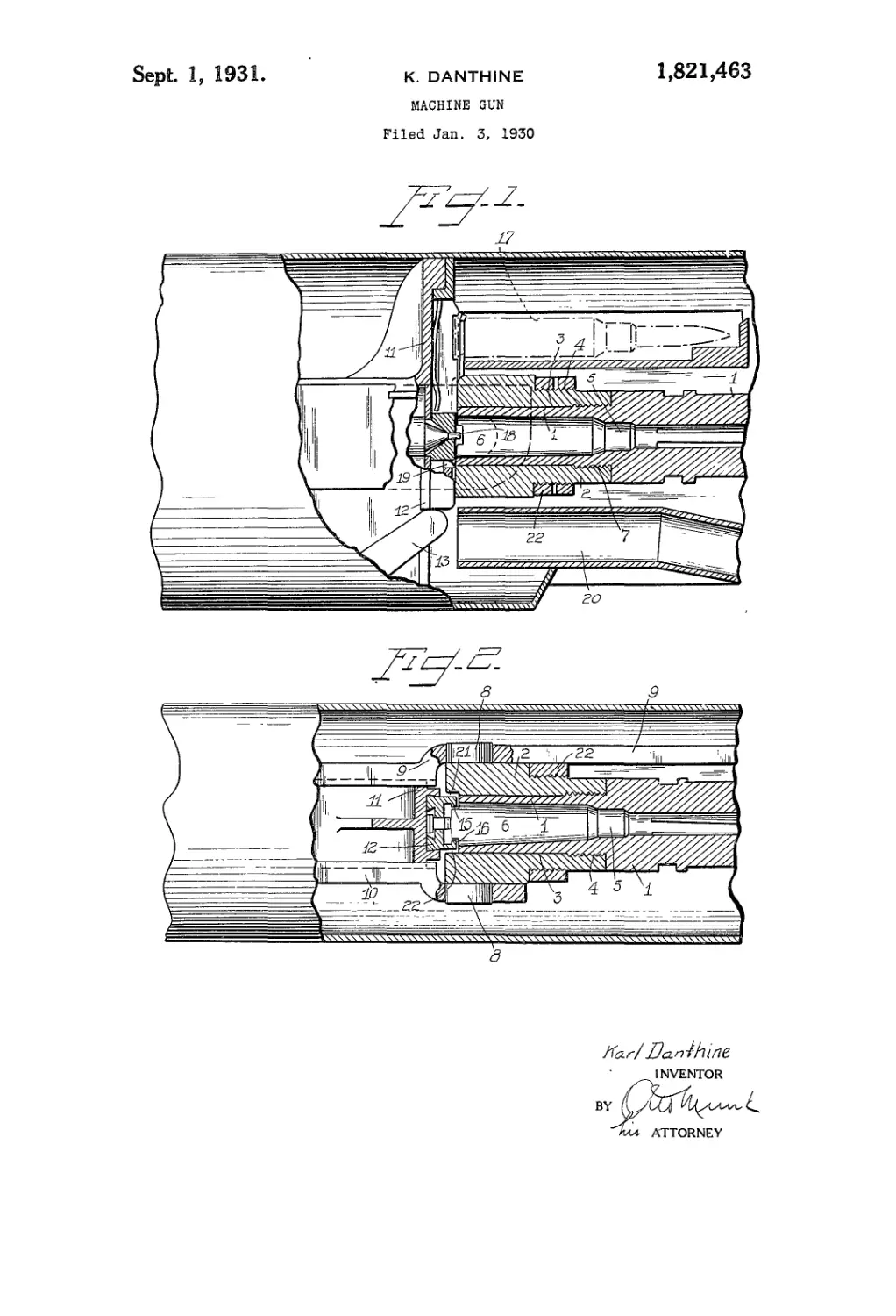
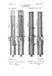
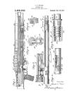
Fig. 1 shows an elevation partly in sec-
tion of a portion of a Maxim machine gun 65
provided with a barrel embodying the in-
vention.
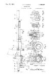
Fig. 2 is a top plan view of the same,
parts being shown in section.
In opposition to the usual construction of 70
the barrels of Maxim machine guns in which
the barrel is made in one piece with the back
portion or guide, in the new construction the
barrel consists of two separate parts. The
actual barrel 1 with the cartridge chamber 73
5, 6 made in one part is inserted into a
corresponding bore 3 of the back portion or
guide 2 and connected to it by means of a
thread 4 provided near the front end of the
cartridge chamber. In opposition to the 80
actual barrel 1 which as usually is of circular
cross section the back portion or guide 2 has
a rear part of essentially rectangular cross
section. 22 designates the usual ring
screwed on a threaded portion of the guide S1
2. The barrel 1 is secured against turning
in the thread 4 by means of a pin 7. The
back portion or guide 2 is provided in the
usual manner with two lateral projecting
cylindrical pins 8. These pins made in one
2
1,821,463
5
10
15
20
25
30
35
40
45
50
55
CO
piece with the portion 2 are mounted in
corresponding holes of two rails 9, 10, which
form parts of the reciprocating mechanism.
The lock 11 is arranged between the rails 9,
10 and guided thereon in horizontal direc-
tion. The usual slide 12 mounted on the
front of the lock is reciprocated in vertical
direction by means of the lever 13 mounted
to rock on an axle not shown in the drawings.
An upper spring pressed pawl 14 provided
on the slide 12 serves for seizing a cartridge
17 held as usually in a strip. The slide 12
is provided on its front with two lateral
claws 15, 16 serving to guide the cartridge
on the slide. 18 designates the striker pin
which in the position of the ignition shown
in Fig. 1 projects through a corresponding
opening of the slide 12. Near its lower end
of the slide 12 is provided with a lower
spring pressed pawl 19 serving to discharge
the cartridge case through the channel 20.
The back portion or guide 2 is provided with
two vertical recesses or grooves 21 into which
the claws 15, 16 of the slide 12 project when
the latter is moved in the position shown in
the drawings. The construction and opera-
tion of all these parts being known they are
not described in a detailed manner.
When the barrel 1 is worn out by shooting
and the cartridge chamber 5, 6 is worn out
by loading the barrel 1 with the back portion
or guide 2 can be detached from the rails 9.
10 in the usual manner. After removing the
pin 7 the barrel 1 with the cartridge cham-
ber 5, 6 can be unscrewed from the back
portion 2, and a new barrel with cartridge
chamber can be screwed into the back por-
tion 2. The back portion or guide 2 can be
used for an almost unlimited number of
spare barrels.
When barrels of the invention are used
with the same expenditure much more bar-
rels can be kept in reserve-as with the usual
construction of the barrels having the actual
barrel and the back portion made in one
piece.
Instead of being connected by means of a
thread the actual barrel 1 and the back por-
tion 2 could also be connected to another by
any other suitable means.
Instead of being formed cylindrically the
bore 3 of the back portion 2 and the corre-
sponding rear portion of the barrel 1 sur-
rounding the part 6 of the cartridge cham-
ber could also be formed conically.
I claim:
1. A machine gun, comprising a barrel, a
carrier for said barrel, and a barrel head
securing the barrel to said carrier, said bar-
rel comprising a barrel tube and cartridge
chamber detachably secured to said barrel
head, the latter being exchangeably attached
to said carrier and allowing either removal
of the barrel and the head, or the barrel
alone.
2. A machine gun comprising a barrel, a
carrier for said barrel, a barrel head to
support the barrel, and a pin to secure said
head to the carrier, said barrel comprising
a barrel tube and cartridge chamber screwed
in said barrel head, the latter being remov-
ably attached to said carrier by means of
said pin to either detach the barrel and the
head by removing said pin, or the barrel
alone by unscrewing the chamber. 75
3. A machine gun as claimed in claim 2,
including means to secure the barrel against
rotation in said barrel head.
4. In a machine gun of the class described,
the combination of a reciprocating media- go
nism, a barrel made in two pieces, the one
of said pieces comprising the actual barrel
and the cartridge chamber, the other one of
said pieces comprising the back portion of
the barrel, the rear end of the first piece ss
being inserted into said second piece and
exchangeably fastened thereto, and means
being made in one piece with said back por-
tion for interchangeably connecting it to the
reciprocating mechanism. oo
5. In a machine gun of the class described,
the combination of a reciprocating mecha-
nism comprising two rails, a barrel made
in two pieces, the one of said pieces compris-
ing the actual barrel and the cartridge chain- 95
ber, the other one of said pieces comprising
the back portion of the barrel, the rear encl
of said first piece being inserted into said
second piece and exchangeably fastened
thereto, and means being made in one piece ЮС
with said back portion for interchangeably
connecting it to said rails.
6. In a machine gun of the class described,
the combination of a reciprocating mecha-
nism comprising two rails, a hole provided ioc
in each rail, a barrel made in two pieces, the
one of said pieces comprising the actual
barrel and the cartridge chamber, the other
one of said pieces comprising the back por-
tion of the barrel, the rear end of said first nc
piece being inserted into said second piece
and exchangeably fastened thereto, and two
pins made in one piece with the back por-
tion and inserted in said holes of the rails.
7. In a machine gun of the class described, 115
the combination of a reciprocating mecha-
nism, a barrel made in two pieces, the one
of said pieces comprising the actual barrel
and the cartridge chamber, the other one of
said pieces comprising the back portion of 120
the barrel and being formed with a bore,
the rear end of said first piece being insert-
ed into the bore of said second piece and
screwed therein, and means being made in
one piece with said back portion for inter- 125
changeably connecting it to the reciprocat-
ing mechanism.
8. In a machine gun of the class described,
the combination of a reciprocating mecha-
nism, a barrel made in two pieces, the one of 130
G
10
IS
20
25
30
35
30
45
5(?
35
1,821,463 3
said pieces being of circular cross section
and comprising the actual barrel and the
cartridge chamber, the other one of said
pieces comprising the back portion of the
barrel, said back portion of the barrel being
formed with a bore and having a part of
rectangular cross section, the rear end of
said first piece being inserted into the bore
of said second piece and screwed therein,
and means being made in one piece with
said back portion for interchangeably con-
necting it to the reciprocating mechanism.
In testimony whereof I have signed my
name to this specification.
KARL DANTHINE.
GO