/
Tags: weapons military affairs patent
Year: 1939
Text
Sept. 5, 1939.
2,172,036
H. SCHMEISSER
AIK KIFLE
, Filed May 21, 1936
2 Sheets-Sheet 1
Sept. 5, 1939.
H. SCHMEISSER
AIR RIFLE
Filed May 21, 1936
2,172,036
2 Sheets-Sheet 2
Patented Sept. 5, 1939
2,172,036
UNITED STATES PATENT OFFICE
2,172,038
Allb BU'jlJS
Hurt» Schmeisser, Suhl, Thuringen, Germany
Application May 21, 1930, Serial No. 81,098
In Germany May 21, 1935
0 Claims. (Cl. 124—15)
This invention relates to an air rifle which
is similar in form and manipulation to a military
rifle and is set by means of a lever, and it has for
its primary object considerably to increase the
* force of the rifle, or in other words the force
of the compression spring, without at the same
time increasing the force necessary for setting
the said lever. An additional object of the in-
vention is to simplify the cocking or setting mech-
10 anism as regards the number and embodiment
of the parts.
According to the invention the compression
spring is cocked by the lever in two stages ap-
plied first in one direction to one end of the
1* spring and then in the opposite direction to the
other end of the spring. ,
The compression spring may comprise two
separate parts whereby the advantage is obtained
of setting these parts of the spring one after
SO the other by the backward and forward move-
ment of the lever. In this case the one com-
pression spring, the outer one, is preferably
mounted in a compression sleeve and guided over
the air plunger shaft, whilst the second com-
25 pression spring, the inner one, is mounted and
guided in a bore in the said shaft.
According to the invention, the inner compres-
sion spring, with the aid of an interposed pres-
sure member likewise provided in the plunger
80 shaft, is compressed in direct fashion by the
movement of the lever out of its rear into the
forward position, whilst the outer compression
spring is compressed .upon backward movement
of the plunger by means of the lever whereby
36 the spring is compressed between the plunger and
an abutment provided in a compression sleeve.
An additional feature of the invention resides
in the action of the said lever and the effect of
the setting or cocking operation on the charging
40 device of the rifle, a rod connected with the lever
acting in such fashion on a rotatable ammuni-
tion feed plug provided in the barrel of the rifle
that upon withdrawal of the lever the plug is
opened and upon the forward movement of the
46 lever the plug is closed.
Additional'features of the invention relate to
several different safety means; thus for example
to a means for preventing withdrawal of the
50 lever when the rifle is cocked and to a means
for preventing movement of the handle of the
lever except when the latter is situated in its
front initial or final position.
The invention will be described more fully
55 with reference to the accompanying drawings.
which illustrate two possible forms of embodi-
ment.
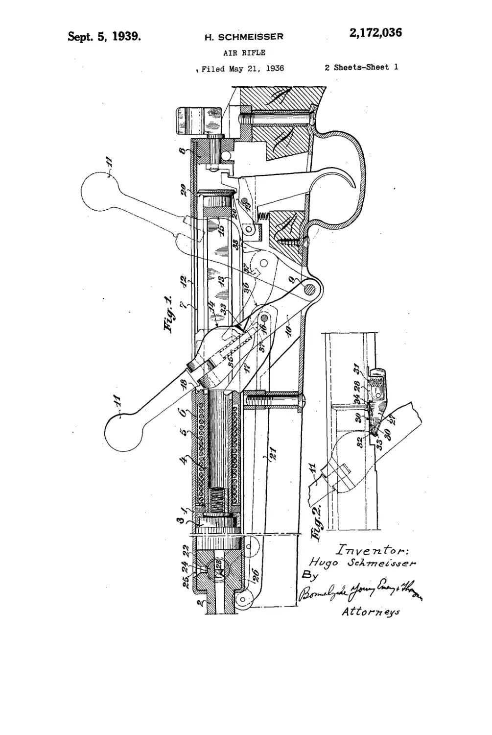
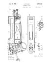
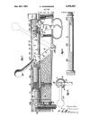
Fig. 1 is a vertical section through those parts
of the air rifle to which the invention relates,
the rifle being shown in the cocked or set posi- 5
tion with the position of the setting means after-
the preliminary setting operation indicated in
broken lines.
Fig. 2 shows the means for preventing back-
ward movement of the lever when the rifle has Ю
already been cocked or set.
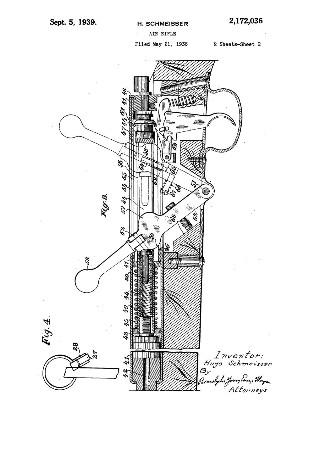
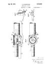
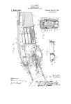
Fig. 3 is a view similar to Fig. 1 of a modified
form of embodiment of the invention.
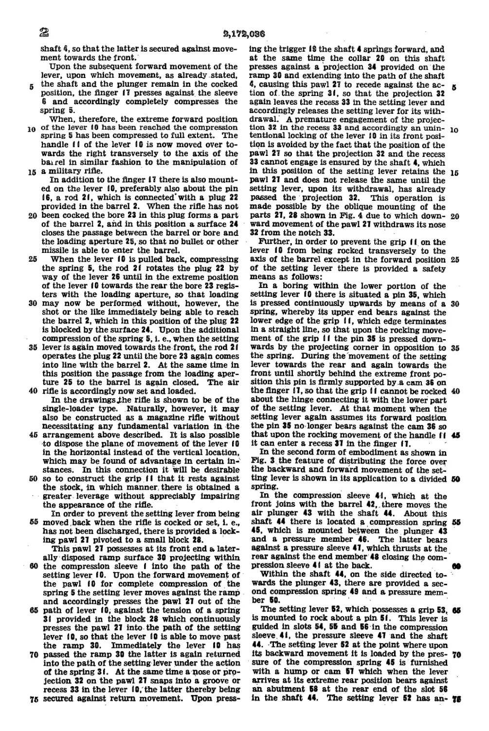
Fig. 4 is an end view of the means shown in
Fig. 2. 36
In the compression sleeve I, which at the front
is attached to the barrel 2, there moves the air
plunger 3 with the1 shaft 4. About this shaft 4
there is located the compression spring 5, which
in the relaxed condition is mounted partially, 20
viz., at the end opposite to the air plunger, in
a sleeve 6, which in turn is slidable in the com-
pression sleeve I this sliding being bounded to-
wards the rear by a pressure sleeve 1 which bears
against the end member 8 closing the compres- 25
sion sleeve at the back.
The setting lever 10, which possesses a grip
i i, is mounted to rock about a pin 9. This lever
is guided in slots 12 and 13 in the compression
sleeve I and the shaft 4. The lever 10 has a 30
hump or cam 14 on its rear face which upon
backward movement of the lever bears against
an abutment 15 at the rear end of the slot i3 .
in the shaft 4.
There is mounted on a pin 16 provided on the 35
lever iO a thrust finger II, the front end of
which bears continuously against the outer rear
face 18 of the sleeve 6 adapted to accommodate
the compression spring 5. In order to prevent
the finger II and the surface 18 from moving 40
out of contact with one another the correspond-
ing contacting portions, as illustrated by way of
example, may be curved.
If the lever 10 is pulled back by hand, the same,
owing to the fact that its cam 14 bears against 4
the abutment 15 of the shaft 4, also moves back
the said shaft and together therewith the plunger
3, resulting in compression of the spring 5 in its
sleeve 6, until the face 18 of this sleeve moves
against the pressure sleeve 1 (which is furnished
with a slot corresponding with the slots 12 and
13), this being equivalent to the shaft 4 reach-
ing its rearmost position. In this position the
trigger member 19 engages a collar 20 on the 55
М?й>оз®
shaft so that the latter Is secured against move-
ment towards the front.
Upon the subsequent forward movement of the
lever, upon which movement, as already stated,
g the shaft and the plunger remain in the cocked
position, the finger П presses against the sleeve
6 and accordingly completely compresses the
spring 5.
When, therefore, the extreme forward position
10 of the lever 10 has been reached the compression
spring 5 has been compressed to full extent. The
handle I i of the lever i 0 is now moved over to-
wards the right transversely to the axis of the
bairel in similar fashion to the manipulation of
15 a military rifle.
In addition to the finger 17 there is also mount-
ed on the lever iO, preferably also about the pin
86, a rod 21, which is connected* with a plug 22
provided in the barrel 2. When the rifle has not
20 been cocked the bore 23 in this plug forms a part
of the barrel 2, and in this position a surface 24
closes the passage between the barrel or bore and
the loading aperture 25, so that no bullet or other
missile is able to enter the barrel.
25 When the lever 10 is pulled back, compressing
the spring 5, the rod 21 rotates the plug 22 by
way of the lever 26 until in the extreme position
of the lever 10 towards the rear the bore 23 regis-
ters with the loading aperture, so that loading
30 may now be performed without, however, the
shot or the like immediately being able to reach
the barrel 2, which in this position of the plug 22
is blocked by the surface 24. Upon the additional
compression of the spring 5, i. e., when the setting
35 lever is again moved towards the front, the rod 21
operates the plug 22 until the bore 23 agajn comes
into line with the barrel 2. At the same time in
this position the passage from the loading aper-
ture 25 to the barrel is again closed. The air
40 rifle is accordingly now set and loaded.
In the drawings j;he rifle is shown to be of the
single-loader type. Naturally, however, it may
also be constructed as a magazine rifle without
necessitating any fundamental variation in the
45 arrangement above described. It is also possible
to dispose the plane of movement of the lever (0
in the horizontal instead of the vertical location,
which may be found of advantage in certain in-
stances. In this connection it will be desirable
50 so to construct the grip 11 that it rests against
the stock, in which manner, there is obtained a
greater leverage without appreciably impairing
the appearance of the rifle.
In order to prevent the setting lever from being
55 moved ,back when the rifle is cocked or set, i. e.,
has not been discharged, there is provided a lock-
ing pawl 27 pivoted to a small block 28.
This pawl 27 possesses at its front end a later-
ally disposed ramp surface 30 projecting within
60 the compression sleeve I into the path of the
setting lever *0- Upon the forward movement of
the pawl 10 for complete compression of the
spring 5 the setting lever moves against the ramp
and accordingly presses the pawl 27 out of the
65 path of lever 10, against the tension of a spring
38 provided in the block 28 which continuously
presses the pawl 21 into the path of the setting
lever 8 0, so that the lever 8 0 is able to move past
the ramp 30. Immediately the lever 10 has
70 passed the ramp 30 the latter is again returned
into the path of the setting lever under the action
of the spring 31. At the same time a pose or pro-
jection 32 on the pawl 27 snaps into a groove or
recess 33 in the lever 80,'the latter thereby being
75 secured against return movement. Upon press-
ing the trigger 19 the shaft 4 springs forward, and
at the same time the collar 20 on this shaft
presses against a projection 34 provided on the
ramp 30 and extending into the path of the shaft
4, causing this pawl 27 to recede against the ac- 5
tion of the spring 31, so that the projection 32
again leaves the recess 33 in the setting lever and
accordingly releases the setting lever for its with-
drawal. A premature engagement of the projec-
tion 32 in the recess 33 and accordingly an unin- ю
tentional locking of the lever 10 in its front posi-
tion is avoided by the fact that the position of the
pawl 27 so that the projection 32 and the recess
33 cannot engage is ensured by the shaft 4, which
in this position of the setting lever retains the 15
pawl 27 and does not release the same until the
setting lever, upon its withdrawal, has already
passed the projection 32. This operation is
made possible by the oblique mounting of the
parts 27, 28 shown in Fig. 4 due to which down- 20
ward movement of the pawl 27 withdraws its nose
32 from the notch 33.
Further, in order to prevent the grip 11 on the
lever 10 from being rocked transversely to the
axis of the barrel except in the forward position 25
of the setting lever there is provided a safety
means as follows:
In a boring within the lower portion of the
setting lever 10 there is situated a pin 35, which
is pressed continuously upwards by means of a 30
spring, whereby its upper end bears against the
lower edge of the grip 81, which edge terminates
in a straight line, so that upon the rocking move-
ment of the grip 81 the pin 35 is pressed down-
wards by the projecting corner in opposition to 35
the spring. During the'movement of the setting
lever towards the rear and again towards the
front until shortly behind the extreme front po-
sition this pin is firmly supported by a cam 36 on
the Anger 87, so that the grip 8 8 cannot be rocked 40
about the hinge connecting it with the lower part
of the setting lever. At that moment when the
setting lever again assumes its forward position
the pin 35 no longer bears against the cam 36 so
that upon the rocking movement of the handle I I 45
it can enter a recess 37 in the finger II.
In the second form of embodiment as shown in
Fig. 3 the feature of distributing the force over
the backward and forward movement of the set-
ting lever is shown in its application to a divided 50
spring.
In the compression sleeve 48, which at the
front joins with the barrel 42,. there moves the
air plunger 43 with the shaft 44. About this
shaft 44 there is located a compression spring 55
45, which is mounted between the plunger 43
and a pressure member 46. The latter bears
against a pressure sleeve 47, which thrusts at the
rear against the end member 48 closing the com-
pression sleeve 4 8 at the back. 80
Within the shaft 44, on the side directed to-
wards the plunger 43, there are provided a sec-
ond compression spring 49 and a pressure mem-
ber 50.
The setting lever 52, which possesses a grip 53, 85
is mounted to rock about a pin 51. This lever is
guided in slots 54, 55 and 56 in the compression
sleeve. 41, the pressure sleeve 47 and the shaft
44. The setting lever 52 at the point where upon
its backward movement it is loaded by the pres- 70
sure of the compression spring 45 is furnished
with a hump or cam 57 which when the lever
arrives at its extreme rear position bears against
an abutment 58 at the rear end of the slot 56
in the shaft 44. The setting lever 52 has an- 20
9,172,086
other hump or cam *1 on its front face, which
gears against the pressure member 50 within.the
shaft of the plunger.
If the lever 52 is pulled back by hand, the
g same, owing to the fact that its cam 57 bears
against the abutment 50 of the shaft 44, also
moves back the said shaft and together therewith
the plunger 43, the outer compression spring 45
thereby being compressed, i. e., cocked, between
the plunger 43 and the pressure disk 46. In this
way the spring is always compressed and relaxed
in the same direction. When the setting lever 52
has reached its rear position shown in the draw-
ings in broken lines, the spring 45 has been fully
25 compressed. In this position the trigger member
60 rests on the collar 01 of the shaft 44, so that
the latter and the plunger 43 are secured against
movement towards the front.
Upon the subsequent forward movement of
2Q the lever 52, upon which movement, as already
stated, the shaft 44 and the plunger 43 remain
in the cocked position, the cam 50 of the setting
lever 52 presses against the pressure member 60,
the inner compression spring 49 situated in the
25 shaft 44 thereby being compressed, i. e., set. In
this way the spring 49 also is always compressed
and relaxed in the same direction.
After the extreme front position of the lever 52
has been reached the grip 53 is also rocked to-
30 wards the right transversely to the axis of the
barrel, for which purpose the lever 52 and the
grip 53 are connected by a hinge 62.
In order, in the second form of embodiment,
likewise to prevent the grip 53 of the lever 52
35 from being rocked transversely to the axis of the
barrel except in the forward position of the lever
the safety means is preferably constructed as
follows:
Within a boring in the setting lever 58 there
40 is provided a pin 63 which is pressed continuously
upwards under the action of the spring 64, the
same bearing against the straight lower face of
the grip 53. Below the pin 63 there is provided
a bolt 67, which is shiftable in the transverse
45 direction and in the normal position supports
the pin 63 by means of an abutment 65. When
the setting lever 52 is located in its extreme for-
ward position the bolt 67 bears against a sur-
face 68 on the gun stock and is pressed back in
50 opposition to the spring 66. In this way there
is formed a space available for the longitudinal
displacement of the pin 63 downwards and into
which the pin 63 is able to enter upon the rocking
of the grip 53 by reason of the projecting corner
55 at its lower edge.
In every other position of the grip, i. e., upon
the backward and forward movement, the pin 63
is supported by the surface 65 again drawn in-
wards, so that the grip 53 is locked against lateral
60 rocking movement.
What I claim as new and desire to secure by
Letters Patent is:
1. In an air rifle, a compression spring adapted
to produce the force of discharge, a lever for com-
65 pressing the said spring in two successive move-
ments towards the rear and towards the front,
a handle hinged to said lever capable of turning
laterally thereto and means for preventing turn-
ing of the said handle on the lever except in the
70 extreme forward position of the lever, the said
means comprising a pin adapted to slide within
the said lever upon turning of the handle, a cam
supporting the said pin, and a recess in the said
cam situated below the pin in the extreme forward
75 position of the lever.
3
2. In an air rifle, a compression spring adapted
to produce the force of discharge, a lever for
compressing the said spring in two successive
movements towards the rear and towards the
front, a handle hinged to said lever capable of g
turning laterally thereto and means for prevent-
ing turning of the handle except in the extreme
forward position of the lever, the said means
comprising a pin adapted to slide within the said
lever when the handle is turned, a spring acting 20
on the said pin, and a spring-controlled bolt act-
ing as a support for the said pin.
.3. In an air rifle, a compression sleeve, an air
plunger in said sleeve, a shaft extending rear-
wardly of the plunger, compression spring means 25
for operating the plunger in said sleeve, a lever
for cocking the spring means said lever being
pivotal rearwardly and forwardly about an axis
outside said sleeve and guided in slots in the sleeve
and shaft, means whereby the spring means is 20
cocked partly by rearward movement and partly
by forward movement of said lever, the said two
cocking operations being effected upon opposite
ends of said spring means, an intermediate hinge
in the cocking lever enabling its outermost part 25
forming a handle to be turned with respect to
the inner part transversely to the direction of
pivoting of the lever, and means for preventing
such turning of the handle except when the lever
is in forward position. 30
4. In an air rifle, a compression sleeve, an air
plunger in said sleeve, a shaft extending rear-
wardly of the plunger, compression spring means
for operating the plunger, a sleeve slidable in the
compression sleeve and fully containing said 35
spring means when cocked and partly containing
said spring means when uncocked, a lever for
cocking the spring means, said lever being pivot-
able rearwardly and forwardly about an axis out-
side said sleeve and guided in slots in the sleeve 40
and shaft, an abutment on the plunger shaft
whereby the spring means is cocked partly by
rearward movement of the lever, a thrust Anger
carried by the cocking lever and bearing against
the spring means containing sleeve in the for- 45
ward movement of the cocking lever to complete
the cocking of said spring means, the said two
cocking operations being effected upon opposite
ends of said spring means, an intermediate hinge
in the cocking lever enabling its outermost part 50
forming a handle to be turned with respect to the
inner part transversely to the direction of pivot-
ing of the lever, and means for preventing such
turning of the handle except, when the lever is
in forward position, said preventing means in- 55
eluding a spring operated sliding member in the
cocking lever cooperating with a cam surface on
the thrust finger.
5. In an air rifle, an air plunger and shaft,
spring means operating on said plunger to pro- 60
duce the force of discharge, a lever for compres-
sing the said spring means in two successive
movements towards the rear and towards the
front, and means for preventing rearward move-
ment of said lever when the spring means is 65
compressed, said means including a spring pressed
pawl extending obliquely into the path of the
lever and arranged to yield to allow the lever
to pass the pawl in its forward movement but
then to engage and hold the lever in its forward 70
position, said pawl having a ramp surface co-
operating with the plunger shaft when the rifle is
fired to disengage the pawl from the lever.
6. In an air rifle, a compression sleeve, an air
plunger in said sleeve, a shaft extending rear- 75
<
wardly of the plunger, compression spring means
for operating the plunger in said sleeve, a lever
for cocking the spring means said lever being
pivotable rearwardly and forwardly about an axis
g below said sleeve and extending upwardly through
and guided in slots in the sleeve and shaft, means
whereby the spring means is cocked in two sub-
stantial stages by successive rearward and for-
ward movements of said lever, the said two cock-
ing operations being applied first to one end only
and then to the other end only of said spring
means, means automatically put out of action on
firing the rifle for preventing rearward movement
@,ате,от®'
of the cocking lever when the second cocking
operation is completed, said preventing means
including a pawl mounted out of the path of
travel of the cocking lever but with its nose mov-
able into and out of said path, the lever having 5
a notch engaging said nose to lock the lever in
forward position when the spring means is cocked,
and the pawl having a ramp surface cooperating
with a projection on the plunger shaft to disen-
gage the nose from the notch at the end of the 10
forward movement of the shaft when the rifle is
fired.
HUGO SCHMEISSER.