/
Tags: weapons military affairs patent
Year: 1937

Text
Jan. 26, 1937.
H. SCHMEISSER
AIR GUN
2,068,823
Jan. 26, 1937.
2,068,823
H. SCHMEISSER
AIR GUN
Filed Jan. 31, 1934 2 Sheets-Sheet 2
Patented Jan. 26, 1937
2,068,823
UNITED STATES PATENT OFFICE
2,068,823
AIR GUN
Hugo Schmeisser, Suhl, Thuringia, Germany
Application January 31, 1934, Serial No. 709,178
In Germany February 7,1933
6 Claims. (Cl. 124—10)
For the purpose of practice in handling and
shooting with military rifles, air guns are made
which are charged by means of a so-called
Mauser lock. This Mauser lock consists of a
5 cylindrical compressing piece on which, in a
similar manner to military rifles, the breech bolt
is placed.
In order to charge the air gun, the breech bolt
. is pushed forward in a slot of the compression
10 chamber sleeve, and by means of a curved com-
pression piece on the compression sleeve the
greatest opposing end thrust of the compression
spring is overcome.
The air guns just described have the great dis-
15 advantage that the compressing of the compres-
sion spring, in spite of the curved charging piece,
is still far too hard to operate, so that the pene-
trating power of the weapon must be reduced.
The removal of this disadvantage, that is, en-
2o abling the gun to be charged as easily as pos-
sible with increasing load, while at the same time
keeping the operation similar to that of the mili-
tary rifle, is achieved essentially (making use of
the principle of lever charging) by arranging
25 that the compressing lever is operated in the di-
rection of the barrel axis and that that part
' of it which protrudes from the gun is arranged
to swing transversely to the barrel axis in a sim-
ilar way to the breech bolt of military rifles. The
30 handle is then connected with the compressing
lever by means of a link which allows it to swing
in a transverse direction. The compression
chamber, as well as the chamber for receiving
the compression spring, and also the chamber
35 for receiving the rod of the air piston when in the
charged position, preferably lie between the
centre of rotation of the compressing lever and
the point where the force of this is applied. The
compression spring passes through the chamber
40 carrying the compression spring, which chamber
in its continuation constitutes, at the same time,
the compression chamber, or connects up to such
a chamber.
In order to make the air gun more similar to
45 the military rifle in its handling and’ shooting,
according to a further object of the invention it
may also be formed as a repeating rifle and pro-
vided with a magazine. According to the inven-
tion the shots lie in the magazine one above the
50 other, and are led successively to the barrel by
means of a spring and feeder. The magazine
is formed in such a way that as long as it is
outside the weapon the uppermost shot is held
by a stop arranged on the magazine, which is
55 automatically thrown out when the magazine is
placed in the gun, whereby the shots can freely
enter the barrel one after the other. The stop
consists preferably of a slide actuated by a spring,
and which normally projects through an inclined
guide into the shot pocket and over the upper 5
edge of the magazine, while when the magazine
is inserted, the slide is guided into the releasing
position by the slide striking against the interior
of the gun.
By means of the arrangement and construction 10
of the magazine in accordance with the inven-
tion, the disadvantages existing with the known
repeating air guns are avoided, these consisting
in that the feeding device, when filled with a
large number of shots, can only be emptied again 15
with great difficulty and trouble and, in view
thereof, the complete discharging of the gun
after shooting is often neglected, and it then rep-
resents a certain danger in unskilled hands.
In addition, the complete absence of shots in a 20
gun can not be definitely determined in known
shot-feeding devices. Beside the avoidance of
these disadvantages, the magazine or the shot-
feeding device in the gun according to the inven-
tion, has the advantage of being simple and of 25
functioning with certainty.
A constructional example of the gun accord-
ing to the invention is shown in the drawings.
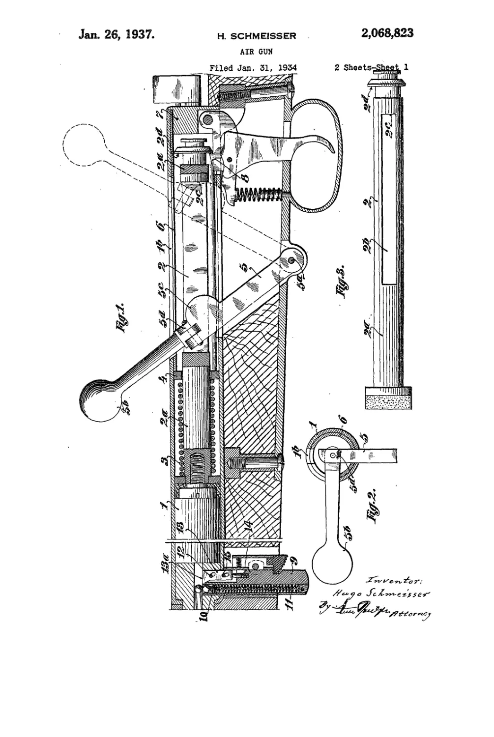
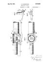
Figure 1 shows the most Important middle part
of the air gun with .magazine, in a vertical longl- 30
tudinal section, with the air piston in the charged
condition and the compressing lever moved for-
ward again. The backward position of the com-
pressing lever in the compressing position is
shown dotted. 35
Figure 2 is a cross sectional view of the middle
part of the air gun showing the compressing lever
handle swung round about the axis of the barrel.
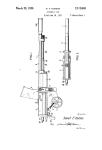
Figure 3 is a plan view of the air piston.
The air piston 2 moves in the compression cyl- 40
inder I which is connected at the front end with
the barrel. The compression spring 3, which
bears against a pressure disc 4 at the rear, is
mounted over the rod 2a of the air piston 2. In
the rod 2a of the air piston, and in an extension 45
of the cylinder are slots 2b and lb, in which moves
the compressing lever 5, whose centre of rotation
5a is, in the example shown in the drawings,
underneath the extension. At the end of the
piston rod 2a is the compression catch 2d, with 50
which the trigger 8 engages in the charged posi-
tion in a known manner. The compressing lever
5 has an extension formed as a breech bolt, and
carries a knob 5b at the place where it is held,
this in the present case being made spherical or 55
3)063)333
pear-shaped as In the case of a breech bolt. At
the point where the compressing lever takes the
pressure of the compression spring, It Is provided
with a curved hump 5c. This curved hump bears
5 against the surface 2c in the slot 2b of the air
piston. The pressure disc 4 is supported against
the abutment sleeve 6 which in turn is provided
with slots for the movement of the operating
handle like the compression cylinder I and is
10 supported at the rear against a base 1, closing the
cylinder. That part of the operating lever form-
ing the breech bolt is made rotatable about a
Joint 5d, so that the handle 5b, when moved into
the forward position of the operating lever, can
15 be swung to the right, transversely to the barrel
axis, through about 90°.
When the operating lever 5 is drawn back by
hand, it carries the piston 2 back with it, owing
to its bearing on the surface 2c, and thereby com-
20 presses the compression spring 3, this meanwhile
being supported against the abutment sleeve 6,
through the intermediary of the pressure disc
4. At the end of the movement of the piston 2,
the trigger 8 engages in the compression catch
25 2d. of the piston 2. The operating lever 5 is again
moved forward, without load, and in its end posi-
tion the handle is swung to the right about the
axis of the barrel. The air gun is now charged
and loaded.
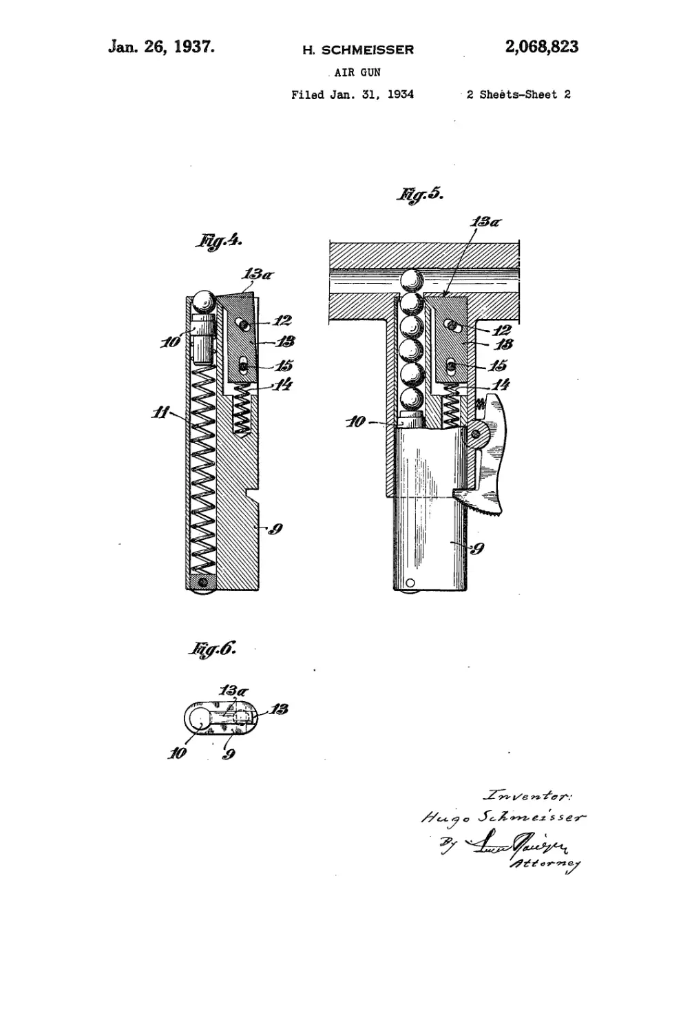
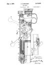
30 The magazine 9 is mounted in the stock of the
gun at the rear end of the barrel (Figure 1). In
this is a vertical pocket, whose cross section is
adapted exactly to the actual shot used. The
shot lie one above the other in this pocket, and
35 are raised towards the pocket opening by the
feeder 10, which is acted on by the pressure of
the feeder spring II. At the side of this pocket
is arranged the lever-like stop 13, which can
swing about a pin 12. The spring 14 causes the
40 upper lever arm of the stop to tip over into the
opening of the pocket, whereby the exit of the
uppermost shot from the magazine is prevented.
The lower pin 15 limits the small longitudinal
movement which the stop 13 executes in addition
45 to the lever movement.
In the blocked condition the upper lever arm
of the stop protrudes with a surface 13a above
the upper edge of the magazine casing 9. If the
magazine is now inserted in the air gun or air
50 pistol, the projecting surface 13a comes to bear
against the inside of the gun, whereby the upper
lever arm of the stop is moved away from the
pocket and the uppermost bullet and those follow-
ing can rise up successively into the barrel.! The
55 magazine can, of course, be used also with air
pistols. ..
Having now particularly described and ascer-
tained the nature of my said invention and in
what manner the same is to be performed, I de-
60 Clare that what I claim is:—
1. Air gun with shot feeding device comprising
a housing containing a compression cylinder
communicating with the barrel of the gun, an air
piston in said cylinder, a piston rod, a compres-
65 sion spring for actuating the piston, a lever oper-
able in the plane of the barrel axis for loading the
said spring, and an abutment sleeve in said hous-
ing rearwardly of the piston between which latter
and the sleeve the spring is mounted, said cyl-
70 inder, abutment sleeve and piston rod having
complementary slots for guiding the lever.
2. An air gun with shot feeding device com-
prising a barrel, a housing containing a compres-
sion cylinder communicating with the barrel, an
air piston in the compression cylinder, a piston
rod, a compression spring for actuating the pis- 5
ton, a lever for cocking the compression spring,
said lever being pivoted in the gun about an axis
below the housing and guided by slots in the hous-
ing and the piston rod, a curved hump on said
lever engaging the rear end of the slot in the 10
piston rod when the spring is being cocked, and
a handle on said lever which handle can be
turned transversely, to the barrel axis.
3. An air gun with shot feeding device com-
prising a barrel, a housing containing a com- 15
pression cylinder communicating with the barrel,
an air piston in the compression cylinder, a pis-
ton rod, a compression spring for actuating the
piston, a lever for cocking the compression spring,
said lever being pivoted in the gun about an axis 20
below the housing and guided by slots in the
housing and the piston rod, a curved hump on
said lever engaging the rear end of the slot in the
piston rod in the line of action of the compression
spring when said spring is being cocked, and a 25
handle on said lever which handle can be turned
transversely to the barrel axis.
4. An air gun with shot feeding device compris-
ing a barrel, a housing containing a compression
cylinder communicating with the barrel, an air 30
piston in the compression cylinder, a piston rod,
a compression spring for actuating the piston, a
lever for cocking the compression spring, said le-
ver being pivoted in the gun about an axis below
the housing and guided by slots in the housing
and the piston rod, a curved hump on said lever
engaging the rear end of the slot in the piston
rod in the line of action of the compression spring
when said spring is being cocked, and a handle on
said lever which handle can be turned trans- 4C
versely to the barrel axis, the location of the le-
ver axis below the housing being intermediate
of the ends of the slot in the piston rod when the
spring is cocked.
5. An air gun with shot feeding device com- 4.’
prising a barrel, a housing containing a com-
pression cylinder communicating with the bar-
rel, an air piston in the compression cylinder, a
piston rod, a compression spring for actuating
the piston, a lever for cocking the compression 5(
spring, said lever being pivoted in the gun about
an axis near the bottom of the housing and a
handle connected by a hinge to said lever and
projecting through the top of the housing, said
handle being movable on the hinge transversely 51
to the barrel axis.
6. An air gun with shot feeding device com-
prising a barrel, a housing containing a com-
pression cylinder communicating with the barrel,
an air piston in the compression cylinder, a pis- 6t
ton rod, a compression spring for actuating the
piston, a lever for cocking the compression spring
said lever being pivoted in the gun about an
axis near the bottom of the housing, and a handle
connected by a hinge to said lever and projecting 6;
through the top of the housing, said handle being
movable" on the hinge transversely to the barrel
axis and the axis of the hinge being substantially
at right angles to the longitudinal axis of said
lever and said handle. 7(
HUGO SCHMEISSER.