/


Tags: weapons military affairs patent
Year: 1939

Text
Jan. 17, 1939
Н O. E1ANE
2,144,241
AUTOMATIC RIFLE
Filed June 1, 1936
4 Sheets-Sheet 1
Jan. 17, 1939.
Н O. EIANE
AUTOMATIC RIFLE
Filed June 1, 1936
2,144,241
4 Sheets-Sheet 2
Jan. 17, 1939
Н O. EIANE
2,144,241
AUTOMATIC RIFLE
Filed June 1, 1936
4 Sheets-Sheet 3
Jan. 17, 1939
Н O EIANE
2,144,241
AUTOMATIC RIFLE
Filed June 1, 1933
4 Sheets-Sheet 4
Patented Jan. 17, 1939
2,144,241
UNITED STATES PATENT OFFICE
2,144,241
AUTOMATIC RIFLE
Halvor Olsen Eiane, Washington Island, Wis.
Application June 1, 1936, Serial No. 82,811
5
10
15
20
30
35
40
45
50
55
17 Claims.
My invention relates to improvements in auto-
matic fire-arms in which the breech bolt is locked
by turning its lugs into recessed seat in the re-
ceiver and operated by the force of powder gas
from the bore of the rifle; and the objects of
my improvements are: First, to utilize the well
known and reliable bolt action principle in con-
junction with automatic operation; second, to
provide means for quick and easy dismounting
of the breech bolt mechanism for cleaning and
inspection of the bore from the breech end of
the barrel; third, to provide a fire-arm with
straight striking firing pin, in order to attain the
best accuracy in firing; fourth, to provide the
fire-arm with automatic warning signal when
the magazine is empty, by having the raised bolt
handle obscure the line of sight; fifth, to utilize
stored gas from a reservoir on the expansion
principle as automatic motive power instead of
operating the automatic mechanism on the im-
pulse principle.
I attain these objects by the use of an auto-
matic gun mechanism hereinafter more fully de-
scribed and claimed having reference to the ac-
companying drawings, in which Fig. 1 is a frag-
mentary view in elevation partly in section of
the receiver with the bolt mechanism in locked
position.
Fig, 2 is a bottom plan view of the receiver,
showing the magazine throat and sear box in
position.
Fig. 3 is a bottom plan view of the sear spring.
Fig. 4 is a side view of the complete sear mech-
anism.
Fig. 5 is a top plan view of the receiver with
the breech bolt in locked position, showing the
crosshead sleeve detached from one of the op-
erating connecting rods.
Fig. 6 is a front end view of the receiver with
parts removed.
Fig. 7 is a rear end view of the receiver with
parts removed.
Fig. 8 is a rear view of a crosshead sleeve.
Fig. 9 is a right side view of the crosshead sleeve
partly in section.
Fig. 10 is a side view in elevation of the cross-
head sleeve, showing the opposite side of said
sleeve.
Fig. 11 is a bottom plan view of a crosshead
pin, showing locking plunger and spiral spring in
detached relation.
Fig. 12 is a longitudinal vertical section of the
gas cylinders and valve mechanism connected to
the rifle.
Fig. 13 is a fragmentary top plan view, partly
(Cl. 42—3)
in section, of the piston-rod and piston assembly.
Fig. 14 is an enlarged vertical section of the
check-valve and housing, shown in detached re-
lation.
Fig. 15 is a top plan view of a barbed split-key, 5
shown detached.
Fig. 16 is a cross section of the gas cylinder and
valve-rod.
Fig. 17 is a bottom plan view of a control valve,
showing in detached relation a collar and a nut. 10
Fig. 18 is a right side view of the firing pin
assembly partly in section and showing certain of
the elements detached.
Fig. 19 is a right side view of the bolt sleeve,
shown detached. 1#
Fig. 20 is a transverse vertical section taken at
the bolt handle of the breech bolt.
Fig. 21 is a bottom plan view of the breech
bolt, shown detached.
Fig. 22 is a longitudinal side view of the fire- 20
arm constructed in accordance with the prin-
ciples of my invention.
Fig. 23 is a top plan view of the magazine
follower.
Fig. 24 is a top plan view of the bolt stop and 25
associated members, shown in detached relations.
Fig. 25 is a top plan view of the ejector.
Fig. 26 is a rear end view of the piston.
Fig. 27 is a rear view of a locking sleeve.
Fig. 28 is a side view of the locking sleeve. 30
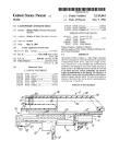
Referring more particularly to Figures 1, 2 and
5, it will be seen that the usual receiver A, a
breech bolt 2 and a bolt-operating handle or
lever 3 is provided in connection with a cartridge
extractor 4 and an extractor-band 5. 35
The bottom of the receiver is approximately
square when viewed from the front end although
the lower corners of the bottom are slightly
rounded so that the full strength of the material
is retained at points where longitudinal passages 40
6 are drilled throughout the entire length of the
receiver for slidably supporting connecting rods
8 and 9.
These passages are parallel to each other and
likewise parallel to the bore 7 in which the breech 45
bolt 2 operates.
The connecting rods 3 and 9 are particularly
constructed at their ends so that they may be
readily removed from their supports in a cross
head sleeve 12 at the rear end of the receiver A 50
and radial crosshead lugs 13 and IG located in
front of the receiver A.
The connecting rods 8 and 9 are secured within
threaded lugs 18 and II, respectively, formed on
the lower rear portion of the crosshead sleeve 12. 65
2,144,241
10
15
20
25
30
35
40
45
50
55
60
65
70
75
2
The connecting rod 8 is provided with right
hand threads at its rear end and left hand threads
at its front end for the purpose of obtaining
minute adjustment before being permanently
fixed to the lug 10 by means of solder or rivets.
The front end of the rod 8 is threaded into a
radial crosshead lug 13 formed on the rear end of
the piston-rod 14.
The connecting rod 9 on the other hand is
provided with left hand threads at its opposite
ends and these threads are milled away in quarter
sections, as shown at 15 (Figs. 5 and 13) at
diametiically opposite points. Likewise, the in-
ternally threaded passages in lugs 11 and 16 are
cut away to correspond with the milling of the
threads of the connecting rod 9 in such a man-
ner that when the mutilated threads on the ends
of the rod 9 align with the channels I5A in lug
• I (Fig. 8) the rod may be removed from its
bearings in the crosshead sleeve 12 and the cross-
head lug 16. The lug (6 is shown more particu-
larly in Fig. 13.
A thumb leaf П is secured to the rod 9 and
is adapted to rock the rod a quarter of a turn
for aligning the mutilated threads on the said rod
with the channels in the bearings or lugs I i
and 16.
When the thumb leaf 17 is located in an upright
locked position, the threads at both ends of the
rod 9 are engaged respectively with the threads
in their bearings, but a 90 degrees turn to the left
of the thumb leaf disengages the threads at both
ends and the rod can be moved forward to clear
the lug 11 in the crosshead sleeve 12.
The front end of the connecting rod 9 beyond
the lug 16 is squared to receive a collar 18 having
a complementarily formed square hole and a
nut 19 is threaded onto the forward end of the
rod for aiding in lining up the respective threads
of the rod and the lug.
The thumb leaf 17 is provided with a locking
recess 26 which has a semi-circular counterbored
seat into which a semi-circular collar 21 on the
end of a crosshead pin 22 turns for locking the
thumb leaf against accidental displacement (Figs.
10 and 11).
The crosshead pin 22 is mounted in the passage
24 in the crosshead sleeve 12 and is provided with
an approximately semi-circular collar 25 which
fits into a semi-circular recess 26 located in a
boss 27 formed on the right side of the cross-
head sleeve 12, thereby insuring the crosshead
pin against lateral end play as long as the collar
25 occupies the recess 26.
A lever 28 is connected with the crosshead pin
22 and is provided with a web portion for rein-
forcing the same.
A cylindrical sleeve 29 is formed adjacent the
free end of the lever 28 and provides a bearing
for a lock plunger 39 which is acted upon by a
spiral spring 31 for maintaining the free end of
the plunger projected from the sleeve 29. The
axis of said cylindrical sleeve is parallel to the
axis of the crosshead pin 22 and said sleeve is
located inwardly of the free end of the lever 28,
as shown more particularly in Fig. 11.
The plunger 39 has its inner end threaded into
a knurled button or head 33, after which said end
is riveted or secured in any approved manner to
prevent the same from working loose.
It will be noted that the button or head 33 is
nested within the flange or web of the lever 28
and this web serves as a guide for the member
33 and relieves the comparatively weak plunger
39 from hard knocks incidental to rough usage.
A locking sector 34 is located at the right side
of the crosshead sleeve 12 and is provided with
pockets 35, 36 and 37, as shown more particularly
in Figs. 1 and 9. These pockets are adapted to
receive the free and projecting end of the plunger 5
39 as the lever 28 is rocked for rocking the cross-
head pin 22, and these pockets in connection with
the plunger 38 will maintain the lever 28 and
likewise the pin 22 in a plurality of positions.
The pocket 35 in connection with the plunger ю
39 locks the lever 28 in “full safety position”, while
the pocket 36 locks the lever in "semi-safety posi-
tion”.
The pocket 37 will maintain the lever 28 and
likewise the pin 22 in “firing position.” 15
When it is desired to release the lever 28 from
one of its locked positions, it is only necessary to
withdraw the plunger 39 by means of the knurled
head 33. However, the pocket 36 is relatively
shallow so that when sufficient pressure is ap- 20
plied to the knurled head 33 the plunger 39 will
slide out of the pocket, whereby the lever 28 may
be rocked as desired.
The pockets 35 and 36 are located within the
confines of a tapered groove 38, so that when 25
the free end of the plunger 39 rides in this groove
the groove will guide the plunger toward the
pockets 35 and 36.
Referring more particularly to Figs. 20 and 21,
it will be seen that the breech bolt is provided 30
with two locking lugs 39 and 49 at diametrically
opposite points at the front end of the bolt and
a safety lug 41 is disposed adjacent the bolt
handle 3. The lug 49 is split to provide a nar-
row groove 42 (indicated by dotted lines in Fig. 35
20) to permit an ejector 43 (Figs. 7 and 25) to
reach the head of the cartridge to be extracted.
In other words, this groove is provided as a pas-
sage for the ejector 43.
The rear end of the breech bolt 2 is provided 40
with spiral cam slots 44 having notches 45 form-
ing neutral lock seats for the crosshead pin 22 as
will be presently explained.
The handle 3 is rigidly connected to the hollow
breech bolt 2 between the lug 41 and the slots 44. 45
The firing pin assembly (Fig. 18) is carried
within the hollow breech bolt 2 and includes a fir-
ing pin 46 provided with an arm 47 which is
spaced from the pin and has its upper edge paral-
lel to the axis of the pin. The forward end of 50
this arm is provided with a sear notch 48.
The firing pin per se is of comparatively large
diameter and has a transverse passage 49 which
serves as a safety lock notch for the firing pin
and approximately lines up with the crosshead 55
pin 22 when the latter is in its normal position
and the firing pin is in cocked position.
A straight slot 59 extends rearwardly from the
transverse passage 49 but has less width than
the diameter of the passage. go
This slot is adapted to receive the flat milled
section 72 of the crosshead pin 22, and this sec-
tion is adapted to move through the slot as will
be presently explained.
The length of the slot 56 plus the diameter of gg
the transverse passage 49 corresponds in length
to approximately three-quarters of the distance
the firing pin 46 is carried rearwardly by the
crosshead pin 22 while said pin moves rearwardly
through the spiral cam slots 44 (Figs. 5 and 21). -q
This movement of the firing pin is utilized for
striking purpose, while the remaining portion of
the rearward travel is utilized for storing up re-
serve power for assisting in the closing operation
of the breech bolt 2. 7-
2,144,241
5
10
15
20
25
30
35
40
45
50
GO
G5
70
75
The central portion of the firing pin assembly
is indicated at 51 and is of a smaller diameter
than the firing pin per se but forms an integral
portion of the firing pin 46. The front end of
the section 51 is made hexagonal, as shown at 52,
to fit into a complementarily formed passage in a
lock collar 53. Beyond the hexagonal portion 52,
the section 5t is threaded as shown at 57 and a
spiral spring 64 embraces the section 5i and abuts
the outer end of a square cut threaded section 62
formed on the sleeve 60.
The extreme front end of the firing pin as-
sembly includes a section 54 which carries a strik-
ing point 55 at the front end.
The rear end of the section 54 is enlarged at
56 and this section is bored and threaded on the
inside to receive the threaded end 57 of the
section 51. A tenon 58 on the enlarged portion
57 meshes with a mortise 59 on the collar 53. so
that these parts are locked together.
The firing pin 46 is centrally bored to reduce
the weight, and this bore extends from the rear
end to the slot 56.
The bolt sleeve 60 is received by the firing pin
46 and has a pair of diametrically disposed slots
6! through which the crosshead pin passes for
maintaining the sleeve from turning to the right
or left. The rear end of the sleeve is provided
with an extension 63 which is for the purpose of
aiding in turning the sleeve for screwing the same
in position.
In assembling the bolt mechanism, the firing
pin 46 is placed within the bolt sleeve 60 and the
spring 64 is placed over the front of the firing
pin in embracing relation with the section 51.
With the rear end of the spring abutting the
threaded portion 62. the lock collar 53 is placed
on the outer free end of the section 51 and is re-
ceived by the hexagonal portion 52 and is moved
inwardly of the section 51 and until it clears the
threaded end 57. The member 54 is then screwed
into place on the threaded end 57 of the section
51. When the tenon 58 aligns with the mortise
59 the parts are locked together and maintained
under pressure by the spring 64.
When the spring 64 is compressed between the
member 62 and the collar 53, the bolt sleeve 60
serves as a main spring shoulder for the inside
of the breech bolt 2 since the threads 62 on the
sleeve 69 are screwed into complementary
threads 65 (Fig. 20) in the breech bolt 2.
The securing of the firing pin assembly within
the breech bolt is accomplished by means of a
knurled head 66 on the firing pin 46, by turning
the head 66 to the right so that the arm 47 will
engage the rear extension 63 on the sleeve 60
whereby the sleeve can be turned in the desired
direction.
Since the intermeshing threads 62 and 65 fit
rather loosely no tools are required for screwing
the firing pin assembly into the breech bolt.
The receiver A, breech bolt 2, extractor 4 and
the cartridge magazine are well known in the art
and are of the type found in the German Mauser
rifle except those portions which are located at
the rear of the receiver bridge 67 and the front
ends of the lug races or grooves 68 which arc
provided with spiral faced cams 69 (Fig. 6).
A bolt stop 76 has a knurled head 7! and is
pivoted upon a screw-bolt 73 carried by the re-
ceiver A. The free end of this stop or lever is
provided with a projection or prong 77, which is
located within a slot formed in the left side of
the receiver A.
The lever is also provided with a lug or projec-
3
tion 75 which blocks the left lug race or groove
68 but does not normally contact with the left
locking lug 40 of the breech bolt 2 as the rearward
momentum of the said bolt is broken by a buffer
arrangement which will be presently described. 5
A pointed plunger 78 is adapted to engage a
double acting cam-notch 82 at the rear of the
lever 70 for retaining said lever in position. A
spring located in a passage 80 (Figs. 5 and 7)
maintains the plunger 78 in engagement with the ю
cam-notch 82, and a threaded plug 81 screwed
into the outer threaded end of the passage 80
maintains the spring in position.
The prong or projection 77 is split as indicated
by dotted lines, as shown at 83, to enable said 15
projection or prong to ride over the ejector 43.
Before inserting the breech bolt 2 into the bore
7 of the receiver A, the bolt stop or lever 70 is
first pulled out to the left by the knurled head 71
and the passage through which the breech bolt 20
moves is free so that the bolt may be pushed and
turned into its forward position.
The crosshead sleeve 12 is then moved up-
wardly and towards the left from the position
shown in Fig. 5 until the passage in the lug 11 25
lines up with the rear end of the connecting
rod 9.
This rod can then be pulled rearwardly by the
thumb leaf 17 until stopped by contact with the
lug 11. After this the thumb leaf is then raised 30
to its normal locked position on the left side of
the crosshead sleeve i2. The last act of assem-
bling includes the insertion of the crosshead pin
22 through the passage 24 from the right side
of the crosshead sleeve 12, then through the spiral 35
cam slot 44 and through the right side longi-
tudinal slot 61 in the bolt sleeve 60.
The firing pin 46 is then drawn up by its
knurled head 66 slightly beyond the full cocked
position to which point the transverse passage
49 aligns with the crosshead pin 22 and then said
pin can be moved into place.
During these operations, care must be exercised
so that the lever 28 is in a forward and upward
position before the final movement takes place
of the crosshead pin 22 so that the collars 2(
and 25 (Fig. 11) can pass into their respective
recesses 20 and 26 after which the turning leaf
or lever 28 is rocked to the rear and locked in
any desired position.
At this stage of assembling the bolt mecha-
nism is ready for action.
The flattened section 72 of the crosshead pin
22 permits the crosshead pin to pass freely hack
and forth through the slot 50 when the lever 55
28 is in locked position at the locking pocket 37.
This is the position termed “ready-to-fire”.
When the lever 23 is in safety locked position,
it is retained in position by the plunger 30 and
the pocket 35. The crosshead pin cannot then
move through the slot 50. or vice versa and the
firing pin is in "safety” locked position.
When the pocket 36 is engaged by the plunger
30, the firing pin is then in “semi-safety” locked
position. When locked in either of the two last
mentioned positions the firing pin 46 is retained
slightly beyond its full cocked position so that
the full force of the compressed spring 64 will
rest on the crosshead pin 22 end not on the
trigger or sear arrangement. In other words,
when the firing pin is in safety position the sear
and trigger arrangements are free to resume
their former positions in case the trigger is
accidently pulled.
The breech bolt 2 is held in its rearward posi-
2,144,241
10
15
20
25
30
35
40
45
50
55
60
65
70
75
4
tion by means of manipulation of the lever 70
so that the prong 77 engages the front face of
the lug 40, whereby cartridges may be loaded
into the magazine 76.
Referring particularly to Figs. 1, 2 and 4, it
will be seen that the trigger mechanism co-oper-
ates with a sear 85 housed in a frame or box 86
which in turn is fitted into a recess in the bottom
of the receiver A and held in place by a pin 87.
A pair of lugs 88 project from the bottom of
the receiver A and are spaced apart to accom-
modate the sear box 86, and the pin S7 is sup-
ported by said lugs and received by the passage
89 in the walls of said sear box.
The sear box 86 is so constructed that it will
directly locate a pin 90 upon which the sear 85
is pivoted as near as possible to the arm 47,
depending upon the firing pin 4S.
A rocker arm 91 is pivoted on the lower end
of the sear 85 by means of a pin 92 located near
the longitudinal center of the arm.
A push rod 94 is pivoted to the rocker arm 91
in front of the sear member 85 by means of a
pin 93 and urged in one direction by a spiral
spring 95 connected between the front of the
rocker arm 91 and the sear box 86.
The spring 96 maintains the sear 85 in contact
with the arm 47.
An elongated opening 91 is provided in the
bottom of the receiver A through which the push
rod 94 projects and makes contact with an
eccentric groove 98 (Figs. 20 and 21) disposed
on the underside of the breech bolt 2 and so
arranged that when the breech bolt is in locked
position the upper end of the push rod 94 rests
in the deepest end of said eccentric groove and
normal contact is then established between the
rear end of the rocker arm 91 and the inside
extension 99 of the trigger 180.
When the breech bolt 2 however, is in unlocked
position the rocker arm 91 is disengaged from
the extension 99. This extension is maintained
in a rearward position ready for contact by a
spring 101.
Referring more particularly to Fig. 1, it will
be seen that a receiver lug 102 located at the
front of the receiver A supports a buffer housing
103 and this housing consists of two semi-cir-
cular sections which are held together by semi-
annular ribs 104, mounted in an annular groove
105 formed in the lug 102.
These semi-circular sections are secured to> the
lug by means of a flanged guide tube IOS which
is screwed into the lug 102.
A steel washer 107 is placed within the hous-
ing 103, and behind this steel washer, soft rubber
or cork washers are placed (not shown) to absorb
the shock of the moving parts constituting the
automatic mechanism of the gun when the buffer
head 108 on the rear end of the piston-rod 14
comes into contact with said steel washer.
The piston-rod 14 is hollow and slides over the
guide tube 106.
A ball-head HO on the forward end of the
piston-rod 14 is mounted in a ball-socket I H in
a piston 109.
The ball-head H 0 is faced flat on diametri-
cally opposite sides (not shown) to permit in-
sertion into the socket Hi (Figs. 13 and 26),
and the piston 109 given a quarter turn with
respect to the rod 14, and retained in that posi-
tion by means of a split lock sleeve 112 inserted
at the rear end of the piston 109 in such man-
ner that the extensions or prongs 113 of which
there are two, will take the place of the milled
off portions of the ball-head 110 which corres-
spond to the entrance to the socket HI, shown
in Fig. 26.
A pair of ridges or projections H4 (Figs. 27
and 28) expand into an inner circular groove 5
115 in the rear of the piston 109 and retain the
lock sleeve H2 in its proper position.
The piston 109 is provided with a plurality of
bull rings 116 and a like number of split expan-
sion rings H7, and these rings are held in posi- ю
tion by means of a threaded nut 118 screwed onto
the front end of said piston.
The piston 109 slides within a cylinder H9
attached to a projection or valve housing 120
which is integral with a rifle barrel 121. 15
A spiral action spring 122 embraces the cylin-
der 119 and is secured at its front end by means
of slots 123 of which there are two, located in
lugs 124 (Figs. 12 and 16) through which the
end of the spring is passed. The rear end of the 20
spring 122 is secured in slots 125 located in the
lugs 13 and 16 (Figs. 12 and 13).
The spring 122 is bent at its rear end to point
forward and at its front end to point rearward,
and split-keys 126 provided with barbs 127 in- 25
serted into the slots 123 and 125 to prevent the
ends of the spring 122 from working loose.
The barbed split-key 126 (Fig. 15) is shaped
as part of a circle and of a diameter correspond-
ing to that of the action spring 122. 39
A passage 128 communicating between the
cylinder H9 and the bore 121A in the barrel 121
is provided with a control valve 129 to regulate
the opening thereof and to provide means for
closing of said passage when so desired. 35
A spring-pressed check-valve 130 is located in
the passage 128 which normally closes said pas-
sage until opened by gas pressure from the bore
I2IA of the barrel 121. The check-valve 130
is operatively supported in a housing I30A and 40
held to its seat by pressure of a spiral spring
130B (Fig. 14). A plurality of vents I30C pass
through the valve-housing 130A for passage of
gas when in operation.
A cylindrical gas-reservoir 131 is attached by 45
means of screw threads to the valve-housing or
projection 120 (Fig. 12), and is in communication
with the bore I2IA and the cylinder 119.
When gas enters the cylindrical reservoir 131,
a piston 132 is forced to yieldingly move outward r„
against pressure of a spiral spring 132A located °
in front of said piston, and uncovers a relief port
I32B when excessive pressure accumulates in
said reservoir. A collar I32C limits the inward
movement of the piston 132 against the action --
of the spring 132A.
All valves are of well known and tried patterns,
so they require no detailed descriptions.
The barrel 121 is provided with a cartridge
chamber at its rear end (not shown) and into
this chamber an initial cartridge is placed
through manual operation of the breech bolt 2
by means of the bolt handle 3.
When this cartridge is fired the bullet or
projectile is forced out through the bore 121A by 65
expanding gases and when the projectile has
uncovered the communicating passage 128 a por-
tion of the expanding gases forces the check-
valve 130 open and fills the cylindrical reservoir
131 and simultaneously exerts pressure against
the two pistons 109 and 132, but as the piston
109 is connected to the breech bolt mechanism
with its inherent inertia in addition to pressure
exerted from the bore 121 A, the piston 132 there-
fore moves in advance of the former and at the 75
2,144,241
б
10
15
20
25
30
35
40
45
50
65
00
65
70
76
same time increases the volume capacity of said
reservoir.
When the pressure in the bore 121A is de-
creased sufficiently, the valve 130 will automatic-
ally close the communicating passage 128 and the
entrapped expansive gas aided by pressure from
the spring-pressed piston 132 will cause the pis-
ton 109 connected to the breech mechanism to
move out through the cylinder 119 and simul-
taneously pull or stretch out the action spring
122.
As the piston 109 advances out through the
cylinder 119 the stored or entrapped gas pressure
decreases, which in turn causes the piston 132
to close up on the receding gases by reason of
stored power in the spiral spring I32A and
thereby prolongs the effective expansive power of
the gases.
As the crosshead pin 22 carried by the cross-
head sleeve 12 moves through the spiral slots 44
rotary motion to the breech bolt 2 is thereby
effected, and as a cam 133 located at the inner
end of the bolt handle 3 (Fig. 5) engages a rear-
wardly faced cam 134 located at the rear of the
receiver bridge 67, the tightly expanded car-
tridge-shell gripped by the extractor 4 is unseated
from its chamber.
At this stage of rotary motion, the crosshead
pin 22 has reached the rearward limit of its
travel through the spiral slots 44 and simulta-
neously carried along the firing pin 46 to its full
travel limit with respect to the breech bolt 2,
and the pin 22 from then on exerts only rear-
ward pressure to the bolt 2, while means for
effecting a continuous rotary movement of said
bolt is shifted in co-ordinated order to the for-
ward locking lugs 39 and 46 which slide along
in the spirally faced cam grooves 69 until the
pin 22 is seated in the neutral lock seat notches
45.
At the point where the crosshead pin 22 comes
to rest in the lock seat notches 45 the breech
bolt 2 has completed its rotary movement and
the lugs 39 and 40 entered into the regular lon-
gitudinal lug races or grooves 68.
It will be noted that the pitch of the spirally
faced cam grooves 69 corresponds closely to the
pitch in the spiral cam slots 44.
As the breech bolt 2 approaches its rearward
travel limit, the empty cartridge-shell is ejected
by the ejector 43 and the rearward momentum of
the breech bolt and its connected automatic
mechanism gradually broken by means of the
buffer arrangement shown in Fig. 1.
Referring again to Fig. 12, it will be seen that
the cam rod 137 is provided with a return bend
138 adapted to fit the inside wall of the cylinder
119 and located in the path of the piston 109.
When the piston 109 approaches its rearward
travel limit the return-bend 138 is encountered
and a rod 137 provided with a cam 139 carried
along which causes said cam to impart rocking
movement to a rocker arm 140 which in turn
lifts an exhaust valve 141 off its seat, and the
gases in the cylinders 119 and 131 escape out to
the atmosphere by way of a plurality of vents
142.
As the breech bolt 2 commences on its return
stroke by action of stored power in the action
spring 122, a loaded cartridge is raised up in
front of the bolt by action of a magazine spring
135 attached to a follower 136 and carried along
toward the chamber in the barrel 121 (not shown).
As the breech bolt 2 and its connected moving
parts travel along on its return stroke, momentum
5
is gained and this force is utilized to give the bolt
2 a powerful turning movement when the cam 133
engages the cam 134 and thus, effect unlocking
of the seats 45 from the crosshead pin 22.
At a point where the crosshead pin 22 enters 5
the spiral cam slots 44 from their rear ends, a
portion of the stored energy in the spring 64 is
utilized to assist in the closing movement of the
breech bolt 2, during action of cartridge seating
when the lugs 39 and 40 engage the seating cams ю
14G (Fig. 6).
When the lugs 39 and 40 commence to engage
their respective locking seats 147, first then, does
the sear 85 engage the notch 48, located on the
arm 47 (Fig. 18). 15
During the remaining part of the closing action
of the breech bolt 2, the forward part of the
buffer head 108 (Fig. 12) returns the cam rod 137
to its forward and normal position, and the ex-
haust valve 141 is closed by action of the spring 20
141 A, and the fire-arm is again ready for action.
Referring again to Fig. 16, it will be seen that
the guides 143 are raised a trifle above the cam
rod 137 so as to prevent the action spring 122
from rubbing against said rod. 25
Referring again to Figs. 1 and 2, it will be
seen that a vertical groove 149 is provided in the
rear wall of the magazine 76, and into this groove,
an extension 150 located on the rear end of the
follower 136 (Fig. 23) is adapted to operate and 30
directly retain the breech bolt 2 in a retracted
and inoperative position, and simultaneously give
warning by means of the raised bolt handle 3
that the magazine is empty.
In Fig. 18, dotted line 148 indicates distance 35
traveled by the firing pin 46 while giving off its
stored surplus power in co-operative action for
closing of the breech bolt 2.
This important and effective arrangement is
accomplished by the simple method of providing, 40
first, an extra strong main spring 64, and sec-
ondly, by increasing the rearward travel of the
firing pin 46 with respect to the breech bolt 2,
and lastly, by fixing of the point at which the
sear 85 engages the notch 48, located on the arm 45
47 of the firing pin 46.
Referring more particularly to Fig. 5, it will be
seen that two cams 133 and 134, the first men-
tioned located at the inner end of the bolt handle
3, and the latter located in the rear part of the
receiver bridge 67, are double-acting but con-
tinuous and of different pitch and for different
purposes. The front portions of the cams 133
and 134 are of narrow pitch and are designed to
give a powerful extraction pull when the cam 55
133 rotates against the rearward faced cam 134
while the breech bolt 2 is on its way out, but the
rear portions of the cams have a longer pitch
and are designed to give a powerful turning move-
ment of the breech bolt on its forward travel in 60
order to unlock itself from the crosshead pin 22
seated in the neutral lock seats 45, which are a
trifle deep and requires force to effect unlocking.
Additional cams 144 and 145 (Figs. 7 and 20)
each have a pitch corresponding to the rear por- 65
tions of the cams 133 and 134 and co-operate
with the latter to impart rotary movement to the
breech bolt 2.
Referring to Figs. 1 and 22, it will be seen that
a thumb guard 151 attached to the rear end of 70
the receiver A is provided to protect the hand of
the operator from getting into the path or sweep
of the breech bolt 2.
Referring more particularly to Figs. 17 and 22,
it will be seen that the control valve 129 is pro- 75
2,144,241
vided with a spring turning leaf 152 which is
adapted to operate in a sunken quarter section
dial 153, which in turn is adapted to retain said
turning leaf in any position within the limits
5 of said dial.
In Fig. 17, the square collar 154 and the nut
155 prevent lateral end play to the valve 129.
Referring again to Figs. 5 and 7, it will be seen
that the longitudinal passages 6 are counter bored
i0 at their rear ends to accommodate the lugs IQ and
it of the crosshead sleeve 12 (Figs. 1 and 8),
while the middle sections of said passages are
reamed out (not shown) preferably with ex-
pansion reamers, but leaving a sufficient portion
15 thereof at each end to provide bearings for the
rods 8 and 9.
I do not intend to limit my invention to any
Particular size or style of guns or fire-arms, nor
to the exact drawings and descriptions as herein
20 given, as many changes can be made without de-
parting from the principles involved.
Having thus described my invention what I
claim as new and desire to secure by Letters
Patent is:
25 1. In an automatic firearm, a receiver having
a longitudinal bore, a breech bolt in the bore and
provided with spiral cam slots at the rear end,
a crosshead sleeve slidably carried by the receiver
and embracing the slotted end of the breech bolt,
30 a rockable pin carried transversely by the sleeve
and passing through the cam slots, a firing pin
within the breech bolt having a keyhole-shaped
slot also receiving the rockable pin, an arm de-
pending from the firing pin and provided with a
35 sear notch, a sear mechanism having a sear en-
gaging the notch, said rockable pin co-operating
with the keyhole-shaped slot for effecting cocking
movement of the firing pin, means for retaining
the firing pin in a safety locked position when
said rockable pin is shifted to a predetermined
40 position with respect to said crosshead sleeve,
means for rocking and retaining the pin in pre-
fixed positions with respect to said sleeve, said
means comprising a turning leaf on the pin, a
spring-pressed locking plunger carried within the
45 turning leaf, an externally guided head on the
plunger, a semi-circular collar on the pin, a semi-
circular recess on the sleeve to receive the collar,
and a lock sector with locking pockets on said
sleeve to receive the locking plunger when brought
60 into alignment, and means for rotating and re-
ciprocating the breech bolt, substantially as de-
scribed.
2. In an automatic firearm, a receiver having a
bore, a reciprocating breech bolt in the bore, a
66 reciprocating crosshead sleeve for moving the
bolt, a rockable pin carried by the sleeve, a pair
of action rods, one rod being threaded and fixed
to the sleeve, the second rod being connected to
the sleeve by demountable means comprising a
fixed turning leaf on the rod, a semi-circular
recessed seat on the leaf, a semi-circular collar
on the rockable pin adapted to engage the seat
and lock the leaf to the sleeve, interrupted
threads on the rod engageable with similar cut
65 threads in the sleeve and full threads and inter-
rupted threads respectively at the opposite ends
of the rods for further connections, means con-
nected with the rods and acted on by the ex-
plosive gases in the barrel of the firearm for
70 causing rearward movement of the rods and
sleeve, said bolt having cam slots to receive the
pin, a firing pin having a slot to receive the pin
likewise, for causing the bolt to be rotated and
simultaneously effect the cocking movement of
the firing pin, the walls of the bore having cam
grooves, lugs on the bolt and disposed within the
grooves for causing further rotation of the bolt,
all substantially as shown and described.
3. In an automatic firearm, a firing pin pro- 5
vided with a transverse slot, a sleeve on the pin
having diametrically opposed slots aligning with
the slots in the pin, a crosshead pin received by
the aligned slots, a receiver provided with a bore,
a bolt in the bore receiving the firing pin, said ю
bolt having cam slots receiving the crosshead pin,
means for causing reciprocation of the bolt and
likewise the firing pin, the crosshead pin causing
relative movement between the firing pin and
said bolt. 15
4. In an automatic firearm, a receiver having a
bore, a breech bolt mounted for rocking and
reciprocating movement in the bore, the walls
of the bore being provided with cam grooves,
diametrically disposed lugs on the bolt received 20
by the grooves, a safety lug on the breech bolt, a
spring-pressed firing pin located within the bolt
and provided with a transverse sectional passage
and a longitudinal slot extending from said pas-
sage which is narrower than said passage, a 25
crosshead sleeve slidably mounted on the receiver,
a crosshead pin rockably mounted transversely
of the sleeve and received by the passage in the
firing pin, whereby said crosshead pin may be
rocked, said crosshead pin having a reduced sec- 30
tion to be received by the slot in the firing pin to
permit longitudinal movement of the two engaged
parts, the breech bolt being provided with cam
slots at the rear end thereof and receiving the
crosshead pin, said bolt having seats at the ends 35
of the cam slots so that when the crosshead pin
is received by said seats said pin will be locked
therein, co-operating means between the re-
ceiver and the breech bolt for causing rocking
of the breech bolt and for moving the seats away 45
from the crosshead pin, and means for causing
reciprocation of the breech bolt.
5. In an automatic firearm, a receiver having a
longitudinal bore, a magazine having a throat
opening into the bore, the receiver having a pair 45
of lug grooves, a pair of spiral faced cam grooves
and a pair of recessed locking seats, the lug
grooves being connected with the seats by the
cam grooves, a pair of longitudinal passages ex-
tending through the solid walls of the receiver at 50
opposite sides of the throat opening and parallel
to the bore, a complementary action rod com-
prising a pair of parallel spaced rods in its rear
end and a singular piston-rod in its front end
slidably mounted in the passages, a crosshead 55
sleeve provided with threaded lugs attached to
the rear ends of said action rod, a breech bolt
provided with locking lugs at the front end and
spiral cam slots with locking seats at the rear
end, a rockable crosshead pin carried trans- 60
versely by the sleeve and passing through the
slots in the bolt, a piston universally joined to
the front end of the piston-rod, said bolt adapted
to be rotated and reciprocated in the bore and
further rotated when the lugs engage the cam C5
grooves, the rearward movement of the bolt while
rotating causing the seats at the ends of the cam
slots to receive the crosshead pin and lock the
seats onto the pin, stationary cams on the rear
end of the receiver and means on the bolt en- 70
gageable with the cams for effecting release of
the seats from the pin at the end of the forward
or return movement of the breech bolt, and
means for causing the piston and action rod to
reciprocate when acted on by direct gas pressure 75
2,144,241
б
10
16
20
26
30
36
40
45
50
55
60
66
70
75
from a closed reservoir, all substantially as shown
and described.
6. In an automatic firearm, a firing pin, a stem
projecting from the pin, a sleeve mounted on
said pin and provided with a shoulder at the in-
ner end thereof, a collar on the outer end of the
stem, a spiral spring on the stem and abutting
at the ends thereof on the shoulder and said col-
lar, a firing point threaded onto the outer end of
the stem and interlocking means between the
stem and collar and collar and firing point, said
interlocking means comprising a hexagonal faced
portion of the stem adapted to assembling of said
sleeve and spring and a lock collar having a com-
plementary passage adapted to engage said hex-
agonal faced portion and interlocking tenon and
mortise between said collar and firing point.
7. In an automatic firearm, a receiver having
a bore, a breech bolt in the bore and provided
with an eccentric groove, a sear mechanism in-
cluding a frame connected to the bottom of the
receiver, a sear pivoted in the frame, a rocker
arm pivoted to the sear, a contact rod pivoted at
one end to the arm, a spring acting on the arm
for causing the other end of the rod to seat in
the groove, a trigger mechanism having contact
with the rocker arm, rotary movements of the
belt causing reciprocation of rod for causing re-
lease of the rocker arm from the trigger mecha-
nism.
8. In an automatic firearm, a receiver having
a bore, a breech bolt in the bore and provided
with an eccentric groove, a sear mechanism in-
cluding a frame connected to the bottom of the
receiver, a sear pivoted in the frame, a rocker arm
pivoted to the sear, a contact rod pivoted at one
end to the arm, a spring acting on the arm for
causing the other end of the rod to seat in the
groove, a trigger mechanism having contact with
the arm, rotary movements of the bolt causing
reciprocation of the rod for causing release of
the rocker arm from the trigger mechanism, a
firing pin in the bolt, an arm depending from the
firing pin and provided with a notch, said sear
adapted to engage the notch until released by
means of pressure on the trigger, substantially as
described.
9. In an automatic firearm, a receiver provided
with a bore and a slot in its left side wall, a
barrel connected with the receiver, a magazine
having a throat leading into the receiver, a fol-
lower in the magazine, a spring for urging the
follower toward the throat, a vertical groove in
the rear wall of the magazine, a rearward ex-
tension on the follower and adapted to travel in
the groove, a breech bolt in the bore, an action
rod operatively connected to the breech bolt, a
main action spring connected to said rod and
urging the bolt in a forward direction, said ex-
tension adapted to engage in direct contact with
the bolt and retain said bolt in an inoperative
position beyond the rear wall of the magazine,
a lever pivotally mounted in said slot and provid-
ed with an inward projecting prong which com-
municates with said bore, said lever adapted to
engage and retain the bolt in its retracted posi-
tion by means of manual pressure to facilitate
the loading of cartridges into said magazine, and
self-acting release between said lever and bolt
by means of said action spring coincident with
release of said manual pressure.
10. In an automatic firearm, a receiver hav-
ing a bore, a hollow breech bolt in the bore,
means including a crosshead sleeve for causing
rotation and reciprocation of the bolt in the bore,
7
a firing pin in the hollow bolt, a dependent arm
on the firing pin provided with a sear notch, a
spring adapted to be placed under compression
in the hollow bolt for urging the firing pin in
one direction, a sear mechanism, a portion of the 5
energy stored in the compressed spring being
utilized for co-operative assistance in the rotary
closing movement of said breech bolt prior to
engagement between said sear notch and said
sear mechanism, and means for causing recipro- 10
cation of said crosshead sleeve.
11. In an automatic firearm, a receiver hav-
ing a bore, a hollow breech bolt in the bore,
means including a crosshead sleeve for causing
rotation and reciprocation of the bolt in the bore, 15
a firing pin in the hollow bolt, a dependent arm
on the firing pin provided with a sear notch,
a spring adapted to be placed under compression
in the hollow bolt for urging the firing pin in one
direction, a sear mechanism, a portion of the 20
energy stored in the compressed spring being
utilized for co-operative assistance in the rotary
closing movement of said breech bolt prior to
engagement between said sear notch and said
sear mechanism, means for causing reciprocal 25
movement of the crosshead sleeve, the bolt hav-
ing spiral slots, the walls of which forming cams,
the last mentioned means including the cams and
a crosshead pin passing through the slots, said
pin being rockable in the crosshead sleeve. 30
12. In an automatic firearm, a receiver having
a bore, a hollow breech bolt in the bore, means
for rotating and reciprocating said bolt, means
on the receiver including a split buffer housing
provided with inward crimped edges for rotating 35
cushioning material therein and engageable
with the reciprocating means at the limit of the
rearward movement of said breech bolt.
13. In an automatic firearm, a receiver having
a bore provided with lug races or grooves, a hoi- 40
low breech bolt in the bore provided with lugs,
means for rotating and reciprocating said bolt,
means on the receiver including a split buffer
housing provided with inward crimped edges for
retaining cushioning material therein and en- 45
gageable with the reciprocating means at the
limit of the rearward movement of the bolt, a
lever pivoted on the receiver and having a pro-
jection extending into and blocking one of said
lug races, said lever adapted as a reserve stop to 50
engage directly a lug of said breech bolt upon
failure of said reciprocating means.
14. In an automatic firearm, a receiver, a bar-
rel provided with a bore attached thereto, a
breech bolt turnable and reciprocabie in the re- 55
ceiver, a pair of longitudinal passages extending
through the receiver, a crosshead sleeve, a pair
of rods slidably mounted in the passages and
detachably connected to the sleeve, a rockable
pin connecting the bolt with the sleeve, an ex- 60
tension projecting from the barrel, a cylinder
connected to the extension, said extension hav-
ing a passage connecting the cylinder with the
bore, a spring-pressed valve in the passage nor-
mally closing said passage until gas pressure 65
from the bore opens the valve for admission of
gas to the cylinder, a spring-pressed piston in
the cylinder, and means connecting the rods
with the piston, said means comprising a pis-
ton-rod provided with a pair of internally 70
threaded lugs at one end for connecting with
the rods and the other end of the piston-rod
provided with a ball-head adapted for flexible
connection with a ball-socket in said piston, all
substantially as shown and described. 75
2,144,241
5
10
15
20
25
30
35
8
15. In an automatic firearm having a receiver,
a barrel provided with a bore attached to the
receiver, a crosshead sleeve, a pair of action rods
connected to the sleeve and slidably mounted
in the receiver, a rockable pin connecting the
bolt with the sleeve, an extension projecting
from the barrel, a cylinder connected to the ex-
tension, said extension having a passage con-
necting the cylinder with the bore, a spring-
pressed valve in the passage normally closing
said passage until gas pressure from the bore
opens the valve for admission of gas to the
cylinder, a spring-pressed piston in the cylin-
der, a piston-rod connecting said piston with
the action rods, a spring-pressed exhaust valve
in the extension, a passage communicating be-
tween the cylinder and the atmosphere, said
exhaust valve normally closing said last men-
tioned passage, a pivoted rocker arm adapted to
contact with said exhaust valve, a cam-rod slid-
ably mounted in guides on the cylinder and hav-
ing its cam end in operative contact with said
rocker arm, and means on the other end of the
cam-rod engageable with means on the piston-
rod for actuating and timing the opening and
closing of said exhaust valve at predetermined
points in relation to the position of the piston
in said cylinder.
16. In an automatic firearm having a receiver,
a barrel provided with a bore attached to the
receiver, a breech bolt turnable and reciprocable
in the receiver, a crosshead sleeve, a pair of
action rods connected to the sleeve and slidably
mounted in the receiver, a rockable pin con-
necting the bolt with the sleeve, an extension
projecting from the barrel, a cylinder con-
nected to the extension, said extension having a
passage connecting the cylinder with the bore,
a spring-pressed valve in the passage normally
closing said passage until gas pressure from the
bore opens the valve for admission of gas to
the cylinder, a spring-pressed piston in the cyl-
inder, a piston-rod connecting said piston with 5
said action rods for actuating the movement of
said breech bolt, a second cylinder forming a
gas reservoir connected to the extension and
communicating with said passage and said first-
mentioned cylinder, a relief port in the second ю
cylinder, and a spring-pressed piston in said
second cylinder adapted to be moved in advance
of the first-mentioned piston and adapted to
act as cushion and relief valve when excessive
pressure accumulates in the cylinders, all sub- 15
stantially as shown and described.
17. In an automatic firearm, a receiver having
a bore, a breech bolt turnable and reciprocable
in the bore, a crosshead sleeve embracing the
rear portion of the breech bolt, a rockable pin 20
connecting the bolt with the sleeve, a barrel
provided with a bore attached to the receiver,
a pair of longitudinal passages extending
through the receiver, a pair of action rods slid-
ably mounted in the passages and detachably 25
connected to said crosshead sleeve, means in-
cluding a gas-reservoir for causing rotary and
reciprocating movements to said breech bolt, a
cartridge magazine, a throat opening communi-
cating between the magazine and the bore in the 30
receiver, a cartridge extractor connected by
means of a band to said breech bolt, a pivoted
cartridge ejector mounted in the receiver, and
a bolt-handle or lever projecting from said
breech bolt adapted for manual operation of 35
said bolt in effecting initial cartridge loading into
the bore of the barrel from said magazine,
HALVOR OLSEN EIANE.