/
Tags: weapons military affairs patent
Year: 1915
Text
D. В. BUBAR.
MAGAZINE RIFLE,
APPLICATION FILED APR. 7, 1914.
1,140,245. Patented May 18, 1915.
D. В. BUBAH.
MAGAZINE RI.FLE.
1,140,246.
APPLICATION FILED APR, J, 1914.
Patented May 18,1915.
3 SHEETS—SHEET 2.
D. В, BUBAR.
MAGAZINE RIFLE.
1,140,245.
APPLICATION FILED APR. 7, 1914.
Patented May 18,1915.
3 SHEETS-SHEET 3.
UNITED STATES PATENT OFFICE.
PEAN BBABSON BUBAB, OB BOSEBCRG, OREGON.
MAGAZINE-BIBLE.
1,140,245. Specification of Letters latent. Patented May 18,1915.
Application filed April 7,1914. Serial No. 830,174.
To dll whom it may concern:
Be it known that I, 'Dean Brabson Bu-
bar, a citizen of the United States, residing
at Roseburg, in the county of Douglas and
5 State of Oregon, have invented certain new
and useful Improvements in Magazine-
Rifles; and I do.hereby declare the follow
ing to be a full, clear, and exact description
of the invention, such as will enable others
10 skilled in the art to which it appertains to
make and use the same.
This invention relates to fire arms; and
more particularly to improvements in gas
operated automatic rifles.
15 One. of the principal objects of the in-
vention is the provision of a fire arm, which
utilizes a portion of the gases generated in
firing, for operating the breech block of the
gun, in automatically unloading and load-
20 ing the same.
Another object of the invention is the
provision of novel and improved means of
operating the breech block for unlocking
and locking the same.
25 A further object of the invention con-
templates an improved construction, ar-
rangement, and operation of the hammer,
sear and trigger.
A still further object of the invention is
30 the provision of a fire arm of the class de-
scribed which embodies features of general
improvement, and which is simple, durable,
efficient in operation and comparatively in-
expensive to manufacture.
35 With these and other objects in view
which will become apparent as the descrip-
tion proceeds, the invention resides in the
construction, combination and arrangement
of parts hereinafter more fully described
40 and claimed, and illustrated in the accom-
panying drawings, in which like characters
of reference, indicate like parts throughout
the several figures, of which,
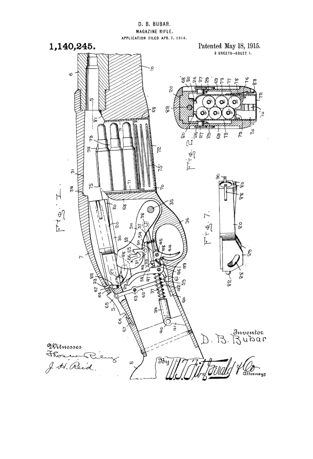
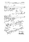
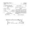
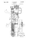
Figure 1 represents a vertical, longitudi-
45 na] sectional view taken through the breech
of a rifle constructed according to my in-
vention, looking from the right hand side
thereof. Fig. 2 represents a vertical trans-
verse sectional view on the line 2—2, Fig. 3.
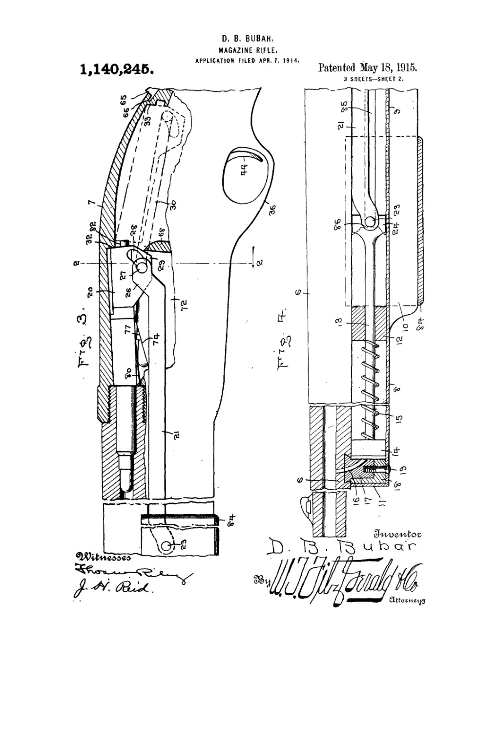
50 Fig. 3 represents a vertical, longitudinal,
sectional view taken through the breech of
a rifle looking at the same from the left
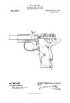
hand side thereof. Fig. 4 represents a side
elevational view of the muzzle of the rifle,
portions thereof being shown in section. 55
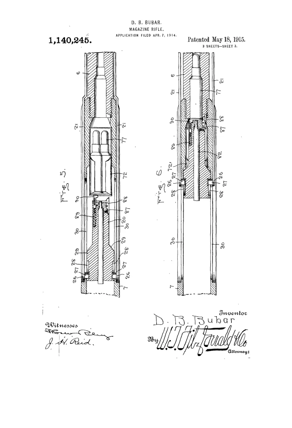
Fig. .5 represents a horizontal sectional view
on the line 5—5, Fig. 1 with breech block
rearward. Fig. 6 represents a horizontal
similar view with breech block advanced.
Fig. 7 is a perspective view of the breech CO
block showing the arcuate slot and the ex-
tractor and ejector.
Referring more particularly to the draw-
ings 5 represents the stock, 6 the barrel and
7 the breech casing of the rifle.' A hollow 65
tube 8 is secured below the barrel 6 of the
rifle in a recess 9 formed in the upper edge
of the 'forward extension 10 of the breech
casing, which tube extends from a point
forwardly of the center of the barrel to the 70
rear end thereof, and said tube is closed at
its forward end 11 and is provided with a
partition 12 in spaced relation to the closed
forward'end, in which partition is guided
a. plunger rod 13, provided at its front end 75
with a piston 14- adapted to be held nor-
mally toward the forward end of the tube
by merfns of 4a spring 15 interposed on the
plunger rod between partition 12 and piston
14, and said piston is adapted to be forced 80
rearwurdly by the expanding gases formed
at the moment of firing, said gases having
entrance to the tube through a port 16
which extends through the underwall of
barrel 6 and through a block 17 dovetailed 85
into said underwall and supported by means
of a second block 18, a screw 19 extending
through the bottom wall of tube 8 through
block 18 and into block 17 for securing the
latter in place. 90
It will be understood of course that pis-
ton 11 will not be operated until the bullet
has passed port-16, but having passed said
port, the expanding gases will enter through
'the port into the forward end of the tube 95
and abut against piston 14, forcing the lat-
ter rearwardly by tire expansion of the
gusec. . 'I'his rearward movement of plunger
rod 13- .rill operate to unseat breech block
20, through the medium of the link 21, piv- lot)
oted as at 23 to the enlarged rear end 24 of
plungejr rod 13, and being offset upwardly
at jts rear end as at 26. said offset 26 pro-
vided with a pin 27 extending on one side
a
1,140,246
thereof, and passing through a slot 30
formed in the wall of the breech casing 7
and engaging an arcuate slot 28 formed in
a depending lug 29 on breech block 20 and
5 it is to be understood that the link, offset,
lug, pin and slots are duplicated at the right
side of the gun for equalizing the force ex-
erted upon the breech block 20 for prevent-
ing any binding action thereof. The breech
10 block is substantially of a rectangular for-
mation, and when in locked position rests
in a recess 31, formed in the upper wall of
. the breech casing rearwardly of barrel 6,
and abuts at its rear end against a substa il-
ls tially square shoulder 32 formed on the up-
per wall of the casing, and rests in a slightly
inclined position as shown in Fig. 3.
Upon rearward movement of plunger 13
and links 21, the pins 27 by engaging the
20 rear walls of slots 28 and at the same time
being guided by slots 30, will force the rear
end of the breech block downwardly out of
engagement with shoulder 32, so that the
block is forced rearwardly into the position
25 shown in dotted lines in Fig. 3 and full
lines in Fig. 1, in which position the block
abuts against a second shoulder 33 formed in
the breech casing. After the breech block
has reached this position and the bullet hav-
30 ing left the muzzle of the rifle, spring 15
expands and • draws plunger 13, and links
21 forwardly, and with them the block the
latter being forced upwardly into locked po-
sition as it reaches the forward end of its
35 movement by reason of pins 27 contacting
with the forward face of the slots 28, as will
be readily understood.
A hammer 34 is pivoted at its lower end
on a pin 35 extending between the side walls
40 of casing 7 forwardly of trigger guard 36,
and a rod 37, is pivoted at its forward end
as at 38 to said hammer, and extends at its
rear end into a tubular guide 39 pivoted as
at 40 bn a lug 41 set into the front edge of
45 stock 5, and a coiled spring 42 is interposed
oil i;od 37 between said guide and a collar 43
secitrtid on. the rod, said spring tending to
normally force the hammer forward. A
trigger 44, is pivoted as at 45 and is provided
50 with a rearwardly extending arm 46 on
which is pivoted the lower end of a lever 47,
a spring 48 which tends to normally hold the
upper end of said lever in a forward posi-
tion being'interposed between a toe 49, on
55 the lower end of said lever and a shoulder
50 formed on the trigger near the pivot point
45 thereof. A three armed sear 51, is piv-
oted as at 52 between the side walls of the
casing, and is provided with a rearwardly
50 extending, forwardly extending, and up-
wardly extending arm 53, 54 and 55 respec-
tively, arm 55 being provided with a tooth
adapted to engage a toothed lug 56 formed
on the upper end of hammer' 34 when said
hammer is forced rearwardly, said arm 55 65
being held normally in a rearward position
by means of a spring 57 interposed between
the forward end of arm 54 and the bottom
of the casing, and the rear end of arm 53
is adapted to be engaged by a shoulder -58 70
on lever 47 when the breech block moves
rearwardly, it being understood that as the
block moves rearwardly the hammer is en-
gaged thereby and forced downwardly,' at
the same time, the curved upper end of lever 75
47 being engaged by the lug 29 for throwing
shoulder 58 out of engagement with arm 53 -
of the sear, and allowing arm 55 thereof to
engage the tooth 56 on the hammer 34 as the
latter is forced downwardly. As the breech 80
block moves forwardly shoulder 58 is en-
gaged under arm 53, and the hammer is held
in cocked position by the engagement of
tooth 56 with the tooth on arm 55' of the
sear, and a pull on trigger 44 will raise the 85
arm 46 on said trigger and with it lever 47,
thereby disengaging arm 55 from tooth 56,
and allowing the hammer to swing for-
wardly by the action of spring 42.. Arm
46 of trigger 44 is normally held in lowered 90
position by means of a leaf spring 59, which
is secured at its rear end to a block 60, m
the bottom wall of the casing, and. which
bears at its forward end on the rearwardly
projecting toe 61 extending from arm ' i. 9S
I have provided a safety lock, cb ii ii com-
prises a lever 62 pivoted interim di ate its
ends as at 63, and which projects j ! its upper
end through a slot 64 formed in ic upper
wall of the breech casing rearwuHily of the 100
shoulder 33 thereon, the upper a d of the
lever being pivoted on a sliding ihiiuib latch
65 provided at opposite ends u it a flanges 66
to engage in recesses 67 formed in the casing,
the lower end of lever 62 terminating in 105
juxtaposition to toe 61 of the trigger, to one
side of spring 59, and is adapted when
latch 65 is moved rearwardly from the posi-
tion shown in Fig. 1 to engage ever said
toe to prevent the trigger from being pulled. 110
The breech casing is provided with a well,
of which partitions 68 and 69 form the walls, •
and this well is adapted to receive the maga,-
ziue 70 which is substantially rectangular,
and which is formed of end walls 71, a but- 115
tom 72 and side walls 73, the hitter at their
upper edges being curved inwardly' toward
each other, and being cut away forwardly
and rearwardly as at 74 and 75 respectively,
and a spring 75' actuates follower 7(> con- 120
tained within the magazine, and is adapted
to normally force the cartridges 77 up-
wardly, the said cartridges being arranged ;
in staggered relation, and occurring in two
vertical series one of which series is sup- 125
ported by one of the steps 78 and the other
by the step 79, which steps form the follower
76. When the magazine is in place, the top-
1,140,345
a
most cartridge is in line with a tongue 80
formed on the lower surface of the breech
block, which tongue is equal in width to
the distance between the upper edges of the
5 side Avail 73 of the magazine, so that as the
breech block moves forwardly the cartridge
is engaged by the tongue and is raised for-
wardly over a beveled surface 81 of the
breech easing into the real' end of the bar-
10 rel, in position for being exploded by the
firing pin 82, as the latter is struck by ham-
mer 34. As the breech block moves rear-
wardly the cartridge is ejected through the
opening 68', and another cartridge is forced
15 into position to be engaged by the block as
it again moves forwardly.
The lugs 29 on the breech block 20 ex-
tend downwardly from each side thereof,
and are engaged when the block is in for-
20 ward position, between the partitions 68 and
69 and the adjacent side Avail of the casing,
and the breech block bears at its sides
against the opposite side Avails of the cas-
ing at the upper portions thereof. The
25 magazine is provided Avith a spring keeper
or latch 83 adapted to engage in a recess
formed in one Avail of the Avell in which the
magazine is positioned.
For operating the breech block by hand,
30 I have provided a block 84, positioned slid-
ably on the forward extension 10 of the
breech casing, and the pin 23 which con-
nects plunger rod 13 and links 21, extends
through slots 85 in the tube 8, and into block
35 84, the pin 23 being normally held against
the shoulders 86 formed upon the inner Avail
of block 84 by the spring 15, so Avhen pl lin-
ger rod 13, pin 23 and links 21 are driven
rearwardly by the pressure of gas, the same
40 are capable of rearward movement inde-
pendent of block 84, while if block 84 is
forced rearAvardly by hand, shoulder 86 en-
gages the ends of pin 23 and forces the pin
23 and links 21 rearwardly so that the rifle
45 may be used as a hand operated arm if so
desired.
Fox' extracting and ejecting the cartridges
or shells I provide the breech block 20
with the recess 87 in which is pivotally
50 mounted the spring actuated extractor 88 at
the right of the firing pin 82. and at the
left side of the firing pin 82, is provided
the bore 89 in Avhich is slidably mounted the
spring actuated ejector 90 for casting the
°5 shells outwardly through the opening 68'
formed in the side of the breech casing 7
after the shells have been withdrawn from
the barrel by the extractor 88.
Although I have described the preferred
60 embodiment of my invention, I may desire
to таке such changes in the construction,
combination and arrangement. of parts as
do not depart from the spirit of the inven-
tion and scope of the appended claims.
Having thus fully described my invention 65
Avhat I claim as iicav and desire to secure by
Letters Patent, is:
1. A magazine rifle, comprising a gun
haxfing a barrel Avith a beveled recess across
the under portion of same Avith a gas passage 70
leading from the rifle bore to said recess and
having a breech block casing connected to
the rear end of the barrel with a breech
block reciprocating therein, a block having
beveled sides inserted in said recess, said 75
block having a bore adapted to register with
the gas passage of said recesses when said
block is properly mounted and leading to
one side of said block, a second block ar-
ranged upon said first block, a tube mounted 80
in said casing having a closed outer end
seated over said blocks with means arranged
therein to fasten said tube to both of said
blocks so that said bore in said first men-
tioned block will communicate Avith said 85
tube, and devices mounted in said tube and -
connected to said breech block adapted to
automatically return to normal position
’after.said devices have been actuated by the
exploded gases of said gun passing into said 90
tube through said gas passage and said bore
in said first mentioned block.
2. A magazine rifle, comprising a gun
having a barrel Avith a breech block casing
attached thereto, a breech block reciprocal- 95
ingly mounted in said casing, a hammer piv-
oted in the lower part of said casing having
means to throw said hummer within the
path of said breech block, said breech block
loAvering said hammer upon the rearward Ю0
reciprocation thereof, a triple-armed sear
pivoted in said casing, one of said arms
adapted to latch said hammer into lowered
position, the second of said arms coactiug
with a spring to retain said first mentioned 105
arm in latching position, a trigger pi voted
in said casing having a lugged arm, a level'
pivoted upon said arm and cooperating with
the third arm of said sear to unlatch said
first mentioned arm to release sqid hammer, HO
said level' having a spring mounted between
the lug on said trigger arm and the end of
said lever adapted to engage said lever with
said third arm of said sear.
3. A magazine rifle, comprising a gun ha v- 115
ing_ a breech block casing Avith a breech block
reciprocatingly mounted therein, a ham-
mer .pivoted therein adapted to be lowered
by said breech block, pivoted means mount-
ed in said casing adapted to'lock said ham- 120
mer into lowered position, a trigger pivoted
in said casing having an arm thereto vvith
a pivoted lever arranged thereupon adapt-
ed to unlock said hammer locking means,
and means pivoted in said casing, adapted at 125
one end to engage said trigger arm to pre-
vent the operation of said trigger, and at the
opposite end pivotally connected Avith a
1,140,246
thumb latch adapted to move said pivoted
means into or out of engagement with said
trigger arm, said thumb latch having op-
positely disposed flanges adapted to slid-
5 ingly seat in suitable recesses in said casing
to retain said thumb latch in position.
In testimony whereof I have signed my
name to this specification in the presence of
two subscribing witnesses.
DEAN BRABSON BUBAR.
Witnesses:
George W. Young,
Roy O. Young.