/
Tags: weapons military affairs
Year: 1965


Text
FM 23-5
DEPARTMENT OF THE ARMY FIELD MANUAL
U.S. RIFLE
CALIBER .30, Ml
HEADQUARTERS, DEPARTMENT OF THE ARMY
MAY 1965
*FM 23-5
Field Manual
No. 23-5
HEADQUARTERS
DEPARTMENT OF THE ARMY
Washington, D.C., 17 May 1965
U.S. RIFLE, CALIBER .30, Ml
Paragraph» Page
Chapter 1. INTRODUCTION_________________________________________ 1- 4
2. MECHANICAL TRAINING_________________________________ 5-11
3. OPERATION AND FUNCTIONING__________________________ 12-15
4. STOPPAGES AND IMMEDIATE ACTION_____________________ 15-19
5. MAINTENANCE________________________________________ 20-24
6. AMMUNITION___________________________________________ 25,26
Appendix I. REFERENCES__________________________________________ ____
to TF о © ю <©
м м N N «
♦This manual supersedes FM 23—5, 26 September 1958, including Cl, 22 June 1960.
1
CHAPTER 1
INTRODUCTION
1. Purpose and Scope
a. This manual is a guide for commanders and
instructors in presenting instruction and training
in the mechanical operation of the Ml rifle. It
includes a detailed description of the rifle and its
general characteristics; procedures for disassem-
bly and assembly; methods of loading; an ex-
planation of functioning; a discussion of stop-
pages and immediate action; a description of the
ammunition; and instructions on the care and
cleaning of both the weapon and ammunition.
The material presented is applicable, without
modification, to both nuclear and nonnuclear
warfare.
b. Marksmanship training is covered in FM
23-71.
c. Users of this manual are encouraged to sub-
mit recommended changes or comments to im-
prove the manual. Comments should be keyed to
the specific page, paragraph, and line of the text
in which the change is recommended. Reasons
should be provided for each comment to insure
understanding and complete evaluation. Com-
ments should be forwarded direct to the Com-
mandant, U.S. Army Infantry School, Fort Ben-
ning, Ga.
2. Importance of Mechanical Training
The rifle is the soldier’s basic weapon. It gives
him an individual and powerful capability for
combat. To get the most out of his individual
combat capability, the soldier must develop two
skills to an equal degree: he must be able to fire
his weapon well enough to get hits on battlefield
targets, and he must know enough about its
working parts to keep them operating smoothly
so the rifle will not fail him. The soldier gets his
firing skill on marksmanship training ranges and
he learns how to keep his rifle in firing condition
from the mechanical training that is outlined in
this manual.
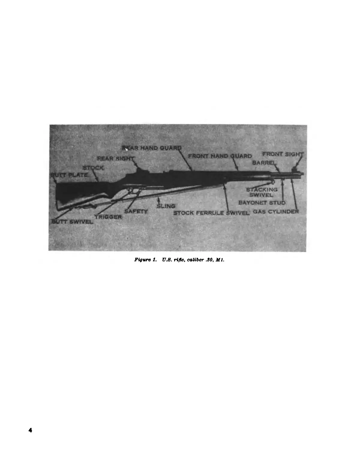
3. Description of the Rifle
The U.S. rifle caliber .30, Ml, (fig. 1) is an
air-cooled, gas-operated, clip-fed, and semiauto-
matic shoulder weapon. This means that the air
cools the barrel; that the power to cock the rifle
and chamber the succeeding round comes from
the expanding gas of the round fired previously;
that it is loaded by inserting a metal clip (con-
taining a maximum of eight rounds) into the re-
ceiver ; and that the rifle fires one round each time
the trigger is pulled.
4. General Data
Weight:
Complete with sling, eight-
round clip and cleaning
equipment (approximate). 11% pounds.
Length:
Overall _________________________43 Inches.
Sights:
Front____________________________Fixed.
Rear_________________________Adjustable. One click
of elevation or wind-
age moves the strike
of the bullet .7 centi-
meters at 25 meters.
Trigger pull:
Minimum ___________________5% pounds.
Maximum____________________7% pounds.
Ammunition_____________________See chapter 6.
Muzzle velocity (approximately). 853 meters (2,800 feet)
per second.
Chamber pressure_______________ 50,000 pounds per
square Inch.
Maximum range__________________ 3,200 meters.
Maximum effective range1------- 460 meters.
Maximum effective rate of Are 16 to 24 rounds per
minute.
1 Maximum effective range Is the greatest distance at which a
weapon may be expected to Are accurately to Inflict casualties or
damage.
1 Although there Is no prescribed maximum rate of Are, a
trained rifleman can Are 16 to 24 aimed rounds per minute.
3
Figure 1. U.S. rifle, caliber .SO, Ml.
4
CHAPTER 2
MECHANICAL TRAINING
5. Disassembly and Assembly
a. The individual soldier is authorized to dis-
assemble his rifle to the extent called field strip-
ping. Table I, Disassembly Authorization (para.
7), shows the parts he is permitted to disassemble.
This amount of disassembly is necessary for nor-
mal maintenance.
b. The rifle should be disassembled and assem-
bled only when maintenance is required or for in-
structional purposes. Repeated disassembly and
assembly causes excessive wear of parts and soon
makes them unserviceable and reduces the ac-
curacy of the weapon.
c. The rifle has been designed so that it may be
taken apart and put together easily. No force is
needed if it is disassembled and assembled cor-
rectly. The parts of one rifle, except the bolt,
may be interchanged with those of another when
necessary; for safety reasons, bolts should never
be interchanged except by maintenance support
personnel.
d. As the rifle is disassembled, the parts should
be laid out on a clean surface, in the order of re-
moval, from left to right. This makes assembly
easier because the parts are assembled in the re-
verse order of disassembly. The names of the
rifle parts (nomenclature) should be taught along
with disassembly and assembly to make future
instruction on the rifle easier to understand.
6. Clearing the Rifle
The first step in handling any weapon is to
clear it. If the rifle is loaded, unload it as de-
scribed in paragraph 13. The Ml rifle is clear
when there is no ammunition in the chamber or
receiver, the bolt is locked to the rear, and the
safety is engaged. To clear the rifle, pull the
operating rod handle all the way to the rear, in-
spect the chamber and receiver to insure that no
rounds are present and push the safety to its
locked position (inside the trigger guard).
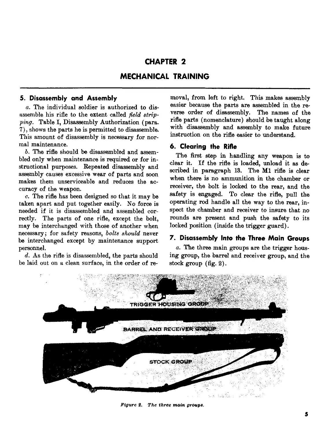
7. Disassembly Into the Three Main Groups
a. The three main groups are the trigger hous-
ing group, the barrel and receiver group, and the
stock group (fig. 2).
Figure 2. The three main groups.
5
Ъ. То disassemble the rifle into the three main
groups, first insure that the weapon is clear and
then allow the bolt to go forward by depressing
the follower with the right thumb and allowing
the bolt to ride forward over the follower
assembly.
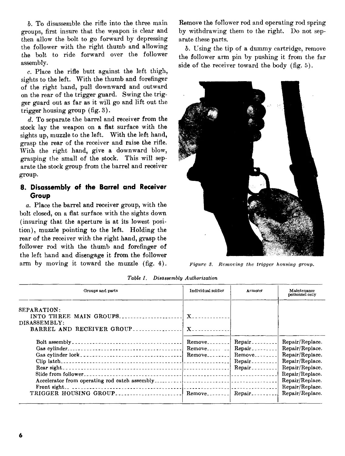
c. Place the rifle butt against the left thigh,
sights to the left. With the thumb and forefinger
of the right hand, pull downward and outward
on the rear of the trigger guard. Swing the trig-
ger guard out as far as it will go and lift out the
trigger housing group (fig. 3).
d. To separate the barrel and receiver from the
stock lay the weapon on a flat surface with the
sights up, muzzle to the left. With the left hand,
grasp the rear of the receiver and raise the rifle.
With the right hand, give a downward blow,
grasping the small of the stock. This will sep-
arate the stock group from the barrel and receiver
group.
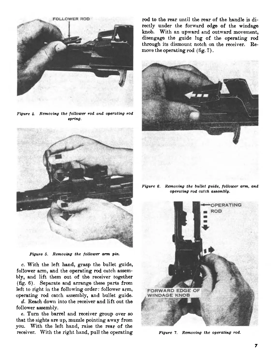
8. Disassembly of the Barrel and Receiver
Group
a. Place the barrel and receiver group, with the
bolt closed, on a flat surface with the sights down
(insuring that the aperture is at its lowest posi-
tion), muzzle pointing to the left. Holding the
rear of the receiver with the right hand, grasp the
follower rod with the thumb and forefinger of
the left hand and disengage it from the follower
arm by moving it toward the muzzle (fig. 4).
Remove the follower rod and operating rod spring
by withdrawing them to the right. Do not sep-
arate these parts.
Ъ. Using the tip of a dummy cartridge, remove
the follower arm pin by pushing it from the far
side of the receiver toward the body (fig. 5).
Figure 3. Removing the trigger housing group.
Table I. Disassembly Authorization
Groups and parts Individual soldier Armorer Maintenance personnel only
SEPARATION: INTO THREE DISASSEMBLY: BARREL AND MAIN GROUPS RECEIVER GROUP и и 1 1 1 1 1 1 1 1 1 1 1 1 1 1 1 1 1 1 1 1 1 1 1 1
Bolt assembly Gas cylinder Gas cylinder lock Clip latch Rear sight Slide from follower Accelerator from operating rod catch assembly Front sight.. TRIGGER HOUSING GROUP Remove Remove Remove Remove Repair Repair Remove Repair Repair Repair Repair/Replace. Repair/Replace. Repair/Replace. Repair/Replace. Repair/Replace. Repair/Replace. Repair/Replace. Repair/Replace. Repair/ Replace.
6
Figure 4. Removing the follower rod and operating rod
spring.
Figure 5. Removing the follower arm pin.
c. With the left hand, grasp the bullet guide,
follower arm, and the operating rod catch assem-
bly, and lift them out of the receiver together
(fig. 6). Separate and arrange these parts from
left to right in the following order: follower arm,
operating rod catch assembly, and bullet guide.
d. Reach down into the receiver and lift out the
follower assembly.
e. Turn the barrel and receiver group over so
that the sights are up, muzzle pointing away from
you. With the left hand, raise the rear of the
receiver. With the right hand, pull the operating
rod to the rear until the rear of the handle is di-
rectly under the forward edge of the windage
knob. With an upward and outward movement,
disengage the guide lug of the operating rod
through its dismount notch on the receiver. Re-
move the operating rod (fig. 7).
Figure 6. Removing the bullet guide, follower arm, and
operating rod catch assembly.
Figure 7. Removing the operating rod.
7
Caution: The operating rod is bent inten-
tionally so that it will not bind against the
enlarged portion of the barrel. Do not attempt
to straighten it.
/. With the right hand, grasp the bolt by the
operating lug and slide it fully to the rear; then
slide it forward, lifting upward and outward to
the right front with a slight rotating motion to
remove it.
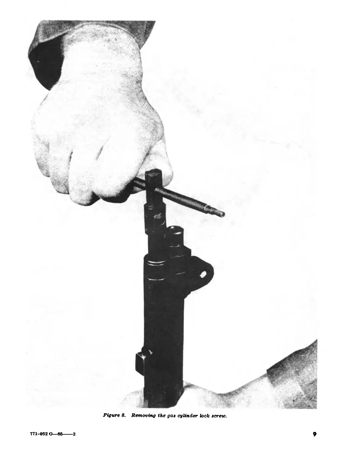
g. Using the screwdriver blade of the MIO
cleaning rod handle as shown in figure 8, unscrew
and remove the gas cylinder lock screw.
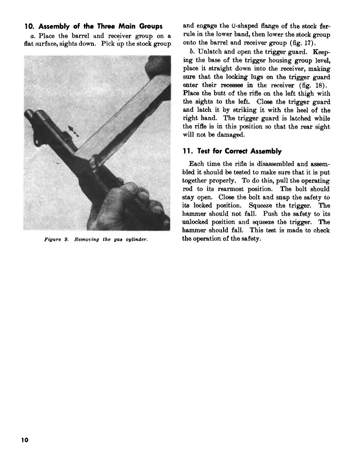
h. Unscrew and remove the gas cylinder lock.
Loosen the gas cylinder by tapping lightly toward
the muzzle on the bayonet stud with a piece of
wood or similar soft object (fig. 9). Remove the
gas cylinder, taking care not to burr or damage
the splines. Do not remove or attempt to adjust
the front sight.
i. Remove the front handguard by sliding it
forward over the muzzle. Do not attempt to re-
move the rear handguard.
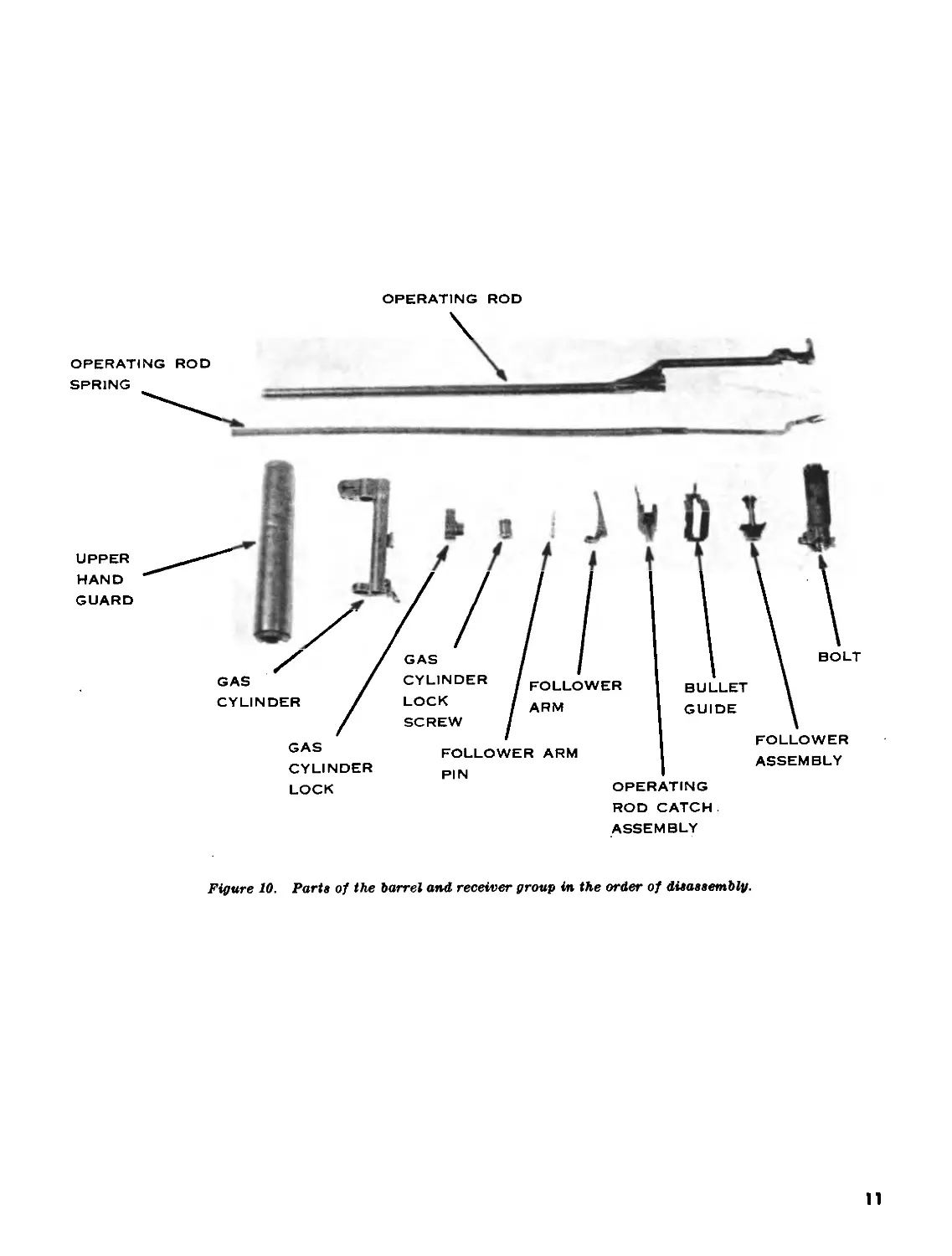
j. The parts of the barrel and receiver group
in their order of disassembly are shown in figure
10.
9. Assembly of the Barrel and Receiver
Group
a. Replace the front handguard by sliding it
over the muzzle and insure that it is seated in the
front band.
Ъ. Place the gas cylinder over the barrel, mak-
ing sure the splines are alined with their grooves.
Push the gas cylinder down as far as it will go.
If tapping is necessary, use a piece of wood on the
bayonet stud. Engage the threads of the gas
cylinder lock with those on the barrel and screw
the lock on by hand until it is finger tight (do not
use a tool). If the lock is not alined with the gas
cylinder, do not force it, but unscrew it until it is
alined. Replace and tighten the gas cylinder lock
screw with the handle assembly of the MIO clean-
ing rod.
c. To replace the bolt, hold it by the operating
lug and place the rear end of the bolt onto the
bridge of the receiver. Rotate the bolt counter-
clockwise as far as necessary to permit the tang
of the firing pin to clear the top of the bridge of
the receiver. Guide the left locking lug of the
bolt into its groove on the left side of the receiver.
Lower the right locking lug on its bearing sur-
face and slide the bolt halfway to the rear.
d. To replace the operating rod, hold the han-
dle with the right hand and place the piston end
into the gas cylinder. Aline the operating rod
so that the recess in the hump fits over the operat-
ing lug of the bolt. While applying pressure
downward and inward on the handle, pull the op-
erating rod to the rear until the guide lug is en-
gaged in its groove (fig. 11). Move the operating
rod forward until the bolt is closed.
e. Turn the barrel and receiver group over so
that the sights are down and the muzzle is to the
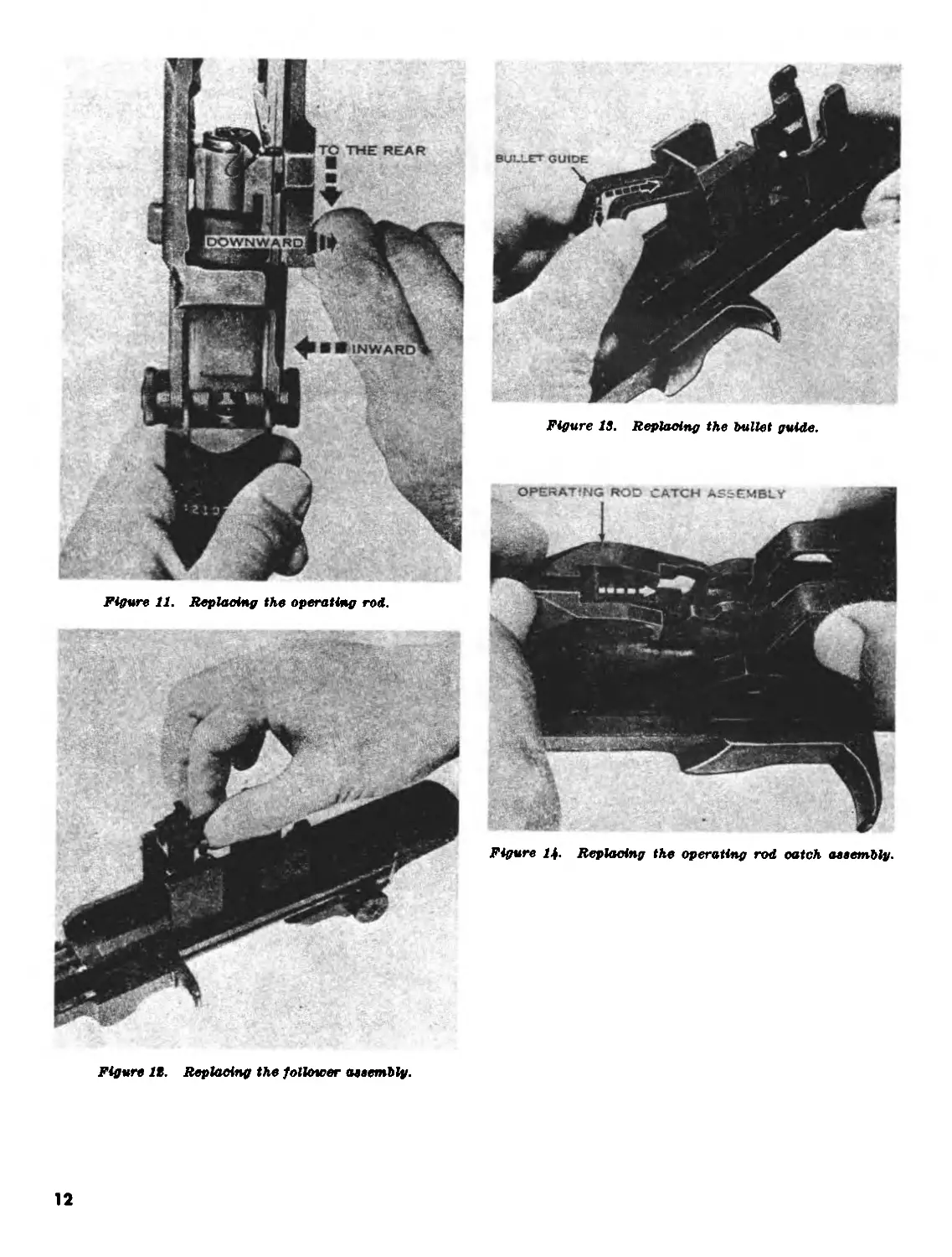
left. Replace the follower assembly so that its
guide ribs fit into their grooves in the receiver.
Make sure that the slide of the follower is down
and that the square hole is to the rear (fig. 12).
The slide will rest against the bolt.
f. Replace the bullet guide so that its shoulders
fit into their slots in the receiver and the hole in
the toe of the bullet guide is alined with the holes
in the receiver (fig. 13).
g. With the right hand, lift up the lower part
of the bullet guide slightly. With the left hand,
insert the rear arm of the operating rod catch as-
sembly through the clearance cut in the side of
the bullet guide. Make sure that the rear arm is
underneath the front stud of the clip latch which
projects into the receiver (fig. 14). Lower the
bullet guide into place. Test for correct assembly
by pressing down on the front arms of the operat-
ing rod catch assembly. It should move and you
should be able to feel the tension of the clip latch
spring.
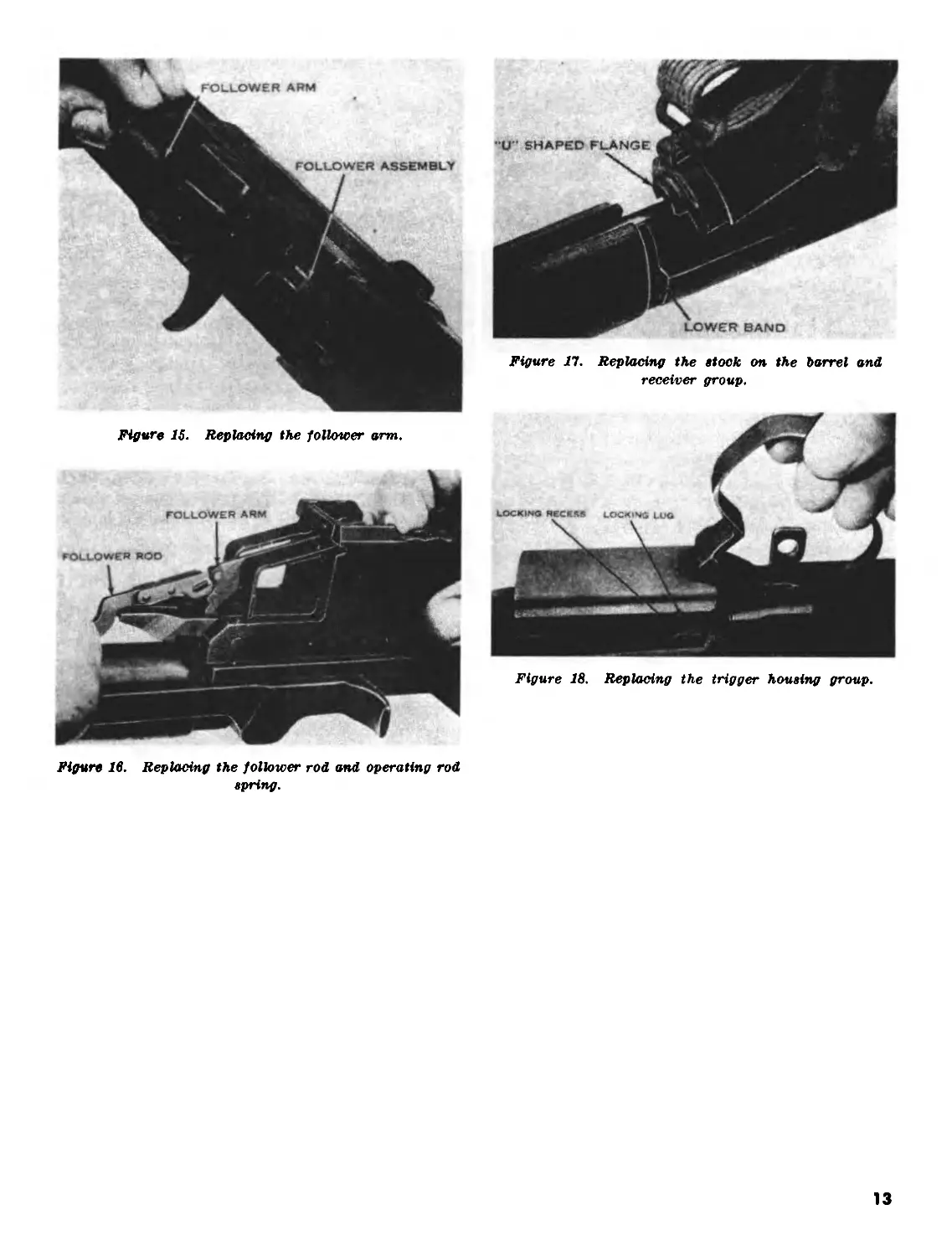
h. Replace the follower arm by passing its rear
studs through the bullet guide and inserting them
into the guide grooves on the follower (fig. 15).
Allow the wings of the follower arm to rest astride
the toe of the bullet guide. Aline the holes in the
operating rod catch assembly, follower arm, and
bullet guide with those in the receiver and replace
the follower arm pin from the near side.
i. Insert the loose end of the operating rod
spring into the operating rod. Grasp the follower
rod with the left hand, making sure that its hump
is toward the barrel. Pull toward the muzzle,
compressing the operating rod spring, and engage
the claws of the follower rod with the front studs
of the follower arm (fig. 16). You may have to
raise the follower assembly to do this.
8
Figure 8.
Removing the gas cylinder lock screw.
9
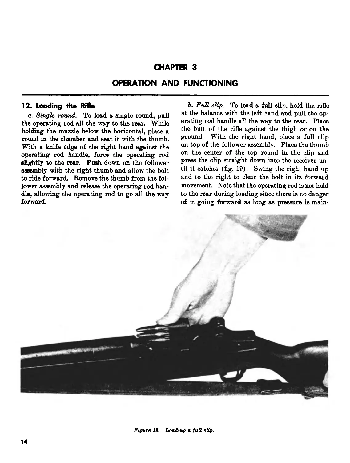
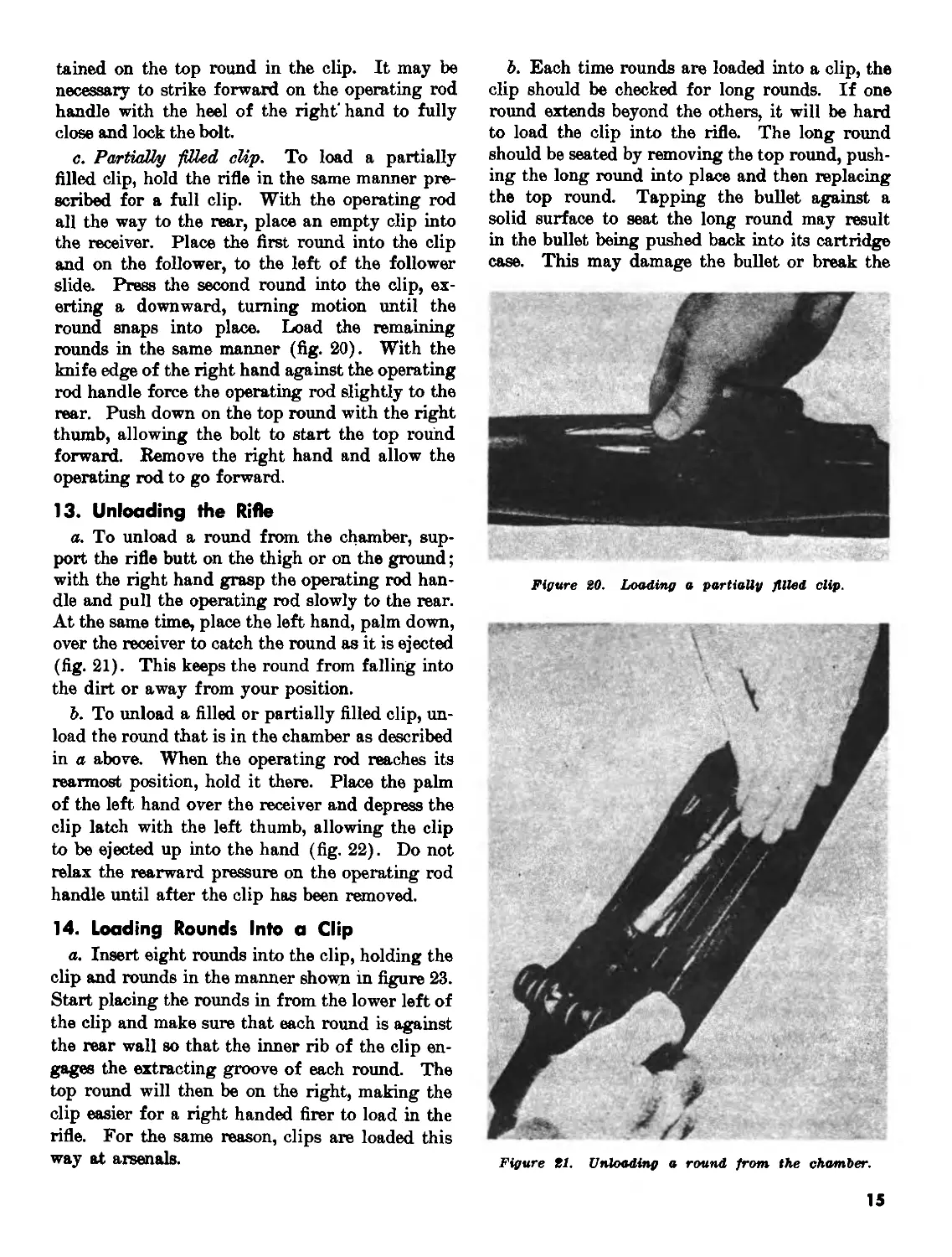
10. Assembly of the Three Main Groups
a. Place the barrel and receiver group on a
flat surface, sights down. Pick up the stock group
Figure 9. Removing the gas cylinder.
and engage the U-shaped flange of the stock fer-
rule in the lower band, then lower the stock group
onto the barrel and receiver group (fig. 17).
b. Unlatch and open the trigger guard. Keep-
ing the base of the trigger housing group level,
place it straight down into the receiver, making
sure that the locking lugs on the trigger guard
enter their recesses in the receiver (fig. 18).
Place the butt of the rifle on the left thigh with
the sights to the left. Close the trigger guard
and latch it by striking it with the heel of the
right hand. The trigger guard is latched while
the rifle is in this position so that the rear sight
will not be damaged.
11. Test for Correct Assembly
Each time the rifle is disassembled and assem-
bled it should be tested to make sure that it is put
together properly. To do this, pull the operating
rod to its rearmost position. The bolt should
stay open. Close the bolt and snap the safety to
its locked position. Squeeze the trigger. The
hammer should not fall. Push the safety to its
unlocked position and squeeze the trigger. The
hammer should fall. This test is made to check
the operation of the safety.
10
OPERATING ROD
ROD CATCH .
ASSEMBLY
Figure 10. Parts о/ the barrel and receiver group in the order of disassembly.
11
Figure it. Replacing the follower aeeemhlg.
Figure IS. Replacing the bullet guide.
Figure Ц. Replacing the operating rod catch aeeemblg.
12
Figure 1в. Replacing the follower rod and operating rod
spring.
13
CHAPTER 3
OPERATION AND FUNCTIONING
12. Loading the Rifle
a. Single round. To load a single round, pull
the operating rod all the way to the rear. While
holding the muzzle below the horizontal, place a
round in the chamber and seat it with the thumb.
With a knife edge of the right hand against the
operating rod handle, force the operating rod
slightly to the rear. Push down on the follower
assembly with the right thumb and allow the bolt
to ride forward. Romove the thumb from the fol-
lower assembly and release the operating rod han-
dle, allowing the operating rod to go all the way
forward.
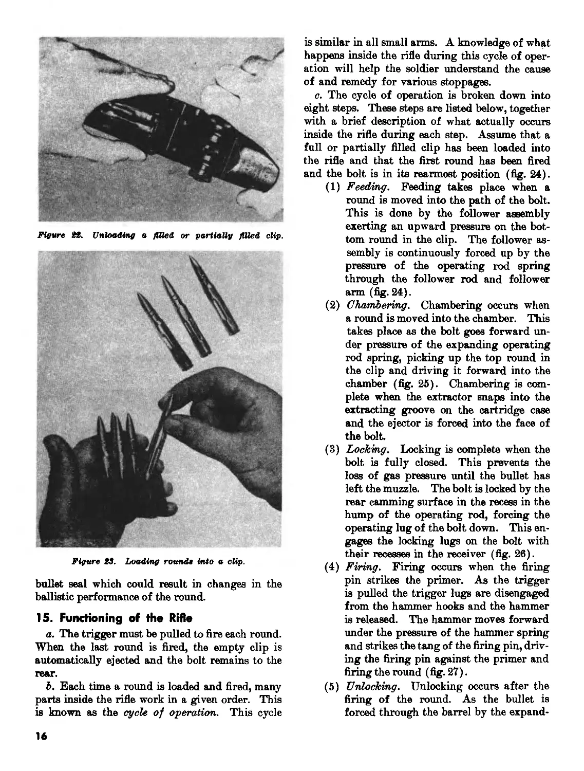
b. Full clip. To load a full clip, hold the rifle
at the balance with the left hand and pull the op-
erating rod handle all the way to the rear. Place
the butt of the rifle against the thigh or on the
ground. With the right hand, place a full clip
on top of the follower assembly. Place the thumb
on the center of the top round in the clip and
press the clip straight down into the receiver un-
til it catches (fig. 19). Swing the right hand up
and to the right to clear the bolt in its forward
movement. Note that the operating rod is not held
to the rear during loading since there is no danger
of it going forward as long as pressure is main-
Figure IS. Loading a full cUp.
tained on the top round in the clip. It may be
necessary to strike forward on the operating rod
handle with the heel of the right'hand to fully
close and lock the bolt.
c. PartiaXby filled clip. To load a partially
filled clip, hold the rifle in the same manner pre-
scribed for a full clip. With the operating rod
all the way to the rear, place an empty clip into
the receiver. Place the first round into the clip
and on the follower, to the left of the follower
slide. Press the second round into the clip, ex-
erting a downward, turning motion until the
round snaps into place. Load the remaining
rounds in the same manner (fig. 20). With the
knife edge of the right hand against the operating
rod handle force the operating rod slightly to the
rear. Push down on the top round with the right
thumb, allowing the bolt to start the top round
forward. Remove the right hand and allow the
operating rod to go forward.
13. Unloading the Rifle
a. To unload a round from the chamber, sup-
port the rifle butt on the thigh or on the ground;
with the right hand grasp the operating rod han-
dle and pull the operating rod slowly to the rear.
At the same time, place the left hand, palm down,
over the receiver to catch the round as it is ejected
(fig. 21). This keeps the round from falling into
the dirt or away from your position.
b. To unload a filled or partially filled clip, un-
load the round that is in the chamber as described
in a above. When the operating rod reaches its
rearmost position, hold it there. Place the palm
of the left hand over the receiver and depress the
clip latch with the left thumb, allowing the clip
to be ejected up into the hand (fig. 22). Do not
relax the rearward pressure on the operating rod
handle until after the clip has been removed.
14. Loading Rounds Into a Clip
a. Insert eight rounds into the clip, holding the
clip and rounds in the manner shown in figure 23.
Start placing the rounds in from the lower left of
the clip and make sure that each round is against
the rear wall so that the inner rib of the clip en-
gages the extracting groove of each round. The
top round will then be on the right, making the
clip easier for a right handed firer to load in the
rifle. For the same reason, clips are loaded this
way at arsenals.
b. Each time rounds are loaded into a clip, the
clip should be checked for long rounds. If one
round extends beyond the others, it will be hard
to load the clip into the rifle. The long round
should be seated by removing the top round, push-
ing the long round into place and then replacing
the top round. Tapping the bullet against a
solid surface to seat the long round may result
in the bullet being pushed back into its cartridge
case. This may damage the bullet or break the
Figure 20. Loading a partially filled clip.
Figure 21. Unloading a round from the chamber.
15
Figure №. Unloading a filled or partially filled clip.
Figure IS. Loading round» into a clip.
bullet seal which could result in changes in the
ballistic performance of the round.
15. Functioning of the Rifle
a. The trigger must be pulled to fire each round.
When the last round is fired, the empty clip is
automatically ejected and the bolt remains to the
rear.
b. Each time a round is loaded and fired, many
parts inside the rifle work in a given order. This
is known as the cycle of operation. This cycle
is similar in all small arms. A knowledge of what
happens inside the rifle during this cycle of oper-
ation will help the soldier understand the cause
of and remedy for various stoppages.
c. The cycle of operation is broken down into
eight steps. These steps are listed below, together
with a brief description of what actually occurs
inside the rifle during each step. Assume that a
full or partially filled clip has been loaded into
the rifle and that the first round has been fired
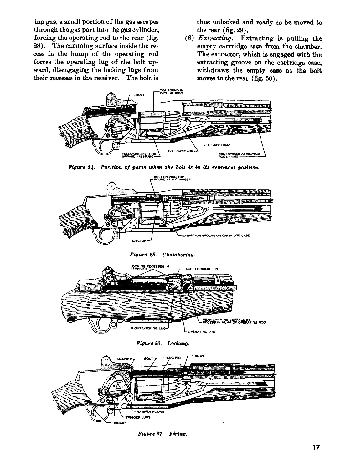
and the bolt is in its rearmost position (fig. 24).
(1) Feeding. Feeding takes place when a
round is moved into the path of the bolt.
This is done by the follower assembly
exerting an upward pressure on the bot-
tom round in the clip. The follower as-
sembly is continuously forced up by the
pressure of the operating rod spring
through the follower rod and follower
arm (fig. 24).
(2) Chambering. Chambering occurs when
a round is moved into the chamber. This
takes place as the bolt goes forward un-
der pressure of the expanding operating
rod spring, picking up the top round in
the clip and driving it forward into the
chamber (fig. 25). Chambering is com-
plete when the extractor snaps into the
extracting groove on the cartridge case
and the ejector is forced into the face of
the bolt.
(3) Locking. Locking is complete when the
bolt is fully closed. This prevents the
loss of gas pressure until the bullet has
left the muzzle. The bolt is locked by the
rear camming surface in the recess in the
hump of the operating rod, forcing the
operating lug of the bolt down. This en-
gages the locking lugs on the bolt with
their recesses in the receiver (fig. 26).
(4) Firing. Firing occurs when the firing
pin strikes the primer. As the trigger
is pulled the trigger lugs are disengaged
from the hammer hooks and the hammer
is released. The hammer moves forward
under the pressure of the hammer spring
and strikes the tang of the firing pin, driv-
ing the firing pin against the primer and
firing the round (fig. 27).
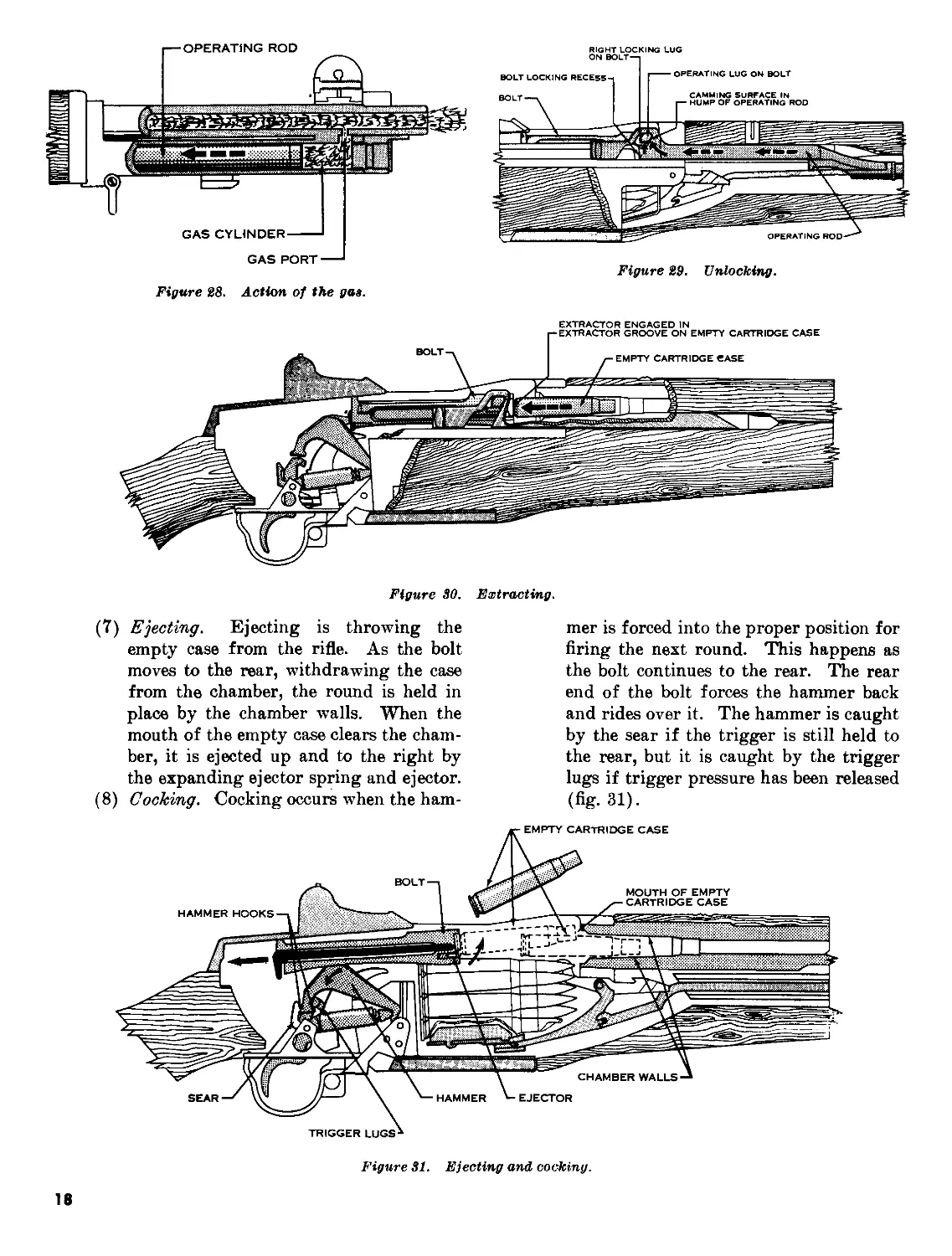
(5) Unlocking. Unlocking occurs after the
firing of the round. As the bullet is
forced through the barrel by the expand-
16
ing gas, a small portion of the gas escapes
through the gas port into the gas cylinder,
forcing the operating rod to the rear (fig.
28). The camming surface inside the re-
cess in the hump of the operating rod
forces the operating lug of the bolt up-
ward, disengaging the locking lugs from
their recesses in the receiver. The bolt is
thus unlocked and ready to be moved to
the rear (fig. 29).
(6) Extracting. Extracting is pulling the
empty cartridge case from the chamber.
The extractor, which is engaged with the
extracting groove on the cartridge case,
withdraws the empty case as the bolt
moves to the rear (fig. 30).
Figure Hf- Position of parts when the bolt is in its rearmost position.
BOLT DRIVING TOP
Figure 25. Chambering.
Figure 26. Looking.
Figure 27. Firing.
17
Figure 28. Action of the да».
RIGHT LOCKING LUG
ON BOLT—
BOLT LOCKING RECESS-.
----OPERATING LUG ON BOLT
Figure 29. Unlocking.
Figure 30. Extracting.
(7) Ejecting. Ejecting is throwing the
empty case from the rifle. As the bolt
moves to the rear, withdrawing the case
from the chamber, the round is held in
place by the chamber walls. When the
mouth of the empty case clears the cham-
ber, it is ejected up and to the right by
the expanding ejector spring and ejector.
(8) Cocking. Cocking occurs when the ham-
mer is forced into the proper position for
firing the next round. This happens as
the bolt continues to the rear. The rear
end of the bolt forces the hammer back
and rides over it. The hammer is caught
by the sear if the trigger is still held to
the rear, but it is caught by the trigger
lugs if trigger pressure has been released
(fig. 31).
Figure 31. Ejecting and cocking.
18
CHAPTER 4
STOPPAGES AND IMMEDIATE ACTION
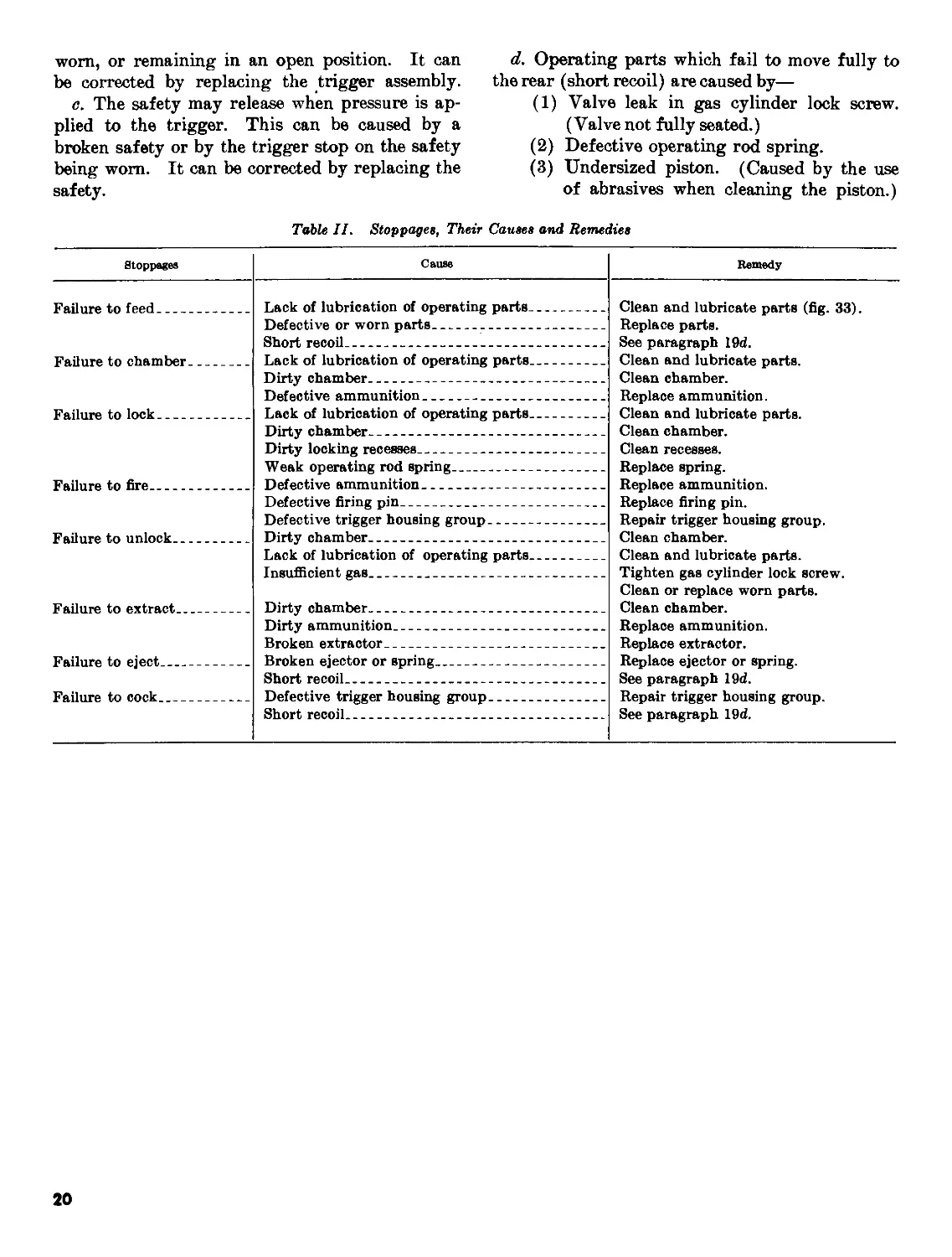
16. Stoppages
a. A stoppage is any unintentional interruption
in the cycle of operation.
b. Most stoppages occur because of dirty, worn,
or broken parts, and lack of lubrication. The
rifleman must be taught to watch for these de-
fects and take corrective action to eliminate them
before they cause a stoppage. Some of the more
common stoppages, with their usual causes and
remedies, are shown in table II (para 19). Note
that the stoppages are classified according to the
steps of the cycle of operation.
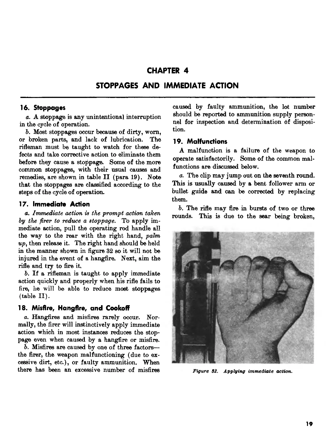
17. Immediate Action
a. Imtmediate action is the prompt action taken
by the firer to reduce a stoppage. To apply im-
mediate action, pull the operating rod handle all
the way to the rear with the right hand, palm,
up, then release it. The right hand should be held
in the manner shown in figure 32 so it will not be
injured in the event of a hangfire. Next, aim the
rifle and try to fire it.
b. If a rifleman is taught to apply immediate
action quickly and properly when his rifle fails to
fire, he will be able to reduce most stoppages
(table II).
18. Misfire, Hangfire, and Cookoff
a. Hangfires and misfires rarely occur. Nor-
mally, the firer will instinctively apply immediate
action which in most instances reduces the stop-
page even when caused by a hangfire or misfire.
b. Misfires are caused by one of three factors—
the firer, the weapon malfunctioning (due to ex-
cessive dirt, etc.), or faulty ammunition. When
there has been an excessive number of misfires
caused by faulty ammunition, the lot number
should be reported to ammunition supply person-
nel for inspection and determination of disposi-
tion.
19. Malfunctions
A malfunction is a failure of the weapon to
operate satisfactorily. Some of the common mal-
functions are discussed below.
a. The clip may jump out on the seventh round.
This is usually caused by a bent follower arm or
bullet guide and can be corrected by replacing
them.
b. The rifle may fire in bursts of two or three
rounds. This is due to the sear being broken,
Figure 82. Applying immediate action.
19
worn, or remaining in an open position. It can
be corrected by replacing the trigger assembly.
c. The safety may release when pressure is ap-
plied to the trigger. This can be caused by a
broken safety or by the trigger stop on the safety
being worn. It can be corrected by replacing the
safety.
d. Operating parts which fail to move fully to
the rear (short recoil) are caused by—
(1) Valve leak in gas cylinder lock screw.
(Valve not fully seated.)
(2) Defective operating rod spring.
(3) Undersized piston. (Caused by the use
of abrasives when cleaning the piston.)
Table II. Stoppages, Their Causes and Remedies
Stoppages Cause Remedy
Failure to feed Failure to chamber Failure to lock Failure to fire - _ Lack of lubrication of operating parts Defective or worn parts Short recoil Lack of lubrication of operating parts Dirty chamber Defective ammunition Lack of lubrication of operating parts Dirty chamber Dirty locking recesses Weak operating rod spring Defective ammunition Clean and lubricate parts (fig. 33). Replace parts. See paragraph 19d. Clean and lubricate parts. Clean chamber. Replace ammunition. Clean and lubricate parts. Clean chamber. Clean recesses. Replace spring. Replace ammunition. Replace firing pin. Repair trigger housing group. Clean chamber. Clean and lubricate parts. Tighten gas cylinder lock screw. Clean or replace worn parts. Clean chamber.
Failure to unlock Failure to extract Defective firing pin Defective trigger housing group Dirty chamber Lack of lubrication of operating parts Insufficient gas Dirty chamber
Failure to eject Failure to cock Dirty ammunition Broken extractor Broken ejector or spring Short recoil Defective trigger housing group Short recoil Replace ammunition. Replace extractor. Replace ejector or spring. See paragraph 19d. Repair trigger housing group. See paragraph 19d.
20
CHAPTER 5
MAINTENANCE
20. General
Maintenance includes all measures taken to keep
the rifle in operating condition. This includes
normal cleaning, inspection for defective parts, re-
pair, and lubrication.
21. Cleaning Materials, Lubricants, and
Equipment
a. Cleaning Materials.
(1) Bore cleaner (cleaning compound solvent
(CR)) is used primarily for cleaning the
bore; however, it may be used on all metal
parts for a temporary (1-day) protection
from rust.
(2) Hot, soapy water or boiling water is no
substitute for bore cleaner and will only
be used when bore cleaner is not available.
(3) Drycleaning solvent is used for cleaning
rifles which are coated with grease, oil,
or corrosion-preventive compounds.
(4) Stubborn carbon deposits are removed by
soaking in carbon removing compound
(PCIII-A) and brushing. This process
must be followed by the use of dryclean-
ing solvent.
Caution: Individual protective meas-
ures must be taken when using com-
pound PCIII-A.
b. Lubricants.
(1) Lubricating oil, general purpose (PL
special) is used for lubricating the rifle
at normal temperatures.
(2) Lubricating oil, weapons (LAW) is used
for low temperatures (below 0°).
(3) OE 10 engine oil may be used as a field
expedient under combat conditions when
the oils prescribed in (1) and (2) above
cannot be obtained. However, the
weapon should be cleaned and lubricated
with the proper lubricants as soon as
possible.
(4) Rifle grease should be applied to those
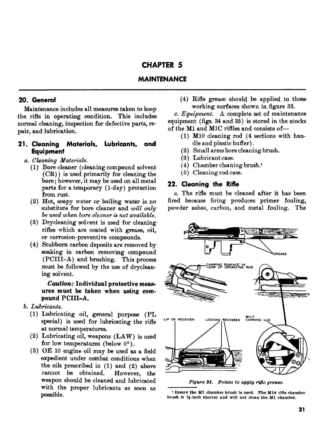
working surfaces shown in figure 33.
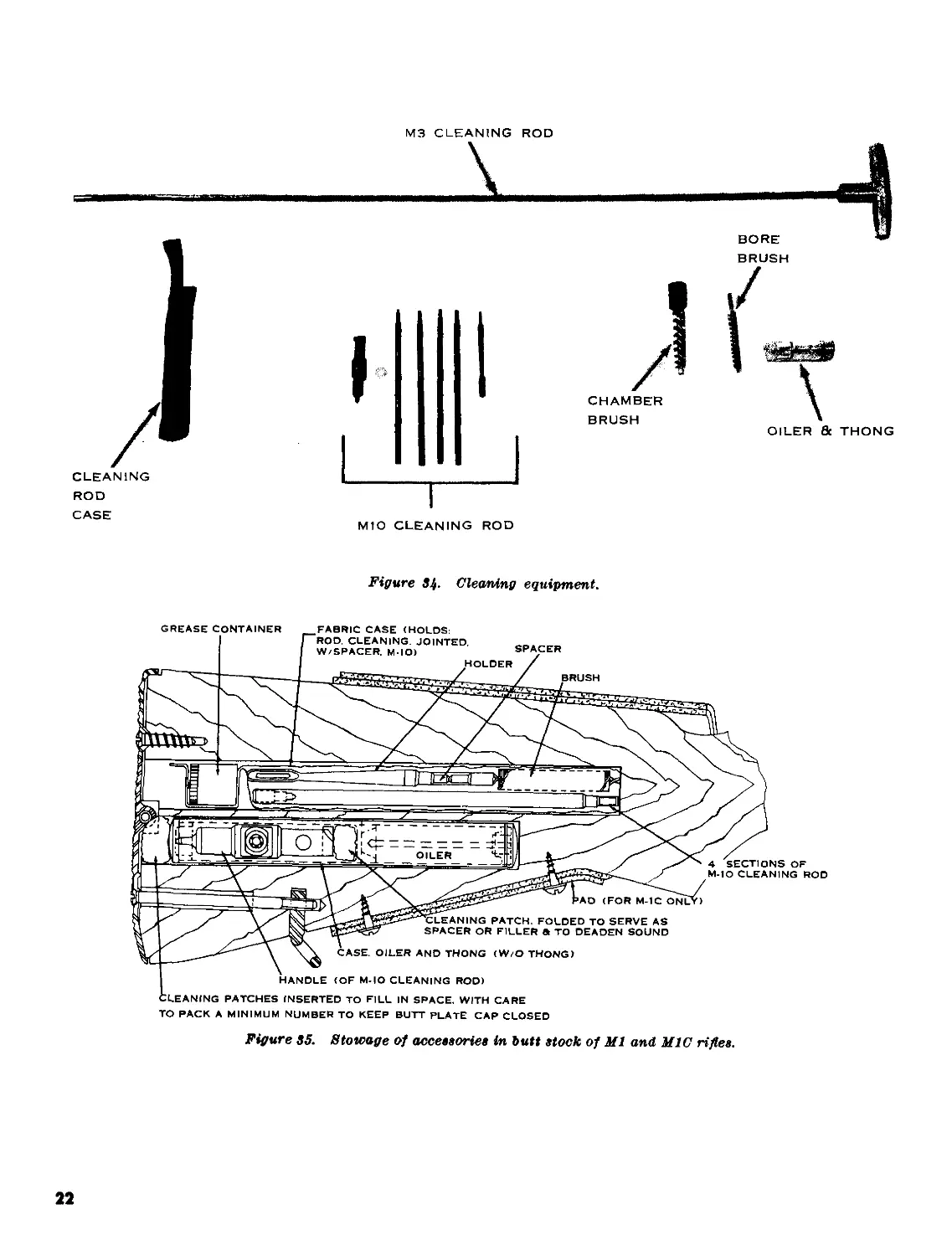
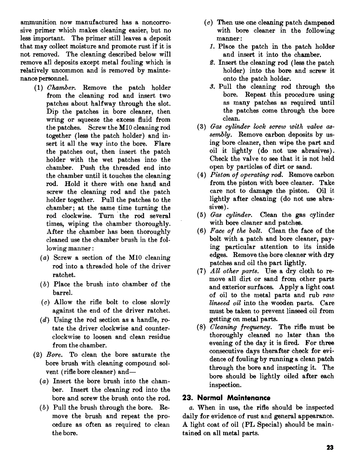
c. Equipment. A complete set of maintenance
equipment (figs. 34 and 35) is stored in the stocks
of the Ml and M1C riffles and consists of—
(1) M10 cleaning rod (4 sections with han-
dle and plastic buffer).
(2) Small arms bore cleaning brush.
(3) Lubricant case.
(4) Chamber cleaning brush.1
(5) Cleaning rod case.
22. Cleaning the Rifle
a. The rifle must be cleaned after it has been
fired because firing produces primer fouling,
powder ashes, carbon, and metal fouling. The
Figure S3. Points to apply rifle grease.
1 Insure the Ml chamber brush is used. The M14 rifle chamber
brush is %-inch shorter and will not clean the Ml chamber.
21
М3 CLEANING ROD
ROD
CASE
M1O CLEANING ROD
Figure 34. Cleaning equipment.
BORE
TO PACK A MINIMUM NUMBER TO KEEP BUTT PLATE CAP CLOSED
Figure 35. Stowage of accessories in butt stock of Ml and MIC rifles.
22
ammunition now manufactured has a noncorro-
sive primer which makes cleaning easier, but no
less important. The primer still leaves a deposit
that may collect moisture and promote rust if it is
not removed. The cleaning described below will
remove all deposits except metal fouling which is
relatively uncommon and is removed by mainte-
nance personnel.
(1) Chamber. Remove the patch holder
from the cleaning rod and insert two
patches about halfway through the slot.
Dip the patches in bore cleaner, then
wring or squeeze the excess fluid from
the patches. Screw the M10 cleaning rod
together (less the patch holder) and in-
sert it all the way into the bore. Flare
the patches out, then insert the patch
holder with the wet patches into the
chamber. Push the threaded end into
the chamber until it touches the cleaning
rod. Hold it there with one hand and
screw the cleaning rod and the patch
holder together. Pull the patches to the
chamber; at the same time turning the
rod clockwise. Turn the rod several
times, wiping the chamber thoroughly.
After the chamber has been thoroughly
cleaned use the chamber brush in the fol-
lowing manner:
(a) Screw a section of the MIO cleaning
rod into a threaded hole of the driver
ratchet.
(&) Place the brush into chamber of the
barrel.
(c) Allow the rifle bolt to close slowly
against the end of the driver ratchet.
(rf) Using the rod section as a handle, ro-
tate the driver clockwise and counter-
clockwise to loosen and clean residue
from the chamber.
(2) Bore. To clean the bore saturate the
bore brush with cleaning compound sol-
vent (rifle bore cleaner) and—
(a) Insert the bore brush into the cham-
ber. Insert the cleaning rod into the
bore and screw the brush onto the rod.
(&) Pull the brush through the bore. Re-
move the brush and repeat the pro-
cedure as often as required to clean
the bore.
(c) Then use one cleaning patch dampened
with bore cleaner in the following
manner:
1. Place the patch in the patch holder
and insert it into the chamber.
2. Insert the cleaning rod (less the patch
holder) into the bore and screw it
onto the patch holder.
3. Pull the cleaning rod through the
bore. Repeat this procedure using
as many patches as required until
the patches come through the bore
clean.
(3) Gas cylinder lock screw with valve as-
sembly. Remove carbon deposits by us-
ing bore cleaner, then wipe the part and
oil it lightly (do not use abrasives).
Check the valve to see that it is not held
open by particles of dirt or sand.
(4) Piston of operating rod. Remove carbon
from the piston with bore cleaner. Take
care not to damage the piston. Oil it
lightly after cleaning (do not use abra-
sives).
(5) Gas cylinder. Clean the gas cylinder
with bore cleaner and patches.
(6) Face of the bolt. Clean the face of the
bolt with a patch and bore cleaner, pay-
ing particular attention to its inside
edges. Remove the bore cleaner with dry
patches and oil the part lightly.
(7) All other parts. Use a dry cloth to re-
move all dirt or sand from other parts
and exterior surfaces. Apply a light coat
of oil to the metal parts and rub raw
linseed oil into the wooden parts. Care
must be taken to prevent linseed oil from
getting on metal parts.
(8) Cleaning frequency. The rifle must be
thoroughly cleaned no later than the
evening of the day it is fired. For three
consecutive days therafter check for evi-
dence of fouling by running a clean patch
through the bore and inspecting it. The
bore should be lightly oiled after each
inspection.
23. Normal Maintenance
a. When in use, the rifle should be inspected
daily for evidence of rust and general appearance.
A light coat of oil (PL Special) should be main-
tained on all metal parts.
23
Ъ. The daily inspection should also reveal any
defects such as burred, worn, or cracked parts.
Defects should be reported to the armorer for
correction.
c. A muzzle plug should never be used on the
rifle. It causes moisture to collect in the bore,
which causes bore rust that is a safety hazard.
d. Obtaining the proper rear sight tension is
extremely important; without it the sight will
not hold its adjustment in elevation. During nor-
mal maintenance and prior to firing, the rear sight
must be checked for correct sight tension. The
indications of improper sight tension are: eleva-
tion knob extremely difficult to turn, and eleva-
tion knob turns freely without an audible click.
(1) If the elevation knob is extremely dif-
ficult to turn, the soldier must rotate the
knob nut (with the screw-driver
portion of the MIO cleaning rod handle)
counterclockwise one click at a time.
After each click an attempt should be
made to turn the elevation knob. Repeat
this process until the elevation knob can
be turned without extreme difficulty.
(2) In the event the elevation knob is ex-
tremely loose and the rear sight aperture
will not raise, the windage knob nut must
be turned in a clockwise direction, one
click at a time, until the aperture can be
raised.
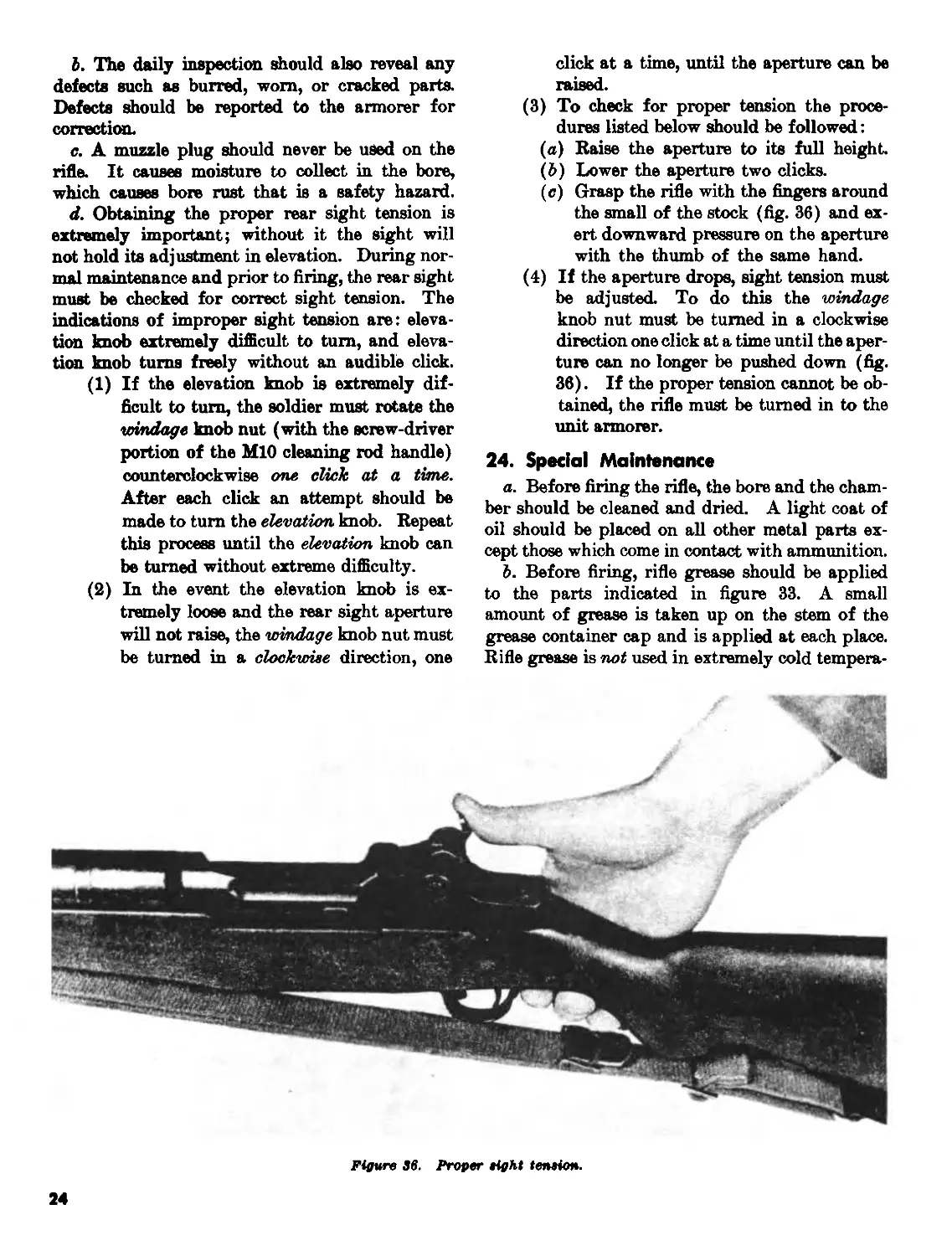
(3) To check for proper tension the proce-
dures listed below should be followed:
(a) Raise the aperture to its full height.
(&) Lower the aperture two clicks.
(c) Grasp the rifle with the fingers around
the small of the stock (fig. 36) and ex-
ert downward pressure on the aperture
with the thumb of the same hand.
(4) If the aperture drops, sight tension must
be adjusted. To do this the windage
knob nut must be turned in a clockwise
direction one click at a time until the aper-
ture can no longer be pushed down (fig.
36). If the proper tension cannot be ob-
tained, the rifle must be turned in to the
unit armorer.
24. Special Maintenance
a. Before firing the rifle, the bore and the cham-
ber should be cleaned and dried. A light coat of
oil should be placed on all other metal parts ex-
cept those which come in contact with ammunition.
Ъ. Before firing, rifle grease should be applied
to the parts indicated in figure 33. A small
amount of grease is taken up on the stem of the
grease container cap and is applied at each place.
Rifle grease is not used in extremely cold tempera-
Figwre 36. Proper sight tension.
24
tures or when the rifle is exposed to extremes of
sand and dust.
c. In cold climates (temperatures below freez-
ing) the rifle must be kept free of moisture and
excess oil. Moisture and excess oil on the working
parts cause them to operate sluggishly or fail com-
pletely. The rifle must be disassembled and wiped
with a clean, dry cloth. Drycleaning solvent may
be used if necessary to remove oil or grease. Parts
that show signs of wear may be wiped with a patch
lightly dampened with lubricating oil (LAW).
It is best to keep the rifle as close as possible to
outside temperatures at all times to prevent the
collection of moisture which occurs when cold
metal comes in contact with warm air. When the
rifle is brought into a warm room, it should not be
cleaned until it has reached room temperature.
d. In hot, humid climates or if exposed to salt
water or salt-water atmosphere, the rifle must be
inspected thoroughly each day for signs of mois-
ture and rust. It should be kept lightly oiled with
special preservative lubricating oil. Raw linseed
oil should be applied frequently to the wooden
parts to prevent swelling.
e. In hot, dry climates the rifle must be cleaned
daily or more often to remove sand and/or dust
from the bore and working parts. In sandy areas,
the rifle should be kept dry. The muzzle and re-
ceiver should be kept covered during sand and dust
storms. Wooden parts must be kept oiled with
raw linseed oil to prevent drying. The rifle should
be lightly oiled when sandy or dusty conditions
decrease.
f. Special instructions on caring for the rifle
when it is subject to nuclear, biological, or chem-
ical contamination can be found in TM 3-220 and
FM 21-40.
25
CHAPTER 6
AMMUNITION
25. General
The Ml rifle fires several types of ammunition.
The rifleman should be able to recognize them and
know which type is best for certain targets.
26. Description
The types of ammunition are identified by their
individual markings.
a. Batt, М2. This cartridge is used against
personnel and unarmored targets, and can be iden-
tified by its unpainted bullet.
Ъ. Armor Piercing, М2. This cartridge is used
against lightly armored vehicles, protective shel-
ters, and personnel, and can be identified by its
black bullet tip.
c. Armor Piercing Incendiary, МЦ.. This car-
tridge is used, in place of the armor piercing
round, against flammable targets. The tip of the
bullet is colored with aluminum paint.
d. Incendiary, Ml. This cartridge is used
against unarmored, flammable targets. The tip
of the bullet is painted blue.
e. Tracers and M25. These cartridges are for
use in observing fire, signaling, target designation,
and incendiary purposes. The tips of the bullets
are painted red for the Ml and orange for the
M25.
f. Blank, M1909. This cartridge is used to
simulate rifle fire. The cartridge is identified
by having no bullet, and by a cannelure in the
neck of the case which is sealed by red lacquer.
g. Rifle Grenade Cartridge, М3. This cart-
ridge is used with the grenade launcher to propel
grenades. The cartridge has no bullet and the
mouth is crimped.
h. Dummy, Mlfi. This cartridge is used for
marksmanship training. The cartridge case has
six longitudinal corrugations and the primer has
been removed.
i. Match, M72. This cartridge, used in marks-
manship competition firing, can be identified by
the word “MATCH” on the head stamp.
26
APPENDIX I
REFERENCES
FM 21-5
FM 21-6
FM 21-40
FM 23-71
TM 3-220
TM 9-1900
DA Pam 108-1
Military Training.
Technique of Military Instruction.
Small Unit Procedures in Chemical, Biological, and Radiological (CBR) Operations.
Rifle Marksmanship.
Chemical, Biological, and Radiological (CBR) Decontamination.
Ammunition, General.
Index of Army Motion Pictures, Filmstrips, Slides, and Phono-Recordings.
By Order of the Secretary of the Army:
Official:
J. C. LAMBERT,
Major General, United States Army,
The Adjutant General.
HAROLD K. JOHNSON,
General, United States Army,
Chief of Staff.
Distribution:
Active Army:
DCSPER (2) USAIB (5) Bde (3)
ACSI (2) U SCON ARC (5) Regt/Gp/Bg (1)
DCSLOG (2) USAODC (5) CO (2)
ACSFOR (2) USAMC (5) Bn (2)
CORO (2) OS Maj Comd (5) Co/Btry (1)
CNGB (5) LOGCOMD (1) USATC (5)
CRD (1) Armies (5) Br Svc Sch (1) except
COA (1) CINFO (1) TIG (1) Corps (3) Div (10) Div Arty (1) USAOC&S (3)
NO: State AG (3) ; Units—same as Active Army except allowance is two (2) copies to each unit.
USAR: Units—same as Active Army except allowance is one copy to each unit.
For explanation of abbreviations used, see AR 320-50.
For sale by the Superintendent of Documents, U.S. Government Printing Office
Washington, D.C., 20402 - Price 25 cents
* U.S. GOVERNMENT PRINTING OFFICE ; IMS О—771-M2
27