/


Tags: weapons military affairs

Text
RESTRICTED Security Information
TECHNICAL MANUAL
FOR
RIFLE, U.S., TYPE 99, JAPANESE CAL. .30
RESTRICTED Security Information
Contents
General
Part ftiei Construction and Function
Chapter 1 Rifle
I Construction
▲ Barrel Group
В Receiver Group
C Bolt
D Magazine
X Stock Group
II Function of Breech Mechanism
Chapter 2 Accessories
Chapter 3 Bayonet and Accessories
Chapter 4 Ammunition
Chapter 5 Spare Parts
Part Two: Handling
Chapter 1 Disassembly and Asseidbly
I Normal Disasseably and Assembly
II Special Diseassembly and Assembly
Chapter 2 Precautions in Handling
Chapter 3 Packing
Part Three: Preservation
Chapter 1 Care
I Daily Care
II Care Before Firing
III Care After Firing
IV Care During Special Instances
Chapter 2 Storage
1
Chapter 3 Inspection
I General Inspection
▲ Care
В Assembly
C Function
D Damage
II Inspection Before and After Firing
III Inspection of Stared Rifles
1 Wfr
I Construction
A Barrel Group
1 The Inside of the barrel is divided into a rifled section, ohanber,
bolt face seat.
The rifled section consists of four right twist riflings whose land
surface is chrome plated. The chamber is shaped to fit the cartridge
and its rear portion is rounded to form a bolt face seat.
The bolt face seat aids in guiding the ammunition and has an extractor
groove on the right side. The outside surface of the rear end of bolt face
seat is threaded. After the receiver is screwed on to the barrel, it is
aligned with the marker,
2 The barrel attachments consist of rear sight and rear sight base, front
sight and front sight base.
3 The rear sight base is mounted on the rear of the barrel and is pre-
vented from moving by a small rear sight base screw and a small rear sight
spring screw.
The rear sight leaf is pivoted by a rear sight joint pin and maintains
lowered and raised positions through rear sight spring action. The rear
sight leaf is graduated from 300 to 1500 meters by etched lines spaced into
2
100 meter units. Both sides of the rear sight leaf are notched at the above-
mentioned intervals to engage the rear sight slide catch when the upper edge
of the slide coincides with the previously mentioned etched lines. The
circular peep sight farmed at the bottom by loitering the rear sight leaf
is used for firing at ranges of 100 meters. The semicircular peep sight
formed by raising the rear sight leaf and slide is used far firing ranges
of 200 meters.
The forward edge of the rear sight leaf spring Is dovetailed and fits
into the rear sight base. It is held in place by set screws. The projec-
tion on the upper surface prevents the rear sight leaf from moving to the
right or left. The spring is curved upward so that it constantly exerts
upward pressure on the lower end of the rear right leaf.
The slide is inserted onto the rear sight leaf and is held in the
desired position by means of a spring loaded catch. The rear sight set
screw on the upper right side prevents the slide from slipping off. The
spring loaded slide catch is screwed on each side of the slide by a slide
pin. The center peep sight is aligned with the front sight for firing ranges
of 300 to 1500 meters. The catch of the slide through the action of the
spring engages the grooves on both sides of the real* sight leaf and holds
the slide in its various elevated positions. Oh each side and at the back
of the slide is an antiaircraft lead sight arm. The antiaircraft lead
sight arm has two scaled notches, 2 and 3> at the bottom. Notch 2 la used
for firing on aircraft traveling direct horizontal distances for 600 yards
at speeds of 125 miles per hour and Notch 3, at speeds of 185 miles per
hour. The antiaircraft lead sight arm is attached by antiaircraft lead
arm screws. The spring attached to the bottom holds the antiaircraft arm
In folded and extended positions. During its operation the aircraft is
aligned with the font and rear sight and fired upon when it enters the
3
proper notch on the bottom of the antiaircraft lead eight arm.
4 The front sight blade is dovetailed tightly into the front sight base.
The front sight base is attached to the forward end of the barrel and held
in position by the front sight base pin which ia inserted from left to right.
The line formed with the front sight base and the front sight is determined
by sero-ins. Two shoulders which project upward from the front sight base
serve as guards for the sight blade.
В Receiver Group
5 The receiver houses the bolt. The upper surface of the receiver has
two gouged holes. The one which is cut out from the top to the right side
serves as a receiver port during loading and as an ejection port after firing.
The cartridge clip housing is formed by the rear section. The other hole
serves as a path for the bolt handle. It is slanted towards the front end
to facilitate the action of the bolt when it is nulled back.
There is a long narrow recess along waoh side of the receiver in which
the bolt rides. Serial number of the rifle and the nans of the manufactur-
ing firm are engraved balow the groove on the left side. A slot which engaget
the bolt retainer base, and lip of ball retainer, and an ejector groove are
found on the rear left side.
The sear pin seat is located to the rear of the rectangular opening at
the bottom. The safety lock hole ia located on the forward section of the
sear pin seat and firing pin catch hole in the rear section. The forward
and rear receiver lugs are drilled for long and short receiver screws. The
screws are used to attach the trigger guard to the receiver. The buffer and
recoil plate are attached to forward and rear lugs, respectively, and serve
to transmit recoil shock to the stock during firing.
Qq each side of the inner surface ia a longitudinal groove which per-
mits the riding of bolt locking lug and extractor. The forward portion of th<
4
groove la widened to house the holt locking lug. Cfa the top surface of this
housing is a gas port wliich permits gas to escape. An engraved crest is
located In the forward portion of the gas port, and an engraved figure
"Type 99", reading from left to right, is located to the rear of the gas
port. The front end of the inside groove is also widened to provide passage
for the holt retaining lug. at the rear of the receiver there is a groove
for the lug on the safety knob and another groove for the sear catch. A groove
on which the safety catch lug rides is located in the extended portion of
the receiver. This groove curves to the left and serves as a guide and lock
for the safety catch lug when the rifle is set in safety position.
6 Receiver attachments consist of bolt latch, ejector, sear, trigger,
and recoil plate.
7 The holt retaining latch assembly fits on the left rear side of the
receiver. The sear catch always projects out through the action of bolt re-
taining latch spring attached to the bolt retainer. It engages the bolt
retaining lug and limits the backward movement of the bolt. In order to
remove the bolt from the receiver, the bolt retaining latch is pulled out to
disengage the catch. The ejector is attached to the bolt retaining latch
assembly by the latch screw ard projects into the ejector groove of the
receiver by th$ action of ejector spring attached to the bolt retaining latch
spring.
Tihen the bolt is brought to the rear, the ejector riding on the ejector
groove strikes the bottom of the cartridge and throws the cartridge out to
the right. The cetch of the bolt retaining latch gives proper position to
the ejector when the bolt is removed.
6 The sear has a firing pin catch on the rear end and a safety lock on
the front end, and is attached to the sear pin eeat of the receiver by means
of the sear pin.
5
Tho trigger is attached to the sear with a trigger pin and forma a
large and snail wavelike knoll. The large knoll engages the lower surface
of the receiver and adjusts the projection of the firing pin catch within
the receiver. The catch on the front end engages the bottom of the sear
and sets the position of the trigger. The sear spring encircling the
safety lock, pivots around the sear pin and alwa ys holds the firing pin
catch in projected position within the receiver.
When the trigger is pulled to the first phase (when the trigger play
is taken up), the sear spring is forced, and the big knoll turns while
engaging the lower surface of the reciever. Simultaneously with the engaging
of the knoll with the lower surface of the receiver, the firing pin catch
is lowered to a certain extent. When the trigger is pulled to the second
phase (when the sear is engaged), the sear spring ia subjected to further
pressure, the firing pin catch is lowered further, and the safety lock is
placed in the safety lock groove of the receiver. Through such action of
the safety lock, safety action is created. In short, the opening of the
bolt handle is prevented during discharge and the pulling of the trigger is
prevented when the rifle is half cocked,
9 The recoil plate is attached to the rear of the receiver. The rear lug
the receiver is Inserted into the forward hole. It is connected to the
trigger guard by screwing the trigger guard screw into the threaded hole in
the rear end. Together with the buffer, it transmits recoil to the stock
during discharge. Furthermore, together with the trigger guard it strength-
ens the rifle grip.
C Bolt
10 The bolt consisting of the following parts is attached to the receiver»
Bolt housing, firing pin, firing pin spring, safety catch, extractor, and
bolt cover.
11 The bolt housing contains a firing pin chamber, forward portion of
6
which is recessed to limit the forward motion of the firing pin during firing.
The front end of its head is called the breech surface* The embanked
lug at the head functions together with the extractor until the cartridge ie
extracted. The luga on both sides of the head are called the bolt locking
catches and tbs lug to the rear of the left bolt locking lug is called the
bolt retaining lug. The narrow groove extending through the centers of
the groove connects with the firing pin cbadber and pernlts gas to escape
fro* the primer. The bolt retaining lug engages the bolt retainer and
limits the backward movement of the bolt. The elliptical hole midway be-
tween the bolt looking lugs and toward its rear perDtits the gas to escape
from the bolt housing and at the same time indicates the position for
assembling the extractor. The extractor collar which adjoins the bolt
retaining lug is attached to the extractor and permits natural turning.
Two shallow grooves one to the right front and one to the bottom front of
the bolt handle, are found on the bolt housing. The right front groove
is the slot for the safety lock during firing, and the bottom front is for
the safety lug during the backward movement of the bolt when t)ie sear
catch presses the sear down. Approximately one-half of the circumference
to the sear is cut off in fork shape. The elongated cut-off is called the
snail-shaped section and the shorter cut-off is celled the semicircular
section, The snail-shaped section, together with the turning of the bolt
housing serves to withdraw the firing pin as it engages the sear catch,
and its bottom portion becomes the slot for sear catch during firing. The
semicircular section becomes the slot for the sear catch when the firing
pin is withdrawn. A collar on the rear end of the bolt housing engages
the groove on the inside of the safety knob and holds the bolt housing and
the safety knob together.
A small projection at the rear of the bolt handle engages the notch
cut into the outside of the safety knob, and during safety, together with
7
the safety catch, prevents the bolt handle from opening.
The firing pin assembly, consisting of striker and the firing pin
spring operates in tthe firing pin chamber of the bolt housing. The right,
inside surface at the rear of the firing pin has a longitudinal groove
terminating at the square opening in its forward end. This opening is
connected to the long narrow opening on the upper surface. These grooves
and openings serve as passages for the projection on the safety knob shaft
during assembly and disassembly. Furthermore, the long narrow opeining
serves as a passage for the projection on the safety knob shaft during the
forward motion of the firing pir. and prevents the firing pin from turning
freely. The projecting portion at the rear of the firii'g pin is called
the sear catch. The sear catch engages the firing pin catch and compresses
the firing spring. The small circular port in the front is a gas escape.
13 The firing pin sprang housed in the firing pin spring chamber activates
the firing pin and maintains the position of the safety device.
1Д The safety knob connects with the bolt housing and the firing pin
and engages the safety device. The rear portion of the knob is knurled
with a small semicircular notch at the left side and safety knob lug at
the bottom. The safety knob lug fits into the groove at ths rear end of
the receiver and prevents the safety knob from turning.
’rthen the safety knob is locked by pressing the safety knob forward and
turning the safety knob lug to the left during cocked position of the bolt,
the right side of the notched section or. the outside of the safety knob
engages the small projection or. the rear of the bolt handle and prevents
the raising of the bolt handle. One-half of the Inner circumference has
a sheIf-like recess which engages the collar on the rear of the bolt housing
and causes it to function together with the firing pin spring.
8
The safety knob shaft is the principal element in the bolt assembly.
The projection on tha center of the shaft fits into the long narrow groove
and opening of the firing pin spring chamber and facilitates the asserbly
of the bolt. During assembly, together with the safety knob lug, it pre-
vents the firing pin from turning.
The safety device turns the firing pin to the right, engages the sear
catch to the 1ft sear slot of the receiver, and prevents connection between
the sear and firing pin.
15 Tho extractor is a flat piece under spring tension. Its tip engages
the rear end of cartridge and extracts it. The projected section to the
rear of the tip fits into the groove at the head of the bolt casing which
prevents it from slipping forward.
The hollowed portion on the back surface of the extractor engages tha
projected portion of the extractor collar and holds the extractor to the
bolt housing. When the bolt handle is opened, the extractor remains in
the right inside groove of the receiver without being affected by the turn-
ing of the bolt housing since the extractor collar turns freely.
16 Since the bolt cover is attached to the receiver by means of bent tips
on both sides, it covers the upper surface of the receiver and prevents
dust from entering the receiver.
D Vegazine
17 The magazine consists of magazine body, trigger guard and their
accessories. The body is box shaped and contains a follower and a magazine
spring. It is used for loading ammunition. The front and back of the
magazine are attached to the trigger guard to prevent it from slipping out
from the stock.
18 The trigger guard forms a seat for the magazine and serves as a shield
for the trigger and as re-enforceirant for the stock grip. It is attached
9
to the bottom of the stock with three email screws. The long mouth towards
the front holds the bottom end of the magazine. The floor plate catch housing
is located at the rear section of the long mouth.
The short screw hole for the receiver is located at the forward tip of the
trigger guard. The trigger guard screw hole and a rectangular bole are found
at the rear end and center, respectively. Thus, room for operation of
trigger is provided. The semicircular guard which protects the trigger fans
a small hole in the front end as a recess for the floor plate catch. A long
set screw hole for the receiver is located at the rear of the other end.
19 The trigger guard accessories consist of the follower, magazine spring,
floor plate, floor plate catch, trigger guard screws and the long and short
set screws for the receiver.
20 The follower is a long narrow plate, the top surface of which is angled.
It is contained in the magazine and together with the magazine spring, raises
the ammunition In the magazine upward. A clamp for holding the magazine
spring Is located in the front under side of the follower.
21 The magazine spring is an "K” shaped flat spring, the narrow end of which
is attached to the follower; the other end is connected to the floor plate.
It constantly exerts pressure to raise the ammunition in the magazine.
22 The front er.d of the floor plate is attached to the front end of the
trigger guard magazine opening by means of a pin. A small recess in the
center of the floor plate engages the floor plate catch and prevents it
from opening. A lip is provided on the back of the floor plate for inserting
one end of the magazine spring.
2? The floor plate catch is attached to the floor plate catch housing of
the trigger guard. It consists of the body, screw and spring. It is ’’J"
shaped and operated in the groove located in the forward end of the trigger
guard semicircular section and is attached to the trigger guard by a small
screw.
10
The bottom front section of tbe catch has a claw and the rear section
is inletted. A swell hole in the center of the body is used as a catch hook
for a tool when the floor plate catch can not be released by finger• An
elliptical hole on the top surface of the body together with a snail screw
controls the novawent of the floor plate catch.
The screw is Inserted into the elliptical opening on the top of the
floor plate catch and screwed cn to the trigger guard. The spring is fitted
into the with one end being supported by the rear er.d of the floor plate
catch housing. It constantly exerts forward pressure on the claw and prevents
the elaw from releasing the floor plate.
When the floor plate catch is pulled to the rear, pressure is applied to
the catch spring, and this disengages the catch from the floor plate, thereby
causing the floor plate to open.
24 The trigger guard screw passes through the screw sleeve attached to the
stock and connects the rear, end of the trigger guard to the rear end of tbe
recoil plate. It 1я the longest screw in the trigger guard group.
25 The long and short receiver screws pass through the screw sleeve attached
to the stock. The long screw connects the rear end of the semicircular per**
tion of the trigger guard to the rear projection below the receiver and tbe
short screw, the forward end of the trigger guard to the forward projection
below the receiver. The short screw is the shortest one in the trigger
guard group.
E Stock Group
26 The rifle stock is made of walnut and its entire surface is lacquered.
The rifle stock is used to hold the rifle in firing and as a weapon with
the bayonet. It is attached to the rifle by means of screws, upper band ard
lower band. From the standpoint of convenience, the stock is divided into
three sections; namely, the stock, grip, and butt.
The stock has a cleaning rod chamber and cleaning rod catch housing in
tho front and a magazine housing on the rear. The screw hole located at the
extreme front end of the stock is used for the upper hand olate. The holes
following are used for upper hand and lower band, respectively.
▲ small hole is provided at the rear right side for repair work, and
grooves are provided on both sides in order to facilitate holding when firing.
The front end is notched to fit the upper band plate and upper hand. Hater
drainage hole for the cleaning rod chamber is located at the front bottom
section of the magazine housing.
The trigger slot is found at the rear. A longitudinal groove which
accommodates the forward projection of the receiver is found in the upper
forward section of the stock. An aperture for the buffer is located at the
back end of this groove. Two vertical holes located in the groove which accom-
modates the front and roar projections of the receiver.
The lower band located in the center of the stock is attached by means
of the lower hand screw. Two narrow, long, and service holes for the cleaning
rod chamber are found in the rear, interior of the cleaning rod chamber. The
grip section facilitates gripping of the rifle during firing.
The butt is made from two materials held together by means of dovetail
Joints and is provided with butt sling swivel and butt plate. The forward
end of the butt is reinforced by a recoil plate and trigger guard. The rear
end of the butt is protected by tlie butt plate. A screw sleeve is inserted
into the hole located at the rear of the recoil plate.
27 The stock attachments consist of upper band plate, upper band, cleaning
rod catch, hand guard catch (short rifle only), lower band, buffer, butt sling
swivel, batt plate, hand guard, end cleaning rod.
9ft The upper band plate covers the front end of the stock and is attached
to tlw upper band by means of upper band plate screw. Its semicircular notch
supports tlie barrel.
12
29 The upper band together id.th the upper band plate covers the head of the
stock and compresses the barrel frot.*. the top. It Is fitted to the cleaning
rod catch base by means of two screws. The upper band plate is attached to
the upper band by inserting upper band plate screw from right to left through
the screw hole located in the forward section of the upper band. The bayonet
lug found on the lower portion of the upper band is used for attaching the
bayonet.
30 The cleaning rod catch consists of the ЬоЦу, spring and seat. A hole
for inserting the cleaning rod is made in the bo«V and the seat. The body
operates within the seat. The spring fitted in the spring slot, constantly
applies pressure to the cleaning rod catch and causes the hole cC the seat
and the hole of the body to lock. Thus the body engages the recess of the
cleaning rod and prevents the cleaning rod from slipping out. In order to
release the cleaning rod, the body is pressed inward to disengage the cleaning
rod from the body and the cleaning rod is pulled out.
31 The hand guard oatoh io attached to the stock of tie later band section
located on the forward end of the hand guard in such a way that it holds the
barrel from the bottom. lhe upper surface of the hand guard catch clamps
into the hand guard and together with the metal frame at the rear portion of
the hand guard prevents the rrovement of the hand jiard.
32 The lover band is attached to the central portion of the stock. It
tightens the hand guard and prevents noveoent of the barrel. It is attached
to the stock by means of the lower band screw.
The lower band consists of the body, swivel, screw, and monopod. The
shape of the lower band for rifles and short rifles is different.
Hie monopod consists of the body, mount, mount pin, spring, spring pin,
and nut. The beety is inserted into the mount and is engaged by mount pin
which connects the mount and the lower band. The spring which is attached by
13
spring pin and nub and from both sides, maintains the monopod in folded or
erect position. When the monopod is iblded, etc., the front end hooks
on to the upper band screw. The lowering of the monopod is prevented by
locking. The spring pin is inserted from the right side and locked from the
left side with a nut.
The swivel of the rifle is attached to the bottom of the lower band and
that of the short rifle to the left side of the lower band. It is used for
attaching the sling. The monopod can be bent conveniently according to the
nature of the terrain.
33 The buffer is an angular shaft inserted from right to left into the buffer
hole located in front of the magazine housing of the stock. It is locked on
the left side by means of a nut. It sustains the forward projection of the
receiver and together with the recoil plate transmits the recoil during fire
to the stock.
34 The butt sling assembly consists of the seat and swivel. The seat is at-
tached to the butt and the swivel to the seat. The butt swivel and lower band
swivel are used to attach the slin& fhe shape and position of the butt sling
assembly for rifle and short rifle differ. In the case of the rifle the butt
sling assembly is attached to the bottom of the butt by means of long and short
screws. In the case of short rifles it is attached to the left side of the
butt by two wood screws. Since the seat of the butt sling assembly for the
short rifle is elevated to limit the forward tripping of the swivel, the sling
can be easily adjusted for slinging while wearing a gas mask.
35 The butt plate is attached to the aid of the stock by means of long and
shcrt wood screws. It protects the butt aid strengthens the joint of the two
materials which forms the butt.
36 The shape of hand guard for rifle and short rifle differs.
The hand guard for ilfle consists of ths ЬоЦу and metal frame. It covers
the barrel from the top, prevents its movenent and protects the hand from
14
grasping the gun when the barrel is heated. Its forward edge is clamped by
the lower band and the groove on its bottom surface fits over the hand guard
catch. Its rear end, the inner surface of which is attached to a metal frame,
is inserted into the front end of the rear sight base. 'Ihe metal frame covers
ths barrel and together with the hand guard catch, prevents the hand guard
from moving.
The hand guard for the short rifle consists of the tody and metal frame.
It covers the barrel from the top and prevents it from moving and protects
the hand in grasping the rifle when the barrel is heated. Its rear end, the
inner surface of which is attached to a metal frame, is inserted into the front
end of the rear sight base. The natal frame covers the barrel from the top.
Its front aid is covered by the upper band which, together with the lower
band, prevents the hand guard from moving. The lower band is located about
three and one-half inches in front cf the rear sight base and holds the hand
guard and the stock together by means of a screw.
37 The cleaning rod is used for cleaning and stacking rifles. A male screw
is provided at the bottom end and a hole at the top end. When the occasion
arises, cleaning rod jag, swab, and auxiliary cleaning rod can be attached to
the male screw. A piece of wood cr cloth can be Inserted in the top hole to
facilitate cleaning.
II Function of the breech mechanism
Зв The relationship between the receiver and bolt during fire isi
(a) When the bolt is opened and five rounds contained in the cartridge clip
are loaded into the magazine located at the front of the receiver, the rounds
depress the follower and stack up three to the rigit and two to the left.
The rounds are raised upward by means of the magazine spring.
(b) When the bolt is pushed forward, the clip is released by the pressure
exerted at the bottom by the bolt. The uppermost round, pushed from the rear,
15
elides up the cartridge ranp located in front of the magazine port at the bottom
of the receiver and enters the chamber. At this instance the extractor engages
the rear groove of the cartridge in preparation for extraction.
(c) When the bolt is completely closed and the trigger pulled, the sear is
lowered, this disengaging it from the cocking lever. The compressed firing
pin spiing drives the firing pin forward until the firing pin strikes the primer
of the cartridge.
At this time the bo It handle will not open since the safety lock has
engaged Jthe: safety lock groove of the bolt. Furthermore, when the breech is not
closed properly, the trigger cannot be pulled since the safety lock will not
be in’lirie With the groove. Thus, a safety meansure is provided.
(d) 5When the-boIt handle is raised and the bolt is brought to the rear, the
ejector, by means of ejector springs, enters the ejector groove of the bolt
housing and ejects the cartridge, which has been extracted by the extractor.
When the bolt is puxled back fully, it is prevented from slipping out of the
receiver since the bolt catch engages the holt retaining lug.
(e) When the bolt is again brought forward, the next round is loaded, dis-
charged, and ejected in the sane manner as the previous round.
(f) When all of the rounds have been expended the follower catches the bolt
fo.ce and prevents its advance. This indicates to the firer that the magazine
is empty.
39 Safety can be maintained by the safety lode and safety knob. The function
of the safety lock has been explained in (c) of 38. The safety knob in opera-
tion prevents the bolt handle from opening and locks the trigger. In shert,
the safety knob is operated in the following manner. When the safety knob is
pressed forward, turned 45 degrees to the rlj^it, the safety knob catch enters
the curved groove in the rear of the receiver and locks the safety knob. When
this is done, the small projection at the rear of the bolt handle engages the
recess on the outer fringe of the safety knob and prevents the bolt handle
16
and bolt from opening. At the sane time the firing pin turns with the safety
knob, the sear catch moves from the firing pin catch, enters the left recess
and disengages the firing pin from the sear, thereby locking the trigger.
When the safety knob is locked, the position of the semicircular cut on
the rear upper left of the safety knob is changed to an upward position.
Chapter 2 Accessories
AO Accessories include the following:
1. Accessories bag
Contents
Lubricating cord
Swab and
swab container
Cleaning rod tip
Auxiliary cleaning rod
Cleaning rod guide
Cleaning rod
2. Sling (Different for long rifle and shcrt rifle)
3. Ammunition pouch, Type A
Front ammunition pouch
Rear ammunition pouch rt-n
4. Anxnunition pouch, Type 3 inti
5. Ammunition pouch, type 0
6. Cartridge belt
7. Oil container, Type A, 2 1/2 ounces ,
8. Oil container, Type В (0.03 liter) 1 1/4 ounces
9. Anmiunition pouch, type A, B, anc 2; cartridge belt; oil container, tyjje A
(2 1/2 ounces); oil container, type 8(1 1/4 ounces) are used according
to respective maintenance classifications.
17
The accessorise bag is made of canvas, is ten Inches long and two and
one-eighth inches wide. It is opened and dosed by asms of a buckle type
strap and contains the following:
(1) Lubricating cord
This is used to clean the bore when time allows diring marches or
combat. It consists of a heap cord and weight with an over-all length of one
meter. When using, drop the weighted end into the bore, attach cleaning patch
to loop on opposite end and pull through to clean or lubricate bore.
(2) Cleaning rod tip
This consists of the body and the cleaning rod tip spindle which is
screwed onto the cleaning rod or the auxiliary cleaning rod. The bore is
cleaned by wrapping a cleaning patch aroind the body which rotates.
(3) Swab
This is made of brass, equipped with a brush (hog bristles), and a
connecting tube with a femaxe screw at the lower end. It is attached to the
cleaning rod or the auxiliary cleaning rod and used in cleaning the bore.
When not in use it is always kept in the metal swab container to protect the
brush.
(4) u Cleaning rod
Made of brass, it is used to clean the bolt, receiver, and other‘grooves.
The;mole serves in attaching cleaning patches.
(5) Auxiliary cleaning rod
There are two rods; one with a female screw, and the other with a male
screw. The female screw joins into the cleaning rod and the male screw into
the cleaning rod tip or swab. When cleaning, the auxiliary rod is attached.
(6) Cleaning rod glide
Made of cylindrical wood with a catch toward the rear. When cleaning,
this is attached to the Receiver and the cleaning rod thrust through it to
18
prevent defacing of the bore. The catch fits into the bolt handle slot located
toward the rear of the receiver and prevents movement of the cleaning rod guide.
42 The gun sling is attached to the swivel, located on the lower band and
the outt, by means of the snap fastener, buckle, and loose strap. The length
can be adjusted by means of the buckle. The sling for the short rifle differs
in that it is wider, 25-mm shorter, and equipped with a snap link at the lower
end which, together with the butt swivel assembly, makes demounting of the
sling convenient.
43 Ammunition pouch, Type A is the general nomenclature for two fxvnt am-
munition pouches and one rear ammunition pouch. The front pouches consist of
the body, belt loop, button, connecting strap, cover, fastening loop, and
cover fastener. The rear ammunition pouch consists of the body, fastening
loop, button (with seat), belt loop, cover, cover fastener, partition and
fastening straps Type A and B. T^e belt loop is attached to the bayonet belt.
The interior of each ammunition pouch is partitioned into two compartments
which hold the aaxrunition wrapped in a paper container. The rear anminitinn
pouch is equipped with an exterior compartirent for oil container Type A
(2 1/2 ounces). There are two elliptical holes in the bottom to facilitate
removal of the paper containers.
44 Amounltion pouch Туре В consists of the body, belt loop, cover fastener
button, fastening strap, buckle strap, button, cover, cover fastener strap,
partition, fastening loop, and the belt. The partition divides the interior
into three compartments. The middle coapartm^nt holds oil container туре В
(1 1/4 ounces) and the side compartments hold the ammunition wrapped in a
paper container. It is equipped with an exterior compartment which holds the
cleaning rod and cleaning rod tip. It is slung over the left shculder by
means of the listening strap (buckle strap, button) and fastened around the
waist by means of the belt.
19
45 ’Amnunltion pouch type C is amnunltion pouch type В without the belt and
tightening strap (buckle strap, button).
46 The cartridge belt is made of canvas and reinforced on top and bottom by
leather. It is fastened around the waist by means of the buckle strap and
tightening strap. It has large, medium, and small pouches. There are two
large pouches which hold one hand grenade each, six medium pouches which hold
ten rounos of amnunltion each, and one small pouch vhich holds an oil container.
47 Oil container type A consists of the body, applicator, cases A and B,
and screw cap. Oil container type В consists of the boty, applicator, filling
spout, and cases A and 3.
Chapter 3
Bayonet and Accessories
43 The bayonet and other steel parts are all blued. It consists of the
blade (hilt, pommel, guard, hilt grip, catch) and scabbard. The blade is
straight with a groove on each side and an over-all length of 20 inches.
The hilt has a guard toward the blade end and the pommel riveted to it
at the butt end. The bayonet lug groove is on the pommel which also houses
the catch. The bayonet lug on the rifle fits into the bayonet lug groove and
the action of the catch unites the rifle and the bayonet. The catch which is
equipped with a spring is inserted into the catch housing from the light and
fixed in place from the jeft by means of an escutcheon. The escutcheon is center
punched. The end of the guard with the round hole is known as the "dragon's
head" and when the bayonet is fixed the other end is Known as the "dragon's
tail". The easily handled hilt grip is attached on both sides of the hilt
by means of two sets of screws, seat, and escutcheon with the forward end
adjoining the guard and the other end adjoining the pommel. The screws are
inserted from the right and seated with the escutcheon from the left. The
blade stem is 7 1/2 inches in length from the forward end.
20
The ecabbard consists of a mouth, scabbard catch, md a pointed tip. The
mouth reinforces the upper end of the scabbard. A plate spring is welded
below this. The scabbard catch ie attached below the mouth by «mans of a
screw. The bayonet is fastened to the frog by means of the scabbard strap on
the frog. The pointed tip is welded and protects the tip of the scabbard.
The plate spring which is located within the scabbard sandwiches the blade
and prevents it from slipping out.
49 Bayonet accessories include the frog and the belt. The bayonet is attached
to the frog and the belt which suspends the frog is used to carry the bayonet
as a sidearm.
The frog is equipped with a buckle and a scabbard strap. The belt is
equipped with a buckle and strap. In the event the belt is too short for the
user, there is the long belt Type A (B).
Chapter 4 Anmunltion
50 The regular cartridge, Ball cal. .30, М2, consists of the cartridge case,
primer, proptllent powder and the bullet. Its over-all weight is 396 grains
and its over-all length is 3*34 inches. The case is made of brass. Bullet
tip is plain and unmarked. The bullet is composed of a gilding metal and
a lead core.
51 Cartridge Armor Piercing, cal. .30, М2. This cartridge is similar in
appearance to the cartridge, Ball cal. .30, М2 except that the bullet tip is
black. The bullet consists of a gliding metal jacket, a hard alloy steel
core, a lead 11T" shot point filler and a gilding metal base filler.
52 Cartridge tracer cal. .30 K-I. This cartridge is used in rifles for
signal and incendiary purposes, target designation, range estimation and target
practice. This cartridge is readily identified by the red bullet tip
21
Indicating the color of the trace.
53 Cartridge tracer cal. .30 M25 (T-10). Thia cartridge ia used in machine
guns primarily but may be used in rifles also.
The difference between this cartridge and the cartridge tracer cal. .30,
Ml is that the bullet from this cartridge has a dim trace up to approximately
100 yards, then the bri^it trace begins aid continues to approximately 1,000
yards. The color of the bullet tip is orange.
54 Cartridge blank cal. .30 M19O9. This cartridge is used for simulated fire
in maneuvers and exercises, signaling purposes and firing salutes. It is readi-
ly identified since it has no bullet.
55 Cartridge dummy cal. .30, М2. This cartridge is used lor training per-
sonnel in the operation of loading and unloading rifles and simulating rifle
fire and in the inspection of weapons. It is easily identified by the three
holes drilled in the cartridge caso and the absence of a primer.
56 Cartridge, Rifle Grenade, cal. .30, М3. This cartridge is loaded with
five grain a of black powder and forty grains of smokeless powder. This cart-
ridge ia used only with standard ilfla grenades md grenade projection adapters.
Length of cartridge is 2.49 inches. The cartridge may be readily identified
by the characteristic "Sn petal rose criop of the moith.
Part Two: Handling:
Chapter I Disassembly and Assembly
57 There are two types of dieassembly, regular and special. However, the
special dieassembly shall be limited to repairs and other necessary instances
performed by Ordnance personnel and the basic principle shall be that it ie
not conducted in general. Also the users of arms and schools are prohibited
disassemblies other than those mentioned in thia chapter. Except in specially
mentioned cases, the assembly shall generally be conducted in the reverse order
to that of the disassembly.
22
Ав far as the disassembly end assembly are concerned, the following
must be noted carefully and any defective parts of the rifle must be
repaired immediately.
1 Normal disassembly and assemoly
58 Parts that can be disassembled by the using unit.
Regular disassemblies are:
sling
bolt
cleaning rod
follower spring and the follower
The assembly and disassembly of the sling are as follows:
(1) In order to disassemble the rifle sling,
(a) Unfasten the link catch and break the connection with the
upper band.
(b) Lower the strap.
(c) Unfasten the buckle.
(d) When the end of the sling is unfastened from the strap;
(e) The sling becomes detached from the butt.
(2) In order to assemble the rifle sling,
(a) Slip the sling through the buckle.
(b) The sling is slipped through so that the stitches of the
strap are on the left side of the rifle.
(c) Pass the «id of the sling from the rear through the butt
sling swivel.
(d) Pass the strap through.
(e) Pass the «id of the sling through the buckle from the front
side.
(f) Fasten at the appropriate eyelet.
23
(g) Place the end of the sling into the strap.
(h) Push the strap up until it is below the buckle.
(i) Connect the front end of the sling with the lower band
swivel.
(3) Disassembly of the short rifle sling.
(a) Unfasten the link button and detach from the lower band.
(b) The removal of the buckle, strap and the spring catch are
the same as with the rifle.
(c) In the very end, the spring catch is detached from the butt
sling swivel.
(4) Assembly of the shcrt rifle sling.
(a) Fit the buckle.
(b) Insert the strap.
(c) Fit the spring catch so that the open and close section
faces the stock.
(d) After this, the steps are the same as with the rifle.
60 In order to detach the bolt, place the rifle in a horizontal position
with the barrel facing up; while supporting the rifle with ths left hand
grasp the bolt handle with the right hand and place in an upright position
pull it completely backward, then open the bolt catch to the left with
the left thumb, and pull the bolt handle slowly backward to remove from
the receiver.
61 The bolt is disassembled in the following order after the bolt
cover is first removed.
(1) Safety knob
Hold the bolt with the left hand and place the palm of the rigit
hand on the rear of the safety knob. Exert sufficient pressure on this,
and turn completely to the rL£it then if the pressure is released the
24
safety knob will become detached from the bolt housing.
(2) Firing pin
Remove from the bolt housing
(3) Firing pin spring.
Remove from the striker
(4) Extractor
Grasp the bolt housing with the left hand. After moving the
position of the extractor to above the elliptical hole, press the ex-
tractor forward and detach.
(5) Precautions should be exercised in the following cases in
the disassembly aid assembly of the bolt.
(a) When removing the bolt, care should be taken so that the
butt will not be damaged by the safety knob lug.
(b) In assemblying the extractor, align the extractor collar
ears with the elliptical hole of the bolt housing, fit the hole on the
bottom surface of the extractor, and with the left hand grasp the bolt
body together with the spring portion of the extractor, then press the
extractor outward <th the right thumb and push into place vhich connects
it with the extractor collar. After assembly, turn the extractor to the
left and engage the projection behind the extractor hooks into the groove
of the extractor housing then place it accurately over the light lock-
ing lug of the bolt.
(c) In inserting the fixing pin into the bolt housing, the
sear lug oust be fitted into the rear semicircle, otherwise it will
be impossible to assemble the bolt.
(d) In fitting the safety knob, the lug in the middle of the
25
axle is fitted into the narrow groove on the inside of the rear part
of the filing pin, thm pressure is exerted. If it does not enter even
after application of pressure, turn slightly to left or rigit so that
proper contact is made. After the safety knob enters, turn it completely
to the left then relieve the pressure.
(e) If the sear lug of the firing pin is fitted by mistake
into the snail-shaped portion at the rear of the bolt housing, grasp
the bolt housing with the left hand, press the safety knob sufficiently
with the rigit hand and turn the sear lug to the rigit along the snail-
shaped part. After it stops, reapply pressure and when the firing pin
spring will move no further, the sear lug is fitted into the semicircular
part. Then the safety knob is rotated to the left. It is now correctly
assembled.
(f) If through error the bolt is placed into the receiver
without assemblying the extractor, without forcing anything, first
ascertain the position of the safety knob lug. Then after guiding
it correctly to the right, extract the bolt slowly. When the ex-
tractor is being detached because of jamming during fire, alter the
extractor collar is moved to the light side, the bolt is pushed for-
ward carefully and the extractor is engaged with the extractor collar.
Then the bolt is puxled о ack. Also when the empty cartridge case
remains in the cartridge chamber due to jamming, a clean cleaning rod
is inserted into the bore and the cartridge ejected before engaging
the ejector.
(g) When the bolt is fitted into the receiver, the correct-
ness of the bolt assembly is rechecked, the catches on both sides of
the bolt covers are fitted into the grooves on the outside of the
26
receiver, the bolt retainer is opened outward, the bolt pushed forward,
magazine platform depressed downward and assembly completed. Then the
trigger is pulled and the firing pin is left in the sear catch position.
62 In removing-the cleaning rod, place the rifle in a vertical position
with the barrel facing frontward. With the left hand grasp below the
cleaning rod catch and press the catch with the thumb. Then lift cut
the cleaning rod.
63 In removing the follower spring and the follower, pull the floor
plate catch. After the floor plate opens, grasp it with the left hand.
With the right hand grasp the lower blade of the spring slightly above
the bent portion, lift upward slightly and pull backward. Then it will
become detached from the floor plate. The follower and the follower
spring are also disassembled in the same manner.
II Special disassembly and assembly, (Цу Ordnance personnel only)
64 Special disassembly is ex&uted after the regular disassembly are;
Front upper band and the upper band plate.
Lower band.
Hand guard
Barrel and receiver (base maintenance only)
Magazine
Floor plate catch
Cleaning rod catch
Hutt plate
Butt sling swivel
27
Monopod
6$ The order of the special disassembly is as follows:
(a) Front sigit base and front sight.
After the сад Iked pin is extracted from xl£ht to left, tue seat
is tipped forward. The sight can be pounded out either from the left
or ri,$t. Care oust be exercised not to damage the front sight blade.
When reassembled it oust be zeroed-in again, the old marker line erased
and replaced by a new marker line.
(b) Upper band and the upper band plate
Remove the left and right screws and the plate bolt, and detach
with the plate.
(c) Lower band
Place the barrel facing left, unscrew the small screw and remove
together id th the monopod.
(d) Hand guard
Barrel is placed facing upward. Grasp the front end of the hand
rail and remove together with the metal frame by pulling slowly to the
front while slightly lifting upward.
(e) Barrel and receiver
After removing the long and short receiver screws and the trigger
guard screw, place the rifle in a level position with the barrel facing
up, grasp the receiver with the right hand and the front sight section
with the left hand, then remove upward. Next detach the recoil plate.
In order to disassemble the rear sight, the rear axle pin is
removed and the rear sight detached. The rear sight spring is dis-
assembled from the base ty removing the small rear sight spring screw
and tipping it lightly forward. In the disassembly of the slide,
28
first remove the small rear sight screw and detach the slide from
the rear si git. Next, unscrew the left and rijgit slide catch pins
then detach the slide catches and slide catch springs from the slide.
In the disassembly of the antiaircraft lead sight arms, the antiair-
craft lead sight arm screws are unscrewed and the arms removed. The
springs are next detached. The spring will become detached if pulled
about ttree millimeters from the outside inward.
In the disassembly of the rear sight base, the rear sight base
screw is removed and the base pulled out to the fore. In the dis-
assembly of the bolt retainer and the ejector, after pulling out the bolt
retainer spring, unscrew the bolt retainer pin. Then detach the bolt
retainer from the receiver and the ejector from bolt retainer. The
ejector spring is inserted in the bolt retainer latch spring. In
disassemblying the sear and the trigger, the sear pin is extracted,
then the sear and the trigger are detached from the receiver. Next,
the trigger pin is removed and the trigger detached from the sear.
(f) Magazine
In the disassembly of the magazine, the trigger guard is detached
from the stock, the front pin extracted, and the floor plate removed
from the trigger guard. Then the magazine can be readily disassembled
as it is merely inserted into the magazine chamber in the stock.
When assemblying the magazine, place the lower side toward the
front and tne angular side facing up.
29
(g) Floor plate catch
The floor plate catch is disassembled by removing a small screw
to the rear of the trigger guard, then pulling it out together with
the spri ng.
(h) Cleaning rod catch
The cleaning rod catch is removed by pushing it inward from the
outside. In such cases the base and the spring of the cleaning rod
catch disassembles together from the stock.
(i) Butt plate
The butt plate is disassembled by unscrewing the wood screws.
When as se mb lying the longer wood screw is screwed in at the lower
end and the shorter wood screw is screwed in at the top,
(j) Butt sling swivel
The bubt sling swivel is disassembled by removing the wood
screws. With the rifle, the longer wood screw is screwed in on the
side that is closer to the front end and the shorter wood screw on
the side that is closer to the rear end. With the short rifle the
slanted surface is placed facing the rear end. Be sure that error
is not made as to the front and the rear sides.
(k) Monopod
The monopod is disassembled from the lower band, the spring
pin aid nut are removed then the spring detached, the monopod
base pin is removed then the monopod base is detached from the
lower band, and the momopod from the momopod base.
66 Care must be exercised in the special disassembly and
assembly of the following cases.
(a) During the disassembly and assembly of the upper and
lower oands, the bluing of the barrel must not be scraped off and*
the stock must not oe damaged.
30
(Ъ) During the disassembly of the hand guard, care mist be taken in
order not to damage the metai frame and the rear end.
(c) When removing the barrel and receiver, the front and the rear must
be removed evenly from the stock, otherwise the stock may be damaged.
(d) The barrel and the receiver are disassembled only when replacement
of the barrel is necessary.
(e) When the trigger giard screws and the receiver screws are being
screwed in, be sure thqf are turned evenly, otherwise the trigger guard may
become tilted and cannot be properly tightened; also when the small screw is
not tightened properly, it affects the accuracy of the rifle. When firing,
the contact point between the stock aid the receiver is often damaged when the
barrel recoils.
(f) During assembly, the pins and screws must be inserted in the direc-
tion stipulated.
Chapter 2 Precautions in Handling.
67 The point to be noted in the tests mentioned below is that the easily
damaged parts must be handled with care. Although the other details are
identical to those described in the manual on preservation of arms, the main
points are:
68 The muzzle, front sight, rear si^it, and the bolt oust not be allowed
to touch the ground.
69 When the rifle is not in use the bolt is closed and the firing pin is
placed in the after-fire position.
The use of wood, paper, cloth, etc., as a cap for the muzzle must be
avoided because of the possibility of damage to the barrel.
70 The ammunition is first loaded into the magazine and then inserted into
the chamber by the bolt. Whai the ammunition is placed directly in the chamber
and the bolt closed the extractor will be damaged.
31
71 After exposure to dust, the bore, conditions permitting, should be cleaned
before firing, The muzzle section should be spot checked.
72 When exposed to га-in or snow the bore oust be cleaned as soon as time
permits. The presence cf moisture in the Interior cf the rifle promotes
rusting.
73 Tbe plugging of the muzzle with vaseline or grease in order to prevent
the entry of water into the bore must be avoided because if fired while plugged,
it mqy cause the barrel to bulge or burst.
74 If the monopod is bent during use, it is corrected ty the soldier him-
self if possible.
75 Precautions that should be taken in subzero areas.
(a) If misfires occur frequently, wipe the oil from the bolt assembly.
(b) Whan keeping the rifle incbors after use, proper oil must be applied
to it. The sling must be kept away from fires, and it is also necessary to
take precautions against freezing as the leather sling cracks easily.
(c)' During the period&the rifle is not in use, it muat be kept, in a
warm place or indoors as much as possible to prevent it from freezing. If
kept Outdoors unavoidably, it must be covered with a blanket or a straw mat.
If possible a fire should be built indoors to prevent ary trouble when called
upon for unexpected firing.
(1) When a rifle is carried in from out of doors, the change of tem-
perature induces moisture to form on the metallic parts causing it to rust.
Therefore, it oust be wiped off: the bore especially must be cleaned.
(2) The humidity of buildings in subzero areas equipped with heaters
becomes exceedingly low and unless the stock is oiled, it will become excessive-
ly dry. As this causes the stock to warp, the rifle rack must be placed in
a position as far as possible from the heater, and humidity must be maintained
at the proper level.
32
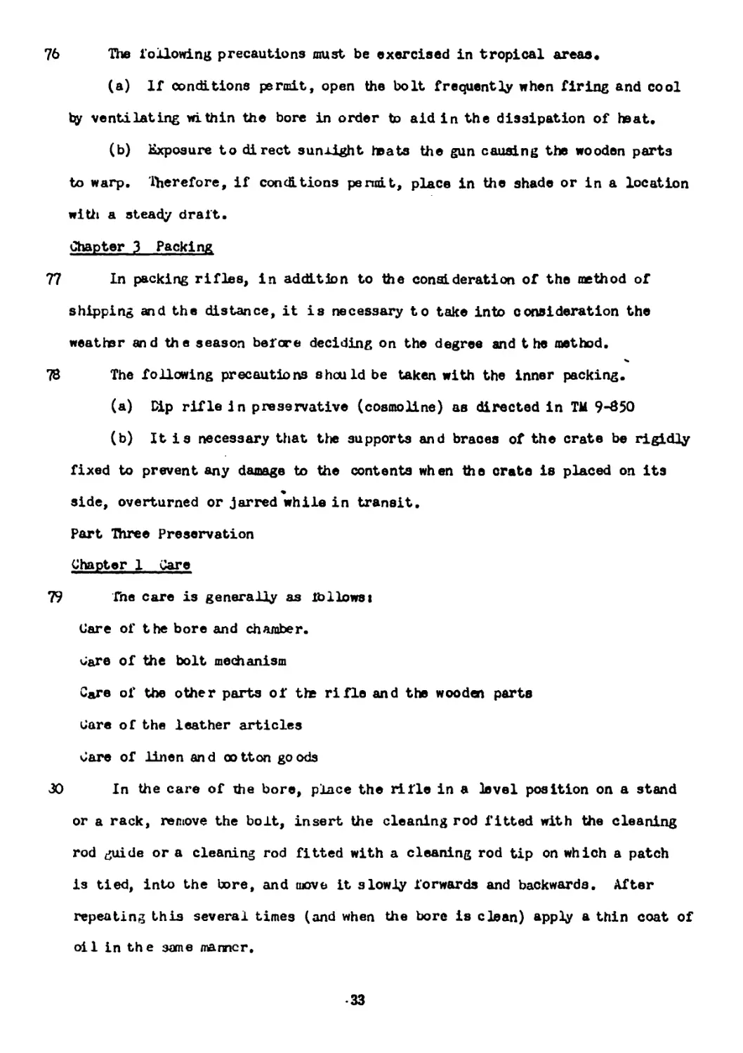
7b The following precautions must be exercised in tropical areas*
(a) If conditions permit, open the bolt frequently when firing and cool
by ventilating within the bore in order to aid in the dissipation of heat.
(b) Exposure to direct sunlight teats the gun causing the wooden parts
to warp. Therefore, if conditions penult, place in the shade or in a location
with a steady draft.
Chapter 3 Packing
77 In packing rifles, in addition to the consideration of the method of
shipping and the distance, it is necessary to take into consideration the
weatter and the season before deciding on the degree and the method.
78 The following precautions should be taken with the inner packing.
(a) Dip rifle in preservative (cosmoline) as directed in TM 9-850
(b) It is necessary that the supports and braces of the crate be rigidly
fixed to prevent any damage to the contents when the crate is placed on its
side, overturned or jarred while in transit.
Part Three Preservation
Chapter 1 Care
79 The care is generally as ibllowsi
Care of the bore and chamber.
dare of the bolt mechanism
C&re of the other parts of the rifle and the wooden parts
Gare of the leather articles
Care of linen and cotton goods
30 In the care of The bore, place the rifle in a level position on a stand
or a rack, remove the bolt, insert the cleaning rod fitted with the cleaning
rod guide or a cleaning rod fitted with a cleaning rod tip on which a patch
is tied, into the bore, and move it slowly forwards and backwards. After
repeating this several times (and when the bore is clean) apply a thin coat of
oil in the sane manner.
33
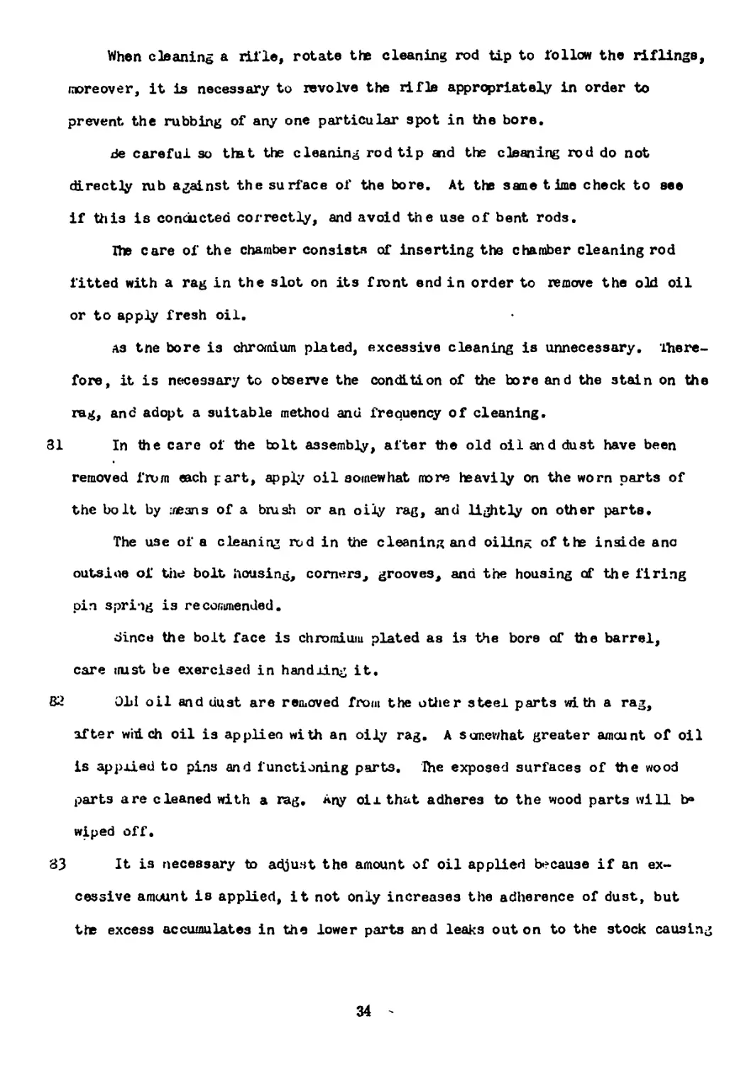
When cleaning a rifle, rotate the cleaning rod tip to follow the riflings,
moreover, it is necessary to revolve the rifle appropriately in order to
prevent the rubbing of any one particular spot in the bore.
tie careful so that the cleaning rod tip and the cleaning rod do not
directly zub against the surface of the bore. At the same time check to see
if this is conducted correctly, and avoid the use of bent rods.
Ihe care of the chamber consists of inserting the chamber cleaning rod
fitted with a rag in the slot on its front end in order to remove the old oil
or to apply fresh oil.
as tne bore is chromium plated, excessive cleaning is unnecessary. There-
fore, it is necessary to observe the condition of the bore and the stain on the
rag, and adopt a suitable method and frequency of cleaning.
31 In the care of the bolt assembly, after the old oil and dust have been
removed frum each part, apply oil somewhat more heavily on the worn parts of
the bolt by means of a brush or an oily rag, and lightly on other parts.
The use of a cleaning rod in the cleaning and oiling of the inside ano
outs ice of tile bolt housing, corners, grooves, and the housing of the firing
pin spring is recommended.
dince the bolt face is chromium plated as is the bore of the barrel,
care irust be exercised in handling it.
32 Old oil and dust are removed from the other steel parts wi th a rag,
after which oil is applieo with an oily rag. A somewhat greater amount of oil
is applied to pins and functioning parts, Hie exposed surfaces of the wood
parts are cleaned with a rag. Any oil that adheres to the wood parts will b®
wiped off.
83 It is necessary to adjust the amount of oil applied because if an ex-
cessive amount is applied, it not only increases the adherence of dust, but
the excess accumulates in the lower parts and leaks out on to the stock causing
34
it to become stained; moreover, it may be blown into the eyes of the gunner
when firing.
84 Leather goods are cared for by applying a thin film of Neats Foot Oil
on the top surface with a piece of rag. Apply sparingly, then wipe off the
excess with a dry cloth.
When applying oix to the leather s lin& it must be rubbed crosswise
and not lengthwise.
Any oil remaining on textile fabric products oust be removed as it
damages the fibers.
If any mildew is detected, clean immediately with either a dry or a moist
cloth, however, when this anthod is not adequate, care must be exercised
because it frequently promotes further growth; moreover, a rag once used to
remove mildew must not be used on other unaffected leather parts.
85 Soiled web canvas products are washed in soapy water.
86 Lven during fire, the rifle is cleaned and cared for as conditions permit.
Il Care Before Firing
87 Ja^e before fire consists of a thorough cleaning of the bore and the
chamber followed by an application of a thin film of oil. мп application of
an excessive amoutn of oil becomes a hindrance. When firing blank ammunition
a somewhat greater am cunt of oil should be applied.
Ill Care After Firing
83 As the quality of the after-fire care greatly influences the preservation
of the rifle, it is necessary to exercise special care. In ad-iition to the
general daily care the following care must be rendered.
(a) h'hen exposed to gas, wash the contaminated parts as soon as possible
with the bore cleaning fluid or a soapy solution using a swab, or clean with
bore oil.
(b) After removing the contaminant and dirt with a rag, apply oil.
35
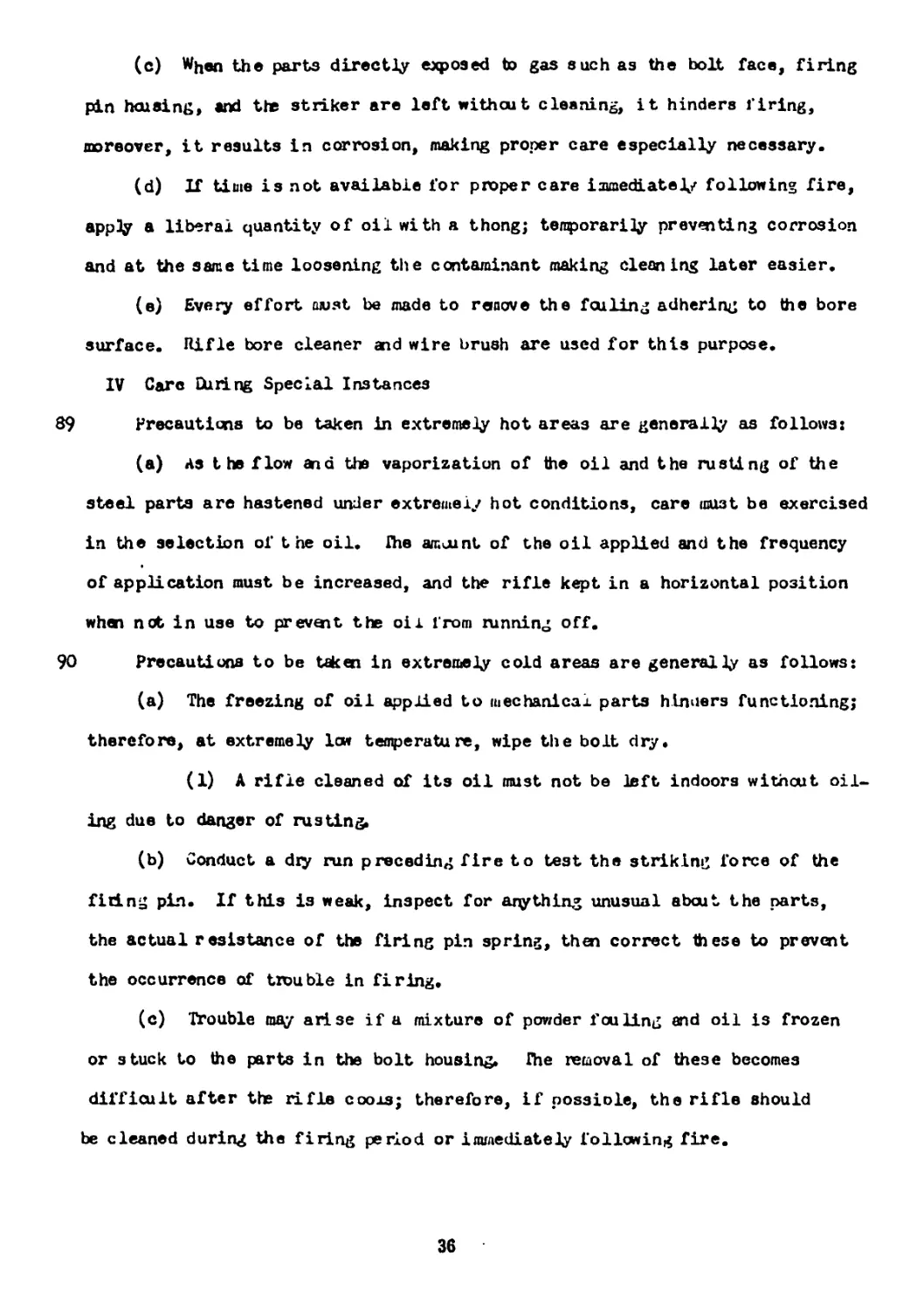
(c) W^en the parts directly exposed to gas such as the bolt face, firing
pin housing, «nd the striker are left without cleaning, it hinders firing,
moreover, it results in corrosion, making proper care especially necessary.
(d) If time is not available for proper care immediately following fire,
apply a liberal quantity of oil with a thong; temporarily preventing corrosion
and at the same time loosening the contaminant making clean ing later easier.
(e) Every effort must be made to remove the fouling adhering to the bore
surface. Rifle bore cleaner and wire brush are used for this purpose.
IV Care During Special Instances
89 Precautions to be taken in extremely hot areas are generally as follows:
(a) As t he flow and the vaporization of the oil and the rusting of the
steel parts are hastened under extremely hot conditions, care must be exercised
in the selection of the oil. Ihe amount of the oil applied and the frequency
of application must be increased, and the rifle kept in a horizontal position
whan net in use to prevent the oix from running off.
90 Precautions to be taken in extremely cold areas are generally as follows:
(a) The freezing of oil applied to tuechanicax parts hinuers functioning;
therefore, at extremely lew temperature, wipe the bolt dry.
(1) A rifle cleaned of its oil must not be left indoors without oil-
ing due to danger of rusting.
(b) Conduct a dry run preceding fire to test the striking force of the
firing pin. If this is weak, inspect for anything unusual about the parts,
the actual resistance of the firing pin spring, then correct these to prevent
the occurrence of trouble in firing.
(c) Trouble may arise if a mixture of powder fouling and oil is frozen
or stuck to the parts in the bolt housing, fhe removal of these becomes
difficult after the rifle cooxs; therefore, if possiole, the rifle should
be cleaned during the firing period or immediately following fire.
36
71 Precautions to be taken when the dust is severe:
(a) In order to prevent adhesion and penetration of dust, application
of oix to external parts must be minimized.
(b) When the possibility of sand penetration is great, the bore must be
cleaned frequently with an oiieu cloth, tied loosely to the cleaning rod.
The cloth must be changed often. The bore must be oiled only after it is ab-
solutely free of sand. If the daily cleaning procedure is used from the start,
the possibility of damage and wear to the bore is great since it would be
like ruboing the bore with polishing powder. When the bore is being cleaned
fraii the muzzle end, special care in cleaning must be directed to the cart-
ridge chamber since the sand from tlie bore will accumulate in the cartridge
chamber.
92 Precautions to be taken during rain and snow.
(a) in rain and snow, oiling iaist be done only after the moisture has been
completely wiped off with a dry cloth. This operation must be conducted re-
peatedly.
Chapter 2 Storage
93 The purpose of storing arms is to take appropriate measures to preserve
them for long or short periods in order that they may be used again without
any breakdown. The method of storage and the handling of stored goods pre-
sent cec in Technical Manual 9~3>O U. 5. Arjy will be followed.
Chapter 3 Inspection
I • Jenera 1 inspection
A Care
94 Principal points of Inspection
(a) Barrel
(1) Foreign matter (a) rust, pits anti corrosion,
(2) Metal Fouling adhesion.
37
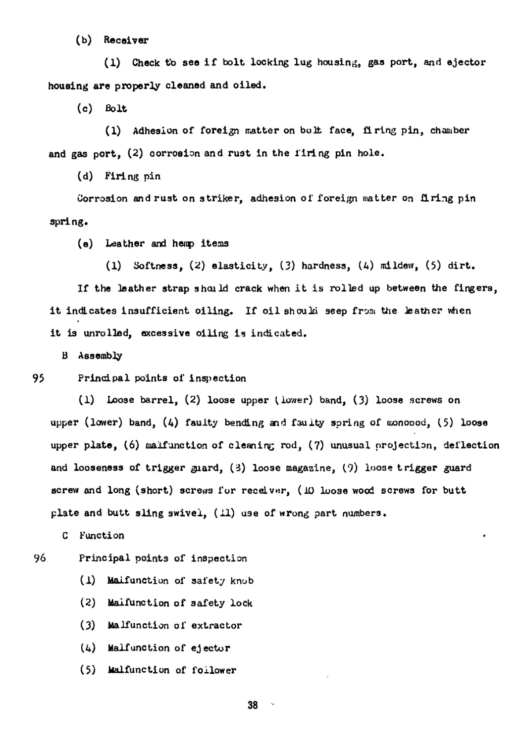
(b) Receiver
(1) Check tb see if bolt locking lug housing, gas port, and ejector
housing are properly cleaned and oiled.
(c) Bolt
(1) Adhesion of foreign matter on bolt face, firing pin, chamber
and gas port, (2) corrosion and rust in the firing pin hole.
(d) Firing pin
Corrosion and rust on striker, adhesion of foreign matter on firing pin
spring.
(e) Leather and heap items
(1) Softness, (2) elasticity, (3) hardness, (4) mildew, (5) dirt.
If the leather strap should crack when it is rolled up between the fingers,
it indicates insufficient oiling. If oil should seep from the leather when
it is unrolled, excessive oiling is indicated.
В Assembly
95 Principal points of inspection
(1) Loose barrel, (2) loose upper Slower) band, (3) loose screws on
upper (lower) band, (4) faulty bending and faulty spring of monoood, (5) loose
upper plate, (6) malfunction of cleaning rod, (7) unusual projection, deflection
and looseness of trigger ^iard, (3) loose magazine, (9) loose trigger guard
screw and long (short) screws for receiver, (10 Loose wood screws for butt
plate and butt sling swivel, (U) use of wrong part numbers,
C Function
96 Principal points of inspection
(1) Malfunction of safety knob
(2) Malfunction of safety lock
(3) Malfunction of extractor
(4) Malfunction of ejector
(5) Malfunction of follower
38
(6) thru (1Д) Faulty trigger mechanism
(15) Faulty function of bayonet in mounting and dismounting.
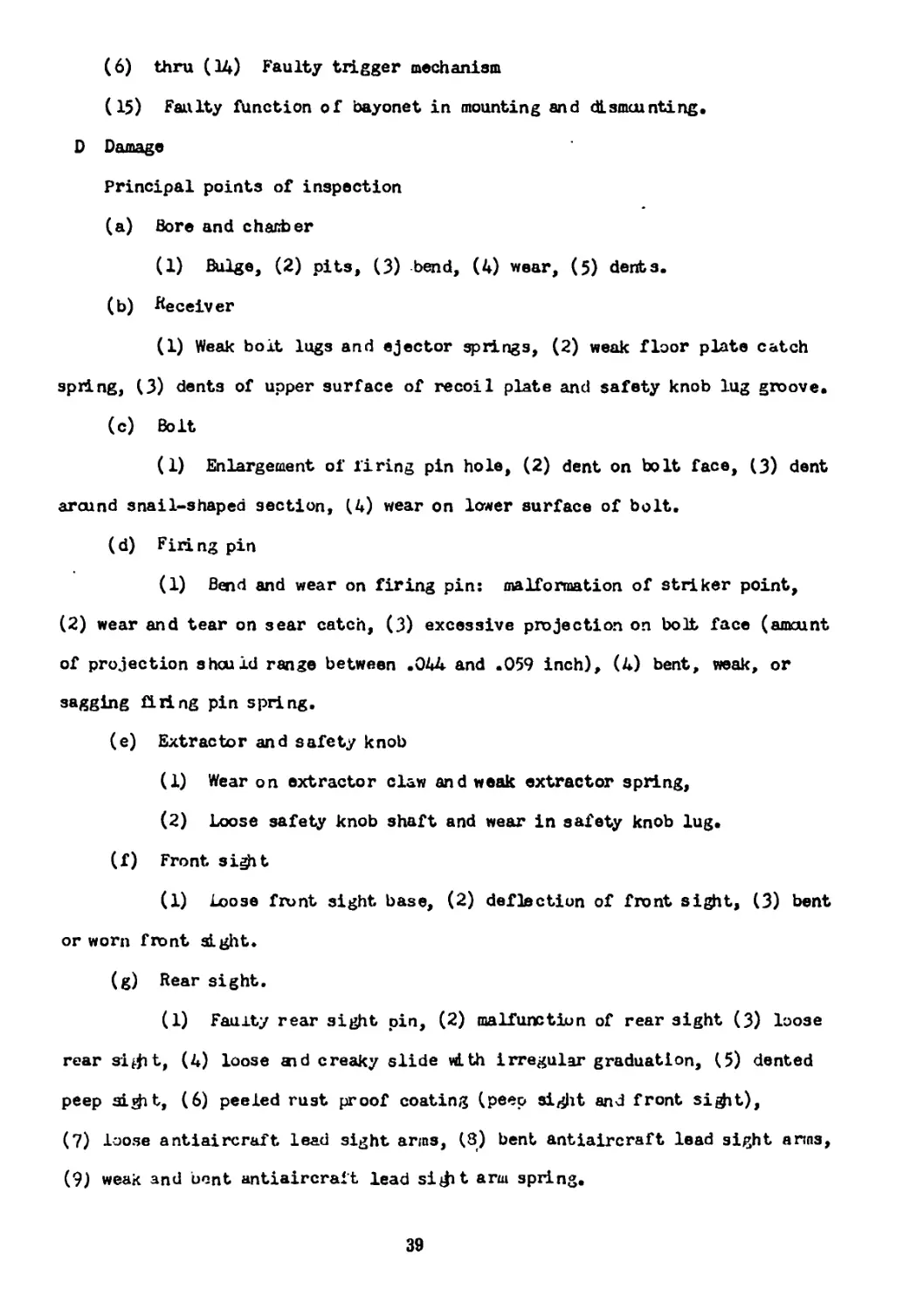
D Damage
Principal points of inspection
(a) Bore and chamber
(1) Bulge, (2) pits, (3) bend, (4) wear, (5) dents.
(b) Receiver
(1) Weak bolt lugs and ejector springs, (2) weak floor plate catch
spring, (3) dents of upper surface of recoil plate and safety knob lug groove.
(c) Bolt
(1) Enlargement of firing pin hole, (2) dent on bolt face, (3) dent
around snail-shaped section, (4) wear on lower surface of bolt.
(d) Firing pin
(1) Bend and wear on firing pin: malformation of striker point,
(2) wear and tear on sear catch, (3) excessive projection on bolt face (amount
of projection should range between .044 and .059 inch), (4) bent, weak, or
sagging firing pin spring.
(e) Extractor and safety knob
(1) Wear on extractor claw and weak extractor spring,
(2) Loose safety knob shaft and wear in safety knob lug.
(f) Front sight
(1) Loose front sight base, (2) deflection of front sight, (3) bent
or worn front si gilt.
(g) Rear sight.
(1) Faulty rear sight pin, (2) malfunction of rear sight (3) loose
rear si^it, (4) loose aid creaky slide with irregular graduation, (5) dented
peep si^it, (6) peeled rust proof coating (peep sight and front si^it),
(7) loose antiaircraft lead sight arms, (3) bent antiaircraft lead sight arms,
(9) weak and bent antiaircraft lead si^t arm spring.
39
(h) Stock
(1) Cracked and dented stock, (2) enlarged groove fbr recoil plate
(1/32 inch allowed), (3) bent stodt, (4) cracked and loose hand guard, (5)
bent cleaning rod, loose cleaning rod head, aid worn thread, (6) broken snap
ring lor sling.
(i) Leather aid hemp items
(1) Cracks, (2) scars and damages, (3) unraveled seams.
(j) Accessories
(1) Crooked and bent cleaning rod jag, worn threads and corroded
steel section, (2) bent and worn cleaning rod, (3) damages to screw cap for
oix can, weak oil can case, and oil can leaks.
II Inspection Before and After Fixing
98 Before and after firing, various parts, especially the bore, and chamber,
Special inspection must be made for the presence of foreign natter in the bore
and chanter before firing.
Prior to zeroing-in, damaged parts whidi will al feet the accuracy of
seroing-in oust be carefully noted, inspected and, if necessary, repaired.
When large amounts of gas leaks from the rear during firing, inspection
fcr irregularities oust be nade on the changer, bolt face, bolt locking lug,
firing pin head, extractor, and bolt retaining lug housing.
Ill Inspection of Stored ^ifles
99 Prior to storage, special attention must be paid to the presence of rust,
matching of part numbers, proper function, and proper application of preserva-
tive. dore and chamber must be examined with special thoroughness.
40
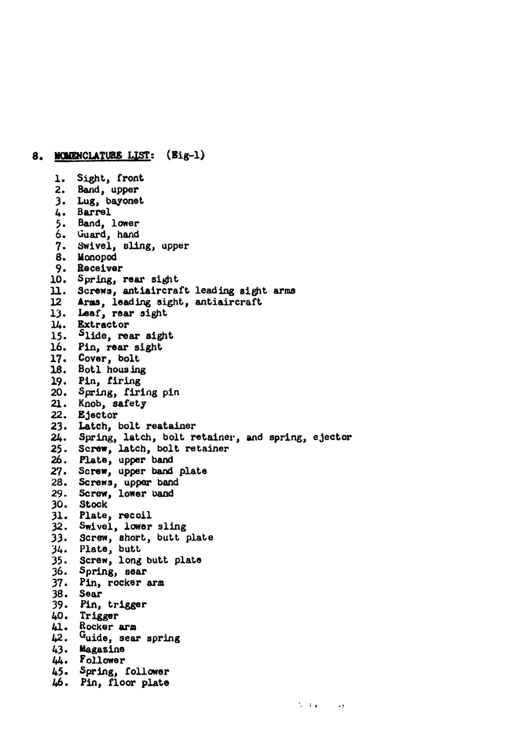
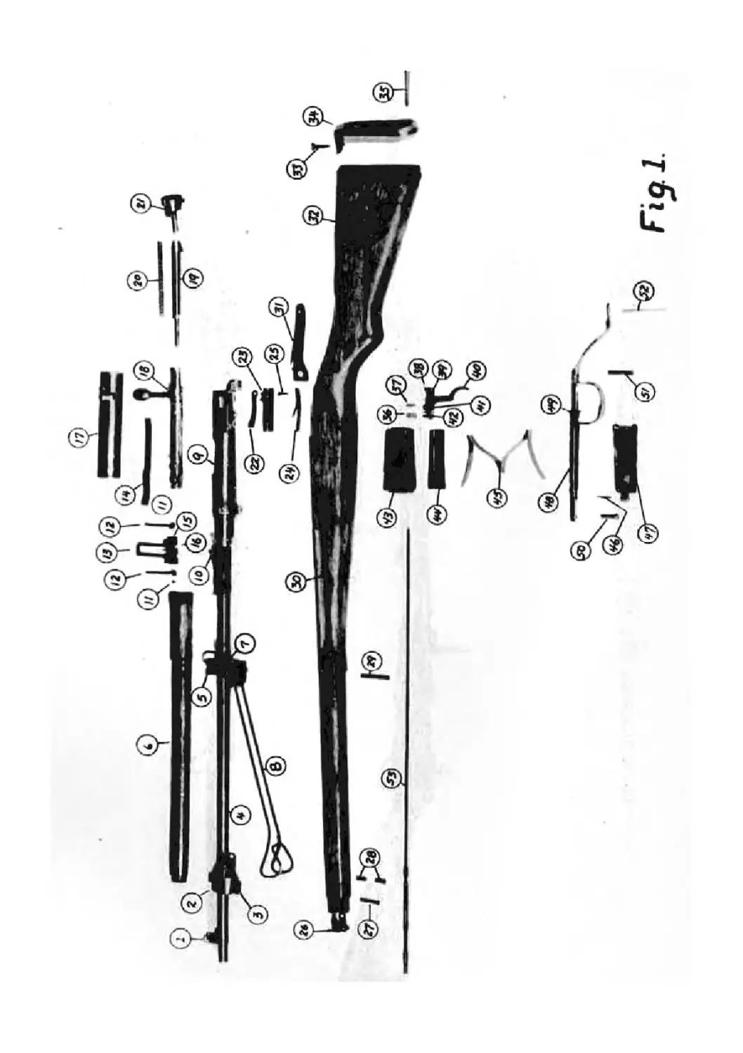
8. MfiUEMfilATllHK LIST; (Big-1)
1. Sight, front
2. Band, upper
3. Lug, bayonet
4. Barrel
5. Band, lower
6. Guard, hand
7- Swivel, sling, upper
8. Monopod
9. Receiver
10. Spring, rear sight
11. Screws, antiaircraft leading sight arms
12 Aras, leading sight, antiaircraft
13. Leaf, rear sight
14. Extractor
15. slide, rear sight
16. Pin, rear sight
17. Cover, bolt
18. Botl housing
19. Pin, firing
20. Spring, firing pin
21. Knob, safety
22. Ejector
23» Latch, bolt reatainer
24. Spring, latch, bolt retainer, and spring, ejector
25• Screw, latch, bolt retainer
26. Plate, upper band
27 > Screw, upper band plate
28. Screws, upper band
29. Screw, lower band
30. Stock
31. Plate, recoil
32. Swivel, lower sling
33. Screw, short, butt plate
34. Plate, butt
35. Screw, long butt plate
36. Spring, sear
37. Pin, rocker arm
38. Sear
39. Pin, trigger
40. Trigger
41. Rocker arm
42. ^uide, sear spring
43* Magazine
44. Follower
45- Spring, follower
46. Pin, floor plate
NOMENCLATURE LIST (Fig. 1) Cont'd
47. Plate, floor
48. Guard, trigger
49. Catch, floor plate
50. Screw, forward, trigger guard
51. Screw, rear, trigger guard
52. Screw, recoil plate
53. 8od, cleaning
I
TOP