/
Tags: weapons military affairs
Year: 1965


Text
FM 23-8
DEPARTMENT OF THE ARMY FIELD MANUAL
U.S. RIFLE
7.62MM, M14 AND M14E2
HEADQUARTERS, DEPARTMENT OF THE ARMY
MAY 1965
♦FM 23-8
Field Manual
No. 23-8
HEADQUARTERS
DEPARTMENT OF THE ARMY
Washington, D.C., 7 May 1965
U.S. RIFLE
7.62MM, M14 AND M14E2
Chapter 1. INTRODUCTION Paragraph Page
Purpose and scope______________________________________ 1 2
Importance of mechanical training_______________________ 2 3
Description of the rifles_______________________________ 3 3
General data.________________________________________ 4 4
2. MECHANICAL TRAINING
General___________________________________________________ 5 6
Clearing the rifle.____________________________________ 6 6
Disassembly into three main groups______________________ 7 7
Assembly of the three main groups_______________________ 8 7
Disassembly of the barrel and receiver group____________ 9 9
Assembly of the barrel and receiver group______________ 10 10
Disassembly of the gas system and handguard------------ 11 13
Replacing the stabilizer assembly of the M14E2 rifle___ 12 13
Removing the stabilizer assembly of the M14E2 rifle- 13 14
Replacing the stabilizer assembly of the M14E2 rifle___ 14 14
Disassembly of the magazine____________________________ 15 14
Assembly of the magazine.............................. 16 14
3. OPERATION AND FUNCTIONING
Section I. Operation
Loading the magazine (out of the rifle)_________________________ 17 19
Loading the magazine (in the rifle)____________________ 18 19
Loading and unloading the rifle----------------------- 19 19
II. Functioning
Semiautomatic---------------------------------------- 20 19
Automatic (rifles equipped with selector)-------------- 21 26
Chapter 4. STOPPAGES AND IMMEDIATE ACTION
Stoppages...............................—---------------------- 22 28
Immediate action_______________________________________ 23 29
5. MAINTENANCE
General_______________________________________________ 24 30
Cleaning materials, lubricants, and equipment__________ 25 30
Cleaning the rifle.................................. 26 32
Normal maintenance___________________________________ 27 33
Special maintenance................................... 28 39
6. AMMUNITION
General._______________________________________________ 29 40
Description________________________________________ 30 40
Packaging__________________________________________ 31 40
Care, handling, and preservation._____________________ 32 40
7. ACCESSORIES
М2 bipod________________________________________________ 33 42
M6 bayonet knife and M8A1 bayonet knife scabbard____ 34 42
M76 grenade launcher................................ 35 42
M15 grenade launcher site........................... 36 42
M12 blank firing attachment and М3 breech shield_______ 37 45
Winter trigger kit.___________________________________ 38 48
Appendix. REFERENCES____________________________________________ .. 49
♦This manual supersedes FM 23—8, 7 December 1959, including С 1, 20 May 1960, and C 2, 15 August 1962.
1
CHAPTER 1
INTRODUCTION
1. Purpose and Scope
a. This manual is a guide for commanders and
instructors in presenting instruction in the me-
chanical operation of the M14 and M14E2 rifles.
It includes a detailed description of the rifle and
its general characteristics; procedures for detailed
disassembly and assembly; an explanation of func-
tioning; a discussion of the types of stoppages and
the immediate action applied to reduce them; a de-
scription of the ammunition; and instructions on
the care, cleaning, and handling of each weapon
and its ammunition.
Ъ. Marksmanship training is covered in FM 23-
71 and FM 23-16.
c. The material contained herein is applicable
without modification to both nuclear and nonnu-
clear warfare.
d. Users of this manual are encouraged to sub-
mit recommended changes or comments to improve
the publication. Comments should be keyed to
the specific page, paragraph, and line of the text
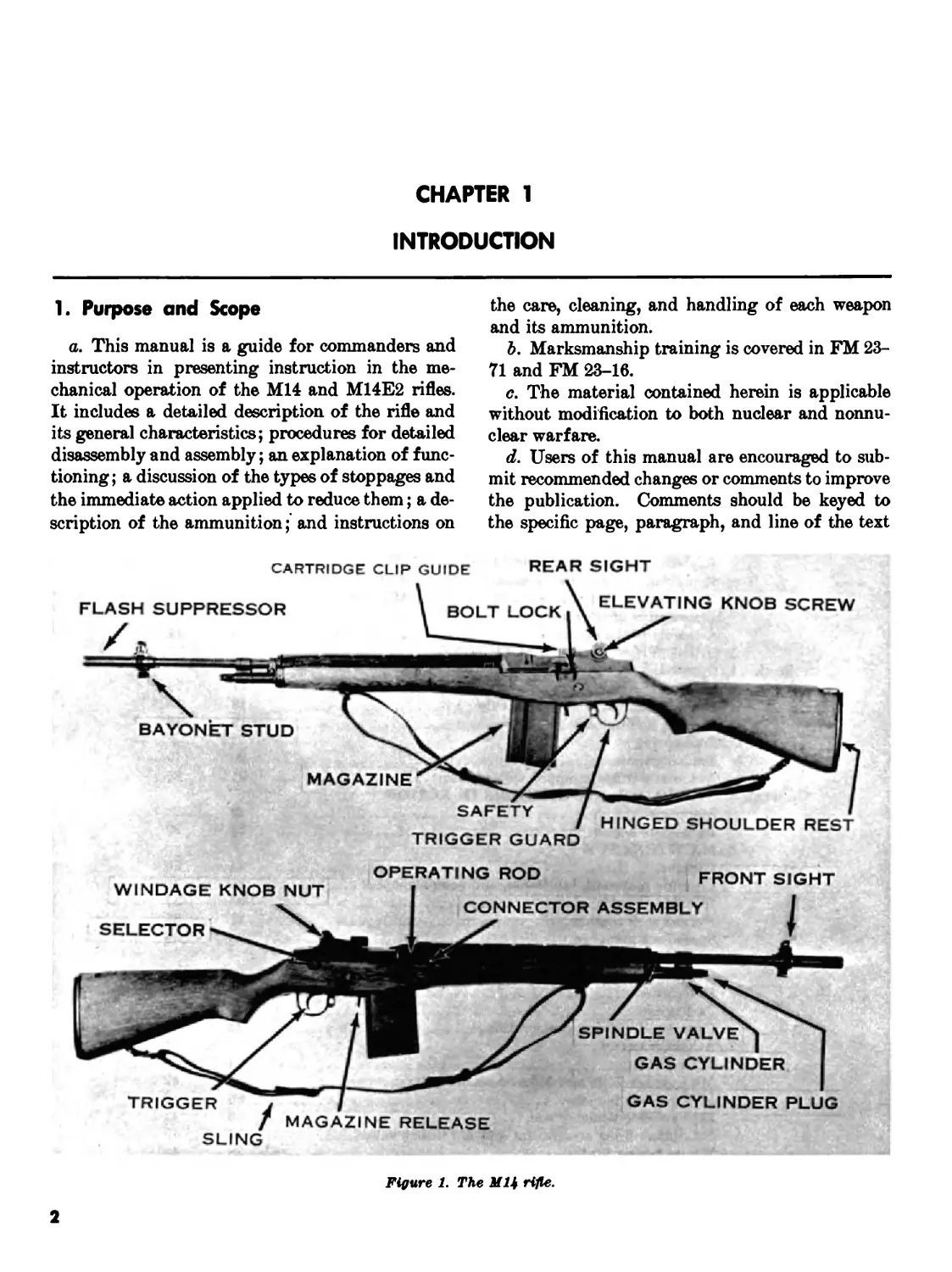
Figure 1. The МЦ rifle.
2
in which the change is recommended. Reasons
should be provided for each comment to insure un-
derstanding and complete evaluation. Comments
should be forwarded direct to the Commandant,
United States Army Infantry School, Fort Ben-
ning, Ga., 31905.
2. Importance of Mechanical Training
The rifle is the Infantryman’s basic weapon. It
gives him an individual and powerful capability
for combat. To benefit the most from this capa-
bility, the Infantryman must develop two skills to
an equal degree: he must be able to fire his weapon
well enough to get hits on battlefield targets, and
he must know enough about its working parts to
keep it operating. The Infantryman attains his
firing skill in marksmanship training. He learns
how to keep his rifle in operable condition through
mechanical training.
3. Description of the Rifles
a. Rifle.
(1) The U.S. rifle, 7.62mm, M14 (fig. 1) is
a light-weight, air-cooled, gas-operated,
magazine-fed, shoulder weapon. It is de-
signed primarily for semiautomatic fire.
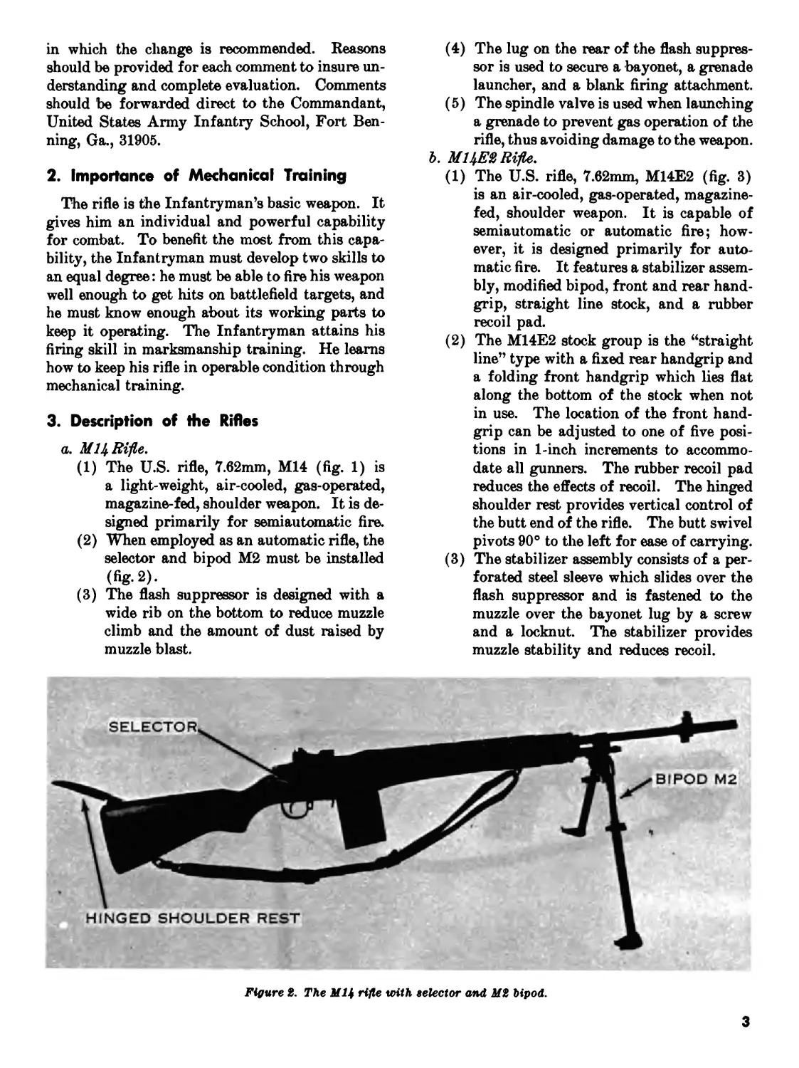
(2) When employed as an automatic rifle, the
selector and bipod М2 must be installed
(fig-2).
(3) The flash suppressor is designed with a
wide rib on the bottom to reduce muzzle
climb and the amount of dust raised by
muzzle blast.
(4) The lug on the rear of the flash suppres-
sor is used to secure a bayonet, a grenade
launcher, and a blank firing attachment.
(5) The spindle valve is used when launching
a grenade to prevent gas operation of the
rifle, thus avoiding damage to the weapon.
b. Ml Rifle.
(1) The U.S. rifle, 7.62mm, M14E2 (fig. 3)
is an air-cooled, gas-operated, magazine-
fed, shoulder weapon. It is capable of
semiautomatic or automatic fire; how-
ever, it is designed primarily for auto-
matic fire. It features a stabilizer assem-
bly, modified bipod, front and rear hand-
grip, straight line stock, and a rubber
recoil pad.
(2) The M14E2 stock group is the “straight
line” type with a fixed rear handgrip and
a folding front handgrip which lies flat
along the bottom of the stock when not
in use. The location of the front hand-
grip can be adjusted to one of five posi-
tions in 1-inch increments to accommo-
date all gunners. The rubber recoil pad
reduces the effects of recoil. The hinged
shoulder rest provides vertical control of
the butt end of the rifle. The butt swivel
pivots 90° to the left for ease of carrying.
(3) The stabilizer assembly consists of a per-
forated steel sleeve which slides over the
flash suppressor and is fastened to the
muzzle over the bayonet lug by a screw
and a locknut. The stabilizer provides
muzzle stability and reduces recoil.
Figure 2. The МЦ rifle with selector and М2 bipod.
3
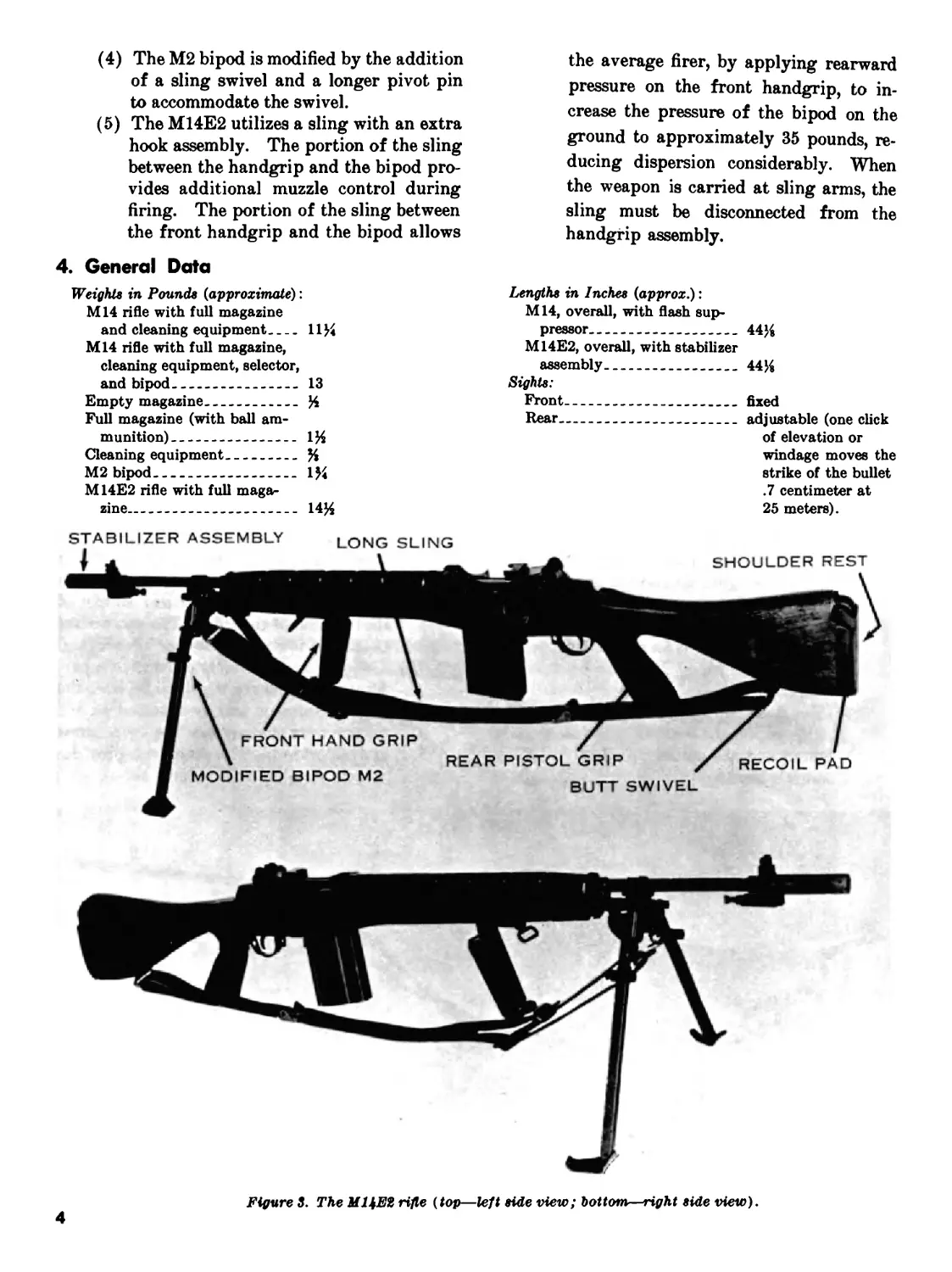
(4) The М2 bipod is modified by the addition of a sling swivel and a longer pivot pin to accommodate the swivel. (5) The M14E2 utilizes a sling with an extra hook assembly. The portion of the sling between the handgrip and the bipod pro- vides additional muzzle control during firing. The portion of the sling between the front handgrip and the bipod allows 4. General Data Weights in Pounds (approximate): M14 rifle with full magazine and cleaning equipment 11% M14 rifle with full magazine, cleaning equipment, selector, and bipod 13 Empty magazine % Full magazine (with ball am- munition) 1% Cleaning equipment % М2 bipod 1% M14E2 rifle with full maga- zine.. 14% STABILIZER ASSEMBLY LONG SLING 11 \ the average firer, by applying rearward pressure on the front handgrip, to in- crease the pressure of the bipod on the ground to approximately 35 pounds, re- ducing dispersion considerably. When the weapon is carried at sling arms, the sling must be disconnected from the handgrip assembly. Lengths in Inches (approx.): M14, overall, with flash sup- pressor 44% M14E2, overall, with stabilizer assembly 44% Sights: Front fixed Rear adjustable (one click of elevation or windage moves the strike of the bullet .7 centimeter at 25 meters). —_ SHOULDER REST
\ FRONT HAND GRIP MODIFIED BIPOD М2 REAR PISTOL GRIP X^^RECOIL PAD BUTT SWIVEL
Figure 3. The МЦЕ2 rifle (top—left side view; bottom—right side view).
4
Trigger Pull in Pounds: Minimum 5.5 Maximum 7.5 Muzzle Velocity 2,800 f.p.s. (853 m.p.s.). Cyclic Rate of Fire (rounds per 700-750 minute). Rates of Fire. (These can be maintained without danger to the firer, or damage to the weapon): Semiautomatic (rounds per minute): 1 minute. — 40 2 minutes 40 5 minutes 30 10 minutes 20 15 minutes 20 20 minutes 20 30 minutes (or more) . 15 Automatic (rounds per min- ute): 1 minute 00 2 minutes . 50 *The bipod adds much stability to the rifle and enables the automatic rifleman to effectively engage targets semlautomatically in excess of 460 meters. 5 minutes 40 10 minutes 30 15 minutes. 30 20 minutes 25 30 minutes (or more) 20 Range in Meters: Maximum effective (semiau- 460 tomatic, without bipod). Maximum effective (semiau- *700 tomatic, with bipod). Maximum effective (automa- **460 tic, with bipod). Maximum 3725 Ammunition see chapter 6. Definitions: Cyclic rate the rate at which the weapon fires auto- matically. Maximum effective range the greatest distance at which a weapon may be expected to fire accurately to inflict casualties or damage. ••Enemy squad formations and hasty crew-served weapons emplacements may be effectively engaged up to this range; bunker apertures, windows and like targets, which require precise accuracy, can best be engaged using semi- automatic fire.
5
CHAPTER 2
MECHANICAL TRAINING
5. General
a. The individual soldier is authorized to disas-
semble his rifle to the extent called field stripping.
Chart I shows the parts he is permitted to dis-
assemble with and without supervision. The
amount of disassembly he is permitted to perform
without supervision is adequate for normal main-
tenance.
b. The frequency of disassembly and assembly
should be kept to a minimum consistent with main-
tenance and instructional requirements. Constant
disassembly causes excessive wear of the parts and
leads to their early unserviceability and to inac-
curacy of the weapon.
c. The rifle has been designed to be taken apart
and put together easily. No force is needed if it
is disassembled and assembled correctly. The
parts of one rifle, except the bolt, may be inter-
changed with those of another when necessary.
Bolts should never be interchanged for safety
reasons.
d. As the rifle is disassembled, the parts should
be laid out from left to right, on a clean surface
and in the order of removal. This makes assembly
easier because the parts are assembled in the re-
verse order of disassembly. The names of the
parts (nomenclature) should be taught along with
disassembly and assembly to make further instruc-
tion on the rifle easier to understand.
6. Clearing the Rifle
The first step in handling any weapon is to clear
it. To clear the rifle, first attempt to engage the
safety. (If unable to place the safety in the safe
position, continue with the second step of remov-
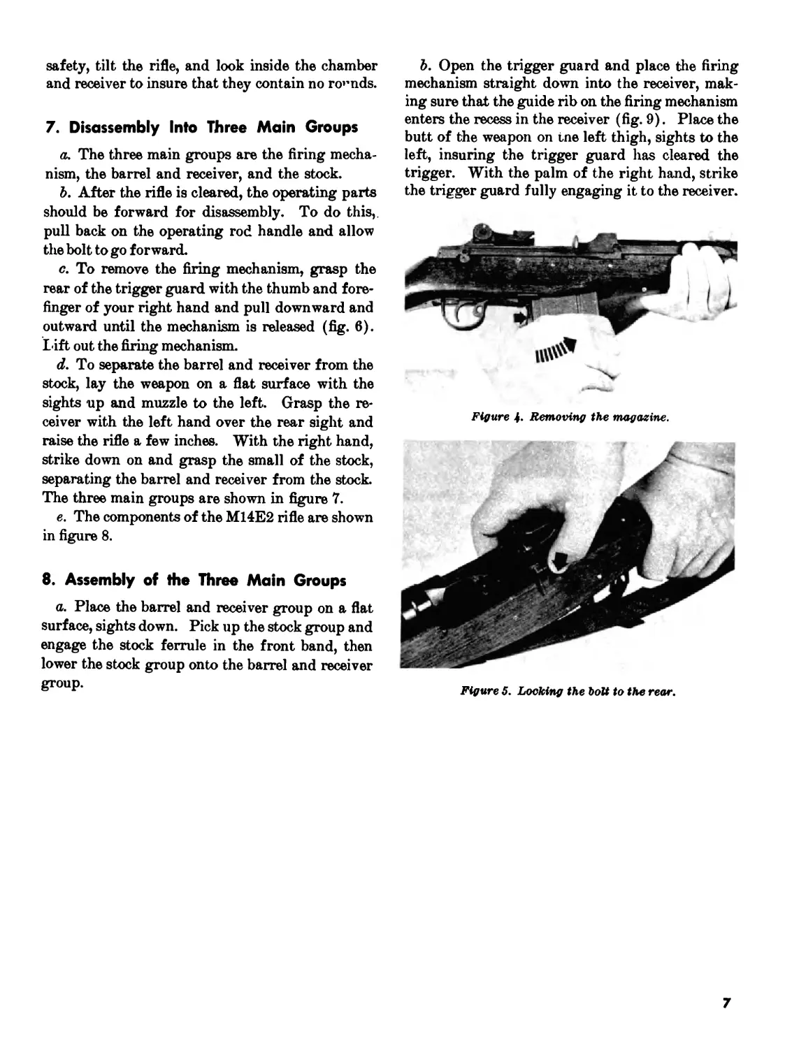
ing the magazine.) Remove the magazine by plac-
ing the right thumb on the magazine latch and
curl the remaining fingers around the front of the
magazine. Press in on the magazine latch, rotate
the base of the magazine toward the muzzle end
of the rifle (fig. 4), and remove it from the maga-
zine well. With the knife edge of the right hand,
pull the operating rod handle all the way to the
rear, reach across the receiver with the right thumb
and press in on the bolt lock (fig. 5). Verify the
Chart I. Disassembly Authorization
Part Indi- vidual soldier Armorer Main- tenance person- nel
SEPARATION INTO THREE MAIN GROUPS X
DISASSEMBLY: BARREL AND RECEIVER GROUP X
Front sight X
Rear sight X
Flash suppressor X
Spindle valve X
Sear release X
Selector and selector shaft lock X
Bipod М2 X
Connector assembly (spring and plunger) X
Bolt lock X
Cartridge clip guide X
Operating rod guide X
Barrel from receiver X
Stabilizer assembly M14E2 X
STOCK GROUP: Stock liner X
Upper sling swivel bracket X
Stock ferrule X
MAGAZINE X
BOLT X
Bolt roller from bolt stud. X
FIRING MECHANISM X
Magazine latch X
Sear from trigger X
6
safety, tilt the rifle, and look inside the chamber
and receiver to insure that they contain no rounds.
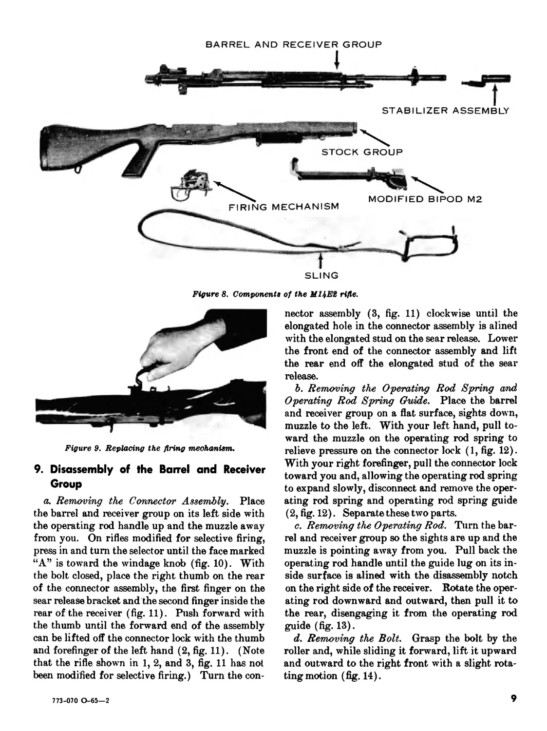
7. Disassembly Into Three Main Groups
a. The three main groups are the firing mecha-
nism, the barrel and receiver, and the stock.
b. After the rifle is cleared, the operating parts
should be forward for disassembly. To do this,,
pull back on the operating rod handle and allow
the bolt to go forward.
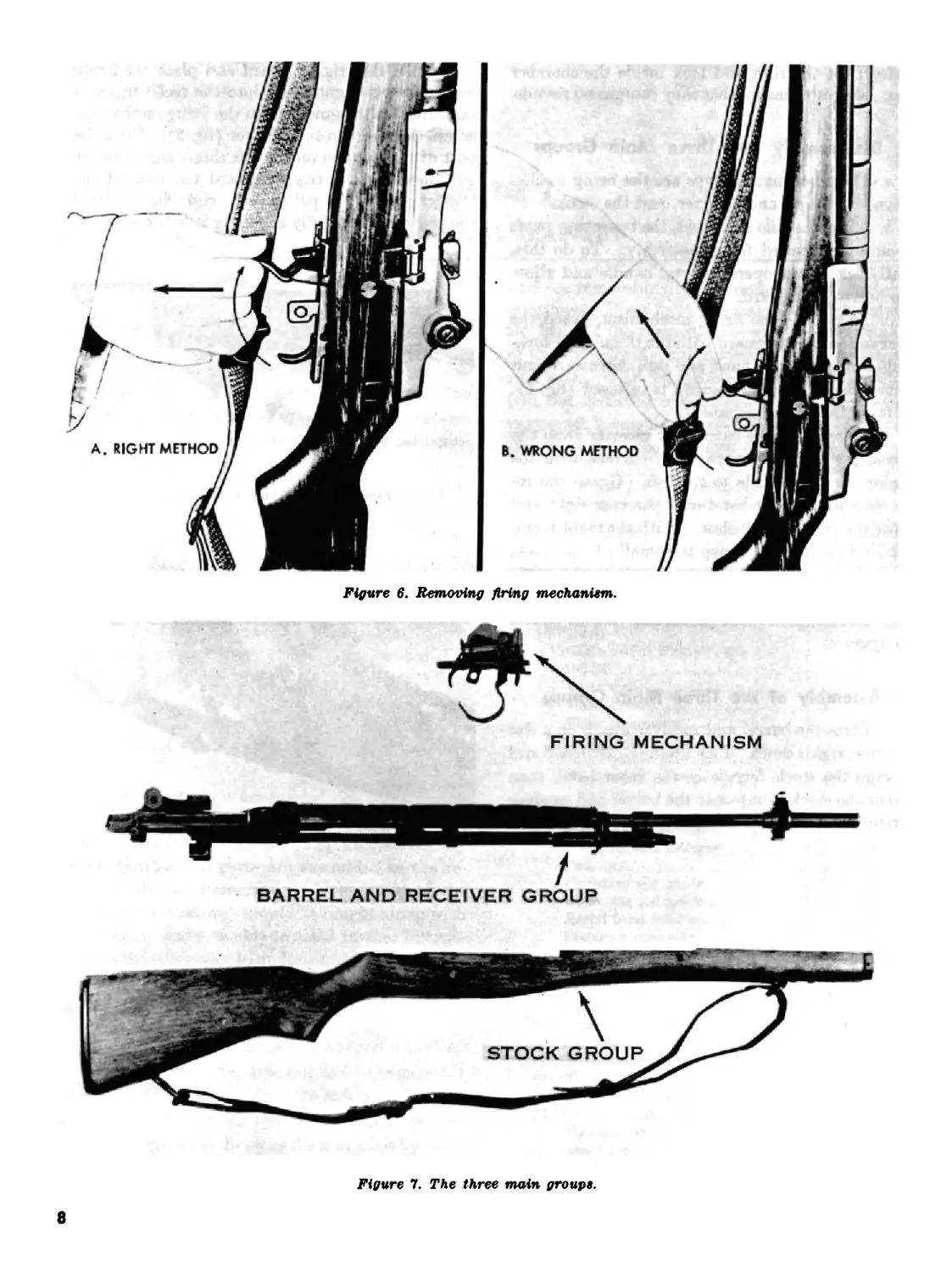
<?. To remove the firing mechanism, grasp the
rear of the trigger guard with the thumb and fore-
finger of your right hand and pull downward and
outward until the mechanism is released (fig. 6).
Lift out the firing mechanism.
d. To separate the barrel and receiver from the
stock, lay the weapon on a flat surface with the
sights up and muzzle to the left. Grasp the re-
ceiver with the left hand over the rear sight and
raise the rifle a few inches. With the right hand,
strike down on and grasp the small of the stock,
separating the barrel and receiver from the stock.
The three main groups are shown in figure 7.
e. The components of the M14E2 rifle are shown
in figure 8.
8. Assembly of the Three Main Groups
a. Place the barrel and receiver group on a flat
surface, sights down. Pick up the stock group and
engage the stock ferrule in the front band, then
lower the stock group onto the barrel and receiver
group.
b. Open the trigger guard and place the firing
mechanism straight down into the receiver, mak-
ing sure that the guide rib on the firing mechanism
enters the recess in the receiver (fig. 9). Place the
butt of the weapon on tne left thigh, sights to the
left, insuring the trigger guard has cleared the
trigger. With the palm of the right hand, strike
the trigger guard fully engaging it to the receiver.
Figure 4- Removing the magazine.
Figure 5. Locking the bolt to the rear.
7
A. RIGHT METHOD
B. WRONG METHOD
Figure 6. Removing firing mechanism.
FIRING MECHANISM
BARREL AND RECEIVER GROUP
STOCK GROUP
Figure 7. The three main groups.
8
BARREL AND RECEIVER GROUP
STABILIZER ASSEMBLY
SLING
Figure 8. Components of the МЦЕЪ rifle.
Figure 9. Replacing the firing mechanism.
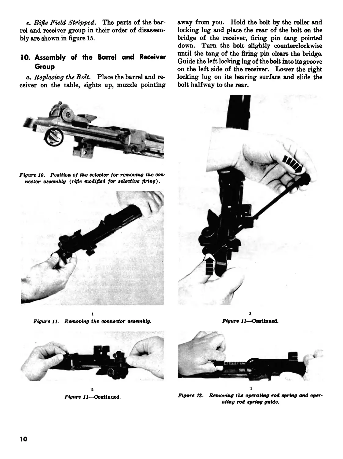
9. Disassembly of the Barrel and Receiver
Group
a. Removing the Connector Assembly. Place
the barrel and receiver group on its left side with
the operating rod handle up and the muzzle away
from you. On rifles modified for selective firing,
press in and turn the selector until the face marked
“A” is toward the windage knob (fig. 10). With
the bolt closed, place the right thumb on the rear
of the connector assembly, the first finger on the
sear release bracket and the second finger inside the
rear of the receiver (fig. 11). Push forward with
the thumb until the forward end of the assembly
can be lifted off the connector lock with the thumb
and forefinger of the left hand (2, fig. 11). (Note
that the rifle shown in 1, 2, and 3, fig. 11 has not
been modified for selective firing.) Turn the con-
nector assembly (3, fig. 11) clockwise until the
elongated hole in the connector assembly is alined
with the elongated stud on the sear release. Lower
the front end of the connector assembly and lift
the rear end off the elongated stud of the sear
release.
b. Removing the Operating Rod Spring and
Operating Rod Spring Guide. Place the barrel
and receiver group on a flat surface, sights down,
muzzle to the left. With your left hand, pull to-
ward the muzzle on the operating rod spring to
relieve pressure on the connector lock (1, fig. 12).
With your right forefinger, pull the connector lock
toward you and, allowing the operating rod spring
to expand slowly, disconnect and remove the oper-
ating rod spring and operating rod spring guide
(2, fig. 12). Separate these two parts.
c. Removing the Operating Rod. Turn the bar-
rel and receiver group so the sights are up and the
muzzle is pointing away from you. Pull back the
operating rod handle until the guide lug on its in-
side surface is alined with the disassembly notch
on the right side of the receiver. Rotate the oper-
ating rod downward and outward, then pull it to
the rear, disengaging it from the operating rod
guide (fig. 13).
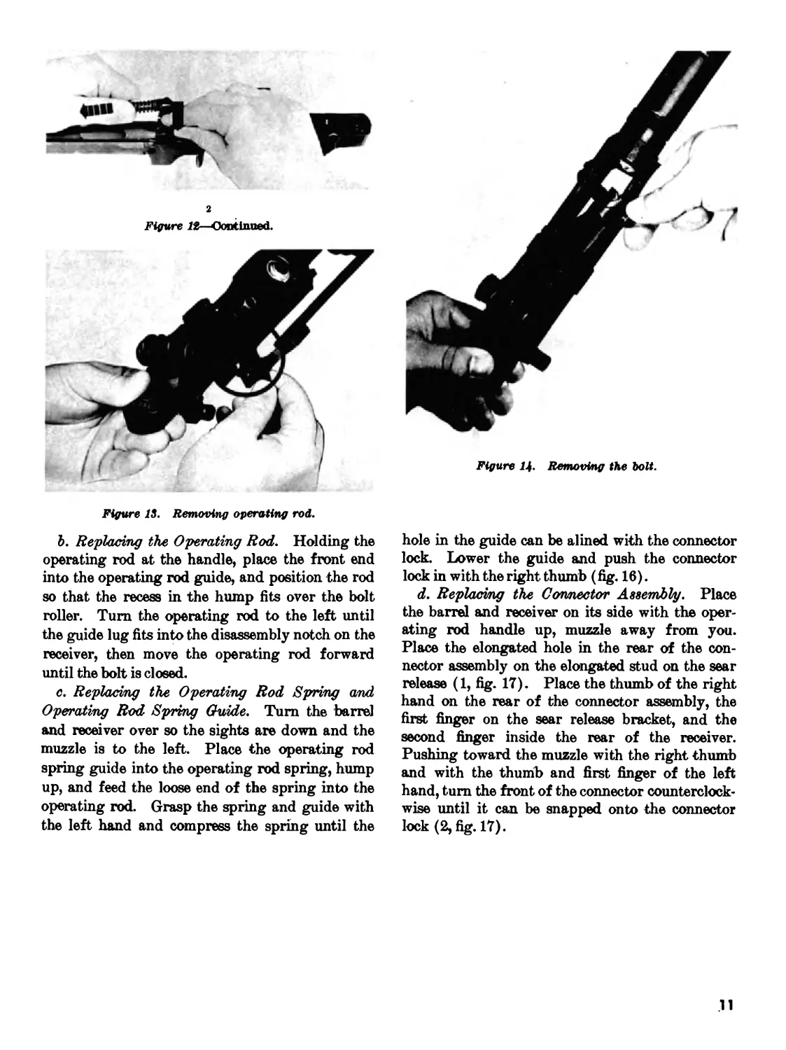
d. Removing the Bolt. Grasp the bolt by the
roller and, while sliding it forward, lift it upward
and outward to the right front with a slight rota-
ting motion (fig. 14).
773-070 0-65—2
9
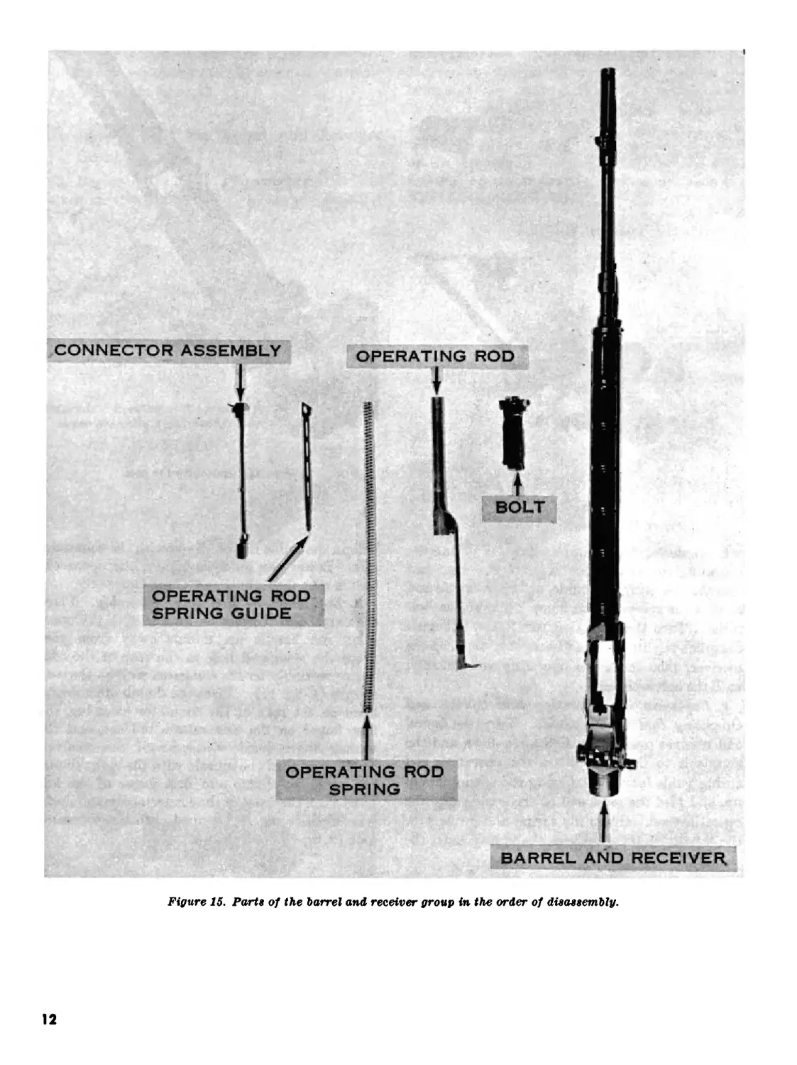
e. Rifle Field Stripped. The parts of the bar-
rel and receiver group in their order of disassem-
bly are shown in figure 15.
10. Assembly of the Barrel and Receiver
Group
a. Replacing the Bolt. Place the barrel and re-
ceiver on the table, sights up, muzzle pointing
away from you. Hold the bolt by the roller and
locking lug and place the rear of the bolt on the
bridge of the receiver, firing pin tang pointed
down. Turn the bolt slightly counterclockwise
until the tang of the firing pin clears the bridge.
Guide the left locking lug of the bolt into its groove
on the left side of the receiver. Lower the right
locking lug on its bearing surface and slide the
bolt halfway to the rear.
Figure 10. Position of the selector for removing the con-
nector assembly (rifle modified for selective firing).
i
Figure 11. Removing the connector assembly.
з
Figure 11—Continued.
2
Figure 11—Continued.
i
Figure 12. Removing the operating rod spring and oper-
ating rod spring guide.
10
Figure 12—Continued.
Figure Ц. Removing the bolt.
Figure IS. Removing operating rod.
b. Replacing the Operating Rod. Holding the
operating rod at the handle, place the front end
into the operating rod guide, and position the rod
so that the recess in the hump fits over the bolt
roller. Turn the operating rod to the left until
the guide lug fits into the disassembly notch on the
receiver, then move the operating rod forward
until the bolt is closed.
c. Replacing the Operating Rod Spring and
Operating Rod Spring Guide. Turn the barrel
and receiver over so the sights are down and the
muzzle is to the left. Place the operating rod
spring guide into the operating rod spring, hump
up, and feed the loose end of the spring into the
operating rod. Grasp the spring and guide with
the left hand and compress the spring until the
hole in the guide can be alined with the connector
lock. Lower the guide and push the connector
lock in with the right thumb (fig. 16).
d. Replacing the Connector Assembly. Place
the barrel and receiver on its side with the oper-
ating rod handle up, muzzle away from you.
Place the elongated hole in the rear of the con-
nector assembly on the elongated stud on the sear
release (1, fig. 17). Place the thumb of the right
hand on the rear of the connector assembly, the
first finger on the sear release bracket, and the
second finger inside the rear of the receiver.
Pushing toward the muzzle with the right thumb
and with the thumb and first finger of the left
hand, turn the front of the connector counterclock-
wise until it can be snapped onto the connector
lock (2, fig. 17).
11
BARREL AND RECEIVER.
Figure 15. Parts of the barrel and receiver group in the order of disassembly.
12
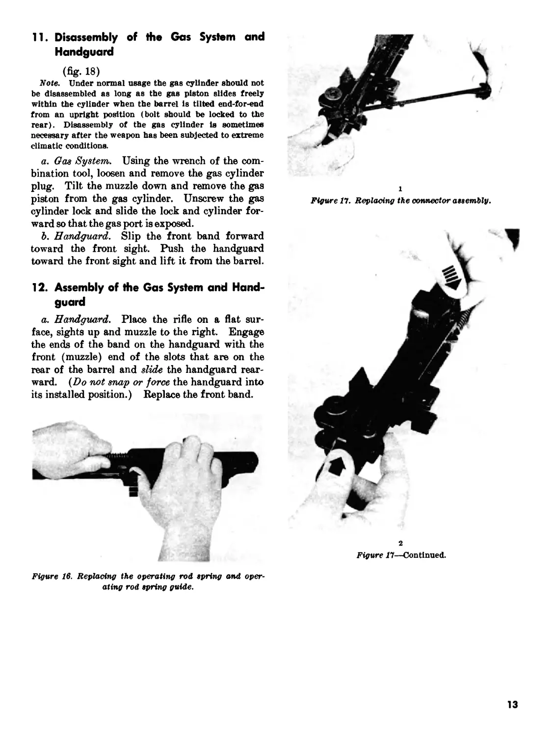
11. Disassembly of the Gas System and
Handguard
(% 18)
"Note. Under normal usage the gas cylinder should not
be disassembled as long as the gas piston slides freely
within the cylinder when the barrel is tilted end-for-end
from an upright position (bolt should be locked to the
rear). Disassembly of the gas cylinder is sometimes
necessary after the weapon has been subjected to extreme
climatic conditions.
a. Gas System. Using the wrench of the com-
bination tool, loosen and remove the gas cylinder
plug. Tilt the muzzle down and remove the gas
piston from the gas cylinder. Unscrew the gas
cylinder lock and slide the lock and cylinder for-
ward so that the gas port is exposed.
b. Handguard. Slip the front band forward
toward the front sight. Push the handguard
toward the front sight and lift it from the barrel.
12. Assembly of the Gas System and Hand-
guard
a. Handguard. Place the rifle on a flat sur-
face, sights up and muzzle to the right. Engage
the ends of the band on the handguard with the
front (muzzle) end of the slots that are on the
rear of the barrel and slide the handguard rear-
ward. (Do not snap or force the handguard into
its installed position.) Kepiace the front band.
1
Figure 11. Replacing the connector assembly.
2
Figure П—Continued.
Figure 16. Replacing the operating rod spring and oper-
ating rod spring guide.
13
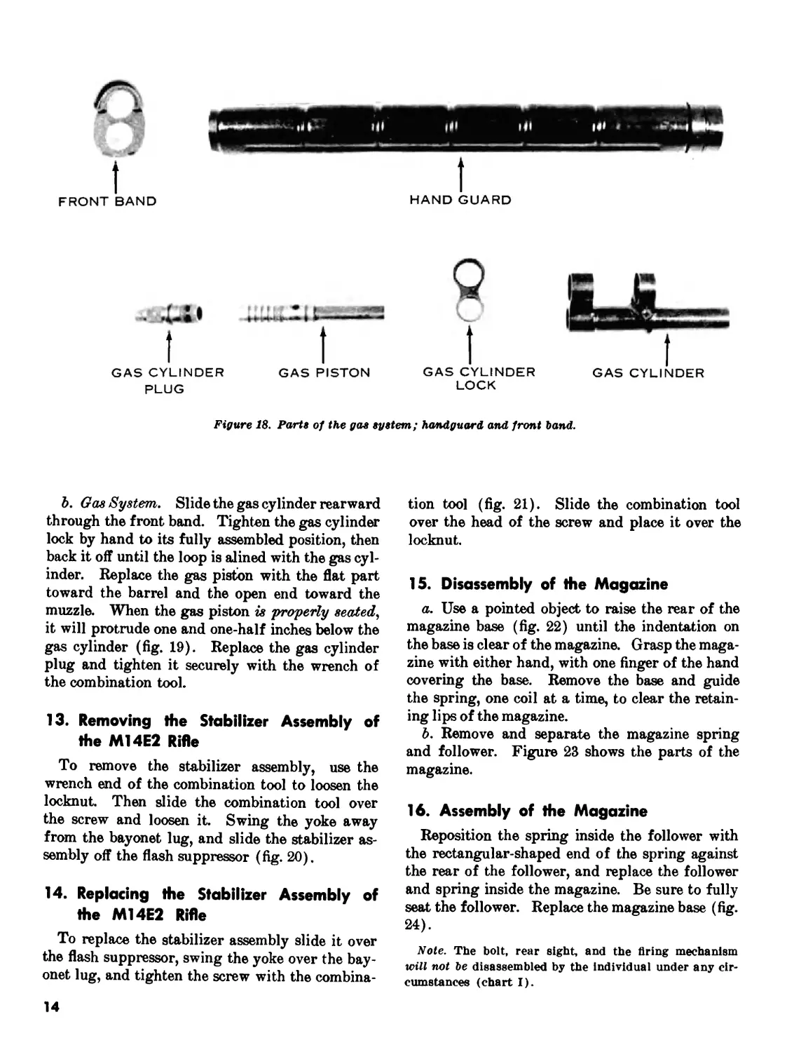
HAND GUARD
FRONT BAND
GAS PISTON
GAS CYLINDER
PLUG
GAS CYLINDER
LOCK
GAS CYLINDER
Figure 18. Parts of the gas system; handguard and front band.
b. Gas System. Slide the gas cylinder rearward
through the front band. Tighten the gas cylinder
lock by hand to its fully assembled position, then
back it off until the loop is alined with the gas cyl-
inder. Replace the gas piston with the flat part
toward the barrel and the open end toward the
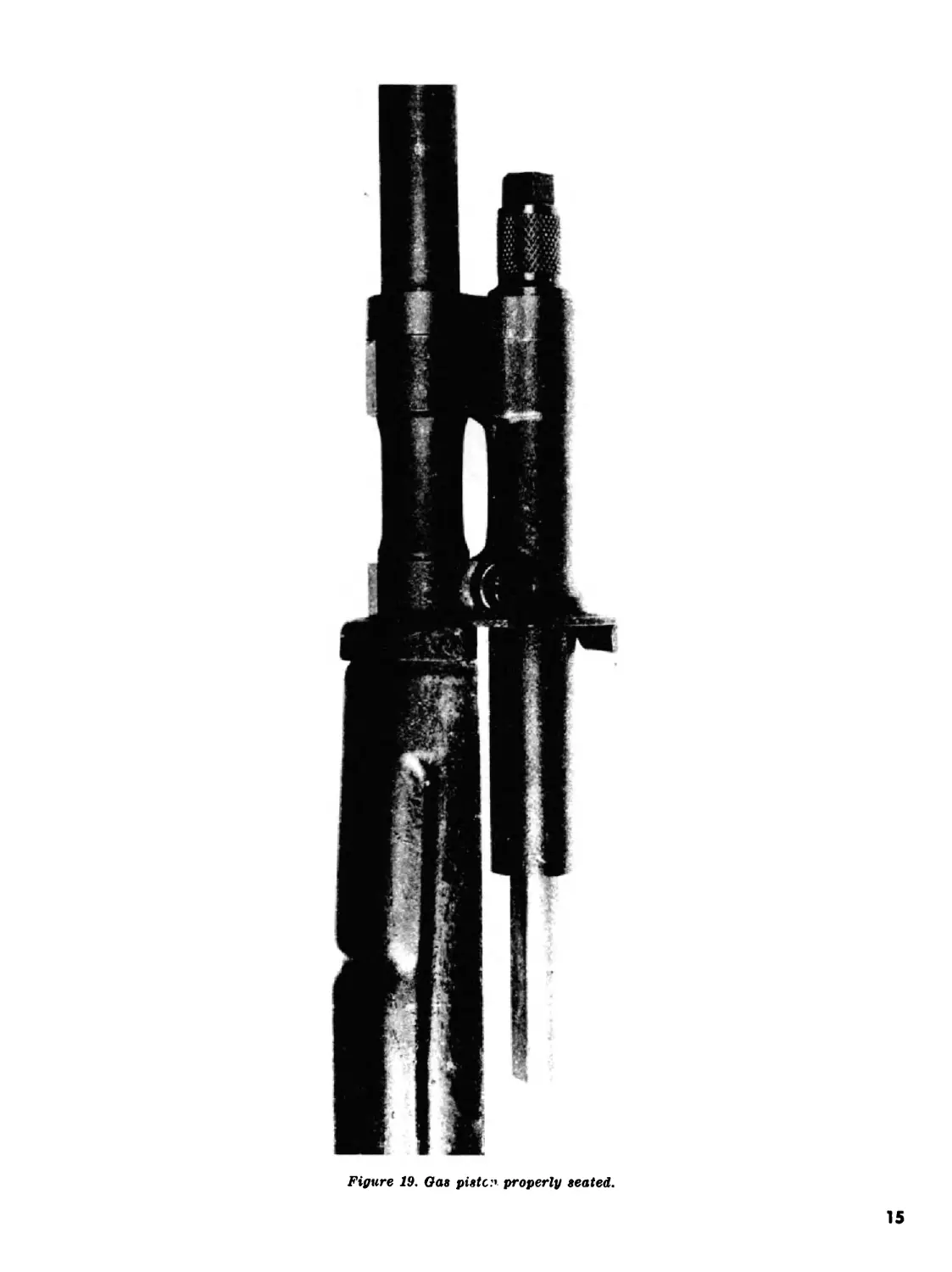
muzzle. When the gas piston is properly seated,
it will protrude one and one-half inches below the
gas cylinder (fig. 19). Replace the gas cylinder
plug and tighten it securely with the wrench of
the combination tool.
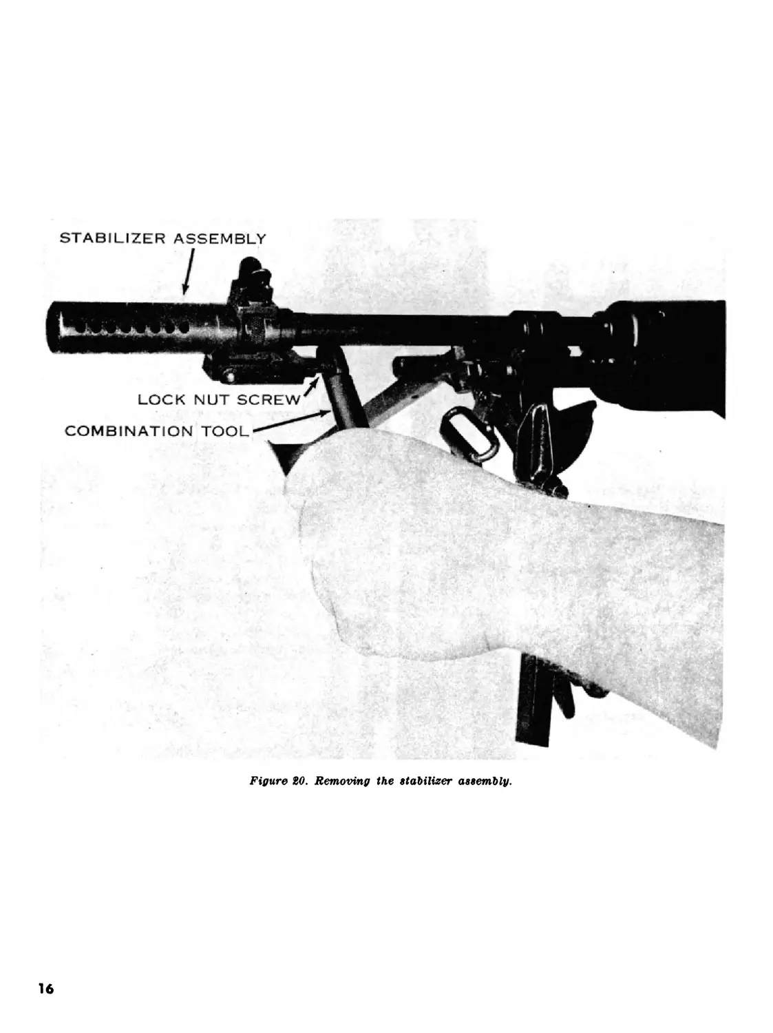
13. Removing the Stabilizer Assembly of
the M14E2 Rifle
To remove the stabilizer assembly, use the
wrench end of the combination tool to loosen the
locknut. Then slide the combination tool over
the screw and loosen it. Swing the yoke away
from the bayonet lug, and slide the stabilizer as-
sembly off the flash suppressor (fig. 20).
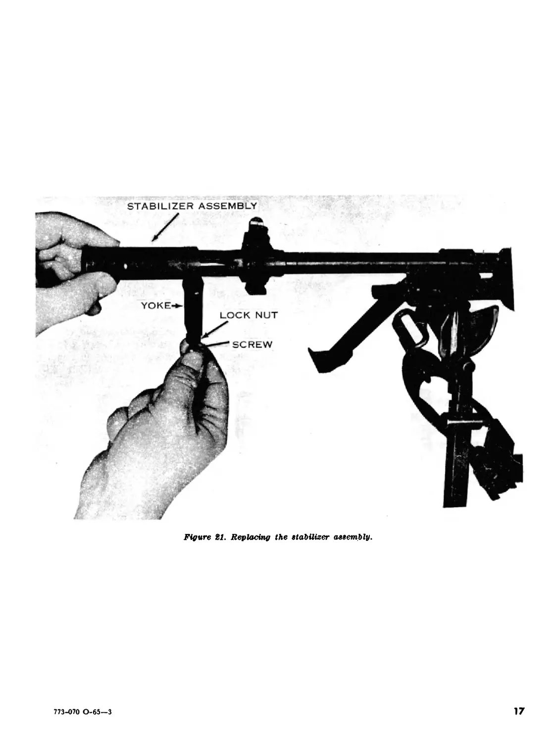
14. Replacing the Stabilizer Assembly of
the M14E2 Rifle
To replace the stabilizer assembly slide it over
the flash suppressor, swing the yoke over the bay-
onet lug, and tighten the screw with the combina-
tion tool (fig. 21). Slide the combination tool
over the head of the screw and place it over the
locknut.
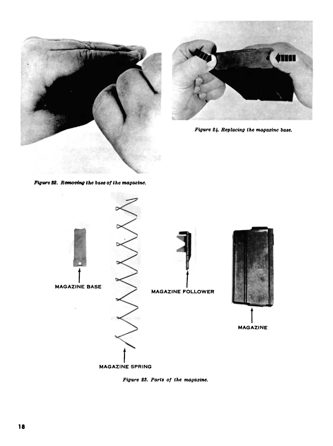
15. Disassembly of the Magazine
a. Use a pointed object to raise the rear of the
magazine base (fig. 22) until the indentation on
the base is clear of the magazine. Grasp the maga-
zine with either hand, with one finger of the hand
covering the base. Remove the base and guide
the spring, one coil at a time, to clear the retain-
ing lips of the magazine.
b. Remove and separate the magazine spring
and follower. Figure 23 shows the parts of the
magazine.
16. Assembly of the Magazine
Reposition the spring inside the follower with
the rectangular-shaped end of the spring against
the rear of the follower, and replace the follower
and spring inside the magazine. Be sure to fully
seat the follower. Replace the magazine base (fig.
24).
Note. The bolt, rear sight, and the firing mechanism
will not be disassembled by the individual under any cir-
cumstances (chart I).
14
Figure 19. Gas piste:' properly seated.
STABILIZER ASSEMBLY
Figure £0. Removing the stabilizer assembly.
16
STABILIZER ASSEMBLY
Figure 21. Replacing the stabilizer assembly.
773-070 0-65—3
17
Figure 22. Removing the base of the magazine.
Figure 24. Replacing the magazine base.
MAGAZINE
18
CHAPTER 3
OPERATION AND FUNCTIONING
Section I. OPERATION
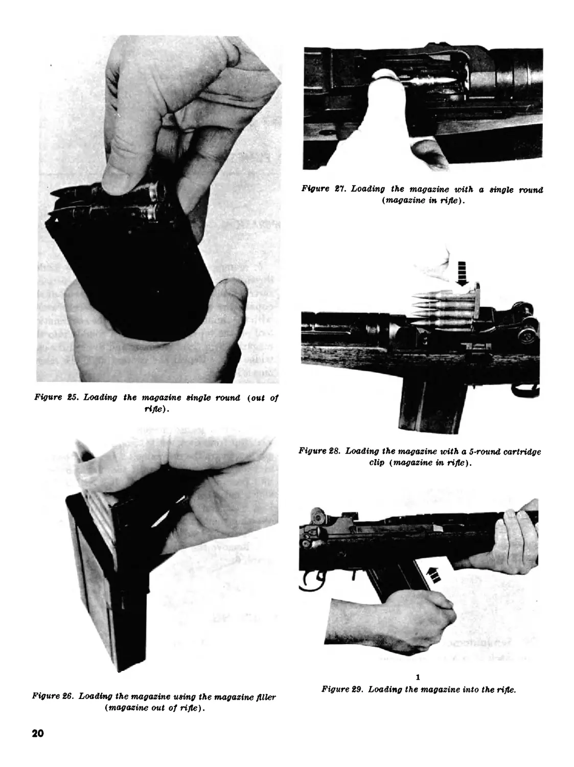
17. Loading the Magazine (Out of the Rifle)
a. Place each round on top of the magazine
follower (with the bullet end toward the front of
the magazine) and apply pressure with the thumb
to fully seat the round in the magazine (fig. 25).
b. To load the magazine with a 5-round car-
tridge clip, the magazine filler is used (fig. 26).
Slide the filler over the top rear portion of the
magazine and insert a 5-round cartridge clip into
the filler. Place either the thumb or the open end
of the combination tool on the top round and push
the 5 rounds into the magazine. Remove the clip
and repeat the process until 20 rounds have been
loaded into the magazine, then remove the maga-
zine filler.
18. Loading the Magazine (in the Rifle)
a. To load a single round into an empty maga-
zine in the weapon, lock the bolt to the rear and
engage the safety. Place a round on top of the
magazine follower and press down on the round
and fully seat it in the magazine (fig. 27).
b. A magazine in the weapon can be loaded
through the top of the receiver with a 5-round
cartridge clip. To do this, place either end of the
clip in the cartridge guide, then exert pressure
with the thumb or the open end of the combination
tool on the top round, forcing 5 rounds into the
magazine (fig. 28). Remove and discard the car-
tridge clip. Repeat the process until the maga-
zine is loaded.
19. Loading and Unloading the Rifle
a. Place the safety in the safe position.
b. Insert a loaded magazine into the magazine
well, top front first, until the operating rod spring
guide engages the magazine (1, fig. 29), then pull
backward and upward until the magazine snaps
into position (2, fig. 29). A click will be heard
which indicates that the magazine is fully seated.
Pull back and release the operating rod handle,
allowing the bolt to strip the top round from the
magazine and load it into the chamber.
c. Remove the magazine as described in para-
graph 6.
Section II. FUNCTIONING
20. Semiautomatic
a. Each time a round is fired, the parts inside
the rifle work together in a given order. This is
the cycle of operation. This cycle is similar in all
small arms. A knowledge of what happens inside
the rifle during the cycle of operation will help you
to understand the causes of, and remedies for,
various stoppages.
19
Figure 25. Loading the magazine single round (out of
rifle).
Figure 21. Loading the magazine with a single round
(magazine in rifle).
Figure 28. Loading the magazine with a 5-round cartridge
clip (magazine in rifle).
Figure 26. Loading the magazine using the magazine filler
(magazine out of rifle).
1
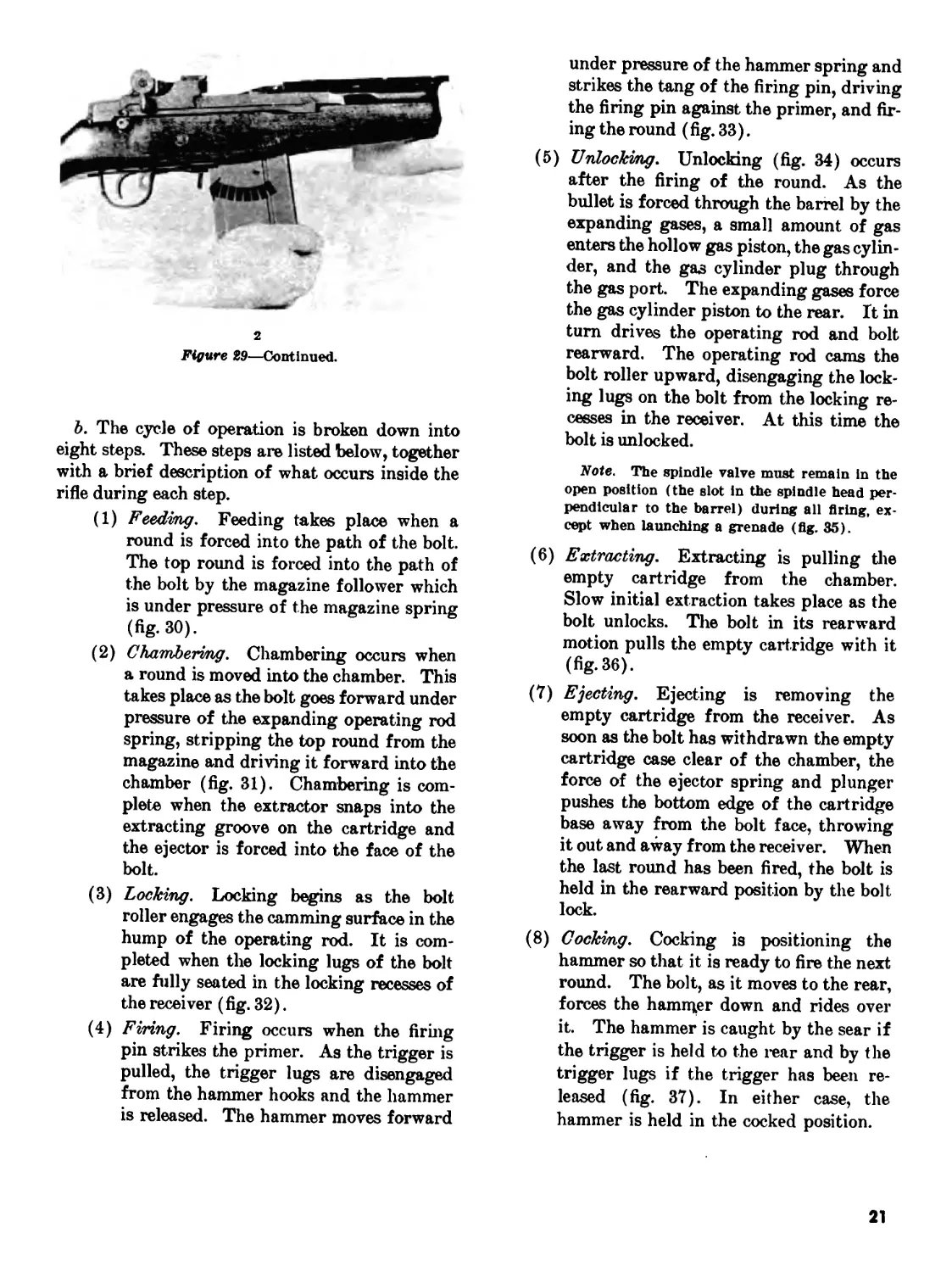
Figure 29. Loading the magazine into the rifle.
20
2
Figure 29—Continued.
b. The cycle of operation is broken down into
eight steps. These steps are listed below, together
with a brief description of what occurs inside the
rifle during each step.
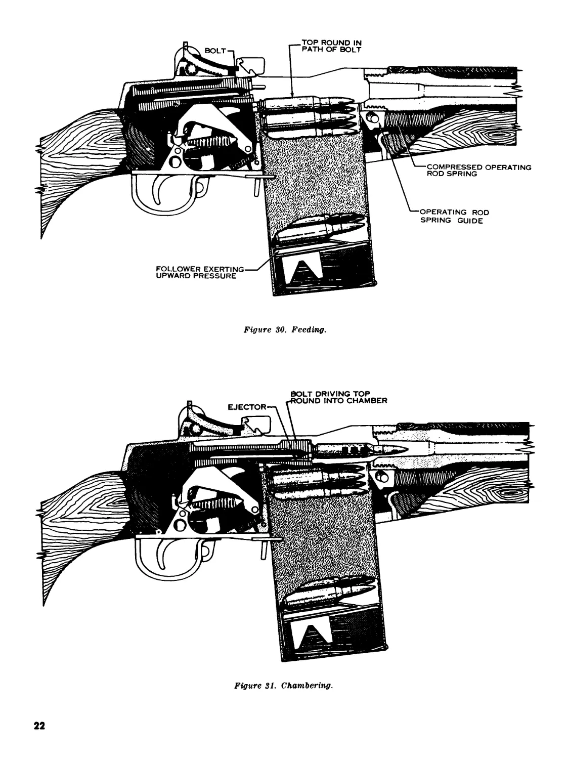
(1) Feeding. Feeding takes place when a
round is forced into the path of the bolt.
The top round is forced into the path of
the bolt by the magazine follower which
is under pressure of the magazine spring
(fig. 30).
(2) Chambering. Chambering occurs when
a round is moved into the chamber. This
takes place as the bolt goes forward under
pressure of the expanding operating rod
spring, stripping the top round from the
magazine and driving it forward into the
chamber (fig. 31). Chambering is com-
plete when the extractor snaps into the
extracting groove on the cartridge and
the ejector is forced into the face of the
bolt.
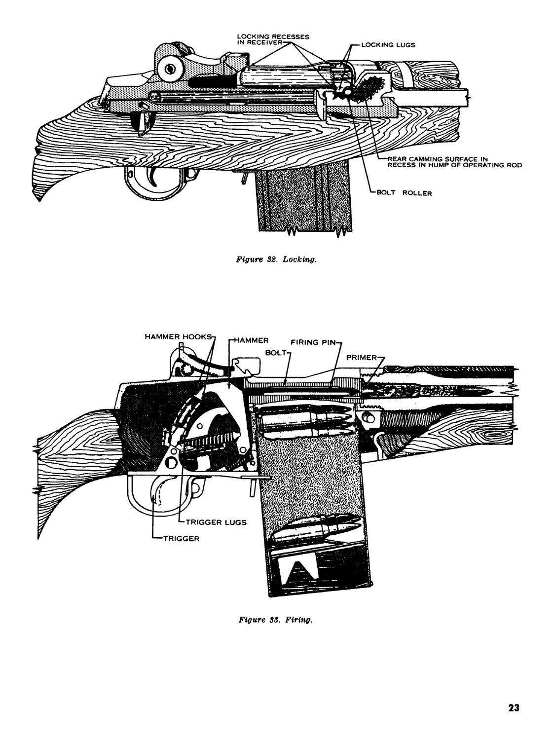
(3) Locking. Locking begins as the bolt
roller engages the camming surface in the
hump of the operating rod. It is com-
pleted when the locking lugs of the bolt
are fully seated in the locking recesses of
the receiver (fig. 32).
(4) Firing. Firing occurs when the firing
pin strikes the primer. As the trigger is
pulled, the trigger lugs are disengaged
from the hammer hooks and the hammer
is released. The hammer moves forward
under pressure of the hammer spring and
strikes the tang of the firing pin, driving
the firing pin against the primer, and fir-
ing the round (fig. 33).
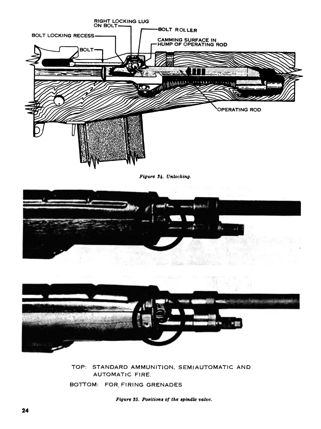
(5) Unlocking. Unlocking (fig. 34) occurs
after the firing of the round. As the
bullet is forced through the barrel by the
expanding gases, a small amount of gas
enters the hollow gas piston, the gas cylin-
der, and the gas cylinder plug through
the gas port. The expanding gases force
the gas cylinder piston to the rear. It in
turn drives the operating rod and bolt
rearward. The operating rod cams the
bolt roller upward, disengaging the lock-
ing lugs on the bolt from the locking re-
cesses in the receiver. At this time the
bolt is unlocked.
Note. The spindle valve must remain in the
open position (the slot in the spindle head per-
pendicular to the barrel) during all firing, ex-
cept when launching a grenade (fig. 35).
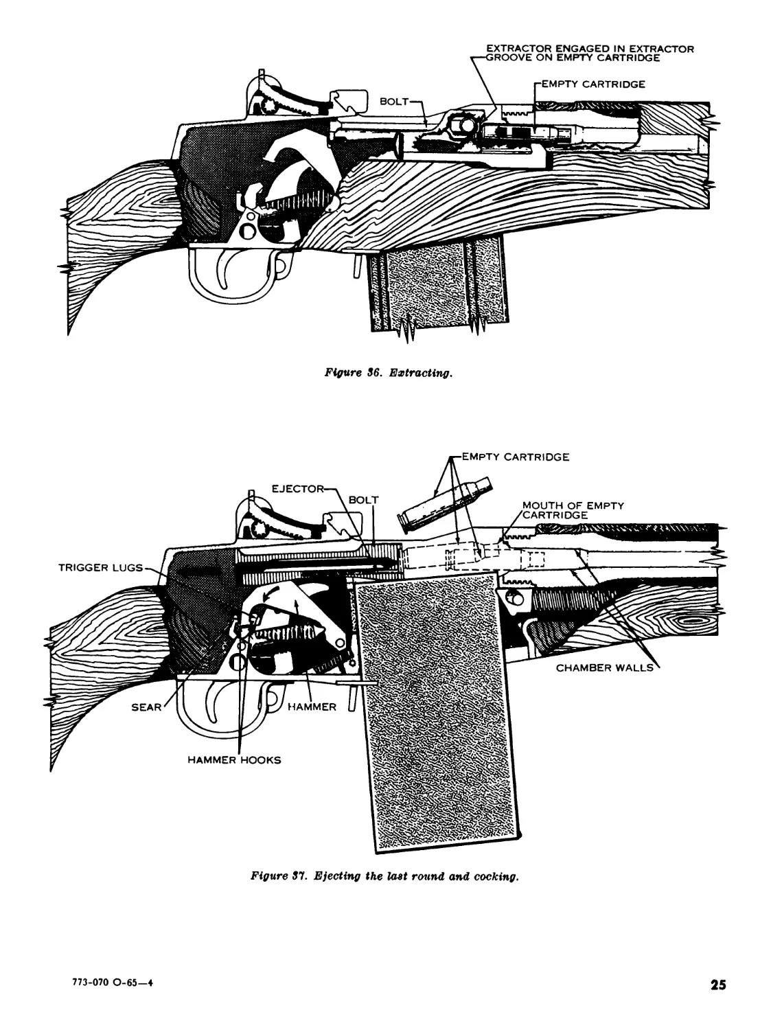
(6) Extracting. Extracting is pulling the
empty cartridge from the chamber.
Slow initial extraction takes place as the
bolt unlocks. The bolt in its rearward
motion pulls the empty cartridge with it
(fig. 36).
(7) Ejecting. Ejecting is removing the
empty cartridge from the receiver. As
soon as the bolt has withdrawn the empty
cartridge case clear of the chamber, the
force of the ejector spring and plunger
pushes the bottom edge of the cartridge
base away from the bolt face, throwing
it out and away from the receiver. When
the last round has been fired, the bolt is
held in the rearward position by the bolt
lock.
(8) Cocking. Cocking is positioning the
hammer so that it is ready to fire the next
round. The bolt, as it moves to the rear,
forces the hammer down and rides over
it. The hammer is caught by the sear if
the trigger is held to the rear and by the
trigger lugs if the trigger has been re-
leased (fig. 37). In either case, the
hammer is held in the cocked position.
21
Figure 30. Feeding.
BOLT DRIVING TOP
Figure 31. Chambering.
22
LOCKING RECESSES
Figure 32. Locking.
Figure 33. Firing.
23
BOLT ROLLER
BOLT LOCKING RECESS
BOLT
CAMMING SURFACE IN
HUMP OF OPERATING ROD
RIGHT LOCKING LUG
ON BOLT
OPERATING ROD
Figure 34- Unlocking.
TOP: STANDARD AMMUNITION. SEMIAUTOMATIC AND
AUTOMATIC FIRE.
BOTTOM: FOR. FIRING GRENADES
Figure 35. Position s of the spindle valve.
24
EXTRACTOR ENGAGED IN EXTRACTOR
Figure 86. Extracting.
Figure 37. Ejecting the last round and cocking.
773-070 0-65—4
25
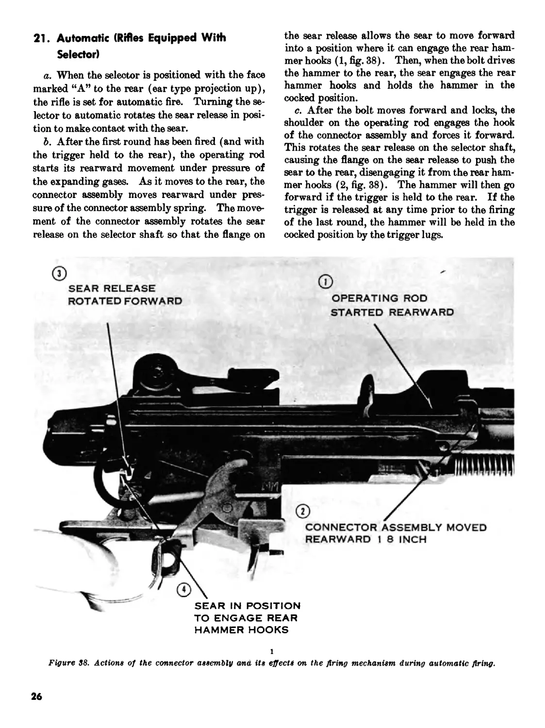
21. Automatic (Rifles Equipped With
Selector)
a. When the selector is positioned with the face
marked “A” to the rear (ear type projection up),
the rifle is set for automatic fire. Turning the se-
lector to automatic rotates the sear release in posi-
tion to make contact with the sear.
b. After the first round has been fired (and with
the trigger held to the rear), the operating rod
starts its rearward movement under pressure of
the expanding gases. As it moves to the rear, the
connector assembly moves rearward under pres-
sure of the connector assembly spring. The move-
ment of the connector assembly rotates the sear
release on the selector shaft so that the flange on
the sear release allows the sear to move forward
into a position where it can engage the rear ham-
mer hooks (1, fig. 38). Then, when the bolt drives
the hammer to the rear, the sear engages the rear
hammer hooks and holds the hammer in the
cocked position.
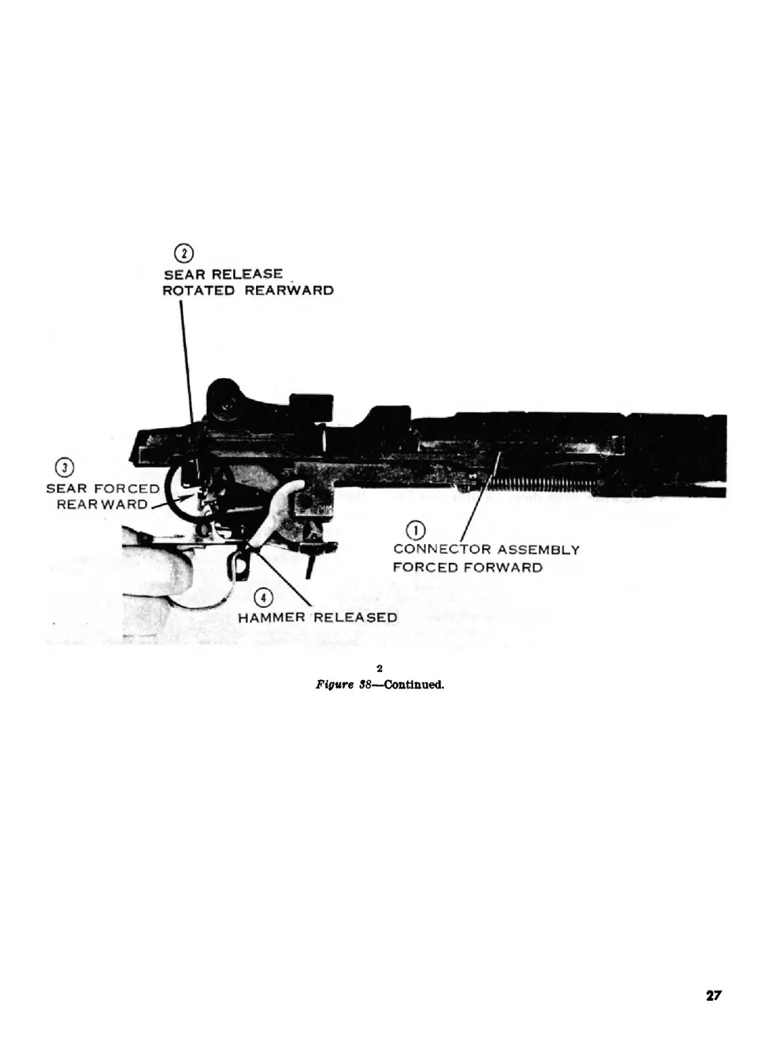
c. After the bolt moves forward and locks, the
shoulder on the operating rod engages the hook
of the connector assembly and forces it forward.
This rotates the sear release on the selector shaft,
causing the flange on the sear release to push the
sear to the rear, disengaging it from the rear ham-
mer hooks (2, fig. 38). The hammer will then go
forward if the trigger is held to the rear. If the
trigger is released at any time prior to the firing
of the last round, the hammer will be held in the
cocked position by the trigger lugs.
SEAR RELEASE
ROTATED FORWARD
OPERATING ROD
STARTED REARWARD
TO ENGAGE REAR
HAMMER HOOKS
1
Figure 88. Actions of the connector assembly ana its effects on the firing mechanism during automatic firing.
26
SEAR RELEASE
ROTATED REARWARD
HAMMER RELEASED
2
Figure 38—Continued.
27
CHAPTER 4
STOPPAGES AND IMMEDIATE ACTION
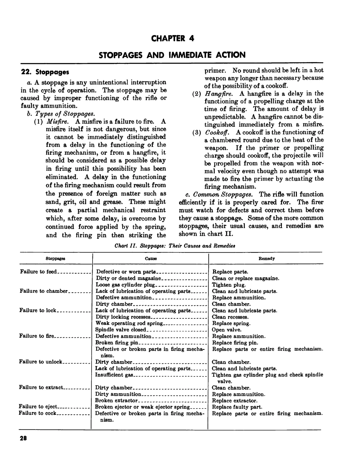
22. Stoppages
a. A stoppage is any unintentional interruption
in the cycle of operation. The stoppage may be
caused by improper functioning of the rifle or
faulty ammunition.
b. Types of Stoppages.
(1) Misfire. A misfire is a failure to fire. A
misfire itself is not dangerous, but since
it cannot be immediately distinguished
from a delay in the functioning of the
firing mechanism, or from a hangfire, it
should be considered as a possible delay
in firing until this possibility has been
eliminated. A delay in the functioning
of the firing mechanism could result from
the presence of foreign matter such as
sand, grit, oi] and grease. These might
create a partial mechanical restraint
which, after some delay, is overcome by
continued force applied by the spring,
and the firing pin then striking the
primer. No round should be left in a hot
weapon any longer than necessary because
of the possibility of a cookoff.
(2) Hangfire. A hangfire is a delay in the
functioning of a propelling charge at the
time of firing. The amount of delay is
unpredictable. A hangfire cannot be dis-
tinguished immediately from a misfire.
(3) Cookoff. A cookoff is the functioning of
a chambered round due to the heat of the
weapon. If the primer or propelling
charge should cookoff, the projectile will
be propelled from the weapon with nor-
mal velocity even though no attempt was
made to fire the primer by actuating the
firing mechanism.
c. Common Stoppages. The rifle will function
efficiently if it is properly cared for. The firer
must watch for defects and correct them before
they cause a stoppage. Some of the more common
stoppages, their usual causes, and remedies are
shown in chart II.
Chart II. Stoppages: Their Causes and Remedies
Stoppages Cause Remedy
Failure to feed Defective or worn parts Replace parts. Clean or replace magazine. Tighten plug. Clean and lubricate parts. Replace ammunition. Clean chamber. Clean and lubricate parts. Clean recesses. Replace spring. Open valve. Replace ammunition. Replace firing pin. Replace parts or entire firing mechanism. Clean chamber. Clean and lubricate parts. Tighten gas cylinder plug and check spindle valve. Clean chamber. Replace ammunition. Replace extractor. Replace faulty part. Replace parts or entire firing mechanism.
Failure to chamber Dirty or dented magazine
Loose gas cylinder plug
Lack of lubrication of operating parts
Failure to lock Defective ammunition
Dirty chamber
Lack of lubrication of operating parts
Failure to fire Dirty locking recesses
Weak operating rod spring
Spindle valve closed
Defective ammunition
Failure to unlock Broken firing pin
Defective or broken parts in firing mecha- nism. Dirty chamber
Failure to extract—.. Lack of lubrication of operating parts
Insufficient gas
Dirty chamber
Failure to eject Dirty ammunition
Broken extractor
Broken ejector or weak ejector spring Defective or broken parts in firing mecha- nism.
Failure to cock
28
23. Immediate Action
Immediate action is the unhesitating application
of a probable remedy to reduce a stoppage without
investigating the cause. Immediate action is
taught in two phases.
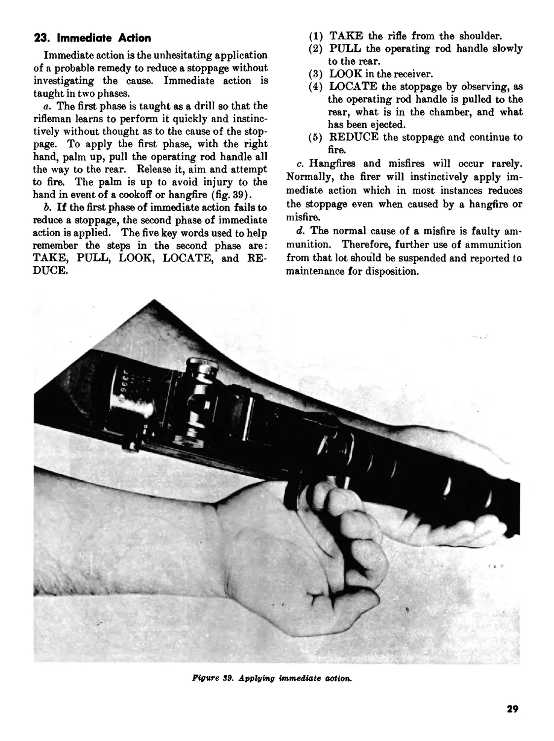
a. The first phase is taught as a drill so that the
rifleman learns to perform it quickly and instinc-
tively without thought as to the cause of the stop-
page. To apply the first phase, with the right
hand, palm up, pull the operating rod handle all
the way to the rear. Release it, aim and attempt
to fire. The palm is up to avoid injury to the
hand in event of a cookoff or hangfire (fig. 39).
b. If the first phase of immediate action fails to
reduce a stoppage, the second phase of immediate
action is applied. The five key words used to help
remember the steps in the second phase are:
TAKE, PULL, LOOK, LOCATE, and RE-
DUCE.
(1) TAKE the rifle from the shoulder.
(2) PULL the operating rod handle slowly
to the rear.
(3) LOOK in the receiver.
(4) LOCATE the stoppage by observing, as
the operating rod handle is pulled to the
rear, what is in the chamber, and what
has been ejected.
(5) REDUCE the stoppage and continue to
fire.
c. Hangfires and misfires will occur rarely.
Normally, the firer will instinctively apply im-
mediate action which in most instances reduces
the stoppage even when caused by a hangfire or
misfire.
d. The normal cause of a misfire is faulty am-
munition. Therefore, further use of ammunition
from that lot should be suspended and reported to
maintenance for disposition.
Figure 89. Applying immediate action.
29
CHAPTER 5
MAINTENANCE
24. General
Maintenance includes all measures taken to keep
the rifle in operating condition. This includes
normal cleaning, inspection for defective parts,
repair, and lubrication.
25. Cleaning Materials, Lubricants, and
Equipment
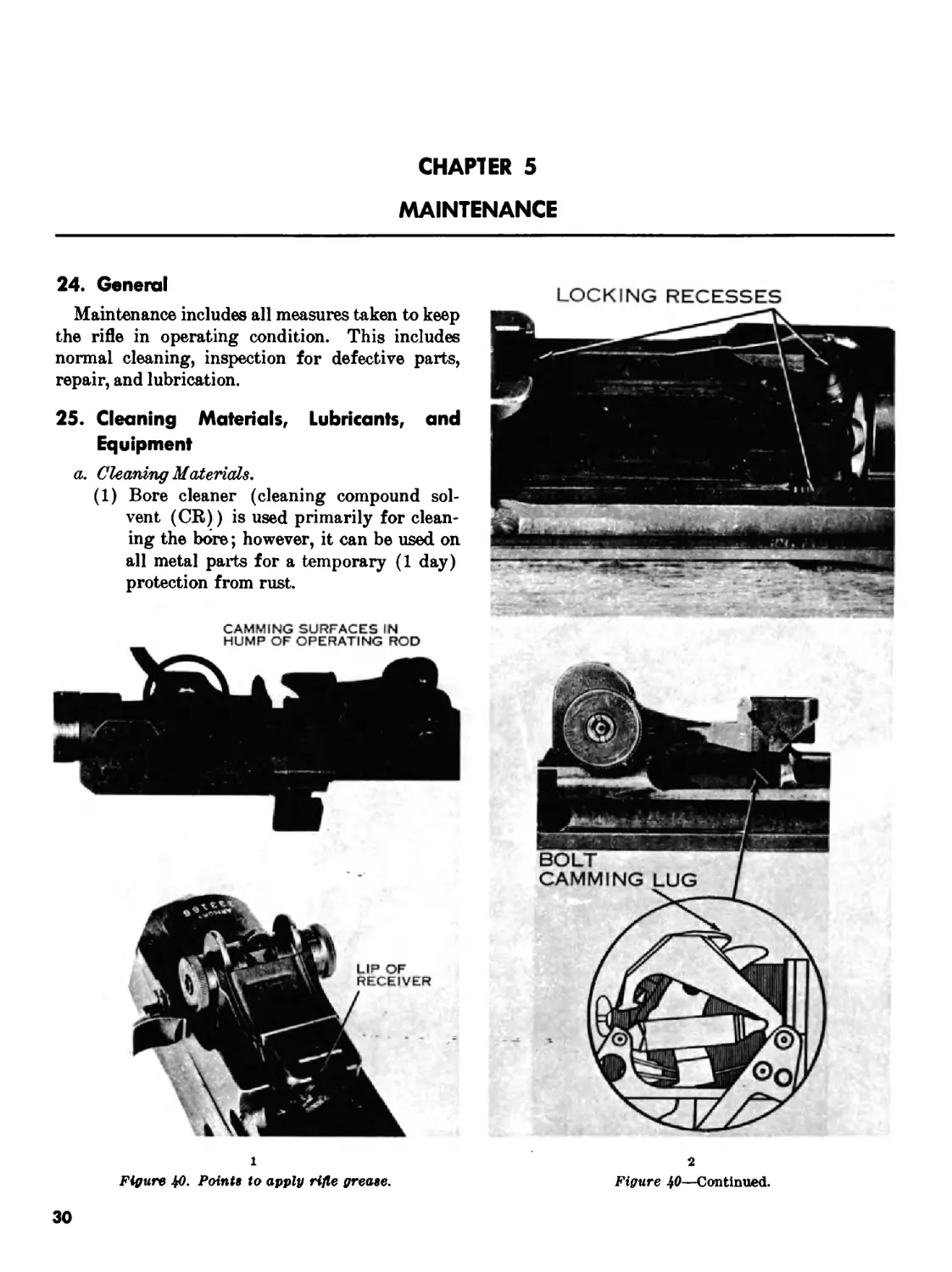
a. Cleaning Materials.
(1) Bore cleaner (cleaning compound sol-
vent (CR)) is used primarily for clean-
ing the bore; however, it can be used on
all metal parts for a temporary (1 day)
protection from rust.
LOCKING RECESSES
CAMMING SURFACES IN
HUMP OF OPERATING ROD
1
Figure JfO. Points to apply rifle grease.
2
Figure 40—Continued.
30
(2) Hot, soapy water or plain hot water is
no substitute for bore cleaner and will
only be used when bore cleaner is not
a/vaalable,
(3) Drycleaning solvent is used for cleaning
rifles which are coated with grease, oil,
or corrosion-preventive compounds.
(4) Carbon-removing compound (PC111-A)
is used on stubborn carbon deposits by
soaking and brushing. This process
must be followed by the use of dryclean-
ing solvent.
b. Lubrioa/nts.
(1) Lubricating oil, general purpose, is used
for lubricating the rifle at normal tem-
peratures (PL special).
(2) Lubricating oil, weapons (LAW) is used
for low temperatures (below 0°).
(3) OE 10 engine oil may be used as a field
expedient under combat conditions when
the oils prescribed in (1) and (2) above
cannot be obtained. However, as soon as
possible the weapon should be cleaned and
lubricated with the proper, authorized
lubricants.
(4) Rifle grease should be applied to those
working surfaces shown in figure 40.
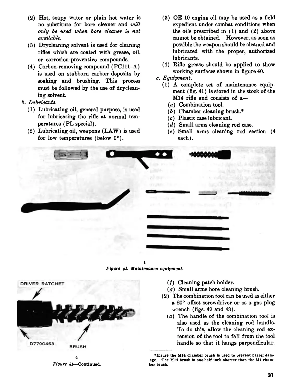
c. Equipment.
(1) A complete set of maintenance equip-
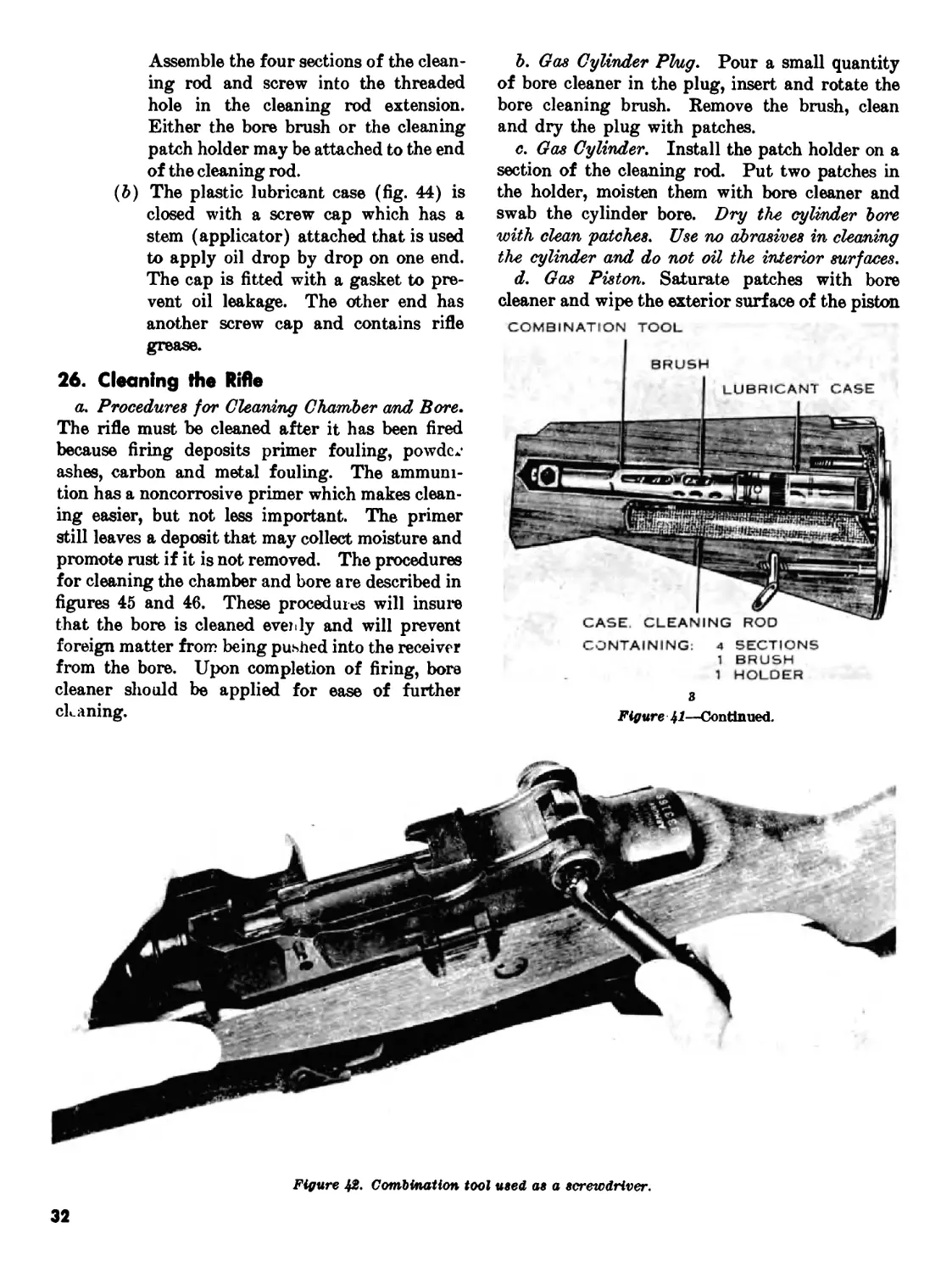
ment (fig. 41) is stored in the stock of the
M14 rifle and consists of a—
(a) Combination tool.
(ft) Chamber cleaning brush.*
(c) Plastic case lubricant.
(<2) Small arms cleaning rod case.
(e) Small arms cleaning rod section (4
each).
i
Figure jl. Maintenance equipment.
DRIVER RATCHET
D779O463
BRUSH
2
Figure 41—Continued.
(/) Cleaning patch holder.
(g) Small arms bore cleaning brush.
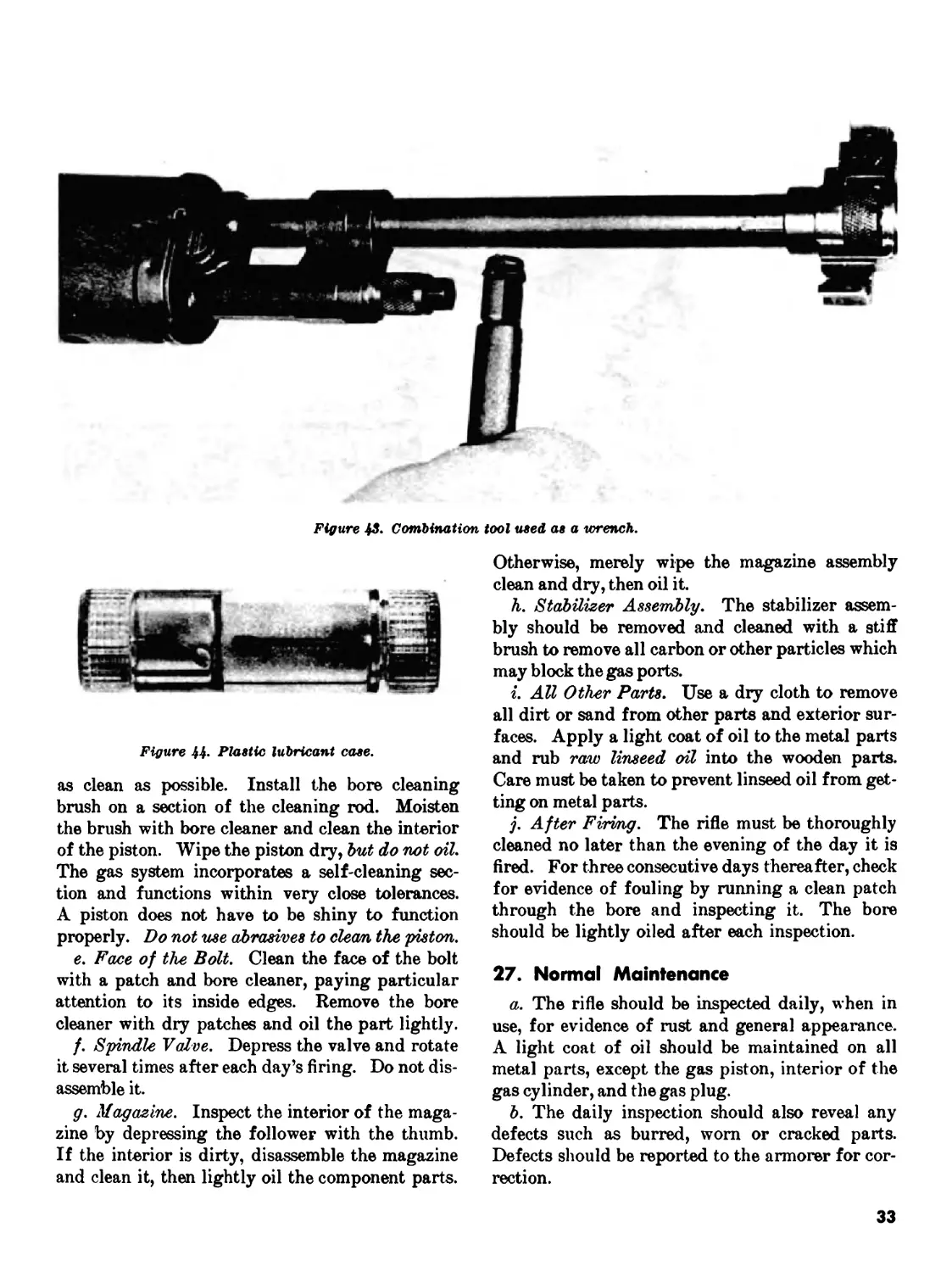
(2) The combination tool can be used as either
a 20° offset screwdriver or as a gas plug
wrench (figs. 42 and 43).
(a) The handle of the combination tool is
also used as the cleaning rod handle.
To do this, allow the cleaning rod ex-
tension of the tool to fall from the tool
handle so that it hangs perpendicular.
'Insure the M14 chamber brush Is used to prevent barrel dam-
age. The M14 brush Is one-half Inch shorter than the Ml cham-
ber brush.
31
Assemble the four sections of the clean-
ing rod and screw into the threaded
hole in the cleaning rod extension.
Either the bore brush or the cleaning
patch holder may be attached to the end
of the cleaning rod.
(b) The plastic lubricant case (fig. 44) is
closed with a screw cap which has a
stem (applicator) attached that is used
to apply oil drop by drop on one end.
The cap is fitted with a gasket to pre-
vent oil leakage. The other end has
another screw cap and contains rifle
grease.
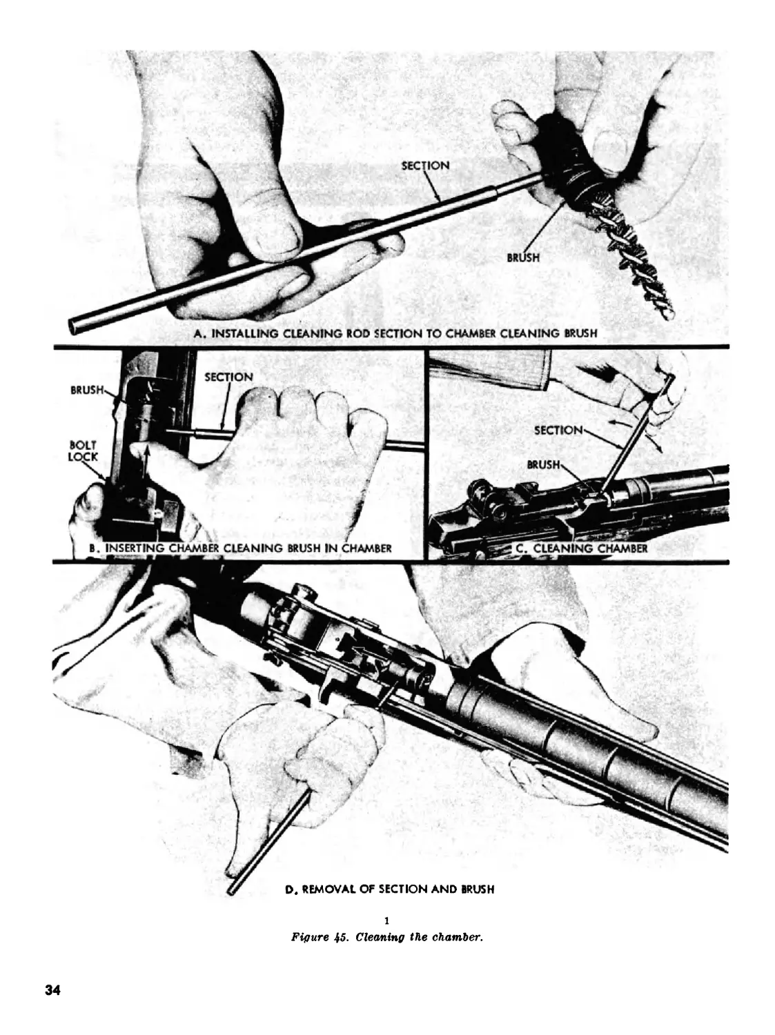
26. Cleaning the Rifle
a. Procedures for Cleaning Chamber а/nd Bore.
The rifle must be cleaned after it has been fired
because firing deposits primer fouling, powdc/
ashes, carbon and metal fouling. The ammuni-
tion has a noncorrosive primer which makes clean-
ing easier, but not less important. The primer
still leaves a deposit that may collect moisture and
promote rust if it is not removed. The procedures
for cleaning the chamber and bore are described in
figures 45 and 46. These procedures will insure
that the bore is cleaned evenly and will prevent
foreign matter from being pushed into the receiver
from the bore. Upon completion of firing, bore
cleaner should be applied for ease of further
ckaning.
b. Gas Cylinder Plug. Pour a small quantity
of bore cleaner in the plug, insert and rotate the
bore cleaning brush. Remove the brush, clean
and dry the plug with patches.
c. Gas Cylinder. Install the patch holder on a
section of the cleaning rod. Put two patches in
the holder, moisten them with bore cleaner and
swab the cylinder bore. Dry the cylinder bore
with clean patches. Use no abrasives in cleaning
the cylinder and do not oil the interior surfaces.
d. Gas Piston. Saturate patches with bore
cleaner and wipe the exterior surface of the piston.
COMBINATION TOOL
CONTAINING: 4 SECTIONS
1 BRUSH
1 HOLDER
Figure 41—Continued.
Figure 42- Combination tool used as a screwdriver.
32
Figure 43. Combination tool used as a wrench.
Figure 44- Plastic lubricant case.
as clean as possible. Install the bore cleaning
brush on a section of the cleaning rod. Moisten
the brush with bore cleaner and clean the interior
of the piston. Wipe the piston dry, but do not oil.
The gas system incorporates a self-cleaning sec-
tion and functions within very close tolerances.
A piston does not have to be shiny to function
properly. Do not use abrasives to clean the piston.
e. Face of the Bolt. Clean the face of the bolt
with a patch and bore cleaner, paying particular
attention to its inside edges. Remove the bore
cleaner with dry patches and oil the part lightly.
/. Spindle Valve. Depress the valve and rotate
it several times after each day’s firing. Do not dis-
assemble it.
g. Magazine. Inspect the interior of the maga-
zine by depressing the follower with the thumb.
If the interior is dirty, disassemble the magazine
and clean it, then lightly oil the component parts.
Otherwise, merely wipe the magazine assembly
clean and dry, then oil it.
h. Stabilizer Assembly. The stabilizer assem-
bly should be removed and cleaned with a stiff
brush to remove all carbon or other particles which
may block the gas ports.
i. All Other Parts. Use a dry cloth to remove
all dirt or sand from other parts and exterior sur-
faces. Apply a light coat of oil to the metal parts
and rub raw linseed oil into the wooden parts.
Care must be taken to prevent linseed oil from get-
ting on metal parts.
j. After Firing. The rifle must be thoroughly
cleaned no later than the evening of the day it is
fired. For three consecutive days thereafter, check
for evidence of fouling by running a clean patch
through the bore and inspecting it. The bore
should be lightly oiled after each inspection.
27. Normal Maintenance
a. The rifle should be inspected daily, when in
use, for evidence of rust and general appearance.
A light coat of oil should be maintained on all
metal parts, except the gas piston, interior of the
gas cylinder, and the gas plug.
b. The daily inspection should also reveal any
defects such as burred, worn or cracked parts.
Defects should be reported to the armorer for cor-
rection.
33
1
Figure 45. Cleaning the chamber.
34
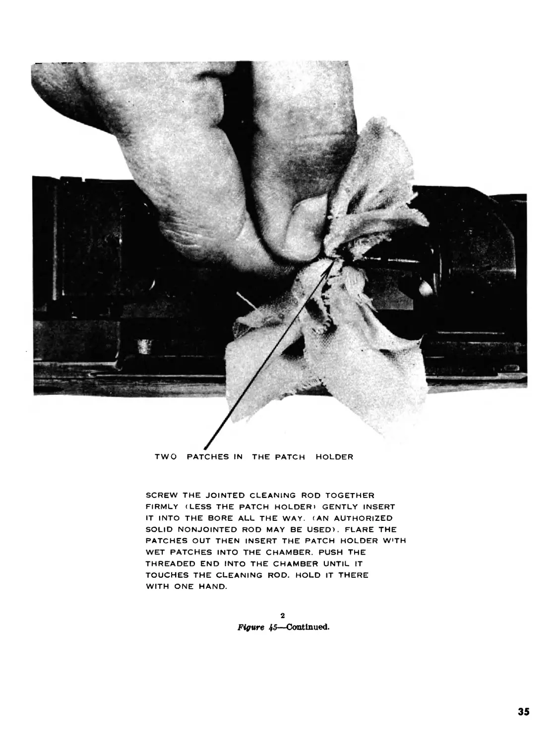
TWO PATCHES IN THE PATCH
HOLDER
SCREW THE JOINTED CLEANING ROD TOGETHER
FIRMLY (LESS THE PATCH HOLDER) GENTLY INSERT
IT INTO THE BORE ALL THE WAY. (AN AUTHORIZED
SOLID NONJOINTED ROD MAY BE USED). FLARE THE
PATCHES OUT THEN INSERT THE PATCH HOLDER W'TH
WET PATCHES INTO THE CHAMBER. PUSH THE
THREADED END INTO THE CHAMBER UNTIL IT
TOUCHES THE CLEANING ROD. HOLD IT THERE
WITH ONE HAND.
2
Figure 45—Continued.
35
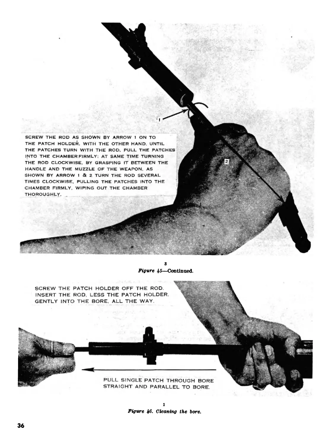
SCREW THE ROD AS SHOWN BY ARROW 1 ON TO
THE PATCH HOLDER. WITH THE OTHER HAND, UNTIL
THE PATCHES TURN WITH THE ROD. PULL THE PATCHES
INTO THE CHAMBER FIRMLY: AT SAME TIME TURNING
THE ROD CLOCKWISE. BY GRASPING IT BETWEEN THE
HANDLE AND THE MUZZLE OF THE WEAPON. AS
SHOWN BY ARROW I & 2 TURN THE ROD SEVERAL
TIMES CLOCKWISE, PULLING THE PATCHES INTO THE
CHAMBER FIRMLY, WIPING OUT THE CHAMBER
THOROUGHLY.
8
Figure 45—Continued.
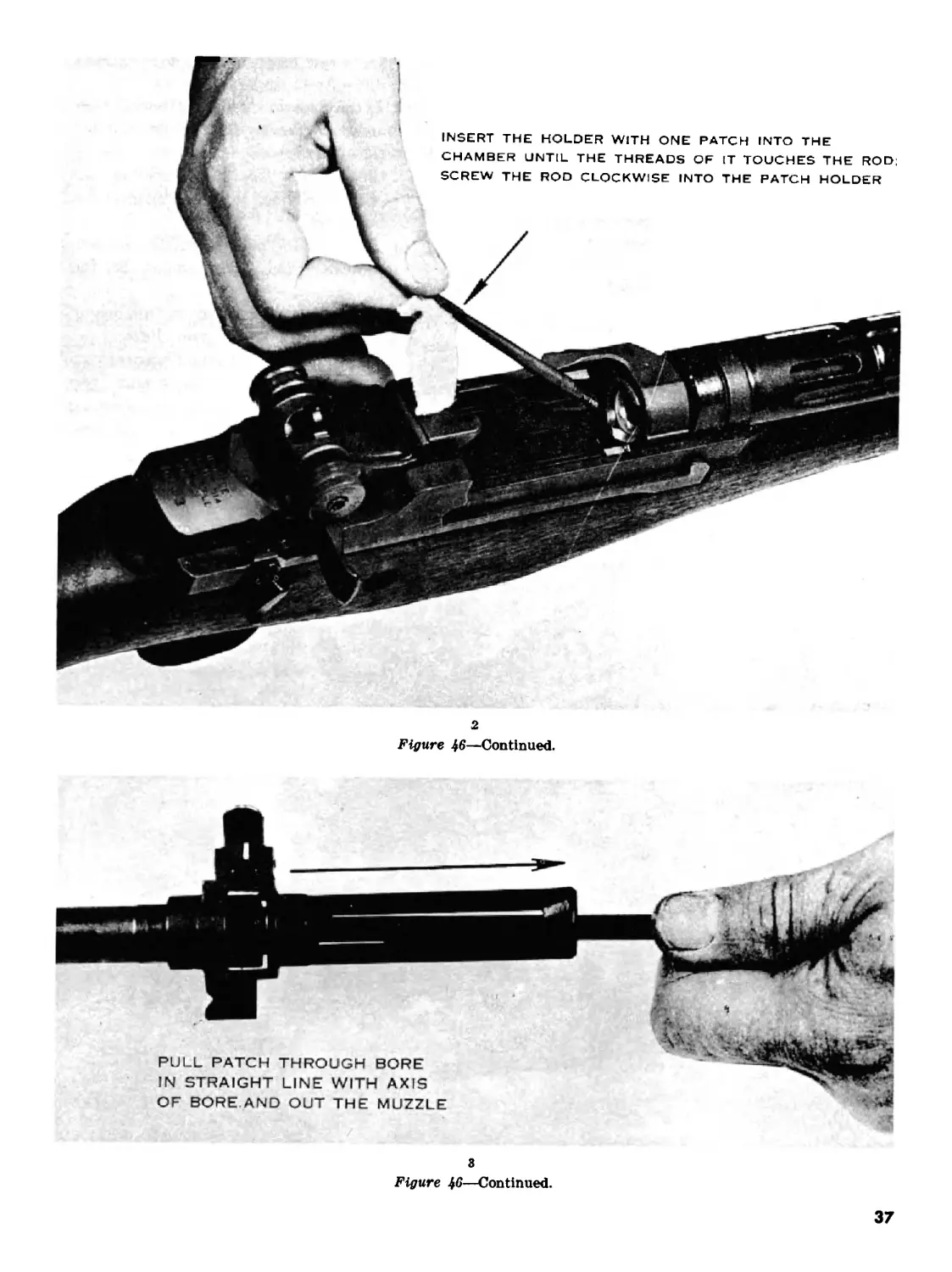
SCREW THE PATCH HOLDER OFF THE ROD.
INSERT THE ROD. LESS THE PATCH HOLDER.
GENTLY INTO THE BORE. ALL THE WAY.
PULL SINGLE PATCH THROUGH BORE
STRAIGHT AND PARALLEL TO BORE.
1
Figure 46. Cleaning the bore.
36
2
Figure 46—Continued.
8
Figure 46—Continued.
37
c. A muzzle plug should never be used on the
rifle. It causes moisture to collect in the bore form-
ing rust and creating a safety hazard.
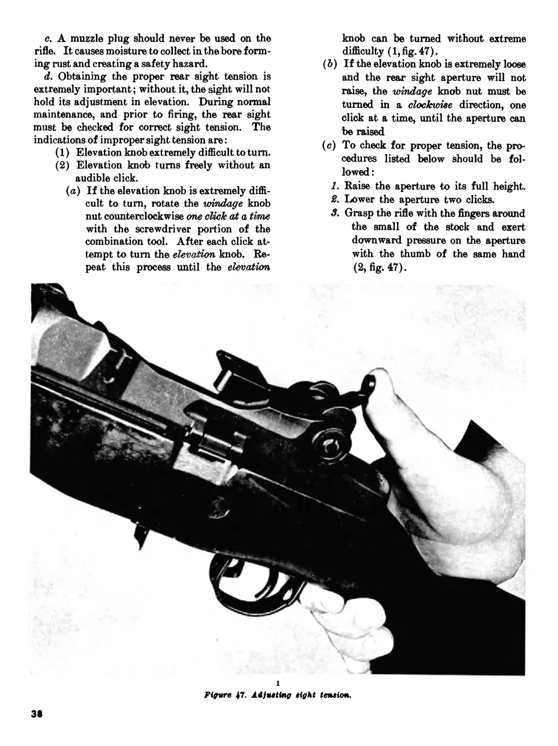
d. Obtaining the proper rear sight tension is
extremely important; without it, the sight will not
hold its adjustment in elevation. During normal
maintenance, and prior to firing, the rear sight
must be checked for correct sight tension. The
indications of improper sight tension are:
(1) Elevation knob extremely difficult to turn.
(2) Elevation knob turns freely without an
audible click.
(a) If the elevation knob is extremely diffi-
cult to turn, rotate the windage knob
nut counterclockwise one click ad a time
with the screwdriver portion of the
combination tool. After each click at-
tempt to turn the elevation knob. Re-
peat this process until the elevation
knob can be turned without extreme
difficulty (1, fig. 47).
(b) If the elevation knob is extremely loose
and the rear sight aperture will not
raise, the windage knob nut must be
turned in a clockwise direction, one
click at a time, until the aperture can
be raised
(<?) To check for proper tension, the pro-
cedures listed below should be fol-
lowed:
1. Raise the aperture to its full height.
£. Lower the aperture two clicks.
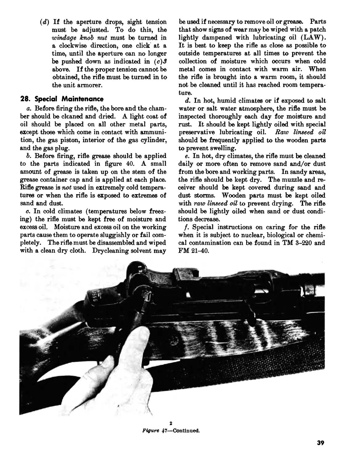
3. Grasp the rifle with the fingers around
the small of the stock and exert
downward pressure on the aperture
with the thumb of the same hand
(2, fig. 47).
i
Figure 47. Adjusting eight tension.
38
(d) If the aperture drops, sight tension
must be adjusted. To do this, the
windage knob nut must be turned in
a clockwise direction, one click at a
time, until the aperture can no longer
be pushed down as indicated in (c}3
above. If the proper tension cannot be
obtained, the rifle must be turned in to
the unit armorer.
28. Special Maintenance
a. Before firing the rifle, the bore and the cham-
ber should be cleaned and dried. A light coat of
oil should be placed on all other metal parts,
except those which come in contact with ammuni-
tion, the gas piston, interior of the gas cylinder,
and the gas plug.
b. Before firing, rifle grease should be applied
to the parts indicated in figure 40. A small
amount of grease is taken up on the stem of the
grease container cap and is applied at each place.
Rifle grease is not used in extremely cold tempera-
tures or when the rifle is exposed to extremes of
sand and dust.
c. In cold climates (temperatures below freez-
ing) the rifle must be kept free of moisture and
excess oil. Moisture and excess oil on the working
parts cause them to operate sluggishly or fail com-
pletely. The rifle must be disassembled and wiped
with a clean dry cloth. Drycleaning solvent may
be used if necessary to remove oil or grease. Parts
that show signs of wear may be wiped with a patch
lightly dampened with lubricating oil (LAW).
It is best to keep the rifle as close as possible to
outside temperatures at all times to prevent the
collection of moisture which occurs when cold
metal comes in contact with warm air. When
the rifle is brought into a warm room, it should
not be cleaned until it has reached room tempera-
ture.
d. In hot, humid climates or if exposed to salt
water or salt water atmosphere, the rifle must be
inspected thoroughly each day for moisture and
rust. It should be kept lightly oiled with special
preservative lubricating oil. Raw linseed oil
should be frequently applied to the wooden parts
to prevent swelling.
e. In hot, dry climates, the rifle must be cleaned
daily or more often to remove sand and/or dust
from the bore and working parts. In sandy areas,
the rifle should be kept dry. The muzzle and re-
ceiver should be kept covered during sand and
dust storms. Wooden parts must be kept oiled
with raw linseed oil to prevent drying. The rifle
should be lightly oiled when sand or dust condi-
tions decrease.
/. Special instructions on caring for the rifle
when it is subject to nuclear, biological or chemi-
cal contamination can be found in TM 3-220 and
FM 21-40.
2
Figure 47—Continued.
39
CHAPTER 6
AMMUNITION
29. General
The M14 rifle fires several types of ammunition.
The rifleman should be able to recognize them and
know which type is best for certain targets. He
should also know how to care for the ammunition.
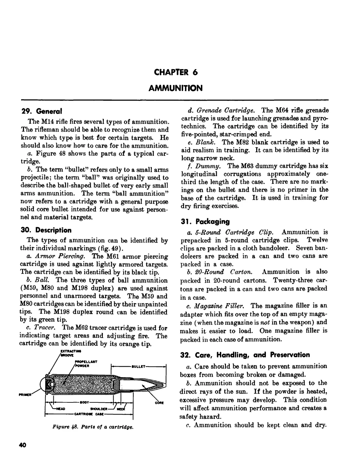
a. Figure 48 shows the parts of a typical car-
tridge.
b. The term “bullet” refers only to a small arms
projectile; the term “ball” was originally used to
describe the ball-shaped bullet of very early small
arms ammunition. The term “ball ammunition”
now refers to a cartridge with a general purpose
solid core bullet intended for use against person-
nel and material targets.
30. Description
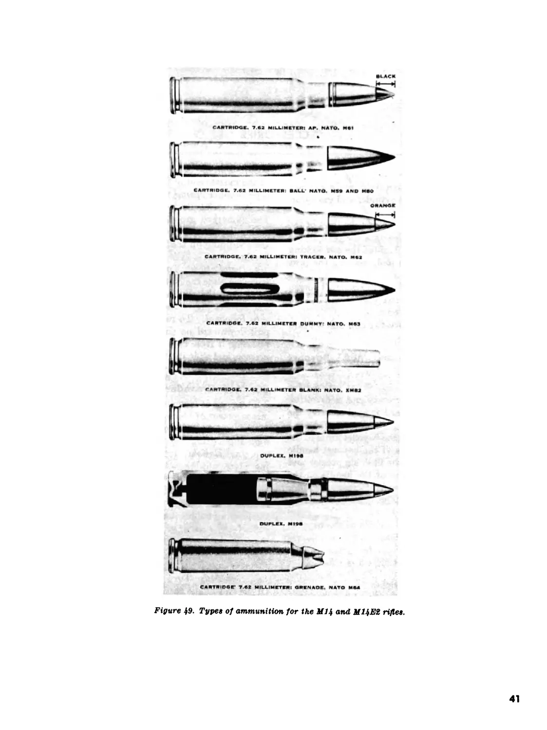
The types of ammunition can be identified by
their individual markings (fig. 49).
a. Armor Piercing. The M61 armor piercing
cartridge is used against lightly armored targets.
The cartridge can be identified by its black tip.
b. Ball. The three types of ball ammunition
(M59, M80 and M198 duplex) are used against
personnel and unarmored targets. The M59 and
M80 cartridges can be identified by their unpainted
tips. The M198 duplex round can be identified
by its green tip.
с. Tracer. The M62 tracer cartridge is used for
indicating target areas and adjusting fire. The
cartridge can be identified by its orange tip.
Figure Parts of a cartridge.
d. Grenade Cartridge. The M64 rifle grenade
cartridge is used for launching grenades and pyro-
technics. The cartridge can be identified by its
five-pointed, star-crimped end.
e. Blank. The M82 blank cartridge is used to
aid realism in training. It can be identified by its
long narrow neck.
f. Dummy. The M63 dummy cartridge has six
longitudinal corrugations approximately one-
third the length of the case. There are no mark-
ings on the bullet and there is no primer in the
base of the cartridge. It is used in training for
dry firing exercises.
31. Packaging
a. 5-Rov/nd Cartridge Clip. Ammunition is
prepacked in 5-round cartridge clips. Twelve
clips are packed in a cloth bandoleer. Seven ban-
doleers are packed in a can and two cans are
packed in a case.
b. 20-Round Carton. Ammunition is also
packed in 20-round cartons. Twenty-three car-
tons are packed in a can and two cans are packed
in a case.
c. Magazine Filler. The magazine filler is an
adapter which fits over the top of an empty maga-
zine (when the magazine is not in the weapon) and
makes it easier to load. One magazine filler is
packed in each case of ammunition.
32. Care, Handling, and Preservation
a. Care should be taken to prevent ammunition
boxes from becoming broken or damaged.
b. Ammunition should not be exposed to the
direct rays of the sun. If the powder is heated,
excessive pressure may develop. This condition
will affect ammunition performance and creates a
safety hazard.
c. Ammunition should be kept clean and dry.
40
CARTRIDGE. 7.62 MILLIMETER: AF. NATO. MSI
CARTRIDGE. 7.42 MILLIMETER OLANKI NATO. KM62
OU₽L<X. MISS
DUPLEX. MISS
Figure 49. Types of ammunition for the Ml4 and МЦЕ2 rifles.
41
CHAPTER 7
ACCESSORIES
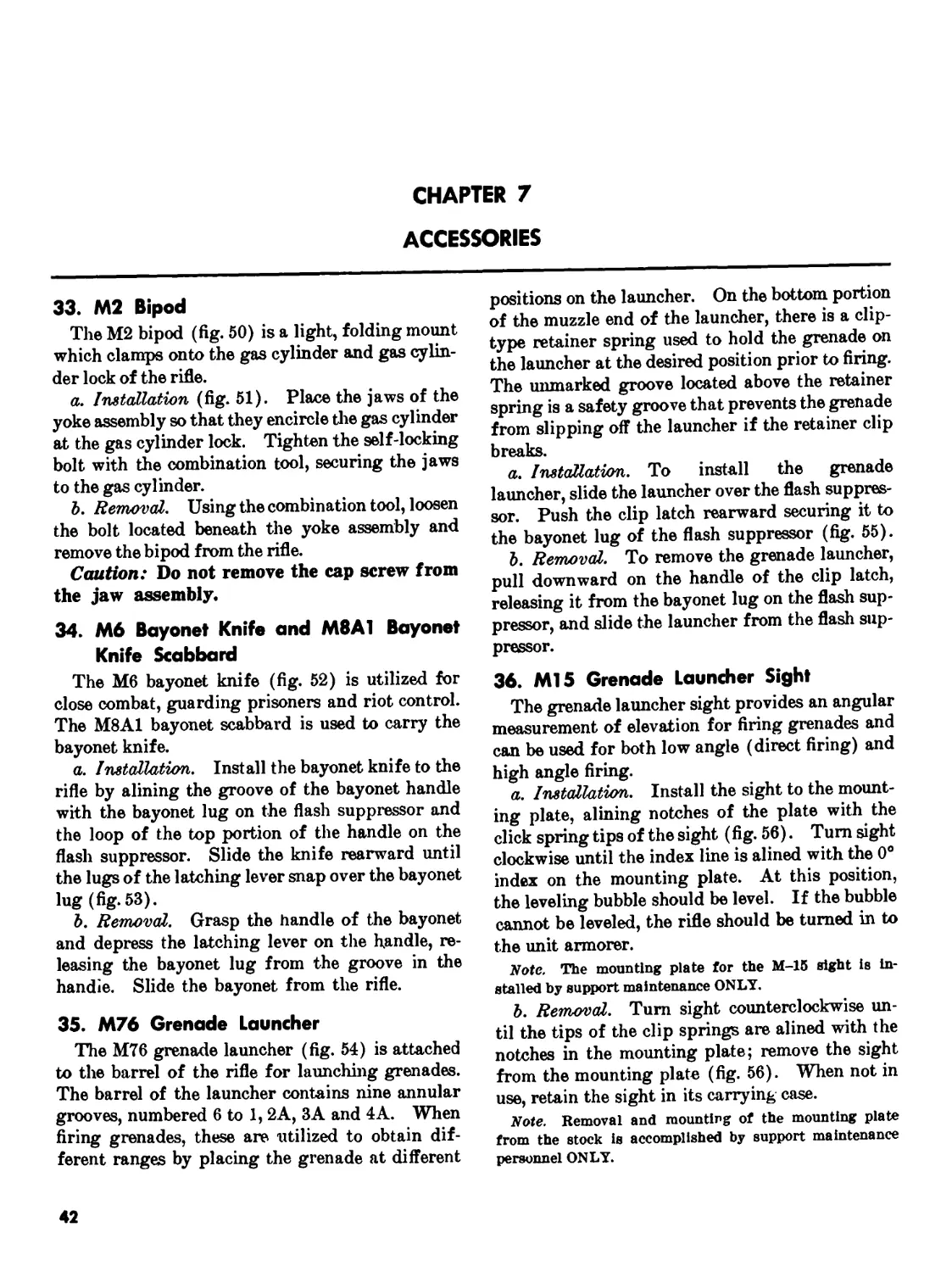
33. М2 Bipod
The М2 bipod (fig. 50) is a light, folding mount
which clamps onto the gas cylinder and gas cylin-
der lock of the rifle.
a. Installation (fig. 51). Place the jaws of the
yoke assembly so that they encircle the gas cylinder
at the gas cylinder lock. Tighten the self-locking
bolt with the combination tool, securing the jaws
to the gas cylinder.
b. Removal. Using the combination tool, loosen
the bolt located beneath the yoke assembly and
remove the bipod from the rifle.
Caution: Do not remove the cap screw from
the jaw assembly.
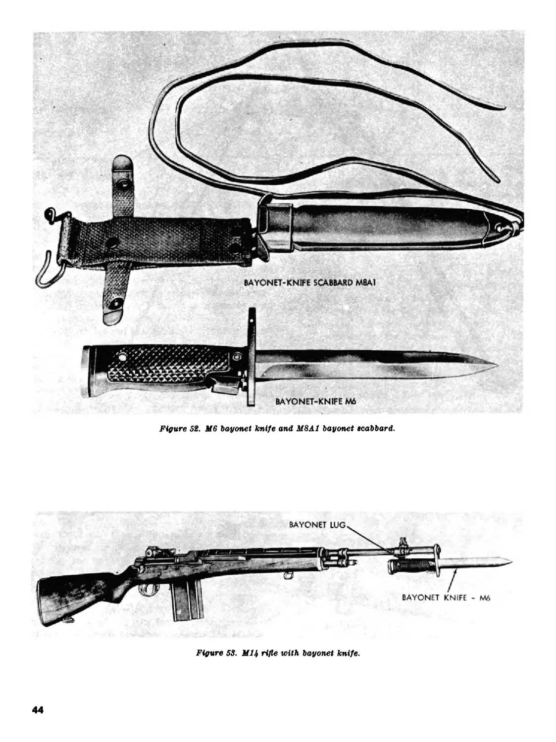
34. M6 Bayonet Knife and M8A1 Bayonet
Knife Scabbard
The M6 bayonet knife (fig. 52) is utilized for
close combat, guarding prisoners and riot control.
The M8A1 bayonet scabbard is used to carry the
bayonet knife.
a. Installation. Install the bayonet knife to the
rifle by alining the groove of the bayonet handle
with the bayonet lug on the flash suppressor and
the loop of the top portion of the handle on the
flash suppressor. Slide the knife rearward until
the lugs of the latching lever snap over the bayonet
lug (fig. 53).
b. Removal. Grasp the handle of the bayonet
and depress the latching lever on the handle, re-
leasing the bayonet lug from the groove in the
handle. Slide the bayonet from the rifle.
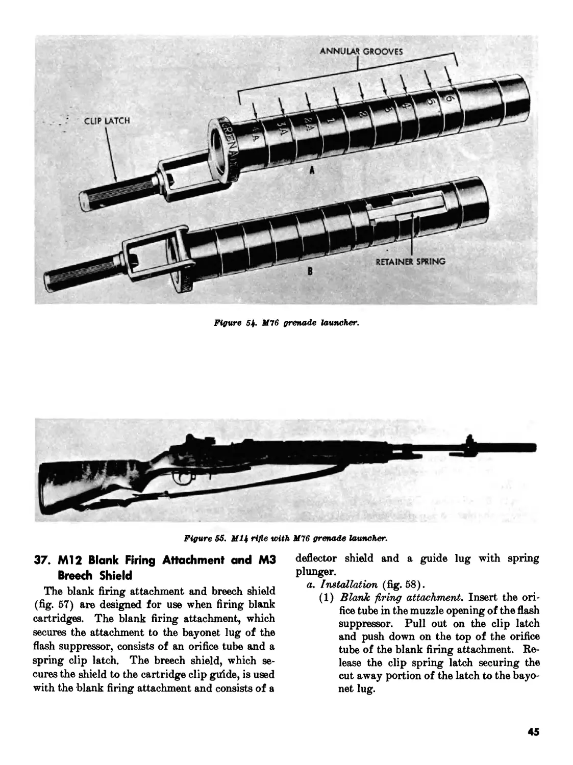
35. M76 Grenade Launcher
The M76 grenade launcher (fig. 54) is attached
to the barrel of the rifle for launching grenades.
The barrel of the launcher contains nine annular
grooves, numbered 6 to 1, 2A, ЗА and 4A. When
firing grenades, these are utilized to obtain dif-
ferent ranges by placing the grenade at different
positions on the launcher. On the bottom portion
of the muzzle end of the launcher, there is a clip-
type retainer spring used to hold the grenade on
the launcher at the desired position prior to firing.
The unmarked groove located above the retainer
spring is a safety groove that prevents the grenade
from slipping off the launcher if the retainer clip
breaks.
a. Installation. To install the grenade
launcher, slide the launcher over the flash suppres-
sor. Push the clip latch rearward securing it to
the bayonet lug of the flash suppressor (fig. 55).
b. Removal. To remove the grenade launcher,
pull downward on the handle of the clip latch,
releasing it from the bayonet lug on the flash sup-
pressor, and slide the launcher from the flash sup-
pressor.
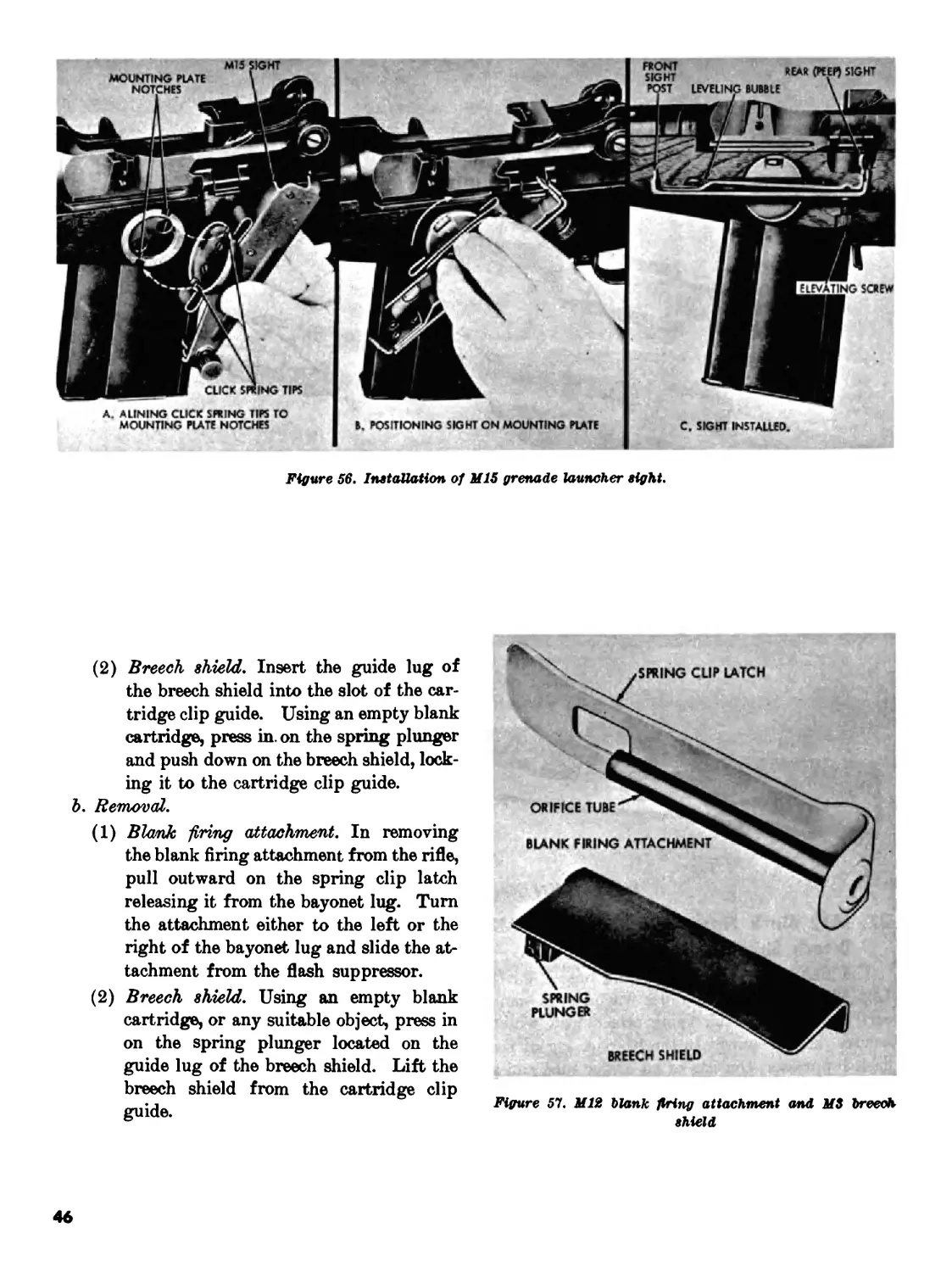
36. Ml 5 Grenade Launcher Sight
The grenade launcher sight provides an angular
measurement of elevation for firing grenades and
can be used for both low angle (direct firing) and
high angle firing.
a. Installation. Install the sight to the mount-
ing plate, alining notches of the plate with the
click spring tips of the sight (fig. 56). Turn sight
clockwise until the index line is alined with the 0°
index on the mounting plate. At this position,
the leveling bubble should be level. If the bubble
cannot be leveled, the rifle should be turned in to
the unit armorer.
Note. The mounting plate for the M-15 sight is in-
stalled by support maintenance ONLY.
b. Removal. Turn sight counterclockwise un-
til the tips of the clip springs are alined with the
notches in the mounting plate; remove the sight
from the mounting plate (fig. 56). When not in
use, retain the sight in its carrying case.
Note. Removal and mounting of the mounting plate
from the stock is accomplished by support maintenance
personnel ONLY.
42
JAW
Figure 51. Installation of М2 bipod.
43
Figure 52. M6 bayonet knife and M8A.1 bayonet scabbard.
BAYONET LUG
BAYONET KNIFE - M6
Figure 53. МЦ rifle with bayonet knife.
44
Figure 54. M76 grenade launcher.
Figure 55. M14 rifle with M76 grenade launcher.
37. Ml 2 Blank Firing Attachment and М3
Breech Shield
The blank firing attachment and breech shield
(fig. 57) are designed for use when firing blank
cartridges. The blank firing attachment, which
secures the attachment to the bayonet lug of the
flash suppressor, consists of an orifice tube and a
spring clip latch. The breech shield, which se-
cures the shield to the cartridge clip guide, is used
with the blank firing attachment and consists of a
deflector shield and a guide lug with spring
plunger.
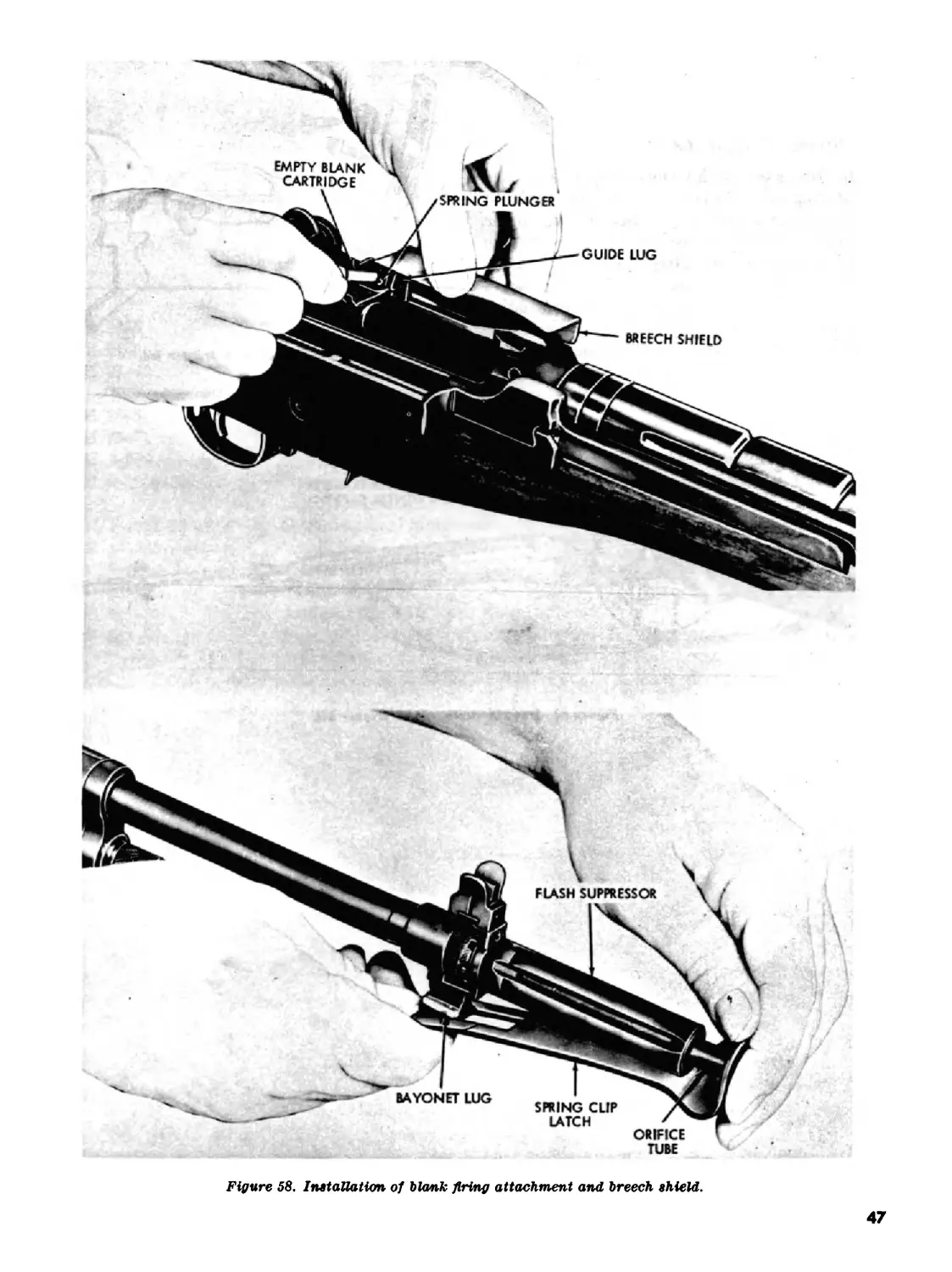
a. Installation (fig. 58).
(1) Blank -firing attachment. Insert the ori-
fice tube in the muzzle opening of the flash
suppressor. Pull out on the clip latch
and push down on the top of the orifice
tube of the blank firing attachment. Re-
lease the clip spring latch securing the
cut away portion of the latch to the bayo-
net lug.
45
Figure 56. Installation of MIS grenade launcher eight.
(2) Breech shield. Insert the guide lug of
the breech shield into the slot of the car-
tridge clip guide. Using an empty blank
cartridge, press in. on the spring plunger
and push down on the breech shield, lock-
ing it to the cartridge clip guide.
b. Removal.
(1) Blank firing attachment. In removing
the blank firing attachment from the rifle,
pull outward on the spring clip latch
releasing it from the bayonet lug. Turn
the attachment either to the left or the
right of the bayonet lug and slide the at-
tachment from the flash suppressor.
(2) Breech shield. Using an empty blank
cartridge, or any suitable object, press in
on the spring plunger located on the
guide lug of the breech shield. Lift the
breech shield from the cartridge clip
guide.
Figure 51. M12 blank firing attachment and MS breech
shield
46
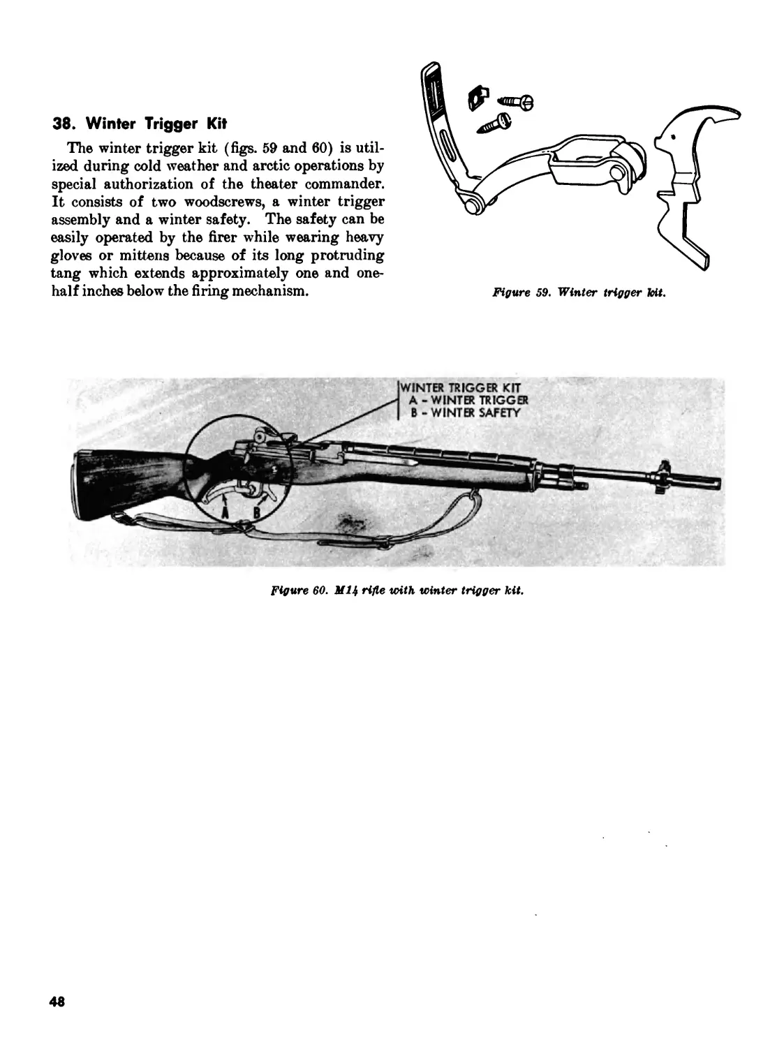
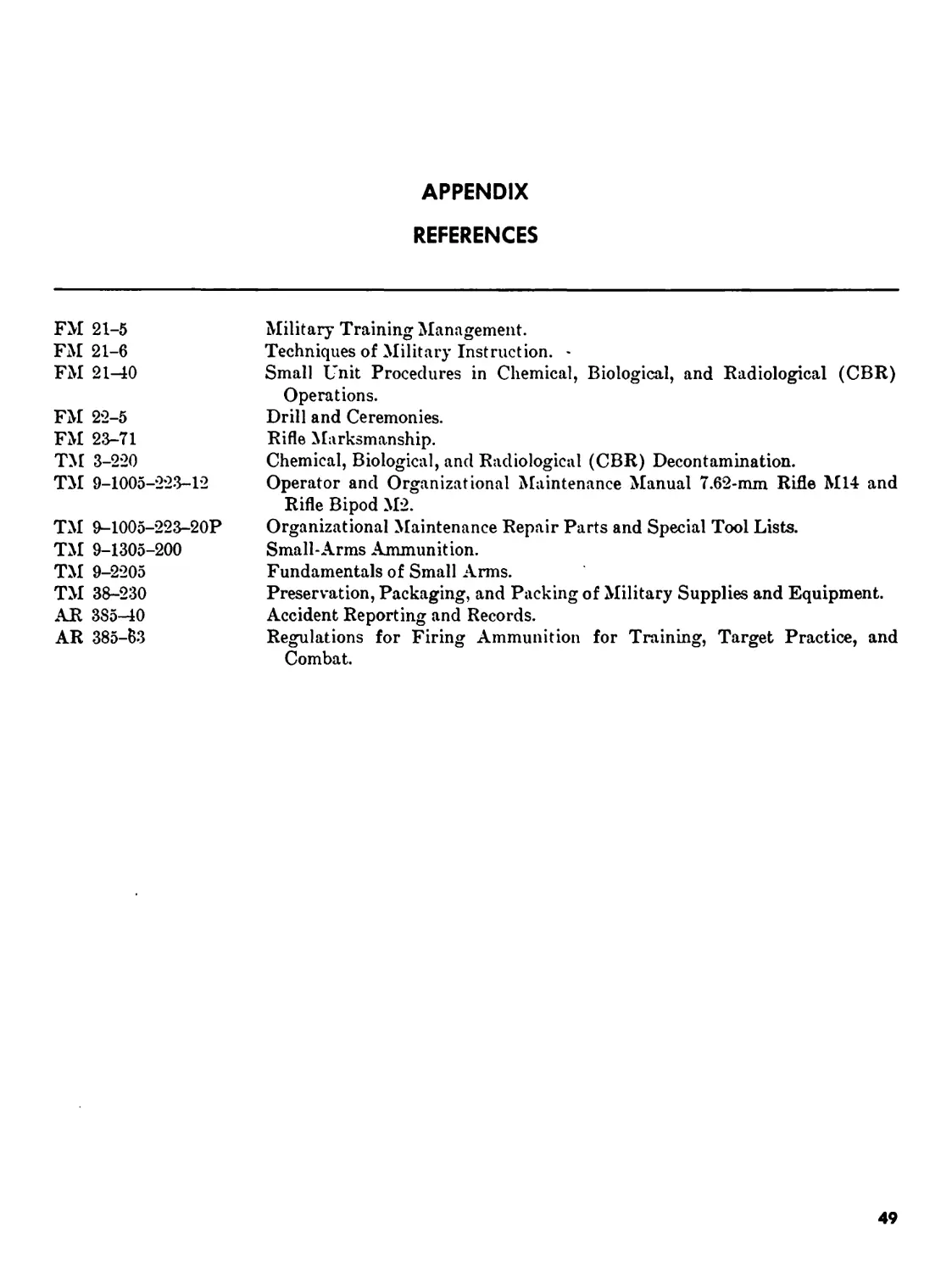
38. Winter Trigger Kit
The winter trigger kit (figs. 59 and 60) is util-
ized during cold weather and arctic operations by
special authorization of the theater commander.
It consists of two woodscrews, a winter trigger
assembly and a winter safety. The safety can be
easily operated by the firer while wearing heavy
gloves or mittens because of its long protruding
tang which extends approximately one and one-
half inches below the firing mechanism.
Figure 59. Winter trigger kit.
Figure 60. МЦ rifle with winter trigger kit.
48
APPENDIX
REFERENCES
FM 21-5 FM 21-6 FM 21-10 Military Training Management. Techniques of Military Instruction. - Small Unit Procedures in Chemical, Biological, and Radiological (CBR) Operations.
FM 22-5 FM 23-71 TM 3-220 TM 9-1005-223-12 Drill and Ceremonies. Rifle Marksmanship. Chemical, Biological, and Radiological (CBR) Decontamination. Operator and Organizational Maintenance Manual 7.62-mm Rifle M14 and Rifle Bipod М2.
TM 9-1005-223-20P TM 9-1305-200 TM 9-2205 TM 38-230 AR 385-40 AR 385-63 Organizational Maintenance Repair Parts and Special Tool Lists. Small-Arms Ammunition. Fundamentals of Small Arms. Preservation, Packaging, and Packing of Military Supplies and Equipment. Accident Reporting and Records. Regulations for Firing Ammunition for Training, Target Practice, and Combat.
49
By Order of the Secretary of the Army:
Official:
J. C. LAMBERT,
Major General, United States Army,
The Adjutant General.
HAROLD K. JOHNSON,
General, United States Army,
Chief of Staff.
Distribution:
Active Army:
DCSPER (2) LOGCOMD (1) MFSS (1)
DCSPR (2) USACDC (2) USAOC&S (1)
ACSI (2) Armies (25) USAQMS (1)
DSCLOG (2) Corps (3) USASCS (1)
DCSOPS (2) Div (10 USACHS (1)
CORO (2) Div Arty (5) US AES (1)
CRD (1) Bde (5) USATSCH (1)
CO A (1) Regt (5) USACMLCS (1)
CINFO (1) Gp (1) USASESCS (1)
TIG (1) BG (5) USMA (2)
TJAGSA (1) CC (5) Svc Colleges (5)
CNGB (2) Bn (5) Mil Msn (1)
ACSFOR (2) Co/Btry (5) USATC (10) except
USCONARC (5) Br Svc Sch (5) except USATC Inf (25)
ARADCOM (2) USAMPS (1)
ARADCOM Rgn (1)
NG: State AG (3); units—same as Active Army except allowance is four copies to each unit
US AR: Units—same as Active Army except allowance is two copies to each unit.
For explanation of abbreviations used, see AR 320-50.
U.S. GOVERNMENT PRINTING OFFICE: 1965 О—77Э-070
50