/
Tags: weapons military affairs patent
Year: 1909
Text
W. J. WHITING.
AUTOMATIC PISTOL AND RIFLE.
APPLICATION TILED APK. 8 1 BOB.
944,930.
Patented Dec. 28,1909.
3 SHEETS-SHEET 1.
WITNESSES
IN V E N T 0
AHNKW а ОЯЛИШ И- PHOTO lintOOAASWML WAOHWGID* 0
944,930.
W. J. WHITING.
AUTOMATIC PISTOL AND RIFLE.
APPLICATION FILED APB. 9, 1909.
Patented Dec. 28,1909.
3 SHEETS-SHEET 2.
WITNESSES
944,930.
W. J. WHITING.
AUTOMATIC PISTOL AND KIFLE.
APPLICATION FILED APB. О, 1308.
Patented Dec. 28,1909.
3 SHEETS—SHEET 3.
WITNESSES
INVENTOR^O^/t
UNITED STATES PATENT OFFICE.
WILLIAM JOHN WHITING, OF HANDSWORTH, NEAR BIRMINGHAM, ENGLAND,
AUTOMATIC PISTOL AND RIFLE.
944,930. Specification of Letters Patent. Patented Dec. 28, 1909.
Application filed April 9, 1909. Serial No. 488,916.
5
10
15
20
25
30
35
40
45
50
55
To all whom it may concern:
Be it known that I, William John Whit-
ing, a subject of the King of Great Britain,
residing at 111 Antrobus road, Ilandsworth,
near Birmingham, England, director of
public company, have invented certain new
and useful Improvements in Automatic Pis-
tols and Rifles, of which the following is a
specification.
This invention has reference to automatic
hand fire-arms (including pistols and rifles)
of the reciprocating breech-block or breech-
slide type, and has for its object, to provide
improved means for automatically arrest-
ing and locking the breech-block or breech
slide in its open position after the last car-
tridge from the magazine has been dis-
charged, so as to afford an indication to the
shooter that the magazine of the pistol or
arm is empty. The arrangements that have
hitherto been devised and used for this pur-
pose have been dependent upon the magazine
spring, which, after the discharge of the last
cartridge, actuates a locking limb, slide or
stop and moves the same into such engage-
ment with the breech slide that the latter is
prevented from closing. But according to
the improved arrangement which constitutes
the present invention, so long as there is a
cartridge remaining in the magazine, the
magazine spring is made to act, through the
said cartridge, for holding the breech-slide
latch or locking device out of action, or in
an inoperative position, whereas after the
last cartridge has been loaded into the bar-
rel-chamber, the magazine spring ceases to
influence the said latch but the latter is then
acted upon solely by another and weaker
spring which is normally overpowered by
the said magazine spring, so that on the
breech slide recoiling when the last cartridge
is fired, the latch is shifted into an operative
position in which it engages with and pre-
vents the return of the said slide. And when
the empty magazine is replaced by a fully or
partially-charged one, the cartridges in the
latter again make connection between the
magazine-spring and the latch so that after
the latter has been disengaged and the
breech-slide allowed to close, the said maga-
zine spring again over-powers the weaker
latch-engaging spring and functions to re-
tain the said latch in its inoperative posi-
tion for so long as a cartridge remains in
the magazine to transmit the effort of the
said magazine-spring to the latch.
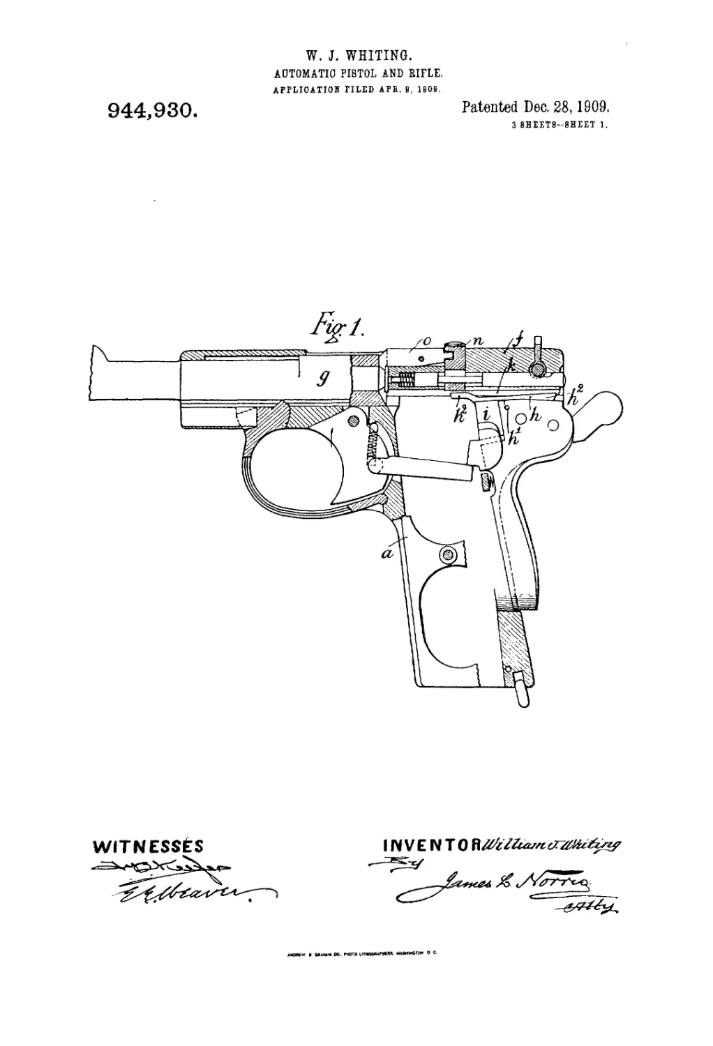
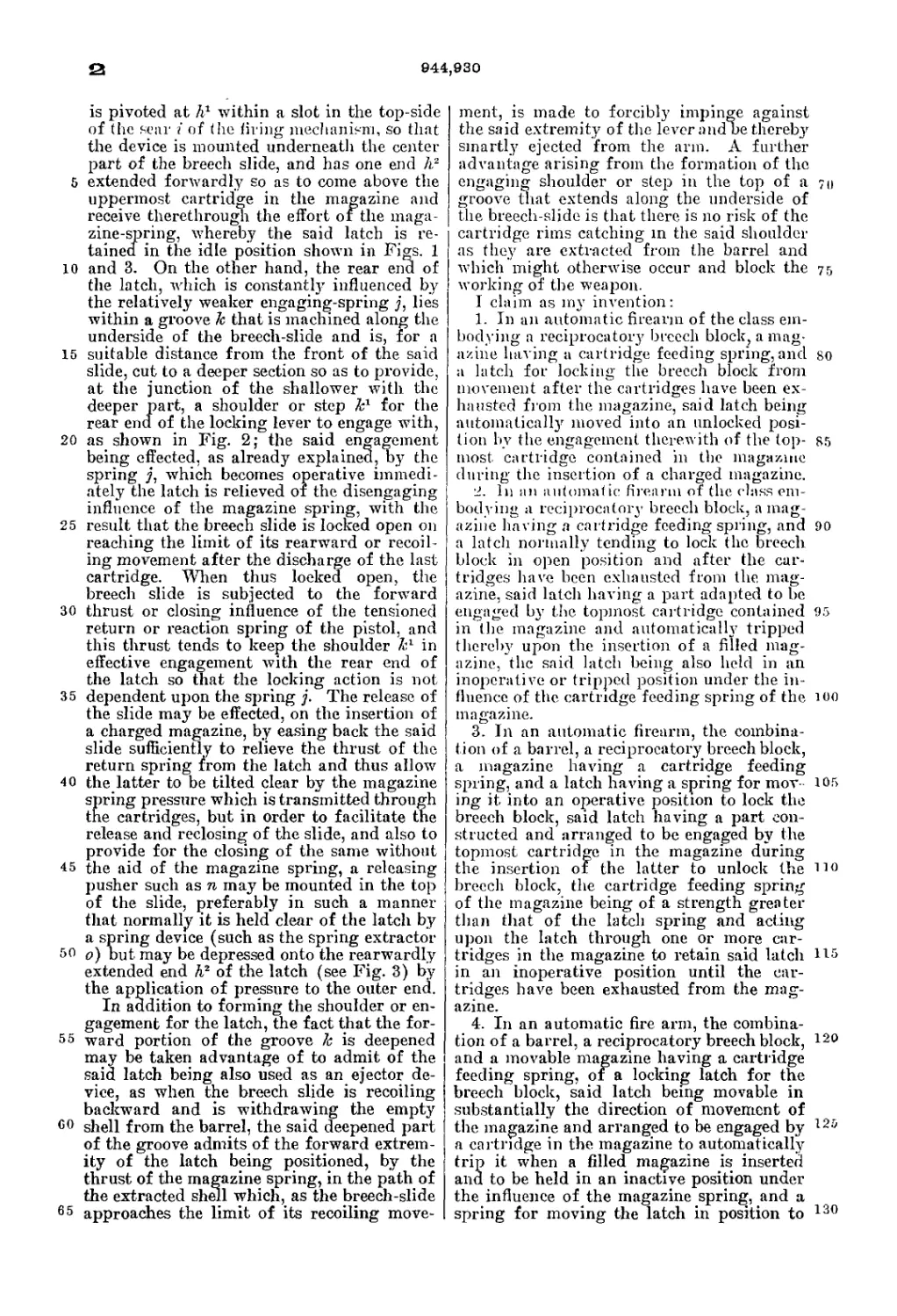
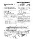
Figure 1 of the said drawings represents
the pistol in longitudinal vertical section
with the parts in the positions they assume
when the breech-slide is closed and when 60
the magazine contains cartridges for trans-
mitting the effort of the magazine spring to
hold the breech-slide latch out of action.
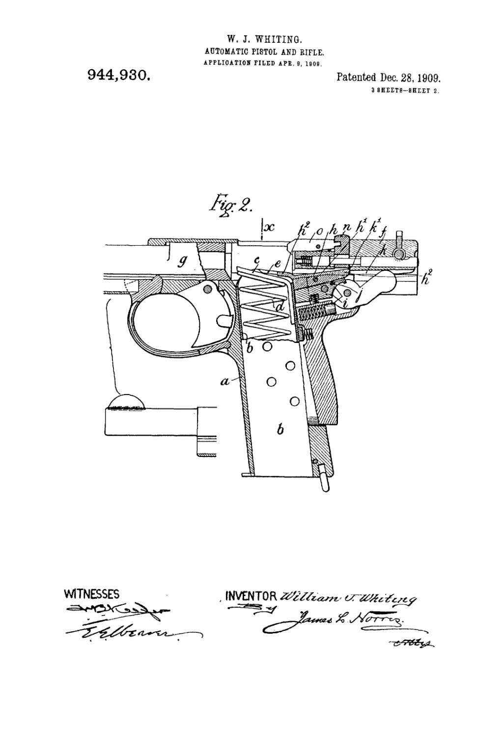
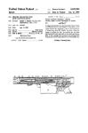
Fig. 2 is a similar view but shows how the
breech-slide is locked open by the latch de- 65
vice after the discharge of the last cartridge
and also shows how the spring-lifted maga-
zine platform is stopped or held clear of the
said latch so that the latter is influenced
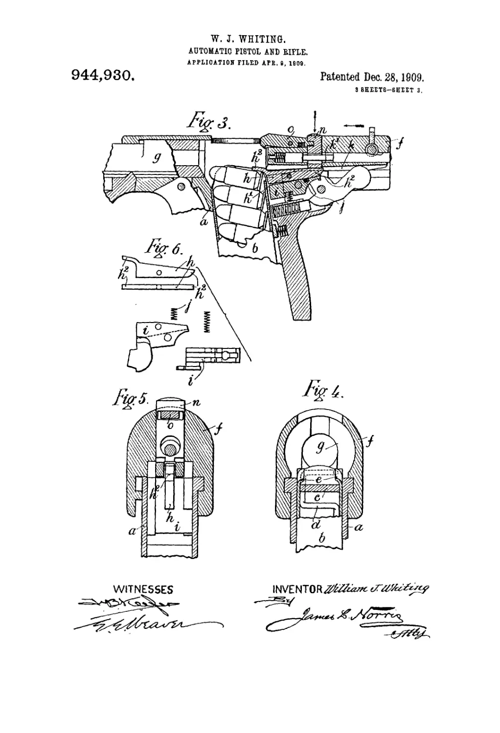
only by its engaging spring. Fig. 3 is a 70
view illustrating how the latch is disen-
gaged to permit of the closing of the bolt
after the empty magazine is replaced by a
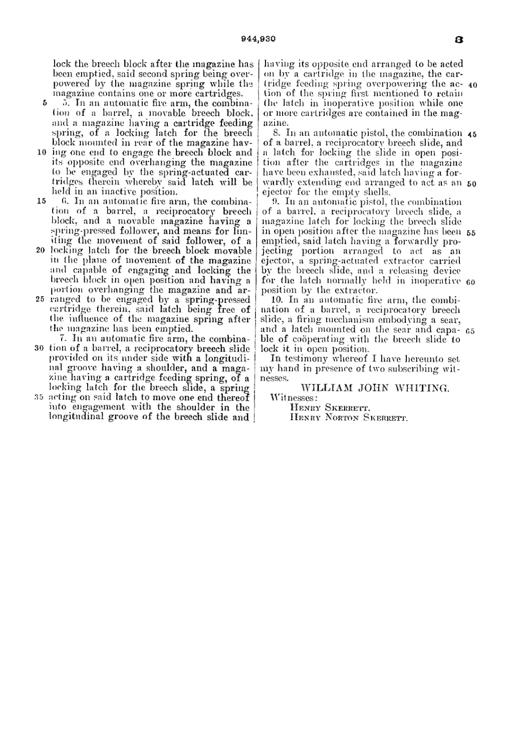
fully or partially charged one. Fig. 4 is a
sectional view, upon an enlarged scale, of a 75
part of the pistol, showing more clearly the
stops which determine the position of the
spring-lifted platform when the magazine is
empty and prevent the latch being in any
way influenced by the said spring. Fig. 5 is 80
another sectional view on the same scale as
Fig. 4, but taken on the dotted line x Fig. 2
and showing the engaging latch in end ele-
vation. Fig. G shows the latch and the part
on which it is mounted separately. 85
The same letters of reference indicate cor-
responding parts in the several figures of the
drawings.
The handle part a of the frame of the
pistol is of substantially the ordinary con- 90
struction and is adapted to receive an ordi-
nary magazine Ъ, which is fitted internally
with a platform c and a platform lifting
spring a. The upper open end of the said
magazine is also formed, on its opposite 95
sides, with the usual inwardly overhanging
lips e (see Figs. 2 and 4) against which the
upper cartridge in the magazine is made to
take its bearing and be thereby held in the
proper position for insuring that same shall 100
be pushed endwise out of the magazine and
loaded into the barrel g of the pistol, by the
breech slide f during its return or closing
movement. These lips also serve as stops
against which the magazine platform is 105
lifted (see Fig. 2) after the loading of the
last cartridge into the barrel and which pre-
vent the magazine spring from influencing
the breech-slide latch when the magazine is
empty. The said breech slide latch is marked no
A., and consists, in the particular arrange-
ment shown, of a rocking limb or lever which
044,930
5
10
15
20
25
30
35
40
45
50
55
CO
65
is pivoted at Л1 within a slot in the top-side
of (he sear i of the tiring mechanism, so that
the device is mounted underneath the center
part of the breech slide, and has one end №
extended forwardly so as to come above the
uppermost cartridge in the magazine and
receive therethrough the effort of the maga-
zine-spring, whereby the said latch is re-
tained in the idle position shown in Figs. 1
and 3. On the other hand, the rear end of
the latch, which is constantly influenced by
the relatively weaker engaging-spring j, lies
within a groove 1c that is machined along the
underside of the breech-slide and is, for a
suitable distance from the front of the said
slide, cut to a deeper section so as to provide,
at the junction of the shallower with the
deeper part, a shoulder or step k1 for the
rear end of the locking lever to engage with,
as shown in Fig. 2; the said engagement
being effected, as already explained, by the
spring y, which becomes operative immedi-
ately the latch is relieved of the disengaging
influence of the magazine spring, with the
result that the breech slide is locked open on
reaching the limit of its rearward or recoil-
ing movement after the discharge of the last
cartridge. When thus locked open, the
breech slide is subjected to the forward
thrust or closing influence of the tensioned
return or reaction spring of the pistol, and
this thrust tends to keep the shoulder in
effective engagement with the rear end of
the latch so that the locking action is not
dependent upon the spring j. The release of
the slide may be effected, on the insertion of
a charged magazine, by easing back the said
slide sufficiently to relieve the thrust of the
return spring from the latch and thus allow
the latter to be tilted clear by the magazine
spring pressure which is transmitted through
the cartridges, but in order to facilitate the
release and reclosing of the slide, and also to
provide for the closing of the same without
the aid of the magazine spring, a releasing
pusher such as n may be mounted in the top
of the slide, preferably in such a manner
that normally it is held clear of the latch by
a spring device (such as the spring extractor
o) but may be depressed onto the rearwardly
extended end Л2 of the latch (see Fig. 3) by
the application of pressure to the outer end.
In addition to forming the shoulder or en-
gagement for the latch, the fact that the for-
ward portion of the groove к is deepened
may be taken advantage of to admit of the
said latch being also used as an ejector de-
vice, as when the breech slide is recoiling
backward and is withdrawing the empty
shell from the barrel, the said deepened part
of the groove admits of the forward extrem-
ity of the latch being positioned, by the
thrust of the magazine spring, in the path of
the extracted shell which, as the breech-slide
approaches the limit of its recoiling move-
ment, is made to forcibly impinge against
the said extremity of the lever andoe thereby
smartly ejected from the arm. A further
advantage arising from the formation of the
engaging shoulder or step in the top of a 70
groove that extends along the underside of
the breech-slide is that there is no risk of the
cartridge rims catching in the said shoulder
as they are extracted from the barrel and
which might otherwise occur and block the 75
working of the weapon.
I claim as my invention:
1. In an automatic firearm of the class em-
bodying a reciprocatory breech block, a mag-
azine hal ing a cartridge feeding spring, and so
a latch for locking the breech block from
movement after the cartridges have been ex-
hausted from the magazine, said latch being
automatically moved into an unlocked posi-
tion by the engagement therewith of the top- 85
most cartridge contained in the magazine
during the insertion of a charged magazine.
2. In ini automatic firearm of the class em-
bodying a reciprocatory breech block, a mag-
azine having a cartridge feeding spring, and 90
a latch normally tending to lock the breech
block in open position and after the car-
tridges have been exhausted from the. mag-
azine, said latch having a part adapted to be
engaged by the topmost, cartridge contained 9.5
in the magazine and automatically tripped
thereby upon the insertion of a filled mag-
azine, the said latch being also held in an
inoperative or tripped position under the in-
fluence of the cartridge feeding spring of the 100
magazine.
3. In an automatic firearm, the combina-
tion of a barrel, a reciprocatory breechblock,
a magazine having a cartridge feeding
spring, and a latch having a spring for mov 105
ing it into an operative position to lock the
breech block, said latch having a part con-
structed and arranged to be engaged by the
topmost cartridge in the magazine during
the insertion of the latter to unlock the no
breech block, the cartridge feeding spring
of the magazine being of a strength greater
than that of the latch spring and acting
upon the latch through one or more car-
tridges in the magazine to retain said latch 115
in an inoperative position until the car-
tridges have been exhausted from the mag-
azine.
4. In an automatic fire arm, the combina-
tion of a barrel, a reciprocatory breech block, l20
and a movable magazine having a cartridge
feeding spring, or a locking latch for the
breech block, said latch being movable in
substantially the direction of movement of
the magazine and arranged to be engaged by г2г>
a cartridge in the magazine to automatically
trip it when a filled magazine is inserted
and to be held in an inactive position under
the influence of the magazine spring, and a
spring for moving the latch in position to 130
944,930
3
lock the breech block after the magazine has
been emptied, said second spring being over-
powered by the magazine spring while the
magazine contains one or more cartridges.
5 5. Tn an automatic fire arm, the combina-
tion of a barrel, a movable breech block,
and a magazine having a cartridge feeding
spring, of a locking latch for the breech
block mounted in rear of the magazine hav-
10 iug one end to engage the breech block and
its opposite end overhanging the magazine
to be engaged by the spring-actuated car-
tridges (herein whereby said latch will be
held in an inactive position.
15 0. In an automatic fire arm, the combina-
tion of a barrel, a reciprocatory breech
block, and a movable magazine having a
spring-pressed follower, and means for lim-
iting the movement of said follower, of a
20 locking latch for the breech block movable
in the plane of movement of the magazine
ami capable of engaging and locking the
breech block in open position and having a
portion overhanging the magazine and ar-
25 ranged to be engaged by a spring-pressed
cartridge therein, said latch being free of
(he influence of the magazine spring after
the magazine has been emptied.
7. In an automatic fire arm, the combina-
30 tion of a barrel, a reciprocatory breech slide
provided on its under side with a longitudi-
nal groove having a shoulder, and a maga-
zine having a cartridge feeding spring, of a
locking latch for the breech slide, a spring j
35 acting on said latch to move one end thereof
into eneagement with the shoulder in the
longitudinal groove of the breech slide and
having its opposite end arranged to be acted
on by a cartridge in the magazine, the car-
tridge feeding spring overpowering the ac- 40
tion of the spring first mentioned to retain
(he latch in inoperative position while one
or more cartridges are contained in the mag-
azine.
8. In an automatic pistol, the combination 45
of a barrel, a reciprocatory breech slide, and
a latch for locking the slide in open posi-
tion after the cartridges in the magazine
have been exhausted, said latch having a for-
wardly extending end arranged to act as an &o
ejector for the empty shells.
!). In an automatic pistol, the combination
of a barrel, a reciprocatory breech slide, a
magazine latch for locking the breech slide
in open position after the magazine has been 55
emptied, said latch having a forwardly pro-
jecting portion arranged to act as an
ejector, a spring-actuated extractor carried
by the breech slide, and a releasing device
for the latch normally held in inoperative f>o
position by the extractor.
10. In an automatic fire arm, the combi-
nation of a barrel, a reciprocatory breech
slide, a firing mechanism embodying a sear,
and a latch mounted on the sear and capa- 65
ble of cooperating with the breech slide to
lock it in open position.
In testimony whereof I have hereunto set
my hand in presence of two subscribing wit-
ncsscs.
WILLIAM JOHN WHITING.
Witnesses:
Henry Skerrett.
Henry Norton Skerrett.