/
Tags: weapons military affairs patent
Year: 1931


Text
May 12, 1931
1,805,383
L. TH5RY
AUTOMATIC PISTOL
1,805,383 •
May 12, 1931.
L. THIRY
AUTOMATIC PISTOL
Filed May 3. 1929
2 Sheets-Sheet 2
Patented May 12, 1931
1,805,383
UNITED STATES PATENT OFFICE
LEON TEIB.Y, OF BEUSSELS, BELGIUM
AUTOMATIC PISTOL
Application filed May 3, 1029, Serial No. 800,130, and in Germany May 7, 1828.
When use is made of an automatic fire-
arm it frequently happens that the magazine
is withdrawn while a cartridge is still en-
gaged in the barrel. If the magazine is then
5 replaced even while it is still empty, the op-
erator runs the risk of being unaware of or
having forgotten the existence of a cartridge
which may be in the barrel and ready to be
fired.
io The object of the invention is to remove
this disadvantage.
For this purpose, according to the inven-
tion, if a cartridge is in the barrel at the mo-
ment when the magazine is inserted, the rela-
16 tive movement produced between the maga-
zine and its lodgment is employed for putting
the weapon in a position of safety.
It goes without saying that if the firearm is
already in a condition of safety the insertion
20 of the magazine at this moment will simply
leave the firearm in this condition. The ex-
istence of this previous condition of safety
may result, in a mechanism putting the fire-
arm in a condition of safety, by the with-
drawal or absence of the magazine or by any
other mechanism.
The invention also provides for the fact
that when the magazine has been withdrawn
from its lodgment while a cartridge is in the
barrel, a member projecting into the maga-
zine lodgment prevents the latter from being
put back into place as long as the said car-
tridge remains in the barrm.
The invention can obviously be carried into
effect in a great number of ways.
The accompanying drawings illustrate
simply by way of example and in a nonlimit-
ing manner some forms of construction.
In .these drawings:
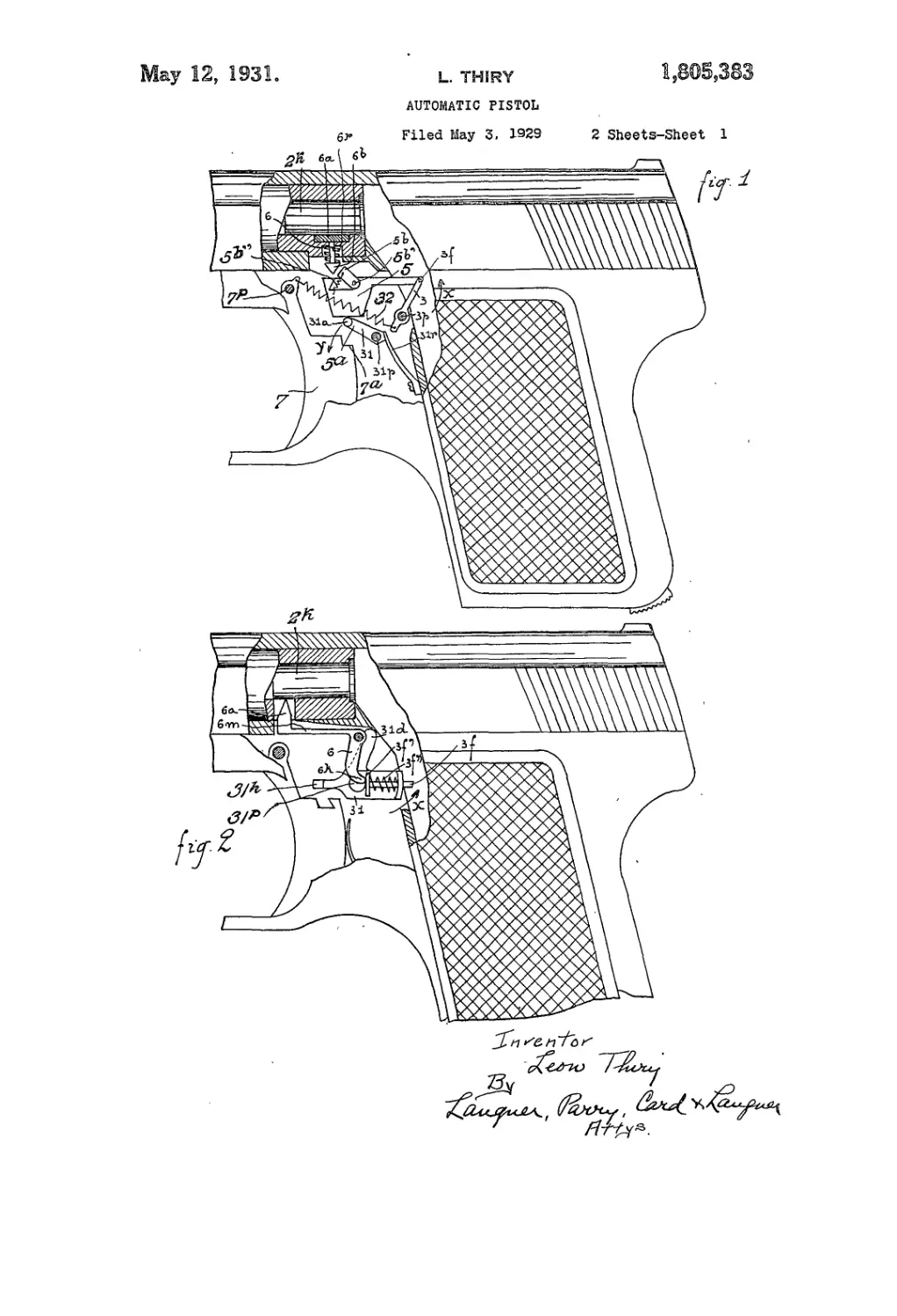
Figure 1 is a diagrammatic view of an
arrangement by means of which the firearm
is put into a condition of safety by the inser-
tion of the magazine if a cartridge is in the
barrel.
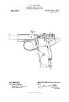
Figure 2 shows another arrangement pro-
viding the same effect.
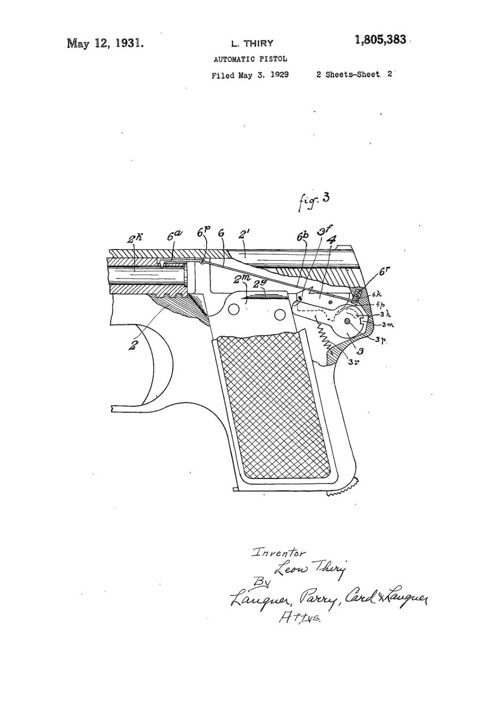
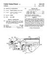
Figure 8 shows an arrangement in which
it is impossible to replace the magazine as
long as a cartridge is in the barrel.
In the case shown in Figure 1, the various
25
30
35
40
45
parts occupy the position shown in the draw-
ing when the magazine is withdrawn.
When the magazine is again inserted the
lever 3 pivoted at &p upon the frame of the
firearm and the end 3/ of which projects into
the lodgment of the magazine, will be dis-
placed in the direction of the arrow X. This
displacement will produce the displacement
of the member 5. This member rests upon
the part 31a of the chamber 31 capable of
putting the firearm in a condition of safety
by the fact that it places itself in the notch
7a of the trigger 7 pivoted at 7p. The safety
member 31 is held in one or the other of its
positions by a spring 31r acting upori two
flats provided upon the said member 31
which is pivoted at 31p. The member 5 is
provided with a projection 5b which cooper-
ates with the head 6b of a member 6 one part
6a of which is adapted to penetrate into the
chamber of the barrel when there is no car-
tridge in the latter. This member 6 is con-
stantly urged by the spring 6r in a direction
such that the member 6a does not occupy the
chamber of the barrel. The relative tensions
of the springs 6r and 31r are such that, as a
result of the movement produced by the dis-
placement of the member 5, the spring 6r will
be adapted to yield before the spring 31r per-
mits the displacement of the safety member
31. Consequently? if there is no cartridge in
the barrel, the projection 5b of the member 5
will move the head 6b of the member 6 by the
cooperation of the inclines with which the
contacting parts are provided and the pro-
jection 5b will place itself behind the head 6b.
During this movement, the member 5 will
have simply slide along the part 31a of the
safety member 31 without moving the latter.
On the contrary, if a cartridge is situated in
the chamber of the barrel 2k the member 6 will
not be able to yield to the action it undergoes'
as a result of jbhe cooperation of the inclines
on the projection 5b and on its head 6b so that
the member 5, in order to answer to the pres-
sure it undergoes on the part of the lever 3
moves in the direction of the arrow X when
the magazine is inserted, will have to slide
along the incline on the head 6b of the mem- 100
ber 6 while moving the lever 31 in the direc-
55
50
№
70
75
80
85
00
95
50
2
1,806,383
tion of the arrow Y which lever will thus put
the firearm in a condition of safety.
The safety device can be made inoperative
for example by a direct action exerted by 'the
5 operator upon a part of the member 31 pro-
jecting outside the firearm. According to a
modified construction this result may also be
obtained by means of one of the parts which
move when the firearm is cocked. The lever
10 3 is constantly urged to engage in the lodg-
ment for the magazine by means of a spring
3r the tension of which is sufficient to move the
member 6 against the action of its return
spring 6r.
15 As shown in Fig. 1, the projection 55 may
if desired be formed by a finger pivoted at
5l>' upon the member 5 and adapted to be dis-
engaged under the action of a spring 55".
By means of this arrangement, when the
20 lever 3 moves in an opposite direction to that
of the arrow X, as occurs when the magazine
is removed, the member 5 will be able to move
without producing the displacement of the
safety member 31 if the tension of the spring
25 55" is such that this spring becomes com-
pressed before the spring 31r permits the
displacement of the safety member 31.
In the case shown in Figure 2, the safety
member 31 pivoted at 31p is adapted to act by
30 means of its face 31Л. upon the trigger so
as to put the firearm in a condition of safety.
In this member moves a slide block 3/ which
projects into the magazine lodgment against
the opposing action of its return spring 3/"
35 when the end 67г of the lever 6, the end 6<z of
which is adapted to engage in the chamber
of the barrel, acts upon the part 3f' of this
member 3/. This action is produced as soon
as a cartridge is engaged in the chamber of
40 the barrel 2&.
Nevertheless, if at this moment the maga-
zine is in its lodgment, the member 3/ abuts
against this magazine and it cannot yield to
the pressure exerted by the member 6. In
45 order to permit the part 6a of this member
to be withdrawn however, one of the arms
such for example as the arm 6n which this
member 6 comprises, is formed of an elastic
, material. The tension given to this arm is
50 such that if the magazine is not in its lodg-
ment the spring 3/" will be compressed be-
fore this arm yields.
When the magazine is placed in position if
a cartridge is in the barrel, the end 3/ which
55 projects into the magazine lodgment is car-
ried along in the direction of the arrow X
thus placing the member 31 in the safety po-
sition. The safety device is disengaged by
means of one of the members which move
oo when the pistol shown in Figure 2 is cocked.
For this purpose the movable breech is pro-
vided with a projection not shown in the
drawings, adapted to abut against the arm
31г? carried by the member 31 in such a way
65 as to move this arm in this member in the op-
posite direction to that of the arrow X. The
projection provided upon the movable breech
will however be situated at such a distance
that before it comes into contact with the
above mentioned arm 31, the cartridge which
was situated in the chamber of the barrel will
have been extracted by the normal movement
of the usual extractor so that the member 3/
will have been able to withdraw, completely
in the interior of the member 31 so as to per-
mit the rotation of the latter in the opposite
direction to that of the arrow X in spite of
the presence of the magazine in its lodgment.
In the case shown in Fig. 3, the sear 4 is put
in a condition of safety by a stop 3h which
becomes placed beneath an incline 4y on
the sear. This stop 3h is made rigid with a
member 3 pivoting at 3p upon the frame and
moved when the magazine 2//?, is withdrawn
into its operative locking position by a
spring 3r.
This member 3 is controlled in its locking
position as a function of the presence of a
cartridge in the barrel Ik of the firearm. This
control is obtained by means of a lever 6 piv-’
oted at 6p upon the frame and one of the
arms 6a of which penetrates into the barrel
while the other arm 6Ъ penetrates into a suit-
able notch formed in a slide block 6k urged
out of its lodgment by a spring 6r bearing
upon the end of the above mentioned lodg-
ment formed in the frame. The locking of
the safety device by the said lever is obtained
by forming in the member 3 a notch 3m in
which engages the above mentioned slide
block 6k. When the member 3 is moved into
the position for which it puts the sear 4 in a
condition of safety, this member 3 will be
locked as long as there is a cartridge in the
barrel 27г.
In order to withdraw this cartridge it will
be sufficient to act in the usual manner upon
the slide 2y of the firearm. When this opera-
tion has been effected the arm 6a will pene-
trate into the chamber of the barrel and the
arm 6f will push the slide block 6 к to the end
of its lodgment and this slide block will thus
release the member 3 which may be brought
into its initial inoperative position by one of
the means described above.
It is to be noted that the magazine Im can-
not be put back in place as long as a cartridge
remains in the barrel. In fact, in order to
take up its place again the magazine must
push before it the end 3/ of the member 3
which is locked by the slide block 6k as long
as a cartridge is in the barrel.
The invention also provides for the com-
bination of a safety catch controlling device
as specified above to be combined with a con-
trol device constructed in such a way as to
cause the firearm to be put in a condition of
safety when the magazine is removed and for
this to be done in such a way that the sub-
sequent insertion of the magazine leaves the
1,80В, 383
5
10
15
20
25
30
35
40
45
50
55
50
•’5
firearm in a condition of safety if it is al-
ready in such a condition.
By locking the finger forming the projec-
tion 55 in the form of construction shown
in Figure 1, in such a way as to prevent it
swinging about the pivot 55', a firearm will
be obtained which will be put in a condition
of safety when the magazine is removed if
a cartridge is at this moment in the barrel.
It goes without saying that when the maga-
zine is again inserted it will not affect this
condition of safety.
What I claim is:
1. Automatic weapon comprising an ele-
ment having a portion capable of project-
ing into the seat of the magazine so as to be
displaced by the magazine upon its intro-
duction into the said seat, a safety device for
the weapon controlled by this element, an
element one part of which is withdrawn be-
yond the chamber of the gun when the lat-
ter contains a cartridge, and means provid-
ing a connection between this element and
the said element, so that the replacing of the
weapon in condition for firing by the rein-
troduction of the magazine into its seat
would be impossible as long as a cartridge
still remains in the chamber of the gun.
2. Automatic weapon comprising an ele-
ment having a portion capable of projecting
into the seat of the magazine so as to be dis-
placed by the magazine upon its introduc-
tion into the said seat, a safety arrangement
for the weapon controlled by this element,
an element, whereof a portion is extended be-
yond the chamber of the gun when the latter
contains a cartridge, and a member which
positively places the safety arrangement in
its safety position when this member engages
upon said element, which by reason of this
engagement is urged to penetrate by one of
these portions into the chamber of the gun,
this penetration not having taken place and
the placing in safety position being effec-
tively produced if the magazine is returned
into position, and then that a cartridge is
again placed into the chamber of the gun.
3. Automatic weapon comprising an ele-
ment having a portion capable of projecting
into the seat of the magazine so as to be dis-
placed by the magazine upon its introduc-
tion into the said seat, a safety device for
the weapon controlled by this element, an
element, a portion of which is extended be-
yond the chamber of the gun when the latter
does not contain a cartridge and a member
which positively places the safety arrange-
ment into the safety position when it is dis-
placed by the returning of the magazine to
position, the above named portion capable of
projecting into the seat of the magazine be-
ing и^ёсГ by a return spring to not project
into the seat of the magazine, this projec-
tion not taking place except when this por-
tion is pushed by another portion of th®
said element, a portion of which is fed be-
yond the chamber of the gun when the latter
contains a cartridge.
4. Automatic weapon according to claim 3
in which the safety lever has an element ca- 70
pable of being influenced at the moment of
cocking by an element of the cocking mecha-
nism, so as to provide the freeing of the de-
tent previously obstructed.
5. Automatic weapon comprising a safety 75
arrangement placed in its safety position by
the withdrawal of the magazine by means of
the penetration of an element into the seat of
the magazine and means for obstructing this
element in its safety position by a portion so
actuated by an element, a portion or which
is extended beyond the chamber of the gun
when the latter contains a cartridge, so that
returning the magazine to place is prevented
while a cartridge remains in the chamber of 85
the gun.
In testimony whereof, I have affixed my
signature.
LEON THIKY.
100
105
11c
115
12C
121