/


Tags: weapons military affairs patent
Year: 1990


Text
4,932,309
Jun. 12, 1990
United States Patent [«]
Barrett
[ii] Patent Number:
[45] Date of Patent:
[54] TRIGGER MECHANISM FOR SEMI-AUTOMATIC RIFLE
[76] Inventor: Ronnie G. Barrett, P.O. Box 1077,
[21] Appl. No.: Murfreesboro, Tenn. 37130 339,299
[22] Filed: Apr. 17,1989
[51] Int. Cl? .... F41C 19/14
[52] u.s. a 89/145; 42/69.02
[58] Field of Search 42/69.02; 89/141, 145
[56] References Cited U.S. PATENT DOCUMENTS
4,677,897 7/1987 Barrett ........................ 89/166
4,867,040 9/1989 Barrett ........... 89/172
Primary Examiner—Stephen C. Bentley
Attorney, Agent, or Firm—Harrington A. Lackey
[57] ABSTRACT
A trigger mechanism for a semi-automatic rifle in which
a latch-disconnector hook member is mounted on the
trigger member for engaging a catch on the transfer bar
to temporarily hold the transfer bar down while the
trigger is pulled and after the transfer bar has been
depressed and thrust rearward by the rearward move-
ment of the cocking lever to ensure the cocking of the
firing pin as the bolt carrier moves over the transfer bar.
4 Claims, 1 Drawing Sheet
U.S. Patent
Jun. 12,1990
4,932,309
4,932,309
2
TRIGGER MECHANISM FOR SEMI-AUTOMATIC
RIFLE
BACKGROUND OF THE INVENTION 5
This invention relates to a trigger mechanism for a
semi-automatic rifle, and more particularly to a positive
latching-disconnecting mechanism for the transfer bar
during he retraction of the bolt carrier.
In the trigger mechanism in a semi-automatic rifle,
such as that disclosed in FIGS. 9 and 10 of my prior
U.S. Pat. No. 4,677,897, and in my со-pending applica-
tion Ser. No. 115,821, now U.S. Pat. No. 4,867,040 filed
Nov. 2, 1987, for “SELF-UNLOCKING DEVICE ..
FOR RECOILING BOLT CARRIER AND BAR-
REL IN A SEMI-AUTOMATIC RIFLE”, the trigger
cooperates with a pivotal transfer bar and a vertically
reciprocable sear for catching and holding (cocking)
the firing pin in a retracted position when the trigger is
relaxed and for releasing the firing pin to fire the car-
tridge, when the trigger is pulled.
After the cartridge is fired and while the bolt carrier
is retracting, the cocking lever is pivoted to urge the
rear hook on the firing pin beneath the sear hook. As the 25
cocking lever moves rearwardly over the transfer bar,
the transfer bar is normally depressed. The sear hook
drops and engages the rear hook of the firing pin, in
order to cock the firing pin. However, on occasions,
and particularly as the cooperating parts of the trigger
mechanism become worn, the transfer bar may slip and
remain in or return to an upper position. When the bolt
carrier returns to its-battery position, the sear will be
forced upward by the elevated transfer bar to release
the firing pin. Since the firing pin is not held in its re- 35
tracted position, it will continue to repetitively move
forward and fire, retract, move forward and fire, as long
as the trigger is held in its rearward position. Thus, the
semi-automatic rifle becomes a fully automatic rifle
when such action is not desired. 40
SUMMARY OF THE INVENTION
It is therefore an object of this invention to provide in
a semi-automatic rifle having a trigger mechanism simi-
lar to that described above, a latch-disconnector mecha-
nism for positively holding the transfer bar down while
the trigger is in its pulled position and as the bolt carrier,
sear and cocking lever move rearwardly over the top of
the transfer bar. With the transfer bar held down, the
sear hook will always engage and cock the firing pin in
its retracted position, and thereby maintain the semi-
automatic function of the rifle.
More specifically, a latch-disconnector hook is at-
tached to the upper portion of the trigger member so
that when the trigger is pulled, the hook will’ move
forward. Then, as the transfer bar is pushed downward
and thrust rearward by the rearward movement of the
cocking lever as the bolt carrier retracts, a catch ledge
formed on the transfer bar is moved below and beneath
the latch-disconnector hook for cooperative engage-
ment between the two in order to hold the transfer bar
down as long as the trigger is pulled rearward. This
action permits the sear to drop causing the sear hook to
engage the rear hook on the firing pin to hold the firing
pin in its retracted position until the bolt carrier has
again been moved forward to its battery position and
the trigger actuated to release the firing pin and fire the
cartridge.
45
50
55
60
65
BRIEF DESCRIPTION OF THE DRAWINGS
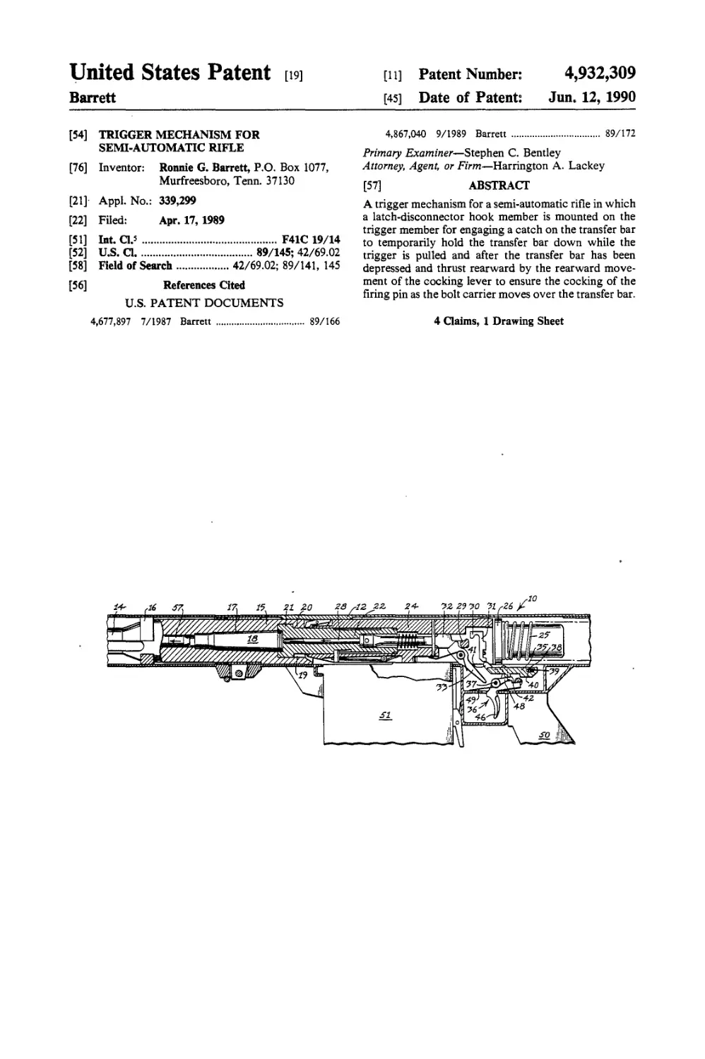
FIG. 1 is a fragmentary elevational view of the mid-
dle portion of a semi-automatic rifle, made in accor-
dance with this invention, with portions disclosed in
section, and disclosing the rifle in a firing position, with
the trigger pulled rearward;
FIG. 2 is a fragmentary elevational view of the trig-
ger mechanism portion of the rifle disclosed in FIG. 1,
in which the bolt carrier is retracting, the trigger is still
in a rearward position, but the firing pin is cocked and
the transfer bar latched in a down position, and further
illustrating the cocked firing pin in phantom in a further
rearward position;
FIG. 3 is a fragmentary elevational view similar to
FIG. 2 in which the trigger is released, and the bolt
carrier, together with the cocked firing pin is in its
forward battery motion;
FIG. 4 is an enlarged fragmentary plan sectional view
of a portion of the trigger mechanism, taken along the
line 4 -4 of FIG. 3; and
FIG. 5 is an elevational view taken from the opposite
side of FIG. 3, and disclosing only the trigger member,
the transfer bar, and the sear.
DESCRIPTION OF THE PREFERRED
EMBODIMENT
Referring now to the drawings in more detail, FIG. 1
discloses a semi-automatic rifle 10 made in accordance
with this invention, including an elongated housing 12.
An elongated barrel 14 is slidably received within the
housing 12 for longitudinal reciprocable movement.
The enlarged cylindrical rear end portion or extension
of the barrel 15 (FIG. 1) is slidably received within a
rear bushing or annular stop member 16.
The barrel 14 is normally biased forward by barrel
springs, not shown, in a manner similar to that disclosed
in my prior pending application Ser. No. 115,821, now
U.S. Pat. No. 4,867,040.
The enlarged rear end portion or rear barrel exten-
sion 15 contains a barrel chamber 17 for receiving a
cartridge 18.
The barrel extension 15 includes a rear locking cham-
ber 19 and a plurality of circumferentially spaced radi-
ally inward directed barrel locking lugs 20. The barrel
locking lugs 20 are adapted to cooperate with a plural-
ity of circumferentially spaced radially outward pro-
jecting bolt locking lugs 21 formed on the front end
portion of the bolt 22 which is reciprocably carried
within a bolt carrier 24. The bolt carrier 24 is adapted to
move reciprocably and longitudinally within the hous-
ing 12 and between the barrel extension 15 and the front
end of the recoil spring 25 provided with a front buffer
pad or member 26 for engaging the rear end of the bolt
carrier 24.
An elongated firing pin assembly 28 is reciprocably
mounted longitudinally and coaxially within the center
of the bolt 22, in a conventional manner. The rear end
portion of the firing pin assembly 28 includes a firing pin
hook 29 adapted to cooperate with the sear hook 30 of
a vertically reciprocable sear 31 in a conventional man-
ner.
A vertical slot 32 in the rear portion of the firing pin
assembly 28 is adapted to receive a pivotal cocking
lever 33.
A coil spring, not shown, within the firing pin assem-
bly 28 within the bolt carrier 24 normally urges the
firing pin forward.
4,932,
3
The sear 31 is adapted to be raised to disengage the
rear hook 29 of the firing pin 28 from the sear hook 30
when the elongated transfer bar 35 is raised or lifted by
the trigger member 36 when pivoting in a counter-
clockwise direction about the transverse trigger pivot 5
pin 37.
The transfer bar 35 is provided in its rear end portion
with an elongated transverse slot 38 receiving a transfer
pivot pin 39. The length of the transverse slot 38 may be
2 to 3 times as great as the diameter of the pivot pin 39. 10
Moreover, the transfer bar 35 is normally urged for-
ward relative to the pivot pin 39 by one or more spring
members 40, (FIGS. 1 and 3).
The front end portion of the transfer bar 35 is pro-
vided with a pair of slightly upward projecting trans- 15
versely spaced ears or lifter cams 41 for engaging the
bottom of the sear 31, to enable the sear 31 to be lifted
when the transfer bar 35 is pivoted upward about the
pivot pin 39.
Formed on the bottom surface of the transfer bar 35 20
is a downward projecting lug or land 42.
The trigger member 36 includes a mounting body 44
through which is journaled the trigger pin 37 and which
extends through the opposed walls of the trigger hous-
ing 45. The trigger housing 45 forms a part of the rifle 25
housing 12, but depends below the bolt carrier 24.
Fixed to and depending from the mounting body 44 is
the trigger 46. Projecting rearwardly from the mount-
ing body 44 is the trigger lever 47. Projecting upward
from and fixed to either the mounting body 44 or the 30
trigger lever 47 is a lifting lug or trigger cam 48, which
registers with the depending transfer bar lug or land 42
when the transfer bar 35 is in its forward position, such
as illustrated in FIGS. 1 and 3. The trigger 46 is nor-
mally biased forward to its inoperative position by the 35
coiled trigger spring 49.
The features thus far described are old in the art, as
described in Applicant’s со-pending application Ser.
No. 115,821, now U.S. Pat. No. 4,867,040 filed Nov. 2,
1987. 40
A pistol grip stock 50 is fixed upon the rifle housing
immediately behind the trigger 46, in a conventional
manner. Mounted in front of the trigger 46 is a conven-
tional magazine 51 for feeding cartridges to the bolt 22.
In order to prevent the transfer bar 35 from remain- 45
ing in its upper pivotal position while the trigger 46 is
pulled rearwardly and the bolt carrier 24 is retracting, a
latching-disconnector mechanism is provided for nor-
mally holding the trigger member 36 and the transfer
bar 35 together in the lower position of the transfer bar 50
35 when the trigger 46 is in its rearward position.
This latch-disconnector mechanism is preferably pro-
vided in the form of an upstanding hook or hook mem-
ber 52 pivotally mounted upon arid projecting upward
from the mounting body 44. The hook member 52 is 55
preferably provided with a forward projecting bill 53
which is adapted to fit over a rearward projecting catch
member or ledge 54 having an upward directed face or
top surface 55. This catch member 54 is formed in the
front end portion of the transfer bar 35. The hook mem-
ber 52 is preferably mounted for pivotal movement
upon the trigger pivot pin 37, and is biased to its for-
ward position by a spring, not shown.
As best disclosed in FIGS. 3, 4, and 5, when the
trigger 46 is not actuated and in its inoperative forward
position, the latch hook or hook member 52 will lie
behind the catch member 54, and therefore there will be
no engagement of the hook member 52 with the catch
309
4
member 54 regardless of the pivotal position of the
transfer bar 35.
When it is desired to fire the rifle 10, the trigger 46 is
squeezed and pulled rearwardly causing the trigger
member 36 to rotate in a counter-clockwise direction
about the trigger pivot pin 37, as illustrated in FIGS. 1
and 2. After the trigger 46 is pulled, the trigger cam 48
is elevated to engage the depending lug 42 and lift the
transfer bar 35. When the bolt carrier 24 is forward in its
battery position, the rising transfer bar 35 will cause the
cam lugs 41 to engage the bottom of the sear 31 thereby
lifting the sear 31 and causing the sear hook 30 to rise
above and disengage the rear hook 29 of the firing pin
28. The firing pin 28 will immediately be released to
rapidly move forward under the action of the firing pin
spring to cause the firing pin 28 to detonate the car-
tridge 18 in order to fire a bullet or projectile 57
through the barrel 14, as illustrated in FIG. 1.
During the firing operation, although the latch-dis-
connector hook 52 will move forward, nevertheless,
because the transfer bar 35 is rising, the latch-disconnec-
tor hook 52 will move beneath the catch member 54 so
that there will be no engagement of the latch-disconnec-
tor hook 52 with the catch member 54 during the firing
operation.
However, after the firing operation, the explosion
within the cartridge 18 causes the bolt carrier 24 to
rapidly recoil and retract against the action of the recoil
spring 25. As best illustrated in FIG. 2, as the bolt car-
rier 24 is retracting the cocking lever 33 is rotated in a
clockwise direction causing the rear hook 29 of the
firing pin 28 to move rearward beneath the sear hook
30. Moreover, the cocking lever 33, since it depends
below the bolt carrier 24, engages the transfer bar 35
normally depressing the transfer bar 35 in a lower posi-
tion, and also forcing the transfer bar 35 rearward
against the action of the transfer bar spring 40 causing a
slight rearward movement of the transfer bar 35 relative
to the transfer pivot pin 39, as illustrated in FIG. 2.
When this compound motion occurs, the catch member
54 forces the latch-disconnector hook 52 pivotally rear-
ward against the action of its own spring, not shown,
causing the top surface 55 to slip beneath the bill 53 of
the latch-disconnector hook 52, causing the transfer bar
35 to be latched in its lower position against the trigger
mechanism 36, as illustrated in FIG. 2.
This latching action assures that the sear 31 is free
from contact with the transfer bar 35 when the bolt
carrier 24 returns to battery, so that there will be no
additional firing action until the trigger 46 is pulled
again.
It should be noted in FIG. 2, that the latching action
between the latch-disconnector hook 52 and the catch
member 54 can only occur while the trigger 46 is pulled
rearward. When the trigger 46 is released to its forward
position, as illustrated in FIG. 3, the latch-disconnector
hook 52 is moved rearward and downward away from
engagement with the ledge or catch member 54 to re-
lease the transfer bar 35, which is now in its lower posi-
tion and in readiness for the next firing operation.
The movement of the bolt carrier 24 is so fast that the
operator may still have his finger on the trigger 46 as
the bolt carrier 24 and the sear 31 move rearwardly past
the trigger mechanism. Thus, if the cocking lever 33 is
not performing its function or there are parts which are
not catching or the transfer bar 35 remains in its upper
position, while the trigger 46 is in its rearward position,
the firing pin rear hook 29 will not be caught because
309
6
(c) an elongated tran'sfer bar having a rear end por-
tion and a front end portion,
(d) a transfer pivot pin mounting said rear end portion
of said transfer bar in said housing in the longitudi-
nal path of said cocking lever for pivotal move-
ment about a transverse axis above said trigger
member and limited longitudinal movement rela-
tive to said transfer pivot pin,
(e) transfer spring means biasing said transfer bar
forward relative to said transfer pin,
(f) sear lifter means on the front end portion of said
transfer bar for engaging and lifting said sear,
(g) cooperative means on said trigger member and
said transfer bar for lifting said transfer bar when
said trigger is pulled rearward,
(h) a catch member on said front portion of said trans-
fer bar, and
(i) a latch-disconnector hook member projecting up-
ward from said mounting body and having a pro-
jecting hook adapted to engage said catch member
to hold said transfer bar down in a caught position
only when said trigger has been pulled rearward
and said transfer bar has been thrust downward and
rearward by said cocking lever.
2. The invention according to claim 1 in which said
catch member comprises a ledge having a top surface
projecting rearward, said hook having a forward pro-
jecting bill adapted to fit over and engage said top sur-
face of said ledge in said caught position.
3. The invention according to claim 2 in which said
cooperative means comprises a lift cam projecting up-
ward from said trigger member and a lug projecting
downward from said transfer bar engaging said lift cam.
4. The invention according to claim 2 in which said
hook is adapted to move forward, beneath and disen-
gaged from said ledge when said transfer bar is in its
forward position and lifted upward by said trigger
member.
*****
4,932,
5
the sear 31 is still in its elevated position and the firing
operation will automatically be repeated without any
further trigger actuation. Thus, an inadvertent auto-
matic firing will result instead of the desired semi-
automatic function. 5
However, the latching mechanism including the
latch-disconnector hook 52 and the catch member 54
obviate this inadvertent hanging or suspension of the
transfer bar 35 in its elevated position as the cocking
lever 33 and the bolt carrier 24 move over the transfer 10
bar 35.
The rear trigger lever 47 is shown in the drawings as
cooperating with a rotary elongated safety member or
spindle 60, which includes a notch 61. As illustrated in
the drawings, the notch 61 is in its firing position so that 15
the trigger member 46 is free to pivot and perform its
normal firing function. The safety spindle 60 and the
cooperating trigger lever 47 are well known in the art,
as illustrated in FIGS. 9 and 10 of my prior U.S. Pat.
No. 4,677,897.
What is claimed is:
1. In a semi-automatic rifle having an elongated hous-
ing including a reciprocable bolt carrier, a bolt within
the bolt carrier, a firing pin within the bolt having a rear 25
hook, a vertically reciprocable sear within the bolt
carrier and having a sear hook adapted to engage the
rear hook when the firing pin is in a rear cocking posi-
tion, and a cocking lever pivotally mounted within and
depending from the bolt carrier and cooperative with 30
the rear hook for cocking the firing pin, a trigger mech-
anism comprising:
(a) a trigger member comprising a mounting body
and a trigger depending from said mounting body,
(b) a trigger pivot pin supporting said mounting body 35
on said housing below said bolt carrier for pivotal
movement of said trigger member about an axis
transverse to said elongated housing, and a trigger
spring biasing said trigger forward,
45
50
55
60
65