/

Tags: weapons military affairs patent
Year: 1996


Text
1111111Ш
US005513461A
United States Patent [19] [ii] Patent Number: 5,513,461
Weldle [45] Date of Patent: May 7, 1996
[54] LIGHT-WEIGHT AUTOMATIC RIFLE
[75] Inventor: Helmut Weldle, Obemdorf-Beffendorf,
Germany
[73] Assignee: Heckler & Koch, Oberndorf, Germany
[21] Appl. No.: 215,854
[22] Filed: Mar. 21,1994
[30] Foreign Application Priority Data
Mar. 24, 1993 [DE] Germany ........... 93 04 489.5
[51] Int. Cl.6 ....... F41A 21/48; F41C 23/18;
F41G 1/06
[52] U.S. Cl.......... 42/71.01; 42/75.02; 42/100
[58] Field of Search ........ 42/75.02, 75.03,
42/71.01, 72, 100
[56] References Cited
U.S. PATENT DOCUMENTS
2,970,398 2/1961 Crouch...................... 42/72
3,023,527 3/1962 Leek et al............... 42/75.03
3,488,488 1/1970 Crouch .................. 42/71.01
3,512,290 5/1970 Violette, Jr.; et al..... 42/75.01
3,877,167 4/1975 Keppeler ................ 42/75.02
3,939,589 2/1976 Tellie .................... 42/100
4,536,982 8/1985 Bredbury et al........... 42/71.01
4,779,370 10/1988 Cormack ................. 42/75.02
5,173,564 12/1992 Hammond.................. 42/75.03
5,357,703 10/1994 Chestnut et al.............. 42/50
FOREIGN PATENT DOCUMENTS
0055307A1 7/1982 European Pat. Off. .
63100 10/1982 European Pat. Off.......... 42/72
2573524 5/1986 France .
3620697A1 12/1987 Germany .
2092277 8/1982 United Kingdom .
Primary Examiner—Stephen C. Bendey
Attorney, Agent, or Firm—Cohen, Pontani, Lieberman, Pav-
ane; Christa Hildebrand
ABSTRACT
The present invention relates to a light-weight automatic
rifle with a housing with removable attachments, specifically
a longitudinally coaxial barrel, a grip with a trigger mecha-
nism, a shoulder rest, a clip, and sights. The slide slides back
and forth in the housing in back of the barrel and along a
cheek, resting in its frontmost position against the rear end
of the barrel and with locking components that securely
engage accommodations in the housing. The housing is a
hollow plastic housing and it accommodates a metal sleeve,
which is coaxial with the barrel. The rear of the barrel is
inserted in the front of the sleeve, and the accommodations
are on the rear of the sleeve.
10 Claims, 2 Drawing Sheets
U.S. Patent
May 7, 1996
Sheet 1 of 2
5,513,461
FIG. I
U.S. Patent
May 7,1996
Sheet 2 of 2
5,513,461
5,513,461
1
LIGHT-WEIGHT AUTOMATIC RIFLE
BACKGROUND OF THE INVENTION
1. Field of the Invention
The present invention relates to a light-weight automatic
rifle with a housing with removable attachments, specifically
a longitudinally coaxial barrel, a grip with a trigger mecha-
nism, a shoulder rest, a clip, and sights. The slide slides back
and forth in the housing in back of the barrel and along a
cheek, resting in its frontmost position against the rear end
of the barrel and with locking components that securely
engage accommodations in the housing. The housing is a
hollow plastic housing and it accommodates a metal sleeve,
which is coaxial with the barrel. The rear of the barrel is
inserted in the front of the sleeve, and the accommodations
are on the rear of the sleeve.
All terms referring herein to spatial direction are to be
understood as applied to the weapon conventionally leveled.
2. Description of the Related Art
The housing of a rifle of this type comprises at least two
halves stamped out of sheet metal and welded together edge
to edge. All parts that accommodate such keying pins as the
pins that attach the butt or grip are often reinforced with
hollow rivets.
The rear of the barrel is generally engaged by projections
from the sheet-metal halves or secured by at least one keying
pin in the accordingly assembled housing.
The sights rest at least to some extent on the housing,
although some components can also be mounted on the
barrel itself.
In contrast to weapons of classic design, which have a
slide sliding back and forth in a track that is open at the top,
the housing of such a light-weight automatic rifle provides
the great advantage of being considerably less susceptible to
contamination and weather. The closed and box-like housing
can also easily be fabricated of sheet metal, mainly by
stamping, and machined only at various points for finishing.
The forged parts employed in the classic weapon on the
other hand must be extensively and expensively machined.
There are also drawbacks of course to two-part sheet-
metal housings. They may have difficult-to-access seams,
where the two halves are welded together for instance, that
moisture can accumulate in and cannot be kept clean by
conventional methods. Rust can deposit in the seams and
eventually weaken the material, threatening the safety of the
weapon as a whole.
It is impossible to employ stainless-steel sheet instead of
the metal employed up to now. Stainless steel is not ductile
enough for satisfactorily shaping into a light-weight auto-
matic-title housing.
Welding together the two halves of the housing also
results in warping, which necessitates the aforesaid follow-
up machining. Finally, the known method of manufacture is
expensive.
SUMMARY OF THE INVENTION
With the foregoing state of ±e art as a point of departure,
the object of the present invention is to eliminate the
aforesaid drawbacks and in particular to allow cost-effective
manufacture with less follow-up machining of a light-weight
automatic rifle susceptible to little or no corrosion.
5
10
15
20
25
30
35
40
45
50
55
60
65
2
The housing of the rifle in accordance with the present
invention is entirely or at least extensively a single hollow
plastic component with a metal sleeve embedded in it made,
for example, by injection molding. The front of the housing
accommodates the barrel and the rear the locked slide. The
components that lock the slide engage the sleeve.
Making the stock of such weapons of plastic instead of the
traditional wood is admittedly basically known. Still, no
more dimensional stability or strength is demanded of the
plastic than of the wood.
Making the housing-like grip and slide of a semi-auto-
matic pistol or the housing of an automatic pistol of plastic
is also known. No particular precision or strength is
expected of the material in these weapons, however, because
the ammunition has little muzzle energy.
The accuracy of military pistols and automatic pistols is
not especially determinative, and distortions of the type that
may occur over time can be accepted as long as they are not
detrimental to the weapon’s overall function.
A rifle on the other hand shoots a cartridge with a much
higher muzzle energy than that shot by a pistol, and in
bursts, furthermore, in the event of a light-weight automatic
rifle. A higher level of accuracy on the o±er hand is
demanded of the rifle because a single shooter with such a
weapon must be able to effectively hit a human target from
several hundred meters away.
A metal sleeve that accommodates both the barrel and
accommodations for the slide-locking components is
inserted in the hollow plastic housing of the light-weight
automatic rifle in accordance with the invention. When the
weapon is fired, accordingly, the sleeve initially directly
transmits the very powerful forces that occur initially from
the barrel to the slide without participation by the plastic the
housing is made of. Only after complete release of the slide
will any forces worth mentioning affect the hollow plastic
housing, and they will by that time be considerably weaker
than those that occur just after the weapon is fired.
The combined mass of the barrel, sleeve, and slide in
existence when the weapon is fired does of course generate
a recoil that is transmitted to the housing, but the mass of the
housing itself is slight and is easily accommodated by the
shooter’s shoulder. Plastic can well resist such stresses.
Furthermore, the plastic itself can have enough resilience to
distribute point stresses over a wider area. Vibration-resis-
tant (hysteretic) plastics can also be of advantage in certain
instances.
The sleeve is definitely oblong and surrounded by rough
annular grooves accommodating the plastic. Each groove
transmits force to the plastic housing from the metal sleeve,
and, since there are so many grooves, any point stresses that
occur will not permanently deform the plastic.
It is also basically possible for one wall of the grooves to
be serrated in order to reduce the space between them. The
number of grooves can also be increased to promote trans-
mission of forces and decrease the potential for damage.
It will be preferable for the metal sleeve to have a radial
projection in the form of a short pin hammered into a radial
bore. The pin helps to stabilize the barrel, which is inserted
into the front of the sleeve and secured to it by a screw-on
cap. It represents an extremely simple means of ensuring
that the barrel will assume a constant and precisely repro-
ducible position.
Radial notches can also be introduced into the outer
surface of the metal sleeve and preferably at the rear, leaving
radial elevations between them that embed themselves in the
5,513,461
3
plastic of the housing. Such structures will prevent the
sleeve from twisting. Eight such notches uniformly and
symmetrically distributed around the outer surface of the
sleeve has been demonstrated practical.
Inner surfaces of the plastic housing act like a track for the
slide to slide along as the weapon reloads. These surfaces
can be left smooth enough while the housing is being
produced to require no finishing.
It is also possible to employ a plastic for the housing that
is hard enough to eliminate significant wear on the housing’s
cheeks.
Using such a wear-resistant plastic for the housing, how-
ever, can be a drawback because such materials are britde.
The housing is accordingly preferably made of high-viscos-
ity plastic and at least, and preferably, one metal cheek is
embedded in the housing to prevent the wear expected from
the softer plastic. The metal cheek guides the moving slide
and protects the plastic from wear. The friction-producing
combination of plastic housing and steel slide can be
retained otherwise.
A cheek can basically be positioned at any point along the
reciprocating interface between the slide and the housing.
One cheek will, however, preferably be positioned only
where the friction is expected to be severe because for
example of components that extend or move across the path
of the slide and subject any surface of the housing to
excessive stress. Such components are part of the lock, bolts,
etc. It must also be taken into consideration that lateral
sleeve ejection can subject the slide to a force of reaction,
stressing the cheek, usually the left cheek, opposite the
ejection port more than the other.
It is for this reason preferable for only the left guide to be
a cheek. This cheek will preferably consist of hardened and
annealed steel and be surface-treated to decrease friction or
to improve the adhesion of the plastic to the cheek or both.
The cheek can preferably be nitrocarburated.
The metal cheek is preferably a straight rail perforated by
wide bores. The plastic penetrates the bores at least and
preferably to some extent when the housing deforms, secur-
ing the cheek over a considerable portion of its area. Forces
transmitted to the cheek from the slide, which can be
considerably powerful when contaminants enter, can
accordingly be accommodated by a number of stubby plastic
pins constituted by the plastic invading the bores. There is
accordingly no risk of the cheek loosening subsequent to
considerable use.
The bores are preferably stamped and punched out, with
the openings toward the outside, the side of the guide
surface, countersunk and those toward the inside, toward the
plastic, cuffed. The plastic that invades the bores accord-
ingly hardens into pins. The head of the pins fill up the
countersinking. The rail is accordingly reliably locked into
position with its inner edge tighdy gripping the plastic.
The forces, which occur mainly when the weapon is fired,
are transmitted direcdy to the slide from the barrel by the
sleeve, and are consumed in releasing the slide. The total
force on the housing is accordingly relatively weak. The
housing can therefor be relied on not to deform in any way
subsequent to long use.
It is for this reason possible and of advantage for the
overall sights to be secured to the hollow plastic housing as
in another embodiment of the present invention. It is pref-
erable for the sights as a whole or at least the system
regularly employed to be integrated into the housing and
accommodated in a channel or depression therein. This
approach ideally protects the sights from damage. Certain
5
10
15
20
25
30
35
40
45
50
55
60
65
4
other features will be present when the plastic is not hard
enough to be britde. Impacts like those that occur when the
weapon is dropped are not transmitted to the sights to the
extent they are in a conventional light-weight automatic rifle
with a steel housing. Such impacts will accordingly also
have less effect on adjusting the sights.
It is basically possible for the hollow plastic housing or
housing to be manufactured by one of many appropriate
procedures, molding for example, and for the metal com-
ponents to then be inserted in appropriate structures in the
plastic.
At least one and preferably all of the metal components,
however, are in one practical and preferred embodiment
laminated into the hollow plastic housing while it is being
molded, preferably by injection.
It is in this event possible to take measures at the mold to
ensure highly precise and exact positioning of the metal
components. The metal parts are not only snugly surrounded
by the plastic but can even be wetted by it. It will accord-
ingly be impossible for any gaps to occur around the metal
components to accommodate corrosion.
The metal components are almost all simple machined
shapes, turned on automatic lathes for example. They are
accordingly not difficult to manufacture out of stainless
steel, and the risk of corrosion is entirely ruled out. The
metal components can also be surface-treated, hard-chromed
for example or bonded for example, before being embedded.
The hollow plastic housing in another embodiment of the
invention has a handle integrated into its top and extending
along its axis. This handle is hollow and can accommodate
a telescopic sight of the type in itself known in conjunction
with light-weight automatic rifles.
Screws and similar structures for adjusting such sights can
be accommodated to advantage in the housing. It is prefer-
able for the walls of the housing to be generally thicker than
those of a sheet-metal housing so that, when headless screws
are employed to adjust the sights, they will not project out
and be unintentionally turned. The screws can then be
secured by sealing the residual bores with lacquer.
These components of the sights in another embodiment of
the invention are preferably threaded bushings, two of which
(the one for elevation and the one for sweep) are in the wall
of the handle.
Another embodiment of the invention also has, in addition
to the regular sights, a lens-less emergency back-up sight on
the top of the handle.
Other devices that have previously been manufactured
separately and riveted or welded to the sheet-metal housing
can in accordance with another embodiment of the invention
also be molded onto the hollow plastic housing while it is
being manufactured. A shackle that accommodates a carry-
ing sling, preferably a depression with a vertical rod extend-
ing across it, can be integrated into the rear of the hollow
plastic housing, preferably into one side, and more prefer-
ably into the left side in another preferred embodiment of the
invention.
Half a hinge can be integrated into one side of the rear of
the hollow plastic housing opposite the shackle in another
embodiment of the invention, preferably in the form of a
number of overlapping projections with an aligned bore
extending through it. The bore is molded into the housing
and accommodates a pin that extends through a matching
hinge half on the shoulder rest.
Opposite the resulting hinge and accordingly immediately
below the shackle on the inner surface of the hollow plastic
5,513,461
5
housing is a barrier recess, which can be engaged by a bar
articulated to the shoulder rest.
The shoulder rest is secured ready-to-use as long as the
bar is in the barrier recess, and can be folded laterally in
front of the fight side of the housing once ±e bar has been
released.
The shoulder rest is a frame with at least one opening
through it. Once it has been folded forward, the opening or
openings will be in front of the ejection port and the shells
can be ejected unimpeded. The weapon will accordingly be
ready to use even with the shoulder rest forward.
In spite of the high demands on the various embodiments
of the hollow plastic housing with respect to precision, it
will be ready for installation immediately once the housing
has been removed from the injector and optionally once the
sprue has been removed—broken or sliced off, that
is—without any machining. The surface treatment abso-
lutely necessary in a metal housing can also be eliminated.
The plastic can also be colored any desired color, black,
khaki, or olive-green, or white for winter for instance.
The outer surface of the hollow plastic housing in another
embodiment can be rendered matt or rough by appropriately
modifying the mold. The rifle’s housing will accordingly not
reflect like a conventional housing of burnished or deep-
drawn.
The hollow plastic housing in accordance with the present
invention is accordingly not only more corrosion-resistant
but also primarily quicker and easier to manufacture than a
comparable sheet-metal housing.
BRIEF DESCRIPTION OF THE DRAWING
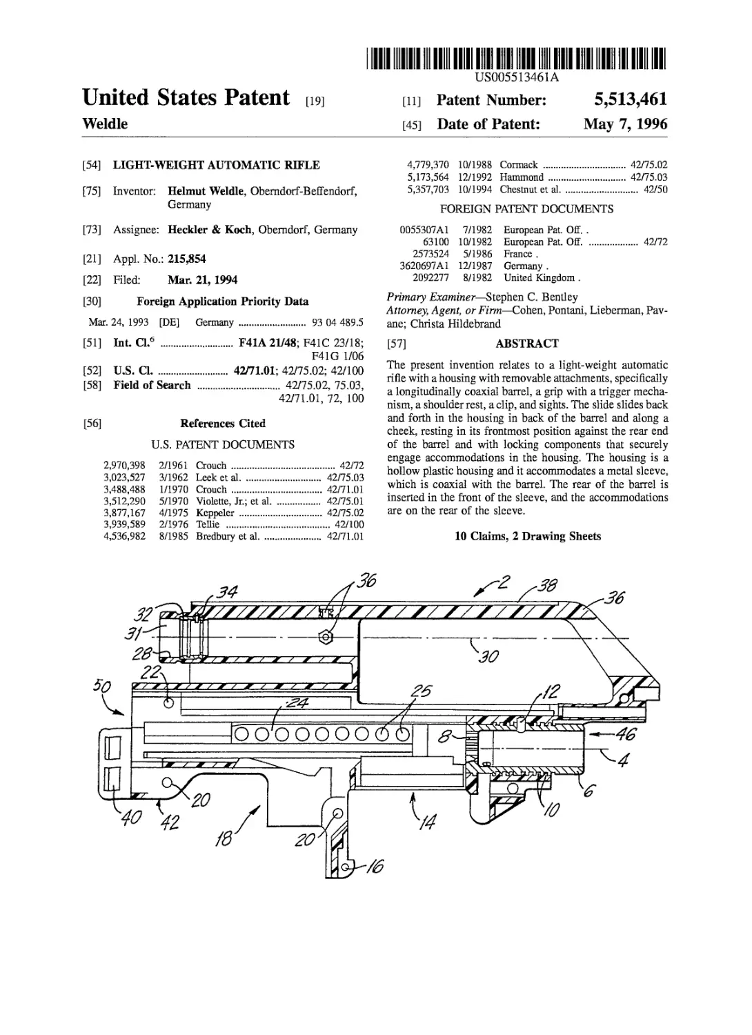
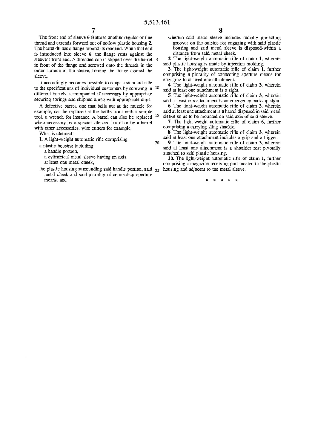
FIG. 1 shows an axial section of the housing of the light
weight automatic rifle.
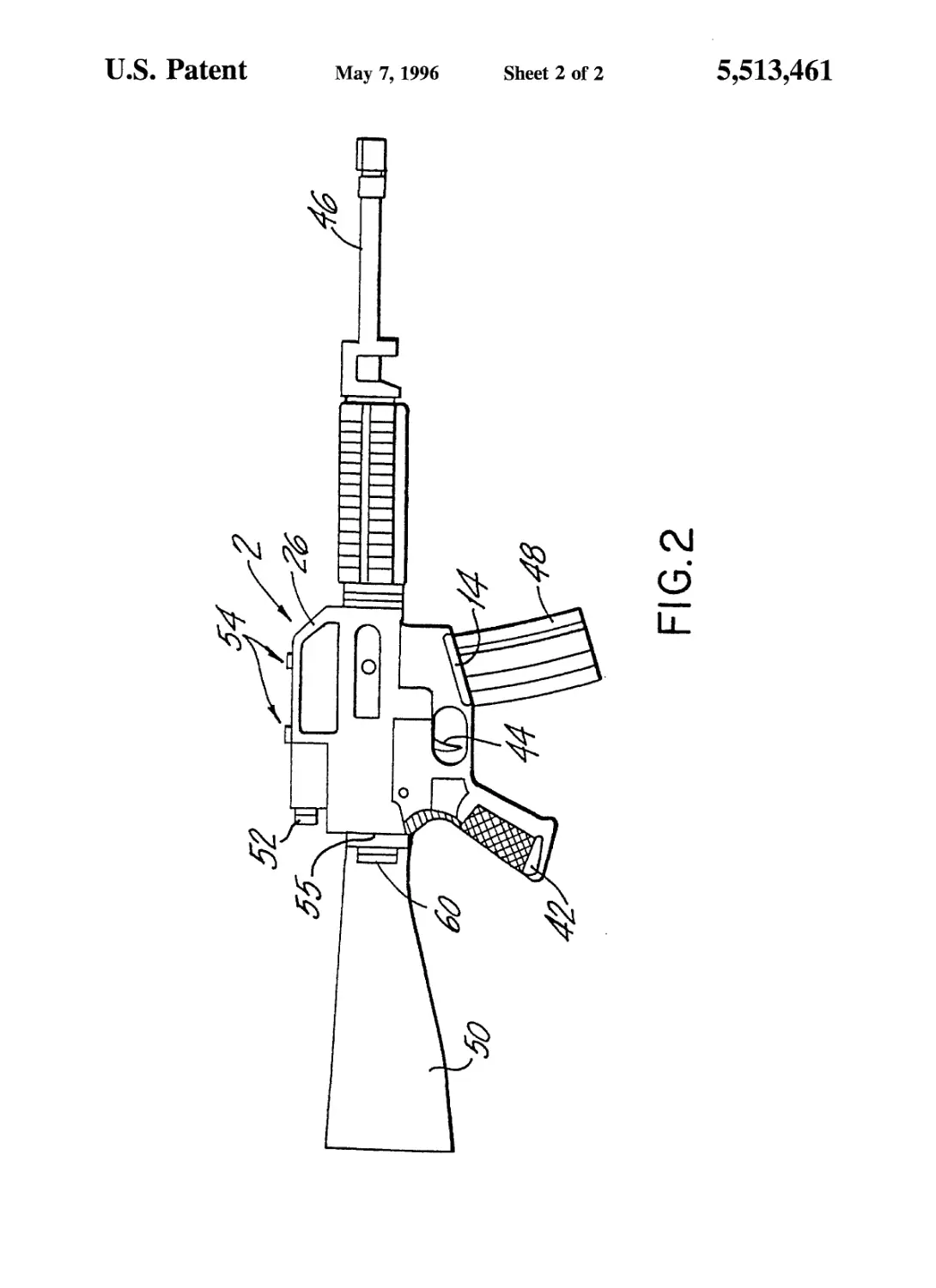
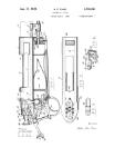
FIG. 2 shows a side elevation of the assembled plastic
rifle with attachments.
DESCRIPTION OF THE PREFERRED
EMBODIMENTS
One embodiment of the present invention will now be
described by way of example with reference to FIG. 1 and
FIG. 2.
The hollow plastic housing 2 accommodates coaxial with
its longitudinal axis 4 an essentially cylindrical steel sleeve
6. A cylindrical bore extends essentially all through, and
narrows at the rear end (at the left of the drawing) of, sleeve
6. Distributed around that end of the sleeve are radially
projecting bars 8. Keys on the head of an unillustrated slide
can be inserted forward (toward the right) between these
structures. The head is now rotated, and the keys will engage
behind bars 8. The slide is accordingly locked. The unillus-
trated barrel is secured inside sleeve 6, which attaches it to
the slide.
Distributed around the outside of sleeve 6 is a series of
grooves 10. Grooves 10 are interrupted by unillustrated
serrated notches and invaded by the plastic that housing 2 is
made of. The grooves transmit force longitudinally and the
notches transmit it around sleeve 6 and accordingly around
the barrel.
Inside hollow plastic housing 2 and below and behind
sleeve 6 is a magazine receiving port 14. Magazine receiving
port 14 accommodates a magazine clip 48 inserted from
below.
5
10
15
20
25
30
35
40
45
50
55
60
65
6
A bore 16 molded into hollow plastic housing 2 accom-
modates a clip holder.
Behind magazine receiving port 14 is another opening 18
that opens downward and allows the unillustrated slide to
operate in conjunction with components of the unillustrated
firing mechanism.
Molded into hollow plastic housing 2 on each side of
opening 18 is a bore 20 that accommodates grip 42 shown
in FIG. 2. Above each bore 20 is another bore 22. Bore 22
secures an shoulder rest 50 shown in FIG. 2 that accommo-
dates securing and shock-absorbing springs.
Hollow plastic housing 2 incorporates a passage extend-
ing back parallel with longitudinal axis 4 from the rear of the
housing and open at the rear. The slide slides back and forth
inside this passage. Molded into housing 2 along the left
inner surface of the passage and paralleling longitudinal axis
4 is a cheek 24. As will be evident from the drawing, cheek
24 is perforated by bores 25. These bores are invaded by the
still soft plastic when the housing is molded. The unillus-
trated slide slides along the exposed surface of the cheek.
Superimposed elongated webs project into the passage
from its right-side inner surface, the surface opposite cheek
24. The exposed inner edges of these webs extend describe
a vertical plane and constitute a surface opposite cheek 24
and helping to guide the slide. Between the two lowermost
webs is a cartridge-ejection port. Behind the rear edge of the
port is an outward projection. The projection prevents the
entire port from coming into contact with the ground or floor
when the rifle is laid down on its right side. The project also
constitutes a baffle that diverts ejected casings away from
the shooter. Below the metal sleeve is a magazine clip
receiving port 14 for receiving the magazine clip 48.
The passage that accommodates the slide is open at the
front, and the slide can at that point engage the top of a
plastic section that surrounds sleeve 6 from above. An
unillustrated loading lever for actuating the slide will pref-
erably be mounted on the same area of the slide. Further,
FIG. 2 illustrates how the above-described hollow plastic
housing rifle is assembled with attachments, the barrel 46
screwed into the steel sleeve 6 of FIG. 1, the shoulder rest
50 mounted to hinge 40 of FIG. 1, the sight 52, emergency
back-up sights 54 disposed on carrying handle 26, a trigger
mechanism 44, a grip 42, a carrying sling shackle 60. The
shoulder rest may also be pivotally hinged to the plastic
housing by a hinge 55.
A carrying handle 26 is integrated into the top of hollow
plastic housing 2. Handle 26 has a projection to the rear in
the form of a tube. The inner surface 28 centers on an axis
30 paralleling longitudinal axis 4.
The forward web, which extends as far a handle 26, of
hollow plastic housing 2, is breached around axis 30,
creating an open channel 31 that extends all the way through
the handle from front to rear.
A metal mount 32 is embedded in inner surface 28 just
forward of the rear end of the channel. Mount 32 accom-
modates the rear lens of a sight, secured by a pin 34.
Just behind the opening in the handle that surrounds the
tensioner, the inner surface 28 is penetrated by two threaded
bushings 36 molded securely into the plastic of housing 2.
Bushings 36 preferably accommodate an inside thread that
accept screws. The screws are employed to adjust the
vertical and horizontal position of the unillustrated sight
components.
An emergency back-up sight 54 of FIG. 2 is mounted on
the top of handle 26.
5,513,461
7
The front end of sleeve 6 features another regular or fine
thread and extends forward out of hollow plastic housing 2.
The barrel 46 has a flange around its rear end. When that end
is introduced into sleeve 6, the flange rests against the
sleeve’s front end. A threaded cap is slipped over the barrel
in front of the flange and screwed onto the threads in the
outer surface of the sleeve, forcing the flange against the
sleeve.
It accordingly becomes possible to adapt a standard rifle
to the specifications of individual customers by screwing in
different barrels, accompanied if necessary by appropriate
securing springs and shipped along with appropriate clips.
A defective barrel, one that bells out at the muzzle for
example, can be replaced at the batfle front with a simple
tool, a wrench for instance. A barrel can also be replaced
when necessary by a special silenced barrel or by a barrel
with other accessories, wire cutters for example.
What is claimed:
1. A light-weight automatic rifle comprising
a plastic housing including
a handle portion,
a cylindrical metal sleeve having an axis,
at least one metal cheek,
the plastic housing surrounding said handle portion, said
metal cheek and said plurality of connecting aperture
means, and
5
10
15
20
25
8
wherein said metal sleeve includes radially projecting
grooves on the outside for engaging with said plastic
housing and said metal sleeve is disposed-within a
distance from said metal cheek.
2. The light-weight automatic rifle of claim 1, wherein
said plastic housing is made by injection molding.
3. The light-weight automatic rifle of claim 1, further
comprising a plurality of connecting aperture means for
engaging to at least one attachment.
4. The light-weight automatic rifle of claim 3, wherein
said at least one attachment is a sight.
5. The light-weight automatic rifle of claim 3, wherein
said at least one attachment is an emergency back-up sight.
6. The light-weight automatic rifle of claim 3, wherein
said at least one attachment is a barrel disposed in said metal
sleeve so as to be mounted on said axis of said sleeve.
7. The light-weight automatic rifle of claim 6, further
comprising a carrying sling shackle.
8. The light-weight automatic rifle of claim 3, wherein
said at least one attachment includes a grip and a trigger.
9. The light-weight automatic rifle of claim 3, wherein
said at least one attachment is a shoulder rest pivotally
attached to said plastic housing.
10. The light-weight automatic rifle of claim 1, further
comprising a magazine receiving port located in the plastic
housing and adjacent to the metal sleeve.
*****