/
Tags: weapons military affairs patent
Year: 1989

Text
United States Patent ня
[11] Patent Number: Des. 304,062
Barrett
[45] Date of Patent: ** Oct. 17, 1989
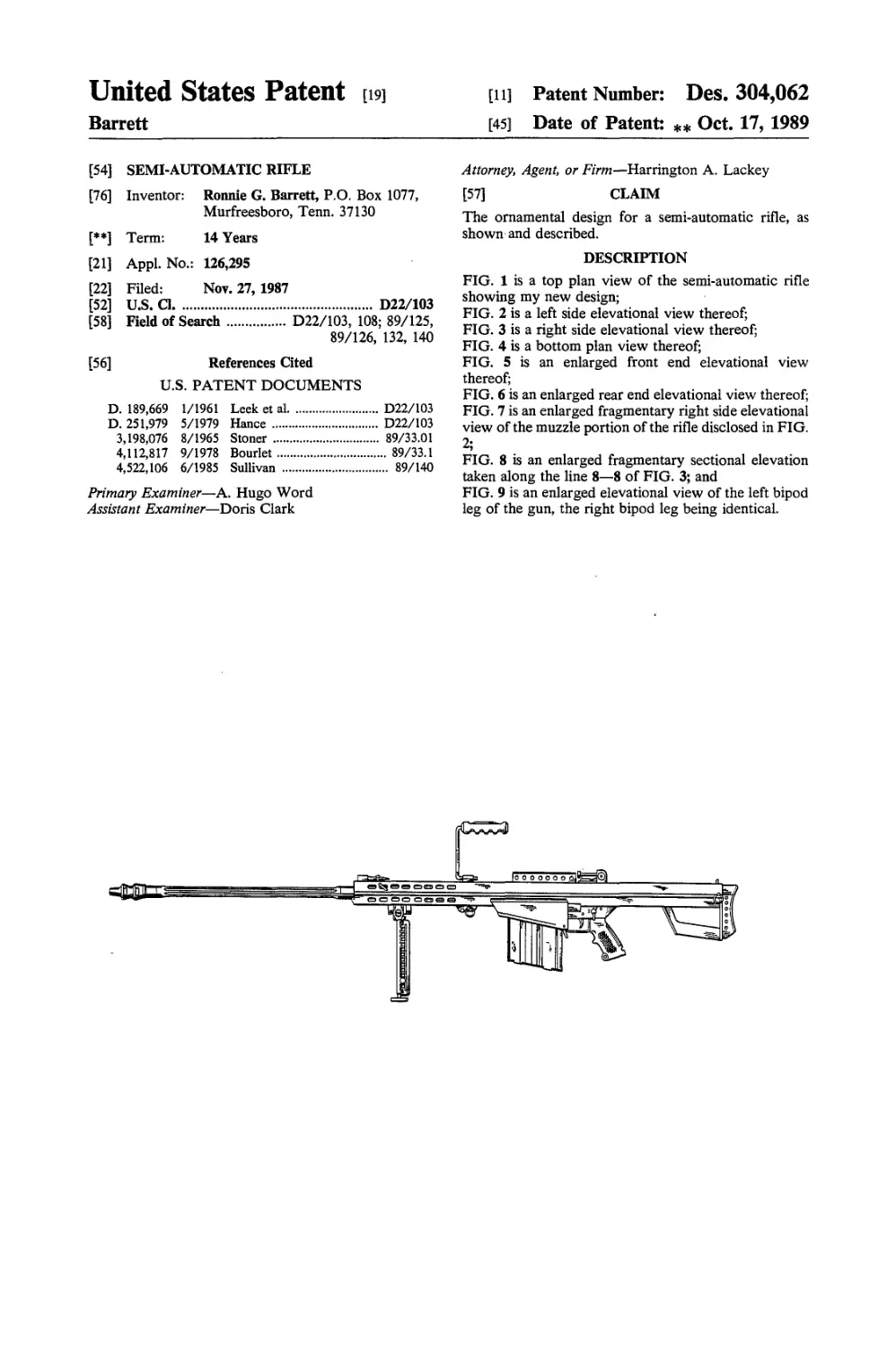
[54] SEMI-AUTOMATIC RIFLE
[76] Inventor: Ronnie G. Barrett, P.O. Box 1077,
Murfreesboro, Tenn. 37130
[**] Term: 14 Years
[21] Appl. No.: 126,295
[22] Filed: Nov. 27, 1987
[52] U.S. a.......................... D22/103
[58] Field of Search......D22/103, 108; 89/125,
89/126, 132, 140
[56] References Cited
U.S. PATENT DOCUMENTS
D. 189,669 1/1961 Leek et al.............. D22/103
D. 251,979 5/1979 Hance .................. D22/103
3,198,076 8/1965 Stoner ................ 89/33.01
4,112,817 9/1978 Bourlet................. 89/33.1
4,522,106 6/1985 Sullivan ................ 89/140
Primary Examiner—A. Hugo Word
Assistant Examiner—Doris Clark
Attorney, Agent, or Firm—Harrington A. Lackey
[57] CLAIM
The ornamental design for a semi-automatic rifle, as
shown and described.
DESCRIPTION
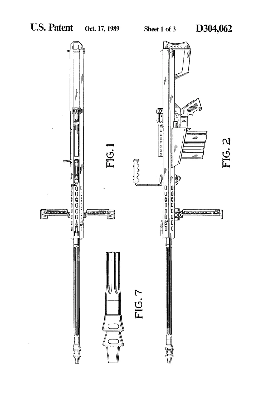
FIG. 1 is a top plan view of the semi-automatic rifle
showing my new design;
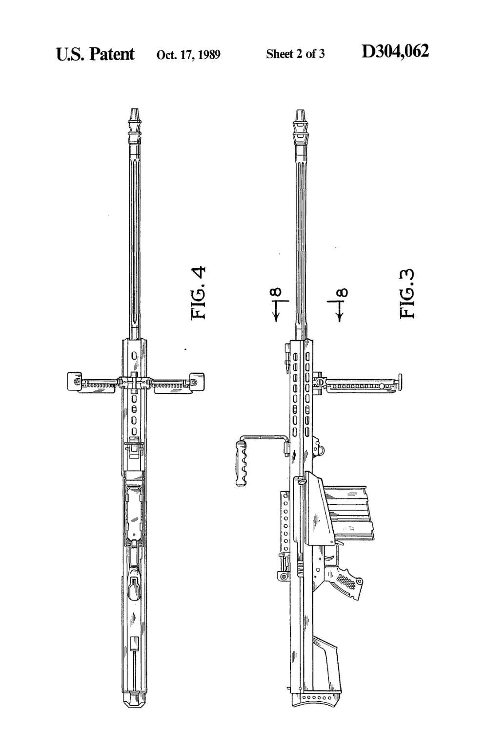
FIG. 2 is a left side elevational view thereof;
FIG. 3 is a right side elevational view thereof;
FIG. 4 is a bottom plan view thereof;
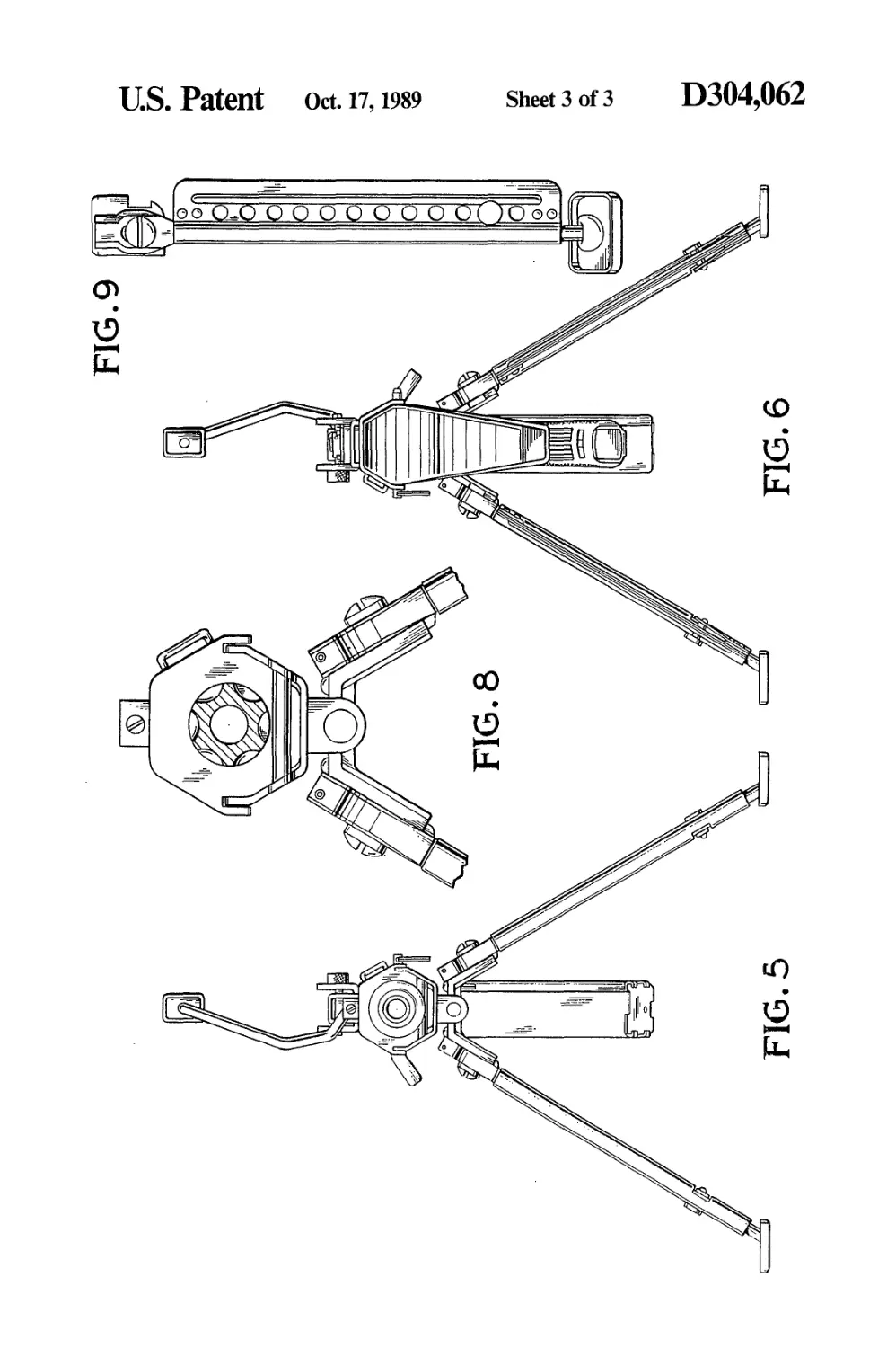
FIG. 5 is an enlarged front end elevational view
thereof;
FIG. 6 is an enlarged rear end elevational view thereof;
FIG. 7 is an enlarged fragmentary right side elevational
view of the muzzle portion of the rifle disclosed in FIG.
2;
FIG. 8 is an enlarged fragmentary sectional elevation
taken along the line 8—8 of FIG. 3; and
FIG. 9 is an enlarged elevational view of the left bipod
leg of the gun, the right bipod leg being identical.
U.S. Patent Oct. 17,1989
Sheet 1 of 3
D304,062
FIG. 2
U.S. Patent Oct. n, 1989
Sheet 2 of 3
D304,062
U.S. Patent Oct. 17,1989
Sheet 3 of 3 D304,062
United States Patent ня
[11] Patent Number:
4,932,148
Barrett
[45] Date of Patent: Jun. 12, 1990
[54] SHOULDER-FIRED SEMI-AUTOMATIC
RIFLE
[76] Inventor: Ronnie G. Barrett, P.O. Box 1077,
Murfreesboro, Tenn. 37130
[21] Appl. No.: 299,665
[22] Filed: Jan. 23, 1989
[51] Int. Cl.5...................F41C 7/02; F41C 19/00
[52] U.S. Cl...........................42/18; 42/69.02;
42/71.01; 42/101; 89/1.42; 89/14.3; D22/103
[58] Field of Search........ 42/6, 18, 22, 69.02,
42/71.01, 72; 89/1.42, 14.3, 33.1, 136, 139, 165,
166; D22/100, 103
[56] References Cited
U.S. PATENT DOCUMENTS
201,524 3/1878 Henry et al.............42/71.01
3,492,912 2/1970 Ashbrook................. 89/14.3
3,623,257 11/1971 Ray ................... 42/71.01
4,651,455 3/1987 Geiser ................... 42/18
FOREIGN PATENT DOCUMENTS
4361 11/1898 United Kingdom ..42/71.01
645751 11/1950 United Kingdom....42/18
Primary Examiner—Stephen C. Bentley
Attorney, Agent, or Firm—Harrington A. Lackey
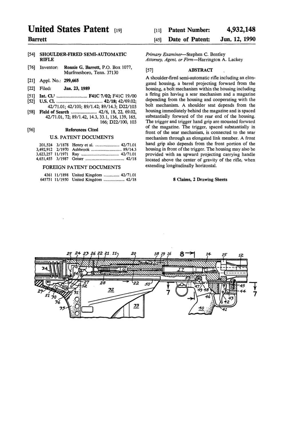
[57] ABSTRACT
A shoulder-fired semi-automatic rifle including an elon-
gated housing, a barrel projecting forward from the
housing, a bolt mechanism within the housing including
a firing pin having a sear mechanism and a magazine
depending from the housing and cooperating with the
bolt mechanism. A shoulder seat depends from the
housing immediately behind the magazine and is spaced
substantially forward of the rear end of the housing.
The trigger and trigger hand grip are mounted forward
of the magazine. The trigger, spaced substantially in
front of the sear mechanism, is connected to the sear
mechanism through an elongated link member. A front
hand grip also depends from the front portion of the
housing in front of the trigger. The housing may also be
provided with an upward projecting carrying handle
located above the center of gravity of the rifle, when
extending longitudinally horizontal.
8 Claims, 2 Drawing Sheets
U.S. Patent Jun. 12,1990
Sheet 1 of 2
4.932.148
FIG. 5
FI^.7
FKJ. 8
U.S. Patent Jun. 12, 1990 Sheet 2 of 2 4,932,148
4,932,148
1 2
5
10
SHOULDER-FIRED SEMI-AUTOMATIC RIFLE
BACKGROUND OF THE INVENTION
This invention relates to a semi-automatic rifle, and
more particularly to a semi-automatic rifle especially
designed for shoulder firing positions.
Semi-automatic rifles, such as the Browning auto-
matic rifle (BAR), the semi-automatic rifle disclosed in
Applicant’s prior patent 4,677,897, and Pat. No.
4,867,040 issued Sept. 19, 1989, are designed to be used
in a prone position. In these automatic rifles, the stock
carrying a rear shoulder pad is fixed to the rear end of
the housing and the front of the housing is usually sup- 15
ported upon a bipod so that the rifle is normally used in
a prone position. In these rifles, both the shoulder pad
and the hand grip and trigger are mounted on the hous-
ing behind the magazine, while the bipod is mounted on
the front of the housing. 20
Although the above-semi-automatic rifles are quite
effective when fired from the prone position, neverthe-
less, their construction and unbalanced weight do not
render the rifle susceptible for use in any other firing
position, and particularly in the standing, kneeling or 25
sitting positions.
SUMMARY OF THE INVENTION
It is therefore an object of this invention to provide in
a semi-automatic rifle of the above-described types a
structure which will facilitate the use of the weapon in
other firing positions than a prone position, and specifi-
cally in a standing, kneeling or sitting position, or any
other position in which the rifle is supported solely by 35
the shoulder and hands of the operator.
A further object of this invention is to provide a
shoulder-fired semi-automatic rifle which is capable of
being fired from a standing, kneeling or sitting position
with little structural change in the internal mechanisms 40
or a conventional semi-automatic rifle normally fired in
a prone position.
A further object of this invention is to provide a
bolt-operated semi-automatic rifle having a housing and
a depending magazine, in which the shoulder pad or 45
seat is located immediately behind the magazine and
substantially forward of the rear end of the housing,
while the trigger and trigger handle grip are spaced
forward of the magazine and provided with linkage
operatively connecting the trigger to the sear mecha- 50
nism for firing the rifle in a standing, kneeling or sitting
position.
Another object of this invention is to provide a shoul-
der-fired semi-automatic rifle in which the trigger is 55
located substantially in front of the sear mechanism and
in which an elongated link mechanism operatively con-
nects the forward trigger to the existing trigger lever in
the rear portion of the housing for firing the rifle.
A further object of this invention is to provide a 60
shoulder-operated semi-automatic rifle in which the
mass of the elements of the rifle including the housing,
barrel, magazine, shoulder seat member and trigger are
optimally balanced about the center of gravity of the
rifle when it extends longitudinally horizontal to facili- 65
tate a single operator supporting the rifle upon his
shoulder for firing in a standing, sitting or kneeling
position.
BRIEF DESCRIPTION OF THE DRAWINGS
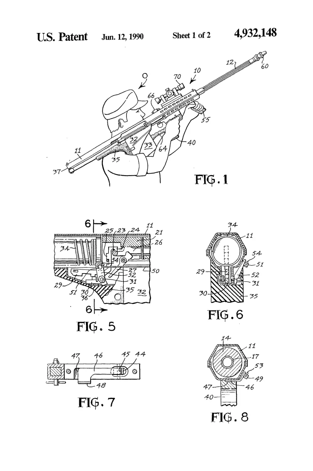
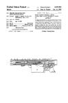
FIG. 1 is a side elevation of a semi-automatic rifle
made in accordance with this invention in an operative
position supported upon the shoulder of an operator for
firing in a standing, sitting or kneeling position;
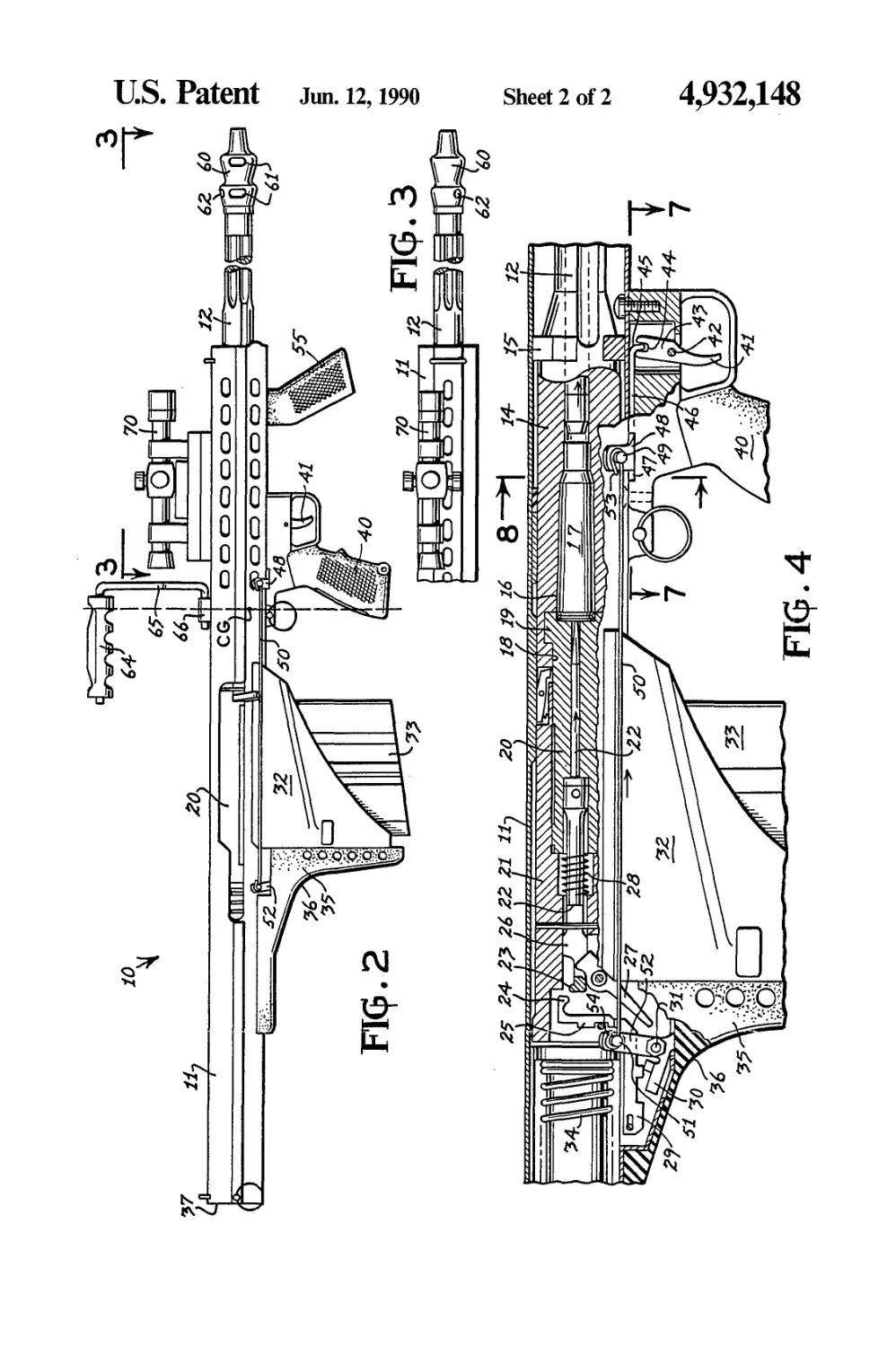
FIG. 2 is an enlarged side elevation of the rifle dis-
closed in FIG. 1, with portions of the barrel broken
away;
FIG. 3 is a fragmentary plan view taken along the line
3—3 of FIG. 2 of the front portion of the rifle, with a
portion of the barrel broken away;
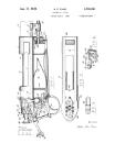
FIG. 4 is an enlarged fragmentary elevation of the
intermediate portion of the rifle housing, with the oper-
ating portions shown in section, and illustrating the
trigger mechanism in a firing position;
FIG. 5 is an enlarged fragmentary sectional elevation
of the the rear portion of the rifle disclosed in FIG. 2,
including the sear mechanism in an inoperative cocked
position;
FIG. 6 is a fragmentary section taken along the line
6—6 of FIG. 5;
FIG. 7 is a horizontal sectional view taken along the
line 7—7 of FIG. 4; and
FIG. 8 is a fragmentary section taken along the line
8—8 of FIG. 4.
DESCRIPTION OF THE PREFERRED
EMBODIMENTS
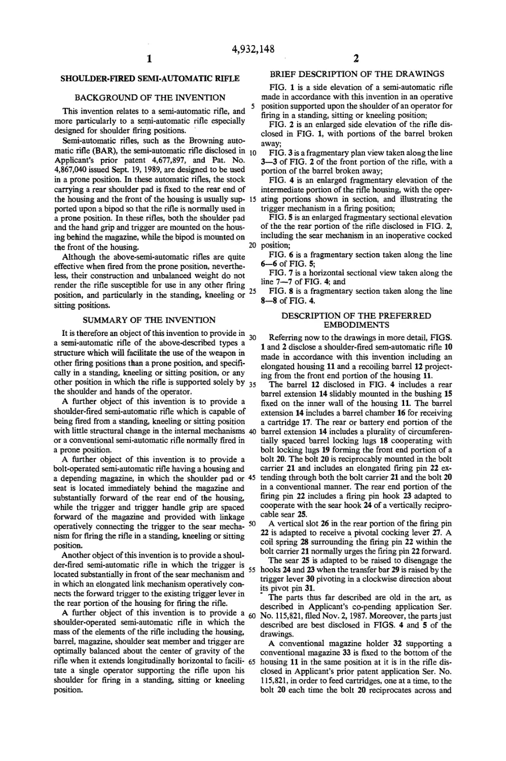
Referring now to the drawings in more detail, FIGS.
1 and 2 disclose a shoulder-fired sem-automatic rifle 10
made in accordance with this invention including an
elongated housing 11 and a recoiling barrel 12 project-
ing from the front end portion of the housing 11.
The barrel 12 disclosed in FIG. 4 includes a rear
barrel extension 14 slidably mounted in the bushing 15
fixed on the inner wall of the housing 11. The barrel
extension 14 includes a barrel chamber 16 for receiving
a cartridge 17. The rear or battery end portion of the
barrel extension 14 includes a plurality of circumferen-
tially spaced barrel locking lugs 18 cooperating with
bolt locking lugs 19 forming the front end portion of a
bolt 20. The bolt 20 is reciprocably mounted in the bolt
carrier 21 and includes an elongated firing pin 22 ex-
tending through both the bolt carrier 21 and the bolt 20
in a conventional manner. The rear end portion of the
firing pin 22 includes a firing pin hook 23 adapted to
cooperate with the sear hook 24 of a vertically recipro-
cable sear 25.
A vertical slot 26 in the rear portion of the firing pin
22 is adapted to receive a pivotal cocking lever 27. A
coil spring 28 surrounding the firing pin 22 within the
bolt carrier 21 normally urges the firing pin 22 forward.
The sear 25 is adapted to be raised to disengage the
hooks 24 and 23 when the transfer bar 29 is raised by the
trigger lever 30 pivoting in a clockwise direction about
its pivot pin 31.
The parts thus far described are old in the art, as
described in Applicant’s со-pending application Ser.
No. 115,821, filed Nov. 2,1987. Moreover, the parts just
described are best disclosed in FIGS. 4 and 5 of the
drawings.
A conventional magazine holder 32 supporting a
conventional magazine 33 is fixed to the bottom of the
housing 11 in the same position at it is in the rifle dis-
closed in Applicant’s prior patent application Ser. No.
115,821, in order to feed cartridges, one at a time, to the
bolt 20 each time the bolt 20 reciprocates across and
148
4
ment or recoil and reaction movement of the barrel 12
upward and the the right.
The rifle 10 is preferably provided with a carrying
handle 64 which is pivotally connected by a handle arm
65 to a swivel joint 66 fixed to the top of the housing 11.
The swivel joint 66 and the carrying handle 64 are
preferably located above the center of gravity CG
when the housing 11 extends horizontally, to facilitate
carrying the rifle 10 in a balanced position.
The rifle 10 is also preferably provided with an elon-
gated glass sight or telescopic sight 70 which is
mounted in front of the handle member 64 and fixed to
the top of the housing 11.
It is thus apparent, particularly from FIGS. 1 and 2,
that all of the elements of the rifle 10, both the conven-
tional elements and the additional elements, are so
spaced and located not only to facilitate the firing of the
weapon 10, but also to provide a substantially balanced
load including the mass of all the elements about the
center of gravity CG. In this manner, the balanced
weights of the parts facilitate the support of the rifle 10
upon the shoulder of the operator 0 for comfort and
improved accuracy of the weapon, particularly in a
standing, sitting or kneeling position.
What is claimed is:
1. A shoulder-fired semi-automatic rifle comprising:
(a) an elongated housing having a rear end portion, a
front end portion, and an intermediate portion,
(b) an elongated barrel mounted within and project-
ing forward from said front end portion of said
housing, and having a rear battery end portion,
(c) bolt means comprising an elongated reciprocable
firing pin having a rear hook, within said interme-
diate portion of said housing and cooperative with
said battery end portion for firing a cartridge
within said battery end portion when said bolt
means is actuated,
(d) a vertically movable sear within said intermediate
portion of said housing for operatively engaging
and disengaging said rear hook,
(e) a pivotally mounted trigger lever mounted in said
housing below said sear,
(f) a pivotally mounted transfer bar operatively en-
gaging said trigger lever and said sear,
(g) a shoulder seat member mounted on and depend-
ing from the intermediate portion of said housing,
said seat member being spaced substantially in
front of said rear end of said housing and immedi-
ately below said sear, said shoulder seat member
being adapted to rest upon the shoulder of an oper-
ator of said rifle,
(h) a trigger hand grip depending from said interme-
diate portion of said housing and spaced in front of
said shoulder seat member,
(i) a trigger pivotally mounted on said housing imme-
diately in front of said trigger hand grip, said trig-
ger being spaced substantially in front of said sear,
(j) an elongated link member extending along said
housing and operatively connecting said trigger
and said trigger lever whereby actuation of said
trigger pivots said trigger lever to disengage said
sear from said rear hook to cause said firing pin to
fire the cartridge in said battery end portion of said
barrel, and
(k) a front hand grip fixed to and depending from said
front end portion of said housing and spaced in
front of said trigger.
4,932,
3
along the top of the magazine 33, and in a conventional
manner.
The bolt carrier 21 is normally urged forward by the
conventional recoil spring 34.
In the semi-automatic rifle 10 made in accordance 5
with this invention, a shoulder seat member 35 includ-
ing an arcuate padded shoulder surface or seat 36 is
fixed to and depends from the bottom of the housing 11
so that it is adjacent and immediately behind the maga-
zine holder 32, as best disclosed in FIGS. 1, 2, 4, and 5. 10
This shoulder seat member 35 is mounted substantially
forward of the rear end 37 of the housing 11 and is
designed to fit the shoulder of the operator 0 (FIG. 1) in
such a manner that the weight of the rifle 10 is more
balanced for support upon the shoulder of the operator 15
0 closer to the center of gravity CG (FIG. 1).
Spaced in front of the magazine holder 32 and in front
of the sear 25 is a trigger hand grip 40 depending from
the housing 11 in the vicinity of the center of gravity
CG and toward the forward end portion of the housing 20
11. Fixed immediately in front of the hand grip 40 is a
trigger 41 pivotally mounted about the trigger pivot pin
42. The upper end portion 43 of the trigger member
above the pivot pin 42 terminates in a bifurcated portion
having a transverse groove 44. 25
Received in the transverse trigger groove 44 is the
hooked front end 45 of an elongated slide member or
slide plate 46 slidably received within a corresponding
recess 47 within the bottom of the housing 11 immedi-
ately above the hand grip 40. Projecting laterally out- 30
board from the slide plate 46 is a transverse connector
ear 48 provided with a connector pin 49 operatively
connected to the looped front end 53 of an elongated
link rod 50. The rear end of the link rod 50 preferably
terminates in a rear loop or looped end portion 54 oper- 35
atively connected to a pin 51 on the free end of a trigger
arm 52, the opposite end of which is fixed to the trigger
lever 30 for simultaneous rotation about the pivot pin
31. The front looped end or loop 53 may cooperate with
the front connector pin 49 by extending through a cor- 40
responding aperture (not shown) in the pin 49. The rear
end loop 54 may cooperate with the rear connector pin
51 in the same manner as the front looped end 53 coop-
erates with the front connector pin 49.
Mounted and spaced in front of the trigger 41 is a 45
front hand grip 55 affixed to and depending from the
front end portion of the housing 11. The front hand grip
55 is designed to be gripped by the operator’s hand
which is not actuating the trigger 41. As disclosed in
FIG. 1, the right-handed operator О grips the trigger 50
hand grip 40 with his right hand and the front hand grip
55 with his left hand, while the shoulder seat member 35
rests upon the right shoulder of the operator 0. As dis-
closed in FIG. 1, the rifle 10 is substantially balanced
upon the operator’s right shoulder and both hands to 55
facilitate firing in the standing, kneeling, or sitting posi-
tion.
The front end portion of the barrel 12 may be pro-
vided with a muzzle brake 60 having the usual side gas
ports 61. However, as disclosed in FIG. 3, in order to 60
neutralize the kick, reaction or the recoil of the rifle 10
upward and to the right, when fired, an additional gas
port 62 is formed in the muzzle brake 60 above the
barrel 12, when in a horizontal position, and to the right,
when the observer is looking forward. In other words, 65
the gas port 62 is mounted in an orientation at one o’-
clock when looking in the forward direction. Gas dis-
charged through this port tends to neutralize the move-
4,932,
5
2. The invention according to claim 1 in which said
trigger has an upper end and said elongated link mem-
ber comprises an elongated forward slide member hav-
ing a front end portion operatively connected to said
upper end of said trigger, an elongated link rod having 5
front and rear ends, said front end of said link rod being
operatively connected to said slide member and said
rear end of said link rod being operatively connected to
said trigger lever.
3. The invention according to claim 2 further com- 10
prising a link arm fixed to said trigger lever for pivotal
movement therewith, said rear end of said link rod
being operatively connected to said link arm.
4. The invention according to claim 3 in which said
slide member further comprises an ear projecting later- 15
ally from said slide member and a connector member
operatively connecting the front end of said link rod to
said ear.
5. The invention according to claim 1 further com-
prising a magazine fixed to and depending from the 20
148
6
intermediate portion of said housing and cooperative
with said bolt for feeding cartridges to said bolt means,
said magazine being located immediately in front of said
shoulder seat member and spaced behind said trigger
hand grip.
6. The invention according to claim 5 in which said
housing includes a center of gravity, and further com-
prising a carrying handle member fixed to said housing
for upward projection in the vicinity of said center of
gravity.
7. The invention according to claim 6 further com-
prising an elongated sight member fixed to and project-
ing upward from said housing in front of said carrying
handle member.
8. The invention according to claim 1 further com-
prising a muzzle brake on the front end portion of said
barrel, and a gas port in said muzzle brake disposed
above and to the right of said barrel looking forward.
*****
25
30
35
45
50
55
60
65