/
Tags: weapons military affairs patent
Year: 1907


Text
No. 853,715.
PATENTED MAY 14, 1907.
M. MONDRAGON.
FIREARM.
APPLICATION PILED AUG. 8, 1904.
Ко. 853,715.
PATENTED MAY 14, 1907.
M. MONDRAGON.
FIREARM.
APPLICATION PILED AUG. 8, 1904,
No. 853,715.
PATENTED MAT 14, 1907.
M. MONDRAGON.
FIREARM.
APPLICATION PILED AUG, 8, 1904.
8 SHEETS—SHEET 3.
Ко. 853,715.
PATENTED MAY 14, 1907.
M. MONDRAGON.
FIREARM.
APPLIOATIOH PILED AUG. 8, 1904.
8 SHEETS-SHEET 4.
No. 853,715.
PATENTED MAY 14, 1907.
8 SHEETS—SHEET 6.
M. MONDRAGON.
FIREARM.
APPLICATION FILED AUG. 8, 1904.
*
4
3м ven tot:
^^1сиссаЛ
«J
s
"3
«I
Os
"3
$
43
4i
:«
! Si
I 4
u
I Nt
Mo. 853,715.
PATENTED MAY 14, 1907.
M. MONDRAGON.
FIREARM.
APPLICATION PILED AUG. 8, 1904,
8 SHEETS—SHEET 6.
No. 853,715.
PATENTED MAY 14, 1907.
M. MONDRAGON.
FIREARM.
APPLICATION FILED AUG. 8, 1904.
8 SHEETS-SHEET 7.
No. 853,715.
PATENTED MAY 14, 1907.
M. MONDRAGON.
FIREARM.
APPLIOATIOH PILED AUG. 8, 1904.
8 SHEETS-SHEET 8.
UNITED STATES PATENT OFFICE.
MANUEL MONDRAGON, OF TACUBAYA, MEXICO.
FIREARM.
No. 853,715. Specification of Letters Patent. Patented May 14,1907.
Application filcl August 8,
To all whom it may concern: '
Be it known that I, Manuel Mondragon,
a citizen of the Republic of Mexico, residing j
at Tacubaya, in the Federal District, Mexico, ,
5 have invented certain new and useful Im- I
provements in Firearms, of which the follow- |
ing is a specification. |
„ My present invention pertains to improve-
ments in automatic firearms, and relates I
io more particularly to that class generally
known as or styled “gas-operated”, though
the arm is equally adapted to be operated
manually, either яя я dmde-loader or a re-
peater.
15 The invention is illustrated in the accom-
panying drawings, in which:
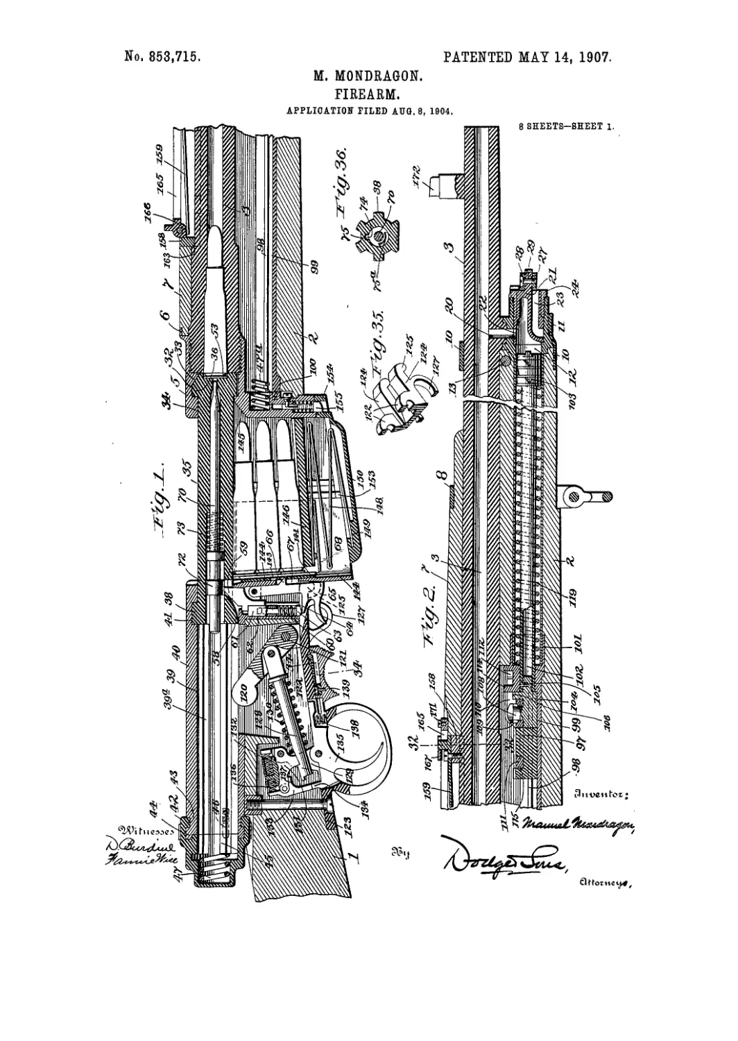
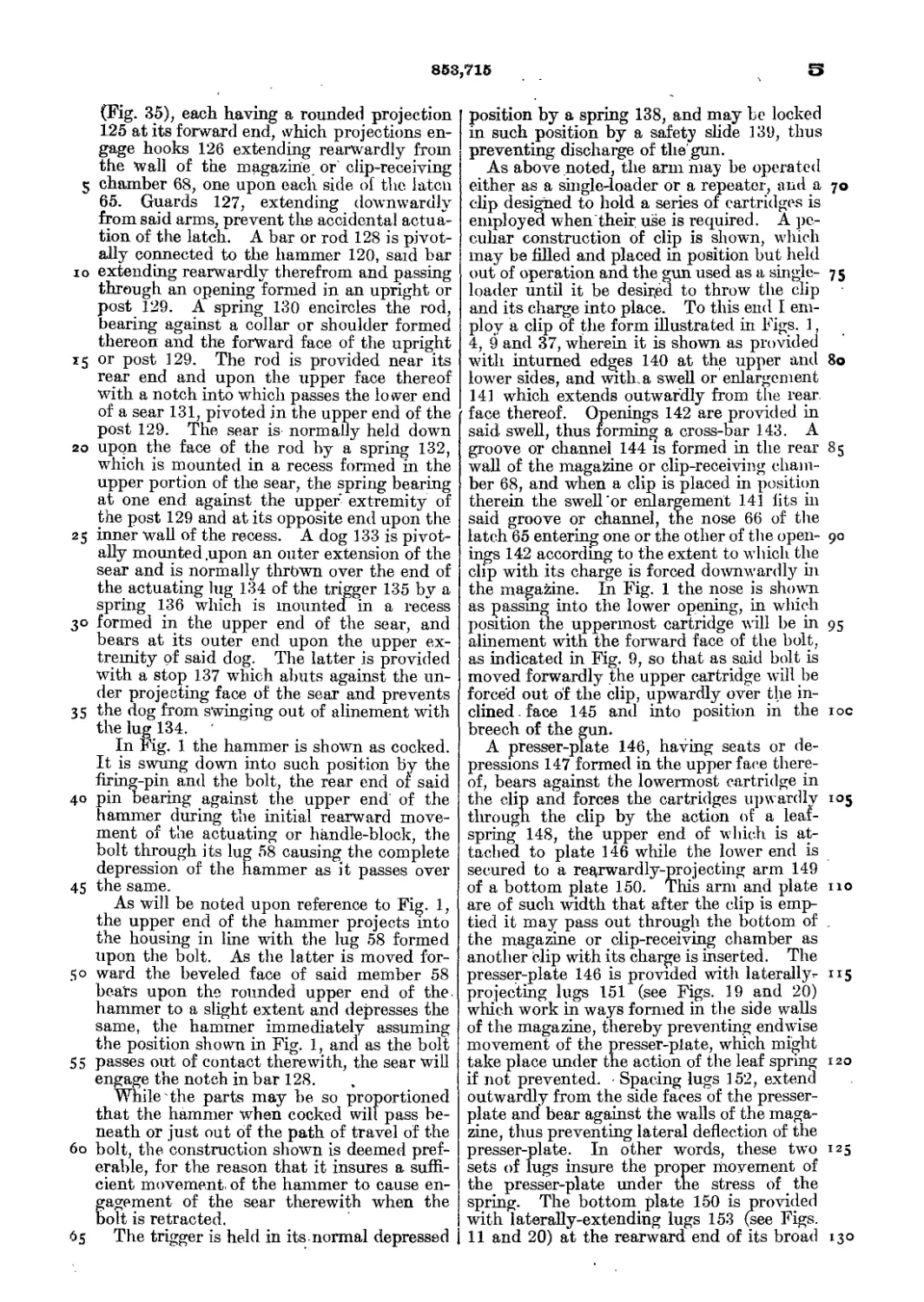
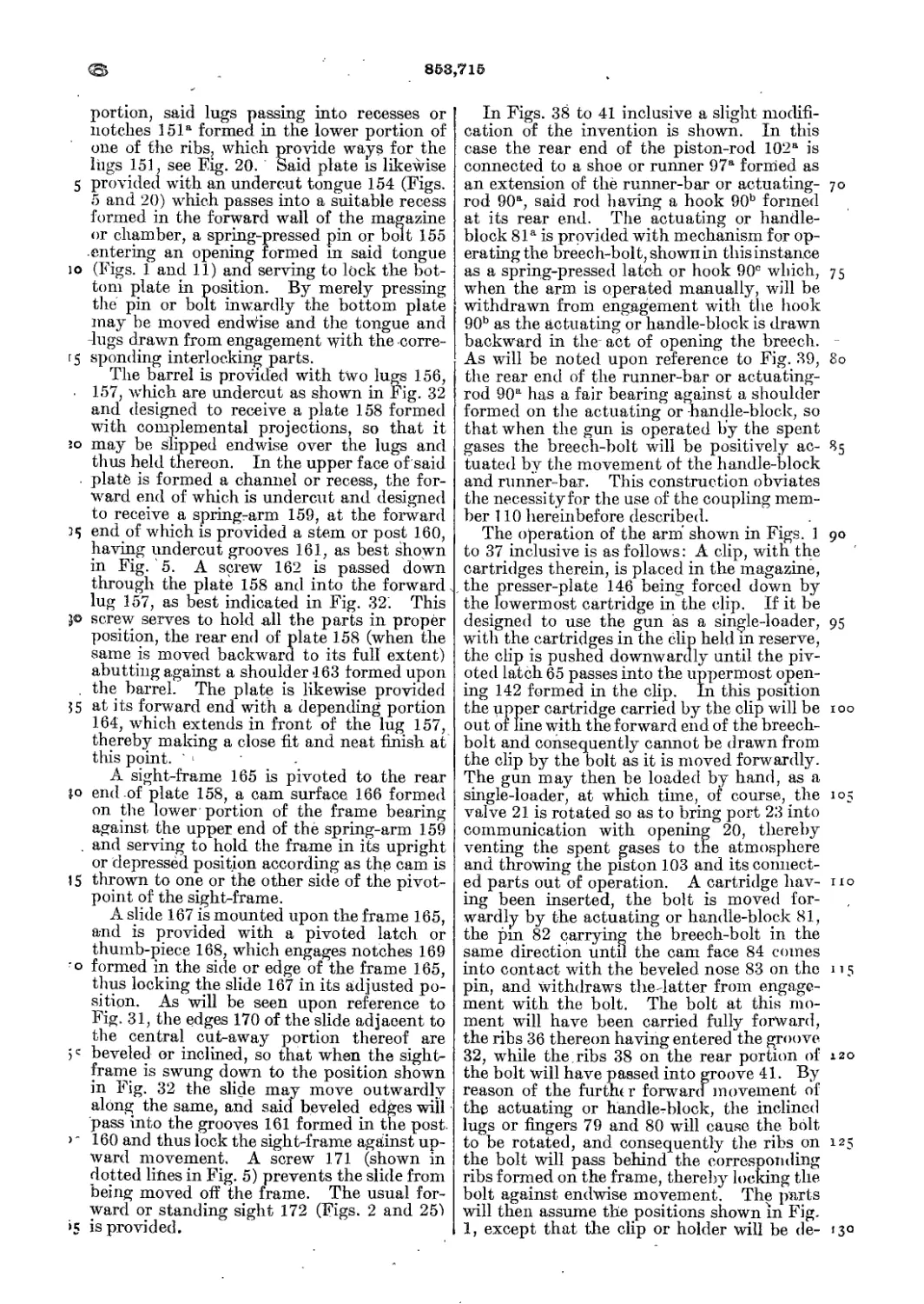
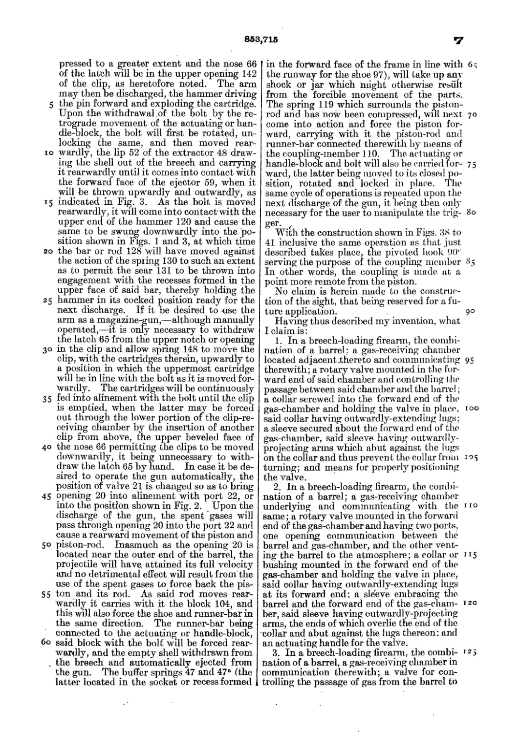
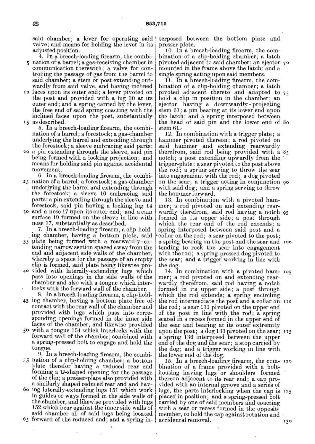
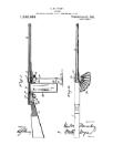
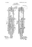
Figure 1 is a longitudinal vertical sectional
view of the rear portion of the arm; Fig. 2 a
similar view, showing the forward portion of
го the same, and in fact being a continuation of
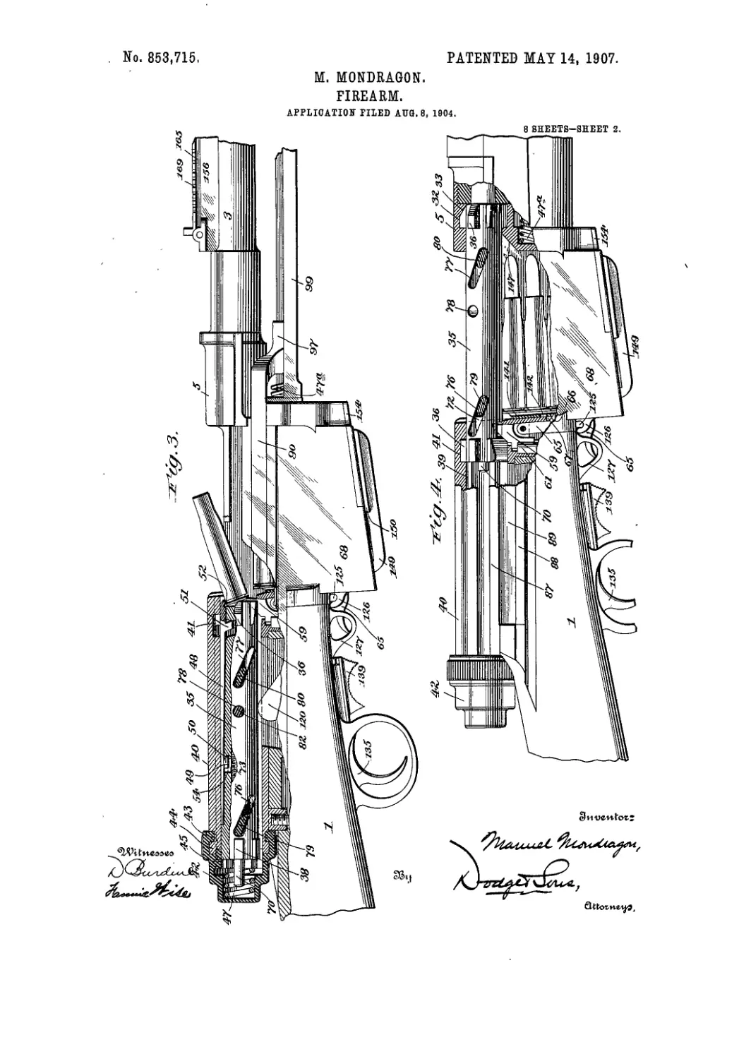
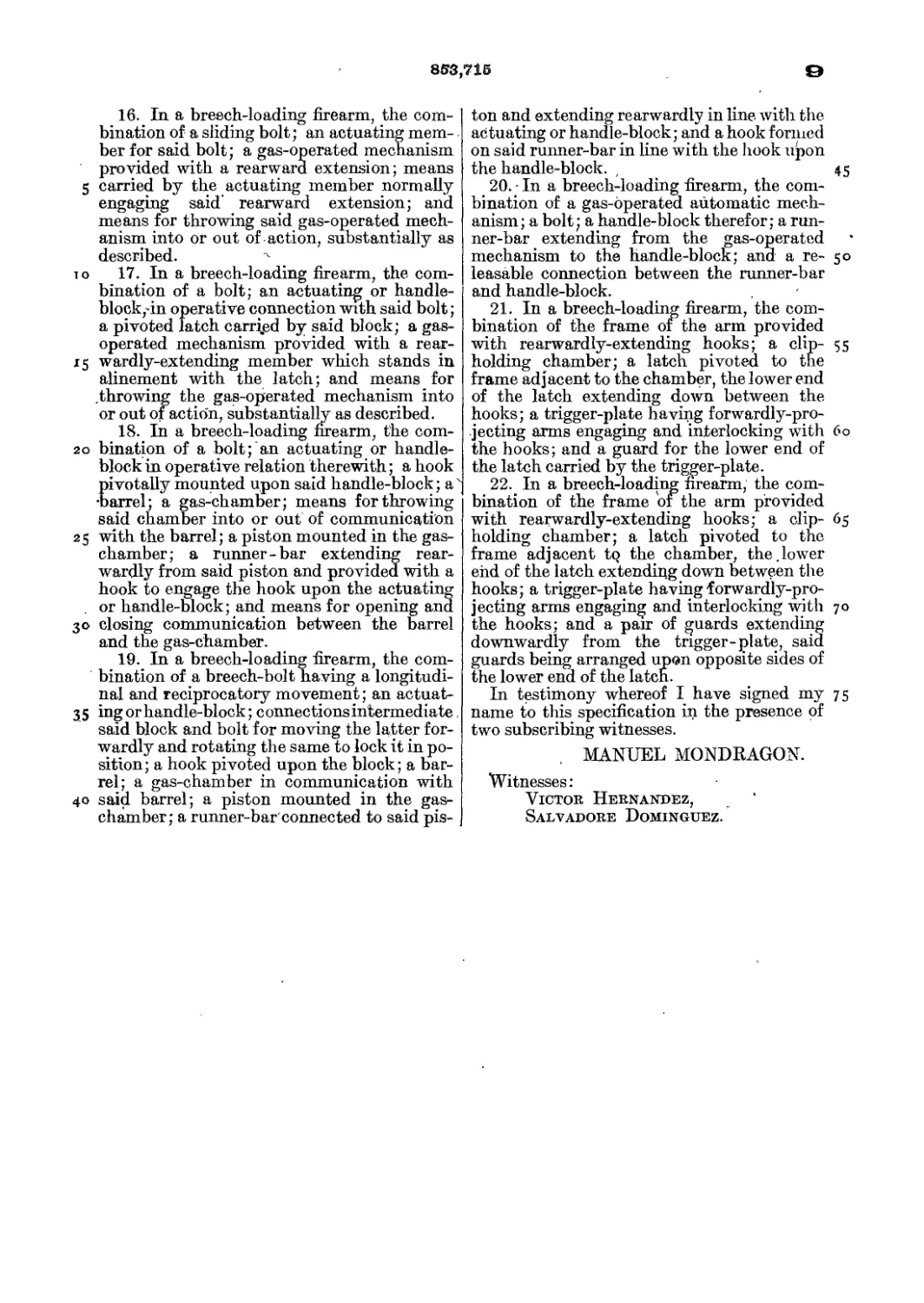
the arm disclosed in Fig. 1; Fig. 3 a side ele-
vation of the arm, with portions thereof
broken away, the hreech-bolt being shown
partly in section and the housing for the
25 same wholly in section; Fig. 4 a similar view,
with the breech-bolt moved forward and
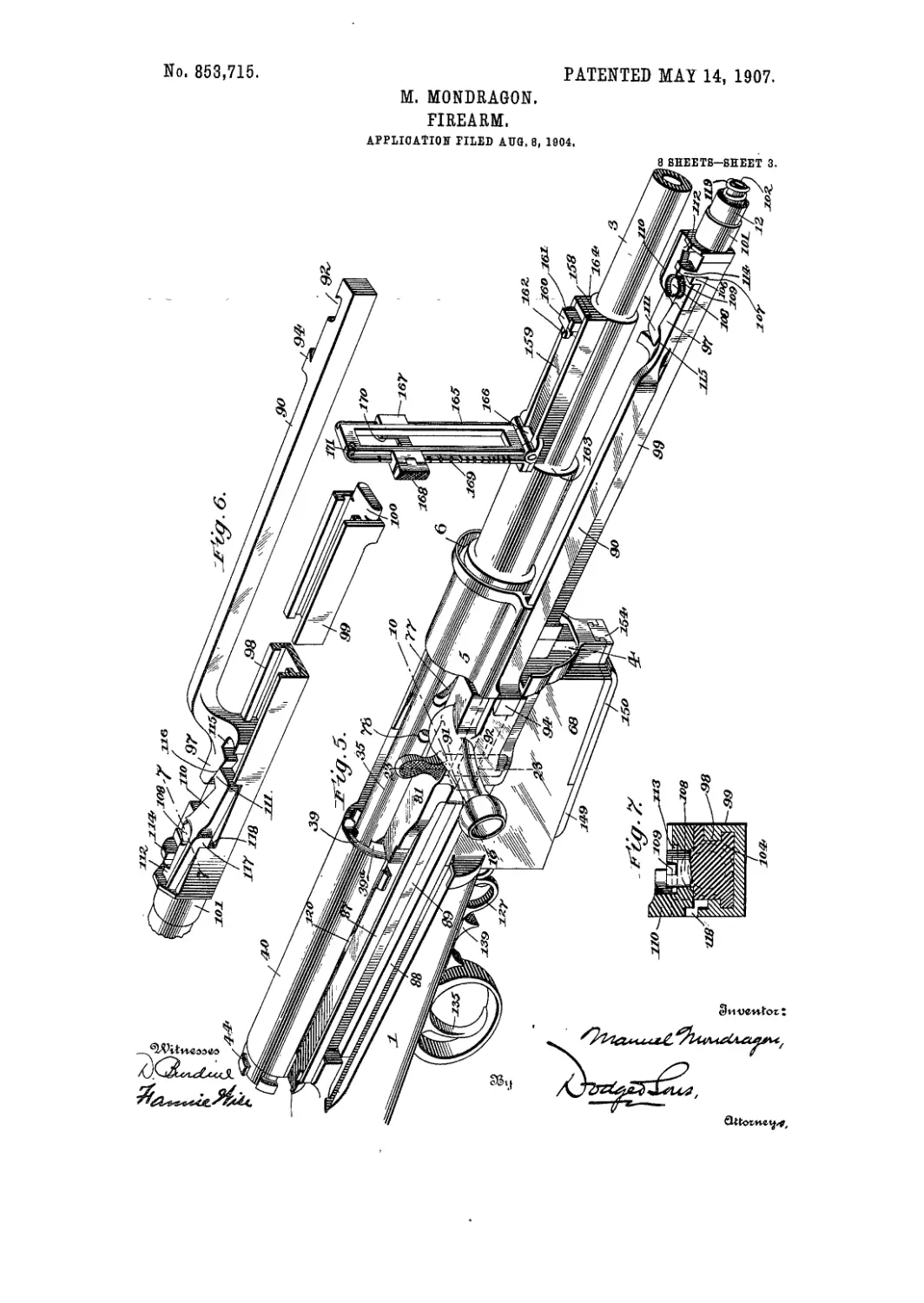
locked in position ready for firing; Fig. 5 a
perspective view of the operative mechanism
of the gun, the forestock being omitted; Fig.
30 6 r perspective view of the runner-bar or ac-
tuating-rod and its connections, seen from the |
side opposite to that shown in Fig. 5'; Fig. 7 a
vertical transverse sectional view on the line
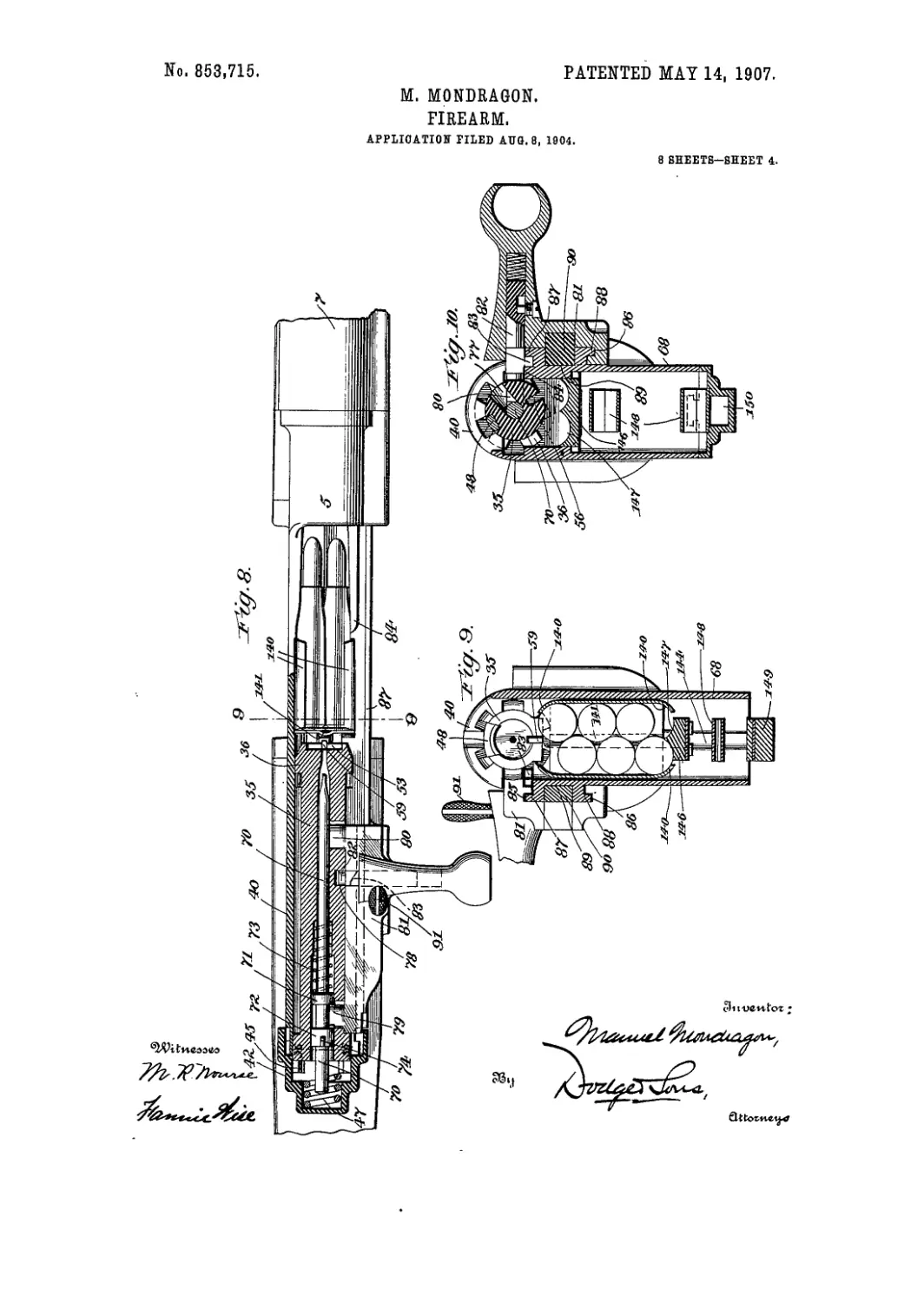
7—7 of Fig. 6; Fig. 8 a longitudinal sectional
35 view of the bolt, showing the parts in their
retracted position, the actuating or handle-
block being shown in full lines; Fig. 9 a ver-
tical sectional view, taken on the line 9—9 of
Fig. 8-; Fig. 10 a similar view on the line 10—
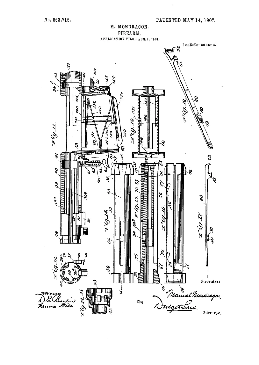
40 10 of Fig. 5; Fig. Ila vertical sectional view
showing the magazine, the ejector and the
housing for the breech-bolt; Fig. 12 an end
elevation of the housing; Fig. 13 a longitudi-
nal sectional view of the cap or closure for
45 the rear end of the housing; Fig. 14 a top
plan view of the bolt; Fig. 15 a longitudinal
sectional view, taken on the line 15—15 of
Fig. 14; Fig. 16 a plan view of the bolt as
seen rrom the under side; Fig. 17 a side eieva-
50 tion of the extractor; Fig. 18 a persyecti <:s j
view thereof as seen from the under зЦе or !
face; Fig. 19 a horizontal sectional new,
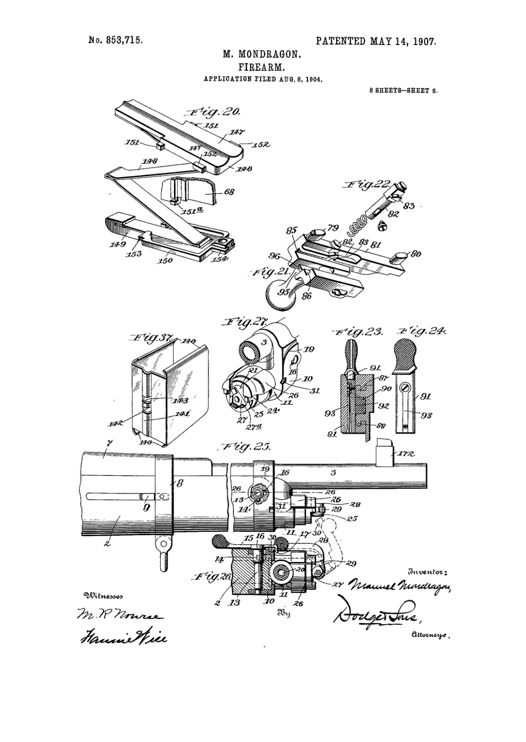
taken on the line 19—19 of Fig. 11; Fig. 20 a
perspective view of the bottom plate of the
55 magazine, the spring and-elevating-plate for
1904. Serial No. 219,989.
the cartridges; Fig. 21 a perspective view of
the actuating or handle-block; Fig. 22 a per-
spective view of the locking-pin and its re-
lated parts; Fig. 23 a vertical sectional view,
taken on the line 23—23 of Fig. 5; Fig. 24 a 6c
side elevation of the locking-pin which con-
nects the actuating or handle-block to the run-
ner-bar or actuating-rod; Fig. 25 a side eleva-
tion of the forward portion of the gun, showing
the forestock in position; Fig. 26 a horizontal 65
sectional view on the line 26—26 of Fig. 25;
Fig. 27 a perspective view of the forward por-
tion of the gun, the barrel being broken away
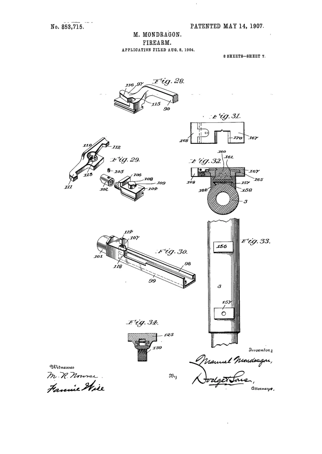
and the valve-handle omitted; Fig. 28 a per-
spective view of the forward end of the run- 70
ner-frar or actuating tod; Fig. 29 a similar
view of the latch and the block upon which
it is pivotally mounted; Fig. 30 a perspective
view of the forward portion of the runway
or guiding member for the actuating-rod or 75
runner-bar; Fig. 31 a plan view of the sight-
slide; Fig. 32 a vertical transverse sectional
view on the line 32—32 of Fig. 2; Fig. 33 a
top plan view of a portion of the barrel, show-
ing the lugs which hold the sight; Fig. 34 а Г->
vertical sectional view on the line 34—° L of
Fig. 1; Fig. 35 a detail perspective view of
the forward portion of the trigger-plate;
Fig. 36 a sectional view on the line 36—36 of
Fig. 8 of the bolt and firing-pin; Fig. 37 a per- 85
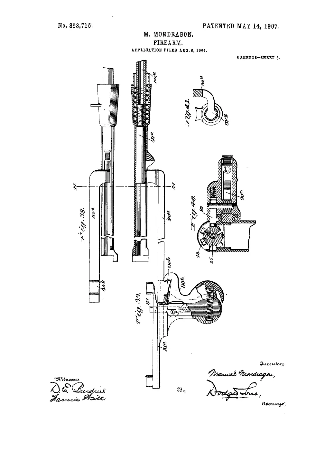
spective view of the cartridge-clip; Fig. 38 a
side elevation of a modified construction of
the runner-bar and its connections; Fig. 39 a
horizontal sectional view thereof, showing a
modified form of actuating or handle-block. 90
used in conjunction with said runner-bar;
Fig. 40 a vertical sectional view, taken
through the handle, and showing the connec-
tion thereof with the breech-bolt; and Fig.
41 a transverse sectional view, taken on the 95
line 41—41 of Fig. 38.
My present invention, except as to certain
details of construction, is an improvement
upon that set forth in my со-pending appli-
cation filed on or about the 6th day of Mav, 100
1902, Serial No. 106,177. "
The main object of the invention is to per-
fect certain deto.'s of the structure shown in
the application ao^ve referred to, and to ren-
der the arm generally more efficient. 105
The improvements will be noted in the fol-
lowing description, and those features which
are essentially novel and not modifications of
the former construction will likewise be set
forth in detail. 11 о
853,715
Referring to Figs. 1 to 37 inclusive of the .
drawings, 1 denotes the stock of the gun; 2
forestock, the and 3 the barrel, the forestock
being cut away at its rear end (see Fig. 1) and
5 fitting into a recess or socket 4 (Figs. 1 and 5)
formed in the forward under face of the
frame 5. The upper front face of said frame
is provided with a recess or socket 6, for the
reception of the rear end of the upper mem-
to ber 7 of the forestock. The two portions of
the forestock are held in position around the
barrel, and the member 2 about the gas-
chamber (hereinafter referred to), by a sleeve
or collar 8, which slips over said parts and is
15 held in place by spring-catches 9 (see Fig.
25), which are recessed in the sides of the
member 2. A second sleeve or collar, 10,
covers the forward end of the member. 2. A
projection 11, formed on said member 10 fits
20 around the outer end of the gas-receiving cyl-
inder or chamber 12. Said sleeve or collar
10 is retained in its position by a through-
pin 13 (see Figs. 2 and 26), the pin being re-
duced at one end and entering a hole formed
25 in the sleeve or collar, while the other end is
somewhat enlarged and is provided with a
laterally-extending lug or projection 14,
which, when the pin or key is turned by the
lever 15 attached thereto, passes beneath the
30 inner face of the collar 10 and out of line with
the slot 16 formed in said member 10 through
which the lug or projection passed when the
pin was inserted in place.
The lever or handle 15 is provided with an
35 inwardly-projecting nose 17, which' passes
over a cam or raised face 19 formed upon the
sleeve or collar 10 &s the pin is rotated and
the lever 15 carried from a vertical to a hori-
zontal position. When in the latter position
40 the nose 17 will have passed off the cam face
and the pin be held against rotation except
upon the application of force to the outer end
of lever 15.
The gas-chamber 12 is in communication
45 with the barrel near its outer end through an
opening 20 (Figs. 2 arid 26), the passage of
the gas through said opening being controlled
by a rotary valve 21, provided with a port 22,
which permits communication between the
50 valve and the gas-chamber, as indicated in
Fig: 2. The valve is also provided with a
second port or opening, 23, which, when the
valve, is rotated to a position opposite that
shown in Fig. 2, will be in communication
5 5 with the atmosphere, and communication be-
tween the gas-chamber and barrel will be cut
off.
In order to keep the valve to its seat in the
forward end of the gas-chamber, I employ a
60 bushing or collar 24, which is screwed into
the end of said chamber (as best illustrated
in Fig. 2), s aid collar b eing pro vided with lugs
25, which bear against the, under faces of the
outwardly-projecting members or arms 26
65 of the sleeve or collar 10. These arms 26,
therefore, prevent the bushing 24 from ro-
tating so long as the sleeve or collar is held in
place, and consequently the valve is always
retained in proper position within the for-
ward end of the gas-chamber. 7 о
The valve is provided with a stem 27, to
which is pivotally attached an L-shaped
lever 28. This lever carries a spring 29,
which bears upon the inclined faces on the
outer end of the stem 27, serving to hold the 75
lever depressed, as in the position showm in
full lines in Fig. 26, or in an elevated position,
as indicated m dotted lines in said figure.
The stem 27 is provided with a lateral pro-
jection 27a or made of such width that the 80
valve may be turned through but half a revo-
lution, since the stem or projection comes
into contact with one or another of the arms
26, the arrangement being such that one or
the other of the ports 22, 23 will be brought 85
into alinement with- the opening or passage
20. The outer end of lever 28 is provided
with a lug or finger 30 (Fig. 26) which will
enter one or the other of two oppositely-
disposed seats or depressions 31 formed in 93
the sleeve or collar 10. Thus it will be seen
that the valve will always be brought to and
maintained in proper position.
The rear end of the barrel 3 is secured to
the frame, as shown in Fig. 1, the frame be- 95
ing made sufficiently heavy at this point to
be provided twith a groove or channel 32,.
having an inclined face 33 adjacent to the
end of the barrel, and likewise provided with
a series of ribs 34 (Fig. 11). The breech- ио
chamber thus formed is designed to receive
the forward end of the breech-bolt 35, said
bolt being formed at its forward end with
ribs 36, haying inclined faces 37, ribs 36 pass-
ing in between ribs 34 and fitting within the 105
groove 32 and against the face 33 when the
bolt is shoved to place and rotated, as here-
inafter described. The rear end of the bolt
is provided with a series of laterally-extend-
ing ribs or projections 38, which work in cor- no
responding grooves 39 formed in the housing
on rearward extension 40 of the frame. The
forward end of said housing is provided with
an internal groove or channel 41, see Fig. 3,
into which ribs 38 pass when the breech-bolt 115
is moved forward to the position shown in
Figs. 1 arid 4. The rear end of the housing
is closed by a cap 42, provided with lugs 43,
which interlock with similar lugs 44 formed
upon the rear end of the housing, as best 120
shown in Fig. 11. The cap is also provided
with a second series of lugs 45, which when
the cap is in place and rotated come into
alinement with ribs 39a, intermediate the
grooves 39 formed in the housing 40. A 125
spring-pressed pin 46 is mounted in one of
said ribs 39a and takes into a socket or recess
formed in the face of the corresponding lug
45. This socket or recess is shown in dotted
lines in Fig. 1. 130
863,715
8
A coiled spring 47 (Figs. 3 and 8) is placed
in the' cap 42, and is in direct alinement with
the rear end, of the breech-bolt, serving as a
buffer therefor.
; The breech-bolt is provided with an ex-
tractor 48, best shown in Figs. 14, 15, 17 and
18. Said extractor comprises a spring-plate
having a downwardly-depending lug 49 near
its rear end, which lug has a lip 50 formed
io thereon. A second lug or finger, 51, is
formed upon the under face of the extractor
near its outer end. Said end is.widened, as
clearly shown in Figs. 14 and 15, and is pro-
vided with a downwardly-projecting lip 52
15 which, when the extractor is in its normal
position, lies within a recess 53 formed in the
forward end of the breech-bolt, and into
which the head of the shell or cartridge pro-
jects when the bolt is closed, as shown in
20 Figs. 1 and 4.
A recess is formed in the outer face of the
breech-bolt for the reception of the extractor,
and there is an elongated opening 54 (Figs.
14 and 15) in the bolt in line with said recess,
25 a second opening 55 being also provided at its
forward end.
As will be seen upon reference to Fig. 17,
the - extractor is curved or bowed slightly,
and when put in position the lug 49 passes
30 into the opening 54 and lug 51 enters opening
55. A slight downward and forward pres-
sure upon the extractor will then cause the
lip 50 to pass into a socket 54a, while at the
same time the lug 51, which is given a slight
35 forward inclination, will bind against the for-
ward wall of the opening 55. When the
parts are thus positioned, the rear end of the
extractor will have passed down into the re-
cess and the body thereof will lie flush with
40 the outer face of the bolt. The lip 50 locks
the extractor in place, but by reason of the
inclination given to the opening 55 and lug
51, lip 52 will pass over the end of the car-
tridge and into the groove formed around
45 the same as the bolt is pushed to place or;
closed.
- The bolt, as will be seen upon reference
more particularly to Figs. 15 and 16, is pro-
vided with a groove or channel 56, extending
50 longitudinally thereof from the forward end
and terminating in a lateral opening or en-
largement 57, just in rear of the forwardly-
beveled or broad-faced projection or lug 58.
The groove 56 is designed to receive the up-
55 per end of the ejector 59 (see Figs. 1, 3, 4, 9
and 11), the forward face of which is in a ver-
tical plane, while the rear face is inclined.
When the bolt is moved to its forward po-
sition, or that shown in Fig. 4, and is rotated
60 in the manner hereinafter described to lockit
in place, the upper end or nose of the ejector
will pass into tne enlargement or opening 57.
The ejector is held in its upright position by
a spring 60 (see Fig. 11) which bears upon.
65 the lower end of a stem 61, mounted in a
downwardly-projecting sleeve or chamber
62, said stem being made hollow for the re-
ception of the stem of a pin 63, the head of
which pin bears upon a shoulder 64 on a piv-
oted latch or lever 65. This latch is pro- 70
vided with a nose or projection 66, which ex-
tends through an opening 67 into the maga-
zine or clip-receiving chamber 68. The pur-
pose of this latch will be hereinafter set
forth. Spring 60 thus serves to keep the 75
ejector in its elevated position, and at the
same time to throw the latch forwardly and
project the nose 66 through the opening 67.
A firing-pin 70 is centrally mounted in the
bolt, said pin having two collars 71, 72 80
formed thereon. A spring 73 is interposed
between the forward face of collar 71 and a
shoulder formed on the bolt, said spring
tending normally to force the pin back to the
position shown in Fig. 8. 85
A lug 74, shown in Figs. 8 and 36, works in
a slot or groove 75 formed in the inner face of
the bolt (see Fig. 15), said lug serving to
properly position the firing-pin in the bolt
and bring a cut-away portion 75a in the 90
lower face of the collar 72 into alinement
with the opening 57, to accommodate the
upper end of the ejector 59.
The bolt is provided upon its side face with
two helical or spirally-disposed openings 76 95
and 77, and witn a socket or depression 78.
Inwardly-projecting lugs or fingers 79 and 80,
preferably formed as integral parts of the ac-
tuating or handle-block 81, extend into the
openings 76, 77, and a spring-actuated pin iuo
82, carried by the block, nts in the socket or
depression 78 until the bolt nearly reaches
the limit of its forward movement. The pin
is also provided with a beveled nose or lug 83,
standing in the path of a cam 84 (Fig. 8) 105
which serves to force the pin inwardly, and
thus withdraw the same from, the socket or
depression 78, thereby permitting the bolt to
be freely acted upon by the lugs or fingers 79,
80 as the bolt approaches the limit of its for- 110
ward movement. By reason of the inclina-
tion of the openings 76, 77 and fingers 79, 80,
the bolt will be given a rotary movement af-
ter it has reached the limit of its forward
travel, the actuating or handle-block 81 115
moving forward a slight distance independ-
ently of the bolt after the pin 82 has been re-
leased, thereby permitting the lugs to travel
through the length of the openings and caus-
ing the rotation just noted. This rotation 120
will cause the locking of the lugs of the bolt
behind the lugs formed on the frame. The
.lug 79 is provided with a squared face upon
its rear side, which has its bearing against
the forward face of the collar 72, said lug at 125
all times extending between the. collars 71
and 72.'
As; the bolt is moved forward, the lug 79
holds the firing-pin and bolt in the position
shown in Fig. 8, but as the bolt reaches its 130
863,715
seat and is locked therein, the lug advances
the firing-pin to the position shown in Fig. 1,
and the gun is then ready for firing.
The actuating or handle-block is provided
5 with oppositely-disposed recesses or ways
85, 86, which embrace tracks or ways 87, 88
formed upon one side of the frame. A track
or channel 89 is formed upon the outer side
of the frame, (intermediate the tracks or
to ways 87, 88,) in which works the rear end'of
a runner-bar or actuating-rod 90, shown
most clearly in Figs. 5 and 6. Said rear end
is connected to the handle or actuating block
81 by a pin 91 (see Figs. 5, 23 and 24) which
15 passes down through an opening formed in
the block and into a socket or recess 92 in the
side face of the runner bar. The pin 91 is
provided with a spring-finger 93, the free end of
which binds against an inclined face formed at
го the lower end of a recess in the actuating or
handle-block and serves to keep the pin in
position. The runner-bar or actuating-rod
is provided with a lug or projection 94, which
is undercut (as best shown in Fig. 6), said lug
25 fitting into a recess 95 (see Fig. 22) and over-
lying a correspondingly-beveled face 96, thus
serving to more securely lock the runner-
bar and actuating or handle-block together.
The forward end of the runner-bar is curved
30 downwardly and inwardly beneath the bar-
rel, and is provided with a shoe or foot-piece
97, having recesses or ways formed in its side
face which work in conjunction with guides
or tracks 98 formed upon the side walls of a
35 supporting and guiding member 99. The
rear end of said member 99 is provided with
a lug 100, which fits into a corresponding re-
cess formed in the front face of the frame of
the gun. The forward end of the member 99
40 is provided with a tubular extension 101,
which makes close telescoping connection
with the rear end of the gas-chamber or cyl-
inder 12, as is best shown in Fig. 2. Mount-
ed within said gas-chamber or cylinder is a
45 piston-rod 102, carrying at its forward end a
piston 103, preferably composed of a series
of split rings and interposed washers, which
form a close joint with the gas-chamber.
The rear end of the piston-rod extends
50 through an opening formed in the head of the
supporting member 99 and is connected to a
block 104, shown in detail in Fig. 29. The
rod is screwed upon a threaded stud carried
by the block, being held in position by a set-
55 screw 105. The block is also formed with
guides or ways which work in conjunction
with the trafeks 98 of the supporting member
99. It is further provided with an upstand-
ing wall 106 at its forward end, which, when
60 the piston is at theiforward limit of its move-
ment, abuts against the upright face 107 of
the head of the supporting member 99. The
block is also provided upon its upper face
with a stem or post 108, having laterally-
65 projecting lugs 109 at its upper end. A
coupling member 110, having.hooks 111 and
112 at its opposite ends, is mounted upon the
stem or post 108, notches or recesses 113
being provided adjacent to the central open-
ing formed in the coupling member in order 70
that it may be passed down over the lugs
109, and when rotated into proper position
the lugs will pass out of line with said notches
or recesses and lock the coupling member'
against removal from the stem or post. 75
When the coupling member is rocked, in
the act of withdrawing the runner-bar by
hand, the hook 112 will pass behind an up-
standing post 114 formed as a continuation
of the face 107 of the head of the supporting 80
member 99. The hook 111 passes into a re-
cess 115 formed in the upper face of the shoe
97, said shoe being provided with an inclined
face 116 leading to said recess 115 in order
that the coupling member may be readily 85
swung about its pivot as the runner-bar is
moved forwardly into engagement with the
coupling member, as shown in Fig. 5.
The upright wall of the supporting mem-
ber 99 is cut away adjacent to the rear end of 90
the coupling member, in order that the latter
may be swung outwardly as it is engaged by
or disengaged from the shoe of the runner-
bar, see Fig. 6.
In the act of retracting the runner-bar 95
from engagement with the coupling member '
110 the latter is swung sidewise, the down-
wardly-projecting shoulder 117 (Fig. 6) bear-
ing against the adjacent upstanding wall 118,
Fig. 30, of the supporting member, which wall 100
118 forms a fulcrum for the coupling mem-
ber.
The forward face of the shoe 97 has a fair
bearing against the adjacent side of the
block 104, sb that when the piston is forced 105
rearwardly by the spent gases, the runner-
bar will be positively actuated. The return
movement of the piston is effected through
the agency of a coiled spring 119, interposed
between the piston and forward end of the no
supporting member 99. The upstanding
wall of the member 99 prevents the coupling
member 110 from turning except when in its
extreme forward position, and consequently
the hook 111 is in the recess 115 of the shoe 115
97 when the runner-bar is forced rearwardly
by the expended gases and when it is drawn
forwardly by the spring 119.
As the piston-rod is moved forward by the
action of the spring 119, it carries with it 120
block 104, the coupling member mounted
thereon, and the runner-bar, and conse-
quently the bolt and actuating or handle-
block, which latter is attached to said run-
ner-bar. • 125
The hammer 120 is fulcrumed at 121 be-
tween two upstanding lugs 122 extending
from the upper face of the removable tang or
trigger-carrying plate 123. The forward end
of said plate is provided with two arms 124 130
853,715
5
(Fig. 35), each having a rounded projection
125 at its forward end, which projections en-
gage hooks 126 extending rearward !y from
the wall of the magazine or clip-receiving
5 chamber 68, one upon each side of the latcn
65. Guards 127, extending downwardly
from said arms, prevent the accidental actua-
tion of the latch. A bar or rod 128 is pivot-
ally connected to the hammer 120, said bar
io extending rearwardly therefrom and passing
through an opening formed in an upright or
post 129. A spring 130 encircles the rod,
bearing against a collar or shoulder formed
thereon and the forward face of the upright
15 or post 129. The rod is provided near its
rear end and upon the upper face thereof
with a notch into which passes the lower end
of a sear 131, pivoted in the upper end of the
post 129. The sear is normally held down
20 upon the face of the rod by a spring 132,
which is mounted in a recess formed in the
upper portion of the sear, the spring bearing
at one end against the upper' extremity of
the post 129 and at its opposite end upon the
25 inner wall of the recess. A dog 133 is pivot-
ally mounted,upon an outer extension of the
sear and is normally thrbwn over the end of
the actuating lug 134 of the trigger 135 by a
spring 136 which is mounted in a recess
30 formed in the upper end of the sear, and
bears at its outer end upon the upper ex-
tremity of said dog. The latter is provided
with a stop 137 which abuts against the un-
der projecting face of the sear and prevents
35 the dog from swinging out of alinement with
the lug 134.
In Fig. 1 the hammer is shown as cocked.
It is swung down into such position by the
firing-pin and the bolt, the rear end of said
40 pin bearing against the upper end' of the
hammer during the initial rearward move-
ment of the actuating or handle-block, the
bolt through its lug 58 causing the complete
depression of the hammer as it passes over
45 the same.
As will be noted upon reference to Fig. 1,
the upper end of the hammer projects into
the housing in line with the lug 58 formed
upon the bolt. As the latter is moved for-
50 ward the beveled face of said member 58
beats upon the rounded upper end of the
hammer to a slight extent and depresses the
same, the hammer immediately assuming
the position shown in Fig. 1, and as the bolt
55 passes out of contact therewith, the sear will
engage the notch in bar 128.
While the parts may be so proportioned
that the hammer when cocked wilt pass be-
neath or just out of the path of travel of the
60 bolt, the construction shown is deemed pref-
erable, for the reason that it insures a suffi-
cient movement- of the hammer to cause en-
gagement of the sear therewith when the
bolt is retracted.
65 The trigger is held in its. normal depressed
position by a spring 138, and may be locked
in such position by a safety slide 139, thus
preventing discharge of the'gun.
As above noted, the arm may be operated
either as a single-loader or a repeater, ami a 70
clip designed to hold a series or cartridges is
employed when their use is required. A pe-
culiar construction of clip is shown, which
may be filled and placed in position but held
out of operation and the gun used as a single- 75
loader until it be desired to throw the clip
and its charge into place. To this end I em-
ploy a clip of the form illustrated in Figs. 1,
4, 9 and 37, wherein it is shown as provided
with intumed edges 140 at the upper and 80
lower sides, and with, a swell or enlargement
141 which extends outwardly from the rear,
face thereof. Openings 142 are provided in
said swell, thus forming a cross-bar 143. A
groove or channel 144 is formed in the rear 85
wall of the magazine or clip-receiving cham-
ber 68, and when a clip is placed in position
therein the swell'or enlargement 141 fits in
said groove or channel, the nose 66 of the
latch 65 entering one or the other of the open- 90
ings 142 according to the extent to which the
clip with its charge is forced downwardly hr
the magazine. In Fig. 1 the nose is shown
as passing into the lower opening, in which
position the uppermost cartridge will be in 95
alinement with the forward face of the bolt,
as indicated in Fig. 9, so that as said bolt is
moved forwardly the upper cartridge will be
forced out of the clip, upwardly over the in-
clined, face 145 and into position in the 10c
breech of the gun.
A presser-plate 146, having seats or de-
pressions 147 formed in the upper face there-
of, bears against the lowermost cartridge in
the clip and forces the cartridges upwardlv 105
through the clip by the action of a leaf-
spring 148, the upper end of which is at-
tached to plate 146 while the lower end is
secured to a regrwardly-ргejecting arm 149
of a bottom plate 150. This arm and plate no
are of such width that after the clip is emp-
tied it may pass out through the bottom of .
the magazine or clip-receiving chamber as
another clip with its charge is inserted. The
presser-plate 146 is provided with laterally- 115
projecting lugs 151 (see Figs. 19 and 20)
which work in ways formed in the side walls
of the magazine, thereby preventing endwise
movement of the presser-plate, which might
take place under the action of the leaf spring 120
if not prevented. Spacing lugs 152, extend
outwardly from the side faces of the presser-
plate and bear against the walls of the maga-
zine, thus preventing lateral deflection of the
presser-plate. In other words, these twTo 125
sets of lugs insure the proper movement of
the presser-plate under the stress of the
spring. The bottom plate 150 is provided
with laterally-extending lugs 153 (see Figs.
11 and 20) at the rearward end of its broad 130
853,715
portion, said lugs passing into recesses or
notches 151a formed in the lower portion of
one of the ribs, which provide ways for the
liigs 151, see Fig. 20. Said plate is likewise
5 provided with an undercut tongue 154 (Figs.
5 and 20) which passes into a suitable recess
formed in the forward wall of the magazine
or chamber, a spring-pressed pin or bolt 155
entering an opening formed in said tongue
io (Figs. 1 and 11) and serving to lock the bot-
tom plate in position. By merely pressing
the pin or bolt inwardly the bottom plate
may be moved endwise and the tongue and
-lugs drawn from engagement with the corre-
15 sponding interlocking parts.
The barrel is provided with two lugs 156,
157, which are undercut as shown in Fig. 32
and designed to receive a plate 158 formed
with complemental projections, so that it
so may be slipped endwise over the lugs and
thus held thereon. In the upper face of said
platfe is formed a channel or recess, the for-
ward end of which is undercut and designed
to receive a spring-arm 159, at the forward
u; end of which is provided a stem or post 160,
having undercut grooves 161, as best shown
in Fig. 5. A screw 162 is passed down
through the plate 158 and into the forward
lug 157, as best indicated in Fig. 32. This
}© screw serves to hold all the parts in proper
position, the rear end of plate 158 (when the
same is moved backward to its full extent)
abutting against a shoulder 463 formed upon
. the barrel. The plate is likewise provided
55 at its forward end with a depending portion
164, which extends in front of the lug 157,
thereby making a close fit and neat finish at
this point. 1
A sight-frame 165 is pivoted to the rear
to end of plate 158, a cam surface 166 formed
on the lower portion of the frame bearing
against the upper end of the spring-arm 159
. and serving to hold the frame in its upright
or depressed position according as the cam is
15 thrown to one or the other side of the pivot-
point of the sight-frame.
A slide 167 is mounted upon the frame 165,
and is provided with a pivoted latch or
thumb-piece 168, which engages notches 169
° formed in the side or edge of the frame 165,
thus locking the slide 167 in its adjusted po-
sition. As will be seen upon reference to
Fig. 31, the edges 170 of the slide adjacent to
the central cut-away portion thereof are
;= beveled or inclined, so that when the sight-
frame is swung down to the position shown
in Fig. 32 the slide may move outwardly
along the same, and said beveled edges will
pass into the grooves 161 formed in the post.
>' 160 and thus lock the sight-frame against up-
ward movement. A screw 171 (shown in
dotted litres in Fig. 5) prevents the slide from
being moved off the frame. The usual for-
ward or standing sight 172 (Figs. 2 and 25)
•5 is provided.
In Figs. 38 to 41 inclusive a slight modifi-
cation of the invention is shown. In this
case the rear end of the piston-rod 102a is
connected to a shoe or runner 97a formed as
an extension of the runner-bar or actuating- 70
rod 90a, said rod having a hook 90b formed
at its rear end. The actuating or handle-
block 81a is provided with mechanism for op-
erating the breech-bolt, shown in this instance
as a spring-pressed latch or hook 90c which, 75
when the arm is operated manually, will be
withdrawn from engagement with the hook
90b as the actuating or handle-block is drawn
backward in the act of opening the breech.
As will be noted upon reference to Fig. 39, 80
the rear end of the runner-bar or actuating-
rod 90a has a fair bearing against a shoulder
formed on the actuating or handle-block, so
that when the gun is operated by the spent
gases the breech-bolt will be positively ac- 85
tuated by the movement of the handle-block
and runner-bar. This construction obviates
the necessityfor the use of the coupling mem-
ber 110 hereinbefore described.
The operation of the arm shown in Figs. 1 90
to 37 inclusive is as follows: A clip, with the
cartridges therein, is placed in the magazine,
the presser-plate 146 being forced down by
the lowermost cartridge in the clip. If it be
designed to use the gun as a single-loader, 95
with the cartridges in the clip held in reserve,
the clip is pushed downwardly until the piv-
oted latch 65 passes into the uppermost open-
ing 142 formed in the clip. In this position
the upper cartridge carried by the clip will be 100
out of line with the forward end of the breech-
bolt and consequently cannot be drawn from
the clip by the bolt as it is moved forwardly.
The gun may then be loaded by hand, as a
single-loader, at which time, of course, the 105
valve 21 is rotated so as to bring port 23 into
communication with opening 20, thereby
venting the spent gases to the atmosphere
and throwing the piston 103 and its connect-
ed parts out of operation. A cartridge hav- no
ing been inserted, the bolt is moved for-
wardly by the actuating or handle-block 81,
the pm 82 carrying the breech-bolt in the
same direction until the cam face 84 comes
into contact with the beveled nose 83 on the 115
pin, and withdraws the latter from engage-
ment with the bolt. The bolt at this mo-
ment will have been carried fully forward,
the ribs 36 thereon having entered the groove
32, while the ribs 38 on the rear portion of 120
the bolt will have passed into groove 41. By
reason of the further forward movement of
the actuating or handle-block, the inclined
lugs or fingers 79 and 80 will cause the bolt
to be rotated, and consequently the ribs on 125
the bolt will pass behind the corresponding
ribs formed on the frame, thereby locking the
bolt against endwise movement. The parts
will then assume the positions shown in Fig.
1, except that the clip or holder will be de- 13°
853,715
7
pressed to a greater extent and the nose 66
of the latch will be in the upper opening 142
of the clip, as heretofore noted. The arm
may then be discharged, the hammer driving
5 the pin forward and exploding the cartridge.
Upon the withdrawal , of the bolt by the re-
trograde movement of the actuating or han-
dle-block, the bolt will first be rotated, un-
locking the same, and then moved rear-
io wardly, the lip 52 of the extractor 48 draw-
ing the shell out of the breech and carrying
it rearwardly until it comes into contact with
the forward face of the ejector 59, when it
will be thrown upwardly and outwardly, as
15 indicated in Fig. 3. As the bolt is moved
rearwardly, it will come into contact with the
upper end of the hammer 120 and cause the
same to be swung downwardly into the po-
sition shown in Figs. 1 and 3, at which time
20 the bar or rod 128 will have moved against
the action of the spiing 130 to such an extent
as to permit the sear 131 to be thrown into
engagement with the recesses formed in the
upper face of said bar, thereby holding the
25 hammer in its cocked position ready for the
next discharge. If it be desired to use the
arm as a magazine-gun,—although manually
operated,—it is only necessary to withdraw
the latch 65 from the upper notch or opening
30 in the clip and allow spring 148 to move the
clip, with the cartridges therein, upwardly to
a position in which the uppermost cartridge
will be in line with the bolt as it is moved for-
wardly. The cartridges will be continuously
35 fed into alinement with the bolt until the clip
is emptied, when the latter may be forced
out through the lower portion of the clip-re-
ceiving chamber by the insertion of another
clip from above, the upper beveled face of
40 the nose 66 permitting the clips to be moved
downwardly, it being unnecessary to with-
draw the latch 65 by hand. In case it be de-
sired to operate the gun automatically, the
position of valve 21 is changed so as to bring
45 opening 20 into alinement with port 22, or
into the position shown in Fig. 2. Upon the
discharge of the gun, the spent gases will
pass through opemng 20 into the port 22 and
cause a rearward movement of the piston and
50 piston-rod. Inasmuch as the opening 20 is
located near the outer end of the barrel, the
projectile will have, attained its full velocity
and no detrimental effect will result from the
use of the spent gases to force back the pis-
55 ton and its rod. As said rod moves rear-
wardly it carries with it the block 104, and
this will also force the shoe and runner-bar in
the same direction. The runner-bar being
connected to the actuating or handle-block,
60 said block with the bolt will be forced rear-
wardly, and the empty shell withdrawn from
. the breech and automatically ejected from
the gun. The buffer springs 47 and 47a (the
latter located in the socket or recess formed
in the forward face of the frame in line with 6;
the runway for the shoe 97), will take up any
shock or jar which might otherwise result
from the forcible movement of the parts.
The spring 119 which surrounds the piston-
rod and has now been compressed, will next 70
come into action and force the piston for-
ward, carrying with it the piston-rod and
runner-bar connected therewith by means of
the coupling-member 110. The actuating or
handle-block and bolt will also be carried for- 75
ward, the latter being moved to its closed po-
sition, rotated and locked in place. The
same cycle of operations is repeated upon the
next discharge of the gun, it being then only
necessary for the user to manipulate the trig- 80
ger. г
With the construction shown in Figs. 38 to
41 inclusive the same operation as that just-
described takes place, the pivoted hook 90c
serving the purpose of the coupling member 85
In other words, the coupling is made at a
point more remote from the piston.
No claim is herein made to the construc-
tion of the sight, that being reserved for a fu-
ture application. 90
Having thus described my invention, what
I claim is:
1. In a breech-loading firearm, the combi-
nation of a barrel; a gas-receiving chamber
located adjacent .thereto and communicating 95
therewith; a rotary valve mounted in the for-
ward end of said chamber and controlling the
passage between said chamber and the barrel;
a collar screwed into the forward end of the
gas-chamber and holding the valve in place, 100
said collar having outwardly-extending lugs:
a sleeve seemed about the forward end of the
gas-chamber, said sleeve having outwardly-
projecting arms which abut against the lugs
on the collar and thus prevent the collar from 105
turning; and means for properly positioning
the valve.
2. In a breech-loading firearm, the combi-
nation of a barrel; a gas-receiving chamber
underlying and communicating with the no
same; a rotary valve mounted in the forward
end of the gas-chamber and having two ports,
one openipg communication between the
barrel and gas-chamber, and the other vent-
ing the barrel to the atmosphere; a collar or 115
bushing mounted in the forward end of the
gas-chamber and holding the valve in place,
said collar having outwardly-extending lugs
at its forward end; a sleeve embracing the
barrel and the forward end of the gas-chain- i2Q
ber, said sleeve having outwardly-projecting
arms, the ends of which overlie the- end of the
collar and abut against the lugs thereon; and
an actuating handle for the valve.
3. In a breech-loading firearm, the combi- ,25
nation of a barrel, a gas-receiving chamber in
communication therewith; a valve for con-
trolling the passage of gas from the barrel to
863,715
said chamber; a lever for operating said
valve; and means for holding the lever in its
adjusted position.
4. In a breech-loading firearm, the combi-
5 nation of a barrel; a gas-receiving chamber in
communication therewith; a valve for con-
trolling the passage of gas from the barrel to
said chamber; a stem or post extending out-
wardly from said valve, and having inclined
i о faces upon its outer end; a lever pivoted on
the post and provided with a lug 30 at its
outer end; and a spring carried by tne lever,
the free end of said spring coacting with the
inclined faces upon the post, substantially
15 as described.
5. In a breech-loading firearm, the combi-
nation of a barrel; a forestock; a gas-chamber
underlying the barrel and extending through
the forestock; a sleeve embracing said parts;
2o a pin extending through the sleeve, said pin
being formed with a locking projection; and
means for holding said pin against accidental
movement.
6. In a breech-loading firearm, the combi-
25 nation of a barrel; a forestock; a gas-chamber-
. underlying the barrel and extending through
the forestock; a sleeve 10 embracing said
parts; a pin extending through the sleeve and
forestock, said pin having a locking lug 14
30 and a nose 17 upon its outer end; and a.cam
surface 19 formed on the sleeve in line with
nose 17, substantially as described.
7. In a breech-loading firearm, a clip-hold-
. ing chamber, having a bottom plate, said
35 plate being formed with a rearwardly-ex-
tending narrow section spaced away from the
end and adjacent side walls of the chamber,
whereby a space for the passage of an empty
clip is formed, said plate being likewise pro-
40 vided with laterally-extending lugs which
pass into openings in the side walls of the
chamber and also with a tongue which inter-
locks with the forward wall of the chamber. .
8. In a breech-loading firearm, a clip-hold-
45 ing chamber, having a bottom plate free of-
contact with the rear wall of the chamber and
provided with lugs which pass into corre-
sponding openings formed in the inner side
faces of the chamber, and likewise provided
50 with a tongue 154 which interlocks with the
forward wall of the chamber; combined with
a spring-pressed bolt to engage and hold the
tongue.
9. In a breech-loading firearm, the combi-
55 nation of a clip-holding chamber; a bottom
plate therefor having a reduced rear end
forming a U-shaped opening for the passage
of the clip; a presser-plate also provided with
a similarly shaped reduced rear end and hav-
60 ing laterally-extending lugs 151 which work
in guides or ways formed in the side walls of
the chamber, and likewise provided with lugs
152 which bear against the inner side walls of
said chamber all of said lugs being located
65 forward of the reduced end; and a spring in-
terposed between the bottom plate and
presser-plate.
10. In a breech-loading firearm, the com-
bination- of a clip-holding chamber; a latch
pivoted adjacent to said chamber; an ejector 70
mounted in the frame above the latch; and a
single spring acting upon said members.
11. In a breech-loading firearm, the com-
bination of a clip-holding chamber; a latch
Eivoted adjacent thereto and adapted to 75
old a clip in position in the chamber; an
ejector having a downwardly - projecting
stem 61; a pin bearing at its lower end upon
the latch; and a spring interposed between
the head of said pin and the lower end of 80
stem 61.-
12. In combination with a trigger plate; a
hammer pivoted thereon; a rod pivoted on
said hammer and extending rearwardly
therefrom, said rod being provided with a 85
notch; a post extending upwardly from the '
trigger-plate; a sear pivoted to the post above
the rod; a spring serving to throw the sear
into engagement with the rod; a dog pivoted
on the sear; a trigger acting in conjunction 90
with said dog; and a spring serving to throw
the hammer forward.
13. In combination with a pivoted ham-
mer; a rod pivoted on and extending rear-
wardly therefrom, said rod having a notch 95
formed in its upper side; a post through
which the rear end of the rod extends; a
spring interposed between said post and a
’collar on the rod; a sear pivoted to the post;
a spring bearing on the post and the sear and 100
tending to rock the sear into engagement
with the rod; a spring-pressed dog pivoted to
the sear; and a trigger working in line with
the dog.
14. In combination with a pivoted ham- 105
mer; a rod pivoted on and extending rear-
wardly therefrom, said rod having a notch
formed in its upper side; a post through
which the rod extends; a spring encircling
the rod intermediate the post and a collar on no
the rod; a sear 131 pivoted on the upper end
of the post in line with the rod; a spring
seated in a recess formed in the upper end of
the sear and bearing at its outer extremity
upon the post; a dog 133 pivoted on the sear; 115
a spring 136 interposed between the upper
end of the dog and the sear; a stop carried by
the dog; and a trigger working in line with
the lower end of the dog.
15. In a breech-loading firearm, the com- 120
bination of a frame provided with a bolt-
housing having lugs or shoulders formed
thereon adjacent to its rear end; a cap pro-
vided with an internal groove and a series of
lugs, the parts interlocking when the cap is 125
placed in position; and a spring-pressed bolt
carried by one of said members and coacting
with a seat or recess formed in the opposite
member, to hold the cap against rotation and
[ accidental removal. ' 130
863,716
0
16. In a breech-loading firearm, the com-
bination of a sliding bolt; an actuating mem-
ber for said bolt; a gas-operated mechanism
provided with a rearward extension; means
5 carried by the actuating member normally
engaging said' rearward extension; and
means for throwing said gas-operated mech-
anism into or out of action, substantially as
described.
to 17. In a breech-loading firearm, the com-
bination of a bolt; an actuating or handle-
block,in operative connection with said bolt;
a pivoted latch carried by said block; a gas-
operated mechanism provided with a rear-
15 wardly-extending member which stands in
alinement with the latch; and means for
.throwing the gas-operated mechanism into
or out of action, substantially as described.
18. In a breech-loading firearm, the com-
2o bination of a bolt; an actuating or handle-
block in operative relation therewith; a hook
pivotally mounted upon said handle-block; a4
•barrel; a gas-chamber; means for throwing
said chamber into or out of communication
2 5 with the barrel; a piston mounted in the gas-
chamber; a runner-bar extending rear-
wardly from said piston and provided with a
hook to engage the hook upon the actuating
or handle-block; and means for opening and
30 closing communication between the barrel
and the gas-chamber.
19. In a breech-loading firearm, the com-
bination of a breech-bolt having a longitudi-
nal and reciprocatory movement; an actuat-
35 ing or handle-block; connections intermediate,
said block and bolt for moving the latter for-
wardly and rotating the same to lock it in po-
sition; a hook pivoted upon the block; a bar-
rel; a gas-chamber in communication with
40 said barrel; a piston mounted in the gas-
chamber; a runner-barconnected to said pis-
ton and extending rearwardly in line with the
actuating or handle-block; and a hook formed
on said runner-bar in line with the hook upon
the handle-block. , 45
20. - In a breech-loading firearm, the com-
bination of a gas-operated automatic mech-
anism; a bolt; a handle-block therefor; a run-
ner-bar extending from the gas-operated
mechanism to the handle-block; and a re- 50
leasable connection between the runner-bar
and handle-block.
21. In a breech-loading firearm, the com-
bination of the frame of the arm provided
with rearwardly-extending hooks; a clip- 55
holding chamber; a latch pivoted to the
frame adjacent to the chamber, the lower end
of the latch extending down between the
hooks; a trigger-plate having forwardly-pro-
jecting arms engaging and interlocking with 60
the hooks; and a guard for the lower end of
the latch carried by the trigger-plate.
22. In a breech-loading firearm, the com-
bination of the frame of the arm provided
with rearwardly-extending hooks; a clip- 65
holding chamber; a latch pivoted to the
frame adjacent tq the chamber, the.lower
end of the latch extending down between the
hooks; a trigger-plate having forwardly-pro-
jecting arms engaging and interlocking with 70
the hooks; and a parr of guards extending
downwardly from the trigger-plate, said
guards being arranged upon opposite sides of
the lower end of the latch.
In testimony whereof I have signed my 75
name to this specification in the presence of
two subscribing witnesses.
MANUEL MONDRAGON.
Witnesses:
Victor Hernandez,
Salvadore Dominguez.