/


Tags: weapons military affairs patent
Year: 1953

Text
Feb. 17, 1953
2,628,536
W. A. SCHAICH
GAS-OPERATED AUTOMATIC FIREARM
WITH FORWARDLY MOVING BARREL
Filed Oct. 10, 1945
11 Sheets-Sheet 1
Feb. 17, 1953
2,628,536
W. A. SCHAICH
gas-operated’automatic firearm
WITH FORWARDLY MOVING BARREL
Filed Oct. 10, 1945
11 Sheets-Sheet 2
Feb. 17, 1953
Filed Oct. 10, 1945
w. a. schaich 2,628,536
GAS-OPERATED AUTOMATIC FIREARM
WITH FORWARDLY MOVING BARREL
11 Sheets-Sheet 3
Ла/ll.jSLLES A_. 3 bhai clh ,
§4 ft.
Feb. 17, 1953
Filed Oct. 10, 1945
W. A. SCHAICH
GAS-OPERATED AUTOMATIC FIREARM
WITH FORWARDLY MOVING BARREL
2,628,536
11 Sheets-Sheet 4
Feb. 17, 1953
Filed Oct. 10, 1945
W. A. SCHAICH
GAS-OPERATED AUTOMATIC FIREARM
WITH FORWARDLY MOVING BARREL
2,628,536
11 Sheets-Sheet 5
Feb. 17, 1953 w. a. schaich 2,628,536
GAS-OPERATED AUTOMATIC FIREARM'
WITH FORWARDLY MOVING BARREL
Filed Oct. 10, 1945 11 Sheets-Sheet 6
Feb. 17, 1953
Filed Oct. 10, 1945
W. A. SCHAICH
GAS-OPERATED AUTOMATIC FIREARM
WITH FORWARDLY MOVING BARREL
2,628,536
11 Sheets-Sheet 7
SLttoi't'wy#
Feb. 17, 1953 w. a. schaich 2,628,536
GAS-OPERATED AUTOMATIC FIREARM
WITH FORWARDLY MOVING BARREL
Filed Oct. 10, 1945 11 Sheets-Sheet 8
Feb. 17, 1953 w. a. schaich 2,628,536
GAS-OPERATED AUTOMATIC FIREARM
WITH FORWARDLY MOVING BARREL
Filed Oct. 10, 1945 11 Sheets-Sheet 9
Feb. 17, 1953
Filed Oct. 10, 1945
w. a. schaich 2,628,536
GAS-OPERATED AUTOMATIC FIREARM
WITH FORWARDLY MOVING BARREL
11 Sheets-Sheet 10
<5<?9
Feb. 17, 1953
Filed Oct. 10, 1945
W. A. SCHAICH
GAS-OPERATED AUTOMATIC FIREARM
WITH FORWARDLY MOVING BARREL
2,628,536
11 Sheets-Sheet 11
Patented Feb. 17, 1953
2,628,536
UNITED STATES PATENT OFFICE
2,628,536
GAS-OPERATED AUTOMATIC FIREARM
WITH FORWARDLY MOVING BARREL
Wilbur A. Schaich, Springfield, Mass.
Application October 10, 1945, Serial No. 621,647
45 Claims.
(Granted under Title
sec.
1
The invention described herein may be manu-
factured and used by or for the Government for
governmental purposes without the payment to
me of any royalty thereon.
This invention relates to improvements in fire-
arms and particularly to automatic firearms
wherein the barrel is arranged to move forwardly
with respect to the fixed elements of the firearm.
Manually operated firearms utilizing a barrel
arranged to move forwardly with respect to fixed
breech elements have long been known in the
art. An action of this type has also been applied
to an automatic firearm for a low-powered car-
tridge, such for example, the type fired in pistols,
as evidenced by the disclosure of U. S. Patent No.
1,376,456, issued May 3, 1921, to Moore. Here-
tofore, however, there apparently has been no
successful application of the forward moving
barrel action to an automatic firearm designed
for a high-powered cartridge, such for example,
as U. S. Army, caliber .30, M1906.
It has been discovered by the inventor of this
application that an action based upon a forward
moving barrel can be expeditiously applied to an
automatic firearm designed to fire a high-pow-
ered cartridge, providing a firearm structure of
utmost simplicity and improved safety in per-
formance. The improved results obtained by
such construction are, in a large measure, based
upon discovery of a fundamental principle appli-
cable only to a firearm action having a fixed
breech and a forwardly moving barrel and which
does not apply to conventional type firearms
where the breech member is movable with respect
to the barrel.
This principle, which heretofore has appar-
ently been unappreciated, has been thoroughly
demonstrated and proved by experiment. Con-
cisely stated, it has been discovered that the re-
sultant force developed on the barrel by the
firing of a cartridge therein, when the barrel is
considered independently of the breech mecha-
nism, is a force acting in a forward direction and
such force is substantially less than, and, in
fact, only a fraction of the rearward force exerted
on the breech mechanism through the base of the
cartridge.
Thus, if the locking mechanism of the auto-
matic firearm action is designed to resist the for-
ward force on the barrel rather than the rearward
force on the bolt, then the strength required for
such locking mechanism is substantially reduced.
It has been heretofore believed necessary that
the locking rtiechaiiism which normally resists
rearward movement of the bolt be located as near
(Cl. 89—159)
35, U. S. Code (1952),
266)
2
as possible to the face of such bolt to eliminate
increase of headspace caused by stretch of the
metal parts disposed between the bolt face and
the point of locking due to the very large rear-
ward force set up by the firing of a cartridge. In
accordance with this invention, the locking
mechanism may be located out on the barrel and
well forward of the chamber. Thus the locking
mechanism may be located immediately adjacent
a gas port in the barrel and, hence, there is no
necessity for the long operating rod found in con-
ventional actions running between the gas system
on the barrel and the movable breech member.
Consequently, simplicity of structure is obtained
by the application of this invention. In addition,
since the entire inertia mass of the barrel opposes
the opening of the breech, an unlocking mecha-
nism incorporating little or no dwell time may be
utilized with safety, so long as the gas port in
-0 the barrel actuating the unlocking mechanism is
located forwardly of the barrel region wherein
maximum gas pressure occurs.
Another long recognized defect of conventional
automatic weapons, and particularly the gas
-5 operated, movable bolt type weapons, is that the
cyclic rate of such weapons is excessively high.
Such high cyclic rate when firing full automatic
greatly disturbs the accuracy of firing and pro-
duces extreme rapid heating of the barrel, there-
30 by effectively limiting the length of burst that
may be fired to 200 rounds or less. Even when
conventional weapons were fired semi-automati-
cally, an inherent high cyclic rate produced ex-
treme acceleration of the moving parts of the
35 mechanism (particularly the operating rod and
the bolt) and high impact forces resulted when
the mechanism reached the ends of its stroke.
In accordance with this invention, the barrel
constitutes the major moving element of the
40 mechanism. Obviously the weight of the barrel is
many times that of the bolt of a conventional
firearm. Since the cyclic rate of a gas operated
automatic firearm is primarily dependent upon
the mass of moving parts, it is readily apparent
45 that an automatic firearm constructed according
to this invention will have a cyclic rate which is
substantially below that of a conventionally de-
signed gas-operated firearm, hence reducing the
impact stresses on all parts and making the gun
50 more readily controllable in full automatic fire.
A further advantage of the structure achieved
by the application of this invention is that its
simplicity would permit a substantial over-all
reduction in weight of the firearm if the barrel
55 mass was selected substantially the same as the
2,628,536
3
4
conventional firearm. It is, therefore, possible
by the application of this invention to utilize a
heavier barrel without increasing the weight of
the weapon over that of conventionally designed
firearms. Accordingly, the cyclic rate of the im- 5
proved firearm is still further decreased and the
heat capacity of the barrel increased. Both of
these factors are particularly important in
weapons designed for military purposes.
In addition, in the preferred embodiments of 10
this invention substantially 75 percent or more
of the entire mass of the firearm is disposed in
surrounding, and hence in good heat conducting
relation to the barrel, thus further increasing
the heat dissipating ability of the barrel. 15
Accordingly it is an object of this invention to
provide an improved automatic firearm com-
posed of simple, readily manufacturable parts
and providing reliable operation, long endurance
life, and complete safety of operation. 20
Another object of this invention is to provide
an improved firearm of the automatic type
wherein the breech member is fixed and the bar-
rel moves forwardly with respect thereto.
A particular object of this invention is to pro- 25
vide an improved gas operated automatic firearm
having a barrel movable forwardly with respect
to the breech wherein the locking mechanism be-
tween the breech and barrel is located at an in-
termediate point on the barrel and immediately 35
adjacent the gas port in the barrel.
A further object of this invention is to provide
an improved automatic firearm structure where-
in the barrel moves forwardly with respect to a
fixed breech member and the residual gas pres- 35
sure operates directly on the barrel to assist in
such forward movement.
A further object of this invention is to provide
an automatic firearm construction wherein the
barrel moves forwardly with respect to the breech 40
and the need for any locking mechanism is
eliminated by proper proportioning of the mass
of the barrel and associated components.
A further object of this invention is to provide
an improved automatic firearm construction, 45
characterized by the simplicity and small num-
ber of its components, which is susceptible of
large quantity economical manufacture inas-
much as practically ail components are of cylin-
drical configuration or can be produced by
stamping operations.
As heretofore stated, this invention is based
upon the discovery that the locking force re-
quired to lock a forwardly movable barrel to a
fixed breech when firing a high-powered car-
tridge was much less than the force required to
lock a conventional action utilizing a rearwardly
movable bolt locked to a fixed or rearwardly
movable barrel. The small magnitude of the
forces required to lock a forwardly movable bar-
rel to a fixed breech may be readily determined
by analysis. Considering first a barrel cham-
bered to fire a straight case, it is readily apparent
that when the barrel is considered as an element
separate from the breech member that the only
forces operative thereon are the following:
1. A forward force on the barrel exerted by
the projectile during its initial movement when
it is being engraved by the lands of the rifling of
the barrel. This force exists generally for a
period on the order of a ten-thousandth of a
second duration.
2. A forward force on the barrel produced by
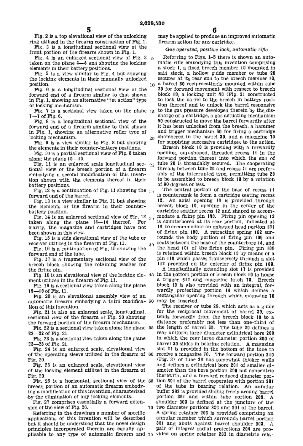
the frictional drag of the projectile on the barrel. hammer mechanism in its fired position and the
It is deemed obvious that this force is of a very ”6 barrel in battery position.
small magnitude once the engraving is accom-
plished, although it exists for the entire time that
the projectile is in the barrel.
3. A forward force on the barrel represented
by the forward component of the reaction force
produced between the helical-shaped lands and
the projectile. This force may be readily cal-
culated for any particular cartridge and barrel
knowing the muzzle velocity of the projectile, the
barrel time of the projectile and the twist of the
rifling.
4. A rearward force on the barrel produced by
the reaction of the gases issuing from the muzzle
upon the barrel.
When a so-called bottle-neck cartridge case is
utilized, which is the construction commonly
found in high-powered cartridges, such, for ex-
ample, as the U. S. Army cal. .30, M1906, then an
additional component of force is produced on the
barrel. This force is produced by the action of
the gas pressure within the barrel upon the re-
sultant rearwardly facing area of the cartridge
case. This area generally comprises the differ-
ence in interior area of the base of the cartridge
and the maximum cross-sectional area of the
projectile.
Adding all of the described forward forces to-
gether, the result for any commonly known car-
tridge and barrel is a resultant forward force on
the barrel which is 25 to 75 percent less than the
rearward force exerted by the same cartridge
upon the breech member.
It has already been mentioned that a firearm
action built around a forwardly movable barrel
results in a simplified design and hence an ap-
preciable saving in weight of the complete fire-
arm. In accordance with this invention a much
greater percentage of the mass of the gun may
be incorporated on the barrel. This will be
recognized to those skilled in the art as a most
desirable condition inasmuch as the mass of the
barrel is really the most essential mass of the
gun. The heavier the barrel, obviously the
greater is its ability to absorb heat produced by
firing. However, in the application of this inven-
tion, the increase in mass of the barrel has the
additional advantage of decreasing the size of
the locking element. The barrel mass, in a sense,
constitutes the “blow-back” mass of the gun.
Thus for any medium-powered cartridge, for ex-
ample, the U. S. carbine cal. .30, Ml, an action
constructed in accordance with this invention,
utilizing a forwardly movable barrel with as
much mass built into the barrel as consistent
55 with the overall weight requirements of the
weapon, requires no locking system at all, or at
the most, merely a non-positive, delay lock. The
reduction in the force operating to separate the
barrel from the breech, coupled with the large
mass of the barrel resisting acceleration of the
barrel by such forces, insures that the barrel will
not move substantially away from the breech
until the pressure within the barrel has dropped
65 to a safe value.
The specific nature of the invention as well as
other objects and advantages thereof will clearly
appear from a description of a preferred embodi-
ment as shown in the accompanying drawings
70 in which:
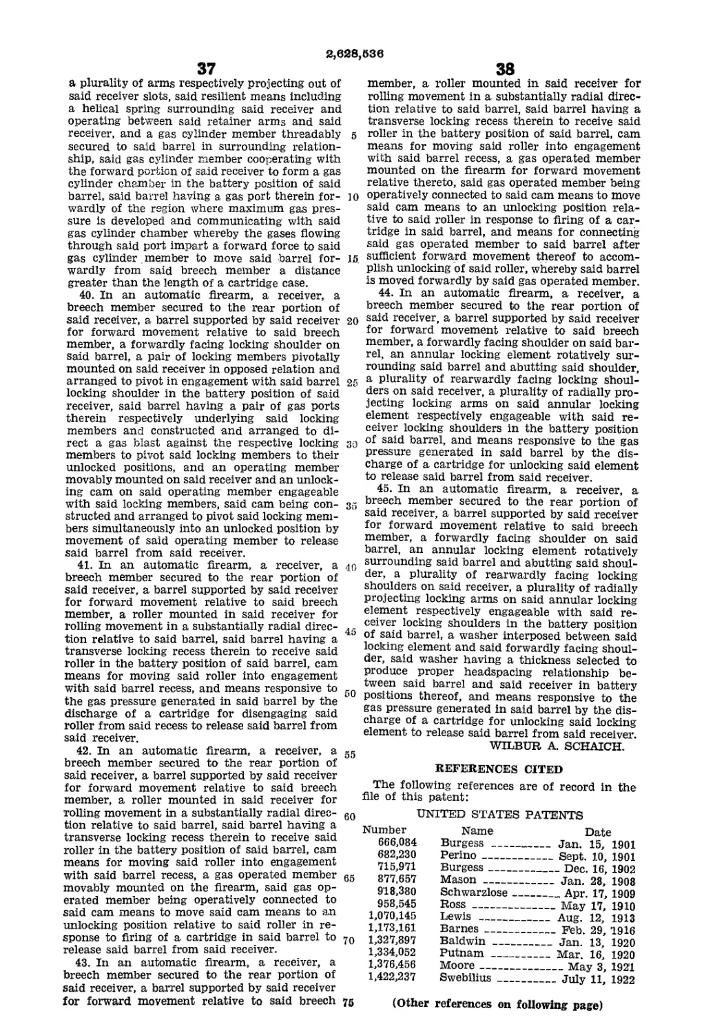
Fig. 1 is a longitudinal sectional view of the
rear portion of an automatic firearm embodying
this invention. The firearm is shown with the
2,в28,53в
5
Fig. 2 is a top eleVational view of the unlocking
ring utilized in the firearm construction of Fig. 1.
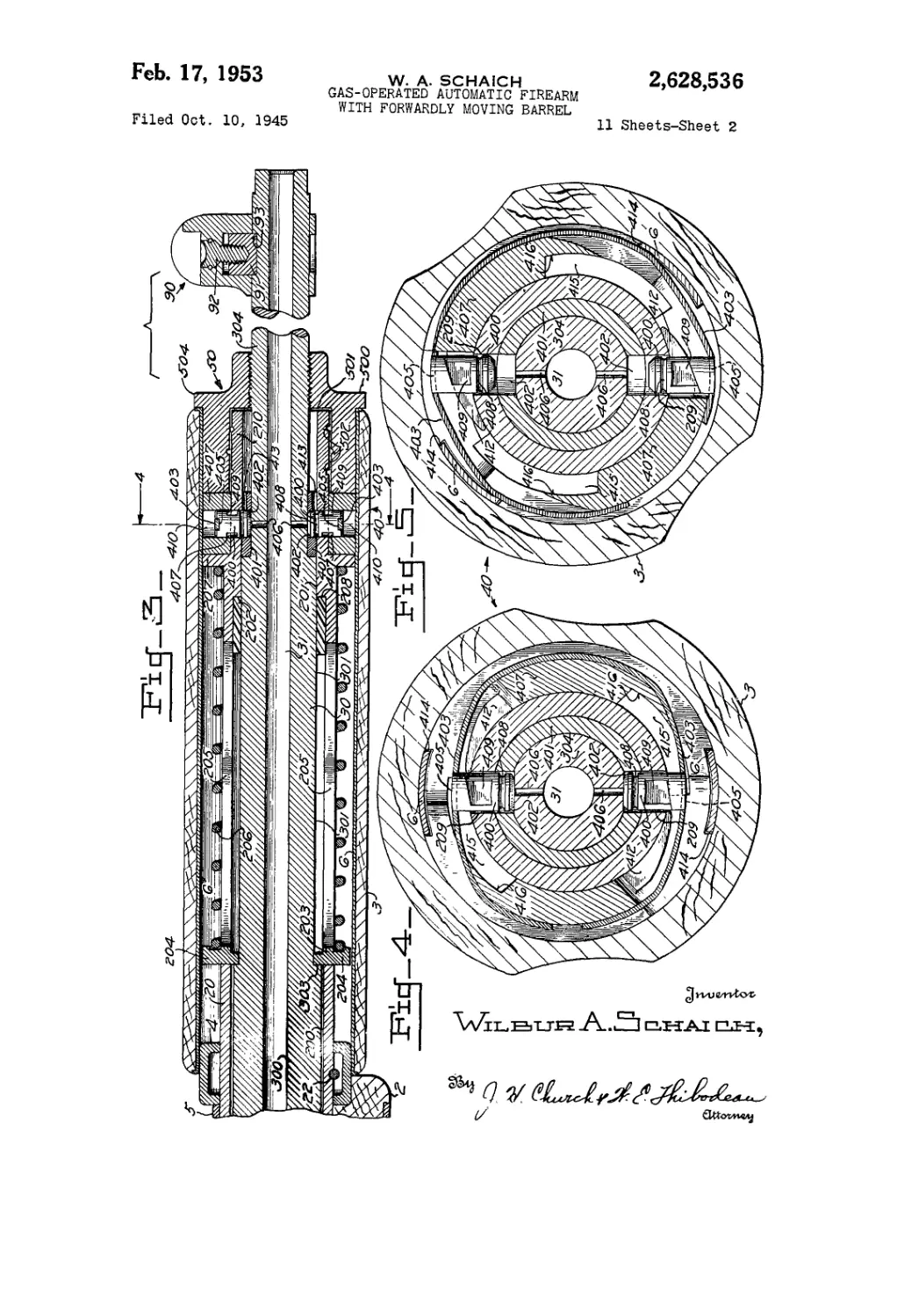
Fig. 3 is a longitudinal sectional view of the
front portion of the firearm shown in Fig. 1.
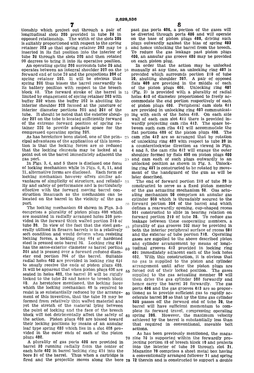
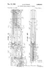
Fig. 4 is an enlarged sectional view of Fig. 3
taken on the plane 4—4 and showing the locking
elements in their battery positions.
Fig. 5 is a view similar to Fig. 4 but showing
the locking elements in their manually unlocked
position.
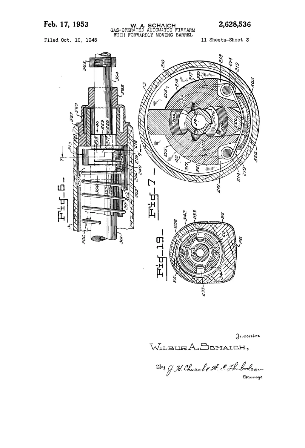
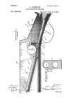
Fig. 6 is a longitudinal sectional view of the
forward end of a firearm similar to that shown
in Fig. 1, showing an alternative “jet action” type
of locking mechanism.
Fig. 7 is a sectional view taken on the plane
1—1 of Fig. 6.
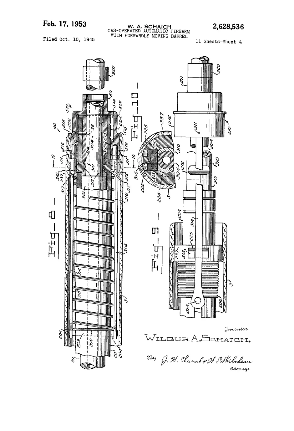
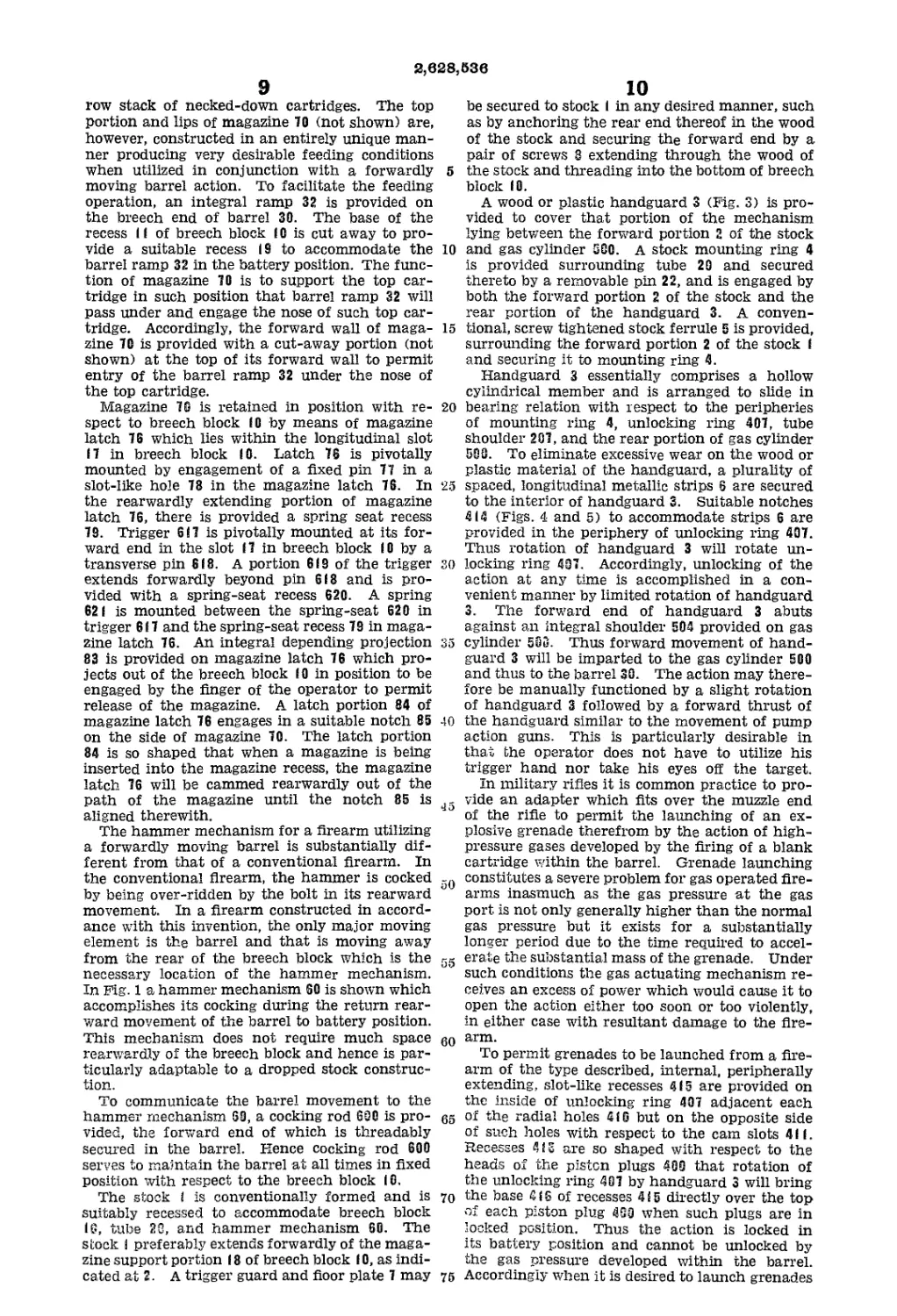
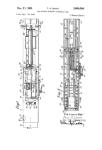
Fig. 8 is a longitudinal sectional view of the
forward end of a firearm similar to that shown
in Fig. 1, showing an alternative roller type of
locking mechanism.
Fig. 9 is a view similar to Fig. 8 but showing
the elements in their counter-battery positions.
Fig. 10 is a partial sectional view of Fig. 8 taken
along the plane 10—10.
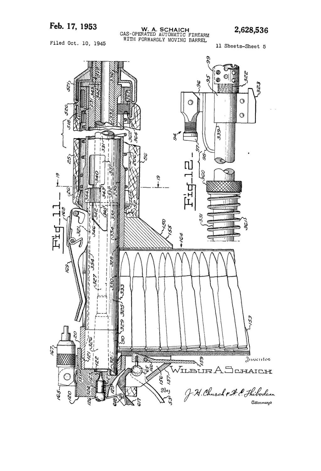
Fig. 11 is an enlarged scale longitudinal sec-
tional view of the breech portion of a firearm
embodying a second modification of this inven-
tion shown with the elements thereof in their
battery positions.
Fig. 12 is a continuation of Fig. 11 showing the
forward end of the barrel.
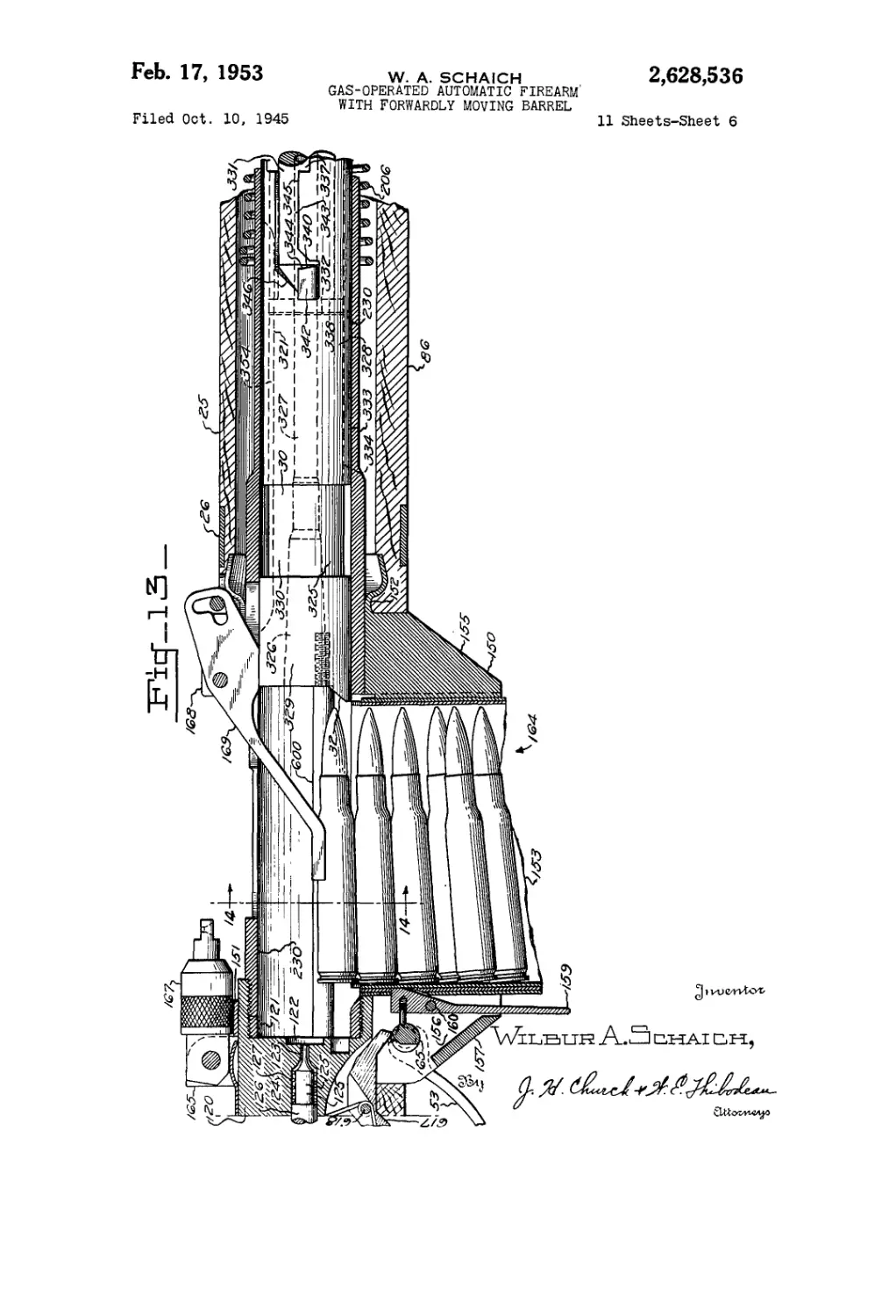
Fig. 13 is a view similar to Fig. 11 but showing
the elements of the firearm in their counter-
battery position.
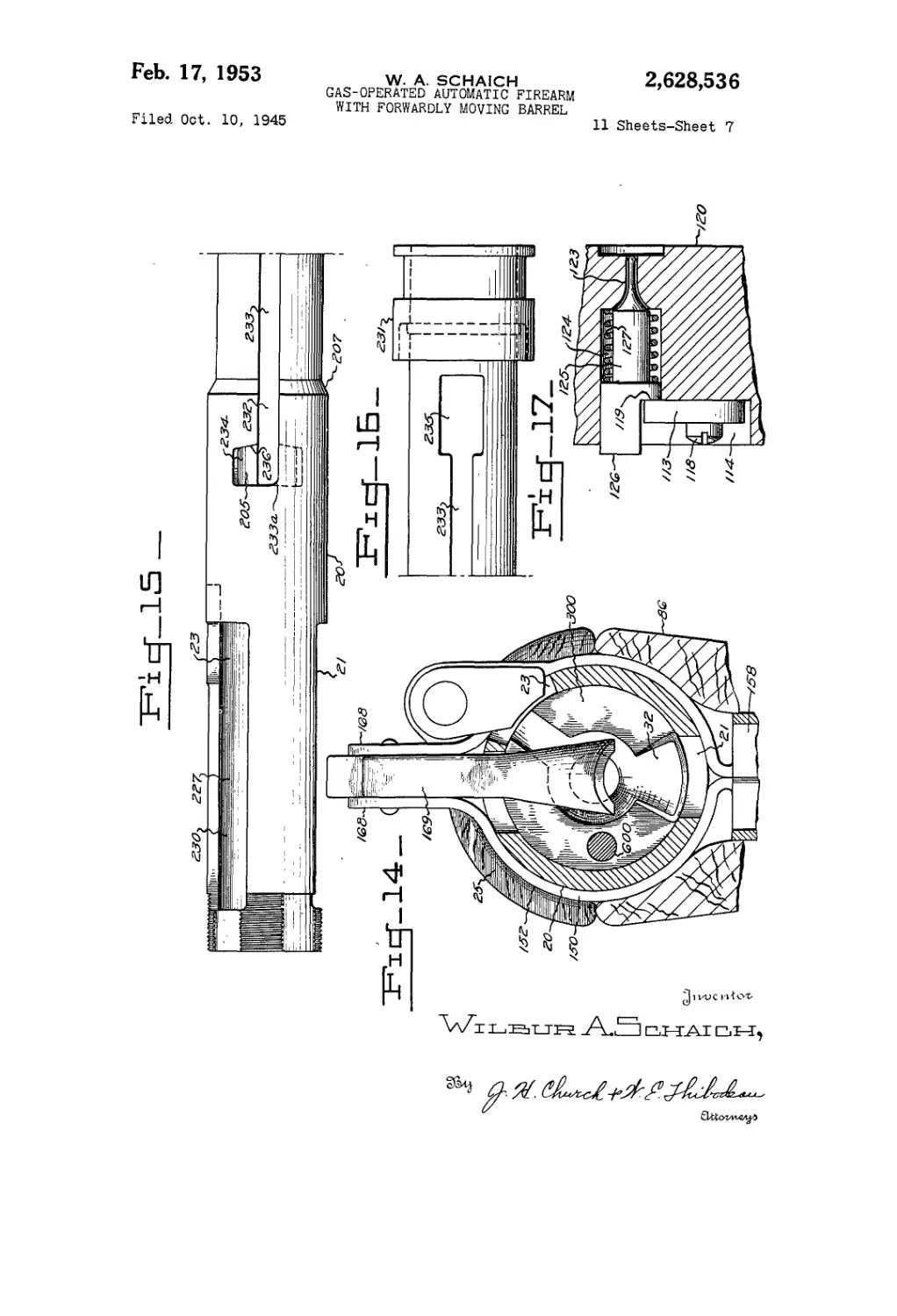
Fig. 14 is an enlarged sectional view of Fig. 13
taken along the plane 14—14 thereof. For
clarity, the magazine and cartridges have not
been shown in this view.
Fig. 15 is a side elevational view of the tube or
receiver utilized in the firearm of Fig. 11.
Fig. 16 is a continuation of Fig. 15 showing the
forward end of the tube.
Fig. 17 is a fragmentary sectional view of the
breech block showing the retaining washer for
the firing pin.
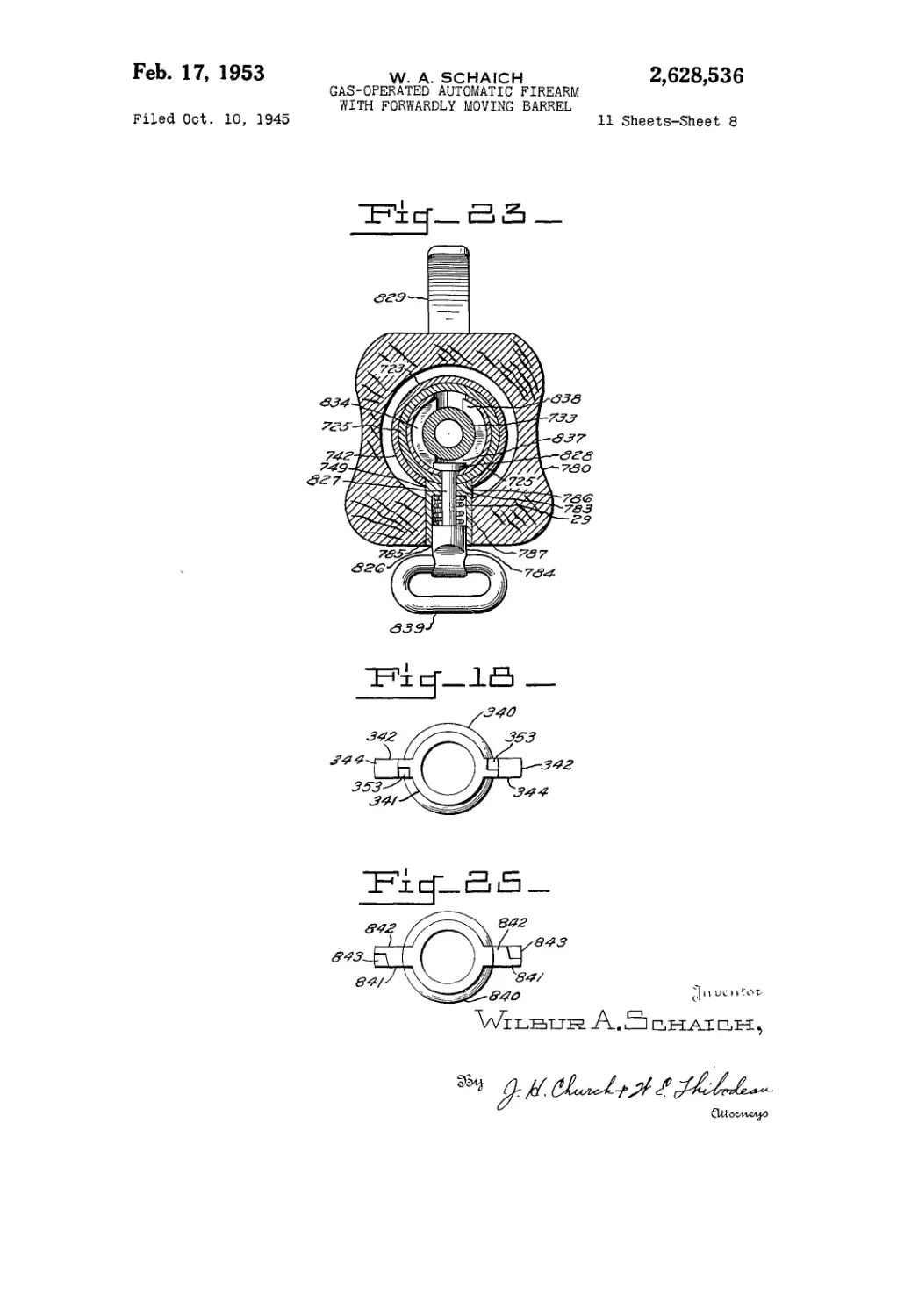
Fig. 18 is an elevational view of the locking ele-
ment utilized in the firearm of Fig. 11.
Fig. 19 is a sectional view taken along the plane
I9—19 of Fig. 11.
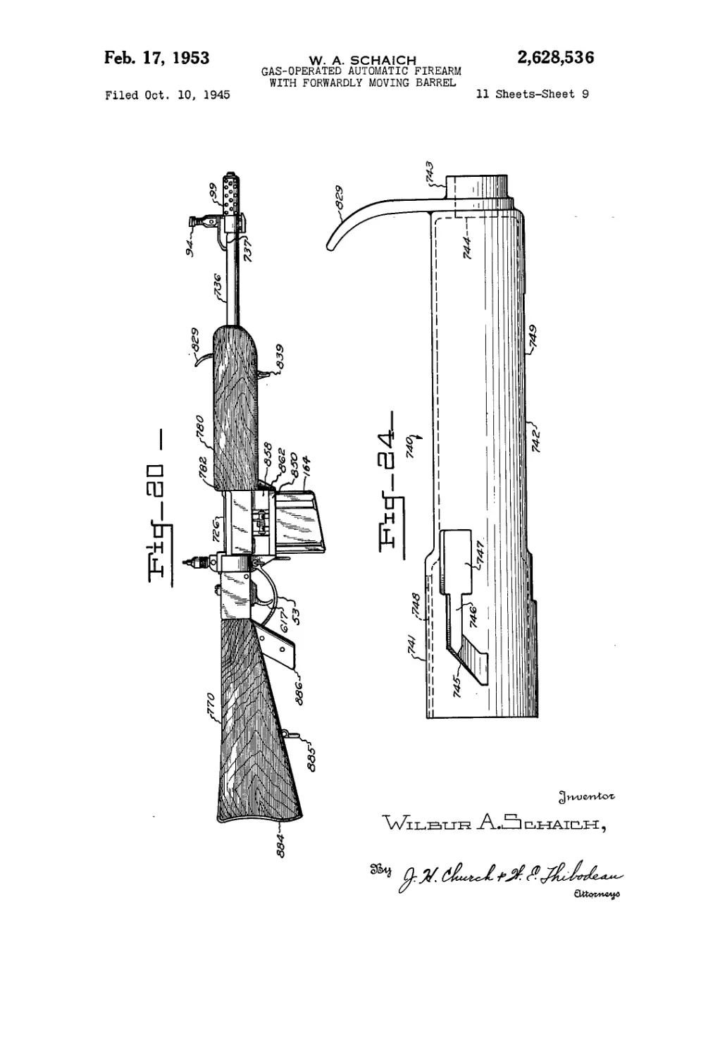
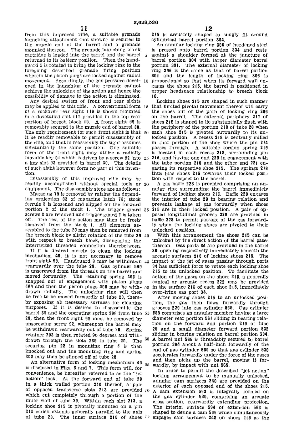
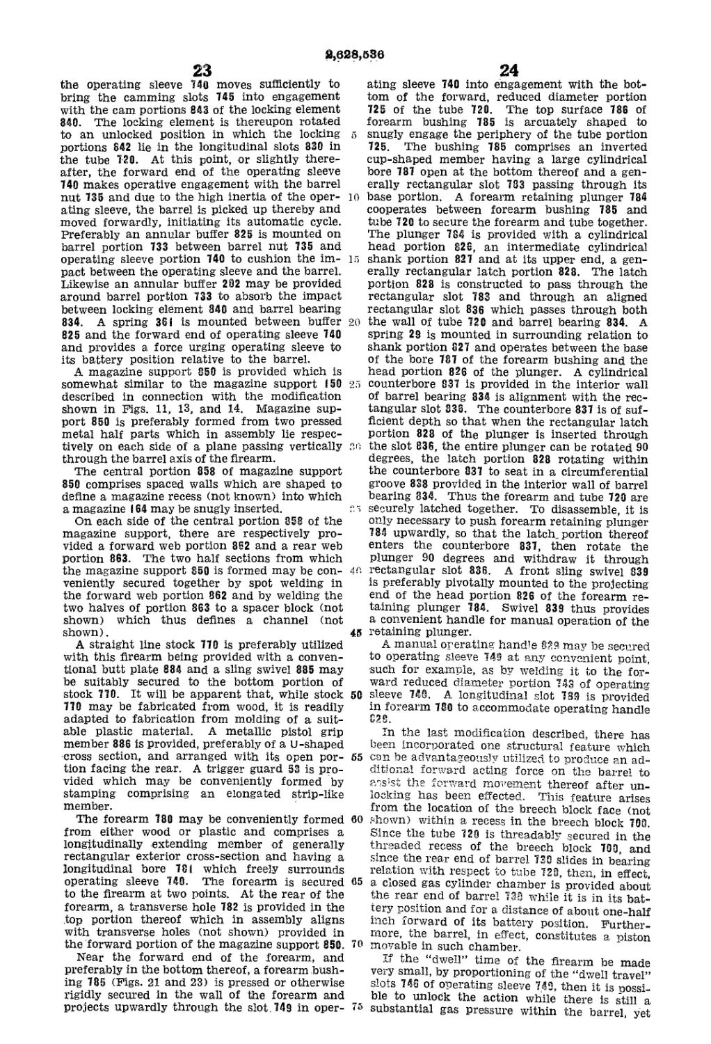
Fig. 20 is an elevational assembly view of an
automatic firearm embodying a third modifica-
tion of this invention.
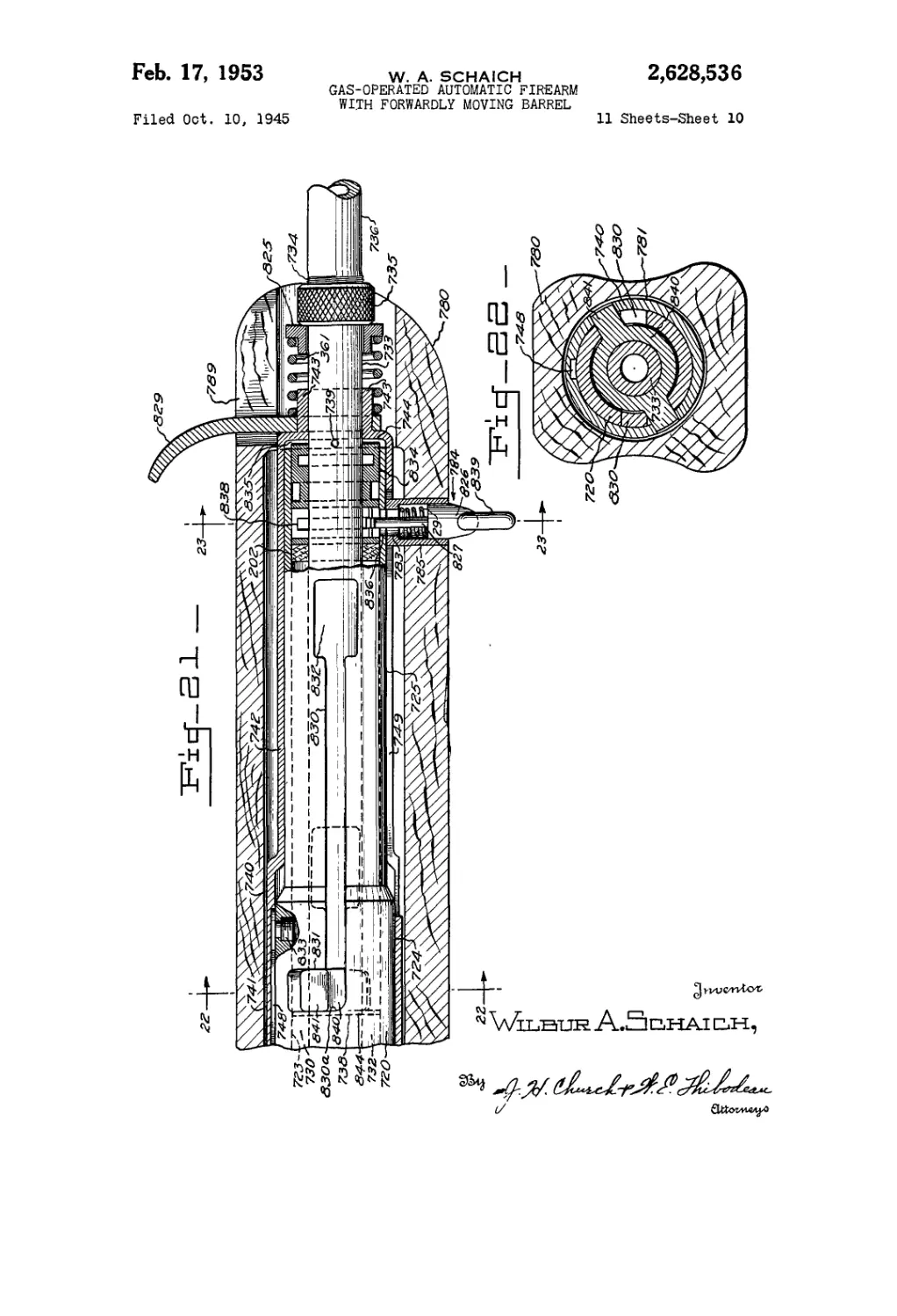
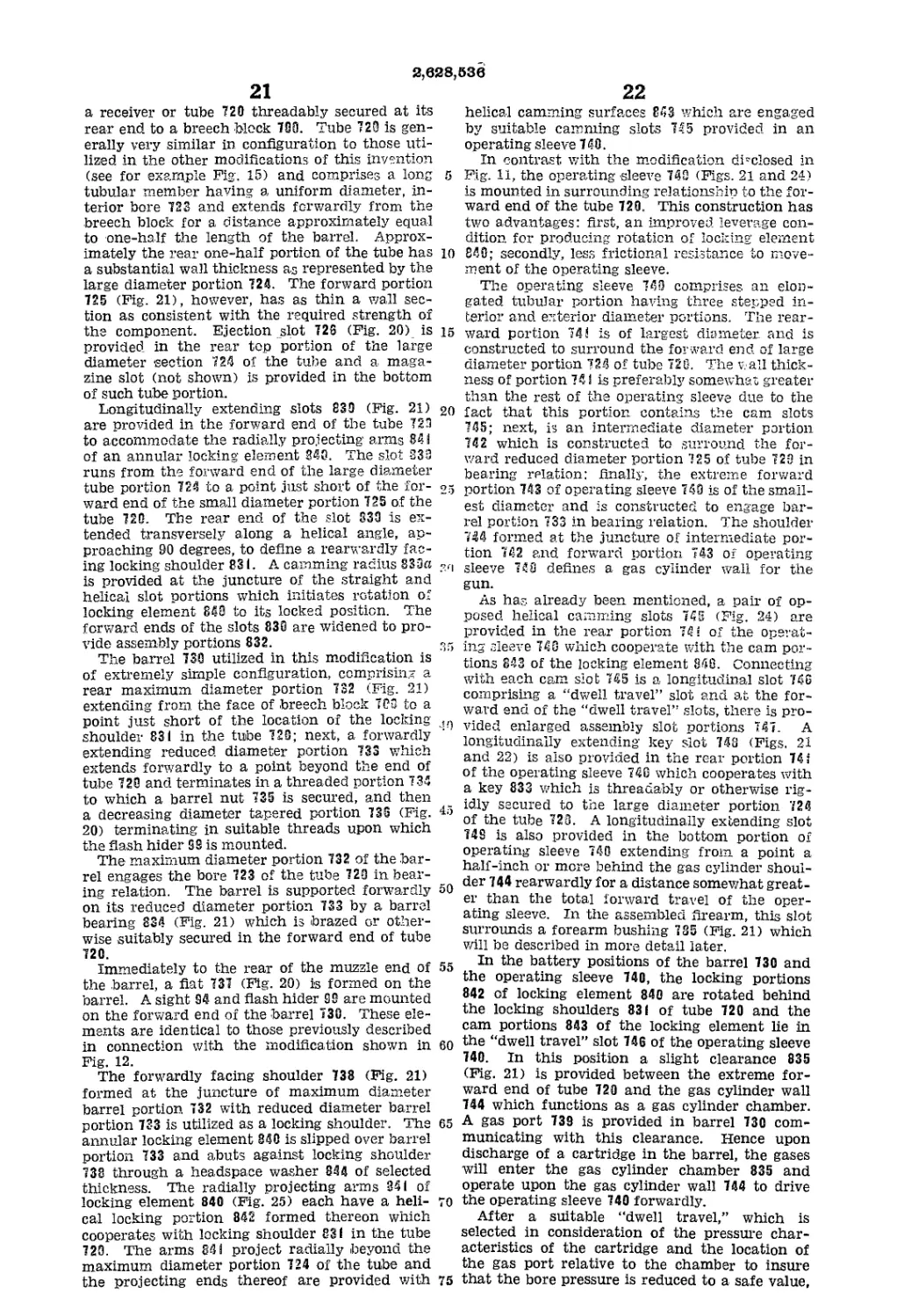
Fig. 21 is also an enlarged scale, longitudinal,
sectional view of the firearm of Fig. 20 showing
the forward portion of the firearm mechanism.
Fig. 22 is a sectional view taken along the plane
22—22 of Fig. 21.
Fig. 23 is a sectional view taken along the plane
23—23 of Fig. 21.
Fig. 24 is an enlarged scale, elevational view
of the operating sleeve utilized in the firearm of
Fig. 20.
Fig. 25 is an enlarged scale, elevational view
of the locking element utilized in the firearm of
Fig. 20.
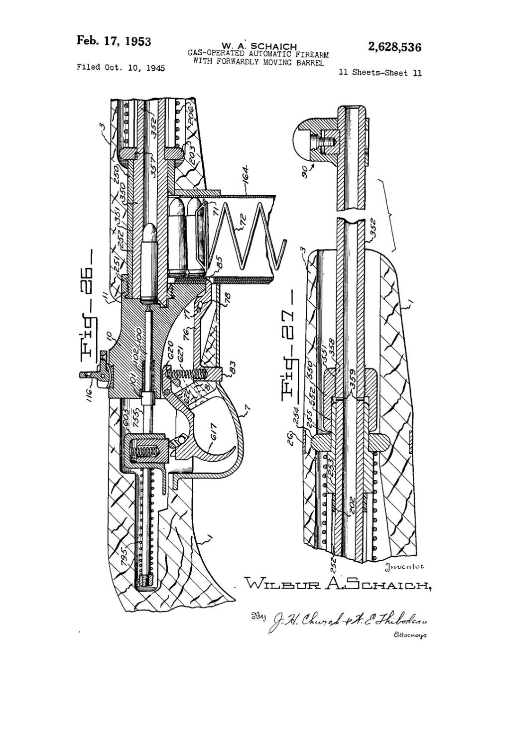
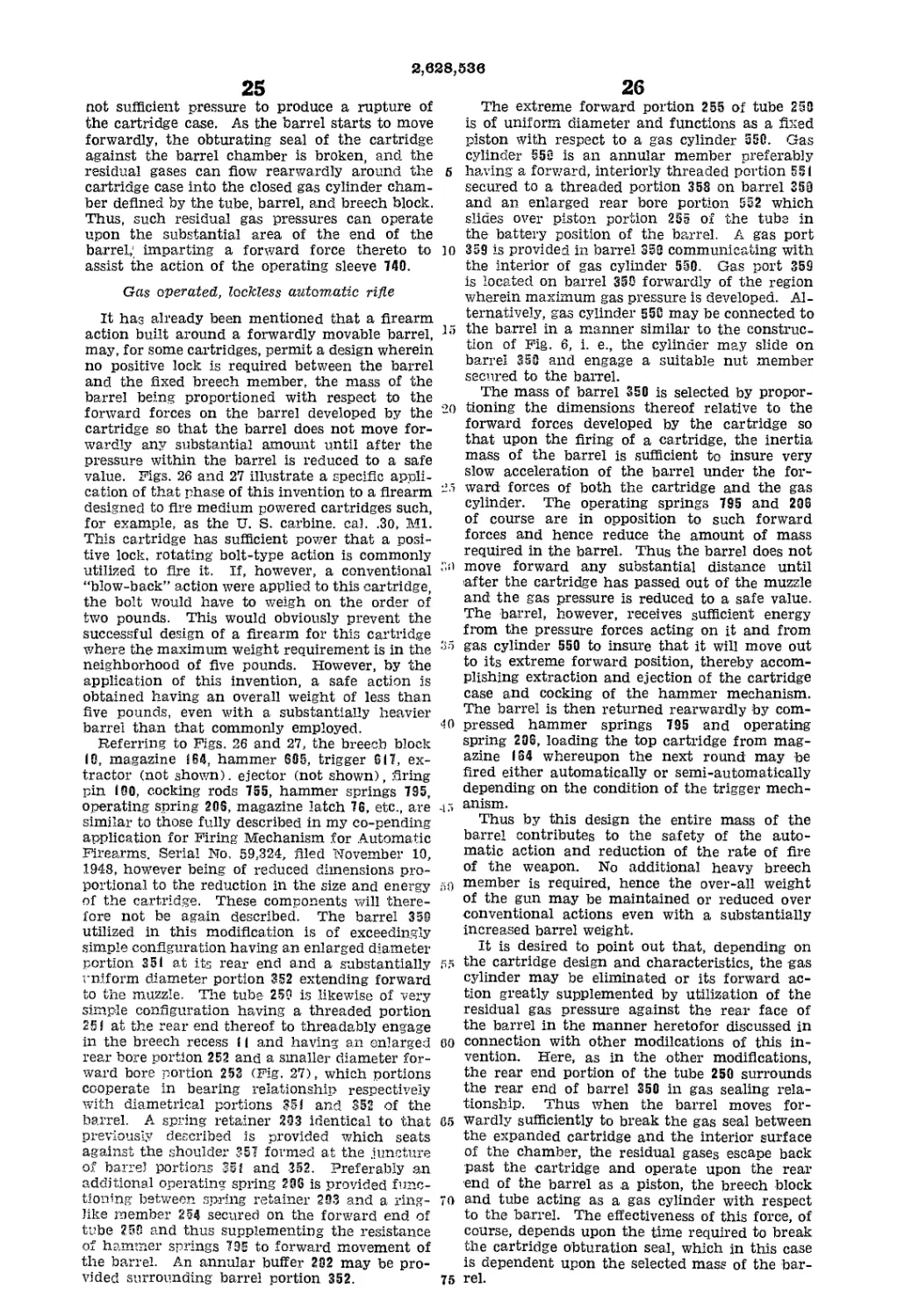
Fig. 26 is a horizontal, sectional view of the
breech portion of an automatic firearm embody-
ing a modification of this invention, characterized
by the elimination of any locking elements.
Fig. 27 comprises essentially a forward exten-
sion of the view of Fig. 26.
Referring to the drawings a number of specific
applications of this invention will be described
but it should be understood that the novel design
principles incorporated therein are equally ap-
plicable to any type of automatic firearm and
6
may be applied to produce an improved automatic
firearm action for any cartridge.
Gas operated, positive lock, automatic rifle
Referring to Figs. 1-5 there is shown an auto-
matic rifle embodying this invention comprising
a stock I, a fixed breech member 10 mounted in
said stock, a hollow guide member or tube 20
secured at its rear end to the breech member 10,
a barrel 30 reciprocatingly mounted within tube
20 for forward movement with respect to breech
block 10, a locking unit 40 (Fig. 3) constructed
to lock the barrel to the breech in battery posi-
tion thereof and to unlock the barrel responsive
to the gas pressure developed therein by the_ dis-
charge of a cartridge, a gas actuating mechanism
50 constructed to move the barrel forwardly after
it has been unlocked from the breech, a hammer
and trigger mechanism 60 for firing a cartridge
chambered in the barrel 30, and a magazine 70
for supplying successive cartridges to the action.
Breech block to is provided with a forwardly
opening, cup-shaped, threaded recess I f in the
forward portion thereof into which the end of
tube 20 is threadably secured. The cooperating
threads between tube 20 and recess i I are prefer-
ably of the interrupted type, permitting tube 20
to be assembled to breech block 10 by a rotation
of 90 degrees or less.
The central portion of the base of recess 11
is countersunk to form a cartridge seating recess
12. An axial opening (3 is provided through
breech block IB, opening in the center of the
cartridge seating recess 12 and shaped to accom-
modate a firing pin 190. Firing pin opening 13
is counterbored at its rear portion, indicated at
14, to accommodate an enlarged head portion Ш
of firing pin 190. A retracting spring 192 sur-
rounds the body portion of firing pin 100 and
seats between the base of the counterbore 14, and
the head 101 of the firing pin. Firing pin 100
is retained within breech block 10 by means of a
pin 110 which passes transversely through a slot
112 provided on the exterior of firing pin 100.
A longitudinally extending slot 17 is provided
in the bottom portion of breech block 10 to house
a trigger 617 and magazine latch 76. Breech
block IB is also provided with an integral, for-
wardly projecting portion 18 which defines a
rectangular opening through which magazine 70
may be inserted.
The receiver or tube 28, which acts as a guide
for the reciprocal movement of barrel 30, ex-
tends forwardly from the breech block 10 to a
distance preferably not less than one-third of
the length of barrel 39. The tube 20 defines a
rear uniform large diameter cylindrical bore 200
in which the rear large diameter portion 300 of
barrel 30 slides in bearing relation. A magazine
slot 21 is provided in the bottom of the tube to
receive a magazine 70. The forward portion 210
(Fig. 3) of tube 20 has somewhat thicker walls
and defines a cylindrical bore 291 of smaller di-
ameter than the bore portion 200 but concentric
therewith, and a forward reduced diameter por-
tion 301 of the barrel cooperates with portion 201
of the tube in bearing relation. An annular
buffer 202 is provided sliding freely around barrel
portion 301 and within tube portion 200. A
shoulder 303 is defined at the juncture of the
two diameter portions 300 and 391 of the barrel.
A spring retainer 293 is provided comprising an
annular member which surrounds barrel portion
391 and abuts against barrel shoulder 303. A
pair of integral radial projections 204 are pro-
vided on spring retainer 203 in diametric rela-
5
10
15
20
10
45
50
55
60
65
70
75
2,628,636
7
tionship which project out through a pair of
longitudinal slots 205 provided in tube 20 in
opposed relationship. The width of the slots 205
is suitably proportioned with respect to the spring
retainer 203 so that spring retainer 203 may be
inserted in its fiat position into the interior of
tube 20 through the slots 205 and then rotated
90 degrees to bring it into its operative position.
An operating spring 20S surrounds tube 29 and
operates between an integral shoulder 207 on the
forward end of tube 20 and the projections 204 of
spring retainer 203. It will be obvious that
spring 205 thus biases the barrel rearwardly to
its battery position with respect to the breech
block IG. The forward stroke of the barrel is
limited by engagement of spring retainer 203 with
buffer 292 when the buffer 2S2 is abutting the
interior shoulder 208 formed at the juncture of
interior diameter portions 290 and 201 of the
tube. It should be noted that the exterior shoul-
der 207 on the tube is located sufficiently forward
of the extreme forward position of spring re-
tainer 233 to provide adequate space for the
compressed operating spring 28S.
As has heretofore been stated, one of the prin-
cipal advantages of the application of this inven-
tion is that the locking forces are so reduced
that the locking elements may be locked at a
point out on the barrel immediately adjacent the
gas port.
In Figs. 3, 4, and 5 there is disclosed one form
of locking mechanism while in Figs. 6, 8, 11, and
21, alternative forms are disclosed. Each form of
locking mechanism however offers similar ad-
vantages of simplicity of structure, and reliabil-
ity and safety of performance and is particularly
effective with the forward moving barrel con-
struction inasmuch as the mechanism can be
located on the barrel in the vicinity of the gas
port.
The locking mechanism S8 shown in Figs. 3-5
comprises a plurality of piston plugs 400 which
are mounted in radially arranged holes 209 pro-
vided in the forward thick walled portion 219 of
tube 20. In view of the fact that the steel gen-
erally utilized in firearm barrels is in a relatively
soft condition and would deform when resisting
locking forces, a locking ring 4-0| of hardened
steel is pressed onto barrel 88. Locking ring 491
has the same-exterior diameter as barrel portion
301 and is pressed over a forward reduced diam-
eter end portion 394 of the barrel. Suitable
radial holes 402 are provided in locking ring 43 5
to snugly receive the ends of piston plugs 400.
It will be apparent that when piston plugs 490 are
seated in holes 402, the barrel 39 will be rigidly
locked to the tube 23 and hence to breech block
19. As heretofore mentioned, the locking force
which the locking mechanism 40 is required to
resist is so substantially reduced by the arrange-
ment of this invention, that the tube 29 may be
formed from relatively thin walled material and
yet the stretch of the material lying between
the point of locking and the face of the breech
block will not detrimentally affect the safety of
the action. Piston plugs 480 are biased toward
their locking positions by means of an annular
leaf type spring 493 which lies in a slot 405 pro-
vided in the outer ends of each of the piston
plugs 409.
A plurality of gas ports 40 S are provided in
barrel 30 running radially from the center of
each hole 402 in barrel locking ring 431 into the
bore 31 of the barrel. Thus when a cartridge is
fired and the projectile moves along the bore
8
past gas ports 406, a portion of the gases will
be diverted through ports 406 and will operate
on the base of piston plugs 400, driving such
plugs outwardly against the bias of spring 403
5 and hence unlocking the barrel from the breech.
To reduce the gas leakage past piston plugs
400, an annular gas groove 408 may be provided
on each piston plug.
In order that the action may be unlocked
io manually at any time, an unlocking ring 407 is
provided which surrounds portion 2Ё0 of tube
20, abutting shoulder 207. A pair of opposed
fiats 409 are provided in the middle of each
of the piston plugs 400. Unlocking ring 407
15 (Fig. 2) is provided with a plurality of radial
holes 410 of diameter proportioned to freely ac-
commodate the end portion respectively of each
of piston plugs 408. Peripheral cam slots 411
are provided in unlocking ring 407 communicat-
20 ing with each of the holes 410. On each side
wall of each cam slot 411 there is provided in-
wardly projecting cam ribs 412'. The space be-
tween such cam ribs 412 will accommodate the
flat portions 409 of the piston plugs 400. The
25 cam ribs 412 are so arranged that by rotation
of unlocking ring 407 with respect to tube 20 in
a counterclockwise direction as viewed in Figs.
4 and 5, the cam ribs 412 will engage the outer
shoulder formed by flats 409 on piston plugs 400
35 and cam each of such plugs outwardly to an
unlocked position as shown in Fig. 5. Unlock-
ing ring 407 is constructed to be rotated by move-
ment of the handguard of the gun as will be
later described.
35 The end of forward portion 210 of tube 20 is
constructed to serve as a fixed piston member
of the gas actuating mechanism 50. Gas actu-
ating mechanism 50 comprises an annular gas
cylinder 580 which is threadably secured to the
io forward portion 304 of the barrel and which
defines a rearwardly opening, cup-shaped recess
581 constructed to slide in bearing relation on
forward portion 2IB of tube 20. To reduce gas
leakage between these cooperating members, a
.15 plurality of gas grooves 502 may be provided in
both the interior peripheral surface of recess 501
and the exterior of tube portion 210. Operating
gases are supplied to the above described piston
and cylinder arrangement by means of longi-
60 tudinal grooves 413 provided in locking ring
401 immediately adjacent each of the lock holes
492. With this construction, it is obvious that
no gas is supplied to the piston and cylinder
arrangement until after the piston plugs are
55 forced out of their locked position. The gases
supplied to the gas actuating member 50 will
then drive the gas cylinder 50® forwardly and
hence carry the barrel 30 forwardly. The gas
ports 406 and the gas grooves 4(3 are so propor-
80 tioned as to provide sufficient gas to rapidly ac-
celerate barrel 30 so that by the time gas cylinder
500 passes off the forward end of tube 20, the
barrel will have sufficient momentum to com-
plete its forward travel, compressing operating
85 spring 206. However, the maximum velocity
achieved by the barrel is substantially less than
that required in conventional, movable bolt
actions.
As has been previously mentioned, the maga-
70 zine 70 is supported within the forwardly pro-
jecting portion 18 of breech block SO and projects
into the interior of tube 2'0 through slot 21.
Magazine 70 comprises a sheet metal box having
a conventionally arranged follower 71 and spring
76 72 therein and is constructed to support a double
2,628,636
9
row stack of necked-down cartridges. The top
portion and lips of magazine 70 (not shown) are,
however, constructed in an entirely unique man-
ner producing very desirable feeding conditions
when utilized in conjunction with a forwardly
moving barrel action. To facilitate the feeding
operation, an integral ramp 32 is provided on
the breech end of barrel 30. The base of the
recess 11 of breech block 10 is cut away to pro-
vide a suitable recess 19 to accommodate the
barrel ramp 32 in the battery position. The func-
tion of magazine 70 is to support the top car-
tridge in such position that barrel ramp 32 will
pass under and engage the nose of such top car-
tridge. Accordingly, the forward wall of maga-
zine 70 is provided with a cut-away portion (not
shown) at the top of its forward wall to permit
entry of the barrel ramp 32 under the nose of
the top cartridge.
Magazine 70 is retained in position with re-
spect to breech block 10 by means of magazine
latch 7 В which lies within the longitudinal slot
17 in breech block 10. Latch 76 is pivotally
mounted by engagement of a fixed pin 77 in a
slot-like hole 78 in the magazine latch 76. In
the rearwardly extending portion of magazine
latch 76, there is provided a spring seat recess
79. Trigger 6!7 is pivotally mounted at its for-
ward end in the slot 17 in breech block 10 by a
transverse pin 618. A portion 619 of the trigger
extends forwardly beyond pin 618 and is pro-
vided with a spring-seat recess 620. A spring
621 is mounted between the spring-seat 620 in
trigger 617 and the spring-seat recess 79 in maga-
zine latch 76. An integral depending projection
83 is provided on magazine latch 76 which pro-
jects out of the breech block 10 in position to be
engaged by the finger of the operator to permit
release of the magazine. A latch portion 84 of
magazine latch 76 engages in a suitable notch 85
on the side of magazine 70. The latch portion
84 is so shaped that when a magazine is being
inserted into the magazine recess, the magazine
latch 76 will be cammed rearwardly out of the
path of the magazine until the notch 85 is
aligned therewith.
The hammer mechanism for a firearm utilizing
a forwardly moving barrel is substantially dif-
ferent from that of a conventional firearm. In
the conventional firearm, the hammer is cocked
by being over-ridden by the bolt in its rearward
movement. In a firearm constructed in accord-
ance with this invention, the only major moving
element is the barrel and that is moving away
from the rear of the breech block which is the
necessary location of the hammer mechanism.
In Fig. 1 a hammer mechanism 60 is shown which
accomplishes its cocking during the return rear-
ward movement of the barrel to battery position.
This mechanism does not require much space
rearwardly of the breech block and hence is par-
ticularly adaptable to a dropped stock construc-
tion.
To communicate the barrel movement to the
hammer mechanism GO, a cocking rod 600 is pro-
vided, the forward end of which is threadably
secured in the barrel. Hence cocking rod 600
serves to maintain the barrel at all times in fixed
position with respect to the breech block 16,
The stock i is conventionally formed and is
suitably recessed to accommodate breech block
16, tube 20, and hammer mechanism 60. The
stock I preferably extends forwardly of the maga-
zine support portion 18 of breech block 10, as indi-
cated at 2. A trigger guard and floor plate 7 may
5
10
15
20
25
30
35
to
45
50
55
60
65
70
75
10
be secured to stock I in any desired manner, such
as by anchoring the rear end thereof in the wood
of the stock and securing the forward end by a
pair of screws 8 extending through the wood of
the stock and threading into the bottom of breech
block IS.
A wood or plastic handguard 3 (Fig. 3) is pro-
vided to cover that portion of the mechanism
lying between the forward portion 2 of the stock
and gas cylinder S0O. A stock mounting ring 4
is provided surrounding tube 20 and secured
thereto by a removable pin 22, and is engaged by
both the forward portion 2 of the stock and the
rear portion of the handguard 3. A conven-
tional, screw tightened stock ferrule 5 is provided,
surrounding the forward portion 2 of the stock I
and securing it to mounting ring 4.
Handguard 3 essentially comprises a hollow
cylindrical member and is arranged to slide in
bearing relation with respect to the peripheries
of mounting ring 4, unlocking ring 407, tube
shoulder 287, and the rear portion of gas cylinder
500. To eliminate excessive wear on the wood or
plastic material of the handguard, a plurality of
spaced, longitudinal metallic strips 6 are secured
to the interior of handguard 3. Suitable notches
414 (Figs. 4 and 5) to accommodate strips 6 are
provided in the periphery of unlocking ring 407.
Thus rotation of handguard 3 will rotate un-
locking ring 407. Accordingly, unlocking of the
action at any time is accomplished in a con-
venient manner by limited rotation of handguard
3. The forward end of handguard 3 abuts
against an integral shoulder 504 provided on gas
cylinder 58S. Thus forward movement of hand-
guard 3 will be imparted to the gas cylinder 500
and thus to the barrel 30. The action may there-
fore be manually functioned by a slight rotation
of handguard 3 followed by a forward thrust of
the handguard similar to the movement of pump
action guns. This is particularly desirable in
that the operator does not have to utilize his
trigger hand nor take his eyes ой the target.
In military rifles it is common practice to pro-
vide an adapter which fits over the muzzle end
of the rifle to permit the launching of an ex-
plosive grenade therefrom by the action of high-
pressure gases developed by the firing of a blank
cartridge within the barrel. Grenade launching
constitutes a severe problem for gas operated fire-
arms inasmuch as the gas pressure at the gas
port, is not only generally higher than the normal
gas pressure but it exists for a substantially
longer period due to the time required to accel-
erate the substantial mass of the grenade. Under
such conditions the gas actuating mechanism re-
ceives an excess of power which would cause it to
open the action either too soon or too violently,
in either case with resultant damage to the fire-
arm.
To permit grenades to be launched from a fire-
arm of the type described, internal, peripherally
extending, slot-like recesses 415 are provided on
the inside of unlocking ring 497 adjacent each
of the radial holes 416 but on the opposite side
of such holes with respect to the cam slots 411.
Recesses 4!B are so shaped with respect to the
heads of the piston plugs 480 that rotation of
the unlocking ring 487 by handguard 3 will bring
the base 416 of recesses 48 5 directly over the top
of each piston plug 4S9 when such plugs are in
locked position. Thus the action is locked in
its battery position and cannot be unlocked by
the gas pressure developed within the barrel.
Accordingly when it is desired to launch grenades
2,628,636
11
from this improved rifle, a suitable grenade
launching attachment (not shown) is secured to
the muzzle end of the barrel and a grenade
mounted thereon. The grenade launching blank
cartridge is loaded into the barrel and the barrel
returned to its battery position. Then the hand-
guard 3 is rotated to bring the locking ring to the
foregoing described grenade firing position
wherein the piston plugs are locked against radial
movement. Accordingly, the gas pressure devel-
oped in the launching of the grenade cannot
achieve the unlocking of the action and hence the
possibility of damage to the action is eliminated.
Any desired system of front and rear sights
may be applied to this rifle. A conventional form
of a rockover rear sight 116 is shown mounted
in a dovetailed slot 117 provided in the top rear
portion of breech block 10. A front sight 90 is
removably secured to the muzzle end of barrel 30.
The only requirement for such front sight is that
it be readily removable to permit disassembly of
the rifle, and that in reassembly the sight assumes
substantially the same position. One suitable
form of the front sight may utilize a radially
movable key 91 which is driven by a screw 82 into
a key slot 93 provided in barrel 30. The details
of such sight however form no part of this inven-
tion.
Disassembly of this improved rifle may be
readily accomplished without special tools or
equipment. The disassembly steps are as follows:
Magazine 70 is removed by raising the depend-
ing projection S3 of magazine latch 76; stock
ferrule 5 is loosened and slipped off the forward
portion 2 of the stock I. The trigger guard
screws 8 are removed and trigger guard 7 is taken
off. The rest of the action may then be freely
removed from the stock t. All elements as-
sembled to the tube 20 may then be removed from
the breech block by slight rotation of the tube 20
with respect to breech block, disengaging the
interrupted threaded connection therebetween.
If it is desired merely to clean the locking
mechanism 40, it is not necessary to remove
front sight 90. Handguard 3 may be withdrawn
rearwardly over the tube 29. Gas cylinder 500
is unscrewed from the threads on the barrel and
moved forwardly. The retaining spring 403 is
snapped out of engagement with piston plugs
400 and then the piston plugs 400 may be with-
drawn radially. The unlocking ring will then
be free to be moved forwardly of tube 20, there-
by exposing all necessary surfaces for cleaning
purposes. If it is desired to disassemble the
barrel 30 and the operating spring 206 from tube
20, then the front sight 90 must be removed by
unscrewing screw 92, whereupon the barrel may
be withdrawn rearwardly out of tube 20. Spring
retainer 203 is then rotated 90 degrees and with-
drawn through the slots 205 in tube 20. The
securing pin 22 in mounting ring 4 is then
knocked out and the mounting ring and spring
206 may then be slipped off of tube 20.
An alternative form of locking mechanism 40
is disclosed in Figs. 6 and 7. This form will, for
convenience, be hereafter referred to as the “jet
action” lock. At the forward end of tube 20
in a thick walled portion 2! 0 thereof, a pair
of opposed transverse slots 213 are provided
which cut completely through a portion of the
inner wall of tube 20. Within each slot 213. a
locking shoe 215 is pivotally mounted on a pin
2 !4 which extends generally parallel to the axis
of tube 20. The inner surface 216 of shoes
a
10
15
20
25
30
35
40
45
50
55
60
65
70
75
12
215 is arcuately shaped to snugly fit around
cylindrical barrel portion 304.
An annular locking ring 396 of hardened steel
is pressed onto barrel portion 304 and rests
against a shoulder formed at the juncture of
barrel portion 304 with larger diameter barrel
portion 301. The external diameter of locking
ring 306 is the same as that of barrel portion
301 and the length of locking ring 306 is
proportioned so that when its forward wall en-
gages the shoes 215, the barrel is positioned in
proper headspace relationship to breech block
10.
Locking shoes 215 are shaped in such manner
that limited pivotal movement thereof will carry
the shoes out of the path of locking ring 306
on the barrel. The external periphery 217 of
shoes 215 is shaped to lie substantially flush with
the periphery of the portion 210 of tube 20 when
each shoe 215 is pivoted outwardly to its un-
locked position. A recess 218 is centrally milled
in that portion of the shoe where the pin 214
passes through. A suitable torsion spring 219
is located in each recess 213, surrounding pin
214, and having one end 220 in engagement with
the tube portion 210 and the other end 221 en-
gaging its respective shoe 215. The springs '2(9
thus bias shoes 2(5 towards their locked posi-
tion with respect to the barrel.
A gas baffle 228 is provided comprising an an-
nular ring surrounding the barrel immediately
forward of locking shoes 2(5. Baffle 228 engages
the interior of tube 20 in bearing relation and
prevents leakage of gas forwardly when shoes
2(5 are in their locked position. A pair of op-
posed longitudinal grooves 229 are provided in
baffle 228 to permit passage of the gas forward-
ly when the locking shoes are pivoted to their
unlocked position.
With this arrangement the shoes 2(5 can be
unlocked by the direct action of the barrel gases
thereon. Gas ports 34 are provided in the barrel
30, opening respectively immediately beneath the
arcuate surfaces 2(6 of locking shoes 2(5. The
impact of the jet of gases passing through ports
34 has sufficient force to rotate each locking shoe
2(5 to its unlocked position. To facilitate the
action of the gases on the shoes 2(5, a generally
conical or arcuate recess 222 may be provided
in the surface 2(6 of each shoe 2(5, immediately
over-lying gas port 34.
After moving shoes 2(5 to an unlocked posi-
tion, the gas then flows forwardly through
grooves 229 into gas cylinder 560. Gas cylinder
560 comprises an annular member having a large
diameter rear portion 56 ( sliding in bearing rela-
tion on the forward end portion 2(9 of tube
26 and a small diameter forward portion 562
sliding in bearing relation on barrel portion 364.
A barrel nut 565 is threadably secured to barrel
portion 304 about a half-inch forwardly of the
end of gas cylinder 566 so that gas cylinder 560
accelerates forwardly under the force of the gases
and then picks up the barrel, moving it for-
wardly, by impact with nut 565.
In order to permit the described “jet action”
locking arrangement to be manually unlocked,
annular cam surfaces 240 are provided on the
exterior of each opposed end of the shoes 2(5.
A cam extension 563 is integrally formed on
the gas cylinder 560, comprising an arcuate
cross-section, rearwardly extending projection.
The interior surface 564 of extension 563 is
shaped to define a cam 566 which simultaneously
engages cam surfaces 240 on shoes 2(5 as the
2,628,636
13
gas cylinder moves forward. The gas cylinder
560 is moved forward manually by the hand-
guard or forearm 3 which comprises a hollow
generally cylindrical member mounted in sur-
rounding relation to the forward end of tube 20 a
and abutting a shoulder 567 on the periphery
of gas cylinder 560. Thus as gas cylinder 560
is manually moved forward, the locking shoes
215 are cammed out of locking position by cam
extension 563. At the completion of the cammed lo
movement of shoes 215, gas cylinder 560 moves
into engagement with barrel nut 565 and further
forward movement of the gas cylinder moves the
barrel forwardly to open the action. This move-
ment brings the relatively larger diameter pe- 15
riphery of locking ring 306 and then barrel por-
tion 301 successively under the locking shoes 215,
thus maintaining the shoes in their unlocked
position even though cam extension 563 moves
forwardly ой cam surfaces 240 on shoes 2(5.
Upon return of the barrel and gas cylinder to
battery position, the locking shoes snap into
locking position under the bias of springs 2(9.
The unlocking systems described thus far have
had the common characteristic of permitting the
gas to operate directly upon the locking arrange-
ment. This is, of course, advantageous from the
standpoint of simplifying construction and re-
ducing weight. With extremely high-powered
cartridges, however, and where the overall length
of tube 20 is such that the gas port will be located
close to the chamber end of the barrel, the
modifications disclosed in Figs. 8, 11 and 21 may
be more advantageous inasmuch as they pro-
vide a positive delay time before unlocking is
initiated.
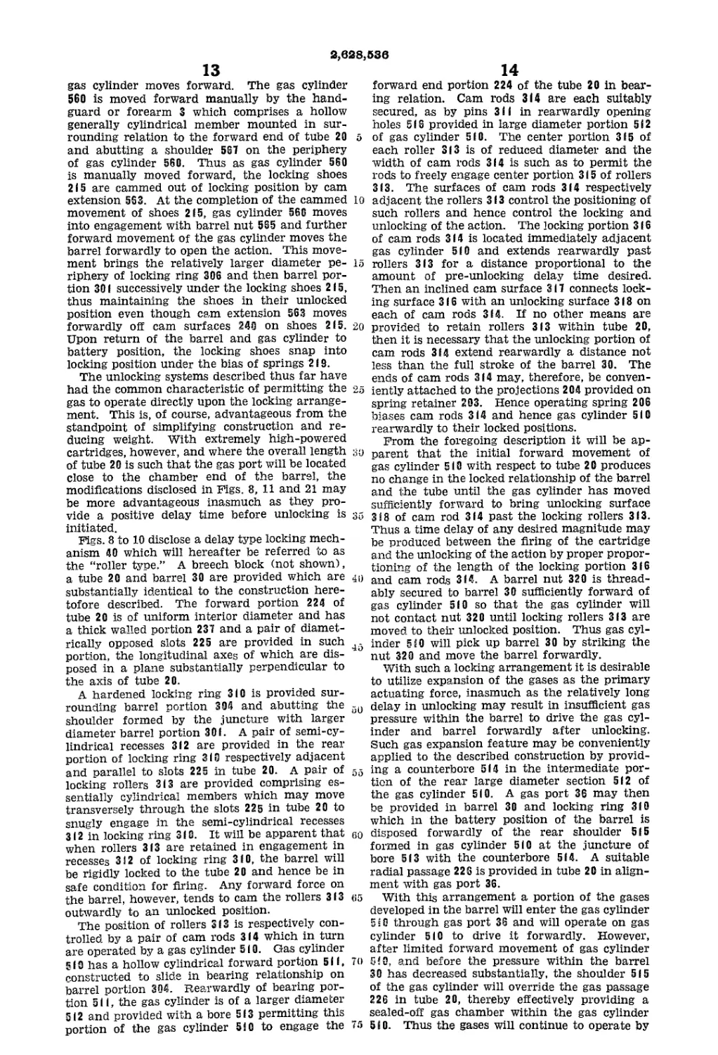
Figs. 8 to 10 disclose a delay type locking mech-
anism 40 which will hereafter be referred to as
the “roller type.” A breech block (not shown),
a tube 20 and barrel 30 are provided which are
substantially identical to the construction here-
tofore described. The forward portion 224 of
tube 20 is of uniform interior diameter and has
a thick walled portion 237 and a pair of diamet-
rically opposed slots 225 are provided in such
portion, the longitudinal axes of which are dis-
posed in a plane substantially perpendicular to
the axis of tube 20.
A hardened locking ring 3(0 is provided sur-
rounding barrel portion 304 and abutting the
shoulder formed by the juncture with larger
diameter barrel portion 30(. A pair of semi-cy-
lindrical recesses 3(2 are provided in the rear
portion of locking ring 3(0 respectively adjacent
and parallel to slots 225 in tube 20. A pair of 55
locking rollers 3(3 are provided comprising es-
sentially cylindrical members which may move
transversely through the slots 225 in tube 20 to
snugly engage in the semi-cylindrical recesses
3(2 in locking ring 3(0. It will be apparent that eo
when rollers 3(3 are retained in engagement in
recesses 312 of locking ring 3(0, the barrel will
be rigidly locked to the tube 20 and hence be in
safe condition for firing. Any forward force on
the barrel, however, tends to cam the rollers 3(3
outwardly to an unlocked position.
The position of rollers 3 (3 is respectively con-
trolled by a pair of cam rods 3 (4 which in turn
are operated by a gas cylinder 5(0. Gas cylinder
5 (0 has a hollow cylindrical forward portion 5(1,
constructed to slide in bearing relationship on
barrel portion 304. Rearwardly of bearing por-
tion 5i i, the gas cylinder is of a larger diameter
5(2 and provided with a bore 5(3 permitting this
portion of the gas cylinder 510 to engage the
14
forward end portion 224 of the tube 20 in bear-
ing relation. Cam rods 3(4 are each suitably
secured, as by pins 3(1 in rearwardly opening
holes 5 (6 provided in large diameter portion 5 (2
of gas cylinder 5(0. The center portion 3(5 of
each roller 3(3 is of reduced diameter and the
width of cam rods 3(4 is such as to permit the
rods to freely engage center portion 3 i 5 of rollers
3(3. The surfaces of cam rods 3(4 respectively
adjacent the rollers 3 (3 control the positioning of
such rollers and hence control the locking and
unlocking of the action. The locking portion 3 (6
of cam rods 3(4 is located immediately adjacent
gas cylinder 5(0 and extends rearwardly past
rollers 3(3 for a distance proportional to the
amount of pre-unlocking delay time desired.
Then an inclined cam surface 3 i 7 connects lock-
ing surface 3 (6 with an unlocking surface 3 (8 on
each of cam rods 3(4. If no other means are
provided to retain rollers 3(3 within tube 20,
then it is necessary that the unlocking portion of
cam rods 3(4 extend rearwardly a distance not
less than the full stroke of the barrel 30. The
ends of cam rods 3(4 may, therefore, be conven-
25 iently attached to the projections 204 provided on
spring retainer 203. Hence operating spring 206
biases cam rods 3(4 and hence gas cylinder 5(0
rearwardly to their locked positions.
From the foregoing description it will be ap-
30 parent that the initial forward movement of
gas cylinder 5 i 0 with respect to tube 2 0 produces
no change in the locked relationship of the barrel
and the tube until the gas cylinder has moved
sufficiently forward to bring unlocking surface
35 318 of cam rod 3(4 past the locking rollers 3(3.
Thus a time delay of any desired magnitude may
be produced between the firing of the cartridge
and the unlocking of the action by proper propor-
tioning of the length of the locking portion 3(6
ill and cam rods 3(4. A barrel nut 320 is thread-
ably secured to barrel 30 sufficiently forward of
gas cylinder 5(0 so that the gas cylinder will
not contact nut 320 until locking rollers 3(3 are
moved to their unlocked position. Thus gas cyl-
45 inder 5(0 will pick up barrel 30 by striking the
nut 320 and move the barrel forwardly.
With such a locking arrangement it is desirable
to utilize expansion of the gases as the primary
actuating force, inasmuch as the relatively long
delay in unlocking may result in insufficient gas
pressure within the barrel to drive the gas cyl-
inder and barrel forwardly after unlocking.
Such gas expansion feature may be conveniently
applied to the described construction by provid-
ing a counterbore 5(4 in the intermediate por-
tion of the rear large diameter section 5(2 of
the gas cylinder 5(0. A gas port 36 may then
be provided in barrel 30 and locking ring 3(0
which in the battery position of the barrel is
disposed forwardly of the rear shoulder 5(5
formed in gas cylinder 5(0 at the juncture of
bore 5(3 with the counterbore 5(4. A suitable
radial passage 226 is provided in tube 20 in align-
ment with gas port 36.
65 With this arrangement a portion of the gases
developed in the barrel will enter the gas cylinder
5sG through gas port 36 and will operate on gas
cylinder 5(0 to drive it forwardly. However,
after limited forward movement of gas cylinder
70 5!0, and before the pressure within the barrel
30 has decreased substantially, the shoulder 5(5
of the gas cylinder will override the gas passage
226 in tube 20, thereby effectively providing a
sealed-ой gas chamber within the gas cylinder
"5 510. Thus the gases will continue to operate by
2,628,636
15
expansion to accelerate the gas cylinder 510 for-
wardly, thereby unlocking locking rollers 313 and
picking up the barrel 30 by collision with barrel
nut 3SS. Just beyond this point the rear end of
gas cylinder 510 will pass ой the forward end of
tube 20 and exhaust the residual gases. The
barrel, however, has received sufficient accelera-
tion to carry it to its extreme forward position as
illustrated in Fig. 9, compressing operating spring
206.
On the return stroke operating spring 206
functions on barrel 30 through the engagement
of gas cylinder 5! 0 with the forward end of lock-
ing ring 310. The cam surfaces 317 on cam rods
314 will therefore strike the rollers 313 prior to
the barrel reaching its battery position. While
this interrupts the spring action of operating
spring 206 upon the barrel, the barrel, due to its
large mass, has more than sufficient momentum
to permit it to coast into its battery position.
Hence a spring bias will be maintained on the
rollers 313 which will snap them into locked
position in the recesses 312 when the barrel coasts
into its battery position.
Quantity production models—gas operated, posi-
tive lock, automatic rifles
Referring to Figs. 11 through 25, there will now
be described modifications of this invention com-
prising gas operated, positive lock, automatic fire-
arms which have been designed in such manner
as to be readily adaptable to quantity production,
inasmuch as all of the major elements of the
rifle are either cylindrical components or stamp-
ings.
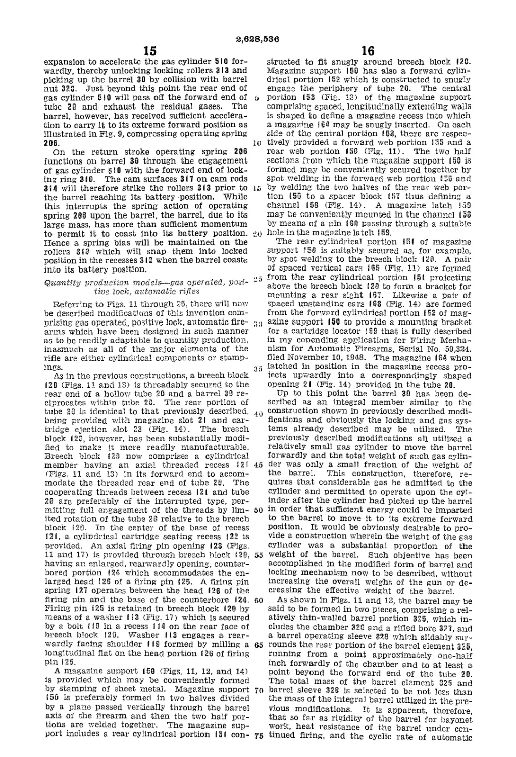
As in the previous constructions, a breech block
120 (Figs. 11 and 13) is threadably secured to the
rear end of a hollow tube 20 and a barrel 38 re-
ciprocates within tube 28. The rear portion of
tube 28 is identical to that previously described,
being provided with magazine slot 21 and car-
tridge ejection slot 23 (Fig. 14). The breech
block 120, however, has been substantially modi-
fied to make it more readily manufacturable.
Breech block S 2Э now comprises a cylindrical
member having an axial threaded recess 121
(Figs. 11 and 13) in its forward end to accom-
modate the threaded rear end of tube 2S. The
cooperating threads between recess 121 and tube
28 are preferably of the interrupted type, per-
mitting full engagement of the threads by lim-
ited rotation of the tube 28 relative to the breech
block (20. In the center of the base of recess
!2I, a cylindrical cartridge seating recess 122 is
provided. An axial firing pin opening 123 (Figs.
11 and 17) is provided through breech block !28,
having an enlarged, rearwardly opening, counter-
bored portion 124 which accommodates the en-
larged head !2S of a firing pin i 25. A firing pin
spring 127 operates between the head 126 of the
firing pin and the base of the counterbore 124.
Firing pin 125 is retained in breech block 120 by
means of a washer 113 (Fig. 17) which is secured
by a bolt i IS in a recess I IS on the rear face of
breech block 180. Washer 113 engages a rear-
wardly facing shoulder 119 formed by milling a
longitudinal flat on the head portion 126 of firing
pin 125.
A magazine support 150 (Figs. 11, 12, and 14)
is provided which may be conveniently formed
by stamping of sheet metal. Magazine support
150 is preferably formed in two halves divided
by a plane passed vertically through the barrel
axis of the firearm and then the two half por-
tions are welded together. The magazine sup-
port includes a rear cylindrical portion 151 con-
&
io
15
20
25
30
35
40
45
50
55
60
65
70
75
16
structed to fit snugly around breech block 120.
Magazine support (58 has also a forward cylin-
drical portion 152 which is constructed to snugly
engage the periphery of tube 28. The central
portion 153 (Fig. 13) of the magazine support
comprising spaced, longitudinally extending walls
is shaped to define a magazine recess into which
a magazine 164 may be snugly inserted. On each
side of the central portion 153, there are respec-
tively provided a forward web portion 155 and a
rear web portion IS6 (Fig. 11). The two half
sections from which the magazine support ISO is
formed may be conveniently secured together by
spot welding in the forward web portion ! 55 and
by welding the two halves of the rear web por-
tion 158 to a spacer block (57 thus defining a
channel 158 (Fig. 14). A magazine latch 159
may be conveniently mounted in the channel 158
by means of a pin (SB passing through a suitable
hole in the magazine latch ! 59.
The rear cylindrical portion 151 of magazine
support (58 is suitably secured as, for example,
by spot welding to the breech block 120. A pair
of spaced vertical ears 1S5 (Fig. 11) are formed
from the rear cylindrical portion 15! projecting
above the breech block 120 to form a bracket for
mounting a rear sight 1S7. Likewise a pair of
spaced upstanding ears 168 (Fig. 14) are formed
from the forward cylindrical portion 152 of mag-
azine support 150 to provide a mounting bracket
for a cartridge locator 168 that is fully described
in my copending application for Firing Mecha-
nism for Automatic Firearms, Serial No. 59,324.
filed November 10, 1948. The magazine 164 when
latched in position in the magazine recess pro-
jects upwardly into a correspondingly shaped
opening 21 (Fig. 14) provided in the tube 20.
Up to this point the barrel 30 has been de-
scribed as an integral member similar to the
construction shown in previously described modi-
fications and obviously the locking and gas sys-
tems already described may be utilized. The
previously described modifications all utilized a
relatively small gas cylinder to move the barrel
forwardly and the total weight of such gas cylin-
der was only a small fraction of the weight of
the barrel. This construction, therefore, re-
quires that considerable gas be admitted to the
cylinder and permitted to operate upon the cyl-
inder after the cylinder had picked up the barrel
in order that sufficient energy could be imparted
to the barrel to move it to its extreme forward
position. It would be obviously desirable to pro-
vide a construction wherein the weight of the gas
cylinder was a substantial proportion of the
weight of the barrel. Such objective has been
accomplished in the modified form of barrel and
locking mechanism now to be described, without
increasing the overall weight, of the gun or de-
creasing the eflective weight of the barrel.
As shown in Figs. 11 and 13, the barrel may be
said to be formed in two pieces, comprising a rel-
atively thin-walled barrel portion 325, which in-
cludes the chamber 328 and a rifled bore 327, and
a barrel operating sleeve 328 which slidably sur-
rounds the rear portion of the barrel element 325,
running from a point approximately one-half
inch forwardly of the chamber and to at least a
point beyond the forward end of the tube 20.
The total mass of the barrel element 325 and
barrel sleeve 328 is selected to be not less than
the mass of the integral barrel utilized in the pre-
vious modifications. It is apparent, therefore,
that so far as rigidity of the barrel for bayonet
work, heat resistance of the barrel under con-
tinued firing, and the cyclic rate of automatic
2,628,538
17
fire of the weapon are concerned, this two-piece
barrel construction will function equally as well
as the previously described integral construction.
As a matter of fact the cooling rate of such bar-
rel will be somewhat greater inasmuch as relative
movement (which will be described) between the
sleeve 328 and the barrel element 325 permits
exposure of a hotter portion of the barrel for air-
cooling, yet does not impair the loss of heat from
the barrel by conduction.
Barrel element 325 is formed with essentially
three distinct diameters, the largest diameter
portion 329 comprises the extreme rear end of
the barrel element 325 and is of such diameter
as to permit large diameter portion 329 to coop-
erate in bearing relationship with the uniform
diameter bore 230 of the tube 20. This large
diameter portion 329 is of limited length, being
just long enough to accommodate the threaded
hole in which the cocking rod 600 is secured into
the barrel. Next, an intermediate diameter por-
tion 330 is provided which preferably extends for-
wardly to a point beyond the forward end of
the magazine opening 21 in tube 20. Finally,
the remainder of the forward portion of the
barrel element 325 is preferably of substantially
uniform small diameter 331. A substantial sized
forwardly facing shoulder ?32 is thereby formed
at the juncture pf diameter portions 330 and 331
which will be utilized as a locking shoulder for
the barrel. It is desired to point out that while
shoulder 332 is preferably located to lie forwardly
of the magazine opening in the tube when the
barrel is fn its battery position, in some appli-
cations of this invention it may be desirable to
move such ghpulder back further along the bar-
rel, This, pf course, has the effect of moving the
point of locking of the action closer to the face
of the breech member.
The barrel sleeve 328 has a uniform exterior
diameter 333 which cooperates in bearing rela-
tionship with the uniform diameter bore 230 of
the tube 20, The bore of sleeve 328 is formed
in two diameters, a rearward large diameter por-
tions 33^ which cooperates with the intermediate
portion pf the barrel element 325 and a forward
smaller diameter portion 335 (Fig. 11) which
cooperates in bearing relationship with the small
diameter portion 331 of the barrel element 325.
The extreme forward end of barrel sleeve 328
is provided with threads 336 which project beyond
the end of tube 20. An annular gas cylinder 520
is provided with a forward threaded portion 517
which engages the thread 336 on barrel sleeve 328
and a rearwardly extending cylinder portion 518
which cooperates in bearing relationship with a
bushing 231 which is secured by a key 363 to the
forward end of tube 20. Thus in effect the gas
cylinder is supplied with a mass that is a sub-
stantial proportion of the mass of the barrel ele-
ment 325.
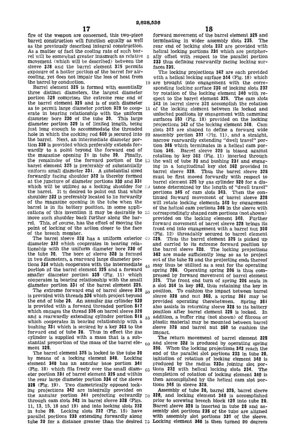
The barrel element 325 is locked to the tube 20
by means of a locking element 340. Locking
element 340 has an annular base portion 341
(Fig. 18) which fits freely over the small diam-
eter portion 331 of barrel element 325 and within
the rear large diameter portion 334 of the sleeve
328 (Fig. 19). Two diametrically opposed lock-
ing projections 342 are integrally provided on
the annular portion 341 projecting outwardly
through cam slots 343 in barrel sleeve 328 (Figs.
11, 13, 15, 18 and 19) and into locking slots 232
in tube 20. Locking slots 232 (Fig. 15) have
parallel portions 233 extending forwardly along
tube 20 for a distance greater than the desired
10
15
20
t'j
45
50
55
60
G5
70
75
18
forward movement of the barrel element 325 and
terminating in wider assembly slots 235. The
rear end of locking slots 232 are provided with
helical locking portions 234 which are peripher-
ally offset with respect to the parallel portion
233 thus defining rearwardly facing locking sur-
faces 23S.
The locking projections 342 are each provided
with a helical locking surface 344 (Fig. 18) which
are brought into engagement with the corre-
sponding locking surface 236 of locking slots 232
by rotation of the locking element 340 with re-
spect to the barrel element 325. The cam slots
343 in barrel sleeve 328 accomplish the rotation
of the locking element between its locked and
unlocked positions by engagement with camming
surfaces 353 (Fig. 18) provided on the locking
projections 342 of the locking element 340. Cam
slots 343 are shaped to define a forward wide
assembly portion 337 (Fig. 11), and a straight,
narrow rearwardly extending “dwell travel” por-
tion 345 which terminates in a helical cam por-
tion 346. Barrel sleeve 328 is biased against
rotation by key 363 (Fig. 11) inserted through
the wall of tube 20 and bushing 231 and engag-
ing in a longitudinal key slot 362 provided in
barrel sleeve 328. Thus the barrel sleeve 328
must be first moved forwardly with respect to
barrel element 325 by gas cylinder 520 for a dis-
tance determined by the length of “dwell travel”
portions 345 of cam slots 343. Then the con-
tinued forward movement of barrel sleeve 328
will rotate locking elements 340 by engagement
of the helical cam portions 346 in the sleeve with
correspondingly shaped cam portions (not shown)
provided on the locking element 340. Further
forward movement of barrel sleeve 328 brings its
front end into engagement with a barrel nut 360
(Fig. 12) threadably secured to barrel element
325. Thus ths barrel element 325 is picked up
and carried to its extreme forward position by
the barrel sleeve 328. Tire locking projections
342 are made sufficiently long so as to project
out of the tube 20 and the projecting ends thereof
may thus be utilized as a seat for the operating
spring 206. Operating spring 206 is thus com-
pressed by forward movement of barrel element
325. The front end turn of spring 206 seats in
a slot 364 in key 363, thus retaining the key in
position. To cushion the impact between barrel
Sleeve 328 and nut 360, a spring 361 may be
provided operating therebetween. Spring 361
also assists in returning sleeve 328 to its battery
position after barrel element 325 is locked. In
addition, a buffer ring (not shown) of fibrous or
plastic material may be mounted between barrel
sleeve 328 and barrel nut 360 to cushion the
impact.
The return movement of barrel element 325
and sleeve 328 is produced by operating spring
206. When the locking projections 342 reach the
end of the parallel slot portions 233 in tube 20,
initiation pf rotation pf locking element 340 is
produced by the radius 233u joining slot por-
tions 233 with helical locking slots 234. The
completion of rotation of locking element 340 is
then accomplished by the helical cam slot por-
tions .346 in sleeve 328.
Assembly of tube 20, barrel 325, barrel sleeve
328, and locking element 340 is accomplished
prior to screwing breech block 120 into tube 20.
Barrel sleeve 328 is inserted in tube 20 and as-
sembly slot portions 235 of the tube are aligned
with assembly slot portions 337 of the sleeve.
Locking element 340 is then turned 50 degrees
3.628.536
19
from its normal position, inserted through the
assembly slots, and then rotated 90 degrees back
to its normal position. Barrel element 325 may
then be inserted through the assembly from the
rear thereof with barrel portion 330 passing
through the annular portion Зв I of the locking
element.
To eliminate the necessity for a high degree
of precision in the longitudinal location of lock-
ing slots 232 relative to the barrel locking shoul-
der 332, a headspace washer 338 is provided be-
tween barrel locking shoulder 332 and locking
element 340. The headspacing of the firearm
may then be readily and conveniently accom-
plished by selection of the thickness of washer
338. Washer 338 is preferably formed of an
anti-friction metal such as brass, to facilitate
rotation of locking element ЗвО.
In operation, after the firing of a cartridge
barrel sleeve 328 is moved forwardly by gases
supplied to gas cylinder 520 through barrel port
348 and a hole 349 in barrel sleeve 328 which
are aligned in the battery position. After limited
forward movement of barrel sleeve 328, the hole
349 moves out of alignment with barrel port 348
and hence seals off barrel port 348. Thus a
sealed, expansion chamber is provided within
gas cylinder 520, permitting the gases trapped
therein to expand and accelerate gas cylinder
520 forwardly, independent of the rapid drop in
barrel bore pressure, until the rear end of gas
cylinder 520 passes off the forward end of
bushing 231. It will be noted that a large ex-
haust passage area is thus opened, insuring
complete exhaust of the gases and thereby re-
ducing the tendency for deposits of carbon to
form within the gas cylinder.
The sealing-off feature of the gas system per-
mits the launching of grenades without special
safety arrangements inasmuch as the operation
of the gas system is independent of the length of
time that pressure is maintained within the
barrel bore.
A slot 354 is provided in the top surface of
barrel sleeve 328 overlying a groove 321 in barrel
element 325 which operates cartridge locator
169. Thus cartridge locator 169 serves to main-
tain barrel element 325, barrel sleeve 328, and
tube 26 in fixed rotational alignment in all posi-
tions of barrel element 325.
The simplicity of construction and the func-
tional advantages of the locking system just
described are deemed to be obvious. Without
detracting from the effective weight of the barrel,
the described locking arrangement imparts to
the gas cylinder an effective mass which is a
substantial portion of the mass of the barrel ele-
ment. Thus the acceleration of the gas cylinder
520 to a moderate velocity will store sufficient
kinetic energy in such cylinder to insure that
the barrel element 325 will be moved to its ex-
treme forward position. The locking element 340
serves the dual purpose of a lock and a spring
seat. It should also be noted that the length
of the “dwell” period of this improved action
for design purposes may be made extremely long
merely by increasing the length of the straight
portion 345 in cam slots 343, and moving back
the unlocking portions 346 relative to the bat-
tery position of locking element 340. In contrast
to conventional firearms of the gas operated,
rotary bolt type, a long “dwell” period may be
achieved without increasing the overall length
of the firearm.
Any desired form of quick detachable front
20
sight may be utilized with this improved fire-
arm. There is shown in Fig. 12 a front sight 94
comprising a hollow cylindrical body portion 95
which snugly surrounds the forward end of the
S barrel. An upstanding web portion 96 is pro-
vided on which a front sight blade 97 is pivotal-
ly secured. Body portion 95 is also provided
with a rearwardly extending alignment portion
98 which cooperates with a plane surface 339
30 provided on the barrel 30 to maintain the eight
in fixed angular relationship with respect to the
barrel. The sight 94 is secured to the barrel by
means of a flash hider 99 which is threadably
secured on threads 322 at the extreme end of the
15 barrel. Flash hider 99 abuts front sight 94 and
thus prevents its removal. Preferably a depend-
ing bayonet lug 323 is integrally formed on the
bottom of body portion 95 of sight 94 while the
flash hider 99 is provided with a forwardly pro-
20 jecting reduced diameter annular portion (not
shown). Thus a bayonet may be mounted to
the gun in conventional fashion through the
cooperation of the customary slot provided in
such bayonet (not shown) with the bayonet lug
25 323, and the bayonet ring (not shown) with the
annular portion of the flash hider.
The stock 86 utilized with this improved fire-
arm is preferably of the straight line type, that
is, no drop is provided, thereby increasing the
30 stability of the weapon under full automatic
firing conditions.
A pistol grip (not shown) is preferably pro-
vided which is secured to the bottom portion
of the stock behind the trigger by suitable screws.
35 The handguard 25 utilized in this modification
comprises a substantially semi-circular channel
member of suitable wood or plastic which sur-
rounds all of the tube or receiver 20 forwardly
of magazine support 150. Handguard 25 beds
40 upon the forward portion of the stock 86 and
is secured to the stock by a suitable split ring
type metallic ferrule member 26 which sur-
rounds both the stock 86 and handguard 25.
To facilitate manual operation of the firearm
action, the handguard and stock are preferably
terminated rearwardly of at least a portion of
the gas cylinder 520. A heat insulating sleeve
521 (Fig. 11) of suitable material is suitably se-
cured to gas cylinder 520 in surrounding re-
lationship, permitting the cylinder to be grasped
“° by the hand of the operator and thus the flre-
merely by manually pushing the gas cylinder
520 forwardly.
Assembly and disassembly of this modification
r_ is essentially similar to the procedure heretofore
00 described. It is necessary to remove the front
sight 99 only when it is desired to completely
separate the barrel element 325 from the tube
and operating sleeve. After removal of the barrel
nut 389 and front sight 94, the barrel element
00 325 may be moved rearwardly out of tube 2Э.
Locking element 340 may then be disassembled
by rotating it 90 degrees and withdrawal through
the cam slots 343 in barrel sleeve 328 and through
the locking slots 232 in tube 20.
85 It should be noted that the construction de-
scribed is particularly adaptable for large quan-
tity production inasmuch as all of the major ele-
ments are of cylindrical configuration such as
the breech block 120, the tube 20, the barrel ele-
7° ment 325, the barrel sleeve 328, the gas cylinder
526 and the handguard 3, or may be produced
from stampings, such as the magazine support
150 and trigger guard 53.
Referring to Figs. 20-25 there is disclosed a
75 further modification of this invention comprising
2,628,636
21
a receiver or tube 720 threadably secured at its
rear end to a breech block 700. Tube 720 is gen-
erally very similar in configuration to those uti-
lized in the other modifications of this invention
(see for example Fig. 15) and comprises a long
tubular member having a uniform diameter, in-
terior bore 723 and extends forwardly from the
breech block for a distance approximately equal
to one-half the length of the barrel. Approx-
imately the rear one-half portion of the tube has
a substantial wall thickness as represented by the
large diameter portion 724. The forward portion
725 (Fig. 21), however, has as thin a wall sec-
tion as consistent with the required strength of
the component. Ejection slot 72S (Fig. 20) is
provided in the rear top portion of the large
diameter section 725 of the tube and a maga-
zine slot (not shown) is provided in the bottom
of such tube portion.
Longitudinally extending slots 830 (Fig. 21)
are provided in the forward end of the tube 729
to accommodate the radially projecting arms 841
of an annular locking element 340. The slot 83Э
runs from the forward end of the large diameter
tube portion 723 to a point just short of the for-
ward end of the small diameter portion 725 of the
tube 720. The rear end of the slot 830 is ex-
tended transversely along a helical angle, ap-
proaching 90 degrees, to define a rearwardly fac-
ing locking shoulder 831. A camming radius 839a
is provided at the juncture of the straight and
helical slot portions which initiates rotation of
locking element 840 to its locked position. The
forward ends of the slots 830 are widened to pro-
vide assembly portions 832.
The barrel 730 utilized in this modification is
of extremely simple configuration, comprising a
rear maximum diameter portion 732 (Fig. 21)
extending from the face of breech block TOO to a
point just short of the location of the locking
shoulder 831 in the tube 720; next, a forwardly
extending reduced diameter portion 733 which
extends forwardly to a point beyond the end of
tube 720 and terminates in a threaded portion 734
to which a barrel nut 735 is secured, and then
a decreasing diameter tapered portion 735 (Fig.
20) terminating in suitable threads upon which
the flash hider S3 is mounted.
The maximum diameter portion 732 of the bar-
rel engages the bore 723 of the tube 720 in bear-
ing relation. The barrel is supported forwardly
on its reduced diameter portion 733 by a barrel
bearing 834 (Fig. 21) which is brazed or other-
wise suitably secured in the forward end of tube
720.
Immediately to the rear of the muzzle end of
the barrel, a fiat 737 (Fig. 20) is formed on the
barrel. A sight 94 and flash hider SS are mounted
on the forward end of the barrel 730. These ele-
ments are identical to those previously described
in connection with the modification shown in
Fig. 12.
The forwardly facing shoulder 738 (Fig. 21)
formed at the juncture of maximum diameter
barrel portion 732 with reduced diameter barrel
portion 733 is utilized as a locking shoulder. The
annular locking element 840 is slipped over barrel
portion 733 and abuts against locking shoulder
738 through a headspace washer 844 of selected
thickness. The radially projecting arms 341 of
locking element 840 (Fig. 25) each have a heli-
cal locking portion 842 formed thereon which
cooperates with locking shoulder 831 in the tube
720. The arms 841 project radially beyond the
maximum diameter portion 724 of the tube and
the projecting ends thereof are provided with
5
10
15
20
25
34
.35
40
45
50
55
60
65
70
75
22
helical camming surfaces 843 which are engaged
by suitable camming slots 745 provided in an
operating sleeve 740.
In contrast with the modification disclosed in
Fig. 11, the operating sleeve 749 (Figs. 21 and 24)
is mounted in surrounding relationship to the for-
ward end of the tube 720. This construction has
two advantages: first, an improved leverage con-
dition for producing rotation of locking element
849; secondly, less frictional resistance to move-
ment of the operating sleeve.
The operating sleeve 740 comprises an elon-
gated tubular portion having three stepped in-
terior and exterior diameter portions. The rear-
ward portion 74! is of largest diameter and is
constructed to surround the forward end of large
diameter portion 724 of tube 720. The v. all thick-
ness of portion 74! is preferably somewhat greater
than the rest of the operating sleeve due to the
fact that this portion contains the cam slots
745; next, is an intermediate diameter portion
742 which is constructed to surround the for-
ward reduced diameter portion 725 of tube 729 in
bearing relation: finally, the extreme forward
portion 743 of operating sleeve 749 is of the small-
est diameter and is constructed to engage bar-
rel portion 733 in bearing relation. The shoulder
744 formed at the juncture of intermediate por-
tion 742 and forward portion 743 of operating
sleeve 748 defines a gas cylinder wall for the
gun.
As has already been mentioned, a pair of op-
posed helical camming slots 74S (Fig. 24) are
provided in the rear portion 74 of the operat-
ing sleeve 748 which cooperate with the cam por-
tions 843 of the locking element 848. Connecting
with each cam slot 745 is a longitudinal slot 746
comprising a “dwell travel” slot and at the for-
ward end of the “dwell travel” slots, there is pro-
vided enlarged assembly slot portions 747. A
longitudinally extending key slot 748 (Figs. 21
and 22) is also provided in the rear portion 74 i
of the operating sleeve 74G which cooperates with
a key 833 which is threadably or otherwise rig-
idly secured to the large diameter portion 724
of the tube 723. A longitudinally extending slot
74S is also provided in the bottom portion of
operating sleeve 740 extending from a point a
half-inch or more behind the gas cylinder shoul-
der 744 rearwardly for a distance somewhat great-
er than the total forward travel of the oper-
ating sleeve. In the assembled firearm, this slot
surrounds a forearm bushing 785 (Fig. 21) which
will be described in more detail later.
In the battery positions of the barrel 730 and
the operating sleeve 740, the locking portions
842 of locking element 840 are rotated behind
the locking shoulders 831 of tube 720 and the
cam portions 843 of the locking element lie in
the “dwell travel” slot 746 of the operating sleeve
740. In this position a slight clearance 835
(Fig. 21) is provided between the extreme for-
ward end of tube 720 and the gas cylinder wall
744 which functions as a gas cylinder chamber.
A gas port 739 is provided in barrel 730 com-
municating with this clearance. Hence upon
discharge of a cartridge in the barrel, the gases
will enter the gas cylinder chamber 835 and
operate upon the gas cylinder wall 744 to drive
the operating sleeve 740 forwardly.
After a suitable “dwell travel,” which is
selected in consideration of the pressure char-
acteristics of the cartridge and the location of
the gas port relative to the chamber to insure
that the bore pressure is reduced to a safe value,
Й,628,636
23
the operating sleeve 740 moves sufficiently to
bring the camming slots 745 into engagement
with the cam portions 843 of the locking element
840. The locking element is thereupon rotated
to an unlocked position in which the locking
portions 842 lie in the longitudinal slots 830 in
the tube 720. At this point, or slightly there-
after, the forward end of the operating sleeve
740 makes operative engagement with the barrel
nut 735 and due to the high inertia of the oper-
ating sleeve, the barrel is picked up thereby and
moved forwardly, initiating its automatic cycle.
Preferably an annular buffer 825 is mounted on
barrel portion 733 between barrel nut 735 and
operating sleeve portion 740 to cushion the im- 15
pact between the operating sleeve and the barrel.
Likewise an annular buffer 292 may be provided
around barrel portion 733 to absorb the impact
between locking element 840 and barrel bearing
834. A spring 361 is mounted between buffer 20
825 and the forward end of operating sleeve 740
and provides a force urging operating sleeve to
its battery position relative to the barrel.
A magazine support 850 is provided which is
somewhat similar to the magazine support 150 25
described in connection with the modification
shown in Figs. 11, 13, and 14. Magazine sup-
port 850 is preferably formed from two pressed
metal half parts which in assembly lie respec-
tively on each side of a plane passing vertically зп
through the barrel axis of the firearm.
The central portion 858 of magazine support
850 comprises spaced walls which are shaped to
define a magazine recess (not known) into which
a magazine 164 may be snugly inserted. "5
On each side of the central portion 858 of the
magazine support, there are respectively pro-
vided a forward web portion 862 and a rear web
portion 863. The two half sections from which
the magazine support 850 is formed may be con- 4<'.
veniently secured together by spot welding in
the forward web portion 862 and by welding the
two halves of portion 863 to a spacer block (not
shown) which thus defines a channel (not
shown). 45
A straight line stock 770 is preferably utilized
with this firearm being provided with a conven-
tional butt plate 884 and a sling swivel 885 may
be suitably secured to the bottom portion of
stock 770. It will be apparent that, while stock 50
770 may be fabricated from wood, it is readily
adapted to fabrication from molding of a suit-
able plastic material. A metallic pistol grip
member 886 is provided, preferably of a U-shaped
cross section, and arranged with its open por-
tion facing the rear. A trigger guard 53 is pro-
vided which may be conveniently formed by
stamping comprising an elongated strip-like
member.
The forearm 780 may be conveniently formed
from either wood or plastic and comprises a
longitudinally extending member of generally
rectangular exterior cross-section and having a
longitudinal bore 781 which freely surrounds
operating sleeve 740. The forearm is secured 65
to the firearm at two points. At the rear of the
forearm, a transverse hole 782 is provided in the
top portion thereof which in assembly aligns
with transverse holes (not shown) provided in
the forward portion of the magazine support 850. 70
24
ating sleeve 740 into engagement with the bot-
tom of the forward, reduced diameter portion
725 of the tube 720. The top surface 786 of
forearm bushing 785 is arcuately shaped to
5 snugly engage the periphery of the tube portion
725. The bushing 785 comprises an inverted
cup-shaped member having a large cylindrical
bore 787 open at the bottom thereof and a gen-
erally rectangular slot 783 passing through its
base portion. A forearm retaining plunger 784
cooperates between forearm bushing 785 and
tube 720 to secure the forearm and tube together.
The plunger 784 is provided with a cylindrical
head portion 826, an intermediate cylindrical
shank portion 827 and at its upper end, a gen-
erally rectangular latch portion 828. The latch
portion 828 is constructed to pass through the
rectangular slot 783 and through an aligned
rectangular slot 836 which passes through both
the wall of tube 720 and barrel bearing 834. A
spring 29 is mounted in surrounding relation to
shank portion 827 and operates between the base
of the bore 787 of the forearm bushing and the
head portion 826 of the plunger. A cylindrical
counterbore 837 is provided in the interior wall
of barrel bearing 834 is alignment with the rec-
tangular slot 836. The counterbore 837 is of suf-
ficient depth so that when the rectangular latch
portion 828 of the plunger is inserted through
the slot 836, the entire plunger can be rotated 90
degrees, the latch portion 828 rotating within
the counterbore 837 to seat in a circumferential
groove 838 provided in the interior wall of barrel
bearing 834. Thus the forearm and tube 720 are
securely latched together. To disassemble, it is
only necessary to push forearm retaining plunger
784 upwardly, so that the latch, portion thereof
enters the counterbore 837, then rotate the
plunger 90 degrees and withdraw it through
rectangular slot 836. A front sling swivel 839
is preferably pivotally mounted to the projecting
end of the head portion 826 of the forearm re-
taining plunger 784. Swivel 839 thus provides
a convenient handle for manual operation of the
retaining plunger.
A manual operating handle 82Я may be secured
to operating sleeve 74Э at any convenient point,
such for example, as by welding it to the for-
ward reduced diameter portion 743 of operating
sleeve 740. A longitudinal slot 739 is provided
in forearm 780 to accommodate operating handle
C29.
In the last modification described, there has
been incorporated one structural feature which
55 can be advantageously utilized to produce an ad-
ditional forward acting force on the barrel to
fvfs’st the forward movement thereof after un-
locking has been effected. This feature arises
from the location of the breech block face (not
60 shown) within a recess in the breech block 703.
Since the tube 729 is threadably secured in the
threaded recess of the breech block 709, and
since the rear end of barrel 730 slides in bearing
relation with respect to tube 729, then, in effect,
a closed gas cylinder chamber is provided about
the rear end of barrel 733 while it is in its bat-
tery position and for a distance of about one-half
inch forward of its battery position. Further-
more, the barrel, in effect, constitutes a piston
movable in such chamber.
Near the forward end of the forearm, and
preferably in the bottom thereof, a forearm bush-
ing 785 (Figs. 21 and 23) is pressed or otherwise
rigidly secured in the wall of the forearm and
projects upwardly through the slot. 749 in oper- 7
if the “dwell” time of the firearm be made
very small, by proportioning of the “dwell travel”
slots 746 of operating sleeve 749, then it is possi-
ble to unlock the action while there is still a
5 substantial gas pressure within the barrel, yet
2,628,536
25
not sufficient pressure to produce a rupture of
the cartridge case. As the barrel starts to move
forwardly, the obturating seal of the cartridge
against the barrel chamber is broken, and the
residual gases can flow rearwardly around the
cartridge case into the closed gas cylinder cham-
ber defined by the tube, barrel, and breech block.
Thus, such residual gas pressures can operate
upon the substantial area of the end of the
barrel; imparting a forward force thereto to
assist the action of the operating sleeve 740.
Gas operated, lockless automatic rifle
It has already been mentioned that a firearm
action built around a forwardly movable barrel,
may, for some cartridges, permit a design wherein
no positive lock is required between the barrel
and the fixed breech member, the mass of the
barrel being proportioned with respect to the
forward forces on the barrel developed by the
cartridge so that the barrel does not move for-
wardly any substantial amount until after the
pressure within the barrel is reduced to a safe
value. Figs. 26 and 27 illustrate a specific appli-
cation of that phase of this invention to a firearm
designed to fire medium powered cartridges such,
for example, as the U. S. carbine, cal. .30, Ml.
This cartridge has sufficient power that a posi-
tive lock, rotating bolt-type action is commonly
utilized to fire it. If, however, a conventional
“blow-back” action were applied to this cartridge,
the bolt would have to weigh on the order of
two pounds. This would obviously prevent the
successful design of a firearm for this cartridge
where the maximum weight requirement is in the
neighborhood of five pounds. However, by the
application of this invention, a safe action is
obtained having an overall weight of less than
five pounds, even with a substantially heavier
barrel than that commonly employed.
Referring to Figs. 26 and 27, the breech block
IS, magazine 164, hammer 635, trigger 617, ex-
tractor (not shown), ejector (not shown), firing
pin ISO, cocking rods 755, hammer springs 735,
operating spring 206, magazine latch 76, etc., are
similar to those fully described in my eo-pending
application for Firing Mechanism for Automatic
Firearms. Serial No, 59,324, filed November 10,
1948, however being of reduced dimensions pro-
portional to the reduction in the size and energy
of the cartridge. These components will there-
fore not be again described. The barrel 359
utilized in this modification is of exceedingly
simple configuration having an enlarged diameter
portion 351 at its rear end and a substantially
uniform diameter portion 352 extending forward
to the muzzle. Tire tube 259 is likewise of very
simple configuration having a threaded portion
25! at the rear end thereof to threadably engage
in the breech recess 11 and having an enlarged
rear bore portion 252 and a smaller diameter for-
ward bore portion 253 (Fig. 27), which portions
cooperate in bearing relationship respectively
with diametrical portions 35! and 352 of the
barrel. A spring retainer 233 identical to that
previously described is provided which seats
against the shoulder 357 formed at the juncture
of barrel portions 35! and 352. Preferably an
additional operating spring 206 is provided func-
tioning between spring retainer 203 and a ring-
like member 254 secured on the forward end of
tube 259 and thus supplementing the resistance
of hammer springs 795 to forward movement of
the barrel. An annular buffer 202 may be pro-
vided surrounding barrel portion 352.
5
10
15
20
!',0
35
40
45
50
55
00
05
70
75
26
The extreme forward portion 255 of tube 250
is of uniform diameter and functions as a fixed
piston with respect to a gas cylinder 550. Gas
cylinder 550 is an annular member preferably
having a forward, interiorly threaded portion 55!
secured to a threaded portion 358 on barrel 350
and an enlarged rear bore portion 552 which
slides over piston portion 255 of the tube in
the battery position of the barrel. A gas port
359 is provided in barrel 355 communicating with
the interior of gas cylinder 550. Gas port 359
is located on barrel 35G forwardly of the region
wherein maximum gas pressure is developed. Al-
ternatively, gas cylinder 550 may be connected to
the barrel in a manner similar to the construc-
tion of Fig. 6, i. e., the cylinder may slide on
barrel 350 and engage a suitable nut member
secured to the barrel.
The mass of barrel 350 is selected by propor-
tioning the dimensions thereof relative to the
forward forces developed by the cartridge so
that upon the firing of a cartridge, the inertia
mass of the barrel is sufficient to insure very
slow acceleration of the barrel under the for-
ward forces of both the cartridge and the gas
cylinder. The operating springs 795 and 206
of course are in opposition to such forward
forces and hence reduce the amount of mass
required in the barrel. Thus the barrel does not
move forward any substantial distance until
after the cartridge has passed out of the muzzle
and the gas pressure is reduced to a safe value.
The barrel, however, receives sufficient energy
from the pressure forces acting on it and from
gas cylinder 550 to insure that it will move out
to its extreme forward position, thereby accom-
plishing extraction and ejection of the cartridge
case and cocking of the hammer mechanism.
The barrel is then returned rearwardly by com-
pressed hammer springs 795 and operating
spring 206, loading the top cartridge from mag-
azine 164 whereupon the next round may be
fired either automatically or semi-automatically
depending on the condition of the trigger mech-
anism.
Thus by this design the entire mass of the
barrel contributes to the safety of the auto-
matic action and reduction of the rate of fire
of the weapon. No additional heavy breech
member is required, hence the over-all weight
of the gun may be maintained or reduced over
conventional actions even with a substantially
increased barrel weight.
It is desired to point out that, depending on
the cartridge design and characteristics, the gas
cylinder may be eliminated or its forward ac-
tion greatly supplemented by utilization of the
residual gas pressure against the rear face of
the barrel in the manner heretofor discussed in
connection with other modilcations of this in-
vention. Here, as in the other modifications,
the rear end portion of the tube 259 surrounds
the rear end of barrel 350 in gas sealing rela-
tionship. Thus when the barrel moves for-
wardly sufficiently to break the gas seal between
the expanded cartridge and the interior surface
of the chamber, the residual gases escape back
past the cartridge and operate upon the rear
end of the barrel as a piston, the breech block
and tube acting as a gas cylinder with respect
to the barrel. The effectiveness of this force, of
course, depends upon the time required to break
the cartridge obturation seal, which in this case
is dependent upon the selected mass of the bar-
rel.
2,628,636
28
member to said barrel after the unlocking thereof
whereby said barrel is moved forwardly.
3. In an automatic firearm, a hollow tubular
receiver, a breech member secured to the rear
5 portion of said receiver, a barrel slidably sup-
ported in said receiver for forward movement
relative to said breech member, means for locking
said, barrel to said receiver in the battery position
cf said barrel, means responsive to the gas pres-
1-Э sure generated in said barrel by the discharge
of a cartridge therein for unlocking said locking
means to release said barrel from said receiver,
said barrel having a gas port therein adjacent
the forward end of said receiver, an annular gas
15 cylinder member slidably mounted on said barrel
for forward movement relative thereto, said gas
cylinder member having an annular portion co-
operating with the forward end of said receiver
to define a gas cylinder chamber communicating
•20 with said gas port whereby said gas cylinder
member is driven forwardly by the gas pressure,
and a nut member secured to said barrel in the
path of forward movement of said gas cylinder
member whereby said barrel is moved forwardly
25 by said gas cylinder member after the unlocking
of said barrel.
4. In an automatic firearm, a hollow tubular
receiver, a breech member secured to the rear
portion of said receiver, a barrel slidably sup-
;{0 ported in said receiver for forward movement
relative to said breech member, means for locking
said barrel to said receiver in the battery posi-
tion of said barrel, said barrel having a gas port
therein adjacent the forward end of said receiver,
35 an annular gas cylinder member slidably mount-
ed on said barrel for forward movement relative
thereto, said gas cylinder member having an
annular portion surrounding the forward end of
said receiver to define a gas cylinder chamber
40 communicating with said gas port, whereby said
gas cylinder member is driven forwardly by the
gas pressure, said gas cylinder member including
means for unlocking said locking means by the
forward movement of said gas cylinder member
to release said barrel from said receiver, and a
'J nut member secured to said barrel in the path
of forward movement of said gas cylinder mem-
ber whereby said gas cylinder member contacts
said nut member after effecting unlocking of said
barrel to move said barrel forwardly.
5. In an automatic firearm, a hollow tubular
receiver, a breech member secured to the rear
portion of said receiver, a barrel slidably sup-
ported in said receiver for forward movement
relative to said breech member, said receiver
5 having a plurality of axially coplanar, radial holes
spaced about the periphery and opening into the
interior bore thereof, a generally cylindrical pis-
ton mounted in each of said holes for axial move-
ment therein, resilient means urging said pistons
inwardly, said barrel having a plurality of radial,
axially coplanar gas ports therein and counter-
bored recesses concentric with each of said gas
ports, said recesses being constructed and ar-
ranged to respectively receive the inwardly pro-
jecting ends of said pistons therein in the battery
positions of said barrel and receiver, each of said
pistons having a shoulder adjacent their outer
ends, a manually operable unlocking sleeve
70 mounted in surrounding relation on said tubular
receiver adjacent said, pistons, and a plurality
of camming surfaces on said unlocking sleeve
respectively engageable with said shoulder on said
pistons, said camming surfaces being constructed
75 and arranged to move said pistons radially out-
27
It should be noticed that in all of the described
modifications the barrel, even in battery posi-
tion is fioatingly supported in the tube and no
non-symmetrical transverse forces are exerted
on the barrel during the firing cycle as will be
apparent to those skilled in the art, such mount-
ing of the barrel greatly increases its accuracy
by elimination of interference with the natural
whip of the barrel. Thus the accuracy of mov-
ing barrel firearms embodying this invention
surpasses many conventional weapons having
barrels rigidly secured to the receiver.
It is desired to distinctly point out that var-
ious mechanisms disclosed herein may be ad-
vantageously applied to firearms utilizing actions
other than the forwardly moving barrel type.
Thus any or all of the locking mechanism con-
structions could be applied to firearms with con-
ventional actions and it is intended that such
applications of individual elements of this in-
vention be included in the scope thereof.
It will, therefore, be apparent that -applica-
tion of the principles of this invention provides
novel and improved firearm constructions which
permit automatic firearm designs which are out-
standingly characterized by a small number of
parts and simplicity of configuration of such
parts. Furthermore, due to the substantially
reduced locking forces which are inherent in
firearms embodying the principles of this in-
vention, the individual components may be made
much lighter without rendering the weapon un-
safe and accordingly a substantial reduction of
over-all weight of the firearm is achieved, which
is particularly important in military applica-
tions.
I claim:
1. In an automatic firearm, a hollow tubular
receiver, a breech member secured to the rear
portion of said receiver, a barrel slidably sup-
ported in said receiver for forward movement
relative to said breech member, means for locking
said barrel to said receiver in the battery position
of said barrel, means responsive to the gas pres-
sure generated in said barrel by the discharge
of a cartridge therein for unlocking said locking
means to release said barrel from said receiver,
said barrel having a gas port therein adjacent
the forward end of said receiver, an annular gas
cylinder member mounted for forward movement
relative to said receiver and cooperating with said
receiver to define a gas cylinder chamber com-
municating with said gas port, whereby said gas
cylinder member is driven forwardly by the gas
pressure, and means for connecting said annular
member to said barrel whereby said barrel is
moved forwardly after the unlocking thereof.
2. In an automatic firearm, a hollow tubular
receiver, a breech member secured to the rear
portion of said receiver, a generally cylindrical
barrel slidably supported in said receiver for for-
ward movement relative to said breech member,
means for locking said barrel to said receiver
in the battery position of said barrel, said barrel
having a gas port therein adjacent the forward 85
end of said receiver, an annular member mounted
for forward movement relative to said receiver
and cooperating with said receiver to define a
gas cylinder chamber communicating with said
gas port, whereby said annular member is driven
forwardly by the gas pressure, said annular mem-
ber including means for unlocking said locking
means by the forward movement of said annular
member, and means for connecting said annular
2,628,636
29
wardly by limited rotation of said sleeve in one
direction.
6. In an automatic firearm, a hollow tubular
receiver a breech member secured to the rear
portion of said receiver, a barrel slidably sup-
ported in said receiver for forward movement
relative to said breech member, a locking element
cooperating between said barrel and said re-
ceiver, said locking element being rotatable into
locking relation with said receiver in the battery
position of said barrel, an unlocking member
mounted for movement relative to said receiver,
said unlocking member including a cam engage-
able with said locking element and constructed
and arranged to rotate said locking element to
an unlocked position by movement of said unlock-
ing member, and means responsive to the gas
pressure developed by firing of a cartridge in the
barrel for moving said unlocking member.
7. In an automatic firearm, a hollow tubular
receiver, a breech member secured to the rear
portion of said receiver, a barrel slidably sup-
ported in said receiver for forward movement
relative to said breech member, a locking ele-
ment cooperating between said barrel and said
receiver, said locking element being rotatable
into locking relation in said receiver in the bat-
tery position of said barrel, an unlocking sleeve
mounted in surrounding relationship to said bar-
rel for axial movement relative to said receiver,
said unlocking sleeve having a cam slot therein
engageable with said locking element and con-
structed and arranged to rotate said locking ele-
ment to an unlocked position by movement of
said unlocking sleeve, and means responsive to
the gas pressure developed by firing of a cartridge
in the barrel for moving said unlocking sleeve.
8. The combination defined in claim 7 wherein
said last mentioned means comprises an annular
gas cylinder member connected to said unlocking
sleeve and cooperating with said receiver to define
a gas cylinder chamber, said barrel having a gas
port therein communicating with said gas cylin-
der chamber.
9. In an automatic firearm, a hollow tubular
receiver, a breech member secured to the rear
portion of said receiver, a barrel slidably sup-
ported in said receiver for forward movement
relative to said breech member, a locking element
cooperating between said barrel and said receiver,
said locking element being rotatable into locking
relation in said receiver in the battery position
of said barrel, an unlocking sleeve mounted in
surrounding relationship to said barrel for axial
movement relative to said receiver, said unlock-
ing sleeve having a cam slot therein engageable
with said locking element and constructed and
arranged to rotate said locking element to an un-
locked position by movement of said unlocking
sleeve, means responsive to the gas pressure de-
veloped by firing of a cartridge in the barrel for
moving said unlocking sleeve, said last mentioned
means comprising an annular gas cylinder mem-
ber threadably secured to said unlocking sleeve
and surrounding the forward end of said re-
ceiver, said gas cylinder member cooperating
with said receiver to define a gas cylinder cham-
ber, said barrel having a gas port therein, and
said unlocking sleeve having a gas passage there-
through communicating between said gas port
and said gas cylinder chamber.
10. In an automatic firearm, a hollow tubu-
lar receiver, a breech member secured to the
rear portion of said receiver, a barrel slidably
supported in said receiver for forward movement
30
relative to said breech member, a locking ele-
ment cooperating between said barrel and said
receiver, said locking element being rotatable into
locking relation with said receiver in the bat-
5 tery position of said barrel, an unlocking sleeve
mounted in surrounding relationship to said bar-
rel for axial movement relative to said receiver,
said unlocking sleeve having a cam slot therein
engageable with said locking element and con-
10 structed and arranged to rotate said locking ele-
ment to an unlocked position by forward move-
ment of said unlocking sleeve, means responsive
to the gas pressure developed by firing of a car-
tridge in the barrel for moving said unlocking
15 member forwardly, and means for connecting said
unlocking sleeve to said barrel after sufficient
forward movement thereof to unlock said lock-
ing element, whereby said barrel is moved for-
wardly by said unlocking sleeve.
20 11. The combination defined in claim 10 where-
in the means for moving said unlocking sleeve
forwardly comprises an annular gas cylinder
member connected to said unlocking sleeve and
cooperating with said receiver to define a gas
25 cylinder chamber, said barrel having a gas port
therein communicating with said gas cylinder
chamber.
12. The combination defined in claim 10 where-
in the means for moving said unlocking sleeve
30 forwardly comprises an annular gas cylinder
threadably secured to said unlocking sleeve and
surrounding the forward end of said receiver
said gas cylinder sleeve cooperating with said re-
ceiver to define a gas cylinder chamber, said
35 barrel having a gas port therein, and said sleeve
having a gas passage therethrough communicat-
ing between said gas port and said gas cylinder
chamber.
13. In an automatic firearm, a hollow tubular
io receiver, a breech member secured to the rear
portion of said receiver, a barrel slidably sup-
ported in said receiver for forward movement
relative to said breech member, a locking ele-
ment cooperating between said barrel and said
- receiver, said locking element being rotatable
into locking relation with said receiver in the
battery position of said barrel, an unlocking
sleeve mounted in surrounding relation to said
receiver for axial movement relative thereto, said
,50 unlocking sleeve having a cam slot therein en-
gageable with said locking element and con-
structed and arranged to rotate said locking ele-
ment to an unlocked position by movement of
said unlocking sleeve, and means responsive to
55 the gas pressure developed by firing of a car-
tridge in the barrel for moving said unlocking
sleeve.
14. In an automatic firearm, a hollow tubular
receiver, a breech member secured to the rear
GO portion of said receiver, a barrel slidably sup-
ported in said receiver for forward movement
relative to said breech member, a locking ele-
ment cooperating between said barrel and said
receiver, said locking element being rotatable in-
G5_ to locking relation with said receiver in the bat-
tery position of said barrel, an unlocking sleeve
mounted in surrounding relation to said receiver
for axial movement relative thereto, said unlock-
ing sleeve having a cam slot therein engageable
70 with said locking element and constructed and
arranged to rotate said locking element to an
unlocked position by movement of said unlocking
sleeve, and means responsive to the gas pressure
developed by firing of a cartridge in the barrel
75 for moving said unlocking sleeve, said last men-
2,628,636
31
tioned means comprising an integrally formed
gas cylinder portion on the forward end of said
unlocking sleeve, said gas cylinder portion co-
operating with said receiver and said barrel to
define a gas cylinder chamber, said barrel hav-
ing a gas port therein communicating with said
gas cylinder chamber.
15. In an automatic firearm, a hollow tubu-
lar receiver, a breech member secured to the rear
portion of said receiver, a barrel slidably sup-
ported in said receiver for forward movement
relative to said breech member, a locking ele-
ment cooperating between said barrel and said
receiver, said locking element being rotatable into
locking relation with said receiver in the battery
position of- said barrel, an unlocking sleeve
mounted in surrounding relation to said receiver
for forward axial movement relative thereto, said
unlocking sleeve having a cam slot therein en-
gageable with said locking element and con-
structed and arranged to rotate said lock’ng ele-
ment to an unlocked position by movement of
said unlocking sleeve, an integrally formed gas
cylinder portion on the forward end of said un-
locking sleeve, said gas cylinder portion cooperat-
ing with said receiver and said barrel to define a
gas cylinder chamber, said barrel having a gas
port therein communicating with said gas cylin-
der chamber whereby said unlocking sleeve is
moved forwardly by the gas pressure developed 30
by firing a cartridge in said barrel, and means
for connecting said unlocking sleeve to said
barrel after sufficient forward movement thereof
to unlock said locking element, whereby said
barrel is moved forwardly by said unlocking 35
sleeve.
16. The combination defined in claim 6 where-
in said receiver is provided with a plurality of
longitudinally extending slots, said slots having
generally helical locking portions at the rear ends 40
thereof, said locking portions each having a rear-
wardly facing locking shoulder, a forwardly
facing shoulder on said barrel, and said locking
element comprises an annular member rotatively
surrounding said barrel and abutting said barrel 45
shoulder, and a plurality of radially projecting
locking arms on said annular member respec-
tively slidably engageable in said receiver slots
and respectively engaging said receiver locking
shoulders in the battery position of the barrel. ,-,o
17. The combination defined in claim 7 where-
in said receiver is provided with a plurality of
longitudinally extending slots, said slots having
generally helical locking portions at the rear ends
thereof, said locking portions each having a rear- .-.5
wardly facing locking shoulder, a forwardly fac-
ing shoulder on said barrel, and said locking ele-
ment comprises an annular member rotatively
. surrounding said barrel and abutting said barrel
shoulder, and a plurality of radially projecting GO
locking arms on said annular member respec-
tively slidably engageable in said receiver slots
and respectively engaging said receiver locking
shoulders in the battery position of the barrel.
18. The combination defined in claim 9 where- p'5
in said receiver is provided with a plurality of
longitudinally extending slots, said slots having
generally helical locking portions at the rear ends
thereof, said locking portions each having a rear-
wardly facing locking shoulder, a forwardly fac- 70
ing shoulder on said barrel, and said locking ele-
ment comprises an annular member rotatively
. surrounding said barrel and abutting said barrel
shoulder, and a plurality of radially projecting
locking arms on said annular member respec- 75
32
tively slidably engageable in said receiver slots
and respectively engaging said receiver locking
shoulders in the battery position of the barrel.
19. The combination defined in claim 10 where-
5 in said receiver is provided with a plurality of
longitudinally extending slots, said slots having
generally helical locking portions at the rear ends
thereof, said locking portions each having a rear-
wardly facing locking shoulder, a forwardly fac-
j 0 ing shoulder on said barrel, and said locking ele-
ment comprises an annular member rotatively
surrounding said barrel and abutting said barrel
shoulder, and a plurality of radially projecting
locking arms on said annular member respec-
15 tively slidably engageable in said receiver slots
and respectively engaging said receiver locking
shoulders in the battery position of the barrel.
20. The combination defined in claim 13
wherein said receiver is provided with a plurality
20 °f longitudinally extending slots, said slots hav-
ing generally helical locking portions at the rear
ends thereof, said locking portions each having a
rearwardly facing locking shoulder, a forwardly
facing shoulder on said barrel, and said locking
25 element comprises an annular member rotatively
surrounding said barrel and abutting said barrel
shoulder, and a plurality of radially projecting
locking arms on said annular member respec-
tively slidably engageable in said receiver slots
and respectively engaging said receiver locking
shoulders in the battery position of the barrel.
21. The combination defined in claim 14
wherein said receiver is provided with a plurality
of longitudinally extending slots, said slots hav-
ing generally helical locking portions at the rear
ends thereof, said locking portions each having
a rearwardly facing locking shoulder, a forwardly
facing shoulder on said barrel, and said locking
element comprises an annular member rotatively
surrounding said barrel and abutting said barrel
shoulder, and a plurality of radially projecting
locking arms on said annular member respec-
tively slidably engageable in said receiver slots
and respectively engaging said receiver locking
shoulders in the battery position of the barrel.
22. The combination defined in claim 15
wherein said receiver is provided with a plurality
of longitudinally extending slots, said slots hav-
ing generally helical locking portions at the rear
ends thereof, said locking portions each having a
rearwardly facing locking shoulder, a forwardly
facing shoulder on said barrel, and said locking
element comprises an annular member rotatively
surrounding said barrel and abutting said barrel
shoulder, and a plurality of radially projecting
locking arms on said annular member respec-
tively slidably engageable in said receiver slots
and respectively engaging said receiver locking
shoulders in the battery position of the barrel.
23. The combination defined in claim 7
wherein said locking element has a radially pro-
jecting arm projecting into said cam slot in said
unlocking sleeve.
24. The combination defined in claim 13
wherein said receiver has a longitudinally ex-
tending slot therein underlying at least a portion
of said cam slot in said unlocking sleeve, and a
radially projecting arm on said locking element
projecting through said receiver slot and engage-
able in said cam slot.
25. The combination defined in claim 7
wherein said receiver is provided with a plurality
of longitudinally extending slots, said slots hav-
ing generally helical locking portions at the rear
ends thereof, said locking portions each having a
2,628,533
33
rearwardly facing locking shoulder, a forwardly
facing shoulder on said barrel, and said locking
element comprises an annular member rotatively
surrounding said barrel and abutting said barrel
shoulder, and a plurality of radially projecting
locking arms on said annular member respec-
tively slidably engageable in said receiver slots
and respectively engaging said receiver locking
shoulders in the battery position of the barrel,
one of said locking arms having a portion engage-
able in said cam slot of said unlocking sleeve
whereby movement of said sleeve rotates said
locking element about said barrel to and from a
locking position.
26. The combination defined in claim 9
wherein said receiver is provided with a plurality
of longitudinally extending slots, said slots hav-
ing generally helical locking portions at the rear
ends thereof, said locking portions each having a
rearwardly facing locking shoulder, a forwardly
facing shoulder on said barrel, and said locking
element comprises an annular member rotatively
surrounding said barrel and abutting said barrel
shoulder, and a plurality of radially projecting
locking arms on said annular member respec-
tively slidably engageable in said receiver slots
and respectively engaging said receiver locking
shoulders in the battery position of the barrel,
one of said locking arms having a portion engage-
able in said cam slot of said unlocking sleeve
whereby movement of said sleeve rotates said
locking element about said barrel to and from a
locking position.
27. The combination defined in claim 10
wherein said receiver is provided with a plurality
of longitudinally extending slots, said slots hav-
ing generally helical locking portions at the rear
ends thereof, said locking portions each having a
rearwardly facing locking shoulder, a forwardly
facing shoulder on said barrel, and said locking
element comprises an annular member rotatively
surrounding said barrel and abutting said barrel
shoulder, and a plurality of radially projecting
locking arms on said annular member respec-
tively slidably engageable in said receiver slots
and respectively engaging said receiver locking
shoulders in the battery position of the barrel,
one of said locking arms having a portion engage-
able in said cam slot of said unlocking sleeve
whereby movement of said sleeve rotates said
locking element about said barrel to and from a
locking position.
28. The combination defined in claim 13
wherein said receiver is provided with a plurality
of longitudinally extending slots, said slots hav-
ing generally helical locking portions at the rear
ends thereof, said locking portions each having a
rearwardly facing locking shoulder, a forwardly
facing shoulder on said barrel, and said locking
element comprises an annular member rotatively
surrounding said barrel and abutting said barrel
shoulder, and a plurality of radially projecting
locking arms on said annular member respec-
tively slidably engageable in said receiver slots
and respectively engaging said receiver locking
shoulders in the battery position of the barrel,
each of said locking arms having an end portion
respectively projecting radially through said
receiver slots and at least one of said end portions
being engageable in said cam slot of said unlock-
ing sleeve whereby movement of said sleeve
rotates said locking element about said barrel to
and from a locking position.
29. The combination defined in claim 14
Wherein said receiver is provided with a plu-
5
10
15
20
25
30
35
40
45
50
55
60
65
70
76
34
rality of longitudinally extending slots, said
slots having generally helical locking portions
at the rear ends thereof, said locking portions
each having a rearwardly facing locking shoulder,
a forwardly facing shoulder on said barrel, and
said locking element comprises an annular
member rotatively surrounding said barrel and
abutting said barrel shoulder, and a plurality of
radially projecting locking arms on said annular
member respectively slidably engageable in said
receiver slots and respectively engaging said
receiver locking shoulders in the battery position
of the barrel, each of said locking arms having
an end portion respectively projecting radially
through said receiver slots and at least one of
said end portions being engageable in said cam
slot of said unlocking sleeve whereby movement
of said sleeve rotates said locking element about
said barrel to and from a locking position.
30. The combination defined in claim 15
wherein said receiver is provided with a plurality
of longitudinally extending slots, said slots hav-
ing generally helical locking portions at the
rear ends thereof, said locking portions each
having a rearwardly facing locking shoulder, a
forwardly facing shoulder on said barrel, and
said locking element comprises an annular mem-
ber rotatively surrounding said barrel and abut-
ting said barrel shoulder, and a plurality of
radially projecting locking arms on said annular
member respectively slidably engageable in said
receiver slots and respectively engaging said
receiver locking shoulders in the battery position
of the barrel, each of said locking arms having
an end portion respectively projecting radially
through said receiver slots and at least one of
said end portions being engageable in said cam
slot of said unlocking sleeve whereby movement
of said sleeve rotates said locking element about
said barrel to and from a locking position.
31. In an automatic firearm, a barrel, a tubular
member disposed in generally surrounding rela-
tion to the barrel, said tubular member having
a plurality of axially coplanar, radial holes
spaced about the periphery and opening into the
interior bore thereof, a generally cylindrical
piston mounted in each of said holes for axial
movement therein, resilient means urging said
pistons inwardly, said barrel having a plurality
of radial, axially coplanar gas ports therein and
counterbored recesses concentric with each of
said gas ports, said recesses being constructed
and arranged to respectively receive the in-
wardly projecting end of said pistons therein
in the battery positions of said barrel and
tubular member, each of said pistons having a
shoulder adjacent their outer ends, a manually
operable unlocking sleeve rotatably mounted in
surrounding relation on said tubular member
adjacent said pistons, and a plurality of cam-
ming surfaces on said unlocking sleeve respec-
tively engageable with said shoulders on said
pistons, said camming surfaces being constructed
and arranged to move said pistons radially out-
wardly by limited rotation of said sleeve in one
direction.
32. In an automatic firearm, a barrel, a tubu-
lar member disposed in generally surrounding
relation to the barrel, said tubular member hav-
ing a plurality of axially coplanar, radial holes
spaced about the periphery and opening into the
interior bore thereof, a generally cylindrical
piston mounted in each of said holes for axial
movement therein, resilient means urging said
pistons inwardly, said barrel having a plurality
0,628,836
35
of radial, axially coplanar gas ports therein and
counterbored recesses concentric with each of
said gas ports, said recesses being constructed
and arranged to respectively receive the inwardly
projecting end of said pistons therein in the
battery positions of said barrel and tubular
member, each of said pistons having a shoulder
adjacent their outer ends, a manually operable
unlocking sleeve rotatably mounted in surround-
ing relation on said tubular member adjacent
said pistons, and a plurality of camming sur-
faces on said unlocking sleeve respectively en-
gageable with said shoulders on said pistons,
said camming surfaces being constructed and
arranged to move said pistons radially outwardly
by limited rotation of said sleeve in one direction,
said unlocking sleeve having other portions there-
of disposed in overlying relation respectively to
the outer ends of said pistons but angularly
displaced from said pistons in a rotational di-
rection opposite to that required to make said
camming surfaces operative, whereby said pistons
are secured in their inward position by limited
rotation of said unlocking sleeve in said opposite
direction.
33. In an automatic firearm, a barrel, a
breech connected member disposed adjacent said
barrel, a locking shoulder on said barrel, and
a lock member pivotally mounted on said breech
connected member and arranged to pivot into
engagement with said barrel locking shoulder
in the battery positions of said barrel and said
breech connected member, said barrel having a
gas port therein underlying said lock member
and constructed and arranged to direct a gas 35
blast against said lock member to pivot said
lock member to its unlocked position.
34. The combination defined in claim 33 plus
manually operable means for pivoting said lock
member to its unlocked position.
35. In an automatic firearm, a barrel, a tu-
bular breech connected member disposed in
generally surrounding relation with respect to
said barrel, a locking shoulder on said barrel,
a pair of lock members pivotally mounted on
said tubular member in opposed relation and
arranged to pivot into engagement with said
barrel locking shoulder in the battery positions
of said barrel and said tubular member, said
barrel having a pair of gas ports therein re- r_
spectively underlying said lock members and °
constructed and arranged to direct a gas blast
against the respective lock members to pivot
said lock members to the unlocked positions,
an operating member movably mounted on said
tubular member, and an unlocking cam on said
operating member engageable with said lock
members, said unlocking cam being constructed
and arranged to pivot said lock members simul-
taneously to an unlocked position by movement
of said operating member.
36. In an automatic firearm, a hollow tubular
receiver, a breech member secured to the rear por-
tion of said receiver, a barrel slidably supported
in said receiver for forward movement relative fl5
to said breech member, said receiver having a
plurality of axially coplanar, radial holes spaced
about the periphery and opening into the interior
bore thereof, a generally cylindrical piston
mounted in each of said holes for axial move-
ment therein, resilient means urging said pis-
tons inwardly, said barrel having a plurality of
radial, axially coplanar gas ports therein and
counterbored recesses concentric with each of said
gas ports, said recesses being constructed and ar-
зв
ranged to respectively receive inwardly project-
ing ends of said pistons therein in the battery
position of said barrel and receiver, a gas cylinder
member connected to said barrel and cooperating
5 with the forward end of said receiver to define
a gas cylinder chamber, gas passage means for
interconnecting said gas cylinder chamber within
said barrel recesses whereby said barrel is moved
forwardly by gas pressure and said pistons are
10 forced outwardly to an unlocked position, and
manually operable means for retracting said pis-
tons radially outwardly to an unlocked position
relative to said barrel.
37. A firearm of the automatic type compris-
15 ing, a tubular receiver, a breech member rigidly
secured to the rear portion of said receiver, a bar-
rel slidably mounted within said receiver and
arranged to move forwardly with respect to said
breech member, resilient means for biasing said
20 barrel rearwardly to battery position where the
chamber end thereof lies in abutting relation to
said breech member, a spring retainer secured to
said barrel, said receiver having a plurality of
spaced longitudinal slots therein, said retainer
25 having a plurality of arms respectively projecting
out of said receiver slots, said resilient means
comprising a helical spring surrounding said re-
ceiver and operating between said retainer arms
and said receiver, said barrel having a gas port
30 therein forwardly of the region wherein maxi-
mum gas pressure is developed, an annular gas
cylinder member mounted for forward movement
relative to said receiver and cooperating with
said receiver and said barrel to define a gas cyl-
inder chamber communicating with said gas port
in the battery position of the barrel whereby said
gas cylinder member is moved forwardly by the
gases passing through said port, and means for
connecting said gas cylinder member to said bar-
40 rel so that the forward movement of said gas
cylinder member is imparted to said barrel where-
by said barrel is moved forwardly from said
breech member a distance greater than the length
of a cartridge case.
38. In an automatic firearm, a receiver, a
breech member secured to the rear portion of
said receiver, a barrel supported by said receiver
for forward movement relative to said breech
member, means for locking said barrel to said
receiver in the battery position of the barrel rela-
tive to the breech member, means responsive to
the gas pressure generated in said barrel by the
discharge of a cartridge for unlocking said lock-
ing means to release said barrel from said re-
55 ceiver, a spring retainer secured to said barrel,
said receiver having a plurality of spaced longi-
tudinal slots therein, said retainer having a plu-
rality of arms respectively projecting out of said
receiver slots, and resilient means for biasing said
60 barrel rearwardly to battery position including a
helical spring surrounding said receiver and op-
erating between said retainer arms and said re-
ceiver.
39. A firearm of the automatic type comprising
a tubular receiver, a breech member rigidly se-
cured to the rear portion of said receiver, a barrel
of generally cylindrical configuration slidably
mounted within said receiver and arranged to
move forwardly with respect to said breech mem-
70 ber, resilient means for biasing said barrel rear-
wardly to battery position where the chamber
end thereof lies in abutment with relation to said
breech member, a spring retainer secured to said
barrel, said receiver having a plurality of spaced
75 longitudinal slots therein, said- retainer having
2,628,636
37
a plurality of arms respectively projecting out of
said receiver slots, said resilient means including
a helical spring surrounding said receiver and
operating between said retainer arms and said
receiver, and a gas cylinder member threadably
secured to said barrel in surrounding relation-
ship, said gas cylinder member cooperating with
the forward portion of said receiver to form a gas
cylinder chamber in the battery position of said
barrel, said barrel having a gas port therein for-
wardly of the region where maximum gas pres-
sure is developed and communicating with said
gas cylinder chamber whereby the gases flowing
through said port impart a forward force to said
gas cylinder member to move said barrel for-
wardly from said breech member a distance
greater than the length of a cartridge case.
40. In an automatic firearm, a receiver, a
breech member secured to the rear portion of
said receiver, a barrel supported by said receiver
for forward movement relative to said breech
member, a forwardly facing locking shoulder on
said barrel, a pair of locking members pivotally
mounted on said receiver in opposed relation and
arranged to pivot in engagement with said barrel
locking shoulder in the battery position of said
receiver, said barrel having a pair of gas ports
therein respectively underlying said locking
members and constructed and arranged to di-
rect a gas blast against the respective locking
members to pivot said locking members to their
unlocked positions, and an operating member
movably mounted on said receiver and an unlock-
ing cam on said operating member engageable
with said locking members, said cam being con-
structed and arranged to pivot said locking mem-
bers simultaneously into an unlocked position by
movement of said operating member to release
said barrel from said receiver.
41. In an automatic firearm, a receiver, a
breech member secured to the rear portion of
said receiver, a barrel supported by said receiver
for forward movement relative to said breech
member, a roller mounted in said receiver for
rolling movement in a substantially radial direc-
tion relative to said barrel, said barrel having a
transverse locking recess therein to receive said
roller in the battery position of said barrel, cam
means for moving said roller into engagement
with said barrel recess, and means responsive to
the gas pressure generated in said barrel by the
discharge of a cartridge for disengaging said
roller from said recess to release said barrel from
said receiver.
42. In an automatic firearm, a receiver, a
breech member secured to the rear portion of
said receiver, a barrel supported by said receiver
for forward movement relative to said breech
member, a roller mounted in said receiver for
rolling movement in a substantially radial direc-
tion relative to said barrel, said barrel having a
transverse locking recess therein to receive said
roller in the battery position of said barrel, cam
means for moving said roller into engagement
with said barrel recess, a gas operated member
movably mounted on the firearm, said gas op-
erated member being operatively connected to
said cam means to move said cam means to an
unlocking position relative to said roller in re-
sponse to firing of a cartridge in said barrel to
release said barrel from said receiver.
43. In an automatic firearm, a receiver, a
breech member secured to the rear portion of
said receiver, a barrel supported by said receiver
for forward movement relative to said breech
5
10
15.
20
25
30
35
40
45
50
55
60
65
70
75
38
member, a roller mounted in said receiver for
rolling movement in a substantially radial direc-
tion relative to said barrel, said barrel having a
transverse locking recess therein to receive said
roller in the battery position of said barrel, cam
means for moving said roller into engagement
with said barrel recess, a gas operated member
mounted on the firearm for forward movement
relative thereto, said gas operated member being
operatively connected to said cam means to move
said cam means to an unlocking position rela-
tive to said roller in response to firing of a car-
tridge in said barrel, and means for connecting
said gas operated member to said barrel after
sufficient forward movement thereof to accom-
plish unlocking of said roller, whereby said barrel
is moved forwardly by said gas operated member.
44. In an automatic firearm, a receiver, a
breech member secured to the rear portion of
said receiver, a barrel supported by said receiver
for forward movement relative to said breech
member, a forwardly facing shoulder on said bar-
rel, an annular locking element rotatively sur-
rounding said barrel and abutting said shoulder,
a plurality of rearwardly facing locking shoul-
ders on said receiver, a plurality of radially pro-
jecting locking arms on said annular locking
element respectively engageable with said re-
ceiver locking shoulders in the battery position
of said barrel, and means responsive to the gas
pressure generated in said barrel by the dis-
charge of a cartridge for unlocking said element
to release said barrel from said receiver.
45. In an automatic firearm, a receiver, a
breech member secured to the rear portion of
said receiver, a barrel supported by said receiver
for forward movement relative to said breech
member, a forwardly facing shoulder on said
barrel, an annular locking element rotatively
surrounding said barrel and abutting said shoul-
der, a plurality of rearwardly facing locking
shoulders on said receiver, a plurality of radially
projecting locking arms on said annular locking
element respectively engageable with said re-
ceiver locking shoulders in the battery position
of said barrel, a washer interposed between said
locking element and said forwardly facing shoul-
der, said washer having a thickness selected to
produce proper headspacing relationship be-
tween said barrel and said receiver in battery
positions thereof, and means responsive to the
gas pressure generated in said barrel by the dis-
charge of a cartridge for unlocking said locking
element to release said barrel from said receiver.
WILBUR A. SCHAICH.
REFERENCES CITED
The following references are of record in the
file of this patent:
UNITED STATES PATENTS
Number Name Date
666,084 Burgess--------------Jan. 15, 1901
682,230 Perino---------------Sept. 10, 1901
715,971 Burgess----------------Dec. 16, 1902
877,657 Mason------------------Jan. 28, 1908
9'18,380 Schwarzlose____________Apr. 17, 1909
958,545 Ross____________________May 17, 1910
1,070,145 Lewis ---------------Aug. 12, 1913
1,173,161 Barnes_________________Feb. 29, 1916
1,327,897 Baldwin----------------Jan. 13, 1920
1,334,052 Putnam________________Mar. 16, 1920
1,376,456 Moore-------------------May 3, 192'1
1,422,237 Swebilius_______________July n, 1922
(Other references on following page)
2,828,53»
39
UNITED STATES PATENTS Number
Number Name Date 2,345,833
1,469,918 De Maine Oct. 9, 1923 2,372,542 2,387,691 2,396,816
1,564,014 Pedersen ___ Dec. 1, 1925
1,672,540 Page ___ June 5, 1928 5
1,755,034 Stange ___ Apr. 15, 1930
1,878,039 Von Frommer ___ Sept. 20, 1932
1,913,255 Von Frommer June 6,1933 38,004 497,303 225,759
1,994,489 Simpson Mar. 19, 1935
2,248,015 Whiting July 1, 1941 10
2,296,729 Mossberg ___ Sept. 22, 1942
2,345,127 Kehne Mar. 28, 1944
40
Name Date
Schirokauer________Apr. 4, '1944
Bloomquist________Mar. 27, 1945
Sunderland________Oct. 23, 1945
Boudreau__________Mar. 19, 1946
FOREIGN PATENTS
Country Date
Germany___________Dec. 27, 1886
France____________Sept. 9, 1919
Great Britain_____Dec. 1, 1924