/
Tags: weapons military affairs patent
Year: 1966

Text
Nov. 15, 1966
W. E. FOWLER 3,285,133
GAS OPERATED SEMI-AUTOMATIC FIREARM
Filed Sept. 15, 1964
3 Sheets-Sheet 1
Nov. 15, 1966 vv. e. fowler 3,285,133
GAS OPERATED SEMI-AUTOMATIC FIREARM
Filed Sept. 15, 1964
3 Sheets-Sheet 2
Nov. 15, 1966 w. E, fowler 3,285,133
GAS OPERATED SEMI-AUTOMATIC FIREARM
Filed Sept. 15, 1964 3 Sheets-Sheet 3
BY
3,285,133
Patented Nov. 15, 1966
United States Patent Office
1
3,285,133
GAS OPERATED SEMI-AUTOMATIC FIREARM
Walter E. Fowler, 8560 Culfor Crescent, Norfolk, Va.
Filed Sept. 15, 1964, Ser. No. 396,676
8 Claims. (Cl. 89—191) 5
This invention relates to a semi-automatic, gas-operated
firearm.
The primary object of the invention is the provision of
a reliable, simple, and easily taken-down rifle of the kind jq
indicated, which, while primarily designed for hunting
use, is readily convertible to shot-gun and military forms
of firearms.
Another object of the invention is the provision of a
bolt action rifle of the character indicated above which
utilizes a staggered box-type magazine and which incor-
porates safety features, which prevent firing of the rifle
until and unless the bolt is in locked position, and which
prevent movement of the bolt, from retracted position,
while loading the magazine of the rifle, either with a
single cartridge or a full load of cartridges.
A further object of the invention is the provision, in
a rifle of the character indicated above, of a gas-operated
action which provides smoother, quieter, and less vio-
lent, and hence more comfortable, more efficient, and less
wear-producing operation of the action, the action being
spring-cushioned, and induced by a restrained and con-
trolled use of gas entering an expansion chamber or
cylinder, from the rifle barrel, the cylinder containing a
driving rod or piston.
A still further object of the invention is the provision,
in a rifle of the character indicated above, of an expan-
sion chamber or cylinder which is carried by the barrel
of the rifle, the barrel being removably threaded into the
receiver of the rifle, and the barrel assembly being re-
movably connected to the forepart of the stock of the
barrel, whereby the barrel assembly can be removed
for breech-cleaning thereof, and whereby separately con-
nected components of the action can be reached for clean-
ing and/or removal.
In the drawings:
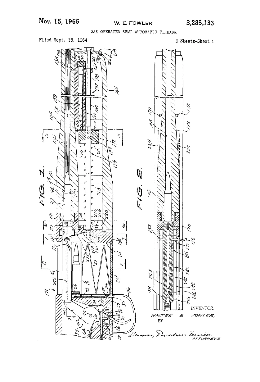
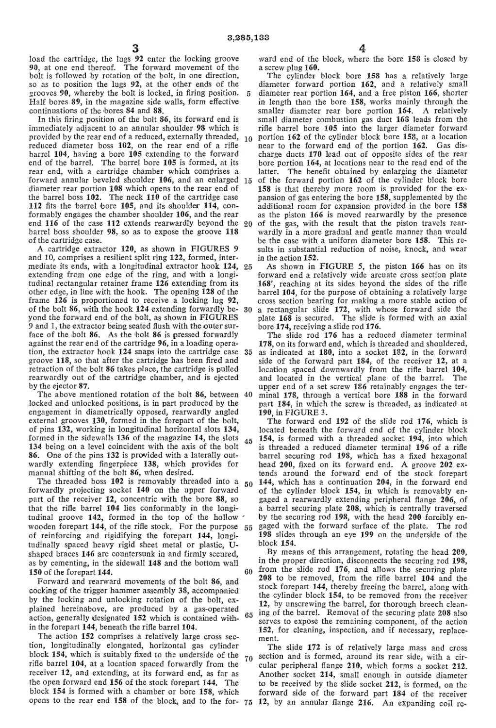
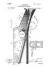
FIGURE 1 is a fragmentary and contracted vertical
longitudinal section taken through a rifle of the present
invention, showing the same cocked for firing;
FIGURE 2 is a horizontal section taken on the line
2—2 of FIGURE 1;
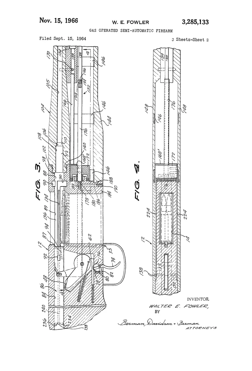
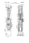
FIGURE 3 is a view substantially like FIGURE 1,
showing the components of the rifle following firing of
the rifle and preceding a loading operation;
FIGURE 4 is a' horizontal section taken on the line
4—4 of FIGURE 3;
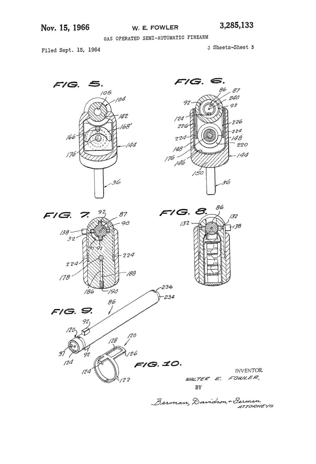
FIGURES 5 , 6, 7 and 8 are transverse vertical sec-
tions taken on the lines 5—5, 6—6, 7—7 and 8—8, re-
spectively, of FIGURE 1;
FIGURE 9 is an enlarged perspective view of the bolt
of the rifle, equipped with an extractor; and
FIGURE 10 is an enlarged perspective view of the
extractor, per se.
Referring in detail to the drawings, the illustrated rifle
comprises a receiver 12, formed with a vertical stagger
box cartridge magazine 14 formed with a loading and
extraction slot 16, at its upper end, and containing a
flat horizontal follower plate 18, which is biased up-
wardly by means of an accordion spring 20, compressed
between the follower plate and the floor 22 of the maga-
zine.
The follower plate 18 is formed, on its rear edge, with
a projection 24, which, at times, is adapted to engage
beneath a shoulder 26, on the upper part of a vertical
latch rod 28, which is positioned along the forward face
of the rear wall 30 of the magazine 14. At its lower
2
part, the latch rod 28 slides through the floor 22 of the
magazine 14, above which a coil spring 32 is circum-
posed on the rod, in a recess 34, and acts to bias the
rod downwardly, and thereby to extend its lower end
35 below the receiver 12, at a location behind the fore-
part of a trigger guard 36. This arrangement makes
possible and easy the manual raising of the latch rod
28 so that its upper end makes positive stop engage-
ment with the forward end of the bolt of the rifle, in
fully retracted position of the bolt, behind the maga-
zine 14, exemplified in FIGURE 3, so that the bolt can-
not be accidentally moved forwardly, by the trigger-
hammer assembly, and block loading of the magazine
or injure fingers of the user of the rifle, while loading a
15 single cartridge or a full load of cartridges, into the maga-
zine.
The trigger-hammer assembly 38, located within the
receiver 12, behind the magazine 14, comprises a ham-
mer 40, having a substantially circular body 42, axially
20 journaled, as indicated at 44, on the receiver, and having
a tangential, upwardly extending arm 46. The upper
part of the arm 46 is formed with a forwardly facing
beveled firing pin contacting nose 48. The lower part
of the hammer body 42 is formed with an arcuate ec-
25 centric edge 52, which terminates, at its rear end, in a
radial shoulder 54.
A horizontal longitudinal sear 56 works through a
bore 58 located on a level below the hammer 40, and
is biased rearwardly, by a contractile spring 60. The
30 sear has, on its forward end, an upstanding lug 62, which,
in the firing position of the assembly 38, engages the
eccentric edge 52 of the hammer, as shown in FIGURE
1, at a location forwardly of the pivotal axis of the ham-
mer 40. In the cocked position of the assembly 38, shown
35 in FIGURE 3, the lug 62 is engaged behind the shoul-
der 54 of the hammer 40, and holds the hammer in a
rearwardly tilted position, against the resistance of a
contractile spring 64, which is stretched between a rear-
ward part of the receiver 12 and a location 66, on the
40 hammer body 42, below and forward of the pivotal axis
of the hammer.
The trigger-hammer assembly 38 further comprises a
vertical trigger 68, which is pivoted, as indicated at 70,
across a recess 72, in the bottom of the receiver, through
45 which the finger-piece 74 of the trigger extends down-
wardly into the trigger guard 36. The trigger has a
V-shaped upper end 76 which is engaged in a V-shaped
notch 78 formed in the bottom of the sear 56. A verti-
cal spring 80 is compressed between the top of the recess
50 72 and the top of a rearwardly extending arm 82 on
the trigger, which aids the sear spring 64 in positioning
the sear rearwardly in the bore 58, and angling the trig-
ger finger-piece 74 upwardly and forwardly, in cocked
position, as shown in FIGURE 3.
55 The receiver 12 is formed, above the trigger-hammer
assembly 38, with a horizontal bore 84, which opens, at
its forward end, into the upper part of the magazine
14, the bore 84 being longer than a bolt 86 which it is
adapted to receive, as shown in FIGURE 3, in a re-
60 tracted position of the bolt. The bolt 86 has a spring-
pressed ejector 87 on its forward end.
The upper part of the receiver 12 forwardly of the
magazine 14, is formed with a bore 88, which is aligned
with the bore 84, and which, as shown in FIGURES 1,
65 3, 6 and 7, intermediate its ends, with opposed quarter
circular locking grooves 90, adapted to receive and re-
lease, at different times, a pair of diametrically opposed
lugs 92, located adjacent to the forward end 94 of the
bolt 86. When the bolt 86 has been move4 forwardly,
out of the receiver bore 84, and across the top of the
magazine, to receive a cartridge 96 from its magazine and
3,285,133
3
load the cartridge, the lugs 92 enter the locking groove
90, at one end thereof. The forward movement of the
bolt is followed by rotation of the bolt, in one direction,
so as to position the lugs 92, at the other ends of the
grooves 90, whereby the bolt is locked, in firing position.
Half bores 89, in the magazine side walls, form effective
continuations of the bores 84 and 88.
In this firing position of the bolt 86, its forward end is
immediately adjacent to .an annular shoulder 98 which is
provided by the rear end of a reduced, externally threaded,
reduced diameter boss 102, on the rear end of a rifle
barrel 104, having a bore 105 extending to the forward
end of the barrel. The barrel bore 105 is formed, .at its
rear end, with a cartridge chamber which comprises a
forward annular beveled shoulder 106, and an enlarged
diameter rear portion 108 which opens to the rear end of
the barrel boss 102. The neck 110 of the cartridge case
112 fits the barrel bore 105, and its shoulder 114, con-
formably engages the chamber shoulder 106, and the rear
end 116 of the case 112 extends rearwardly beyond the
barrel boss shoulder 98, so as to expose the groove 118
of the cartridge case.
A cartridge extractor 120, as shown in FIGURES 9
and 10, comprises a resilient split ring 122, formed, inter-
mediate its ends, with a longitudinal extractor hook 124,
extending from one edge of the ring, and with a longi-
tudinal rectangular retainer frame 126 extending from its
other edge, in line with the hook. The opening 128 of the
frame 126 is proportioned to receive a locking lug 92,
of the bolt 86, with the hook 124 extending forwardly be-
yond the forward end of the bolt, as shown in FIGURES
9 and 1, the extractor being seated flush with the outer sur-
face of the bolt 86. As the bolt 86 is pressed forwardly
against the rear end of the cartridge 96, in a loading opera-
tion, the extractor hook 124 snaps into the cartridge case
groove 118, so that after the cartridge has been fired and
retraction of the bolt 86 takes place, the cartridge is pulled
rearwardly out of the cartridge chamber, and is ejected
by the ejector 87.
The above mentioned rotation of the bolt 86, between
locked and unlocked positions, is in part produced by the
engagement in diametrically opposed, rearwardly angled
external grooves 130, formed in the forepart of the bolt,
of pins 132, working in longitudinal horizontal slots 134,
formed in the sidewalls 136 of the magazine 14, the slots
134 being on a level coincident with the axis of the bolt
86. One of the pins 132 is provided with a laterally out-
wardly extending fingerpiece 138, which provides for
manual shifting of the bolt 86, when desired.
The threaded boss 102 is removably threaded into a
forwardly projecting socket 140 on the upper forward
part of the receiver 12, concentric with the bore 88, so
that the rifle barrel 104 lies conformably in the longi-
tudinal groove 142, formed in the top of the hollow
wooden forepart 144, of the rifle stock. For the purpose
of reinforcing and rigidifying the forepart 144, longi-
tudinally spaced heavy rigid sheet metal or plastic, U-
shaped braces 146 are countersunk in and firmly secured,
as by cementing, in the sidewall 148 and the bottom wall
150 of the forepart 144.
Forward and rearward movements of the bolt 86, and
cocking of the trigger hammer assembly 38, accompanied
by the locking and unlocking rotation of the bolt, ex-
plained hereinabove, are produced by a gas-operated
action, generally designated 152 which is contained with-
in the forepart 144, beneath the rifle barrel 104.
The action 152 comprises a relatively large cross sec-
tion, longitudinally elongated, horizontal gas cylinder
block 154, which is suitably fixed to the underside of the
rifle barrel 104, at a location spaced forwardly from the
receiver 12, and extending, at its forward end, as far as
the open forward end 156 of the stock forepart 144. The
block 154 is formed with a chamber or bore 158, which
opens to the rear end 158 of the block, and to the for-
5
10
15
20
25
30
35
40
45
50
55
60
65
70
75
4
ward end of the block, where the bore 158 is closed by
a screw plug 160.
The cylinder block bore 158 has a relatively large
diameter forward portion 162, and a relatively small
diameter rear portion 164, and a free piston 166, shorter
in length than the bore 158, works mainly through the
smaller diameter rear bore portion 164. A relatively
small diameter combustion gas duct 168 leads from the
rifle barrel bore 105 into the larger diameter forward
portion 162 of the cylinder block bore 158, at a location
near to the forward end of the portion 162. Gas dis-
charge ducts 170 lead out of opposite sides of the rear
bore portion 164, at locations near to the read end of the
latter. The benefit obtained by enlarging the diameter
of the forward portion 162 of the cylinder block bore
158 is that thereby more room is provided for the ex-
pansion of gas entering the bore 158, supplemented by the
additional room for expansion provided in the bore 158
as the piston 166 is moved rearwardly by the presence
of the gas, with the result that the piston travels rear-
wardly in a more gradual and gentle manner than would
be the case with a uniform diameter bore 158. This re-
sults in substantial reduction of noise, knock, and wear
in the action 152.
As shown in FIGURE 5, the piston 166 has on its
forward end a relatively wide arcuate cross section plate
168', reaching at its sides beyond the sides of the rifle
barrel 104, for the purpose of obtaining a relatively large
cross section bearing for making a more stable action of
a rectangular slide 172, with whose forward side the
plate 168 is secured. The slide is formed with an axial
bore 174, receiving a slide rod 176.
The slide rod 176 has a reduced diameter terminal
178, on its forward end, which is threaded and shouldered,
as indicated at 180, into a socket 182, in the forward
side of the forward part 184, of the receiver 12, at a
location spaced downwardly from the rifle barrel 104,
and located in the vertical plane of the barrel. The
upper end of a set screw 186 retainably engages the ter-
minal 178, through a vertical bore 188 in the forward
part 184, in which the screw is threaded, as indicated at
190, in FIGURE 3.
The forward end 192 of the slide rod 176, which is
located beneath the forward end of the cylinder block
154, is formed with a threaded socket 194, into which
is threaded a reduced diameter terminal 196 of a rifle
barrel securing rod 198, which has a fixed hexagonal
head 200, fixed on its forward end. A groove 202 ex-
tends around the forward end of the stock forepart
144, which has a continuation 204, in the forward end
of the cylinder block 154, in which is removably en-
gaged a rearwardly extending peripheral flange 206, of
a barrel securing plate 208, which is centrally traversed
by the securing rod 198, with the head 200 forcibly en-
gaged with the forward surface of the plate. The rod
198 slides through an eye 199 on the underside of the
block 154.
By means of this arrangement, rotating the head 209,
in the proper direction, disconnects the securing rod 198,
from the slide rod 176, and allows the securing plate
208 to be removed, from the rifle barrel 104 and the
stock forepart 144, thereby freeing the barrel, along with
the cylinder block 154, to be removed from the receiver
12, by unscrewing the barrel, for thorough breech clean-
ing of the barrel. Removal of the securing plate 208 also
serves to expose the remaining component, of the action
152, for cleaning, inspection, and if necessary, replace-
ment.
The slide 172 is of relatively large mass and cross
section and is formed, around its rear side, with a cir-
cular peripheral flange 210, which forms a socket 212.
Another socket 214, small enough in outside diameter
to be received by the slide socket 212, is formed, on the
forward side of the forward part 184 of the receiver
12, by an annular flange 216. An expanding coil re-
3,285,133
5
turn spring 218 is circumposed on the slide rod 176
and is compressed between the bottoms of the sockets
212 and 214. The spring 218 serves not only to cushion
the rearward travel of the slide 172, as the rifle is fired,
but to return the slide to its normal forward position,
against the rear end of the cylinder block 154 and to
return the piston 166 forwardly, after a drive stroke.
A flat coil buffer spring 220 is secured around the
annular flange 216, of the socket 214, which is adapted
to be engaged by the flange 210 of the slide 172, to-
ward the end of the rearward travel of the slide, whereby
the shock, noise, and jar, which would otherwise occur
as a result of forcible contact of the slide 172 with the
receiver 12 are eliminated.
Cross pins 222 serve to fix securely to one side of
the slide 172, the rear end of one of two flat horizontal
longitudinal action bars 224, which are adapted to move
endwise in vertical slots 226, defined between the inner
surfaces of the stock forepart sidewalls 148, and the
related sides of the receiver 12, as shown in FIGURES
6, 7 and 8. The other action bar 224 is preferably inte-
gral with the related side of the slide 172. The action
bars 224 terminate, at their rear ends, in upstanding
right-triangular wings 228, having rearwardly and up-
wardly angled forward edges 230, which, as shown in
FIGURE 1, are adapted to engage conformably angled
top surfaces 232, formed on the forward part of the re-
ceiver, in the forward positions of the action bars. At
their upper ends, the action bar wings 228 are operatively
connected to the pins 132 which are engaged in the
bolt rotating grooves 130, so that, as the slide 172 is
moved rearwardly and forwardly, the bolt 86 is moved
in corresponding directions, and rotated.
A safety feature concerning the bolt 86, involves form-
ing the rear end of the bolt 86 with a substantially hemi-
spherical cam surface 234, traversed by a normally ver-
tical groove 236, in which the rear end 238, of a firing
pin 240, is exposed, to be struck by the nose 48 of the
hammer 40, when the trigger piece 74 is pulled. The
groove 236 normally conformably receives the nose 48
of the hammer, but should the bolt 86 not be com-
pletely “home,” in its forward position, due to an in-
complete rotation of the bolt, the groove 236 will be
canted, relative to the nose 48 of the hammer, so that,
if the trigger be pulled, the nose cannot enter the groove
236 and drive the firing pin, but instead, engages the
cam surface 234. This positively prevents disastrous fir-
ing or a chambered cartridge with the bolt not fully
forward and locked. The firing pin 140 works in an
axial bore 242, extending through the bolt 86, and is
retained therein, and limited in movement, by the en-
gagement of the tip 244 of a radial screw 246, in a
longitudinal groove 248, in the side of the firing pin, as
shown in FIGURE 2.
What is claimed is:
1. The combination of a firearm receiver, a barrel ex-
tending forwardly from the receiver, said receiver being
formed with bore means aligned with the barrel, the barrel
being formed with a bore including a cartridge chamber,
a cartridge detonating bolt movable endwise in the receiver
bore means, a cylinder block secured to the underside of
the barrel and spaced forwardly from the receiver, said
block being formed with a rearwardly-opening bore con-
taining an endwise movable piston, means providing com-
munication between the barrel bore and the block bore in
front of the piston, gas-discharge duct means leading
from the block bore adjacent to the rear end thereof,
and means operatively-connecting the piston to the bolt,
said connecting means comprising a slide bar affixed to
and extending forwardly from the receiver, a slide cir-
cumposed on the slide bar and having a forward side
adapted to be movably-engaged by the rear end of the
piston, return-spring means compressed between the slide
and the receiver, said block bore and the piston being of
10
15
20
25
30
35
40
45
50
55
60
65
70
75
6
arcuate transverse cross section and relatively wide as
compared to the slide bar.
2. A firearm comprising a receiver formed intermediate
its ends with an upwardly-opening magazine, an upwardly
spring-pressed cartridge follower in the magazine, said re-
ceiver having a rear part and a forward part, said rear
part being hollow, a spring-pressed trigger hammer as-
sembly mounted within said rear part of the receiver and
having a trigger finger piece extending downwardly below
said rear part, said assembly having an upstanding ham-
mer formed with a forwardly-facing nose, said rear part
of the receiver being formed with a rear horizontal bore
overlying said assembly and opening at its forward end to
the magazine, said forward part of the receiver being
formed with a forward bore aligned with the rear bore,
a bolt longer in length than the distance between the fac-
ing ends of said bores and adapted to bridge this distance
when engaged in the forward bore in projected firing posi-
tion, a barrel secured to and extending forwardly from
the forward part of the receiver, said barrel having a bore
smaller in diameter than and axially-aligned with said for-
ward bore, the rear end of the barrel bore being formed
with a shoulder cartridge chamber, said bolt having a lon-
gitudinally-movable firing pin having forward and rear
ends, the rear end of the firing pin being adapted to be
struck by the nose of the hammer as the result of pulling
the trigger finger piece for firing a cartridge present in
the cartridge chamber, a vertical downwardly spring-
pressed safety bolt latch mounted at the rear end of the
magazine and has a lower end exposed below the receiver
in front of the trigger fingerpiece, said latch having a for-
wardly projecting shoulder at its upper end and said fol-
lower plate having a projection on its rear end adapted
to engage beneath the shoulder, the lower end of the latch
being adapted to be manually engaged and elevated to put
an upper part of the latch in stop engagement with the
forward end of the bolt in a retracted position of the bolt.
3. In combination, a firearm comprising a receiver, an
open top magazine located intermediate the ends of the
receiver and containing an upwardly spring-pressed fol-
lower plate, said magazine dividing the receiver into for-
ward and rear parts, a gun barrel secured at its rear end
to the forward part of the receiver and extending for-
wardly therefrom, said barrel being formed with a cham-
bered bore, said forward and rear parts of the receiver
being formed with aligned forward and rear bores which
are aligned with the barrel bore, a bolt working in the
receiver bores and adapted to be positioned in the rear
bore in the retracted position of the bolt with its for-
ward end at the rear end of the magazine, said bolt hav-
ing a longitudinal-movable firing pin, a spring-pressed trig-
ger hammer assembly on the rear part of the receiver,
said assembly having a hammer formed with a nose
adapted to strike the rear end of the firing pin for detonat-
ing a cartridge present in the chamber of the barrel bore,
with the bolt in a forwardly-projected position, a hollow
stock forepart beneath the barrel and extending forward-
ly from the forward part of the receiver, and a combus-
tion gas-operated action enclosed within the stock fore-
part, said action comprising a cylinder block fixed to the
underside of the barrel, said block being formed with a
bore opening to the rear end of the block and closed at
its forward end, a piston working in the block bore, a gas
duct providing communication between the barrel bore
and the block bore forwardly of the piston, gas-exhaust
duct means leading out of the block bore at a location
intermediate the ends thereof, drive means operatively-
connecting the piston to the bolt for moving the bolt rear-
wardly to a retracted position as the cartridge present in
the barrel bore chamber is detonated, and spring-return
means for returning said drive means and the bolt to for-
wardly-projected position, said stock forepart having an
open forward end, said forward end being formed with
a peripheral groove, the cylinder block having a forward
end formed with a groove in continuation of the forepart
3,285,133
7
groove, a securing plate having a rearwardly extending
peripheral flange engaged in the forepart groove and the
cylinder block groove, and a securing rod sliding through
the securing plate and separably secured at its rear end to
the forward end of the slide rod, and an enlarged head on
the forward end of the securing rod bearing against the
forward side of the securing plate.
4. A firearm comprising a receiver, an open-top maga-
zine located intermediate the ends of said receiver and
dividing the receiver into forward and rear parts, a gun
barrel secured at its rear end to the forward part of the
receiver and extending forwardly therefrom, said barrel
being formed with a chambered bore, said forward and
rear parts of the receiver being formed with aligned for-
ward and rear bores which are aligned with the barrel
bore, a bolt working in the receiver bores and adapted to
be positioned in the rear bore in the retracted position of
the bolt with its forward end at the rear end of the maga-
zine, a hollow stock forepart provided with a closed end
disposed beneath the barrel and extending forwardly from
the forward part of the receiver, said stock including an
elongated cylindrical block provided with a bore extend-
ing axially therethrough and having an elongated piston
working in said bore, and a combustion gas-operated
action arranged within said stock in cooperative relation
with respect to said cylinder block, there being a gas duct
providing communication between the barrel bore and the
block bore forwardly of the piston, gas-exhaust duct
means leading out of the block bore at a location be-
tween the ends of the piston, said action embodying a
slide rod extending longitudinally ofsaid stock forepart
and located beneath said cylindrical block and having one
end fixedly-supported in the closed end of said forepart
stock and having the other end fixedly-supported in the
forward part of the receiver, a slide slidable on the slide
rod and freely-engaging the adjacent end of said piston,
and means operatively-connecting said slide to said bolt
for retractile movement of said bolt responsive to the
backward movement of said piston.
5. The firearm according to claim 4 which includes
in addition spring means operatively-connected to said
slide and said slide rod and serving to cause simultaneous
5
10
15
20
25
30
35
40
8
projectile movement of said bolt and forward movement
of said piston.
6. The firearm according to claim 5 which includes in
addition buffer spring means operatively-connected to the
forepart of said receiver and serving to counteract the
shock upon impact of said slide with the forepart of said
receiver when the bolt has executed its retractile move-
ment.
7. The firearm according to claim 4 wherein said means
comprises a part of flat horizontal longitudinal action bars
having one of the complemental ends operatively-con-
nected to said slide, and a pair of upstanding wings located
adjacent to and attached to the other of the complemental
ends of said action bar, said wings being operatively-con-
nected to a pair of pins riding in arcuate slots formed in
said bolt.
8. The firearm according to claim 4 wherein said
block bore includes a rear bore portion and a forward
bore portion w'hich is of larger diameter than the rear
bore portion, and wherein said piston works mainly
through the smaller diameter rear bore portion.
References Cited by the Examiner
UNITED STATES PATENTS
A.1.157 12/1856 Newton___________________42—20
853,715 5/1907 Mondragon________________42—22
2,394,986 2/1946 Crockett_________________89—193
2,582,989 1/1952 Harvey___________________89—193
2,932,108 4/1960 Hughel et al.____________89—185
3,009,396 11/1961 Dixon____________________89—191
3,058,399 10/1962 Allyn____________________89—191
3,137,084 6/1964 Reed______________________42—25
3,161,978 12/1964 O’Brien et al_____________42—25
FOREIGN PATENTS
652,962 5/1951 Great Britain.
321,532 10/1934 Italy.
SAMUEL FEINBERG, Primary Examiner.
FRED C. MATTERN, Jr., Examiner.
S. C. BENTLEY, Assistant Examiner.