/


Tags: weapons military affairs patent
Year: 1907

Text
No. 870,719.
PATENTED NOV. 12, 1907.
C. FREEMAN.
AUTOMATIC FIREARM.
APPLICATION TILED AUG. 17. 1905.
3 SHEETS-SHEET 1,
No. 870,719.
PATENTED NOV. 12, 1907.
0. FREEMAN.
AUTOMATIC FIREARM.
APPLICATION PILED AUG. 17, 1905.
3-SHEETS-SHEET 2.
No. 870,719.
PATENTED NOV. 12, 1907.
0. FREEMAN.
AUTOMATIC FIREARM.
APPLICATION TILED AUG. 17, 1905.
3 SHEETS—SHEET 3.
UNITED STATES PATENT OFFICE
CHARLES FREEMAN, OF LOS ANGELES, CALIFORNIA.
AUTOMATIC FIREARM.
No. 870,719. Specification of Letters Patent. Patented Nov. 12, 1907.
Application filed August 17,1905. Serial Ko. 274,522.
5
10
15
20
25
30
35
40
45
50
55
To all whom it may concern:
Be it known that I, Charles Freeman, a citizen of
the United States, residing at Los Angeles, in the
county of Los Angeles and State of California, have in-
vented a new and useful Automatic Firearm, of which
the following is a specification.
This invention relates to automatic fire-arms of the
type shown and described in a former application of
mine, filed August 15, 1904, Serial Number 220,740,
embodying a new principle in automatic fire arms
which consists in allowing a device such, for instance,
as the breech-bolt, a short backward primary move-
ment upon the discharge of the arm, this movement
being stopped by a suitable locking means; the great
bulk of the backward-thrust from the explosion in the
barrel being solidly opposed by this locking means to
the breech-bolt; meanwhile a momentum-Ыбск which,
while the parts are in their closed and locked position,
is in intimate contact with the breech-block (which,
in fact, it holds in its forward position through pressure
exerted by a reaction spring) receives impulse from the
short primary movement of the breech-block the mo-
mentum thus imparted to the momentum-block being
sufficient to reciprocate it along the frame, unlock the
breech-bolt, pull it back from the breech, compress a
reaction spring and operate the arm, the pressure of the
reaction spring then reverses the movement of the mo-
mentum-block which then operates to close the breech
and leave the arm in its normal closed position.
The main object of the present invention is to im-
prove the construction of this type of automatic fire
arms throughout the mechanism to secure compact-
ness, strength, durability and easy action.
A further object is to provide an improved trigger
mechanism.
Another object is to provide means for protecting the
external manual - operating device against accidental
interference.
The accompanying drawings illustrate the invention,
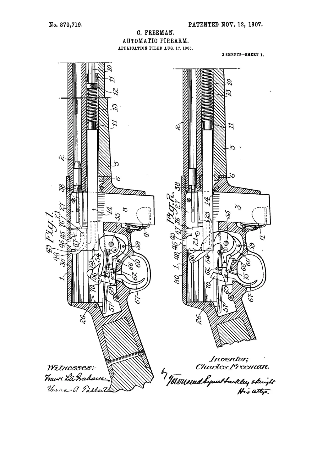
and referring thereto:—Figure 1 is a vertical longitu-
dinal section through the breech of the fire-arm, show-
ing the parts in the position which they have before the
trigger is pulled. Fig. 2 is a similar view, showing the
position of the parts immediately after the discharge,
the breech-bolt and momentum-block having been
moved back a slight distance to the point at which the
backward movement of the breech-bolt is stopped by
the, locking-block. Fig. 3 is a similar view, showing
the next position of the parts in which the momentum-
block has moved farther back and has tilted the lock-
ing-block and unlocked the latter from the frame.
Fig. 4 is a similar view, showing the next position of the
parts in which the momentum-block has moved to the
extreme rearward limit of its stroke, cocked the ham-
, mer and retracted the breech-bolt, the shell having
been ejected and a fresh cartridge being shown spring-
ing into place. Fig. 5 is a side elevation of the fire-arm,
part of the stock being broken away and illustrates one
form of guard for protecting the stem of the momentum-
block. Fig. 6 is a side elevation of the forward end of 8©
the barrel and fore-stock, and illustrates a modified
form of guard which protects the stem of the momen- ’
tum-block. Fig. 7 is a longitudinal vertical section
taking diametrically through the breech-bolt locking-
block and adjacent parts of the frame, showing the 85 ,
Airing-pin in elevation, the locking-block being in
locked position. Fig. 8 is a perspective view, showing
in detail the hammer and sear. Fig. 9 is a perspective
view, showing in detail the trigger and sear operating
device. Fig. 10 is a front elevation showing in detail 70
the sear operating device detached from the trigger.
Fig. 11 is a perspective view showing the trigger only.
Fig. 12 is a perspective view showing in detail the
breech-bolt. Fig. 13 is a perspective view showing in
detail the locking-block. Fig. 14 is a perspective view 7 5
showing in detail the firing-pin. Fig. 15 is a perspec-
tive view showing in detail the momentum-block, part
of its stem being broken away.
1, designates the frame to which is rigidly attached
the barrel 2. The lower part of the frame 1 is cham- 80
bered to receive a magazine 3 which may be of the
common box magazine type as shown and detachably
held in place by a spring controlled detent 4. The
fore-stock 5 projects forward from the frame 1 under-
neath the barrel 2, its rear end being held in place by 85
a toe 6 which engages the frame 1 while its forward end
is retained by straps 7 which are united by a guard 8,
the fore-stock 5 being cut away to form a slot 9, into .
which projects the end of the stem 10 of a momentum-
block about to be described. The slot 9 allows the 90
stem 10 to be manually retracted when desired, and
as the stem 10 lies in the slot 9 and is protected by the -
guard 8 and walls of the slot, its accidental operation is
prevented.
As shown in Fig. 1, guides 11 which depend from the 9®
barrel 2, serve to guide the momentum-block stem 10.
A collar 12 is fastened to the stem 10 and a reaction-
spring 13 is interposed between the collar 12 and the
rear guide 11, and the reaction-spring 13 operates to
actuate the momentum-block stem 10 forward together 10©
with its connected parts, as will be hereinafter de-
scribed. As shown in Fig. 15, the rear end of the mo-
mentuni-block stem 10 is joined to a bifurcated mem-
ber 14 having legs 15 and 16 which are respectively
provided at their rear ends with raised lugs 17 and 18, 10®
each of which has shoulders 19 and 20. The lug 18 is
provided with an inwardly projecting pin 21. The
lug 17 is provided with an inclined slot 22, enlarged at
its upper end and formed with a shoulder 23. Project-
ing inwardly from the rear end of the leg 16 and from 110
the lug 18 is a boss 24, having a rounded shoulder 25.
The bifurcated member 14, stem 10, together with the-
870,716
5
10
15
20
25
30
35
40
45
50
55
60
65
lugs 17 and 18, form what will be termed a momentum-
block. The legs 15 and 16 are slidably mounted in
grooves or ways 26 formed inrthe side walls of the frame
1, as shown in Figs. 1, 2 and 3.
Slidably mounted in the frame 1, directly back of
the barrel 2, is a breech-bolt 27, shown in detail in Fig.
12, being provided with a longitudinal recess 28 and
with grooves 29 on one side. The upper wall of the
frame 1 has a downwardly projecting rib 30 which pro-
jects slightly into the recess 28 and serves to strengthen
the top wall of the frame 1 and also to guide the breech-
bolt. As shown in Fig. 4, an ejector 31 is arranged on
the frame over which the groove 29 of the breech-bolt
slides. The left side of the frame is provided with a
longitudinal rib 32 and with a corner rib (not seen),
over which the grooves 29 in the breech-bolt 27 slidably
fit. The extreme forward nose 33 of the breech-bolt
is centrally perforated at 34 and is counterbored to
form a recess 35 adjoining the perforation 34. One
side of the breech-bolt is provided with claws 36 against
which the rim of the cartridge rests, while the other
side of the breech-bolt is provided with a spring re-
tractor hook 38 which engages the rim of the shell to
carry the same back with the breech-bolt until the shell
is ejected. The rear end of the breech-bolt has abut-
ments 39, which act against the shoulders 20 of the
momentum-block to impart movement to the momen-
tum-block when the fire-arm is discharged, as will be,
hereinafter described. The rear end of the breech-bolt
27 is also provided with abutments 40.
Mounted in the recess 28 of the breech-bolt is a lock-
ing-block 41, the latter being pivoted to swing verti-
cally in the recess 28 by means of a pin 42 which is
fixed in the breech-bolt 27 at the perforations 43, and
the locking-block 40 is provided with an elongated slot
44 which allows a slight longitudinal movement of the
breech-bolt relatively to the locking-block. The lock-
ing-block near its rear end is provided with an upwardly'
projecting lug 45, which is adapted to engage in a lock-
ing-notch 46 formed in the upper wall of the frame 1.
(See Figs. 1, 2, 3 and 7). The locking-block 41 is pro-
vided with a pair of side lugs 47, against which the
abutments 40 of the breech-bolt strike and serve to stop
the backward movement of the breech-bolt when the
locking-block is in locked position, engaging the notch
in the frame. The locking-block 41 is provided with
a wing 48 having a tortuous slot 49, and the wing 48 lies
between the lugs 17 and 18 of the momentum-block,
while the pin 21 of the latter projects into the slot 49.
The locking-block 41 near its lower edge is bored
longitudinally to receive the stem of a firing-pin 50,
as shown in Fig. 7. The rear end of the firing-pin 50
has a flattened shank 51 with a laterally extending
stud 52, which projects into the slot 22 in the lug 17 of
the momentum-block. The forward end of the firing-
pin 50 extends into the recess 35 of the breech-bolt
and into the perforation 34 when in normal position,
as shown in Fig. 7. The forward end of the locking-
block 41 has a projection 53 which strikes against a
shoulder-53“ on the frame to limit the forward move-
ment of the locking-block.
54 designates the hammer which is pivoted at 55 to
the frame, and is provided with an off-set lug 56,
against which the rounded abutment 25 of the momen-
tum-block strikes when the momentum-block moves
back, and as the latter continues toward the rear end
of its stroke, the abutment 25 rides over the lug 56 and
throws back the hammer.
57 designates the main-spring which acts upon the
stirrup 58 to throw the hammer forward when it is re- 7 0
leased. Pivoted at 59 below the hammer is a sear 60
which is adapted to normally engage the cocking-notch
61 of the hammer. The rear end of the sear 60 is pro-
vided with an arm 62 having a rfearwardly extending
lip 63 and with a shoulder 64, against which a sear 75
spring 65 presses, as shown in Fig. 8.
Pivoted at 66 is a trigger 67, and pivotally mounted
at 68 on the trigger 67 is a sear-operating device 69
comprising an arm 70 and a finger 71 which is adapted
to coact with the arm 62 to operate the sear, as will 80
hereinafter be described. A flat spring 73 presses
against the off-set shoulder 74 of the arm 70 and serves
to normally hold the arm 70 against a stop pin 75, which
projects laterally from the trigger 67, to yieldingly hold
the trigger in normal position. 85
The operation of the trigger mechanism will first be
described.
The hammer 54 is pushed back by the backward
movement of the momentum-block 14 through the me-
dium of its rounded abutment 25 which presses against 90
the lug 56 on-the hammer. The first cartridge is in-
serted by manually retracting the momentum-block by
pressing back the stem 10 and then releasing it, and
the subsequent operation of the fire-arm is performed
automatically as will be described. 95
Fig. 3 shows the hammer being pressed back by the
rounded abutment 25, and it will be observed that the
linger 71 of the sear operating device stands under the
lip 63 of the sear arm 62. This is due to tire trigger be-
ing manually held back, for the hammer is swung back 100
automatically-after the discharge of the fire-arm with
great rapidity before the trigger can bo released. As
the momentum-block continues further back, the rear
end of its leg 16 strikes the arm 70 and tilts the sear
operating device, as shown.in Fig. 4, so that the finger 105
71 is retracted from under the lip 63 of the sear arm,
whereupon the sear 60 becomes operative so that it en-
gages the cocking notch 61 of the hammer. If the fin-
ger 71 of the sear operating device was not moved back
from under the lip 63, the sear would be held out of 110
engagement with the cocking notch and the hammer
would not be caught by the sear. As soon as the sear
engages the cocking notch, and when the momentum-
block moves forward and releases the arm 70. the spring
73 tilts the sear operating device upon its pivot 68 until 115
it is stopped by the finger 71-striking against the edge
of the lip 63, and as soon as the trigger is released it
carries down the-sear operating device bodily, and so
that when the finger 71 clears the lower edge of the lip
63, the spring 73 snaps the sear operating device into 120
normal position in which the lip 63 stands over, the
finger 71 -ready to be operated thereby upon the up-
ward movement of the finger 71 when the trigger is
again pulled, thus the sear is always in condition to
engage the hammer when it is cocked until the trigger 125
is released and again pulled so that the hammer is ah
ways cocked upon the backward movement of the mo-
mentum-block even before the trigger has been re-
leased.
The fire-arm is ready to be discharged when the 130
870,710
a
parts stand in the position shown in Fig. 1. It will be
noted that the locking-block 41 is locked with the frame,
that the breech-bolt is in extreme forward position
abutting against the rear end of 'the barrel and leaving
5 a slight space 76 between the abutments 40 of the
breech-bolt 27, and the lugs 47 of the locking-block 41;
the momentum-block is also in extreme forward posi-
tion with its shoulders 20 lying in contact with the
abutments 39 of the breech-bolt, and its shoulder 19
10 lying under the lugs 47 of the locking-block 41 so that
the latter is supported in locked position. The pin
21 of the momentum-block is in the forward horizontal
portion of the slot 49 of the locking-block; the firing pin
is in normal position with its end slightly back of the
15 cartridge, the stud 52 of the firing pin being in the up-
per and rear end of the slot 22 of the momentum-block.
Upon pulling the trigger the hammer is released and
strikes the rear end of the firing pin 50 which is driven
forward slightly and explodes the cartridge. The re-
20 coil drives back the breech-bolt and momentum-block
together, but as soon as the breech-bolt has moved back
the distance allowed by the slight space 76, it is stqpped
by the locking-block, the abutment 40 of the breech-
bolt strikes the lugs 47 of the locking-block, the parts
25 now being in the position shown in Fig. 2 in which it
will be seen that the space 76 is closed. The mbmen-
tum-block thus receives a definite amount of energy
from this short movement of the breech-bolt and con-
tinues moving back after the breech-bolt has been
30 stopped, and the shoulder 23 on the lug 17 of the mo-
mentum-blockacting against the stud 52 retracts the
firing pin so that the front end of the latter lies within
the enlarged recess 35 of the breech-bolt. During this
short partof the travel of the momentum-block, its pin
35 21 traverses the longitudinal portion of the slot 49, and
the locking-block 41 remains locked with the frame,
but the further backward movement of the momentum-
block causes its pin 21 to ride along the inclined rear
portion of the slot 49 which results in swinging down
40 the locking-block 41 on its pivot and unlocking it from
the frame, the locking-block in swinging down carries
the firing pin bodily with it, but as the front end of the
firing pin has already been retracted from the orifice
34, its forward end swings freely in the enlarged recess
45 35. The parts now stand as shown in Fig. 3. As the'
momentum-block continues moving back from this
position it pulls the locking-block with it, and the
locking-block pulls along the breech-block so that these
three parts including the firing pin move back together
50 to the position shown in Fig. 4. During this move-
ment the fired shell in the grasp of the extractor is
pulled back with the breech-bolt and strikes the ejec-
tor 31 and is ejected through the side of the frame in the
well known manner, and’ a fresh cartridge from the
5 5 magazine springs up in front of the breech-bolt as shown
in Fig, 4.
During the operation of the parts above described,
the reaction spring has been compressed by the back-
ward movement of the momentum-block and at the
60 termination of the rear stroke of the latter, the reaction
spring expands and draws the momentum-block for-
ward and the momentum-block pushes forward the
locking-block and the breech-bolt which is linked with
the latter. When the front projection 53 of the lock-
6 5 ing-block strikes the front part of the frame it is stopped,
and as the momentum-block moves still further forward
into its normal position, its pin 21 riding forward in the
slot 49 swings up the locking-block and throws the lug
45 of the latter into the notch 46 in the frame, and the
shoulders 19 slide under the lugs 47; at the same time 7 0
the firing pin is pushed forward into normal position,
its stud 52 being acted upon by the rear inclined wall
of the slot 22. Towards the conclusion of the forward
movement of the momentum-block, it brings the breech-
bolt into its extreme forward position with its rear abut- 7 5
ments 39 in intimate contact with the shoulders 20 of
the momentum-block, leaving the slight space 76 be-
tween the abutments 40 of the breech-bolt and the lugs
47 of the locking-block, and as the hammer has been
left cocked, as previously described, the arm is ready 80
to be fired.
Experience has shown that the space 76 between the
abutments 40 of the breech-block'and the lugs 47 of the
locking-block need not be greater than 1/32 of an inch
to cause the desired amount of energy to be transmitted 8 5
to the momentum-block.
What I claim is:—
1. In. an automatic fire-arm a frame, a breech-bolt slid-
ably mounted on said frame and being recessed for the
greater part of Its length, a locking-block pivoted therein gg
and having a vertical locking moVenient against the frame,
a firing pin mounted In said lockliig-block and extending
forwardly through the breech-bolt, a momentum-block co-
aeting with said firing pin to withdraw it from contact
with the breech-block, before the unlocking movement be- 95
gins.
2. In an automatic fire-arm, a frame, a hammer pivoted
m said frame, a sear plvqted in said frame, a trigger
mounted in said frame, a member pivoted on said trigger
to engage the rear end of the sear when the parts are In Ю0
their normal closed position, and means for cocking the
hammer arid throwing the pivoted member out of engage-
ment with the sear.
3: In an automatic fire-arm, a frame, a hammer mounted
in said frame, a sear pivoted in said frame, a trigger, a 105
member pivoted on said trigger so as to engage tile rear
end of the sear when the parts are In their normal closed
position, a reciprocating momentum-block mounted In the
frame, contacting with the hammer to cock the same and
with the pivoted member upon the trigger to throw the Ц0
trigger out of engagement with the sear.
4. In nn automatic fire-arm, к frame, a hammer mounted
in said frame, a sear pivoted in said frame, a trigger, a
member pivoted on said trigger so as to engage the rear
end of the sear when the parts are In their normal closed
position, a reciprocating momentum-block mounted In the
frnnie contacting with the hammer to cock the same and
witli the pivoted member upon the trigger to throw the
trigger out of engagement with the sear, and Intermediate
means between a cartridge in the barrel and the momen- |20
tnm-block whereby a limited amount of the total energy
derived by the explosion Is imparted to the momentum-
block.
5. In an automatic fire-arm, a breech-bolt recessed longi-
tudinally, a locking-block In said recess and provided with 125
lugs for coactlng with an abutment on the breech-bolt for
stopping the latter when the locking-block is in locked posi-
tion, and a firing pin carried bodily by the locking-block.
6. In an automatic fire-arm, a breech-bolt, a 1c .’king-
block engaging the breech-bolt and controlling the opera- J30
tlon of the breech-bolt, a firing pin carried by the locking-
block, the forward end of the breech-bolt being perforated
to receive the end of the firing pin, and means for retract-
ing the firing pin in tile locking-block before the locking-
block is unlocked. 135
7. In a Il re-arm, a breech-bolt recessed the greater por-
tion of, Its length, a locking-block lying in said recess and
mounted to swing in a vertical plane, a firing pin carried
by the locking-block, the forward end of the breech-bolt
having a perforation for receiving the end of the firing 140
4
870,719
pin, and means for retracting the firing pin free from the
perforation before the locking-block is swung down from
its locked position.
8. In an automatic fire-arm, a frame, a barrel fixed on
5 the frame, a breech bolt slidably mounted on said frame
and being recessed for the greater part of Its length, a
locking block pivoted therein and having a vertical locking
movement against the frame, a firing pin mounted in said
locking block and extending forwardly through the breech
10 bolt, a momentum block coacting with said firing pin to
withdraw it from contact with the breech block before the
unlocking movement begins, the momentum block extend-
ing forward under the barrel, and means mounted on the
barrel for slidably engaging the forward end of the mo-
15 mentum block and keeping it in alinement with the frame.
9. In an automatic fire arm, a frame, a barrel on said
frame, a hammer mounted in said frame, a sear pivoted in
said frame, a trigger, a member pivoted on said trigger so
as to engage the rear end of the sear when the parts are
in their normal closed position, a reciprocating momentum 20
block mounted in the frame contacting with the hammer
to cock the same and with the pivoted member upon the
trigger to throw the trigger out of engagement with the
sear, intermediate means between a cartridge in the barrel
and the momentum block whereby a limited amount of the 25
total energy derived by the explosion is imparted to the
momentum block, the momentum block having a forward
extension, an operating spring mounted upon said exten-
sion, and means mounted on the barrel for slidably engag-
ing the forward end of the momentum block. 30
In testimony whereof, I have hereunto set my hand at
Los Angeles California this. 10th day of August 1905.
CHARLES FREEMAN.
In presence of—
Geobge T. Hackley,
Vebna A. Talbebt.