/
Tags: weapons military affairs patent
Year: 1961
Text
Nov. 21, 1961 p. h. dixon 3,009,396
GAS PISTON OPERATED AUTOMATIC GUN
Filed Sept. 24, 1947 ~ ,
l Sneets-Sheet 1
Iri ventor
Paul H Diuron
by hys AjDyieiJ
Nov. 21, 1961
P. H. DIXON
3,009,396
GAS PISTON OPERATED AUTOMATIC GUN
Filed Sept. 24, 1947
7 Sheets-Sheet 2
Inventor
Paul HDijron
Nov. 21, 1961 p. н, DIXON 3,009,396
GAS PISTON OPERATED AUTOMATIC GUN
Filed Sept. 24. 1947 7 Sheets-Sheet 3
Z9Z. Я? S%7
Nov. 21, 1961 p. н. dixon 3,009,396
GAS PISTON OPERATED AUTOMATIC GUN
Filed Sept. 24. 1947 7 Sheets-Sheet 4
3,009,396
Nov. 21, 1961
P. H. DIXON
GAS PISTON OPERATED AUTOMATIC GUN
Filed Sept. 24, 1947
7 Sheets-Sheet 5
Paul H.Dlocon
Nov. 21, 1961 p. н. dixon 3,009,396
GAS PISTON OPERATED AUTOMATIC GUN
Filed Sept. 24, 1947 7 Sheets-Sheet 7
3,009,396
Patented Nov. 21, 1961
United States Patent Office
2
through mechanism hereinafter described, to the cradle,
and a recoil spring nut 48 (FIG. 3) which is threaded
onto a barrel 50 of the gun and may be considered as
part of the barrel.
The barrel 50 is threaded into a receiver 52 and is
properly positioned lengthwise in and secured to the re-
ceiver by a screw 54 (FIGS. 2, 4 and 5) which is thread-
ed into the receiver and fits in a recess 56 in the barrel.
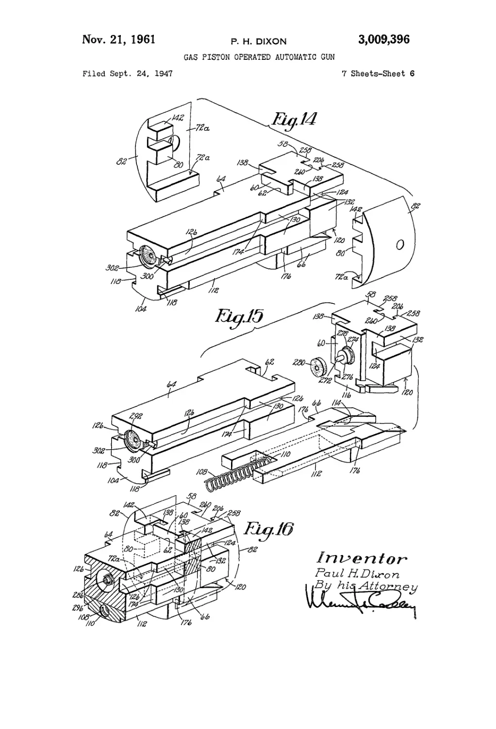
The gun is provided with a breechblock or a bolt 58
having a rear T-shaped tongue or projection 60 (FIGS.
4, 14, 15 and 16) fitting in a complemental vertical or
transversely extending guideway 62 at the forward end
of a slider 64, said bolt and slider which, together with
a wedge 66, may be referred to as a bolt assembly, being
guided for movement in recoil and counter-recoil by
longitudinally extending rails or guides 68 (FIGS. 2, 4,
5, 6, 7 and 17), faces 70 (FIGS. 4, 6 and 7), 72 (FIGS.
2,5,6 and 7) of the receiver 52 and faces 70s, 72a (FIGS.
8, 9 and 14) of bolt locks 82. As will be explained
later, the rails 68 are formed in part by forward exten-
sions 74 of a drum 76 of a reaction unit 78 and by abut-
ments or rail portions 80 (FIGS. 4, 14 and 16) of the
bolt locks 82 which fit in complementally shaped recesses
84 (FIGS. 4, 5, 8 and 9) of the receiver 52 and each of
which is secured to said receiver by a nut and screw 86
(FIGS. 4, 5 and 6) and may be considered as part of
the receiver. The major portion of an inside face 88
of the cradle 40 is cylindrical and forms a guideway with
which cylindrical outside faces 90 (FIGS 1, 2, 4, 5 and
7) of the receiver slidingly engage, upwardly and down-
wardly disposed projections 92 (FIGS. 1, 2, 5 and 10),
94 (FIGS. 2, 5, 6, 7, 8 and 10) of the receiver engaging
in guideways 96 (FIGS. 1 and 10), 98 (FIG. 10) formed
by spaced pairs of flanges 100, 102 formed in the cradle.
The slider 64 has a depending lug 104 (FIGS. 2, 5, 6,
7, 14 and 15) provided with a recess 106 for receiving
the rear end of a spring 108 fitting into a recess 110 of a
shank 112 of the wedge 66. The wedge 66 has a T-
shaped guideway 114 (FIGS. 2, 5, 9 and 15) extending
longitudinally and transversely of the receiver for receiv-
ing a T-shaped projection 116 (FIGS. 9 and 15) at the low-
er end of the bolt 58, the depending lug 104 of the slider
being provided with a pair of guideways 118 (FIGS. 6,
7, 14 and 15) for receiving bifurcations of the shank 112
of the wedge 66. The wedge 66 is moved rearward,
by mechanism hereinafter described, upon the slider 64
until faces 120 (FIGS. 9, 14, 15 and 16) of the bolt 58
engage faces 72a (FIGS. 8, 9 and 14) of the bolt lock
82, at which time channels 124 of the bolt are in register
with rail engaging channels 126 respectively of the slider
64, the bolt, which is then in its lowered or forward un-
locked position, thereafter being moved, together with
the slider and the wedge 66 in recoil along the rails 68,
which may be described as including the abutments 80
(FIGS. 4, 14 and 16) of the bolt lock 82, rearward or in
recoil without substantial resistance and thereafter against
the action of the reaction unit 78 to their fully recoiled
position shown in FIG. 5.
As above explained, the rails 68 are formed in part by
the rail portions 74 (FIGS. 2, 4, 5 and 7) of the drum
76 which forms part of the reaction unit 78, said rail
portions fitting in slots 128 of the receiver 52 in aline-
ment with the portions of the rails formed integral with
the receiver. The lateral bearing faces 70 of the receiver
52 extend from the bolt lock 82 to the reaction unit 78 and
are engaged by the opposite faces 130 (FIGS. 4, 14, 15
and 16), 132 of the slider and the bolt to assist in guiding
these members in recoil and counter-recoil in the receiver
52. The reaction unit housing portion 134 (FIGS. 2, 4,
5 and 7) of the receiver 52 is cylindrical and accordingly
1
3,009,396
GAS PISTON OPERATED AUTOMATIC GUN
Paul H. Dixon, Rockford, DI., assignor to United Shoe
Machinery Corporation, Flemington, NJ., a corpora- g
tion of New Jersey
Filed Sept. 24, 1947, Ser. No. 775,844
1 Claim. (Cl. 89—191)
This invention relates to ordnance and is herein illus-
trated as embodied in an automatic 20 mm. gun or cannon 10
which will operate effectively at a very high cyclic rate
and is especially useful in airplanes.
The present invention consists in the novel features
hereinafter described, reference being had to the accom-
panying drawings illustrating one embodiment of the in- 15
vention which is fully disclosed in the following descrip-
tion and claim.
In the accompanying drawings,
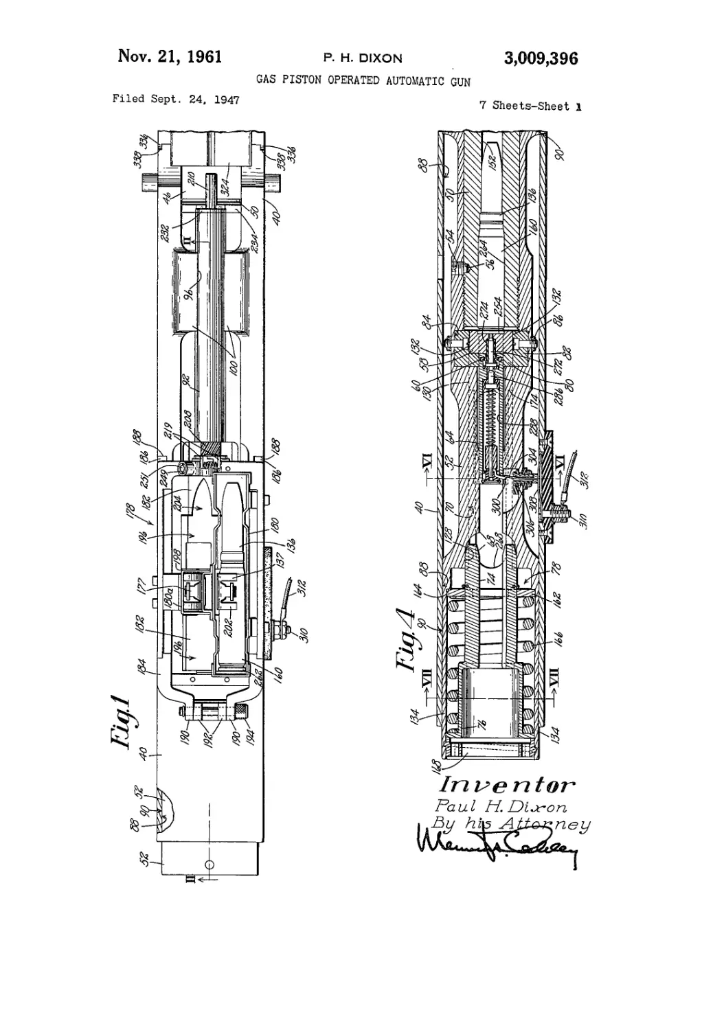
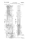
FIG. 1 is a plan view of the rear portion of the illus-
trative gun;
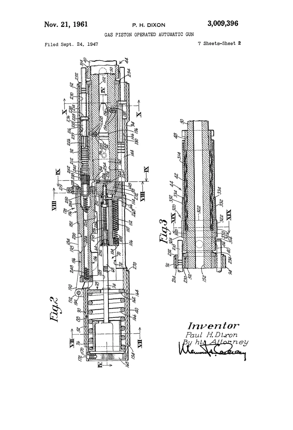
FIG. 2 is a vertical section on line II—II of FIG. 1;
a bolt assembly of the gun being shown in its battery posi-
tion ready for the firing of the gun;
FIG. 3 is a vertical section on a forward extension of
line II—II of FIG. 1 showing a recuperator of the gun;
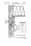
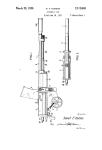
FIG. 4 is a horizontal section on line IV—IV of FIG. 2;
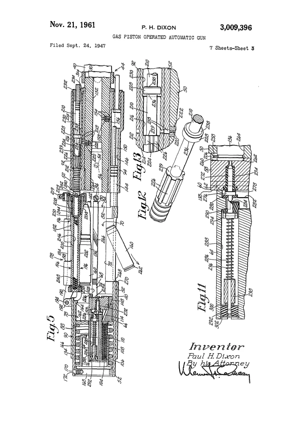
FIG. 5 is a view similar to FIG. 2 showing the gun
after it has been fired and the bolt assembly has been
moved to its fully recoiled position;
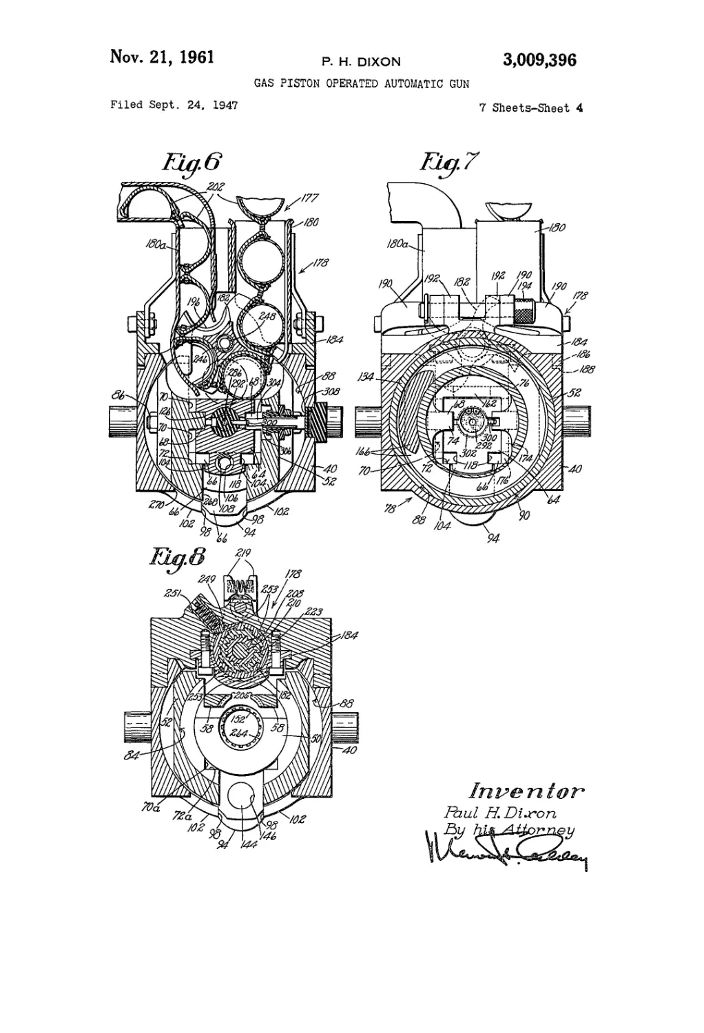
FIG. 6 is a section on line VI—VI of FIG. 4 illus-
trating cartridge feeding and electric ignition mechanism
of the gun;
FIG. 7 is a section on line VII—VII of FIG. 4 show-
ing a reaction unit of the gun; 35
FIG. 8 is a section on line VIII—VIII of FIG. 2;
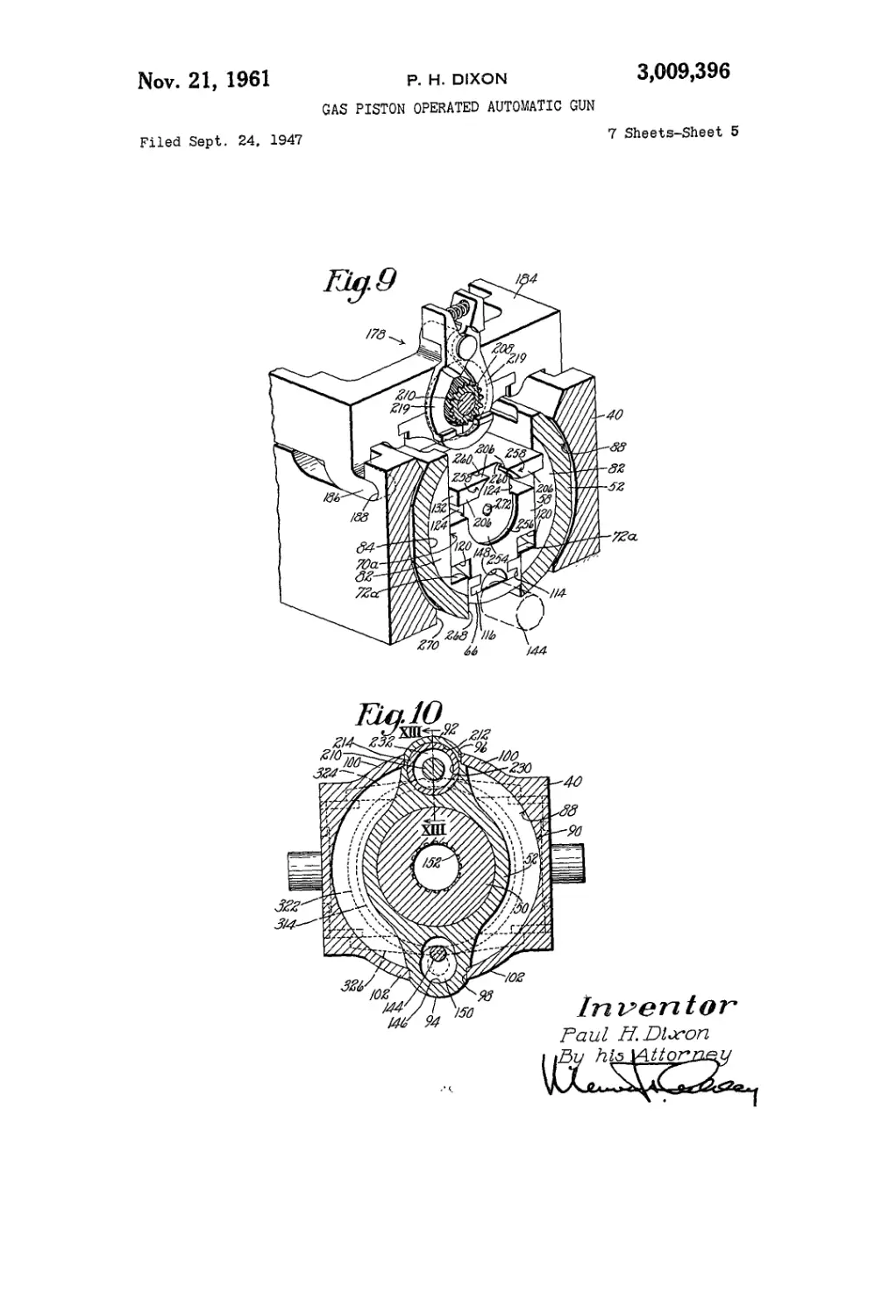
FIG. 9 is a perspective view partly in section on line
IX—IX of FIG. 2 showing the forward end of a bolt
and a feed box of the gun;
FIG. 10 is a section on line X—X of FIG. 2; 40
FIG. 11 is an enlarged vertical central section of por-
tions of the bolt and a slider of the bolt assembly;
FIG. 12 shows in perspective a gas operated piston
forming part of an ammunition feeder of the gun;
FIG. 13 is a section on line XIII—XIII of FIG. 10; 46
FIG. 14 shows in perspective the bolt assembly and a
bolt lock which may be secured to and forms in effect part
of the receiver of the gun;
FIG. 15 is an exploded view of the bolt assembly illus-
trated in FIG. 14; 50
FIG. 16 shows in perspective the bolt and portions of
the slider and a wedge forming part of the bolt assembly;
the bolt being in a locked battery position in front of
portions of the lock;
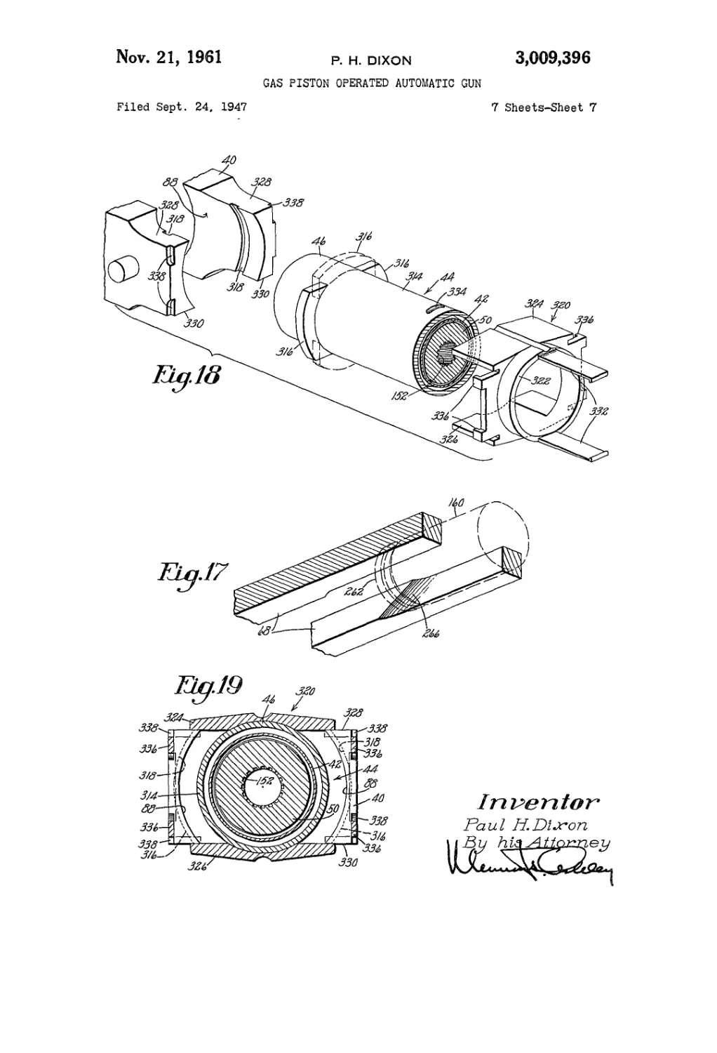
FIG. 17 is a perspective view illustrating portions of 53
bolt assembly guides or rails of the receiver and cartridge
case deflecting cams formed on said rails;
FIG. 18 is an exploded view showing portions of a
cradle and a recuperator, which cooperate to support the
gun for sliding movement in recoil and counter-recoil, 60
and also showing a bracket for locking the gun in opera-
tive position in the cradle and the recuperator; and
FIG. 19 is a section on line XIX—XIX of FIG. 3.
The illustrative gun is mounted in a cradle 40 which
may be secured to a turret (not shown) of an airplane ®5
for example, said gun being movable in recoil and counter-
recoil in the cradle approximately one-quarter of an
inch against the action of suitable ring springs 42 (FIGS.
3, 18 and 19) which form part of a recuperator 44
(FIGS. 3, 5 and 18) and are positioned between a recoil "°
housing assembly 46 (FIGS. 3, 18 and 19) secured,
3)009,393
3 4
the portions 74 of the rails 68 extending into said reac-
tion unit housing portion engage the bottoms of the chan-
nels 126, 124 of the slider 64 and the bolt 58 effectively
to guide these members without the assistance of the lat-
eral bearing faces 70 of the receiver.
The bolt 58 is moved to, and is held in, its raised bat-
tery position shown in FIG. 2 by the wedge 66, the con-
struction and arrangement being such that when the bolt
is in its lowered unlocked position in engagement with
the rear end of the barrel 50 after chambering a car-
tridge 136 (FIGS. 1, 2 and 5), the wedge 66 under its
own momentum and assisted by the spring 108, is moved
forward causing the bolt to be raised to its battery posi-
tion, rear faces 138 (FIGS. 14, 15 and 16) of the bolt
then being in front of and in engagement with front faces
of the abutments 80 and flanges 142 of the bolt lock 82 to
Lock the bolt 58 and accordingly the bolt assembly against
recoil movement. The slider 64 may be said to be slid-
ingly coupled to or interlocked with the bolt 60 and the
wedge 66.
After the gun has been fired the bolt 58 is lowered from
its raised battery position, to unlock it, by rearward
movement of the wedge 66 acted upon by a piston 144
(FIGS. 2, 5, 8, 9 and 10) which is slidable in a cylindri-
cal recess 146 formed in the downwardly projecting por-
tion 94 of the receiver 52 and acts against the front face
of the wedge 66. It will be noted that the bottom of the
bolt 58 has formed in it a tunnel 148 (FIGS. 2, 5 and 9)
to permit rearward movement of the piston 144 without
interfering with the free lowering of the bolt. The piston
144 has a shank portion of reduced diameter, an expan-
sion chamber 150 (FIGS. 2, 5 and 10) being formed be-
tween the cylindrical recess 146 and the shank portion
of the piston. Between the chamber 150 and a bore 152
of the barrel 50 is a gas passage 154 (FIGS. 2 and 5)
formed in part by a restricted orifice in a silver heat dissi-
pating plug 156 housed in a recess 158 of the barrel.
When the gun is fired the receiver 52, together with
the various gun parts supported by it, moves approximate-
ly one-quarter of an inch in recoil along the inside faces
88 of the cradle 40 against the action of the recuperator
44 (FIGS. 3 and 5) and then moves back to battery posi-
tion under the action of said recuperator. In the mean-
time, high pressure expanding gases from the bore 152
of the barrel 50 pass through the passage 154 into the
chamber 150 forcing the piston rod 144 with considerable
pressure against the front face of the wedge 66. When
the gun is first fired the rearward force of the explosion
against a case 160 of the expended cartridge 136 forces
the bolt 58 against front faces of the abutments 80 and
the flanges 142 of the bolt lock 82 with so much force
that the piston 144 acting through the wedge 66 does not
have sufficient power to move the bolt to its lowered un-
locked position. When the receiver 52 is near the end
of its recoil movement the pressure in the bore 152 of
the barrel 50 will have been reduced sufficiently to insure
against gases entering the receiver and rearward pressure
of the piston 144 acted upon by the expanding gases in
the chamber 150 moves the wedge 66 rearward against
the action of the spring 108 to a rearward position upon
the slider 64 and thus draws the bolt 58 downward until
the faces 120 (FIGS. 9, 14, 15 and 16) of the bolt 58 en-
gage the faces 72a of the bolt lock 82 of the receiver 64,
at which time the grooves or channels 124 of the bolt are
in register with the abutments 80 of the bolt lock 82.
The bolt 58, the slider 64 and the wedge 66 guided by the
rails 68 and the lateral bearing faces 70 of the receiver 52
are then moved in recoil under the action of the gas actu-
ated piston 144 with the assistance of the blow-back ac-
tion of the case 160 of the expended cartridge 136 against
the bolt. As explained in application for United States
Letters Patent Serial No. 716,469, filed December 16,
1946 in my name, it is sometimes desirable to insure
against any unbumed gases entering the receiver 52, in
which event the gas passage 154 is restricted sufficiently
to delay wedge actuating movement of the piston until
substantially all the unburned gases have left the bore 152
of the barrel 50.
The reaction unit 78 comprises a recessed plate 162
(FIGS. 2, 4, 5 and 7) which fits slidingly in the housing
5 portion 134 of the receiver 52 and is normally forced
against a transverse shoulder 164 of the receiver by a
spring 166. The spring 166 is initially compressed by the
retaining drum 76 held in the housing portion 134 of the
receiver 52 by a threaded rear cover 168 (FIGS. 2, 4 and
10 5) which is screwed into the rear end of the receiver
and is locked in its operative position in said receiver by
a spring-pressed plunger 170 (FIGS. 2 and 5) slidingly
mounted in the cover and constructed and arranged to
enter a hole 172 of the receiver. As the bolt assembly is
16 moved in recoil, opposite faces 174 (FIGS. 14, 15 and
16) of the slider 64 and opposite faces 176 of the wedge
66 engage the plate 162, the spring 166 being compressed
to absorb the energy of the bolt assembly and to effect
movement of said assembly in counter-recoil.
20 Cartridges 136 assembled in a belt 177 (FIGS. 1 and 6)
are automatically fed successively into a centralized ram-
ming position shown in FIG. 5 (dash line position FIG. 6)
in the receiver 52 of the gun, by an ammunition feeder
178 (FIGS. 1, 6 and 9) such as is fully disclosed in an
26 application for United States Letters Patent Serial No.
764,790, filed luly 30, 1947 in my name. Cartridges 136
in the belt 177 are fed down through a chute 180 to a car-
rier or sprocket 182 rotatably mounted in a feed box 184
which has at its forward end a pair of lugs 186 (FIGS. 7
30 and 9) constructed and arranged to fit in channels 188
of the cradle 40 and which has rearwardly extending arms
190 (FIGS. 1, 2, 5 and 7) spaced to include between them
an upstanding boss 192 of the cradle, said arms being
secured to said boss by a pin 194. The sprocket 182 is
36 provided with four cartridge receiving pockets 196 (FIGS.
1, 2, 5, and 6) which are interrupted by notches 198 (FIGS.
1, 2 and 5) and shallow recesses 200 shaped and arranged
to accommodate clips 202 (FIGS. 1 and 6) of the car-
tridge belt 177 and which have outwardly curved forward
40 ends 204 (FIGS. 1, 2 and 5) constructed and arranged to
cooperate with a rammer 206 hereinafter described and
formed integral with the bolt 58 for chambering the car-
tridge.
The sprocket 182 is rotated step by step in timed rela-
tion at the cyclic rate of the gun by a worm 208 (FIGS.
45 1, 2, 5, 8 and 9) mounted upon a piston 210 which is
reciprocable but not rotatable in a cylinder 212 (FIGS.
2, 5, 10 and 13) formed in part by a sleeve 214 secured
to the receiver 52, and which is operated by expanding
gases admitted to an intermediate bore 216 (FIGS. 2, 5
60 and 13) of the sleeve through a passage 218 extending
through the barrel 50, the receiver 52 and the sleeve 212.
The passage 218 is formed in part by a restricted bore
or passage 220 through a silver plug 222 housed in a
pocket of the barrel.
55 In splined relation with the sprocket 182 and held
against a shoulder of said sprocket by a pair of spring-
pressed locking arms 219 (FIGS. 1, 2, 5 and 9) is a nut
223 (FIGS. 2, 5 and 8) having internal spiral threads
meshing with external spiral threads of the worm 208
00 which, as will be hereinafter explained, during rearward
movement of the piston 210 under the action of expanding
gas pressure in the sleeve 214, is secured against rotation
on the piston.
The piston 210 is secured against rotation in the sleeve
06 214 by a plurality of longitudinal channels 224 (FIGS.
5 and 13) forming part of the sleeve and shaped and ar-
ranged to receive slidingly longitudinal flanges 226 (FIGS.
2, 5, 12 and 13) formed in the piston. The gun parts
are in their positions shown in HG. 2 when the initial
round of a burst of cartridges 136 is fired, expanding gases
in the bore 152 of the barrel 50 thereafter traveling
through the passages 218, 220 into the intermediate bore
216 of the sleeve 214 and around a flange 228 of the pis-
ton 210 into a large bore 230 (FIGS. 2, 3, 5, 10 and 13)
of the sleeve. The forward end of the sleeve 214 is closed
3,009,396
5
by a plug 232 (FIGS. 1, 2, 3, 5 and 10) which is forced
into said sleeve by a collar 234 carried by the barrel 50
and backed up by a flange on said barrel, the plug being
inserted in the bore 230 of the sleeve 214 at the time that
the barrel is threaded into the receiver 52. When the
piston 210 is in the position illustrated in FIGS. 2 and 13
high pressure gases admitted to the intermediate and large
bores 216, 230 of the sleeve 214, which bores at that time
are in communication, cause rearward movement of the
piston by reason of unbalanced gas pressure against op-
posed faces 236, 238 of the flange 228 of the piston and a
face 239 (FIGS. 2, 5, 12 and 13) at the forward end of
the longitudinally flanged portion 226 of said piston with
the result that four recesses 240 (FIGS. 2 and 5) (only
one shown) in the piston move into interlocking relation
with opposed studs 242 at the forward end of the worm
208, then in its forward position shown in FIG. 2. The
piston 210 thereafter causes the worm 208 to slide rear-
ward with it until the rear end of said worm engages a
transverse face 244 (FIGS. 2 and 5) of an axially extend-
ing bore 246 in the sprocket 182, movement of the piston
being resisted by a spring 248 housed in the bore and hav-
ing its forward end in engagement with a collar 250 se-
cured to the piston.
Rearward movement of the worm 208 in meshing en-
gagement with the nut 223 and interlocked against rota-
tion upon the piston 210 will effect clockwise rotation of
the sprocket 182, as viewed in FIG. 6, causing the leading
cartridge 136 in the belt 177 to be forced against the slider
64 and the bolt 58, which at that time are moving in recoil
and are in such positions as to prevent the cartridge from
being moved to its central or ramming position shown in
FIG. 5 (dash line position as shown in FIG. 6) in the re-
ceiver 52. After the bolt 58 has moved to a recoil posi-
tion rearward of and out of engagement with the lead-
ing cartridge 136 in the belt 177, the piston 210 is moved
further rearward by the expanding gases until the worm
208 engages the face 244 of the bore 246 in the sprocket
182 at which time said leading cartridge in the belt is in its
central or ramming position and the sprocket may be said
to be in its indexed position. The sprocket 182 is held
in its indexed position by a spring-pressed plunger 249
(FIGS. 1 and 8) which is slidingly mounted in a guide-
way 251 of the feed box 184 and has its lower end in en-
gagement with one of four recesses 253 (FIG. 8) in the
nut 223.
When the bolt 58 is in battery position the rear end
of the cartridge 136, as illustrated in FIG. 2, is in engage-
ment with a vertical face 254 (FIGS. 2, 4, 5 and 9) of a
recess 256 (FIG. 9) in the forward end of the bolt which
has ramming faces 258 and slots 260. After the gun has
been fired and the bolt 58 has been moved to its lowered
unlocked position ready to be moved in recoil together
with the slider 64, the upper edge of the rim 262 of the
case 160 of the spent cartridge 136 is in the slots 260 with
the result that said case, upon recoil movement of the
bolt, is extracted from a cartridge chamber 264 of the
bore 152 of the barrel 50. As the case 160 of the spent
cartridge 136 is extracted from the cartridge chamber 264,
the upper edge of its rear end engages cam surfaces 266
(FIGS. 5 and 17) of the rails 68 causing said case to be
deflected downward through alined openings 268, 270
(FIGS. 2, 5, 6 and 9) formed in the receiver 52 and the
cradle 40 respectively. The bolt 58 may be said to com-
prise the rammer or spaced arms 206 which extend or
project forwardly from the upper lateral portions of the
vertical face 254 and have undercut opposing faces, the
slots 260 being formed in said arms and having their rear
faces continuous with said vertical face.
As the bolt assembly is moved forward in counter-
recoil the faces 258 of the rammer 206 engage the rear
end of the cartridge 136 then in the belt 177 and in ram-
ming position, causing the forward end of said cartridge
to be moved forward and deflected downward out of its
associated cartridge clip 202 of the belt by reason of the
6
10
15
20
25
30
35
40
45
50
55
60
65
70
75
6
cooperative action of the forward portion 204 of the
pocket 196 of the sprocket 182 and the cartridge clasping
clip 202 of the belt. As soon as the cartridge 136 leaves
the belt 177 its rear end drops below the faces 258 of
the rammer 206 and is engaged by the vertical face 254
of the bolt 58, continued forward movement of the bolt
causing the cartridge to be chambered, the rim 262 during
the chambering action being raised into the slots 260 in
the bolt. As soon as the bolt 58 engages the rear end
of the barrel 50 the wedge 66 under its own momentum
and actuated by the spring 248 moves forward to its bat-
tery position shown in FIGS. 2 and 16 causing the bolt
58 to be raised to its locked battery position in which the
rear faces 138 of the bolt are locked in front of the
flanges 142 and the abutments 80 of the bolt lock 82.
The cartridge 136 is fired electrically by an electrode
or firing pin 272 (FIGS. 2, 4, 5, 9, 11 and 15) which is
mounted for sliding movement in an insulating sleeve 274
secured to the bolt 58 and has fixed to it a collar 276
(FIGS. 11 and 15) the electrode being constantly urged
rearward with relation to the bolt by a spring disk washer
278, the forward end of the electrode at the time the bolt
is unlocked being positioned just behind the face 254 of
the bolt. Secured to the collar 276 of the electrode 272
is an insulating disk 280 which by the action of the spring
disk washer 278 is forced against and slides along a
face 282 (FIG. 11) of the slider, which face constitutes
a stop, as the bolt 58 is raised to and lowered from its
locked battery position.
When the bolt 58 is in its locked battery position
shown in FIGS. 2 and 11 the rear end of the electrode
272 is in engagement with an inclined forward surface
284 (FIG. 11) of a rod or conductor 286 (FIGS. 2, 4, 6,
11 and 16) positioned in a longitudinal recess 288 (FIGS.
4, 5 and 11) of the slider 64 and mounted for longitudi-
nal sliding movement in insulating blocks 290, 292 (FIG.
11) secured to the slider. The rod 286 is constantly
urged to the right as viewed in FIG. 11 to a position in
which a flange 294 of the rod is substantially in engage-
ment with the insulating block 290, by a spring 296
(FIGS. 2, 11 and 16) which encircles the rod and the
forward and rear ends of which the flange 294 and a
spacer block 298 (FIGS. 2, 5 and 11) carried by the rod.
Secured to the rod 286 and arranged between the spacer
block 298 and the insulating block 292 is a conductor 300.
The rod 286, together with the parts mounted on it, is
inserted in its proper position in the slider, the insulating
block 292 being pressed forward into position in the
slider and held in such position by a snap spring 302
(FIGS. 7, 11, 14 and 15). During the forward end of
the counter-recoil movement of the slider 64 the con-
ductor 300 engages a flexible leaf spring 304 (FIGS. 4
and 6) which is mounted in an insulating tube 306 se-
cured to the receiver 52 and is in sliding engagement with
a leaf spring conductor 308 secured to a screw 310 fixed
to the cradle 40, current being supplied to the screw
by a cable 312 leading to a source of power. As the
slider 64 moves forward in counter-recoil the conduc-
tor 300 engages the energized leaf spring 304 and as the
bolt 58 is raised to its battery position the rear end of
the electrode 272 carried by the bolt engages the front
face 284 of the spring-pressed rod 286 which moves the
collar 276 of the electrode 272 to the right (FIG. 11)
against the action of the spring washer 278 thereby caus-
ing the forward end of said electrode to project slightly
beyond the face 254 of the bolt 58 in order to contact
the rear end of the chambered cartridge 136 to fire said
cartridge.
Guns of airplanes are commonly overhauled after each
mission, and accordingly, it is desirable that burned out
guns be quickly removed from their cradles 40 and over-
hauled guns be substituted therefor. With the foregoing
consideration in view, a cylindrical spring housing 314
(FIGS. 2, 3, 5, 18 and 19) forming part of the recuper-
ator 44 has formed integral with it a pair of laterally
3,009,396
7
extending flanges 316 (FIGS. 18 and 19) which are con-
structed and arranged to fit in arcuate slots 318 formed
in the cradle 40. Before removing the burned out gun
from the cradle the feed box 184 is removed from the
cradle by removing the pin 194 and lifting said box from
the cradle. After removing a locking bracket 320 (FIGS.
3, 18 and 19), which will be described later, from its
locking position on the gun the spring housing 314 is
rotateed 90° until its flanges 316 are in dash-line posi-
tion shown in FIG. 18, the receiver then being slid for-
ward out through the front of the cradle 40.
In mounting a reconditioned gun in the cradle, the
receiver of the gun is slid rearward into the cradle and
the spring housing 314 is then rotated causing its flanges
316 to engage in the arcuate grooves 318 of the cradle,
said housing thus being secured against lengthwise move-
ment in the cradle. To insure against displacement of
the spring housing 314 thus positioned in the cradle 40
there is provided the above-mentioned locking bracket
320 (FIGS. 3, 18 and 19) which has a circular portion
322 constructed and arranged to fit slidingly on the spring
housing 314 and which, when arranged in its locking
position, has upper and lower plates 324, 326 thereof
in enaggement with upper and lower surfaces 328, 330
respectively of the cradle, inturned ends of arms 332 ex-
tending forward from the circular portion 322 fitting in
slots 334 of the spring housing, and four rearwardly
extending lugs 336 fitting in grooves 338 respectively of
the cradle 40, the construction and arrangement being
such that the spring housing is held against rotation on
the cradle. It will thus be apparent that the guns may
be quickly and effectively removed from and assembled
in the cradle.
Having thus described my invention what I claim as
new and desire to secure by Letters Patent of the United
States is:
An automatic gun comprising a barrel, a receiver
which is secured to the barrel and has longitudinal guides,
a bolt lock having abutments which are in alinement
with said guides, a slider movable longitudinally of the
5
10
15
20
25
30
35
40
8
receiver in recoil and counter-recoil upon said guides and
said abutments, a bolt which is coupled for longitudinal
movement with the slider and is slidable heightwise of
the receiver with relation to the slider, said bolt having,
at its lower end a projection extending longitudinally
and heightwise of the receiver, a wedge mounted for
longitudinal movement upon the slider and having a
guideway which extends longitudinally and heightwise
of the receiver and is constructed and arranged slidingly
to receive the projection of the bolt, a stop carried by the
receiver, and a gas operated piston movable a short dis-
tance in recoil under the action of high pressure expand-
ing gases between a battery position adjacent to the
wedge and a rest position against the stop, said piston
during movement from its battery to its rest position be-
ing adapted to move the wedge rearward upon the slider
thereby effecting heightwise movement of the bolt upon
the slider from a raised locked position in front of the
abutments of the’bolt lock to a lowered unlocked posi-
tion and then to impart to the wedge sufficient energy
to move the wedge together with the slider and the bolt
as a unit a substantial distance in recoil.
References Cited in the-file of this patent
UNITED STATES PATENTS
532,380 Johnson____________________Jan. 8, 1895
781,503 Driggs-------------------Jan. 31, 1905
862,384 Bristol____________________Aug. 6, 1907
1,290,854 Sturgeon ________________ Jan. 7, 1919
1,709,162 Westervelt et al.________Apr. 16, 1929
1,821,463 Danthine_________________Sept. 1, 1931
1,852,057 Moore et al._____________Apr. 5, 1932
2,077,415 House____________________Apr. 20, 1937
2,204,289 Williams_________________June 11, 1940
2,223,004 Holek____________________Nov. 26, 1940
2,313,030 Tauschek_________________ Mar. 2, 1943
2,359,517 Gebeau __________________ Oct. 3, 1944
2,436,937 Rataiczak________________Mar. 2, 1948
2,462,889 Nedihardt________________Mar. 1, 1949