/

Tags: weapons military affairs machine gun patent
Year: 1902
Text
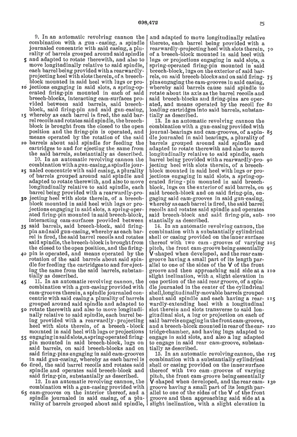
No. 698,472.
Patented Apr. 29, 1902.
L. L. DRIGGS.
AUTOMATIC GUN.
THE NORRIS PETERS
CO , PHOTO LITHO . WASHINGTON. О C
Patented Apr. 29, 1902.
No. 698,472.
L. L. DRIGGS.
AUTOMATIC GUN.
tApplication filed Aug. 24. 1897.1
THE MORRIS PETERS CO, PHOTO-UTHO . WASHINGTON D C
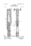
No. 698,472. Patented Apr. 29, 1902.
L. L. DRIGGS.
AUTOMATIC GUN.
(Application filed Aug. 24. 1897.)
(No Model.) 4 Sheets—Sheet 3.
THE NOffRlS PETERS CO , PHOTO-LITKO . WASHINGTON. О C.
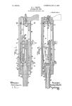
Patented Apr. 29, 1902.
No. 698,472.
L. L. DRIGGS.
AUTOMATIC GUN.
(Application filed Aug. 24. 1897.)
(No Model.)
4 Sheets—Sheet 4.
THE NORFtiS PETERS CO . PHOTO-LlTHO.. WASHINGTON. D
United States Patent Office.
LOTTIS LABADIE DRIGGS, OF WASHINGTON, DISTRICT OF COLUMBIA, AS-
SIGNOR TO DRIGGS-SEABURY GUN AND AMMUNITION COMPANY, OF
NEW YORK, N. Y., A CORPORATION OF NEW JERSEY.
AUTOMATIC GUN.
SPECIFICАТ10Я forming part of Letters Patent No. 698,472, dated April 29, 1902.
Application filed August 24,1897. Serial Ho. 649,369. (Ho model.)
To all whom it may concern:
Be it known that I, Louis Labadie Driggs,
a citizen of the United States, residing at
Washington,in. the District of Columbia, have
5 invented certain new and useful Improve-
ments in Automatic Guns; and I do hereby
declare the following to be a full, clear, and
exact description of the invention, such as
will enable others skilled in the art to which
to it appertains to make and use the same.
My invention relates-to improvements in
automatic revolving guns in which there are
a plurality of barrels and in which each bar-
rel recoils as it fires' and exerts a part of the
15 energy of the recoil in moving the other bar-
rels toward the firing position.
My invention also consists of certain other
novel features that will be more fully de-
scribed and claimed.
20 Reference is had to the accompanying draw-
ings, in which the same parts are indicated
throughout the several views by the same
characters.
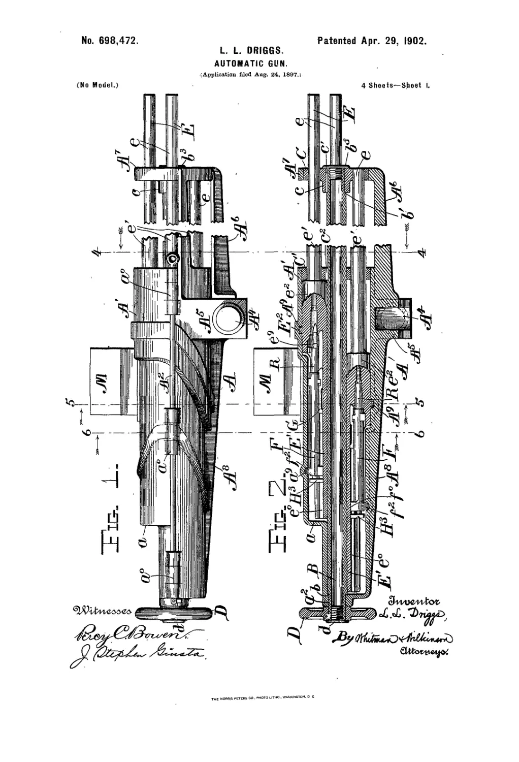
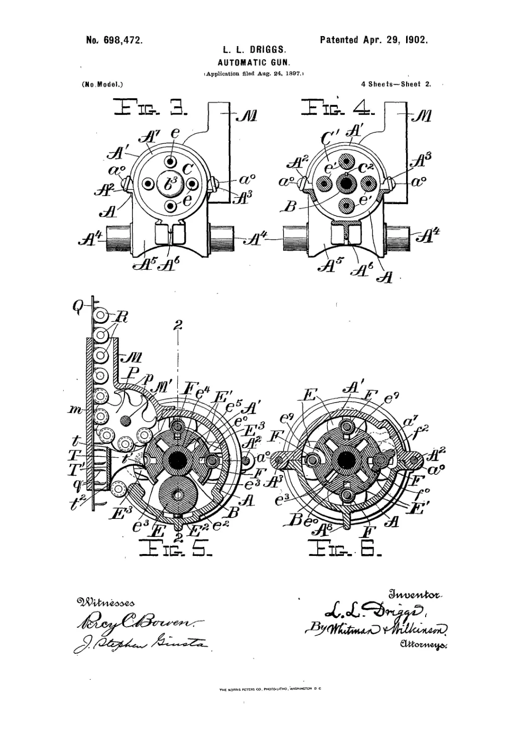
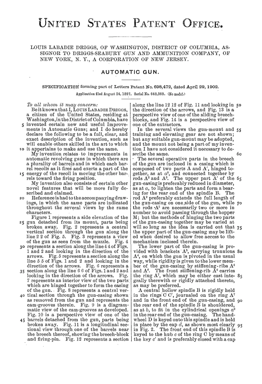
Figure 1 represents a side elevation of the
25 gun detached from its mount, parts being
broken away. Fig. 2 represents a central
vertical section through the gun along the
line 2 2 of Fig. 5. Fig. 3 represents a view
of the gun as seen from the muzzle. Fig. 4
30 represents a section alongtheline44of Figs.
1 and 2 and looking in the direction of the
arrows. Fig. 5 represents a section along the
line 5 5 of Figs. 1 and 2 and looking in the
direction of the arrows. Fig. 6 represents a
35 section along the line 6 6 of Figs. 1 and 2 and
looking in the direction of the arrows. Fig.
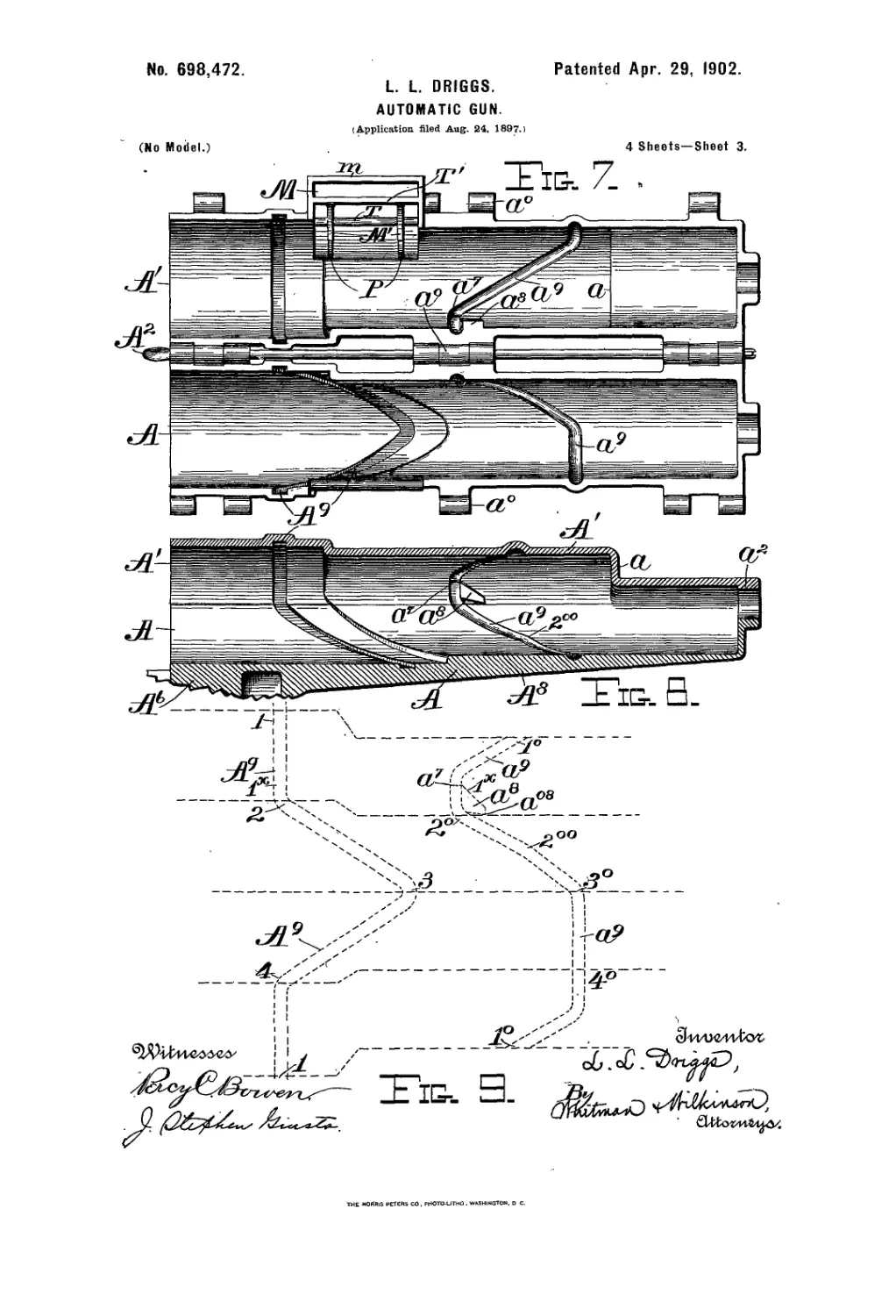
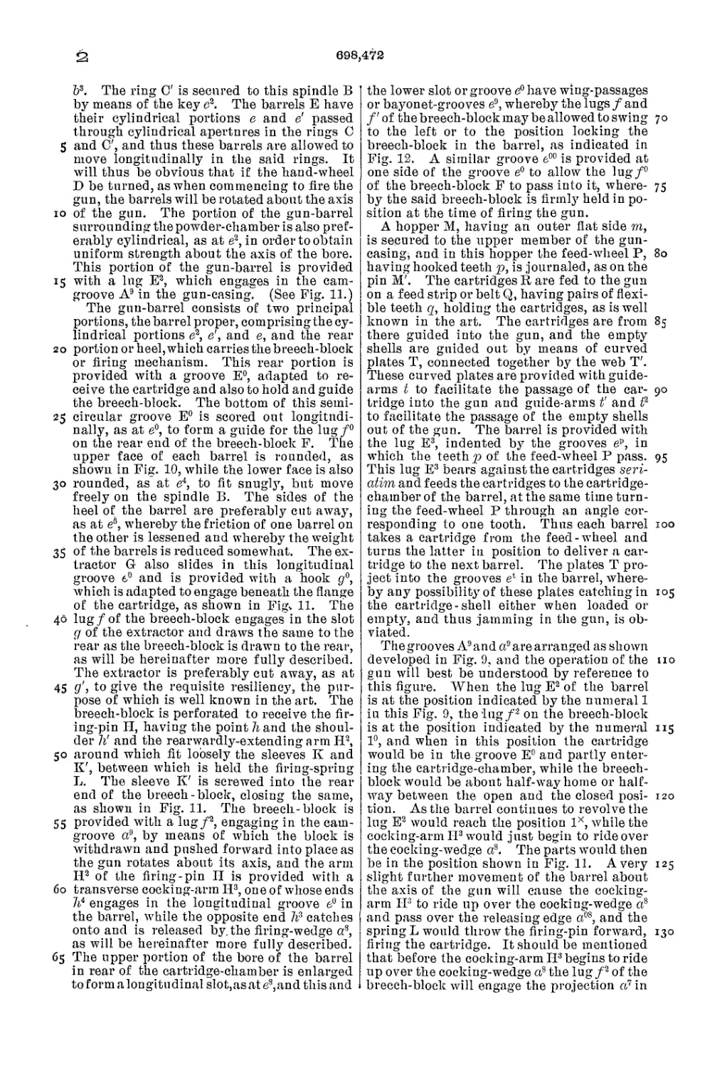
7 represents an interior view of the two parts,
which are hinged together to form the casing
of the gun. . Fig. 8 represents a central ver-
40 tical section through the gun-casing shown
as removed from the gun and represents the
cam-grooves therein. Fig. 9 is a diagram-
matic view of the cam-grooves as developed.
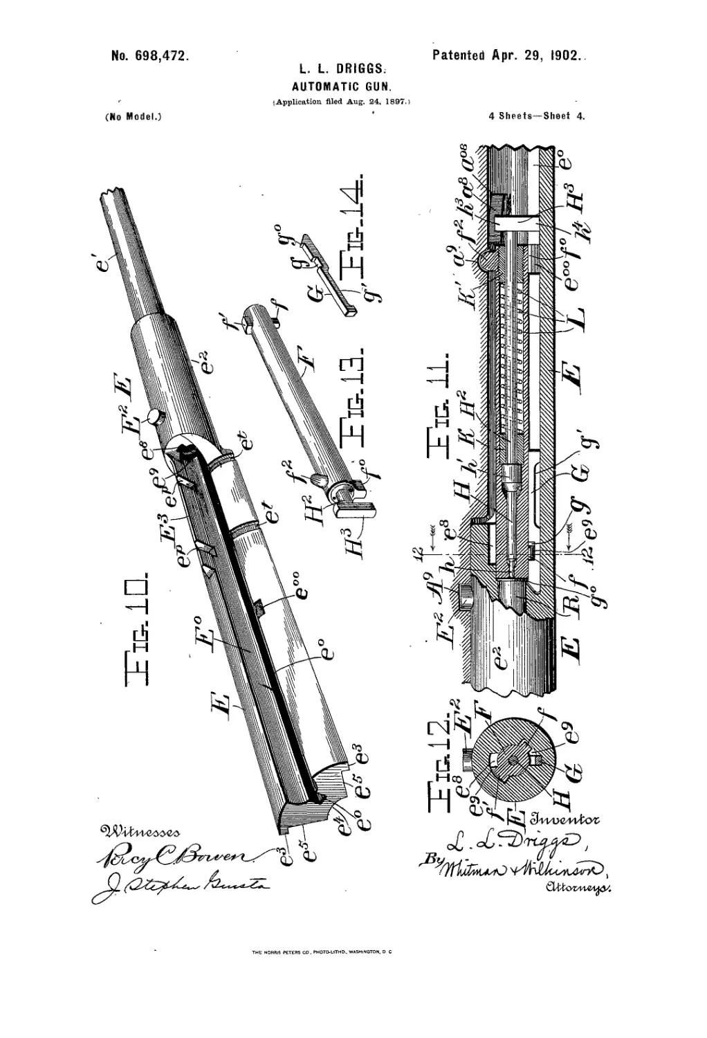
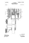
Fig. 10 is a perspective view of one of the
45 barrels detached from tho gun, parts being
broken away. Fig..11 is a longitudinal sec-
tional view throughone of the barrels near
the breech thereof, showing the breech-block
and firing-pin. Fig. 12 represents a section
along the line 12 12 of Fig. 11 and looking in
the direction of the arrows, and Fig. 13 is a
perspective view of one of the sliding breech-
blocks, and Fig. 14 is a perspective view of
one of the extractors.
5°
In the several views the gun-mount and 55
training and elevating gear are not shown;
but any suitable gun-mount may be adopted,
and the mount not being a part of my inven-
tion I have not considered it necessary to de-
scribe the same. 60
- The several operative parts in the breech
of the gun are inclosed in a casing which is
composed of two parts A and A', hinged to-
gether, as at a°, and connected together by
rods A2 and A3. The upper part A' of the 65
gun-casing is preferably reduced in diameter^
as at a, to lighten the parts and form a bear-
ing for the rear end of the spindle B. The
rod A2 preferably extends the full length of
the gun-casing on one.side of the gun, while 70
the rods A.3 are necessarily two or more in
number to avoid passing through the hopper
M; but the methods of hinging the two parts
of the gun-casing together may be varied at
will so long as the idea is carried out that 75
the upper part of the gun-casing may be lift-
ed when desired to allow free access to the
mechanism inclosed therein.
The lower part of the gun-casing is pro-
vided with brackets As, carrying trunnions 80
A4, on which the gun is pivoted in the usual
way, while rigidity is given to the lower mem-
ber of the gun-casing by stiffening-ribs A°
and A8. The front stiffening-rib Ae carries
the ring A7, which may be either cast inte- 85
grally therewith or rigidly attached thereto,
as may be preferred.
A central hollow spindle В is rigidly held
in the rings’С C', journaled on the ring A7
and in the front end of the gun-casing, and 90
the rear end of the spindle В is shouldered,
as at Ъ, to fit in the cylindrical openings a?
in the rear end of the gun-casing. The hand-
wheel D is keyed onto this spindle and is held
in place by the cap d, as shown most clearly 95
in Fig. 2. The front end of this spindle В is
keyed to the hub c of the ring C by means of
the key c' and is preferably closed with a cap
698,472
b3. The ring C' is secured to this spindle В
by means of the key c2. The barrels E have
their cylindrical portions e and e' passed
through cylindrical apertures in the rings C
5 and O', and thus these barrels are allowed to
move longitudinally in the said rings. It
will thus be obvious that if the hand-wheel
D be turned, as when commencing to fire the
gun, the barrels will be rotated about the axis
io of the gun. The portion of the gun-barrel
surrounding the powder-chamber is also pref-
erably cylindrical, as at e2, in order to obtain
uniform strength about the axis of the bore.
This portion of the gun-barrel is provided
15 with a lug E2, which engages in the cam-
groove A9 in the gun-casing. (See Fig. 11.)
The gun-barrel consists of two principal
portions, the barrel proper, comprising the cy-
lindrical portions e2, e', and e, and the rear
20 portion or heel, which carries the breech-block
or firing mechanism. This rear portion is
provided with a groove E°, adapted to re-
ceive the cartridge and also to hold and guide
the breech-block. The bottom of this semi-
25 circular groove E° is scored out longitudi-
nally, as at e°, to form a guide for the lug/0
on the rear end of the breech-block F. The
upper face of each barrel is rounded, as
shown in Fig. 10, while the lower face is also
30 rounded, as at e4, to fit snugly, but move
freely on the spindle B. The sides of the
heel of the barrel are preferably cut away,
as at e5, whereby the friction of one barrel on
the other is lessened and whereby the weight
35 of the barrels is reduced somewhat. The ex-
tractor G also slides in this longitudinal
groove 6° and is provided with a hook p°,
which is adapted to engage beneath the flange
of the cartridge, as shown in Fig. 11. The
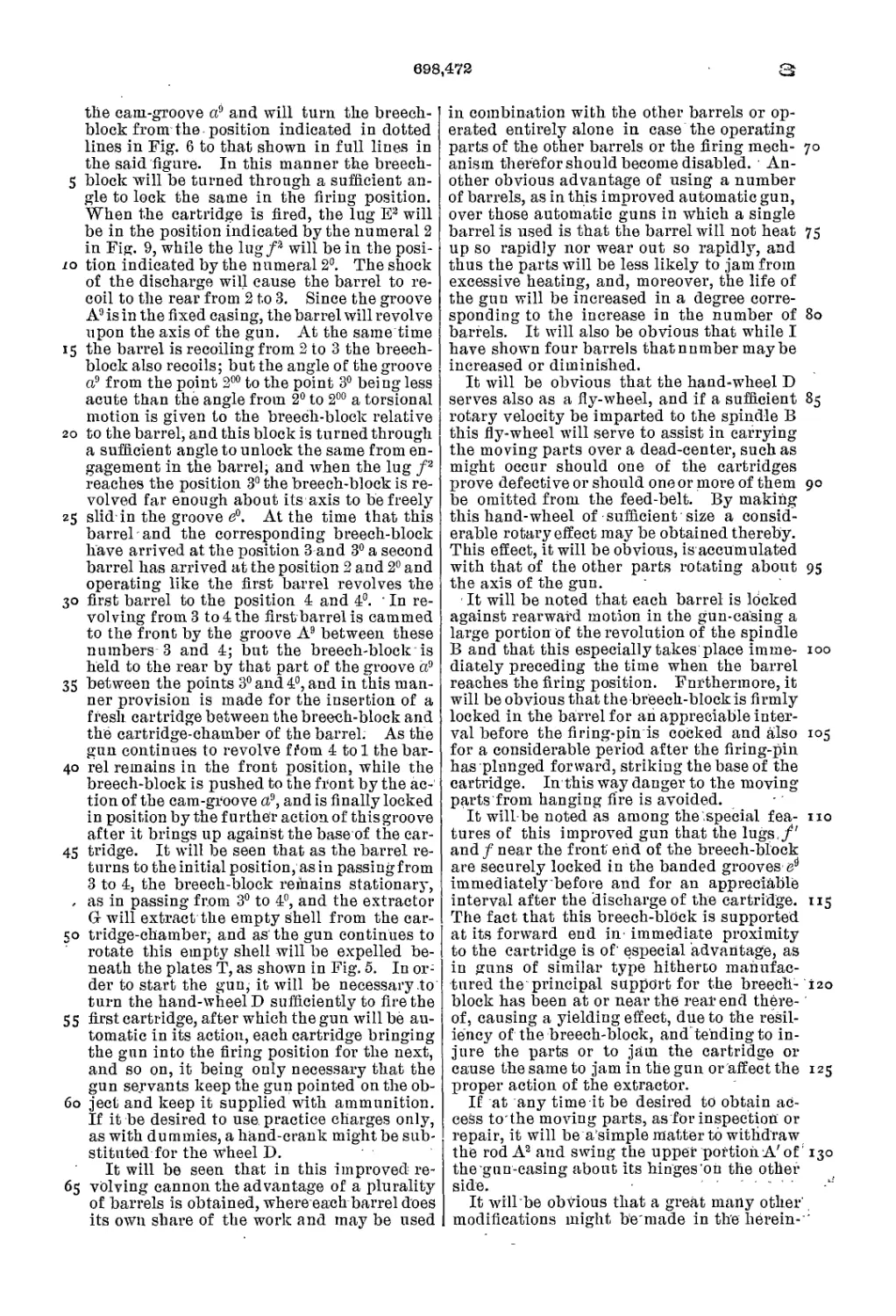
40 lug/of the breech-block engages in the slot
g of the extractor and draws the same to the
rear as the breech-block is drawn to the rear,
as will be hereinafter more fully described.
The extractor is preferably cut away, as at
45 to give the requisite resiliency, the pur-
pose of which is well known in the art. The
breech-block is perforated to receive the fir-
ing-pin II, having the point 7г and the shoul-
der 7г' and the rearwardly-extending arm H2,
50 around which fit loosely the sleeves К and
K', between which is held the firing-spring
L. The sleeve K' is screwed into the rear
end of the breech-block, closing the same,
as shown in Fig. 11. The breech-block is
55 provided with a lug/2, engaging in the cam-
groove a9, by means of which the block is
withdrawn and pushed forward into place as
the gun rotates about its axis, and the arm
H2 of the firing-pin II is provided with a
60 transverse cocking-arm II3, one of whose ends
7г4 engages in the longitudinal groove e° in
the barrel, while the opposite end 7г3 catches
onto and is released by. the firing-wedge a8,
as will be hereinafter more fully described.
65 The upper portion of the bore of the barrel
in rear of the cartridge-chamber is enlarged
to form a longitudinal slot,as at e8,and this and
the lower slot or groove e° have wing-passages
or bayonet-grooves e9, whereby the lugs / and
/' of the breech-block may be allowed to swing 7 о
to the left or to the position locking the
breech-block in the barrel, as indicated in
Fig. 12. A similar groove e00 is provided at
one side of the groove e° to allow the lug/0
of the breech-block F to pass into it, where- 75
by the said breech-block is firmly held in po-
sition at the time of firing the gun.
A hopper M, having an outer flat side m,
is secured to the upper member of the gun-
casing, and in this hopper the feed-wheel P, 80
having hooked teeth p, is journaled, as on the
pin M'. The cartridges R are fed to the gun
on a feed strip or belt Q, having pairs of flexi-
ble teeth q, holding the cartridges, as is well
known in the art. The cartridges are from 85
there guided into the gun, and the empty
shells are guided out by means of curved
plates T, connected together by the web T'.
These curved plates are provided with guide-
arms t to facilitate the passage of the car- 90
tridge into the gun and guide-arms tr and 72
to facilitate the passage of the empty shells
out of the gun. The barrel is provided with
the lug E3, indented by the grooves ep, in
which the teeth p of the feed-wheel P pass. 95
This lug E3 bears against the cartridges seri-
atim and feeds the cartridges to the cartridge-
chamber of the barrel, at the same time turn-
ing the feed-wheel P through an angle cor-
responding to one tooth. Thus each barrel 100
takes a cartridge from the feed-wheel and
turns the latter in position to deliver a car-
tridge to the next barrel. The plates T pro-
ject into the grooves e‘ in the barrel, where-
by any possibility of these plates catching in 105
the cartridge-shell either when loaded or
empty, and thus jamming in the gun, is ob-
viated.
The grooves A9 and a9 are arranged as shown
developed in Fig. 9, and the operation of the no
gun will best be understood by reference to
this figure. When the lug E2 of the barrel
is at the position indicated by the numeral 1
in this Fig. 9, the lug/2 on the breech-block
is at the position indicated by the numeral 115
1°, and when in this position the cartridge
would be in the groove E° and partly enter-
ing the cartridge-chamber, while the breech-
block would be about half-way home or half-
way between the open and the closed posi- 120
tion. As the barrel continues to revolve the
lug E2 would reach the position Iх, while the
cocking-arm II3 wrould just begin to ride over
the cocking-wedge a8. The parts would then
be in the position shown in Fig. 11. Avery 125
slight further movement of the barrel about
the axis of the gun will cause the cocking-
arm II3 to ride up over the cocking-wedge a8
and pass over the releasing edge a08, and the
spring L would throw the firing-pin forward, 130
firing the cartridge. It should be mentioned
that before the cocking-arm II3 begins to ride
up over the cocking-wedge a8 the lug /2 of the
breech-block will engage the projection ci7 in
698,472
tlie cam-groove a? and will turn the breech-
block from the position indicated in dotted
lines in Fig. 6 to that shown in full lines in
the said figure. In this manner the breech-
5 block will be turned through a sufficient an-
gle to lock the same in the firing position.
When the cartridge is fired, the lug E2 will
be in the position indicated by the numeral 2
in Fig. 9, while the lug/3 will be in the posi-
io tion indicated by the numeral 2°. The shock
of the discharge will cause the barrel to re-
coil to the rear from 2 to 3. Since the groove
A9 is in the fixed casing, the barrel will revolve
upon the axis of the gun. At the same time
15 the barrel is recoiling from 2 to 3 the breech-
block also recoils; but the angle of the groove
a9 from the point 2°° to the point 3° being less
acute than the angle from 2° to 2°° a torsional
motion is given to the breech-block relative
20 to the barrel, and this block is turned through
a sufficient angle to unlock the same from en-
gagement in the barrel, and when the lug f2
reaches the position 3° the breech-block is re-
volved far enough about its axis to be freely
25 slid in the groove e°. At the time that this
barrel and the corresponding breech-block
have arrived at the position 3 and 3° a second
barrel has arrived at the position 2 and 2° and
operating like the first barrel revolves the
30 first barrel to the position 4 and 4°. ‘ In re-
volving from.3 to 4 the first barrel is cammed
to the front by the groove A9 between these
numbers 3 and 4; but the breech-block is
held to the rear by that part of the groove a9
35 between the points 30and4°, and in this man-
ner provision is made for the insertion of a
fresh cartridge between the breech-block and
the cartridge-chamber of the barrel. As the
gun continues to revolve fi’om 4 tol the bar-
40 rel remains in the front position, while the
breech-block is pushed to the front by the ac-
tion of the cam-groove a9, and is finally locked
in position by the further action of this groove
after it brings up against the base of the car-
45 tridge. It will be seen that as the barrel re-
turns to the initial position, as in passingfrom
3 to 4, the breech-block remains stationary,
, as in passing from 3° to 4°, and the extractor
G will extract the empty shell from the car-
50 tridge-chamber, and as'the gun continues to
rotate this empty shell will be expelled be-
neath the plates T, as shown in Fig. 5. In or-
der to start the gun, it will be necessary .to
turn the hand-wheel D sufficiently to fire the
55 first cartridge, after which the gun will be au-
tomatic in its action, each cartridge bringing
the gun into the firing position for the next,
and so on, it being only necessary that the
gun servants keep the gun pointed on the ob-
60 ject and keep it supplied with ammunition.
If it be desired to use practice charges only,
as with dummies, a hand-crank might be sub-
stituted for the wheel D.
It will be seen that in this improved re-
65 volving cannon the advantage of a plurality
of barrels is obtained, where each barrel does
its own share of the work and may be used
in combination with the other barrels or op-
erated entirely alone in case the operating
parts of the other barrels or the firing mech- 70
anism therefor should become disabled. An-
other obvious advantage of using a number
of barrels, as in this improved automatic gun,
over those automatic guns in which a single
barrel is used is that the barrel will not heat 75
up so rapidly nor wear out so rapidly, and
thus the parts will be less likely to jam from
excessive heating, and, moreover, the life of
the gun will be increased in a degree corre-
sponding to the increase in the number of 80
barrels. It will also be obvious that while I
have shown four barrels thatnnmber maybe
increased or diminished.
It will be obvious that the hand-wheel D
serves also as a fly-wheel, and if a sufficient 85
rotary velocity be imparted to the spindle В
this fly-wheel will serve to assist in carrying
the moving parts over a dead-center, such as
might occur should one of the cartridges
prove defective or should one or more of them 90
be omitted from the feed-belt. By making
this hand-wheel of sufficient size a consid-
erable rotary effect may be obtained thereby.
This effect, it will be obvious, is accumulated
with that of the other parts rotating about 95
the axis of the gun.
It will be noted that each barrel is locked
against rearward motion in the gun-casing a
large portion of the revolution of the spindle
В and that this especially takes place imme- 100
diately preceding the time when the barrel
reaches the firing position. Furthermore, it
will be obvious that the breech-block is firmly
locked in the barrel for an appreciable inter-
val before the firing-pin is cocked and also 105
for a considerable period after the firing-pin
has plnnged forward, striking the base of the
cartridge. In this way danger to the moving
parts from hanging fire is avoided.
It will be noted as among the .special fea- no
tures of this improved gun that the lugs,/'
and / near the front end of the breech-block
are securely locked in the banded grooves es
immediately before and for an appreciable
interval after the discharge of the cartridge. 115
The fact that this breech-block is supported
at its forward end in- immediate proximity
to the cartridge is of' especial advantage, as
in guns of similar type hitherto manufac-
tured the principal support for the breech- i20
block has been at or near the rear end there-
of, causing a yielding effect, due to the resil-
iency of the breech-block, and tending to in-
jure the parts or to jam the cartridge or
cause the same to jam in the gun or affect the 125
proper action of the extractor.
If at any time it be desired to obtain ac-
cess to the moving parts, as for inspection or
repair, it will be a’simple matter to withdraw
the rod A2 and swing the upper portion A' of’ 130
the gun-casing about its hinges oh the other
side. ......
It will be obvious that a great many other'
modifications might be'made in the herein- ’
698,472
described apparatus which could be used
without departing from the spirit of my in-
vention.
Having thus described my invention, what
5 I claim, and desire to secure by Letters Pat-
ent of the United States, is—
1. In an automatic gun, the combination
with a gun-casing, a spindle journaled concen-
tric with said casing, a plurality of barrels
io having rearwardly-extending heels grouped
around said spindle and rotating therewith,
guides mounted on said spindle and allowing
said barrels to move longitudinally relative
to said spindle, and interacting cam-surfaces
15 between said barrels and said gun-casing,
whereby as each barrel is fired, the said bar-
rel recoils and rotates said spindle, substan-
tially as described.
2. In an automatic gun, the combination
20 with a gun-casing, a spindle journaled concen-
tric with said casing, a plurality of barrels
having rearwardly-extending heels grouped
around said spindle and rotating therewith,
guides mounted on said spindle and allowing
25 said barrels to move longitudinally relative
to said spindle, and interacting cam-surfaces
between the exterior of said barrels and the
interior of said casing, whereby said barrels
cause said spindle to rotate about its axis as
30 each barrel recoils, and means for loading
cartridges into said barrels for firing the
same, substantially as described.
3. In an automatic gun, the combination
withagun-casing, aspindle journaled concen-
35 trie with said casing, a plurality of barrels
having rearwardly-extending heels grouped
around said spindle and rotating therewith,
guides mounted on said spindle and allowing
said barrels to move longitudinally relative
40 to said spindle, and interacting cam-surfaces
between the exterior of said barrels and the
interior of said casing, whereby said barrels
are caused to rotate said spindle about its
axis as the barrel recoils, and means operated
45 by the rotation of the said barrels about said
spindle for feeding the cartridges to and for
ejecting the same from the said barrels, and
automatically-operated means for firing said
cartridges, substantially as described.
50 4. In an automatic gun, the combination
with agroup of barrels adapted to rotate about
a common axis, and each provided with a rear-
wardly-projecting heel with slots therein, of a
breech-block mounted in said heel and lugs
55 or projections engaging in said slots, means
operated by the shock of discharge for rotat-
ing said group of barrels about said common
axis, and for moving said breech-block in said
slots from the open to the closed position and
60 vice versa, means for loading said barrels, a
spring-operated firing-pin mounted in each of
said breech-blocks, and means for automat-
ically cocking and releasing the same sub-
stantially as described.
65 5. In an automatic gun, the combination
with a group of barrels adapted to rotate about
a common axis, and each provided with a rcar-
wardly-projecting heel with slots therein, of a
breech-block mounted in said heel with lugs
or projections engaging in said slots, means 70
operated by the shock of discharge for rotat-
ing said group of barrels about said common
axis and for moving said breech-block in said
slots from the open to the closed position and
vice versa, means also operated by the shock 75
of discharge for loading said barrels seriatim,
a spring-operated firing-pin mounted in each
of said breech-blocks, and means for auto-
matically cocking and releasing the same,
substantially as described. 8c
6. In an automatic gun, the combination
with a group of barrels adapted to rotate about
a common axis but to recoil parallel to said
axis, and each provided with a rearwardly-
projecting heel with slots therein, of a breech- 85
block mounted in said heel with lugs or pro-
jections engaging in said slots, means oper-
ated by the recoil of each barrel for rotating
the said group of barrels through a given an-
gle about said common axis, and for moving 90
said breech-block in said slots from the open
to the closed position and vice versa, means
for loading said barrels, a spring-operated
firing-pin mounted in each of said breech-
blocks, and means for automatically cocking 95
and releasing the same, substantially as de-
scribed.
7. In an automatic gun, the combination
with agroup of barrels adapted to rotate about
a common axis but to recoil parallel to said 100
axis, and each provided with a rearwardly-
projecting heel with slots therein, of a breech-
block mounted in said heel with lugs or pro-
jections engaging in said slots, means oper-
ated by the recoil of each barrel for rotating 105
the said group of barrels through a given an-
gle about said common axis, and for moving
said breech-block in said slots from the open
to the closed position and vice versa, means
operated by the recoil for loading said bar- no
rels, a spring-operated firing-pin mounted in
each of said breech-blocks and means for au-
tomatically cocking and releasing the same,
substantially as described.
8. In an automatic revolving cannon the 115
combination with a gun-casing, a spindle
journaled concentric with said casing, a plu-
rality of barrels grouped around said spindle
and adapted to rotate therewith and also to
move longitudinally relative to said spindle, 120
each barrel being provided with a rearwardly-
projecting heel with slots therein, of a breech-
block mounted in said heel with lugs or pro-
jections engaging in said slots, a spring-op-
erated firing-pin mounted in each of said 125
breech-blocks, interacting cam-surfaces pro-
vided between said barrels, said breech-
block, said firing-pin and said gun-casing,
whereby as each barrel is fired, the said bar-
rel recoils and rotates said spindle, and the 130
breech-block is brought from the closed to
the open position and the firing-pin is oper-
ated, and means for loading cartridges into
said barrels, substantially as described.
698,472
9. In an automatic revolving cannon the
combination with a gun - casing, a spindle
journaled concentric with said casing, a plu-
rality of barrels grouped around said spindle
5 and adapted to rotate therewith, and also to
move longitudinally relative to said spindle,
each barrel being provided with a rearwardly-
prejecting heel with slots therein, of a breech-
block mounted in said heel with lugs or pro-
rd jections engaging in said slots, a spring-op-
erated flring-pin mounted in each of said
breech-blocks, interacting cam-surfaces pro-
vided between said barrels, said breech-
block, said flring-pin and said gun-casing,
15 whereby as each barrel is fired, the said bar-
rel recoils and rotates said spindle, the breech-
block is brought from the closed to the open
position and the flring-pin is operated, and
means operated by the rotation of the said
20 barrels about said spindle for feeding the
cartridges to and for ejecting the same from
the said barrels, substantially as described.
10. In an automatic revolving cannon the
combination with agun-casing,a spindle jour-
25 naled concentric with said casing, a plurality
of barrels grouped around said spindle and
adapted to rotate therewith, and also to move
longitudinally relative to said spindle, each
barrel being provided with a rearward ly-pro-
30 jecting heel with slots therein, of a breech-
block mounted in said heel with lugs or pro-
jections engaging in said slots, a spring-oper-
ated flring-pin mounted in said breech-block,
interacting cam-surfaces provided between
35 said barrels, said breech-block, said flring-
pin andsaid gun-casing, whereby as each bar-
rel is fired, the said barrel recoils and rotates
said spindle, the breech-block is brought from
the closed to the open position, and the firing-
40 pin is operated, and means operated by the
rotation of the said barrels about said spin-
dle forfeeding the cartridges to and for eject-
ing the same from the said barrels, substan-
tially as described.
45 11. In an automatic revolving cannon, the
combination with a gun-casing provided with
cam-grooves therein, a spindle journaled con-
centric with said casing a plurality of barrels
grouped around said spindle and adapted to
50 rotate therewith and also to move longitudi-
nally relative to said spindle, each barrel be-
ing provided with a rearwardly-projecting
heel with slots therein, of a breech-block
mounted in said heel with lugs or projections
55 engaging in said slots,a spring-operated firing-
pin mounted in said breech-block, lugs on
said barrels, on said breech-blocks and on
said firing-pins engaging in said cam-grooves
in said gun-casing, whereby as each barrel is
60 fired, the said barrel recoils and rotates said
spindle and operates said breech-block and
said flring-pin, substantially as described.
12. In an automatic revolving cannon, the
combination with a gun-casing provided with
65 cam-grooves on the interior thereof, and a
spindle journaled in said casing, of a plu-
rality of barrels grouped about said spindle,
and adapted to move longitudinally relative
thereto, each barrel being provided with a
rearwardly-projecting heel with slots therein, 7 о
of a breech-block mounted in said heel with
lugs or projections engaging in said slots, a
spring-operated flring-pin mounted in‘said
breech-block, lugs on the exterior of said bar-
rels, on said breech-blocksand on said firing- 75
pinsengaging the cam-grooves in said casing,
whereby said barrels cause said spindle to
rotate about its axis as the barrel recoils and
said breech-blocks and flring-pins are oper-
ated, and means operated by the recoil for 80
loading cartridges into said barrels, substan-
tially as described.
13. In an automatic revolving cannon the
combination with a gun-casing provided with
journal-bearings and cam-grooves, of aspin- 85
die journaled in said bearings, a plurality of
barrels grouped around said spindle and
adapted to rotate therewith and also to move
longitudinally relative to said spindle, each
barrel being provided with a rearwardly-pro- 90
jecting heel with slots therein, of a breech-
block mounted in said heel with lugs or pro-
jections engaging in said slots, a spring-op-
erated firing-pin mounted in said breech-
block, lugs on the exterior of said barrels, on 95
said breech-block and on said flring-pin, en-
gaging said cam-grooves in said gun-casing,
whereby as each barrel is fired, the said barrel
recoils and rotates said spindle and operates
said breech-block and said firing-pin, sub- 100
stantially as described.
14. In an automatic revolving cannon, the
combination with a. substantially cylindrical
shell or casing provided on the inner surface
thereof with two cam - grooves of varying 105
pitch, the front cam-groove being essentially
V-shaped when developed, and the rear cam-
groove having a small part of its length par-
allel to one of the sides of the V of the front
groove and then approaching said side at a no
slight inclination, with a. slight elevation in
one portion of the said rear groove, of a spin-
dle journaled in the center of the cylindrical
shell,longitudinally-movable barrels grouped
about said spindle and each having a rear- 115
wardly-extending heel with a longitudinal
slot therein and slots transverse to said lon-
gitudinal slot, a lug or projection on each of
said barrels engaging in the front cam-groove,
and a breech-block mounted in rear of the car- 120
tridge-chamber, and having lugs adapted to
engage in said slots, and also a lug adapted
to engage in said rear cam-groove, substan-
tially as described.
15. In an automatic revolving cannon, the 125
combination with a substantially cylindrical
shell or casing provided on the inner surface
thereof with two cam-grooves of varying
pitch, the front cam-groove being essentially
V-shaped when developed, and the rear cam- 130
groove having a small part of its length par-
allel to one of the sides of the V of the front
groove and then approaching said side at a
slight inclination, with a slight elevation in
е 698.
one portion of the said rear groove, and a
cocking-wedge also provided on the interior
of the casing, of a spindle journaled in the
center of the cylindrical shell, longitudinally-
5 movable barrels grouped about said spindle
and each having a rearwardly-extending heel
with a longitudinal slot therein and slots
transverse to said longitudinal slot, a lug or
projection on each of said barrels engaging
io in the front cam-groove, and a breech-block
mounted in rear of the cartridge-chamber,
and having lugs adapted to engage in said
,472
slots, and also a lug adapted to engage in
said rear cam-groove, and a spring-operated
flring-pin having a cocking-arm adapted to 15
engage said cocking-wedge, substantially as
described.
In testimony whereof I affix my signature
in presence of two witnesses.
LOUIS LABADIE DRIGGS.
Witnesses:
A. Y. Leech, Jr.,
V. C. Tasker.