/


Tags: weapons military affairs machine gun patent
Year: 1900
Text
No. 642,018.
(No Model.)
Patented Jan. 23, 1900.
E. TERNSTROM.
AUTOMATIC MACHINE GUN.
(Application filed July 26, 1898.)
10 Sheets—Sheet I.
Patented Jan. 23, 1900.
No. 642,018.
E. TERNSTROM.
AUTOMATIC MACHINE GUN.
(Application filed July 25, 1898.)
(No Model.)
10 Sheets—Sheet 2.
No. 642,018.
(No Model.)
Patented Jan. 23, 1900.
E. TERNSTROM.
AUTOMATIC MACHINE GUN.
(Application filed July 26, 1898.)
10 Sheets—Sheet 3.
Patented Jan. 23, 1900.
No. 642,018.
E. TERNSTROM.
AUTOMATIC MACHINE GUN.
(Application filed July 25, 1898.)
10 Sheets—Sheet 4.
(No Model.)
Patented Jan. 23, 1900.
No. 642,010,
E. TERNSTRflr
AUTOMATIC MACHINE GUN.
(Application filed July 25, 1898.)
(No Model.)
10 Sheets—Sheet 5.
No. 642,018.
Patented Jan. 23, 1900.
FIG_
E. TERNSTROM.
AUTOMATIC MACHINE GUN.
(Application filed July 25, 1898.)
№ 642,018.
Patented Jan. 23, 1900.
E. TERNSTROM.
AUTOMATIC ЯАСНШЕ GUN.
(Application filed July 25, 1898.)
No. 642,018.
(No Model.)
Patented Jan. 23, 1900.
E. TERNSTROM.
AUTOMATIC MACHINE GUN.
(Application filed July 25, 1698.)
10 Sheets—Sheet 8.
Patented Jan. 23, 1900.
No. 642,018.
E. TERNSTROM.
AUTOMATIC MACHINE GUN.
(Application filed July 25, 1898.)
(No Model.)
10 Sheets—Sheet 9.
FIG_IO_
No. 642,018.
(No Model.)
Patented Jan. 23, 1900.
E. TERNSTROM.
AUTOMATIC MACHINE GUN.
(Application filed July 25, 1898.)
10 Sheete—Sheet 10.
United States Patent Office»
ERNST TERNSTROM, OF PARIS, FRANCE.
AUTOMATIC MACHINE-GUN.
SPECIFICATION forming part of Letters Patent No. 642,018, dated January 23,1900.
Application filed July 25,1898. Serial Ko. 686,850. (Ko model.)
To all whom it may concern:
Be it known that I, Ernst Ternstrom, of
8 Rue Auber, Paris, in the Republic of France,
have invented certain new and useful Im-
5 provements in Automatic Machine-Guns, in
which firing can also be effected by hand, of
which the following is a specification.
My invention relates to improvements in
automatic machine-guns in which firing can
io be done by hand and in which all the move-
ments of the different parts or pieces are ef-
fected by the reciprocation of the system of
recoil, such reciprocation being produced
either by the explosion of the charge of the
15 cartridge in automatic firing or by the crank-
handle when .firing by hand.
Not to mention certain structural arrange-
ments which it has in common with some simi-
lar well-known automatic weapons my im-
20 proved machine-gun is mainly characterized
by the following innovations: The rocking
movement of the locking-levers, which pre-
vent the movable bolt in the breech-piece from
moving relatively to the latter in the closed
2.5 position, is obtained by a resistance-plate act-
ing on projections of the said levers. This
arrangement takes the place of the rack actu-
ally used. The extractor is combined with a
locking-lever, which prevents itfrombecom-
30 ing prematurely disengaged from the car-
tridge and the end of which also serves to
raise up the bullet of the cartridge when in-
serted into the chamber and for the purpose
of preventing it from abutting against the
35 edges of the latter. The movement of the drum
for feeding the cartridges held by a special
belt is controlled by a piece capable of being
moved longitudinally and which is combined
with a spring-buffer with an escapement-stop
40 and with a stop for the backward movement.
Finally these arrangements are completed,
on the one hand, by the special combination
of an ejector with the movable breech-piece
and the fixed case and, on the other hand, by
45 the combination of the recoil-spring with the
lever for engaging the same, whereby the de-
gree of resistance of the recoil-spring maybe
controlled. Besides these novel or improved
parts my machine-gun is remarkable as a
50 whole and also on account of its component
parts and the operation of the same in rela-
tion to each other.
In the accompanyingdrawings I have shown
ray improved machine-gun in one of the forms
in which it may be made. 55
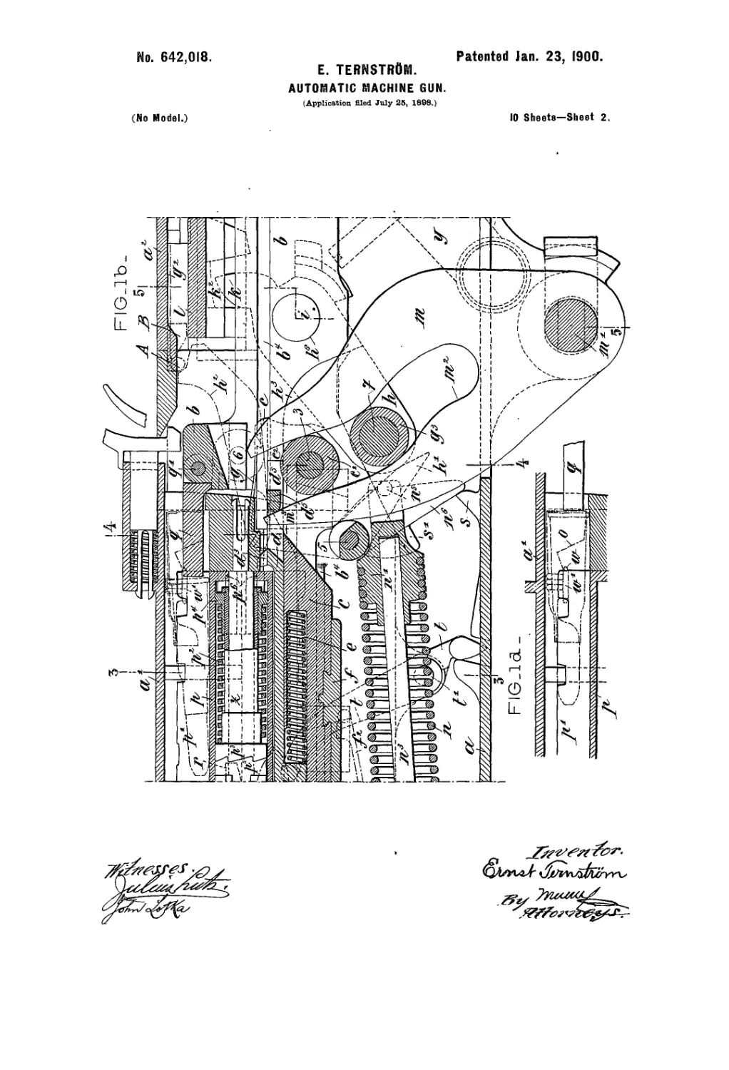
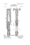
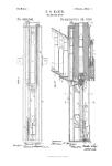
Figures la, 1?, and Iе are portions of a lon-
gitudinal section on the axial line of the en-
gine, showing the mechanism in the firing po-
sition/. Fig. ld is a detail showing a cartridge
before its release with the parts engaging it. <5o
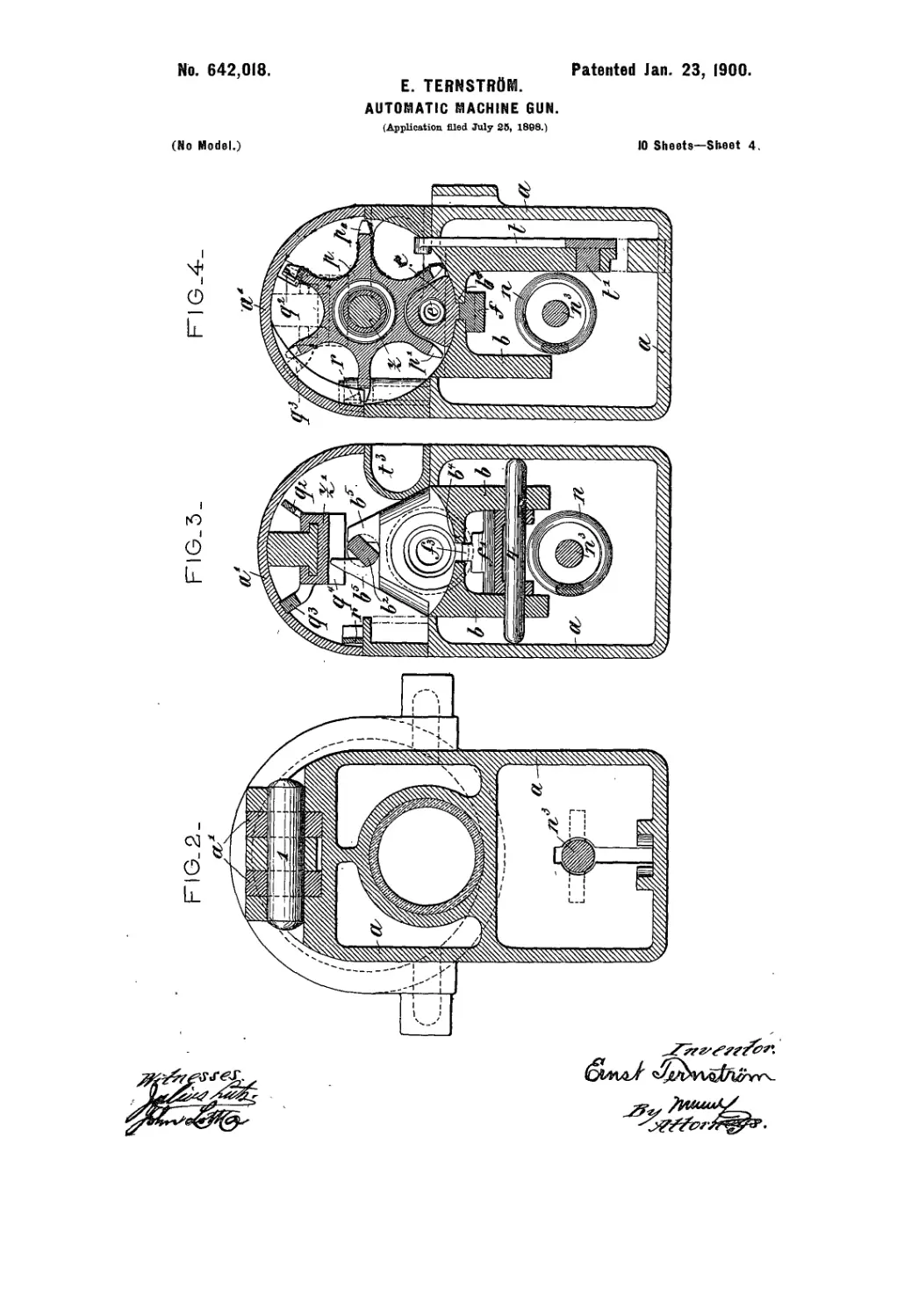
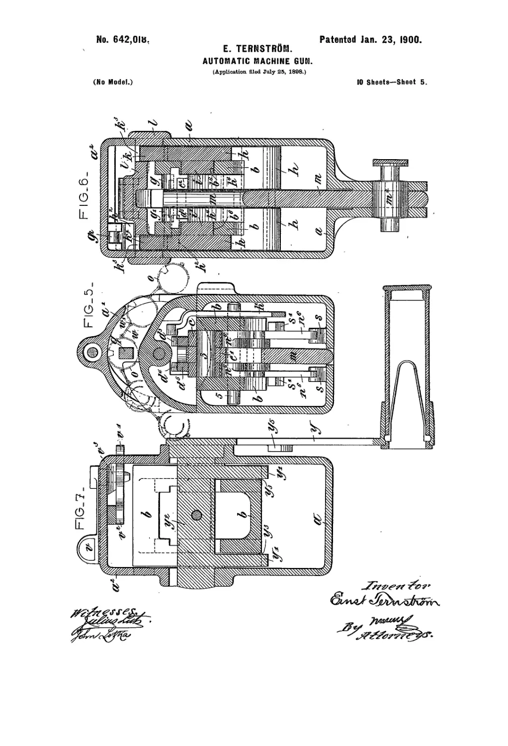
Figs. 2 to 7 are cross-sections on the lines 11,
.2 2,3 3,4 4,5 5, and 6 6, respectively, of the lon-
gitudinal section shown in Figs. la, lb, and Iе.
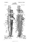
Fig. 8 is a plan view of the back cover. Fig.
9 is a vertical section showing the mechanism 65
in the recoil position with some parts omitted.
Fig. 9a is a side elevation, with parts in sec-
tion, showing the feed mechanism. Figs. 9b
and 9° are detail views, from side and end, of
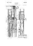
portions of said mechanism. Fig. 10 is a de- 70
tail view, in longitudinal section, of the mov-
able breech-piece. Fig. 11 is a longitudinal
section of the fixed case. Fig. 12 shows in
longitudinal section and in cross-section the
bolt of the movable case. Fig. 13 represents 75
the firing-pin in elevation and also in plan.
Figs. 14 and 15 are respectively an elevation
and a plan of the support for the cartridge- •
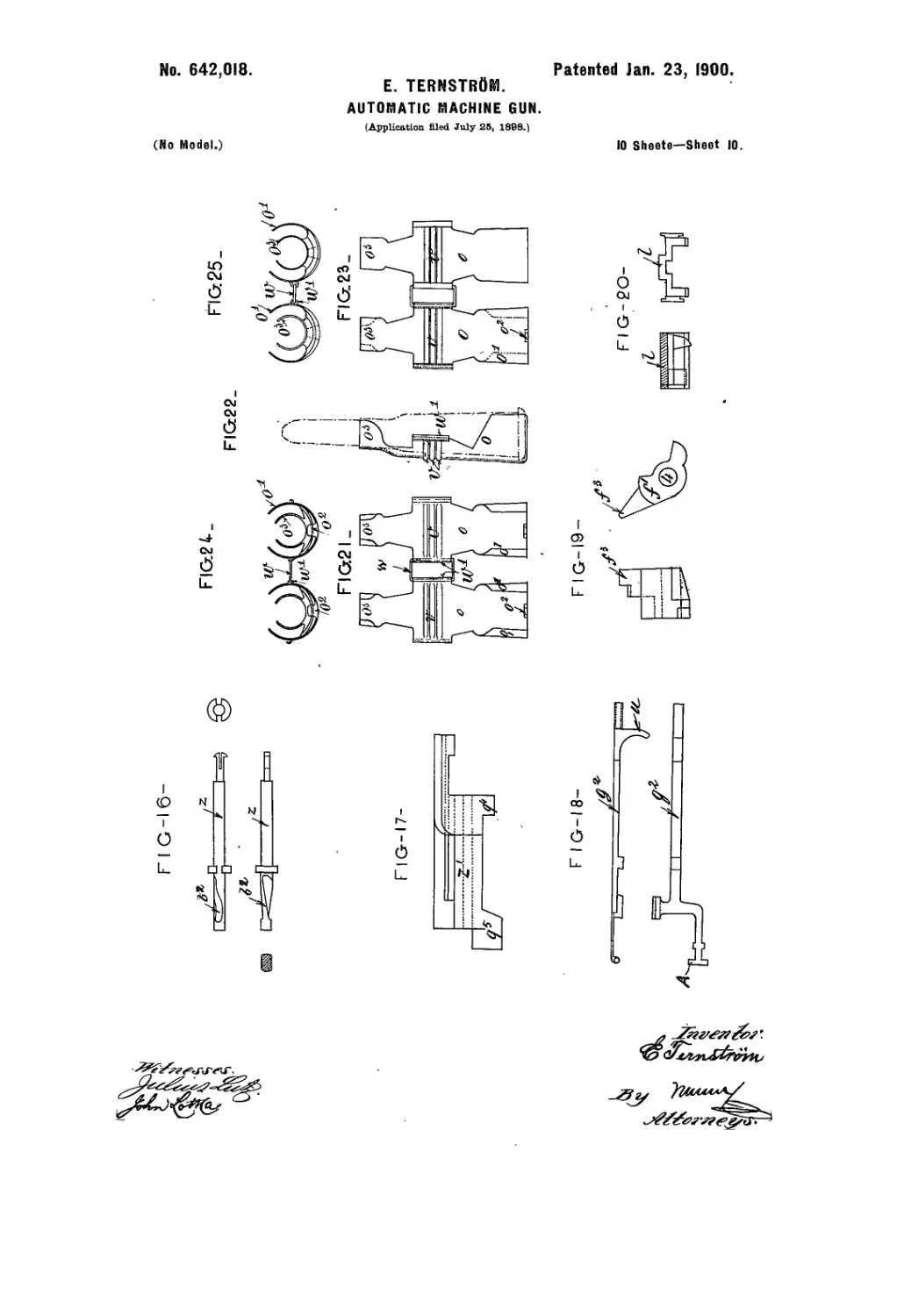
drum. Figs. 16 and 17 show, respectively,
the spindle of the drum and the escapement 80
of the same. Fig. 18 represents the trigger
both in elevation and in plan.' Fig. 19 shows
views of the extractor-locking lever. Fig. 20
represents both in section and in elevation
the resistance-plate whereby oscillation of 85
the locking-levers of the movable breech-bolt
is obtained. Figs. 21 to .25 are views show-
ing two elements of the metallic cartridge-
belt in bottom plan view', in side view, and
inend view, respectively. 90
The improved machine-gun is composed of
two main parts, which are the case, which re-
mains stationary during the firing, and the re-
coil system, which contains the barrel and
the closing and firing mechanism. All the 95
movements of the different pieces are effected
by the reciprocation of the recoil system,
which is produced either by the explosion of
the charge in automatic firing or by the han-
dle when firing by hand. 100
The stationary case.—The whole of the
mechanism is inclosed in the stationary case
a, Figs. la to 7 and Fig. 11, which isprovided
with guideways for the different pieces and
2
642,013
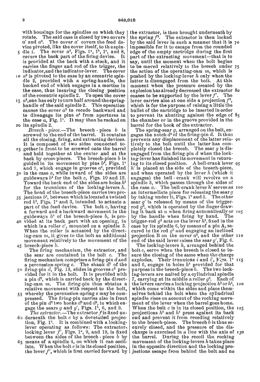
with housings for the spindles on which they |
rotate. The said case is closed by two covers
a! and a2. The cover a' covers the feed de-
vice pivoted, like the cover itself, to th espin-
5 die 1. The cover a2, Figs. la, lb, Iе, and 8,
covers the back part of the firing device. It
is provided at the back with a stock, and it
carries the finger and rod of the trigger, the
indicator,and the indicator-lever. The cover
io a2 is pivoted to the case by an eccentric spin-
dle 2, provided with a spring-handle, the
hooked end of which engages in a mortise in
the case, thus insuring the closing. position
of the eccentric spindle 2. To open the cover
15 a2,one has only to turn half around the spring-
handle of the said spindle 2. This operation
causes the cover a2 to recede backward and
to disengage its pins a4 from apertures in
the case a, Fig. Iе. It may then be rocked on
го its spindle 2.
Breech - piece.—The breech - piece b is
screwed to the end of the barrel. It contains
all the closing, firing, and extracting devices.
It is composed of two sides connected to-
25 getherin front to be screwed onto the barrel
and held together at the center and at the
back by cross-pieces. The breech-piece b is
guidedin' its movement by pins b3, Figs. Iе
and 9, which engage in grooves a3, provided
30 in the case a, while inward of the sides are
guideways b4 for the bolt c, Figs. 10 and 12.
Toward the back end of the sides are holes hs
for the trunnions of the locking-levers h.
The head of the breech-piece carries two pro-
35 jections b5, between which is located a twisted
rod b2, Figs. la and 3, intended to actuate a
part of the feed device. The bolt c, having
a forward and abackward movement in the
guideways b4 of the breech-piece b, is pro-
40 vided at its back part with an opening, in
which is a roller c', mounted on a spindle 3.
When the roller is actuated by the direct-
ing-cam m, it gives to the bolt an additional
movement relatively to the movement of the
45 breech-piece b.
The firing mechanism, the extractor, and
the sear are contained in the bolt c. The
firing mechanism comprises a firing-pin d and
a percussion-spring e. The shank d* of the
50 firing-pin d, Fig. 13, slides in grooves c2 pro-
vided for it in the bolt. It is provided with
a pin d2, which is carried back by the direct-
ing-cam on. The firing-pin thus obtains a
relative movement with respect to the bolt,
55 whereby the percussion-spring e maybe com-
pressed. The firing-pin carries also in front
of the pin d2 two hooks d3 and <74, in which en-
gage the sears g and д', Figs. lb, 6, and 9.
The extractor.—The extractor/is fixed un-
бэ derneath the bolt c by a dovetailed projec-
tion, Fig. lb. It is combined with a locking-
lever operating as.follows: The extractor-
locking lever /', Figs. la, 9, and 19, is fixed
between the sides of the breech - piece b by
65 means of a spindle 4, on which it can oscil-
late. When the bolt c is in its closed position,
the lever/', which is first carried forward by
the extractor, is then brought underneath by
the spring/2. The extractor is then locked
by the said lever in such a manner that it is 70
impossible for it to escape from the rounded
edge of the empty cartridge during the first
part of the extracting movement—that is to
say, until the moment when the bolt begins
to be moved relatively to the breech under 75
the action of the operating-cam m, which is
pushed by the locking-lever h onlj7 when the
latter is disengaged from the bolt. At this
moment when the pressure created by the
explosion has already decreased the extractor 80
ceases to be supported bj7 the lever/'. The
lever carries also at one side a projection/3,
which is for the purpose of raising a little the
bullet of the cartridge to be inserted in order
to prevent its abutting against the edge of 85
the chamber or in the groove provided in the
barrel for the hook of the extractor.
The spring-sear g, arranged on the bolt, en-
gages the notch d3 of the firing-pin d. It thus
prevents any displacement of the latter rela- 90
tively to the bolt until the latter has com-
pletely closed the breech. The sear g is dis-
engaged from the firing-pin d when the lock-
ing-lever has finished its movement in return-
ing to its closed position. A bell-crank lever 95
h' is placed at the side of the breech-piece,
and when operated by the lever h (which it
engages) the bell - crank will revolve on a
spindle 5, which passes through the sides of
the case a.- The bell-crank lever h' serves as 100
an intermediate piece for releasing the sear g
by taking under it, Figs. lb and 5. The other
sear д' is released by means of the trigger-
rod g2, which is operated by the finger draw-
ing it back at и when firing automatically or 105
by the handle when firing by hand. The
trigger-rod g2 acts on the lever Id, fixed in the
case by its spindle 6, by means of a pin A, se-
cured to the rod g2 and engaging an inclined
projection В on the cover a2, and the other no
end of the said lever raises the sear д', Fig. 6.
The locking-levers h, arranged behind the
bolt c, serve wheu the breech is closed to in-
sure the closing of the same when the charge
explodes. Their trunnions i and i', Figs. lb 115
and 6, engage in holes Id provided for that
purpose in the breech-piece b. The two lock-
ing-levers are united by a cylindrical spindle
7, carrying at its middle a roller g3. Each of
the levers carries a locking projection or Id, 120
which come within the sides and place them-
selves behind the bolt when the cylindrical
spindle rises on account of the rocking move-
ment of the lever when the barrel goes home.
When the bolt c is in its closed position, the 125
projections h3 and Id press against its back
end and prevent it from receding relatively
to the breech-piece. The breech b is thus se-
curely closed, and the pressure of the dis-
charge is exercised in a line with the axis of 130
the barrel. During the recoil the rocking
movement of the locking-levers Stakes place
in the opposite direction and the locking pro-
jections escape from behind the bolt and no
642,018
s
IO
15
20
25
3°
35
4°
45
5°
55
60
65
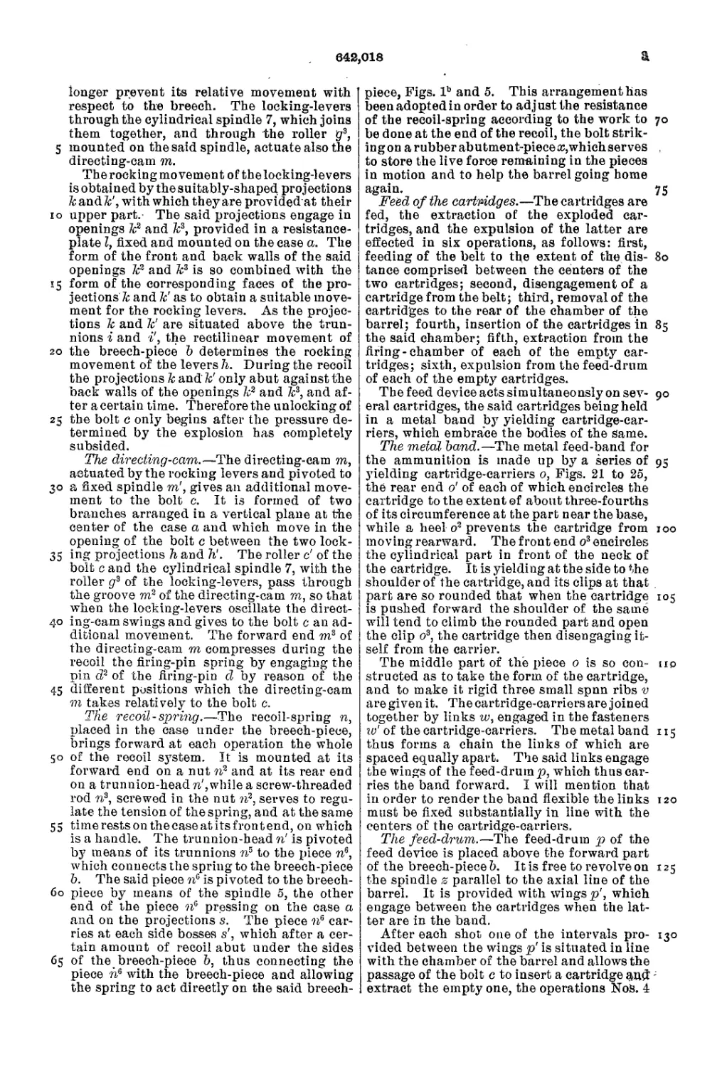
longer prevent its relative movement with
respect to the breech. The locking-levers
through the cylindrical spindle 7, which joins
them together, and through the roller gr3,
mounted on the said spindle, actuate also the
directing-cam m.
The rocking movement of the locking-levers
is obtained by the suitably-shaped projections
ZcandZc', with which they are provided at their
upper part. The said projections engage in
openings Zc2 and k3, provided in a resistance-
plate I, fixed and mounted on the case a. The
form of the front and back walls of the said
openings k2 and k3 is so combined with the
form of the corresponding faces of the pro-
jections к and k' as to obtain a suitable move-
ment for the rocking levers. As the projec-
tions к and k' are situated above the trun-
nions i and i’, the rectilinear movement of
the breech-piece b determines the rocking
movement of the levers h. During the recoil
the projections к andfc' only abut against the
back walls of the openings k2 and k3, and af-
ter a certain time. Therefore the unlocking of
the bolt c only begins after the pressure de-
termined by the explosion has completely
subsided.
The directing-cam.—The directing-cam m,
actuated by the rocking levers and pivoted to
a fixed spindle m', gives an additional move-
ment to the bolt c. It is formed of two
branches arranged in a vertical plane at the
center of the case a and which move in the
opening of the bolt c between the two lock-
ing projections h and h‘. The roller c' of the
bolt c and the cylindrical spindle 7, with the
roller g3 of the locking-levers, pass through
the groove m2 of the directing-cam m, so that
when the locking-levers oscillate the direct-
ing-cam swings and gives to the bolt c an ad-
ditional movement. The forward end m3 of
the directing-cam m compresses during the
recoil the firing-pin spring bjr engaging the
pin d2 of the firing-pin d by reason of the
different positions which the directing-cam
m takes relatively to the bolt c.
The recoil-spring.—The recoil-spring n,
placed in the case under the breech-piece,
brings forward at each operation the whole
of the recoil system. It is mounted at its
forward end on a nut n2 and at its rear end
on a trunnion-head ri, while a screw-threaded
rod n3, screwed in the nut n2, serves to regu-
late the tension of the spring, and at the same
timerestsonthecaseatitsfrontend, on which
is a handle. The trunnion-head ri is pivoted
by means of its trunnions n3 to the piece n3,
which connects the spring to the breech-piece
b. The said piece n3 is pivoted to the breech-
piece by means of the spindle 5, the other
end of the piece n3 pressing on the case a
and on the projections s. The piece n3 car-
ries at each side bosses s', which after a cer-
tain amount of recoil abut under the sides
of the breech-piece b, thus connecting the
piece n3 with the breech-piece and allowing
the spring to act directly on the said breech-
a
piece, Figs. lb and 5. This arrangement has
been adopted in order to adj ust the resistance
of the recoil-spring according to the work to 70
be done at the end of the recoil, the bolt strik-
ingonarubberabutment-pieceo:,whichserves ,
to store the live force remaining in the pieces
in motion and to help the barrel going home
again. 75
Feed of the cartridges.—The cartridges are
fed, the extraction of the exploded car-
tridges, and the expulsion of the latter are
effected in six operations, as follows: first,
feeding of the belt to the extent of the dis- 80
tance comprised between the centers of the
two cartridges; second, disengagement of a
cartridge from the belt; third, removal of the
cartridges to the rear of the chamber of the
barrel; fourth, insertion of the cartridges in 85
the said chamber; fifth, extraction from the
firing-chamber of each of the empty car-
tridges; sixth, expulsion from the feed-drum
of each of the empty cartridges.
The feed device acts simultaneously on sev- 90
eral cartridges, the said cartridges being held
in a metal band by yielding cartridge-car-
riers, which embrace the bodies of the Same.
The metal band.—The metal feed-band for
the ammunition is made up by a series of 95
yielding cartridge-carriers 0, Figs. 21 to 25,
the rear end o' of each of which encircles the
cartridge to the extent of about three-fourths
of its circumference at the part near the base,
while a heel o2 prevents the cartridge from 100
moving rearward. The front end o3 encircles
the cylindrical part in front of the neck of
the cartridge. It is yielding at the side to the
shoulder of the cartridge, and its clips at that .
part are so rounded that when the cartridge 105
is pushed forward the shoulder of the same
will tend to climb the rounded part and open
the clip o3, the cartridge then disengaging it-
self from the carrier.
The middle part of the piece 0 is so con- iic
structed as to take the form of the cartridge,
and to make it rigid three small spun ribs v
are given it. The cartridge-carriers are joined
together by links w, engaged in the fasteners
w' of the cartridge-carriers. The metal band 115
thus forms a chain the links of which are
spaced equally apart. The said links engage
the wings of the feed-drum p, which thus car-
ries the band forward. I will mention that
in order to render the band flexible the links 120
must be fixed substantially in line with the
centers of the cartridge-carriers.
The feed-drum.—The feed-drum p of the
feed device is placed above the forward part
of the breech-piece b. It is free to revolve on 125
the spindle z parallel to the axial line of the
barrel. It is provided with wings p', which
engage between the cartridges when the lat-
ter are in the band.
After each shot one of the intervals pro- 130
vided between the wings p' is situated in line
with the chamber of the barrel and allows the
passage of the bolt c to insert a cartridge -
extract the empty one, the operations NoS. 4
4
&afi,O18
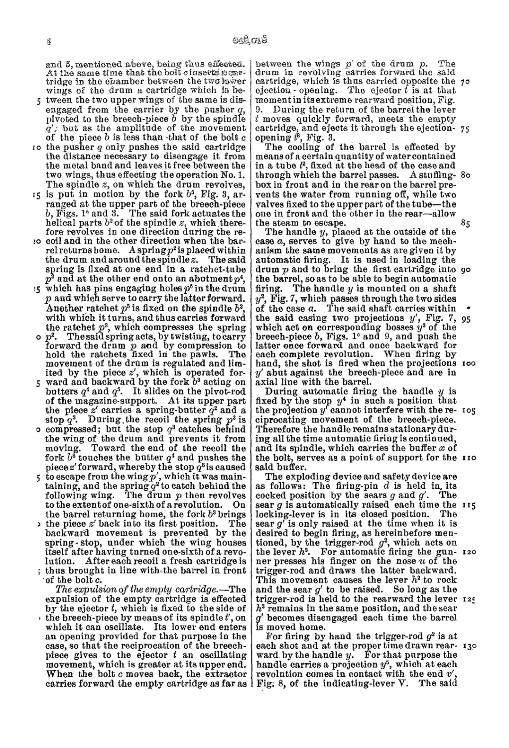
and 5. mentioned, above, being thus effected.
At the same time that the bolt cinsartdaoar-
tridge in the chamber between the two tower
wings of the drum a cartridge which is be-
5 tween the two upper wings of the same is dis-
engaged from the carrier by the pusher q,
pivoted to the breech-piece b by the spindle
q'j but as the amplitude of the movement
of the piece b is less than -that of the bolt c
io the pusher q only pushes the said cartridge
the distance necessary to disengage it from
the metal band and leaves it free between the
two wings, thus effecting the operation No. 1.
The spindle z, on which the drum revolves,
15 is put in motion by the fork bs, Fig. 3, ar-
ranged at the upper part of the breech-piece
b, Figs. la and 3. The said fork actuates the
helical parts b2of the spindle z, which there-
fore revolves in one direction during the re-
:o coil and in the other direction when the bar-
rel returns home. A spring^2 is placed within
the drum and around the spindle z. The said
spring is fixed at one end in a ratehet-tube
p3 and at the other end onto an abutment^/,
15 which has pins engaging holes p9 in the drum
p and which serve to carry the latter forward.
Another ratchet p5 is fixed on the spindle b2,
with which it turns, and thus carries forward
the ratchet p3, which compresses the spring
о p2. The said spring acts, by twisting, to carry
forward the drum p and by compression to
hold the ratchets fixed in the pawls. The
movement of the drum is regulated and lim-
ited by the piece z', which is operated for-
5 ward and backward by the fork b3 acting on
butters qi and qs. It slides on the pivot-rod
of the magazine-support. At its upper part
the piece z' carries a spring-butter q2 and a
stop q3. During, the recoil the spring p2 is
0 compressed; but the stop q3 catches behind
the wing of the drum and prevents it from
moving. Toward the end of the recoil the
fork b3 touches the butter qi and pushes the
pieces' forward, whereby the stop qsis caused
5 to escape from the wingp', which it was main-
taining, and the spring q2 to catch behind the
following wing. The drum p then revolves
to the extent of one-sixth of a revolution. On
the barrel returning home, the fork b3 brings
> the piece z' back into its first position. The
backward movement is prevented by the
spring-stop, under which the wing houses
itself after having turned one-sixth of a revo-
lution. After each recoil a fresh cartridge is
i thus brought in line with the barrel in front
of the bolt c.
The expulsion of the empty cartridge.—The
expulsion of the empty cartridge is effected
by the ejector t, which is fixed to the side of
1 the breech-piece by means of its spindle t’, on
which it can oscillate. Its lower end enters
an opening provided for that purpose in the
case, so that the reciprocation of the breech-
piece gives to the ejector t an oscillating
movement, which is greater at its upper end.
When the bolt c moves back, the extractor
carries forward the empty cartridge as far as
between the wings p of the drum p. The
drum in revolving carries forward the said
cartridge, which is thus carried opposite the 70
ejection - opening. The ejector t is at that
moment in its extreme rearward position, Fig.
9. During the return of the barrel the lever
t moves quickly forward, meets the empty
cartridge, and ejects it through the ejection- 75
opening t3, Fig. 3.
The cooling of the barrel is effected by
means of a certain quantity of water contained
in a tube t2, fixed at the head of the case and
through which the barrel passes. A stuffing- 80
box in front and in the rear on the barrel pre-
vents the water from running off, while two
valves fixed to the upper part of the tube—the
one in front and the other in the rear—allow
the steam to escape. 85
The handle y, placed at the outside of the
case a, serves to give by hand to the mech-
anism the same movements as are given it by
automatic firing. It is used in loading the
drum p and to bring the first cartridge into 90
the barrel, so as to be able to begin automatic
firing. The handle у is mounted on a shaft
y2, Fig. 7, which passes through the two sides
of the case a. The said shaft carries within •
the said casing two projections y', Fig. 7, 95
which act on corresponding bosses y3 of the
breech-piece b, Figs. Iе and 9, and push the
latter once forward and once backward for
each complete revolution. When firing by
hand, the shot is fired when the projections 100
y' abut against the breech-piece and are in
axial line with the barrel.
During automatic firing the handle у is
fixed by the stop y* in such a position that
the projection y' cannot interfere with the re- 105
ciprocating movement of the breech-piece.
Therefore the handle remains stationary dur-
ing all the time automatic firing is continued,
and its spindle, which carries the buffer x ot
the bolt, serves as a point of support for the no
said buffer.
The exploding device and safety device are
as follows: The firing-pin d is held in. its
cocked position by the sears g and д'. The
sear g is automatically raised each time the 115
locking-lever is in its closed position. The
sear д' is only raised at the time when it is
desired to begin firing, as hereinbefore men-
tioned, by the trigger-rod g2, which acts on
the lever h2. For automatic firing the gun- 120
ner presses his finger on the nose и of the
trigger-rod and draws the latter backward.
This movement causes the lever h2 to rock
and the sear д' to be raised. So long as the
trigger-rod is held to the rearward the lever 12;
h2 remains in the same position, and the sear
д' becomes disengaged each time the barrel
is moved home.
For firing by hand the trigger-rod g2 is at
each shot and at the proper time drawn rear- 130
ward by the handle y. For that purpose the
handle carries a projection y3, which at each
revolntion comes in contact with the end v',
Fig; 8, of the indicating-lever V. The said
642,018
5
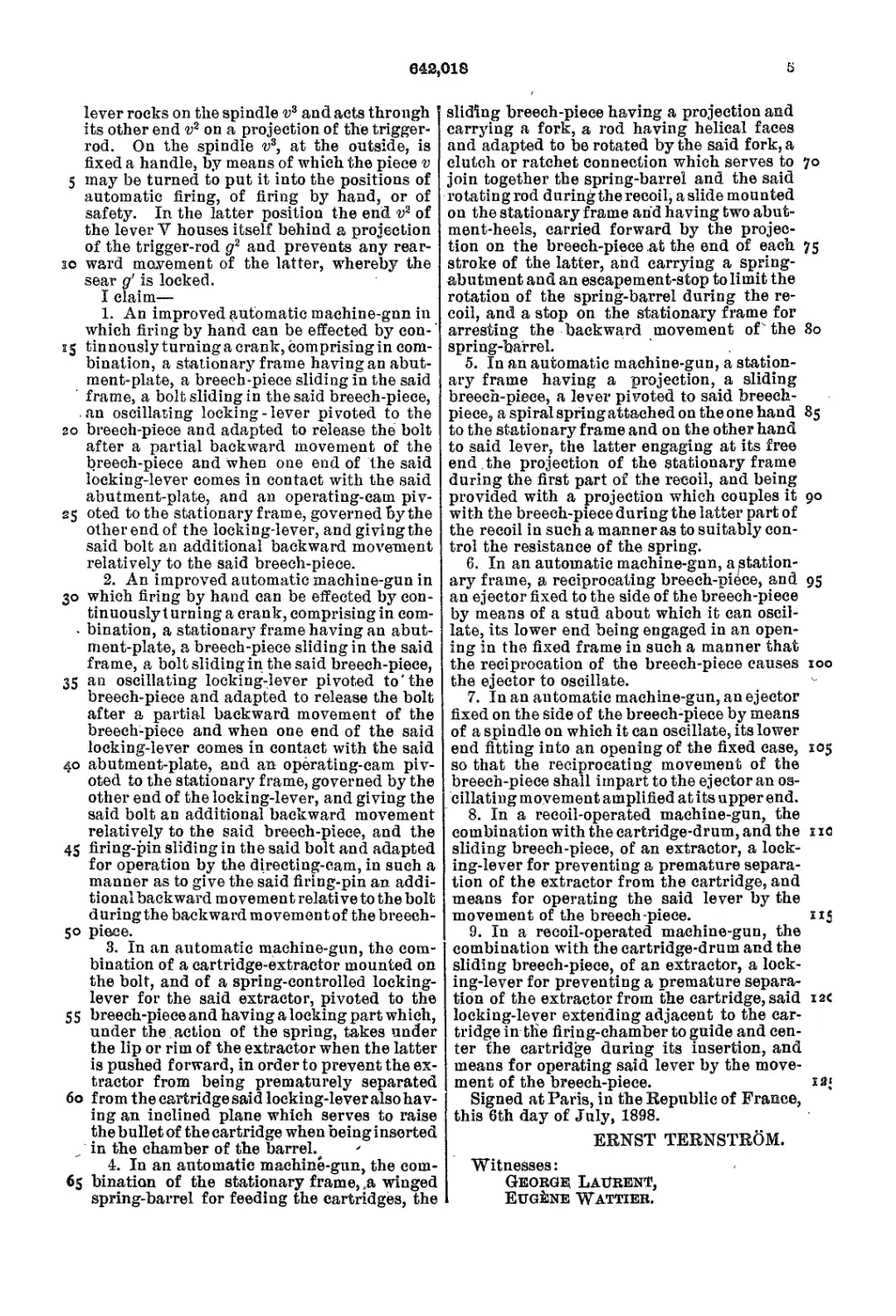
lever rocks on the spindle v3 and acts through
its other end v2 on a projection of the trigger-
rod. On the spindle v3, at the outside, is
fixed a handle, by means of which the piece v
5 may be turned to put it into the positions of
automatic firing, of firing by hand, or of
safety. In the latter position the end v2 of
the lever V houses itself behind a projection
of the trigger-rod g2 and prevents any rear-
io ward movement of the latter, whereby the
sear д' is locked.
I claim—
1. An improved automatic machine-gnn in
which firing by hand can be effected by con-'
15 tinnously turning a crank, comprising in com-
bination, a stationary frame having an abut-
ment-plate, a breech-piece sliding in the said
frame, a bolt sliding in the said breech-piece,
an oscillating locking - lever pivoted to the
20 breech-piece and adapted to release the bolt
after a partial backward movement of the
breech-piece and when one end of the said
locking-lever comes in contact with the said
abutment-plate, and an operating-cam piv-
25 oted to the stationary frame, governed by the
other end of the locking-lever, and giving the
said bolt an additional backward movement
relatively to the said breech-piece.
2. An improved automatic machine-gun in
30 which firing by hand can be effected by con-
tinuously t urning a crank, comprising in com-
- bination, a stationary frame having an abut-
ment-plate, a breech-piece sliding in the said
frame, a bolt sliding in the said breech-piece,
35 an oscillating locking-lever pivoted to'the
breech-piece and adapted to release the bolt
after a partial backward movement of the
breech-piece and when one end of the said
locking-lever comes in contact with the said
40 abutment-plate, and an operating-cam piv-
oted to the stationary frame, governed by the
other end of the locking-lever, and giving the
said bolt an additional backward movement
relatively to the said breech-piece, and the
45 firing-pin sliding in the said bolt and adapted
for operation by the directing-cam, in such a
manner as to give the said firing-pin an addi-
tional backward movement relative to the bolt
during the backward movemen t of the breech-
50 piece.
3. In an automatic machine-gun, the com-
bination of a cartridge-extractor mounted on
the bolt, and of a spring-controlled locking-
lever for the said extractor, pivoted to the
5 5 breech-piece and having a locking part wh ich,
under the . action of the spring, takes under
the lip or rim of the extractor when the latter
is pushed forward, in order to prevent the ex-
tractor from being prematurely separated
60 from the cartridge said locking-lever also hav-
ing an inclined plane which serves to raise
the bullet of the cartridge when being inserted
in the chamber of the barrel.,
4. In an automatic machine-gun, the com-
65 bination of the stationary frame, .a winged
spring-barrel for feeding the cartridges, the
sliding breech-piece having a projection and
carrying a fork, a rod having helical faces
and adapted to be rotated by the said fork, a
clutch or ratchet connection which serves to 70
join together the spring-barrel and the said
rotating rod duringthe recoil, a slide mounted
on the stationary frame and having two abut-
ment-heels, carried forward by the projec-
tion on the breech-piece at the end of each 75
stroke of the latter, and carrying a spring-
abutment and an eseapement-stop to limit the
rotation of the spring-barrel during the re-
coil, and a stop on the stationary frame for
arresting the backward movement of the 80
spring-barrel.
5. In an automatic machine-gun, a station-
ary frame having a projection, a sliding
breech-piece, a lever pivoted to said breech-
piece, a spiral spring attached on the one hand 85
to the stationary frame and on the other hand
to said lever, the latter engaging at its free
end .the projection of the stationary frame
during the first part of the recoil, and being
provided with a projection which couples it 90
with the breech-piece during the latter part of
the recoil in such a manner as to suitably con-
trol the resistance of the spring.
6. In an automatic machine-gnn, a station-
ary frame, a reciprocating breech-piece, and 95
an ejector fixed to the side of the breech-piece
by means of a stud about which it can oscil-
late, its lower end being engaged in an open-
ing in the fixed frame in such a manner that
the reciprocation of the breech-piece causes 100
the ejector to oscillate.
7. In an automatic machine-gun, an ejector
fixed on the side of the breech-piece by means
of a spindle on which it can oscillate, its lower
end fitting into an opening of the fixed case, X05
so that the reciprocating movement of the
breech-piece shall impart to the ejector an os-
cillating movement amplified at its upper end.
8. In a recoil-operated machine-gun, the
combination with the cartridge-drum, and the tl ic
sliding breech-piece, of an extractor, a lock-
ing-lever for preventing a premature separa-
tion of the extractor from the cartridge, and
means for operating the said lever by the
movement of the breech-piece. 215
9. In a recoil-operated machine-gun, the
combination with the cartridge-drum and the
sliding breech-piece, of an extractor, a lock-
ing-lever for preventing a premature separa-
tion of the extractor from the cartridge, said 12c
locking-lever extending adjacent to the car-
tridge in the firing-chamber to guide and cen-
ter the cartridge during its insertion, and
means for operating said lever by the move-
ment of the breech-piece. x 2‘
Signed at Paris, in the Republic of France,
this 6th day of July, 1898.
ERNST TERNSTROM.
Witnesses:
Georg® Laurent,
Eugene Wattier.