/


Tags: weapons military affairs machine gun patent
Year: 1903

Text
Но. 723,232.
PATENTED MAR. 24, 1903.
. T. BERGMANN.
AUTOMATIC MACHINE GUN.
APPLICATION PILED SEPT. 26, 1901.
ЛО MODEL.
6 SHEETS—SHEET 1.
No. 723,232. ..PATENTED MAR. 24, 1903.
T. BERGMANN.
AUTOMATIC MACHINE GUN.
APPLICATION PILED SEPT. 26, 1901.
NO MODEL. 5 SHEETS—SHEET 2
No. 723,232.
PATENTED MAR. 24, 1903.
T. BERGMANN.
AUTOMATIC MACHINE GUN.
APPLICATION PILED SEPT. 26, 1901.
NO MODEL.
5 SHEETS-SHEET 3.
No. 723,232. PATENTED MAR. 24, 1903.
. T. BERGMANN.
AUTOMATIC MACHINE GUN.
APPLICATION PILED SEPT. 26. 1901.
5 SHEETS-SHEET 4.
NO MODEL.
—Ttz-x/etz-L o R ,
No. 723,232.
PATENTED MAR. 24, 1903.
T. BERGMANN.
AUTOMATIC MACHINE GUN.
APPLICATION PILED SEPT. 26, 1901.
NO MODEL.
5 SHEETS—SHEET 5.
United States Patent Office.
THEODOR BERGMANN, OF BADEN, GERMANY.
AUTOMATIC MACHINE-GUN.
SPECIFICATION forming' part of betters Patent No. 723,232, dated March 24, 1903.
Application-filed September 26,1801. Serial Mo, 76,6004 (No model.)
To all whom it may concern:
Be it known that I, Theodor Bergmann, a
subject of the Emperorof Germany, residing
at Baden, Germany, have invented certain
5 new and useful Improvements in and Relat-
ing to Automatic Machine-Guns, of which the
following is a specification.
My invention relates to automatic machine-
guns, and is chiefly designed to simplify the
io construction and increase the efficiency of
such firearms.
An important feature of my said invention
consists in an improved locking piece or
wedgefor automatically securing the breech-
15 bolt in its closed position at the proper times
during the forward-and-backward motion of
the barrel in the operation of the gun, which
locking-piece can be employed as well for an
infantry recoil-loading gnn as for a so-called
го “machine-gun.” The said locking piece or
wedge is arranged so as to slide in a trans-
verse slot in a guide-sleeve secured to and
moving with the. barrel and is formed with
an aperture or passage through which the
25 breech-bolt passes, the transverse motion of
the said wedge or locking-piece in its slot in
locking the breech-bolt to the said sleeve and
in releasing it therefrom being obtained by
means of inclined surfaces on the said wedge
30 engaging with corresponding inclined planes
on the casing of the gun or on the casing of
the gun and on the breech-bolt.
According to another part of my said in-
vention I provide a pivoted lever, which may
35 be termed a “ firing-pin holder,” and prevents’
the firing-pin from being moved forward to:
fire the cartridge except at such times when
the breech-bolt is locked to the said sleeve,
the said lever also serving to retain the firing-
40 pin in position in the breech-bolt.
My said invention also relates to an im-
proved construction, to be hereinafter de-
scribed, whereby the main operative parts of
the gun move rectilinearly, so as to simplify
45 the.construction and prevent forces being set
up tending to interfere with the steadiness of
the aim. .
In the accompanying drawings I have
shown how wy Said invention can be con-
50 veniently and advantageously carried into
practice. ;
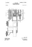
Figure 1 is a vertical longitudinal section
through the rear part of a machine-gun with
the breech closed; Fig. 2, a horizontal.longi-
tudinal section of the same gun with 'the 55
breech open; Fig. 3, a transverse section on
the line C D, Fig. 2, seen from the front and;
with the rearward parts made visible. Fig. 4
is a rear elevation of the gun. Fig. a ish
transverse section on the line E F, Fig. 2, look- 6o
ing toward the front. Fig. 6 is a transverse
section on the line A B, Fig.' 1, looking to-
ward the rear. Fig. 7 is a vertical longitudi-
nal section of the same gun with the breech-
bolt moved back and the lock cocked. Fig.Sis 65
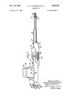
an elevation of the whole gun, drawn to a re-
duced scale, seen from the left. Fig. 9 is an
elevation, of similar size, of the same gun
seen front above. Fig. 10 shows the breech-
bolt seen from the left, with the extractor. '70
Fig. 11 shows the firing-pin holder in two
views.1. Fig. 12 is a vertical longitudinal sec-
tion. Of the casing and breech-bolt in the
neighborhood of the locking wedge or block
in another fiiodification of the latter. ' 75
Like reference characters indicate corre-
sponding parts throughout the drawings.
The barrel 1 is screwed into a guide sleeve
or frairie 2, which slides in the tubular cas-
ing 3 of the gun. The breech-bolt 4, which 8c
slfdes in the aleeVe 2, bears externally an ex-
tractor 5 and is provided with an internal
passage or bore in Which slides the firing-pin
6. The said dring-pin is pressed rearward by
a spring 8 and is detained within the said 85
breech-bolt by a firing-pin holder 7. A lock-
j ingpiece or wedge 9 is mounted so as to slide
(transversely in the sleeve 2 and is formed
i with a rectangnlak* passage, through which
I the front angdlar part of the breech-bolt 4 90
;can pass. The casing 3 is, moreover, pro-
i vided at a suitable position with a groove 3",
into which the locking-wedge 9 can pass in
order to move out of engagement with the
breech-bolt 4, and the said breech-bolt has a 95
locking-groove 4", with which the locking
piece of wedge 9 can interlock. The locking-
piece can also be made in a somewhat differ-
ent manner to that shown in the drawings,
and according to this only the corresponding 100
grooves are to be formed.
The firing-pin holder 7, which prevents the '
firing-pin 6, acted upon by its spring 8, from
moving rearward out of the breechrbolt 4, also
2
7.33,333'
forms a safety device, whereby no firing'of
the cartridge can take place unless the breech-
bolt 4 has previously been locked to the sleeve
2. For this purpose the point of the firing-
5 pin can only be moved up to the percussion-
cap when the front end of the firing-pin
holder, which moves beneath the upper part
of ths locking - piece 9, can move upward.
Thus if the locking-piece 9 is not in its upper
io locked position the firing-pin holder 7, swing-
ing about its pin, cannot move upward at its
front end, and the middle part of the firing-
pin holder, which passes through the firing-
pin 6, prevents the forward motion thereof,
15 and consequently also the firing.
On. the upper part of the casing 8 is mount-
ed a guide-sleeve 16 for a striker 17, the flat
arm cf which extends through the' slotted
tubes 16. 3, and 2 into the interior far enough
20 for the firing-pin 6 to bestruck thereby. The
striker 17 extends rearward in the form of a
round rod, in which the notch for the trigger
is cut, and is driven 'forward by a spring IS,
which bears at its rear end against a stop in
25 the bore of the sleeve 16.
At the lower part of the casing 3 is mount-
ed a sleeve 19, in which the cocking-piece 20
slides. This cocking-piece, in the same man-
ner as the striker 17, has a fiat arm extending
30 into the casing and engaging in a correspond-
ing recess in the breech-bolt 4, so as io couple
the cocking-piece 20 with the breech-bolt 4 in
such a manner that both parts must move to-
gether.
35 Behind the cocking-piece 20 in the sleeve
19 is arranged the closing-spring 21, which
bears at the rear against a stop in the sleeve
19. The cocking-piece 20 is bored through in
its cylindrical part, so that a setting-rod 22,
40 which is surrounded by the spring 21, can
pass through. The rod 22 is formed with a
head at its front end to engage with the front
part of the cocking-piece 20 and is provided
with two annular turned notches into which
45 the sear-bolt 29 can enter when the said rod
is in its foremost or rearmost position, respec-
tively. At the rear end the rod 22 bears a
ring 23 to enable it to be conveniently grasped.
The casing-tube 3 is closed at its rear end
50 by the base-screw 24, which limits the rear-
ward travel of the breech-bolt and also of the
sleeve 2, bearing the barrel. To this base-
screw 24 is also rigidly connected the base-
plate 25 through the screws 26 and 27. The
55 base-plate 25 is provided at both its right and
left hand sides with arms between which are
secured two tu rned handles 38 and 39, of wood,
horn, &c., by means of screws 40 and 41, ex-
tending through them. These handles serve
60 for the manipulation of the machine-gun.
As ea,n be seen from Fig. 5, the two sleeves
16 and 19, which are mounted in correspond-
ing seats in the casing 3, are held fast on the
casing 3 by a clamp 34, while displacement
65 of the said sleeves is prevented in a rearward
direction by their abutting against the baa$- I
plate 25 and in a. forward direction by abut- 1
ting against the shouldered or stepped end of
the seats in ths casing 3. The clamp 34 bears
at its lower end the yoke 35, which turns by 70
means of hinges about the pin 36 and is se-
cured by a bolt 37, the handle or knob of
which is visible in Figs. 8 and 9 and which is
prevented from coming loose of itself by a
spring-catch. 75
The ejector 32, Fig. 2, which is mounted in
a groove in the easing 3 and is secured by
means of the pin 33, has its nose projecting
into the breech-bolt 4, which is provided- for
this purpose with a corresponding longitudi- 80
nal groove, as can be seen from Figs. 2, 3,
and 5. In the casing-sleeve 3 is also mounted
the detent-lever 13, which oscillates about
the pin 14, and the longer rearwardly-extend-
ing end of which is continually forced np- 85
ward by the spring 15.
For the protection and cooling of the barrel
1 a cool!ng-jacket 42 is screwed onto the front
end of the easing 3, this jacket bearing the
foresight. The said cooling-jacket, which 90
can be unscrewed by hand, is secured in its
proper position by a jacket-holder in the form
of a pivoted lever 10, which oscillates aboht
a pin 11 on the casing 3 and is actuated by a
spring 12, arranged in a recess in the press- 95
knob of the jacket-holder. The form of this
jacket-holder 10 and its engagement with the
jacket 42 can be seen from Figs. 1, 3,7, and 9.
The movement of thebarrel 1 with the breech-
sleeve 2 is limited forward by a stop-ring 31, re
which is screwed into the cooling-jacket 42.
In order to prevent the water in the cooling-
jacket 42 from running out backward, a joint-
43 is made, with suitable packing material,
in front of the breech-sleeve 2. A similar tc
packed joint is arranged at the muzzle. As-
showb in Figs. 8 and 9, the water can be in-
troduced into or run out of the cooling-jacket
after the removal of a screw-plug attached to
a chain. A valve, which is not shown, per- 1
mits the escape of the steam when the pres-
sure exceeds a predetermined limit. The eye
shown in Fig. 8 and arranged beneath at the
front end of the jacket permits connection of
the gun with a gun-carriage or other object, t
The back sight is not shown and can be the
same as on the infantry weapon with the car-
tridges of which the machine-gun is arranged
to work. Likewise the safety device is not
specially shown and the arrangement which r
permits the firing of single shots, while both
of these facilities can be very efficiently pro-
vided for and carried out. The feeding of
the cartridges is likewise not shown, and
takes place from the right hand and the 1
ejection to the left hand. It can, however, be
effected at any desired side, suitable pas-
sages being formed for this purpose 5n the
casing 3 and sleeve 2, as shown in Figs. 2, 3,
and 7.
Fig. 9 shows on the right-hand side at the
top the passage through which the cartridges
are fed in, preferably on sheet-metal strips.
Operation without cartridges: If the set-
733,332 3
ting-rod 22 is drawn back by the ring 23, the
head of the rod 22 moves back the cocking-
pieee 20 and the breech-bolt 4, coupled there-
to. At the same time the breech-bolt 4 also
5 carries back the barrel 1, together with the
sleeve 2, which is locked to the breech-bolt 4
by the locking-piece 9. As soon as in the
rearward motion of the parts the locking-
piece 9 reaches the position 3n the sleeve 2
io will be simultaneously brought to rest by the
engagement of its rear end with the base-
screw 24. Since the rearward travel of the
sleeve 2 and barrel 1 is limited here, the
b^eech-bolt 4 will continue its rearward mo-
15 tion by the force exerted thereon, and the
locking-piece 9 will be forced out of the locked
position by the interaction of the inclined
locking-surfaces on the said locking-piece 9
and on the breech-bolt 4. If now the breech-
20 bolt is drawn farther back by means of the
rod 22 and the cocking-piece, it will carry
back the striker 17 at the same time, so that
the striker-spring 18 and the closing-spring 21
will be compressed together. As soon as the
25 pull has continued so far that the rear end of
the breech-bolt abuts against the base-screw
the cocking-notch of the striker 17 is brought
opposite thesear28of the trigger,and,pressed
by the spring 30, the said sear springs into the
30 cocking-notch of the striker and holds the lat-
ter fast. At the same time the rear end of the
detent-lever 13, acted upon by its spring 15, is
also rapidly moved upward and places itself
against the front surface of the striker 17,
35 Fig. 7. The sear 29, pressed by the spring
30, simultaneously engages with the inner
notch in the setting-rod 22 and holds the whole
in the open rearmost position. If now the
sear 29 is released by pressing against the
40 end thereof in front of the base-plate 25, the
setting-rod 22 will be free and be driven for-
ward, together with the breech-bolt, by the
spring 21, while the striker 17 will remain in
its cocked position. As soon as the breech-
45 bolt has moved forward so far that its front
surface strikes against the rear end of the
barrel and the locking-piece 9 has its lock-
ing-surface opposite the locking-surface 4° in
the breech-bolt 4 the locking-piece 9, by means
50 of the inclined surface on its under side,'
slides upward on the inclined-plane surface
of the recess 3n in the casing and locks itself
with the breech-block, and then the two parts
move forward together under the action of
55 the spring 21 over the remaining short part
of the travel until the sleeve 2 strikes against
the stop-ring 31 on the cooling-jacket. Thp
locking thus takes place under control. In
the last stage of the forward travel of the
60 sleeve 2 an inclined surface ~on the sleeve 2
strikes against aninc.lined surface on the de-
tent-lever 13, so that the rear arm of the said
lever/ which previously had the position
shown in Fig. 7, takes up the position shown
65 in Fig. 1 and allows the Striker 17 to move
' rapidly forward as soon as the sear 28 at the
rear has been pressed down and Has thus re-
leased the notch of the striker 17.
In firing the operations take place in a some-
what different manner. If a magazine, or 70
band-like strip with loaded cartridges is ap-
plied and the drawn-back cocking-piece 20 is
released in the manner above described, the
breech-bolt 4 will take the first cartridge
from the magazine and push it into the car- 75
tridge-chamber of the barrel, in which opera-
tion the extractor claw or hook slides over the
edge of the base of the cartridge, engages in
the channel or groove thereof, and the gun is
ready for firing. If now the trigger 28 is 80
pressed down, the striker 17, driven by the
striker-spring 18, flies forward and strikes
against the firing-pin 6, the point of which
fires the cartridge. The recoil of the shot
throws the barrel 1, together with the sleeve 85
2 and the breeeh-bolt4, locked thereto, back-
ward, and as the sleeve 2 strikes against the
base-screw 24, and is thus prevented from
moving farther back, the locking-piece 9 un-
locks the breech-bolt 4 in the manner above 90
described,and thus allows the said breech-bolt
to continue its travel and to move rearward
up to the base-screw 24. In this operation the
breech-bolt 4 carries back the striker 17, as
well as the cocking-piece 20. The striker and 95
closing springs 18 and 21 are meanwhile com-
pressed, and the detent-lever 13 places itself
in front of the striker 17 and holds the latter
in its cocked position. The cartridge-case in
this rearward motion is now struck on the 100
right-hand side by the nose of the ejector 32,
and since it is held on the left-hand side by
the extractor-claw it is ejected to the left hand
through the openings in the casing 3.and in
the sleeve 2. The setting-rod 22 during this 105
rearward motion of the other parts remains
in its forward position, Fig. 7. ‘ If now the
pressure on the trigger 28 be continued, the
breech-bolt, acted upon by the closing-spring
21 through the cocking-piece 20, immediately, rio
flies forward again, and thus takes the next
cartridge out of the magazine into the barrel.
Locking of the breech-bolt then takes place,
and at the last moment the detent-lever 13 is
released. The striker, which is held there- 115
by, flies forward against the firing-pin, and
the next shot is fired, and the firing proceeds
continuously until the last cartridge in the
magazine has been fired.
Fig. 12 shows another form of construction, 120
wherein the locking-wedge 9 is arranged so
as to engage with an inclined surface in the
breech-bolt, and be thus unlocked. For this
purpose the inclined surface 3a of a projec-
tion extending into the sleeve 2 strikes against 125
the upwardly-inclined surface 9a on the lock-
ing-wedge-in the rearward travel of the parts
of the breech mechanism, and the locking-
wedge is thereby forced out of the locked, po-
sition. The method of operation of the parts 130
relatively to each other remains the same in
other respects.
728,йЗЭ
What I claim is—
1. : The combination of three: members the
first and second of which have conjoint move-
ment and also a movement the first independ-
5 ently of the second in substantially the same
direction, and the third of which is relatively
stationary, and an interlocking device for
said first and second members movable there-
with and also substantially transversely there-
io of rectili nearly to effect the unlocking there-
of, said third member having an abutment ad-
' jacent the limit of movement of said second
member adapted to lie engaged by said lock-
ing device so as to lock the second and third
15 members together upon the unlocking of said
. first and second members, substantially as
described.
2. The combination of a substantially tu-
bular casing having a recess, the barrel, a
so sleeve movable with said barrel within said
casing, the breech-bolt inclosed in said sleeve
and movable therein, means for limiting the
movement of said sleeve and barrel, means
for moving the breech-bolt longitudinally,
25 and a-locking device adapted to interlock said
breech-bolt and sleeve and movable relatively
thereto rectilinearly to unlock them, said cas-
ing, being adapted to maintain said device in
locking engagement with the breech-bolt and
30 sleeve, and said recess being adapted, to re-
ceive said device when moved to unlock said
breech-bolt and sleeve, substantially as de-
scribed.
3. The combination of a tabular structure,
35 a breech-bolt arranged in said structure, the
one being movable relatively to the other lon-
gitudinally, a firing-pin in said breech-bolt, a
firing-pin holderfulcrumed in the breech-bolt
and engaging the firing-pin to control the po-
40 sition thereof, and a transversely-movable
part in said structure controlling the position
of said holder, said breech-bolt and said part
having engageable an rfaees one of which is i n-
clined, said part being movable upon the rela-
45 tive movement between said structure and the
breech-bolt, substantially as described.
4. The combination of a tubular structure,
a breech-bolt movable in said tubular struc-
ture longitudinally thereof, a locking device
50 for interlockingsaid breech-bolt and tubular
structureand movable transversely thereof to
unlock the same, said tubular structure being
also longitudinally movable, a firing-pin in
said breech-bolt, and a holding device con-
55 trolling the firing-pin arranged in said breech-
bolt, said holding device being adapted to en-
gage said locking device to be thereby actu-
ated, and said locking device and said breech-
bolt having engageable surfaces one of which
is inclined, substantially as described. 60
5. In aa automatic machine-gun, the com-
bination of a casing-sleeve and base-plate hav-
ing longitudinal seats, guide-tubes for the
striker and cocking-piece fi tted in to said seats,
and a chimb provided with a swinging yoke 65
for securing the said guide-tubes in the said
seats, substantially as, and for the purpose,
specified.
6. The combination, in an automatic ma-
chine-gun, of a casing, a guide sleeve or frame 70
to which the barrel is secured, a locking-piece
sliding transversely in said sleeve or frame, a
breech-bolt sliding in said sleeve or frame and
extending through said locking-piece, sur-
faces on said locking-piece coacting with sur- 75
faces on the casing and on the breech-bolt, a
firing-pin in said breech-bolt, and a lever piv-
otally mounted in said breech-bolt and engag-
ing with said firing-pin and said locking-piece,
substantially as. and for the purposes, herein*- So :
before described.
7. In a machine-gun, a casing, a cooling-
jacket secured to said casing, a barrel sliding
in said easing and jacket, a guide frame or
sleeve on said barrel, a breech-bolt sliding in 85
said guide frame or sleeve, a firing-pin sliding
in said breech-bolt, a locking-piece sliding
transversely in said guide frameor sleeve, a
setting-rod sliding in said casing and having
an external handle, a spring-pressed cocking- 93
piece sliding on said setting-rod and engaging
said breech-bolt, a spring-pressed striker slid-
ing in said casing, sears for engaging said set-
ting-rod and said striker, a detent-lever for
engaging said striker and a surface on said 95
guide frame or sleeve for tripping said detent-
lever,substantially as hereinbefore described.
8. In an automatic machine-gun, the com-
bination of a casing-sleeve having longitudi-
nal seats along its exterior, a base-screw, a 1 c
base-plate bearing handies, guide tubes or
sleeves fitted into said scats, a clamp having
a swinging yoke for securing the said guide-
tubes in their seats, a cooling-jacket secured
to the forward end of said easing, a barrel and 105
guide frame or sleeve sliding in said easing
and jacket, and packed joints at the ends of
'said jacket, substantially аз hereinbefore de-
scribed.
In testimony whereof I have hereunto set no
my hand in presence of two subscribing wit-
nesses.
THEODOR BERGMANN.
Witnesses:
E. BSISSWANGER,
Max Adler.