/


Tags: weapons military affairs patent
Year: 1905

Text
No. 781,503.
PATENTED JAN. 31, 1905.
W. H. DRIGGS.
AUTOMATIC GUN.
APPLICATION PILED MAE. 26, 1903.
No. 781,503.
PATENTED JAN. 31, 1905.
W. H. DRIGGS.
AUTOMATIC GUN.
APPLICATION PILED MAE. 26., 19.03.
No. 781,503.
PATENTED JAN. 31, 1905.
W. H. DRIGGS.
AUTOMATIC GUN.
APPLICATION FILED MAE. 26, 1903.
11 SHEETS-SHEET 3.
No. 781,503.
PATENTED JAN. 31, 1905.
W. H. DRIGGS.
AUTOMATIC GUN.
APPLICATION PILED MAE. 26, 1903.
11 SHEETS-SHEET 4.
Ко. 781,503.
PATENTED JAN. 31, 1905.
W. H. DRIGGS.
AUTOMATIC GUN.
APPLICATION FILED MAE. 26, 1903.
11 SHEETS-SHEET S.
No. 781,503.
PATENTED JAN. 31, 1905.
W. H. DRIGGS.
AUTOMATIC GUN.
APPLICATION FILED MAE. 26, 1903.
11 SHEETS-SHEET 6.
No. 781,503.
PATENTED JAN. 31, 1905.
W. H. DRIGGS.
AUTOMATIC GUN.
APPLICATION TILED BAH. 26, 1903.
11 SHEETS—SHEET 7.
No. 781,503.
PATENTED JAN. 31, 1905.
W. H. DRIGGS.
AUTOMATIC GUN.
APPLICATION PILED MAE. 26, 1903.
Il SHEETS—SHEET 8.
No. 781,503.
PATENTED JAN. 31, 1905.
W. H. DRIGGS.
AUTOMATIC GUN.
APPLICATION PILED MAK. 26, 1903.
11 SHEETS—SHEET 9.
Эими tox
yy.HJJriggs.
No. 781,503.
PATENTED JAN. 31, 1905.
W. H. DRIGGS.
AUTOMATIC GUN.
APPLICATION PILED MAK. 20, 1903.
11 SHEETS—SHEET 10.
No. 781,503.
PATENTED JAN. 31, 1905.
W. H. DRIGGS.
AUTOMATIC GUN.
APPLIOATIOH FILED MAK. 26, 1903.
11 SHEETS—SHEET 11.
No. 781,503.
Patented January 31, 1905.
United States . Patent Office.
WILLIAM HALE DRIGGS, OF WASHINGTON, DISTRICT OF COLUMBIA, AS-
SIGNOR TO THE DRIGGS - SEABURY ORDNANCE CORPORATION, OF
SHARON, PENNSYLVANIA, A CORPORATION OF PENNSYLVANIA.
AUTOMAT8C GUN.
SPECIFICATION forming part of Letters Patent No. 781,503, dated January 31, 1905.
3 Application filed March 26,1903. Serial No. 149,757,
To <M whom it may concern:
Be it known that I, William Hale Dkiggs,
a citizen of the United States, resid ing at Wash-
ington, in the District of Columbia, have in-
S vented certain new and useful Improvements
in Automatic Guns; and I do hereby declare
the following to be a full, clear, and exact de-
scription of the invention, such as will enable
others skilled in the art to which it appertains
io to make and use the same.
My invention relates to improvements in
automatic guns, and especially automatic guns
of small caliber; and it consists of certain novel
features that will be hereinafter described and
15 claimed.
Reference is had to the accompanying draw-
ings, in which the same parts are indicated
by the same letters throughout the several
view’s.
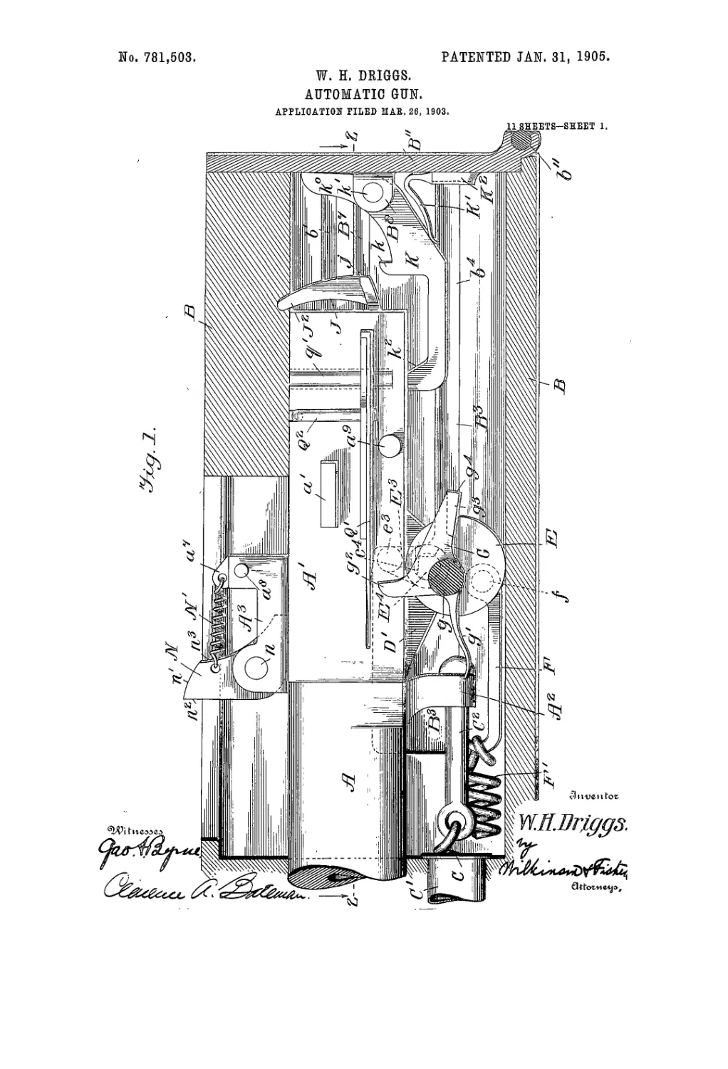
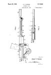
10 Figure 1 is a vertical section through the
casing along the line 1 1 of Fig. 2 and look-
ing in the direction of the arrows. Fig. 2
shows a horizontal section through the cas-
ing along the broken line 2 2 of Fig. 1, the
25 gun and breech-block and other mechanism
contained in the casing being shown in plan.
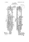
Fig. 3 shows a section along the broken line
3 3 of Fig. 2 and looking in the direction of the
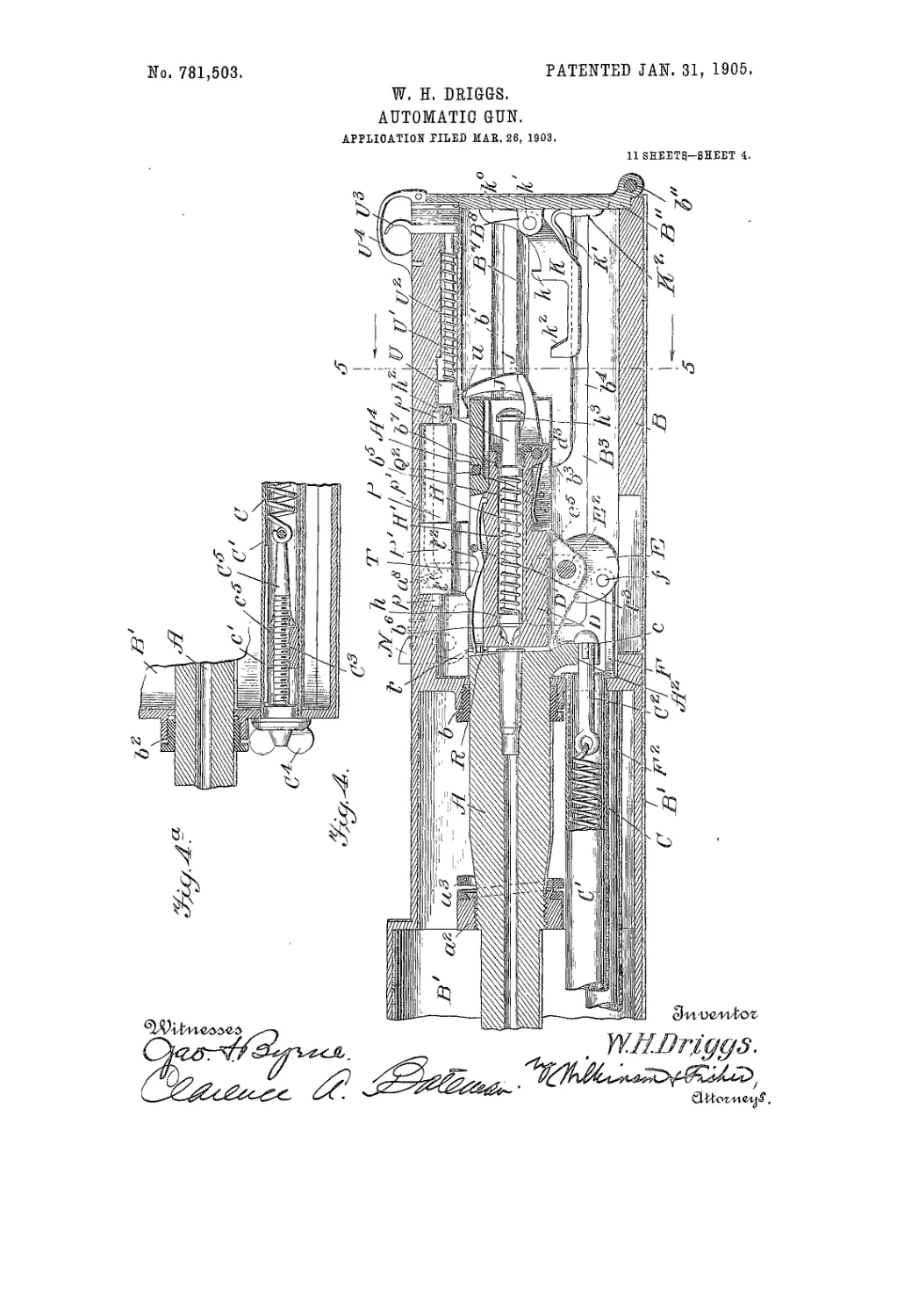
arrows. Fig. 4 is a central vertical section
30 through the gun and casing on a smaller scale,
parts being shown in elevation. Fig. 4a is a
fragmentary view showing the end of the
water-jacket near the muzzle of the gun with
the parts contained therein, the same being a
35 continuation of the left end of Fig. 4. Fig.
5 shows a cross-section along the line 5 5 of
Fig. 4 and looking in the direction of the ar-
rows, the scale being larger than in Fig. 4.
Fig. 6 is a detail sectional view showing the
4° construction of the hopper. Fig. 7 is a trans-
verse section showing the mode of feeding
the cartridges to the gun. This section is
taken on the line 7 7 of Fig. 2 and looking in
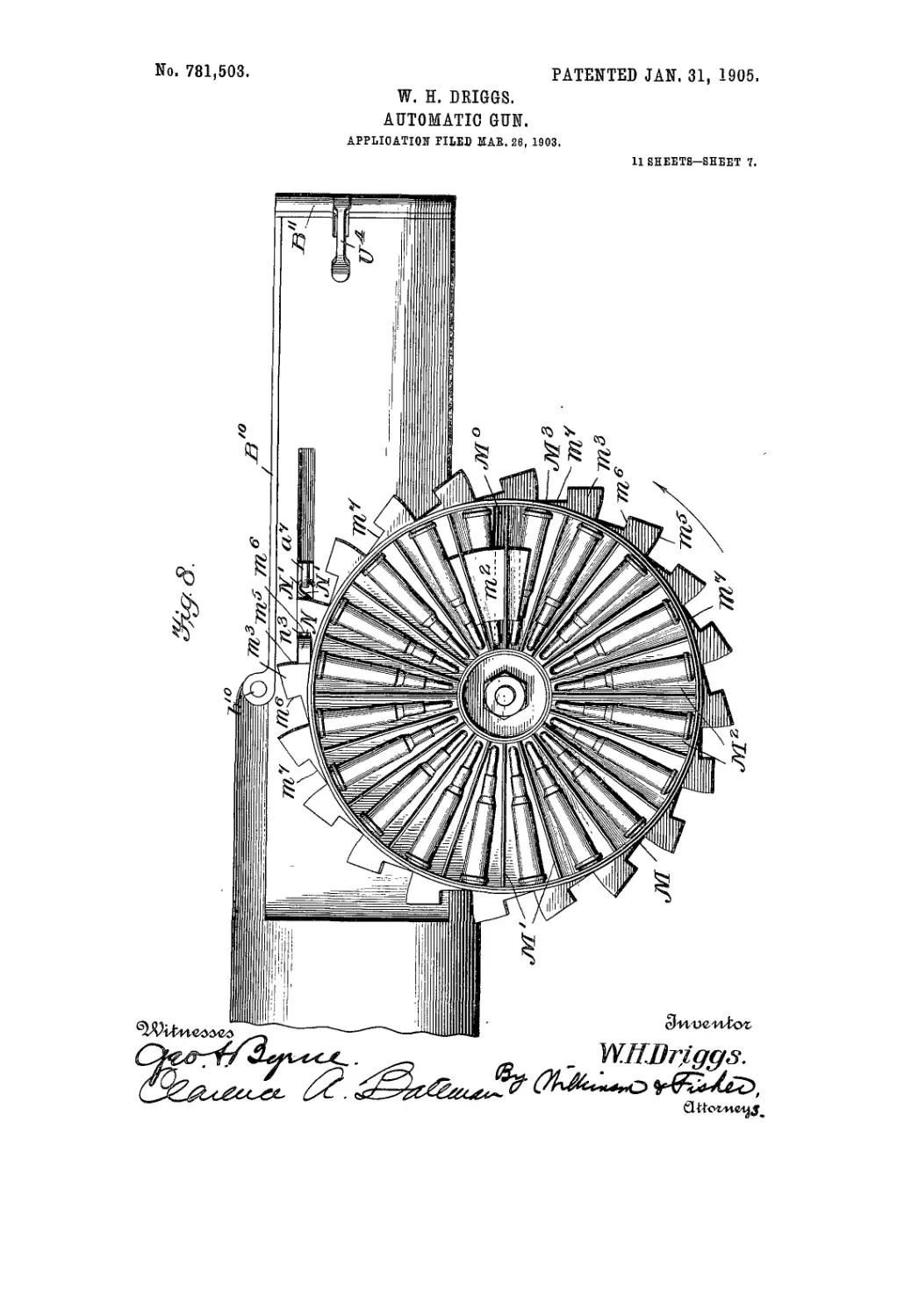
the direction of the arrows. Fig. 8 is a plan
45 view of the hopper and of the breech of the
gun. Fig. 9 is a detail showing in perspec-
tive one of the pivoted plates used to obstruct
the feed of the cartridges until the parts are
in the proper position. Figs. 10 and 11 are
details showing in perspective the rocking 50
toe for feeding the cartridges singly to the
gun. Fig. 12 is a detail showing in perspec-
tive the catch for holding the breech-block
in the open position and for releasing same
at the proper time. Fig. 13 is a side eleva- 55
tion of the breech-block, showing the firing-
pin cocked and the sear in engagement there-
with. Fig. 14 is a central vertical section
through the breech-block, showing the firing-
pin and sear in the position assumed after the 60
gun has been fired. Fig. 15 is a detail show-
ing the sear in perspective. Fig. 16 is a de-
tail of the ejector. Fig. 17 is a detail show-
ing the cocking-plate. Fig. 18 is a detail
showing the engagement of the catch and ec- 65
centric and illustrates the manner in which
the breech is held open after the gun recoils
and during the operation of loading. Fig.
19 represents a side elevation of the gun,
parts being broken away and parts being 70
omitted. Fig. 20 is a detail showing the
mechanism for running the gun in and out by
hand so as to start the firing, and Fig. 21 is a
section along the line 21 21 of Fig. 20 and
looking in the direction of the arrows. 75
A represents the body of the gun, which is
provided with a chambered breech A', a down-
wardly-projecting lug A8, and an upward ex-
tension A3. The chamber of the breech is
walled over near its rear end, as at A4. The 80
gun is mounted in the casing B, the forward
portion of which, B', is used as a water-jacket.
The breech and muzzle of the gun are cylin-
drical and fit close in the stuffing-boxes Ъ and
Z>2, (see Fig. 4 and Fig. 4a,) so that the gun 85
may recoil through the water-jacket. The
recoil of the gun is positively limited by means
of the bands a8 and a spring-buffer «3, attached
thereto, which brings up, against the casing
when the gun has recoiled- to the predeter- 90
mined limit. The gun is restored to the ini-
tial position by means of the spring C, which
is connected to the bolt C8, fast to the lug A8
on -the breech of the gun. This pin is con-
nected to said lug by a bayonet-joint arrange- 95
ment e. (Shown in Fig. 4.) The springC is
s
781,503
inclosed in a hollow tube C', which passes
through the water-jacket, and the forward end
of the spring is connected to a yoke C“. hav-
ing a nut <? splined, as at /, in the tube C',
5 in which nut the screw' C3 engages. This
screw’ is turned by means of the butterfly-
head C4, and thus the tension of the spring
may be adjusted as desired. Thus it will be
seen that the gun recoils through glands in
to the. water-jacket and is brought back to the
initial position by means of the spring C.
The breech-block D is mounted in the cham-
ber in the breech of the gun and is provided
with ribs /, which engage in the grooves a"
15 between the ribs «5 on the inner walls of the
gun-breech when the breech-block is in the
closed position. To open the breech, the
breech-block is moved downward and is auto-
matically held in the rear position after full
20 recoil, while to close the breech the block is
brought forward by a spring and is cammed
up into the locked position, as will now be de-
scribed. The breech-block is provided with
two downwardly-projecting lugs D', in which
25 lugs is journaled the shaft E2, carrying the
two eccentrics E and E', which rest on the.
floor of the casing. (See Fig. 7.) The ec-
centric E carries a w’rist-pin /, to which the
hook F is connected, the said hook engaging the
30 end of a coil-spring F', which spring projects
forward into the tube.F2, passing through the
water-jacket. . The tension of this spring is
adjusted in a similar way to the tension on the
spring C, which has already been fully de-
35 scribed. The tension on this spring F' tends1
to bring the eccentric E to the initial posi-
tion, with the breech closed, as shown in Fig.
• 1, and the breech-block is opened and held
opened against the action of the spring with
40 a mechanism that will now be described.
G, shown in detail in Fig. 12, represents a
pivoted locking-plate which has a pivot-arm
</ extending into a boss B5 in the casing, as
shown in Fig. 2. This plate has a spring-arm
45 </', that normally engages in a notch in the
casing B. It is also provided with an arm G4,
having a holding-face g4, adapted to engage
the face e of the stud E4 on the eccentric E,
as shown in Fig. 18, the eccentric then being
50 in the position indicated in Fig. 3 and the
breech being open. When the gun counter-
recoils, the stud o' strikes the rounded face of
the arm </2of the plate G. rocks the said plate
slightly about its pivot g, and the stud rides
55 under the said arm without affecting the op-
eration of any of the parts. As the gun re-
coils the wrist-pin <? on the arm E3, which
projects from and is integral with the eecbn--
tric’E, strikes the shoulder Ъ3 on the casing,
60 and further movement rearward of the gun
rocks the eccentric down to the position indi-
cated in Fig. 3, causing the shaft E2 to pull
the breech-block' downward out of engage-
ment with the grooves of the breech-block
65 chamber of the gun. At the same ti^e the
head 7/;l of the firing-pin is engaged by the
catch к of the plate K, which plate, is nor-
mally pressed upward about its pivot Z1' by
means of the spring K'. The said plate К
has an arm k" abutting against the casing, as 7°
shown in Fig. 3, and also an inclined face Z‘2
near the forward end adapted to be struck by
the lug <Г' on the breech-block D for releas-
ing the tiring-pin, as will be hereinafter more
fully described. When the gun carrying the 75
breech-block has reached the rearward posi-
tion, the spring (/’ throws the locking-arm gi
of the plate G in front of the shoulder on
the pin E4 fast to the eccentric E, and thus
the breech-block is held against motion for- 80
ward, while at the same time the gun itself
is free to return to the initial position under
the action of the spring C. As the gun nears
the closed position, having in the meantime
been loaded, as will'be hereinafter described, 85
the pin a’, carried by the breech of the gun,
strikes the arm g2 of the plate G, rocks the
same against the action of the spring </', and
causes the face g4 to release the shoulder e4,
(see Figs. 7 and 18,) thus allowing the spring 9°
F' to rock the eccentric E and with it the
shaft E2; but this eccentric cannot be rocked
by the spring F' until the ribs d register with
the grooves a° in the gun-breech. The nose
of the breech-block is so shaped, as shown in 95
Figs. 2, 3, and 13, that the face d* muststrike
the face a4 on the gun before the block can be
cammed up to the locked position. As soon
as the block has been dragged far enough for-
ward by the spring F' to cause the ribs d to 100
register with the grooves «° the tension of the
said spring will rock the eccentric and will
cam the block up into the locked position, as
shown in Fig. 4. As the breech-block moves
forward the shoulder к on the plate К holds 105
the head H3of the firing-pin, thus cocking
the latter, and when the lug d3 on the breech-
block strikes the inclined face Z" of the plate
the catch к is released from the head Л3 of the
firing-pin; but just before this is done the no
sear J passes in front of the flange on the
head of the firing-pin, and thus holds the
same, as shown in Fig. 13, the arm J' of the
sear being normally pressed upward by the
action of the spring J2, causing the face / on 115
said arm to engage the flange Л3, as before
stated. The sear is pivoted to the breech-
block, as at J2, and is on the opposite side of
the firing-pin from the plate K, already re-
ferred to. T2°
The firing mechanism is shown in detail in
Fig. 4 and Fig. 14, the pin being of the re-
bounding type, so as to clear the head of the
breech-block after the gun is fired, and thus
prevent premature discharge or injury to the I25
pin. This is accomplished by having the rings
h and Л' loose on the body of the pin H and
between which rings is a firing-spring H' un-
der compression. The forward ring h is
pressed by the spring against a shoulder If of гз°
?й1,вдЗ
3
в
5
ю
r5
20
25
3°
35
4°
45
5°
55
60
б5
the breech-block, and the rear ring H also en-
gages part of the breech-block. After the fir-
ing-pin has been cocked and released the in-
ertia of the pin will carry it forward far enough
to strike the primer of the cartridge before the
tension of the spring causes the head of the
firing-pin to be withdrawn into its chamber in
the breech-block, as shown in Fig. 14. For
convenience©? assemblingthe rear end of the
firing-pin is made in the form of a sleeve A3,
Screwed onto the main body, and this sleeve
passes through a bushing A6, screwed in the
breech-block. When the breech-block reaches
the closed position, the gun may be fired either
single fire by hand or automatically. To fire
single fire by hand, pull back on the trigger
U3 when the breech is closed. This will cause
the block U to press the sear downward and
release the firing-pin, or by keeping the trig-
ger in the rear position the gun will fire auto-
matically when the breech is closed. To pre-
ventaccidents, the block U is normally pressed
forward to the inoperative position by means
of the spring Us on the bar U', which connects
the trigger U3 with the said block. The trig-
ger-guard B7 serves also as a catch to hold the
hinged door B11 in the closed position, and thus
keep the end of .the casing closed.
To get rid of the empty cartridge-case, ex-
tractors R are provided on the front of the
breech-block, which extractors are preferably
made in two segments with a slot between, into
which slot the free end t of the ejector T is au-
tomatically thrown on account of recoil. This
ejector (shown in detail in Fig. 16) is in the form
of a curved spring having an operating-lug
t', a shoulder ?, adapted to engage the pin f
on the breech-block, and a swinging arm £4
with a catch Л adapted to engage in the recess
in the breech-block, as shown in Fig. 14. The
arm t! is pressed under the pin t3 and. the catch
t! is swung into its recess, and thus the ejector
is firmly held in place, but at the same time
may be readily removed or assembled should
occasion require.
The operation of the ejector is as follows:
When the gun is fired, it carries the breech-
block with it on recoil until the breech-block
is cammed downward. Now on counter-re-
coil the breech-block remains fast; but the
gun moving forward causes the lug a™ on the
transom A4 over the breech-block to strike
the lug "C on the ejector. This will give a
quick blow to the ejector, causing the arm t
to knock the cartridge out of the extractor,
whence it will drop through the opening in
the bottom of the frame. Ordinarily the
cartridge is dropped out; but in case it should
get jammed in the extractor the cartridge-
case will be positively ejected by the ejector,
as hereinbefore described. It will be obvious
that the extractors will grip the rim of the
cartridge-case as the breech-block is cammed
in the first operation of opening the breech
and that when the breech-block is held fast
and the gun moves forward the empty car-
tridge-case will be dragged put of the pow-
der-chamber.
I have thus described the opening and clos-
ing of the breech, the firing of the gun, and 70
the ejection of the empty cartridge-case. The
loading apparatus will now be described.
The cartridges are stored in a revolving
hopper which is divided by radial partitions
into a plurality of chambers and in each cham- 75
ber are piled one above another, with the small
end pointing in toward the center of the hop-
per. M indicates the hopper, and M' the ra-
dial partitions, which radial partitions are
cut away, asat m. (See Figs. 6 and 7.) The 80
hopper M is mounted above a base-plate M3,
which is provided with a socket M°, which
-socket fits over the cylindrical lug V on the
part B6 of the casing B. The hopper is revo-
luhly connected to the base by means of the 85
bolt N5. ' (See Fig. 6.) To the outer edge of
the hopper is secured a rack M3, having teeth
m3, which teeth have faces m! and with a
flat face between the two, as shown in
Fig. 8. The base-plate -M3 of the hopper has 90
a curved tongue да3 with a throat Me to re-
ceive the cartridges, which throat opens into
the throat B° in the frame B. Between each
fire the hopper is rotated one tooth, causing
the tongue гл3 to pass over another cartridge, 95
allowing the cartridge to fall in through the
throat M“, as indicated in dotted lines in Fig.
7.' This step-by-step motion is given to the
hopper by means of the arm N, which is piv-
oted, as at n, to the projection A3 on the gun, 100
and it carries a rounded face n', an engaging
face n\ and a locking face n3. This arm is
normally drawn upward to the position shown
in Fig. 3 by means of the spring N'i attached
to the lug сП on the projection A3. This pro- 105
jection also carries a pin a3. When the gun
is fired, this arm N recoils to the position in-
dicated in dotted lines in Fig. 3, the curved
face n'. on the arm N then passing under one
of the teeth on the hopper, the spring N' be- no
ing of light tension and readily yielding.
When the gun returns on account of recoil, the
face n3 strikes the face m3 of one of the teeth
m3 of the hopper (see Fig. 8) and rotates the
hopper through the angle subtended by one 115
tooth. At the same time the arm N will pro-
ject into the space between two teeth and
abutting against the flat face in! will prevent
the hopper from turning any farther than a
single tooth. To steady the hopper in place 120
while the arm N' is out of operative relation '
with the teeth on the edge of the .hopper, I
provide a spring-stop m\ which is held in a
bracket attached to the base-plate in! and
engages in notches m3 in the base of the hop- 125
per, which notches have inclined edges, so
that the stop ?w/4 automatically rides out of
these notches. It will be seen that as the hopr
per revolves the lower cartridges of each
column will roll along the base-plate M3 and . 130
4= 781,503
the tongue -m? will lift the column of car-
tridges from off of the lower cartridge, allow-
ing this to fall into the throat M“ and thence
to pass to the breech of the gun. Thus one
5 cartridge from the bottom of each radial
chamber will be fed to the gun during each
revolution of the hopper, so that the feed will
be continuous as long as there are cartridges
in the hopper. To prevent the cartridges
ro from crowding down into the breech of the
tbe gun, I provide the block P, which is
journaled on pins p and has an arm P' nor-
mally adapted to project down and block the
throat B° of the frame, as shown in Fig. 7.
15 This block is curved, as at P°, between the
arms P' and P2 to receive a single cartridge
when the block is rocked upward and then
to deposit the single cartridge in the breech
of the gun when the block is rocked down
20 again. The block is rocked by means of a
pin es on the gun which engages in the cam-
groove p' of the block P. As the gun recoils,
this pin rocks the block up and allows it to
receive one cartridge in the groove P° and on
25 counter-recoil the pin locks the block down
again, depositing the cartridge on top of the
guard-plates Q. These plates open and close
like the blades of a pair of scissors and are
operated by the breech-block, as will now be
30 described. There are two of these blades Q
and Q', both substantially alike, but having
the parts reversed and one mounted above
the other. One of the blades is shown in de-
tail in Fig. 9. Each of these blades has a long
35 journal 7', which is mounted in the groove in
the side of the breech of the gun, as shown in
Fig. 2, and the two blades are normally pressed
together by means of a loop-spring Q2, which
passes over tbe top of the breech of the gun
40 and engages in holes g* in the blades. Each
of the blades is provided with ribs or flanges
(Д 93 and <75, which not only serve to stiffen
the blades, but the former prevents the blades
from closing in too far, while the flanges 73
45 are for the face of breech-block to work on in
loading, and the flange 75 limits the opening
of the plate. The plate swings in and out of
the slot in the side of the gun-breech, as shown
in Fig. 7. It will be seen that if a cartridge
50 is fed above these plates it will remain rest-
ing thereon until the plates are open,’ and
this is accomplished by the action of the
. breech-block, as will be hereinafter described.
When.the breech-block is in tbe closed posi-
55 tion, it projects between these blades and holds
them open. Now if the gun be fired these
blades will move back with the gun on recoil
and will pass into the grooves B7 in the-cas-
ing (seef Figs. 2 and 7) and the outer wall of
60 these grooves will hold the blades in the open
position against the action of the spring Q2
until when on counter-recoil the rear end of
the blades passes the shoulder B9. Then the
blades will snap to the closed position under
65 the influence of the spring Q2. In the mean-
time the empty cartridge - case has dropped
through the opening between the blades. On
counter-recoil the pin on the gun causes
the block P to feed another cartridge above
1 the blades, and it remains resting on these. 7°
I blades until the breech-block starts forward
’ again. As soon as the edges tP at the side of
the nose of the breech-block strike the cam-
faces on the plates Q and Q' these plates
are spread apart and the breech-block shoves 75
the cartridge home.
In order that the parts may be put in posi-
tion for automatic firing, it will be necessary
to move the gun-barrel to the rear one or
more times before firing begins. This is ac- 80
complished by the mechanism shown in Figs.
19 to 21, in which the water-jacket B', in-
closing the gun, is mounted on the trunnions
V, supported on the mount W beneath the
cap-square W'. Any desired form of mount 85
may be used, so that details of the mount are
omitted. Fig. ‘19 shows the left side of the
gun; but on the opposite side of the gun and-
passing through the hollow trunnion is a
shaft X2, carrying the crank X', provided 9°
with a handle X. The end of this shaft is
made angular, as at sc, to fit in a socket in tbe
hub of the gear X3, which gear may be’at-
tached to the shaft X2 by means of a cotter-
pin X4 or in any other convenient way. This 95
gear X3 is in segmental form, as shown in Fig.
21, and is so constructed that when the han-
dle X is down, as indicated in Fig. 19, it will
be out of engagement with the rack Y', se-
cured to or integral with the sleeve Y on the юс
gun-barrel. Thus the gun-barrel may nor-
mally recoil without any engagement with
the gear X3. In beginning the operation of
firing, however, it will be necessary to move
the gun-barrel one or more times to the rear, ю;
in which case the handle X is swung upward
in the direction of the arrow in Figs. 19 and
21, causing the teeth on said gear to engage
in the teeth of the-rack Y' and moving the
gun to the rear to the desired distance. As
soon as the gun-barrel has been moved far
enough to the rear the teeth of the gear will be-
come disengaged from those of the rack, allow-
ing the spring C to restore the barrel to the ini-
tial position. The cycle of operations then is n;
as follows: Supposing there are no cartridges
in thegun and it is desired to commence firing,
one or more cartridges are conveyed into the
throat B9of the casing, as indicated in Fig. 7.
The cartridges may subsequently be fed in юс
by hand or the hopper N may be put in place.
There being one or more cartridges in the
throat B°, the gun-barrel is moved to the
rear by means of the handle X, as has just
been described, until the gear X3 passes over 12;
the rack Y', allowing the spring C to restore
the gun-barrel to the initial position. While
this is being done a cartridge is fed above the
plates Q and Q' and is shoved home by the
breech-block in the operation of closing the 13е
781,603
3'
breech, and when the breech is closed the gun
is either fired automatically or by hand, as be-
fore described. The motion of the gun on re-
coil and counter-recoil automatically opens
5 the hreech, causing the breech-bloek to with-
draw and eject the empty cartridge-case, cocks
the firing-pin, feeds a fresh cartridge, closes
the breech-block, and fires the gun. This cy-
cle of operations is automatically repeated in-
to definitely as long as the supply of cartridges
is maintained.
It will be seen that the various parts are so
constructed that they may be readily assem-
bled and dismounted without the use of any
15 special tools. Thus the side B10of the casing
swings outward about a hinge as shoWn in
Fig. 2. Also the end plate B11 of the casing
swings about the hinge j11 and is held in place
by tenon 7>12 and locked by the trigger-guard
20 U4. Thus the interior of the casing contain-
ing the hreech mechanism is readily accessi-
ble. Again, the catch К is connected to the
plateB by a bayonet-joint. Again, the spring
K' steps in a housing K8 and may be readily
25 inserted or removed when desired. Again,
the sear J may be placed in the breech-block
or removed therefrom at a single operation.’
Also the ejector T is held in place by the re-
siliency of the material of which it is made
30 and may be readily removed. Also the plates
Q and Q' may be taken out of their bearings
by simply removing the loop-spring Qs. Also
the bolt C:! is attached to the gun by a bayo-
net-joint. The block H may also be removed
35 from its journal-bearings, and, in fact, all of
the various parts of the gun may be readily
assembled and rapidly dismounted without
the use of any special tools and without re-
quiring any high degree of mechanical skill.
40 Moreover, it willbe seen that the various parts
are comparatively heavy and strong and are
not apt to get out of order; but if they do get
out of order repairs or alterations can be
readily made.
45 It will be obvious that various modifications
can be made in the herein-described mechan-
ism which could be used without departing
from the spirit of my invention.
Having thus described my invention, what
50 ] claim, and desire tosecure by LettersPatent
of the United States, is—
1. In an automatic gun, the combination
with the gun-body with a breech-block cham-
ber having intersecting grooves in the. walls,
55 thereof, of a breech-block having ribs adapt-
ed to slide upward and downward and longi-
tudinally in said,grooves, automatic means for
moving said breech-block downward out of en-
gagement with said grooves near the end of
60 the recoil of the gun, means for restoring the
gim to'the initial position on counter-recoil,
means for holding the breech-block back tem-
porarily during the counter-recoil of the gun,
and means for restoring the breech-block to
65 the initial position, substantially as described.
2. In an automatic gun, the combination
with the gun-body and a breech-block cham-
ber provided with grooves, of the breech-
block having ribs adapted to slide upward and
downward in said grooves and also to slide 7°
longitudinally relative to said gun-body, of
automatic means for releasing said breech-
block from engagement with said grooves
near the end of the recoil of the.,gun, auto-
maticmeans for holding the breech-block in 75
the rear position, means for returping the
gun-body to the initial position, and means
actuated by the counter-recoil of the gun for
releasing the breech-block, and means for re-
storing it to the initial position, substantially 80
as described.
3. In an automatic gun, the combination
with the gun-body free to recoil and a recoil-
spring for restoring the same to the initial
position, of a breech-block chamber secured 85
to or integral with said gun-body and provided
with grooves therein, a breech-block having
ribs engaging in said grooves and adapted to
slide up or down and longitudinally relative •
to said breech-block chamber, automatic 9°
means for releasing the ribs on said breech-
block from engagement with said grooves
when the gun nears the end of the recoil, au-
tomatic means for holding the ЬгеёсЬ-Ыо.ск
in approximately the rear position while the 95
gun-body returns to the initial position, means
actuated by the counter-recoil of the gun for
releasing said breech-block, and means for
automatically moving said breech-block, when
released, forward, and then upward to the юо
closed position, substantially as,described.
4. In an automatic gun, the combination
with the gun-body provided with a breech-
block chamber having slightly-inclined trans-
verse grooves and longitudinal grooves in the i°5
walls thereof, of a breech-block having inclined
ribs adapted to slide upward and downward in
said inclined transverse groovesand backward
and forward in said longitudinal grooves, au-
tomatic means for moving said breech-block no
downward out of engagement with said
grooves near the end of the recoil of the gun,
a spring for restoring the gun to the initial
position on counter-recoil, means for holding
the breech-block back temporarily during the 115
counter-recoil of the gun, and means for re-
storing the breech-block to the initial position,
substantially as described.
5. In an automatic gun, the combination
with the gun-body provided with a breech- 120
block chamber having slightly-inclined trans-
verse grooves and longitudinal grooves in the
walls thereof, of a breech-block having in-
clined ribs adapted to slide upward and,
downwardin said inclined transverse grPoves 125
and backward and forward in said longitudi-
nal grooves, automatic means for moving said
breech-block downward out of engagement
with said grooves near the end of the recoil
of the gun, a spring for restoring the gun to 13°
781,503
the initial position on counter-recoil, means
for holding the breech-block back temporarily
during the counter-recoil of the gun, and a
spring and cam automatically actuated by the
5 later movement of the gun on counter-recoil
for restoring the breech-block to the initial
- position, substantially as described.
6. In an automatic gun, the combination
with a casing with guide-grooves therein, of
о the gun-body having a breech-block chamber
provided with grooves, and guide-ribs on said
gun-body engagingsaid casing, a breech-block
having ribs adapted to slide upward anddown-
ward in the grooves in said breech-block cham-
5 ber and also to slide longitudinally relative to
said gun-body, of automatic means for releas-
ing said breech-block from engagement with
said grooves near the end of the recoil of the
gun, automatic means for holding the breech-
o block in the rear position, means for return-
ing the gun-body to the initial position, and
means actuated by the counter-recoil of the
gun for releasing the breech-block,-and means
for restoring it to the initial position, substan-
5 tially as described.
7. In an automatic gun, the combination
with a casing with guide-grooves therein, of
the gun-body having a breech-block chamber
provided with grooves, and guide-ribs on said
э gun-body engagingsaid casing, a-breech-block
having ribs adapted to slide upward and down-
ward in the grooves in said breech-block cham-
ber and also to slide longitudinally relative to
said gun-body, of automatic means for releas-
5 ing said breech-block from engagement with
said grooves near the end of the recoil of the
gun,"automatic means for holding the breech-
block in the rear position, means for return-
ing the gun-body to the initial position, and a
о spring with cam mechanism operated thereby,
actuated by the counter-recoil of the gun for
releasing the breech-block and restoring it to
the initial position, substantially as described.
8. In an automatic gun, the combination
5 with the gun-body free to recoil and a recoil-
spring for restoring the same to the initial po-
sition, of a breech-block chamber secured to
or integral with said gun-body and provided
with grooves therein, a breech-block having,
о ribs engaging in said grooves and adapted to
slide up or down and longitudinally relative
to said breech-block chamber,, means for re-
leasing the ribs on said breech-block from
engagement with said grooves when the gun
5 nears the end of the recoil, automatic means
for holding the breech-block in approximately
the rear position while the gun-body returns
to the initial position, means actuated by the
counter-recoil of the gun for releasing said
о breech-block, and a spring and cam mechan-
ism for automatically moving said breech-
block, when released, forward and then up-
ward to the closed position,'"substantially as
described. " ,
5 9. In an automatic gun, the combination
with the gun-body free to recoil and a recoil-
spring for restoring the same to the initial po-
sition, of a breech-block chamber secured to'
or integral with said gun-body and provided
with grooves therein, a breech-block having 7°
ribs engaging in said grooves and adapted to
slide up or down and longitudinally relative
to said breech-block chamber, means for re-
leasing the ribs on said breech-block from >
engagement with said grooves when the gun 75
nears the end of the recoil, a spring-controlled
toe for holding the breech-block in approxi-
mately the rear position while the gun-body
returns to the initial position, but tripped by
the gun on counter-recoi 1, and automatic mech- 80
anism for moving said breech-block, when re-
leased, forward and then upward to the closed
position, substantially as described.
10. In an automatic gun, the combination
with the gun - body with a breech - block 85
chamber having intersecting grooves in the
walls thereof, of a'breech-block having ribs
adapted to slide upward and downward and
longitudinally in said grooves, automatic
means for moving said breech-block down- 90
ward out of engagement with said grooves
near the end of the recoil of the gun. means-
for restoring the gun to the initial position
on counter-recoil, a pivoted catch for holding
the breech-block back temporarily, means ac- 95
tuated by the counter-recoil of the gun for
tripping said catch, and means for restoring
the breech-block to the initial position when
released, substantially as described.
11. In an automatic gun, the combination юс
with the gun-body and a breech-block cham-
ber provided with grooves, of the breech-
block having ribs adapted to slide upward
and downward in said grooves and also to
slide longitudinally relative to said gun-body, io;
a cam and mechanism operating same for re-
leasing said breech-block from engagement
with said grooves near the end of the recoil
of the gun and for restoring the same to the
closed position, a pivoted catch for holding rr>
the breech-block temporarily in the rear posi-
tion, means for returning the gun-body to the
initial position, and automatic means actuated
by the counter-recoil of the gun for tripping
said catch and releasing the breech-block, al- 115
lowing it to return to the initial position,
substantially as described. ’
12. In an automatic gun, the combination
vVith the gun-body and a recoil-spring for re-
storing the same to the initial position, of a 120
breech-block chamber secured to or integral
with said gun-body and provided with grooves
therein, a breech-block having ribs engag-
ing in said grooves and adapted to slide up
or doWn and longitudinally relative to said 125
breech-block chamber, of a cam and mechan-
ism operating same for releasing the ribs on
said breech-block from engagement with said
grooves when the gun nears the end of the re-
coil and for restoring the breech-block to the 13c
781,503
7
closed position, a spring-impressed catch for
bolding the breech-block in approximately
tbe rear position while the gun-body returns
to tbe initial position, means actuated by the
5 counter-recoil of the gun for tripping said
catch and releasing said breech-block, allow-
ing said breech-block to move forward and
then upward to the closed position when re-
leased, substantially as described.
io 13. In an automatic gun, the combination
with the gun-body provided with a breech-
' block chamber, of a breech-block adapted to
slide upward and downward in and to slide
rearward in said chamber, of automatic means
15 for moving said breech-block downward and
out of engagement with the walls of said
chamber near the end of the recoil of the gun,
automatic means for restoring the gun to the
initial position on counter-recoil, automatic
2o means for holding the breech-block back tem-
porarily during the counter-recoil of the gun,
and means for releasing said breech-block, and
means for restoring the same to the initial
position, when released, substantially as de-
25 scribed.
14. In an automatic gun, the combination
with the gun-body and a breech-block cham-
ber provided with dpwnwardly-inclined trans-
verse grooves, and also with rear ward ly-ex-
30 tending grooves, of a breech-block having
ribs adapted to slide upward, and downward
in said grooves and also to slide longitudinally
in said rearwardly:extending grooves, of au-
tomatic mehns for releasing said breech-block
35 from engagement with said grooves near the
end of the recoil of the gun, automatic means
for holding the breech-block,temporarily in
the rear position, means for returning the gun-
body to the initial position, and means actu-
40 ated by the counter-recoil of the gun for re-
leasing the breech-block, and means for re-
storing it to the initial position, substantially
as described.
15. In an automatic gun, the combination
45 with the gun-bodyfree to recoil and a recoil-
spring f dr restoring the same to the initial
position, of a breech-block chamber secured
to or integral with said gun-body and provided
with downwardly-inclined, and also with fear-
50 wardly-extending grooves therein, a breech-
block having ribs engaging in.said grooves
and adapted to slide up or down and longitu-
dinally relative to said breech-block chamber,
of a cam and mechanism operated by the re-
55 coil of the gun for releasing the ribs on said
breech - block from engagement with said
grooves when the gun nears the end of the
recoil, automatic means for holding the
breech-block in approximately the rear po-
60-sition while the gun-body returns to the ini-
tial position, means actuated, by the counter-,
recoil of the gun for- releasing said breech-
block, and a coil-springautbmatically moving
said breech-block forward when released, and
65 also operating said cam to move the breech-
block upward to the closed position when said
ribs and grooves register with each other, sub-
stantially as described.
16. In an automatic gun, the combination
with the gun-body provided with a breech- 7°
block chamber having slightly-inclined trans-
verse grooves and also longitudinal grooves in
the walls thereof, of a breech-block having in-
clined ribs adapted to slide upward and down-
ward in said inclined transverse grooves and 75
backward and forward in said longitudinal
grooves, automatic means for moving said
breech-block downward out of engagement
with said grooves near the end of the recoil of
tbe gun, an extractor mounted on the nose of 80
the breech-block and engaging the rim of the
cartridge-case when the breech-block moves
down, a spring for restoring the gun to the
initial position on counter-recoil, means for
holding the breech-block back temporarily 85
during the coupter-recoil of the gun, and
meahs for restoring the breech-block to the
initial position, when released, substantially
as described.,
17. In an automatic gun, the combination 9°
with the gun-body provided with a breech-
block chamber having slightly-inclined trans-
verse grooves and longitudinal grooves in the
walls thereof, of a breech-block having in-
clined ribs adapted to slide upward and down- Г 5
ward in said inclined transverse grooves and
backward and forward in said longitudinal
grooves, automatic means for moving said
breech-block downward out of engagement
with said grooves near the end of the recoil of юс
the gun, an extractor mounted on the nose of
. the breech-block and engaging the rim of the
cartridge-case when the breech moves down, a
resilient ejector mountpd on the breech-block
and operated by the gun on counter-recoil, ioj
aspring for restoring the gun to the initial
position on counter-recoil, means for holding
the breech-block back temporarily during the
counter-recoil of the gun, and means for re-
storing the breech-block to the initial position, 1 ic
when released, substantially as described.
18. In an automatic gun, the combination
vvith the gun-body provided with a .breech-
block chamber, having slightly-inclined trans-
verse grooves and also longitudinal grooves nf
in the walls thereof, of a breech-block hav-
ing inclined ribs adapted to slide upward
and downward in said inclined transverse '
grooves and backward and forward in said
longitudinal grooves, automatic means for 12c
moving said breech-block downward out of
engagement with said grooves near the end
of the recoil of the gun, an extractor mount-
ed on the nose of the breech-block and en-
gaging tbe rim of the cartridge - case when 12;
the breech moves down, a spring for restor-
ing the gun to the initial position on coun-
, ter - recoil, means for holding the breech-;
block back temporarily during the counter-
recoil of the gun, and a spring-and cam auto- 13c
781,503
&
matically actuated by the latter movement of
the gun on counter-recoil for restoring the
breech-block to the initial position, substan-
tially as described.
19. In an automatic gun, the combination
with the gun-body provided with a breech-
block chamber, having slightly-inclined trans-
verse grooves and also longitudinal grooves
in the walls thereof, of a breech-block hav-
ing inclined ribs adapted to slide upward
and downward is said inclined transverse
grooves, and backward and forward in said
longitudinal grooves, automatic means for
moving said breech-block downward out of
engagement with said grooves near the end
of the recoil of the gun, an extractor mount-
ed on the nose of the breech-block and en-
gaging the rim of the cartridge-case when
the breech moves down, a resilient ejector
mounted on the breech-block and operated by
the gun on counter-recoil, a spring for restor-
ing the gun to the initial position on coun-
ter-recoil, means for holding the breech-
block back temporarily during the counter^
recoil of the gun, and a spring and cam auto-
matically actuated by the later-movement of
the gun on counter-recoil for restoring the
breech-block to the initial position, substan-
tially as described.
20. In an automatic gun, the combination
with the gun-body with a breech-block-
chamber having slightly-inclined transverse
grooves, and also longitudinal grooves in the
walls thereof, of a breech-block having in-
clined ribs adapted to slide upward and down-
ward in said inclined transverse grooves and
backward and forward in said longitudinal
grooves, automatic means for moving said
oreech-block forward out of engagement with
said grooves near the end of the recoil of the
gun, a spring-impressed flring-pin mounted
n said breech-block and provided with ahead,
i spring-catch adapted to engage said head
md cock said pin during the first part of the
:‘orward movement of said breech-block, with
neans operated by the further movement of
die breech-block for releasing said catch, a
sear holding said pin in the cocked position
when released by said catch, means for trip-
ling said sear when the breech is closed, means
'or restoring the gun to the initial position on
lounter-recoil, and means for subsequently
•estoring the breech-block to the initial posi-
.ion, substantially as described.
21. In an automatic gun, the combination
vith the gun-body provided with a breech-
flock chamber, having slightly-inclined trans-
verse grooves and longitudinal groovesinthe
vails thereof a breech-block having inclined
ibs adapted to slide upward and downward
n said inclined transverse grooves and back-
yard and forward in said longitudinal grooves,
.utomatic means for moving said breech-block
townward out of engagement with said
grooves near the end of the recoil of the gun,
a spring for restoring the gun to the initial
position on counter-recoil, a spring-impressed
firing-pin mounted in said breech-block and
provided with a head, a spring-catch adapted
to engage said head and cock said pin during 70
the first part of the forward movement of said
breech-block, with means operated by the fur-
ther movement of the breech for releasing
said catch, a sear holding said pin in the cocked
position when released by said catch, means 75
for tripping said sear when the breech is
closed, means for holding the breech-block
back temporarily during the counter-rccoil of
the gun, and a spring and cam automatically
actuated by the later movement of the gun on 80
counter-recoil for restoring the breech to the
initial position, substantially as described.
22. In an automatic gun, the combination
with the gun-body provided with a breech-
block chamber having slightly-inclined trans- 85
verse grooves and also longitudinal grooves
in the walls thereof, of a breech-block having-
inclined ribs adapted to slide upward and
downward in said inclined transverse grooves,
and backward and forward in said longitudi- 90
nal grooves, automatic means for moving said
breech-block downward out of engagement
with said grooves near the end of the recoil
of the gun, a spring - impressed firing-pin
mounted in said breech-block, means for cock- 95
ing same during the early forward movement
of the breech-block, and for releasing same
when the breech-block returns to the closed
position, a spring for restoring the gun to the
initial position on counter-recoil, means for 100
holding the breech-block back temporarily
during the counter-recoil of the gun, and
means for restoring the breech-block to the
initial position when released, substantially as
described. 105
23. In an automatic gun, the combination
with the gun-body provided with a breech-
blockchamber, having slightly-inclined trans-
verse grooves and longitudinal grooves in the
walls thereof, of a breech-block having in- no
dined ribs adapted to slide upward and down-
ward in said inclined transverse grooves and
backward and forward in said longitudinal
grooves, automatic means for moving said
breech-block downward out of engagement 115
with said grooves near the end of the recoil
of the gun, a spring - impressed firing-pin
mounted in said breech-block, means for cock-
ing same during the early forward movement
of the breech-block, and for releasing same 12c
when thebreech-block returns to the closed po-
sition, a spring for restoring the gun to.the
initial position on counter^recoil, means for
holding the breech-block back temporarily
during the counter-recoil of the .gun, and a 125
spring and cam automatically actuated by the
latter movement/)!’ the gun on coiinter-recoil
for restoring the breech-block to the initial
position, substantially as described.
24. In-an automatic gun, the combination 13°
78 МОЗ
with the gun-body having a breech-block
chamber provided with grooves, of a breech-
block having ribs adapted to slide upward
and downward and rearward in said grooves,
5 of automatic means for releasing said breech-
block from engagement with said grooves
near the end of the recoil of the gun, a spring-
impressed firing-pin mounted in said breech-
block, means for cocking same during the
io early forward movement of the breech-block,
and for releasing same when the breech-block
returns to the closed position, automatic
means for holding the breech - block in the
rear position, means for returning the gun-
15 body to the initial position, and means actu-
ated by the counter-recoil of the gun -for re-
leasing the breech-block, and means for re-
storing it to the initial position, substantially
as described.
20 25. In an automatic gun, the combination
with the gun-body having a breech-block
chamber provided with grooves, of a breech-
block having ribs adapted to slide upward
and downward and rearward in said grooves,
25 of automatic means for releasing said breech-
block from engagement with said grooves
near the end of the recoil of the gun, a spring-
impressed firing-pin mounted in said breech-
block and provided with a head, a spring-
s’3 catch adapted to engage said head and cock
said pin during the first part of the forward
movement of said breech-block, with means
operated by the further movement of the
breech-block for releasing said catch, a sear
35 holding said pin in the cocked position when
released by said catch, means for tripping
said sear when the breech is closed, automatic
means for holding the breech-block in the
rear position, means for returning the gun-
40 body to the initial position, and means actu-
ated by the counter-recoil of the gun for re-
leasing the breech-block, and means for re-
storing it to the initial position, substantially
as described.
45 26. In an automatic gun, the-combination
with a casing with guide-grooves therein, of
the gun-body having a breech-block chamber
provided with grooves, and guide - ribs on
said gun-body engaging said casing, a breech-
50 block having ribs adapted to slide upward
and downward in the grooves in said breech-
block chamber and also to slide longitudinally
relative to said gun-body, of automatic means
for releasing said breech-block from engage-
55 ment with said grooves near the end of the
recoil of the gun, a spring-impressed firing-
pin mounted in said breech-block, means for
cocking same during the early forward move-
ment of the breech-block, and for releasing
60 same when the breech-block returns to the
closed position, automatic means for holding
the breech-block in the rear position, means
for returning the gun-body to the initial po-
sition, and a spring with cam mechanism
operated thereby, actuated by the counter- 65
recoil of the gun for releasing the breech-
block and restoring it to the initial position,
substantially as described.
27. In an automatic gun, the combination
with a casing with guide-grooves therein, of 70
the gun-body having a breech-block chamber
provided with grooves, and guide-ribs on said
gun-body engagingsaid casing, a breech-block
having ribs adapted to slide upward and down-
ward in the grooves in said breech-block 75
chamber and also to slide longitudinally rela-
tive to said gun-body, of automatic means for
releasing said breech-block from engagement
with said grooves near the end of the recoil of
the gun, a spring-impressed firing-pin mount- 80
ed in said breech-block and provided with a
head, a spring-catch adapted to engage said
head and cock said pin during the first part of
the forward movement of said breech-block,
with means operated by the further move- 85
ment of the breech-block for releasing said
catch, a sear holding said pin in the cocked po-
sition when released by said catch, means for
tripping said sear when the breech is closed,
automatic means for bolding the breech-block 9°
in the rear position, means for returning the
gun-body to the initial position, and a spring
with cam mechanism operated thereby, actu-
ated by the counter-recoil of the gun for re-
leasing the breech-block and restoring it to the 95
initial position, substantially as described.
28. In an automatic gun, the combination
with a casing with guide-grooves therein, of
the gun-body having a breech-block chamber
provided with grooves and guide-ribs on said юс
gun-body engaging said casing, spring-im-
pressed guard-plates pivoted on said gun-body
and projecting into grooves in said casing, and
also into said block-chamber, a breech-block
having ribs adapted to slide upward and down- i°5
ward in the grooves in said breech-block cham-
ber and also to slide longitudinally relative to
said gun-body, and to project between said
plates when in the closed position, of auto-
matic means for releasing said breech-block n®
from engagement with said grooves in the
breech-block chamber near the end df the re-
coil of the gun, automatic means for holding
the breech-block in the rear position, means
for returning the gun-body to the initial po- 115
sition, means for feeding cartridges seriatim
above said plates, and means actuated by the
counter-recoil of the gun for releasing the
breech-block, and means for restoring it to the
initial position, substantially as described. 120
29. In.an automatic gun, the combination
with a casing with guide-grooves therein, of
the gun-body having a breech-block chamber
provided with grooves and guide-ribs on said
gun-body engaging said casing, spring-ini- 125
pressed guard-plates pivoted on said gun-body
and projecting into grooves in said casing, and
also into said breech-block chamber, a breech-
IO
781,503
block having ribs adapted to slide upward and
downward in the grooves in said breech-block
chamber and also to slide longitudinally rela-
tive to said gun-body and to project between
said plates when in the closed position, of au-
tomatic means for releasing said breech-block
from engagement with said grooves in the
breech-block chamber near the end of the re-
coil of the gun, automatic means for holding
the breech-block in the rear position, means
for returning the gun-body to the initial po-
sition, means for feeding cartridges seriatim
above said plates, and a spring with cam mech-
anism operated thereby, actuated by the coun-
ter-recoil of the gun for releasing the breech-
block and restoring it to the initial position,
substantially as described.
30. In an automatic gun, the combination
with a casing provided with guide-grooves
therein, of a gun-body mounted to recoil in
said casing and having lugs projecting into
said guide-grooves, said gun-body being pro-
vided with breech-block chamber with slots
through the side walls thereof, a breech-block
adapted to be moved upward, downward, and
rearward relative to said chamber, guard-
plates pivoted to said gun-body and project-
ing into said slots in the walls of the breech-
block chamber and also in the grooves in the
casing, of a spring normally tending to snap
said plates together when the breech is open,
but allowing the breech-block to spread said
plates apart in closing the breech, with means
for feeding cartridges seriatim to the top of
said plates when the breech is open,, substan-
tially as described.
31. In an automatic gun, the combination
with a casing provided with guide-grooves
therein, of a gun-body mounted to recoil in
said casing and having lugs projecting into
said guide-grooves, said gun-body being pro-
vided with a breech-block chamber with slots
through the side walls thereof, a breech-block
adapted to be moved upward, downward, and
rearward relative to said chamber, guard-
plates pivoted to said gun-body and project-
ing into said slots in the walls of the breech-
block chamber and also in the grooves in the
casing, of a spring normally tending to snap.
said plates together when the breech is open,
but allowing the breech-block to spread said
plates apart in closing the breech, extractor
mechanism carried by the breech-block and
ejecting the empty cartridge-case before said
plates snap to, with means for feeding car-
tridges seriatim to the top of said plates when
the breech is open, substantially as described.
32. In a breech-loading gun, the combina-
tion with the gun-body provided with a rear-
ward extension and a breech-block chamber
therein, of a breech-block reciprocating in said
chamber with means for locking said breech-
block in said chamber, guard-plates pivoted
to lhe gun-body and projecting through slots
in the walls of said chamber and normally 65
forming a bottom therefor when the breech
is open, but spread apart by the breech-block'
when the latter is in the closed or partially-
closed position, and a spring normally tend-
ing to snap the said plates together against 70
the wedging action of said breech-block, with
means for feeding cartridges seriatim on said
plates when the breech is open, substantially
,as described.
33. In a breech-loading gun, the combina- 75
tion with the gun-body provided with a rear-
ward extension and a breech-block chamber
therein, of a breech-block reciprocating in said
chamber with means for locking said breech-.
block in said chamber, guard-plates pivoted 80
to the gun-body and projecting through slots
in the walls of said chamber and normally
forming a bottom therefor when' the breech
is open, but spread apart by the breech block
when the latter is in the closed or partially- 85
closed position, and a spring normally tending
to snap the said plates together against the
wedging action of said breech-block, extractor
mechanism carried by the breech-block and
ejecting the empty case while the plates are 90
spread apart by the breech-block, with means
for feeding cartridges seriatim above said
plates when the breech is open, substantially
as described.
34. In an automatic gun, the combination 95
with a casing and a water-jacket secured to or
integral therewith and stuffing-boxes in said
water-jacket, of a gun-barrel recoiling in said
stuffing-boxes, a tube extending through said
water-jacket, and a recoil-spring mounted in 100
said tube and connected to the gun-body, sub-
stantially as described.
35. In an automatic gun, the combination
with a casing and a water-jacket secured to or
integral therewith and stuffing-boxes in said 105
water-jacket, of a gun-barrel recoiling in said
stuffing-boxes, a tube extending through said
water-jacket, and a recoil-spring mounted in
said tube and connected to the gun-body, with
means for adjustingthe tension on said spring, no
substantially as described.
36. In an automatic gun, the combination
with a casing and a water-jacket secured to or
integral therewith and stuffing-boxes in said
water-jacket, of a gun-barrel recoiling in said 115
stuffing-boxes, a tube extending through said
water-jacket, and a recoil-spring mounted in
said tube and connected to the gun-body, with
a screw projecting into the front end of said
tube and secured to said spring, and means for 120
setting up on said screw and thereby adjusting
the tension on said spring, substantially as de-
scribed.
37. In an automatic gun, the combination
with a casing and a water-jacket secured to or 125
integral therewith and stuffing-boxes in said
water-jacket,of a gumbarrel recoilingthrough
said stuffing-boxes, a slotted lug projecting
781,503
11
5
ю
15
20
25
3°
35
4°
45
5°
55
60
from said gun-barrel, a tube extending through
said water-jacket, a recoil-spring mounted in
said tube, and a bolt and bayonet-joint con-
necting said spring with said lug, substantially
as and for the purposes described.
38. In an automatic gun, the combination
with a casing and a water-jacket secured to or
integral therewith and stuffing-boxes in said
water-jacket,of a gun-barrel recoilingthrough
said stuffing-boxes, a slotted lug projecting
from said gun-bar rel, a tube extending thro ugh
said water-jacket, a recoil-spring mounted in
said tube, and a bolt and bayonet-joint con-
necting said spring with said lug, with means
provided at the opposite ends of said tube for
adjusting the tension on said spring, substan-
tially as described.
39. In an automatic gun, the combination
with a casing and a water-jacket secured to or
integral therewith, with stuffing-boxes in said
water-jacket, of a gun-barrel sliding in said
stuffing-boxes, a breech-block and breech
mechanism, and two tubes projecting through
said water-jacket, a coil-spring in each tube,
the one connected to the gun to restore it to
the initial position and the other connected to
the breech mechanism for operating the same,
substantially as described.
40. In an automatic gun, the combination
with a casing and. a water-jacket secured to or
integral therewith, with stuffing-boxes in said
water-jacket, of a gun-barrel sliding, in said
stuffing-boxes, a breech-block and breech
mechanism, and two tubes projecting through
said water-jacket, a coil-spring in each tubej'
the one connected to the gun for restoring it
to the initial position, and the other connect-
ed to the breech mechanism for operating the
same, with means for adjusting the tension
of the springs in said tubes, substantially as
described.
,41. The combination with thegnn-body hav-
ing a breech-block chamber in its breech, with
a breech-block sliding longitudinally in said'
chamber and guard-plates pivoted to said gun-
body, and projecting into said chamber and
normally spread apart by said breech-block,
with means for swinging said guard-plates
together when the breech-block is withdrawn,
substantially as described.
42. The combination with thegun-body hav-
ing a breech-block chamber in its breech with
a breech-block sliding longitudinally in said
chamber and guard-plates pivoted to said gun-
body, and projecting into said chamber and
normally spread apart by said breech-block;
with a spring for swinging said guard-plates
together when the breech-block is withdrawn,
substantially as described.
43. The combination with thegun-body hav-
ing a breech-block chamber in its breech with
a breech-block sliding longitudinally in said
chamber and guard-plates pivoted to said gun-
body, and projecting into said chamber and
normally spread apart by said breech-block, 65
with a U - shaped spring passing over the
breech of the gun and having its ends engag-
ing said plates, substantially as and for the
purposes described.
44. The means for arresting the cartridge 7c
in a breech-loading gun which consists of a
pair of guard-plates pivoted to the gun-body
and projecting into the breech-block cham-
ber, and a spring tending to draw said guard-
plates together and obstruct the passage for 75
the cartridge through said chamber, substan-
tially as described.
45. In an automatic gun, the means for be-
ginning the cycle of operations by hand, which
comprises a rack attached to the gun-barrel, 80
and a shaft passing through one of the trun-
nions of the gun, a segmental pinion mount-
ed on said shaft normally out of engagement
with said rack, but engagingsame when turned
through the required angle, and a hand-crank 85
for turning said pinion, substantially as de-
scribed.
46. In an automatic gun, the combination
with the casing and the gun-barrel mounted
to recoil in said casing, of a hollow trunnion 90
forming one of the bearings of said casing, a
shaft projecting through said hollow trun-
nion, a segmental gear on one end of said
shaft and a hand-crank on the other, and a
rack attached to the gun-barrel and normally 95
disengaged from but engaging with said seg-
mental gear when said handle is turned, where-
by the gun is moved to the rear against the
action of the recoil-spring and is automatic-
ally released at the desired moment, substan- 1 о
tially as and for the purposes described.
47. In a loading apparatus for guns of the
character described, the combination with a
casing with a throat therein opening above the
breech-block chamber, of a block P pivoted 105
in said casing and having an arm P' normally
adapted to block said throat, and a curved
groove P° to receive a single cartridge, with
a cam-groove p' on the back of said block,
and a stud carried by the gun-body and en- no
gaging in said cam-groove to rock said block,
whereby the. cartridges are fed seriatim to
the breech-block chamber after each fireof the
gun, substantially as described.
48. In a loading apparatus for guns of the 115
character described, the combination with the
casing provided with a throat for the passage
of cartridges, of the gun-body sliding there-
in, a revoluble hopper mounted above said
casing and divided by a series of radial par- 120
titions into wedge-shaped chambers, each
adapted to contain a column'of cartridges, a
circular rack on the base of the hopper hav-
ing flat faces between the teeth, a spring-pawl
carried by the gun for rotating the hopper 125
through the angle subtended by the said cham-
ber after each tire of the gun, the said pawl
having a flat edge adapted to contact with one
12
781,503
of the flat faces between said teeth and thus
arrest the further rotation of the hopper,
means for withdrawing the cartridges seriti-
tiui from the bottom of each chaniber as the
5 hopper rotates, and feeding same to the gun,
substantially as described.
49. In an automatic gun, the combination
with a casing provided with guide-grooves and
a shoulder on the inner walls thereof, of agun-
। ° body mounted to slide in said casing, a breech-
block mounted to slide up and down and lon-
gitudinally in the breech-block chamber of
said gun-body and provided with downwardly
projecting lugs, a shaft journaled in said lugs,
15 eccentrics mounted on said shaft and normal ly
bearing on the floor of said casing and support-
ing the breech-block, a spring under tension
normally tending to hold said eccentrics with
their maximum throw upward, thus holding
2° the breech-block in the closed position, an arm
carried by said shaft and adapted to strike said
shoulder in said casing as the gun recoils,
whereby said shaft is rocked, causing said
eccentrics to draw said breech-block down-
25 ward, a spring-catch locking said eccentrics
against the action of said spring when the
breech-block is in the open position, and
means actuated by the counter-recoil of the
gun for tripping said spring-catch and releas-
30 ing said eccentrics, whereby the breech-block
is dragged forward by said spring and then
moved upward to the initial position, substan-
tially as described.
50. In an automatic gun, the combination
35 with a casing provided with guide-grooves and
a shoulder on the inner wall thereof, of a gun-
body mounted to slide in said casing, a breech-
block mounted to slide up and down and lon-
gitudinally in the breech-block chamber of
4° said gun-body and provided with downwardly-
projecting lugs, a shaft journaled in said lugs,
eccentrics mounted on said shaft and normally
bearing on the floor of said casing and sup-
porting the breech-block, a spring under ten-
45 sion normally tending to hold said eccentrics
with their maximum throw upward, thus hold-
ing the breech-block in the closed position, an
arm carried by said shaft and adapted to strike
said shoulder in said casing as the gun re-
s’3 coils, whereby said shaft is rocked, causing
said eccentrics to draw said breech-block down-
ward, a spring-catch locking said eccentrics
against the action of said spring when the
breech-block is in the open position, a toe on
55 said spring-catch, and a projection on the gun
adapted to engage said toe on counter-recoil
and trip said catch, whereby the said spring
is free to drag said breech-block forward and
to operate said eccentric, causing it to move
5° the breech-block to the closed position, sub-
stantially as described.
51. In an automatic gun, the combination
with a breech-block adapted to slide down-
ward and longitudinally relative to the gun,
65 of an extractor secured to the nose of said
breech-block and adapted to engage the rim
of the cartridge-case in its downward motion
and to draw the cartridge-case out on counter-
recoil, substantially as described.
52. In an automatic gun, the combination 70
with a breech-block adapted to move back-
ward with the gun and then to slide, down-
ward, of a bifurcated extractor mounted on
the nose of said breech-block, and a spring-
ejector mounted on the top of said breech- 75
block and adapted to be struck by the gun
on counter-recoil prior to the return of the
breech block to the initial position, substan-
tially as described.
53. In an automatic gun, the combination 80
with a casing and a gun-body mounted to.re-
coil therein, of a breech-block adapted to move
downward and longitudinally relative to said
gun. means for holding the breech-block tem-
porarily in the rear position, and an extractor 85
carried by the nose of said breech-blocband
adapted to engage the rim of the cartridge-
case and to pullout the cartridge-case during
the counter-recoil of the gun, substantially as
described. 9°
54. In an automatic gun, the combination
with a casing and a gun-body mounted to re-
coil therein, of a breech-block adapted to move
downward and longitudinally relative to said
gun, means for bolding the breech-block tem- 95
porarily in the rear position, a bifurcated ex-
tractor secured to the nose of the breech-block
and adapted to engage the rim of the cartridge-
case when the breech-block descends and pull
the cartridge-case out of the gun on counter- too
recoil, and a spring-ejector mounted on the
top of the breech-block and pressed into the
bifurcation of said extractor by the gun-body
on counter-recoil, substantially as described.
55. The combination with a breech-block Io5
adapted to move downward and longitudinally
relative to the gun, of an extractor operated
by the breech-block and a resilient ejector
formed of a single spring fitting in a groove
on the top of the breech-block with a tongue 110
engaging in a notch' in said breech-block and
a pin on the breech-block engaging said ejec-
tor and holding the same in place, substan- .
tially as described.
56. The combination with the breech-block n5
D grooved on its top, of an extractor carried
by the breech-block and a resilient ejector T
having the tongue t5 fitting in a notch in the
top of the breech-block, a shoulder 72, and a
lug t' adapted to be struck by the gun-body 120
on counter-recoil, and a pin 1? in the top of the
breech-block engaging the said shoulder
substantially as described.
57. The combination with a„ casing and a
gun mounted to recoil therein, of a breech- I25
block mounted in said gun and adapted to
move backward therewith and then to move
down ward, a lug on said breech-block, a spring-
impressed firing-pin provided with'a head
and mounted in said breech-block, a spring- T3°
781,503
impressed catch adapted to engage the head
of said firing-pin when the breech-block is
moved down, a toe on said catch engaging
said lug when the breech - block moves for-
5 ward, a spring-sear carried by the breech-
block and adapted to engage the head of said
firing-pin and hold the same in the cocked
position after it has been released from said
catch, and means for tripping said sear when
io the breech-block reaches the closed position,
substantially as described.
58. A casing for automatic guns consisting
of a substantially rectangular box having
grooves in the side walls thereof, one side of
15 said box being hinged to swing out freely,
the end of said box being closed by a hinged
plate, tenoned to register with a groove in the
end of the hinged side,- with a firing mechan-
ism controlled by a trigger mounted in said
casing,and a combined latch and trigger-guard 20
for bolding said end plate to said hinged side
and for protecting said trigger, substantially
as described.
In testimony whereof I affix my signature in
presence of two witnesses.
WILLIAM HALE DRIGGS.
Witnesses:
J. Stephen Giusta,
Fred W. Englert.