/
Tags: weapons military affairs patent
Year: 1907
Text
No. 861,939,
PATENTED JULY 30, 1907.
L. V. BENET & H. A. MEROIE.
GAS OPERATED GUN.
APPLICATION PILED FEB. 21, 1907.
28 SHEETS—SHEET 1.
Ro 861,939 PATENTED JULY 30, 1907.
L. V. BENET & H. A. MERCI&
GAS OPERATED GUN.
APPLICATION PILLED ГЕВ. 21, 1207.
" 28 SHEETS-SHEET 2.
No. 861,939.
PATENTED JTJL.Y 30, 1907.
L. V. BENET & H. A. MERCI1S.
GAS OPERATED GUN.
APPLIOATIOH TILED TEB. 21, 1007.
28 SHEETS—SHEET 8.
No, 861,939. PATENTED J*ULY 30, 1907.
L. V. BENET & H. A. MEROIE.
GAS OPERATED GUN.
APPLICATION PILED FEB, 21, 1907.
28 SHEETS—SHEET 4.
L.l/. Hewett; "
/j./JA/tevTO/E: f
No. 861,939.
PATENTED JULY 30, 1907.
L. V. BENET & H. A. MERCIE.
GAS OPERATED GUN.
APPLI0AT10H FILES FEB. 21, 1907.
‘ ’ a
28 SHEETS-SHEET 5.
V
ekwe-H/to-cs
z
ЯЯМеяые:,
j£Ltt<yr^e^5L
Ъ—
Ко. 861,939.
PATENTED JULY 30, 1907.
L. V. BENET & H. A. MERCI&
GAS OPERATED GUN.
APPLIOATIOH FILED FEE. 21, 1007.
28 SHEETS—SHEET 6.
No. 861,939.
PATENTED JULY 30, 1907.
L. V. BENET & H. A. MEROIE.
GAS OPERATED GUN.
APPLICATION FILES FEB. 31, 1007.
28 SHEETS—SHEET 7.
й '
cl-kuwwto^
М4-//^£7У4т:
No. 861,939. PATENTED JULY 30, 1907.
L. V. BENET & H. A. MERCIE.
GAS OPERATED GUN.
APPLIOATIOH PILED EEB. 21, 1007.
28 8HEETB-8HEET-8.
No- 861,939. PATENTED JULY 30, 1907.
• L. V. BENET & H. A. MEROltf.
GAS OPERATED GUN.
APPLICATION FILED FEB. 21, 1907.
28 SHEETS-SHEET 9.
No. 861,939. PATENTED JULY 30, 1907.
L. V. BENET & H. A. MEROIE.
GAS OPERATED GUN.
APPLICATION FILED FEB. 21,1807.
28 ВИЕЕТ8—8ИЕЕТ 10.
No. 861,939.
PATENTED JULY 30, 1907.
L. V. BENET & H. A. MERCIE.
GAS OPERATED GUN.
APPLICATION PILED FEB. 21, .007. gheets_sheet Ц.
dttuvvietjS
No. 861,939. , PATENTED JULY 30, 1907.
L. V. BENET & H. A. MERCIE.
GAS OPERATED GUN.
APPLICATION FILED FSB. 31, 1907.
28 SBEET8—SHEET 12.
No, 861,939. PATENTED JULY 30, 1907
L. V. BENET & H. A. MEROIE.
GAS OPERATED GUN.
APPLIOATIOH PILES ГЕВ. 31, 1907.
28 SHEETS-BESET 13.
No. 861,939.
PATENTED JULY 30, 1907.
I». V. BENET & JL A. MERCIE.
GAS OPERATED GUN.
APPLICATION FILES TBE. 21, 1S07,
88 SHEETS—8ИЕЕТ 14.
No. 861,939 PATENTED JULY 30, 1907.
L. V. BENET & H. A. MERCIE.
GAS OPERATED GUN.
No. 861,939. PATENTED JULY 30, 1907.
L. V. BENET & H. A. MEROIE.
GAS OPERATED GUN.
APPLICATION TILLED ГЕВ. 21, 1907.
• 28 SHEETS—SHEET 16.
Svtwniozs
£Lttotmet|S.
No. 861,939.
PATENTED JULY 30, 1907.
L. V. BENET & H. А. МЕВС1Й.
GAS OPERATED GUN.
APPLICATION TILED ГЕВ. 21, 1907.
28 SHEETS—SHEET Д7.
No. 861,939.
PATENTED JULY 30, 1907.
L. V. BENET & H. A. MERCIE.
GAS OPERATED GUN.
APPLIOATIOH TILES ГЕВ. 21, 1807.
28 SHEETS—SHEET 18.
No, 861,93^
PATENTED JULY 30, 1907.
L. V. BENET & H. A. MEROlff. <
GAS OPERATED GUN.
APPLIOATIOH TILED EEB, 31, 1907.
28 SHEETS—SHEET 19.
No, 861,939. , PATENTED JULY 30, 1907
L. V. BENET & H. A. MERCIE'.
GAS OPERATED GUN.
APFLIOATIOH FILED FEB. SI, 1907.
28 SHEETS—SHEET 20.
No. 861,939.
PATENTED JULY 30, 1907.
L. V. BENET & H. A. MERCIE.
GAS OPERATED GUN.
APPLICATION FILES FEB. 21, 1907.
28 SHEETS—SHEET 21.
N,o. 861,939.
PATENTED JULY 30, 1907.
L. V. BENE'! & H. A. MERCIE.
GAS OPERATED GUN.
APPLIOATIOK TILED ГЕВ.21, 1007.
28 SHEETS—SHEET 23.
No. 861,939.
PATENTED JULY 30, 1907.
,L. V. BENET & H. A. MERCIE.
GAS OPERATED GUN.
APPLICATION PILED PEB. 21, 1907.
28 SHEETS—SHEET 24.
No, 861,939. PATENTED JULY 30, 1907.
Ь. V. BENET & H. A. MERCIE.
GAS OPERATED GDN.
APPLICATION FILED FEB. 21, 1007.
28 SHEETS—SHEET 28.
No. 861,939.
PATENTED JULY 30, 1907.
L. V. BENET & H. A. MERCIE.
GAS OPERATED GJN.
APPLICATION PILED FEB. 21, 1907.
28 SHEETS—SHEET. 26
^о. 861,939. PATENTED JULY 30, 1907.
L. V. BENET & H. A. MERCIE.
GAS OPERATED GUN.
APFLIOATJON FILES FEB. 21. 1907.
28 SHEETS-SHEET 27.
No. 861,939. PATENTED JULY 30, 1907.
L. V. BENET & H. A. MERCIE.
GAS OPERATED GUN.
APPLICATION PILES TEB. 21, 1807.
28 SHEETS—SHEET 28.
UNITED STATES PATENT OFFICE.
’LAURENCE V. BENET AND HENRI A. MERCIE, OF PARIS, FRANCE.
GAS-OPERATED GUN.
No. 861,939.
Speciticacion of Letters Patent. Patented July 30, 1907.
Application filed February 21,1907. Serial No. 358,571.
iTo all wham it may concern:
B<' it known that we, Laurence V. Benet, a citi-
zen of the United State?, and Henri Л. Мкксгё. a
citizen of the French Republic, both residing at
5 Paris, France, have invented certain new and useful
Improvements in Cas-Operated Guns: and we do here-
by declare tire following to be a full, clear, and exact
description of the invention, such as will enable others
skilled in the art to which it appertains, to make and
10 use lhe same.
Our present invention relates to improvements in gas
operated guns, and it consists in an improved breech
closure, improved firing mechanism, and also in im-
proved feed mechanism, and cartridge extracting
15 mechanism, which various parts all combine in the
operation of the gun.
Furthermore, the invention relates to an improved
construction of the various parts so that they may be
readily assembled and dismounted, without the use of
20 special tools.
The invention also relates to certain improved com-
binations and arrangements of parts, all of which will be
best understood by reference to the accompanying
drawings, in which the same parts are indicated by the
25 satin' letters and numerals throughout the several
views.
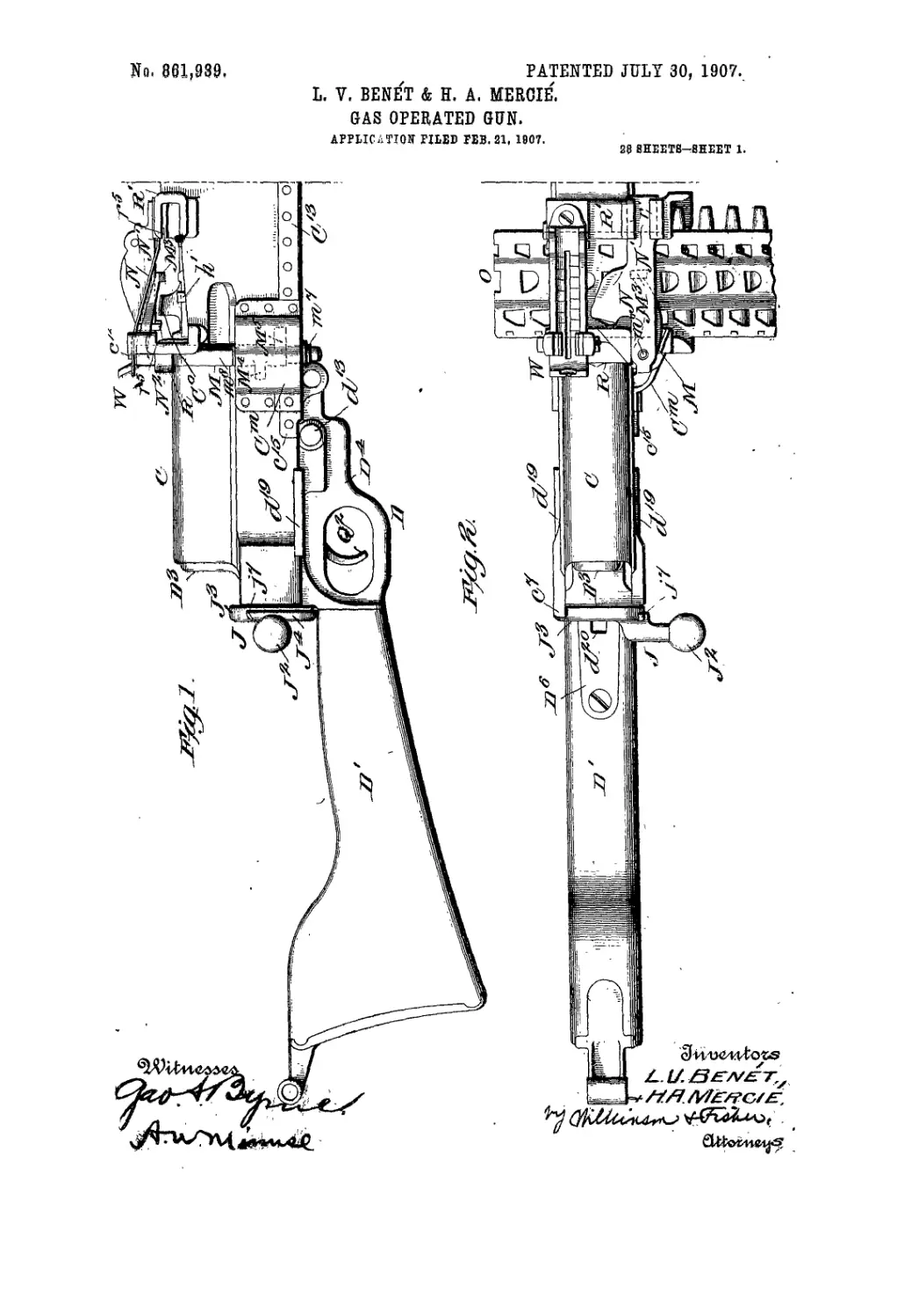
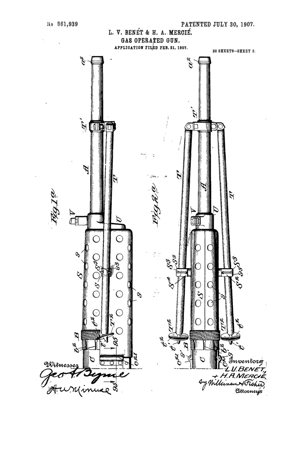
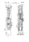
Figures 1 and 1" show the gun in side elevation, the
cartridge strip being omitted. Figs. 2 and 2“ show the
gun in plan, with Lhe cartridge strip broken away.
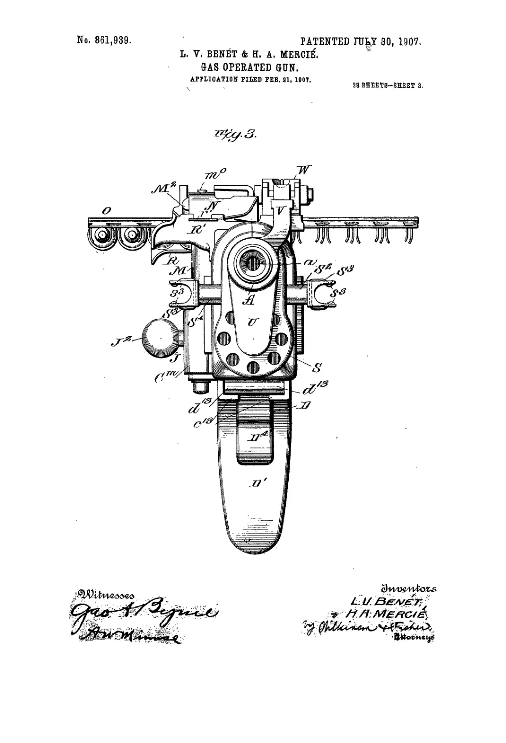
30 Fig. 3 is a front elevation of the gun as seen from the
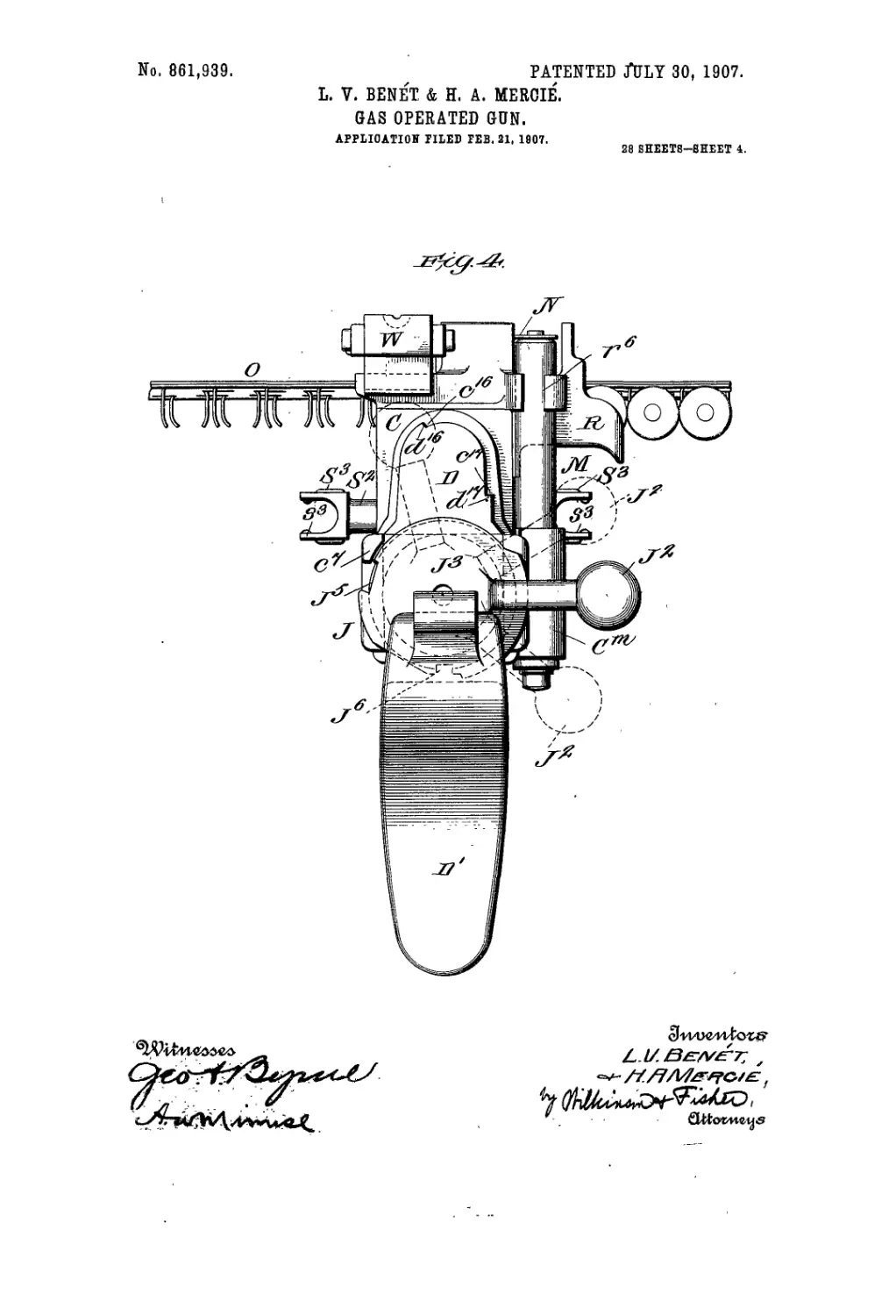
muzzle. Fig. 4 is a rear elevation of the gun, as seen
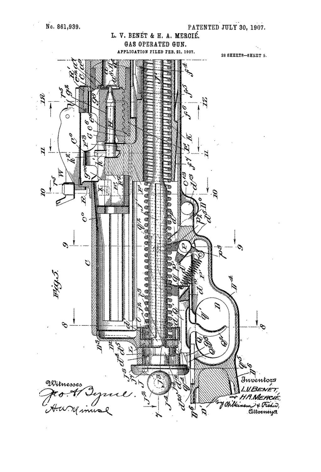
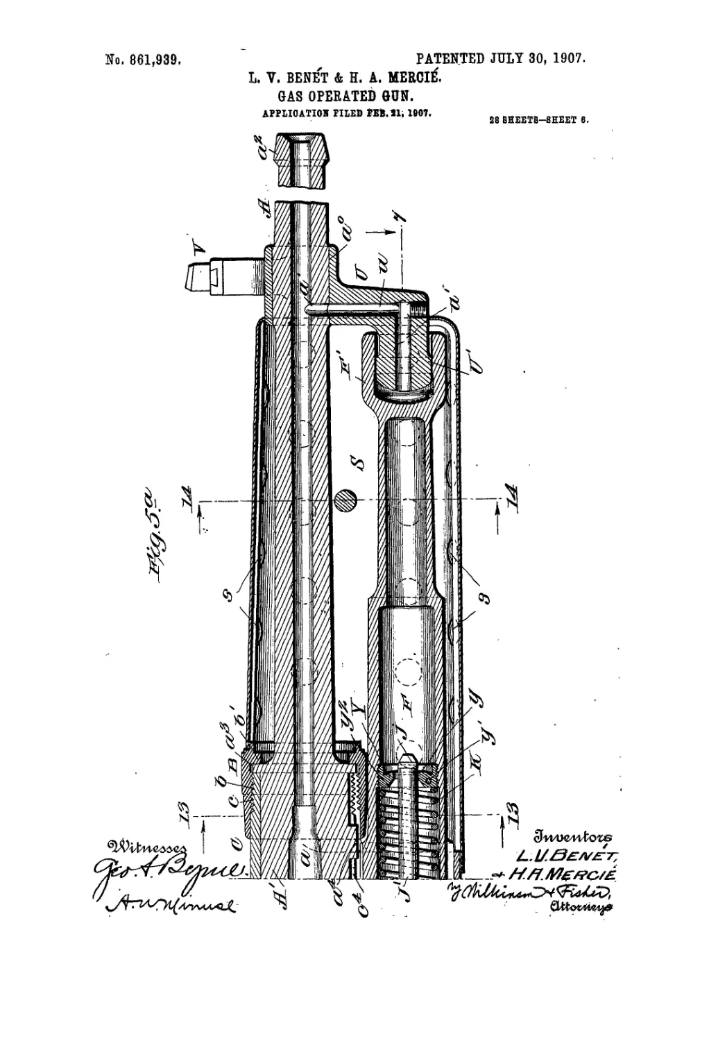
from the breech. Figs. 5 and 5“ show a central vertical
section through the gun, the parts being drawn full size.
In these lignns tlie barrel and stock of the gun are
35 broken away, and the cartridge strip is omitted. In
these two figures the breech ini’Chan ism is shown in. the
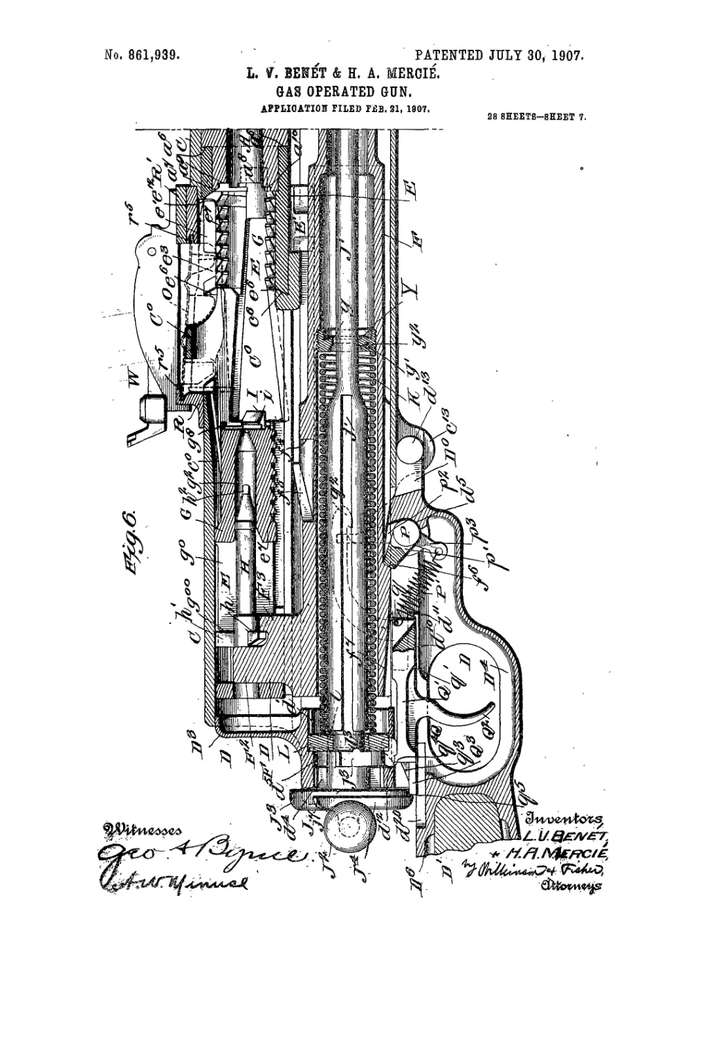
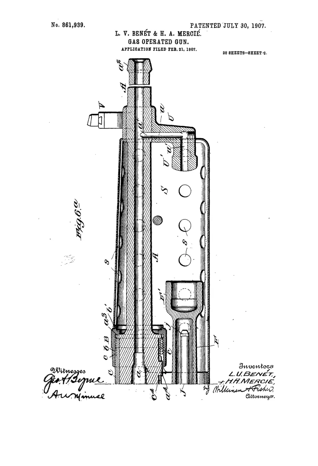
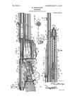
closed and locked position. Figs, 6 and 6“ are similar
to I‘'igs. 5 and 5’1, except that the breech is open, and
the gas operated piston is in |he cocked position. In
40 Fig. 6, the cartridge strip is indicated in dotted lines.
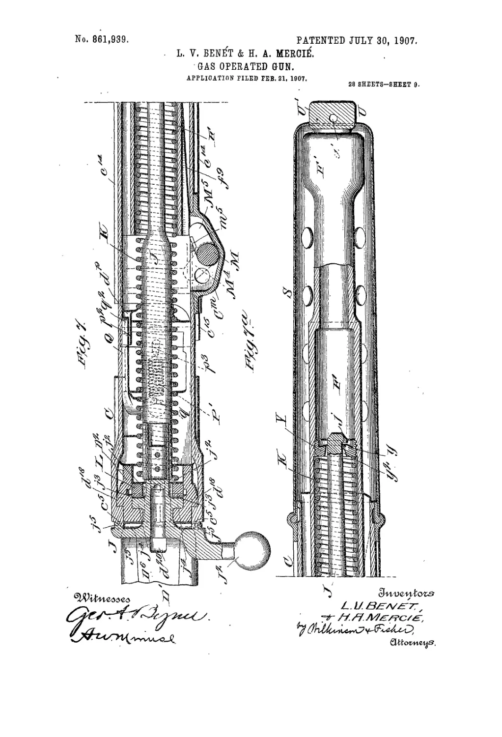
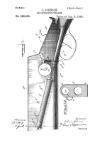
Figs. 7 and 7'* show a horizontal section on the line 7—7
of Figs. 5 and 5“, parts being shown in elevation. Fig.
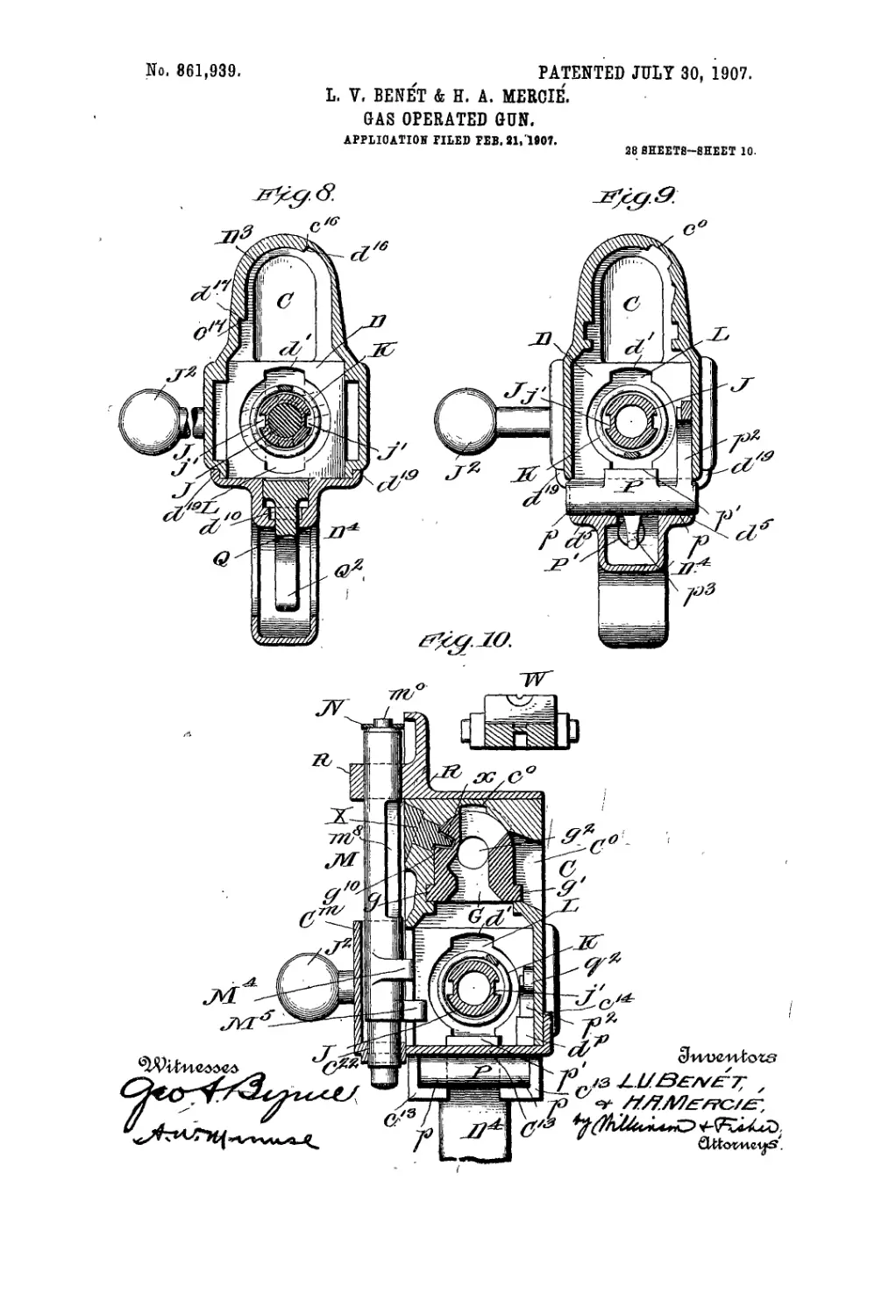
8 shows a section along the line 8—8'of Fig. 5, and
lookiug in the direction of thd arrows. Fig. 9 shows a
45 section along the line. 9—9 of Fig. 5, and looking in the
direction of the arrows.. Fig. 10 shows a section along
the line 10—10 of Fig. 5, and looking in the direction of
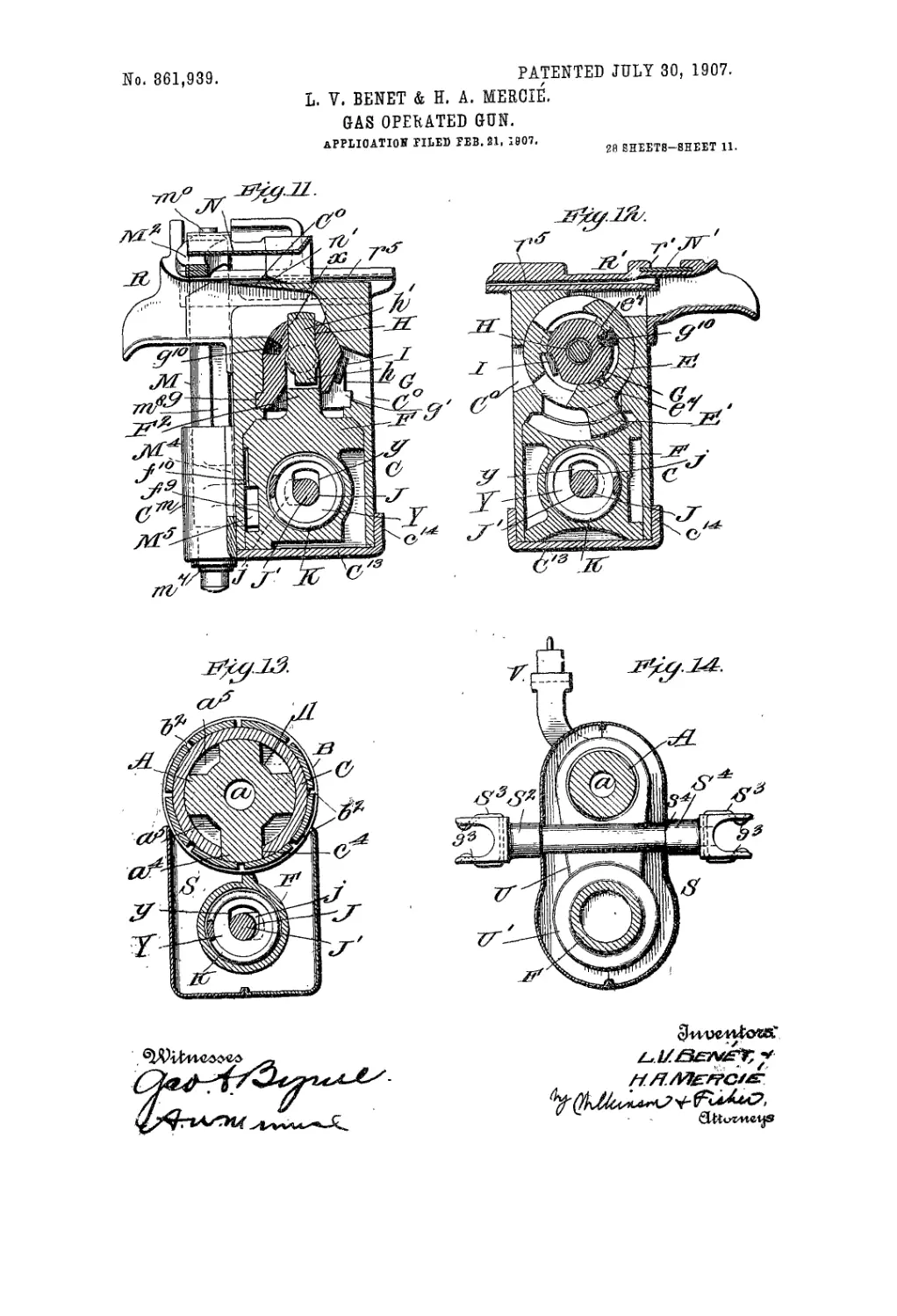
the arrows. Fig. 11 shows a section along the lino
It- II of.Fig. 5, and looking in the direction of the. ar-
50 rows. Fig. 12 shows a section along the line 12—12 of
Fig. 5, and looking in the direction of the arrows. Fig.
' 13 shows a section along the line 13—13 of Fig. 5", and
. looking'in Hie direction of the arrows, and Fig. 14 shows
a section itloilg the line 14—14 of Fig. 5n, looking in the
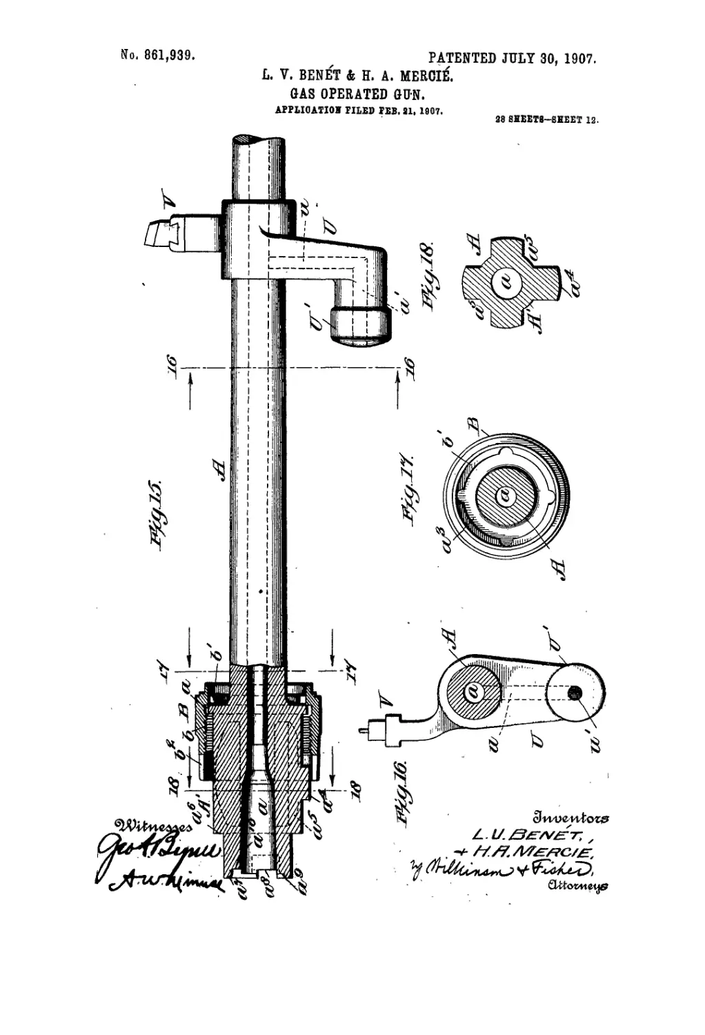
55 ciirecl.ion of the arrows. Fig. 15 isaside elevation of the
barrel detached from the gun, parts being broken away.
Fig. 16 shows a section along the line 16—16 of Fig. 15,
and looking in the direction of the arrows. Fig. 17
show’s a section along the line 17—17 of Fig. 15, and
looking in the direction of the arrows, and Fig. 18 shows 60
asostion along the line 18—18 of Fig. 15, and looking in
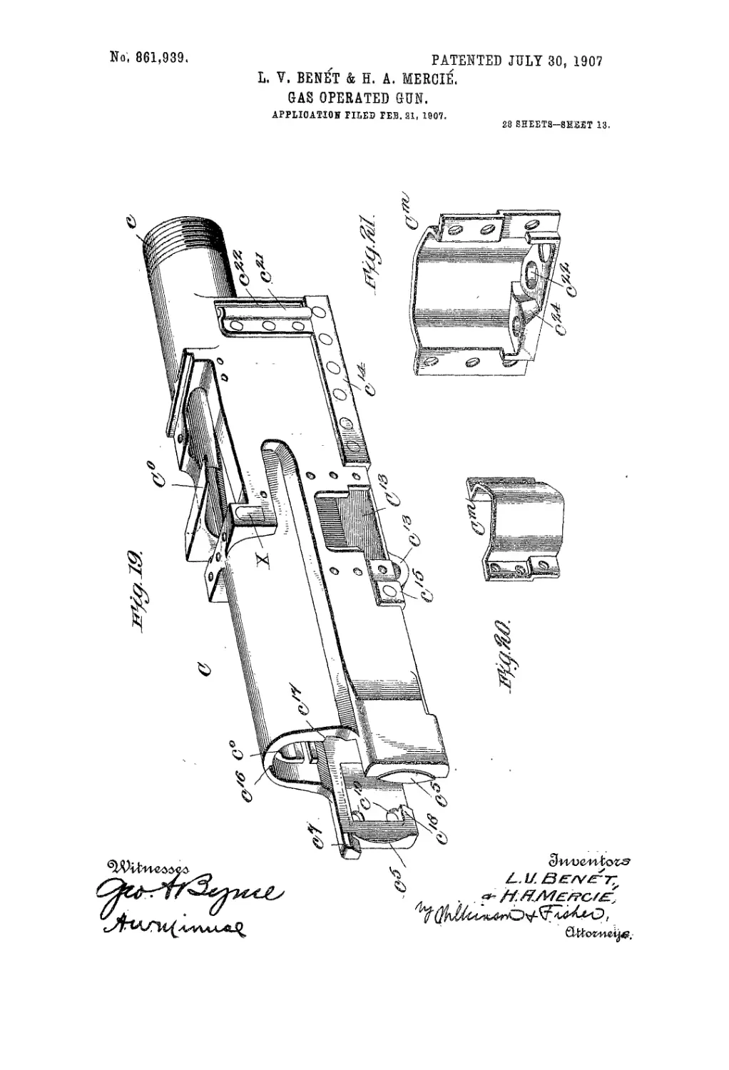
the direction of the arrows. Fig. 19 is a perspective
view of the receiver detached from the gun, parts nor-
mally secured to and forming part of the receiver being
omitted for the sake of clearness in Lhe. drawings. Fig. 65
20 is tV detail perspective view of the lower feed piece
support, detached from the receiver. Fig. 21 is an in-
terior view on a larger scale of the device shown in Fig.
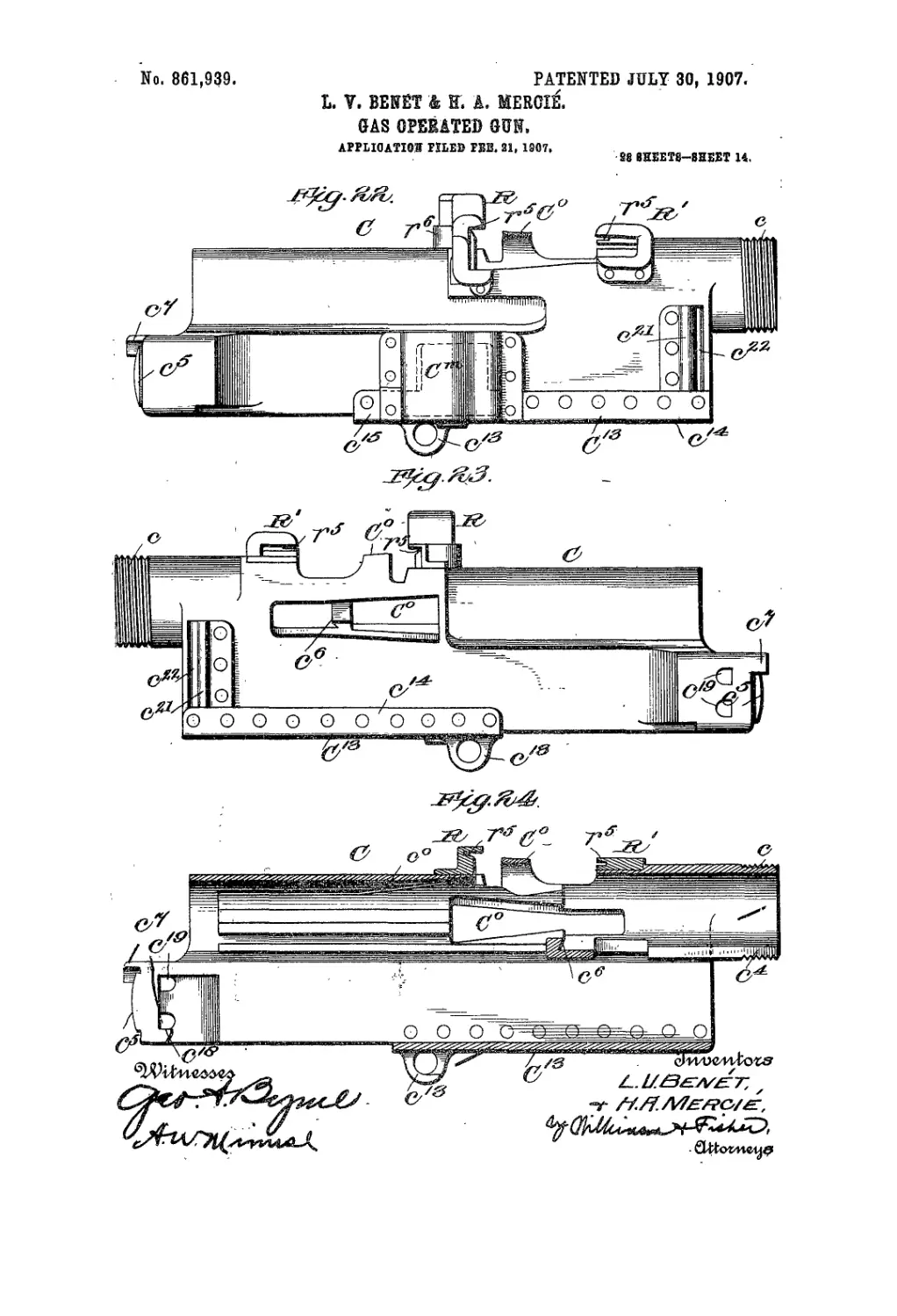
20. Fig. 22 is a side elevation of the receiver on a
smaller scale, the parts omitted in Fig. 19 being shown 70
as applied in this figure. Fig. 23 is a side elevation of
the receiver, as seen from the opposite side from that
indicated in Fig. 22. Fig. 24 shows a central longitu-
dinal vertical section through the receiver, the operat-
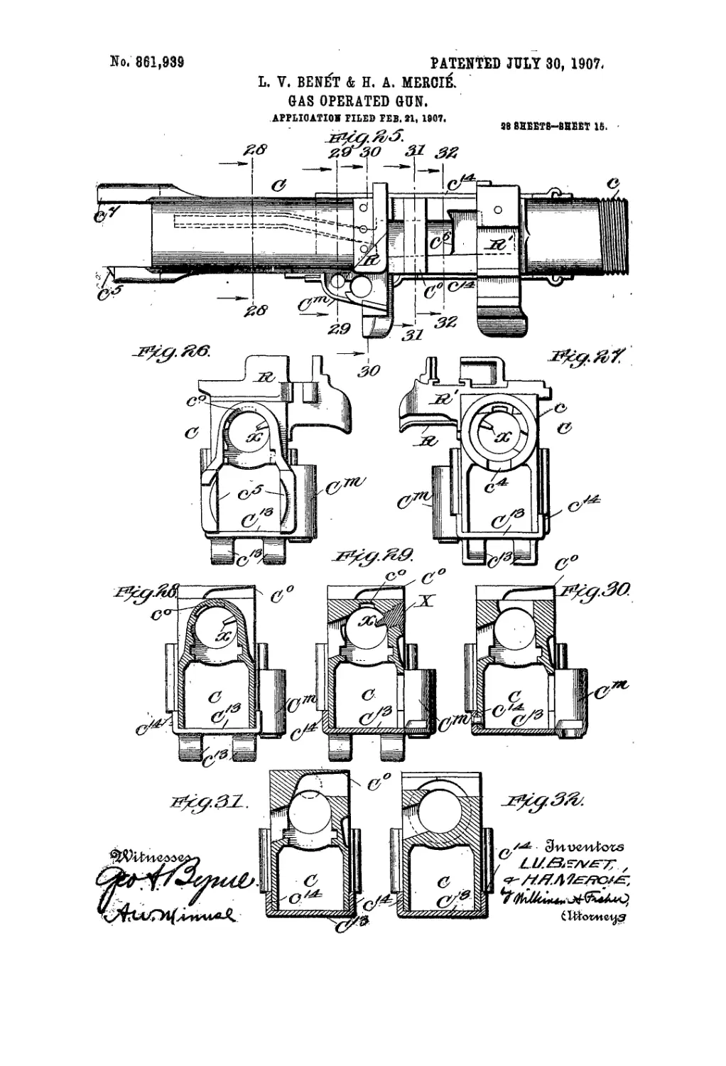
ing parts inclosed therein being-all omitted. Fig. 25 75
shows a plan view of the receiver, as shown hi Figs. 22
to 24. Fig. 26 is an end view of the receiver, as seen
from the rear. Fig. 27 is an end view of the receiver, as
seen from the front. Fig. 28 shows a cross section of the
receiver along the line 28—28 of Fig. 25, looking in the 80
direction of the arrows. Fig. 29 shows a cross section .
through the receiver along the line 29—29 of Fig. 25,
looking in the direction of the arrows. Fig. 30 shows a
cross section through the receiver along the line 30—30
of Fig. 25, looking in the direction of the arrows. Fig. 85
31 shows a cross section along the line 31—31 of Fig.
25, looking in the direction of the arrows, and Fig’.
32 show’s a cross section along the line 32—32 of Fig.
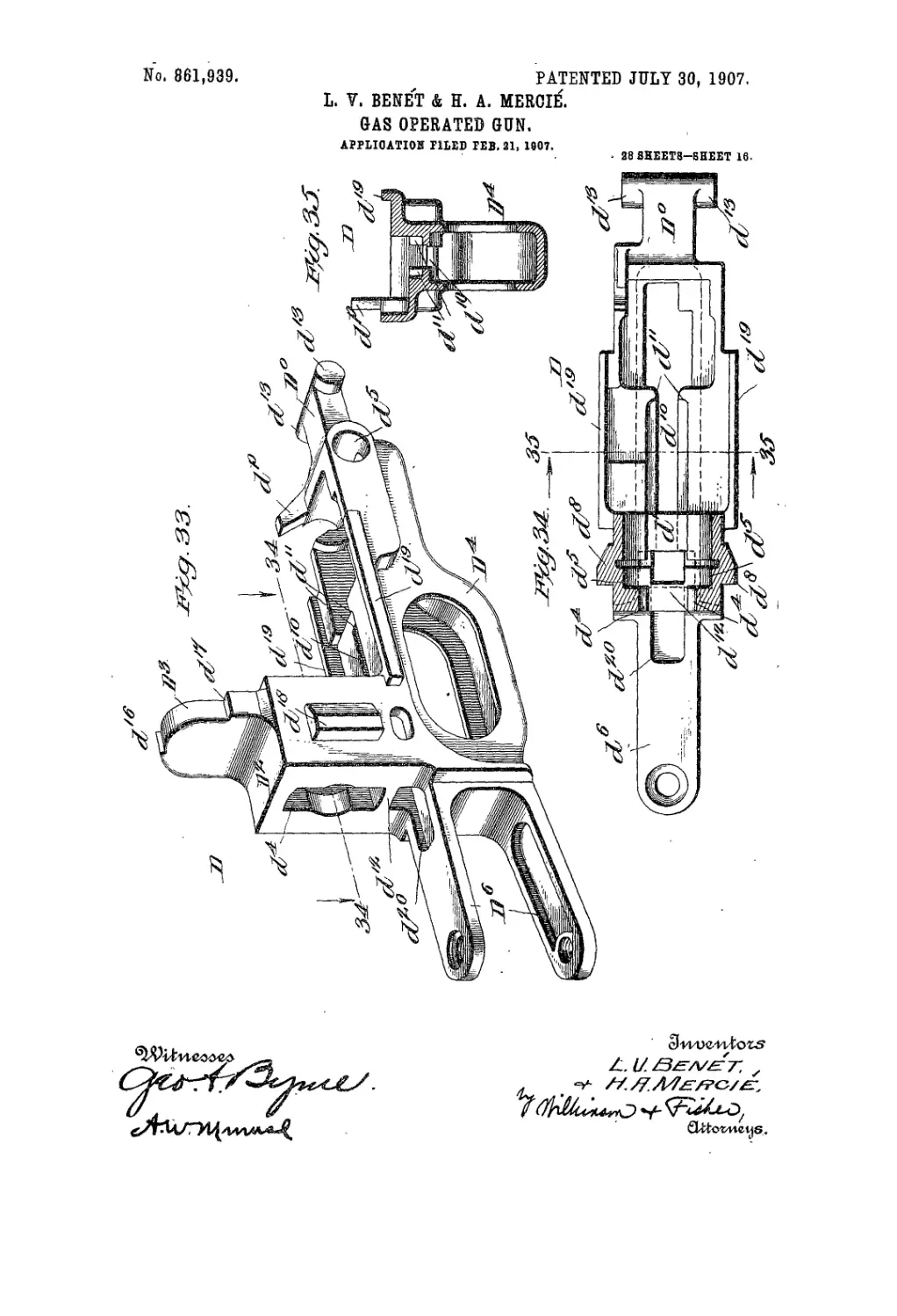
25, looking in the direction of the arrows. Fig. 33 is a
perspective view of the shoulder piece detached 90
from the gun. Fig. 34 shows a horizontal section
through the upper part of the shoulder piece and look-
ing down, the horizontal section being taken through
' the line 34—34 of Fig. 33. Fig. 35 shows a cross section
along the line 35—35 of Fig. 34, and looking in the direc- 95
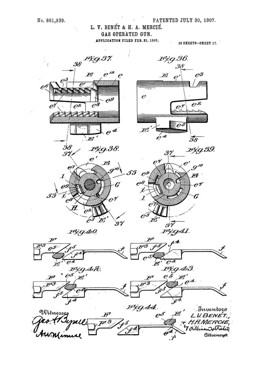
tion of the arrows. Fig. 36 is a side elevation of the
breech nut. Fig. 37 shows a section through the breech
nut along the line 37—37 of Figs. 38 and 39. Fig. 38
shows a section along the line 38—38 of Figs. 36
and 37, and looking in the direction of the arrows. 100
This figure also shows the breech block, firing pin and
extractor in section, the breech block being in the
closed and locked position. Fig. 39 is a similar view to
that shown in Fig. 38, except that the firing pin is with-
drawn and the breech block is in the unlocked position. 105
Figs. 40 to 44'show yarious relative positions of the op-
erating lug on the breech nut, and the cam faces on the
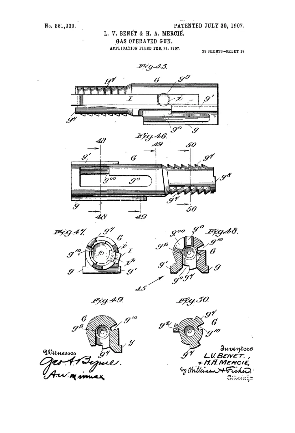
gas operated piston. Fig. 45 shows an. elevation of the
breech block, looking at an inclination upward, as indi-
cated by the arrow 45 in Fig. 48. Fig, 46 shows a top- 110
2
861,936
plan of the breech block. Fig. 47 is a front view of the
breech block. Fig. 48 shows' a section through the
breech block along the line 48—48 of Fig. 46, and look-
ing in the direction of the' arrows. Fig. 49 shows a sec-
5 tion through the breech block along the broken line
49—49 of Fig. 46, and looking in the direction of the ar-
rows. Fig. 50 shows a section through the breech block
along the line 50—50 of Fig. 46, and looking in the direc-
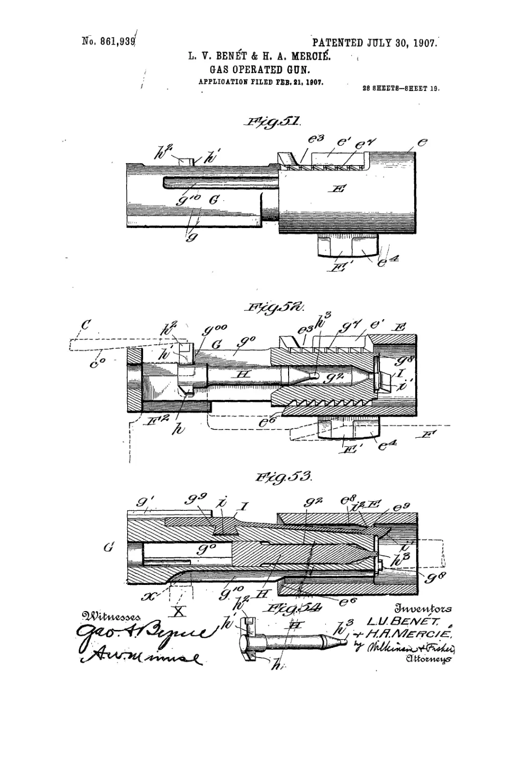
tion of the arrows. Fig. 51 show’s a side elevation of the
.0 breech nut inclosing the breech block, the two being in
the unlocked position. Fig. 52 shows a central vertical
section through the parts shown in Fig. 51. Fig. 53
shows a section through the breech nut and- breech
block, firing pin and extractor, showing the breech
Г5 closed and locked, this section being taken along the
line 53—53 of Fig. 38, and looking in the direction of
the arrows. Fig. 54 is a detail perspective view of the
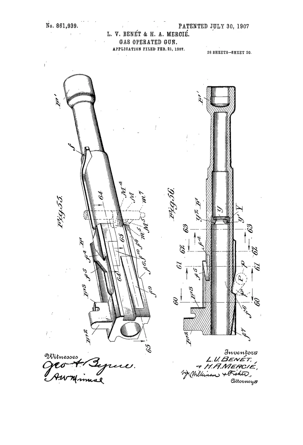
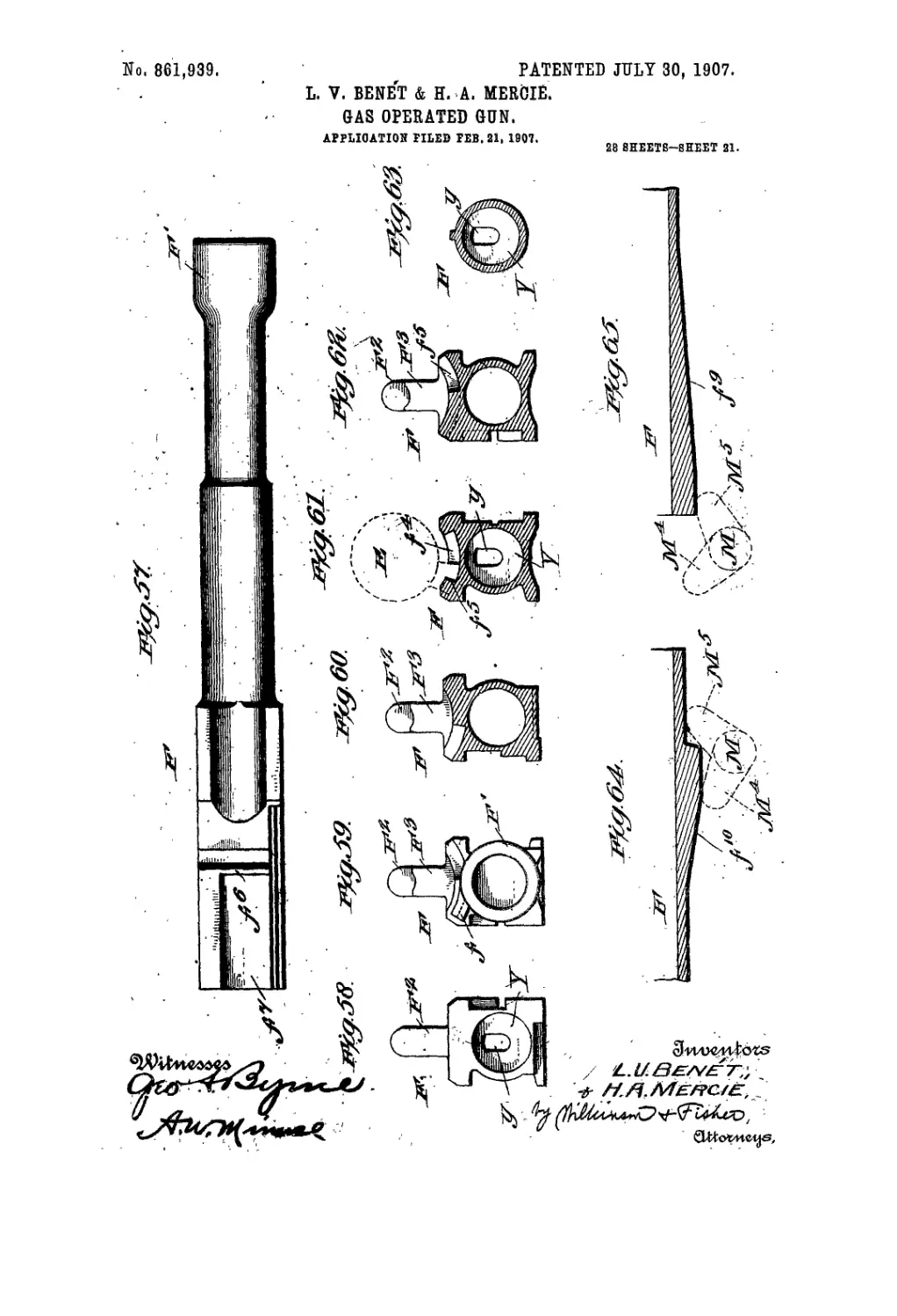
firing pin detached from, the gun. Fig. 55 is a perspec-
tive view of the motor piston, with the feed piece
20 shown in dotted lines. Fig. 56 shows a vertical central
section through the motor piston with the cocking toe
shown in dotted lines. Fig. 57 is an inverted plan
view of- the motor piston. Fig. 58 is a rear view of the
motor piston, as seen from the left of Fig. 56. Fig. 59 is
25 a front view’ of the motor piston, as seen from the right
of Fig. 56. Fig. 60 shows a section through the motor
piston along the line 60—60 of Fig. 56, and looking in'
the direction of the arrows. ' Fig. 61 shows a section
through the motor piston along the line 6]—61 of Fig. 6,
30 and looking in the direction of the arrow's. It also
shows the outline of the breech nut in dotted lines.
Fig. 62 shows a section through the motor piston along'
the line 62—62 of Fig. 56, and looking in the direction
of the arrows, and Fig. 63 shows a similar section along
3 5 the line 63—63 of Fig. 56, looking in the direction of the
arrows. Fig. 64 shows a horizontal section along the
line 64—64 of Fig. 55, with part of the feed mechanism
indicated in dotted lines. Fig. 65 shows a horizontal
section along the line 65—65 of Fig. 55, and illustrates
40 the same part of the feed mechanism as is shown in Fig.
61, but the piston is supposed to have moved forward
from the position shown in Fig. 64 to that shown in Fig.
65. In Fig. 65 the piston is in the forward position, and
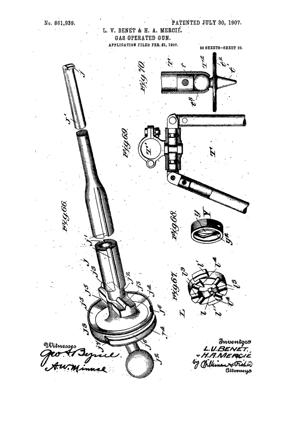
in Fig. 64 it is in the recoiled position. Fig. 66 is a per-
4 5 spective view of the cocking piece, parts being broken
away. Fig. 67 is a perspective view of the supporting
washer in the rear of the gun. Fig. 68 is a perspective
view of the abutment, nnt for engaging the hook of the
cocking piece. Fig. 69 is a detail showing the mount-
50 ing lor the supporting legs, parts being shown in sec-
tion. Fig. 70 is a detail showing the loot of one of the
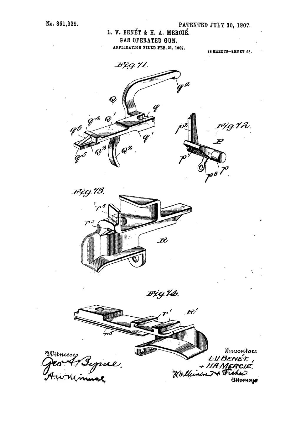
supporting legs. Fig. 71 is a perspective view of the
trigger piece. Fig. 72 is a perspective view of the sear.
Fig. 73 is a perspective view of the rear loading guide,
55 and’Fig. 74 is a perspective view of the front loading
guide, both of which guides are attached to the re-
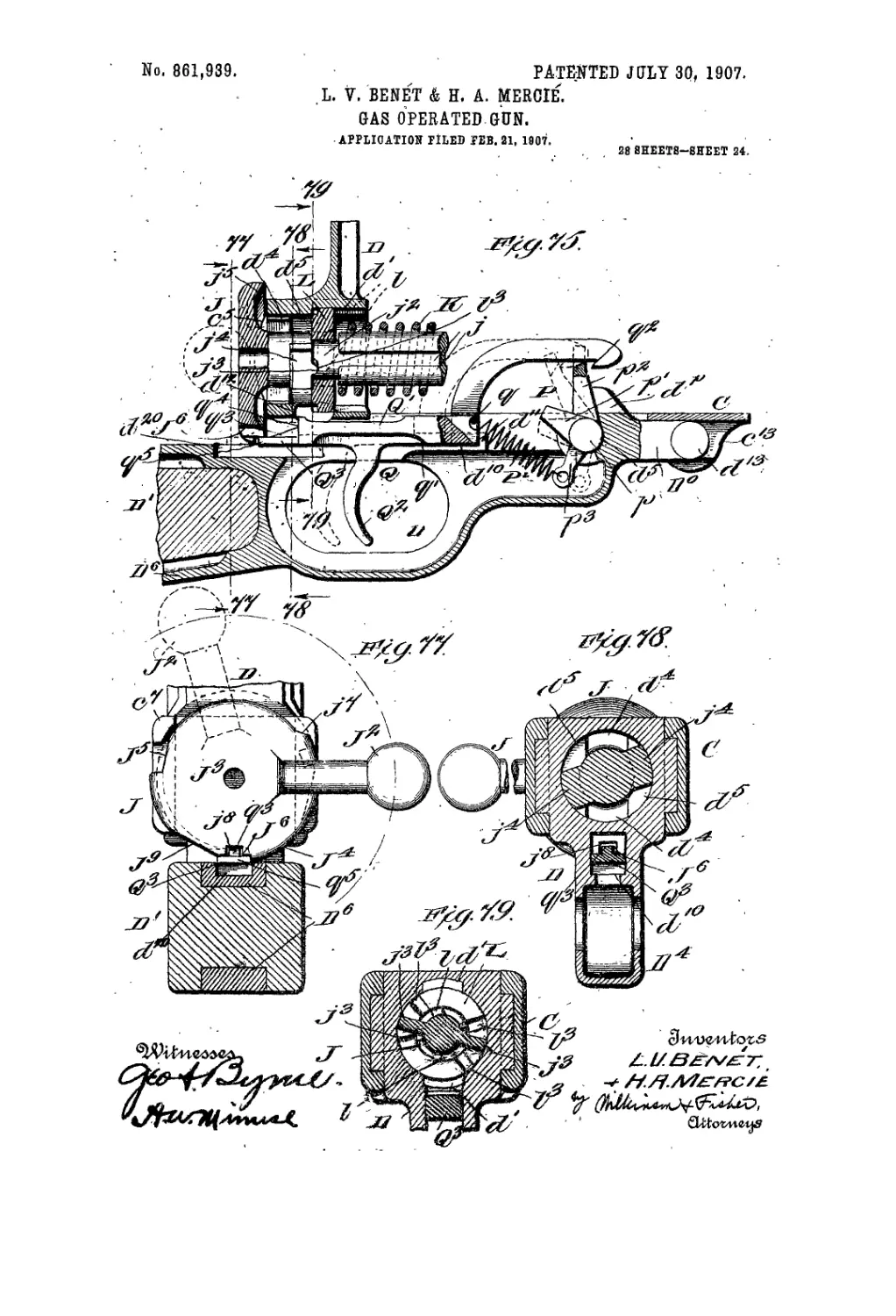
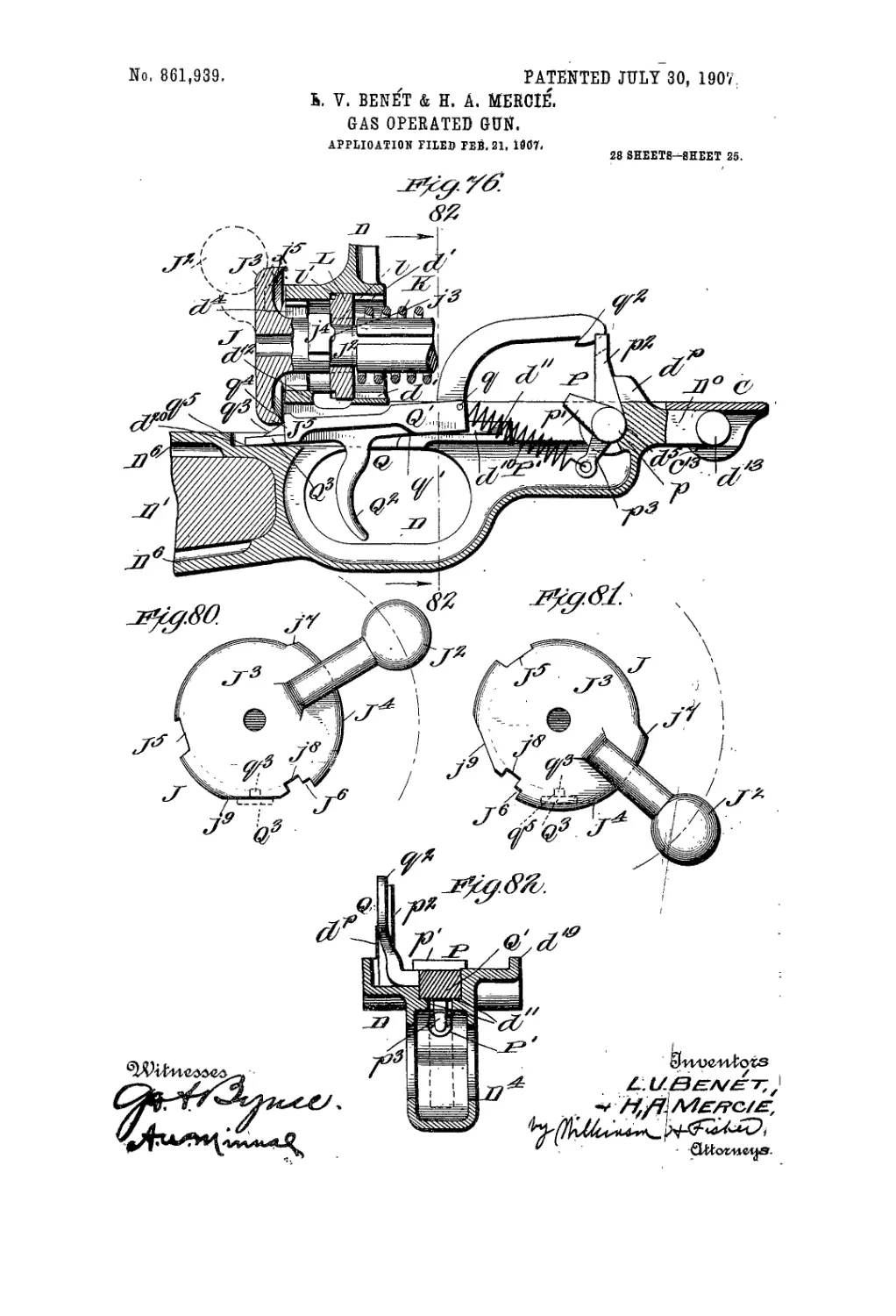
ceiver. Figs. 75 and 76 are vertical sections through
the shoulder piece, and show the trigger mcchailisin in
I wo positions; in Fig. 75 the trigger, shown in full lines,
60 is in the cocked position for automatic firing, and. as
shown in dotted lines, is in the firing position; in Fig.
76, the trigger mechanism is in the position for single
shot firing. Fig. 77 shows a section along the line 77—77
of Fig. 75, looking in the directon of the arrows, and
65 its! -ws, in frill lines, the cocking piece in the position
for automatic firing, and ip dotted lines it is shown in
'the position for assembling. Fig. 78 shows a section
along the line 78—78 of Fig. 75, looking in the direction
of the arrows, and Fig. 79 shows a section along the line
79—79 of the upper part of Fig. 75, looking in the direc- 70
tion of the arrows. Fig. 80 is a rear view of the cocking
piece shown in the'position for single shot firing. Fig.
81 shows the cocking piece in the safety position. Fig.
82 shows a section along the lino 82—82 of Fig. 76, and
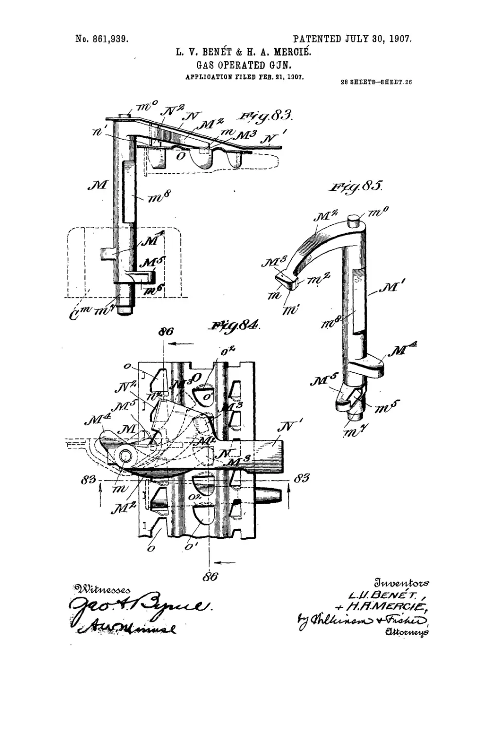
looking in the direction of the arrows. Fig. 83 is a de- 75
tail showing the feed strip and part of the feed mechan-
ism, being a section along the line 83—83 of Fig. 84, qjnd
looking in the direction of the arrows. Fig. 84 is a plan
view of the device shown in Fig. 83. Fig.85 is a detail
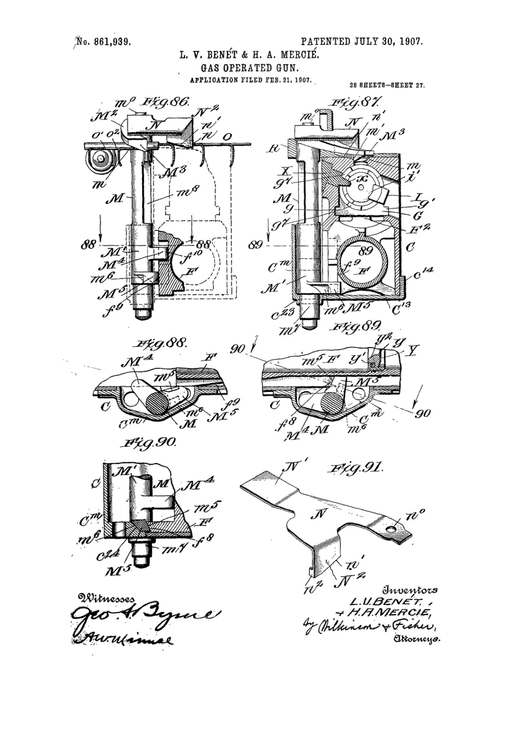
showing the feed piece in perspective. Fig. 86 shows a 80
section on the broken line 86—86 of-Fig. 84, and looking
in the direction of the arrows, part of the breech mech-
anism being shown in dotted linos, and the feed piece
being in the raised or operative position Fig. 87 is a
similar view to that shown in Fig. 86, except that the 85
parts of the breech mechanism are shown in full lines,
and that the feed piece is in the lower position. Fig
. 88 shows a section along the line 88—88 of Fig. 86, and
looking in the direction of the arrow's. Fig. 89 shows a
section along the line 89—89 of Fig. 87, and looking in 90
the direction of the arrows, and Fig. 90 shows a section
along the lino 90—90 of Fig. 89, and looking in the di-
rection of the arrows. Fig. 91 is a detail showing in
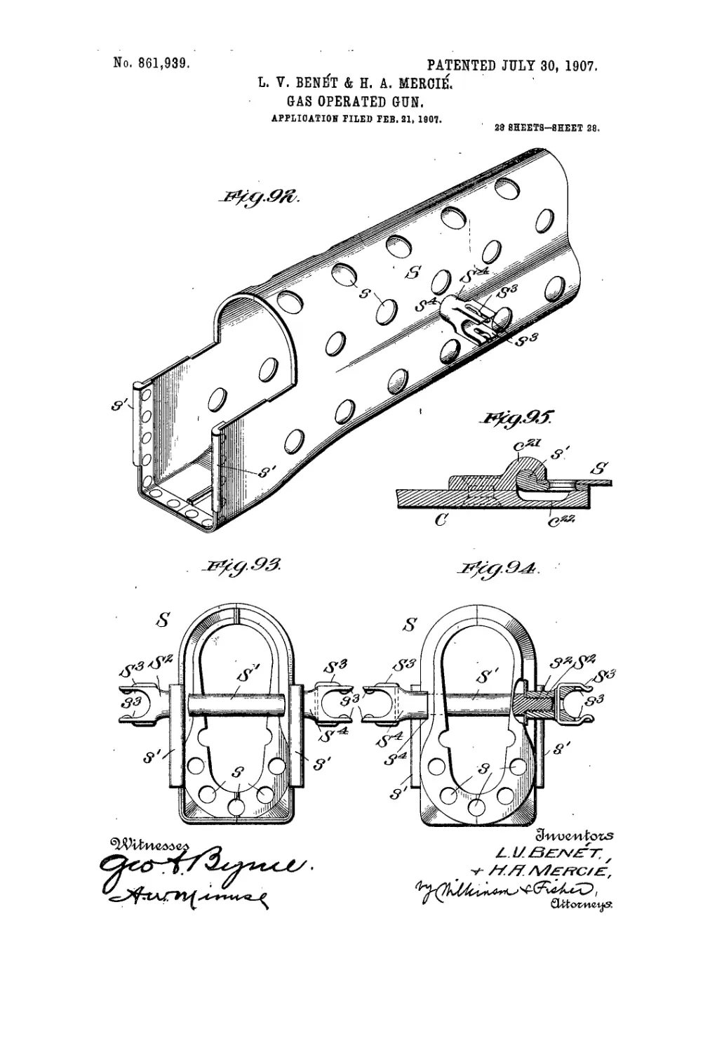
perspective the feed spring. Fig. 92 is a perspective
view of the perforated guard, in which the front end of -95
the motor piston vibrates. Fig. 93 is an end view of the
guard shown in Fig. 92, as seen from the rear, and Fig.
94 is a front view of said guard, parts being broken
away, and Fig. 95 shows a section on an enlarged scale
along the line 95—95 of Fig. 1“, and illustrates the mode 100
of securing the guard to the gun.
Л represents the gun barrel, which is provided with
the enlarged breech portion A' for the powder cham-
ber a, and with a passage a' for part of the powder gases,
see Fig. 5“, and it is also provided with a swell a2, which 105
not, only serves to strengthen the muzzle of the gun,
lint also ma/ be used with a blank firing apparatus of
the type sjhown if) the patent to L. V. Bcn6t, No.
606,115, granted January II, 1898, and entitled gas
operated gitn. The barrel is also provided with, an 110
enlargement a" for the front sight bracket, which will
be hereinafter described. Near the rear end of the
barrel it is provided with an abutment a3, which is held
against the shoulder b' of the lock nut B, which is pro-
vided with screw threads b to engage the screw threads 115
c on the receiver 0. Tims this nut В locks the barrel
and the receiver' firmly together. The barrel is held
against, rotation in the receiver by having a lug a4,
which projects down into a slot c’ in the receiver C, as
shown in Figs. 5“. 6" and 27. Portions of the breech 120
of tin* barrel arc cut away exteriorly, as shown at. tr' in
Fig. 18 to facilitate cooling and to lighten the gun.
The rear part, of the nnt. В is split, as at b2 to form a
spring grip on the receiver C in assembling. The
barrel is also provided with a shoulder ac for the breech 125
nut, is ent away a,t a7 to guide the projectile into the
powder cliainber, and is also cut out at a1' for the extrac-
tor and at. rf1 for the riin of the cartridge case, and for
the nose of the breech block. It will he noted that
the barrel A, the lock nnt B, and the receiver C are 130
861,939
3
rigidly secured together, and the receiver is also rigidly
secured to the shoulder piece D, to which is firmly at-
tached the stock I)'.
The receiver C contains or supports most of the
5 operative parts of the, mechanism, first of which may be
mentioned the breech nut E. This is shown in the
various longitudinal sections through the breach, but
in detail in Figs. 36 to 39, and 51 to 53. This breech
nut is mounted in the receiver co-axial with the barrel,
10 and while the barrel is fixed against rotation, the
breech nut is arranged to rotate about its axis through
a predetermined angle in opening anil closing the
hrcech. It is, however, held (irmly against longi-
tudinal motion, abutting against the. shoulder a1'' of the
15 barrel and against the lug r1' of the re< eivcr, which lat-
ter lug is preferably inclined, as shown in Figs. 5 and
‘6, to engage the inclined face c1' of the breech nut. E.
This breech not is made in the form of a sleeve c in its
forward part, and is slotted longitudinally in its rear
20 part, as at ef to receive the cartridge, and as al, e2 to
permit the cartridge to fall out. It is further ent
away, as.at. e3, to engage a part of the feed strip O,'as
will be hereinafter described. The breech nut E is
provided with a lug E7 having two cam faces f and e',
25 which cause the breech nut to rotate for locking or nn-
locKing the breech block, as will be hereinafter de-
scribed. On the interior of the breech nut. it. is pro-
vided with a buttress thread ё slotted so as to leave
three, full and three blank sectors, and one of the
30 l.'ank spaces is deepened somewhat, as al, es, to permit
the free entry of the extractor, and to the left of which.
• ns shown in Figs. 37 to 39 and Fig. 53. there is a ciim
surface e'1. which causes the’extractor to lock over Hie
rim of the. cartridge case, and grip the same firmly
35 without the necessity for anj’ extractor spring, as will
be hereinafter described.
F represents the motor piston, which carries the
cup-shaped piston head F7, which receives part of the
powder gases through the opening tiz in the barrel, and
40 the passage's « and ,i/ in the bracket U, which bracket
has a boss IF fitting snugly in the cup piston Fz and
clearing the same when the piston has recoiled snlli-
cicntly to the rear, the extreme positions of the cup
piston being shown in Figs.'S'1 and I;'. For conven-
45 ience of manufacture, the bracket U also constitutes a
support for the front sight V. Thwinotor piston is
driven backwards by (lie powder gases :artd is returned
to the initial position by the main spring K. and the
means for operating by hand will be hereinafter de-
50 scribed. 'Flic general shape of the moto?‘piston F is,as
shown iii Figs. 55 to 57. On its upper side it carries
a guide rib f, which engages the lug I<7 on the breech
nut E, and rocks the nut to the engaging position in
assembling the mechanism. In rear of this guide f,
55 two cam faces /* and /' are provided, which engage
the corresponding cam faces F and e,' of the Ing 1'7 of
the'broe.ch nut, and-thus rock this nut to the position
for releasing or holding the breech block. There is a
slight lest motion between this lug and the cum faces
60 and/“• for reasons hereinafter to be explained. The
motor piston is provided wii.ll a lug F-’on ils lice], in
front of which is a yoke F;!, as shown most, clearly ill
Figs. 55 and 56. The breech block G has a slot </" in its
heel, which slips overthislug Freund ihns connects the
65 breech block to the motor piston. The breech block
is provided with guide ribs </ and </. which engage in
corresponding guide grooves in the receiver, and thus
the breech block is free to reciprocate in said receiver,
but is held againsf turning therein. The head of the
breech block is provided with interrupted buttress 70
screw threads r/7 to engage with the similar screw
threads ё of tin’ breech nut. The breech block G is
recessed to receive the firing pin II, which latter
moves with the motor piston, being pros ided with a big
h which engages back oi the yoke F3. This firing pin 75
has a second lug h' having a cam fa< о /г, sec Figs. 5.
6 and 54, which lug h' is free to travel longitudinally
in the slot (/" of the breech block G, but is cammed in-
rear of the shoulder </"" by engagement with the cam
groove Iя in the receiver, see Figs. 5. 6, 10, 19 and 24. 80
Thus it will he seen that the first part of the recoil of
the molor piston will drag the firing pin to the rear,
but. without moving the breech block io the lenr; then
tilt: breech nut will be turned and unlocked about ihe
time that the lug F- on' the motor pi, ton reaches the 85
end of (he slot у" in the breech block, when the breech
block will also be withdrawn to the rear, and thereupon
the cam /г on the lug 7/ of the firing pin will engage the
cam face r," of the receiver and (he firing pin will be
rocked until the lug h' engages the shoulder </lw. by 90
which engagement the breech block will be positively
locked to the motor piston until it returns to this posi-
1 ion on counter-recoil, when the reverse cycle of opera-
I ions will take place.
In Fig. 52 the living pin II is shown in the position 95
just before it begins to rock to lock the breech block
to the molor piston, and in Fig. (i the liring pin is
shown, after being rocked Io the locking position.
Thus it will bo seen that the firing pin always moves
with the motor piston, but that, in the initial operation 100
of opening the breech, and in the final operation of
closing (he breech, the firing pin has a limited lon-
gitudinal travel independently of the longitudinal
movement of the breech block. After this limited
longitudinal movement in opening, the liring pin locks 105
the breech blpck to the motor piston, and the throe
parts so locked together continue rearward during re-
coil, and forward again on counter-recoil, nntilthc cam
face Ji2 strikes the cam groove c" on counter-recoil.
Then the firing pin will be rotated until the lug h' is 110
disengaged from the shoulder at this time the fur-
ther forward movement of the bri'cch block is arrest,cd
by the engagement of the rib </"-on the nose of the
breech block with the rear face if’ of the gnu barrel,
and the. engagement of the lug F/ of the breech nut. 115
with the cam face f* rocks the breech nut to the-
locked position. While this camming is being effected,
the point, Ji" of the firing pin continues to move forward
in I he recess </-’ of the breech block until it strikes the
cartridge and the gim is fired, whereupon the cycle of 120
operations is repeated. The above description applies
to one complete automatic cycle ol operations without,
complies''.ing the same with the feed or extractor mech-
anism, or with the hand operated menus of controlling
the fire. 125
The extractor 1 is provided with a segmental dove-
tail Ing i, which tils in the corresponding socket </" in
the side of the breecl.i block, and this lug is inserted in
said socket in a. transverse position, and then the ex-
tractor is swung to the longitudinal position, after the 130
861,039
5
10
15
20
25
30
35
40
45
50
55
GO
65
manner of a bayonet joint, thus locking the parts firmly
together in the position shown in Fig. 53. The claw
of the extractor is provided with the usual wedging face
i', and on its back is provided with a second cam face
i2,which is adapted to engage the cam r’: on the interior
of the breech nut, when said nut is rotated to the
locked position, and thus this cam presses the ex-
tractor claw firmly down in engagement with the rim
of the cartridge case, as shown in Figs. 38, 39 and 53.
Thus it will-be seen that the claw of the extractor is
free to ride freely over the riin of the cartridge-case and
to snap in front of the same, as the breech block
reaches the forward position, and then is cammed
down hard over the rim of the cartridge case, and can-
not be shaken loose until the breech block is moved
slightly rearward in the breech nut. This will cause
the extractor to hold very firmly during the operation
of starting the empty cartridge case from its seat after
the gun has been fired, but will permit the empty car-
tridge case to bo freely dislodged from such engage-
ment by the ejector mechanism, after the cartridge
case has been withdrawn rearward a, sufficient dis-
tance.
The ejector mechanism comprises a block X secured
in the receiver C, as shown in Figs. 10 to 12, and in
Figs. 26 to 29, which block has a finger x, which pro-
jects into a groove. gw in the side of the breech block,
and this finger strikes the edge of the cartridge case op-
posite to that held by the extractor, when the breech
block is withdrawn and flips' the cartridge case out of
engagement with the claw of the extractor, causing
said cartridge case to be thrown through the opening
C° at one side of the receiver.
J represents the cocking piece, shot,’; in detail in
Fig. 66. This cocking piece is in the form of a rigid
bar or rod, and is provided with a forwardly projecting
arm У, which is provided with a hook j adapted to
pass through the opening у in the abutment nut Y, wli ich
is screwed into the hollow motor piston F, see Figs.
5“, 7*, and 68. This abutment nut is locked in place
by a pin y'. This, abutment nut forms a forward bear-
ing for the main spring K, and in the automatic oper-
ation of tire gun the hook j extends forward of the
abutment nut. and does not affect the reciprocating of
the motor piston, as shown in Figs. 6 and 6'1. But
when this cocking piece is drawn (back by hand, it
pulls back the motor piston and compresses tlie said
spring, thus enabling the motor pi
to the rear by hand, when desired,
breech and cocking the piece. By 1
piece rigid as shown, it may be con
from the rear, passed through and! turned to engage
the abutment nut; while it may ajlso be. as. conven-
iently withdrawn in disassembling the ports. The
firing mechanism will be described fetor.
The diaphragm of the abutment nut is cup-shaped,
as at y2, to guide tlie hook j into the opening y. in in-
serting the cocking piece." This opening у is made
oblong, as ‘shown in Figs. 11 to 13, so that in assem-
bling the hook J may be inserted in tire vertical posi-
tion, and then may be turned through an angle to the
locked position, as indicated in Figs. 11 to 13.
The cocking piece J is provided with two guide
grooves J7 to engage guide lugs I of the supporting
washer L, which is-Slipped ovbf" the hook end of the
thus.opening the
aving this cocking
mnient.lv inserted
cocking piece, and which finally is hold over the cylin-
drical portion p of the cocking piece by means of the
tenons I', which engage in grooves d' in the shoulder
piece D, see Figs. 6, 8, 9, 10 and 67. Thus it will be
seen that this washer forms an end bearing for the 70
main spring K, and is held against turning in the
shoulder piece D. The rear face of the supporting
washer is provided with three sets of radial grooves Z’,
to engage the ribs j3 on the cross piece / integral with
the cocking piece J. By turning the cocking piece 75
slightly, the ribs p will wedge forward the supporting
washer L against the action of the spring K, and the
said ribs may be caused to engage any one of the three
sets of radial grooves I3, thus holding the cocking piece
in any one of .three operative positions, which will be 80
hereinafter described. ,
In order that the cocking piece may be turned
through a limited angle only, the rear face of the sup-
porting washer is inclined away from the perpendicu-
lar shoulders I4, and the ribs p press back the support- 85
ing washer when turned, but bring up against these"'
perpendicular shoulders, and arrest the rotation of the
cocking piece when the limiting angle is reached.
This cross piece / is inserted from the rear in the elon-
gated slot d4 of the shoulder piece D, and is then 90
turned through an angle into the chamber d5 in said
shoulder piece, thus locking the said cocking piece to
the gun, except when it is desired to withdraw same
by hand, in which case it is turned back until the
cross piece / may be withdrawn rearward through 95
said slot d4, which position for assembling and with-
drawing the said cocking piece is indicated in dotted
lines in Fig. 77.
For convenience of turning the cocking piece, a
hand knob J2 is provided. The cocking piece is pro- 10t
vided with a cup-shaped cap J3, which is beveled off,
as at J5, to fit over the beveled faces c° at the rear end
of tho receiver, and thus provide a suitable bearing
for said cocking, piece. The cap J3 of the cocking piece
is provided with a segmental abutment J4, which pro- 105
jects beyond the normal circumference of said cap,
and is provided with an engaging face / to engage the.
trigger piece, as will be hereinafter described, and
also with an end piece /, which engages a stop c7 on
the receiver, when the cocking piece is turned to the 110
position for assembling. The periphery of the cap is
also provided with two slots Jc and J° spaced at an an-
gle frpm each other, as shown in Figs. 80 and 81. The
slot J0'is of the same radial depth as J6, but it is nar-
rower, for purposes that will be hereinafter described. 115
Between these slots J5 and J° part of the edge of the
cap J3 is ent away in a straight line, as at/. The slot
J5 is provided for convenience in assembling the parts,
as shown in dotted lines in Fig. 77.. The slot Jc iapro-
vided for use in automatic firing, as will fie hereinafter 120
described, and the straight edge / is used in single
shot fire, as will be Hereinafter described.
P represents the sear, which is pivoted in the shoul-
der piece, as at p, and is provided with a cocking toe
p', which is adapted to snap into engagement with the 125
cocking shoulder/0, under the action of the spring P7-
Th is sear is provided with a cocking arm p2, which en-
- gages the hook q‘ of the trigger piece Q, which is pro-
vided with a pin q connecting the same by means of
the spring P7 to the arm p3 of the sear piece, and thus 130
861,838
5
the game spring R4 tends to rock the sear about its pivot
and also,to draw the trigger piece forward. The move-
ment of the aear in thelorward position is arrested by a
lug on the shoulder piece; while the trigger piece is
5 stopped in its forward position by the shoulders d11 at
the end of the slot in said shoulder piece. In this
slot the horizontal piece Qz of the trigger piece slides
freely, and at the same time has a slight rocking mo-
tion about the point q', as shown in Figs. 71 and 76.
10 This trigger piece carr ies the trigger Q2 projecting down-
wardly therefrom, and also the tail piece Q3 having the
wedge face g3. and the shoulders q1 and q“.
It will be noted when the cocking piece is turned to,
the safety position, shown in Fig. 81, that the shoulder
15 j" (see Fig, 66) will engage the shoulder g6 at th'e end of
the trigger piece, and will prevent the trigger piece'
from being diawn backhand thus will prevent the gun
from being fired. Now, if the cocking piece be turned
slightly to the left, from the position shown in Fig. 81,
20 to that shown in Fig. 77, this will allow the notch J8 to
register with the tail piece Q3 of tire trigger piece Q, the
rib q3 passing into the groove js and the trigger may be
drawn to the rear, and so long as it is held in this posi-
tion the hook q2 will be held in engagement with the
2 5 cocking arm p2, and the firing will continue indefinitely
as long as the trigger is held back and the gun is sup-
plied with ammunition. Now, if the cocking piece be
turned- still further to the left, to the position shown
in Figs. 76 and 80, the cut away portion f will be clear
30 of the shoulder q5, but will tend to engage the wedge
face q3; and now if the trigger is drawn back, to the po-
sition shown in Fig. 76, the first effect will be to draw
the cocking arm p2 backwards, throwing the cocking
toe p' out of engagement with the shoulder fD of the
35 motor piston, and allowing the motor piston to fly for-
ward under the tension of the spring K. As soon as
the cocking toe p' has released the motor piston, the
further rearward movement of the trigger piece will
rock- the trigger piece about the pivot q' releasing the
40 hook q2 from engagement with the arm p~, and allow-
ing the sear to fly forward, tlio parts then being in the
position shown in Fig, 76. On recoil, the inclined face
/' of the motor piston will rock the cocking toe p' back-
wards until it passes-the shoulder/3, when-the spring
45 P' will snap it into engagement with said’shoulder, and
will hold the motor piston against going forward again
until the trigger is again pulled.
To prevent accidents from premature firing when
the cocking piece is in the position for assembling, in-
50 dicated in dotted lines in Fig. 77, the slot .Is is made
wide enough to allow the swinging up therein of the
tail piece Q3, which will cause the upper portion of the
shoulder g4, above the wedge face g3, to rock up and
engage an abutment d12 on the shoulder piece, and thus
55 Will lock the trigger piece against being drawn further
rearward. Also, if through mistake, the cocking piece
has not been fully returned to the forward position,-it
will be impossible to fire the gun, as the shoulder g4
of the trigger piece will bear against the shoulder </'•’
60 of the shoulder piece. Thus it will be Seen that the
cocking piece has four distinct positions, first, the as-
sembly position; second:, the safety position, in neither
of which two positions can the gun be fired; third, the
position for automatic firing; and fourth, the position
65 for single shot firing, The first, or assembly position,
is shown in dotted lines in Fig. 77, the second, or safety
position, is shown in Fig. 81; the third, or automatic
firing position, is shown in .full lines in Fig. 77; and
fourth, or single shot firing position, is shown in Fig. 80.
In assembling the gun, the barrel is connected to the 70
receiver, as already described, and the front end of the
shoulder piece D is connected to the receiver by a tee
D°, whose tenons d13 engage in hooks c13 secured to the
plate C13 fast to the receiver C, as shown in Figs. 23'.
and 24. This plate preferably has up-turned flanges 75
c14. and c15 secured to the sides of the receiver. The
shoulder piece has an upwardly projecting housing’
D2, terminating in an end piece D3 provided with
shoulders d10 arid d17, and the said housing is provided - .
with tenons d18. The sides of the shoulder piece’are,-80
provided with ribs d19, beneath which is located the
trigger housing D4, in front of which is the bearing D6
for the eear. In rear of the trigger housing is the fork
D° to receive the gun stock D'. The shoulder piece, is ..
also provided with a guide slot d-’° for the trigger piece. 85
In connecting the shoulder piece D to the receiver C,
the tee D° is placed with its tenons d13 just in front of
the hooks c13, and then the housing D2 is swung up into
the receiver until the end piece D3 closes the rear end of - .
the receiver; and the shoulder piece is then drawn 90
back to the final locked position, at which time the
shoulders dle and d17 engage corresponding shoulders
c10 and c17, at the rear of the receiver. The tenone
d13 rest over shelves c18, and the tenons d13 fit snugly
in the hooks c13. Thus the shoulder piece is firmly 95
locked to the receiver, and closes the rear end of said
receiver. It will be evident that the trigger piece,
sear piece, and sear spring should all Remounted in the
shoulder piece before the latter is inserted in the re-
ceiver, and that the several parts may be assembled 10.
without the use of any specialtools.
Secured to the lower right hand side of the receiver
is the feed piece support Cm, shown detached in Fig.
20, and on an enlarged scale from the opposite side in .s.ih
Fig. 21. This feed piece support C™ is secured oppo- 105
site an opening in the side of the receiver, as shown in
Figs. 19, and 29 to 30.
We have so far described the general operation of the
gun exclusive of the apparatus for loading, which will ’Л
now be described. . 110
M represents the feed piece, which is mounted in
lower feed piece support 0™, as shown most clearly in
Figs. 86 to 90, and is pivoted in the rear loading guide
R, as shown in Figs. 1, 2, and 87. This feed piece is
shown' in perspective in Fig. 85 and comprises a vertl- Ilf
cal shaft M' carrying a feeding arm M2 havyngg^feed Ag
lug M3, which is beveled upwards, as $t m, rounded as.
at m', and has an engaging face in2. The vertical shaft
Mz also carries two lugs ML- and M8, both of which have
rounded ends, and tne latter of which is provided with 120
two bevele 4 laces m5 and m8, as shown most clearly in
Fig 90. The feed piece has a lower bearing m7, which
projects down through the socket c23, in the supporting
piece Cm, and the arm M8, when there is no feed strip
itt the gun, will normally drop down to the position 125
shown in Figs. 87, 89 and 90, and in dotted lines in Fig.
55, owing to the pressure of the spring N. When in
this position, the arm M5 will drop in the way of the
cam face fs of the motor piston, and will arrest the for-
ward movement of the motor piston in returning to the 130
а
861,939
5
10
15
20
25
30
35
40
45
50
GO
G5
inilkil position, said linn then being held between the
bevel faces c-'4 andthus holding the motor piston
against further loiward travel Now. however, if the
lend piece In1 tilled, as by inserting a fresh feed strip,
or by hand, then this arm M-’ will be released from
< ngiigemenl with the face./'' of the motor piston, and
t,.v Inlier will return forward io the initial position.
I hut is to rhe breech closed jiosition. The feed piece is
normally pressed downwards causing the arm M2, to en-
gage. as already described, by means of a feed spring
N. shown in Figs I, 2, 36, 87. and in detail in Fig. 111.
This spiing is perforated, as at, n", to slip over the Ing
and its other end Nz is held in guides r'in the for-
ward loading guide IV, see Figs. 1, 2 and 74. This
spring thus tends to press down the feed piece, but it.
also has another function, that is itactsnsa pawl Io pre-
vent the backward motion of the fet'd ship O. 'This
result is obtained by providing a downwardly project-
ing claw N2 having an inclined face n', and a holdi”g
edge h-‘. which latter is projected down into the open-
ings о of the feed strip 0, as shown in Fig. 86, and
while the inclined face n' permits the feed strip to be
fed to tin' right in Fig. 86, the holding face n2 will pre-
vent the feed ship from being withdrawn backwards.
The feed strip is fed forwards by the reciprocaling
motion of the feed arm M-’. As the feed lug M3 swings
forwards from the position shown in Fig. 86, it will en-
gage in oim of the central holes o' of the feed slrip, and
will press against the forward edge o2 of said hole,
pushing ihe feed strip forwards. When the feed arm
oscillates in the reverse direction, tin' bevel face in is
cammed up against the' downward pressure of the spring
N and lifts the feed piece, permitting the same to swing
freely backwards. At the same time the lip N- of the
feed spring N prevchls any back lash of the feed strip
O. The fbed strip О is of precisely ihe same const rue-
lion, us fully described and claimed in our I’alent.
No. Iilli.792, dated April 3. IllOt). but in rise the feed
si rip is t timed upside down, instead of being used in i he
position shown in tin' patent aforesaid. This oscilla-
tion of the feed piece M is effected by the engagement
of the Ings XI’ and Ms with corresponding emus on |lie
molor piston, as will now be described.
Suppose the gnu to be unloaded and the breech
closed: draw the motor piston backward by hand,
using llie cocking piece, uniil it is slightly in ie:ir of
the cocked position, shown in Fig. (>. The distance
between the shoulde.is f" and ./’’' on the motor piston
is so adjusted thill the shoulder/" will engage the arm
Xfs when in the lowered position, slightly before the
cocking loe p' engages ihe slioiiIde)./'. Thus thjs arm
-M ’ of I he feed piece will of ilsdl alone hold the motor
piston in ihe rear position. Now, i| ihe feed is lilted
oil Iler by hand, or by the insi-rl ion of ;i teed slrip. tin-
at in ?1 ’ will be Idled mil ol engagement with I Im shoul-
der/'', and the molor piston will navel slightly lor-
wnrd Io ihe cocked position, shown in Figs, li and 56.
and will then he lovely Io lly loiwurd wlivli the bigger
is pulled So long as Hie feed piece is held in llie
raised posijion, licit is, so long as theie is a leeil slrip
in the gun. Ihe arm XI1 will be lilted elcin of the locking
position, and the molor pi.-iou can only be held in il.
rear position by the cocking toe, and this may be
thrown out of eiig-.igeincni, as already described
Suppose the molor piston to have passed I’min the
jiosition held back by the arm XIs, to the cocked posi-
tion shown in Fig. 6, if the trigger be pulled, the motor
piston will fly forwards'causing the cam /'-' to rock the.
arm M’“ to the jiosition shown in Figs. 8I> and 88, which
will rock the fm'd jiiece and with it. the arm M2 hack 70
to the jiosiliou shown in full lines in Figs. 83 and 84,
in which jiosil.ion the feed lug M:l will project down
into one of the holes o2 in the feed strip and will be
ready to feed the feed strip forward when said feed
jiiece is rocked in the reverse direction, or to the cen* 75
tral position indicated in dotted lines in Fig. 84. This
rocking forward of Che feed Btriji is effected by the en-
gagement of the lug M4 with the cam face/"' on the
motor piston, which cam fuco strikes said lug M1 as the.
piston travels reiirwurd, after the gnn has been fired. 80
/The engagement of these lugs M4 and Ms with the rums
and/9 is showndiugraminatically in Figs. 64 and 65.
Thus it will be seen that the feed piece serves as a
jm.diive lock to the operation of the gun until said feed
piece is either lifted by hand <ir by the insertion of a 85
Iced slrip, and that, the feed sjiring tends to press said
feed jiiece into the lucking jiosition, and it also serves
as a stoji ti> prevent bark lush of the feed strip. To
remove n partially used feed st-rij), it is only necessary
to lift the feed piece slightly by hand. This will nut DO
only lift the feed lug M3 out of engagement, with the
feed striji, but will also lift the claw N2 of Ihe feed sjiring
out of engagement with said feed strip, and ihe feed
strij) may then be bucked out of the gun. For cim-
venience in assembly, I,lie feed jiiece is cut away, us al, 95
ni.s. to pass between Hie jaws r" of the loading guide II,
being then in the jiosition indicated in dolled lines
towards the t.oj> of Fig. 84, and then if the feed Jiiece
be rotated to the right, as shown in said figure, it. will
lie held in jilaee by said jaws. 100
The cartridges are withdrawn scrial.iin. from the feed
strip, by means of the tongue C", which jirojecls be-
tween the bottom of the feed strip and the toj> of the
cartridge, the ends of the feed st rip traveling between
the guides r' in the receiver, and the cartridges full 10u
into the throat of the. receiver to the jiosition shown
in dolled lines in Figs. 6 and 31. when the head of Ihe
carl ridge case is struck by the nose of the breech block,
and the nose of the cartridge is deflected by striking
llie surfaces <12 and а~ of Hie breech nut. and barrel 11 '>
resjiectively, see Fig. 6, and isdirected into the powder
chamber, being jiresscd forward therein in Hie usual
way.
Around the hairel, including the jiowder chamber,
and the jiarls immediately forward thereof, and also 115
indiiding the forward end of the motor piston, u guard
8 is mutinied, which consists of a shell made ol I Inn
metal provided with jiei foral ions s. which shell is
picleiably eomjiosed ol’ two halves seemed together
and tn the gun, as shiftvn in detail in Figs. 1“, 2', 1)2 120
i<> 'll.
Fin'll of Ihe two side members ol' the guard is Jiro-
videtl tvilhn rib./ udajited loengagein a corresponding
sued I r21 at Inched to Ihe receiver as shown in Fig.
Do. 'ГЬе reeeir -r is cut away, as al r'-', (u permit the 125
assembling of the guard. These ribs ./ being inscrlcd
in iheir respectite sockets, and the two forward ends
of the guard being divergent, these two ends are
brought closely along the side of the barrel of (he gnu,
and are locked to the gun by means of the stay bolt S', 130
861,939
*7
which has it screw threaded end s2 to engage a nut'S2
carrying spring clips S:1 projecting into the crotch s:1
integral with said nut., as shown in Fig. 94. The op-
posite end o( the slay bolt S' may be provided with a
5 similar locking arrangement, or it may be provided
with a head S4, shouldered as at s1, to bear against the ,
side of the guard, and with a crotch s:1, and spring dips
S3, similar to those already described. For conven-
ience of assembly, it is preferable to have one head
10 solid with Lhe bolt, and the other screwed on, but both
may be screwed on, if desired. These crotches s:i,
together with (he spring clips S3 serve to hold the sup-
porting legs T, when not in use, as shown in Figs. 1!)
and 29. The forward end of these supporting legs is
15 connected by a universal joint to the grooved band T'
secured to the gnu barrel, as shown in Figs. 1“, 2", and
til); and these legs are preferably pnivided with feel
T2 comprising a holding point I', a guard flange 1-, and
a bait and socket joint I3 held below the stop t in the
20 leg T, which leg is preferably made hollow for the sake
of lightness, as shown in Figs, til) and 70.
The operation of the entire apparatus is as follows:—
Suppose the breech block ami the motor piston to be
iu the forward position with the breech closed, as shown
25 in Figs. 5 and 5“, the,cocking piece to be in the safety
position, shown in Fig. 81, and the receiver to be
cniply of ainmunitioii, as shown in Fig. a. In order to
pul, lhe gun into operation, (urn lhe cocking piece io
lhe position shown in dolled lines in Fig. 77, when
30 lhe hook .7 will engage lhe abiilmeiit nut Y mid the
cocking piece is in the position to be drawn (o lhe rear.
Now draw the cockhigpiece Io tin rear until Hie shoul-
der/1 is slightly in rear of the cocking toe p', and the
lug M’’ of lhe feed piece is in the position to drop into
35 lhe recess before I lie shoulder J* of the motor piston.
This will lock the motor piston slightly in rear of the
cocked position, and lhe cocking piece should be re-
stored to th<‘ forward position. Now, if the feed
strip ho inserted, or if the feed piece be lifted by hand,
40 as for the insertion, by hand, of a single eaitridge, the
Ing M'"' will be raised out of engagement with the slioul-.
dor/' of the motor pislon, and the motor pislon will be
pressed forward by the main spring К until the cocking
loo p' arrests its furl her forward movement. The gun
45 will now remain cocked until the trigger is pulled, but
- the trigger cannot be pulled to the rear until the
cocking piece is rotaled Io one of the operative po-
sitions, that is to one of the positions shown in full
lines in Fig. 77, or in Fig. 80, according as it. may he
50 desired to lire cither antoinalienlly or single shot tire,
as shown respectively in Figs. 75 and 711.
The cocking piece having been turned lo one of tile
operative positions, if the trigger be pulled, the motor
piston will lly forward and will carry the loose car-
55 Iridge in the receiver forward into the powder cham-
ber. Nearthecml of the forward stroke of the motor pis-
lon, the breech block will be arrested by sliiking lhe
rear bice of (he barrel, and lhe fmiller forward move-
ment of I he motor pislon will cause lhe cam lug 17 to i o-
00 talc the breech nut lol he locked position. The breech
block is uncoil pil’d from lhe lii ing pin by lhe engagement
of-the cam <•" with the Ing /7, and lhe firing pin and motor
pistoii are then free to move forward while lhe breecli
block is arrested. Just after the locked position of the
05 breech nut is reached, the further forward movement
of the motor piston will cause the firing pin to strike
lhe primer, exploding the cartridge. In going for-
ward lhe aim M"' will have struck (lie cam/1 of the
motor piston and will have ihrowu the feed lug M3 into
the engaging position for feeding the, feed strip forward 70
during tile return stroke of. lhe motor pislon. When
the gun is fired, part of the powder gases will escape
through the passage a' in the barrel A, and will force
the motor piston rearward against the action of the
spring K. The motor piston in ils rearward movement 75
will first move freely backwards a very short distance,
only far enough to withdraw the point of the firing pin
clear of t he face of lhe breecli block. During this move-
ment the motor piston will have moved far enough to
cause the dim face/1, shown in the initial posilion iu 80
Fig. -ft), lo hare struck the (am face <*, the parts then
being in tin’ posilion shown in Fig. 41. There is a slight
lost motion provided bet ween these cam faces/4 and/5,
and lhe cam faces <-4 and c' for this purpose. Now,
as the piston goes further .rearward, it will rock the 85
breech nut to the posilion shown in Figs. -12 and 43,
when lhe breech nut will be unlocked from the breech
block, and the motor piston, being entirely disengaged
from the cam lug 1'7. moves rearward while the cam
Ing remains in lhe position shown in Fig..44. As the 90
piston goes rearward', it will rock the bring pin and
cause it to couple the breech block to the motor piston,
as already described. As the breech nut is rotated 'to
(he locked position, i( has cammed the claw of the
extractor firmly down over lhe rim of the cartridge case, '95
and in rotating to unlock, (he breech block is moved
slightly rearward, owing to the pitch of the threads
/, and during this movement the cartridge case is
started from its seat, while, .at the same time, the claw
of the extractor is held in firm engagement therewith. Ю0
When the breech nut is wholly unlocked from the.
breech block, the claw of the extractor is also released
from this cam action, but the cartridge ease is then
loose, and is readily drawn .rearward, until the oppo-
sin’ edge of the rim of the cartridge case strikes the Ю5
ejector X, and the empty shell is ejected through the
opening C" in the side of the receiver. As the motor
piston moves rearward, the cam /”1 rocks the lug M4
on the feed piece, and niovre the feed lug M3,’causing
it. to move the feed strip far enough for the tongue
(’“ to tear loose another cart ridge.
The motor piston keeps on rearward until it reaches
the rear limit of its travel: when it immediately starts
t.o return, if the firing mechanism is in the position for
automatic firing, or it is arrested by the cocking toe, 115
if the tiring mechanism is iu the position for single shot
liring, as has already been described. When the pis-
ton continues on forward, after passing the cocked po-
sition, tjie cam /” will strike the lug M5 on the feed
piece, and will rock said feed piece, causing the feed 120
lug M3 to engage the feed strip, ready for another step
forward, when lhe piston recoils again. The cycle, of
operations may be repeated indefinitely. It will be.
noted lliat as soon as the feed strip is exhausted and
falls t.o the ground, the feed piece will be pushed down- 125
ward by the feed spring; and after the last cartridge ;
has been fired, the motor piston will lie Jield back by
the engagement of the shoulder /“ and the arm M5.
This will lock the gnu against being fired, but with the
motor piston in the rearward position. Upon the in- 130
a
; 861,93'9
5
JO
15
20
25
30
35
40
45
50
55
GO
65
portion of a fresh feed strip, the automatic firing will be j
resinned. > j
To dismount or assemble the parts: After having j
made certain that the breech is closed, remove the
cocking pie^e J by turning it from i ight t:> к ft until it ;
strikes its abutment on the receiver. Grasp the han-
dle J2 and draw it upwards and to the rear, in o.div to
free the hook J from its engagement with the abutment
nut Y, which is screwed in the piston; the cocking
piece inr.y now be entirely withd йп. Push the
shoulderpiece D forward in order to overcome the pres-
sure of the main spring K, and at tin' same* time cause
it to pivot downwards about the trunnions d13. The
tenons may now be disengaged from the receiver
and the shoulder piece may be entirely removed- ।
Now, withdraw the main spring K, the piston F, the
breeth block G, and the firing pin II. In order to dis-
mount the feed mechanism, first‘of all, free the feed
spring N by disengaging the hole nl) from the upper
end of the. shaft of the feed piece and remove it. Raise
the feed piece M until the flattened portion ?nH may
be passed through the slot r° in its journals and remove
the feed piece. To dismount the. barrel, first remove
the casing S by unscrewing the assembling bolts S2.
Unscrew the locking nut B, when the. barret A may be.
removed. Once the barrel is removed the breech nut
E may‘be withdrawn from the receiver. From the
shoulder piece remove the trigger, the scar, the sear
spring, apd the supporting washer of the main spring.
To remove the extractor from the breech block disen-
gage its claw from the guide mid turn the extractor
about its pivot g* until the latter is free from its seat.
In order to assemble the gun proceed in'.iiiversc order.
It will be noted that the various parts may be dis-
mounted and assembled without the necessity for any
special tools whatever, and that the frame of the gun,
including the receiver, shoulder piece, stock, barrel,
and guard S, are all rigidly and securely connected to-
gethef.-
It will be obvious that various modifications might
he made which could be used without departing from
the spirit of our invention, and we do not mean to
limit ourselves to precise details of construction, or to
precise arrangements or combinations of parts.
Having thus described our invention, what we claim
and desire to secure for Letters Patent of the Unit, d
States, т :—- v
1. In !i gun. the combination with n gun barrel and a
reciprocating breech block provided with Inferrupted screw
threads, of a breed! nut revoluhly mounted in rear of snid
'barrel but held against longitudinal motion, said breech
\ut being provided with interrupted screw threads regis-
tering with I hose of the breech block, and means for ro-
ll! ling на hl breech nul lo cause Its threads to engage and
disengage with those of the hreecli block, substantially as
described.
2. in a gun, the combination with a gun barrel and a
reciprocating breech block provided w^fth lnterrupled screw
I 'ads, of a breech nut evolubly mounted hi rear of said
barrel but held against longitudinal motion, ^suld 'breech
nut being provided with Interrupted screw threads regis-
tering with t^Oi.e of the breech block, ni}d automatic means
for Votathig said breech nut to cause lt<? threilds to en-
gage and disengage with those of the breech block, sub-
stantially as described.
3. ^In a gun, the combination with a gnu barrel and :t
reciprocating breech yock piuvkled with Interrupted screw
threads, of a breech ntkt reyolubly mounted in rear of said
barrel but held ugalnst longitudinal 4motiou, said breech
nut being provided with Interrupted screw threads regls- 70
lei Ing with those of the breech block, and automatic means
for rohillng snid breech nul to cause Its threads to en-
gage and disengage wilh those of the breech block, com-
prising a motor piston and a cam engagement between
said lr.olor piston and said breech nut, substantially as 75
described.
4 Tn an nntoinalk* gun, I he conil.itiai Ion wilh a gun
barrel and a longitudinally movable breech block provided
with interrupted screw threads, of a breech uni fevoluld)
mounted in rear of said barrel hut held against long)- B0
ii di >nJ motion, said nut b< hu ji-ncide I with inlvrruptvd
screw thread's regiKleriiig il’i Ihose <d the breech block,
and a reciprocaIing motor pixlon I'lmnecied to said breech
block and engaging said breech nul for rotating same, snb-
s|initially ns described. gij
5. In iiu auiomnllc gun. I he combination wilh a gun
barrel and a longitudinally movable breech block provided
wilh Interrupted screw I breads, of a breech nu( revolidily
mounted In rear of said barrel bu( held mains-i longi-
tudinal motion, so id breech nul being provided wilh In- <jq
terrupled screw Ihre.ids registering wilh I hose of I he
breech block, and a reclprocnI tug uiolor pisluii connected
Io snid breech block and engaging said breech nut for ro-
tating same, with an exlraclor carried by said reciprocat-
ing brorrh block, substantially as described. 95
IL In an nutomnde gun, the combination wilh .1 gun
barrel and n longitudinally movable breech block provided
wilh Interrupted screw threads, of i) breech nut revolnbly
mounted in roar of snid barrel hut held against loimi-
ludinnl motion, snid breech nut being provided wilh In- 100
terruptod screw threads registering wilh ihose of ihe
breech block, a reciprocating motor plslon connected Io
snid breech block and engaging said breech nut for ro-
tating smile, with au extracior carried by said reciprocat-
ing breech block, я nd an ejector pro feeling Into a groove 1 Of
In said breech block and engaging the head of the car-
Iridge case when the hreeeh block is drawn rearward, sub-
stantially as described.
7. In an automatic gun. the. cmubinalion wilh a gun
barrel rigidly held In the frame of Ihe gun. and a reel pro- J 10
eating hollow breech block provided wilh Interrupted screw
•threads, of a breech nut revoluhly mounted In rear of said
barrel, but held against longitudinal motion, said breech
nut being provided wilh In I orru pled screw thre.:ids regis-
lerlng wilh those of the breech block, a tiring pin revoluhly 115
mounted In said breech block and having a limbed longi-
tudinal movement therein and being provided wilh a later-
ally projecting lug. a mo I or plslon having :/liig projecting
upward into said breech block, and having/a longllndluitl
play therein, and engaging snid tiring pin. a cam engage- 120
meat, between said motor plslon and said breech nut for
rotating the latter to the locking posillon relative to said
breech block, and a tlxed cam cimagliig said lug on Ihe
firing pin and rotating Ihe latter to Ihe position for lock-
ing the breech block to Ui<‘ motor piston, substantially as 125'
described.
8. In an automatic gun, the combination with a gun
barrel rigidly held In (he frame ol ibe gun. .and a recipro-
cal Ing hollow breech block provided with Interrupted screw
threads, of a bvcech nut revoluhly mounted in rear of sold ISO
barrel, but held against longitudinal motion, said breech
nut being provided with Inlerrnple.d screw threads regis-
ter ng wi(h those of the breech block, a Jlrlng pin re volubly
mounted in said breech block and having a limited longi-
tudinal movement therein and being provided with a later- 135
ally projecting lug. a motor piston having a lug projecting
upward into snid breech block, and having a longllndinnl
play therein, and engaging said firing pin, a cam engage-
ment between said major plslon and said breech ini! for
rotating the kilter to the locking position relative lo snid IdO
breech block, a lixed cam engaging sale! lug on the tiring
pin and rokiiiUg the hitler lo the position for locking the
breech Glock to llie tinilur plslon, with an extractor carried
by the breech block, and means operated by the rotation
of the breech nut for holding the claw of said exlraclor j 45
tlrmly In engagement with the rim of the'cnriridge ease
during the early pari of the breech opening motion, sub-
stantially :)s described.
9. In an automatic gnn, the combination with a gun bar-
861,939
&
rel rigidly held in the frame of the gun, and a reciprocat-
ing hollow brfeech block provided with interrupted screw
threads, of a breech* nnt revolubly mounted In rear of said
barrel, but held against longitudinal motion, said breech
5 nut IxHng provided with interrupted screw threads register-
ing with those of tlie breech block, a tiring pin revolubly
mounted In said breech block and having a limited longi-
tudinal movement therein and being- provided with a later-
ally projecting Ing, a motor piston having a lug projecting
10 .upward Into said breech block, and having a longitudinal
play therein, and engaging said firing pin, a cam engage-
ment between said' motor piston and said breech nut for
rotating the latter to the locking position relative to said
breech block, a fixed cam engaging said lug on the firing
15 pin and rotating the latter to the position for locking the
breech block to the motor piston, with an extractox: car-
ried by the breech block, and means operated by the rota-
tion of the breech nut for holding the claw of said ex-
tractor firmly in engagement with the rim of the car-
20 fridge case during the early part of the breech opening
motion, and an ejector comprising a fixed tongue projecting
Intb a groove In the side of the breech block, and en-
gaging with the rim of the cartridge case as the breech
block Is drawn rearward, rubstantfally as described.
25 10. In an automatic gun, the combination with the gun
barrel and receiver, and means for rigidly securing the gun
barrel to the receiver, of a breech nut revolubly mounted.
In said recelvei* and held against longitudinal motion In
rear of said barrel, said breech nut being slotted along Its
30 rear portion and provided with interrupted screw threads/
a reciprocating motor piston, a cam engagement between
said motor piston and said breech nnt for rotating the nut,
a reciprocating breech block provided with interrupted
screw threads registering with those of the breech nut and
35 connected to said motor piston, with means for allowing
the motor piston a limited play relative to said breech
block, substantially as described.
11. In an automatic gun, the combination with the gun
barrel and receiver, and means for rigidly securing the gun
40 barrel to the receiver, of a breech nut revolubly mounted
In said receiver and held against longitudinal motion In
reax* of said barrel, said breech nut being slotted along Its
rear portion and provided with Interrupted screw threads,
a reciprocating motor piston, a cam engagement between
45 said motor piston and said breech nnt fox* rotating the nut,
* a reciprocating hollow breech block provided with inter-
rupted screw threads registering with, those of the breech
nut and connected to said motor piston, a firing pin revo-
lubly connected to the motor piston, but reciprocating
o0 therewith and projecting forward through said "hollow
breech block, with means for locking said firing pin to the
breech block and for unlocking same during a predeter-
mined part of the movement of the motor piston, substan-
tially as described.
55 12. In an automatic gun, the combination with the gun
barrel and receiver, and means for rigidly securing the gun
barrel to the receiver, of a breech nnt revolubly mounted
In said receiver and held against longitudinal motion in
rear of said barrel,..said breech nut being slotted along Its
GO rear portion and provided with Interrupted s :mw threads,
a reciprocating motor jHston, a cam engagement between
said motor piston.and said breech nut for rotating the nut,
a reciprocating breech block provided with interrupted
screw threads registering with those of the breech nut and
65 connected to «ald0 motor piston, with means fox* allowing
the motor piston oa limited play relative to said breech
block, a resilient extractor carried by said breech block,
and a cam engagement between said extractor and said
breech nut for binding the claw of the extractor firmly
70 over the rim of the cartridge case during the period of
starting the cartridge case from Its seat, substantially as
described.
13. In an automatic gun, the combination with the gun
barrel and receiver, and means for rigidly securing the gnn
75 barrel to the receiver, of a breech «nut revolubly mounted
In said receiver and held against longitudinal motion
rear of said barrel, said breech nut being slotted along its
rear portion and provided with Interrupted screw threads,
a reciprocating motor piston, a cum engagement between
30 Bald motor piston and sa’d breech nut for rotating the nut,
a reciprocating hollow breech block provided with Inter-
rupted screw threads registering with those of the breech
nut and connected to said moto11 piston, a firing pin revo-
lubly connected to the mo I or piston, but reciprocating
therewith and projecting forward through said hollow 85
breech block, with means for locking said firing pin to the
breech block and for unlocking same during a predeter-
mined part of the movement of the motor piston, a resjll-
ent extractor carried by said breech block, and a cam en-
gagement between said extractor and said breech nut fol* 90
binding tlie claw of the extractor firmly over the rim of
the cartridge case during He period of starting the car-
tridge case from its sent, substantially as described.
14. In an automatic gun, the combination with the gun
barrel and receiver, and means for rigidly securing the gun 95
barrel to the receiver, of a breech nut • «volubly mounted
in said receiver and held against longitudinal' motion in
rear of said barrel, said breech nut being slotted along Its
rear portion and provided with interrupted screw threads,
a reciprocating motor piston, a cam engagement between 100
said motor piston and said breech nut for rotating the nut,
a reciprocating breech block provided with interrupted
screw threads registering with those of the breech nut and
connected to said motor piston, with means for allowing
the motor piston a limited play relative to said breech 105
block, a resilient extractor carried by said breech block,
and a cam engagement between said extractox* and said
breech nut for binding the claw of the extractor firmly
over the rim of the cartridge-case during the period of
starting the cartridge case its seat, with an ejector 11C
secured in said receiver and t&oji>£ting Into4 a groove lu
the breecli block on its opposite Side from the extractor,
and adapted to strike the rim dir the cartridge case as the
.breech block is drawn rearward,'Substantially as described.
15. Tn an automatic gun, the combination with the gun 115
barrel and receiver, and means for rigidly securing the gun
barrel to the receiver, of a breech nut revolubly mounted
In said receiver and held against longitudinal motion In
rear of said barrel, said breech nut being slotted along its
rear portion and provided with interrupted screw threads, 120
a reciprocating motor piston, a cam engagement between
said motor piston and said breech nut for rotating the nut,
a reciprocating hollow breech block provided with Inter-
rupted screw threads registering with those of the breech
nut and connected to .said motor piston, a firing pin rev- 125
olubly connected to the motor piston, but reciprocating
therewith and projecting forward through said hollow
breech block, with means fox* locking said firing pin to the
breech block and for unlocking same during a predeter-
mined part of the movement of the motor piston, a reslll- 130
ent extractor carried by said breech block, and a cam en-
gagement between said extractor and said breech nut for
binding the claw of the extractor 'firmly over the rim of
the cartridge case during the period of starting the car-
tridge case from its seat, with an ejector secured In said 135
receiver and projecting Into-a groove in the breech block on
its opposite side from the extractfiV, and adapted to strike
the rim of the cartridge ease as tkfe“breech block is drawn,
rearward, substantially as described.
16. In an automatic gun, the combination with a reclp- 140
rocating motor piston and breech mechanism operated '
thereby, of feed mechanism also operated by the motor
piston and adapted to hold the motor piston in the rear-
ward^ position and to automatically release the same when
a feed strip is inserted, said feed mechanism comprising a 145
pivoted, feed piece having arms engaging stld motor pis-
ton, and provided with a claw adapted to impart a step
by step motion to the feed strip, substantially as described.
17. In an automatic gun, the combination with a recip- •
locating motor piston and breech mechanism operated 150
thereby, of feed mechanism, also operated by the motor
piston and adapted to hold the motor piston In the rear-
ward position and to automatically release the same when
a feed strip is inserted, said feed mechanism comprising a
pivoted feed piece having arms engaging said motor pls- 155
ton, and provided with a claw adapted to Impart a step by
step motion to the feed strip, with a spring normally press-
. Ing said feed piece down to the position for holding the
motor piston in the rear, but yielding when a feed strip
Is Inserted, substantially as described. jqq
IO
861,939
periphery of the head of Ihe cocking piece, hut to pass 80
under sold cut :iw:iy portions, substantially as described.
25. In an automatic gun, Ihe combination with a motor
piston and a spring for returning the same to ihe Initial
position, of a cocking piece projecting forward Into said
motor piston and provided witii a hook adapted to engage 85
tlie motor piston and to draw the same Io the rear against
the action of said spring, Llie said cocking piece being pro-
vided with a flanged head cut away along ft limited por-
tion of its periphery, means for cocking said motor juston
in the rearward position and for reteasinS-'same by hand 90
when desired, comprising a sear normally-engaging paid
molor piston, a sliding trigger piece adapted to withdraw
said sear from engagement with tlie motor piston, and
having a tail piece adapted to strike against the periphery
of the head of the cocking piece, but to pass under said 95
cut away portions, and a spring under tension connecting
said sear and said trigger piece and adapted to normally
hold said sear In the cocking position and the trigger
piece in the forward position, substantially as described.
2C. A feed mechanism for use In automatic guns of the 100
character described, comprising a pivoted feed jiiece pro-
vided with a plurality of arms rigid therewith, one of
said arms bearing a claw adapted to engage-the feed strip,
of a motor piston provided with cams adapted to engage
two of said arms and to rock said feed piece causing It to 105
impart a step by step motion to the feed strip, substan-
tially as described.
27. A feed mechanism for use In automatic gUns of tiie
character described, comprising a pivoted feed piece pro-
vided with a plurality of arms, one of said arms bearing Ц0
a claw adapted to engage the feed strip, of a motor piston
provided with cams adapted to engage two of said arms
and to rock said feed piece causing it to Impart a step by
step motion to the feed strip, and also provided with a
shoulder adapted io engage one of said arms and lock the Ц5
said motor piston In the rearward position when a feed
strip is not In the gun, substantially as described.
1 28. A feed mechanism for use in automatic guns of the
character described, comprising a pivoted vertically mov-
able feed piece provided with a plurality of arms, one of 120
said arms bearing a claw adapted to engage the feed strip,
of a motor piston provided with cams adapted to engage
two of said arms and to rock said feed piece causing it to
impart a step by step motion to the feed strip, and also
provided with a shoulder adapted to engage one of the 125
arms of the feed piece when the latter Is In the lower
position, substantially as described.
29. A feed mechanism fol’ nse in automatic guns of the
character described, comprising a pivoted vertically mov-
able feed piece provided with a plurality of arms, one of 130
said arms bearing a claw adapted to engage the feed strip,
of a motor piston provided with cams adapted to engage
two of said arms and to rock said feed piece causing It to
Impart a step by step motion to the feed strip, and also
provided with a shoulder adapted to eb gage one of the 135
arms of the feed piece when the latter is In the lower posi-
tion, and a spring normally pressing said feed piece down-
wards but permitting the same to be lifted by the Insertion
of a feed strip, substantially as described^ - .
30. A feed mechanism’for use In automatic guns of the 140
character described, comprising a pivoted vertically mov-
able feed piece provided with a plurality of arms, one of
said arms bearing a claw adapted to engage the feed strip,
a motor piston provided with cams adapted to engage two
of said arms and to rock said feed piece causing It to.Im-
part a step by step motion to the feed strip, and also pro-
vided with a shoulder adapted to engage one of the arms
of the feed piece when the latter Is in the lower position,
and a spring normally pressing said feed piece downwards
but permitting the same to be lifted by the insertion of a 159
feed strip, with a wedge shaped claw on said spring, adapt-
ed to engage the feed strip and lock It against back lash,
substantially as described:
31. In an automatic gnn, the combination with a re- '
ceiver provided with guides for the feed strip, and a horn 155
adapted to tear the cartridges loose from said strip, of a
pivoted feed piece provided with a plurality of arms, one
of said arms bearing a claw adapted to engage the feed
18. In an automatic gun, the combination with a gun j
barrel and a receiver, of means for detachably connecting
said gun barrel to said receiver, a shoulder piece carrying
a stock detachably connected to said receiver, breech mech-
5 anlsm mounted In said receiver, firing mechanism mounted
In said ohoalder piece, a motor pistc’a vibrating In said
receiver and actuating the breech mechanism, and feed
mechanism removably mounted in said receiver, with a
perforated casing composed of two parts hinged to said re-
10 cel ver and detachably mounted on the gun barrel In front
of said receiver and Inclosing the forward end of the mo-
tor piston, with a transverse bolt located beneath the
barrel and tying the two hinged parts together, substan-
tially as described.
15 . 19. In an automatic gun, the combination with a gun
barrel and a receiver, of means for detachably connecting
said gun barrel to said receiver, a shoulder piece carrying
a stock detachably connected to said receiver, breech mech-
anism mounted in said receiver, firing mechanism mounted
20 in said shoulder piece, a motor piston vibrating In said re-
ceiver and actuating the breech mechanism, feed mechan-
ism removably mounted in said receiver, with a perfo-
rated casing composed of two parts detachably mounted
on the gun barrel in front of said reservoir and inclosing
25 the forward end of the motor piston, supporting legs piv-
oted io the gun barrel, and a tie bolt for said perforated
casing serving to bold the casing In place and provided
with forked ends to hold the supporting legs when not In
use, substantially as described.
3Q 20. In a gun of the character described provided with a
motor piston, the combination with two supporting legs
pivoted to the barrel; of a perforated casing made of two
parts mounted over the gun barrel in rear of said legs and
Inclosing the forward end of ihe motor piston, and a tie
35 bolt for said tasing provided with forked ends adapted to
hold the snpperting legs when not in use, substantially as
described.
21. In a gun of the character described provided with a
motor piston, the combination with two supporting legs
40 pivoted to the barrel, of a perforated casing made of two
parts mounted over the gun barrel in rear of said legs and
Inclosing the forward end of the motor piston, and a tie
bolt for said casing provided with forked ends with springs
In the i.,rks adapted to hold ihe supporting legs when not
45 In use, substantially as described.
22. In an automatic gun, the combination with a motor
piston and a spring for returning the same to the Initial
position, of a rigid cocking piece projecting forward into
said motor piston and provided with a hook adapted to
50 engage the motor piston and to draw the same to the rear
against the action of said spring, and means for cocking
said motor piston In the rearward position and for re-
leasing same by hand when desired, substantially as de-
scribed.
55 23. In an automatic gun, the combination with a motor
piston and a spring for returning the same to the initial
position, of a rigid cocking piece projecting forward into
said motor piston and provided with a hook adapted to
engage the motor piston and to draw the same ty the rear
50 against the action of said spring, and means for cocking
said motor piston In the rearward position and for re-
leasing same by hand when desired, comprising a spring
Impressed sear, and a spring Impressed trigger piece, with
means actuated by said trigger piece for withdrawing said
65 sear out of engagement with the motor piston, substan-
tially as described.
24. In an automatic gun, the combination with a motor
piston and a spring for returning the same to the Initial
position, of a cocking piece prpjectlngi forward Into said
70 motor piston and provided with a hook adapted to engage
the motor piston and to draw the same to the rear against
the action of said spring, the said cocking'piece being pro-
vided with a flanged head cut away along a limited por-
tion of its periphery, and means for cocking said motor
75 piston In the rearward position and for releasing same by
hand when desired, comprising a sear normally engaging
said motor piston, a sliding trigger piece Adapted to with-
draw'said sear from engagement with the motor piston,
and having a tall piece adapted to strike against the
861,939
XI
strip, and .a motor piston provided .with earns adapted to
engage two of said arms and to rock said feed piece caus-
ing It to ImpiU't a step by step motion to the feed «trip,
and also provided with a shoulder adapted to engage one
5 of said arms and lock the said motor piston in the rear-
ward position when a feed strip Is not in the gun, sub-
stantially as described.
32. In an automatic gun, .the combination with a re-
ceiver provided with guides for the feed strip and a horn
10 adapted to tear the cartridges loose from snjd strip, of a
pivoted vertically movable feed piece provlded with a feed-
ing arm bearing a claw adapted to engage the feed strip,
and a motor piston provided wljh cams' adapted to rock
said feed’ piece causing it to impart a step by step motion
15 to the feed strip, and also provided with a shoulder adapt-
ed to engage the feed piece, and ч arrest the motor piston
when the feed piece Is In the lower position, substantially
as described.
33. Iu an automatic gun, the combination with a re-
20 celver provided with guides for the feed strip and a horn
adapted to tear the cartridges loose from said strip, of a
pivoted vertically movable feed piece provided with a
plurality of arms, one of said arms bearing a claw adapted
to engage the feed strip, a motor piston provided with
25 cams adapted to engage two of said arms and to rock said I
feed piece causing It to impart a step by step motion to
the feed strip, and also provided with a shoulder adapted
to engage one of the arms of the teed piece when the latter
Is in the lower position, and a leaf spring normally press-
30 Ing said feed piece downwards but permitting the same to
be lifted by the insertion of a feed strip, substantially as
described.
34. In an automatic gun, the combination with a re-
ceiver provided with guides for the feed strip, and a horn
36 adapted to tear the cartridges loose from said'strip, of a
pivoted vertically movable feed piece provided with a
plurality of arms, one of said arms bearing a claw adapted
to engage the feed strip, a motor piston provided with
cams adapted to,engage two of said arms and to rock said
40 feed piece causing It to Impart a step by step motion to
the feed strip, and also provided with a shoulder adapted
to engage one of the arms of the feed piece when the latter
Is In the lower position, and a leaf spring normally press-
. Ing Xald feed piece downwards but permitting the same to
45 be lifted by the Insertion of a feed strip, with a wedge
shaped claw made integral with said spring and adapted to
engage the feed strip and lock it against back lash, sub-
stantially as described.
35. in a gun, the combination with a gun barrel and a
50 receiver rigidly secured thereto, of a reciprocating breech
black provided with interrupted screw threads, and mount-
ed In said receiver, a breech nut revolubly mounted in said
receiver In rear of said barrel but held against longitudinal
motion, said breech nnt being provided with interrupted
55 screw threads registering with those of the breech block,
and means for rotating said breech nut to cause its threads
to engage and disengage with those of the breech block,
substantially as described.
3(1. In a gun, the combination with a gun barrel and'a
60 receiver rigidly secured thereto, of a reciprocating breech
block provided with interrupted screw threads, and mount-
ed In said receiver, a breech nut revolubly mounted in said
receiver in rear of said barrel but'held against longitudinal
motion, said breech nut being provided witty Interrupted
65 screw threads registering with those of the breech block,
and automatic means for rotating said breech ne|,to oause
Its threads to engage and dlsehgage with tHwe of the
breech block, substantially as described. '
37. In a gun, the combination with a gun barrel and a
70 receiver, rigidly secured thereto, of a reciprocating breecli
block provided with interrupted screw threads, arid mount-»
cd in said receiver, a breech nnt revolubly mounted In said
receiver In rear of said barrel but held against' longitudinal
motion, said breech nut being provided with interrupted
75 screw threads registering with those of the breech block,
and automatic means for rotating said breecli nnt to cause
. Its threads to engage and disengage with those of the
breecli block, comprising n motor piston and a cam en-
gagement iK'twcen said motor piston and said breech nnt,
30 substantially as described.
38. Iu a gun, the combination with a gun barrel and a
receiver rigidly secured thereto, of a reciprocating breech
block provided with interrupted screw threads, and mount-
ed in said receiver, a brooch nut revolubly mounted in said
receiver in rear of said barrel but hold against longitudinal g5
motion, said nut being provided with interrupted screw
threads registering wilh those of the breecli block, and a
reciprocating motor piston connected to said breech block
and engaging said breech nut for rotating same, substan-
tially as described. - 90
39. In an automatic gun, the coirtbination with a gun
barrel and a longitudinally movable breecli block provided
with interrupted screw threads, of a breech nut revolubly
mounted in rear of said barrel but held against longitudi-
nal motion, said breech nut being provided with inter- 95
rupted screw threads registering with thbse of the breecli
block, and a reciprocating motor piston connected to said
breech block and engaging said breech nut for rotating
same, with a resilient extractor carried by said reciprocat-
ing breech block, and a cam engagement between said ex- 100
tractor and said breech nut when the latter is rotated to
the locked position, substantially as described.
40. In an automatic gun, the combination with a gun
barrel and a longitudinally movable breech block provided
with interrupted screw threads, of a breech nut revolubly 105
mounted In rear of said barrel but held against longitudi-
nal motion, said breech nut being provided with inter-
rupted screw threads registering with those of the breech
block, a reciprocating motor piston connected to said
breech block and engaging said breech nut for rotating Ц0
same, with a resilient extractor carried by said reciprocat-
ing breech block, a cam engagement between said extractor
and said breech nut when the latter is rotated to the
locked position, and an ejector projecting into a groove In
said breech block and engaging the head of the cartridge Ц5
case when the breech block is drawn rearward, substan-
tially as described.
41. In an automatic gun, the combination with a gun
barrel and a receiver rigidly secured thereto^ and a recipro-
cating hollow breech block mounted in said receiver and 120
provided with interrupted screw threads and a lateral
groove, of a breech nut revolubly mounted In rear of said
barrel, but held against longitudinal motion, said breech
nut being provided with interrupted screw threads regis-
tering with those of the breech block, a firing pin revolt’- 125
bly mounted in said breech block and having a limited lon-
gitudinal movement therein and being provided with a
laterally projecting lug, a motor piston having a lug pro-
jecting upward Into said breech block, and having a limited
longitudinal play therein, and engaging said firing pin, a 130
cam engagement between said motor piston and said breech
nut for rotating the latter i<j the locking position relative
to said breecli block, and a cam groove iu the receiver en-
gaging said iug on Hie firing pin and rotating the hitter
Into the latei’al groove of the breech block for locking the 135
breecli block to the motor piston,, substantially os de-
scribed.
42. In an automatic gun, the combination with a gun
barrel and a receiver rigidly secured thereto, and a recipro-
cating hollow breech block mounted in said receiver and 140
provided with interrupted screw threads and a lateral
groove, of n breecli nut revolubly mounted in rear of said
barrel, but held against longitudinal motion, said breech
nut being provided with interrupted screw threads regis-
tering with those of the breech block, a firing pin revolubly 145
mounted in said breech block and having a limited longi-
tudinal movement therein and being provided with a lat-
erally projecting lug, a motor piston having a lug project-
ing upward into said breech block, and having a limited
longitudinal play therein, and engaging said firing pin, a 150
cam engagement between said motor piston and said
breech nut for rotating the latter to the locking position
relative to said breecli block, and a cam groove In the re-
ceiver engaging said lug on the firing pin and rotating the
latter into the lateral groove of the breech block for lock- 15>-
Ing the breech block to the motor piston, an extractor car-
ried by the breech block, nnd1 means operated by the rota-
tion of ’the breech nut’ for holding the claw of said ex-
tractor firmly in engagement with the rim of the cartridge
case during the early part of the breech opening motion, 160
substantially as described.
43. In an automatic gun, the combination with a gun
861,939
5
10
15
20
25
30
35
40
45
50
55
GO
65
70
75
80
12
barrel and a receiver rigidly secured thereto, and a recipro-
cating hollow breech block mounted In said receiver and
provided with Interrupted screw threads, and a lateral
groove, of a breech nut revoluhly mounted In rear of said
barrel, hut held against longitudinal motion, sold breech
nut being provided with Interrupted screw threads regis-
tering wilh those of the breech block, a firing pin revoluhly
mounted in said breech block and having a limited longi-
tudinal movement therein and being provided with a lat-
erally projecting lug, a motor piston having a lug project-
ing upward into said breech block, and having a limited
longitudinal play therein, and engaging s:\id tiring pin, a
cam engagement between said motor piston and said breech
nut for rotating the latter to the locking position relative
io said breech block, and a cam groove In the recelvei* en-
gaging said lug on the firing pin and rotating the latter
Into the lateral groove of the breech block for locking the
breech block to the motor piston, an extractor carried by
the breech block, and a cam engagement between the head
of the extractor and the Interior of the breech nut, oper-
ated by the rotation of the breech nut for holding the claw
of said extractor firmly In engagement with the rim of the
cartridge case during the early part of the breech opening
motion, substantially as described.
44. In an automatic gun, the combination with a gun
barrel and a receiver rigidly secured thereto, and a recipro-
cating hollow breech block mounted in said receiver and
provided with interrupted screw threads and a lateral
groove, of a breech nut revoluhly mounted In rear of said
barrel, but held against longitudinal motion, said breech-
nut being provided with Interrupted screw threads regis-
tering with those of the breech block, a tiring pin revoluhly.
mounted in said breech block and having a limited longi-
tudinal movement therein and being provided with a lat-
erally projecting lug, a motor piston having a lug project-
ing upward Into said breech block, and having a limited
longitudinal play therein, and engaging said firing pin, a
cam engagement between said motor piston and said breech
nut for rotating the latter to the locking position relative
lo snid breech block, and a cam groove in the receiver en-
gaging sold lug on the firing pin and rotating the latter
Into the lateral groove of the breech block for locking the
breech block to the motor piston, an extractor carried by
the breech block, and means operated by the rotation of
the breech nut for holding the claw of said extractor firmly
In engagement with the rim of the cartridge ease during
the early part of the breech opening motion, and an ejector
comprising a fixed tongue secured In the receiver and pro-
jecting into a groove In the side of the breech block, and
engaging with the rim of the cartridge case as the, breech
block Is drawn rearward, substantially as deecrlbedT^
45. In an automatic gun, the combination with the gun
barrel and receiver, and means for rigidly securing the gun
barrel to the receiver, of a breech nut revoluhly mounted
In said receiver and held against longitudinal motion in
rear,of said barrel, said breech nut being slotted along Its
rear portion and provided with interrupted screw threads,
a reciprocating motor plslon, a cam engagement between
said motor piston and said breech nut for rotating the nut,
a reciprocating breech block provided with interrupted
screw threads registering with those of the breech nut and
connected to said motor piston, with automatic means for
locking the breech block to the motor piston when the
breech block is disengaged from the breech nut, substan-
tially as described.
46. In an automatic gun, the combination will} the gun
barrel and receiver,0 and means for rigidly securing the gun
barrel to the receiver, of a breech nut revoluhly mounted
in said receiver and held against longitudinal motion in
rear of said barrel, said breech nut being slotted along Its
rear portion and provided with Interrupted screw threads,
a reciprocating motor piston, a cam engagement between
said motor piston and said breech .nut for rotating the nut,
a reciprocating hollow breech block provide^ with inter-
rupted screw threads registering with those of the breech
nut, a firing pin Revoluhly connected to the motor piston,
but reciprocating therewith and projecting forward
through said hollow breech block, with means for locking
said firing pin to the breech block and for unlocking same
during a pre-determined part of the movement of the mo-
tor piston, and an extractor carried by the breech block,
substantially as described.
47. In an automatic gun, the combination with the gun
barrel arid receiver, and means for rigidly securing the gun
barrel to the receiver, of a breech nut revolubly'mounted 8*5
in said receiver and held against longitudinal motion tn,
rear of said barrel, said breech nut being slotted along its.
rear portion and provided with interrupted screw threads; • » ‘
h reciprocating motor piston, a cam engagement between
said motor piston and said breech nnt for rotating the nut/ 90
a reciprocating breech block provided with Interrupted
screw threads registering with those of the breech nut,
with automatic means for locking the breech block to the
motor piston when the breech block is disengaged from
the breech nnt, a resilient extractor carried by said breech 95
block, and a cam engagement between said extractor and
said breech nut for binding the claw of the extractor
firmly over the rim of the cartridge case during the period
of starting the cartridge case from Its seat, substantially
as described. 100
48. In an automatic gun, the combination with the gun
barrel and receiver, and means for rigidly securing the gun
barrel to the receiver, of a breech nut revoluhly mounted
in said receiver and held against longitudinal motion in "
rear of said barrel, said breach nut being provided with in- 10F
terrupted screw threads, a reciprocating motor piston, a
cam engagement between said motor piston and said
breech nut for rotating the nut, a reciprocating hollow .
breech block provided with Interrupted screw threads reg-
-istering with those of the breech nut, a firing pin revoluhly 110
connected to the motor piston, but reciprocating therewith
and projecting forward through said hollow breech block,
with means for locking said firing pin to the breech block
and for unlocking same, during a predetermined part of
the movement .of the motor piston, a resilient extractor 115
carried by said breech block, and a cam engagement be-
tween said extractor and said breech nut for binding the
claw of the extractor firmly over the rim of the cartridge
case during the period of starting the cartridge case from
Its seat, substantially as described. 120
49. In an automatic gun, the combination with the gun
barrel and receiver,jind means for rigidly securing the gun
barrel to the receiver, of a breech nut reyolnbly mounted
in said receiver and held against longitudinal motion In
rear of said barrel, said breech nut being provided with In- 125
terrupted screw threads, a reciprocating motor piston, a
cam engagement between said motor piston and said
breech nut for rotating the nut, a reciprocating hollow
breech block provided with Interrupted screw threads reg-
istering with those of the breech nut, a firing pin revoitf- 130
bly connected to the motor piston, bnt reciprocating there-
with and projecting forward through_sa!d hollow breech
block, with means for locking said firing pin to the breech
block and for unlocking same during* a predetermined part
of the movement of the motor piston, a resilient extractor 135
carried by said breech block, and a cam engagement be-
tween said extractor and said breech nnt for binding the
claw of the extractor firmly .over the rim of the cartridge
case during the period of starting the cartridge case from
ИйиоеОД with an ejector secured In said receiver and pro- 140
jecting into a groove in the .breech block on its opposite
side from the extractor, and adapted to strike the rim of
the cartridge case as the breech block is drawn rearward,
substantially as described.
50. ft an automatic gun, the^comblnatlon with the gun 145
barrel and receiver, and means for rigidly securing the gnn
barrel to the receiver, of a breech nut revoluhly mounted
in said receiver and held against longitudinal motion In
rear of said barrel, said breech nut being provided with In-
terrupted screw threads, a reciprocating motor piston, a 150
carp engagement between said motor piston and-said
breech nut for rotating the mu t, a reciprocating hollow *
breech block provided with Interrupted screw threads reg-
istering with those of the breech nut and with a lateral'
gropve, a firing pin revoiubly connected to the motor pls- 155
ton, but reciprocating therewith, and projecting forward
through said hollow breech block, said firing pin being pro-
vided with a lateral lug, a cam groove in the receiver
adapted to engage said Ing, for locking said firing pin to
the.breech block and for unlocking same during a predeter- 160
861,939
18
mined part of the movement of the motor piston, and an
extractor carried by said breech block, substantially as
described.
51. In an automatic’gun, the combination with a gun
6 barrel and a receiver, a nut detachably connecting said
gnn barrel to said receiver, a shoulder jiiece carrying a
stock detachably connected to .said receiver, breeeh me< i
anlsm mounted in said receiver, firing mechanism mounted
!n said shoulder piece, a motor piston vibrating in said re-
10 ceiver and actuating the breech mechanism, feed mech-
anism mounted in said receiver, with a perforated casing
composed of two parts detachably mounted on the gun
barrel in front of said receiver and inclosing the forward
end of the motor piston, supporting legs pivoted to the
15 gun barrel, and a tie bolt for said perforated casing serv-
ing ^to hold tile casing in place and provided with forked
ends to hold the supporting legs when not in use, substan-
tially as described.
52. In a gun of the characted described provided witii a
20 motor piston, the combination with the gun barrel and re-
ceiver, of two supporting legs pivoted to the barrel, a per-
forated casing made of two parts hinged to the receiver
and mounted over the gnn barrel in rear of said legs and
inclosing the forward end of the motor piston, and a tie
25 bolt for said casing provided with forked ends adapted to
hold tlie supporting legs when not In use, subslantially as
described.
53. In a gun of the character described provided with a
motor piston, the combination with the gun barrel and rc-
30 -ceiver, of two supporting legs pivoted to the barrel, a per-
forated casing made of two parts hinged to the receiver
and mounted over the gun barrel In roar of said legs and
Inclosing the forward end of the motor piston, and a lie
holt for said casing pr-ovlded with forked ends with springs
35 In the forks adapted to hold the supporting legs when not
In use, substantially as described.
54. In an automatic gun, the combination with a motor
piston and a spring for returning the same to the initial
position, of a rigid cocking piece projecting forward into
40 said motor piston and piovided witii a hook adapted to en-
gage the motor piston and Io draw the same Io the rear
against the action of said spring, automatic means for
conking said motoy piston in the rearward jiosition, and
means for releasing same by hand when desired, substau-
45 tlally as described.
• 55. In an automatic gun, the combination with a motor
piston and a spring for returning the same to the initial
position, of a rigid cocking piece projecting forward inlo
said motor piston and provided with a hook adapted to en-
50 gage the motor piston and to draw the same to the rear
against tlie action of said spring, and means for cocking
said motor piston in the rearward position and for releas-
ing same by hand when desired, comprising a spring im-
pressed cocking toe, and a spring impressed trigger piece,
55 with means actuated by said trigger piece for rocking said
toe out of engagement with the motor piston, substantially
as described.
5G. In an automatic gun, the combination with a motor
piston and a spring for returning the same to the initial
60 position, of a cocking piece projecting forward into said
motor piston and provided with a hook adapted to engage
the motor piston and to draw the same to the rear against
the action of said spring, the said cocking jiiece being pro-
vided witii a Hanged head cut away along a limited portion
65 of periphery, and means for cocking said molor piston
In the rearward position and for releasing same by hand
when desired, comprising a scar normally engaging said
motor piston, a sliding trigger piece aaapled to withdraw
said sear from engagement with the motor piston, -and
70 having a tail piece adapted to strike against the periphery
of the head of the cocking jiiece, but Io pass under said cut
away .jiortions, witii means for locking said cocking piece
In any desired position, substantially as described.
57. In an automatic gun, the combination wilii a motor
75 piston and a spring for returning the same Io the initial
position, of a cocking piece projecting forward iulo said
mot^r piston and provided witii a hook adajitcd to engage
tl^rnotor piston and to draw the,same to the rear ngainsl
the helion of said spring, the said cocking piece being pro-
80 vlded with a Hanged head cut aWay along a limited portion
of its periphery, means for cocking said motor piston in
the rearward position and for releasing same by hand
when desired, comprising a sear normally engaging said
motor piston, a sliding trigger jiiece adapted to withdraw
said sear from er ^igemont with tiie motor piston, and hav- 85
ing a tail piece adapted to strike against the periphery of
the Lead of the cocking piece, but to pass under said cut
away portions, and a spring under tension connecting said
sear and said trigger piece to normally hold said sear in
tiie cocking position and the trigger piece in the forward 90
position, with means for locking said cocking piece in any
desired position, substantially ns described.
58. In a gas operated gnu provided with a breech easing
having a guide-way, the combination with я reciprocating
motor piston and n spring for reluming same to tlie Initial 95
position, said piston being provided witii a cocking notch,
of a rotary sear provided witii a cocking toe adapted to
engage said notch and with a cocking arm, and a sliding
trigger piece provided witii a hook engaging said cocking
arm and sliding in said guide-wpy, wilii a spring under 100
tension connecting said sear and said trigger piece and
normally tending to hold said cocking toe in the engaging
position and to hold said hook in engagement wilii said
cocking arm, substantially as described.
51). In a gas operated gun, the combination with a re- 105
c ip locating motor piston and a spring for reluming the
same to the initial position, said plslon being provided
with a cocking notch, of a rotary sear provided with a
cocking toe ndapted to engage said notch and with a cock-
ing arm, a sliding trigger piece provided with a hook en- Ц0
gaging said cocking arm and with a wedge-sbaped tail
jiiece, and a transverse disk cut. away hi portions thereof
and adapted to arrest the rearward movement of the trig-
ger piece except when the tail-piece thereof coincides with' x
one of the cut-away portions of said disk, substantially ns 115
described.
GO. In a gas njiorated gun, the combination with a re-
ciprocating motor piston and a spring for returning same
to the initial jiosition, said jiislon being provided with a
cocking notch, of a rotary sear provided with a cocking 120
hie adapted to engage said notch and with a cocking arm,
a sliding trigger piece having a hook adapted to engage
said cocking arm and a wedge-shaped tail-piece, and a disk
cut away in portions thereof and adapted to arrest the
rearward movement of Ihe trigger-piece except when the 125
tail-piece thereof coincides with one of the cut away por-
tions of said disk, will) a sjiring under tension connecting
said sear and said trigger piece and normally tending to
hold said cocking toe in the engaging position and to hold
said book in engagement with said cocking arm, substan- 130
lialiy as described.
61. In a gas open It'd gun, the combination with a re-
ciprocaling molor piston and a spring for returning the
same to tiie initial position, said piston being provided
with a cocking notch, of a rotary sear provided with a 135
cocking too adapted to ci gage said notch mid with a cock-
ing arm, a sliding I rigger piece provided wilii a hook engag-
ing said cocking arm and wilii a wedge-shaped tail-piece,
and a transverse disk cut away in portion.-) thereof mid
adapted to arrest tiie rearward movement of the trigger- 140
piece pxrepl wiicn I he lail-]»|p<*e thereof coincides will) one
of the cut-away perilous of said disk, with means for lock-
ing said disk at. any one of a plurality of positions, suh-
slnnlially as described.
62. tn a gas operaled gun, the combination with a re- 145
ciprocatlng molor piston and ac^)ring for returning same
Io tiie initial position, said piston being provided with a
cocking notch, of a. rotary sear provided wilii a cocking
I<><» adaplod Io engage said notch and with a cocking arm,
a sliding trigger-piece having a hook adapted Io engage 150
said cocking arm and a wedge-shaped fall-piece, and a disk
cut away in portions thereof and adapted to arrest the
rearward movement of the trigger-piece excojit when the
tail-piece thereof coincides with one of the cut away por-
tions of said disk, with a spring under tension connecting J 55
said sear and snid trigger-piece and normally tending Io
hold said cocking toe in l.he engaging position and to hold
said hook in engagement wilii said cocking arm, with
means for locking said disk at any one of a plurality of po-
sit ions, substantially as described. 160
jL-i
861,930
63. In a gas operated gun. the combination with a re-
ciprocating tnolor piston and a spring for returning the
same to the initial position, said piston being provided
vUlh я eucking_notch, of a rotary sear provided with a
5 cocking tor adapted lo engage said notch and witti «a cock-
ing arm. a sliding I rigger piece adapted to woik about a
pivot and provided with a honk engaging said cocking arm.
a sliding trigger-piece having a hook adapted lo engage
’ said cocking arm and a wedge-shaped tail-piece, and я disk-
10 cut away in portions thereof and adapted lo arrest the
rearward movement of the ti igger-pioco except when 1 lie
lail-pivce thereof coincides wilb one of the cut away por-
tions uf said disk, a fixed shoulder adapted to engage said
1 rigger piece wlc-n rocked ahoul its pivot, and means tor
15 locking •-aid disk ai niiv one of a plurality of positions.
siil.stan I in Uy as described.
6-1 In a g:is operated gun. llir eombiimlion with a re-
ciprocating motor pislon and a spring for returning same
lo the initial position, >aid piston being provided with a
20 cocking notch, of a rotary sear provided wii li a cocking
loe adapted lo engage said milch ami with a cocking arm,
a sliding lrigger piece having a hook adapted Го engage
said corking arm and a wedge-shaped tailpiece, and a
disk <411 :iwu\ in portions ihereot and adapied lo arrest
25 the rearward inoveuienl oi lhe I rigger-piece except when
lhe tailpiece thereof ruim-ides with one oi ilu' ent away
portions of said disk, wilb a spring under tension eon-
uectingsaid sear and said trigger piece and Doimally tend-
ing lo bold said corking Nip in the engaging position and
30 lo hold said hook in engagement with snip corking arm.
wilb means tor locking said disk at any one of a plurality
of positions, simslaniinlly as described.
65 hi a gas operated giro piovided with a breecli casing
having a guide waj. (lie combination with a reciprocating
35 molin' piston and a spring tor returning same to the initial
piisitiim, said piston being provided with a corking notch,
oi a roiary sear provided with a cocking toe .• da pled lo
<mgag(* said nnich and with a cocking arm. and a sliding
trigger piece ndapled to rock slightly in its scat and pro-
40 v(d(*i| wiIh a hook on-aging said cocking arm and sliding In
said guide-way. villi a spring under tension connecting
said seai and said tiigger pipe e and uoiiim I ly tending lo
hold said «-nek I ng lor in (hr engaging position and lo hold
said hook in viigngenicni with said cocking arm. wilh
45 means h»i tacking -aid tr;gger pierr against rearward inu-
lioii when i!esii<4|. splisiantialiv as described.
(И» in a g.is oprrntcJ. gnu. iho cnmhiiKilion wilh a re-
ci proral ipg m<Hol' pisinti and a spring 1'or returning the
same lo iln* initial pushion. <aid pislon betim provided
50 with a cocking milch, ul a roiary sear provided villi a
cocking toi* adapted lo (-ngagc said nottli and with a cock-
ing arm. :r sliding trigger piece ;nl:ipicd to lock slightJy in
its seat ami prm idl'd w till a hook engaging said cocking
arm and with a vedge siiaped tail piece, and a trnnsierse
55 tii^k cul iu\;iv in purloins thereof and adapted to aricst 1 lie
rearward moM-uicnt of the trigger' piece except when lhe
hill piece Ihereot coincides wilh one <>[ lhe rnl-away por-
tions ul said disk, with means lor locking said trigger
piece aaauisl remvnnl mut ion w hen desired, sulislanltally
60 as descj iijini
67 . la a gas opera led gun. lhe combination wilh a re-
ciprocal irig motor pislon and a spring for returning same
to Un* initial position, 'aid pislon lining provided with a
cooking irolih, id a luini ( scar provided with a cocking
65 Im* adapted io engage said notch and with a cocking arm.
a sliding i rigger piece adapted lo rock slightly in its sent
and hnxing a hook adapted io engage said cocking arm and
a wedge slm pi'il I ail-piece, and a disk cnl away in portions
of lhe p(*ri]itn*r\ Ihei eof ainl adapted to arrest Hi** reai-
70 wnirl moveaient ot lhe I rigger piece rx< epi w heir 1 tie tail-
piece lltere-if roiin ideu willi one of the enl away portions
of said disk, wilh a spring inidci tension eonnecling said
sear ami said t rigger piece and normally lending l.> hold
said (raking' lee in the engaging posilion and lo hold said
75 hook in engagement wiili said oocking arm. substantially
ns drS' i 11 red,
its In a gas opera i cd gun. the combine I ion wilh a I'ccip-
loenling motor pbion and a spring for returning tile same
to lhe initial pcediion. said pislon being provided wilh a
Stl eorktiig notch, af a lotary sear provided with a cocking toe
adapted to engage said notch and with a cocking arm, a
sliding trigger-piece adapted to rock slightly in its seat
and provided with a hook engaging said cocking arm and
wilh a wedge-shaped tail-piece, and a transverse disk cut
away in portions of the periphery thereof’and adapted to 85
arrest lhe rearward movement of the trigger-piece except
when the tail-piece thereof coincides with one of the cut-
away portions of said disk, with means for locking said
disk at any one of a plurality of positions, substantially as
described. * 90
(it). In a gas operated gun, the combination with a recip-
rocating motor pislon and a spring for returning same to
the initial position, said piston being provided with a
(•('(Ring nolch, of a rotary sear provided with a cocking toe
adapted lo engage said notch and with a cocking arm, a 95
sliding trigger piece adapted to rock slightly in Its seat
and having a hook adapted to engage said cocking arm and
a wedge shaped lail-pioce, and disk cut way In portions of
1hr periphery thereof and adapted to arrest the rearward
movement of the trigger-piece except when the tail-piece 100
thereof coincides with one of the cut away portions of said
disk, wilh a spring under tension connecting said sear and
>nid 1 rigger-piece and normally tending to hold said cock-
ing toe in the engaging posilion and to hold said hook In
engagement with said cocking arm, with means for locking 105
said disk at any one of a plurality of positions, substan-
tially as described.
7(1 in a gas operated gun, the combination with a recip-
rocating motor pislon and a spring for returning the same
lo lhe initial position, said piston being provided with a 110
cocking notch, of a rotary sear provide with a cocking toe
adapted to engage said notch and with a cocking arm, a
sliding trigger-piece adapted to work about a pivot and
provided with a hook engaging said cocking arm, a sliding
trigger-piece adapted to rock slightly In its seat and hav- 1J5
ing a hook adapted to engage said cocking arm and a
wedge-shaped tail-piece, and a disk cut away in portions of
the periphery thereof and adapted to arrest I lie rearward
movement of the. trigger-piece except when the tail-piece
I hereof coincides with one of the cut away portions of 120
said disk, a fixed shoulder adapted to engage said trigger
pii’ci' when rocked about Us pivot, and means for locking
said disk nt any one of a plurality of positions, substan-
tially as described.
71. In a gas operated gun, the combination with a reclp- 125
roeating hollow motor piston apd a spring for returning
same to the initial position, said piston being provided
wilh a cocking notch, of a rotary sear provided with a
cocking (oe adapted to engage said notch and with a cock-
ing arm. a sliding trigger piece having a hook adapted to 130
engage said cocking arm and a wedge-shaped tail-piece,
and a cocking piece projecting forward Into said hollow
pislon and terminating at the rear in a disk cut away In
portions thereof and adapted to arrest the rearward move-
ment <«f the trigger-piece except when the tail-piece there- 135
of co.incldvs with one of the cut away portions of said disk,
wilh a spring under lension connecting said sear and said
lrigger piece and normally tending to hold said cocking toe
in lhe engaging position and to hold said hook in engage-
ment vilh said cocking arm, with means for locking said 140
disk at any our of a plurality of positions, substantially as
described
72. In n gas operated gun, the combination with a recip-
rocating motor piston and n spring for returning same to
the initial position, said pislon being provided with a cock- ^45
ing notch, of a roiary sear provided with a cocking toe
adapted to engage, said notch and with a cocking arm, and
a sliding trigger piece adapted to rock slightly in its seat
and provided with a hook engaging said cocking arm, with
a transverse disk slotted in Its periphery and permitting 150
the rearward motion of the trigger piece only when said
ti igger piece register» wilh one of said slots, substantially
as (joscrihod.
73. in d gas operated gun, the combination with 11 recip-
rocating motor piston and a return spring for returning 155
sinne to the inllial position, said piston being provided
wilh a cocking nolch. of a roiary sear provided with a
cocking toe adapted to engage said notch and with a cock-
ing arm, and a sliding trigger piece adapted to rock
slightly in Its seat and provided with a hook engaging 160
861,930
5
10
15
20
25
30
35
40
45
50
55
60
65
said cocking arm, with a spring under tension connecting
said sear and said trigger piece and normally tending to
hold said cocklug toe in the engaging position and to hold
said hook lii engagement with said cocking arm, with, a
dlgk slotted in its periphery and permitting the rearward
motion of the trigger piece only when said trigger piece
registers with one of said slots, substantially as described.
74. In a gas operated gun, the combination with a recip-
rocating motor piston and a spring for returning same to
the initial position,, said pistou being provided with a cock-
ing notch, of a rotary sear provided with a cocking toe
adapted to engage said uotch and with a cocking arm, and
a sliding trigger piece adapted to rock slightly in its seat
and provided with a hook engaging said cocking arm, with
a disk slotted in its periphery and permitting the rearward
motion of the trigger piece only when said trigger piece
registers with one of said.slots, with means for turning
said disk, and a supporting washer pressed into engage-
ment with said disk by said return spring, and thus lock-
ing same iu the desired position,' substantially as de-
scribed.
75. In a gas operated gun, .the combination with a re-
ciprocating motor piston and a return spring for returning
same to the Initial position, said piston being provided
with a cocking notch, of a rotary se*ar provided with a
cocking toe adapted to engage said notch and with a cock-
ing arm, and a sliding trigger piece adapted to rock slightly
In Its seat ..nd д rovided with a hook engaging said cock-
ing arm, with a spring under tension connecting said sear
and said trigger piece and normally tending to hold said
cocking toe in the engaging position and to hold said
hook In engagement with said cocking arm, with a disk
slotted in Its periphery and permitting the reaward motion
of the trigger piece only when said trigger piece registers
with one of said slots, with means for turning said disk,
and a supporting washer pressed into engagement with
said disk by said return spring, and thus locking same in
the desired position, substantially as described.
76. In a gas operated gun, the combination with a re-
ciprocating hollow motor piston and a spring for return-
ing the same to the initial position, said piston being pro-
vided with a cocking notch, of a rotary sear provided with
a cocking toe adapted to engage said notch and with a
cocking arm, a sliding trigger piece adapted to rock slightly
in its seat and provided with a hook engaging said cock-
ing arm and with a wedge-shaped tail niece, and a cocking
piece projecting forward into said hollow pislon and ter-
minating at the re^ir in a disk cut away in portions thereof
and adapted to arrest the rearward movement of the
trigger piece except when the tail-piece thereof coincides
with one of the cut-away portions of said disk, with
means for turning said disk, and a supporting washer
pressed into engagement with said disk by su’d return
spring, and thus locking same in the desired position, sub-
stantially as described.
77. In a gas operated gun, the combination with a re-
ciprocating hollow motor plslon and a spring for return-
ing same to the Initial position, said piston being provided
••vjth a cocking notch, of a rotary sear provided with a
cocking top adapted to engage said notch and with a cock-
ing arm, a sliding trigger piece adapted to rock slightly
in its sent and having a hook adapted to engage said cock-
ing arm and a wedge-shaped tail-piece, and a cocking piece
projecting forward into said hollow piston and terminating
nt the rear in a disk cut away in portions of the .periphery
thereof and adapted to arrest the rearward movement of
the trigger piece except when the tail piece thereof coin-
cides wilh one of the cut away portions of said disk, a
spring under tension connecting said scar and said trigger
piece and normally tending to hold said cocking toe in the 70
engaging position and to hold said hook in engagement
with said-cocking arm, wi th means for turning said disk,
and a supporting washer pressed into engagement with
said disk by said return spring, and thus locking same in
the desired position, substantially as described. 75 ,
78. In a gas operated gun, the combination with a re-
ciprocating hollow motor piston and a spring for return-
ing the same to the initial position, said piston being pro-
vided with a cocking notch, of a rotary sear provided with
a cocking toe adapted to engage said natch and .with a 80
cocking arm, a sliding trigger-piece adapted to roOk slightly
In its seat and provided with a hook engaging said cock-
ing arm and with a wedge-shaped tail-piece, and a cocking
piece projecting forward into said hollow piston and ter-
minating at the rear in a disk cut away in portions;of the 85
periphery thereof and adapted to arrest the rearward move-
ment uf the trigger piece except when the tail-piece thereof
coincides with one of the cut-away portions of said disk,
with means for turning said disk, and a supporting washer
pressed into engagement with said disk by said return 90
spring, and thus locking same in the desired position,
substantially as described.
79. In a gas operated gnn, the combination with a re-
ciprocating hollow motor piston.and a spring for return-
ing same to the initial position, said piston being, provided 95
with a cocking notch, of a rotary sear provided with a
cocking roe adapted to engage said notch and with a cock-
ing arm, a sliding trigger piece adapted to rock slightly
in its seal and having a hook adapted to engage said cock-
ing arm and a wedge-shaped tail-piece, and a cocking piece 1 00
projecting forward into said hollow piston and terminating
at the rear in a disk cut away in portions of the periphery
thereof and adapted to arrest the rearward movement of
the trigger piece when the tail-piece thereof coincides with
one of the cut away portions of said disk, with a spring 105
under tension connecting said sear and said trigger-piece
and normally tending to hold said cocking toe in the en-
gaging position and to hold said hook in engagement with
said cocking arm, with means for turning said disk, and a
supporting washer pressed into engagement with said disk 110
by said return spring, and tbus locking same in the de-
sired position, substantially as described.
80. In a gas operated gun, the combination with a re-
ciprocating hollow motor piston and a spring for return-
ing the same to the initial position, said piston being pro- 115
vided wilh a cocking notch, of a rotary sear provided with
a cocking toe adapted to engage said notch and with a
cocking arm. a sliding trigger-piece adapted to rock slightly
in its sent and having a hook adapted to engage said
cocking arm and a wedge-shaped t?jj-piece, and a cocking 120
piece projecting forward into said hollow piston and ter-
minating at the rear in a disk cut away in portions of the
periphery thereof and adapted to arrest the rearward move-
ment of the trigger-piece except when the tail-piece thereof
coincides with one of the cut away portions of said disk, 125
a fixed shoulder adapted to engage said trigger piece when
rocked about its piVot, with means for turning said disk,
and a supporting washer pressed into engagement with
said disk by said return spring, and thus locking same in
the desired position, substantially as described. 130
In testimony whereof» we affix our signature, in pres-
ence of two witnesses.
LAURENCE V. BHNfiT.
HENRI A. MERCI®.
Witnesses .
,W. А» SQi'iiii;,
T. A. CnOUINARP