/
Tags: weapons military affairs patent
Year: 1989
Text
Europaisches Patentamt
European Patent Office
Office europeen des brevets
(J) Publication number:
0 364 408
A1
12
EUROPEAN PATENT APPLICATION
@ Application number: 89830321.9
® int.ci.5:F41A 17/38
@ Date of filing: 11.07.89
@ Priority: 11.10.88 IT 708988 U
@ Date of publication of application:
18.04.90 Bulletin 90/16
® Designated Contracting States:
AT BE CH DE ES FR GB GR IT LI LU NL SE
® Applicant: FABBRICA D'ARMI P.BERETTA
S.p.A.
10, Via P. Beretta
1-25063 Gardone V.T. (Brescia)(lT)
@ Inventor: Beretta, Pier Giuseppe
18, Via P.Beretta
I-25063 Gardone V.T. Brescia(IT)
@ Representative: Manzoni, Alessandro
MANZONI & MANZONI - UFFICIO
INTERNAZIONALE BREVETT1 P.le Arnaldo n.
2
1-25121 Brescia(IT)
Reversible hook for a pistol magazine.
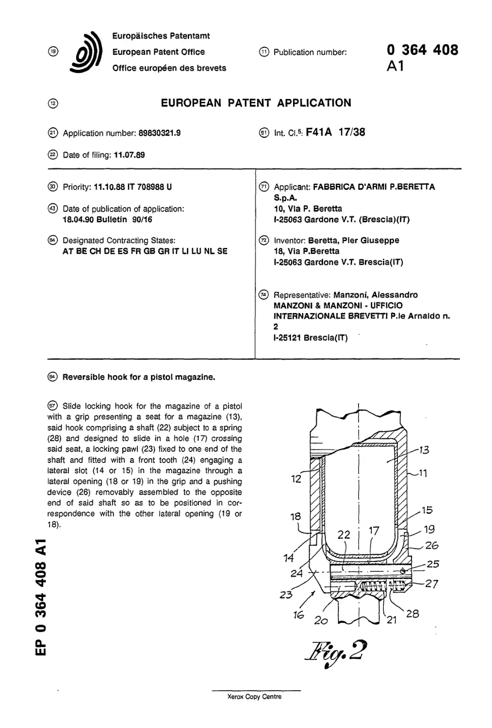
@ Slide locking hook for the magazine of a pistol
with a grip presenting a seat for a magazine (13),
said hook comprising a shaft (22) subject to a spring
(28) and designed to slide in a hole (17) crossing
said seat, a locking pawl (23) fixed to one end of the
shaft and fitted with a front tooth (24) engaging a
lateral slot (14 or 15) in the magazine through a
lateral opening (18 or 19) in the grip and a pushing
device (26) removably assembled to the opposite
end of said shaft so as to be positioned in cor-
respondence with the other lateral opening (19 or
18).
ЕР 0 364 408 А1
Xerox Copy Centre
1
ЕР 0 364 408 А1
2
REVERSIBLE HOOK
This utility model relates to a sliding hook to
lock and unlock pistol magazines and in particular
to a reversible hook for said purpose.
In the field of pistols different kinds of hooks
designed for the locking and unlocking of the mag-
azine placed in the pistol grip are already known. In
fact, a sliding lock hook is known, which is placed
and transversally guided with respect to the seat of
the magazine and fitted with a tooth designed to
interact with a slot on one side of the magazine.
This type of hook is however unidirectional and
non-reversible as it can be assembled and op-
erated in one direction only.
In addition, patent N. 1,090,108 filed by the
same applicant discloses a sliding hook for maga-
zines to be used either as right hand hook or as
left hand hook and which is thus suitable both for
righthanded and lefthanded shots. To change its
position said reversible hook is pressure mounted
and dismounted, but its structure is quite complex
and sophisticated.
The purpose of this invention is instead to
propose a reversible sliding hook to lock and un-
lock pistol magazines, which is simple, easy to
handle, to assemble and disassemble.
For this purpose, a reversible hook for pistol
magazines as specified in Claim 1 is proposed.
The structural details of the proposed hook will be
more apparent from the description given
hereinafter with reference to the accompanying
drawing in which:
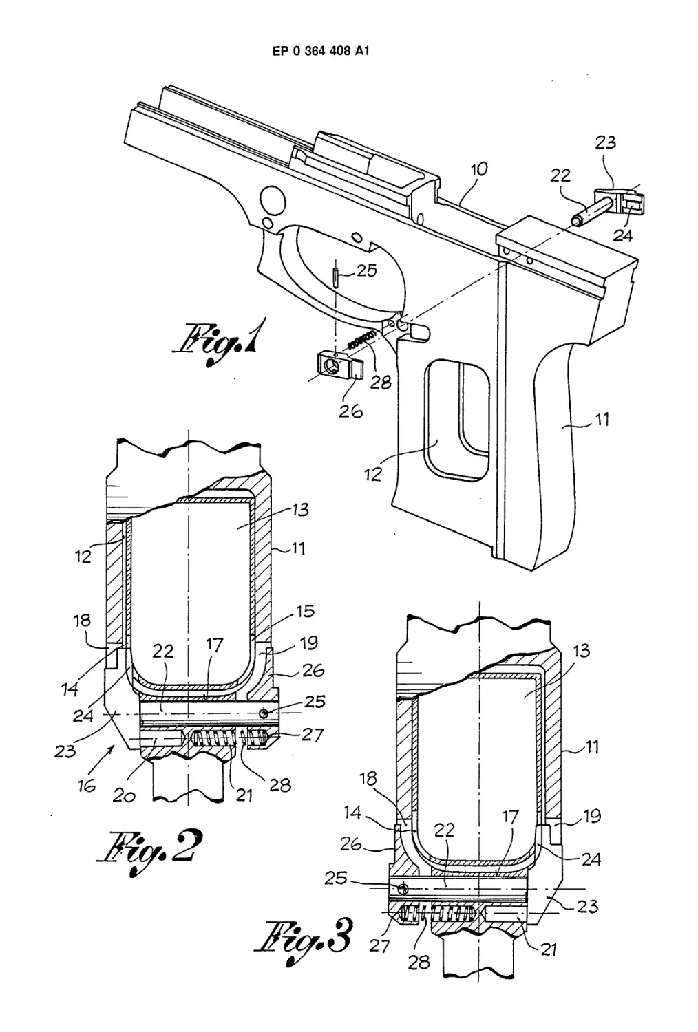
Figure 1 is a schematic and perspective
view of a pistol with exploded hook: and
Figures 2 and 3 show a partial horizontal
section of a pistol with righthand and lefthand hook
respectively.
In said drawing a pistol with shaft (10) and grip
(11) is shown, with a magazine (13) lodged in a
seat (12) inside said grip. The magazine (13) is
fitted, in a known manner, with two slots (14), (15),
one on each side, either one or the other of said
slots engaging the proposed locking hook (16).
In particular, inside grip (11) we have: a
through hole (17) transversal to seat (12) of maga-
zine (13), two lateral openings (18, 19) flush with
the ends of said through hole (17) and crossing
said seat (12); and two coaxial blind holes (20, 21)
parallel to through hole (17) and open on the op-
posite sides of grip (11).
Hook (16) is composed of a shank (22) fitted
with a pawl (23) bearing a tooth (24) at one end,
while on its opposite end a pushing device (26) is
fixed by means of a removable pin (25). The shape
of both said pawl (23) and pushing device (26) is
corresponding to lateral openings (18, 19)in pistol
FOR
5
10
15
20
25
30
35
40
45
50
A PISTOL MAGAZINE
grip (11) and in the inner face of the pushing
device (26) a recess (27) is made available for a
prestressed spring (28) mounted inside a blind hole
(20)or (21) in the grip.
As a matter of fact, to assemble the locking
hook (16) its shaft (22) is introduced into the
through hole (17) in grip (11) in such a way that its
pawl (23), (24) is protruding either into slot (14) or
into slot (15) in magazine (13) depending on the
position, right or left hand, required. After that, the
pushing device (26) is fixed to the free end of shaft
(22) by means of pin (25) after having fitted spring
(28) between device (26) and the opposite blind
hole (20) or (21). Now the locking hook (16) is
ready for use to lock and unlock the magazine, with
pawl (23) and its front tooth (24) fitted either to its
left hand side or to its right hand side, as shown in
Figures 2 and 3 respectively. In both cases spring
(28) will take and maintain the hook in locking
position: to release the hook and hence the maga-
zine in order to remove it from the grip, it is
necessary to push in the device (26) in opposition
to spring (28).
It is evident that the hook (16) may be dis-
mounted any time to be reassembled in its op-
posite position as will be required by the user of
the pistol. To do so it is enough to take off pin(25),
remove the pushing device (26) and then extract
the shaft (22)with pawl (23) from one side of the
grip to reinsert it in the opposite side, after fitting
spring (28) into its seat, and fix pushing device (26)
on the opposite end of shaft (22) by means of pin
(25).
Claims
1) Sliding hook to lock the magazine of pistols
with a grip comprising a seat for a magazine (13), a
through hole (17) transversally directed to said seat
and two lateral openings (18, 19) flush with the
ends of said through hole and crossing said seat
on correspondence with two slots (14, 15) on the
opposite sides of said magazine, characterized by
a shaft (22) to be introduced and slide in through
hole (17), a pawl (23) fixed to one end of said shaft
being fitted with a frontal tooth (24) engaging either
one or the other lateral slot (14 or 15) of the
magazine through the corresponding opening (18
or 19), by a pushing device (26) removably fitted to
the opposite end of said shaft so as to project from
the opposite opening (19 or 18), and by a spring
(28) to keep the pawl with locking tooth (23,24) in
the position required to lock in the magazine, the
magazine being released by acting on pushing
2
3
ЕР 0 364 408 А1
4
device (26) in opposition to spring (28).
2. Locking hook as claimed in claim 1, in which
said pushing device (26) is fitted to shaft (22) by
means of a removable pin (25).
3. Locking hook as claimed in claims 1 and 2,
in which spring (28) is placed between the pushing
device (26) and in one of the two opposite blind
holes (20,21) made available on the opposite sides
of the grip and parallel to through hole (17).
4. Locking hook as claimed in the preceding
claims, in which after detaching the pushing device
from shaft (22), said shaft with locking pawl (23, 24)
can be fitted into its opposite seat thus obtaining
the easy reversibility of the locking hook itself.
5
10
15
20
25
30
35
40
45
50
55
3
ЕР 0 364 408 А1
oZ
EUROPEAN SEARCH REPORT
Application Number
EP 89 83 0321
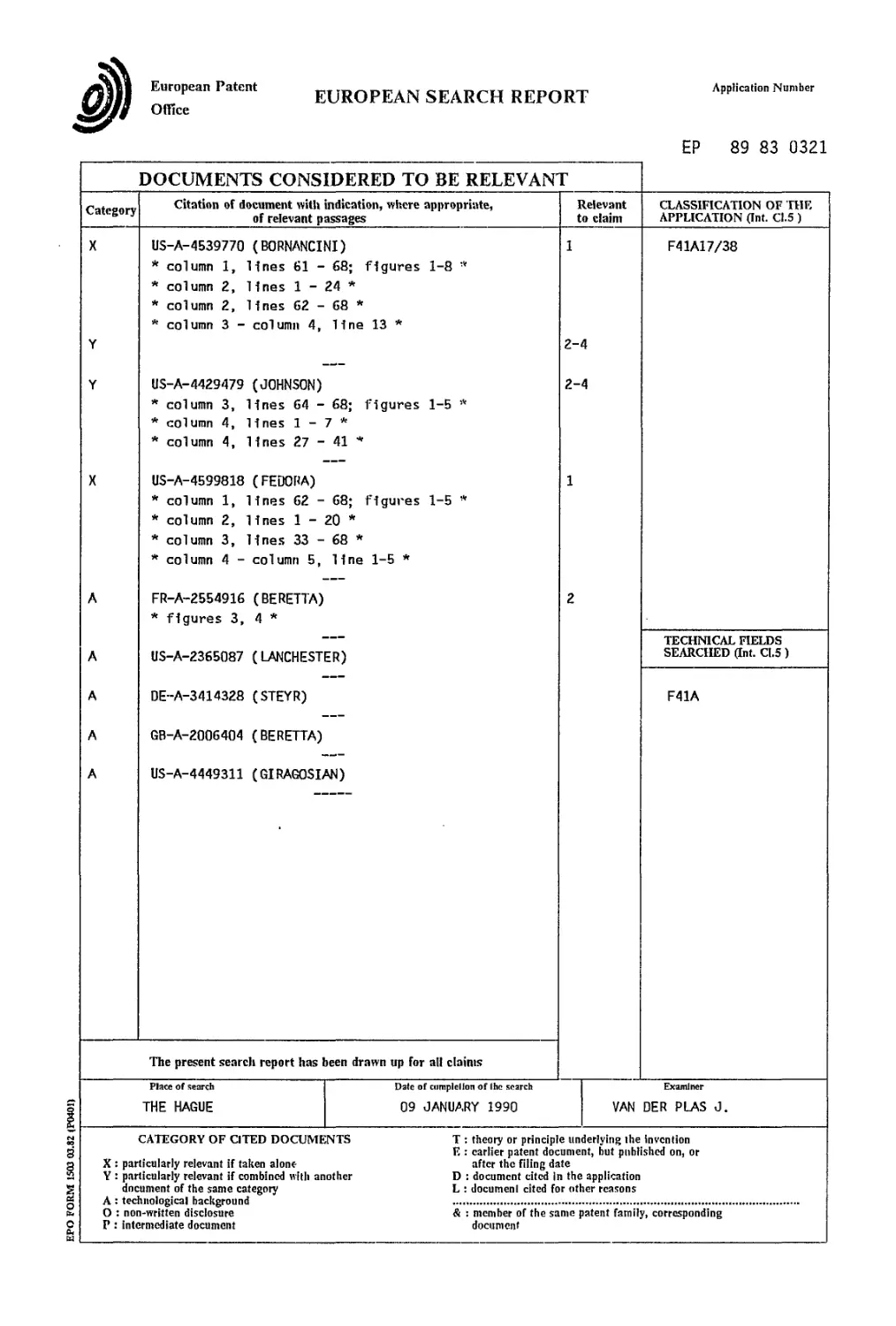
DOCUMENTS CONSIDERED TO BE RELEVANT
EPO FORM 1503 03.82 (Р0401)
Category Citation of document with indication, where appropriate, of relevant passages Relevant to claim CLASSIFICATION OF HIE APPLICATION (Int. C1.5 )
X Y Y X A A A A A US-A-4539770 (BORNANCINI) * column 1, lines 61 - 68; figures 1-8 * * column 2, lines 1 - 24 * * column 2, lines 62 - 68 * * column 3 - column 4, line 13 * US-A-4429479 (JOHNSON) * column 3, lines 64 - 68; figures 1-5 * * column 4, lines 1 - 7 * * column 4, lines 27 - 41 * US-A-4599818 (FEDORA) * column 1, lines 62 - 68; figures 1-5 * * column 2, lines 1 - 20 * * column 3, lines 33 - 68 * * column 4 - column 5, line 1-5 * FR-A-2554916 (BERETTA) * figures 3, 4 * US-A-2365087 (LANCHESTER) DE-A-3414328 (STEYR) GB-A-2006404 (BERETTA) US-A-4449311 (GIRAGOSIAN) 1 2-4 2-4 1 2 F41A17/38
TECHNICAL FIELDS SEARCHED ant. Cl.5)
F41A
The present search report has been drawn up for all claims
Place of search THE HAGUE Date of completion of the search 09 JANUARY 1990 Examiner VAN DER PLAS J.
CATEGORY OF CITED DOCUMENTS T : theory or principle underlying the invention E : earlier patent document, but published on, or X : particularly relevant if taken alone after the filing date Y : particularly relevant if combined with another D : document cited in the application document of the same category L : documenl cited for other reasons A : technological background О : non-written disclosure & : member of the same patent family, corresponding P : intermediate document document