/
Tags: weapons military affairs patent
Year: 1987
Text
Europaisches Patentamt
(Я) European Patent Office
Office europeen des brevets
® Publication number:
0 239 544
B1
©
EUROPEAN PATENT SPECIFICATION
(45) Date of publication of patent specification: 07.11.90
@ Application number: 87830018.5
© Date of filing: 20.01.87
© Int el.5: F 41 A 17/66
(54) Pistol with automatic safety device on firing pin.
© Priority: 21.03.86 IT514686
© Date of publication of application:
30.09.87 Bulletin 87/40
@ Proprietor: FABBRICA D'ARMI P.BERETTA
S.p.A.
10, Via P. Beretta
1-25063 Gardone V.T. (Brescia) (IT)
© Publication of the grant of the patent:
07.11.90 Bulletin 90/45
@ Inventor: Beretta, Pier Giuseppe
18, Via P. Beretta
1-25063 Gardone V.T. (Brescia) (IT)
© Designated Contracting States:
AT BE CH DE ES FR GB GR LI
ЕР О 239 544 В1
@ References cited:
DE-C- 670 241
FR-A-2 104 121
FR-A-2 176 061
FR-A-2 418 437
FR-A-2 461 917
GB-A- 660 046
US-A-3 996 686
© Representative: Manzoni, Alessandro
MANZONI & MANZONI - UFFICIO
INTERNAZIONALE BREVETTI P.le Arnaldo n. 2
1-25121 Brescia (IT)
Note: Within nine months from the publication of the mention of the grant of the European patent, any person may
give notice to the European Patent Office of opposition to the European patent granted. Notice of opposition shall
be filed in a written reasoned statement. It shall not be deemed to have been filed until the opposition fee has been
paid. (Art. 99(1) European patent convention).
Courier Press, Leamington Spa, England.
239
5
10
15
20
25
30
35
40
45
50
55
60
65
1 ЕР О
Description
The present invention relates in general to
automatic pistols having automatic safety on their
firing pin, and in particular to a new and useful
device for the automatic return to rest or to an
inoperative position of the striking mechanism for
the hammer of such a pistol.
In the field of safety devices for automatic
pistols, automatic safety devices are known for
the firing pin of the weapon. These safety devices
are capable of preventing the operation of the pin
and thus the firing of a bullet from the barrel of
the weapon, as a result of an accidental dropping
of the weapon and/or of an involuntary and
uncontrolled action of the hammer on the firing
pin itself. Such a device comprises a safety block
mounted on the breech block of the firing pin of
the pistol (hereinafter called the carriage) in a
plane perpendicular to the axis of the firing pin
and in an intercepting and blocking position of the
firing pin, when the trigger is at rest. The safety
block is normally in a working position for block-
ing the firing pin and is displaced to the rest or
inoperative position forfreeing the firing pin, only
at the moment when the hammer is disengaged
by the trigger.
Safety devices on the firing pin of the kind have
been disclosed, for instance, in GB—A—660 046,
FR—A—2 104 121 and FR—A—2 176 061.
Another safety device has been described in
US—A—3 996 686, but it is designed for an arm
where the cock is to be taken out of or in
alignment with the firing pin.
Another known safety device, as disclosed by
FR—A—2 418 437 issued to the present applicant
(and corresponding to US—A—4 306 487), con-
cerns automatic pistol of the type having a so-
called "interrupted firing pin". Such a pistol has a
body, a carriage movable on said body, a firing
pin mounted for movement to said carriage, said
firing pin having a first portion movable in a
selected direction and a second portion alignable
with said first portion for being movable there-
with in said selected position and disalignable
with said first portion, a hammer mounted for
movement from a cocked position away from said
second portion to a firing position toward said
second portion for moving said second portion in
its aligned position in said selected direction, said
hammer having associated a trip lever for causing
said hammer to move from its cocked position to
its firing position, a manually rotatable cammed
shaft rotatably mounted to said carriage on an
axis which is transverse to said selected direction,
said second portion being mounted on said cam-
med shaft for movement from its aligned position
to its disaligned position with rotation of said
shaft, said cammed shaft having a cam portion, a
movably mounted rocking lever movable for
engaging said trip lever to move said hammer
from its cocked position to its firing position when
said cam portion of said cammed shaft engages
said rocking lever and as said cammed shaft
rotates to move said second portion of said firing
544 B1 2
pin from its aligned position to its disaligned
position.
This device comprises however a safety shaft
which is manually operative and interacting with
the firing pin so as to neutralize the action thereof.
The safety shaft also interacts through the action
of an intermediate lever, with a trip lever of the
hammer, so as to automatically disengage the
hammer immediately following the neutralization
of the firing pin. The firing pin is formed by two
elements, a spring-actuated frontal one and a rear
one that is mounted on the safety shaft and which
is positionable by their axially or non-axially with
respect to the frontal element mentioned above,
in order to activate and, respectively neutralize
the firing pin.
According to this known art and technique, the
safety shaft is rotated on the carriage and is
mounted in a direction which is transverse to the
firing pin. Further, it is provided with a cammed
portion which controls the intermediate lever that
is interacting with the tripped lever for the auto-
matic disengagement of the hammer, when the
shaft or rod is rotated to neutralize the action of
the interrupted firing pin.
In practice, the safety shaft must be displaced
manually, and therefore, voluntarily, by means of
a control lever both in the working position and in
the rest position, which positions are determined
and defined by at least one spring-loaded locking
means. According to the above described
arrangement, the safety shaft rod, when in the
safety working position, may control a small
spring loaded piston that interacts with a trigger
rod connected to the trigger which actuates the
trip lever of the hammer.
The tripping mechanism is then moved away
from the trip lever, so as to avoid the possibility
that the user might act on the tripping mechanism
when the weapon is in the safety position.
A pistol may now be provided, concurrently,
with the automatic safety blocking mechanism on
the firing pin (e.g. GB—A—660 046) and with an
automatic disengaging device for the hammer
when the weapon is in its safety position (e.g.
FR—2 418 437). Under these circumstances, since
the automatic safety blocking device on the firing
pin is always operative until the trigger is acted
upon, it is no longer necessary to also have a
manually operated safety device or some means
for moving the trigger rod away from the trip
lever.
There remains, nevertheless, the need for
means for the disengagement and the striking of
the hammer, when the weapon is not to be used.
These means for the disengagement of the
hammer should, however, return automatically,
after each action thereof, to a rest position corre-
sponding to the position of readiness to fire the
weapon. This is necessary in order not to impede
or delay immediate reuse of the pistol without
any manual intervention.
Starting from the above described premise, it is
an object of the present invention to provide a
device which is applicable to automatic pistols of
2
3
ЕР 0 239 544 В1
4
the type having automatic safety means on the
firing pin and a leverforthe manual striking of the
hammer, which device allows the automatic
return to a rest or inoperative position of the
striking means of the hammer, so as to leave the
weapon always in a position of readiness to fire
and immediate reuse.
It is another object of the present invention to
provide a device for the automatic return to a rest
or inoperative position of the striking means of
the hammer, which device employs and exploits
the very same safety element disclosed in
FR—A—2 418 437, although structurally differ-
ently arranged.
It is possible, therefore, to obtain the advantage
of having a device mounted on the carriage and
free of the danger of being inadvertently actuated
and of uncontrollably disengaging the cocked
hammer, in the event of a rapid operation of the
carriage itself during the arming of the pistol.
For this purpose, the present invention is
directed to an automatic pistol provided with a so-
called interrupted type firing pin in accordance
with the preamble of claim 1 which corresponds
to FR—A—2 418 437 and is characterised in that it
includes a safety block (as disclosed by
GB—A—660 046) provided on said carriage for
blocking axial movement of said first firing pin
portion in said selected direction, and is also
characterized in that a spring loaded pusher is
mounted for movement to said carriage, and
further in that said cammed shaft has at least one
eccentric surface located eccentrically of said axis
of cammed shaft and engaged by said spring
loaded pusher for rotating said cammed shaft in a
direction to move said second portion of said
firing pin from its disaligned position to its
aligned position.
Also, on said carriage a cammed cavity is
provided and a spring loaded auxiliary piston is
mounted for movement to said cammed shaft
and engageable in said cammed cavity for hold-
ing paid cammed shaft in a position whereat said
second portion of said firing pin is in aligned
position.
For a better understanding of the invention, its
operating advantages and specific objects
attained by its uses, reference is made to the
accompanying drawings and descriptive matter
in which a preferred embodiment of the invention
is illustrated.
In the drawings:
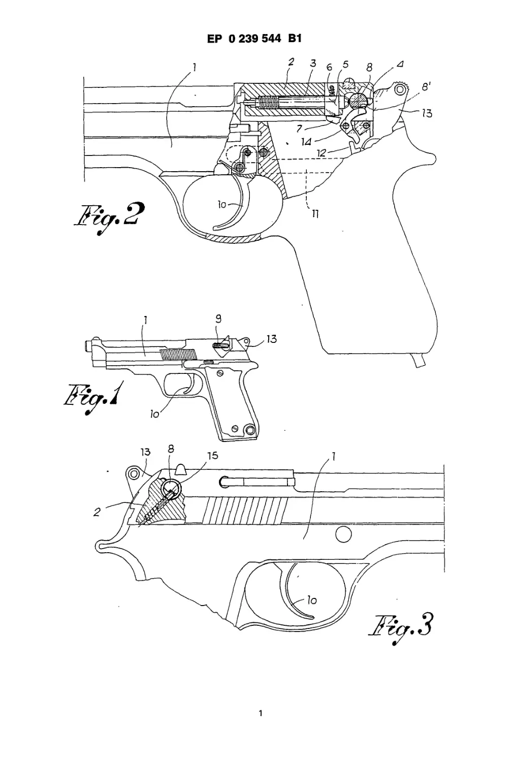
Fig. 1 is a side elevational view of an automatic
pistol including the device of the present inven-
tion;
Fig. 2 is a partial, longitudinal sectional view of
the pistol taken in the plane of the firing pin and
partly in elevation;
Fig. 3 is a partial sectional, side view of the
pistol, opposite to the view of Fig. 2;
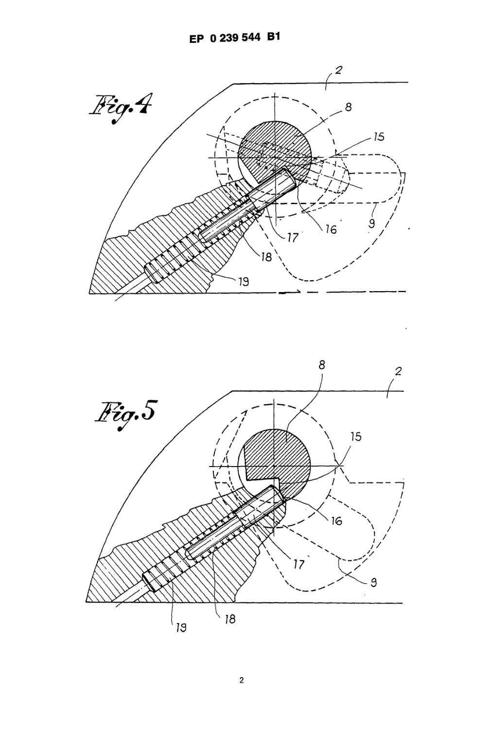
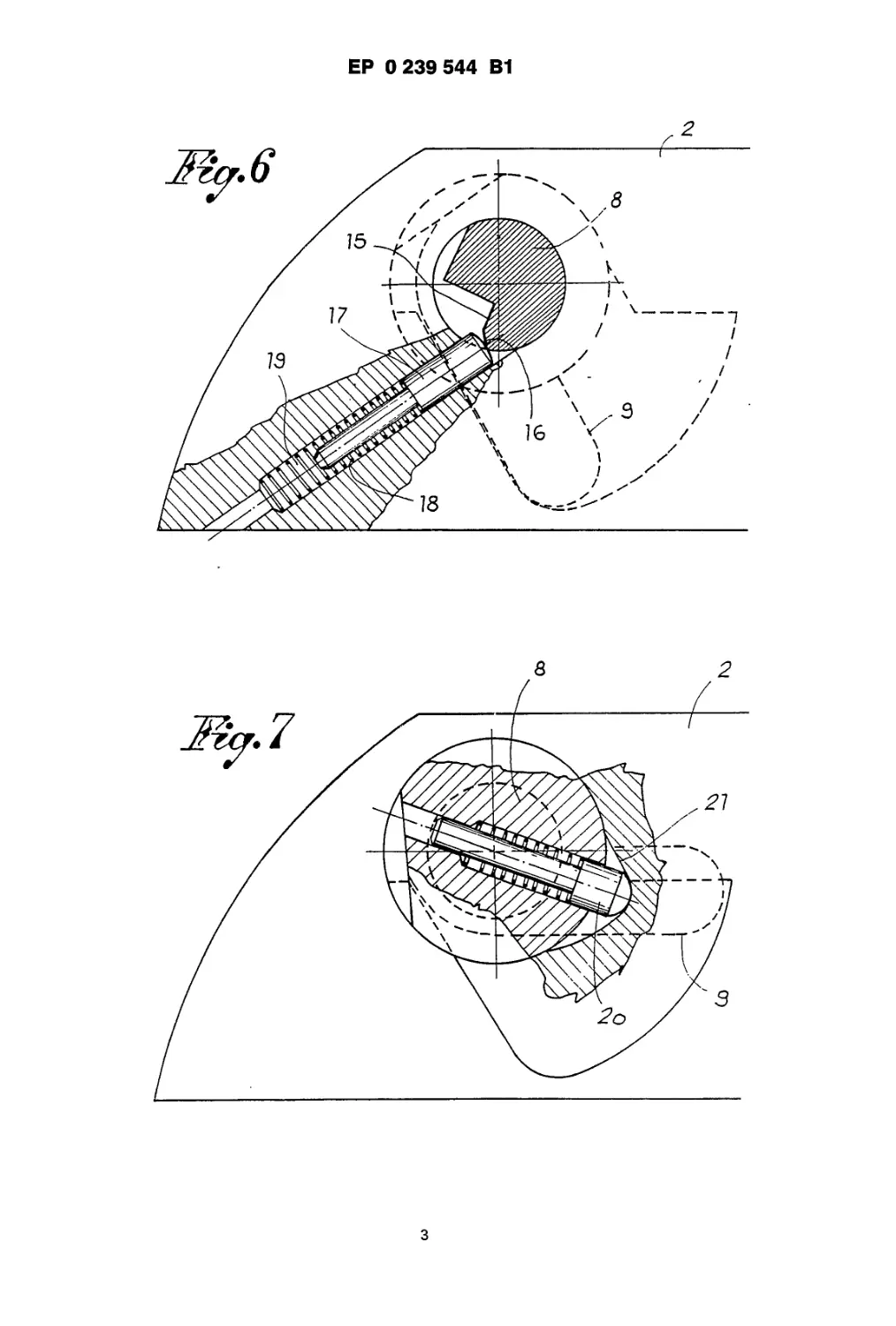
Figs. 4, 5 and 6 are sectional views showing
three consecutive positions of the rotating shaft
or rod which controls the disengagement of the
hammer; and
Fig. 7 is a sectional view of the auxiliary means
5
10
15
20
25
30
35
40
45
50
55
60
65
for the blockage of the shaft or rod in a rest or
inoperative position.
Referring now to Figs. 1 through 3, a carriage 2
for the firing pin is mounted in a known manner to
the body 1 of the pistol. The firing pin is of the so-
called "interrupted" type and comprises a spring-
loaded, frontal element 3 and a rear element 4
that can be positioned either axially or non-axially
with respect to the frontal element for the actua-
tion and, respectively, neutralization of the firing
pin.
The frontal element is associated with an auto-
matic safety block 5 mounted on the carriage 2 in
a direction perpendicular to the axis of firing pin
and movable from a first position, in which it
intercepts and blocks the firing pin, to a second
position, in which it is at rest, so as to allow the
firing pin to be operative. The safety block 5 is
normally kept in the working position by a spring
6, which acts in a downward direction and is
moved upwardly to a rest position by a rocking
lever 7.
The rear element 4 of the firing pin, on the other
hand, is mounted on a rotating shaft or .rod 8
positioned transversely on the carriage 2 and
provided, at one extremity thereof, with a control
lever 9.
The pistol further comprises a trigger 10, to
which is connected one extremity of a tripping
mechanism 11. The opposite extremity of the
tripping mechanism 11 cooperates, in a manner
known per se, with a trip lever 12 (for the
engagement and disengagement of the hammer
13) with the hammer itself and with the rocking
lever 7 (for the displacement of the safety block 5
of the firing pin to a rest position, when the trigger
is acted upon). The rotating shaft 8 is provided
with a cammed portion defined by a levelling or
abatement 8' and cooperates, in a manner
already known, with a rocking lever 14, which in
turn serve to displace the trip lever 12, so that the
hammer 13 might be disengaged each time the
shaft is rotated by the manual operation of the
control lever 9.
In orderto disengage the hammer 13, when the
weapon is not to be used, it is sufficient to rotate
the shaft 8, obtaining at the same time a displace-
ment of the rear element 4 of the firing pin, axially
disaligned with respect to the frontal element 3.
The firing pin will concurrently be neutralized,
even if temporarily.
The shaft 8 is in fact so arranged so as to
automatically return to its original rest of inopera-
tive position as soon as the manual action on it
(which caused its original displacement) ceases.
This will result in the realignment of the rear
element 4 of the firing pin with the frontal element
3, so that the weapon is now ready for its
successive employment without further manual
intervention.
To this effect, the shaft 8 is provided on its
extremity opposite to that which is connected to
the control lever, with a step 15 eccentrically
made with respect to the axis of the shaft. The
shaft is, further, provided with a rdial plane or
3
5
ЕР 0 239 544 В1
6
surface 16, which connects with the step 15 on the
outer surface of the shaft. Step 15 is associated
with a piston-line pusher 17 urged by a pre-
compressed spring 18. Both pusher 17 and spring
18 are seated or positioned in a seat 19 provided
in the sides of the carriage 2 and are oriented in a
tangential direction with respect to the shaft 8.
The action of the spring-actuated piston 17, 18
against the eccentric step 15 of the shaft 8 creates
a torque force moment which tends to keep the
shaft in the rest or inoperative position (see Fig. 4)
and to return it automatically to this position after
each rotation thereof (see Fig. 6). In fact, when the
safety is rotated to the working position for the
disengagement of the hammer, the spring 18 is
loaded further, thus increasing the torque which
permits the return of the shaft to its original
position. On the other hand, when the shaft is
fully rotated in the working position (see Fig. 6),
the spring loaded piston 17,18 is in position to act
against the radial plane or surface 16, positioned
at its maximum distance from the axis of the
shaft, so that the torque moment is greatest and
favors even more the rotation of the shaft in the
opposite direction.
It is to be observed, finally, that the shaft 8 may
be provided, adjacent the control lever 9 with a
spring-loaded auxiliary piston 20, which rotates
together with the shaft 8 and which cooperates
with a cammed hollow or cavity 21 constructed in
carriage 2 for defining and establishing the rest or
inoperative position of the shaft, as shown par-
ticularly in Fig. 7 of the drawings.
Claims
1. A piston having a body (1), a carriage (2)
movable on said body, a firing pin (3—4) mounted
for movement to said carriage (2), said firing pin
having a first portion (3) movable in a selected
direction and a second portion (4) alignable with
said first portion for being movable therewith in
said selected position and disalignable with said
first portion, a hammer (13) mounted for move-
ment from a cocked position away from said
second portion (4) to a firing position toward said
second portion (4) for moving said second portion
in its aligned position in said selected direction,
said hammer (13) having a trip lever (12) for
causing said hammer to move from its cocked
position to its firing position, a manually rotatable
cammed shaft (8—8') rotatably mounted to said
carriage (2) on an axis which is transverse to said
selected direction, said second portion (4) being
mounted on said cammed shaft (8—8') for move-
ment from its aligned position to its disaligned
position with rotation of said shaft, said cammed
shaft having a cam portion, a movably mounted
rocking lever (14) movable for engaging said trip
lever (12) to move said hammer from its cocked
position to its firing position when said cam
portion of said cammed shaft engages said rock-
ing lever and as said cammed shaft rotates to
move said second portion of said firing pin from
its aligned position to its disaligned position.
5
10
15
20
25
30
35
40
45
50
55
60
65
characterised in that said pistol includes a safety
block (5) movably to said carriage for blocking
movement of said first portion (3) of said firing
pin in said selected direction, and in that a spring
loaded pusher (17) is mounted for movement to
said carriage (2), and further in that said cammed
shaft (8—8') has at least one eccentric surface (15)
located eccentrically of said axis of cammed shaft
and engaged by said spring loaded pusher (17)
for rotating said cammed shaft in a direction
automatically to move said second portion (4) of
said firing pin from its disaligned position to its
aligned position.
2. The improvement of claim 1, wherein said
eccentric surface comprises a step (15) formed in
said cammed shaft (18) at an eccentric location
with respect to said axis of said cammed shaft,
said spring loaded pusher (17) being engageable
with said step (15) for rotating said cammed shaft
to move said second portion of said firing pin
from said disaligned position to said aligned
position.
3. The improvement of claim 2, wherein said
carriage (2) includes a seat (19), said spring
loaded pusher being mounted for movement in
said seat and including a piston (17) movable in
said seat and a spring (18) in said seat biasing
said piston toward said cammed shaft (8—8').
4. The improvement of claim 3, wherein said
eccentric surface of said cammed shaft includes a
radial portion (16) adjacent said step (15) and
more eccentric than said step with respect to said
axis, said cammed shaft being rotatable manually
to an extreme position for moving said second
portion (4) of said firing pin to its disaligned
position, said piston (17) being engaged with said
radial surface in said extreme position of said
cammed shaft for rotating said cammed shaft
away from its extreme position.
5. The improvement of claim 4, wherein said
carriage (2) includes a cammed cavity (21), and a
spring loaded auxiliary piston (20) mounted for
movement to said cammed shaft (8) and
engageable in said cammed cavity (21) for hold-
ing said cammed shaft in a position whereat said
second portion of said firing pin is in aligned
position.
Patentanspriiche
1. Pistole mit einem Gehause (1), einem auf
dem Gehause verschiebbaren Wagen (2), einem
dem Wagen (2) gegenuber beweglichen Zundstift
(3—4), dessen erster Teil (3) in einer bestimmten
Richtung beweglich ist, wahrend sein zweiter Teil
(4) dem ersten Teil (3) so zugeordnet ist, daB er
mit ihm gemeinsam in die gewahlte Position
geschoben bzw. von ihm abgesetzt werden kann,
einem Hahn (13) der von einer gespannten Stel-
lung im Abstand vom zweiten Teil (4) in eine
SchieBstellung auf den zweiten Teil (4) hin
bewegt wird um den zweiten Teil auszurichten,
wobei der Hahn (13) einen Schalthebel (12) auf-
weist, der ihn von der gespannten in die SchielS-
stellung bewegt, eine von Hand drehbare Nocken-
4
7
ЕР 0 239 544 В1
8
welle (8—8'), die schwenkbar an das Gehause (2)
und quer zu der oben bestimmten Richtung ein-
gesetzt ist, wobei der zweite Teil (4) derart an die
Nockenwelle (8—8') angebracht ist, dalS er durch
Drehung der Nockenwelle von seiner ausgerichte-
ten in seine nicht ausgerichtete Position
geschwenkt wird, wobei die Nockenwelle einen
Nockenteil und einen Schwinghebel (14) aufweist,
der in Zusammenwirkung mit dem Schalthebel
(12) den Hahn (13) von seiner gespannten in seine
SchieiSstellung bewegt sobaid der Nockenteil der
Nockenwelle in den Schalthebel (12) eingreift und
die Nockenwelle sich dreht um den zweiten Teil
des Zundstifts von seiner ausgerichteten in seine
nicht ausgerichtete Stellung zu uberfuhren,
dadurch gekennzeichnet, dalS an dem Gehause
der Pistole eine darauf verstellbare Sicherung (5)
angebracht ist, um die Bewegung des ersten Teils
(3) des Zundstifts in die gewahlte Richtung zu
stoppen und dalS ein federbelasteter Schieber (17)
die Annaherung zum Wagen (2) bewirkt, dalS die
Nockenwelle (8—8') mindestens eine ihrer Achse
gegeniiber versetzte Exzenterflache (15) aufweist,
die beim Eingreifen des federbelasteten Schie-
bers (17) eine Drehung der Nockenwenwelle
bewirkt, durch die der zweite Teil (4) des Ziindstif-
tes automatisch aus seiner nicht ausgerichteten in
seine ausgerichtete Stellung bewegt wird.
2. Pistole nach Anspruch 1, dadurch gekenn-
zeichnet, daB die Exzenterflache der Nockenwelle
(8—8') eine zur Achse der Nockenwelle versetzte
Stufe (15) aufweist, in die der federbelastete
Schieber (17) eingreifen kann, um eine Drehung
der Nockenwelle zu bewirken, durch die der
zweite Teil des Zundstifts von seiner nicht ausge-
richteten in seine ausgerichtete Stellung bewegt
wird.
3. Pistole nach Anspruch 2, dadurch gekenn-
zeichnet, dalS der Wagen (2) mit einer Aufnahme
(19) versehen ist, in der sich der federbelastete
Schieber mit einem Kolben (17) bewegt und eine
Feder (18) den Kolben auf die Nockenwelle (8—8')
verspan nt.
4. Pistole nach Anspruch 3, dadurch gekenn-
zeichnet, dalS die Exzenterflache der Nockenwelle
eine an die Stufe (15) anschlielSende radiale Teil-
flache (16) aufweist, die weiter als die Stufe (15)
zur Achse der Nockenwelle versetzt ist, wobei die
Nockenwelle von Hand in eine Endstellung dreh-
bar ist, um den zweiten Teil (4) des Zundstiftes in
seine nicht ausgerichtete Stellung zu bringen, bei
gleichzeitigem Eingriff des Kolbens (17) in die
genannte radiale Teilflache der Nockenwelle, um
dieselbe aus ihrer Endstellung zu bewegen.
5. Pistole nach Anspruch 4, in der der Wagen (2)
eine Nockenausnehmung (21) und einen federbe-
lasteten, die Nockenwelle (8) bewegenden Hilfs-
kolben (20) aufweist, der in Zusammenwirkung
mit der Ausnehmung (21) die Nockenwelle arre-
tiert wenn der zweite Teil des Zundstifts sich in
seiner ausgerichteten Stellung befindet.
Revendications
1. Un pistolet ayant un corps (1), un chariot (2)
5
w
15
20
25
30
35
40
45
50
55
60
65
mouvant sur le corps (1), un percuteur (3—4)
monte pour se mouvoir par rapport au chariot (2),
le percuteur comprenant une premiere partie (3)
mouvant dans une direction selectionnee et une
deuxieeme partie (4) alignable avec la premiere
partie pour se mouvoir avec elle dans la direction
selectionnee et desalignable avec la premiere
partie, un chien (13) monte pour se deplacer
d'une position armee eloignee de la deuxieme
partie (4) vers une position de decharge pres de la
deuxieeme partie (4) pour deplacer cette
deuxieme partie en position alignee dans la direc-
tion selectionee, le chien (13) etant muni d'un
levier de declenchement (12) pour le mouvoir de
sa position armee vers sa position de decharge,
un arbre a cames (8—8') a rotation manuelle
pivotant sur le chariot (2) autour d'un axe trans-
versal a la direction selectionnee susdite, la
deuxieme partie (4) etant montee sur I'axe a
cames (8—8') pour son mouvement des sa posi-
tion alignee vers sa position desalignee par la
rotation de I'axe susdit, cet axe a cames ayant une
partie a cames, un levier oscillant (14) pour
engager le levier de declenchement (12) pour
deplacer le chien (13) de sa position armee en
position de decharge quand la partie a cames de
I'arbre a cames engage le levier oscillant et tant
que I'arbre a cames tourne pour mouvoir la
deuxieme partie du percuteur des sa position
alignee ver sa position desalignee, caracterise en
ce que le pistolet comprend un bloc de surete (5)
mouvant sur le chariot (2) pour arreter le mouve-
ment de la premiere partie (3) de percuteur vers le
direction selectionnee et en ce qu'un poussoir a
ressort (17) est monte pour son mouvement vers
le chariot (2) et en plus en ce que I'arbre a cames
(8—8') a au moins use surface excentrique (15)
dans une position excentrique par rapporta I'axe
de I'arbre a cames et engagee par le poussoir a
ressort (17) pourtourner I'arbre a cames dans une
direction qui deplace automatiquement la
deuxieme partie (4) du percuteur de sa position
alignee vers sa position desalignee.
2. Pistolet selon la revendication 1, dans lequel
la surface a cames comprend un gradin (15)
forme sur I'arbre (8) dans une position excentri-
que par rapport a I'axe de I'arbre a cames, le
poussoir a ressort (17) pouvant s'engager avec le
gradin (15) pour tourner I'arbre a cames de
maniere a mouvoir la deuxieme portion du percu-
teur des sa position desalignee vers sa position
alignee.
3. Pistolet selon la revendication 2, dans lequel
le chariot (2) comprend un siege (19), le poussoir
a ressort (17) se mouvant dans ce siege et
comprenant un piston (17) mouvant dans ce siege
et un ressort (18) dans ce siege qui tend le piston
vers I'arbre a cames (8—8').
4. Pistolet selon la revendication 3, dans lequel
la surface excentrique de I'arbre a cames com-
prend une partie radiale (16) pres du gradin (15) et
plus excentrique du gradin par rapport 3 I'axe
susdit, I'arbre a cames etant tournable a main
dans une position extreme de maniere a porter la
deuxieme partie (4) du percuteur dans une posi-
5
9
ЕР 0 239 544 В1
ю
tion desalignee, le piston (17) etant engage avec
la surface radiale dans la position extreme de
I'arbre a cames pour tourner I'arbre a cames et
I'eloigner de sa position extreme.
5. Pistolet selon la revendication 4, dans lequel
le chariot (2) comprend une cavite a cames (21) et
5
10
15
20
25
30
35
40
45
50
55
60
65
un piston auxiliaire a ressort (20) monte pour
mouvoir vers I'arbre a cames (18) et a engager
dans la cavite a cames (21) pour maintenir I'arbre
a cames dans une position ou la deuxieme partie
du percuteur se trouve en position alignee.
6
ЕР 0 239 544 В1
1
ЕР 0 239 544 В1
2
ЕР 0 239 544 В1
з