/
Tags: weapons military affairs patent
Year: 1989

Text
Europaisches Patentamt
European Patent Office
Office europeen des brevets
12
0 Publication number:
0 343 115 Bl
EUROPEAN PATENT SPECIFICATION
0 Date of publication of patent specification: 08.06.94 0 int. CIA F41A 17/00
0 Application number: 89830012.4
0 Date of filing: 13.01.89
0 Safety means for the bolt of automatic and semiautomatic pistols.
0 Priority: 20.05.88 IT 516588
0 Date of publication of application:
23.11.89 Bulletin 89/47
0 Publication of the grant of the patent:
08.06.94 Bulletin 94/23
0 Designated Contracting States:
AT BE CH DE ES FR GB GR IT LI LU NL SE
0 References cited:
FR-A- 533 077
US-A- 1 382 317
US-A- 1 557 435
US-A- 2 353 722
US-A- 3 657 959
0 Proprietor: FABBRICA D'ARMI P.BERETTA
S.p.A.
10, Via P. Beretta
I-25063 Gardone V.T. (Brescia)(IT)
0 Inventor: Beretta, Pier Giuseppe
18, Via P. Beretta
I-25063 Gardone V.T. (Brescia)(IT)
0 Representative: Manzoni, Alessandro
MANZONI & MANZONI,
UFFICIO INTERNAZIONALE BREVETTI,
P.le Arnaldo n. 2
1-25121 Brescia (IT)
ЕР 0 343 115 В1
Note: Within nine months from the publication of the mention of the grant of the European patent, any person
may give notice to the European Patent Office of opposition to the European patent granted. Notice of opposition
shall be filed in a written reasoned statement. It shall not be deemed to have been filed until the opposition fee
has been paid (Art. 99(1) European patent convention).
Rank Xerox (UK) Business Services
(3. 10/3.09/3.3.3)
1
ЕР 0 343 115 В1
2
Description
The present invention relates, in general, to
semiautomatic and automatic pistols and, more
particularly, to a safety means for arresting the bolt
of these pistols in case of an emergency.
Semiautomatic, as well as automatic pistols
comprise usually a bolt which is guidedly capable
of operational, longitudinal movements or displace-
ments, back and forth along and on the body of the
firearm.
FR-A-533 077 discloses a pistol in which the
retromovement of the breech bolt is limited through
an arresting means situated at the rear end of the
body. In such a pistol, said body has lateral guide
ribs on which runs the bolt having two correspond-
ing grooves. The arresting means comprises a step
at the rear end of at least one of the guide ribs and
a step within the corresponding groove. The two
steps interact to lock the bolt in case of breakage.
US-A-1 557 435 also discloses a pistol in which
the retromovement of the bolt is limited through a
stop means situated at the rear end of the body. In
this case, the stop means comprises a pin moun-
ted on the pistol body and pushed towards the bolt
to interact with a step in the bolt.
In the both arrangements, the arresting means
are thus situated at the rear part of the pistol body
and are functional: no other safety devices are
envisaged for the bolt.
A pistol arrangement disclosed in US-A-1 382
317 has a stop means which is identical to the one
in US-A-1 557 435 above, but differs in that it is
designed to limit the forward movement of the bolt.
In practice and in the market there are also
pistols in which the breech bolt is fitted with a
arresting means situated at the front and interacting
with the fixed shoulder at the front of said body to
limit the retromovement of said bolt. The forward
movement of the bolt is limited on closure when it
comes into contact with the pistol body.
In fact, this known pistol arrangement com-
prises a pistol body including and upper bolt-en-
gaging portion with a fixed shoulder adjacent to the
front end of said pistol body, and a bolt including
an arresting portion adjacent to the front end of
said bolt, with said arresting portion engaging said
fixed shoulder upon retromovement of said bolt
along the pistol body by propelling gases of a
shell, for limiting the retromovement of said bolt
with respect to said pistol body, said arresting
portion being positioned spaced a distance from
said fixed shoulder in a pre-firing state, said dis-
tance from said arresting portion to said fixed
shoulder defining a retromovement distance.
Furthermore, the breech bolt of such a pistol
arrangement may, for structural and functional rea-
sons, have an intermediate part of reduced cross
5
10
15
20
25
30
35
40
45
50
55
section and resistance situated behind the arresting
portion.
Now, unexpected or accidental causes or rea-
sons, such as the incorrect use of the pistol, the
careless maintenance thereof, the employment of
improper ammunition or of cartridges with exces-
sive charge, etc. may be a source of cracks or
faulty lines, which as time goes on result in the
breaking of the bolt. The breakage may occur in
areas of lesser resistance, such as those in the
back of the arresting means which limit the retro
movement of the bolt. In such a case, the normal
arresting means provided on the bolt are insuffi-
cient to prevent that the rear portion there of no
longer held, be violently projected rearwardly when
the projectile that causes the final ultimate break-
age of the bolt is fired, with the attendant danger to
the user of the pistol. Hence, the need to provide
this type of pistols with means which can prevent
such an occurrence, in the event that the bolt be
broken, and keep the user from physical injury.
It is therefore, the main object of the present
invention to provide a safety means for pistols in
addition to the usual arresting means at it front
end, which safety means might block on the body
of the firearm, preventing its retro-movement, the
rear portion of the bolt and, thusly, avoid that the
eventually cracked and broken part of the bolt be
projected against the user.
Thus, the present invention is directed to a
pistol arrangement according to the preamble of
claim 1, and characterized in that the bolt is pro-
vided with a longitudinal throat having a front end
providing a striking step facing toward rear end of
said bolt, and in that a stationary arresting element
is fixed to the pistol body, said stationary arresting
element including a portion projecting into said
throat for engaging said striking step to arrest said
bolt with respect to said pistol body in the event of
breakage of said bolt and said portion projecting
into said throat not engaging said striking step
during normal retromovement of said bolt along
said pistol body.
Arresting element serves to intercept the strik-
ing step, so as to arrest or block on the body of the
firearm, in case of accidental breakage of the bolt,
that portion of the latter which, no longer held,
would be projected rearwardly against the user.
Advantageously, the stationary arresting element is
attached to or is integral with a removable and
interchangeable part, mounted on the body of the
firearm, preferably to the pivot or pin bearing the
hammer of the pistol. Specifically, such an arrest-
ing element may consist of a swelling or head,
integral with the pivot or pin and coinciding with the
throat of the bolt, in position of intercepting the
striking step, when at least a portion of the bolt is
moving rearwardly beyond the limit defined by the
2
3
ЕР 0 343 115 В1
4
normal means provided for arresting the retro
movement of the bolt. The device of the invention
has the ability of being incorporated in pistols of
new manufacture, as well as in already existing
pistols, without particular problems or limitations
and at reasonable cost. It is, thus, possible to
regenerate firearms already in use and provide
them with the instant safety means, without addi-
tional parts or changes, but simply by utilizing the
existing or readily interchangeable parts of a pistol.
In fact, the application of the safety means of the
invention to pistols already in use affords simply
the substitution of a portion of the pistol, such as
the hammer's pin, which is interchangeable any-
way, with an analogous one which is provided with
an arresting element, and the installation of the
throat and corresponding terminal striking step on
the bolt.
In addition, in the event that a breakage of the
bolt really occurs, since the body and the other
portions of the pistol are not exposed to damage,
the integrity of the weapon may be restored simply
by a replacement of the bolt, with eventual prior
substitution of the arresting element, in case the
bolt is notched.
An example of a practical embodiment of the
invention will be described in greater detail herein-
below, with reference to the accompanying draw-
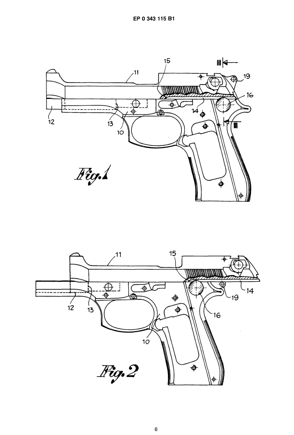
ings, in which: Figure 1 is a schematic view of the
body and bolt of a pistol, the bolt being in the
forward, closed position; Figure 2 is a view analo-
gous to that of Figure 1, but with the bolt in the
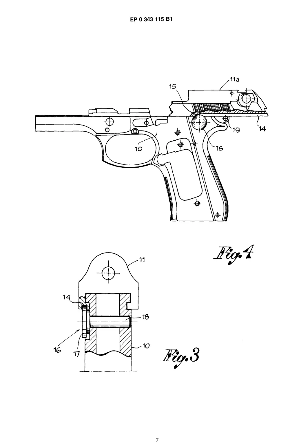
retro, open position; Figure 3 is an enlarged, sec-
tional view of the pistol, taken along arrows Ill-Ill of
figure 1; and Figure 4 is a view analogous to that of
figure 2, but with the rear portion of the bolt broken
in condition of blockage on the body of the firearm.
Referring now to the accompanying drawings,
numeral 10 represents in general the body of the
pistol and numeral 11 the bolt thereof, which is
guided and movable longitudinally forward and
back on the body 10 in manner known per so. The
bolt 11 is provided, in its front part, with an arrest-
ing or blocking portion 12 which interacts - see
figure 2 - with a fixed shoulder 13 situated on an
intermediate part of the body, so as to limit the
retro movement of the bolt. The forward movement
of the bolt is limited, instead, by its own support,
when in the closed position, as shown in figure 1.
In accordance with the invention, at least on one
side of the bolt, there is provided a longitudinal
throat 14 of limited length and, optionally, also
open in the rear part of the bolt, but, in any event,
closed toward the front of the bolt, so as to form a
striking step 15 which faces toward the back. To
the body 10, there is attached, directly or indi-
rectly, a stationary arresting element 16, which
interacts with the throat 14 and serves, in particu-
5
10
15
20
25
30
35
40
45
50
55
lar, to intercept the striking step 15. In the embodi-
ment illustrated in the accompanying drawings, the
arresting element 16 is formed by a swelling or
head 17 which is either attached to or integral with
a pivot or pin 18, mounted transversely on the
body 10 and carrying the hammer 19 of the pistol -
see figure 3. The head 17 coincides with the throat
14 of the stricking pin of the pistol and is at least
partially at level height with the striking step 15.
The length of the throat 14, or the position of the
striking step 15 and, conversely, the arresting ele-
ment 16, is such as not to interfere with the normal
longitudinal displacements of the bolt 11 - see
figures 1 and 2 - defined, toward the rear, by the
arresting portion 12 with the shoulder 13 and, to-
ward the front, by the closing support of the bolt. If,
however, for any reason whatever, the bolt is sub-
ject to breakage in back of the arresting portion 12
- see figure 4 -, the rear part 11a of the bolt, no
longer held when propelled by the gas pressure
resulting from a shell firing, is projected rearwardly
beyond its normal limit. Then, the striking step 15
comes to rest against the arresting element 16, so
as to keep safely the part 11a of the bolt attached
to the body 10, preventing the projection toward
the back against the user and achieving the safety
purpose which is the object of this invention.
Claims
1. A pistol arrangement comprising a pistol body
(10) including and upper bolt-engaging portion
with a fixed shoulder (13) adjacent to the front
end of said pistol body, and a bolt (11) guided
on the pistol body and including an arresting
portion (12) adjacent to the front end of said
bolt, with said arresting portion (12) engaging
said fixed shoulder (13) upon retromovement
of said bolt along the pistol body by propelling
gases of a shell, for limiting the retromovement
of said bolt with respect to said pistol body,
said arresting portion (12) being positioned
spaced a distance from said fixed shoulder
(13) in a pre-firing state, said distance from
said arresting portion (12) to said fixed shoul-
der (13) defining a retromovement distance,
characterized in that the bolt (11) is provided
with a lingitudinal throat (14) having a front end
providing a striking step (15) facing toward rear
end of said bolt, and in that a stationary arrest-
ing element (16) is fixed to the pistol body,
said stationary arresting element (16) including
a portion (17) projecting into said throat (14)
for engaging said striking step (15) to arrest
said bolt with respect to said pistol body in the
event of breakage of said bolt, and said portion
projecting into said throat not engaging said
striking step during normal retromovement of
3
5
ЕР 0 343 115 В1
6
said bolt along said pistol body.
2. Pistol arrangement according to Claim 1,
wherein said stationary arresting element (16)
is attached to or integral with a removable and
interchangeable element (18) mounted on the
body of the pistol, said removable and inter-
changeable element (18) being a pivot or pin
transversely mounted on the body of the pistol
and carrying the hammer therefor, and the
stationary arresting element (16) consisting of
a swelling or head (17) which is integral with
said pivot or pin and is placed in interception
position with said striking step (15) on the bolt
(11).
3. Pistol arrangement according to Claim 1,
wherein said throat (14) is open at the rear of
the bolt (11) and is interrupted by said striking
step (15) at a place intermediate the length of
the bolt.
Patentanspruche
1. Pistolenanordnung mit einem Pistolenschaft
(10), der einen am VerschluB mit einer zum
vorderen Ende des Pistolenschaftes benach-
barten feststehenden Schulter (13) angreifen-
den oberen Teil und einen am Pistolenschaft
(10) gefuhrten und einen seinem vorderen
Ende benachbarten Arretierabschnitt (12) auf-
weisenden Schlagbolzen (11) enthalt, wobei
der Arretierabschnitt (12) mit der feststehenden
Oder stationaren Schulter (13) eingreift als Fol-
ge der Ruckwartsbewegung des Schlagbol-
zens (11) entlang dem Pistolenschaft wegen
der Antriebskraft der Gase eines Geschosses,
urn die Ruckwartsbewegung des Schlagbol-
zens (11) gegenuber dem Kolbenschaft zu be-
grenzen, und wobei der Arretierabschnitt (12)
sich im Zustand vor der SchuBabgabe in Ab-
stand von der feststehenden Schulter (13) bef-
indet, welcher Abstand zwischen dem Arretier-
abschnitt (12) und der feststehenden Schulter
(13) die Strecke der Ruckwartsbewegung defi-
niert, dadurch gekennzeichnet, daB der Schlag-
bolzen (11) mit einer in Langsrichtung verlau-
fenden Kehle Oder Nut (14) versehen ist, deren
vorderes Ende eine zum hinteren Ende des
Schlagbolzens (11) hin gerichtete Anschlag-
schulter (15) bildet und daB ein feststehendes
Sperrglied (16) am Pistolenschaft (10) befestigt
ist, das einen in die Kehle Oder Nut (14) vor-
stehenden Abschnitt (17) aufweist, der an der
zum hinteren Ende des Schlagbolzens (11) hin
gerichteten Anschlagschulter (15) angreift und
den Schlagbolzen gegenuber dem Pistolen-
schaft (10) im Faile eines Bruches des Schlag-
5
10
15
20
25
30
35
40
45
50
55
bolzens arretiert, wobei der in die Kehle Oder
Nut vorstehende Abschnitt an der Anschlag-
schulter wahrend der normalen Ruckwartsbe-
wegung des Schlagbolzens entlang dem Pisto-
lenschaft nicht angreift.
2. Pistolenanordnung nach Anspruch 1, dadurch
gekennzeichnet, daB das feststehende Oder
stationare Sperrglied (16) mit einem am Pisto-
lenschaft abnehmbar und austauschbar ange-
brachte Element (18) fest verbunden Oder inte-
griert ist, das aus einem Stiff Oder Bolzen
besteht, der in Querrichtung am Pistolenschaft
montiert ist und den Hahn der Pistole tragt,
und daB das feststehende Sperrglied (16) aus
einer Verdickung Oder einem Kopf (17) be-
steht, der mit dem Stiff Oder Bolzen fest ver-
bunden ist und in einer Auffangstellung mit der
Anschlagschulter (15) am Schlagbolzen (11)
angeordnet ist.
3. Pistolenanordnung nach Anspruch 1, dadurch
gekennzeichnet, daB die Kehle Oder Nut (14)
an der Hinterseite des Schlagbolzens (11) of-
ten ist und in einem mittleren Abschnitt der
Lange des Schlagbolzens unterbrochen ist.
Revendications
1. Un pistolet est constitue par un ensemble for-
me d'une tige de pistolet (10) dont la partie
superieure presente un epaulement fixe (13)
contigu a I'extremite anterieure de ladite tige
pour retenir I'obturateur, et d'un obturateur (11)
guide sur la tige du pistolet et disposant d'un
secteur d'arret (12) contigu a I'extremite ante-
rieure dudit obturateur, ce secteur d'arret (12)
permet de stopper, avec I'epaulement fixe
(13), le mouvement de recul de I'obturateur le
long de la tige du pistolet du aux gaz de
propulsion d'un projectile, pour limiter le mou-
vement de recul de I'obturateur par rapport a
la tige du pistolet, ce secteur d'arret (12) est
distant de I'epaulement fixe (13) lorsqu'on se
trouve dans la position precedent le fir, cette
distance entre le secteur d'arret (12) et I'epau-
lement fixe (13) definit la longueur du mouve-
ment de recul, caracterise par le fait que I'ob-
turateur (11) dispose d'une rainure longitudina-
le (14) dont I'extremite anterieure forme un
cran de butee (15) tourne vers I'extremite pos-
terieure de I'obturateur, et par le fait qu'un
element d'arret fixe (16) est fixe a la tige du
pistolet, une partie (17) de cet element d'arret
fixe (16) forme une saillie dans la rainure (14)
afin d'enclencher le cran de butee (15) tourne
vers I'extremite posterieure de I'obturateur, et
de stopper I'obturateur par rapport a la tige du
4
7
ЕР 0 343 115 В1
8
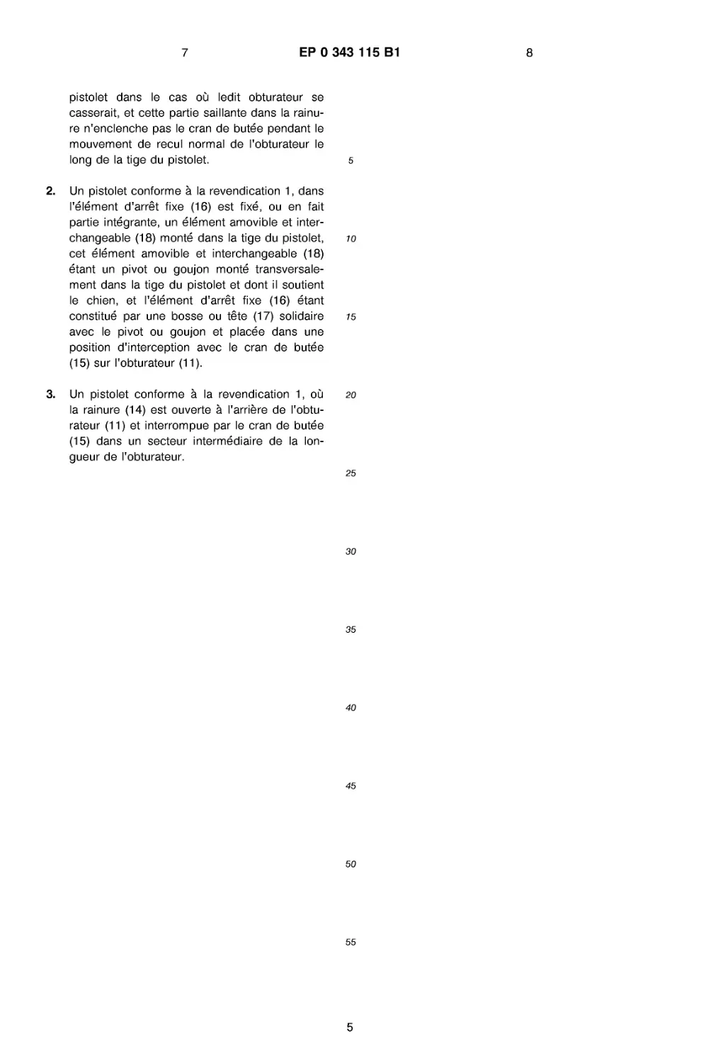
pistolet dans le cas ou ledit obturateur so
casserait, et cotte partie saillante dans la rainu-
re n'enclenche pas le cran de butee pendant le
mouvement de recul normal de I'obturateur le
long de la tige du pistolet.
2. Un pistolet conforme a la revendication 1, dans
I'element d'arret fixe (16) est fixe, ou on fait
partie integrante, un element amovible et inter-
changeable (18) monte dans la tige du pistolet,
cot element amovible et interchangeable (18)
etant un pivot ou goujon monte transversale-
ment dans la tige du pistolet et dont II soutient
le chien, et I'element d'arret fixe (16) etant
constitue par uno bosse ou fete (17) solidaire
avec le pivot ou goujon et placee dans uno
position d'interception avec le cran de butee
(15) sur I'obturateur (11).
3. Un pistolet conforme a la revendication 1, ou
la rainure (14) est ouverte a I'arriere de I'obtu-
rateur (11) et interrompue par le cran de butee
(15) dans un secteur intermediaire de la lon-
gueur de I'obturateur.
5
10
15
20
25
30
35
40
45
50
55
5
ЕР 0 343 115 В1
6
Е₽ ° 343и5 8,
7