/
Tags: weapons military affairs patent
Year: 1989
Text
Europaisches Patentamt
European Patent Office
Office europeen des brevets
12
(”) Publication number:
0 359 715 Bl
EUROPEAN PATENT SPECIFICATION
@ Date of publication of patent specification: 10.08.94 @ Int. Cl.5: F41A 5/00
@ Application number: 89830371.4
(g) Date of filing: 31.08.89
@ Device to open and close the bolt in semiautomatic pistols.
@) Priority: 12.09.88 IT 521188
@ Date of publication of application:
21.03.90 Bulletin 90/12
@ Publication of the grant of the patent:
10.08.94 Bulletin 94/32
® Designated Contracting States:
AT BE CH DE ES FR GB GR IT LI LU NL SE
@ References cited:
GB-A- 465 041
US-A- 1 744 162
GB-A-29279/1911
@ Proprietor: FABBRICA D'ARMI P.BERETTA
S.p.A.
10, Via P. Beretta
I-25063 Gardone V.T. (Brescia)(IT)
@ Inventor: Beretta, Pier Giuseppe
18, Via P. Beretta
I-25063 Gardone V. T. (Brescia)(IT)
@ Representative: Manzoni, Alessandro
MANZONI & MANZONI,
UFFICIO INTERNAZIONALE BREVETTI,
P.le Arnaldo n. 2
1-25121 Brescia (IT)
ЕР 0 359 715 В1
Note: Within nine months from the publication of the mention of the grant of the European patent, any person
may give notice to the European Patent Office of opposition to the European patent granted. Notice of opposition
shall be filed in a written reasoned statement. It shall not be deemed to have been filed until the opposition fee
has been paid (Art. 99(1) European patent convention).
Rank Xerox (UK) Business Services
(3. 10/3.09/3.3.3)
1
ЕР 0 359 715 В1
2
Description
This invention relates, in general, to
semiautomatic pistols with a barrel both rotating
and axially displaceable in the pistol stock, and
more particularly to a device designed to open a
close the bolt of said pistols.
In GB - A- 465 041 on which the preamble of
independent claim 1 is based a pistol of the above
type is disclosed which comprises: a stock includ-
ing a fixed block; a bolt positioned on said stock for
axial movement between a forward close position
and a rearward open position, a spring associated
with said fixed block biasing said bolt into said
forward close position, said bolt having a barrel!
receiving opening, a stop plane surface extending
into said opening and a longitudinal groove extend-
ing forwardly from said stop plane; a barrel! posi-
tioned in said barrel! opening of said bolt, said
barrel being axially displaceable and co-acting with
said fixed block through a screw-type connection to
cause the locking and unlocking of the barrel! and
the bolt for axial movements.
In such known pistol construction, barrel is
provided with both a locking tooth designed to
engage in the longitudinal forwardly extending
groove in the bolt, and helicoidal control bosses
which engage in curved grooves within the fixed
block. But, locking tooth and control bosses are
axially spaced each to other and thus they occupy
a certain length of the barrel. However, according
to the known execution, the only means keeping
the bolt in its closed position is the screw connec-
tion between barrel bolt, as any other positive stop
is lacking. In addition, the known opening system is
rather bulky due the axially spaced position of
locking tooth and control bosses and therefore bent
to increase the overall dimension of the pistol.
It is instead an object of the present invention
to provide a pistol with rotating and axially dis-
placeable barrel as mentioned above but with an
improved connection between barrel and bolt to
allow:
- a general reduction of the overall dimensions
of the pistol in comparision to the known
execution by reducing the dimensions of the
opening and rotating device, as locking tooth
and screw type connection coincide;
- a positive lock of the bolt on the barrel in its
closed position and during part of its opening
motion, both manually and by recoil; and
further
- to substantially delay the opening of the bolt
in order to fully exploit the gases in the barrel
for the ejection of a shot each time an am-
munition is fired, by preventing at the same
time the gas from hitting the shot on the
moment the bolt is opened.
5
10
15
20
25
30
35
40
45
50
55
Said object and advantages are fulfilled by a
semiautomatic pistol construction according to the
charactering part of claim 1.
In practice, fixed block arrangement inside the
pistol stock provides each of:
- the support of the barrel;
- the establishment of limits of the run course
of the barrel itself with respect to the axial
direction during recoil, without the presence
of any other arresting member;
- a means causing the barrel to rotate creating
a delay of the aperture registration; and
- a structure for bounding the recoil spring.
The characteristics of the invention will be
more apparent from the detailed description given
hereinafter with reference to the enclosed drawing
in which:
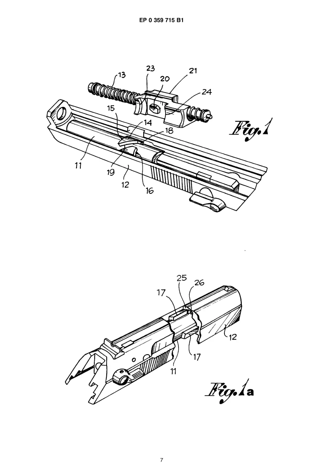
Fig.1 s hows a perspective view of the bolt
and the barrel and, separately, the
fixed block interacting with the barrel;
Fig. 1a shows a split view of the bolt with the
barrel fixed to the bolt itself;
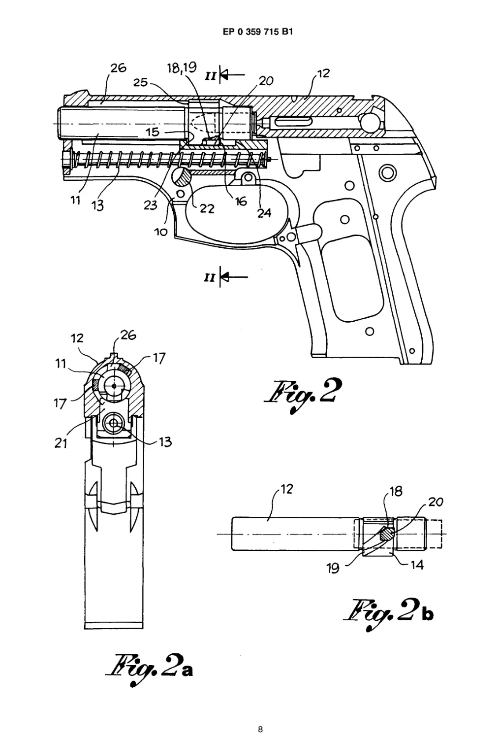
Fig. 2 shows a longitudinal section of a pis-
tol with its bolt locked in closed posi-
tion;
Fig. 2a shows a cross section on the line ll-ll
in Fig. 2;
Fig.2b shows a view of the barrel and the
tooth interacting with the relating
groove when the pistol is in the con-
dition shown in Fig. 2;
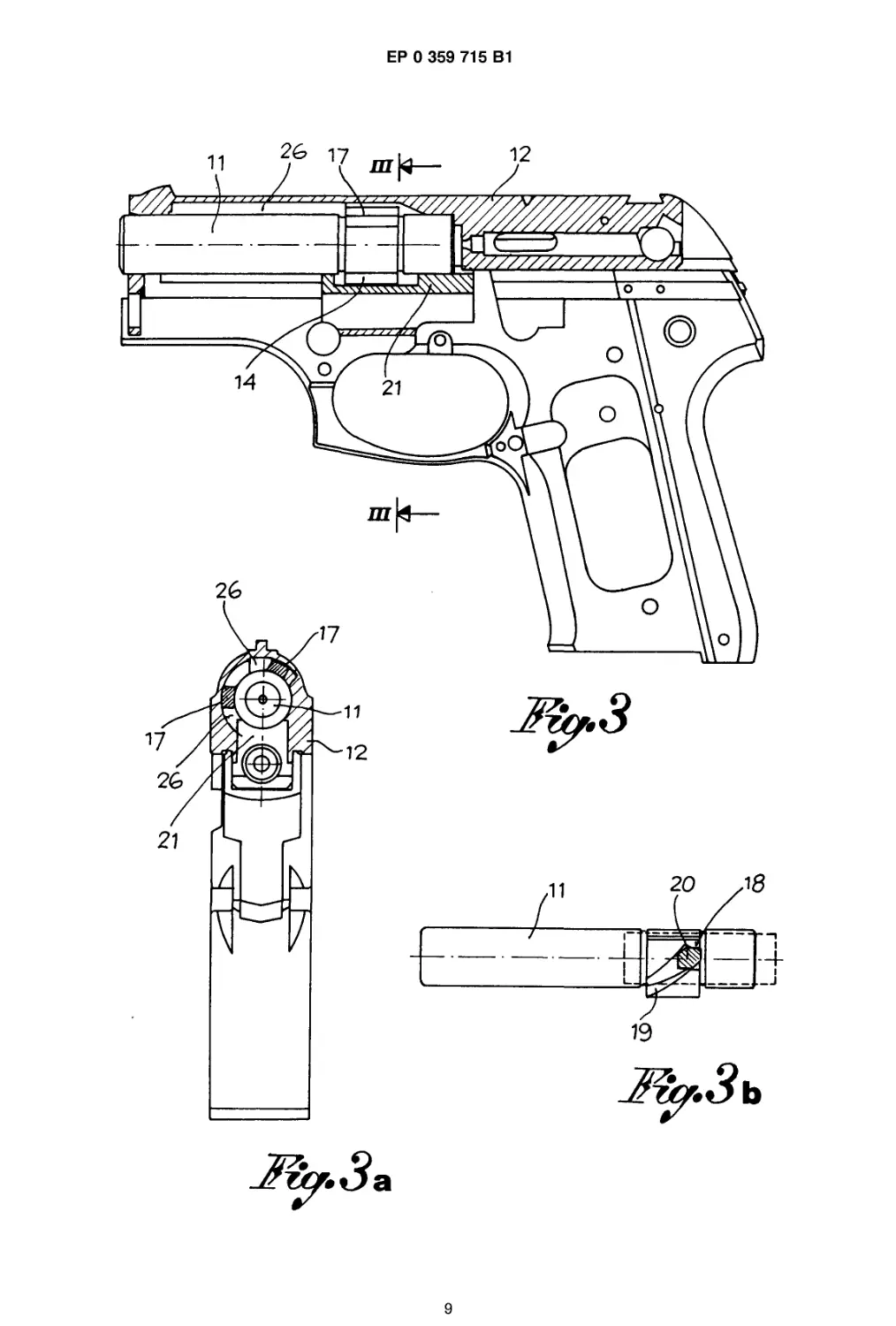
Fig. 3 shows a longitudinal section accord-
ing to Fig. 2, but with locked bolt and
barrel in rearward position;
Fig.3a shows a cross section on the line Ill-
Ill in Fig. 3;
Fig.3b shows a view of the barrel and the
tooth interacting with the relating
groove when the pistol is in the con-
dition shown in Fig. 3;
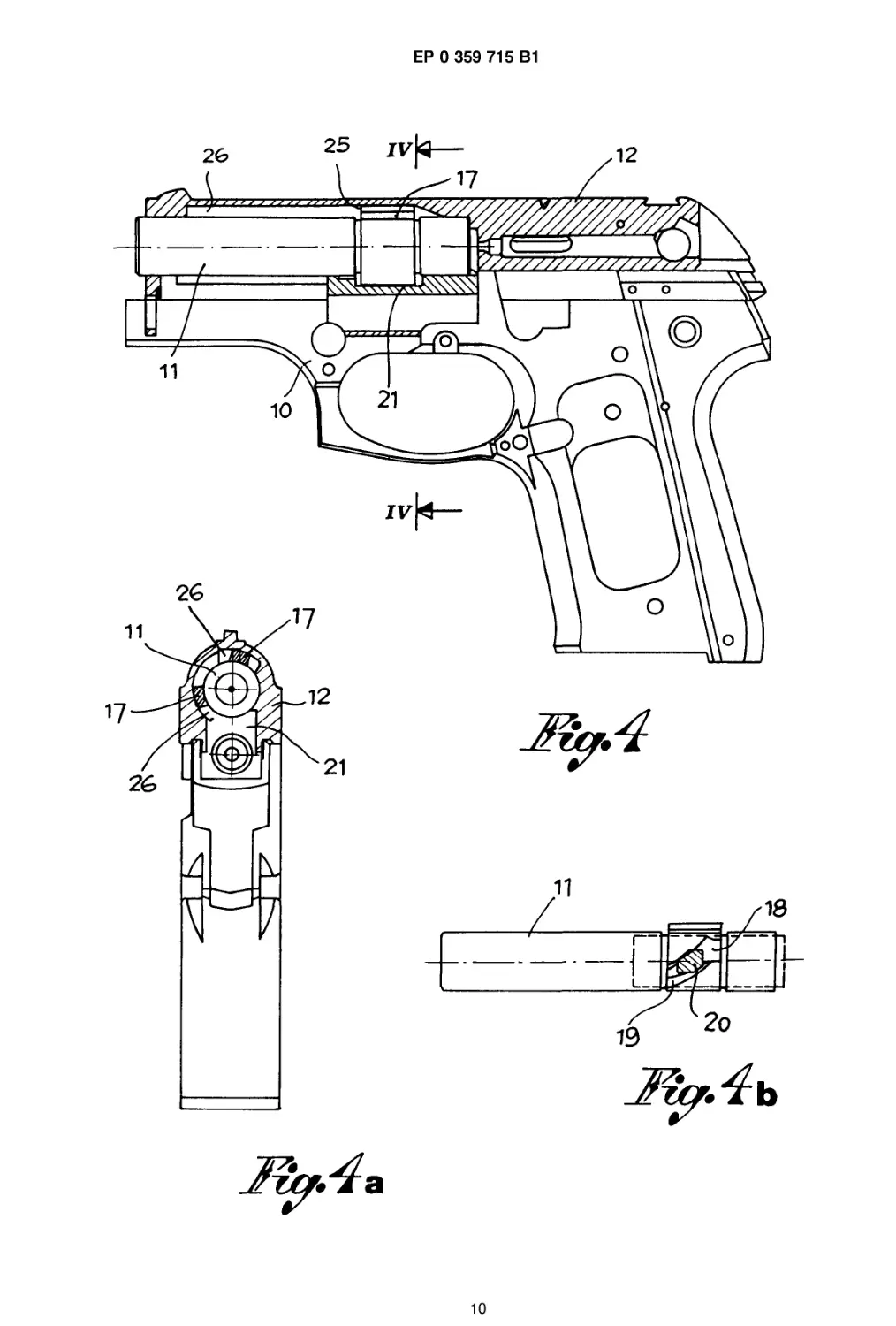
Fig. 4 shows another longitudinal section of
the pistol, but with rotating barrel
moving to the rear with the bolt;
Fig.4a shows a cross section on the line IV-
IV in Fig. 4;
Fig.4b shows a view of the barrel and the
tooth interacting with the relating
groove when the pistol is in the con-
dition shown in Fig. 4;
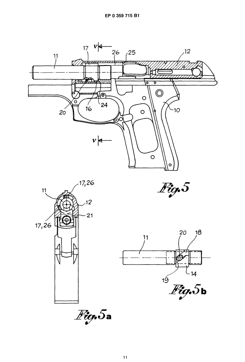
Fig. 5 shows still a longitudinal section of
the pistol, but with stationary barrel
and fully opened bolt;
Fig.5a shows a cross section on the line V-
V in Fig. 5;
Fig.5b shows a view of the barrel and the
tooth interacting with the relating
groove when the pistol is in the con-
dition shown in Fig. 5;
2
3
ЕР 0 359 715 В1
4
In a known manner, on the stock of a pistol a
barrel (11) is mounted and covered by an interact-
ing bolt (12). The barrel (11) can rotate in respect
to the bolt and to the stock and it is also displace-
able in an axial direction. The bolt (12) is able to
axially move on the stock both with the barrel and
independently to pass from a front closing position
on the barrel and an open rear position far from the
barrel. The bolt is subject to a spring (13) normally
keeping it in its front closed position, its back
motion being obtained either manually or automati-
cally by recoil forces due to the firing of о shot.
Now, according to the invention and to its
embodiment shown on the drawing, barrel (11) is
fitted in an intermediate position, with an over-
lapping section (14) with spaced front and back
stops (15, 16) on one side, and on the other side
with at least one forward directed shoulder (17)
preferably collimating with front stop (15).
In the overlapping section (14) (see Fig. 1) a
slot is cut in which, starting from the back stop (16)
has a first portion (18) which is rectilinear and
parallel to the axis of the barrel and followed by a
helicoidal portion (19) extending to the front stop
(15).
A tooth (20) which is part of a fixed block (21)
mounted on stock (10) and locked, for instance, by
a peg (20) or the like is engaged and interacts in
said slot (18,19), a spring (13) of bolt (12) longitudi-
nally and freely passing through said block (21).
Block (21) also presents on the opposite sides of
tooth (20) two axially spaced abutments (23,24)
cooperating with stop ends (15,16) on barrel (11) to
limit its axial displacements.
The coupling between slot (18,19) and tooth
(20) is such that only an axial displacement of the
barrel is possible when tooth (20) is interacting with
the rectilinear portion (18) of the slot, while the
barrel can move and simultaneously rotate as a
screw if the tooth is interacting with the helical
portion (19) while the barrel is axially displaced in
respect to block (21) bearing tooth (20).
It is pointed out that the sense of rotation of the
barrel allowing the opening of the bolt will be
opposite to that to which the barrel is subject to
when a shot is fired and to that due to it internal
rifling.
In bolt (12) a stop plane (25) is facing rear-
wards and designed to interact with shoulder (17)
of the barrel when the bolt is closed and the barrel
has moved to the front to let tooth (20) engage the
rectilinear portion (18) of the slot. Finally the bolt
presents, starting from said stop plane (25), a lon-
gitudinal and rectilinear groove (26) extending to-
wards its front to receive shoulder (17) and thus
eliminate its stopping action as soon as the barrel
has moved back and been rotated by tooth (20)
interacting with the helicoidal section (19) of the
5
10
15
20
25
30
35
40
45
50
55
slot.
Figures 2, 2a and 2b of the drawing show the
pistol with the bolt (12) moved towards the front
and thus in closed position, where it is coupled
with the barrel by means of the spring (13). In this
position:
- barrel (11) is displaced towards the front end,
with its stop (15) bearing on the abutment
(23) of the fixed block (21);
- barrel (11) is rotated to have the rectilinear
portion (18) of its slot engaged by tooth (20);
- in consequence, shoulder (17) of the barrel is
turned away from slot (26) in the bolt and
positively bearing upon stop plane (25) of the
bolt;
- thus barrel and bolt make up a solid assem-
bly in axial direction to prevent them from
moving to and from each other and ensure
the closure of the arm for its use.
Starting from this closed position, after a shot
has been fired out of the barrel and owing to the
recoil forces the bolt is opened in opposition to
spring (13) and through the following sequence:
- through a first part of the recoil correspond-
ing to the rectilinear slot (18) barrel and bolt
are displaced together without any relative
motion, the bolt taking back the barrel owing
to the interaction between stop plane (25) of
bolt (12) and shoulder (17) on barrel (11).
This intermediate condition is shown on Fig-
ures 3, 3a and 3b.
- Then, through a second part of the recoil,
barrel and bolt are still moving together, but
the barrel is simultaneously rotating due to
the interaction between tooth (20) and the
helicoidal part (19) of the slot on the barrel.
Hence, shoulder (17) on barrel (11) is an-
gularly displaced towards the relating longitu-
dinal groove (26) in bolt (12). This second
intermediate position is shown on Figures 4,
4a and 4b.
- Now, when the barrel has moved back till its
rear stop (16) is bearing against abutment
(24) of the fixed block (21), it stops rotating
and shoulder (17) falls into groove (26). Now
the barrel is standing still and the bolt goes
back to its open position represented in Fig-
ures 5, 5a and 5b allowing the ejection of the
cartridge case and the advance of the ham-
mer.
By the successive advance of the bolt the feed
of another ammunition is obtained and an inverse
sequence of the movements taking the bolt back to
its initial closed position and the arm ready for use
as shown in Fig. 2.
It is thus evident that the relative opening be-
tween barrel and bolt is delayed as it takes place
during an intermediate part of the recoil stroke of
3
5
ЕР 0 359 715 В1
6
the bolt and not at the beginnig of said stroke in
order to allow a full exploitation of the gas pressure
in the barrel for the ejection of the shot and without
any rearward gas outflow.
Claims
1. A semiautomatic pistol construction, compris-
ing a stock (10) including a fixed block (21); a
bolt (12) positioned on said stock (10) for axial
movement between a forward close position
and a rearward open position, a recoil spring
(13) associated with said fixed block (21) bias-
ing said bolt (12) into said forward close posi-
tion, said bolt (12) having a barrel receiving
opening, a rearward facing stop plane (25)
extending into said opening and a longitudinal
groove (26) extending forwardly from said stop
plane; a barrel (11) positioned in said barrel!
opening of said bolt, said barrel being axially
displaceable and co-acting with said fixed
block (21) through a screw-type connection to
cause the locking and unlocking of the barrel
and the bolt for axial movements, character-
ized in that:
- said fixed block (21) has a tooth (20)
extending toward the barrel and two ax-
ially spaced abutments (23, 24) on op-
posite side of said tooth (20),
- said barrel has a side defining a groove
(18, 19) with an initial rectilinear groove
portion (18), extending substantially par-
allel to a central axis of said barrel fol-
lowed by a helicoidal groove portion (19),
- said barrel has another side defining a
forward projection shoulder (17),
- said block tooth (20) is engaged with
said groove (18-19) of the barrel (11) as
a screw connection, whereby said barrel
rotates relative to said tooth as said tooth
engages said helicoidal groove portion
upon axial movement of said barrel, upon
rotation of said barrel said shoulder com-
ing into register with said bolt longitudi-
nal groove (26), thereby allowing said
bolt to move rearwardly to its open posi-
tion.
2. A semiautomatic pistol construction according
to claim 1, wherein said rectilinear groove por-
tion (18) followed by said helicoidal groove
portion (19) are formed cut into a section (14)
extending radially outwardly of a surface of
said barrel, said rectilinear groove portion (18)
being positioned rearwardly of said helicoidal
groove portion (19), said section (14) having
axially spaced end stops (15,16) engageable
with corresponding axially spaced abutments
5
10
15
20
25
30
35
40
45
50
55
(23-24) of said fixed block (21).
3. A semiautomatic pistol construction according
to claim 1 or 2, wherein said bolt (12) and
barrel (11) recoil together upon firing of the
semiautomatic pistol for a first part of an open-
ing stroke as stop plane (25) in the bolt en-
gages forward projecting shoulder (17) of the
barrel, and barrel is connected (18,19,20) to
said fixed block for allowing a first stroke part
upon recoil in which said bolt and barrel are
displaced with respect to said stock without
any relative motion and a second stroke part in
which said barrel rotates with respect to said
bolt allowing said bolt to move indipendent
rearwardly into its open position and for limit-
ing the axial movement of said barrel.
Patentanspruche
1. Eine semiautomatische Pistole, welche umfaBt
ein Griffstuck (10) mit einem festen Block (21);
ein SchloB (12), das sich auf dem genannten
Griffstuck (10) befindet und das sich axial zwi-
schen einer vorderen geschlossenen Stellung
und einer hinteren offenen Stellung bewegen
laBt; eine mit dem genannten festen Block (21)
verbundene Ruckholfeder (13), urn das ge-
nannte SchloB (12) in die vordere geschlosse-
ne Stellung zu drucken, wobei das genannte
SchloB (12) aufweist eins Offnung fur den Lauf;
(eine hintenliegende und in die genannten Off-
nung ausgedehnte Halteebene (25); eine
Langsnut (26), die von der genannten Haltee-
bene nach vorne fiihrt; einen Lauf (11), der
sich in der genannten Laufoffnung des ge-
nannten Schlosses befindet, wobei der ge-
nannte Lauf axial verschiebbar ist und zusam-
men mit dem genannten festen Block (21)
durch eine Schraubverbindung zusammen-
wirkt, urn einen AnschluB und ein Losen des
Laufs und des Schlosses fur axiale Bewegun-
gen erlaubt,
dadurch gekennzeichnet, daB
- der genannte feste Block (21) einen Zahn
(20) aufweist, der sich zum Lauf und zu
zwei axial angeordneten Widerlagern (23,
24) auf dar dem Zahn (20) gegenuberlie-
genden Seite erstreckt,
- der genannte Lauf eins eine Nut (18, 19)
bildende Seite mit einem gradlinigen An-
fangsnutabschnitt (18) aufweist, der sich
im westlichen parallel zur Mittelachse
des genannten Laufs erstreckt und von
einem schraubenformigen Nutabschnitt
(19) gefolgt wird,
- daB der genannte Lauf eine weitere Seite
aufweist, die eine Vorschuhabsatz (17)
4
7
ЕР 0 359 715 В1
8
bildet,
- der genannte Blockzahn (20) in die ge-
nannten Nut (18, 19) des Laufs (11) als
Schraubverbindung eingreift, wobei der
genannte Lauf sich gegenuber dem dem
genannten Zahn dreht, wahrend der ge-
nannte Zahn durch axiale Bewegung des
genannten Laufs in den genannte schrau-
benformigen Nutabschnitt eingreift, wo-
bei infolge der Drehung des Laufs der
genannte Vorschubabsatz mit der ge-
nannten Langsnut (26) des Schlosses zu-
sammenfallt und so dem genannten
SchloB die Ruckwartsbewegung in die
offene Stellung erlaubt,
2. Eine semiautomatische Pistole gemaB dem
Anspruch 1, wobei der genannte gradlinige
Nutabschnitt (18) und der folgende schrauben-
formige Nutabschnitt (19) in ein Profil (14) ein-
gepaBt sind, welches sich radial nach auBer-
halb der Oberflache des genannten Laufs aus-
dehnt, wobei sich der gradlinige Nutabschnitt
(18) hinter dem schraubenformigen Nutab-
schnitt (19) befindet und wobei das genannte
Profil (14) axial angeordnete Halteebenen (15,
16) aufweist, die in entsprechende axial ange-
ordnete Widerlager (23, 24) des genannten fe-
sten Blocks (21) eingreifen.
3. Eine semiautomatische Pistole gemaB An-
spruch 1 odor 2, wobei das genannte SchloB
(12) und der genannte Lauf (11) nach dem
AbschieBen der semiautomatischen Pistole fur
einen ersten Tell einer Offnungsbewegung zu-
sammen zuruckschlagen, wahrend der die Hal-
teebene (25) im SchloB in den sich nach vorne
erstreckenden Vorschubabsatz (17) des Laufs
eingreift und der Lauf an dem genannten fe-
sten Block verbunden (18, 19, 20) wird, urn
einen ersten Toil der Ruckschlagbewegung zu
erlauben, wahrend das genannte SchloB und
der genannte Lauf sich gegenuber dem Griff-
stuck ohne relative Bewegung verschieben und
einen zweiten Toil der Bewegung, wahrend
dem der Lauf sich gegenuber dem genannten
SchloB dreht und diesem so erlaubt, sich un-
abhangig zuriick in seins offene Stellung zu
bewegen und die axiale Bewegung des ge-
nannten Laufs zu verringern.
Revendications
1. Pistolet semi-automatique comprenant un fut
(10) avec un bloc fixe (21), uno culasse (12)
positionnee sur ledit fut (10) pour la deplace-
ment axial entre la position avant de verrouilla-
ge et la position arriere de deverrouillage, un
5
10
15
20
25
30
35
40
45
50
55
ressort de recul (13) associe a co bloc fixe
(21) qui pousse ladite culasse (12) vers I'avant
dans la position de verrouillage; cotte culasse
(12) comprend uno ouverture pour le canon, un
plan d'arret (25) oriente vers I'arriere et s'eten-
dant dans I'ouverture et uno rainure longitudi-
nale (26) s'etendant on avant a partir du plan
d'arret; un canon (11) positionne dans ladite
ouverture de la culasse; co canon qui so de-
place on direction axiale et interagit avec le
bloc fixe (21) selon uno liaison du type a vis,
permet le blocage et le deblocage du canon et
de la culasse ainsi quo les deplacements
axiaux, caracterise on co quo:
- co bloc fixe (21) comporte uno dent (20)
qui s'etend vers le canon, et des epaule-
ments (23, 24) espaces on direction axia-
le sur les cotes opposes de la dent (20);
- un cote de canon est rainure (18, 19); la
partie initiale comporte uno rainure recti-
ligne (18) essentiellement parallele a
I'axe central du canon, tandis quo la par-
tie suivante comporte uno rainure helicoT-
dals (19);
- I'autre cote du canon comporte un epau-
lement on saillie vers I'avant (17);
- la dent (20) du bloc s'engage dans la
rainure (18, 19) du canon (11) telle uno
vis, jusqu'a co quo co canon tourne par
rapport a la dent pondant quo cotte der-
niere s'engage dans la rainure helicoYda-
le grace au mouvement on direction
axiale du canon; par la rotation du canon,
ledit epaulement coincide avec: la rainu-
re longitudinale (26) de la culasse et
permet ainsi a ladite culasse de so de-
placer on arriere jusqu'a la position de
deverrouillage.
2. Pistolet semi-automatique selon la revendica-
tion 1, caracterise on co quo la partie compre-
nant la rainure rectiligne (18), suivie par la
rainure helicoYdale (19) est coupee on uno
section (14) qui s'etend on etoile vers I'exte-
rieur de la surface du canon, la partie avec
rainure rectiligne (18) etant positionnee a I'ar-
riere de la partie avec rainure helicoYdale (19),
ladite section (14) etant munie d'arrets termi-
naux espaces on direction axiale (15, 16) pou-
vant s'engager dans les epaulements corres-
pondants espaces on direction axiale (23, 24)
du bloc fixe (21).
3. Pistolet semi-automatique selon les revendica-
tions 1 ou 2, caracterise on co quo la culasse
(12) et le canon (11) reculent ensemble apres
le coup de feu pour uno premiere partie de la
course de deverrouillage, tandis qu'un plan
5
9
ЕР 0 359 715 В1
10
d'arret dans la culasse engage I'epaulement
du canon s'etendent vers I'avant (17), et la
canon est relie (18, 19, 29) a ce bloc fixe pour
permettre une premiere partie de la course de
recul pendant laquelle la culasse et le canon 5
se deplacent par rapport au fut sans mouve-
ments relatifs, et une seconde partie de la
course pendant laquelle le canon tourne par
rapport a la culasse et permet ainsi a celle-ci
un deplacement independant vers I'arriere ю
dans la position de deverrouillage et de limiter
egalement le mouvement en direction axiale
du canon.
20
25
30
35
40
45
50
55
6
1
8
EP°3S9
?1SB1
9
ЕР 0 359 715 В1
10
ЕР 0 359 715 В1
11