/


Tags: weapons military affairs patent
Year: 1976


Text
United States Patent [19]
Hartmann
[in 3,998,125
[45] Dec. 21, 1976
[54] BELT FEEDER FOR AN AUTOMATIC
WEAPON
[75] Inventor: Rolf Hartmann, Dusseldorf,
Germany
[73] Assignee: Rheinmetall GmbH, Dusseldorf,
Germany
[22] Filed: July 29, 1974
[21] Appl. No.: 492,874
[30] Foreign Application Priority Data
Aug. 3, 1973 Germany ........... 2339311
[52] U.S. Cl........................ 89/33 CA
[51] Int. Cl.2....................... F41D9/02
[58] Field of Search ... 89/33 BA, 33 BC, 33 CA
[56] References Cited
UNITED STATES PATENTS
317,161 5/1885 Maxim .............. 89/33 CA
863,101 8/1907 Schwarzlose ........ 89/33 CA
Primary Examiner—Stephen C. Bentley
Attorney, Agent, or Firm—Ernest G. Montague; Karl F.
Ross; Herbert Dubno
[57] ABSTRACT
A belt feeder for loading an ammunition belt into an
automatic weapon has a feeder starwheel driven step-
wise in dependence on the weapon function and is
provided with an ammunition-belt inlet-chute which
progressively narrows in a substantially spiral fashion
and extends angularly around the feeder starwheel over
approximately 90°.
3 Claims, 6 Drawing Figures
U.S. Patent Dec. 21, 1976
Sheet 1 of 4
3,998,125
Prior Art
U.S. Patent Dec. 21, 1976
Sheet 2 of 4
3,998,125
U.S. Patent Dec. 21, 1976
Sheet 3 of 4
3,998,125
ZZZZZZZZZZZZZZZZZZZZZZZZZ.
U.S. Patent Dec. 21, 1976
Sheet 4 of 4
3,998,125
5
FIG. 6
3,998,125
BELT FEEDER FOR AN AUTOMATIC WEAPON
FIELD OF THE INVENTION 5
The invention relates to a belt feeder for automatic
weapons, particularly machine guns and machine ca-
nons driven in a stepwise manner by a feeder starwheel
operated by gas pressure or other means in dependence
on the requirements of the weapon. 10
BACKGROUND OF THE INVENTION
In machine guns of conventional types the ammuni-
tion belt is continuously subjected to brief and rela-
tively large accelerations, leading to considerable stress 15
on the belt and thereby causing an elongation or
stretching thereof within the elastic range of the belt
members, resulting in a change of the desired separa-
tion distance between cartridges or shells carried by the
belt. This frequently causes either functional distur- 20
bances in the case of known starwheel feeders, the belt
on the cartridge becoming jammed between the star-
wheel feeder and the wall of the belt inlet as a result of
such changed separation distances between the car-
tridges or shells, or results in unfavorable force-trans- 25
mission ratios between the teeth of the starwheel feeder
and the cartridges or shells. This danger is increased if,
for example, belt lengths of the order of 1 to 2 meters
are required to be pulled in by the starwheel feeder.
Rotary bending or overlapping of the belt from the 30
munition supply to belt feeder also causes increased
pulling forces to be applied to the belt which, together
with the stepwise accelerations to which the belt is
subjected, cause an elongation thereof, the cartridges
being thereby additionally displaced m a longitudinal 35
direction with respect to the belt members enveloping
them. For this reason it has been customary to date to
provide centering adjustments ahead of the belt feeder,
in which the cartridges are made to resume their origi-
nal position to ensure a disturbance-free entrance into 40
the belt feeder.
OBJECTS OF THE INVENTION
It is therefore an object of my invention to obviate
the above disadvantages and to improve a belt feeder of 45
the aforesaid type to obtain a satisfactory entrance of
the munition belt into the belt feeder and thereby en-
sure a trouble-free ammunition supply to the weapon
even when the belt is subjected to large pulling forces.
SUMMARY OF THE INVENTION
A belt feeder for loading an ammunition belt into an
automatic weapon has feeder and transport starwheels,
the transport starwheel being in the same plane as the
feeder starwheel, driven synchronously in a stepwise 55
fashion and engaging cartridges on a belt; it is also
provided with an ammunition belt inlet chute which
progressively narrows in a substantially spiral fashion
and encompasses the feeder starwheel over approxi-
mately 90°. The ammunition belt, which advances in 60
dependence on the weapon function, has belt members
for strapping cartridges thereon, the cartridges being
unstrapped from the belt prior to entering the weapon.
The inlet chute is formed on its top sides with wedge-
shaped inlet surfaces and guiding edges for guiding the 65
cartridges and belt members. Special centering ar-
rangements are no longer required; the invention is
applicable to starwheel belt-feeders having both a di-
50
rect cartridge supply, where strapped cartridges are fed
directly to an outlet being displaced by the breech in a
longitudinal direction and made to leave an encom-
passing belt member, and an indirect cartridge supply
where the strapped cartridges are already ejected
within the region of the starwheel from the respective
belt members and arrive separately at an outlet slit.
Stretching of the belt and a consequent increase of the
separation distance is avoided by the starwheel engag-
ing the respective cartridges and guiding them along a
narrowing guide path where the separation of the car-
tridges takes place.
BRIEF DESCRIPTION OF THE DRAWING
These and other features of the invention will be
better understood with reference to the accompanying
drawing in which:
FIG. 1 diagrammatically illustrates a feeder starwheel
of the prior art in fragmentary elevational cross-sec-
tion;
FIG. 2 is a similar view which illustrates the increased
separation distance due to a conventional starwheel
feeder of the type illustrated in FIG. 1;
FIGS. 3 and 4 are diagrams which illustrate the im-
provements obtainable according to the invention in
views corresponding respectively to FIGS. 1 and 2;
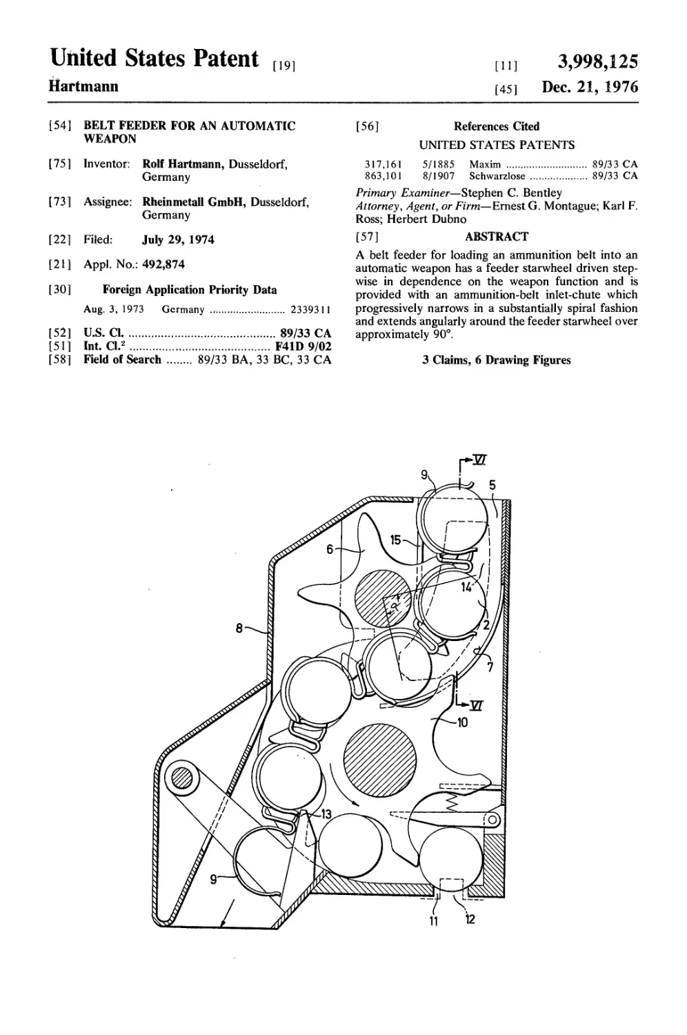
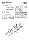
FIG. 5 is a fragmentary elevational view of a belt
feeder having two starwheels and the unstrapping of
the cartridges; and
FIG. 6 is a fragmentary cross-section of FIG. 5 along
line VI — VI.
SPECIFIC DESCRIPTION
FIGS. 1 and 2 show in schematic fashion the opera-
tion of a conventional belt feeder for a weapon. A belt
containing shells or cartridges 2, which are kept at a
normal or separation distance from each other, is fed
through a chute 3, and a feeder starwheel 1 is driven
stepwise in dependence on the weapon function in the
direction of the arrow shown to advance the belt. Belt
members 9 have been omitted for clarity’s sake from
FIGS. 1 and 2, although they have been shown in FIG.
5. The outer wall of chute 3 having a width w, corre-
sponding roughly to the diameter of shells 2, assumes a
part-circular shape in the vicinity of starwheel feeder 1,
the chute having a radius R approximately equal to the
root radius of the starwheel plus twice the radius of the
shell.
As a result of increased belt tension an increased
separation distance between shells may result which is
depicted in FIG. 2. It is obvious that an unfavorable
force-transmission-ratio between shell 2' and the tooth
of the starwheel making contact with the latter will
result, which may in turn lead to the aforesaid func-
tional disturbances of the feeder starwheel and the
weapon.
FIGS. 3 and 4 show a similar situation using a chute
5 formed according to my invention. Chute 5 is initially
wider than chute 3, but is made to be progressively
narrower over a region or central angle a of about 90°
encompassing starwheel 6, finally reaching the diame-
ter of shell 2. The part-circular shape of outer wall 7
now has a radius Rt approximately equal to the radii of
starwheel 6 plus that of the shell and the incremental
width of chute 7 exceeding that of chute 3, that incre-
mental width amounting to about 20 to 25% of the
diameter of the cartridge or shell.
3,998,
3
Cartridges or shells 2 contained within a belt not
illustrated in FIGS. 3 and 4 are separated by a distance
a. As a result of a considerable force acting on the belt
the latter is stretched, increasing the separation dis-
tance to a length b, with cartridges 2 consequently 5
assuming positions shown dotted in FIG. 3. Upon rota-
tion of starwheel 6, cartridges 2 bordering wall 7 are
engaged by the teeth of starwheel 6 as illustrated in
FIG. 4, thereby sliding the former along wall 7, the
latter progressively narrowing the width of chute 5 and 10
therefore reducing the cartridge separation-distance to
the original separation distance a.
FIG. 5 shows a starwheel belt feeder, where the car-
tridges or shells are unstrapped prior to being loaded
onto the weapon. The belt, being made up of belt mem- 15
bers 9 carrying cartridges or shells 2, is introduced to
the belt feeder through chute 5. In a housing 8 of the
belt feeder there is arranged in a plane parallel to
feeder starwheel 6 a transport starwheel 10. Starwheels
6 and 10 are always coupled to each other through a 20
cartridge 2 still attached to the belt, so that the star-
wheels are therefore effectively driven synchronously,
necessitating a drive for only one of the starwheels.
Prior to reaching a discharge slit 11, where cartridges 2
are dispatched by a breech 12 to the loading chamber 25
of the weapon, which is not shown in FIG. 5, the former
are stripped from the belt in a conventional manner at
a location 13, belt members 9 being tangentially slid
off, and cartridges 2 being discharged therefrom by the
rotation of starwheel 10. The top sides of chute 5 are 30
formed within the region of feeder starwheel 6 with
wedge-shaped inlet surfaces 14 and guide edges 15 for
guiding belt members 9 and cartridges 2, belt members
9 being thereby centered to an appropriate position
requisite for guiding the latter in a disturbance-free 35
fashion.
125
4
I claim:
1. A belt feeder for loading an ammunition belt into
an automatic weapon having a feeder starwheel driven
stepwise in dependence on the weapon function com-
prising an ammunition-belt inlet-chute progressively
narrowing in a substantially spiral fashion and encom-
passing said feeder starwheel over about 90°, said car-
tridges being unstrapped from said belt prior to enter-
ing said weapon, and a transport starwheel in a plane
parallel to that of said feeder starwheel and synchro-
nously driven therewith, said starwheels engaging each
other via a belt-strapped cartridge.
2. A belt feeder as defined in claim 1 wherein said
inlet chute has sides formed with wedge shaped inlet
surfaces and guide edges for guiding said cartridges and
said belt.
3. A belt feeder for an automatic weapon having a
starwheel driven stepwise to advance a munitions belt
carrying a succession of cartridges, the improvement
which comprises a wall spaced from and extending
arcuately over an angle of about 90° about the periph-
ery of said starwheel and defining and inlet chute for
said cartridges having an inlet end and an outlet end,
said wall having generally the configuration of a spiral
progressively approaching said starwheel from said
inlet end to said outlet end, and a transport starwheel
lying in a plane parallel to the first-mentioned star-
wheel and having teeth overlapping the teeth of said
first starwheel laterally adjacent said first starwheel,
said starwheels being driven synchronously, said star-
wheels being constructed and arranged to simulta-
neously engage a common cartridge thereby entraining
one of said starwheels with the other.
*****
40
45
50
55
60
65