/


Tags: weapons military affairs patent
Year: 1954

Text
Feb. 16, 1954
В. MAILLARD
2,669,160
BELT FEED FOR FIREARMS
Filed June 13, 1949
2,669,160
B. MAILLARD
BELT FEED FOR FIREARMS
Feb. 16, 1954
Filed June 13, 1949
2 Sheets-Sheet 2
Patented Feb. 16, 1954
2,669,160
UNITED STATES PATENT OFFICE
2,669,160
BELT FEED FOR FIREARMS
Bernard Maillard, Geneva, Switzerland, assignor
to the Society “Brevets Aero-Mecaniques,”
S. A., Geneva, Switzerland, a society of Switzer-
land
Application June 13, 1949, Serial No. 98,736
Claims priority, application Luxembourg
June
2 Claims.
1
The present invention relates to semi-auto-
matic firearms the reloading of which takes place
automatically but with which the gunner must
operate the trigger upon every shot, automatic
firearms firing by bursts and arms capable of
working either in a semi-automatic or in a fully
automatic manner, these firearms including a
movable breech piece having a reciprocating mo-
tion in a direction substantially parallel to that
of the firing axis of the arm. It is more particu-
larly concerned with arms of this kind supplied
with ammunition from a flexible belt on which
the cartridges are disposed at regular intervals
of a value hereinafter called the “pitch” of the
belt, said belt being actuated by a feeding device
operated by the movable breechblock of the arm
in such manner that the forward movement of
the belt takes place by successive steps equal to
fractions of the pitch and in particular to one
half thereof.
According to a feature of my invention, in a
firearm provided, for the discontinuous drive of
the cartridge belt by a feeding device operated
step by step by the movable breechblock so that
two successive steps correspond to a total feed dis-
placement of an amplitude equal to the pitch and
take place, respectively, the first one during the
recoil stroke of said breechblock and the second
one at the end of the frontward return stroke
thereof, I arrange a camming mechanism
through which said feeding device is operated by
the movable breechblock, in such manner that
the' first step begins only after said breechblock
has moved through a substantial portion of its re-
coil stroke, whereby, in particular, I reduce the
path of travel during which the nose of the 35
breech piece rubs along the lower generatrix of
the cartridge brought along the axis of the arm
by the first step.
Preferred embodiments of the present inven-
tion will be hereinafter described with reference 4
to the accompanying drawings, given merely by
way of example and in which:
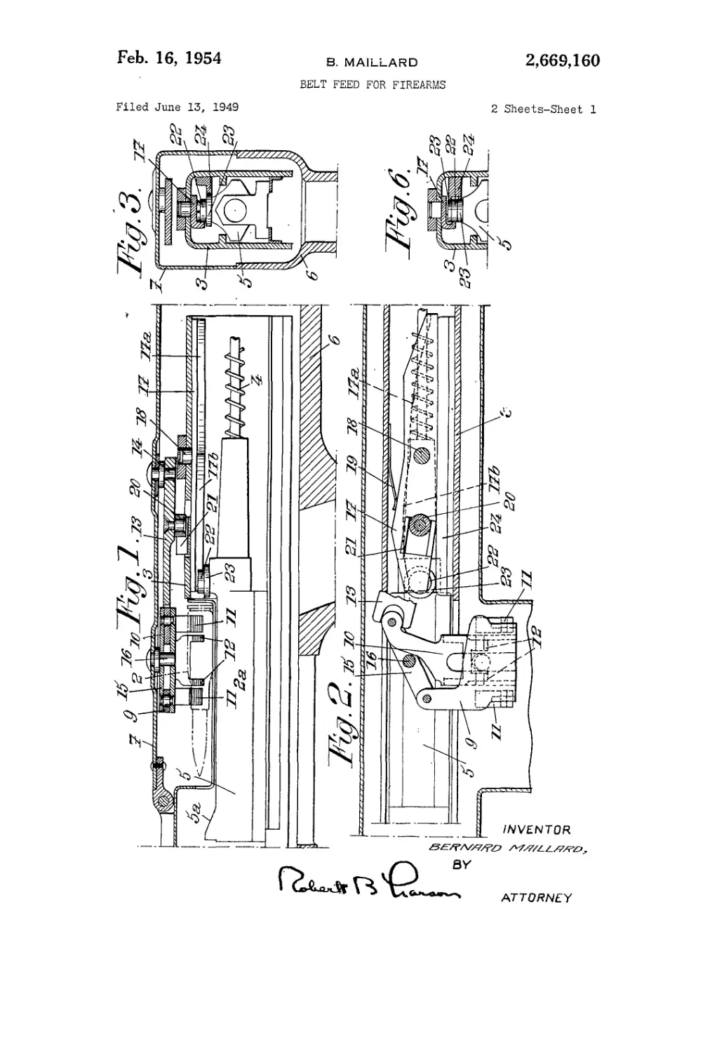
Figs. 1 to 4 show, respectively in vertical sec-
tion, in top view with parts in section and parts
cut away, and in cross sections in two different 45
respective vertical planes, an automatic firearm
made according to the invention;
Fig. 5 diagrammatically shows, in four differ-
ent operating positions, certain parts of the feed 50
device included in the arm shown by Figs. 1 to 4;
r Fig. 6 is a transverse half-section of a first
construction of the device operated by the mov-
able breechblock for actuating the feeding de-
19, 1948
(Cl. 89—33)
2
Figs. 7 and 8 show, respectively in cross section
and in longitudinal section on the line VIH—VTH
of Fig. 7, a second construction.
In the following description, it will be sup-
5 posed that the invention is applied to a machine-
gun, fed with cartridges by means of a belt I
on which are fixed cartridges 2, the forward
movement of the belt taking place in a discon-
tinuous manner, by successive steps equal each
10. to one half of the pitch, under the action of a
feeding device. \
This firearm includes, in the usual manner, a
barrel (not shown on the drawings) connected
at the rear with a breech casing 3 in which moves,
15 against the action of a recuperator spring 4, a
movable breechblock 5 provided, at its'upper
front end, with a nose 5a capable of introducing
into the barrel cartridge chamber, during the re-
turn stroke of the breechblock, the cartridge
20 brought along the axis of said chamber by the
belt feeding mechanism (feeding device), which
is to be more explicitly described hereinafter.
The whole of the barrel and of breech casing
3 is supported by a stock 6 with respect to which
25 said whole is given a reciprocating motion (re-
coil movement and return movement) during the
operation of the firearm.
I mount on said stock a cover 7, intended to re-
ceive the feeding device, and a feed guide 8, the
latter supporting the belt ’ I and being provided
with a gap in its middle portion to permit pas-
sage, between two introduction edges 8a, of the
breechblock nose 5a during’the step of introduc-
tion of the cartridge into the arm barrel.
It should be noted here that cover 1 does not
participate in the recoil movement of breech
casing 3 and that, due to the fact that it is sta-
tionary, it is particularly adapted, to act as sup-
port for the feeding device intended to move
belt (.
This feeding device is arranged to. produce a
discontinuous step by step movement, of said belt,
the movement of one cartridge over a distance
equal to the pitch therefore taking place in two
steps, to wit a preparatory step of. an amplitude
equal to one half-pitch, the effect of which is
to bring this cartridge into a waiting position
(shown for cartridge 2 in the Diagram I of Fig.
5), and a complementary step, also of one half-
pitch, ensuring the passage of said cartridge from
this waiting position to the introductory posi-
tion (shown at 2 on the Diagram HI of Fig. 5).
For a predetermined cartridge, the preparatory
step and the complementary step above referred
to..overlap;;;tv(Su
а,ввд,1во
3
(backward and forward strokes of breechblock 5),
every full reciprocation of said breechblock pro-
ducing first the complementary step relative to
the cartridge which is in waiting position and the
introduction of this cartridge into the cartridge
chamber and, then, the preparatory step rela-
tive to the next cartridge which is thus brought
into waiting position.
The cycle of operation of the feeding device
having thus been defined in a general manner,
according to the main feature of my invention,
said device is controlled by breechblock 5 in such
manner that the complementary step of a car-
tridge in waiting position takes place during the
breech recoil stroke and begins only after said
breechblock has travelled through a substantial
portion of this recoil stroke.
In this way, and contrary to what took place
with the already known feeding device of the
same kind, for which the complementary step
took place immediately upon the beginning of
the breechblock recoil stroke, I avoid rubbing
of the nose 5a of said breechblock over the whole
length of the lower generatrix of the cartridge
fed into position of introduction, between the
edges 8a of passageway 8, by said supplementary
step.
In particular, if cartridge 2 is brought into
introductory position only after the nose 5a of the
breechblock has moved past the rear of the neck
2a of the cartridge case, any risk of deteriorat-
ing this relatively weak portion of said cartridge
case is avoided.
For instance, in the case of cartridges of the
usual type, the beginning of the complementary
step may correspond to breechblock 5 having
already moved a distance equal to two thirds of
its recoil stroke.
It seems particularly advantageous to make
the feeding device according to the embodiment
illustrated by the drawings.
Such a device includes two sliding members
9 and 10 carried by cover 7 and capable of mov-
ing transversely with respect to the axis of the
firearm, these sliding members being fitted with
respective pawls 11 and 12, said pawls being each
retracted against the action of a spring (not
shown) when the corresponding sliding member
moves in a direction opposed to the direction of
feed of belt I and coming on the contrary to
catch a cartridge and to drive said belt over a
distance corresponding to one half of the pitch
when said sliding member is moved in the direc-
tion of forward feed of the belt.
Sliding members 9 and 10 are controlled by an
oscillating lever 13 hinged about'a pivot axis 14
on cover 7, and connected to said sliding members
in such manner that they move in opposite direc-
tions to each other, for which purpose, for in-
stance, sliding member 10 is directly acted upon
by the front end of lever 13 and there is inter-
posed between said end and sliding member 9 a
link 15 pivotally mounted on cover 7 about an
axis 16 located substantially opposite the middle
point of said link.
Oscillating lever 13 is driven by movable
breechblock 5 by means of a camming mecha-
nism including a cam 17 pivoted (about axis 18)
to breech casing 3 and subjected to the action
of a return spring 19 intended to keep said cam
in correct position when said cover is closed.
Connection between cam 17 and lever 13 takes
place through a device adapted to permit recoil
movement of breechblock casing 3 with respect
to cover 7, for instance through the intermediate
5
10
15
20
25
30
35
40
45
50
55
60
65
70
75
4
of a roller 20 carried by said lever 13 and mov-
ing between guides 21 rigid with cam 17.
A cam follower constituted by a roller 22 is
mounted on breechblock 5 opposite cam 17, the
active portions of said cam being arranged in
such fashion that, on the one hand, the com-
plementary step of a cartridge in waiting posi-
tion takes place after the breechblock has moved
a distance corresponding to a substantial por-
tion of its recoil stroke (active portion 17a) and,
on the other hand, the preparatory step corre-
sponding to the next cartridge takes place at the
end of frontward return of said breechblock (ac-
tive portion 17b).
The whole of the active portions 17a (corre-
sponding to the end of the recoil stroke of the
breechblock) and 17b (corresponding to the
second fraction of its return stroke) therefore
has a characteristic curve with a double con-
cavity which is shown by a reinforced line on
the diagrams of Fig. 5, points Га. and гь of this
curve (which might possibly coincide together)
corresponding respectively to the beginning of
the intervention of active portion 17 a during the
recoil stroke of movable breechblock 5 and of ac-
tive portion 17b during the return stroke of said
movable breechblock.
I will now indicate in a more detailed manner
and with reference to the diagrams of Fig. 5, the
various phases of operation of the feeding device
above described.
Considering the firearm just when a cartridge
previously introduced into the cartridge cham-
ber is fired (Diagram I, the next cartridge 2 is in
waiting position and roller 22 in contact with
the front end of the active portion 17b of cam 17.
During the first fraction of the recoil stroke of
the breechblock and up to the time when roller
22 moves past point ra, the position of cam 17
remains unchanged since said roller remains
practically away from said active portion 17b;
the nose 5a of the breechblock therefore moves
freely toward the rear between the edges 8a of
passageway 8. On the contrary, from this time
on, roller 22 attacks the active portion 17a and
causes cam 17 to swing (positions at the begin-
ning of this attack and position at the end of the
recoil stroke represented respectively by Dia-
grams II and III). This phase corresponds to
the complementary step which brings cartridge
2 between the edges 8a, i. e. across the path of
travel of the nose 8a of the breechblock;
during the first portion of the return stroke
of the breechblock 5, cartridge 2 is extracted
from the belt -which is stationary and is in-
troduced into the cartridge chamber; when roll-
er 22 moves past point rD and only from
this time on, the active portion 17b is acted upon
and cam 17 is returned (position shown by
Diagram IV) into the position it occupied
initially (Diagram I), this phase of the opera-
tion corresponding to the preparatory step
for the next cartridge, which cartridge is then
brought into waiting position at a distance from
the firing axis equal to one half of the pitch. The
various elements of the arm are then back into
their initial position and the cycle is repeated
upon the next recoil stroke of the breechblock.
With such an arrangement, the recoil move-
ment of the breechblock is braked only for a
relatively short time, due to the fact that the
cartridge is brought relatively late into intro-
ductory position.
Furthermore, as already stated, this arrange-
2,669,160
5
ment practically eliminates any risk of deteriora-
tion of the cartridges by the breechblock nose.
Finally, I avoid any risk of wedging of the
breechblock by the feeding device if, for any ac-
cidental cause, said breechblock has moved back-
ward to a distance non negligible but however
insufficient for catching the cartridge, in which
case, for an arm fitted with a feeding device of
a conventional type which starts bringing the
cartridge into position of introduction as soon
as the recoil stroke begins, wedging of the arm
would be unavoidable.
Advantageously, at least a portion of breech-
block 5 is protected against the transverse re-
action, produced for instance by the action of
roller 22 against cam 17, by fitting this breech-
block with at least one bearing piece, such for in-
stance, as a roller 23, cooperating in the trans-
verse direction with a bearing surface, such for
instance, as a rectilinear rail 24 rigid with the
breech casing 3.
Preferably, roller 23 is so located as to absorb
the perturbing reaction in the very region where
it originates, whereby I avoid any tilting torque
which might produce wedging of the breechblock.
For this purpose, I may for instance, as shown
by Figs. 1 to 3, mount roller 23 coaxially with
roller 22 and immediately below (or above) it.
I may also, as shown by Fig. 6, provide two
rollers 23 located coaxially with roller 22, re-
spectively above and below said roller, in which
case the perturbing torque is wholly eliminated.
According to a modification which also per-
mits of eliminating the perturbing torque, I
place rollers 22 and 23 side by side (in the trans-
verse direction) as shown by Figs. 7 and 8.
In a general manner, while I have, in the above
description, disclosed what I deem to be prac-
tical and efficient embodiments of my invention,
it should be well understood that I do not wish
to be limited thereto as there might be changes
made in the arrangement, disposition and form
of the parts without departing from the prin-
ciple of the present invention as comprehended
within the scope of the accompanying claims.
What I claim is:
1. A firearm of the type described in which the
cartridges are detachably carried by a belt and
juxtaposed along said belt transversely thereto
at a constant interval or pitch from one another,
which firearm comprises, in combination, a stock,
means forming a cartridge chamber movable
with respect to said stock in a direction parallel
to the axis of said chamber, a cover rigid with
said stock, a breech casing rigid with said cham-
ber, a breechblock movable in said breech cas-
ing with a reciprocating motion parallel to the
axis of said cartridge chamber and including a
recoil stroke and a return stroke, means carried
by said breechblock for pushing into said car-
tridge chamber, during the return stroke of said
breechblock, a cartridge located in a given
position parallel to said axis, a feeding device for
moving said belt transversely to said axis with a
step by step displacement of an amplitude equal
for every step to one half of said pitch, a lever
pivoted to said cover and operatively connected
with said feeding mechanism for operation there-
of, a cam pivoted to said breech casing operative-
5
10
15
20
25
30
35
40
45
50
55
60
65
6
ly connected with said lever, and a roller car-
ried by said breechblock in cooperating contact
with said cam for actuating it, said cam being
shaped to cause every step of the displacement
of said belt that brings one cartridge into said
given position to occur only after said breech-
block has moved through a substantial part of its
recoil stroke and to cause the next step of this
belt displacement to take place at the end of
the next return stroke of said breechblock.
2. A firearm of the type described in which the
cartridges are detachably carried by a belt and
juxtaposed along said belt transversely thereto
at a constant interval or pitch from one another,
which firearm comprises, a combination, a stock,
means forming a cartridge chamber movable
with respect to said stock in a direction parallel
to the axis of said chamber, a cover rigid with
said stock, a breech casing rigid with said
chamber, a breech block movable in said breech
casing with a reciprocating motion parallel to
the axis of said cartridge chamber and including
a recoil stroke and a return stroke, means car-
ried by said breech block for pushing into said
cartridge chamber, during the return stroke of
said breech block, a cartridge located in a given
position parallel to said axis, a feeding device for
moving said belt transversely to said axis with a
step by step displacement of an amplitude equal
for one step to a portion of said pitch and for
the next step to another portion of said pitch
such that the sum of these two portions is equal
to said pitch, a lever pivoted to said cover and
operatively connected with said feeding mecha-
nism for operation thereof, a cam operatively
connected with said lever and pivoted intermedi-
ate its ends to one of the breech mechanism ele-
ments constituted by said breech casing and said
breech block respectively, a cam follower car-
ried by the other of said elements to travel in a
substantially straight path, said cam having cam
surfaces on each side of said pivot and shaped to
be engaged by said cam follower at areas spaced
from the pivot to actuate the cam to cause every
step of the displacement of said belt that brings
one cartridge into said given position to occur
only after said breech block has moved through
a substantial part of its recoil stroke and to cause
the next step of this belt displacement to take
place at the end of the next return stroke of said
breech block.
BERNARD MAILLARD.
References Cited in the file of this patent
UNITED STATES PATENTS
Number Name Date
863,101 Schwarzlose_________Aug. 13,1907
2,417,080 Lochhead__________Mar. 11, 1947
FOREIGN PATENTS
Number Country Date
700,629 Germany_____________Dec. 24, 1940
OTHER REFERENCES
Einzelausbildung AM M. G. 42 (Technical
Manual for German Machine Gun 42, 29 pgs.,
March 15, 1943). (On file in Division 70.)