/


Tags: weapons military affairs patent
Year: 1976

Text
United States Patent [19]
Johnson et al.
HU 3,999,461
[45] Dec. 28, 1976
[54] MODULAR LIGHTWEIGHT SQUAD
AUTOMATIC WEAPON SYSTEM
[75] Inventors: Curtis D. Johnson; Lonnie D.
Antwiler, both of Davenport, Iowa;
Larry C. McFarland, Silvis, Ill.;
Arthur R. Meyer, Melbourne Beach,
Fla.; Fred J. Skahill; Doyle L. White,
both of Davenport, Iowa; Keith L.
Witwer, Bettendorf, Iowa; Richard
L. Wulff, Davenport, Iowa
[73] Assignee: The United States of America as
represented by the Secretary of the
Army, Washington, D.C.
[22] Filed: Sept. 3, 1975
[21] Appl. No.: 610,024
[52] U.S. Cl...................89/191 R; 42/1 S;
42/71 P; 89/33 CA; 89/40 E; 89/148; 89/185;
89/198
[51] Int. Cl.2........................... F4ID 5/04
[58] Field of Search.....................89/191, 199
[56] References Cited
UNITED STATES PATENTS
3,009,396 11/1961 Dixon ............. 89/191
FOREIGN PATENTS OR APPLICATIONS
503,251 12/1954 Italy ............. 89/191
Primary Examiner—Stephen C. Bentley
Attorney, Agent, or Firm—Nathan Edelberg; Harold H.
Card, Jr.; Robert O. Richardson
[57] ABSTRACT
A lightweight one man portable automatic gas-
operated weapon system for infantry use having sym-
metrical forces applied to recoiling parts by use of two
parallel gas pressure actuated rods acting in unison. An
integral sprocket feed system is actuated by the recoil-
ing parts and avoids gross asymmetrical force move-
ments about the weapon’s center of gravity resulting
from shifting ammunition weight. A dual tube receiver
and dual gas system is featured in the weapon. Major
weapon subassemblies comprising modules are opera-
tively interrelated to facilitate replacement during field
use of the weapon.
11 Claims, 7 Drawing Figures
Patent Dec. 28, 1976 Sheet 1 of 6 3,999,461
U.S. Patent Dec. 28, 1976
Sheet 2 of 6
3,999,461
122
i_ooooooooooooQ'
о
co
CM
cm
ю
p
CD
co
о
П
см
<л
D
D
D
D
D
D
D
D
D
D
D
D
D
CO
co
H
U.S. Patent Dec. 28, 1976
Sheet 3 of 6
3,999,461
U.S. Patent Dec. 28, 1976
Sheet 4 of 6
3,999,461
U.S. Patent Dec. 28, 1976 Sheet 5 of 6 3,999,461
U.S. Patent Dec. 28, 1976 Sheet 6 of 6
3,999,461
,461
2
of the weapon, or poor adaptation of gun supporting
points with respect to body areas of the user primarily
involved in supporting the weapon and resisting its
recoil.
5 The lack of accuracy in automatic weapons is gener-
ally compensated by their rapid firing feature whereby
a screen of bullets is sprayed over an area generally
encompassing the target. This type of weapon is partic-
ularly effective when used in an infantry rifle squad by
forcing the enemy to take cover while the squad is
advancing on the enemy position. Although some of
the bullets will hit the target, most will miss, depending
upon the range and size of the target. Since this results
in far less efficient use of ammunition, machine guns
and other automatic weapons represent an increased
cost over rifles for the sake of multiple hit probabilities,
when a wider range of lethality is desired or multiple
targets are simultaneously involved.
SUMMARY OF THE INVENTION
The present invention relates to a gas operated fully
automatic weapon system having a long recoil, soft
cycle of operation. This reduces the rate of fire to less
than 500 rounds per minute to improve its controllabil-
ity and to improve its useful life. Subassemblies such as
a dual tube receiver, an integral sprocket feed mecha-
nism, dual gas actuation apparatus and other modular
subassemblies may be separately removed from the
30 weapon as individual modules and replaced with other
u corresponding subassemblies. This provides for imme-
diate unit level maintenance with minimum weapon
down time. Field stripping the entire weapon may be
done very quickly, on the order of 10 seconds.
35 Briefly the automatic weapon system of the present
invention consists of 10 groups or subassemblies. These
are the receiver 24, charging mechansim 28, sight 18,
foregrip 14, barrel 12, fire control assembly 20, feed
mechanism 30, operating group 26, dust cover 22 and
40 buttstock 16. These combine to provide a weapon sys-
tem characterized by lightness of weight, relatively
fewer parts, simplicity and reliability of operation, rela-
tively slight recoil force, reduced gunfire rate, and
improved manual controllability resulting in greater
burst fire accuracy in hitting targets. Although de-
scribed hereinafter in greater detail with reference to
the drawings, a brief discussion of these modules now
follows.
The receiver consists of twin tubes 128 and 130 (See
FIGS. 5 and 6) located and supported by a main end
cap 52 and forward tube guide 38. The main end cap
functions as the barrel bearing support and to receive
the fire control mechanism. The forward tube guide
supports the forward end of the barrel 32 and also
55 contains two gas systems that divert some of the gases
from the barrel as cartridges are fired. These gases
provide a uniform thrust through the cores of the twin
tubes to the operating parts for dual uniform gas system
operation. These twin tubes straddle the gun axis, pass-
60 ing through its longitudinal center of gravity, resulting
in improved controllability. On the upper receiver tube
128 is located the charging mechanism 28 which en-
gages one of the main operating rods 246 in charging
the weapon to ready it for firing. A fixed sling point is
65 provided on the forward tube guide. The rear sight 18
is rigidly attached to the main end cap 52 and has an
eight position ballistic cam elevation adjustment and
transverse windage adjustment.
3,999
1
MODULAR LIGHTWEIGHT SQUAD AUTOMATIC
WEAPON SYSTEM
GOVERNMENT RIGHTS
The invention described herein may be manufac-
tured and/or used by or for the Government for govern-
mental purposes without the payment of any royalty
thereon.
BACKGROUND OF THE INVENTION
It is a typical characteristic of automatic weapons,
such as machine guns, that accuracy is relatively poor
in comparison with rifles. This, chiefly, is due to better
control of the rifle, involving precise aiming, followed 15
by a single shot, with the bullet leaving the muzzle
before peak forces are reached. Also, rifle feed mecha-
nisms are relatively simple and their operation does not
impose disruptive forces upon the weapon during each
shot. There often are no recoiling parts in a rifle 20
whereby the bolt may remain locked in full breech
position until manuably withdrawn after each shot is
fired. Since rifle shots are individually aimed and sepa-
rately fired, control is firm, continuous and accurate.
The operating conditions in full automatic weapons
differ considerably from rifles, and combine generally
and cumulatively to result in lack of control over the
precise direction of firing in regard to each round. The
necessity of continuous ammunition feeding during
sustained gunfire bursts usually involves use of recoil
force to operate the feed mechanism. The excess recoil
force beyond that required to actuate the feed system is
reacted by a buffer usually having high restitution char-
acteristics.
Restitution refers to the proportion of incoming ve-
locity from an impacting mass which is returned to that
mass. Thus, if a steel bolt carrier is impacted against a
solid steel buffer plate, most of this movement will be
returned to the bolt carrier in the opposite direction. A
buffer system which impacts solid steel surfaces against
similar surfaces has very high restitution, and conse-
quently high recoil force impulse peaks applied
through the gun buttstock to the user. Fully automatic
weapons of modem design known in the prior art have
a fire rate on the order of 650 to 1000 rounds per 45
minute and apply recoil peak forces of about 500
pounds or more to the gunner through their buttstocks.
This force naturally disrupts the holding force applied
to the weapon by the user, severely compromising his
ability to aim or otherwise control the weapon. This is
especially true when recoil forces comprise a series of
discrete impulses as in the case of machine guns firing
a succession of rounds in each burst. The effect of this
disruptive force is amplified when the force movements
about the gun are asymmetrical or otherwise unstabilly
oriented. Thus, if the principal vectors of the recoil
force are angularly or laterally displaced away from the
holding force vectors applied by the user of the
weapon, such as would tend to rotate the weapon about
any of its three principal axes, the resulting kinetic
effects in combination will produce an inherently un-
stable machine gun. The same deficiencies will usually
result from asymmetrical forces applied to the gun
from any other cause, internal or external. Such cases
illustratively include use of single cylinder systems
above or below the barrel in a gas operated weapon,
ammunition belt weight or pulling force widely dis-
placed from the gun center of gravity, excessive weight
3,999,461
The foregrip 14 is of sheet metal. Its construction and
clamshell configuration permits it to snap over the
receiver tubes for assembly to the receiver. It is nor-
mally retained on the receiver during use of the weapon
but is readily removable when desired. A hinged spring-
loaded door provides immediate access for barrel re-
moval and emplacement.
The quick change barrel 32 includes a flash suppres-
sor 37, a gas housing 34 with two gas ports, a non-
adjustable front sight blade, retaining ring gas seals,
and a three lug barrel extension with locking recess for
attachment of the barrel to the main end cap, all as
described in greater detail below.
The fire control assembly 20 features a double safety
which locks both the trigger and sear system. This fire
control assembly is positioned on the longitudinal cen-
ter of gravity for better control of the weapon in firing.
It is also offset laterally to the right to allow for straight
line control of recoil in firing in the assault mode. This
offset feature also permits the positioning of the maga-
zine on the center of gravity of the weapon.
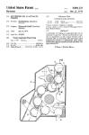
A sprocket feed mechanism 30 fits over and rotates
about the lower receiver rod 130. The main sprocket
assembly contains the sprocket 264, cartridge guide
spring, anti-rotation and sprocket release mechanisms
and maintains the alignment through engagement with
the main end cap and its sprocket-lower rod interface.
A cam tube assembly rotates about the lower tube and
drives the feed mechanism. It contains the drive ratchet
277 and a cycloidal cam slot path 270 which provides
for smooth continuous feeding throughout the entire
recoil cycle as the cam tube assembly is rotated by
longitudinal movement of the main drive pin of the
operating group as it moves in the cam slot path. This
feed mechanism has about one-fourth the number of
parts of conventional feed mechanisms such as the
M60 Machine Gun, for example.
The operating group 26 contains dual interchange-
able operating rods 244 and 246 attached to the bolt
carrier 236, by the main drive pin 168 which also actu-
ates the feed mechanism as it moves longitudinally in
the cam path 270 of the cam tube assembly 268. The
bolt carrier 236 contains the striker, cocking cam and
bolt locking/unlocking cam. The bolt is three lug in
design, with a striker mechanism and conventional
extraction, rammer and ejector systems. The drive
rods, 244, 246 reciprocate within the confines of the
receiver tubes 128, 130 where they have operational
interfaces with the gas systems and main drive springs
248, 250 while the bolt carrier receives positive guid-
ance through engagement with the exterior of the
upper rod and drive pin. The striker mechanism is
cocked during recoil and released during the last 0.10
inch of the bolt carrier motion in counterrecoil and
imparts a high velocity primer indent, i.e., strikes the
cartridge, at levels independent of slide velocity or
operational conditions.
The dust cover 22 has no function in the operating
group alignment as is typical of conventional receiver
elements. The ejection port and ejection port dust
cover assembly 96 is contained on the cover.
The buttstock assembly 16 houses a hydropneumatic
buffer and contains a folding buttplate, rear sling swivel
and storage space for cleaning equipment and spare
parts. The assembly attaches to the weapon through
engagement of the receiver tubes by a rotary cam lock
assembly. The buffer assembly contains a piston which
is acted upon at the limit of recoil by viscous dampen-
ing forces, air spring forces, and mechanical spring
forces in order to arrest the motion of the operating
parts. This low restitution system coupled with the
long, soft recoil of the weapon has resulted in greatly
5 reduced recoil as observed by gunnery personnel and
instrumental test results.
As previously mentioned, conventional single gas
system, high resituttion, high rate mechanisms inpart
eccentric loads of high magnitude upon the operating
10 components and anchor points of the receiver element
which result in high force transfer to the gunner (on the
order of 500 to 1200 peak lbs) resulting in reduced
controllability and reduced subcomponent and re-
ceiver life.
15 The weapon system of. the present invention has a
dual gas system which halves the load imparted to any
individual component and provides two separate and
independent power channels evenly spaced about the
gun barrel to achieve symmetrical thrust. This uniform
20 thrust shrouds the working elements of the mechanism
and mounting points thereby eliminating eccentric load
application to component subassemblies and exterior
mounting elements. The long/soft recoil cycle in com-
bination with the low restitution hydropneumatic buf-
25 fer assembly reduces the rate of fire and loads applied
to the gunner for improved controllability and recei-
ver/subcomponent part life. Illustratively, the inventive
system has achieved typical firing rates of less than 500
rounds per minute and less than 200 pounds of recoil
30 force through the buttstock. The simplistic conceptual
and modular design reduces manufacturing and life
cycle maintenance costs over conventional systems,
because lower internal working forces mean less stress
and longer service life of parts and less parts mean
35 lower costs of manufacture and maintenance.
BRIEF DESCRIPTION OF DRAWINGS
A more detailed and comprehensive description now
follows with reference to the drawings wherein:
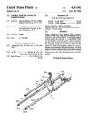
40 FIG. 1 is an elevational view of the weapon.
FIG. 2 is a plan view.
FIG. 3 is a rear end view.
FIG. 4 is a front end view.
FIGS. 5A and SB are exploded views taken in per-
45 spective, and
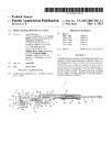
FIG. 6 is a sectional side elevational view.
DESCRIPTION OF PREFERRED EMBODIMENT
Referring now to the drawings there is shown in
50 FIGS. 1-4 a lightweight, air-cooled, gas operated,
linked belt/magazine fed machine gun 10 designed for
low rate automatic fire. This gun consists of barrel
assembly 12, foregrip assembly 14, buttstock assembly
16, aiming sight assembly 18, fire control assembly 20
55 and dust cover assembly 22. Internally, the gun 10
includes a receiver assembly 24, an operating group 26,
charger 28 and feed mechanism 30 as can be seen in
FIGS. 5 and 6.
As can be seen in FIGS. 1-4 the exposed parts of the
60 barrel assembly 12 include the barrel 32 which extends
both forwardly and rearwardly from a gas housing 34
having a front sight 36 integrally mounted on the top.
The forward end of the barrel 32 terminates in a flash
suppressor 37 of any convenient form known in the
65 prior art. The rear end of barrel 32 is hidden from view
by the front tube guide 38 of the receiver assembly 24
and heat shield 40 and door 42 of the foregrip assembly
14. Charger knob 44 is urged forwardly by charger
3,999,461
6
return spring 46 in cut-out portion 48 of door 42 which
is hingedly mounted at its lower edge 50 to heat shield
40.
Rearwardly of heat shield 40 is a bracket connection
or support in the form of main end cap 52 on top of
which aiming sight assembly 18 may conveniently be
mounted. This assembly has a sight base 54 on which is
pivotally mounted at 56 an elevation base 58 which is
adjustably positionable by elevation knob 60. An azi-
muth base 62, bearing the rear sight 64, is laterally
pivotable at 66 and is adjustable in azimuth by windage
knob 68.
Below the main end cap and removably attached to it
is the fire control assembly 20 having a hand grip 70,
grip guard cover 72, trigger 74, trigger guard 76, free
control housing 78 and safety latch 80. On the side of
the main end cap 52 is a barrel latch handle 82 for
fastening barrel extension 84 on the inner end of barrel
32 to the main end cap 52.
Rearwardly of main end cap 52 is the feed mecha-
nism housing 86 having a link ejection door 88 biased
by spring 90. Cartridge links are ejected through this
door after each of their associated rounds has been
sequentially chambered.
The dust cover 22 consists of a shell 92 sheet metal
construction and serves to protect the operating parts.
It contains a cartridge ejection port 94 and port dust
cover 96 biased by spring 98. This dust cover 22 typi-
cally would be part of the receiver in a prior art weapon
system but in the present embodiment it serves only as
a protective housing.
The buttstock assembly 16 comprises a buttstock 100
housing a hydropneumatic buffer and contains a fold-
ing buttplate 102 and a storage space for spare parts. A
cam lock handle 104 on the buttstock 100 is used to
assemble and disassemble it as a modular subassembly.
Attached to the buttstock 100 is a swivel 106 for an-
choring a sling 108.
As an option bipod leg assembly 110 may be added at
the time the gun barrel assembly 12 is connected to the
main end cap 52, and the gas housing 34 is positioned
against the gas cylinders 112, 114. This assembly has a
gun connector 116 which fits over the lower gas cylin-
der 114 as a means of attaching the assembly to the
gun. Extending from this connector is a bipod mount-
ing 118 from which legs 120,122 are hingedly mounted
at 124, 126. These legs may be placed in fully re-
tracted, up positions while carrying the weapon or in
the down position for prone firing.
A more detailed discussion and description of the
various parts will now be had with reference to the
exploded view in FIGS. 5A and SB. Here it can be seen
that receiver 24 consists of two elongated, substantially
parallel spaced-apart hollow cylindrical tubes 128,130
held in spaced relationship by front tube guide 38 and
main end cap 52. The front tube guide has a pair of
internally threaded connectors 132,134 which receive
pistons 136, 138, and ends 140, 142 of gas cylinders
112, 114 therein. The other ends 144, 146 are sealed
gas tight with gas rings 148,150 in bores (152 and 154
in FIG. 6) in gas housing 34 on barrel 32 where gas
ejecting a projectile also will move pistons 136, 138
rearwardly as will be explained hereinafter.
Barrel extension 84 fits within opening 156 in main
end cap 52. A barrel latch pin 158, handle 82 and
Belleville springs 160 rotate within aperture 162 in
main end cap 52 to Jock the extension 84 to the main
end cap 52. Recess 164 in latch pin 158 is flush with
opening 156 when extension 84 passes over it upon
insertion. However, rotation of pin 158 by latch handle
82 engages the pin 158 in a groove (166 in FIG. 6)
transverse of the underside of barrel extension 84 to
5 lock it in place.
Carrier tubes 128, 130 have longitudinal slots 166
therein to receive drive pin 168 in the operating group
26 as will be explained hereinafter. They also have
transverse outside grooves 170 to receive a cam lock
10 rod 174 of the buttstock assembly 16 in attaching butt-
stock 100 to the receiver 24.
Buttstock assembly 16 includes a buttplate assembly
176 having apertures 178, 180 for insertion over the
rear ends of tubes 128, 130. A vertical bore 182 com-
15 municates with these apertures and contains the cam
lock rod 174 which may be rotated by handle 104.
When rotated to locked position, a portion of rod 174
is received in notches 170, 172 to prevent withdrawal
of the end cap assembly from the receiver.
20 Rearward of buttplate assembly 176 is fastening
screw 184, buffer end cap 186, o-ring 188, buffer
spring 190, and buffer plunger 192. This plunger 192
passes through opening 194, in end cap assembly 176
to receive and dampen recoil forces from buffer stop
25 block 196 in operating group 26. Plunger scraper,
washer, fasteners and о-rings are provided at opening
194 to prevent escape of hydraulic fluid and gases and
to preclude entry of foregin material into buffer hous-
ing 176. Screw 184 also serves as a fastener for butt-
30 plate hinge 198 and swivel mount 200. Buttplate 102
pivots up on hinge 198 for prone firing as desired.
Retainer 202 fits into a cavity in buttstock 100 to house
cleaning tools and other small items.
The operating group 26 includes a bolt 204 having a
35 three-lug rotating locking head 206 that fits and locks
into barrel extension 84 during the firing cycle. Con-
tained within the bolt is an ejector 208 which is cap-
tured in an assembly with an ejector spring 210. An
extractor 212 is positioned diametrically opposite ejec-
40 tor 208 and is retained in position by a hook portion
214 over a flange 216 on the bolt. The extractor is
biased to extract spent cartridges with its lip 218 after
firing while the ejector 208 flips the cartridge from the
gun.
45 Contained within interior cylindrical recesses within
bolt 204 is the firing mechanism comprising firing pin
220, the firing pin cocking pin 222, firing pin spring
guide and follower 224 and firing pin spring 226. Firing
pin sear 228 retains the firing pin 220 in its rearward or
50 cocked position by dropping down under the influence
of extractor and sear spring 230 in front of shoulder
232 on the firing pin 220. Bolt cam pin 234 locks the
assembly and fits within a curved slot (hidden from
view) in bolt carrier 236. As this pin moves longitudi-
55 nally in the slot it rotates bolt 204 to lock and unlock
the bolt locking head 206 in barrel extension 84. While
this action is taking place, the firing pin cocking pin
222 rides in cocking slots 238, 240 on opposed sides of
carrier 236. During recoil the firing pin cocking pin
222 engages abutting shoulders 242 in slots 238, 240.
Bolt carrier 236 is fastened by drive pin 168 to elon-
gate force-transmitting means in the form of operating
rods 244, 246 which slide within tubes 128, 130 of
carrier 24 where they are urged forwardly by biasing
force means such as main drive springs 248,250. When
a cartridge is fired, gases move pistons 136, 138 rear-
ward with such force as to drive these rods 244, 246
rearward. There they are held rearwardly by sear 252
3,999,
7
which is pivotally mounted to main end cap 52 and
biased in such retention position by spring 254 so as to
engage notch 256 on lower rod 244. This notch is iden-
tical with notch 258 on upper rod 246, making the rods
identical and interchangeable. The bolt sear 237 is
pivotally mounted in the bolt carrier 236 and engages
bolt recess 239 during recoil and counterrecoil to keep
the bolt extended and to prevent premature rotation of
the bolt prior to the locking cycle.
Cartridges are fed into the gun on a linked belt from
a magazine, not shown, that clips onto the left hand
side of the feed housing 260 and also attaches onto a
detenting pin 262 on the bottom of hand grip 70.
Sprocket 264 receives the first cartridge and link. This
sprocket is rotatably mounted on lower tube 130 of the
carrier 24 and is confined in feed housing 260 which
also fits over tube 130. Feed tray cover 266 pivots from
the main end cap 52 for loading, and when closed and
latched provides guidance for incoming cartridges over
the sprocket 264. This sprocket is unique in that it has
3 rows of teeth, two narrow rows and a center wide
row. The fore and aft teeth provide cartridge control so
that the cartridge does not cant as it is rotated into full
feed position. The wider center row knifes into the void
between link/cartridge assemblies to provide control of
the link during the cartridge forward stripping process.
It also provides the forcing element which ejects the
spent link from the weapon during subsequent feeding
action.
Sprocket 264 is rotated during the recoiling cycle of
the operating group 26 during which drive pin 168
moves rearwardly in slot 166 of lower rod 130. A feed
cam tube 268 also fits over receiver tube 130 and has a
cycloidal slot 270 in it in which drive pin 168 also
travels. This rearward movement of pin 168 in slot 160
of tube 130 thus causes rotation of feed cam tube 268
in a clockwise direction looking forwardly from the
buttstock. A sprocket drive ratchet 272 urged by spring
274 fits into the front end 276 of tube 268 and engages
ratchet teeth (not shown) on the rear end of sprocket
264. Upon counterrecoil of the operating group 26, in
which drive pin 168 moves forward and drives feed
cam tube 268 in a counterclockwise direction, the
ratchet teeth 277 slip over the ratchet teeth (not
shown) on sprocket 264. During counter recoil the
sprocket is kept from reversing by a sprocket release
paul 278 which is loaded by spring 280 and mounted on
ratchet release pin 282. This pin is part of ratchet re-
lease 284 which, when manually retracted, disengages
the pawl 278, the feed tray cover 266 and ratchet drive
272. This frees the sprocket 264 for counterrotation
and accessibility for unloading or reloading.
A link port door 286 is pivotally mounted on feed
housing 260. These links are freed when their asso-
ciated cartridges are stripped by forward movement of
bolt 204. This bolt has a rammer 288 which moves the
cartridge up a guide ramp 290 on feed housing 260 and
into the chamber recess of barrel 32, during subsequent
recoil. It should be noted that when the cartridge is
positioned for stripping the diverging feed tray and
guide ramp 290 has caused an upward tipping of the
cartridge and link assembly in such a fashion that the
cartridge is on a direct line path to the chamber. This
differs from conventional feed systems where the car-
tridge is positioned parallel to the chamber centerline
and where the cartridge must move parallel in stripping
until such time as it has cleared the link assembly and
then migrate rapidly into the chamber area and again
5
10
15
20
25
30
35
40
45
50
55
60
65
,461
8
assume a parallel position before insertion into the
chamber. This sprocket, diverging feed tray and guide
ramp combination allows for positive prepositioning of
the cartridge such that the stripping process can be
accomplished in conjunction with direct line advance
of the cartridge to the chamber. This permits closer
positioning of feed components to the breech, provides
better cartridge feed control, reduces conventional
receiver length and malfunction potential.
The fire control assembly 20 consists of a housing 78,
hand grip 70, grip guard cover 72, trigger guard 76, and
trigger 74. This assembly is mounted on main end cap
52, but is offset to the right of the longitudinal center of
gravity to facilitate ease of handling and operation.
Housing 78 has a mounting plate 292, that fits into slots
294, in main end cap 52, when assembled. Safety latch
80, has a pin 296, on shank 298, that rides in a groove
(not shown) in main end cap 52, to lock the fire control
assembly 20, to the receiver 24 when the latch handle
300 is at fire position F, or safety position S as marked
on fire housing 78. Crank arm 302 of sear 252 is in-
serted into opening 304 of housing 78, where it is re-
ceived in groove 306 defined by jaws 308, 310 of trig-
ger 74. This trigger is pivoted at aperture 312 on pin
314 in apertures 316 in housing 78. A trigger spring
318 and spring retaining pin 320 fit into bore 322 in
housing 78. The outer end 324 engages trigger 74 and
moves rearward as the trigger is squeezed. However,
when latch handle 300 is depressed down to its safety
position S, movement of pin 320 is prevented and trig-
ger 74 cannot be depressed. This is because shaft 298
has a half-moon configuration and the path of the pin is
through the open space when the latch is in fire posi-
tion F and is blocked by the shaft when in safety posi-
tion. Shaft 298 has a flat configuration on its end 326
such that in safety position S, it abuts sear 252 to pre-
vent its downward movement from engagement with
operating rod 244.
The trigger guard 76 is pivotally mounted to legs 328
of fire control housing 78 with its outer end 330 in
friction contact with front end 332 of housing 78. Grip
guard cover 78 is pivotally mounted at 334 on handle
70 and its upper end 336 frictionally engages housing
legs 328. When use of the trigger guard 76 is not de-
sired, such as when the operator is wearing mittons, the
upper end 336 of grip guard cover 72 is pulled forward.
The trigger guard is pulled downwardly and rearwardly
to nest within the hand grip 70. Thereafter the guard
cover is rotated back into position and the gun is ready
for use without the trigger guard 76.
Reference is now made to FIG. 6, showing in sec-
tional view the various modules and subassemblies in
operating condition. Here is shown the receiver 24
consisting with its dual tubes 128, 130 held by front
tube guide 38 and main end cap 52. Barrel assembly 12
has its barrel extension 84 contained within the main
end cap 52 and the barrel gas housing 34 is positioned
over the gas cylinders 112, 114 which are threaded
onto connectors 132, 134 of front tube guide 38. Here
it can be seen that bores 152, 154 within housing 34
communicate between gun bore 388 and the gas cylin-
ders 112, 114 to supply gases from a spent cartridge to
pistons 136, 138 to propel the operating parts rear-
wardly.
The sight group 18 is mounted by screws 340 to main
end cap 52. The elevation base 58 rests on elevation
cam 342 which rotates about pivot 56 for desired eleva-
tion sighting.
3,999,461
9
10
Both the feed mechanism 30 and the operating group
26 are positioned over the receiver tubes 128, 130
before the dust cover 22 and buttstock assembly 16 are
added. The foregrip assembly 14 and fire control as-
sembly 20 may be added and removed in any sequence 5
since they do not depend upon installation or removal
of the parts in their assembly and removal. The foregrip
assembly 14 is installed by placing the lower portion
342 under the lower receiver tube 130 and springing
the top portion 344 over the top receiver tube 138. 10
Door 42 is spring loaded and pivots up to closed posi-
tion.
The operating group 26 is shown in its cocked or
rearward position. This is effected by pulling back the
charger knob 44 in FIG. 5A. This moves charger 15
bracket 356 against operating rod 256 and pushes it
rearwardly until sear 252 engages notch 256 of lower
operating rod 244. A round of ammunition 346 is posi-
tioned on sprocket 264, on guide ramp 290 and rear-
wardly of its firing position in chamber 348 in barrel 20
32. This round or cartridge 346 is still retained in its
belt by belt link 350. The open bolt position thus de-
scribed is customary in machine gun design to avoid
safety problems associated with having a cartridge
placed in a hot chamber for a period of time before 25
firing and having it fire (heated by previous firing) due
to premature cook-off caused by the high level of re-
tained heat in the breech.
The operating group 26 is held in its cocked or rear-
ward position against the resistance of drive springs 30
248, 250 by engagement of sear 252 in notch 256 of
lower operating rod 244 in lower receiver tube 130. In
cocked position, rammer 288 on bolt 204 is rearward
of cartridge 346, ready to ram the cartridge up ramp
290, free from its belt link 350 and into chamber 348. 35
In the operating group rearward position, as shown,
the bolt 204 and bolt carrier 236 are elongated. That is,
the carrier has moved further rearwardly than the bolt
and spring urged bolt sear 237 has engaged recess 239
in bolt 204. This is in order to maintain the bolt in a 40
forward extended position so that in firing the rammer
288 will load the cartridge into chamber 348 and the
three lugs 206 on the bolt 204 will align with the pass
through the three slots in the bolt locking head 206 in
barrel extension 84 before rotating and locking. (Rota- 45
tion is caused by bolt cam pin 234 riding in a slot 240
in bolt carrier 236).
When the bolt 204 has moved forward and become
locked with the barrel extension 84, the bolt sear 237 is
tripped by ramp 352 which is attached under the upper 50
carrier tube 128. This permits the bolt carriage 236 to
continue its forward movement until bolt 204 has been
locked, and thus release firing pin 220 to strike the
chambered cartridge 346. When shoulder 354 on bolt
carrier 236 moves forward and strikes sear 228, the 55
sear is freed from shoulder 232 of firing pin 220 which
is spring urged by spring 226 to move forward to strike
the cartridge.
As the bullet passes orifices 358,360, and bores 152,
154 in gas housing 34, gases propelling the spent bullet 60
cause pistons 136, 138 to ram operating rods 244, 246
rearwardly with more than enough force to move notch
256 in lower operating rod 244 rearwardly beyond sear
252. As the bolt carrier 236 moves back, bolt cam pin
234 rides a slot in the carrier to rotate the bolt 204 to 65
free it from barrel extension 84. Lip 218 on extractor
212 pulls out the spent cartridge case and ejector pin
208 flings it out of the gun.
As the bolt carrier 236 moves back, buffer stop block
196 in operating group 26 strikes buffer plunger 192 in
the buffer assembly in the buttstock group. This hydro-
pneumatic buffer assembly acts in three ways to bring
the high velocity operating group 26 from its rearward
movement to rest. A carefully measured charge of
hydraulic fluid and air in cylinder 362 of the end of cap
assembly 176 is compressed by the plunger piston 364
as the plunger 192 is thrust rearward. This fluid resists
rearward motion of the operating group 26 as it is me-
tered through piston orifices 366 in piston 364. Se-
condly, the gaseous air which is trapped in the buffer
housing cylinder 362 is compressed by the addition of
the volume of plunger shaft 192 that has been caused to
extend into the housing. This generates an increased
pressure acting as an area equivalent to the cross-sec-
tion of plunger 192. Thirdly, the plunger return spring
190 provides some mechanical resistance to this rear-
ward motion. These three buffering effects act in com-
bination with the main drive springs 248, 250 to slowly
arrest all rearward motion of the operating group 26.
This combined effect increases the time involved in
buffering over conventional systems by as much as
600%; reduces the associated load applied to the re-
ceiver and the gunner of gun mount by as much as
80-90%. The natural rate of fire of the mechanism has
also been reduced by approximately 35%. The com-
pressed piston return spring 190 has only sufficient
energy to return the plunger into its fully forward posi-
tion in time for the next buffering cycle.
On return, the forward movement of the operating
group 26 stops when sear 252 engages groove 256 in
lower operating rod 244 and the gun remains in cocked
position, ready for the squeeze of trigger 74 to start
operating again.
The gun is placed on safety when safety latch 80
(shown in FIG. SB) is depressed and shank 298 is ro-
tated. This rotates its half-moon configuration into the
path where the trigger spring retaining pin 320 is de-
pressed by trigger 74 and thus prevents movement of
the trigger. Shank 298 also has an end 326 with a pro-
jection that keeps sear 252 in groove 256 as a second or
double safety feature.
It should be noted that the dust cover assembly has
no operational function and may be removed at any
time without hindering weapon function. This makes it
possible to take high speed movies of the operating
parts to rapidly correct any developemental or manu-
facturing problem areas.
While the present invention has been described in
one illustrative embodiment, obviously other embodi-
ments will occur to one skilled in the art and it is to be
understood that any such deviations or modifications of
the embodiment just described are to be considered as
part of the present invention as defined by the claims.
What is claimed is:
1. A gas operated gun, comprising:
a gun barrel adapted to contain a gas under pressure
for propelling a projectile through said barrel,
a receiver having a pair of elongated, substantially
parallel hollow tubes,
said receiver further having bracket means con-
nected to each of said tubes for securing said tubes
fixedly in spaced-apart relationship and also for
securing said gun barrel between said tubes,
elongated force-transmitting means including operat-
ing rods longitudinally moveable within each of
said tubes,
3,999,461
11
12
gas cylinder means connected between said gun bar-
rel and said force-transmitting means, for applying
force generated from said gas under pressure to
said force-transmitting means,
a cartridge feeding mechanism rotatably mounted on 5
one of said tubes and a bolt carrier slidably
mounted on the other tube, and
a main drive pin inter-connecting said rods,
said tubes having slots therein along which said drive
pin rides in response to gas pressure applied to said io
operating rods,
said drive pin being operatively connected to said
cartridge feeding mechanism and to said bolt car-
rier.
2. A gas operated gun as set forth in claim 1 wherein 15
said cartridge feeding mechanism includes a feed cam
tube with an arcuate slot therein,
said feed cam tube being rotatably mounted on one
of said receiver tubes,
said drive pin extending into said arcuate slot and 20
thereby rotating said cam tube as said drive pin
moves along said slots in response to gas pressure
applied to said operating rods.
3. A gas operated gun as set forth in claim 2 wherein
said cartridge feeding mechanism includes a feed 25
sprocket rotatably mounted on one of said receiver
tubes,
and rotating means between said sprocket and said
feed cam tube for rotating said sprocket undirec-
tionally. 30
4. A gas operated gun as set forth in claim 3 including
release means for overriding said rotating means to
permit bidirectional rotation of said sprocket.
5. A gas operated gun as set forth in claim 3 including
a cartridge chamber in said barrel and wherein said 35
sprocket is contained within a feed housing having a
guide ramp therein for positioning cartridges while still
in links and on said sprocket in a direction angularly
oriented relative to said cartridge chamber in said bar-
rel. 40
6. A gas operated gun as set forth in claim 3 wherein
said sprocket has end rows of teeth to stabilize a car-
tridge thereon and an intermediate third row of teeth to
retain the stabilized cartridge link during forward strip-
ping of said cartridge therefrom. 45
7. A modular lightweight automatic weapon system
including:
a receiver having dual tubes spaced apart and con-
nected by a main end cap and a forward tube guide,
a barrel having a barrel extension held by said main 50
end cap and a gas housing connected to said front
tube guide,
said barrel having a bore through which a fired car-
tridge passes,
said gas housing having orifices interconnecting said 55
bore and said forward tube guide,
operating rods slidably mounted witin said tubes and
having a bolt carrier carried thereby,
said bolt carrier being operable when moved for-
wardly to move a cartridge into said barrel exten-
sion and maintain itself therebehind until said car-
tridge is fired,
said operating rods being actionable by gases in said
bore to move said bolt carrier rearwardly for ejec-
tion of spent cartridge cases, and
means indexing another cartridge in position for
movement into said barrel extension upon subse-
quent forward movement of said bolt carrier.
8. A modular lightweight automatic weapon system
as set forth in claim 7 wherein gas cylinders intercon-
nect said gas housing with said tubes and have pistons
therein, said pistons being operable by said gases to
move said operating rods and bolt carrier rearwardly
on said receiver tubes.
9. A modular lightweight automatic weapon system
as Set forth in claim 8 including counterrecoil springs in
said tubes to move said bolt carrier forwardly after
rearward motion of said bolt carrier has been termi-
nated.
10. A modular lightweight automatic weapon system
as set forth in claim 8 wherein a buttstock assembly is
fastened to the ends of said receiver tubes,
said buttstock assembly having a hydropneumatic
buffer to absorb recoil forces when said bolt carrier
moves rearwardly.
11. A gas operated gun, comprising:
a gun barrel adapted to contain a gas under pressure
for propelling a projectile through said barrel,
a receiver having a pair of elongated, substantially
parallel hollow tubes,
said receiver further having bracket means con-
nected to each of said tubes for securing said tubes
fixedly in spaced-apart relationship and also for
securing said gun barrel between said tubes,
elongated force-transmitting means within each of
said tubes,
gas cylinder means connected between said gun bar-
rel and said force-transmitting means, for applying
force generated from said gas under pressure to
said force-transmitting means,
a main drive connected to each of said force-trans-
mitting means for movement therewith,
a bolt carrier slidably mounted on one of said tubes
and movable with said main drive,
a cartridge feed mechanism rotatably mounted on
the other of said tubes,
said main drive being operatively connected to said
feed mechanism to cause rotation thereof upon
movement of said drive.
*****
60
65