/
Tags: weapons military affairs patent
Year: 1982


Text
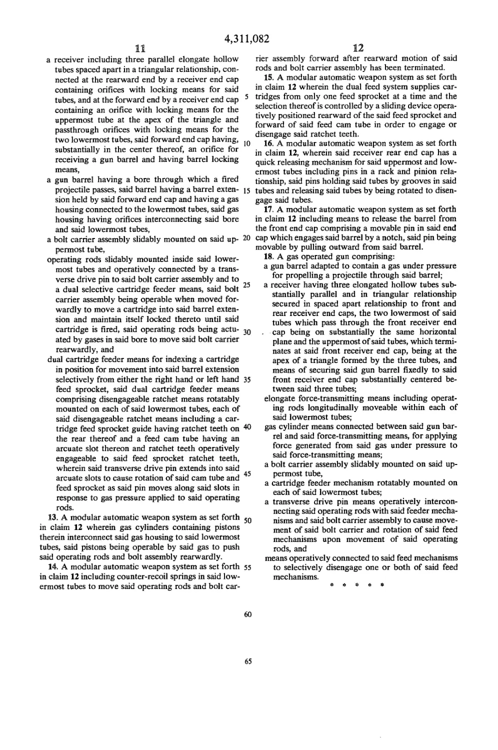
United States Patent n?]
Johnson et al.
[ii] 4,311,082
[45] Jan. 19, 1982
[54] GENERAL PURPOSE AUTOMATIC
WEAPON SYSTEM
[75] Inventors: Curtis D. Johnson, Wharton; Philip
L. Baker, Ogdensburg, both of N.J.
[73] Assignee: The United States of America as
represented by the Secretary of the
Array, Washington, D.C.
[21] Appl. No.: 255,582
[22] Filed: Apr. 20, 1981
Related U.S. Application Data
[63] Continuation of Ser. No. 48,105, Jun. 13, 1979, aban-
doned.
[51] Int. Cl.3..............................F41D 5/04
[52] U.S. Cl.................... 89/191 R; 89/33 CA;
89/33 SF; 89/185; 89/198; 89/199
[58] Field of Search............ 89/191 R, 198, 199,
89/185
[56] References Cited
U.S. PATENT DOCUMENTS
3,999,461 12/1976 Johnson et al.....89/191 R
4,022,105 5/1977 White.............. 89/185
4,191,089 3/1980 Zedrosser ......... 89/185
Primary Examiner—Stephen C. Bentley
Attorney, Agent, or Firm—Nathan Edelberg; Robert P.
Gibson; A. Victor Erkkila
[57] ABSTRACT
There is disclosed a gas operated, fully automatic
weapon system with a dual feed mechanism having a
long recoil, soft cycle operation. The automatic weapon
system consists of six groups or sub-assemblies. These
are the backplate (rear end cap/fire control assembly),
the dust cover unit, the dual selective rotary feed unit,
the operating group unit, the receiver unit, and the
barrel unit. These sub-assemblies combine to provide a
weapon characterized by lightness of weight, relatively
slight recoil force, relatively slow gunfire rate, excellent
manual control resulting in good burst fire accuracy in
hitting targets, and safety during operation and disas-
sembly.
18 Claims, 21 Drawing Figures
U.S. Patent Jan. 19, 1982
Sheet 1 of 10
4,311,082
U.S. Patent Jan. 19, 1982
Sheet 2 of 10
4,311,082
U.S. Patent Jan. 19, 1982 Sheet 3 of 10 4,311,082
FIG. 6
305
U.S. Patent Jan. 19, 1982
Sheet 4 of 10
4,311,082
U.S. Patent Jan. 19, 1982
Sheet 5 of 10
4,311,082
322
314
U.S. Patent Jan. 19, 1982
Sheet 6 of 10
4,311,082
U.S. Patent Jan. 19, 1982
Sheet 7 of 10
4,311,082
U.S. Patent Jan. 19, 1982
Sheet 8 of 10
4,311,082
U.S. Patent Jan. 19, 1982
Sheet 9 of 10
4,311,082
U.S. Patent Jan. 19, 1982
Sheet 10 of 10
4,311,082
4,311,082
1
GENERAL PURPOSE AUTOMATIC WEAPON
SYSTEM
GOVERNMENT RIGHTS
The invention described herein may be manufactured
and/or used by or for the Government for governmen-
tal purposes without the payment to me of any royalty
thereon.
CROSS REFERENCE TO RELATED
APPLICATIONS
This application is a continuation of application Ser.
No. 048,105, filed June 13, 1979, abandoned.
BACKGROUND OF THE INVENTION
In recent years great strides have been made in im-
proving automatic gas operated weapon systems of the
machine gun genre. New types of ammunition feed
mechanisms based on rotary sprocket systems such as
disclosed in Johnson et al., U.S. Pat. Nos. 3,999,461 and
4,061,074 have made it possible to significantly decrease
the number of parts in and weight of portable machine
guns and simplify the replacement of worn out or bro-
ken parts, as well as the manufacture of such weapons.
Such portable machine guns as disclosed in the Johnson
et al., patents have various advantages, such as less
recoil displacement with greater control of aim and
increased accuracy. The novel design and operation of
these machine guns, while manifesting significant ad-
vantages, are not completely adaptable to situations
where there is a need for a weapon capable of shooting
high caliber ammunition, e.g., 50 caliber or higher, from
vehicles, such as jeeps, or airplanes, or from tripod
mounts. In addition, since the prior weapons contain
only one feed mechanism they cannot provide the capa-
bility of utilizing different types of ammunition of a
specific caliber without switching ammunition belts and
possibly gas operating units. Dual feed units which are
known are cumbersome to work with, since they re-
quire complete disengagement and displacement of one
feed mechanism to enable use of the second feed mecha-
nism and, in addition, have relatively primitive gas op-
erating units. The weapon system of this invention pro-
vides a dual feed mechanism, as well as other mecha-
nisms which show advantageous properties and capabil-
ities over known weapons, and which will be discussed
hereinafter.
SUMMARY OF THE INVENTION
The present invention relates to a gas operated, fully
automatic weapon system with a dual feed mechanism
having a long recoil, soft cycle of operation. This results
in a rate of fire of about 500 rounds per minute, which
makes possible good controlability and increased useful
life of the weapon. The weapon system of the present
invention has relatively few parts, about 160, and is
composed of six units or sub-assemblies. The modular
design reduces maintenance time and life cycle logistics
costs while lower internal working forces mean lower
costs of manufacture, materials and maintenance re-
quirements.
The weapon system of the present invention has a
dual gas system which halves the load imparted to any
individual component and provides two separate and
independent power channels evenly spaced about the
gun barrel to achieve symmetrical thrust. This uniform
thrust shrouds the working elements of the mechanism
5
10
15
20
25
30
35
40
45
50
55
60
65
2
and mounting points, thereby eliminating eccentric load
application to component sub-assemblies and exterior
mounting elements. The long/soft recoil cycle in com-
bination with the low restitution hydropneumatic buffer
assemblies reduces the rate of fire and loads applied to
the gun and gun mounting system, resulting in im-
proved controllability, hit probabilities, and receiver/-
component part life. The inventive system achieves, for
example, typical firing rates of less than 500 rounds per
minute with less than 1,000 pounds of recoil force with
50 caliber ammunition through the gun system mount-
ing points. In addition, the weapon system of this inven-
tion is characterized by containing three tubes between
the rear end cap and front end cap receiver units. These
tubes which are parallel in spaced apart triangular rela-
tionship give structure to the weapon. The lower two
tubes which support the dual feed assembly enable a
selective feed means to be utilized and enable the opera-
tor to easily switch from the left hand feed to the right
hand feed and vice versa, by pushing or pulling a cross-
over bar mechanism and without the need to download
the weapon of ammunition.
Briefly, the automatic weapon system of the present
invention consists of six groups or sub-assemblies. These
are the backplate (read end cap/fire control assembly),
the dust cover unit, the dual selective rotary feed unit,
the operating group unit, the receiver unit, and the
barrel unit. These sub-assemblies, as well as other mod-
ular and unitary sub-assemblies can be separately re-
moved from the weapon as individual modules or units
and replaced with other corresponding sub-assemblies.
This provides for immediate unit level maintenance
with minimum weapon down-time and, in addition,
provides a means to readily adapt the weapon to ammu-
nitions of different calibers. These sub-assemblies com-
bine to provide a weapon characterized by lightness of
weight, relatively slight recoil force, relatively slow
gun fire rate, excellent manual control resulting in good
burst fire accuracy in hitting targets, and safety during
operation and disassembly.
DESCRIPTION OF THE DRAWINGS
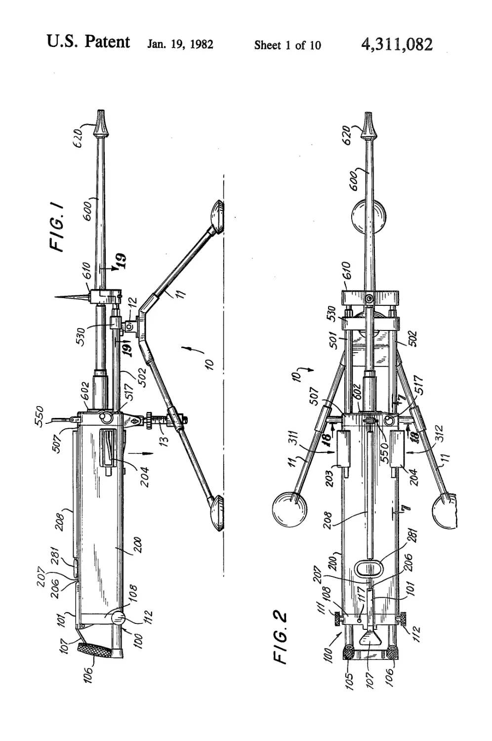
FIG. 1 is a side view of the fully assembled weapon.
FIG. 2 is a top plan view of the weapon.
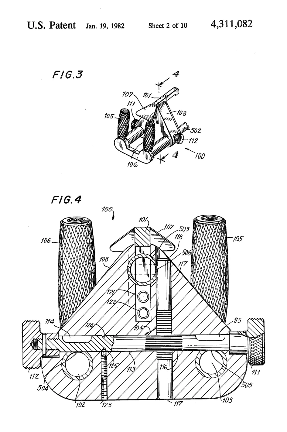
FIG. 3 is a perspective of the back plate group.
FIG. 4 is section 4—4 of the back plate group of FIG.
3.
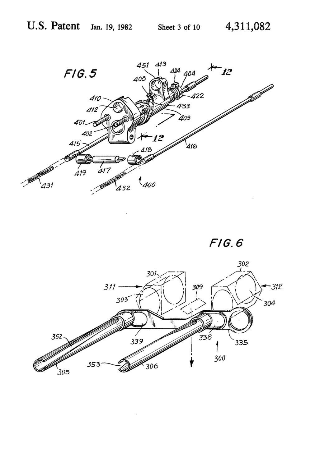
FIG. 5 is a perspective of the operating group unit.
FIG. 6 is a perspective of the dual selective rotary
feed assembly.
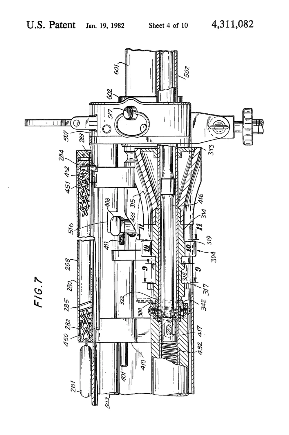
FIG. 7 is section 7—7 of FIG. 2.
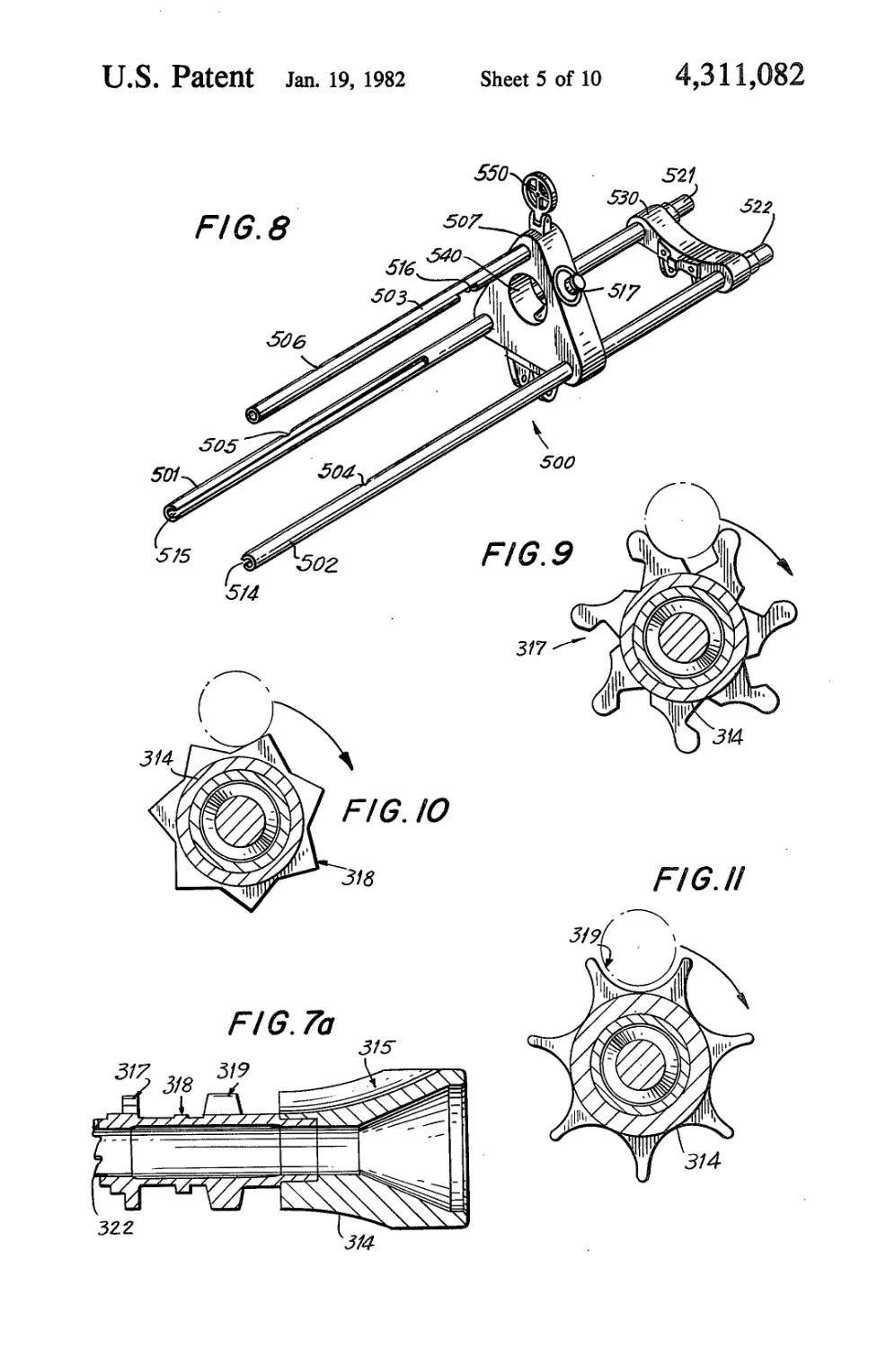
FIG. 7a is a sectional view of a feed sprocket assem-
bly.
FIG. 8 is the receiver unit.
FIG. 9 is section 9—9 of FIG. 7.
FIG. 10 is section 10—10 of FIG. 7.
FIG. 11 is section 11—11 of FIG. 7.
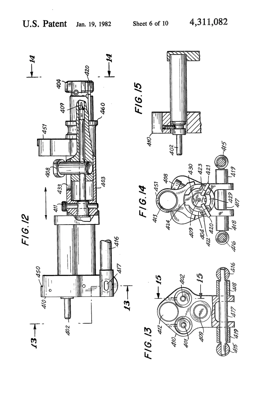
FIG. 12 is section 12—12 of FIG. 5.
FIG. 13 is section 13—13 of FIG. 12.
FIG. 14 is section 14—14 of FIG. 12.
FIG. 15 is section 15—15 of FIG. 13.
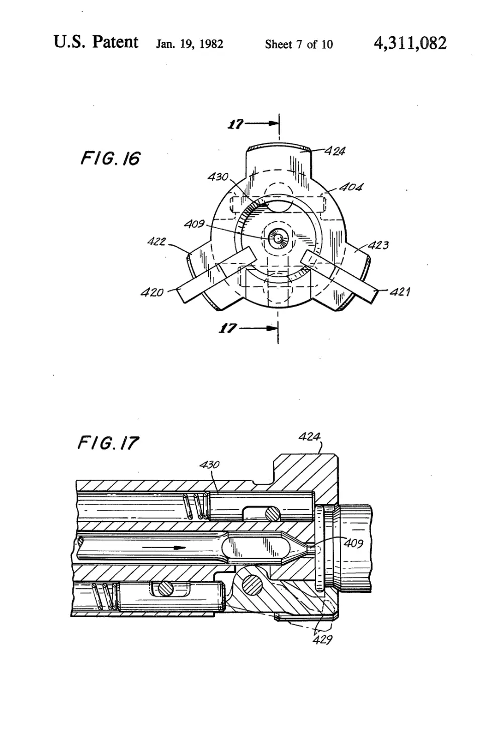
FIG. 16 is enlarged front elevation of the operating
group.
FIG. 17 is section 17—17 of FIG. 16.
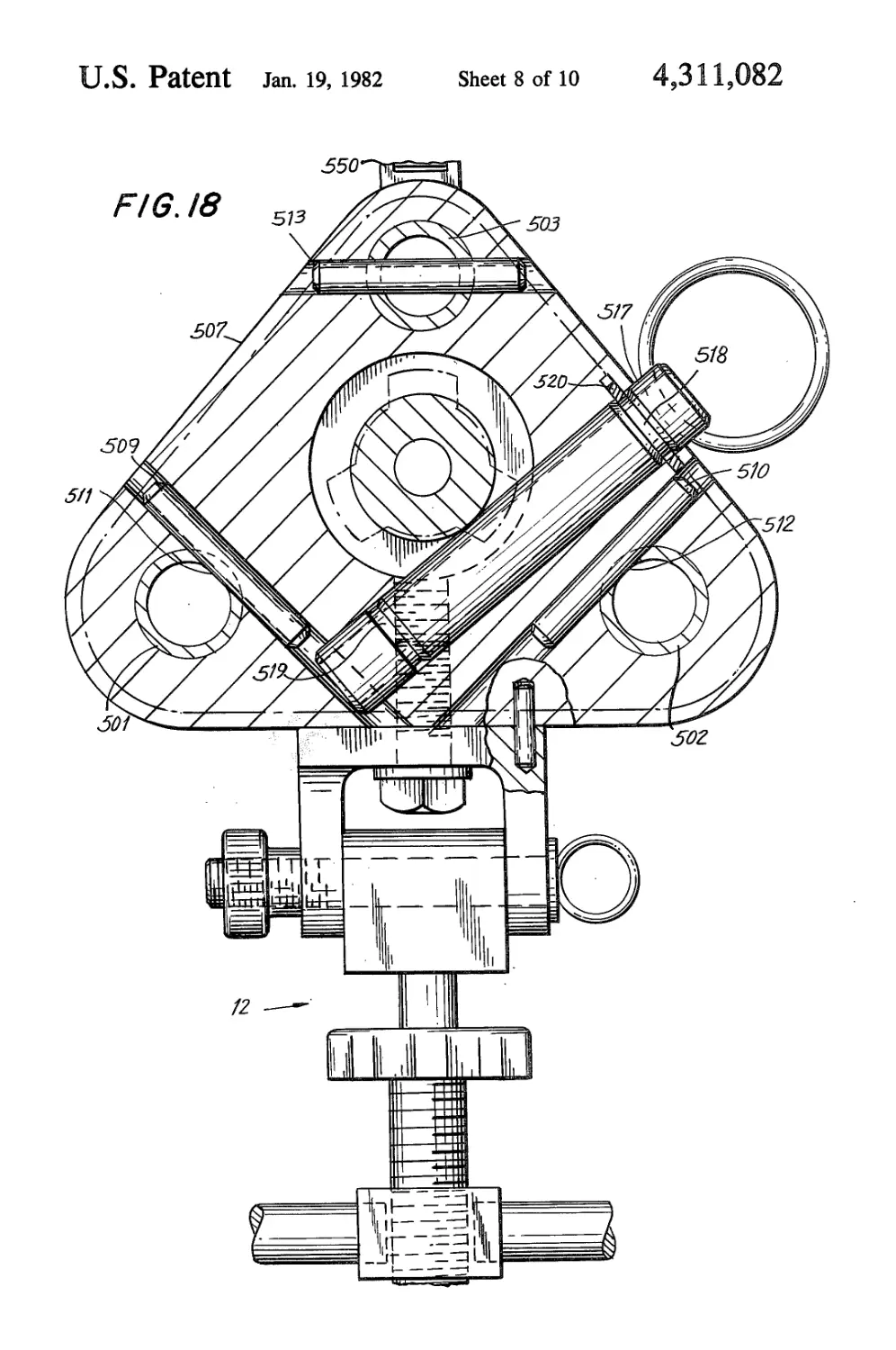
FIG. 18 is section 18—18 of FIG. 2.
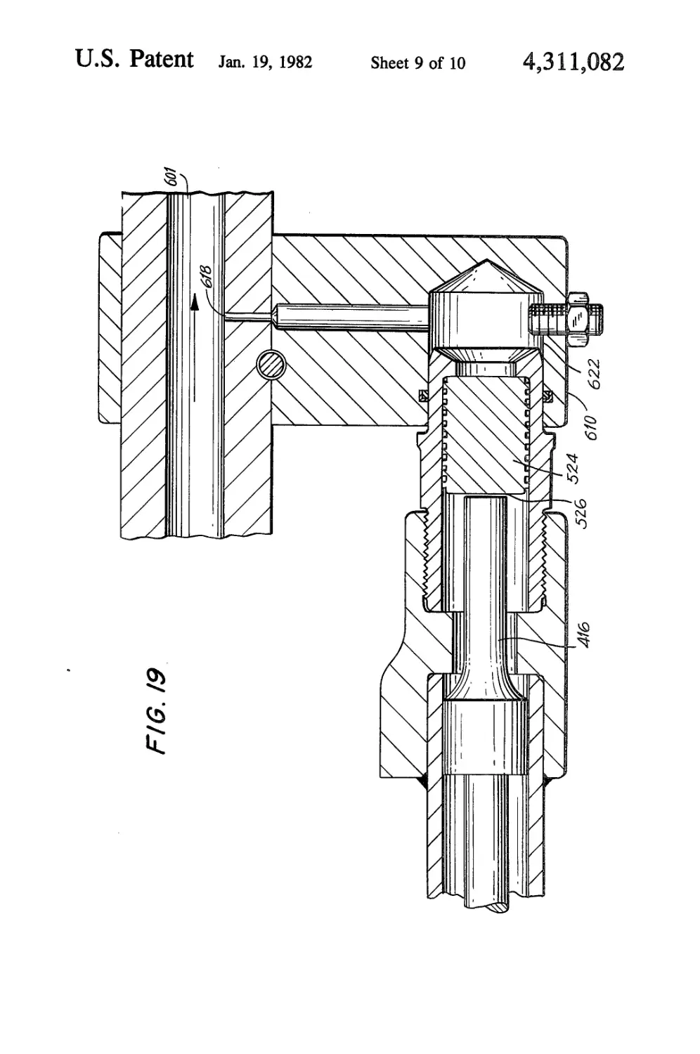
FIG. 19 is section 19—19 of FIG. 1.
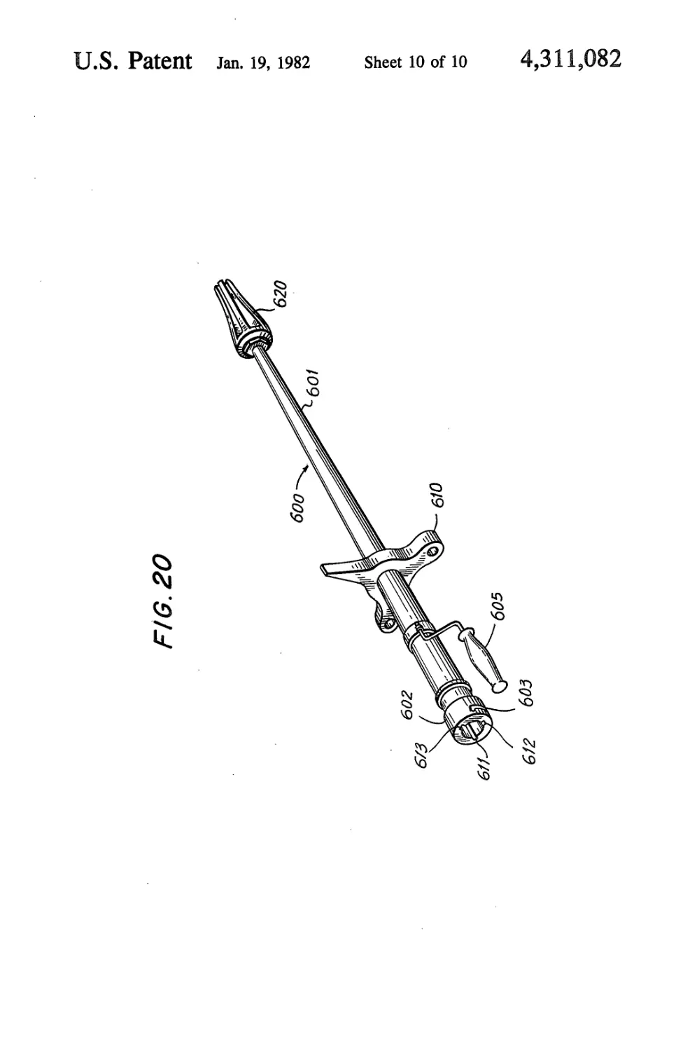
FIG. 20 is a perspective of the barrel group.
4,311,082
3
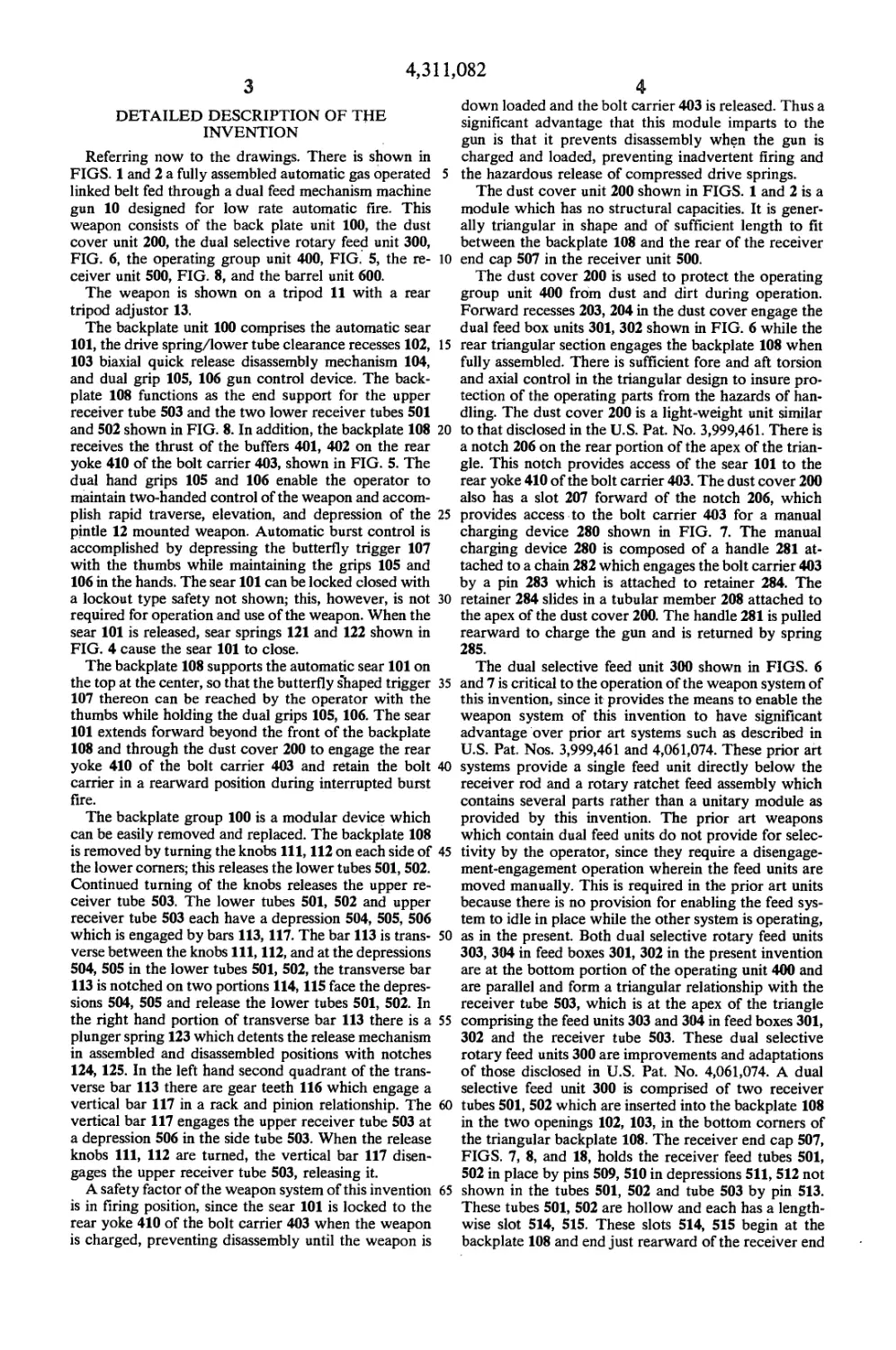
DETAILED DESCRIPTION OF THE
INVENTION
Referring now to the drawings. There is shown in
FIGS. 1 and 2 a fully assembled automatic gas operated
linked belt fed through a dual feed mechanism machine
gun 10 designed for low rate automatic fire. This
weapon consists of the back plate unit 100, the dust
cover unit 200, the dual selective rotary feed unit 300,
FIG. 6, the operating group unit 400, FIG. 5, the re-
ceiver unit 500, FIG. 8, and the barrel unit 600.
The weapon is shown on a tripod 11 with a rear
tripod adjustor 13.
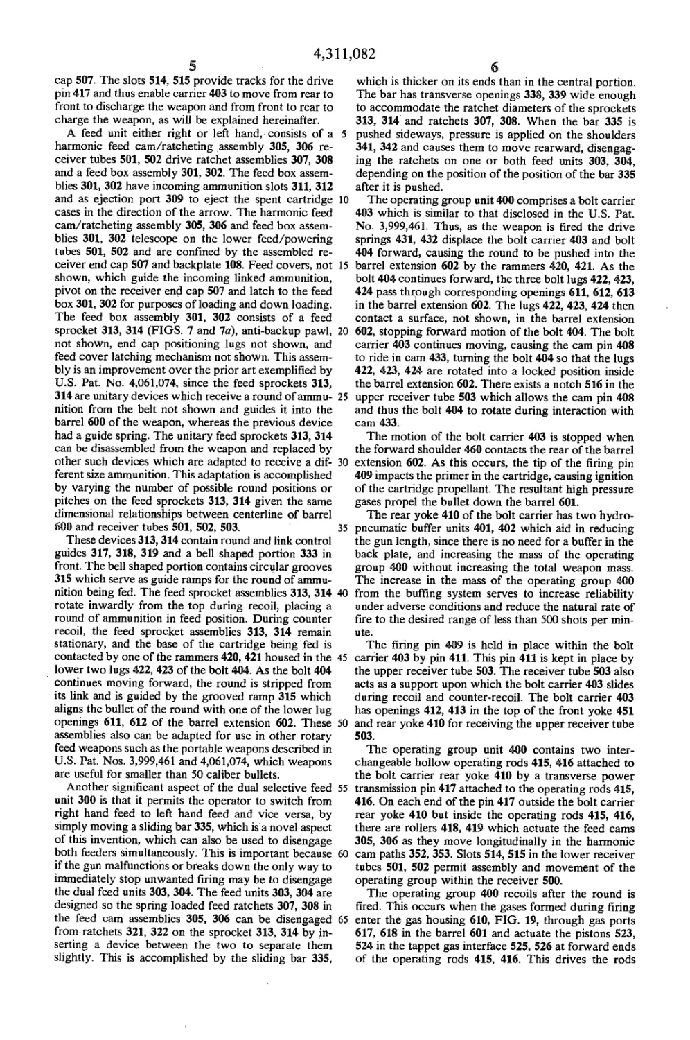
The backplate unit 100 comprises the automatic sear
101, the drive spring/lower tube clearance recesses 102,
103 biaxial quick release disassembly mechanism 104,
and dual grip 105, 106 gun control device. The back-
plate 108 functions as the end support for the upper
receiver tube 503 and the two lower receiver tubes 501
and 502 shown in FIG. 8. In addition, the backplate 108
receives the thrust of the buffers 401, 402 on the rear
yoke 410 of the bolt carrier 403, shown in FIG. 5. The
dual hand grips 105 and 106 enable the operator to
maintain two-handed control of the weapon and accom-
plish rapid traverse, elevation, and depression of the
pintle 12 mounted weapon. Automatic burst control is
accomplished by depressing the butterfly trigger 107
with the thumbs while maintaining the grips 105 and
106 in the hands. The sear 101 can be locked closed with
a lockout type safety not shown; this, however, is not
required for operation and use of the weapon. When the
sear 101 is released, sear springs 121 and 122 shown in
FIG. 4 cause the sear 101 to close.
The backplate 108 supports the automatic sear 101 on
the top at the center, so that the butterfly shaped trigger
107 thereon can be reached by the operator with the
thumbs while holding the dual grips 105, 106. The sear
101 extends forward beyond the front of the backplate
108 and through the dust cover 200 to engage the rear
yoke 410 of the bolt carrier 403 and retain the bolt
carrier in a rearward position during interrupted burst
fire.
The backplate group 100 is a modular device which
can be easily removed and replaced. The backplate 108
is removed by turning the knobs 111, 112 on each side of
the lower comers; this releases the lower tubes 501,502.
Continued turning of the knobs releases the upper re-
ceiver tube 503. The lower tubes 501, 502 and upper
receiver tube 503 each have a depression 504, 505, 506
which is engaged by bars 113,117. The bar 113 is trans-
verse between the knobs 111, 112, and at the depressions
504, 505 in the lower tubes 501, 502, the transverse bar
113 is notched on two portions 114,115 face the depres-
sions 504, 505 and release the lower tubes 501, 502. In
the right hand portion of transverse bar 113 there is a
plunger spring 123 which detents the release mechanism
in assembled and disassembled positions with notches
124, 125. In the left hand second quadrant of the trans-
verse bar 113 there are gear teeth 116 which engage a
vertical bar 117 in a rack and pinion relationship. The
vertical bar 117 engages the upper receiver tube 503 at
a depression 506 in the side tube 503. When the release
knobs 111, 112 are turned, the vertical bar 117 disen-
gages the upper receiver tube 503, releasing it.
A safety factor of the weapon system of this invention
is in firing position, since the sear 101 is locked to the
rear yoke 410 of the bolt carrier 403 when the weapon
is charged, preventing disassembly until the weapon is
5
10
15
20
25
30
35
40
45
50
55
60
65
4
down loaded and the bolt carrier 403 is released. Thus a
significant advantage that this module imparts to the
gun is that it prevents disassembly when the gun is
charged and loaded, preventing inadvertent firing and
the hazardous release of compressed drive springs.
The dust cover unit 200 shown in FIGS. 1 and 2 is a
module which has no structural capacities. It is gener-
ally triangular in shape and of sufficient length to fit
between the backplate 108 and the rear of the receiver
end cap 507 in the receiver unit 500.
The dust cover 200 is used to protect the operating
group unit 400 from dust and dirt during operation.
Forward recesses 203, 204 in the dust cover engage the
dual feed box units 301, 302 shown in FIG. 6 while the
rear triangular section engages the backplate 108 when
fully assembled. There is sufficient fore and aft torsion
and axial control in the triangular design to insure pro-
tection of the operating parts from the hazards of han-
dling. The dust cover 200 is a light-weight unit similar
to that disclosed in the U.S. Pat. No. 3,999,461. There is
a notch 206 on the rear portion of the apex of the trian-
gle. This notch provides access of the sear 101 to the
rear yoke 410 of the bolt carrier 403. The dust cover 200
also has a slot 207 forward of the notch 206, which
provides access to the bolt carrier 403 for a manual
charging device 280 shown in FIG. 7. The manual
charging device 280 is composed of a handle 281 at-
tached to a chain 282 which engages the bolt carrier 403
by a pin 283 which is attached to retainer 284. The
retainer 284 slides in a tubular member 208 attached to
the apex of the dust cover 200. The handle 281 is pulled
rearward to charge the gun and is returned by spring
285.
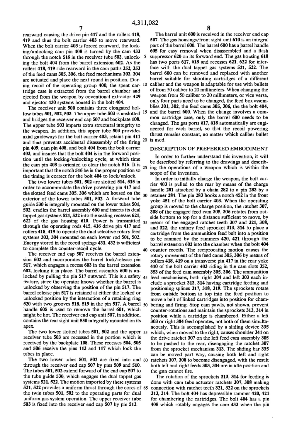
The dual selective feed unit 300 shown in FIGS. 6
and 7 is critical to the operation of the weapon system of
this invention, since it provides the means to enable the
weapon system of this invention to have significant
advantage over prior art systems such as described in
U.S. Pat. Nos. 3,999,461 and 4,061,074. These prior art
systems provide a single feed unit directly below the
receiver rod and a rotary ratchet feed assembly which
contains several parts rather than a unitary module as
provided by this invention. The prior art weapons
which contain dual feed units do not provide for selec-
tivity by the operator, since they require a disengage-
ment-engagement operation wherein the feed units are
moved manually. This is required in the prior art units
because there is no provision for enabling the feed sys-
tem to idle in place while the other system is operating,
as in the present. Both dual selective rotary feed units
303, 304 in feed boxes 301, 302 in the present invention
are at the bottom portion of the operating unit 400 and
are parallel and form a triangular relationship with the
receiver tube 503, which is at the apex of the triangle
comprising the feed units 303 and 304 in feed boxes 301,
302 and the receiver tube 503. These dual selective
rotary feed units 300 are improvements and adaptations
of those disclosed in U.S. Pat. No. 4,061,074. A dual
selective feed unit 300 is comprised of two receiver
tubes 501, 502 which are inserted into the backplate 108
in the two openings 102, 103, in the bottom comers of
the triangular backplate 108. The receiver end cap 507,
FIGS. 7, 8, and 18, holds the receiver feed tubes 501,
502 in place by pins 509, 510 in depressions 511, 512 not
shown in the tubes 501, 502 and tube 503 by pin 513.
These tubes 501, 502 are hollow and each has a length-
wise slot 514, 515. These slots 514, 515 begin at the
backplate 108 and end just rearward of the receiver end
4,311,082
5
cap 507. The slots 514, 515 provide tracks for the drive
pin 417 and thus enable carrier 403 to move from rear to
front to discharge the weapon and from front to rear to
charge the weapon, as will be explained hereinafter.
A feed unit either right or left hand, consists of a
harmonic feed cam/ratcheting assembly 305, 306 re-
ceiver tubes 501, 502 drive ratchet assemblies 307, 308
and a feed box assembly 301, 302. The feed box assem-
blies 301, 302 have incoming ammunition slots 311, 312
and as ejection port 309 to eject the spent cartridge
cases in the direction of the arrow. The harmonic feed
cam/ratcheting assembly 305, 306 and feed box assem-
blies 301, 302 telescope on the lower feed/powering
tubes 501, 502 and are confined by the assembled re-
ceiver end cap 507 and backplate 108. Feed covers, not
shown, which guide the incoming linked ammunition,
pivot on the receiver end cap 507 and latch to the feed
box 301, 302 for purposes of loading and down loading.
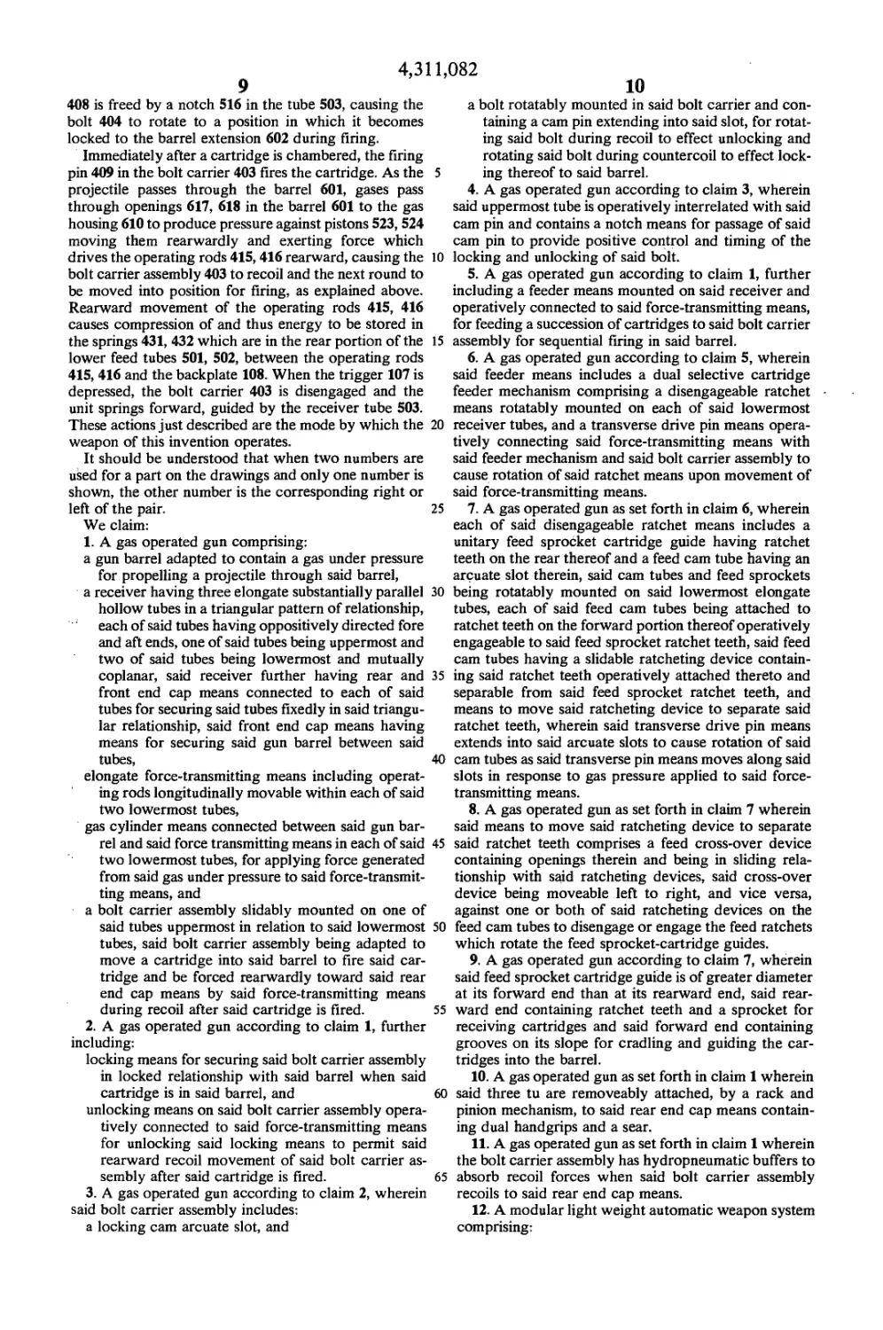
The feed box assembly 301, 302 consists of a feed
sprocket 313, 314 (FIGS. 7 and 7a), anti-backup pawl,
not shown, end cap positioning lugs not shown, and
feed cover latching mechanism not shown. This assem-
bly is an improvement over the prior art exemplified by
U.S. Pat. No. 4,061,074, since the feed sprockets 313,
314 are unitary devices which receive a round of ammu-
nition from the belt not shown and guides it into the
barrel 600 of the weapon, whereas the previous device
had a guide spring. The unitary feed sprockets 313, 314
can be disassembled from the weapon and replaced by
other such devices which are adapted to receive a dif-
ferent size ammunition. This adaptation is accomplished
by varying the number of possible round positions or
pitches on the feed sprockets 313, 314 given the same
dimensional relationships between centerline of barrel
600 and receiver tubes 501, 502, 503.
These devices 313, 314 contain round and link control
guides 317, 318, 319 and a bell shaped portion 333 in
front. The bell shaped portion contains circular grooves
315 which serve as guide ramps for the round of ammu-
nition being fed. The feed sprocket assemblies 313, 314
rotate inwardly from the top during recoil, placing a
round of ammunition in feed position. During counter
recoil, the feed sprocket assemblies 313, 314 remain
stationary, and the base of the cartridge being fed is
contacted by one of the rammers 420, 421 housed in the
lower two lugs 422, 423 of the bolt 404. As the bolt 404
continues moving forward, the round is stripped from
its link and is guided by the grooved ramp 315 which
aligns the bullet of the round with one of the lower lug
openings 611, 612 of the barrel extension 602. These
assemblies also can be adapted for use in other rotary
feed weapons such as the portable weapons described in
U.S. Pat. Nos. 3,999,461 and 4,061,074, which weapons
are useful for smaller than 50 caliber bullets.
Another significant aspect of the dual selective feed
unit 300 is that it permits the operator to switch from
right hand feed to left hand feed and vice versa, by
simply moving a sliding bar 335, which is a novel aspect
of this invention, which can also be used to disengage
both feeders simultaneously. This is important because
if the gun malfunctions or breaks down the only way to
immediately stop unwanted firing may be to disengage
the dual feed units 303, 304. The feed units 303, 304 are
designed so the spring loaded feed ratchets 307, 308 in
the feed cam assemblies 305, 306 can be disengaged
from ratchets 321, 322 on the sprocket 313, 314 by in-
serting a device between the two to separate them
slightly. This is accomplished by the sliding bar 335,
5
10
15
20
25
30
35
40
45
50
55
60
65
6
which is thicker on its ends than in the central portion.
The bar has transverse openings 338, 339 wide enough
to accommodate the ratchet diameters of the sprockets
313, 314 and ratchets 307, 308. When the bar 335 is
pushed sideways, pressure is applied on the shoulders
341, 342 and causes them to move rearward, disengag-
ing the ratchets on one or both feed units 303, 304,
depending on the position of the position of the bar 335
after it is pushed.
The operating group unit 400 comprises a bolt carrier
403 which is similar to that disclosed in the U.S. Pat.
No. 3,999,461. Thus, as the weapon is fired the drive
springs 431, 432 displace the bolt carrier 403 and bolt
404 forward, causing the round to be pushed into the
barrel extension 602 by the rammers 420, 421. As the
bolt 404 continues forward, the three bolt lugs 422, 423,
424 pass through corresponding openings 611, 612, 613
in the barrel extension 602. The lugs 422, 423, 424 then
contact a surface, not shown, in the barrel extension
602, stopping forward motion of the bolt 404. The bolt
carrier 403 continues moving, causing the cam pin 408
to ride in cam 433, turning the bolt 404 so that the lugs
422, 423, 424 are rotated into a locked position inside
the barrel extension 602. There exists a notch 516 in the
upper receiver tube 503 which allows the cam pin 408
and thus the bolt 404 to rotate during interaction with
cam 433.
The motion of the bolt carrier 403 is stopped when
the forward shoulder 460 contacts the rear of the barrel
extension 602. As this occurs, the tip of the firing pin
409 impacts the primer in the cartridge, causing ignition
of the cartridge propellant. The resultant high pressure
gases propel the bullet down the barrel 601.
The rear yoke 410 of the bolt carrier has two hydro-
pneumatic buffer units 401, 402 which aid in reducing
the gun length, since there is no need for a buffer in the
back plate, and increasing the mass of the operating
group 400 without increasing the total weapon mass.
The increase in the mass of the operating group 400
from the buffing system serves to increase reliability
under adverse conditions and reduce the natural rate of
fire to the desired range of less than 500 shots per min-
ute.
The firing pin 409 is held in place within the bolt
carrier 403 by pin 411. This pin 411 is kept in place by
the upper receiver tube 503. The receiver tube 503 also
acts as a support upon which the bolt carrier 403 slides
during recoil and counter-recoil. The bolt carrier 403
has openings 412, 413 in the top of the front yoke 451
and rear yoke 410 for receiving the upper receiver tube
503.
The operating group unit 400 contains two inter-
changeable hollow operating rods 415, 416 attached to
the bolt carrier rear yoke 410 by a transverse power
transmission pin 417 attached to the operating rods 415,
416. On each end of the pin 417 outside the bolt carrier
rear yoke 410 but inside the operating rods 415, 416,
there are rollers 418, 419 which actuate the feed cams
305, 306 as they move longitudinally in the harmonic
cam paths 352, 353. Slots 514, 515 in the lower receiver
tubes 501, 502 permit assembly and movement of the
operating group within the receiver 500.
The operating group 400 recoils after the round is
fired. This occurs when the gases formed during firing
enter the gas housing 610, FIG. 19, through gas ports
617, 618 in the barrel 601 and actuate the pistons 523,
524 in the tappet gas interface 525, 526 at forward ends
of the operating rods 415, 416. This drives the rods
4,311,082
8
7
rearward causing the drive pin 417 and the rollers 418,
419 and thus the bolt carrier 403 to move rearward.
When the bolt carrier 403 is forced rearward, the lock-
ing/unlocking cam pin 408 is turned by the cam 433
through the notch 516 in the receiver tube 503, unlock- 5
ing the bolt 404 from the barrel extension 602. As the
rollers 418, 419 ride rearward in the cam paths 352, 353
of the feed cams 305, 306, the feed mechanisms 303, 304
are actuated and place the next round in position. Dur-
ing recoil of the operating group 400, the spent car- 10
tridge case is extracted from the barrel chamber and
ejected from the weapon by coventional extractor 429
and ejector 430 systems housed in the bolt 404.
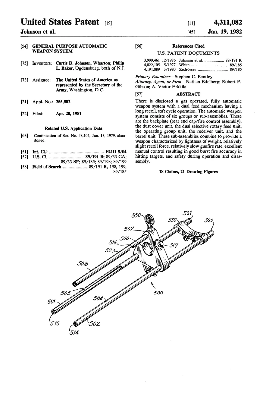
The receiver unit 500 contains three elongated hol-
low tubes 501, 502, 503. The upper tube 503 is unslotted
and bridges the receiver end cap 507 and backplate 108.
The upper tube 503 imparts extra structural integrity to
the weapon. In addition, this upper tube 503 provides
axial guideways for the bolt carrier 403, retains pin 411
and thus prevents accidental disassembly of the firing
pin 409, cam pin 408, and bolt 404 from the bolt carrier
403, and insures that the bolt 404 is in the forward posi-
tion until the locking/unlocking cycle, at which time
the cam pin 408 is oriented to clear the notch 516. It is 25
important that the notch 516 be in the proper position so
the timing is correct for the bolt 404 to lock/unlock.
The two lower tubes 501, 502 are slotted 514, 515 in
order to accommodate the drive powering pin 417 and
the slotted feed cams 305, 306 which are housed on the
exterior of the lower tubes 501, 502. A forward tube
guide 530 is integrally mounted on the lower tubes 501,
502, cradles the barrel assembly 600 and inserts its dual
tappet gas systems 521, 522 into the sealing recesses 621,
622 of the gas housing 610. Power is transmitted 35
through the operating rods 415, 416 drive pin 417 and
rollers 418, 419 to operate the dual selective rotary feed
systems 303, 304 mounted on each lower rod 501, 502.
Energy stored in the recoil springs 431, 432 is sufficient
to complete the counter-recoil cycle. 40
The receiver end cap 507 receives the barrel exten-
sion 602 and incorporates the barrel lock/release pin
517, which engages a recess 603 in the barrel extension
602, locking it in place. The barrel assembly 600 is un-
locked by pulling the pin 517 outward. This is a safety 45
feature, since the operator knows whether the barrel is
unlocked by observing the position of the pin 517. The
barrel release pin 517 is retained at either the locked or
unlocked position by the interaction of a retaining ring
520 with two grooves 518, 519 in the pin 517. A barrel 50
handle 605 is used to remove the barrel 601, which
might be hot. The receiver end cap unit 507, in addition,
contains the rear sight unit 550 integrally mounted on its
apex.
The two lower slotted tubes 501, 502 and the upper 55
receiver tube 503 are recessed in the portion which is
received by the backplate 108. These recesses 504, 505
and 506 receive the pins 113 and 117 which lock the
tubes in place.
The two lower tubes 501, 502 are fixed into and
through the receiver end cap 507 by pins 509 and 510.
The tubes 501, 502 extend forward of the end cap 507 to
the tube guide 530, which engages the dual tappet gas
systems 521, 522. The motion imported by these systems
521, 522 provides a uniform thrust through the cores of
the twin tubes 501, 502 to the operating parts for dual
uniform gas system operation. The upper receiver tube
503 is fixed into the receiver end cap 507 by pin 513.
The barrel unit 600 is received in the receiver end cap
507. The gas housings/front sight unit 610 is an integral
part of the barrel 600. The barrel 600 has a barrel handle
605 for easy removal when disassembled and a flash
suppressor 620 on its forward end. The gas housing 610
has two ports 617, 618 and recesses 621, 622 for inter-
face with the dual tappet gas systems 521, 522. The
barrel 600 can be removed and replaced with another
barrel suitable for shooting cartridges of a different
caliber and the weapon is adaptable for use with bullets
of from 50 caliber to 20 millimeters. When changing the
weapon from 50 caliber to 20 millimeters, or vice versa,
only four parts need to be changed, the feed box assem-
blies 301, 302, the feed cams 305, 306, the the bolt 404,
and the barrel 600. When the change involves a com-
mon cartridge case, only the barrel 600 needs to be
changed. The gas ports 617, 618 automatically are engi-
neered for each barrel, so that the recoil powering
thrust remains constant, no matter which caliber bullet
is used.
DESCRIPTION OF PREFERRED EMBODIMENT
In order to further understand this invention, it will
be described by referring to the drawings and describ-
ing the operations of a weapon which is within the
scope of the invention.
In order to initially charge the weapon, the bolt car-
rier 403 is pulled to the rear by means of the charge
handle 281 attached by a chain 282 to a pin 283 by a
retainer 284. The pin 283 hooks a notch 452 in the front
yoke 451 of the bolt carrier 403. When the operating
group is moved to the charge position, the ratchet 307,
308 of the engaged feed cam 305, 306 rotates from out-
side bottom to top for a distance sufficient to move, by
means of the engaged ratchet teeth 307 and 321, 308,
and 322, the unitary feed sprocket 313, 314 to place a
cartridge from the ammunition feed belt into a position
to be rammed by the rammers 420, 421 through the
barrel extension 602 into the chamber when the bolt 404
counter recoils. The reciprocating motion causes the
rotary movement of the feed cams 305, 306 by means of
rollers 418, 419 on a transverse pin 417 in the rear yoke
410 of the bolt carrier 403 riding in the cam slots 352,
353 of the feed cam assembly 305, 306. The ammunition
feed mechanisms, both right 304 and left 303 each in-
clude a sprocket 313, 314 having cartridge feeding and
positioning splines 317, 318, 319. The sprockets rotate
from outside bottom to top into the feed position to
move a belt of linked cartridges into position for cham-
bering and firing. Stop cam pawls, not shown, prevent
counter-rotations and maintain the sprockets 313, 314 in
position while a cartridge is chambered. Either a left
303 or right 304 feed operates, not both of them simulta-
neously. This is accomplished by a sliding device 335
which, when moved to the right, causes shoulder 341 on
the drive ratchet 307 on the left feed cam assembly 305
to be pushed to the rear, disengaging the ratchet 307
from the sprocket mechanism 313. The sliding bar 335
can be moved part way, causing both left and right
ratchets 307, 308 to become disengaged, with the result
both left and right feeds 303, 304 are in idle position and
the gun cannot fire.
The rotation of the sprockets 313, 314 for feeding is
done with cam tube actuator ratchets 307, 308 making
connection with ratchet teeth 321, 322 on the sprockets
313, 314. The bolt 404 has depressible rammer 420, 421
for chambering the cartridges. The bolt 404 has a pin
408 which rotably engages the cam 433 when the pin
4,311,082
9
408 is freed by a notch 516 in the tube 503, causing the
bolt 404 to rotate to a position in which it becomes
locked to the barrel extension 602 during firing.
Immediately after a cartridge is chambered, the firing
pin 409 in the bolt carrier 403 fires the cartridge. As the
projectile passes through the barrel 601, gases pass
through openings 617, 618 in the barrel 601 to the gas
housing 610 to produce pressure against pistons 523, 524
moving them rearwardly and exerting force which
drives the operating rods 415, 416 rearward, causing the
bolt carrier assembly 403 to recoil and the next round to
be moved into position for firing, as explained above.
Rearward movement of the operating rods 415, 416
causes compression of and thus energy to be stored in
the springs 431, 432 which are in the rear portion of the
lower feed tubes 501, 502, between the operating rods
415, 416 and the backplate 108. When the trigger 107 is
depressed, the bolt carrier 403 is disengaged and the
unit springs forward, guided by the receiver tube 503.
These actions just described are the mode by which the
weapon of this invention operates.
It should be understood that when two numbers are
used for a part on the drawings and only one number is
shown, the other number is the corresponding right or
left of the pair.
We claim:
1. A gas operated gun comprising:
a gun barrel adapted to contain a gas under pressure
for propelling a projectile through said barrel,
a receiver having three elongate substantially parallel
hollow tubes in a triangular pattern of relationship,
each of said tubes having oppositively directed fore
and aft ends, one of said tubes being uppermost and
two of said tubes being lowermost and mutually
coplanar, said receiver further having rear and
front end cap means connected to each of said
tubes for securing said tubes fixedly in said triangu-
lar relationship, said front end cap means having
means for securing said gun barrel between said
tubes,
elongate force-transmitting means including operat-
ing rods longitudinally movable within each of said
two lowermost tubes,
gas cylinder means connected between said gun bar-
rel and said force transmitting means in each of said
two lowermost tubes, for applying force generated
from said gas under pressure to said force-transmit-
ting means, and
a bolt carrier assembly slidably mounted on one of
said tubes uppermost in relation to said lowermost
tubes, said bolt carrier assembly being adapted to
move a cartridge into said barrel to fire said car-
tridge and be forced rearwardly toward said rear
end cap means by said force-transmitting means
during recoil after said cartridge is fired.
2. A gas operated gun according to claim 1, further
including:
locking means for securing said bolt carrier assembly
in locked relationship with said barrel when said
cartridge is in said barrel, and
unlocking means on said bolt carrier assembly opera-
tively connected to said force-transmitting means
for unlocking said locking means to permit said
rearward recoil movement of said bolt carrier as-
sembly after said cartridge is fired.
3. A gas operated gun according to claim 2, wherein
said bolt carrier assembly includes:
a locking cam arcuate slot, and
5
10
15
20
25
30
35
40
45
50
55
60
65
10
a bolt rotatably mounted in said bolt carrier and con-
taining a cam pin extending into said slot, for rotat-
ing said bolt during recoil to effect unlocking and
rotating said bolt during countercoil to effect lock-
ing thereof to said barrel.
4. A gas operated gun according to claim 3, wherein
said uppermost tube is operatively interrelated with said
cam pin and contains a notch means for passage of said
cam pin to provide positive control and timing of the
locking and unlocking of said bolt.
5. A gas operated gun according to claim 1, further
including a feeder means mounted on said receiver and
operatively connected to said force-transmitting means,
for feeding a succession of cartridges to said bolt carrier
assembly for sequential firing in said barrel.
6. A gas operated gun according to claim 5, wherein
said feeder means includes a dual selective cartridge
feeder mechanism comprising a disengageable ratchet
means rotatably mounted on each of said lowermost
receiver tubes, and a transverse drive pin means opera-
tively connecting said force-transmitting means with
said feeder mechanism and said bolt carrier assembly to
cause rotation of said ratchet means upon movement of
said force-transmitting means.
7. A gas operated gun as set forth in claim 6, wherein
each of said disengageable ratchet means includes a
unitary feed sprocket cartridge guide having ratchet
teeth on the rear thereof and a feed cam tube having an
arcuate slot therein, said cam tubes and feed sprockets
being rotatably mounted on said lowermost elongate
tubes, each of said feed cam tubes being attached to
ratchet teeth on the forward portion thereof operatively
engageable to said feed sprocket ratchet teeth, said feed
cam tubes having a slidable ratcheting device contain-
ing said ratchet teeth operatively attached thereto and
separable from said feed sprocket ratchet teeth, and
means to move said ratcheting device to separate said
ratchet teeth, wherein said transverse drive pin means
extends into said arcuate slots to cause rotation of said
cam tubes as said transverse pin means moves along said
slots in response to gas pressure applied to said force-
transmitting means.
8. A gas operated gun as set forth in claim 7 wherein
said means to move said ratcheting device to separate
said ratchet teeth comprises a feed cross-over device
containing openings therein and being in sliding rela-
tionship with said ratcheting devices, said cross-over
device being moveable left to right, and vice versa,
against one or both of said ratcheting devices on the
feed cam tubes to disengage or engage the feed ratchets
which rotate the feed sprocket-cartridge guides.
9. A gas operated gun according to claim 7, wherein
said feed sprocket cartridge guide is of greater diameter
at its forward end than at its rearward end, said rear-
ward end containing ratchet teeth and a sprocket for
receiving cartridges and said forward end containing
grooves on its slope for cradling and guiding the car-
tridges into the barrel.
10. A gas operated gun as set forth in claim 1 wherein
said three tu are removeably attached, by a rack and
pinion mechanism, to said rear end cap means contain-
ing dual handgrips and a sear.
11. A gas operated gun as set forth in claim 1 wherein
the bolt carrier assembly has hydropneumatic buffers to
absorb recoil forces when said bolt carrier assembly
recoils to said rear end cap means.
12. A modular light weight automatic weapon system
comprising:
4,311,082
12
11
a receiver including three parallel elongate hollow
tubes spaced apart in a triangular relationship, con-
nected at the rearward end by a receiver end cap
containing orifices with locking means for said
tubes, and at the forward end by a receiver end cap 5
containing an orifice with locking means for the
uppermost tube at the apex of the triangle and
passthrough orifices with locking means for the
two lowermost tubes, said forward end cap having, ]0
substantially in the center thereof, an orifice for
receiving a gun barrel and having barrel locking
means,
a gun barrel having a bore through which a fired
projectile passes, said barrel having a barrel exten- 15
sion held by said forward end cap and having a gas
housing connected to the lowermost tubes, said gas
housing having orifices interconnecting said bore
and said lowermost tubes,
a bolt carrier assembly slidably mounted on said up- 20
permost tube,
operating rods slidably mounted inside said lower-
most tubes and operatively connected by a trans-
verse drive pin to said bolt carrier assembly and to
a dual selective cartridge feeder means, said bolt z
carrier assembly being operable when moved for-
wardly to move a cartridge into said barrel exten-
sion and maintain itself locked thereto until said
cartridge is fired, said operating rods being actu- 30
ated by gases in said bore to move said bolt carrier
rearwardly, and
dual cartridge feeder means for indexing a cartridge
in position for movement into said barrel extension
selectively from either the right hand or left hand 35
feed sprocket, said dual cartridge feeder means
comprising disengageable ratchet means rotatably
mounted on each of said lowermost tubes, each of
said disengageable ratchet means including a car-
tridge feed sprocket guide having ratchet teeth on 40
the rear thereof and a feed cam tube having an
arcuate slot thereon and ratchet teeth operatively
engageable to said feed sprocket ratchet teeth,
wherein said transverse drive pin extends into said
arcuate slots to cause rotation of said cam tube and 4
feed sprocket as said pin moves along said slots in
response to gas pressure applied to said operating
rods.
13. A modular automatic weapon system as set forth 5Q
in claim 12 wherein gas cylinders containing pistons
therein interconnect said gas housing to said lowermost
tubes, said pistons being operable by said gas to push
said operating rods and bolt assembly rearwardly.
14. A modular automatic weapon system as set forth 55
in claim 12 including counter-recoil springs in said low-
ermost tubes to move said operating rods and bolt car-
rier assembly forward after rearward motion of said
rods and bolt carrier assembly has been terminated.
15. A modular automatic weapon system as set forth
in claim 12 wherein the dual feed system supplies car-
tridges from only one feed sprocket at a time and the
selection thereof is controlled by a sliding device opera-
tively positioned rearward of the said feed sprocket and
forward of said feed cam tube in order to engage or
disengage said ratchet teeth.
16. A modular automatic weapon system as set forth
in claim 12, wherein said receiver rear end cap has a
quick releasing mechanism for said uppermost and low-
ermost tubes including pins in a rack and pinion rela-
tionship, said pins holding said tubes by grooves in said
tubes and releasing said tubes by being rotated to disen-
gage said tubes.
17. A modular automatic weapon system as set forth
in claim 12 including means to release the barrel from
the front end cap comprising a movable pin in said end
cap which engages said barrel by a notch, said pin being
movable by pulling outward from said barrel.
18. A gas operated gun comprising:
a gun barrel adapted to contain a gas under pressure
for propelling a projectile through said barrel;
a receiver having three elongated hollow tubes sub-
stantially parallel and in triangular relationship
secured in spaced apart relationship to front and
rear receiver end caps, the two lowermost of said
tubes which pass through the front receiver end
cap being on substantially the same horizontal
plane and the uppermost of said tubes, which termi-
nates at said front receiver end cap, being at the
apex of a triangle formed by the three tubes, and
means of securing said gun barrel fixedly to said
front receiver end cap substantially centered be-
tween said three tubes;
elongate force-transmitting means including operat-
ing rods longitudinally moveable within each of
said lowermost tubes;
gas cylinder means connected between said gun bar-
rel and said force-transmitting means, for applying
force generated from said gas under pressure to
said force-transmitting means;
a bolt carrier assembly slidably mounted on said up-
permost tube,
a cartridge feeder mechanism rotatably mounted on
each of said lowermost tubes;
a transverse drive pin means operatively intercon-
necting said operating rods with said feeder mecha-
nisms and said bolt carrier assembly to cause move-
ment of said bolt carrier and rotation of said feed
mechanisms upon movement of said operating
rods, and
means operatively connected to said feed mechanisms
to selectively disengage one or both of said feed
mechanisms.
« « 4 « ф
60
65