/


Tags: weapons military affairs patent
Year: 1894
Text
5 Sheets—Sheet 1.
(No Model.)
J. B. G. A. CANET.
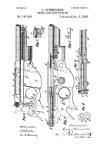
RECOIL CHECK FOR ORDNANCE.
5 Sheets—Sheet 2.
fNo Model.)
J. B. G. A. CANET.
RECOIL CHECK FOR ORDNANCE.
(No Model.)
5 Sheets—Sheet 3.
J. B. G. A. CANET.
RECOIL CHECK FOR ORDNANCE.
No. 522,508.
Patented July 3, 1894.
‘ (No Model.)
5 Sheets—Sheet 4.
J. B. G. A. CANET.
RECOIL CHECK FOB ORDNANCE.
(No Model.)
5 Sheets—Sheet 5.
J. B. G. A. CANET.
RECOIL CHECK FOR ORDNANCE.
No. 522,508. Patented July 3, 1894.
United States Patent Office.
JEAN BAPTISTE GUSTAVE ADOLPHE CANET, OF PARIS, FRANCE.
RECOIL-CHECK FOR ORDNANCE.
SPECIFICATION forming part of Letters Patent No. 522,508, dated, July 3,1804.
Application filed February 9,1893, Serial Ho. 481,616. (Ho model.) Patented in France October 23,1891, Ho, 216,937.
To all whom it may concern:
Be it known that I, Jean Baptiste Gustave
Adolphe Canet, engineer, a citizen of the
Republic of France, and a resident of Paris,
5 France, have invented certain new and useful
Improvements in and Relating to Gun-Moun t-
ings, (for which I have obtained a patent in
France, No. 216,937, dated October 23, 1891,)
of which the following is a specification, refer-
ro ence being had to the accompanying draw-
ings. _ .
This invention relates to gun mountings.
According to one construction, a sleeve in
which the gunslidesis form ed on or attached to
15 side framesorcheeks which are provided with
trnduions, and in the said sleeve or attached
thereto on the lower side thereof is provided
a single hydraulic brake cylinder the piston
rod of which is attached to a hoop or ring
20 fixed on the gun. The Said hoop or ring slides
on the said side frames or cheeks during the
recoil and running out of the gnu. In a
slightly modified form of construction, an ad-
ditional sleeve through which the gnn slides
25 is formed on the side frames, and the brake
cylinders are arranged at the sides of the gun.
The said invention also comprises the pro-
vision of subsidiary hydraulic cylinders for
running the gun in and out when desired
30 without firing, and also a novel recuperator
in combination with the said sleeve, hoop or
ring, and side frames.
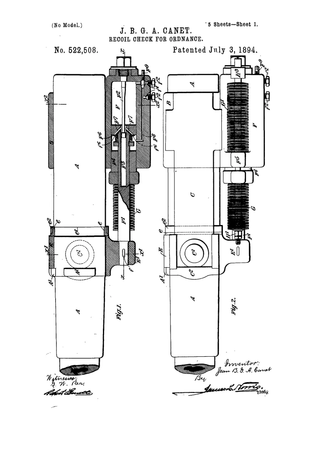
In the accompanying drawings, Figure 1 is
a vertical central section of the recuperator
35 cylinder and sleeve, and hoop or ring, fixed to
the gun, and showing also in side elevation a
portion of the gun. Fig. 2 is a side elevation
of the guu and mounting. Fig. 3 is a hori-
zontal section on the line x, x Fig. 1. Fig. 4
40 is a half front elevation and half section on
the line x' x' Fig. 1. Fig. 5 is a half rear ele-.
vation and half section on the line »2 sc3 Fig.
1. Fig. 6 is a half plan and half horizontal
central section through the side frames and
45 sleeve. Fig. 7 is a side elevation of a portion
of the gun and slightly modified mounting
constructed with brake cylinders at the sides
of the gun. Fig. 8 is a longitudinal section
of the mounting on the line y3 y3 Fig. 10,
50 showing the gun in side elevation. Fig. 9 is
a half plan and half horizontal central sec-
tion of the said mounting. Fig. 10 is a half
rear elevation, and half section on the line у
у Fig. 9. Fig. 11 is a half front elevation and
half section On the line y' Fig. 9. Fig. 12 55
is a section on the line- y3 y3 Fig. 9. Fig. 13
shows in side elevation partly in section an
air or gas recuperator hereinafter described.
Fig. 14 is a vertical central section of a mount-
ing constructed accordingtoa furthermodifi- 60
cation of my invention, aportion of thegun be-
ing shown in side elevation. Fig. 15 is a hori-
zontal section on the line z z, Fig. 14. Fig. 16
is a section on the line 'z' z' Fig. 14. Fig. 17
is a section on the line 23 z3 Fig. 14. 65
Like letters denote corresponding parts
throughout the drawings.
Referring to Figs. 1 to 6, A is the gun; В
is a sleeve through which the gun can slide;
С, C are'side frames cast with or fixed to the 70
sleeve B; C'C' arethe trunnions formedonor
fixed to the said side frames. D, Fig. 4, rep-
resents a portion of. the carriage. E is a hoop
or ring fixed to the gun and adapted to slide
on the side frames C. 75
The sleeye.B is made in oneor several parts,
and has cast on itorattached to it a hydraulic
brake cylinder F below the gun. The piston
rod F' of this cylinder is attached at its for-
ward extremity by a collar/Figs. 1 and 4 to 80
a projection E' on the hoop or ring E which
is suitably secured to the exterior surface of
the gun. In the construction shown in Figs.
1, 2 and 4 the hoop E is secured between pro-
jections A' formed on the gun and a hoop e 85
constructed in halves and held by means of
a ring e2 in a recess e' formed in the gun. The
projections A' constitute an interrupted col-
lar on the gun. The hoop E is made with
parts that project into and fit in the inter- 90
ruptions of the said collar and thus prevent
the gun from turning in the hoop during the
recoil. The said ring may be otherwise se-
cured to the gun, for example, it may be placed
while hot upon the gun and shrunk into its 95
place thereon.
The side frames С, C serve as slides along
which the hoop E, which is suitably recessed
or grooved at e3 e3 Fig. 4 for the purpose,
moves in its recoil’ and return. These side 100
frames may or may not be braced by suitable
trunnions and may be provided at the rear
with stops or buffers to diminish the shock of
recoil. A stop C2 is fixed in the forward end
2
622,508
of each side frame or beam to limit the for-
ward movement of the gun.
The hydraulic brake employed in this
mounting, is furnished with a taper rod F3
5 arranged to enter a central aperture F3in the
piston for the purpose of regulating in a well
known manner the area of the opening
through which the liquid, displaced by the en-
trance into the cylinder of the piston rod F',
io flows from one to the other side of the piston
during'the recoil. The liquid so displaced
operates to force outward the loose head F4
of the brake cylinder and thereby coinpresses
a spring recuperator which serves to run out
15 the gun at the end of the recoil. The recu-
peratorconsists of springsGGG'G', threaded
upon rods H. The springs G G bear at their
rear ends against the front of the head F4
and at their forward ends against nuts II'
20 screwed on the rods II. The springs G' G'
bear at their forward ends against a flange
F5 of the brake cylinder and at their rear ends
against shoulders II2-formed on the rods II.
II3 is a piece secured to the brake cylinder
25 and forming a guide for the rear ends of the
rods H.
A spring loaded valve F6 which is mounted
on the piston rod in front of the piston is
raised from its seat by the pressure of the
30 liquid flowing through orifices F7F7 from one
to the other side of the piston during the re-
coil, and returns to its seat when the recoil is
finished thus preventing the return of the
liquid and maintaining the gun run in until
35 a return thoroughfare is opened. This valve
is in some cases perforated with small by-
pass orifices /6 which allow of the slow return
of the liquid and thus permit of the immedi-
ate commencement of the running out of the
40 gun under the action of the recuperator while
however moderating the speed of the run-
ning out.
F8 Fig. 1 is a passage formed in the wall of
the brake cylinder and communicating with
45 the ends of the said cylinder on opposite sides
of the piston. The, area of opening of this
passage can be regulated or the said passage
can be closed entirely by means of an adjust-
able, valve composed of a conical screw plug
50 F“ which is adapted to be screwed down upon
a seat formed in the metal around the pas-
sage. By means of the adjustable screw-valve
controlling the passage or thoroughfare Fs
the speed of running out can be regulated at
55 will. Orifices/'/'are made leading into the
said passage F“ on opposite sides of the screw-
down valve F" into which orifices can be in-
serted the delivery pipe of a pump in case it
should be necessary or desirable to use the
60 same for running the gun in and out of bat-
tery. When a pump is not in use for the
purpose the said orifices are closed by screw
plugs /2/2. The action of the brake cylin-
der is well understood and need not be fur-
65 ther explained here.
The mounting illustrated in Figs. 7 to 12
possesses the same general characteristics as
those above described, that is to say, it com-
prises the rear sleeve В to which are attached
the side frames, beams, or chooks С, C but 70
there is a difference in respect of the arrange-
ment of the brake cylinders F of which ac-
cording to this part of the invention there are
two placed one on each side of the sleeve B.
In this mounting is also provided a forward 75
sleeve B' in front of the fixed hoop or ring E.
The trunnions are formed on the sleeve B'
and project through and fit into openings C3
provided in the side frames C. The sleeve B'
is fitted with bushes В2 B2 which can be re- 80
meved when worn and replaced by new ones.
The side frames C are made with central
openings which form guides for the hoop or
ring E that is constructed to slide therein dur-
ing the recoil and running out of the gun. 85
The construction of the brake cylinders is
similar to that above described, but in this
case the excess of liquid expelled by the en-
trance of the piston rods into the brake cyl-
inders, passes out through pipes F10 which 90
communicate with a valve box J containing a
spring loaded non-retnrn valve E° and raises
said outlet valve and passes along a pipe cto
a reservoir of compressed gas or air К Fig. 13
or into an air recuperator under spring press- 95
ure. The said air or gas recuperator is con-
structed of one or more hollow cylinders K'
connected to each other at both ends by pipes
К2, K3 and provided with pistons K4 above
which is the air or gas under pressure. The too
liquid enters the recuperator at the lower end
below the said pistons which are covered by
a slight depth of liquid. This arrangement
effectively prevents the escape of the air or
gas under pressure iu the recuperator. 105
A passage J' Fig. 8 fitted with a plug or
screw-down stopper J2 is provided to permit
the liquid to re-enter the brake cylindersand
force the gun back into battery when required.
A special device is shown in Figs. 8 and 10 no
which allows the gun to be moved into and
out of battery at will. This device comprises
two or more hydraulic cylinders L mounted
or formed on the sleeve В and provided with
pistons I/ the rods L2 of which are normally 115
or under ordinary conditions locked by pinsl?
passing through the same and through a piece
L4 fixed to the cylinder. The forward end Lsof
each piston rod is adapted to be coupled by a
pin for example to a stud L° or the like fixed in 120
the hoop or ring E. For running the gun in,
it will bo sufficient to disengage the pins L3,
move the piston rods L2 forward, connect the
said rods to the studs L° and then inject liq-
uid under pressure in front of the pistons L' 125
of said hydraulic cylinders. The mounting
shown in Figs. 14 to 17 is also characterized
by substantially the same features in respect
of the rear sleeve and the side frames or
cheeks furnished with trunnions. The said 130
frames or cheeks however in this modifica-
tion are united at their forward ends by a
piece B' cast on or otherwise attached thereto
and forming with a cover or cap B3 a sleeve
622,508
3
which embraces the gun. A bronze bush B2
is preferably inserted in the said sleeve. This
sleeve carries stops C2 in the form of buffers
to limit the outward run of the gun. The
5 side.frames С C are formed with projecting
portions С4 C4 to serve as guides to a projec-
tion E3 formed*on the hoop or ring E which
is solid with thegun and to which projection
is secured the end of the brake piston rod F'.
ro N is a recuperator cylinder placed behind
the brake cylinder and fitted with a ram N'
that presses" against a head F4 that bears upon
the recuperator springs G. The recuperator
cylinder communicates with the brake cylin-
15 der by a passage О in which is placed a valve
F6. The passage О permits the liquid ex-
pelled from the brake cylinder during recoil
by the entrance thereinto of the piston rod
F' to pass into the recuperator cylinder after
2o raising the spring loaded valve F6. This
valve is perforated with small orifices /6 to
permit the liquid to return and run thegun
out again. A thoroughfare P connects the
passage 0 with the rear end of the brake cyl-
25 inder. This thoroughfare is adapted to be
closed by a screw down valve P'. Orifices^,
p are made into this passage one on each side
the valve P' adapted to receive the delivery
pipe of a pump whereby the gun can be run
30 in or out without firing.
What I claim is—
1. In a gun mounting, the combination of
a sleeve through which the gun slides, a brake-
cylinder and side beams or frames on the
35 sleeve, trunnions on the side beams or frames,
..a hoop fixed to ihe gun, attached .to’ the pis-
ton-rod of the brake-cylinder, and sliding on
the said side beams or frames during the re-
coil and runningoutof thegun, substantially
'40 as. described.
2. In qgun mounting, a hydraulic brake ap-
paratus comprising a cylinder, a piston and
hollow piston rod, apertures leading through
to the front of the piston from the interior of
45 the rod, a taper spindle secured to the cylin-
der end and adapted to enter the piston rod
and control the area of the outlet opening for
the liquid during recoil, a thoroughfare form-
ing a communication between the ends of the
50 brake cylinder on opposite sides of the pis-
•- ton, and an adjustable screw-valve operated
from the exterior of the brake-cylinder for
controlling said thoroughfare and regulating
the speed of running out the gun, substan-
, 55 tially as described, for the purpose specified.
3; In a gun mounting, a hydraulic brake ap-
paratus comprising a cylinder, a piston qud
hollow piston rod, apertures leading through
to the front of .the piston from the interior of
60 . the rod, a spring loaded non-return valve for
closing said apertures to allow the liquid to
. flow therethrough in one direction only, a ta-
per spindle secured to the cylinder end and
adapted to enter the piston rod and control
the area of the outlet opening for the liquid 65
during recoil, a thoroughfare forming a com-
munication between the ends of the brake
cylinder on opposite sides of the piston, and
an adjustable screw-valve operated from the
exterior of the brake-cylinder for controlling 70
said thoroughfare and regulating the speed
of running ont the gun, substantially as set
forth for the purpose specified.
4. In a gun mounting, a hydraulic brake ap-
paratus comprising a cylinder, a piston and 75
hollowpistonrod,aperturesleadingthrough to
the front of the piston from the interior of the
rod, a spring loaded perforated valve placed
over said apertures, which valve allows the
liqnid to flow freely in one direction through 80
the apertures, but only allows of a slow flow
in the other direction through the perfora-
tions in the valve, a taper spindle secured to
the cylinder end and adapted to enter the pis-
ton rod and control the area of the outlet 85
opening for the liquid during recoil, author-
oughfare forming a communication between
the ends of the brake cylinder on opposite
sides of the piston, and an adjustable screw
valve operated from the exterior of the brake- 90
cylinder for controlling said thoroughfare
and regulating the speed of running out the
gun, substantially as set forth for the purpose
specified.
5. The combination with a gun, of a hy- 95
draulic brake-cylinder, a thoroughfare formed
in the cylinder to communicate with the op- -
posite'ends thereof, an adjustable screw-down
valve operated from the exterior of the cylin-.
der for closing said thoroughfare, and aper- юг
tures leading into the thoroughfare at oppo-
site sides of the adj ustable screw-down valve
for receiving-the delivery pipe of a force .
pump to run the gun in or out when the ad?
justable screw-down valve is closed, substatt* 105
tially as described. . _ '
6. The combination with a gun, of a hy- .
draulic brake-cylinder,a thoroughfareformed
in the cylinder to communicate with the op-
posite ends thereof, an adjustable screw-down 110
valve for closing said thoroughfare, and ap-
ertures leading into the thoroughfare at op-
posite sides of the adjustable screw-down,
valve and provided with non-return valves,"
said apertures being adapted to receive the 115
delivery-pipe of a force pump to run thegnn
in or out when the adjustable screw-down
valve is closed, substantially as described. .
In witness whereof ! have hereunto set my
hand this 20th dav of January, 1893.
JEAN BAPTISTE GUSTAVE ADOLPHE CANEf
Witnesses:
Robt. M. Hooper,
Ch. F. Thirion.