/

Tags: weapons military affairs patent
Year: 1897
Text
(No Model.)
11 Sheets—Sheet 1.
H. S. MAXIM.
RECOIL OPERATED GUN.
No. 579,401.
Patented Mar. 23, 1897.
11 Sheets—Sheet 2.
(No Model.)
No. 579,401.
H. S. MAXIM.
RECOIL OPERATED (Ш
Patented Mar. 23, 1097.
by Jt&rnesr.
11 Sheets—Sheet 3.
H. S. MAXIM.
RECOIL OPERATED GUN.
(No Model.)
No. 579,401.
Patented Mar. 23, 1897.
If trajn S.Maj/m., J/e&e/e&rr’
(No Model.)
11 Sheets—Sheet 4.
H. S. MAXIM.
RECOIL OPERATED GUN.
No. 579,401 Patented Mar. 23, 1897.
JZiram. S.jtfaacim,, Tnvent#/*
. /Ly..
(No Model.)
11 Sheets—Sheet 5.
H. S. MAXIM.
RECOIL OPERATED GUN..
No. 579,401.
Patented Mar. 23, 1897.
rig. 7.
Jfiramy S-Aff/xim^Inver^r
01/ I: JiMrriey.
11 Sheets—Sheet 6.
H. S. MAXIM.
RECOIL OPERATED GON.
(No Model.)
No. 579,401.
Patented Mar. 23, 1897.
Fig.8.
Wiln£&sest
JTira/r? J-nventor’
I'CUtJ<JLJ\AA>.
by a Atto/vtey
11 Sheets—Sheet 7.
H. S. MAXIM.
RECOIL OPERATED GUN.
(No Model.)
No. 579,401.
Patented Mar. 23, 1897.
Fig.9.
Witnesses:
.ffFsrt/rrbS.Jtfcwccm , TjtvenZo?
(No Model.)
No. 579,401.
11 Sheets—Sheet 8.
H. S. MAXIM. ---
RECOIL OPERATED GUN.
Patented Mar. 23, 1897.
Witnesses:
(No Model.) 11 Sheets—Sheet 9.
H. S. MAXIM.
RECOIL OPERATED GUN.
No. 579,401. Patented Mar. 23, 1897.
(No Model.)
11 Sheets—Sheet 10.
H. S. MAXIM.
RECOIL OPERATED GUN.’
No. 579,401.
Patented Mar. 23, 1897.
(No Model.)
11 Sheets—Sheet 11.
H. S. MAXIM.
RECOIL OPERATED GUN.
No. 579,401.
fi'iff.?/.
Patented Mar. 23, 1897.
pi^.22.
United States Patent Office.
HIRAM STEVENS MAXIM, OF LONDON, ENGLAND.
RECOIL-OPERATED GUN.
SPECIFICATION forming part of Letters Patent No. 579,401, dated March 23, 1897.
Application filed January 22,1896. Serial No. 576,436.' (No model.) Patented in France December 17, 1895, No. 252,554;
in Belgium December 18,1895, No, 118,922; in Switzerland December 18,1895, No. 11,655; in Italy December 21,1895,
LXXIX, 176; in Brazil February 4.1896, No. 2,003; in Canada February 18,1896. No. 51,386; in Austria March 26,1896,
No. 46/1,151, and in Argentine Bepnblic April 10,1896, No. 1,786.
To all whom it map c.on.eern:
Be it known that I, Hiram Stevens Maxim,
mechanical engineer, a citizen of the United
States of America, residing at 18 Queen’s Gate
5 Place, London, England, have invented cer-
tain new and useful Improvements in Auto-
matic Guns, of which the following is a speci-
fication, reference being had to the accom-
panying drawings.
io I have obtained patents for this invention in
the following countries: France, No. 252,554,
dated December 17, 1895; Belgium, No.
118,922, dated December 18, 1895; Austria,
No. 46/1,151, dated March 26,1890; Italy,
15 No. LXXIX, 176, dated December 21, 1895;
Switzerland, No. 11,655, dated December 18,
1895; Argentine Republic, No. 1,780, dated
April 10, 1896; Canada, No. 51,386, dated
February 18,1896, and Brazil, No. 2,003,dated
20 February 4, 1896.
This invention relates to automatic or
“Maxim” guns, and has for one of its objects
to devise improved means for actuating the
cartridge-carrier whereby the latter is caused
25 to entirely complete its upward movement
before the breech block or lock terminates its
forward movement in closing the breech.
Another object of my present invention is
to so construct the muzzle device employed
30 for increasing the energy of the recoil move-
ment of the gun-barrel that a quantity of wa-
ter can at each recoil of the barrel be caused
to enter the gas-chamber of the aforesaid
muzzle device and the passages communicat-
35 ing therewith for the purpose of preventing
the corrosion or incrustation of these parts
by the gases of discharge, and also for pre-
venting the muzzle of the barrel and the muz-
zle device from becoming overheated.
40 A still further object of this invention is to
devise improved means for controlling the
speed of firing the gun.
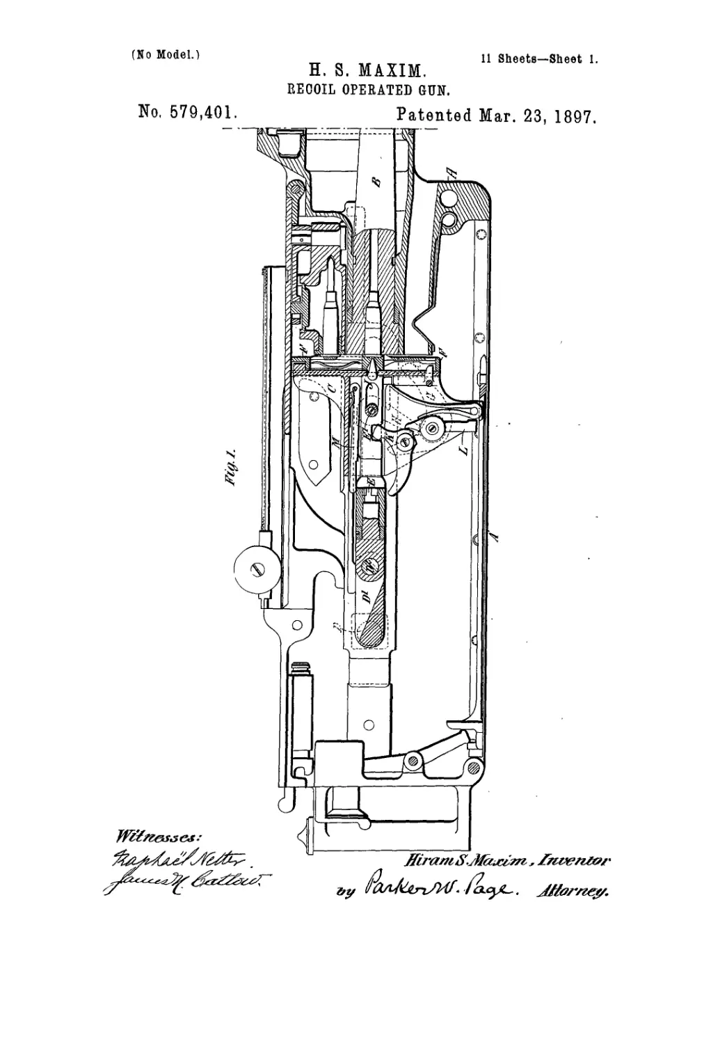
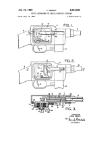
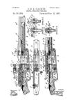
In the accompanying drawings, Figures 1
to 7 illustrate the improved means for actu-
15 ating the cartridge-carrier, Fig. 1 being a lon-
gitudinal section of the breech mechanism of
a gun provided with my improved cartridge-
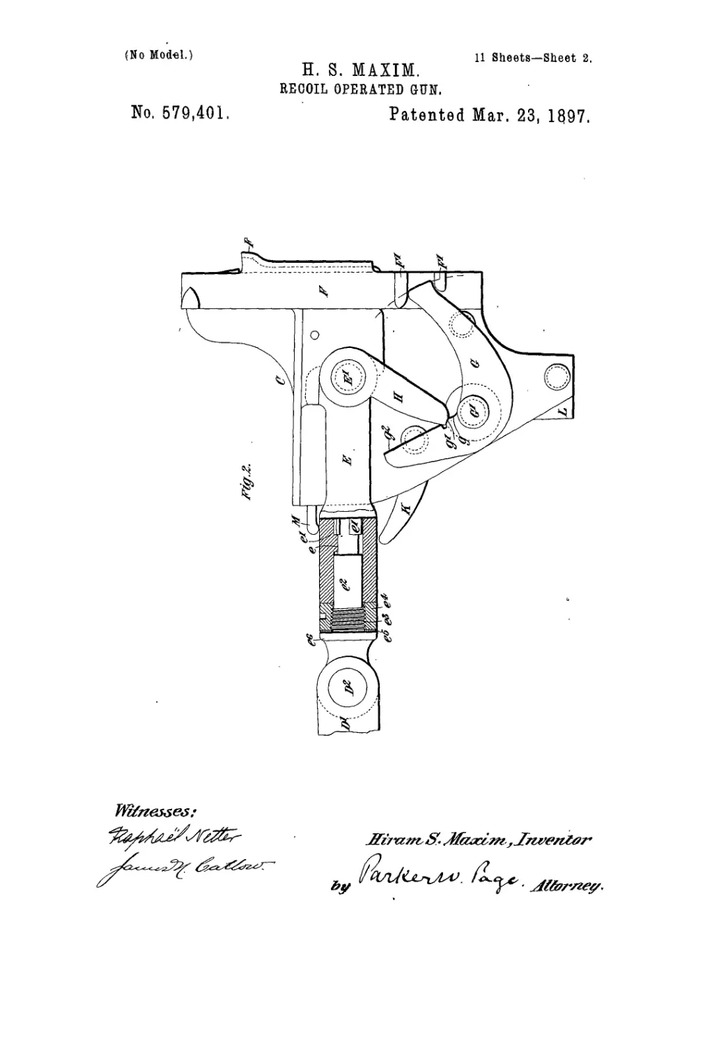
carrier; Fig. 2, a detached sectional elevation
showing the breech block or lock and parts
connected therewith in a firing position; Fig. 50
3, a similar view showing the parts in a re-
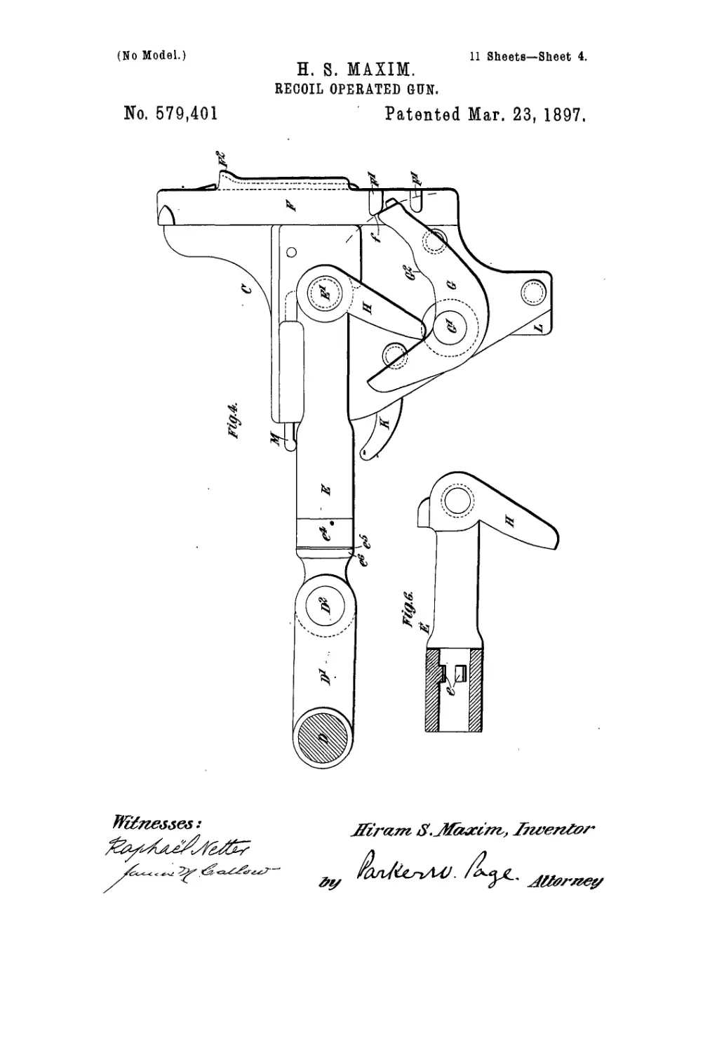
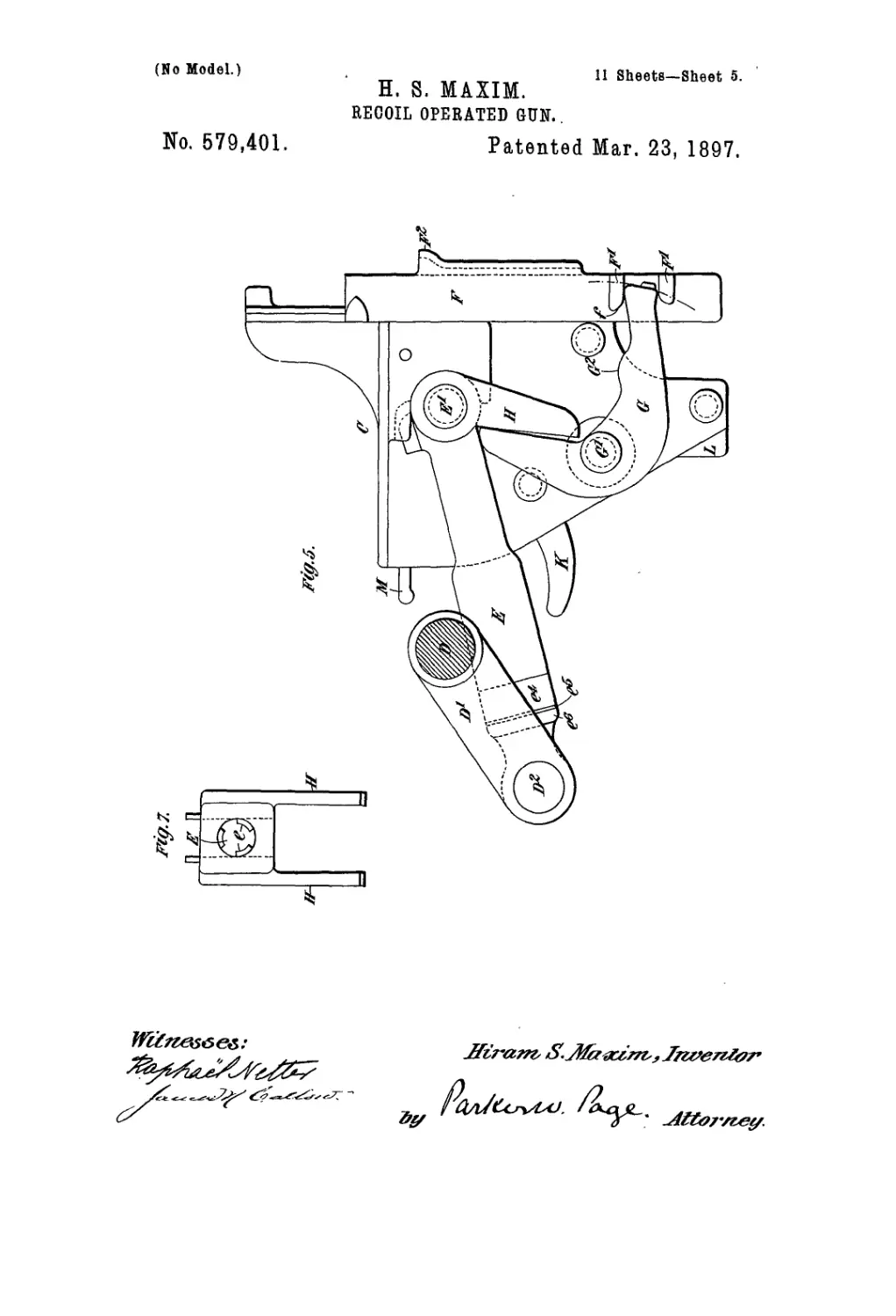
coiled position; Figs. 4 and 5, sectional ele-
vations similar to Figs. 2 and 3, but showing
a modified construction; and Figs. 6 and 7, a
longitudinal section and rear end view of a 55
detail hereinafter more fully referred to.
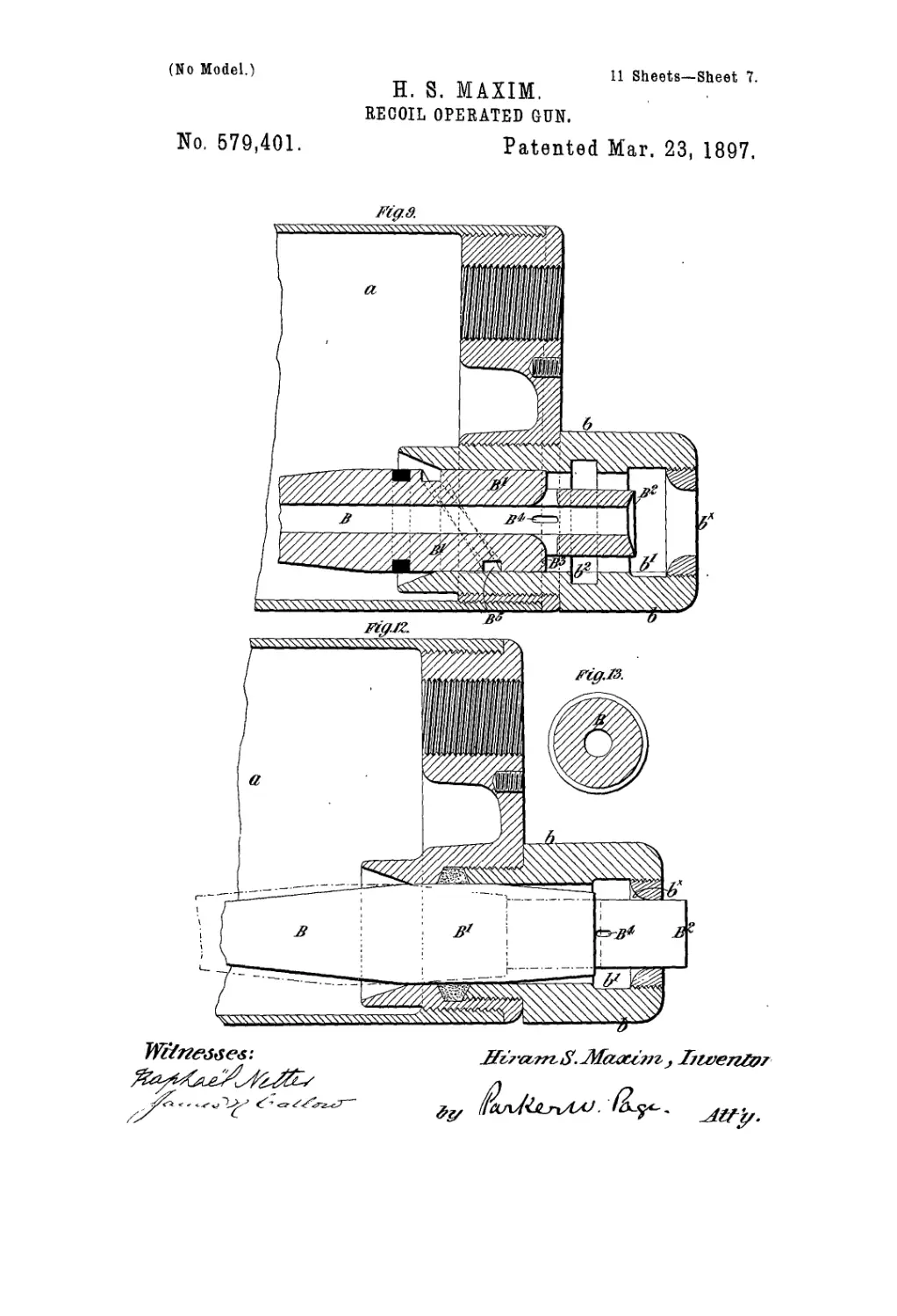
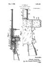
Figs. 8 to 15 illustrate the muzzle device pro-
vided with means for admitting a quantity of
water thereto each time the barrel recoils,
Fig. 8 being a longitudinal section with the 60
gun-barrel in its forward position; Fig. 9, a
similar view with the gun-barrel in its re-
coiled position; Fig. 10, another longitudinal
section showing a modification; Fig. 11, a
transverse section of the gun-barrel employed 65
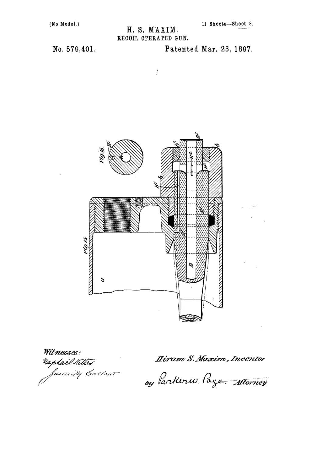
in this modification. Figs. 12 and 13 are
similar views to Figs. 10 and 11, but show
another modification; and Figs. 14 and 15 are
also similar views to Figs. 10 and 11, but show
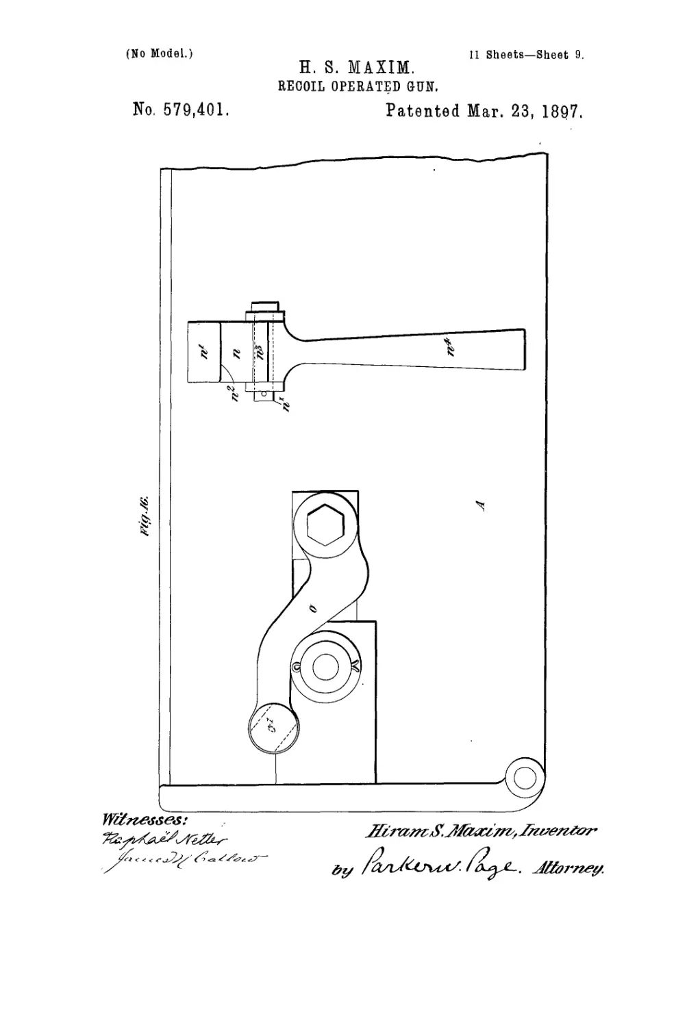
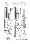
a still further modification. Figs. 16 to 24 70
illustrate the improved means or devices for
controlling the speed of firing the gun. In
these figures Fig. 16 is a side elevation of the
rear portion of the gun, showing one of the
said devices applied thereto, and Figs. 17,18, 75
19, and 20 are central vertical sections of this
device in different positions. Fig. 21 is a
front elevation, and Fig. 22 a central vertical
section, of a modified construction of the de-
vice. Fig. 23 is a front elevation, partly in 80
section, and Fig. 24 a vertical section, of a
further modified construction of the device.
I will first refer to that part of my inven-
tion relating to the means for actuating the
cartridge-carrier. 85
In automatic or Maxim guns as at present
constructed there-is on the forward end of
the breech block or lock a cartridge-carrier
or sliding piece which acts to simultaneously
withdraw the empty cartridge-case from the 90
barrel and a fresh or loaded cartridge from
the belt, then to lower the said cartridge and
cartridge-case, then to thrust the fresh car-
tridge into the barrel and the empty car-
tridge-case out through the ejecting-orifice, 95
and then, finally, to engage with another car-
tridge in the belt ready to repeat its cycle of
operations upon the next discharge of the gun.
579,401
The said carrier thus has four movements— 1
viz., a backward movement with the lock, a |
downward sliding movement on the lock, a
forward movement with the lock, and, lastly,
5 an upward sliding movement on the lock. In
order that the last of these four movements
may be properly performed, it is necessary to
prevent undue pressure between the face of
the carrier and the base of the cartridge,
io Otherwise the carrier would bind against the
cartridge. Consequently the space usually
left between the face of the carrier and the
end of the gun - barrel when the carrier is
in its most forward position is slightly in ex-
15 cess of the thickness of the flange or rim of
the cartridge. It follows, therefore, that when
the breech is closed the cartridge is not firmly
supported. This evil is aggravated when
modern smokeless powders are used, for in
20 such instances the primers have to be made
sufficiently thick to resist an enormous pres-
sure, and therefore a very strong blow of the
firing-pin is required to make them detonate.
The force of this blow not only pushes the
25 lock back, but also pushes the cartridge for-
ward or away from the face of the carrier, and
any lost motion in the parts or any allowance
made for thick or dirty cartridges serves to
increase the distance between the face of the
30 carrier, and the base of the cartridge, so that
when the gun is fired the cartridge recoils
through such distance, and this movement,
together with that arising from the elasticity
of the side plates, the crank, and the connec-
35 tions, will be sufficient in many cases, when
the metal of the cartridge is not of the very
best quality, to break the cartridge into two
pieces, one of which remains in the cartridge-
chamber and thereby stops the firing. In or-
40 der to obviate this difficulty, I have accord-
ing to my present invention devised means
whereby the cartridge carrier or slide is
caused to perform five functions instead of
four, as heretofore—that is to say, it acts, first,
45 to draw a cartridge from the belt; second, to
lower it into position for loading; third, to
thrust it into the barrel; fourth, to rise and
seize a new cartridge, and, fifth, to close firmly
against the base of the cartridge in the car-
50 tridge-ehamber. The energy possessed by the
erank at the moment of closing the breech and
heretofore generally absorbed by the “dead-
stop” is by this improvement utilized, through
the toggle formed by the erank and its con-
55 necting-rod, to press the carrier firmly against
the base of the cartridge, so that at the instant
of firing the cartridge is firmly held in the
cartridge-chamber and all lost motion is taken
up. I provide means for adjusting the length
<60 of the said connecting-rod to accommodate
cartridges having base-flanges of different
thicknesses.
In the present most common forms of the
Maxim gun the hand-sear is release^ just
65 prior to the completion of the upward move-
ment of the carrier, and the safety-sear is
operated to release the firing-pin at the exact
instant that the carrier reaches its highest po-
sition. This construction necessitates a very
fine adjustment of the parts, and it is found 70
that when slightly worn the parts get out of
adjustment and do not properly operate; but
with my present improvements, whereby the
carrier first completes its vertical movement
and then the crank-handle travels through an 75
appreciable angle to press the carrier against
the base of the cartridge, such very fine ad-
justment of the parts is unnecessary and the
difficulty above indicated is avoided. More-
over, the present improvements obviate the 80
inconvenience sometimes heretofore caused
by the rebounding of the carrier after it has
been fully raised, thus bringing the firing-pin
hole in the carrier a little below the center of
the primer. In such cases the action of the 85
firing-pin is interfered with and the said pin
is sometimes broken.
The spring that is generally attached to one
of the inside plates of the gun and that en-
gages with a notch in the carrier and holds it 90
in its uppermost position at the instant of
firing may be dispensed with.
Referring to Figs. 1 to 7 of the accompany-
ing drawings, A is the frame inclosing the )
breech mechanism. В is the barrel. Cis the 95
breech-block or lock-body. D is the crank-
shaft. D'is the crank. D2 is the crank-pim. (
E is'tinrconnecting-rod coupling the crank to !
the lock. E' is the pin connecting the rod E ।
tothelock. F is the cartridge-carrier mounted to<
w ith a capability of sliding up and down on
the forward end of the lock-body. G is one
of the side levers for raising and lowering
the cartridge-carrier. The said lever is piv-
oted to the lock-body at G'. F F' are lugs io:
on the side of the cartridge-carrier, between
which the forward end of the lever G works. .
II is an arm or finger forming part of the con-
necting-rod and adapted to operate the lever
G. There is one such arm II and one such n
lever G on. each side of the lock. J is the fir-
ing-pin. К is the tumbler. L is the hand-
sear. M is the safety-sear. Except as here-
in .fter described all of the aforesaid parts
are constructed and operate as heretofore. 11
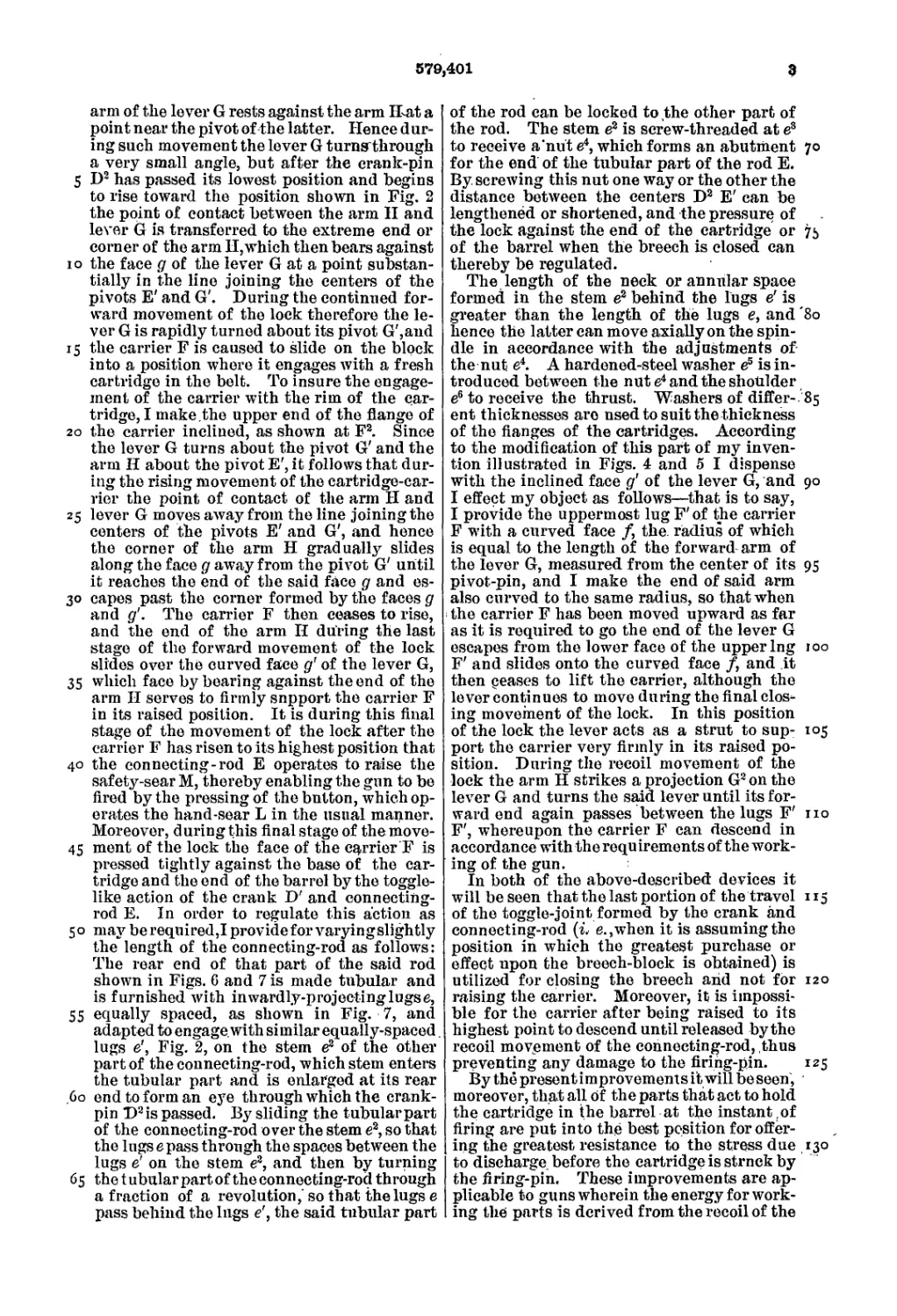
Referring now to Figs. 2 and 3, the lever G
is constructed with a working face g, (against
which the end of the arm II bears during the
greater part of the to-and-fro movement of
the lock,) a curved face д', inclined to the face j 2
<7, and a face <?2, the plane of which is behind
the plane of the face g. The corner between
the curved face д' and the face gi may be re-
cessed, as indicated at g3, or the said two faces
may be constructed to merge one into the 12
other. The radius of curvature of the face
д' is equal to the length of the arm II, meas-
ured from the center of its pivot to its ex-
treme end, which is curved to the same radius.
In some instances the face д' is made straight 13
instead of curved. During the first part of
the forward movement of the lock from the
extreme position of recoil (shown in Fig. 3) the
extreme end or corner of the nearly vertical
579,401
9
arm of the lever G rests against the arm That a
point near the pivot of the latter. Hence (lur-
ing such movement the lever G turnsthrough
a very small angle, but after the crank-pin
5 D2 has passed its lowest position and begins
to rise toward the position shown in Fig. 2
the point of contact between the arm II and
lever G is transferred to the extreme end or
corner of the arm H,which then bears against
io the face g of the lever G at a point substan-
tially in the line joining the centers of the
pivots E' and G'. During the continued for-
ward movement of the lock therefore the le-
ver G is rapidly turned about its pivot G',and
15 the carrier F is caused to slide on the block
into a position where it engages with a fresh
cartridge in the belt. To insure the engage-
ment of the carrier with the rim of the car-
tridge, I make.the upper end of the flange of
20 the carrier inclined, as shown at F2. Since
the lever G turns about the pivot G' and the
arm H about the pivot E', it follows that dur-
ing the rising movement of the cartridge-car-
rier the point of contact of the arm H and
25 lever G moves away from the line joining the
centers of the pivots E' and G', and hence
the corner of the arm H gradually slides
along the face g away from the pivot G' until
it reaches the end of the said face g and es-
30 capes past the corner formed by the faces g
and д'. The carrier F then ceases to rise,
and the end of the arm H during the last
stage of the forward movement of the lock
slides over the curved face д' of the lever G,
35 which face by bearing against the end of the
arm II serves to firmly snpport the carrier F
in its raised position. It is during this final
stage of the movement of the lock after the
carrier F has risen to its highest position that
40 the connecting-rod E operates to raise the
safety-sear M, thereby enabling the gun to be
fired by the pressing of the button, which op-
erates the hand-sear L in the usual manner.
Moreover, during this final stage of the move-
45 ment of the lock the face of the carrier F is
pressed tightly against the base of the car-
tridge and the end of the barrel by the toggle-
like action of the crank D' and connecting-
rod E. In order to regulate this action as
50 may be required,! provide forvaryingslightly
the length of the connecting-rod as follows:
The rear end of that part of the said rod
shown in Figs. 6 and 7 is made tubular and
is furnished with inwardly-projectinglugse,
55 equally spaced, as shown in Fig. 7, and
adapted to engage, with similar equally-spaced
lugs e', Fig. 2, on the stem e2 of the other
part of the connecting-rod, which stem enters
the tubular part and is enlarged at its rear
.60 end to form an eye through which the crank-
pin D2 is passed. By sliding the tubular part
of the connecting-rod over the stem e2, so that
the lugs e pass through the spaces between the
lugs e' on the stem e2, and then by turning
65 the t ubular part of the connecting-rod through
a fraction of a revolution,’so that the lugs e
pass behind the lugs e', the said tubular part
of the rod can be locked to the other part of
the rod. The stem e2 is screw-threaded at e8
to receive a'nut e4, which forms an abutment 70
for the end of the tubular part of the rod E.
By. screwing this nut one way or the other the
distance between the centers D2 E' can be
lengthened or shortened, and the pressure of
the lock against the end of the cartridge or 75
of the barrel when the breech is closed can
thereby be regulated.
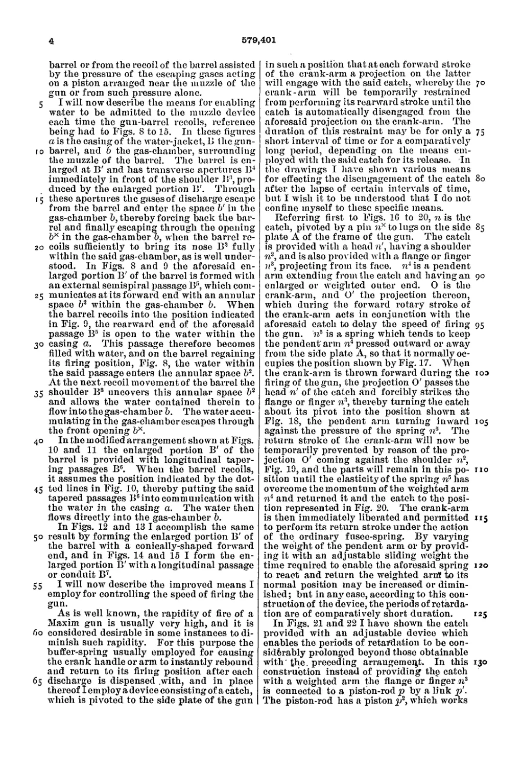
The length of the neck or annular space
formed in the stem e2 behind the lugs e' is
greater than the length of the lugs e, and '80
hence the latter can move axially on the spin-
dle in accordance with the adjustments of
the nut e4. A hardened-steel washer es is in-
troduced between the nut e4 and the shoulder
e6 to receive the thrust. Washers of differ-. 85
ent thicknesses are used to suit the thickness
of the flanges of the cartridges. According
to the modification of this part of my inven-
tion illustrated in Figs. 4 and 5 I dispense
with the inclined face д' of the lever G, and 90
I effect my object as follows—that is to say,
I provide the uppermost lug F'of the carrier
F with a curved face f, the. radius of which
is equal to the length of the forward arm of
the lever G, measured from the center of its 95
pivot-pin, and I make the end of said arm
also curved to the same radius, so that when
the carrier F has been moved upward as far
as it is required to go the end of the lever G
escapes from the lower face of the upper Ing 100
F' and slides onto the curved face f, and it
then ceases to lift the carrier, although the
lever continues to move during the final clos-
ing movement of the lock. In this position
of the lock the lever acts as a strut to sup- 105
port the carrier very firmly in its raised po-
sition. During the recoil movement of the
lock the arm II strikes a projection G2on the
lever G and turns the said lever until its for-
ward end again passes between the lugs F' no
F', whereupon the carrier F can descend in
accordance with the requirements of the work-
ing of the gun.
In both of the above-described devices it
will be seen that the last portion of the travel 115
of the toggle-joint formed by the crank and
connecting-rod (i. e.,when it is assuming the
position in which the greatest purchase or
effect upon the breech-block is obtained) is
utilized for closing the breech and not for 120
raising the carrier. Moreover, it is impossi-
ble for the carrier after being raised to its
highest point to descend until released by the
recoil movement of the connecting-rod, thus
preventing any damage to the firing-pin. 125
By the present improvements it will be seen,
moreover, that all of the parts that act to hold
the cartridge in the barrel at the instant , of
firing are put into the best position for offer-
ing the greatest resistance to the stress due 130
to discharge before the cartridge is strnck by
the firing-pin. These improvements are ap-
plicable to guns wherein the energy for work-
ing the parts is derived from the recoil of the
4
579,401
5
ю
'5
20
25
3°
35
40
45
50
55
бо
б5
barrel or from the recoil of the barrel assisted
by the pressure of the escaping gases acting
on a piston arranged near the muzzle of the
gun or from such pressure alone.
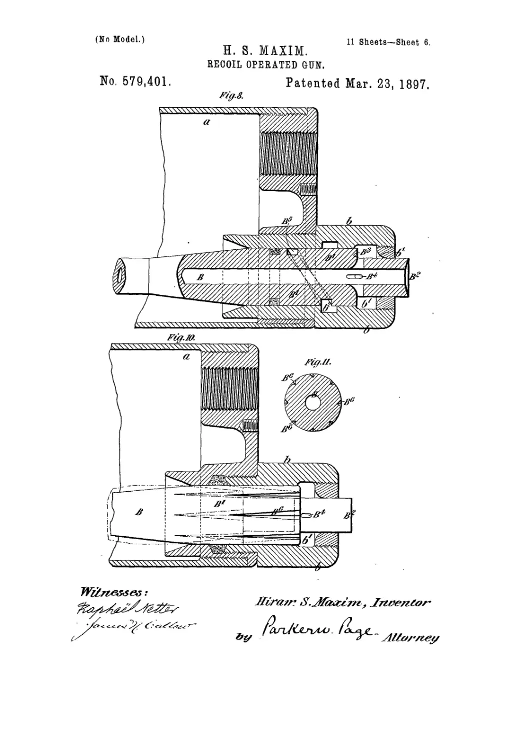
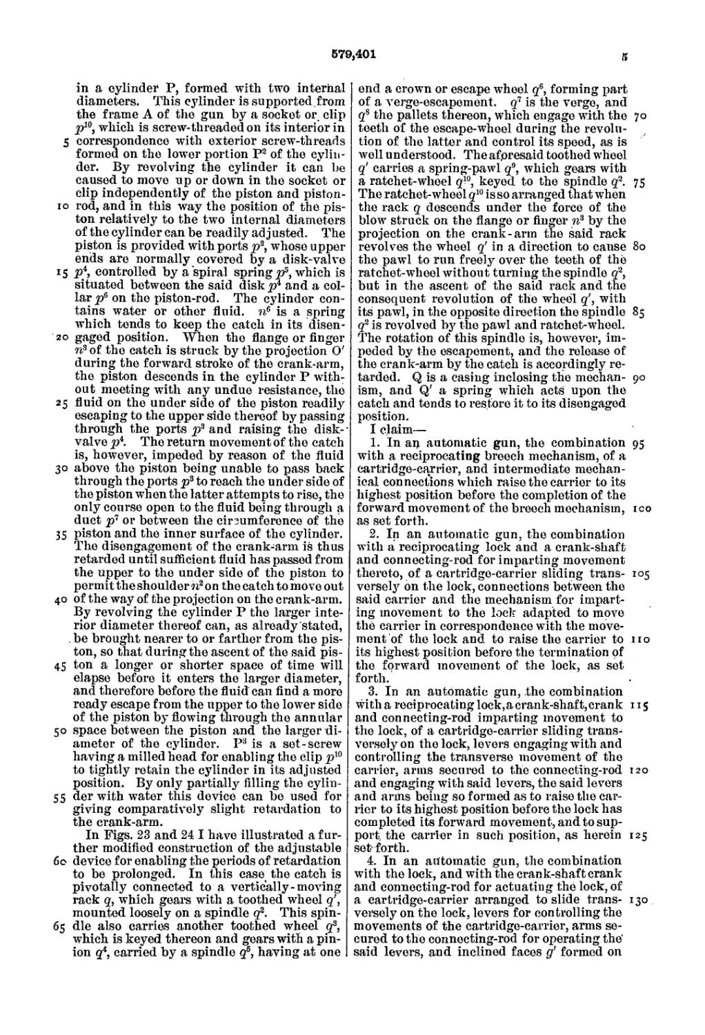
I will now describe the means for enabling
water to be admitted to the muzzle device
each time the gun-barrel recoils, reference
being had to Figs. 8 to 15. In these figures
a is the casing of the water-jacket, В the gun-
barrel, and b the gas-chamber, surrounding
the muzzle of the barrel. The barrel is en-
larged at B' and has transverse apertures B4
immediately in front of the shoulder B3, pro-
duced by the enlarged portion B'. Through
these apertures the gasesof discharge escape
from the barrel and enter the space b' in the
gas-chamber b, thereby forcing back the bar-
rel and finally escaping through the opening
bx in the gas-chamber b, when the barrel re-
coils sufficiently to bring its nose B- fully
within the said gas-chamber, as is well under-
stood. In Figs. 8 and 9 the aforesaid en-
larged portion B' of the barrel is formed with
an external semispiral passage B5, which com-
municates at its forward end with an annular
space b2 within the gas-chamber b. When
the barrel recoils into the position indicated
in Fig. 9, the rearward end of the aforesaid
passage B5 is open to the water within the
casing a. This passage therefore becomes
filled with water, and on the barrel regaining
its firing position, Fig. 8, the water within
the said passage enters the annular space b2.
At the next recoil movement of the barrel the
shoulder B8 uncovers this annular space b2
and allows the water contained therein to
flow into the gas-chamber b. The water accu-
mulating in the gas-chamber escapes through
the front opening bx.
In the modified arrangement shown at Figs.
10 and 11 the enlarged portion B' of the
barrel is provided with longitudinal taper-
ing passages B6. When the barrel recoils,
it assumes the position indicated by the dot-
ted lines in Fig. 10, thereby putting the said
tapered passages B6into communication with
the water in the casing a. The water then
flows directly into the gas-chamber b.
In Figs. 12 and 13 I accomplish the same
result by forming the enlarged portion B' of
the barrel with a conically-shaped forward
end, and in Figs. 14 and 15 I form the en-
larged portion B' with a longitudinal passage
or conduit B7.
I will now describe the improved means I
employ for controlling the speed of firing the
gun.
As is well known, the rapidity of fire of a
Maxim gun is usually very high, and it is
considered desirable in some instances to di-
minish such rapidity. For this purpose the
buffer-spring usually employed for causing
the crank handle or arm to instantly rebound
and return to its firing position after each
discharge is dispensed .with, and in place
thereof I employ a device consisting of a catch,
which is pivoted to the side plate of the gun
in such a position that at each forward stroke
of the crank-arm a projection on the latter
will engage with the said catch, whereby the 70
crank-arm will be temporarily restrained
from performing its rearward stroke until the
catch is automatically disengaged from the
aforesaid projection on the crank-arm. The
duration of this restraint may be for only a 75
short interval of time or for a comparatively
long period, depending on the means em-
ployed with the said catch for its release. In
the drawings I have shown various means
for effecting the disengagement of the catch 80
after the lapse of certain intervals of time,
but I wish it to be understood that I do not
confine myself to these specific means.
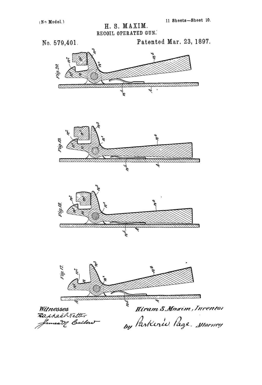
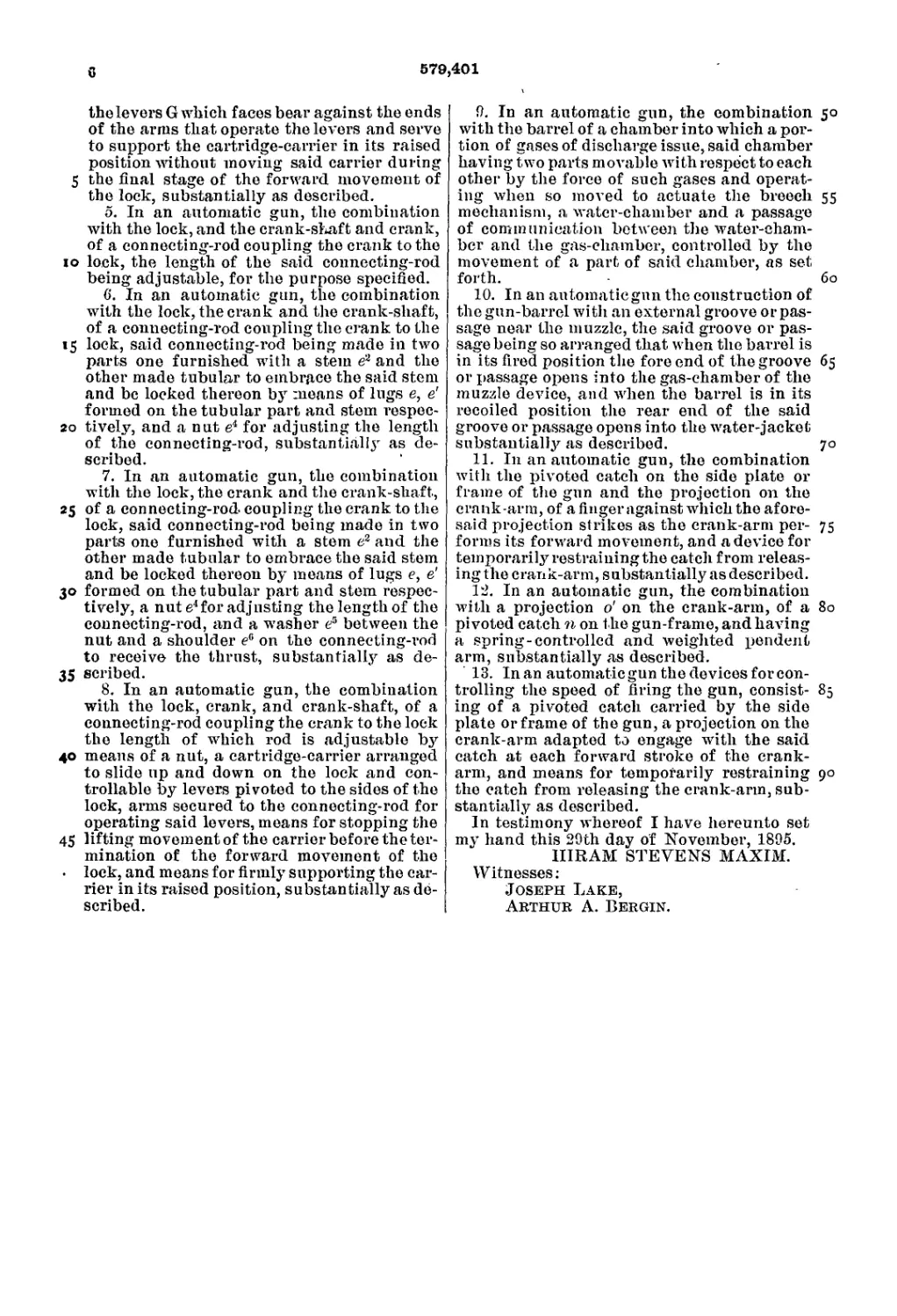
Referring first to Figs. 1G to 20, n is the
catch, pivoted by a pin nx to lugs on the side 85
plate A of the frame of the gun. The catch
is provided with a head n', having a shoulder
n2, and is also provided with a flange or finger
11s, projecting from its face, n* is a pendent
arm extending from the catch and having an 90
enlarged or weighted outer end. 0 is the
crank-arm, and O' the projection thereon,
which during the forward rotary stroke of
the crank-arm acts in conjunction with the
aforesaid catch to delay the speed of firing 95
the gun. ?i5 is a spring which tends to keep
the pendent arm n4 pressed outward or away
from the side plate A, so that it normally oc-
cupies the position shown by Fig. 17. When
the crank-arm is thrown forward during the юз
firing of the gun, the projection O' passes the
head ri of the catch and forcibly strikes the
flange or finger n2, thereby turning the catch
about its pivot into the position shown at
Fig. 18, the pendent arm turning inward 105
against the pressure of the spring n\ The
return stroke of the crank-arm will now be
temporarily prevented by reason of the pro-
jection O' coming against the shoulder n2,
Fig. 19, and the parts will remain in this po- no
sition until the elasticity of the spring nshas
overcome the momentum of the weighted arm
7i4 and returned it and the catch to the posi-
tion represented in Fig. 20. The crank-arm
is then immediately liberated and permitted 115
to perform its return stroke under the action
of the ordinary fusee-spring. By varying
the weight of the pendent arm or by provid-
ing it with an adjustable sliding weight the
time required to enable the aforesaid spring 120
to react and return the weighted arfft to its
normal position may be increased or dimin-
ished ; but in any case, according to this con-
struction of the device, the periods of retarda-
tion are of comparatively short duration. 125
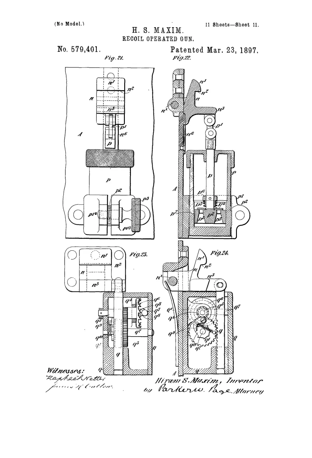
In Figs. 21 and 22 I have shown the catch
provided with an adjustable device which
enables the periods of retardation to be con-
siderably prolonged beyond those obtainable
with the. preceding arrangement. In this 130
construction instead of providing the catch
with a weighted arm the flange or finger ,n3
is connected to a piston-rod p by a link p'.
The piston-rod has a piston 7?, which works
579,401
5
in a cylinder P, formed with two internal
diameters. This cylinder is supported from
the frame A of the gun by a socket or clip
7J10, which is screw-threaded on its interior in
5 correspondence with exterior screw-threads
formed on the lower portion P2 of the cylin-
der. By revolving the cylinder it can be
caused to move up or down in the socket or
clip independently of the piston and piston-
10 rod, and in this way the position of the pis-
ton relatively to the two internal diameters
of the cylinder can be readily adj usted. The
piston is provided with ports p3, whose upper
ends are normally covered by a disk-valve
15 p\ controlled by a spiral spring p5, which is
situated between the said diskp4 and a col-
lar p6 on the piston-rod. The cylinder con-
tains water or other fluid, n6 is a spring
which tends to keep the catch in its disen-
20 gaged position. When the flange or finger
n3of the catch is struck by the projection O'
during the forward stroke of the crank-arm,
the piston descends in the cylinder P with-
out meeting with any undue resistance, the
25 fluid on the under side of the piston readily
escaping to the upper side thereof by passing
through the ports p3 and raising the disk--
valve p4. The return movement of the catch
is, however, impeded by reason of the fluid
30 above the piston being unable to pass back
through the ports p3 to reach the under side of
the piston when the latter attempts to rise, the
only course open to the fluid being through a
duct p7 or between the circumference of the
35 piston and the inner surface of the cylinder.
The disengagement of the crank-arm is thus
retarded until sufficient fluid has passed from
the upper to the under side of the piston to
permit the shoulder n2 on the catch to move out
40 of the way of the projection on the crank-arm.
By revolving the cylinder P the larger inte-
rior diameter thereof can, as already stated,
. be brought nearer to or farther from the pis-
ton, so that during the ascent of the said pis-
45 ton a longer or shorter space of time will
elapse before it enters the larger diameter,
and therefore before the fluid can find a more
ready escape from the upper to the lower side
of the piston by flowing through the annular
50 space between the piston and the larger di-
ameter of the cylinder. P3 is a set-screw
having a milled head for enabling the clip p10
to tightly retain the cylinder in its adjusted
position. By only partially filling the cylin-
55 der with water this device can be used for
giving comparatively slight retardation to
the erank-arm.
In Figs. 23 and 24 I have illustrated a fur-
ther modified construction of the adjustable
60 device for enabling the periods of retardation
to be prolonged. In this case the catch is
pivotally connected to a vertically-moving
rack q, which gears with a toothed wheel q',
mounted loosely on a spindle q2. This spin-
65 die also carries another toothed wheel q3,
which is keyed thereon and gears with a pin-
ion g4, carried by a spindle q5, having at one
end a crown or escape wheel q6, forming part
of a verge-escapement, g7 is the verge, and
gs the pallets thereon, which engage with the 70
teeth of the escape-wheel during the revolu-
tion of the latter and control its speed, as is
well u n derstood. The aforesaid toothed wheel
q' carries a spring-pawl g9, which gears with
a ratchet-wheel g10, keyed to the spindle g2. 75
The ratchet-wheel g10 is so arranged that when
the rack g descends under the force of the
blow struck on the flange or finger n3 by the
projection on the crank-arm the said rack
revolves the wheel q' in a direction to cause 80
the pawl to run freely over the teeth of the
ratchet-wheel without turning the spindle g2,
but in the ascent of the said rack and the
consequent revolution of the wheel g', with
its pawl, in the opposite direction the spindle 85
g2 is revolved by the pawl and ratchet-wheel.
The rotation of this spindle is, however, im-
peded by the escapement, and the release of
the crank-arm by the catch is accordingly re-
tarded. Q is a casing inclosing the mechan- 90
ism, and Q' a spring which acts upon the
catch and tends to restore it to its disengaged
position.
I claim—
1. In an automatic gun, the combination 95
with a reciprocating breech mechanism, of a
cartridge-carrier, and intermediate mechan-
ical connections which raise the carrier to its
highest position before the completion of the
forward movement of the breech mechanism, ico
as set forth.
2. In an automatic gun, the combination
with a reciprocating lock and a crank-shaft
and connecting-rod for imparting movement
thereto, of a cartridge-carrier sliding trans- 105
versely on the lock, connections between the
said carrier and the mechanism for impart-
ing movement to the lock adapted to move
the carrier in correspondence with the move-
ment of the lock and to raise the carrier to no
its highest position before the termination of
the forward movement of the lock, as set
forth.
3. In an automatic gun, the combination
witha reciprocating lock,acrank-shaft,crank 115
and connecting-rod imparting movement to
the lock, of a cartridge-carrier sliding trans-
versely on the lock, levers engaging with and
controlling the transverse movement of the
carrier, arms secured to the connecting-rod 120
and engaging with said levers, the said levers
and arms being so formed as to raise the car-
rier to its highest position before the lock has
completed its forward movement, and to sup-
port, the carrier in such position, as herein 125
set-forth.
4. In an automatic gun, the combination
with the lock, and with the crank-shaft crank
and connecting-rod for actuating the lock, of
a cartridge-carrier arranged to slide trans- 130
versely on the lock, levers for controlling the
movements of the cartridge-carrier, arms se-
cured to the connecting-rod for operating the'
said levers, and inclined faces д' formed on
G
579,401
the levers G which faces bear against the ends
of the arms that operate the levers and serve
to support the cartridge-carrier in its raised
position without moving said carrier during
5 the final stage of the forward movement of
the lock, substantially as described.
5. In an automatic gun, the combination
with the lock, and the crank-shaft and crank,
of a connecting-rod coupling the crank to the
io lock, the length of the said connecting-rod
being adjustable, for the purpose specified.
6. In an automatic gun, the combination
with the lock, the crank and the crank-shaft,
of a connecting-rod coupling the crank to the
15 lock, said connecting-rod being made in two
parts one furnished with a stem e3 and the
other made tubular to embrace the said stem
and be locked thereon by means of lugs e, e'
formed on the tubular part and stem respec-
20 tively, and a nut e4 for adjusting the length
of the connecting-rod, substantial^ as de-
scribed.
7. In an automatic gun, the combination
with the lock, the crank and the crank-shaft,
25 of a connecting-rod- coupling the crank to the
lock, said connecting-rod being made in two
parts one furnished with a stem e2 and the
other made tubular to embrace the said stem
and be locked thereon by means of lugs e, e'
30 formed on the tubular part and stem respec-
tively, a nut e4for adjusting the length of the
connecting-rod, and a washer e5 between the
nut and a shoulder e° on the connecting-rod
to receive the thrust, substantially as de-
35 scribed.
8. In an automatic gun, the combination
with the lock, crank, and crank-shaft, of a
connecting-rod coupling the crank to the lock
the length of which rod is adjustable by
40 means of a nut, a cartridge-carrier arranged
to slide up and down on the lock and con-
trollable by levers pivoted to the sides of the
lock, arms secured to the connecting-rod for
operating said levers, means for stopping the
45 lifting movement of the carrier before the ter-
mination of the forward movement of the
• lock, and means for firmly supporting the car-
rier in its raised position, substantially as de-
scribed.
9. In an automatic gun, the combination 50
with the barrel of a chamber into which a por-
tion of gases of discharge issue, said chamber
having two parts movable with respect to each
other by the force of such gases and operat-
ing when so moved to actuate the breech 55
mechanism, a water-chamber and a passage
of communication between the water-cham-
ber and the gas-chamber, controlled by the
movement of a part of said chamber, as set
forth. 60
10. In an automatiegnn the construction of
the gun-barrel with an external groove or pas-
sage near the muzzle, the said groove or pas-
sage being so arranged that when the barrel is
in its fired position the fore end of the groove 65
or passage opens into the gas-chamber of the
muzzle device, and when the barrel is in its
recoiled position the rear end of the said
groove or passage opens into the water-jacket
substantially as described. 70
11. In an automatic gun, the combination
with the pivoted catch on the side plate or
frame of the gun and the projection on the
crank-arm, of a finger against which the afore-
said projection strikes as the crank-arm per- 75
forms its forward movement, and a device for
temporarily restraining the catch from releas-
ing the crank-arm, substantially as described.
12. In an automatic gun, the combination
with a projection o' on the crank-arm, of a 80
pivoted catch n on t he gun-frame, and having
a spring-controlled and weighted pendent
arm, substantially as described.
13. In an automatic gun the devices for con-
trolling the speed of firing the gun, consist- 85
ing of a pivoted catch carried by the side
plate or frame of the gun, a projection on the
crank-arm adapted to engage with the said
catch at each forward stroke of the crank-
arm, and means for temporarily restraining 90
the catch from releasing the crank-ann, sub-
stantially as described.
In testimony whereof I have hereunto set
my hand this 29th day of November, 1895.
HIRAM STEVENS MAXIM.
Witnesses:
Joseph Lake,
Arthur A. Bergin.