/
Tags: weapons military affairs patent
Year: 1923
Text
May 1, 1923.
1,453,439
N. CEDILLO
May 1, 1923.
1,453,439
N. CEDILLO
RECOIL OPERATED FIREARM
Filed March 21 1921
6 Sheets-Sheet 2
1,453,439
May I, 1923.
N. CEDILLO
REGOIL OPERATED FIREARM
Filed March 21 , 1921
6 Sheets-Sheet 3
Jtycasio Cedillo,
Attys.
May 1, 1923
1,453,439
N. CEDILLO
RECOIL OPERATED FIREARM
Filed March 21 . 1921 6 Sheets-Sheet 4
. Jficasjto Cedillo?
May 1, 1923.
1,453,439
N. CEDILLO
RECOIL OPERATED FIREARM
1,453,439
May 1, 1923.
N. CEDILLO
RECOIL OPERATED FIREARM
Filed March 21 . 1921 6 Sheets-Sheet 6
Afty/s.
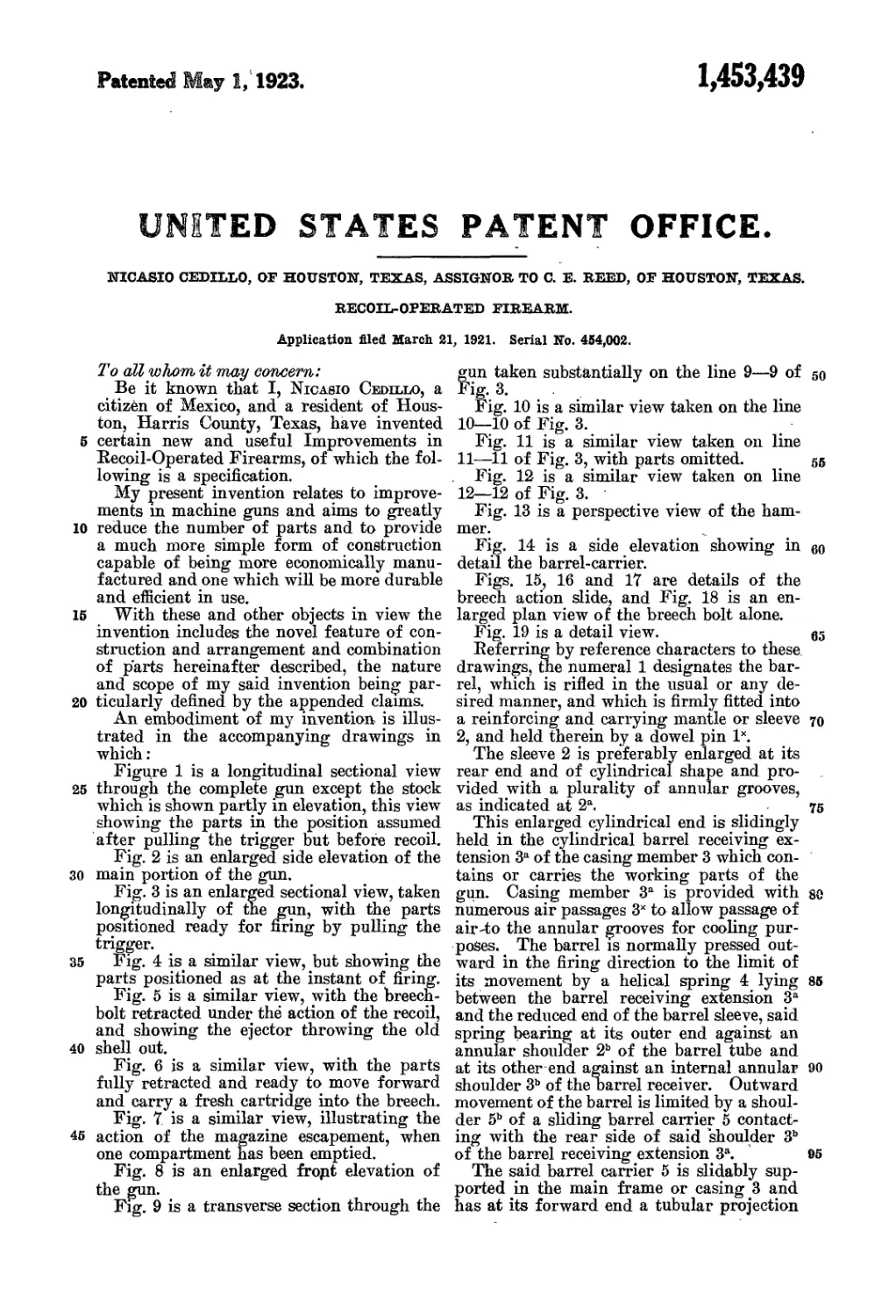
Patented May 1, 1923.
1,453,439
UNITED STATES PATENT OFFICE.
NICASIO CEDILLO, OF HOUSTON, TEXAS, ASSIGNOR TO С. E. REED, OF HOUSTON, TEXAS
RECOIL-OPERATED FIREARM.
Application filed March 21, 1921. Serial No. 454,002.
Tо all whom, it may concern:
Be it known that I, Nicasio Cedillo, a
citizen of Mexico, and a resident of Hous-
ton, Harris County, Texas, have invented
6 certain new and useful Improvements in
Recoil-Operated Firearms, of which the fol-
lowing is a specification.
My present invention relates to improve-
ments in machine guns and aims to greatly
10 reduce the number of parts and to provide
a much more simple form of construction
capable of being more economically manu-
factured and one which will be more durable
and efficient in use.
16 With these and other objects in view the
invention includes the novel feature of con-
struction and arrangement and combination
of parts hereinafter described, the nature
and scope of my said invention being par-
20 ticularly defined by the appended claims.
An embodiment of my invention is illus-
trated in the accompanying drawings in
which :
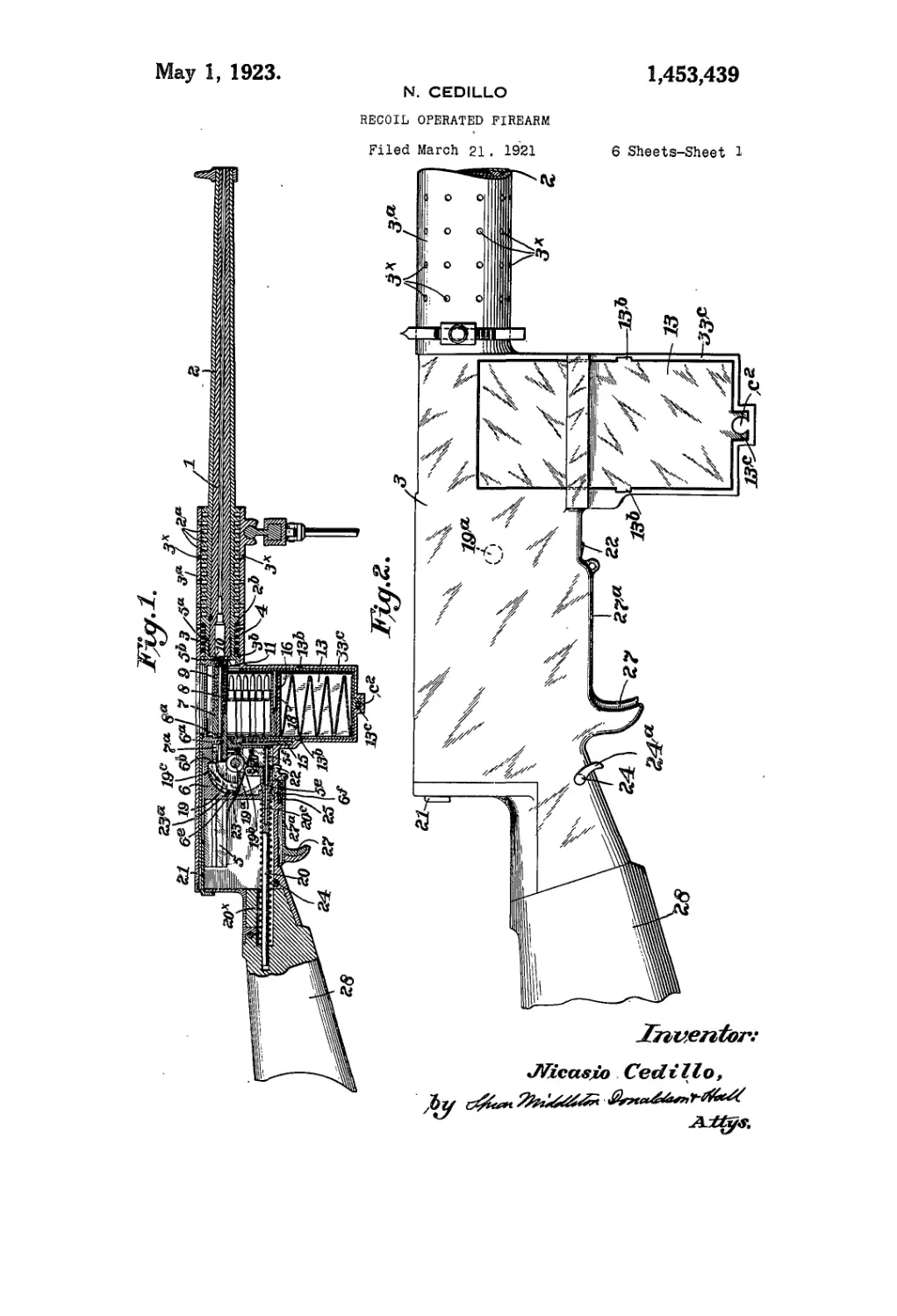
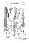
Figure 1 is a longitudinal sectional view
25 through the complete gun except the stock
which is shown partly in elevation, this view
showing the parts in the position assumed
after pulling the trigger but before recoil.
Fig. 2 is an enlarged side elevation of the
30 main portion of the gun.
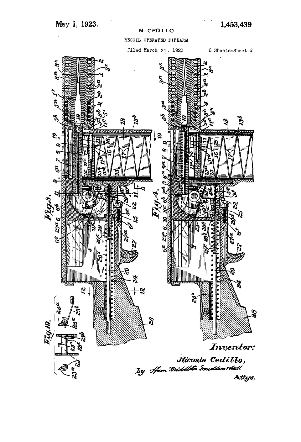
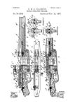
Fig. 3 is an enlarged sectional view, taken
longitudinally of the gun, with the parts
positioned ready for firing by pulling the
trigger.
35 Fig. 4 is a similar view, but showing the
parts positioned as at the instant of firing.
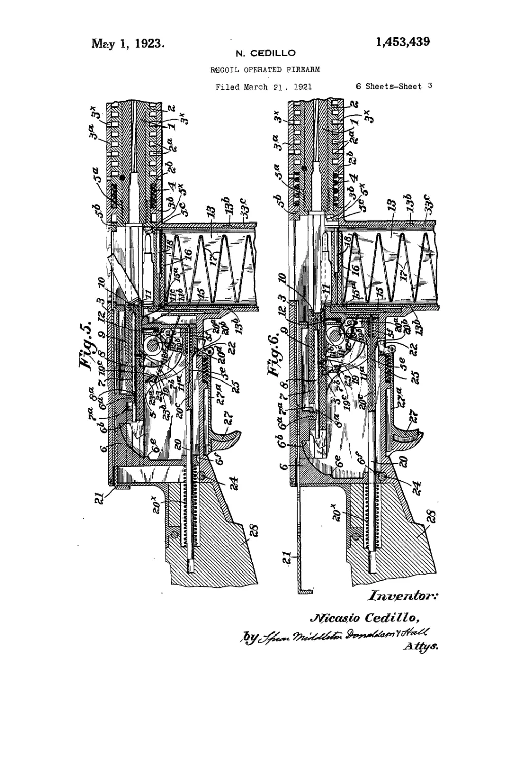
Fig. 5 is a similar view, with the breech-
bolt retracted under the action of the recoil,
and showing the ejector throwing the old
40 shell out.
Fig. 6 is a similar view, with the parts
fully retracted and ready to move forward
and carry a fresh cartridge into the breech.
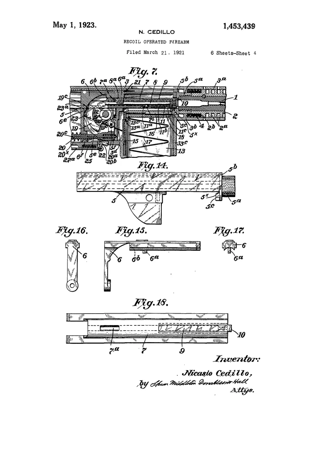
Fig. 7 is a similar view, illustrating the
45 action of the magazine escapement, when
one compartment has been emptied.
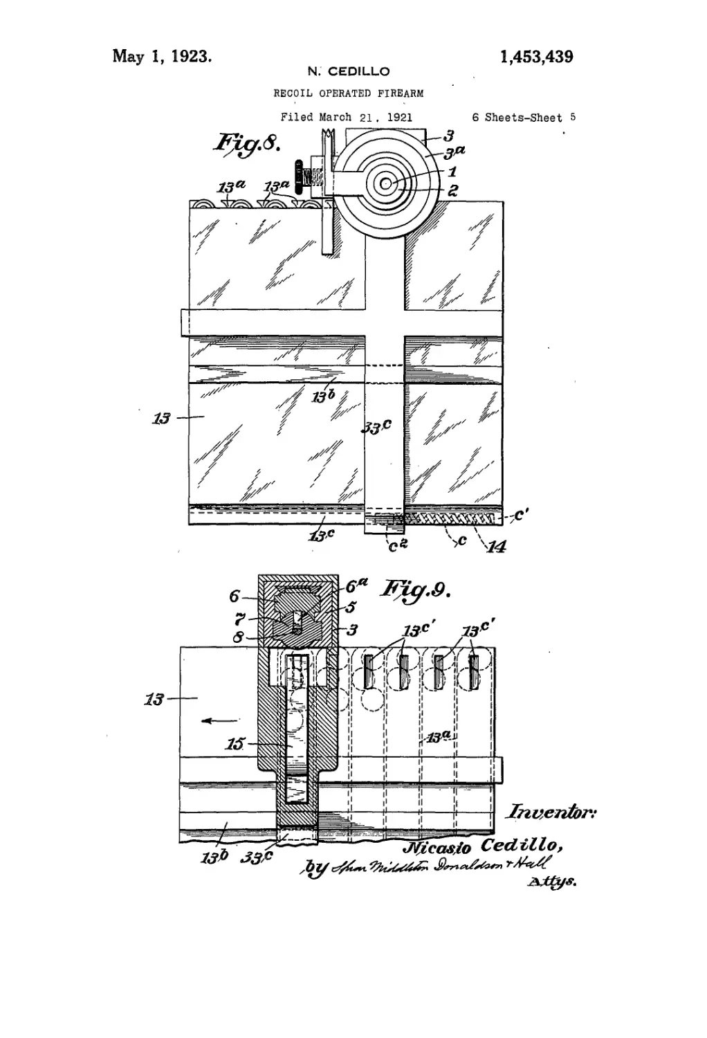
Fig. 8 is an enlarged fropt elevation of
the gun.
Fig. 9 is a transverse section through the
gun taken substantially on the line 9—9 of 50
Fig. 3.
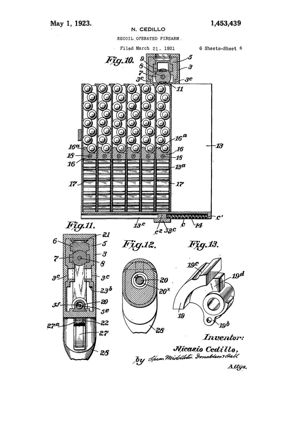
Fig. 10 is a similar view taken on the line
10—10 of Fig. 3.
Fig. 11 is a similar view taken on line
11—11 of Fig. 3, with parts omitted. 55
Fig. 12 is a similar view taken on line
12—12 of Fig. 3.
Fig. 13 is a perspective view of the ham-
mer.
Fig. 14 is a side elevation showing in eo
detail the barrel-carrier.
Figs. 15, 16 and 17 are details of the
breech action slide, and Fig. 18 is an en-
larged plan view of the breech bolt alone.
Fig. 19 is a detail view. eg
Referring by reference characters to these
drawings, the numeral 1 designates the bar-
rel, which is rifled in the usual or any de-
sired manner, and which is firmly fitted into
a reinforcing and carrying mantle or sleeve 70
2, and held therein by a dowel pin Iх.
The sleeve 2 is preferably enlarged at its
rear end and of cylindrical shape and pro-
vided with a plurality of annular grooves,
as indicated at 2a. 75
This enlarged cylindrical end is slidingly
held in the cylindrical barrel receiving ex-
tension 3a of the casing member 3 which con-
tains or carries the working parts of the
gun. Casing member 3a is provided with go
numerous air passages 3х to allow passage of
airdo the annular grooves for cooling pur-
poses. The barrel is normally pressed out-
ward in the firing direction to the limit of
its movement by a helical spring 4 lying 85
between the barrel receiving extension 3a
and the reduced end of the barrel sleeve, said
spring bearing at its outer end against an
annular shoulder 2b of the barrel tube and
at its other end against an internal annular 90
shoulder 3b of the barrel receiver. Outward
movement of the barrel is limited by a shoul-
der 5b of a sliding barrel carrier 5 contact-
ing with the rear side of said shoulder 3b
of the barrel receiving extension 3a. 95
The said barrel carrier 5 is slidably sup-
ported in the main frame or casing 3 and
has at its forward end a tubular projection
t
1,463,439
which is rigidly connected with the rear
id of the barrel, preferably by having said
id extended in rear of the barrel sleeve and
rovided with exterior screw-threads engag-
ig corresponding internal screw threads on
te tubular extension 5a.
The barrel carrier or receiver 5 is guided
> move in a rectilinear path in the casing
у being provided on opposite sides with
iternal longitudinal grooves or channels
hich are engaged by corresponding ribs or
Einges 3® formed on the inner walls of the
ising.
Slidably mounted within the barrel car-
er is a breech member or breech block 6
id a breech bolt 7 which have longitudinal
bs on their side faces which slidingly en-
ige corresponding guide grooves m the
met faces of the walls of the barrel carrier,
he breech member is cut away to receive
le hammer mechanism, hereinafter de-
:ribed into which cut away portions the
ps of the breech bolt 7 and firing pin 8
roject, the firing pin being slidably
lounted in the central longitudinal bore or
assage of the breech bolt.
A depending projection 6a from the upper
artion of the, breech member extends
irough an elongated opening or slot 7* in
ie’ wall of the breech bolt ana also engages
a elongated recess 8a of a different length
i the firing pin (constituting a lost motion
mnection) so that backward movement of
ie breech member will carry with it the
reech bolt and firing pin upon the projec-
on encountering the rear ends of the slots
г recesses in said parts.
Carried in a recess in the upper side of
ie breech bolt and projecting beyond the
id thereof is an extractor 9 having its for-
ard end shaped or hooked indicated at 10
> engage the rim of the cartridge.
On its under side the breech bolt is simi-
irly recessed or grooved to receive the
lector 11 which is mounted in said groove
>^as to have a sliding movement therein
mited by a projection T* on the breech
alt engaging a recess lla in the ejector,
ie forward end of the ejector normally
iaring against the heel of the cartridge.
The ejector is provided in its under face
ith an elongated recessed portion llb
hich terminates at its forward end in a
loulder IIе designed to cooperate with a
op device which comprises a pin 12 seated
i a vertical recess in the transverse wall
1 of the barrel receiver beneath the breech
olt and normally forced upward by a
iring 12®. The upper end of the stop pin
ears with a sliding contact on the under
de of the breech bolt and ejector, and in
ie backward movement of these parts,
iters the recess or groove llb and travels
jerein until it contacts with the shoulder
11е which causes the ejector to be held sta- 65
tionary while the breech bolt and extractor
continue their rearward movement, result-
ing in the ejection of the empty cartridge
shell.
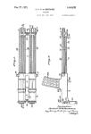
Fresh cartridges are supplied from a car- 70
tridge container 13 which is in the form of
a rectangular box open at its upper side
and divided by partitions 13a into a plu-
rality of cartridge containing compartments
of a width permitting the cartridges to lie 75
therein in staggered relation as shown. This
cartridge container is mounted to slide
transversely in an open frame member 33е
which forms preferably an integral part of
the casing 3. The container is properly 80
guided in the frame and prevented from
binding therein by guide ribs 13b on its
sides which engage corresponding grooves
in the sides of the frame, and by the bottom
rib 13е which engages a similar groove in 85
the bottom of the frame.
Rib 13е is provided in its under side with
a recess e of slightly more than semi-cylin-
drical form in cross-section within which is
located a spring 14 which abuts at one end 90
against ana is secured to a stop c' carried
by the container and at the other end against
a circular projection <? on the frame. The
spring 14 tends, when unrestrained, to move
the cartridge container to the right, Fig. 10,
so as to bring the cartridge containing com-
partments successively into loading posi-
tion as soon as a preceaing compartment has
been emptied, the said container being nor-
mally held stationary by a spring dog 15 loo
seated in a recess in the transverse wall of
the frame or casing and having its locking
end 15a adapted to engage a series of re-
cesses 13е' in the rear wall of the container.
The upper edges of the division walls 13*105
of the container are provided with over-1
hanging ledges which serve to retain the
cartridges in position in the compartments
due to the staggered relation hereinbefore
referred to. j no
Located in each compartment beneath the
cartridges therein, is a follower 16 which
is pressed upwardly by a spring 17, prefer-
ably of zigzag leaf form as shown, which ef-
fects delivery of the cartridges from the 115
compartment when in loading position, said
follower having an elevated portion 16* at
one side which tends to crowd the’lower-
most cartridge towards or position it in
proximity to the opposite wall of the com- 120
partment. Each follower has a longitudi-
nal bore or passage within which is located
a pin or transmitter 18 which normally and
when any cartridges are in the compart-
ment, lies with its ends in sliding contact 125
with the walls of the container, but which,
when the last cartridge has been ejected,
comes into line at its front end with the
1,468,489
S
б
10
15
г®
25
30
35
40
45
50
55
60
flange 5° and at its rear end with the lock-
ing projection 15“ of the dog or detent 15,
having a spring shank. Thereupon the
backward movement of the barrel or recoil
thereof forces the transmitter backward and
by its pressure removes the locking projec-
tion 15“ from engagement with the corre-
sponding recess in the container, which,
under pressure of its spring 14, is moved
to bring the next compartment into load-
ing position, whereupon said locking pro-
jection 15“ automatically engages the next
recsss to hold the container against further
movement. Flange 5C has an incline 5х to
direct the nose of the bullet into the barrel
chamber.
Within the barrel carrier 5 is located the
hammer 19 mounted to oscillate on piyot
pin 19“ and having a projection 19b which
engages by a pin and slot connection with a
pojection 20“ carried by the mainspring rod
20. The hammer has a reduced or web like
portion 19a, and the breech bolt, lips or pro-
jection 7a, which overlap said web when
the breech bolt is in locked position,
(Fig. 4.)
The main spring rod passes through an
opening in the rear wall of the breech block
and has a shoulder 20b cooperating with
the front wall thereof, while the portion of
the main spring rod which projects through
the rear wall of the breech block is encircled
by main spring 20х which is secured in a
recess in the stock and bears against the rear
wall of the breech block. The main spring
rod has a longitudinal bore 20е extending
backward from its front end, within which
bore is slidingly fitted a rod. 5е fast at its
front end to the transverse wall 5a of the
barrel receiver. ^Encircling this rod between
said wall 5a and the main spring rod is a
helical compression spring 5f, and the for-
ward end of the main spring rod is pref-
erably provided with a countersink or an-
nular rebate to make provision for a longer
spring than could otherwise be secured, this
spring serving to actuate the hammer to
fire the cartridge.
Backard movement imparted to the breech
block, either under the impact of the barrel
receiver in firing, or the hand action slide
21, effects the cocking of the hammer due to
the action of the shoulder 6b of the breech
block and the rear end of the breech bolt on
the forward and preferably stepped face of
the hammer, which hammer is of segmental
shape as shown.
This rocks the hammer on its pivot in the
direction of the arrow, Fig. 1, and causes
the arm 19b to move rod 20 forward com-
pressing hammer spring 5f until the trigger
22 engages behind shoulder 20a of rod 20
and locks the trigger in cocked position, in
which position it is locked by automatic
lock 23 which is in the shape of a rotary e6
pin having a flat side 23е designed to be .
pressed upon by spring 23b, this pin engag-
ing a curved recess 19° in the outer surface
of the hammer, this lock being automatically
unlocked on forward movement of the breech 70
block by a projection 6е on the latter engag-
ing a projection 23“ on the locking pin.
The breech block may be locked in its re-
tracted position by rotary locking pin 24
cooperating with locking recess 6f of the 75
breech block, the said pin 24 being operated
by hand, by the trigger end or handle 24a.
The trigger is acted upon by spring 25
and is actuated by trigger ward 27 connected
thereto by bar 27“. 80
The usual stock is indicated at 28, and the
gun in practice would be provided with cus-
tomary front and rear sights and tripod
connection.
It is believed that from the foregoing the ss
construction and operation of my improved
gun will be clear, it being of course, under-
stood that the gun will continue to fire auto-
matically as long as the finger is held pressed
upon the trigger ward, but will stop instant- 00
ly upon such release as is customary.
Having thus described my invention, what
I claim is:
1. A machine gun comprising a casing,
a barrel carrier carried thereby to be mov- 95
able under recoil, a breech bolt slidably car-
ried by said barrel carrier and having a
central firing pin, an extractor carried by
the upper part of said breech bolt, an ejector
carried by the lower part to have limited 100
sliding movement, and a contact device car-
ried by the barrel carrier coacting with a
lug on the ejector to project the latter, be-
yond the breech bolt.
2. A machine gun comprising a casing, 105
a barrel carrier carried thereby to be mov-
able under recoil, a breech bolt slidably car-
ried by said barrel carrier and having a
central firing pin, an extractor carried by
the upper part of said breech bolt, an ejector no
carried by the lower part to have limited
sliding movement, said ejector having an
elongated recess in its under surface ter-
minating in an abrupt shoulder at its for-
ward end, and a projectable contact device 115
carried by the barrel carrier for coaction
with said .shoulder.
3. A machine gun comprising a casing,
a barrel carrier carried thereby to be mov-
able under recoil, a breech bolt slidably car- 120
ried by- said barrel carrier and having a
central firing pin, an extractor carried by
the upper part of said breech bolt, an ejector
carried by'the lower part to have limited
sliding movement, said ejector having an 125
elongated recess in its under face ter-
minating in an abrupt shoulder, a slidable
pin seated in a recess in the barrel carrier
1,463,430
d adapted to enter said recess and coop-
ite with said shoulder, and a spring in
id recess acting on said pin.
1. In a machine, a main casing, a barrel
rrier movable therein under recoil, a bar-
rigidly connected to said barrel carrier,
jreech block and breech bolt supported by
id barrel carrier, said breech bolt having
central passage, a firing pin therein, said
eech bolt and firing pin having aligning
mgated slots or recesses, and said breech
ick having a part projecting into both
id slots or recesses.
5. In a machine gun, a main casing, a
rrel carrier slidably guided therein, a
aech bolt slidably guided in said carrier
d carrying a firing pin, a breech, block
dably carried in said casing, said breech
>ck having a lost motion connection with
th said breech bolt and firing pin and hav-
» also a shoulder adjacent the rear end of
i breech bolt and a hammer having face
rtions overlying said shoulder and the
tr end of the breech block.
6. In a machine gun, a main casing, a
rrel carrier slidably guided therein, a
sech bolt slidably guided in said carrier
d carrying a firing pin, a breech block
dably carried in said casing, said breech
>ck having a lost motion connection with
th said breech bolt and firing pin and hav-
* also a shoulder offset in rear of the rear
d of the breech bolt, and a hammer hav*
? a stepped face cooperating with said
milder and breech bolt end.
Г. In a machine gun, a main casing, a
rrel carrier slidably guided therein, a
sech bolt slidably guided in said carrier
d having a central longitudinal passage,
iring pin located in said passage, a breech
>ck slidably guided in said carrier and
ving a part overlying the breech bolt, said
sech bolt and firing pin having aligning
lesses of different lengths and said over-
ng part a projection extending into said
messes, said breech block having a shoulder
set in rear of the tear end of the breech
It, and a hammer having a stepped face
iperating with said shoulder and breech
It end.
3. In a machine gun, a main casing, a
rrel carrier slidably guided in said cas-
*, a breech bolt and firing pin slidably
ided by said carrier, a breech block hav-
r a lost motion connection with said breech
It and firing pin, a hammer pivotally car-
d by said barrel carrier and having a part
: coacting with said breech bolt and fir-
r pin, and a spring acting on said ham-
r.
J. In a machine gun, a main casing, a
rrel carrier slidably guided therein, a
sech bolt and firing pin slidably mounted
said carrier, a breech block also slidably
mounted in said carrier, a main spring ex-
erting forward pressure on said breech
block,, a hammer articulated to said carrier,
an arm or projection depending from the
hammer, a slidable member having a part
connected to said hammer arm, a spring ex-
erting rearward pressure on said slidable
member, and trigger mechanism cooperating
with said slidable member.
10. In a machine gun, a main casing, a
barrel carrier slidably guided therein, a
breech bolt and firing pin slidably mounted
in said carrier, a breech block also slidably
mounted in said carrier, a main spring ex-
erting forward pressure on. said breech
block, a hammer articulated to said carrier,
manually operated locking means for hold-
ing said breech block in retracted position,
an arm or projection depending from the
hammer, a slidable member having a part
connected to said hammer arm, a spring ex-
erting rearward pressure on said slidable
member, and trigger mechanism cooperating
with said slidame member.
11. In a machine gun, a main casing, a
barrel carrier slidably guided therein, a
breech bolt and firing pin slidably mounted
in said carrier, a breech block also slidably
mounted in said carrier, a hammer articu-
lated to said carrier, a slidable rod guided
in the casing and extending through an
opening in the breech block, the forward
end of said rod having an actuating con-
nection with said hammer, a spring inter-
posed between the front end of said rod and
a part of the barrel carrier, a trigger mech-
anism cooperating with a part carried by
said rod, and a spring exerting forward
pressure op said breech block.
12. In a machine gun, a main casing, a
barrel carrier slidably guided therein, a
breech bolt and firing pin slidably mounted
in said carrier, a breecn block also slidably
mounted in said carrier, a hammer articu-
lated to said carrier, a slidable rod guided
in the casing and extending through an
opening in the breech block, the forward
end of said rod having an actuating connec-
tion with said hammer, a spring interposed
between the front" end of said rod and a part
of the barrel carrier, a trigger mechanism
cooperating with a part carried by said rod,
and a helical spring encircling said rod and
exerting forward pressure on the breech
block.
13. In a machine gun, a main casing, a
barrel carrier slidably guided therein, a
breech bolt and firing pin slidably mounted
in said carrier, a breech block also slidably
mounted in said carrier, adiammer articu-
lated to said carrier, a slidable rod guided
in the casing and extending through an
opening in the breech block, the forward
end of said rod having an actuating con-
es
70
П
80
86
90
95
100
105
110
115
120
125
1,463,439 Д
nection with said hammer, said rod having
a tubular front end, a second rod connected
to a part on the carrier and slidably engag-
ing said recess, a compression spring en-
5 circling said second rod, and trigger mecha-
nism coacting with said first named rod.
14. In a machine gun, a main casing, a
barrel carrier slidably guided therein, a
breech bolt and firing pin slidably carried
by said carrier, a breech block slidably car- io
ried in said carrier, a hammer articulated to
said carrier, an automatic lock for holding
said hammer, and means on the breech block
for automatically unlocking said hammer.
In testimony whereof, I affix my signa- 15
ture.
NICASIO CEDILLO.