/
Tags: weapons military affairs patent
Year: 1895
Text
2. Sheets—Sheet 1.
(No Model.)
No. 547,454.
L. SCHMEISSER.
RECOIL OPERATED FIREARM.
Patented Oct. 8, 1895.
2 Sheets—Sheet 2.
{No Modfel.)
L. SCHMEISSER.
RECOIL OPERATED JIREARM.
No. 547,454.
Patented Oct. 8, 1895.
United States Patent Office.
LOUIS SCHMEISSER, OF MANNHEIM, ASSIGNOR TO THEODOR BERGMANN, OF
jGAGGENAU, GERMANY.
& • .
RECOIL-OPERATED FIREARM.
SPECIFICATION forming part of Letters Patent No. 647,454, dated October 8,1896.
Application filed January 20,1804. Serial Ko. 487,523. (No model.) Patented in France June 8,1893, No. 230,689; in Germany
June 10,1893, No. 78,500, and February 13, 1894, No. 78/8811 in England June 12,1893, No. 11,509 ? in Italy June 30,
1893, No, 34,238। in Belgium October 31, 1893, No. 108,826, and Hay 15, 1894, No. 109,8291 in Switzerland December 6,
1893, No, 7,2011 in Austria Hay 31,1894, No. 44/2,000, and in Hungary June 26,1894, No. 678.
To all whom it may concern:
Be it known that I, Louis Schmeissek, gun-
maker, a citizen of Germany,residing at Mann-
heim, in the Grand Duchy of Baden, Em-
5 pire of Germany, have invented certain new
and useful Improvements in Breech-Loading
Firearms, of which the following is a specifi-
cation.
The invention has been patented in Ger-
то many, No. 78,500, dated June 10,1893, and
No. 78,881, dated February 13, 1894; in Aus-
tria, No. 44/2,000, dated May 31, 1894; in
Hungary, No. C78, dated June 26, 1894; in
Switzerland, No. 7,201, dated December 6,
<5 1893; in France, No. 230,689, dated June 8,
1893; in England, No. 11,509, dated June 12,
1893; in Belgium, No. 106,826, dated October
31,1893, and No. 109,829, dated May 15,1894,
and in Italy, No. 34,238, dated June 30,1893.
го My invention relates to a firearm in which
the closing of the breech, the loading, and the
- cocking of the hammer is effected by the gas-
pressure resulting from the explosion. It has
been usual heretofore to oppose a resistance
25 as strong as possible to the pressure of the
gases from the rear or closing parts, so that
said gas, after having yielded all its useful-
ness, could only escape through the front part.
If the resistance is very great the breech is
30. opened either by hand or mechanically after
. each shot, and if slight, as in this class of arms,
it is opened or loosened by the pressure of the
gas and bolted or closed again by hand by a
special mechanism or automatically. In the
35 improved system of breech-closing this resist-
ance is made away with entirely, as the same
is based upon an entirely different principle,
to wit: the principle of the power of resist-
ance of bodies. The explosion of the powder
4.0 produces a pressure of gas in the cartridge or
shell which works uniformly against all sides.
According to the laws governing the power of
resistance the smallest movable part that is
exposed to that pressure will be put in motion
45 the first. A breech-bolt bearing against the
rear end of the barrel, the weight of which is
a certain multiple of that of the projectile, is
given a motion by the gas-pressnre which is
correspondingly slower than the lighter pro-
jectile. If now the proportion between the 50
weight of the breech-bolt and that of the pro-
jectile is such that up to the time that said
projectile leaves the barrel the breech-bolt
has been driven back only a short way, thoro
will be no loss of the driving power of the gas, 55
as the slowly backward moving breech-bolt,
in combination with the shell pressed against
its bearing, will produce a perfectly gas-tight
closure at the rear. The further backward
motion of the cylinder serves for reloading 60
of the firearm and for the compression of a
spring, which brings the breech-bolt again in
the closing position after it has reached its
utmost rear point, and the arm is ready to bo
used again. 65
In the annexed drawings two forms of con-
struction of the auto-loading arm with tho
new breech-loading device are shown. •'
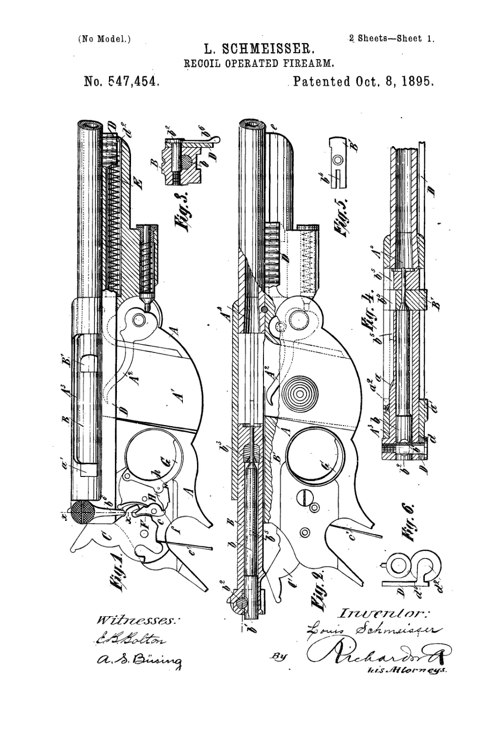
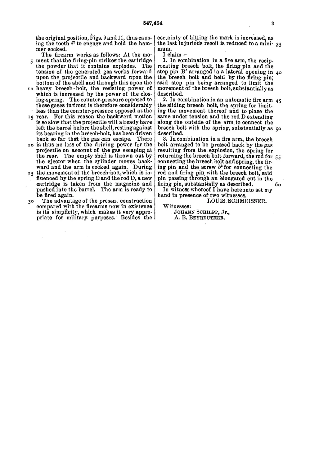
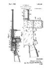
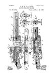
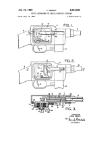
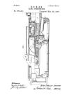
Figure 1 is a side view of the arm, partly in
section, with the breech closed. Fig. 2 is a 70
side view with the breech-bolt and adjacent
parts in section, said breech-bolt being drawn
back. Fig. 3 is a sectional view on the line
X X of Fig. 1. Fig. 4 shows a horizontal sec-
tion through the breech-bolt and frame. Figs. 75
5 and 8 are details of the same. Fig. 6 is a
detail view of the muzzle of the barrel and of
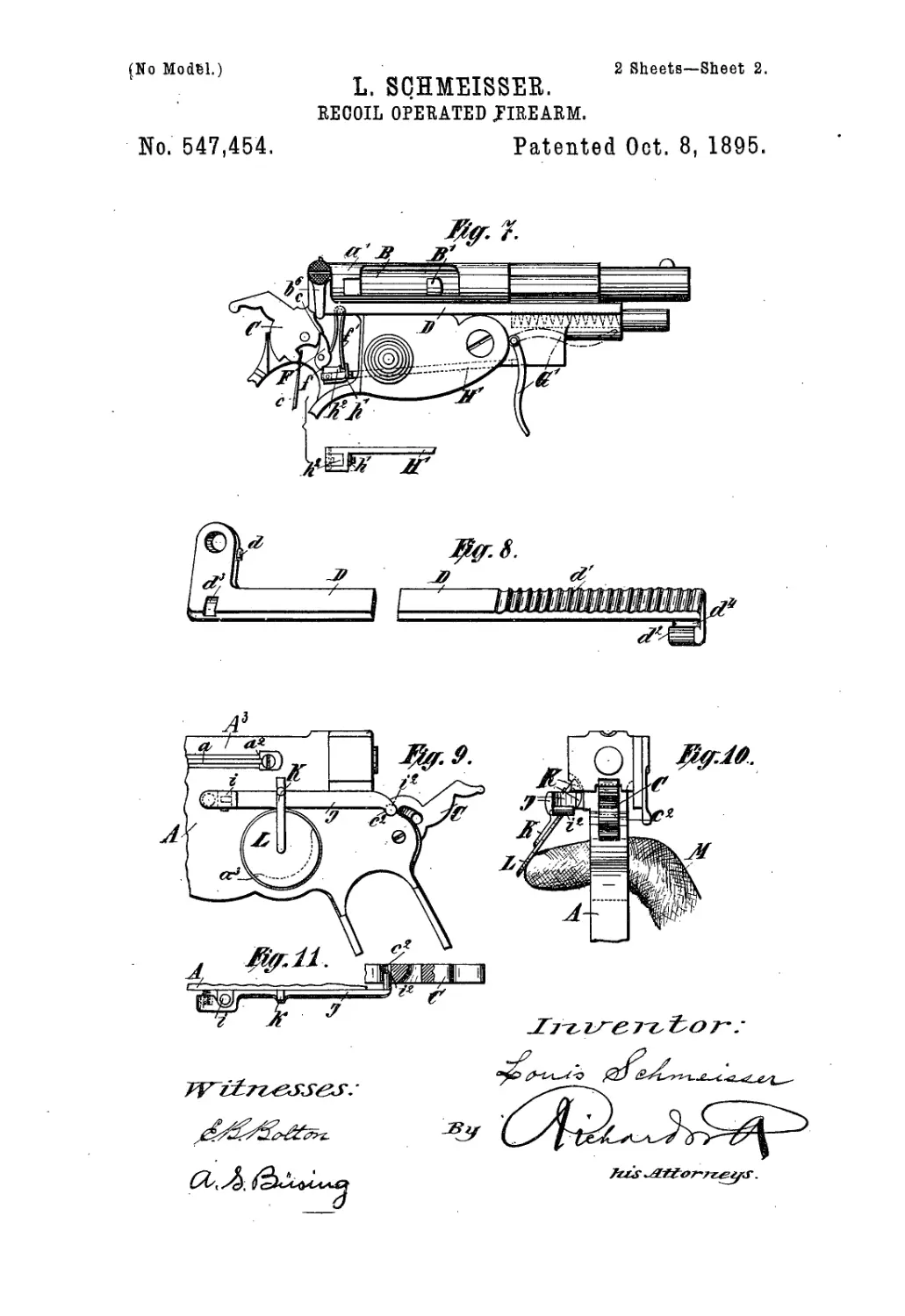
the frame of the spring. Fig. 7 is a side view
of a small hand-arm. Figs. 9,10, and 11 are
detail views of a safety-trigger. . 80
In the frame A, to which the barrel is fas-
tened and upon which the cartridge-magazine
A' is disposed, the breeeh-bolt В can move in
a straight line within certain limits. Tho
frame A is cut out vertically and to the right, 85
so that the cartridges can be carried directly
into the barrel and that the shells can bo
thrown out. The cartridges can be put into
the magazine A* one by one or by moans of a
loading-box. A spring-lover A2 presses the 90
cartridges against the breech-bolt frame A:1,
so that each time the breceh-bolt В advances
one cartridge is pressed into the cartridge-
seat A4. The firing-pin b, it will be noticed,
is not worked by a spring. It is located within 95
the breeeh-bolt. For Central percussion-car-
tridges it is located in tho center, and for car-
tridges having the percussion at the edge it
647,464
is located at the edge. - The pin b can slightly
move axially in the bolt B, but its dropping
out is prevented by a pin b\ Figs. 2, 3, and
,4, engaging a cut b' of the pin b and screwed
in the rear extremity of the breech-bolt.
Near,its forward extremity the breech-bolt В
has a cross-bore b3, in which the striking-peg
B', Figs. 1, 2, 4, and 5, is arranged loosely.
The pin b passes through the striking-peg B',
so that the latter is prevented from moving
in the cylinder B. The sjop-pin has a groove
b4, through which the ejection-bar a, Figs. 2
and 4, located at the rear wall of the frame,
passes. The breech-bolt В is provided with
a similar groove, in which the forward part
of the bar a moves. The shell, which is driven
’ back with the breech-bolt В by the gas result-
ing from the explosion, hits the nose of the ejec-
tion-bar a and is ejected in the well-known
, manner. When the bolt В moves backward,
the extremity of the pin B', that projects to
one side of the bolt, strikes the frame A? at a'
and limits the backward motion of the bolt.;
Thebreech-bolt B,that by its backward motion
; has cocked the hammer C again, is connected
loosely with a spring E, located under the
barrel in the body of the pistol, by means of
an outside -rod D, Figs. 1, 2, 3, 4, 6, and 8,
which spring carries back the breech-bolt to
a the closing position, of Fig. 1. As the ham-
mer C, as well as the spring E, increases the
. resisting power of the breech-bolt, the weight
of the latter can be somewhat reduced.. The
screw-bolt b\ with its leaf b*, serves for con*
5 necting the rod D with the bolt B. ’ Therefore,
in order to remove the' breech-bolt it is only
necessary to loosen the screw b3, whereby the
firing-pin b becomes free also. In order to
retain the dosing-spring rod D in the right
о position where the breech-bolt is removed, the
same is provided with a cam that engages in a
corresponding groove of the cylinder-frame A8.
d' is a roughened surface disposed upon the
rod D, which gi ves a better hold for the hand
5 when it is required.to keep the cylinder in the
open position, Fig. 2.
d3 is a calk disposed kt the side of the rod
D/opon which the spring E works, and d*isa
rest for the leaf b8 of the screw b3. The frame
о of the spring E has a side dot e, in which the
stay d4, between the rod D and the calk d3,
Figs. 6 and 8, can slide. ,
The firearm is-provided with a spring or
cock-lock which differs only as far aS the trig-
5 ger apparatus is concerned from' the usual
constrnction.
It is a well-known fact that in auto-loading
firearms the hammer is cocked so soon after
the explosion that the finger cannot let the
:o trigger go back quickly enough and that the
disengaged sear F cannot catch in time into
the top notch c of the hammer to hold it
cocked. In order to insure engagement of the
sear F in the top notch c, even if the finger
55 still rests upon the trigger, an intermediate
piece II, worked by a spring; Is placed between ,
the sear F and the trigger G in such a man-
ner that the connection between F and G can
be interrupted for a moment. When the ham-
Дпег C is cocked, the sear F engages in the top .70
notch c. If now the trigger G is pulled the
intermediate piece H, that is revolubly con-
nected therewith, presses upon the tooth/of
the sear F and lifts the latter from the top
notch c,so that the hammer C, inconsequence 75
of the working of the spring c’ upon the same,
drives the firing-pin forward. As the cock-
ing of the hammer follows immediately after
the explosion and before the finger can release
the trigger, the construction is such that as 80.
soon as the sear F is disengaged the intermedi-,
ate piece slides over the tooth / and the ham-
mer can bo cocked without working the trig-
ger. When now the finger releases the trig-
ger, the piecell returns to its original position 85
by means of the spring h, after which the
trigger is ready for another shot.
In small firearms the trigger may be ar->
ranged to be pushed forward, as shown in
Fig. 7. In this case the intermediate piece is 90
changed into a rail H', upon the head of
which the trigger G' presses. The latter can
be pnt in position (shown by dotted lines in
Fig. 7) for the sake of carrying the arm con-
veniently. At the rear end of the rail H' a 95
presser A3 is pivotally disposed, which is kept
in its normal position, as shown in Fig. 7, by
the spring A'. After the presser A3 has dis-
engaged the Sear F it glides over the tqoth of
the same, So that the sear F can at once catch 100
again into the top notch of the cock. After
the finger has released the trigger the rod-
spring A' brings the rail H' back again in its
original position. As soon as the presser A8
has passed nhder the cam /, a spring A' car- 105
ries it back again to its normal position, and
the arm is ready to be shot off again.
In order to prevent the hammer C from op-
erating prematurely, the firearm is provided
with a trigger-safety, Figs. 9 to 11. A lever но
I, that dan revolve around a hinge i, is placed
upon, the back wall of the frame A.. A spi-
ral spring i’i that works upon the smaller arm
of this lever, tends to push it away from the
frame A. The longer arm of the lever I. car- 115
ries a tooth i3, to catch into an opening c3 in
the hammer C, so that it can hold the same
in its cocked position. In the lever I another
lever К iS pivotally arranged, which carries a
disk L, which rests upon the opening a* of the 120
frame in the position Of rest. When the An-
ger is brought into the trigger-guard, the disk
L is pushed Aside and the lever К is pressed
against* the frame A. The consequence of
this is that the longer arm of the lever I is 125
pushed away from the frame and the tooth i3.
is released from the slot c3 of the cock C, Fig.
10. The safety device is thus thrown out of
action and the hammer can fall when the
trigger is pressed. As soon as the finger is re- 130
moved from the trigger-opening a8, the spring
1 i’ carries the lever I and the disk L '.gain to
647,454
3
the original position, Figs. 9 and 11, thus caus-
ing the tooth, i2 to engage and hold the ham-
mer cocked.
The firearm works as follows: At the mo-
5 ment that the firing-pin strikes the cartridge
the powder that it contains explodes. The
tension of the generated gas works forward
upon the projectile and backward upon the
bottom of the shell and through this upon the
to heavy breech-bolt, the resisting power of
which is increased by the power of the clos-
ing-spring. The counter-pressure opposed to
those gases iufront is therefore considerably
less than the counter-pressure opposed at the
15 rear. For this reason the backward motion
is so slow that the projectile will already have
left the barrel before the shell, restingagainst
its bearing in the breech-bolt, has been driven
back so far thett the gas can escape. There
20 is thus no loss of the driving power for the
projectile on account of the gas escaping at
the rear. The empty shell is thrown out by
the ejector when the cylinder moves back-
ward and the arm is cocked again. During
25 the movement of the breech-bo It, which is in-
fluenced by the spring E and the rod D, a new
cartridge is taken from the magazine and
pushed into the barrel. The arm is ready to
be fired again.
30 The advantage of the present construction
compared with the firearms now in existence
is its simplicity, which makes it very appro-
priate for military purposes. Besides the
certainty of hitting the mark is increased, as
the last injurious recoil is reduced to a mini- 35
mum.
I claim—
1. In combination in a fire arm, the recip-
rocating breech bolt, the firing pin and the
stop pin B' arranged in a lateral opening in 40
the breech bolt and held by the firing pin;
said stop pin being arranged to limit the
movement of the breech bolt, substantially as
described.
2. In combination in an antomatic firearm 45
the sliding breech bolt, the spring for limit-
ing the movement thereof and to place the
same under tension and the rod D extending
along the outside of the arm to connect the
breech bolt with the spring, substantially as 50
described.
3. In combination in a fire arm, the breech
bolt arranged to be pressed back by the gas
resulting from the explosion, the spring for
returning the breech bolt forward, the rod for 55
connecting the breech bolt and spring, the fir-
ing pin and the screw b’ for connecting the
rod and firing pin with the breech bolt, said
pin passing through an elongated cut in the
firing pin, substantially as described. 60
In witness whereof I have hereunto set my
hand in presence of two witnesses.
LOUIS SCIIMEISSER.
Witnesses:
Johann Schilpp, Jr.,
A. B. Beyeeuthee.