/


Tags: weapons military affairs patent
Year: 1967

Text
Sept. 26, 1967
H. MENNEK1NG ETAL
3,343,457
HOUSING STRUCTURE FOR AN AUTOMATIC FIREARM
2 Sheets-Sheet 1
Filed Dec. 10, 1965
Inventors
Л&ГС'ТП ut Me'n'ne.kcTig
Негтп.я--П77 He~n~n
Sept. 26, 1967 н. menneking etal 3,343,457
HOUSING STRUCTURE FOR AN AUTOMATIC FIREARM
Filed Dec. 10, 1965 2 Sheets-Sheet 2
,, , , Inventors
г&гЦтсЛ r/<£ T77?&/(Ln<3
A 777^ 77 77 H&~77 77 C77J
A t tys.
United States Patent Office
3,343,457
Patented Sept. 26, 1967
1
3,343,457
HOUSING STRUCTURE FOR AN
AUTOMATIC FIREARM
Hartmut Menneking and Hermann Henning, Dusseldorf,
Germany, assignors to Firma Rheinmetall G.m.b.H.,
Dusseldorf, Germany
Filed Dec. 10, 1965, Ser. No. 512,901
Claims priority, application Germany, Dec. 19, 1964,
R 39,504
5 Claims. (Cl. 89—199)
ABSTRACT OF THE DISCLOSURE
An automatic firearm having a breechblock housing
consisting of two mirror-image halves forming similar
guide tracks for a breech and semi-cylindrical shell halves
at the front ends of the housing halves to receive a barrel
of tlie firearm with a sleeve surrounding the shell halves
and tension means and a locking member to maintain the
two mirror-image halves together.
The invention relates to automatic firearms, for ex-
ample automatic cannons. In such weapons, which are fre-
quently installed in vehicles, tank or armoured turrets and
aircraft, dimensions and weight are generally of great,
and frequently even decisive, importance, since the space
available for installation is often limited. Moreover, the
manufacture of the gun housing of automatic cannons
generally involves very complicated and extensive ma-
chining work on large blocks of metal, so that high pro-
duction costs result.
The object of the present invention is the provision of
an automatic weapon, in particular an automatic cannon,
which is economical to make, requires a comparatively
small space for installation and is capable of rapid instal-
lation which can be carried out with simple tools.
An automatic weapon according to the invention has
a housing divided in a vertical longitudinal central plane
into two halves, the front ends of which receive the bar-
rel of the weapon in such a manner that the barrel can be
interchanged, the halves being held together by clamping
means.
The relatively small dimensions which it is possible to
obtain make a compact construction of the weapon
housing possible. The halves of the housing may advan-
tageously consist of drop forgings and in this way, ex-
tensive and costly milling work which is always neces-
sary in the conventional method of manufacture is dis-
pensed with, since the housing halves forged in a die
require only simple and relatively little machining, in par-
ticular only the fitting and guide surfaces need ma-
chining.
The front end of the weapon housing which receives
the barrel of the weapon advantageously consists of semi-
cylindrical shell halves of the halves of the housing, which
are clamped in a sleeve tightly embracing the shell halves.
The sleeve may be shrunk on over the shell halves having
been previously heated. The sleeve may advantageously
also contain the necessary structural elements for receiving
the breechblock drive, a closing spring housing and other
elements.
If a weapon embodying the invention is intended to be
gas-operated, then the bores and ducts required for the
gas operation may advantageously be provided in the wall
of the sleeve embracing the shell halves.
As a subsidiary feature of the invention, the halves
of the housing are connected to one another by means
of tension rods which assist in resisting transverse forces
originating during firing in the region of the locking means
for the breechblock. The tension rods may be shrunk
2
into place having been previously heated. In this way,
an extremely rigid and compact construction is obtained,
in conjunction with a comparatively small width of the
weapon housing in the region of the locking means for the
5 breechblock.
A further desirable subsidiary feature of a weapon
housing embodying the invention is the connection to-
gether of the rear ends of the halves of the housing by a
locking member suitable for taking up longitudinal and
10 transverse forces and which is advantageously in the form
of a hollow body which may also accommodate a buffer
device.
An embodiment of the invention will now be described
in greater detail with reference to the accompanying
15 drawings of which:
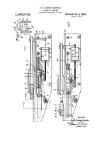
FIG. 1 is a section on the line I—I of FIG. 2 of a gas-
operated automatic cannon embodying the invention,
FIG. 2 is a plan view thereof,
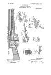
FIGS. 3 and 4 are cross-sections on the lines III—III
20 and IV—IV of FIG. 1,
FIG. 5 is a section on the line V—V in FIG. 1, and
FIG. 6 is a section on the line VI—VI of FIG. 5.
The housing of the cannon is divided in the vertical
longitudinal central plane of the weapon and consists of
25 two mirror-image housing halves 1 and 1' which have
semi-cylindrical shell halves 2 and 2', respectively, at
their front ends, i.e. the left-hand ends as seen in FIG. 1.
The shell halves 2 and 2' receive the barrel of the weapon
and are tightly clamped in a sleeve 4 which is shrunk
30 on to the shell halves by heating it prior to installation on
the shell halves. The shell halves receive the barrel 3
of the weapon and are formed in known manner with
ridge-like teeth 5 which engage corresponding teeth on
the barrel and hold the shell halves in position whilst per-
35 mitting easy interchange of barrels when necessary.
Ducts 6 and bores 7 for a breechblock of the weapon
actuated by the gas pressure and for an ammunition feed
means (not shown) likewise operated by the gas pressure
are provided in the wall of the sleeve 4. The sleeve 4 also
40 supports a closing spring housing 8, which is fixed to
the sleeve by means of screws. In addition, other structural
elements may be provided on the sleeve, for example for
holding ammunition feed means, this, however, not being
shown in the drawing for the sake of clarity.
45 When automatic cannons are fired, considerable forces
directed transversely of the axis of the bore frequently
occur in the region of the locking means of the breech-
block. In order to resist such transverse forces, the halves
of the housing are connected to one another by tension
60 rods or anchors 9, which are let into corresponding re-
cesses 10 in the halves of the housing.
At the rear end of the housing is located a locking
member 11 in the form of a hollow body which embraces
the rear edges 13 and 13' of the halves of the housing by
55 means of two ridges 12 and 12' respectively. The locking
member 11 serves also as a housing for a buffer device.
The buffer forces acting in the longitudinal direction are
transmitted to the halves 1 and 1' of the housing by way
of shoulders 14, 14' provided on the locking member.
60 The halves 1 and 1' of the housing are drop-forged
workpieces, in which only the fitting and guide surfaces
marked a, b, c, d in the drawing and those surfaces which
serve to receive the locking member 11 require machining.
We claim:
65 1. An automatic firearm comprising a breechblock
housing consisting of two mirror-image halves as similar
guide tracks for a breechblock, semi-cylindrical shell
halves at front ends of the housing halves to receive a
barrel of the firearm, a sleeve surrounding the shell
halves and which has a bore to tightly receive the shell
halves, tension means provided around one end of the two
3,343,457
3
mirror-image halves, and a locking member at the other
end of the two mirror-image halves and having ridges
which interfit with the other end of the two mirror-image
halves, said locking member being adapted to reecive a
buffer device.
2. An automatic firearm according to claim 1, in which
means are provided in the locking member to provide
shoulders for the two mirror-image halves.
3. An automatic firearm as claimed in claim 1 and
further comprising a breechblock drive, and a return
spring housing accommodated in said sleeve.
4. An automatic firearm as claimed in claim 1 and
further comprising bores and ducts forming part of gas-
operated power means, said bores and ducts being located
in the wall of said sleeve.
5. An automatic firearm as claimed in claim 1 in which
4
said sleeve is mounted upon the housing halves and then
shrunk into position.
References Cited
UNITED STATES PATENTS
1,290,855 1/1919 Wesson 42—75 X
1,401,667 12/1921 Brown.
3,009,396 11/1961 Dixon 89—191
3,282,166 11/1966 Maillard 89—191
10 3,289,535 12/1966 Hupp 89—191
FOREIGN PATENTS
749,430 5/1956 Great Britain.
BENIAMIN A. BORCHELT, Primary Examiner.
S. C. BENTLEY, Assistant Examiner.