/


Tags: weapons military affairs machine gun patent
Year: 1948
Text
March 2, 1948. f. i. rataiczak 2,436,937
SHELL EJECTING MECHANISM FOR MACHINE GUNS
Filed May 23, 1945 z 2 Sheets-Sheet 1
FIG. 2
March 2, 1948. f. j. rataiczak 2,436,937
SHELL EJECTING MECHANISM FOR MACHINE GUNS
Filed May 23, 1945 2 Sheets-Sheet 2
Patented Mar. 2, 1948
2,436,937
UNITED STATES PATENT OFFICE
2,438,937
SHELL EJECTING MECHANISM FOR
MACHINE GUNS
Francis I. Rataiczak, Dayton, Ohio, assignor to
General Motors Corporation, Dayton, Ohio, a
corporation of Delaware
Application May 23, 1945, Serial No. 595,265
10 Claims.
1
This invention relates to ordnance and more
particularly to an improved shell ejecting mech-
anism for use in a machine gun.
The invention set forth herein represents an
improvement over the mechanism set forth in
my со-pending applications Serial Nos. 536,229
and 565,252 filed May 19, 1944 and November 27,
1944, respectively. The latter application has ma-
tured into Patent No. 2,411,979 of December 3,
1946.
It is an object of this invention to provide a
rugged shell ejecting mechanism capable of
ejecting empty shells from a high speed machine
gun without damaging or breaking away frag-
ments of the rims of the shells.
Another object of this invention is to provide
an improved shell ejecting mechanism which is
inexpensive and trouble-free.
Another object of this invention is to provide
an improved arrangement for supporting the
shell ejecting mechanism relative to the rest of
the gun parts.
Still another object of this invention is to pro-
vide an improved shell ejecting mechanism which
can be used in existing guns without making any
major changes in the gun construction which
has otherwise proven to be very satisfactory.
Further objects and advantages of the present
invention will be apparent from the following
description, reference being had to the accom-
panying drawings, wherein a preferred form of
the present invention is clearly shown.
In the drawings:
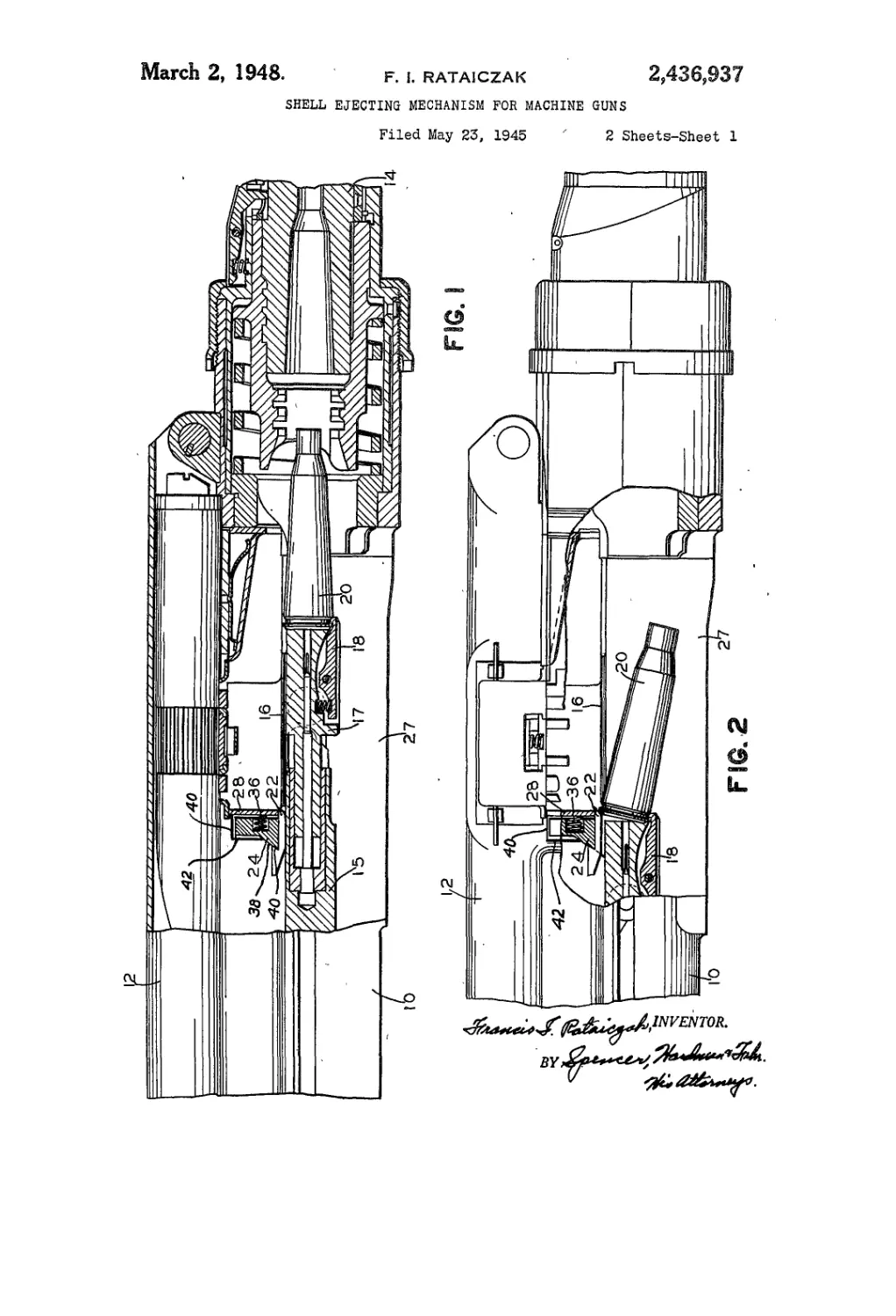
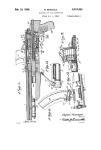
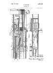
Fig. 1 is a fragmentary view, partly in section,
showing the arrangement of my improved shell
ejecting mechanism relative to the rest of the
gun parts;
Fig. 2 is a fragmentary view, with parts broken
away, showing a shell being ejected by my im-
proved shell ejecting mechanism;
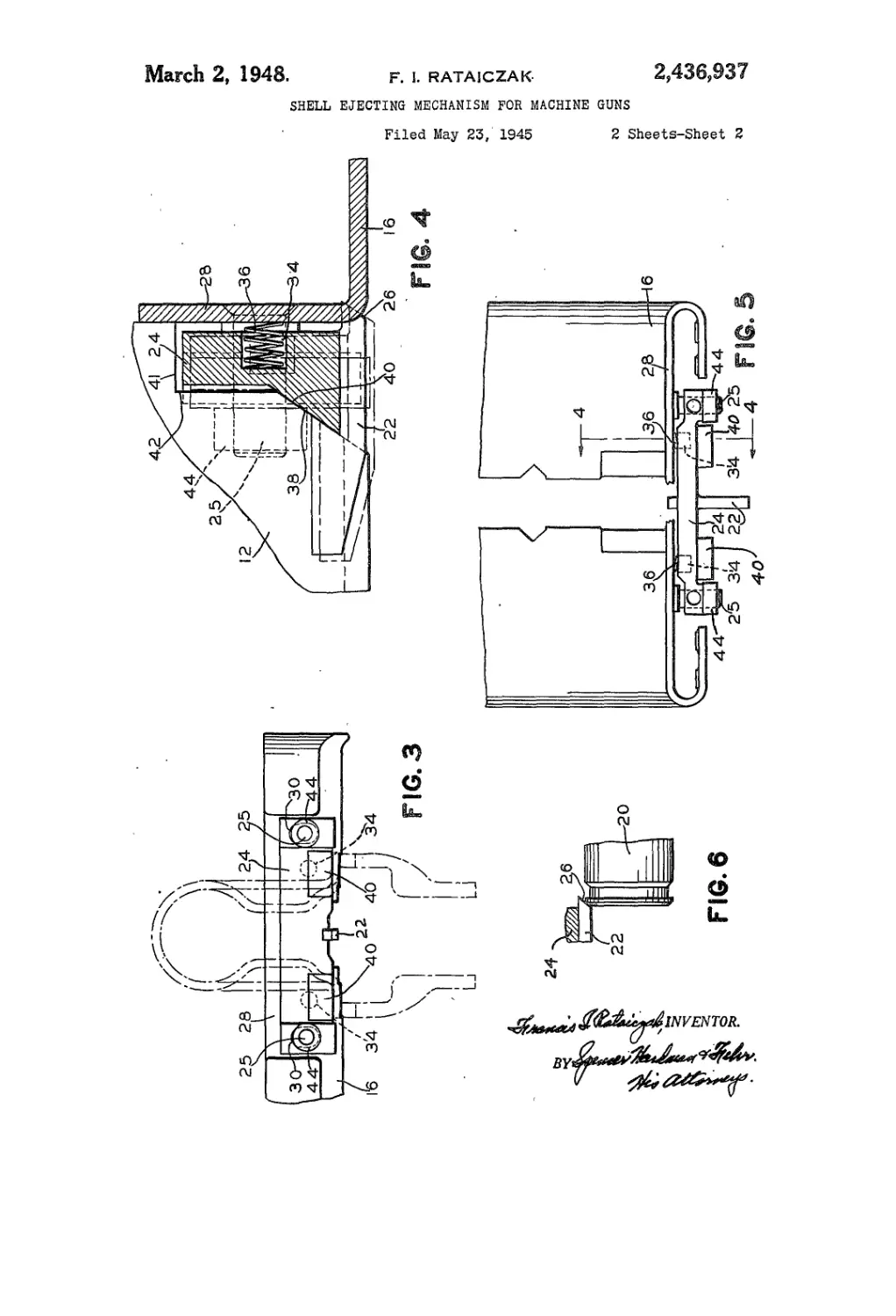
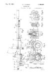
Fig. 3 is a fragmentary elevational view of the
shell ejector and the feedway which has been
superimposed upon a diagrammatic showing of
the receiver and the receiver housing;
Fig. 4 is a fragmentary sectional view taken
substantially on line 4—4 of Fig. 5 showing the
relationship of the shell ejecting mechanism rela-
tive to the feedway and the cover;
Fig. 5 is a top view showing the relationship of
the shell ejecting mechanism to the conventional
feed way; and
Fig. 6 is a fragmentary view on an enlarged
scale showing the relationship of the shell to the
shell ejecting cam when the shell first engages
thecam.
(Cl. 42—25)
2
Referring now to the drawings, reference nu-
merals 10, 12 and 14 designate the receiver hous-
ing, the cover, and the gun barrel, respectively.
As set forth more fully in my со-pending appli-
5 cations, the shells are fed into the gun on a feed-
way 16 which is held in place between the re-
ceiver 10 and the cover 12. The bolt mechanism
comprises a main portion 15 and a bolt head 17
both of which are mounted for reciprocation
10 within the receiver 10 in accordance with pres-
ent practice. The bolt head 17 is provided with
a conventional type of extractor 18 which serves
to extract the empty shells from the barrel 14
as the bolt and bolt head move to the rear upon
15 recoil. As best shown in Fig. 2, the empty shell
20 strikes against a shell ejecting cam 22 which
is carried by and actually formed as an integral
part of the mounting bar 24 as shown in Figs. 3,
4 and 5. The shell ejecting cam 22 is yieldably
20 mounted so as to provide for movement of the
cam relative to the bolt head, the cover and the
rest of the gun elements. The ejected shells
leave through the ejection opening 27 in the bot-
tom of the receiver 10.
25 As best shown in Figs. 3 and 5, the mounting
bar 24 is loosely or adjustably supported by
means of studs 25 rigidly carried by the end wall
28 of the conventional feedway 16. The mount-
ing bar 24 is provided with elongated slots 30
30 through which the studs 25 project so as to guide
and limit the movement of the mounting bar 24.
The relationship of the mounting bar 24, the
shell ejecting cam 22 and the feedway 16 is shown
in Fig. 5 wherein a portion of the end wall 28
35 which is directly above the cam 22, has been
broken away to facilitate illustration. As best
shown in Figs. 4 and 5, holes 34 have been drilled
into the front face of the mounting bar 24 for
the reception of spring means 36 as shown. The
40 springs 36 serve to bias the mounting bar 24
away from the rear wall 28 of the feedway 16.
Referring now to Fig. 4, it will be observed that
the cover 12 is provided with a cam surface 38
which cooperates with a complementary cam
45 surface 40 formed on the mounting bar 24. Each
side flange of the cover 12 is provided with such
a cam surface. The cam surfaces 38 and 40 are
made parallel to the cam surface 26 on the for-
ward end of the ejecting cam 22 and are directly
50 in line with the cam surface 26 so that any force
applied to the cam surface 26 by the empty shell
striking the surface 26 is transmitted directly
to the cover 12 through the surfaces 38.
As shown in Fig. 4, the cover 12 is cut away
55 at 41 and 42 so as to provide clearance between
8,436,037
3
the mounting bar 24 and the edges of the cover
at these places. The pressure of the springs 36
against the bar 24 tends to cause the mounting
bar 24 to move downwardly by virtue of the in-
clined cam surfaces 38 and 40 described herein-
above. The surfaces 38 and 40 are normally in
sliding engagement at all times although there
is relative movement between the bar 24 and the
cover 12. The spring 38 helps to keep the sur-
faces 38 and 40 in contact with one another at
all times. The arrangement of the springs 36
and the surfaces 38 and 40 is such that the bar
24 is biased downwardly by the springs 36. How-
ever, as the bolt head reciprocates within the
receiver housing 10 the cam 22 together with the
mounting bar 24 is free to move upwardly out
of the path of the bolt head. The lower posi-
tion of the ejector has been shown in dot-dash
lines in Fig. 4 of the drawing. By virtue Of this
arrangement, the exact relationship of the cover
relative to the path of the bolt is not as critical
as in the prior shell ejector design shown in my
со-pending application Serial No. 565,252, which
has matured into Patent No. 2,411,979 of Decem-
ber 3, 1946. Furthermore, a slightly different
form of action takes place in that the cover 12
which limits the movement of the mounting bar
24 is at all times in engagement with the mount-
ing bar 24 through the surfaces 38 and 40 in
such a manner that the cover does not receive
a hammer blow from the mounting bar 24 when
the shell strikes the cam surface 26. The studs
25 are provided with removable heads or stops 44
which hold the mounting bar 24 in assembled
relationship relative to the end wall 28. The
arrangement described hereinabove serves as a
convenient self-compensating means capable of
compensating for inaccuracies in the manufac-
ture of the gun and subsequent wear which tends
to alter the clearances between the parts of the
gun.
While the form of embodiment of the inven-
tion as herein disclosed constitutes a preferred
form, it is to be understood that other forms
might be adopted, as may come within the scope
of the claims which follow.
What is claimed is as follows:
1. In a rapid Are machine gun having a re-
ceiver, a receiver cover, shell ejecting mecha-
nism comprising a mounting bar extending
transversely of the receiver between the cover
and the receiver, a shell engaging cam depending
from said bar and arranged so as to engage the
upper rear edge of each empty shell upon extrac-
tion of the shell from the gun barrel, and means
for adjustably mounting said bar, said bar and
said receiver cover having complementary cam
surfaces in sliding engagement with one another
and arranged at an angle relative to the hori-
zontal axis of the gun, said cam surfaces being
so arranged whereby rearward movement of said
bar will cause downward movement of said bar,
and spring means urging said surfaces into en-
gagement with one another.
2. In a rapid Are machine gun having a re-
ceiver housing, a cover for the receiver housing,
and a reciprocating bolt mechanism disposed
within said receiver housing; a shell ejecting
mechanism comprising a shell engaging cam and
mounting means for yieldably supporting said
shell engaging cam between said cover and said
receiver housing, said shell engaging cam com-
prising’ a cam element disposed directly above
and in sliding engagement with said reciprocat-
ing bolt so as to be moved upwardly by said bolt
3
10
15
20
25
30
35
40
45
50
55
60
65
70
75
4
as said bolt moves past said element and having
a forward end for engagement with the chamfer
on the rim of the empty shell, said cover and
said mounting means having complementary
cam surfaces in engagement with one another
and slidable relative to one another, said sur-
faces being arranged so that the shell ejecting
mechanism is cammed forwardly as it moves up-
wardly.
3. In a rapid Are machine gun, a receiver
housing, a cover for said receiver housing, a re-
ciprocating bolt mechanism disposed within said
receiver housing, a shell feedway disposed be-
tween said cover and said receiver housing, a
shell ejecting mechanism carried by said feed-
way and including a depending member having
a cam surface for engaging the upper edge of
the empty shells upon extraction of the shells, a
portion of said depending member being arranged
to project into the path of movement of said
reciprocating bolt mechanism so as to be raised
by said bolt mechanism, said cover and said shell
ejecting mechanism having contacting cam sur-
faces arranged at an angle to the path of move-
ment of said bolt mechanism, and spring means
biasing said contacting cam surfaces into en-
gagement with one another.
4. In a rapid Are machine gun, a receiver
housing, a cover for said receiver housing, a re-
ciprocating bolt mechanism disposed within said
receiver housing, a shell feedway disposed be-
tween said cover and said receiver housing, a
shell ejecting mechanism carried by said feed-
way and including a depending member having
a cam surface for engaging the upper edge of
the empty shells upon extraction of the shells,
a portion of said depending member being ar-
ranged to project into the path of movement of
said reciprocating bolt mechanism so as to be
raised by said bolt mechanism, said cover and
said shell ejecting mechanism having contacting
cam surfaces arranged at an angle to the path
of movement of said bolt mechanism, and spring
means biasing said contacting cam surfaces into
engagement with one another, the arrangement
of said cam sufaces relative to said spring means
being such that said spring means biases the
shell ejecting mechanism downwardly relative to
said cover.
5. In a rapid Are machine gun having a re-
ceiver, a receiver cover, and a feedway mounted
between the receiver and the receiver cover, a
shell ejecting mechanism comprising a mounting
bar loosely carried by said feedway and extend-
ing transversely of the receiver between the cover
and the receiver, a shell engaging element de-
pending from said bar and arranged so as to
engage the upper rear edge of each empty shell
upon extraction of the shell from the gun bar-
rel, spring means interposed between said feed-
way and said mounting bar biasing said mount-
ing bar towards the rear of the gun, said cover
having cam means arranged in engagement with
a portion of said mounting bar for camming said
mounting bar downwardly as the mounting bar
moves to the rear, said cam means, mounting
bar, and feedway being so constructed and ar-
ranged that rearward movement of said mount-
ing bar causes said downward movement.
6. In a rapid Are machine gun, a receiver
housing, a barrel, a cover for said receiver
housing, a reciprocating bolt mechanism disposed
within said receiver housing, said receiver hous-
ing having an ejection opening in the bottom
wall thereof, a shell ejecting mechanism com-
9,436,037
s
prising a shell ejecting cam disposed above the
path of movement of said bolt for engagement
with the empty shells upon extraction from said
barrel and for interrupting backward move-
ment of the upper edge of the shell so as to flip
the shell downwardly through said opening,
means for biasing said shell ejecting mechanism
rearwardly of the gun, and cam means for
camming the shell ejecting mechanism down-
wardly as the shell ejecting mechanism moves
rearwardly.
7. In a firearm, the combination with a re-
ceiver housing; of a shell ejecting mechanism
comprising a mounting bar loosely carried by
said receiver housing, a shell ejecting cam ele-
ment depending from said mounting bar and
having a forward inclined surface for engage-
ment with the rim of an empty shell in the proc-
ess of extraction, means for biasing said mount-
ing bar towards the rear, and cam means for
camming said mounting bar downwardly as the
mounting bar moves towards the rear, said cam
means having a cam surface substantially par-
allel to said inclined surface.
8. In a firearm, the combination with a sta-
tionary receiver housing part; of a shell eject-
ing mechanism comprising a shell ejecting ele-
ment, a mounting bar extending transversely of
said housing for supporting said element in the
path of movement of the edge portion of the
empty shells being extracted from the barrel of
the gun, means for loosely mounting said bar on
said housing part, said last named means being
so constructed and arranged that the mounting
bar is free to move both vertically and horizon-
tally, and means for guiding the movement of
said mounting bar so as to move at an angle
relative to the vertical and the horizontal.
9. In a rapid fire machine gun, a receiver
housing, a barrel, a cover for said receiver hous-
ing, a reciprocating bolt mechanism disposed
within said receiver housing, said receiver hous-
ing having an ejection opening in the bottom
wall thereof, a shell ejecting mechanism com-
prising a shell ejecting cam disposed above the
path of movement of said bolt for engagement
with the empty shells upon extraction from said
barrel and for interrupting backward movement
of the upper edge of the shell so as to flip the
shell downwardly through said opening, a
mounting bar for said shell ejecting cam ar-
6
10
15
20
25
30
35
40
45
50
6
ranged transversely of said receiver housing with
the ends of the bar projecting on opposite sides
of said housing, means for loosely supporting
the projecting ends of said bar, said cover hav-
ing an inclined surface provided thereon, said
mounting bar having a complementary inclined
surface arranged in sliding contact with said first
named inclined surface, and spring means for
biasing said surfaces into mutual engagement,
said spring means and said surfaces being so
constructed and arranged that said shell eject-
ing cam is normally biased downwardly into
shell ejecting position but is allowed to move
upwardly enough so as to allow passage there-
under of said reciprocating bolt mechanism.
10. in a rapid fire machine gun, a receiver
housing, a reciprocating bolt mechanism dis-
posed within said receiver housing, a shell eject-
ing mechanism carried by said housing and in-
cluding a depending member having a cam sur-
face for engaging the upper edge of the empty
shells upon extraction of the shells, a portion
of said depending member being arranged to
project into the path of movement of said re-
ciprocating bolt mechanism so as to be raised by
said bolt mechanism, said housing and said shell
ejecting mechanism having contacting cam sur-
faces arranged at an angle to the path of move-
ment of said bolt mechanism, and spring means
biasing said contacting cam surfaces into en-
gagement with one another, the arrangement of
said cam surfaces relative to said spring means
being such that said spring means bias said
shell ejecting mechanism downwardly relative to
said housing.
FRANCIS I. RATAICZAK.
REFERENCES CITED
The following references are of record in the
file of this patent:
UNITED STATES PATENTS
Number Name Date
580,935 Ehbets________________Apr. 20, 1897
828,977 Schouboe______________Aug. 21, 1906
1,041,410 Benet et al.----------Oct. 15, 1912
1,090,351 Swebilius_____________Mar. 17, 1914
1,786,207 Hudson________________Dec. 23, 1930
2,101,236 Burton__________________Dec. 7, 1937