/


Tags: weapons military affairs machine gun patent
Year: 1930
Text
Dec. 23, 1930.
R F HUDSON
1,786,207
MACHINE GUN
Filed Dec. 12, 1927
5 Sheets-Sheet 1
Dec. 23, 1930
R. F. HUDSON
1,786,207
MACHINE GUN
Filed Dec. 12, 1927 5 Sheets-Sheet 2
Dec. 23, 1930.
R. F. HUDSON
MACHINE GUN
1,786,207
Filed Dec. 12, 1927 5 Sheets-Sheet 3
Dec. 23, 1930
R. F. HUDSON
MACHINE GUN
1,786,207
Dec. 23, 1930
R. F. HUDSON
1,786,207
MACHINE GUN
Filed Dec. 12, 1927
5 Sheets-Sheet 5
QttoT *« tf
Patented Dec. 23, 1930
1,786,207
UNITED STATES PATENT OFFICE
EOBEBT F. HUDSON, OF EICHMOND, VIRGINIA, ASSIGNOB, BY MESNE ASSIGNMENTS,
TO AUTOMATIC GUNS, INC., A COEPOEATION OF DELAW ABE
MACHINE GUN
Application filed December 12, 1927. Serial No. 239,437.
This invention relates to improvements in
machine guns, one object of the invention
being the provision of a machine gun in which
the gases of explosion act to reduce the re-
$ coil, particularly after the initial movement
of the projectile within the barrel, there being
provided novel mechanism by means of which
the forward action of the gases are utilized
to produce this effect, the particular struc-
Ю ture of this application being the outcome of
experimentation and perfecting of the struc-
ture as shown and described in my co-pend-
ing application filed February 28th, 1923,
Serial No. 621,824,
16 Another object of this invention is the
provision of a power-storing device adapted
to be actuated by the gases of explosion, so
that the cartridge is exploded and remains
within the breech of the barrel for a predeter-
80 mined period before the operation of the
power storage device takes place, the power
storage device then operating means for
reciprocating the breech block and during
such reciprocation to eject the spent shell, re-
25 load a new cartridge, and set and release the
firing pin.
Another object of this invention is the pro-
vision of a motor operated synchronized
machine gun that is positively controlled so
30 as to prevent the opening of the breech in
case or a misfire or hangfire.
Another object of this invention is the pro-
vision of a machine gun so designed that in
the event of a hangfire or misfire the gun is
35 automatically halted, the firing can only be
resumed by removing the hangfire shell or
mutilated shell, and the introduction of a
new cartridge, thus providing a gun that
does not permit the placing of a new-cartridge
40 in firing position while the mutilated or
hangfire shell is still in the chamber.
Another object of this invention is the pro-
vision of means whereby should a spent shell
remain in the breech of the barrel or a car-
45 tridge -fail to explode, the gun will cease fir-
ing and cannot be operated again until the
cartridge or damaged shell is removed from
the breech of the barrel.
Another object of this invention is the pro-
se vision in a gun of this type especially adapted
for use in small to large calibers, the range
so far having been undetermined, but with
possibilities from thirty caliber, the shell
used in small arms, up to seventy five (7ft)
millimeters, and the mechanism being so ar- eg
ranged and constructed as to be operated as
a single shot, or any number of repeating
shots, and to be operated manually, auto-
matically or through the instrumentality of
a machine such as the motor of an airplane, eo
the same being so constructed as to be
readily synchronized with the propeller and
operated directly from the shaft of the
engine. _
Another object of the present invention is 55
to so house the movable parts at the breech
of the gun so as to protect them from flying
sand and the like.
With the foregoing and other objects in
view, the invention resides in & novel ar- fa
rangement of machine-gun in which the gases
of -explosion are used merely as a setting
means while spring-actuated means are em-
ployed as the real operating mechanism for
the gun, thus providing in a gun of this type 75
a stationary barrel gun with the least possible
recoil and one in which the rapidity of fire
may be regulated as, for instance, from a
single shot per minute up to one thousand
shots per minute. so
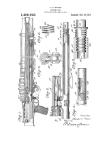
In the accompanying drawings:—
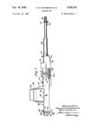
Figure 1 is a side elevation of the com-
plete gun less the mounting or tripod.
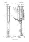
Figure 2 is a longitudinal sectional view
of the rear portion of the gun with the parts 85
in the position they assume with the car-
tridge in the barrel and the firing pin re-
tracted ready to be released.
Figure 3 is a section taken on the line 3—3
of Figure 1 with the firing pin in its rear-
ward position.
Figures 4 and 4a are to be taken as a single
figure and illustrate the gun in longitudinal
section with the parts in the position .they as-
sume at a midway operating position from
the spring, that is, after the gas-actuated •
piston has started to return due to the action
of the spring and showing the breach block
in the position as shown in Figure 3. Ж
Figure 5 is a section taken on the line 5—5
of Figure 1.
Figure 6 is a section taken on the line 6—6
of Figure 1.
6 Figure 7 is a section taken on the line 7—7
of Figure 1.
, Figure 8 is a section taken on the line 8—8
of Figure 1.
Figure 9 is a section taken on the line 9—9
jo of Figure 1.
Figure 10 is a section taken on the line
10—10 of Figure 1.
Figure 11 is a horizontal section through
the breach block showing the firing pin in
jS forward position.
Figure 12 is a top plan view of the breech
block showing the firing pin in slightly re-
tracted position.
Figure 13 is a longitudinal sectional view
20 taken vertically through the breech block
showing the firing pin in the position it as-
sumes just after having struck the fulminat-
ing cap with the cartridge.
Figure 14 is a perspective view of the firing
25 pin locking device.
"Figure 15 is a horizontal sectional view
through the receiver showing the spent car-
tridge throwing means in a retracted posi-
tion.
30 Figure 16 is a similar view showing them
in retracted position engaging the spent shell
to insure the espelling of the same from the
receiver.
Figure 17 is a section taken on the line
35 17—17 of Figure 16.
Figure 18 is an enlarged sectional view
showing the ratchet mechanism for operat-
ing the breech block operating mechanism
and a modified form of gas-actuated plunger,
so Figure 19 is a sectional view showing the
forward end of the spring-carrying barrel
with the modified form of a gas-actuated
plunger.
Figure 20 is a view in elevation of the
45 modified form of gas-actuated plunger and
the movable member of the ratchet carried
and controlled thereby.
Figures 21 and 22 are perspective and plan
views of the locking device and the cartridge
50 guide actuating means.
Figure 23 is a view illustrating the same
and the cartridge guide itself.
Figure 24 is a longitudinal sectional view
through the means for regulating the speed
55 of fire.
Figure 25 is a rear end view thereof show-
ing the mechanism for operating the same at
will.
Figure 26 is a section on the line 26—26 of
so Figure 24.
Referring to the drawings, the numeral 20
designates the receiver portion of the gun to
which is attached, in any desirable manner,
the fixed barrel 21, which, as shown, is pro-
65 vided with the breech 21' for the reception
of the cartridge C. The barrel, as here
shown, threadedly engages the receiver at
22 and is jacketed at the connecting portion
with the receiver with a jacket 23 which forms
a continuation of the rear jacket 24 which
houses the receiver and breech block mecha-
nism, so that the same cannot be interfered
with by dust, sand or other foreign sub-
stances. The side walls 25 of the receiver
have removably connected thereto the lower
section 26 of the casing, which, in turn, is se-
cured in any desirable manner, but in such
a way as to be readily removed so as to render
the parts accessible.
Mounted within the receiver casing is the 80
receiver block 27 which, as shown in Figures
5 and 6, is provided with a bore having the
lateral portions 28, 29 and 30 for the recep-
tion of the breech block 31. This breech
block, the detail construction of which is 85
shown in Figures 11, 12 and 13, will be de-
scribed in detail later on, but is mounted for
reciprocatory movement within the receiver
and is guided in a straight-line movement
from the breech of the barrel to and from oo
the rear of the receiver, the same being pro-
vided with an anti-frictional pin 32 which
rides in the cam groove 33 of the rotary cam
or drum 34, which, in turn, is supported with-
in the receiver anti-frictionally upon a bear- 05
ing В at one end where the shaft 35 extends
rearwardly and is here shown as provided
with a pawl and ratchet 36 and 37 operable
by means of the handle 38, which may be
taken as indicative, of any mechanism by 100
means of which the cam drum 34 may be ro-
tated, as, for instance, the shaft of an air-
plane engine.
The forward shaft 39 of the drum 34 is pro-
vided with a recess 40 and a diametrically 105
disposed pin 41 which receives the bifurcated
end of the shaft 42, which shaft, in turn, is
mounted at its forward end in the ball-bear-
, ing B' and carries the mutilated disk 43 which
is shown in detail in Figures 21, 22 and 23, uo
the same being provided with a groove 43',
the shoulder portion of which is adapted to
form one member of the lock to prevent the
rotation of the drum, as will presently ap-
pear. Upon the forward end of the shaft 42 115
is provided one member 44 of a clutch 45, said
clutch 45 being carried cooperatively by the
members 44 and 48, the member 48, as shown,
being provided with a spiral ratchet groove
49 which, in turn, receives the lug 50 of the 120
operating frame or member 51. This mem-
ber 48 is provided with a pin 47 which fits
within a recessed end of the forward clutch
member 44 while its forward shaft 52 is
mounted for slight sliding and rotary move- J25
ment in the opening 53 of the sleeve 54 which-
is pinned to the barrel by means of a wedge
pin 55, as clearly shown in Figure 4a.
The ratchet operated frame 51 is connected
to a shaft 58 and this shaft is mounted for 130
1,786,207
3
sliding movement within the cylinder 57,
which, in turn, is secured and carried by the
sleeve 54 and receives for reciprocation the
gas-actuated piston 59, the forward end of
g the member 51 being provided with the spring
propelled locking means or pin 53 which is
adapted to project through the opening 54 and
engage the mutilated disk 43 which, at the
proper time, in case of a mis-fire, will engage
IQ the recess 43' and thus lock the drum 34
against rotation. This will also take place
should the last shell be exploded and be with-
drawn from the barrel.
In order that gas may be admitted to the
»5 cylinder 57 at the rear of the piston 59, there
is a small port 60 formed in the barrel and
leading into the bore thereof, while the port
61 of the cylinder 57 is aligned therewith.
Extending forwardly of the cylinder 57 and
2o seated therewithin is the spring-encasing
barrel 62 which is supported at its forward
end in the sleeve or strap 63 pinned, as at 64,
to the barrel and provided with the outer
sleeve 65 at the forward end for encasing the
2@ power-storing device or spring 66, by means
of which, as will presently appear, and by
this means only, the cam drum 34 is rotated,
the ends of the barrel 62 and the sleeve 65 be-
ing closed by the cap 67 provided with the
80 exhaust aperture 68.
From the foregoing description, it is evi-
dent that as the cartridge is exploded, gas
will enter the ports 60 and 61 and thus move
the piston 59 from the position as shown in
35 Figure 2 forwardly to a position slightly be-
yond that shown in Figure 4a, compressing
the spring 66. This takes place during the
time that the cartridge has been exploded and
the bullet has left the muzzle, but the shell
40 or case is still within the breech of the barrel.
The spring 66 after being fully compressed
is then free to through the rotary ratchet
driver to rotate the drum 34 and thus recipro-
cate the breech block 31.
As clearly shown in Figures 11, 12 and 13,
the breech block consists of a member 31 pro-
vided with a bore 69 therethrough which is
slightly reduced at its forward end and open
at 79 for the projection of the fulminating
60 cap-engaging end 80 of the firing pin 7, it
being provided intermediate its ends with
the fixed guide sleeve 72 which receives the
forward end of the spring mounted upon the
firing pin and which itself at the opposite end
65 bears against the sleeve 74 which is provided
with a recess 75 to receive the pivoted lock 76
and thus hold the firing pin removably within
the bore, so that the same may be removed
at will for adjustment, repair and replace-
30 ment. The head 77 is provided to, as will
presently appear, engage the cam projection
81 of the drum 34, a rear edge 32 engaging
the head 72 and retracting it, as shown in
Figure 2, to be released at a slight movement
is of the drum so as to explode the cartridge.
In order to prevent a back-firing from in-
juring the firing pin, the forward end thereof
is grooved, as at 78., so that gases may escape
through the opening 80 and the outlet 71 with-
out injuring the parts.
The cartridge ejector consists of two mem- 70
bers 85 which are loosely mounted for slight
outward and. forward movement upon the
pin and slot arrangement 83 and 84 within
side grooves formed in the breech block, the
same being normally held inwardly by means 7u
of the resilient anti-frictional release 86
against the tension of the small springs 87,
so that the rim-engaging ends 88 may be
properly disposed arid operated from the posi-
tion as shown in Figure 11, where they are 80
in rim-engaging position, to the position as
shown in Figures 12 and 16, where they are
shown in rim-releasing position. These mem-
bers 85 are guided by the walls, and, as be-
fore stated, the anti-frictional members 86 So
of the receiver, and are normally tensioned
outwardly, so that the same are held inward-
ly to grip the shell or be in a position to en-
gage the same, as shown in Figures 11 and oa
15, there, however, being, when the shell is
seated within the breech block, a slight play
between the ends 88 and the rim R of the
cartridge, so that upon the initial recession
or retractive movement of the breech block, e-
a slight tap is given the rim of the cartridge
to release the same before the initial strain
is thrown upon the rim to withdraw the same
from the barrel, this being done due to the
fact that in many cases the explosive action j0(>
fractures the shell, and if a too-sudden grip
is taken with the rearward movement of the
breech block, the rim leaves the shell within
the barrel and thus renders it necessary to
cease firing and remove the same. This also 10B
gives a delayed extraction—to allow pressure
to lower and release casing walls of empty
shell.
In order to provide a means to insure the
ejection of the shell from the receiver, a de- p0
vice, as clearly shown in Figures 15, 16 and
17, is employed. This consists of two small
casings 89 connected upon opposite sides of
the receiver and having mounted therein the
angular-shaped plungers 90 which are spring- цд
propelled and are acted upon by means of
the breech block to retract the same within
the casings upon the forward movement of
the breech block, but are propelled by the
members 91 outwardly so as to assume the 120
position shown in Figures 16 and 17 where
the end 92 thereof engages the spent shell C
above the center line and adjacent the rim
thereof simultaneously with the release of
the rim-engaging portions 88 of the cartridge 126
extractor, thus causing the shell to be released
and thrown down through the lower open
portion of the receiver with the mechanism in
Che position to receive the next cartridge for
delivery to the breech of the barrel. 180
1,786,20?
5
10
S5
20
25
30
35
40
45
50
5S
60
There is also provided a means for lock-
ing the firing pin with the fulminating cap-
engaging end 79 within the breech block, as
shown in Figure 12, this being accomplished
by means of the pivoted locking member 82
whose terminals 83 are pivotally connected to
and bodily carried by the breech block to
cooperate with the upper wall 29 of the re-
ceiver, which acts in opposition to the spring
84 to press the pivoted member 82 down-
wardly and through its peculiar cam action
against the end 77 to move the firing pin
slightly to the rear so that the end 79 is
retracted within the block and, therefore, is
in no danger of prematurely exploding a ful-
minating cap, and renders it possible to make
the firing pin in a single element instead of
in two sections, as is the usual practice.
In order to provide a means whereby the
forward end of the cartridge is properly
guided within the breech of the barrel, and
also to lock the mechanism in case the shell
is not extracted due to the rim being torn off
and the like, the guide 94 having the bullet
receptacle 95 and with the lateral wings 96
is mounted at the rear of the breech of the
barrel within the receiver upon the guide
rods 97, being forced upwardly by springs
mounted on the rods 97. The guide 94 is
moved downwardly by the breech block when
the block is moved forwardly and lowers the
shell guide and lever G, which is pivoted at g
and has its pin 94' engaging the guide 94.
Thus, when the spent shell or hangfire car-
tridge is still in the barrel, the guide is locked
by the same so that the locking lug 98 is in
the path to engage the cooperating locking
lug 99 carried by the shaft 39, and thus bolt
the mechanism. It is now necessary that the
spent or mutilated shell be manually removed,
and inasmuch as the lugs 98 and 99 are timed
to engage about one-eighth of a revolution
ahead of the lug 34' being engaged by the
lock t of the trigger T, it is evident that the
spring 66 when lugs 98 and 99 are released
and the shell extracted or removed will ro-
tate the shaft 39 one-eighth of a revolution
before it is bolted, thus setting the gun for
the next shot as the fired shot is now in a
position to be automatically moved forward
for its seated position, as illustrated in Fig.
4 to the position as shown in Fig. 2.
As shown in Figures 18,19 and 20, the pis-
ton 59' is provided with a guide sleeve 100
slidably mounted upon the ratchet carrying
rod 58' which, at the forward end, is pro-
vided with the fixed stop and buffer end 101,
a spring 102 being mounted upon the rod 58'
and interposed between the member 101 and
the plunger 59'. This is provided to take the
initial impact from the gas entering the cyl-
inder 57' and so as not to throw too great
strain upon the rod 58' and tend to fracture
tile metal at its junction with the ratchet op-
erating member 51'.
Mounted in the forward end of the barrel
62' carrying the springs 66 is a main buffer
rod 103 whose forward end is guided in the
apertured portion 104 and provided with a
head 105, which, in turn, is held rearwardly
by means of the extra heavy spring 106, the
purpose of this being that when the plunger
59 has been thrown forward and carries with
it the rod 58', the buffer end 101 is brought
into contact with the inner end of the main 75
buffer rod 103 and the spring 106 cushions
the final end of this blow and slightly as-
sists in the return of the same in conjunction
with the springs 66'. This is an alternative
construction to that shown and described in 80
the other drawings.
Mounted in the removable end 24' of the
receiver, which, by the way, is so disposed
as to be readily slid vertically into and out
of breech-sealing position, is the casing 108 8$
which is what I term the speed-regulating
device of the present gun, the same being
made of two members, the rear member of
which 109 is provided with a bore, while the
member 108 is also provided with a bore that 90
is concentric therewith. The buffer member
110 projects through the opening 107 of the
receiver and into the receiver in the direct
path of the center line of the breech block or
bolt and below the firing pin, as particularly ' 95
illustrated in Figures 2 and 4, the position in
Figure 2 being that when the member 110
is extended to its full inward limit, while
that shown in Figure 4 shows it retracted to
its full limit. 100
There is mounted for sliding movement
with the member 110 within the cylinder 108
a plunger which consists of the three mem-
bers 111, 112 and 113 connected together so
as to provide the necessary air-tight connec- 105
tion when the plunger is mbved rearwardly
due to the retractive action of the breech
block when the same is moved rearwardly by
means of the drum 34 through the action of
the spring 66 only. A light spring 14 is no
mounted within the buffer member 110 and
surrounds the pin 115 which, in turn, is
mounted for slight rotary movement within
the rear cap 117 of the present device, there
being mounted within the member 109 for 115
slight sliding movement the buffer which
consists of the fiber disk 116 mounted and
carried by the plunger 117 and the cushioning
spring 118. Thus, when the plunger of this
device is moved rearwardly by means of the 120
buffer rod 110 when engaged by the breech
block under spring action, the rear end there-
of will engage the buffer disk 116 and the
spring 118 will take up the final pressure im-
posed thereon and will give a forward im- 125
pulse to the breech block after being com-
pressed and upon movement the return of
the breech block through its spring actuated
means.
The cap 117', as shown, is provided with a 130
1,786,207
5
plurality of openings 117" which, in turn,
are controlled by means of the valve 119
mounted upon the rod 115 and through the
instrumentality of the burred or milled but-
5 ton Ъ may be moved to uncover any number
of said openings according to the graduated
scale shown at the rear of the cap 117', as
shown in Figure 25, the indicating arm or
stop 120 being carried by the button Ъ and
10 limited in its movements from zero to the
last graduation by means of the respective
pins 122 and 123.
By this means it will be seen that the gun-
ner at will can manipulate the button Ъ and
15 thus regulate the escape of air from the rear
of the two plungers within the fire-regulat-
ing device so as to increase the rapidity of fire
or.decrease it, the greater the opening the
more rapid the closing of all the openings
20 cutting down the speed of fire to a minimum.
A trigger T with the spring actuated mem-
ber t is carried at the rear lower portion of
the receiver, as shown in Figure 4, and is
disposed to engage the lug 34' carried by
25 the drum 34 to lock the drum against rota-
tion when the parts assume the position as
shown in Figure 4 with the breech block re-
tracted to its extreme rearward position with
the spent cartridge expelled and with the
30 new cartridge about to be fed. Thus the
spring 66 is still in a position to operate the
arum 34, it being little more than one-half
compressed so that the actuation of the trig-
ger T to release its member t from the lug
35 34 will permit the continued rotation of the
drum 34, the feeding of the cartridge within
the barrel and the explosion thereof, the same
when released locking the drum 34 against
further rotation when the complete cycle
'0 from the position and to the position of Fig-
ure 4 has been performed.
It will be noted in this gun that the plung-
er 59, 59' is always moved forward by gas
action, thus pulling the same against the re-
45 coil inertia, so that the recoil of a gun of
this type is greatly decreased and, in faet,
it has been found in practice that a fifty-
caliber gun of this model can be mounted
upon a sixty-pound tripod, the usual tvpe
50 employed with the present thirty-caliber
rapid fire gun, and that with this thirty-
caliber. mount the initial recoil amounts to
practically nil, thus providing a gun of this
type with practically no recoil or with so
‘ 5 little recoil as not to interfere with the marks-
manship or aiming of the gun.
In order, however, to assist further in
lessening the recoil, to slightly deaden the
noise due to the explosion, and at the same
•® time cover the flame expelled from the muzzle
of the gun, the device, as particularly illus-
trated m Figure 4a, is connected, as at 124,
to the forward end or muzzle of the barrel
and consists of the base member 125 provid-
®' ing a base chamber and having cast integral
therewith the perforated gas-admitting disk
126 and the projectile guiding tube 127. This
guiding tube is provided with the perfora-
tions 128 for the escape of gas and the break-
ing up of the chain of flow of the same, while 7®
also attached to and carried by this sleeve
127 is the metal spiral 129, spaced at its
edge from the casing 131 and extending the
full length thereof, so as to provide a spiral
gas-directing chamber 130 within the casing 75
131 which is connected to and carried by the
support 125, there being attached to the for-
ward end of the casing 131 and also to the
forward end of the tube 127 the perforated
cap 132. Thus the gases of explosion after so
being discharged from the muzzle of the
barrel and entering the chamber of the mem-
ber 125 have two avenues of escape, one di-
rectly through the tube 127 which acts as a
projectile guide and through the openings in 85
the plate 126 into the spiral chamber where
the gases are given a retarded muffled action
before the escape through the forward disk
132 and through the ports 128 into the tube
127, or vice versa. «о
By this means, the construction or ar-
rangement of the spiral reduces the recoil ac-
tion in the gun and has a tendency in prac-
tice to pull the gun forwardly, the tube be-
ing so constructed as to not in any way inter- 95
fere with the marksmanship, either as to
obliterating the sight or the occurrence of
gas, as is the case where the spiral is carried
by the casing 131 and no sleeve as 127 is
provided. 100
The spaces between the outer edges of the
blades of the spiral and the casing 131 pre-
vent the accumulation of dirt or carbon and
also assist in the dissipating and braking gas
action. 105
The usual sights S and S' are provided
upon a gun of this type and are adjustable
at will.
This gun is also .constructed to use either
the vertical cartridge feeding magazine M 110
detachably connected in place by means of
the spring-propelled pin 133 or a belt-feed
may be provided. By means of the pin P
the ratchet-actuating member 51 and its shaft
53 may be manually retracted against the 115
spring at the initial setting of the gun.
The peculiar formation of the cartridge
extractor 85 as before stated permits slight
movement of its rim-engaging fingers 88 to
play in the rim groove to give a slight tap
on the rim at the initial extraction, but this
is not all, as it has been found in practice
that it also permits a delayed extraction of
the shell or case, thus allowing the pressure ig5
of the exploding gases to lower and release
the impinging of the walls of the shell against
the breech of the barrel, making it much easier
to extract and reducing the possibility of a
mutilated shell, as is the case when the shell 130
1,786,207
5
10
IS
20
25
30
35
40
45
®®
55
60
65
is extracted too soon or while under pressure
in the breech.
It will also be noted that the locking mech-
anism consisting of the pin 53 and the disk
43 is brought into play, due to a miss or
hangfire, while the locking device 98—99 is
brought into action due to retention of a
shell or case in the breech, thus providing
two automatic locks that bolt the mechanism
so that it is impossible for a cartridge to be
fed or inserted in the breech of the barrel,
until the evil is corrected by the manual
removal of the cause. This is particularly
desirable when the supersensitive nose fuse
cartridges are being used, for if the gun is
not immediately bolted, the next cartridge
is forced into or against the obstruction and
damage to the gun results.
In the automatic halting of the mechanism
for any one of these causes and by either
locking mechanism, fire can be resumed only
by releasing either the lock 53 or 98. the re-
moval of the obstruction permitting the drum
34 to rotate until halted in either event by
the lug 34' and trigger lock t.
From the foregoing description, taken in
connection with the drawings, it is evident
that with a gun of this type the gases of ex-
plosion are used only to operate the power-
storing device whose plunger, acting for-
wardly, reduces the recoil action of the gun
so as ito make this gun an ideal gun for all
purnoses and for airplane work narticularlv.
while with the addition of the device connect-
ed to the muzzle thereof, the recoil, after the
projectile has been started in flight, is reduced
to a minimum, so that a very accurate non-
recoil firearm of this tvpe is produced.
Bv the peculiar mechanism, the present
construction of machine gun is adapted to
all calibers from the smallest type hand-gun
to fairly large type cannon, while with the
gas driven piston the muzzle brake, regard-
less as to whether the piston compressed
spring is employed to actuate the breech block
for automatic operation, a non-recoil mech-
anism for larger calibre guns and cannons
is herein shown and described, it being prac-
tical to use this mechanism with slight modi-
fication upon 1 inch to 16 inch guns, thus
reducing the cost of mount manufacture, in-
creasing the accuracy and speed of fire, and
increasing the life of the guns.
What I claim as new is:—
1. A machine gun, including a receiver, a
barrel, a breech block reciprocatingly mount-
ed in the receiver, means for actuating the
breech block, power-storing means for oper-
ating the actuating means, means actuated by
the gases of explosion for setting the power-
storing means, and a muzzle brake attached
to the end of barrel and acted upon by the
emitting gases of explosion, whereby the com-
bined action of the gases of explosion act
upon the actuated means and the brake to re-
duce the recoil of the gun.
2. A machine gun, including a barrel, a
receiver, a breech block reciprocatingly
mounted in the receiver, a spring projected
firing pin mounted in the 'breech block,
means for reciprocating the breech block,
and cooperative means carried by the firing
pin and the breech block and operated by the
receiver for slightly retracting the firing pin fs
to encase its cap engaging end during the re-
ciprocation of the breech block.
3. A machine gun according to claim 1,
characterized by the fact that there is exter-
nal means for continuously operating the 8o
breech block actuating means independently
of or in conjunction with the power storing
device.
4. A machine gun, including a barrel hav-
ing a breech, a tube disposed parallel there- gj
with and in communication with the bore of
the barrel at a point approximately the
length of a cartridge beyond the cartridge
chamber of the barrel, a spring returned
plunger mounted in the tube and operated in м
a forward direction by the gases of explo-
sion entering said tube, and a braking device
at the muzzle of the barrel and upon which
the gases of explosion act upon in coopera-
tion with the piston to produce a counter re- gg
coil action to the gun.
5. A machine gun according to claim 4, in
which a buffer for the piston is mounted at
the outer end of the tube.
6. A machine gun according to claim 4, in it
which a spring buffer for the piston is pro-
vided.
7. A machine gun, including a barrel hav-
ing a cartridge chamber and a port leading
from the barrel at a point slightly beyond the щ
inner end of the cartridge chamber, a tube
parallel with the barrel and in communica-
tion therewith through said port, a spring
buffeted piston mounted in said tube to be
moved forwardly by the gases of explosion, ц
and recoil subduing means located at the
muzzle of the barrel for utilizing the velocity
of the gases of explosion after leaving the
muzzle of the barrel.
8. A machine gun according to claim 7, in ц
which an additional buffer for the piston is
provided.
9. A machine gun according to claim 7, in
which an additional spring buffer for the
piston is provided. 12
10. A machine gun, including a receiver,
a barrel connected thereto, a tube parallel
with the barrel and in communication with
the bore of the barrel, a guide rod mounted
in the tube, a sleeve carrying a piston mount- 12
ed upon said rod and slidably mounted in
the tube, a spring acted upon by the piston to
be compressed when the piston is moved in a
forward direction by the gases of explosion,
and a spring buffer in line with to reduce the IS
1,788,207
5
10
15
20
£5
30
35
40
45
50
55
60
65
jar of the guide rod and piston when pro-
pelled by the gases of explosion.
11. A machine gun according to claim 10,
in which a muzzle brake is applied to the end
of the muzzle of the barrel to be acted upon
by the gases of explosion also.
12. A machine gun, including a receiver, a
barrel connected thereto, a breech block
mounted in the receiver, a cartridge extract-
ing mechanism carried by the breech block,
and two oppositely disposed members mount-
ed in the receiver and in the path of the
breech block for engaging a spent shell to
remove the same from the extracting mecha-
nism.
13. A machine gun according to claim 12,
in which said members are spring projected
and are retracted by the breech block during
the time that the receiver is closed or partial-
ly closed by the breech block.
In testimony whereof I have hereunto set
my hand.
ROBERT F. HUDSON.