/

Tags: weapons military affairs machine gun patent
Year: 1936
Text
Feb. 18, 1936.
R. MENDOZA
2,031,383
MACHINE GUN BOLT MECHANISM
Feb. 18, 1936,
2,031,383
R. MENDOZA
MACHINE GUN BOLT MECHANISM
Filed Oct. 1, 1934 3 Sheets-Sheet 2
Feb. 18, 1936.
2,031,383
R. MENDOZA
MACHINE GUN BOLT MECHANISM
Patented Feb. 18, 1936
2,031,383
UNITED STATES PATENT OFFICE
2,031,383
MACHINE GUN BOLT MECHANISM
Rafael Mendoza, Mexico, D. F., Mexico
Application October 1, 1934, Serial No. 746,445
5 Claims. (Cl. 89—3)
5
10
15
20
25
30
35
40
45
50
55
This invention relates to automatic firearms
and more particularly an improved means for
releasably securing the gun barrel to the case or
frame of the gun and which, when in securing’
position, will effectively prevent relative move-
ments between said parts.
With these and other objects in view, this
invention consists in certain novel features of
construction, combination and arrangement of
parts to be hereinafter more fully described and
claimed.
For a complete understanding of my invention,
reference is to be had to the following description
and accompanying drawings, in which
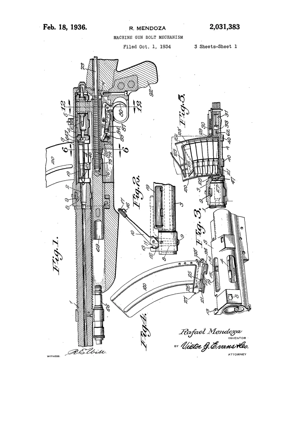
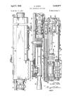
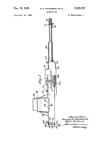
Figure 1 is a fragmentary longitudinal sec-
tional view illustrating an automatic firearm
constructed in accordance with my invention.
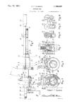
Figure 2 is a fragmentary detail view show-
ing the securing means for effectively and remov-
ably securing the gun barrel to the gun frame or
case.
Figure 3 is a perspective view illustrating a
portion of the gun case or frame.
Figure 4 is a perspective view illustrating the
magazine.
Figure 5 is a fragmentary vertical sectional
view showing the connection between the maga-
zine and the gun case or frame.
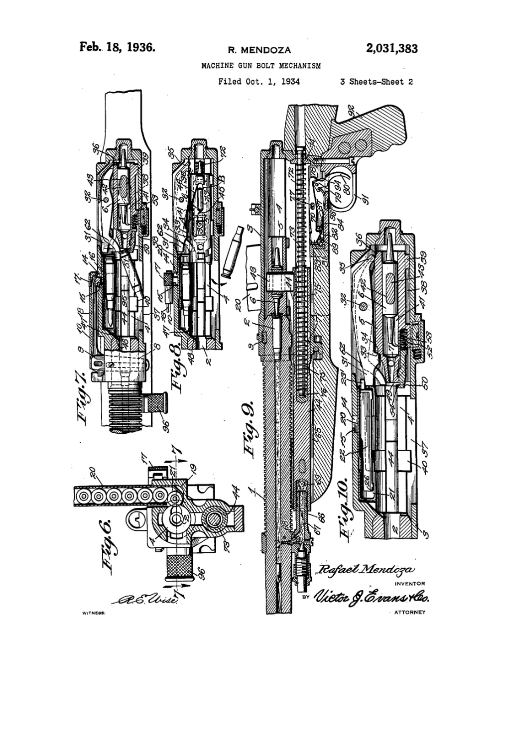
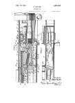
Figure 6 is a transverse sectional view taken
on the line 6—6 of Figure 1.
Figure 7 is a horizontal sectional view showing
the partial ejection of a fired shell from the gun.
Figure 8 is a similar view showing the com-
plete ejection of the fired shell.
Figure 9 is a fragmentary vertical sectional
view showing the firing of a shell and the utiliza-
tion of the explosive charge to return the bolt
and firing pin to cocked or firing position.
Figure 10 is a fragmentary horizontal sectional
view illustrating automatic means for tem-
porarily holding the bolt in firing position on
the exhaustion of ammunition in the magazine
and gun.
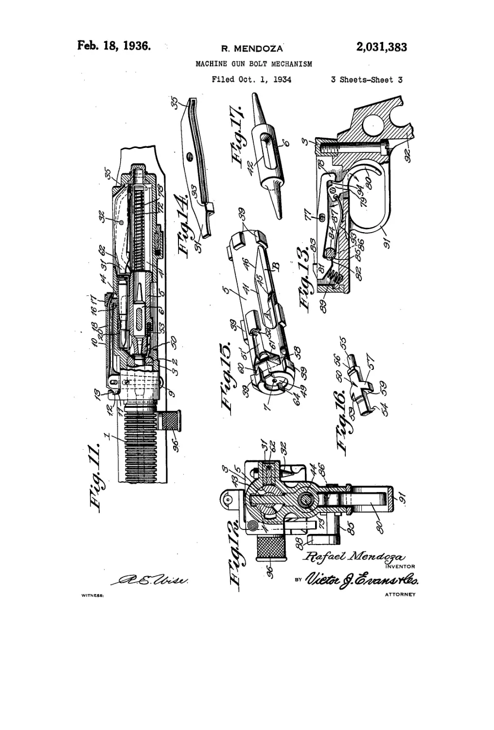
Figure 11 is an enlarged fragmentary hori-
zontal sectional view showing the bolt and firing
pin in firing position and also showing the lock-
ing means between the barrel and the gun frame
or case.
Figure 12 is a transverse sectional view taken
on the line 12—12 of Figure 1.
Figure 13 is a fragmentary view, partly in
section, showing the trigger and sear of the gun
set for semi-automatic firing.
Figure 14 is a perspective view illustrating the
lever for temporarily holding the bolt in cocked
position after the exhaustion of ammunition
from the gun and magazine.
Figure 15 is a perspective view illustrating the
bolt.
Figure 16 is a perspective view illustrating an $
ejector dog carried by the bolt.
Figure 17 is a perspective view illustrating the
firing pin.
Referring in detail to the drawings, the nu-
meral I indicates a gun barrel equipped with а ю
firing chamber 2 in one end thereof and which
end'is removably secured to a gun case or frame 3,
the latter having a chamber .4 to slidably support
a bolt 5 in which is slidably mounted a firing
pin 6, either end of which may be employed for 15
striking the cap of the shell by moving for a
limited distance through an opening 7 provided
in the end of the bolt. The end of the barrel
which is releasably secured to the gun 'frame or
case is provided with a tapered groove 8 to receive 20
a tapered wedge 9 and the latter is pivotally and
slidably connected to a lever 10. A pin and slot
connection is provided between the wedge and
the lever and the pivoted end of said lever has a
cam face i i and a shoulder 12 adapted to abut 25
a shoulder 83 on the gun case or frame when the
lever is in wedge securing position. A slot 14 is
provided in the gun case or frame and presents an
undercut shoulder 15 to be engaged by a catch 16
rigidly secured to a finger piece IT mounted for a 30
limited sliding movement on the lever 10. The
catch 16 when in engagement with the shoulder
15 retains the lever against pivotal movement
and with the shoulder 12 in abutting engagement
with the shoulder 13. A leaf spring 18 is arranged 35
in the lever 10, one end of which bears against
v the outer end of the wedge 9 and the opposite end
is offset to act on the sleeve or finger piece IT for
retaining the catch 10 in engagement with the
shoulder 15. The last-named end of the spring 40
is capable of flexing so that when the finger piece
17 is moved rearwardly with respect to the gun to
disengage the catch 16 from the shoulder 15, said
end of the spring will flex outwardly from the
gun and thereby free thfe lever for pivotal move- 45
ment and as said lever is moved into the posi-
tion, as shown in Figure 2, the cam face III
riding against the gun case or frame will impart
an endwise movement to the wedge to loosen the
latter in the groove of the gun barrel so that said 50
wedge may be easily drawn from the groove of
the gun barrel and the groove provided in the gun,
case or frame whence the barrel may be detached
from the gun case or frame. The parts as
positioned ^ Figure 11, the spring 18 bearing 65
2,031,388
б
10
IB
20
25
30
35
40
45
50
55
60
65
70
75
against the end of the wedge acts to urge said
wedge tightly against the walls of the groove in
the barrel and gun case or frame and thereby
effectively secure the gun barrel and gun case or
frame from having relative movement.
A magazine chamber 19 is formed in one side
of the gun case or frame and at one end opens
outwardly through the top face of the gun case
or frame and the opposite end is communicative
With the chamber 4. A magazine 20 is remov-
ably secured in the magazine chamber 19 with
its outlet end 21 positioned to direct a shell par-
tially into the chamber 4. The magazine is arcu-
ately curved and extends upwardly and forwardly
with respect to the gun, the mouth of the maga-
zine being confined in the magazine chamber and
formed by an arcuately curved flange aiding in
directing the shell partially into the chamber 4.
It is to be understood that the magazine is loaded
With shells from the mouth and operating in the
magazine is a follower 22, operating against the
action of a spring 23 and equipped at one end
with a projection 23' confined within the maga-
zine as long as a shell remains in the magazine
and on the exhaustion of the shells from the mag-
azine the projection is adapted to extend through
a slot 24 in the magazine adjacent the mouth.
A rib 25 is formed on the follower and is dis-
posed at an inclination to engage with a stop or
pin 26 on the magazine as the follower aligns
with the slot 24 to cause an endwise movement
of the follower sufficient to extend the projec-
tion 23' a distance outwardly of the magazine.
A shoulder 27 is provided on the opposite side
of the magazine from the slot 24 and is adapted
to fit under a shoulder 28 formed on a wall of
the magazine chamber 19 adjacent to where said
magazine chamber opens outwardly through the
top face of the gun frame or case. A projection
29 is formed on the opposite side of the magazine
from the projection 27 and when the magazine
is inserted in the magazine chamber the projec-
tion 29 engages with a spring pressed plunger 30
carried by the gun case or frame. The plunger
30 acts to slide the magazine in the chamber end-
wise of the gun to bring the projection 27 under
the shoulder 28, sufficient clearance being pro-
vided in the chamber for permitting a limited
sliding movement of the magazine in the cham-
ber endwise of the gun. To remove the magazine
from the chamber, the latter is slid endwise of
the gun, the plunger 30 yielding to permit the
projection 27 to move from under the shoulder
28 and when in this position the magazine may
be readily withdrawn from the magazine cham-
ber. The purpose of the extension 23' on the
follower 22 is to bring about positioning of a
locking lever 3i to retain the bolt in firing posi-
tion on the exhaustion of shells from the maga-
zine. The lever is pivoted to the gun case or
frame, as shown at 32, and adjacent one end is
provided with a shoulder 33 adapted to be brought
into engagement with a shoulder 34 formed on
the bolt by an opposite end "35 of said lever rid-
ing upon an inclined face 36 located at the other
end of the bolt. The end 35 of the lever is
engaged by the face 36 on the bolt moving into
cocked position consequently bringing the shoul-
der 33 in engagement with the face 34 but as
the lever is pivotally mounted and the shoulder
33 and face 34 so shaped the bolt when driven
or released from cocked position may move into
firing position. However, as the last shell is fed
into the barrel of the gun and the magazine is
exhausted of shells the projection 23' engages
with the lever and prevents pivotal movement
thereof so that the shoulder 33 engaging the face
34 will retain the bolt in cocked position until
such time the magazine is removed from the mag-
azine chamber 19. This arrangement is provided g
so that the bolt will not be released from firing
position by the operator when the shells are ex-
hausted from the magazine and gun keeping the
bolt in cocked position ready to actuate on the
introduction of another magazine filled with jo
shells.
The gun case or frame is equipped with a shell
discharge slot 37 in one side thereof and this
slot communicates With the chamber 4 substan-
tially opposite to the communication of the mag- js
azine chamber with said chamber 4. The walls
of the chamber 4 are provided with longitudi-
nally extending grooves 38 in which operate lugs
39 on the bolt 5 and which permit the bolt 5
to have free sliding movement in the chamber 20
either from cocked to firing position or from the
latter-named position to cocked position. Ar-
ranged at right angles to the grooves 38 are
grooves 40 and are in communication with the
grooves 38 to permit a limited rotation of the 25
bolt as the latter reaches firing position, the
lugs entering said grooves 40. Oppositely ar-
ranged slots 4 i are provided in the bolt and the
firing pin 6 has a slot 42 aligning with said slots
41. Extending through one of the slots 4i and go
through the slot 42 into the other slot 41 is a
projection or arm 43 secured to a plunger 44
forming a part of-a combined firing and cocking
mechanism which will be hereinafter more fully
described. Opposite walls of each slot 41 are 35
cut away to form cam faces 45 and 46 and which
provide to each slot portions A and В one dis-
posed slightly laterally of the other. The bolt
when in cocked position with the lugs 39 lying
in the longitudinal grooves 38, the arm 43 bears 40
against the cam faces 45 so that when the gun is
fired and the arm 43 moves in the direction of the
barrel or firing chamber thereof it drives both the
bolt and firing pin in the direction of the barrel
until the bolt abuts the end of the barrel with 45
the lugs 39 aligning with the grooves 40. The
arm bearing against the cam faces 45 during
this movement of the bolt besides driving the
bolt into firing position it has a tendency to
turn or rotate the bolt and as the lugs align 50
with the grooves 40 the bolt rotates a limited
distance with the arm 43 and firing pin con-
tinuing a sliding movement in the direction of
the barrel or firing chamber thereof so that the
pointed end of the firing pin will pass through 55
the aperture 7 and strike the cap of the shell
with sufficient force to bring about the explosion
of the cap for the purpose of igniting the powder
of the shell. On the sliding movement of the
arm 43 in a reverse direction or in a direction co
to cock the bolt and firing pin, said arm and
firing pin first slide relative to the bolt until the
cam faces 46 are engaged by the arm and the lat-
ter bearing with force against said cam faces
rotates the bolt 5 in a reverse direction to bring c5
the lugs 39 again into the longitudinal grooves
38 whence said bolt may return to a cocked
position along with the firing pin by the influence
of said arm 43.
As heretofore stated, the lowermost shell of 70
the magazine partially extends into the chamber
4 so that the bolt on leaving a cocked position
will engage with the shell and impart endwise
movement thereto and during the initial endwise
movement of the shell the bullet or projectile of 7
2,031,388
the shell engages with inclined faces 47 andz48
formed on the walls of the chamber and the end
of the gun barrel which has the firing so that
said shell will be guided into the firing chamber
5 in advance of the bolt 5. The end of the bolt
which engages with the shell is recessed or cham-
bered to form a seat 49 for the cap end of the
shell to engage in as said shell reaches home in
the firing chamber and which seat permits said
10 end of the bolt to contact firmly and evenly with
the end of the barrel of the gun. As before
stated, the bolt 5 reaches firing position in ad-
vance of the firing pin so that the shell will be
properly positioned in the firing chamber before
16 the firing pin passes through the opening 7 and
strikes the cap of the shell. As the cap end of
the shell moves into the seat 49 a yieldable ejec-
tor dog 50 carried "by the bolt snaps into the
usual annular groove 5i of the cap. The dog
20 50 operates in a groove 5 i' formed in the bolt 5,
one end of this groove extending into the seat
49 while the other end of the groove communi-
cates with a chamber 52 formed on the bolt in
which is positioned a coil spring 53. The dog in-
25 eludes a body of elongated formation having
one end shaped to form a tongue 54 to engage
the groove of the cap of the shell while the op-
posite end is reduced to form a plunger 55 slid-
ably received in the chamber 52 and also pre-
30 sents a shoulder 56 for the spring 53 to bear
against. Lugs 57 are formed on the body of the
dog and are received in a groove 58 formed in
the bolt 5 and intersecting and arranged at right-
angles to the groove 51'. The lugs 57 are pro-
35 vided with beveled faces 59 to contact with un-
dercut faces 68 formed in walls of the grooves
58, the spring 53 acting to keep the faces 59
in engagement with the faces 68. The opposite
wall of the groove 58 from the faces 60 is bev-
40 eled, as shown at 61, which will permit the dog to
have a limited sliding movement endwise of the
bolt 5 against the action of the spring 53 and
also permit the dog to move slightly out of the
groove 51 for the purpose of permitting the end
45 54 to ride over the cap of the shell and enter
the groove of said cap. The dog engaging the
shell as described will extract the shell from the
firing chamber as the bolt moves towards cocked
position, it being understood that the extraction
50 of the shell takes place after the firing there-
of. After the bolt has completed a portion of its
movement towards a cocked position an ejector
lever 62 engages with the cap end of the "shell
and with the continued movement of the bolt to-
55 wards a cocked position the shell is caused to
swing and release itself from the dog and seat
and disengage from the gun by way of the dis-
charge slot 37 provided therefor, as clearly shown
In Figures 7 and 8 of the drawings. The ejec-
60 tor lever is supported intermediate its ends by
the pivot which supports the lever 31. One end
of the ejector lever engages with the outer face
of the bolt during the latter’s movement towards
cocked position causing the opposite end of the
65 lever to move through a slot 64 in the bolt to en-
gage with the cap end of the shell. The slot 64
communicates with the seat 49.
The plunger 44 of the combined firing and cock-
ing mechanism slides in a chamber 65 provided
70 in the gun case or frame. One end of this
chamber is open to the atmosphere and has ex-
tending therein for a short distance a nipple
66, the passage 87 of which communicates with
a passage 68 leading to the barrel of the gun in
75 advance of the firing chamber so that a portion
3
of the firing charge may enter the nipple and
exhaust into a cylinder 69 formed in one end of
the plunger. The explosive force Impinging
against the inner end of the cylinder drives
the plunger rearwardly with respect to the gun 5
and as the arm 43 is carried by the plunger it
will move the bolt and firing pin into cocked po-
sition and as the bolt and firing pin reach the
cocked position a sear 70 engages in a notch 71 of
the plunger. The plunger moving in the direction 10
described compresses a firing spring 72 of the
coil type. The spring 72 is mounted on a rod
73 between a wall 74 of the gun case or frame
and the plunger. The plunger is chambered, as
shown at 75, to permit a portion of the rod 73 15
and the spring to lie within the plunger, the
rod at Its Inner end carrying a head 76 which
abuts with the inner end of the chamber 75 be-
ing held in engagement therewith by the influ-
ence of the firing spring 72. The rod extends 20
through the wall 74 of the gun case or frame so
as to be slidably supported thereby and in turn
aid in slidably supporting the plunger. It is to
be understood that when the plunger is freed by
the sear 70 it is driven forwardly of the gun 25
carrying therewith the bolt 5 and firing pin by
the firing spring 72.
The sear 70 is pivotally and slidably mounted,
as shown at 77, and one end of the sear has a
tongue or projection 78 to engage with a head 80
79 of a trigger 80. The opposite end of the sear
has a head 81 shaped to provide oppositely ar-
ranged shoulders 82 and 83. The shoulder 83
engages in the notch of the plunger while the
shoulder 82 rides upon a cam 84 carried by a 35
shaft 85 journaled to the gun case or frame and
which is provided with angularly related faces
86 engaged by one end of a leaf spring 87. The
cam shaft extends outwardly of the gun case
or frame and is equipped with a finger piece 88 40
whereby the cam 84 may be moved into different
positions and retained in said positions against
accidental movement by the end of the spring 87
bearing against the angularly related faces 86.
A coil spring 89 bears against the head 81 of the 45
sear and acts to position the shoulder 83 to en-
gage in the notch of the plunger 44. A trigger
guard 9 i is secured to the gun case or frame and
includes a hand grip 92 and is provided with a
seat 93 for the spring 87, the latter having one 50
end pivotally connected to the head 79 of the
trigger 80. The trigger extends into the guard
9i in the usual maimer and the head 79 thereof
is provided with a shoulder 94. The spring 89
besides acting to position the shoulder 83 of the 55
sear into the notch of the plunger 44 also im-
parts an endwise movement to the sear in a di-
rection rearwardly with respect to the gun. The
Cam 84 when in one position will retain the
shoulder 83 in the notch of the plunger and pre- 60
vent pivotal movement of the sear by the trigger
thereby providing a safety device to prevent the
gun from accidentally firing. A second position
of the gun, as shown in Figure 9, will position or
slide the sear forwardly a limited distance so that 65
the shoulder 78 will be disposed over the shoulder
04 of the trigger whereby upon moving the trigger
into firing position the sear will he disengaged
from the plunger and permit the firing of the
gun to be automatic and which operation will 70
continue as long as shells are received in the
firing chamber. A third position of the cam, as
shown in Figure 13, will permit the spring 89 to
shift the sear endwise rearwardly of the gun so
that the trigger must be pulled rearwardly and 75
2,081,388
б
10
15
20
25
30
35
40
45
50
55
released on the firing of each shell in the gun,
thereby providing a semi-automatic firing fea-
ture to said gun.
By referring to Figure 13, it will be noted that
the shoulder 94 rides past the shoulder 18 of
the sear when the trigger reaches a full firing
position consequently requiring the release and
return of the trigger to a non-firing position be-
fore the shoulder 94 of the trigger will underlie
the shoulder 18 of the sear.
A cutaway portion 95 is provided in the plunger
and is adapted to align with the chamber 4 when
said plunger moves into position for cocking the
bolt and firing pin so that any particles of for-
eign matter which may accumulate within the
chamber may escape therefrom by said cutaway
portion 95 to obviate any possibility of foreign
matter accumulating to an extent that it would
interfere with the operation of the various parts
operating in said chamber 0. These foreign par-
ticles may come from dirt on the shells or chip-
pings from the shell casing^
Should for any reason the automatic recock-
ing of the gun fail, a hand piece 96 is connected
to the plunger and operates through a slot in
the gun case or frame whereby the plunger may
be moved rearwardly with respect to the gun to
position the bolt and firing pin in cocked po-
sition.
Having described the invention, I claim:
1. A firearm including a gun frame and a bar-
rel removably mounted thereto, said barrel and
frame having tapering grooves to align’when
the barrel is mounted to the frame, a wedge to
enter said groove, a shoulder on the frame, a
lever pivotally and slidably secured to the wedge,
a shoulder on the pivoted end of the lever to
engage the first-named shoulder when said lever
occupies one of its positions, and a cam face on
the pivoted end of said lever to engage the frame
by said lever moving from the stated position to
a second position to urge the wedge out of the
grooves.
2. A firearm including a gun frame and a bar-
rel removably mounted thereto, said barrel , and
frame having tapering grooves to align when'the
barrel is mounted to the frame, a wedge to enter
said grooves, a shoulder on the frame, a lever
pivotally and slidably secured to the wedge,
a shoulder on the pivoted end of the lever, to en-
gage the first-named shoulder when said lever
occupies one of its positions, a cam face on the
pivoted end of said lever to engage the frame by
said lever moving from the stated position to a
second position to urge the wedge out of the
grooves, and a releasable securing means between
said lever and the frame to hold the lever in the
first-named position.
3. A firearm including a gun frame and a bar-
rel removably mounted thereto, said barrel and
frame having tapering grooves to align when
the barrel is mounted to the frame, a wedge to
enter said grooves, a shoulder on the frame, a
lever pivotally and slidably secured to the wedge, 5
a shoulder on the pivoted end of the lever to
engage the first-named shoulder when said lever
occupies one of its positions, a cam face on the
pivoted end of said lever to engage the frame by
said lever moving from the stated position to a 10
second position to urge the wedge out of the
grooves, a keeper on the frame, and a latch mov-
ably mounted on the lever to engage with the
keeper for holding said lever in the first-named
position. 15
4. A firearm including a gun frame and a bar-
rel removably mounted thereto, said barrel and
frame having tapering grooves to align when the
barrel is mounted to the frame, a wedge to enter
said grooves, a shoulder on the frame, a lever 20
pivotally and slidably secured to the wedge, a
shoulder on the pivoted end of the lever to engage
the first-named shoulder when said lever occu-
pies one of its positions, a cam face on the pivoted
end of said lever to engage the frame by said 25
lever moving from the stated position to a second
position to urge the wedge out of the grooves,
a keeper on the frame, a latch movably mount-
ed on the lever to engage with the keeper for
holdling said lever in the first-named position, 30
a' leaf spring carried by the lever and having one
end bearing against the wedge to act to urge
the wedge into the grooves during the time the
lever is occupying the first-named position.
5. A firearm including a gun frame and a bar- 35
rel removably mounted thereto, said barrel and
frame having tapering grooves to align when
the barrel is mounted to the frame, a wedge to
enter said grooves, a shoulder on the frame, a
lever pivotally and slidably secured to the wedge, <0
a shoulder on the pivoted end of the lever to
engage the first-named shoulder when said lever
occupies one of its positions, a cam face on the
pivoted end of said lever to engage the frame
by said lever moving from the stated position 45
to a second position to urge the wedge out of the
grooves, a keeper on the frame, a latch movably
mounted on the lever to engage with the keeper
for holding said lever in the first-named position,
a leaf spring carried by the lever and having one 50
end bearing against the wedge to act to urge
the wedge into the grooves during the time the
lever is occupying the first-named position, said
spring having one end offset to engage the latch
acting to retain said latch in engagement with the 55
keeper and capable of flexing to permit manual
disengagement of the latch from the keeper.
RAFAEL MENDOZA.