/
Tags: weapons military affairs machine gun patent
Year: 1918
Text
C. A. NELSON.
MACHINE GUN.
APPLICATION FILED AUG. 16, 1916.
1,256,923, Patented Feb. 19,1918.
ED STA S PA OFFICE.
CHARLES A. NELSON, OE UTICA, NEW YORK, ASSIGNOR TO SAVAGE ARMS CORPORATION,
A CORPORATION OE DELAWARE.
MACHINE-GUN.
1,256,923. Specification of letters Patent. Patented Feb. 19,1918.
Application filed. August 16,1916. Serial No. 115,127.
To all whom it may concern:
Be it known that I, Charles A. Nelson,
a citizen of the United States, and a resident
of Utica, Oneida county, State of New York,
6 have invented certain new and useful Im-
provements in Machine-Guns, of which the
following is a full, true, and complete speci-
fication.
This invention is an improvement in gas
10 operated machine or similar automatic guns
and relates more particularly to the agents
whereby the gas pressure of the explosion is
utilized for the operation of the loading
mechanism. Merely as an example of a gun
15 having such agents I refer to the well-known
Savage-Lewis machine gun in which there
is employed a gas-impelled rod or plunger
mechanism formed of two sections con-
nected together in alinement, one constitut-
20 ing a piston rod and piston subject to
the gas pressure escaping laterally from
the barrel, and the other section being a mo-
tion - transmitting and motion - distributing
member serving to actuate the several parts
25 of the loading and other mechanism. As
said member moves under the pressure of
the gas imparted to it through the piston
rod, it acts through a cam-slot, or other-
wise, to rotate the breech bolt and unlock it
30 and to carry it rearwardly against spring
pressure until the empty shell is ejected, and
immediately following ejection, the spring
pressure returns the said member, and dur-
ing the return movement a new cartridge is
35 placed in the chamber of the barrel, the
breech bolt being automatically restored and
locked in its {restored position and the firing
pin being cocked or cocked and immediately
released, according to whether the trigger
40 is held pulled during the gas operation.
Other parts are likewise actuated by and
during the reciprocation of the said section.
But, although I have made my invention
primarily as an improvement on the said
45 Savage-Lewis gun, it is also applicable for
use in connection with any other type of gun
or apparatus where. the same, or similar
parts, or a similar cycle is performed, and
the features characterizing my invention
50 are, therefore, broadly claimed below.
The immediate object of the invention is
to avoid or prevent fracture of the recipro-
cating plunger mechanism in the vicinity of
the joint or junction between the piston rod
55 proper and the part or section actuated by
it. These parts for certain reasons are re-
quired to be disconnectible, and in the gun
referred to, as well as in others operating on
the same principle, a condition of stress lo-
calizes at the region of the attachment and 60
fracture of the piston rod, due to crystalli-
zation of the metal, has heretofore fre-
quently resulted attended, of course, with
disablement of the gun. Reinforcement of
the joint in the region of fracture, as by the 65
use of thicker cross-sections, is not a remedy
and is moreover forbidden in any substan-
tial degree by the condition that these guns
must be as light as possible so as to be capa-
ble of use as a shoulder arm. 7(
I have discovered that I can eliminate the
cause of breakage, without thicker metal,
by connecting the two sections with a loose
joint and-a spring for controlling the joint,
by which means I retain the sections in 7
proper relative positions, prevent any mate-
rial endwise movement and prevent localiza-
tion of the injurious stresses in either of the
sections and especially at the place where
fracture is most likely to occur. In its im- s
proved and preferred construction as herein
shown, the loose joint permits a certain rela-
tive rotary movement between sections while
the spring controlling member, preferably a
helical spring, tends to prevent and restrain f
such movement, and the arrangement is,such
that disconnection of the sections can be ac-
complished very readily and without the use
of tools.
In the accompanying drawings I have (
illustrated one form of my invention incor-
porated in the Savage-Lewis machine gun
above alluded to.
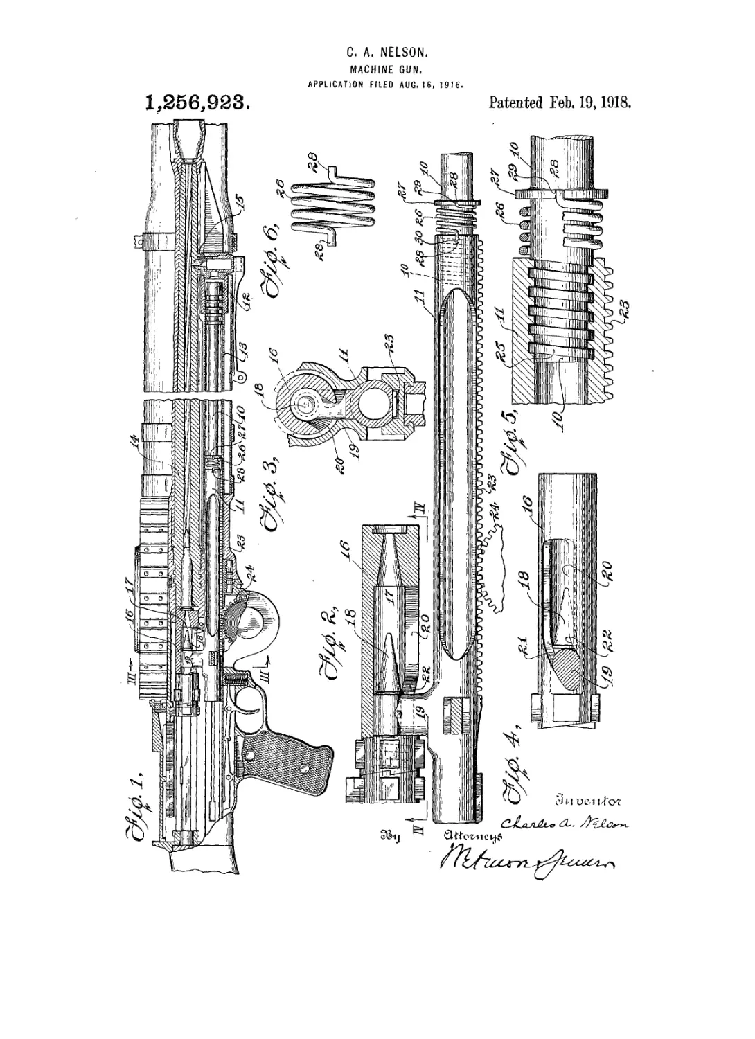
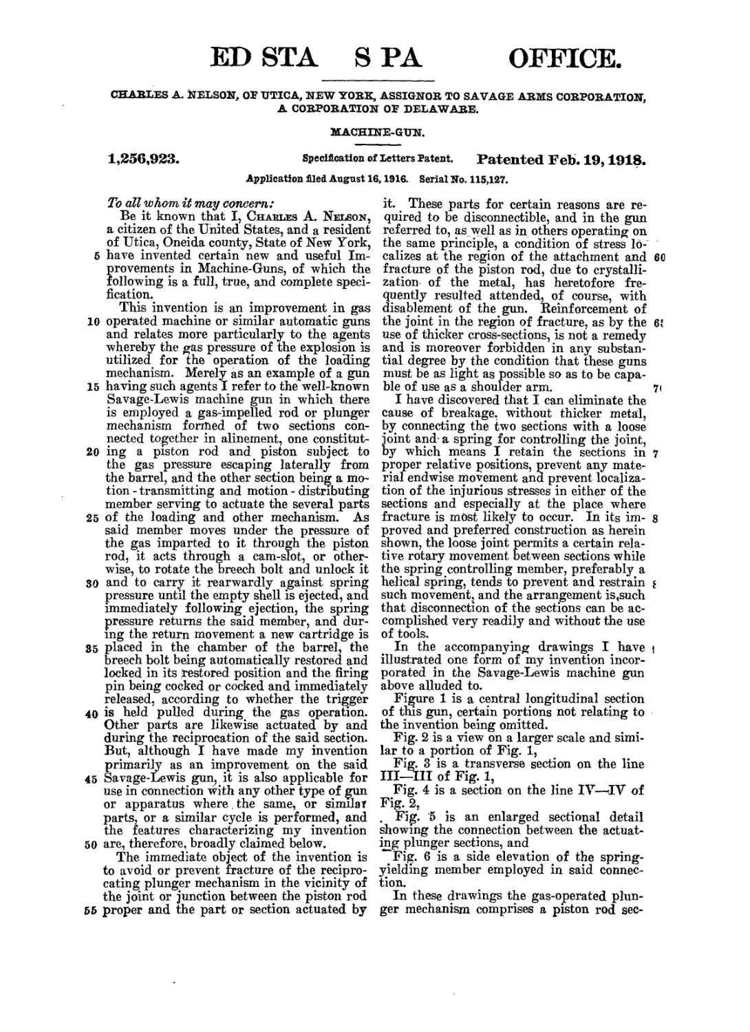
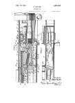
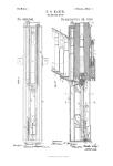
Figure 1 is a central longitudinal section
of this gun, certain portions not relating to
the invention being omitted.
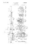
Fig. 2 is a view on a larger scale and simi-
lar to a portion of Fig. 1,
Fig. 3 is a transverse section on the line
III—III of Fig. 1,
Fig. 4 is a section on the line IV—IV of
Fig. 2,
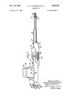
. Fig. 5 is an enlarged sectional detail
showing the connection between the actuat-
ing plunger sections, and
Fig. 6 is a side elevation of the spring-
yielding member employed in said connec-
tion.
In these drawings the gas-operated plun-
ger mechanism comprises a piston rod sec-
1,266,023
Я
tion 10 and a motion-transmitting section 11.
The piston rod section 10 has a piston head
12 at its end and is mounted to slide in a
cylinder 13 secured to the gun barrel 14 and
5 in communication therewith through a vent
15 forward of the piston head. The motion-
transmitting section 11 is connected to the
piston section by the loose joint and spring
presently described, and is mounted to slide
0 partly within the cylinder 13 and partly in
a slideway formed in the receiver of the gun
on which the barrel and many of the other
parts of the gun are mounted. The breech
bolt 16, mounted to slide and also to ro-
> tate in the receiver, and provided with the
usual bayonet lugs for locking with the
breech, is the principal member directly op-
erated by the section 11. In its central
chamber 17 it contains the striker or firing
> pin 18, and the latter is connected to the
post 19 on the section 11, through a slot 20
. ш the wall of the bolt. This slot is curved
or provided with cam surfaces 21 and 22 so
that when the post approaches one end of
the slot, it rotates the breech bolt in one
direction and as it leaves this end of the
slot reverses the rotation and thereby per-
forms the function of locking and unlocking
the bolt as will be understood. The sectional
contour of the section 11 is designed to hold
it to a non-rotary movement of reciproca-
tion in the receiver whereby it may properly
rotate the breech bolt as just described. On
its lower side it is formed with a row of
rack teeth 23 accommodated in a groove in
the receiver and engaged with a spring-
barrel gear-wheel 24. The spring acting
on this gear tends to rotate it in the direc-
tion to restore the section 11 and the piston
rod to their forward position. Each gas-
impelled rearward motion of the piston takes
place against the spring, and the adjusted
tension of the latter controls the rapidity
of fire which in practice is very rapid. The
drawings show the sear and trigger combi-
nation and certain other parts which will
oe recognized without further description.
These have no direct relation to my inven-
ion, which, as above stated, is concerned
vith the integrity of the junction between
he piston rod and the rack member from
vhich the breech bolt, firing pin and other
>arts receive their motion.
The joint between the piston and the rack
aember has heretofore been made by cross-
inning the former in a socket end in the
itter and also by other forms of positive
nd more or less rigid 'connections intended
i provide maximum security, though in
ractice ineffectual for that purpose. If the
lint itself withstands the strain of rapid
ring, the fracture tends to occur in the pis-
>n rod just_ in advance of the joint, and
ue in my opinion to the lack of accommoda-
on in the latter.
In the new joint the socket in the end of
the rack-member is retained and the piston
rod is screw-threaded into it, preferably
with square threads and rather loose, as in-
tended to be shown at 25 in Fig. 5. The 70
governing spring 26, separately shown in
Fig. 6, is placed on the rod between a collar
or shoulder 27 thereon and the end of the
socket, with its out-turned ends 28 seated
in notches 29 and 30, respectively in the 75
socket end and collar. This assemblage may
be accomplished by holding one end of the
spring out of its notch while the rod is being
screwed into the socket and allowing it to
seat in its notch when the rod is in place, so
In the normal relation it is intended that
the spring be free from distortion so that it
will tend to resist relative rotation of the
parts in either direction, and so that it
will restore them to normal if momentarily 85
displaced. Preferably, the pitch of the
threads is so related to the pitch of the coils
of the spring that rotation of the piston
rod in a direction to screw it out of the
socket will contract the spring against the 90
rod and further rotation will be thereby pre-
vented, while rotation in the opposite direc-
tion, will tend to squeeze the coils of the
spring between the collar 27 and the end of
the socket, which eventually forms a posi- 95
tive limit to such reverse rotation. Thus,
the spring itself may constitute a stop for
limiting the relative rotation of the parts in
either direction from normal, but other
means may be provided for preventing ac- 100
cidental separation, where springs -of dif-
ferent form or in different relation are used
for governing the positions of the jointed
parts. The helical form of spring is pre-
ferred for the gun in questiton because of its 105
simplicity and ease of assemblage with the
screw-type of connection, and the said type
of connection is preferred because it is readily
disconnectible while providing maximum
surface to withstand the thrust. Disconnec- no
tion is accomplished by lifting one end of
the spring and unscrewing the rod, no tools
being required. It will be apparent how-
ever, that the sections can be connected in
proper thrust-sustaining relation by other 115
means if desired, so long as their relative
positions are subject to the control of the
spring. My invention is thus not confined
to the specific joint illustrated, although the
features thereof constitute important ad- 120
juncts to the principle thereof.
I claim—
1. A gun having gas-operated plunger
mechanism including a piston section, a mo-
tion-transmitting section, connections for 125
preventing relative longitudinal movement
of the sections, and a spring permitting but
resisting relative rotary movement.
2. Plunger mechanism for automatic, gas-
operated guns including a mechanism actu- 130
1,266,923
ating section, a reciprocating piston section,
a detachable connection for longitudinally
operating one by the other, and resilient
means interposed between the said sections
5 adapted to resist relative rotary movement
therebetween.
3. Plunger mechanism for automatic dis-
charge-actuated guns, including a piston rod
section, a mechanism-actuating section, a
10 connection therebetween whereby the one
may impart longitudinal movement to the
other, and spring means tending to prevent
relative rotary movement between said sec-
tions.
15 4. In apparatus of the kind described the
combination of two reciprocating power-
transmitting sections, subject to rapid end-
wise vibration and connected to each other by
screw-type engaging means and spring
20 means, yieldingly resisting relative rotary
movement between said sections in either
direction.
5. In apparatus of the kind described, the
combination of two reciprocating power-
25 transmitting sections subject to rapid end-
wise vibration and connected to each other
by means permitting relative rotary move-
ment therebetween, and spring-means resist-
ing such movement and providing a posi-
30 tive limit thereto.
6. In apparatus of the kind described, a
rod section, a mechanism actuating section,
a screw-threaded connection between said
sections, and a coil spring restraining rela-
ys tive rotary movement of said sections.
7. In guns of the kind described, a piston
section, a mechanism actuating section, a
8
screw-threaded connection between said sec-
tions, and a coil spring tending to prevent
relative rotary movement of said sections 40
and positively limiting the extent of such
rotary movement in either direction.
8. An actuating rod including two sec-
tions having loose threaded connection with
each other, and a coil spring encircling one 45
section, slightly larger than the portion en-
circled and having one end connected to
each section.
9. An actuating means for automatic ma-
chine guns, including a piston section, a bolt 50
actuating section, and means for preventing
the transmission of excessive stress to the
piston rod section comprising a loose thread-
ed connection between said sections and a
coil spring loosely encircling one section and 55
having one end connected to each section.
10. A reciprocating plunger mechanism
including two sections, one of said sections
having one end threaded into one end of
the other, and a coil spring encircling one to
of said sections adjacent to the other sec-
tion and of slightly larger diameter than
the portion encircled and having its oppo-
site ends connected to the two sections, the
pitch of the screw threads and of the spring 65
coils being such that a relative rotation of
said sections in one direction is limited by
the contraction of the spring against the
part encircled, and relative rotation in the
opposite direction is limited by the endwise 71
compresson of the coils of the spring.
In testimony whereof, I have signed this
specification.
CHARLES A. NELSON.