/
Tags: weapons military affairs
Year: 1958
Similar


Text
DEPARTMENT OF THE ARMY TECHNICAL MANUAL
OPERATION AND ORGANIZATIONAL
MAINTENANCE
CALIBER .22 RIFLE M13
REMINGTON RIFLE M513T
STEVENS RIFLE M416-2T
AND
WINCHESTER RIFLE M75T
HEADQUARTERS, DEPARTMENT OF THE ARMY
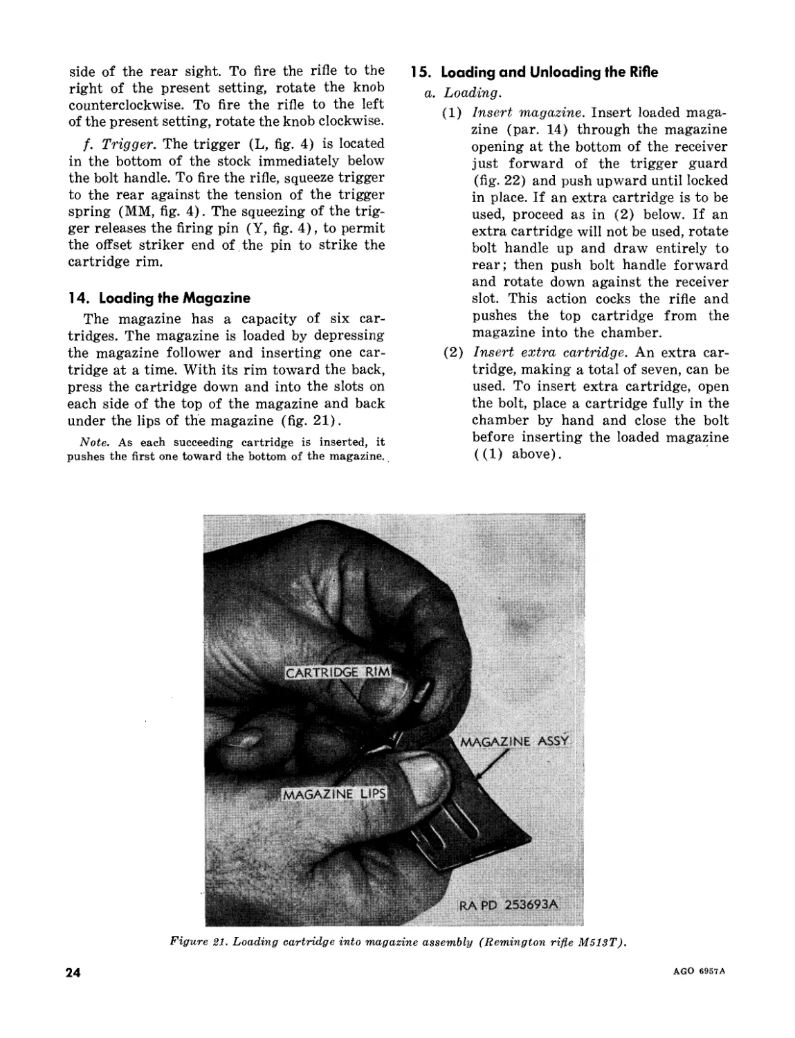
JULY 1958
This technical manual is correct to 2 June 1958
Technical Manual
No. 9-1005-206-12
*TM 9-1005-206-12
HEADQUARTERS,
DEPARTMENT OF THE ARMY
Washington 25, D. C., 15 July 1958
CALIBER .22 RIFLE M13:
REMINGTON RIFLE M513T,
STEVENS RIFLE M416-2T,
AND
WINCHESTER RIFLE M75T
Chapter 1. INTRODUCTION
Paragraphs Page
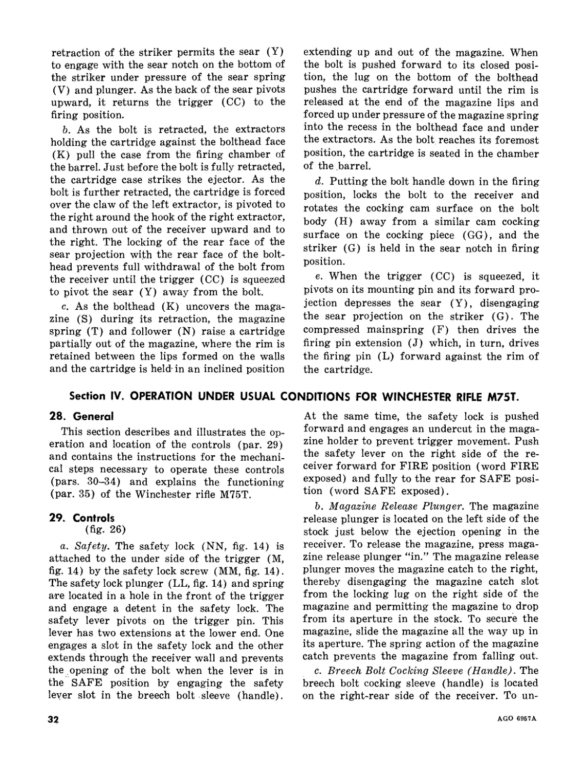
Section I. General________________________________________________________________________________
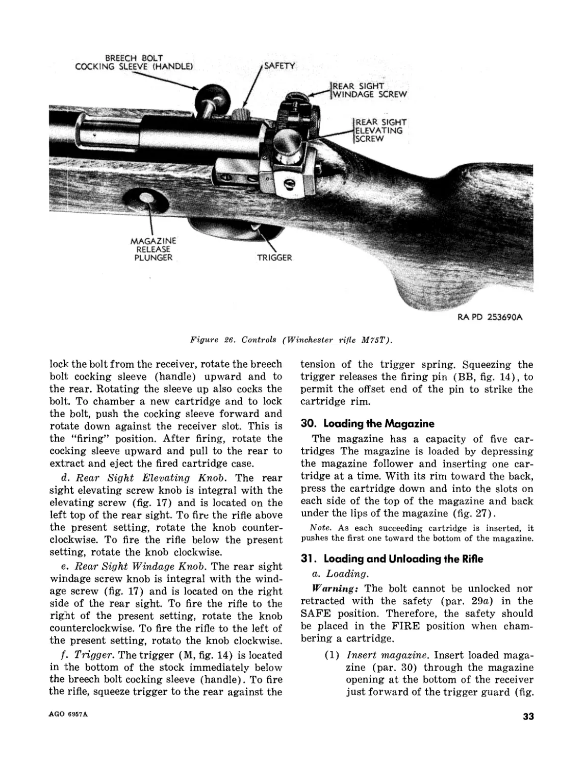
II. Description and data________________________________________________________________
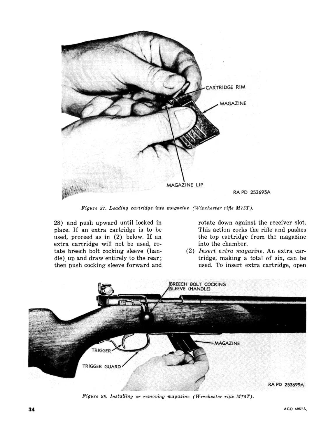
1-3 2
4-7 4
Chapter 2. OPERATING INSTRUCTIONS
Section I. Service upon receipt of materiel____________________________________________________
8-11 22
II. Operation under usual conditions for Remington rifle M513T_____________________________ 12-19 22
III. Operation under usual conditions for Stevens rifle M416-2T______________________________ 20-27 22
IV. Operation under usual conditions for Winchester rifle M75T------------------------------- 28-35 32
V. Operation under unusual conditions_______________________________________________________ 36-39 37
Chapter 3. ORGANIZATIONAL MAINTENANCE INSTRUCTIONS
Section I. Parts, special tools, and equipment_________________________________________
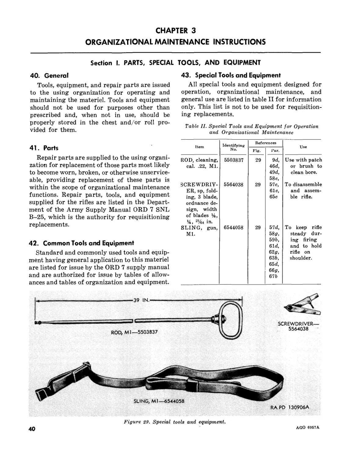
40-43 40
II. Lubrication _______________________________________________________________________ 44-47 41
III. Preventive-maintenance services_________________________________________________ 48-52 42
IV. Troubleshooting___________________________________________________________________ 53-55 45
V. Cal. .22 Remington rifle M513T_____________________________________________
VI. Cal. .22 Stevens rifle M416-2T----------------------------------------------
VII. Cal. .22 Winchester rifle M75T_______________________________________________
56-59 46
60-63 51
64-67 57
VIII. Maintenance under unusual conditions________________________________________ 68, 69 63
Chapter 4. AMMUNITION __________________________________________ 70-77 64
Chapter 5. SHIPMENT AND STORAGE AND DESTRUCTION TO
PREVENT ENEMY USE
Section I. Shipment and Storage______________________________________________________ 78-80 67
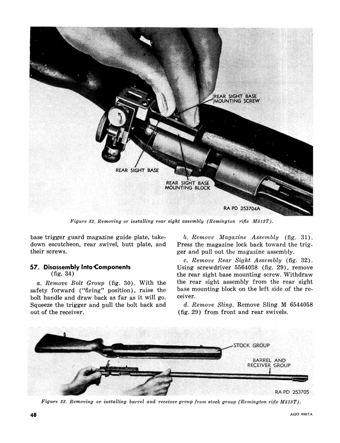
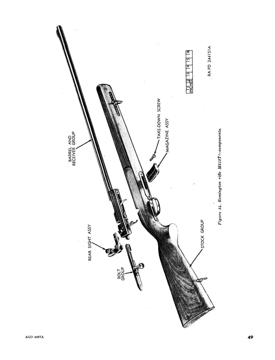
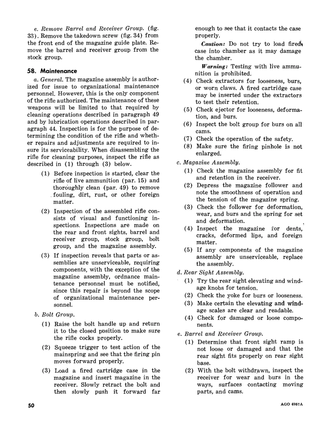
II. Destruction of materiel to prevent enemy use_______________________________________ 81, 82 68
Appendix. REFERENCES ________________________________________ _____ 70
Index ________________________________________________________________________________
♦This manual supersedes TM 9-280, 16 March 1944, and ТВ 9-280-1, 10 February 1949.
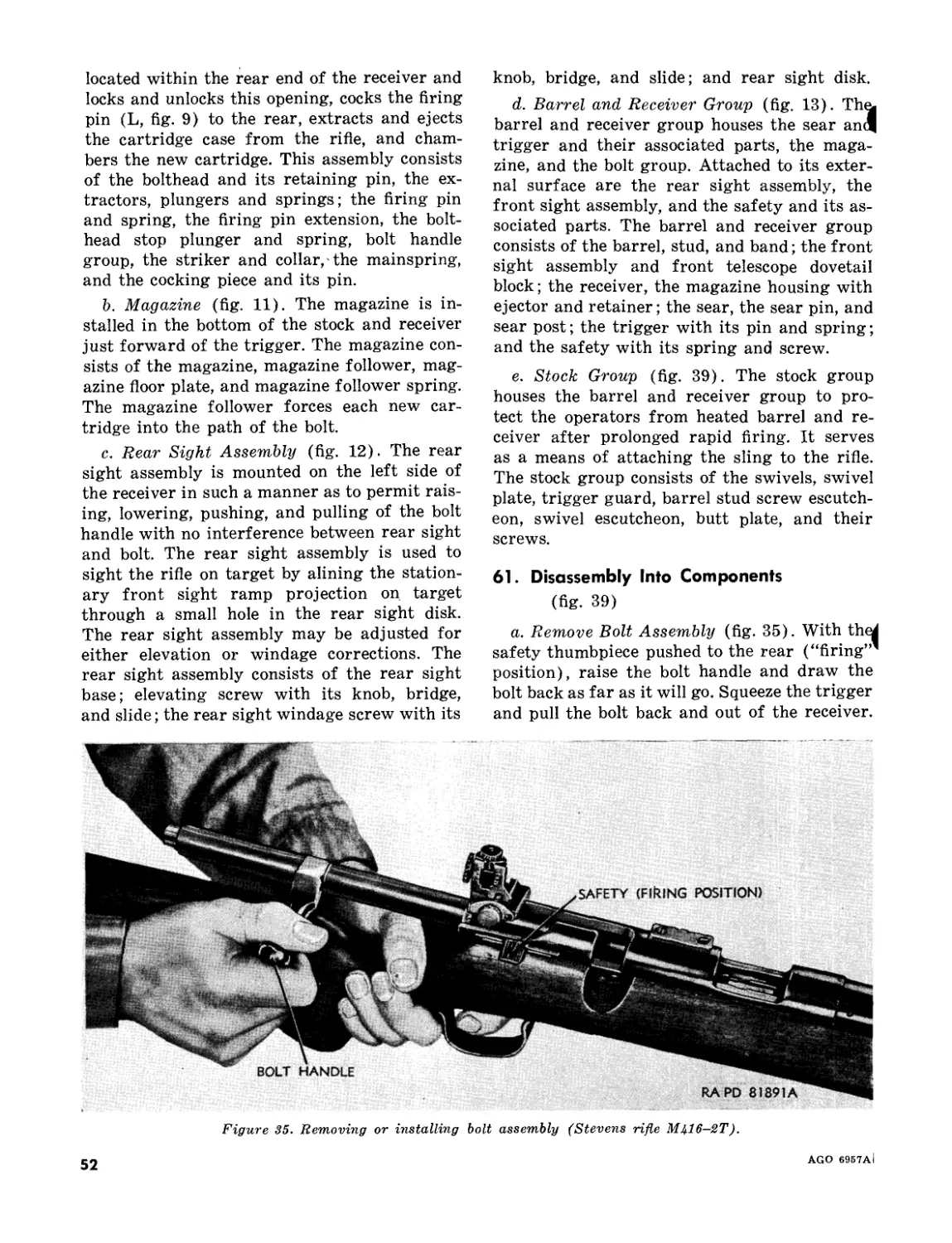
TAGO 6957А—Jun
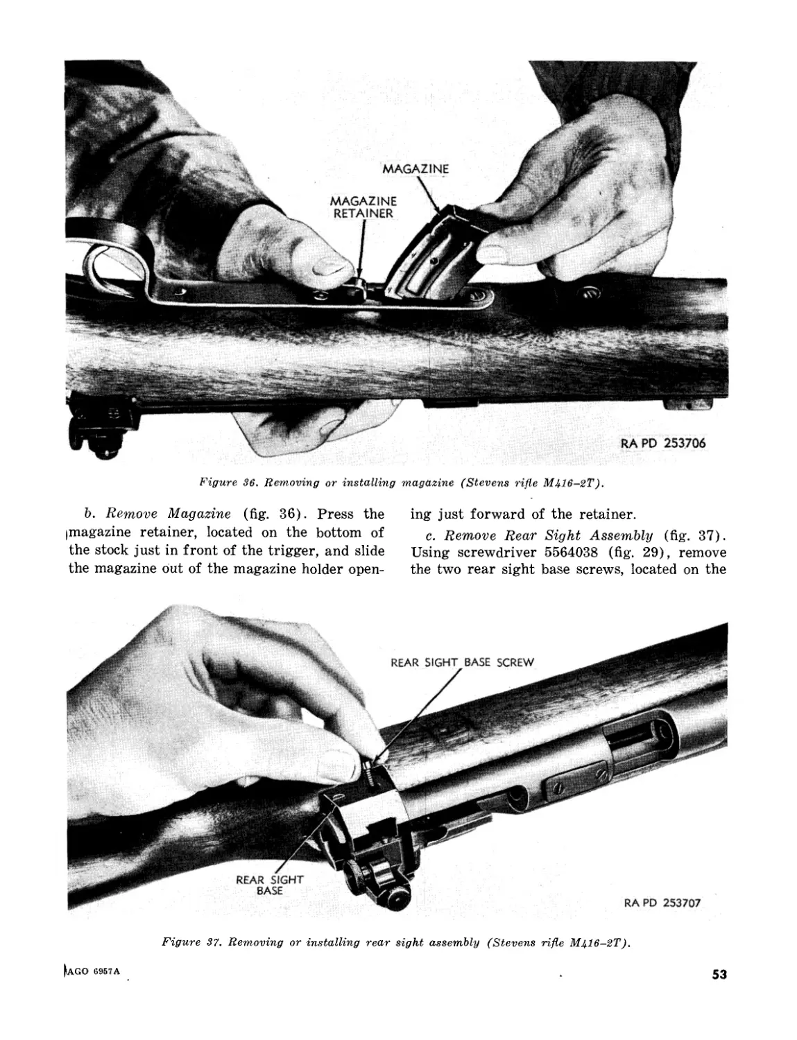
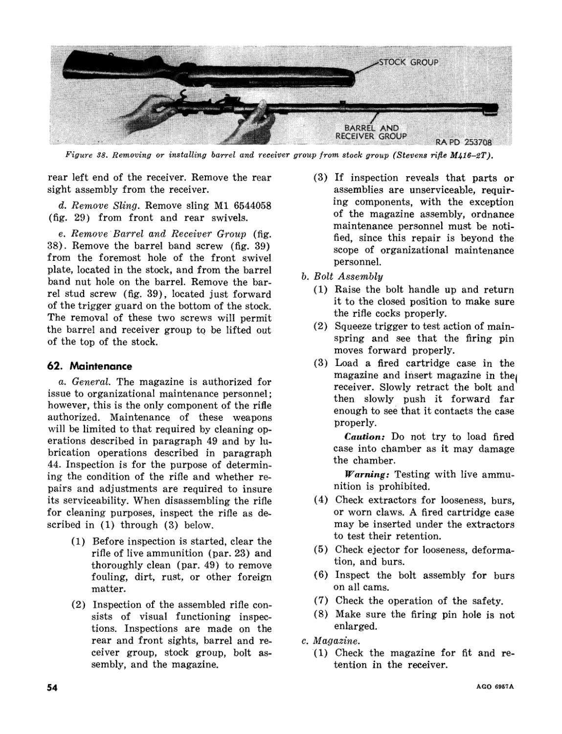
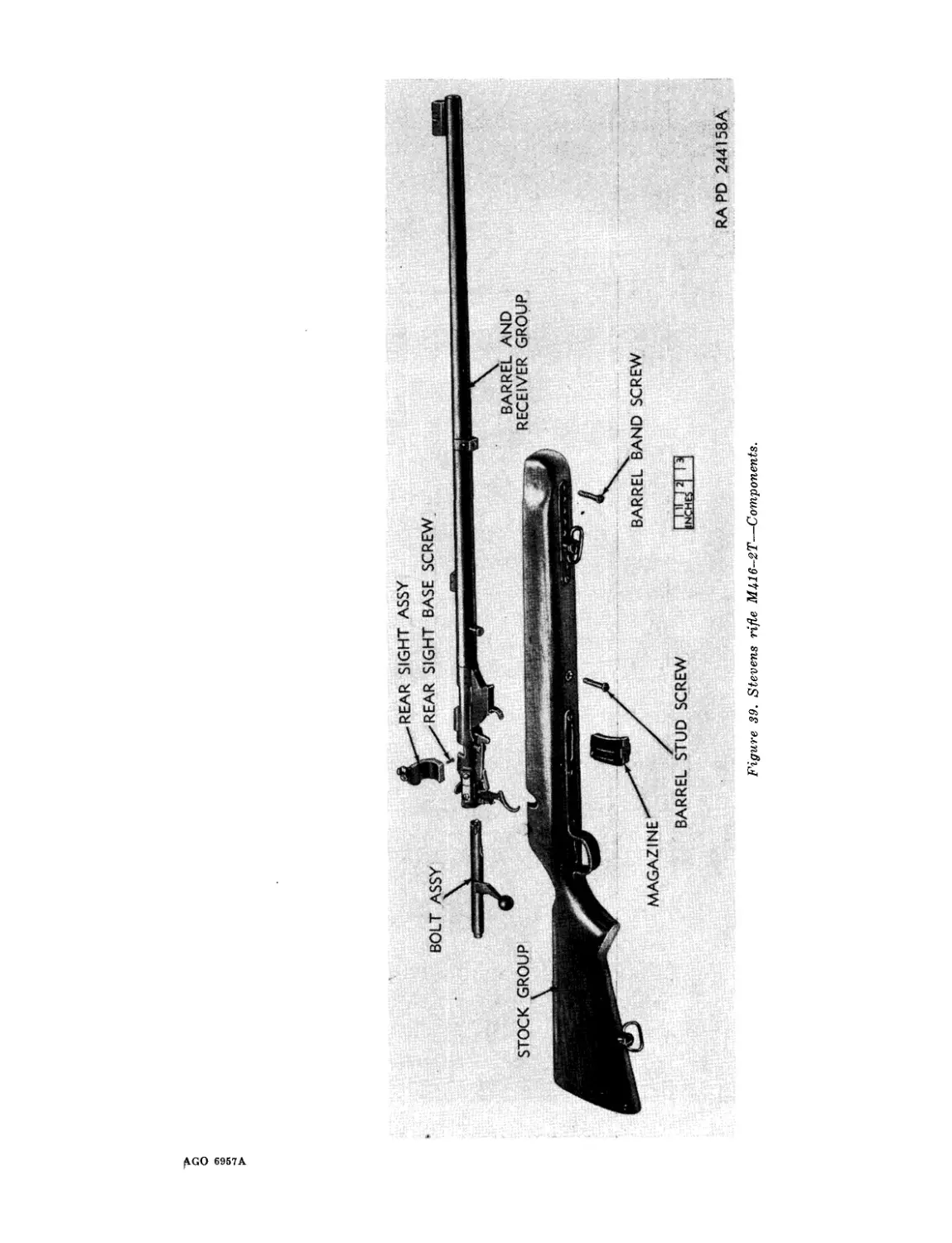
CHAPTER 1
INTRODUCTION
Section I. GENERAL
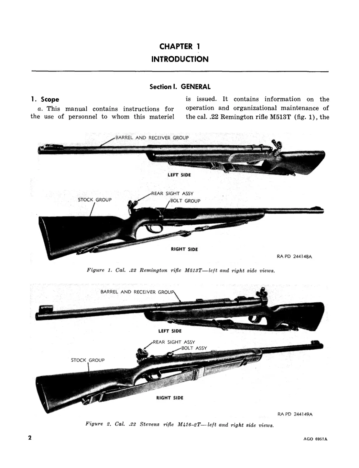
1. Scope
a. This manual contains instructions for
the use of personnel to whom this materiel
is issued. It contains information on the
operation and organizational maintenance of
the cal. .22 Remington rifle M513T (fig. 1), the
Figure 1. Cal. .22 Remington rifle M513T—left and right side views.
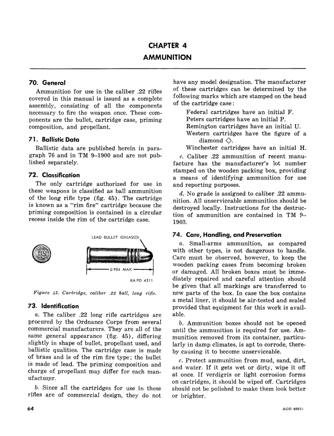
Figure 2. Cal. .22 Stevens rifle M416-2T—left and right side views.
2
AGO 6957A
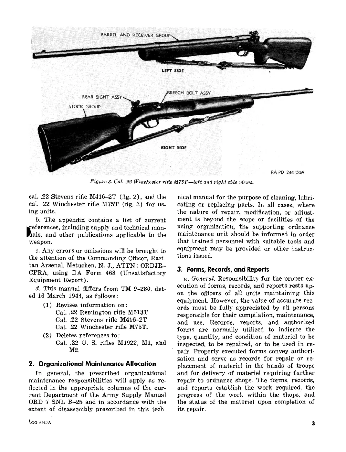
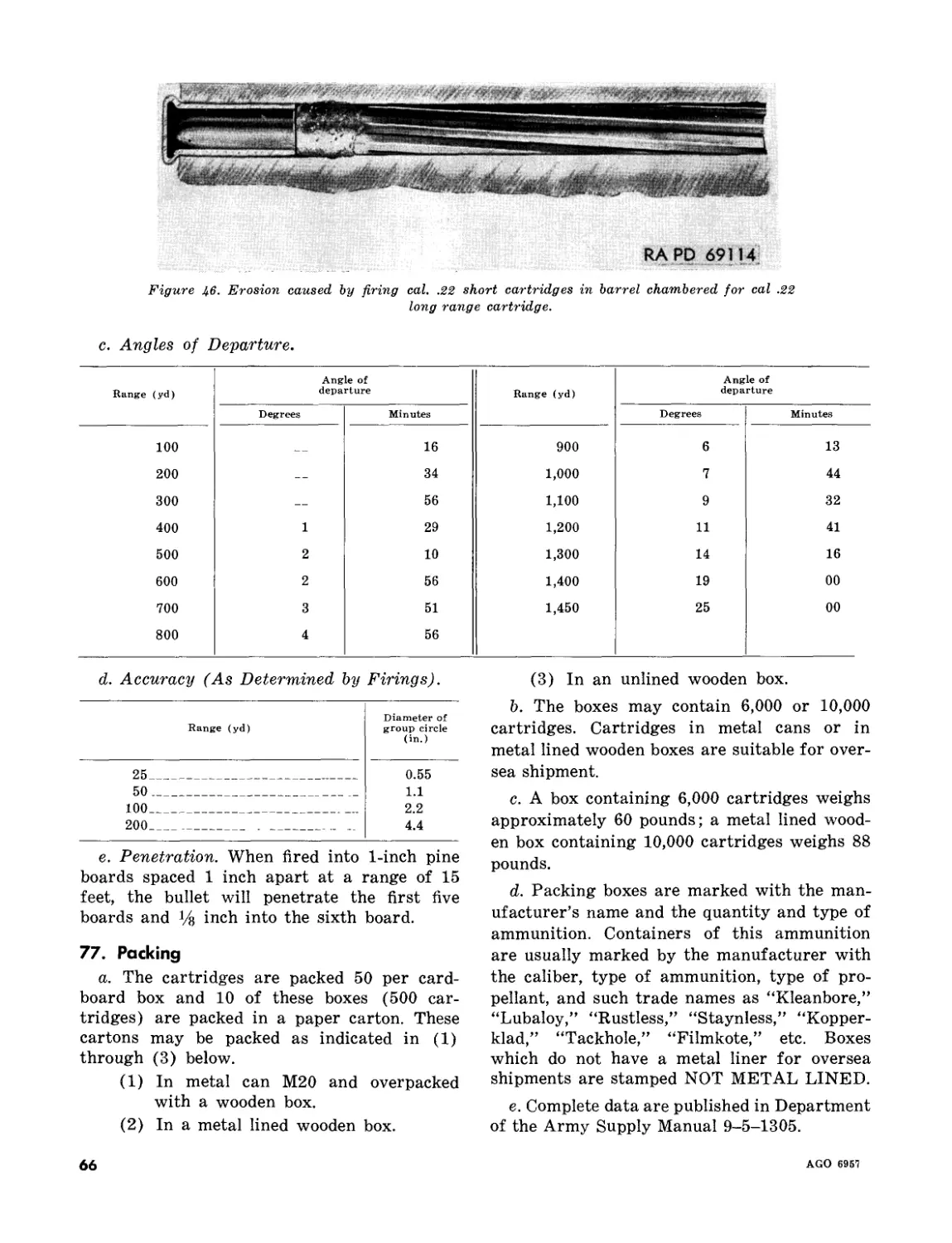
Figure 3. Cal. .22 Winchester rifle M75T—left and right side views.
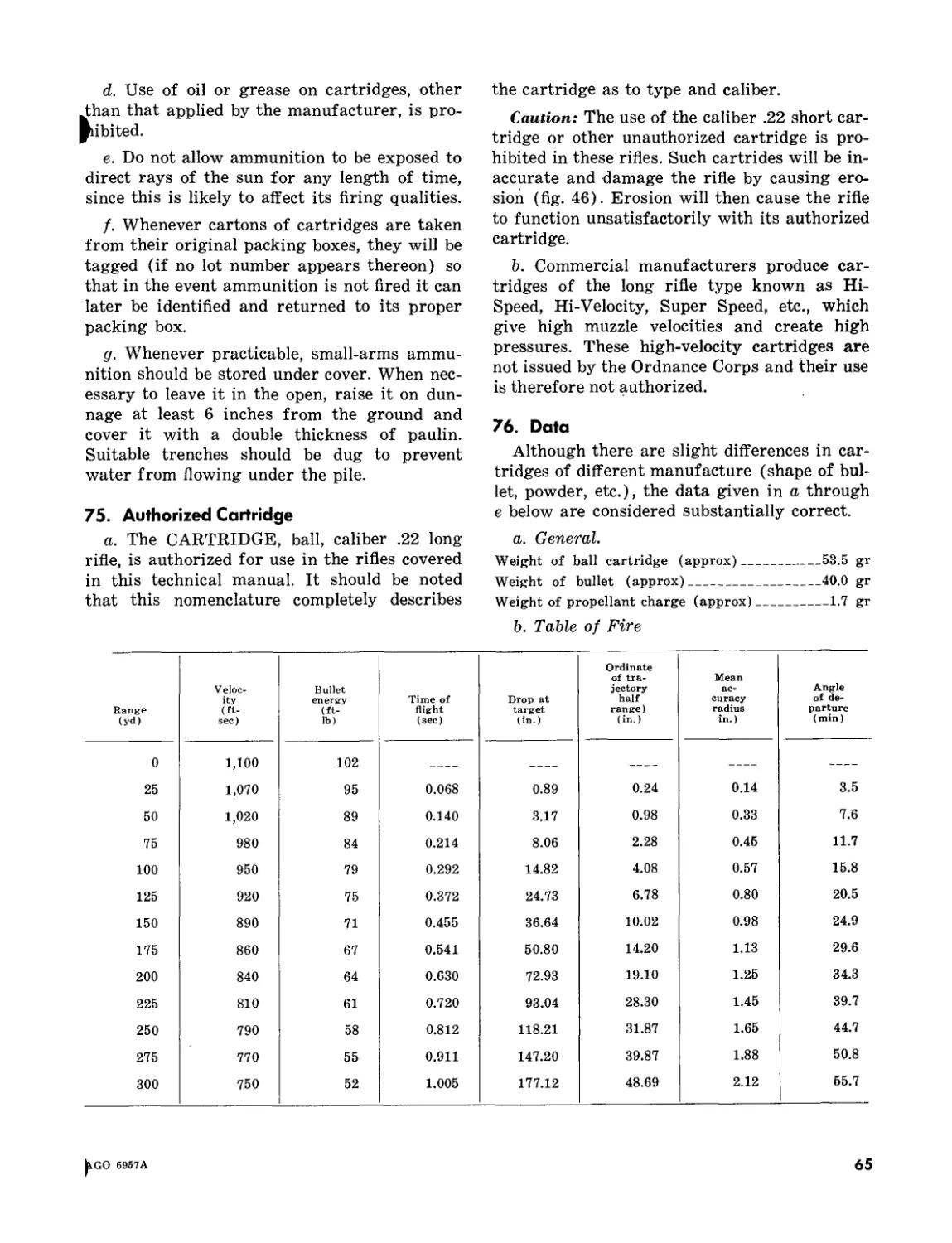
cal. .22 Stevens rifle M416-2T (fig. 2), and the
cal. .22 Winchester rifle M75T (fig. 3) for us-
ing units.
b. The appendix contains a list of current
«references, including supply and technical man-
uals, and other publications applicable to the
weapon.
c. Any errors or omissions will be brought to
the attention of the Commanding Officer, Rari-
tan Arsenal, Metuchen, N. J., ATTN: ORDJR-
CPRA, using DA Form 468 (Unsatisfactory
Equipment Report).
d. This manual differs from TM 9-280, dat-
ed 16 March 1944, as follows:
(1) Revises information on:
Cal. .22 Remington rifle M513T
Cal. .22 Stevens rifle M416-2T
Cal. .22 Winchester rifle M75T.
(2) Deletes references to:
Cal. .22 U. S. rifles M1922, Ml, and
М2.
2. Organizational Maintenance Allocation
In general, the prescribed organizational
maintenance responsibilities will apply as re-
flected in the appropriate columns of the cur-
rent Department of the Army Supply Manual
ORD 7 SNL B-25 and in accordance with the
extent bf disassembly prescribed in this tech-
nical manual for the purpose of cleaning, lubri-
cating or replacing parts. In all cases, where
the nature of repair, modification, or adjust-
ment is beyond the scope or facilities of the
using organization, the supporting ordnance
maintenance unit should be informed in order
that trained personnel with suitable tools and
equipment may be provided or other instruc-
tions issued.
3. Forms, Records, and Reports
a. General. Responsibility for the proper ex-
ecution of forms, records, and reports rests up-
on the officers of all units maintaining this
equipment. However, the value of accurate rec-
ords must be fully appreciated by all persons
responsible for their compilation, maintenance,
and use. Records, reports, and authorized
forms are normally utilized to indicate the
type, quantity, and condition of materiel to be
inspected, to be repaired, or to be used in re-
pair. Properly executed forms convey authori-
zation and serve as records for repair or re-
placement of materiel in the hands of troops
and for delivery of materiel requiring further
repair to ordnance shops. The forms, records,
and reports establish the work required, the
progress of the work within the shops, and
the status of the materiel upon completion of
its repair.
Igo 6967A
3
b. Authorized Forms. The forms generally
applicable to units operating and maintaining
this materiel are listed in the appendix. For a
listing of all forms, refer to DA Pam 310-2.
For instructions on the use of these forms, re-
fer to FM 9-10.
c. Field Report of Accidents.
(1) Injury to personnel or damage to ma-
teriel. The reports necessary to com-
ply with the requirements of the Army
safety program are prescribed in de-
tail in AR 385-40. These reports are
required whenever accidents involv-
ing injury to personnel or damage to
materiel occur.
(2) Ammunition. Whenever an accident
or malfunction involving the use ob
ammunition occurs, firing of the lo^
which malfunctions will be immediate-
ly discontinued. In addition to any
applicable reports required in (1)
above, details of the accident or mal-
function will be reported as prescribed
in AR 700-1300-8.
d. Report of Unsatisfactory Equipment or
Materials. Any deficiencies detected in the
equipment covered herein, which occur under
the circumstances indicated in AR 700-38,
should be immediately reported in accordance
with the applicable instructions in cited regu-
lations.
Section II. DESCRIPTION AND DATA
4. Description
a. General.
(1) These rifles are procured to provide
an accurate small-bore weapon for
training purposes. Three types of com-
mercial rifles are covered by this tech-
nical manual and are listed in para-
graph la.
(2) These rifles are bolt operated and
magazine-fed. The magazine will hold
either 5 or 6 cartridges and one addi-
tional cartridge may be inserted into
the chamber, making a maximum ca-
pacity for any one loading of 6 or 7
shots. A cartridge is ejected and a
new one inserted into the chamber by
drawing the bolt back and pushing it
closed again. The rear sights are ad-
justable for both windage and eleva-
tion.
(3) Each of the cal. .22 rifles may be dis-
assembled into five groups and/or as-
semblies : the bolt group or assembly;
the magazine assembly or magazine;
the rear sight assembly; the barrel and
receiver group; and the stock group.
Nomenclature of like parts, assem-
blies, or groups with similar functions
composing the three distinct rifles cov-
ered in this technical manual vary
somewhat. For example, the bolt
groups are designated as groups or
assemblies to agree with the listing
in the supply manual pertaining to the
rifle.
(4) The bolt group of the Remington rifle
M513T is not designated as an assem-
bly in the supply manual and is there-
fore called a group in this technical
manual. The bolt group of the Stevens
rifle M416-2T is termed “bolt assem-
bly,” that of the Winchester rifld
M75T is referred to as “breech bolr
assembly.”
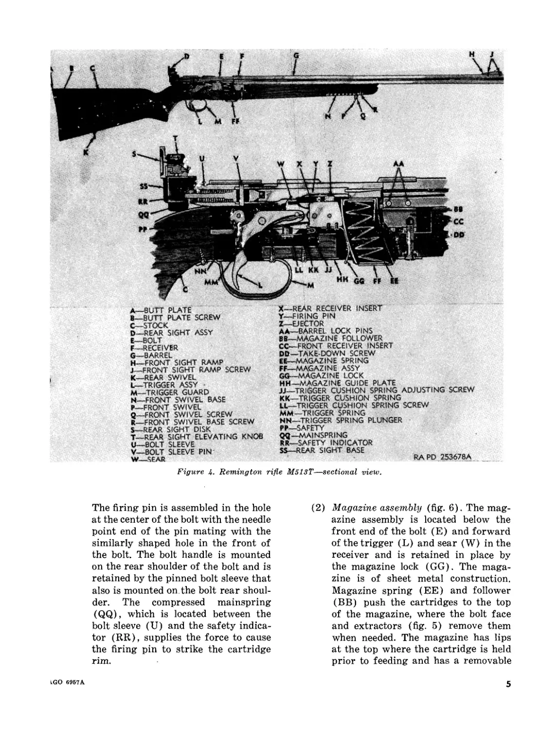
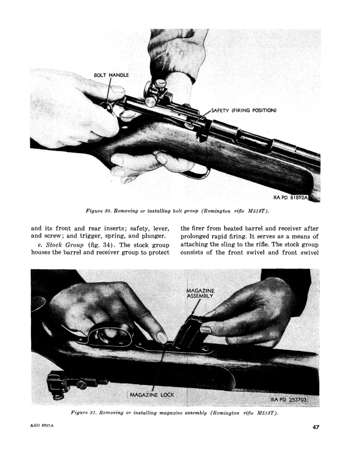
b. Remington Rifle M513T (fig. 4). The Rem-
ington rifle M513T (figs. 1 and 34) consists
basically of a bolt group, magazine assembly, a
rear sight assembly, a barrel and receiver group,
and a stock group.
Note. The key letters shown below in parentheses
refer to figure 4.
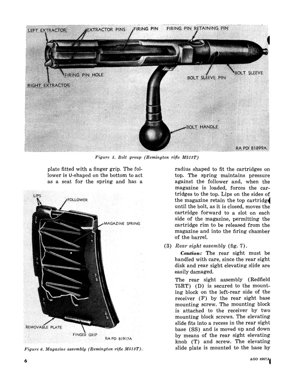
(1) Bolt group (fig. 5). The extractors are
mounted on each side of the forward
end of the bolt in two machined slots.
They are retained there by two extrac-
tor pins passing through their centers
and are operated by one extractor
spring passing vertically through the
bolt and pushing the rear of each ex-
tractor outward and forcing their
front ends inward. The bolt (E) and
firing pin (Y) are pinned together by
the firing pin retaining pin but the
firing pin retaining pin hole in the bolt
is elongated to permit the firing pin
to move back and forth inside the bolt.
4
AGO 6957^
A—BUTT PLATE
B—BUTT PLATE SCREW
G__STOCK
D—REAR SIGHT ASSY
E—BOLT
F—RECEIVER
G—BARREL
H—FRONT SIGHT RAMP
j_FRONT SIGHT RAMP SCREW
K—REAR SWIVEL
L—TRIGGER ASSY
M—TRIGGER GUARD
N—FRONT SWIVEL BASE
P—FRONT SWIVEL
Q—FRONT SWIVEL SCREW
R—FRONT SWIVEL BASE SCREW
S—REAR SIGHT DISK
T—REAR SIGHT ELEVATING KNOB
U—BOLT SLEEVE
V—BOLT SLEEVE PIN
W—SEAR
X—REAR RECEIVER INSERT
Y—FIRING PIN
Z—EJECTOR
AA—BARREL LOCK PINS
BB—MAGAZINE FOLLOWER
CC—FRONT RECEIVER INSERT
OD—TAKE-DOWN SCREW
EE—MAGAZINE SPRING
FF—MAGAZINE ASSY
GG—MAGAZINE LOCK
HH—MAGAZINE GUIDE PLATE
JJ—TRIGGER CUSHION SPRING ADJUSTING SCREW
KK—TRIGGER CUSHION SPRING
LL—TRIGGER CUSHION SPRING SCREW
MM—TRIGGER SPRING
MN—TRIGGER SPRING PLUNGER
PP—SAFETY
QQ—MAINSPRING
RR—SAFETY INDICATOR
SS—REAR SIGHT BASE
RAPD 253678A
Figure k. Remington rifle M513T—sectional view.
The firing pin is assembled in the hole
at the center of the bolt with the needle
point end of the pin mating with the
similarly shaped hole in the front of
the bolt. The bolt handle is mounted
on the rear shoulder of the bolt and is
retained by the pinned bolt sleeve that
also is mounted on. the bolt rear shoul-
der. The compressed mainspring
(QQ), which is located between the
bolt sleeve (U) and the safety indica-
tor (RR), supplies the force to cause
the firing pin to strike the cartridge
rim.
(2) Magazine assembly (fig. 6). The mag-
azine assembly is located below the
front end of the bolt (E) and forward
of the trigger (L) and sear (W) in the
receiver and is retained in place by
the magazine lock (GG). The maga-
zine is of sheet metal construction.
Magazine spring (EE) and follower
(BB) push the cartridges to the top
of the magazine, where the bolt face
and extractors (fig. 5) remove them
when needed. The magazine has lips
at the top where the cartridge is held
prior to feeding and has a removable
LGO 6957A
5
Figure 5. Bolt group (Remington rifle M513T)
plate fitted with a finger grip. The fol-
lower is U-shaped on the bottom to act
as a seat for the spring and has a
LIPS
FINGER GRIP
RA PD 8I9I7A
Figure 6. Magazine assembly (Remington rifle M513T).
radius shaped to fit the cartridges on
top. The spring maintains pressure
against the follower and, when the
magazine is loaded, forces the car-
tridges to the top. Lips on the sides of
the magazine retain the top cartridg^
until the bolt, as it is closed, moves the
cartridge forward to a slot on each
side of the magazine, permitting the
cartridge rim to be released from the
magazine and into the firing chamber
of the barrel.
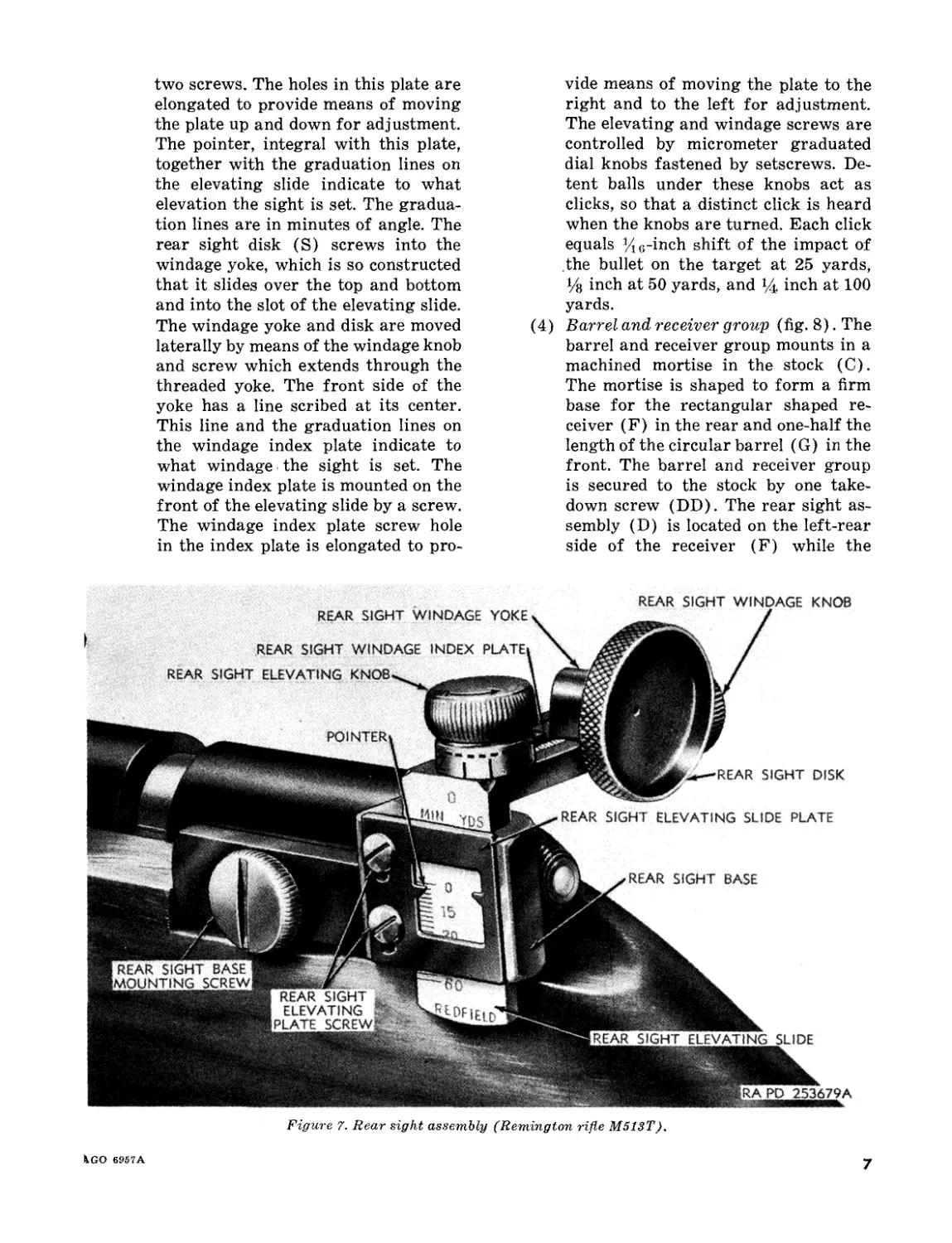
(3) Rear sight assembly (fig. 7).
Caution: The rear sight must be
handled with care, since the rear sight
disk and rear sight elevating slide are
easily damaged.
The rear sight assembly (Redfield
75RT) (D) is secured to the mount-
ing block on the left-rear side of the
receiver (F) by the rear sight base
mounting screw. The mounting block
is attached to the receiver by two
mounting block screws. The elevating
slide fits into a recess in the rear sight
base (SS) and is moved up and down
by means of the rear sight elevating
knob (T) and screw. The elevating
slide plate is mounted to the base by
6
AGO 6957.
two screws. The holes in this plate are
elongated to provide means of moving
the plate up and down for adjustment.
The pointer, integral with this plate,
together with the graduation lines on
the elevating slide indicate to what
elevation the sight is set. The gradua-
tion lines are in minutes of angle. The
rear sight disk (S) screws into the
windage yoke, which is so constructed
that it slides over the top and bottom
and into the slot of the elevating slide.
The windage yoke and disk are moved
laterally by means of the windage knob
and screw which extends through the
threaded yoke. The front side of the
yoke has a line scribed at its center.
This line and the graduation lines on
the windage index plate indicate to
what windage the sight is set. The
windage index plate is mounted on the
front of the elevating slide by a screw.
The windage index plate screw hole
in the index plate is elongated to pro-
vide means of moving the plate to the
right and to the left for adjustment.
The elevating and windage screws are
controlled by micrometer graduated
dial knobs fastened by setscrews. De-
tent balls under these knobs act as
clicks, so that a distinct click is heard
when the knobs are turned. Each click
equals '/jo-inch shift of the impact of
the bullet on the target at 25 yards,
Уз inch at 50 yards, and inch at 100
yards.
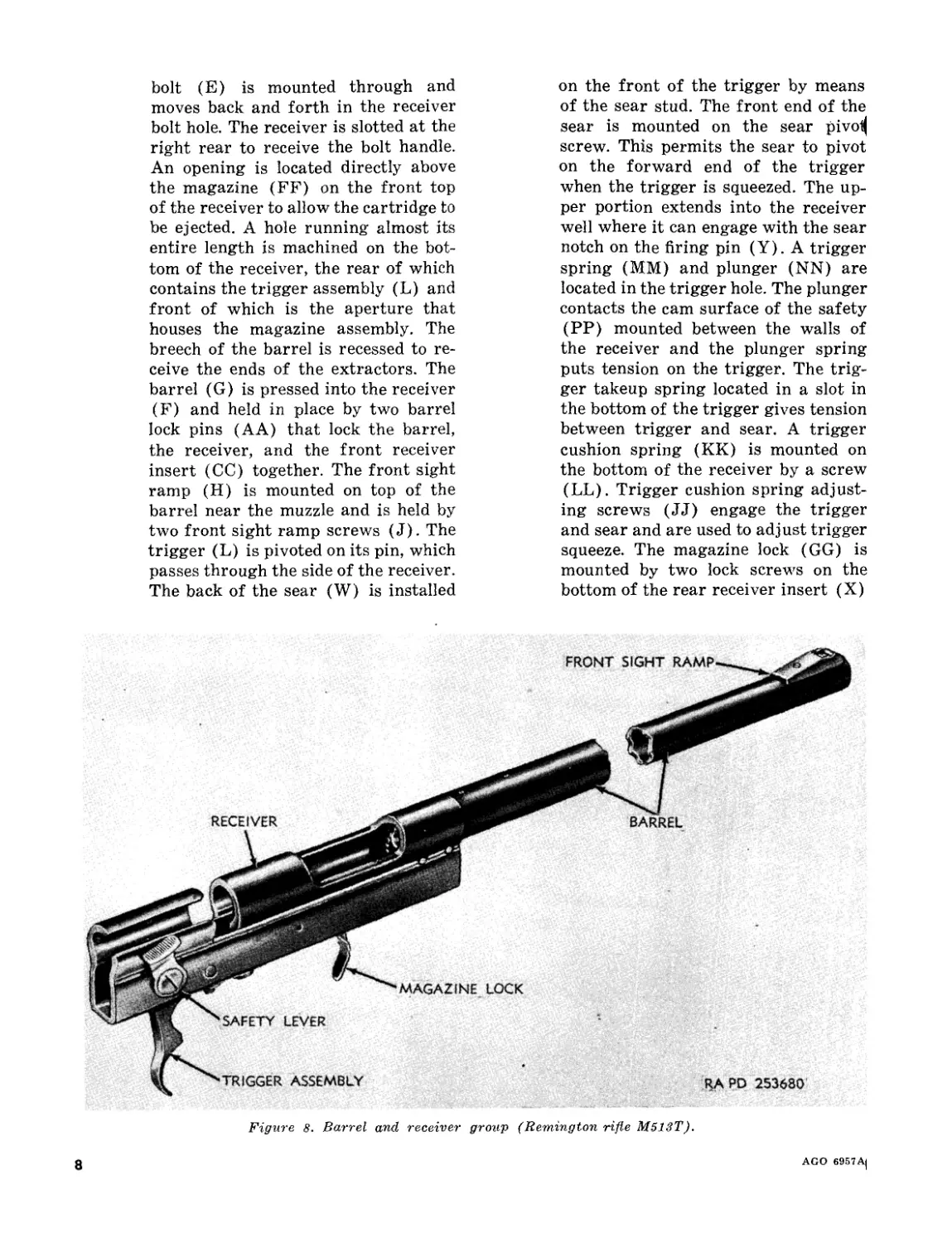
(4) Barrel and receiver group (fig. 8). The
barrel and receiver group mounts in a
machined mortise in the stock (C).
The mortise is shaped to form a firm
base for the rectangular shaped re-
ceiver (F) in the rear and one-half the
length of the circular barrel (G) in the
front. The barrel and receiver group
is secured to the stock by one take-
down screw (DD). The rear sight as-
sembly (D) is located on the left-rear
side of the receiver (F) while the
POINTER
REAR SIGHT ELEVATING SLI DE
'RAPP 253679A
REAR SIGHT WINDAGE YOKE
REAR SIGHT WINDAGE INDEX PLATE,
REAR SIGHT ELEVATING KNOB
REAR SIGHT WINDAGE KNOB
[REAR SIGHT BASE I
[MOUNTING SCREW,
REAR SIGHT
ELEVATING
PLATE SCREWS
REAR
REAR SIGHT DISK
SIGHT ELEVATING SLIDE PLATE
REAR SIGHT BASE
Figure 7. Rear sight assembly (Remington rifle M513T).
ico 6957A
7
bolt (E) is mounted through and
moves back and forth in the receiver
bolt hole. The receiver is slotted at the
right rear to receive the bolt handle.
An opening is located directly above
the magazine (FF) on the front top
of the receiver to allow the cartridge to
be ejected. A hole running almost its
entire length is machined on the bot-
tom of the receiver, the rear of which
contains the trigger assembly (L) and
front of which is the aperture that
houses the magazine assembly. The
breech of the barrel is recessed to re-
ceive the ends of the extractors. The
barrel (G) is pressed into the receiver
(F) and held in place by two barrel
lock pins (AA) that lock the barrel,
the receiver, and the front receiver
insert (CO) together. The front sight
ramp (H) is mounted on top of the
barrel near the muzzle and is held by
two front sight ramp screws (J). The
trigger (L) is pivoted on its pin, which
passes through the side of the receiver.
The back of the sear (W) is installed
on the front of the trigger by means
of the sear stud. The front end of the
sear is mounted on the sear pivoi|
screw. This permits the sear to pivot
on the forward end of the trigger
when the trigger is squeezed. The up-
per portion extends into the receiver
well where it can engage with the sear
notch on the firing pin (Y). A trigger
spring (MM) and plunger (NN) are
located in the trigger hole. The plunger
contacts the cam surface of the safety
(PP) mounted between the walls of
the receiver and the plunger spring
puts tension on the trigger. The trig-
ger takeup spring located in a slot in
the bottom of the trigger gives tension
between trigger and sear. A trigger
cushion spring (KK) is mounted on
the bottom of the receiver by a screw
(LL). Trigger cushion spring adjust-
ing screws (JJ) engage the trigger
and sear and are used to adjust trigger
squeeze. The magazine lock (GG) is
mounted by two lock screws on the
bottom of the rear receiver insert (X)
Figure 8. Barrel and receiver group (Remington rifle M513T).
8
AGO 69S7A(
and serves to retain the magazine in
position in the rifle. The ejector (Z)
is mounted in the bottom of the receiv-
er by means of the ejector screw and
the sear pivot screw. The sear pivot
screw passes through the pivot hole in
the sear, the ejector, and the rear re-
ceiver insert.
(5) Stock group. The stock (C) is cut out
at the top for the barrel (G) and re-
ceiver (F). The side is slotted to re-
ceive the bolt handle. The bottom is
mortised to receive the front swivel
base (N), the trigger (L), and the
magazine assembly (FF). The front
swivel (P) is secured to the front
swivel base by a front swivel screw
(Q). Seven tapped holes in the swivel
base (N) permit moving the swivel
for adjusting of the handhold with re-
lation to the sling. The rear swivel
(K) is screwed to the stock by a screw
which is integral with the swivel. The
magazine guide plate (HH) which
retains the barrel and the receiver in
the stock is attached to the stock by
one wood screw and one machine
screw. The trigger guard (M) is se-
cured to the stock by two wood screws.
The butt plate (A) is attached to the
rear of the stock with two butt plate
screws (B).
A—REAR SIGHT DISK ASSY
B—REAR SIGHT WINDAGE DOVETAIL SLIDE
C—-REAR SIGHT ELEVATING SCREW KNOB
D—REAR SIGHT WINDAGE SCREW KNOB
E—.REAR SIGHT WINDAGE SCREW KNOB CLICK
F—MAINSPRING
G—STRIKER
H—BOLT BODY
J—FIRING PIN EXTENSION
K—BOLT HEAD
L—FIRING PIN
M—FIRING PIN SPRING
N—-MAGAZINE FOLLOWER
P—MAGAZINE HOUSING SCREW
Q—MAGAZINE HOUSING W/EJECTOR
R—-TRIGGER GUARD LONG SCREW
S—MAGAZINE
T—MAGAZINE SPRING
U—MAGAZINE RETAINER
V—SEAR SPRING
W—SEAR POST
X—-SEAR STOP SCREW
Y—SEAR
Z—-TRIGGER GUARD SHORT SCREW
AA—TRIGGER SPRING
BB—TRIGGER SIDE PLAY SCREW
CC—-TRIGGER ASSY
DD—TRIGGER GUARD
EE—TRIGGER STOP PLUNGER
FF—TRIGGER STOP PLUNGER SPRING
GG—COCKING PIECE
RAP'D 253681A
Figure 9. Stevens rifle MJil6—2T—sectional view.
'AGO 6957A
9
c. Stevens Rifle Mfl6—2T (fig. 9). The Stev-
ens rifle M416-2T (figs. 2 and 39) consists
basically of the bolt assembly, the magazine,
the rear sight assembly, the barrel and receiver
group, and the stock group.
Note. The key letters shown below in parentheses
refer to figure 9.
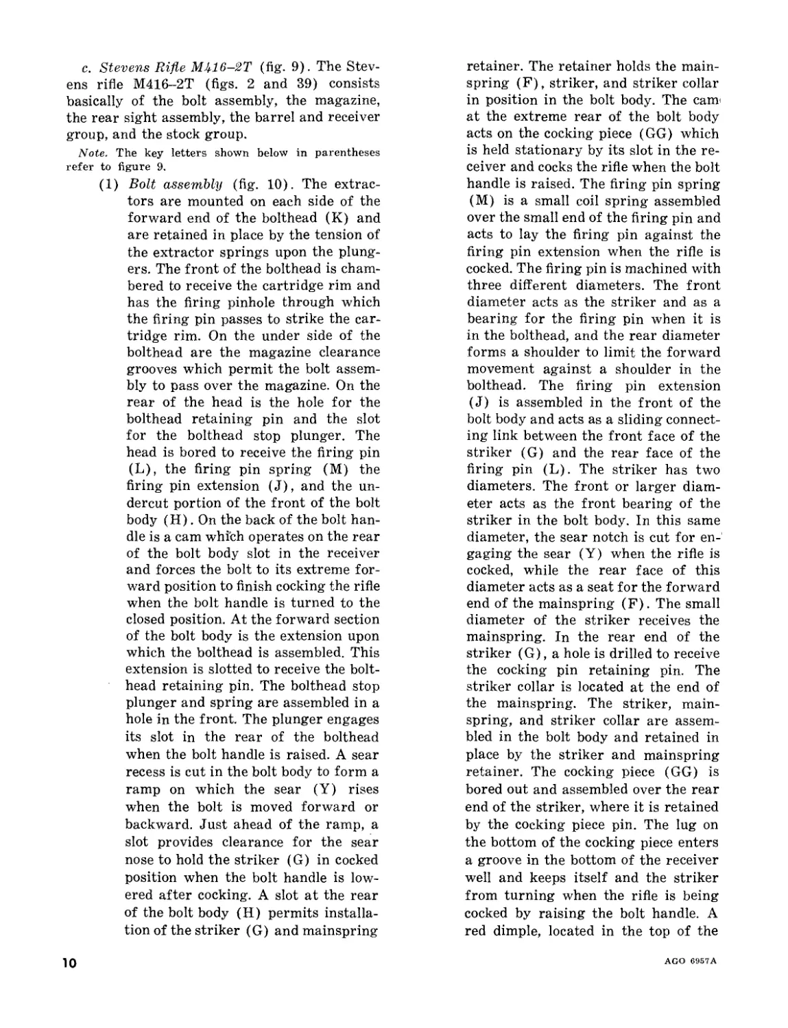
(1) Bolt assembly (fig. 10). The extrac-
tors are mounted on each side of the
forward end of the bolthead (K) and
are retained in place by the tension of
the extractor springs upon the plung-
ers. The front of the bolthead is cham-
bered to receive the cartridge rim and
has the firing pinhole through which
the firing pin passes to strike the car-
tridge rim. On the under side of the
bolthead are the magazine clearance
grooves which permit the bolt assem-
bly to pass over the magazine. On the
rear of the head is the hole for the
bolthead retaining pin and the slot
for the bolthead stop plunger. The
head is bored to receive the firing pin
(L), the firing pin spring (M) the
firing pin extension (J), and the un-
dercut portion of the front of the bolt
body (H). On the back of the bolt han-
dle is a cam which operates on the rear
of the bolt body slot in the receiver
and forces the bolt to its extreme for-
ward position to finish cocking the rifle
when the bolt handle is turned to the
closed position. At the forward section
of the bolt body is the extension upon
which the bolthead is assembled. This
extension is slotted to receive the bolt-
head retaining pin. The bolthead stop
plunger and spring are assembled in a
hole in the front. The plunger engages
its slot in the rear of the bolthead
when the bolt handle is raised. A sear
recess is cut in the bolt body to form a
ramp on which the sear (Y) rises
when the bolt is moved forward or
backward. Just ahead of the ramp, a
slot provides clearance for the sear
nose to hold the striker (G) in cocked
position when the bolt handle is low-
ered after cocking. A slot at the rear
of the bolt body (H) permits installa-
tion of the striker (G) and mainspring
retainer. The retainer holds the main-
spring (F), striker, and striker collar
in position in the bolt body. The сайт
at the extreme rear of the bolt body
acts on the cocking piece (GG) which
is held stationary by its slot in the re-
ceiver and cocks the rifle when the bolt
handle is raised. The firing pin spring
(M) is a small coil spring assembled
over the small end of the firing pin and
acts to lay the firing pin against the
firing pin extension when the rifle is
cocked. The firing pin is machined with
three different diameters. The front
diameter acts as the striker and as a
bearing for the firing pin when it is
in the bolthead, and the rear diameter
forms a shoulder to limit the forward
movement against a shoulder in the
bolthead. The firing pin extension
(J) is assembled in the front of the
bolt body and acts as a sliding connect-
ing link between the front face of the
striker (G) and the rear face of the
firing pin (L). The striker has two
diameters. The front or larger diam-
eter acts as the front bearing of the
striker in the bolt body. In this same
diameter, the sear notch is cut for en-
gaging the sear (Y) when the rifle is
cocked, while the rear face of this
diameter acts as a seat for the forward
end of the mainspring (F). The small
diameter of the striker receives the
mainspring. In the rear end of the
striker (G), a hole is drilled to receive
the cocking pin retaining pin. The
striker collar is located at the end of
the mainspring. The striker, main-
spring, and striker collar are assem-
bled in the bolt body and retained in
place by the striker and mainspring
retainer. The cocking piece (GG) is
bored out and assembled over the rear
end of the striker, where it is retained
by the cocking piece pin. The lug on
the bottom of the cocking piece enters
a groove in the bottom of the receiver
well and keeps itself and the striker
from turning when the rifle is being
cocked by raising the bolt handle. A
red dimple, located in the top of the
10
AGO 6957A
BOLT BODY
COCKING PIECE
HEAD RETAINING PIN
HANDLE
RA PD 81903A
Figure 10. Bolt assembly (Stevens rifle M416-2T).
cocking piece, which is visible only
when the striker and cocking piece
move backward together into cocked
position, indicates that the firing mech-
anism is cocked.
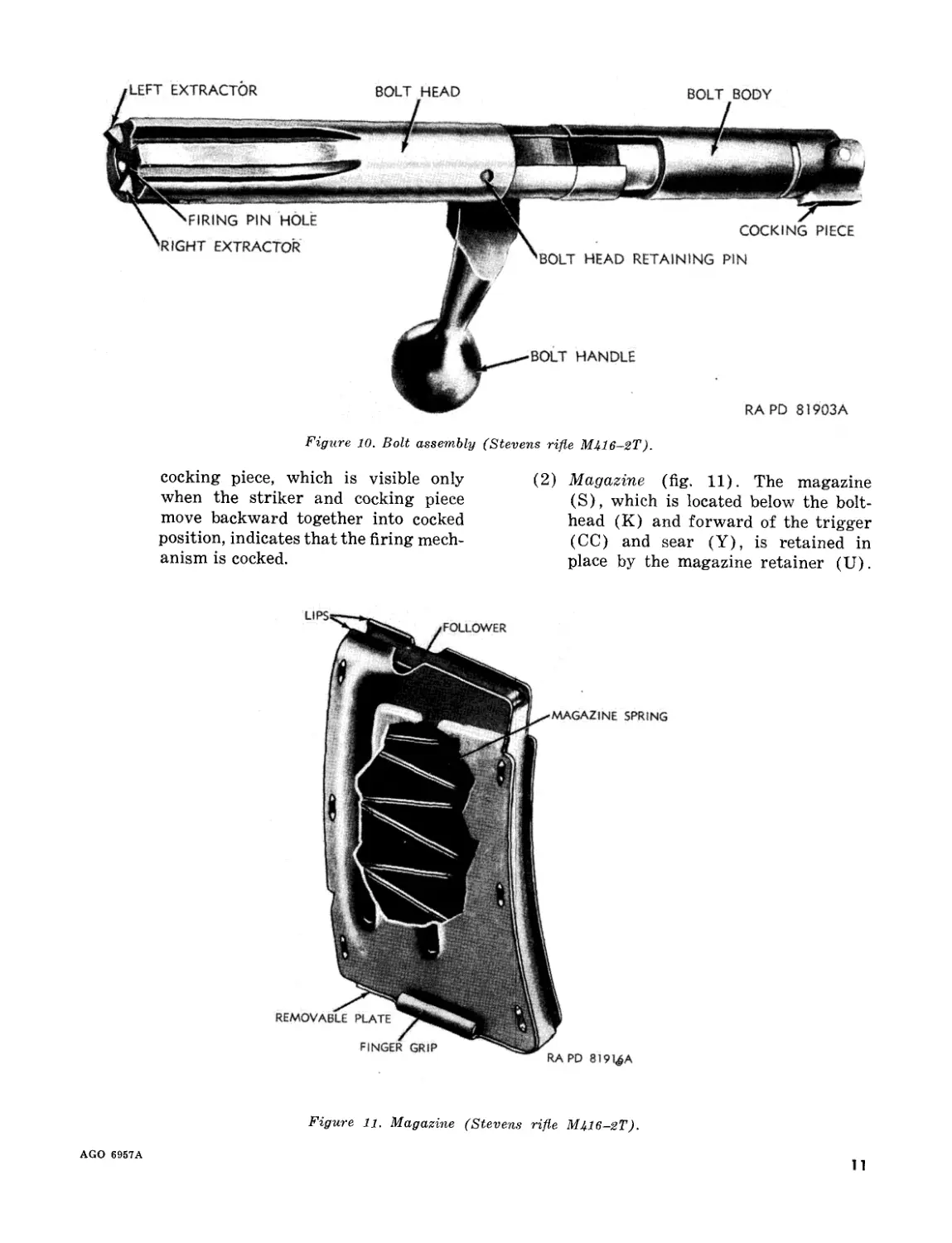
(2) Magazine (fig. 11). The magazine
(S), which is located below the bolt-
head (K) and forward of the trigger
(CC) and sear (Y), is retained in
place by the magazine retainer (U).
Figure 11. Magazine (Stevens rifle МЦ6-2Т).
AGO 6957A
11
The magazine is of sheet metal con-
struction. The magazine spring (T)
and the follower (N) push the car-
tridges to the top of the magazine,
where the bolthead face and extractors
(fig. 10) remove them when needed.
The magazine has lips at the top to
hold the next cartridge to be fired. The
magazine has a removable plate fitted
with finger grips. The follower is
U-shaped at the bottom to act as a seat
for the spring and has a radius shaped
to fit the cartridge on top. The spring
(T) maintains pressure against the
follower (N) and, when the magazine
is loaded, forces the cartridge to the
top. Lips on the top of the magazine
retain the top cartridge until the bolt,
as it is closed, moves the cartridge for-
ward to a slot on each side of the mag-
azine and into the firing chamber of
the barrel.
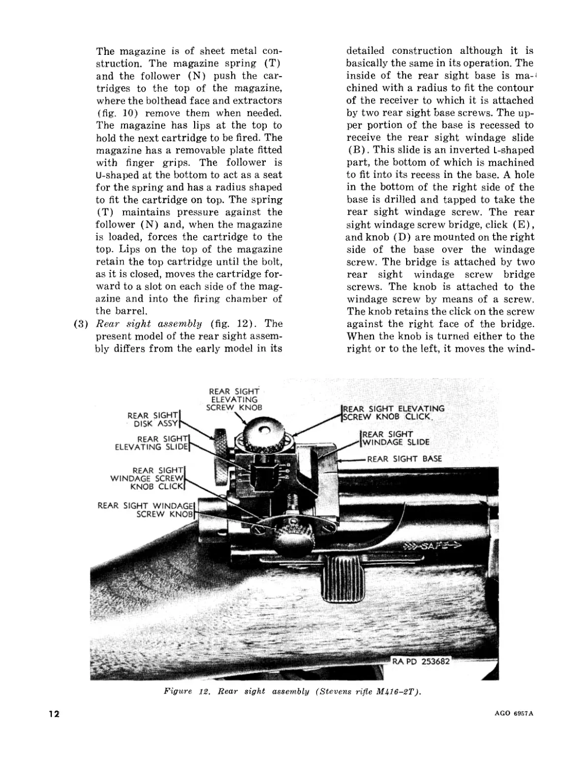
(3) Rear sight assembly (fig. 12). The
present model of the rear sight assem-
bly differs from the early model in its
detailed construction although it is
basically the same in its operation. The
inside of the rear sight base is ma-
chined with a radius to fit the contour
of the receiver to which it is attached
by two rear sight base screws. The up-
per portion of the base is recessed to
receive the rear sight windage slide
(B). This slide is an inverted L-shaped
part, the bottom of which is machined
to fit into its recess in the base. A hole
in the bottom of the right side of the
base is drilled and tapped to take the
rear sight windage screw. The rear
sight windage screw bridge, click (E),
and knob (D) are mounted on the right
side of the base over the windage
screw. The bridge is attached by two
rear sight windage screw bridge
screws. The knob is attached to the
windage screw by means of a screw.
The knob retains the click on the screw
against the right face of the bridge.
When the knob is turned either to the
right or to the left, it moves the wind-
Figure 12. Rear sight assembly (Stevens rifle MJ+16-2T).
A.G,Q 6957A
age slide by means of the windage
screw. When the knob is turned, a dis-
tinct “click” is heard, as there are six
small grooves cut in the left face of
the knob which engage the click. The
upper portion of the windage slide is
slotted to receive the rear sight elevat-
ing slide, which is grooved to fit into
and over the slot. The back of the ele-
vating slide is drilled and tapped to
receive the rear sight disk assembly
(A) and the top is drilled and tapped
to receive the rear sight elevating
screw. The elevating slide moves up
and down when the elevating screw is
rotated by means of the rear sight
elevating screw knob (C), the eleva-
tion being indicated on the right side
of the windage slide. The rear sight
elevating screw knob click, bridge, and
knob are mounted on top of the ele-
vating screw. The bridge is secured to
the windage slide by two rear sight
elevating screw bridge screws. The
knob is attached to the end of the ele-
vating screw by means of a rear sight
elevating screw knob screw. The knob
retains the click on the elevating screw
against the bridge. Six small grooves
cut in the bottom face of the knob con-
tact the raised portion of the click, so
that a distinct “click” is heard when
the knob is turned.
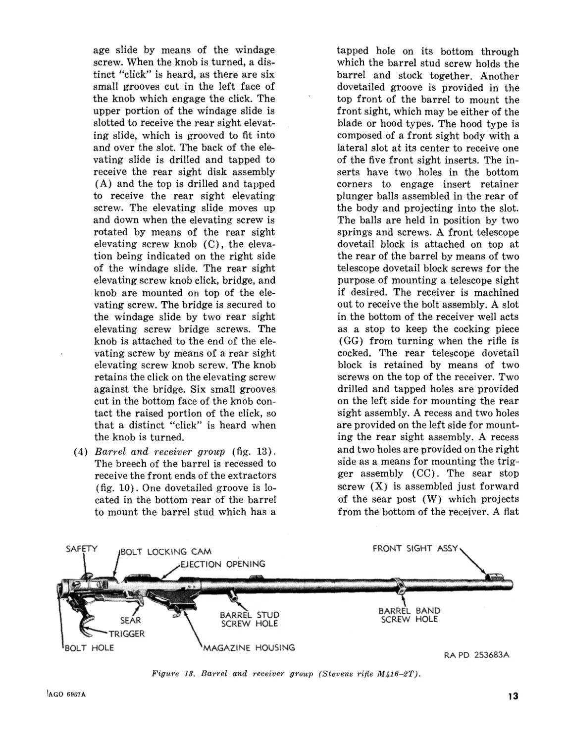
(4) Barrel and receiver group (fig. 13).
The breech of the barrel is recessed to
receive the front ends of the extractors
(fig. 10). One dovetailed groove is lo-
cated in the bottom rear of the barrel
to mount the barrel stud which has a
tapped hole on its bottom through
which the barrel stud screw holds the
barrel and stock together. Another
dovetailed groove is provided in the
top front of the barrel to mount the
front sight, which may be either of the
blade or hood types. The hood type is
composed of a front sight body with a
lateral slot at its center to receive one
of the five front sight inserts. The in-
serts have two holes in the bottom
corners to engage insert retainer
plunger balls assembled in the rear of
the body and projecting into the slot.
The balls are held in position by two
springs and screws. A front telescope
dovetail block is attached on top at
the rear of the barrel by means of two
telescope dovetail block screws for the
purpose of mounting a telescope sight
if desired. The receiver is machined
out to receive the bolt assembly. A slot
in the bottom of the receiver well acts
as a stop to keep the cocking piece
(GG) from turning when the rifle is
cocked. The rear telescope dovetail
block is retained by means of two
screws on the top of the receiver. Two
drilled and tapped holes are provided
on the left side for mounting the rear
sight assembly. A recess and two holes
are provided on the left side for mount-
ing the rear sight assembly. A recess
and two holes are provided on the right
side as a means for mounting the trig-
ger assembly (CO). The sear stop
screw (X) is assembled just forward
of the sear post (W) which projects
from the bottom of the receiver. A flat
Figure 13. Barrel and receiver group (Stevens rifle M416—2T).
Iago costa
13
surface is machined on the forward
bottom part of the receiver for the sear
spring plunger to rest on and for
mounting the magazine housing (Q).
On this flat surface, the magazine and
ejector slots are cut out. The trigger
is mounted in its slot on the bottom of
the receiver by means of the trigger
pin. The trigger stop plunger (EE),
nut, and spring (FF) are assembled to
a boss at the rear of the trigger. Ad-
justing the trigger stop plunger sets
the amount of trigger travel. The trig-
ger sideplay screws (BB) and spring
(AA) are assembled in a tapped hole
in the lower part of the trigger and*
serve as a means of adjusting the side-
play of the trigger. The trigger spring
is pinned to the top of the trigger and
acts against the sear (Y) which, in
turn, maintains a pressure on the trig-
ger. The sear is secured to the sear
post (W) on the bottom of the receiver
by means of a pin. The sear spring
plunger and sear spring are mounted
in a hole in the forward portion of the
A—BUTT PLATE
B—BUTT PLATE SCREW
C—STOCK
D—REAR SIGHT ASSY
E—RECEIVER
F—BARREL
G—BARREL BAND
H—BARREL BAND SCREW
J—FRONT SIGHT BLADE
K—STOCK SWIVEL BOW
L— STOCK SWIVEL BASE SCREW
M—TRIGGER
N—TRIGGER GUARD
P—FOREARM ADJUSTMENT SWIVEL BOW
Q—FOREARM ADJUSTMENT SWIVEL BOW
R—forearm ADJUSTMENT swivel bow
S—FOREARM ADJUSTMENT BASE
T—FOREARM ADJUSTMENT BASE SCREW
U—REAR SIGHT DISK
V—REAR SIGHT ELEVATING SCREW
W—BREECH BOLT COCKING SLEEVE
X—FIRING PIN SPRING
Y—MAGAZINE HOLDER SCREW
Z—EJECTOR
AA—BREECH BOLT
BB—FIRING PIN
CC—MAGAZINE FOLLOWER
DD—TELESCOPE SIGHT MOUNT PLUGGING SCREW
EE—STOCK STUD
FF—STOCK STUD SCREW
GG—MAGAZINE HOLDER
HH—MAGAZINE BASE
JJ—MAGAZINE SPRING
KK—TRIGGER SPRING ADJUSTING SCREW
LL—SAFETY LOCK PLUNGER
BASE MM—SAFETY LOCK SCREW
NN—SAFETY LOCK
BASE SCREW PP—TRIGGER GUARD SCREW
QQ—TRIGGER BASE
RR—BREECH BOLT PLUG
S$—REAR SIGHT BASE
TT—REAR SIGHT LOCK BOLT
RA PD 253684A
Figure Ц. Winchester rifle M75T—sectional view.
14
AGO 6957A
sear. Pressure of this spring and
plunger against the bottom of the re-
ceiver keeps the sear nose in its ex-
treme upright position against its stop
on the receiver. The magazine housing
serves with the magazine retainer to
hold the magazine in position. It is
mounted on the bottom of the receiver
by means of two magazine housing
screws (P). The ejector, which is in-
tegral with the housing and fits into a
machined slot in the bottom of the re-
ceiver, is on top of the housing. This
acts to eject the cartridge case when
the bolt is drawn backwards. Pressing
on the serrated portion of the maga-
zine retainer (U) releases the maga-
zine from the housing.
(5) Stock group. The stock is cut out on
top to receive the barrel and receiver
group. The right side of the stock is
cut away for the bolt handle. The front
bottom of the stock is mortised to re-
ceive the front swivel plate. The front
swivel plate is mounted by means of
one swivel plate screw and one barrel
band screw which extends through the
stock and threads into the band. It has
seven tapped holes for receiving the
front swivel screw, with integral
swivel, for adjustment of handhold
with relation to the sling. The front
and rear swivels are identical and
serve as a means of attaching the sling
to the rifle. The front swivel is mount-
ed to the front swivel plate and the
rear swivel is attached to the rear
swivel escutcheon into the butt of the
stock. A trigger guard (DD) is se-
cured to the bottom of the stock by
screws (R and Z). A cutout in the
guard serves as an opening for the
magazine (S). The butt plate is at-
tached to the rear of the stock by two
butt plate screws.
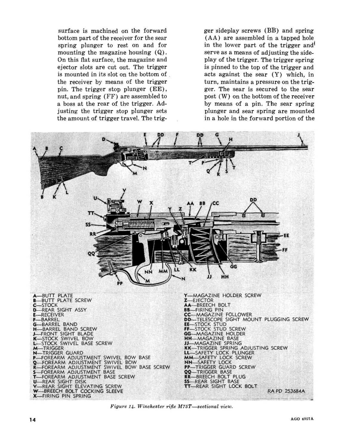
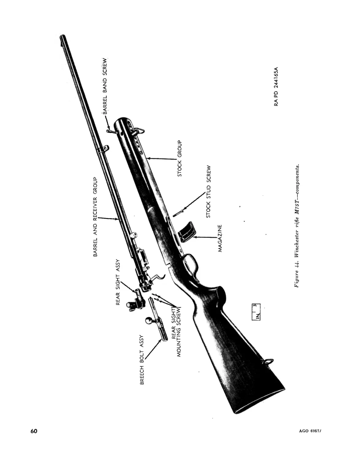
d. Winchester Rifle M75T (fig. 14). The Win-
chester rifle M75T (figs. 3 and 44) consists
basically of the breech bolt assembly, the maga-
zine, rear sight assembly, barrel and receiver
group, and the stock group.
Note. The' key letters shown below in parentheses
refer to figure 14.
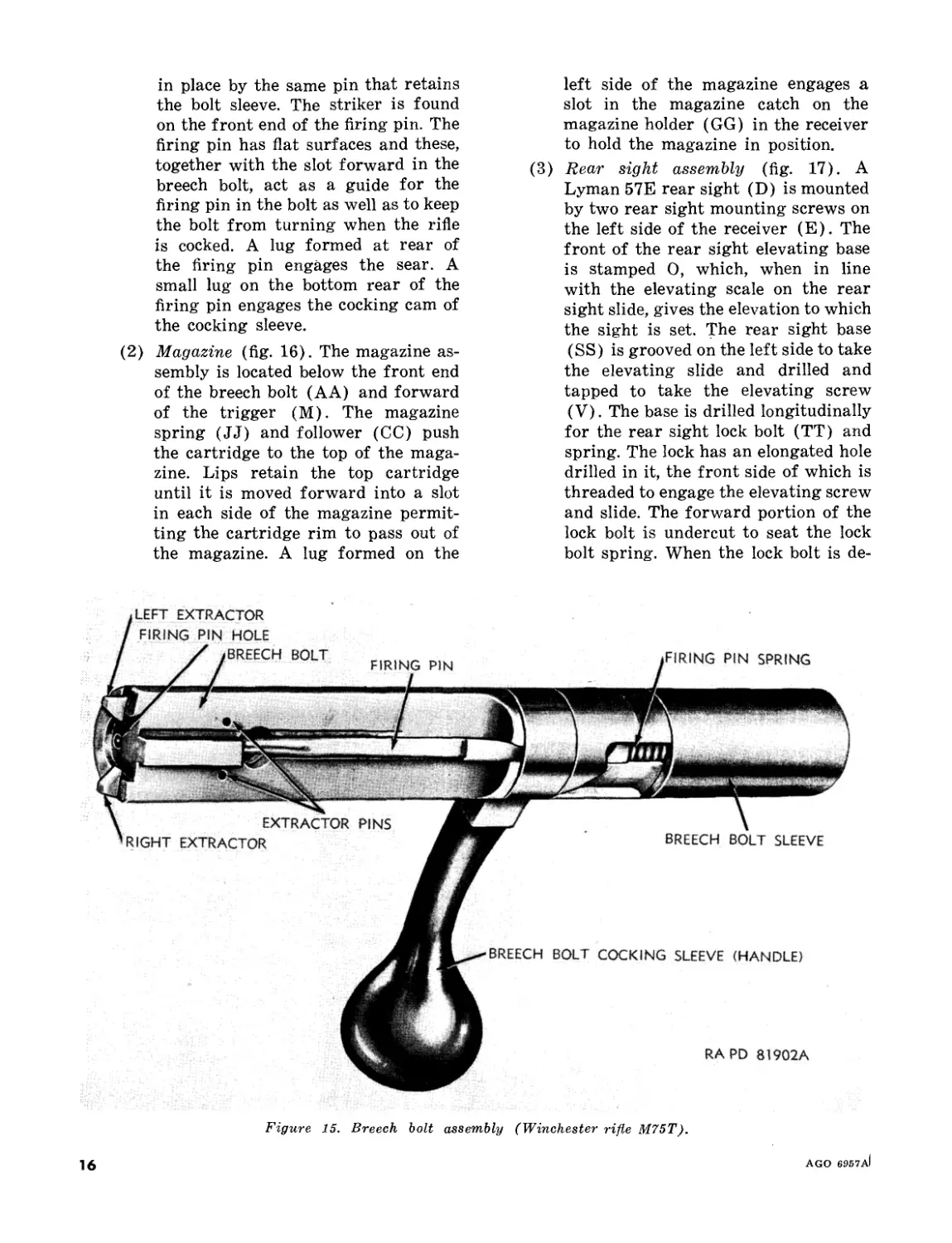
(1) Breech bolt assembly (fig. 15). The
extractors are mounted in two slots
provided in the head of the breech bolt
(AA) and are retained in place by
two extractor pins. A spring is
mounted in a hole at the back end of
each extractor. The forward portion
of the bottom of the breech bolt has
magazine and ejector clearance slots
so that the bolt can slide over the
magazine and the ejector. The lug in
the center of this section serves to
remove the cartridge from the maga-
zine. The front face of the bolt is
chambered to receive the cartridge
rim and has the firing pinhole through
which the striker end of the firing pin
(BB) passes to strike the cartridge.
The back end of the bolt is undercut
to receive the breech bolt sleeve and
the breech bolt cocking sleeve (W).
A hole in the forward part of the
undercut receives the firing pin stop
pin. A hole in the rear receives the
breech bolt sleeve pin. The breech bolt
is bored out to receive the striker end
of the firing pin. A slot cut in the cen-
ter at the bottom of the bolt acts as a
guideway for the bored hole in the
front. The back of the handle of the
bolt cocking sleeve acts against a cam
surface in the receiver to force the
bolt forward when the handle is
lowered. The breech bolt cocking
sleeve has a slot and a cam forward
on its under side. When the handle of
the cocking sleeve is raised, the cam
acts against the cocking projection at
the bottom of the firing pin and forces
the pin rearward against the pressure
of the firing pin spring (X) until the
firing pin notch is in the cocked posi-
tion. A clearance notch for the safety
lever is formed in the rear of the
sleeve just above the cocking cam.
The breech bolt sleeve’ fits over the
rear end of the breech bolt and is re-
tained to it by the breech bolt sleeve
pin. It acts as an inclosure for the fir-
ing pin spring. The breech bolt plug
(RR) is assembled in the rear end of
the sleeve and acts as the rear stop
for the firing pin spring. It is retained
AGO 6957A
15
in place by the same pin that retains
the bolt sleeve. The striker is found
on the front end of the firing pin. The
firing pin has flat surfaces and these,
together with the slot forward in the
breech bolt, act as a guide for the
firing pin in the bolt as well as to keep
the bolt from turning when the rifle
is cocked. A lug formed at rear of
the firing pin engages the sear. A
small lug on the bottom rear of the
firing pin engages the cocking cam of
the cocking sleeve.
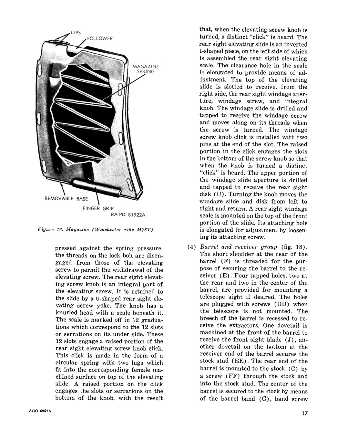
(2) Magazine (fig. 16). The magazine as-
sembly is located below the front end
of the breech bolt (AA) and forward
of the trigger (M). The magazine
spring (JJ) and follower (CC) push
the cartridge to the top of the maga-
zine. Lips retain the top cartridge
until it is moved forward into a slot
in each side of the magazine permit-
ting the cartridge rim to pass out of
the magazine. A lug formed on the
left side of the magazine engages a
slot in the magazine catch on the
magazine holder (GG) in the receiver
to hold the magazine in position.
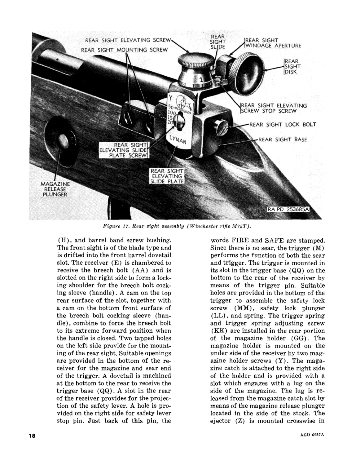
(3) Rear sight assembly (fig. 17). A
Lyman 57E rear sight (D) is mounted
by two rear sight mounting screws on
the left side of the receiver (E). The
front of the rear sight elevating base
is stamped 0, which, when in line
with the elevating scale on the rear
sight slide, gives the elevation to which
the sight is set. The rear sight base
(SS) is grooved on the left side to take
the elevating slide and drilled and
tapped to take the elevating screw
(V). The base is drilled longitudinally
for the rear sight lock bolt (TT) and
spring. The lock has an elongated hole
drilled in it, the front side of which is
threaded to engage the elevating screw
and slide. The forward portion of the
lock bolt is undercut to seat the lock
bolt spring. When the lock bolt is de-
Figure 15. Breech bolt assembly (Winchester rifle M75T).
16
AGO 6957aI
FINGER GRIP
RAPD 81922A
Figure 16. Magazine (Winchester rifle M75T).
pressed against the spring pressure,
the threads on the lock bolt are disen-
gaged from those of the elevating
screw to permit the withdrawal of the
elevating screw. The rear sight elevat-
ing screw knob is an integral part of
the elevating screw. It is retained to
the slide by a U-shaped rear sight ele-
vating screw yoke. The knob has a
knurled head with a scale beneath it.
The scale is marked off in 12 gradua-
tions which correspond to the 12 slots
or serrations on its under side. These
12 slots engage a raised portion of the
rear sight elevating screw knob click.
This click is made in the form of a
circular spring with two lugs which
fit into the corresponding female ma-
chined surface on top of the elevating
slide. A raised portion on the click
engages the slots or serrations on the
bottom of the knob, with the result
that, when the elevating screw knob is
turned, a distinct “click” is heard. The
rear sight elevating slide is an inverted
L-shaped piece, on the left side of which
is assembled the rear sight elevating
scale. The clearance hole in the scale
is elongated to provide means of ad-
justment. The top of the elevating
slide is slotted to receive, from the
right side, the rear sight windage aper-
ture, windage screw, and integral
knob. The windage slide is drilled and
tapped to receive the windage screw
and moves along on its threads when
the screw is turned. The windage
screw knob click is installed with two
pins at the end of the slot. The raised
portion in the click engages the slots
in the bottom of the screw knob so that
when the knob is turned a distinct
“click” is heard. The upper portion of
the windage slide aperture is drilled
and tapped to receive the rear sight
disk (U). Turning the knob moves the
windage slide and disk from left to
right and return. A rear sight windage
scale is mounted on the top of the front
portion of the slide. Its attaching hole
is elongated for adjustment by loosen-
ing its attaching screw.
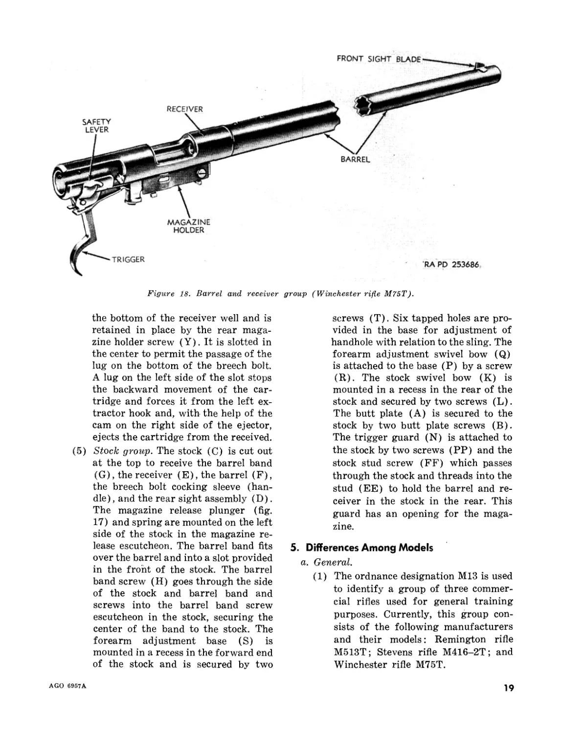
(4) Barrel and receiver group (fig. 18).
The short shoulder at the rear of the
barrel (F) is threaded for the pur-
pose of securing the barrel to the re-
ceiver (E). Four tapped holes, two at
the rear and two in the center of the
barrel, are provided for mounting a
telescope sight if desired. The holes
are plugged with screws (DD) when
the telescope is not mounted. The
breech of the barrel is recessed to re-
ceive the extractors. One dovetail is
machined at the front of the barrel to
receive the front sight blade (J), an-
other dovetail on the bottom at the
receiver end of the barrel secures the
stock stud (EE). The rear end of the
barrel is mounted to the stock (C) by
a screw (FF) through the stock and
into the stock stud. The center of the
barrel is secured to the stock by means
of the barrel band (G), band screw
17
AGO 6957A
REAR SIGHT ELEVATING SCREW'
REAR SIGHT MOUNTING SCREW
RA PD 253685A
MAGAZINE
RELEASE
PLUNGER
REAR
SIGHT
SLIDE
REAR
SIGHT
DISK
REAR SIGHT
ELEVATING SLIDE
PLATE SCREW
REAR SIGHTS.,
ELEVATING fe.
SLIDE PLATE
IREAR SIGHT
|WINDAGE APERTURE
REAR SIGHT LOCK BOLT
ic-REAR SIGHT BASE
IREAR SIGHT ELEVATING
ISCREW STOP SCREW
Figure 17. Rear sight assembly (Winchester rifle M75T).
(H), and barrel band screw bushing.
The front sight is of the blade type and
is drifted into the front barrel dovetail
slot. The receiver (E) is chambered to
receive the breech bolt (AA) and is
slotted on the right side to form a lock-
ing shoulder for the breech bolt cock-
ing sleeve (handle). A cam on the top
rear surface of the slot, together with
a cam on the bottom front surface of
the breech bolt cocking sleeve (han-
dle), combine to force the breech bolt
to its extreme forward position when
the handle is closed. Two tapped holes
on the left side provide for the mount-
ing of the rear sight. Suitable openings
are provided in the bottom of the re-
ceiver for the magazine and sear end
of the trigger. A dovetail is machined
at the bottom to the rear to receive the
trigger base (QQ). A slot in the rear
of the receiver provides for the projec-
tion of the safety lever. A hole is pro-
vided on the right side for safety lever
stop pin. Just back of this pin, the
words FIRE and SAFE are stamped.
Since there is no sear, the trigger (M)
performs the function of both the sear
and trigger. The trigger is mounted in
its slot in the trigger base (QQ) on the
bottom to the rear of the receiver by
means of the trigger pin. Suitable
holes are provided in the bottom of the
trigger to assemble the safety lock
screw (MM), safety lock plunger
(LL), and spring. The trigger spring
and trigger spring adjusting screw
(KK) are installed in the rear portion
of the magazine holder (GG). The
magazine holder is mounted on the
under side of the receiver by two mag-
azine holder screws (Y). The maga-
zine catch is attached to the right side
of the holder and is provided with a
slot which engages with a lug on the
side of the magazine. The lug is re-
leased from the magazine catch slot by
means of the magazine release plunger
located in the side of the stock. The
ejector (Z) is mounted crosswise in
18
AGO 6957A
FRONT SIGHT BLADE
Figure 18. Barrel and receiver
group (Winchester rifle M75T).
the bottom of the receiver well and is
retained in place by the rear maga-
zine holder screw (Y). It is slotted in
the center to permit the passage of the
lug on the bottom of the breech bolt.
A lug on the left side of the slot stops
the backward movement of the car-
tridge and forces it from the left ex-
tractor hook and, with the help of the
cam on the right side of the ejector,
ejects the cartridge from the received.
(5) Stock group. The stock (C) is cut out
at the top to receive the barrel band
(G), the receiver (E), the barrel (F),
the breech bolt cocking sleeve (han-
dle) , and the rear sight assembly (D).
The magazine release plunger (fig.
17) and spring are mounted on the left
side of the stock in the magazine re-
lease escutcheon. The barrel band fits
over the barrel and into a slot provided
in the front of the stock. The barrel
band screw (H) goes through the side
of the stock and barrel band and
screws into the barrel band screw
escutcheon in the stock, securing the
center of the band to the stock. The
forearm adjustment base (S) is
mounted in a recess in the forward end
of the stock and is secured by two
screws (T). Six tapped holes are pro-
vided in the base for adjustment of
handhole with relation to the sling. The
forearm adjustment swivel bow (Q)
is attached to the base (P) by a screw
(R). The stock swivel bow (K) is
mounted in a recess in the rear of the
stock and secured by two screws (L).
The butt plate (A) is secured to the
stock by two butt plate screws (B).
The trigger guard (N) is attached to
the stock by two screws (PP) and the
stock stud screw (FF) which passes
through the stock and threads into the
stud (EE) to hold the barrel and re-
ceiver in the stock in the rear. This
guard has an opening for the maga-
zine.
5. Differences Among Models
a. General.
(1) The ordnance designation M13 is used
to identify a group of three commer-
cial rifles used for general training
purposes. Currently, this group con-
sists of the following manufacturers
and their models: Remington rifle
M513T; Stevens rifle M416-2T; and
Winchester rifle M75T.
AGO 6957A
19
(2) Physical characteristics are different
and are specifically covered in para-
graph 7.
(3) Differences in construction show up as
differences in the operation of various
controls (e.g., safety, rear sight knobs,
magazine release, etc.), internal func-
tioning, and assembly and disassembly
procedures. The differences in opera-
tion are covered for each rifle in para-
graphs 13, 21, and 29. Differences in
internal functioning are covered in
paragraphs 19, 27, and 35. Disassem-
bly and assembly differences are cov-
ered in paragraphs 56 through 67.
(4) Performance characteristics (e.g.,
range, pressure, and muzzle velocity)
are identical.
b. Modification Work Orders.
(1) MWO ORD B25-W1, March 1949,
calls for increasing the depth of the
counterbore on the bolt forward face
of the cal. .22 Remington rifle M513T
to insure proper clearance between
the cartridge seat in the face of the
bolt and the barrel breech when the
bolt is closed.
(2) MWO ORD B25-W2, April 1953,1
calls for cutting approximately Ц
inch from the top of the wooden stock
of the Remington rifle M513T with a
wood rasp to enable the rifleman to
sight the rifle with a greater degree of
comfort.
6. Identification Information
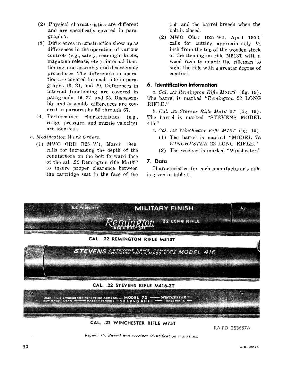
a. Cal. .22 Remington Rifle M513T (fig. 19).
The barrel is marked “Remington 22 LONG
RIFLE.”
b. Cal. .22 Stevens Rifle МЛ16-2Т (fig. 19).
The barrel is marked “STEVENS MODEL
416.”
c. Cal. .22 Winchester Rifle M75T (fig. 19).
(1) The barrel is marked “MODEL 75
WINCHESTER 22 LONG RIFLE.”
(2) The receiver is marked “Winchester.”
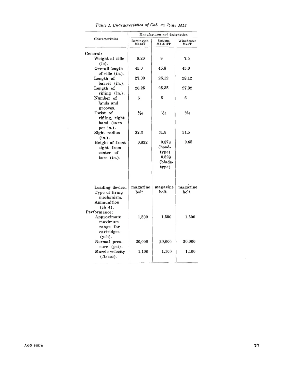
7. Data
Characteristics for each manufacturer’s rifle
is given in table I.
CAL. .22 STEVENS RIFLE M416-2T
CAL. .22 WINCHESTER RIFLE M75T
RA PD 253687A
Figure 19. Barrel and receiver identification markings.
20
AGO «957 A
Table I. Characteristics of Cal. .22 Rifle M13
Manufacturer and designation
Characteristics Remington M513T Stevens M416-2T Winchester M75T
General:
Weight of rifle 8.20 9 7.5
(lb). Overall length 45.0 45.8 45.0
of rifle (in.). Length of 27.00 26.12 28.12
barrel (in.). Length of 26.25 25.35 27.32
rifling (in.). Number of 6 6 6
lands and
grooves. Twist of Vie Vie Vie
rifling, right hand (turn per in.).
Sight radius 32.3 31.8 31.5
(in.). Height of front 0.832 0.878 0.65
sight from (hood-
center of type)
bore (in.). 0.828 (blade- type)
Loading device- magazine magazine magazine
Type of firing mechanism. Ammunition bolt bolt bolt
(ch 4).
Performance:
Approximate 1,500 1,500 1,500
maximum range for cartridges (yds).
Normal pres- 20,000 ,20,000 20,000
sure (psi). Muzzle velocity 1,100 1,100 1,100
(ft/sec).
AGO 6957A
21
CHAPTER 2
OPERATING INSTRUCTIONS
Section I. SERVICE UPON RECEIPT OF MATERIEL
8. General
a. When a new or reconditioned rifle is re-
ceived by the using organization, it is the re-
sponsibility of the officer in charge to determine
whether the materiel has been properly pre-
pared for service by the supplying organization
and to be sure it is in condition to perform any
mission to which it may be assigned when
placed in service. For this purpose, inspect all
assemblies, subassemblies, and accessories to be
sure they are properly assembled, secure, clean,
and correctly adjusted and/or lubricated. Check
all tools and equipment against ORD 7 SNL
B-25 to be sure every item is present and de-
termine that they are in good condition, clean,
and properly mounted or stowed.
b. Make a list of any missing parts and of
any malfunctions. Correct any deficiencies as
soon as possible.
c. Pay special attention to small parts, as they
are more likely to become lost and may seriously
affect the proper functioning of the rifle.
9. New Materiel
a. New rifles received from storage are packed
in heat-sealed, water-vaporproof bags, and cot-
ton stockinette (Saran packing).
b. Rifles packed using these methods are com-
pletely coated with a light film of special pre-
servative oil and are serviced as follows:
(1) Remove rifle and packing from crate.
(2) Remove protective covering from rifle.
(3) To insure that there is no corrosion
present, missing parts, or incorrect
assembly, proceed as described in par-
agraph 8.
c. Clean oil film from all parts. Check front
face of the bolt and other adjacent surfaces
subject to powder fouling and corrosion.
Note. All new rifles are function-fired and therefore
certain parts will have their protective finish worn
away. This is a normal condition and is not to be con-
strued as excessive wear.
d. Clean bore (par. 49), using cleaning rod
Ml 5503837 and patches.
e. Check rifle to be sure that all modification
work orders have been applied (par. 5b).
f. Lubricate (pars. 44-47) and assemble rifle.
10. Used Materiel
Used materiel requires the same inspection
and service prescribed for new materiel (par.
9). In addition, check all components for signs
of excessive wear and corrosion. Check for miss-
ing parts and correct any deficiencies.
11. Disassembly of Rifle Prior to Cleaning
Refer to paragraphs 56 through 67, for dis-
assembly of the following groups or assemblies:
a. The bolt assembly, bolt group, or breech
bolt assembly.
b. The magazine assembly or magazine.
c. The rear sight assembly or the receiver
extension rear sight assembly.
d. The barrel and receiver group.
Note. During any disassembly, mark parts, assem-
blies, and/or groups to facilitate assembly of items in
their respective rifles. Interchange of parts between
rifles during assembly could damage the rifle and/or
render the rifles unsafe or inaccurate.
Section II. OPERATION UNDER USUAL CONDITIONS FOR REMINGTON RIFLE M513T
12. General and contains the instructions for the mechani-
This section describes and illustrates the op- cal steps necessary to operate these controls
eration and location of the controls (par. 13) (pars. 14-18) and explains the functioning
22
AGO 6957A
(par. 19) of the Remington rifle M513T.
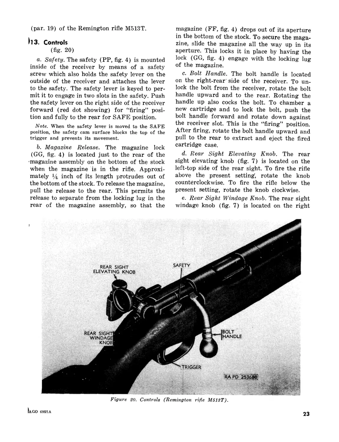
113. Controls
(fig. 20)
a. Safety. The safety (PP, fig. 4) is mounted
inside of the receiver by means of a safety
screw which also holds the safety lever on the
outside of the receiver and attaches the lever
to the safety. The safety lever is keyed to per-
mit it to engage in two slots in the safety. Push
the safety lever on the right side of the receiver
forward (red dot showing) for “firing” posi-
tion and fully to the rear for SAFE position.
Note. When the safety lever is moved to the SAFE
position, the safety cam surface blocks the top of the
trigger and prevents its movement.
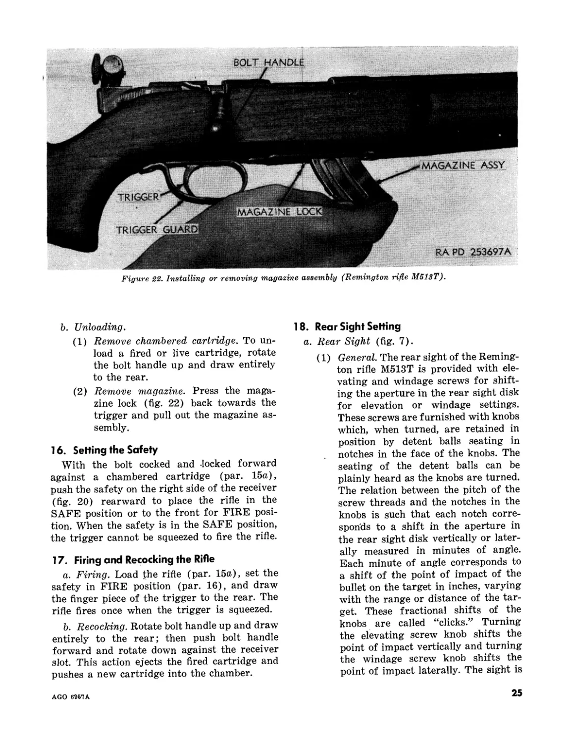
b. Magazine Release. The magazine lock
(GG, fig. 4) is located just to the rear of the
magazine assembly on the bottom of the stock
when the magazine is in the rifle. Approxi-
mately Ц inch of its length protrudes out of
the bottom of the stock. To release the magazine,
pull the release to the rear. This permits the
release to separate from the locking lug in the
rear of the magazine assembly, so that the
magazine (FF, fig. 4) drops out of its aperture
in the bottom of the stock. To secure the maga-
zine, slide the magazine all the way up in its
aperture. This locks it in place by having the
lock (GG, fig. 4) engage with the locking lug
of the magazine.
c. Bolt Handle. The bolt handle is located
on the right-rear' side of the receiver. To un-
lock the bolt from the receiver, rotate the bolt
handle upward and to the rear. Rotating the
handle up also cocks the bolt. To chamber a
new cartridge and to lock the bolt, push the
bolt handle forward and rotate down against
the receiver slot. This is the “firing” position.
After firing, rotate the bolt handle upward and
pull to the rear to extract and eject the fired
cartridge case.
d. Rear Sight Elevating Knob. The rear
sight elevating knob (fig. 7) is located on the
left-top side of the rear sight. To fire the rifle
above the present setting, rotate the knob
counterclockwise. To fire the rifle below the
present setting, rotate the knob clockwise.
e. Rear Sight Windage Knob. The rear sight
windage knob (fig. 7) is located on the right
Figure 20. Controls (Remington rifle M513T).
Iago 695ia
23
side of the rear sight. To fire the rifle to the
right of the present setting, rotate the knob
counterclockwise. To fire the rifle to the left
of the present setting, rotate the knob clockwise.
f. Trigger. The trigger (L, fig. 4) is located
in the bottom of the stock immediately below
the bolt handle. To fire the rifle, squeeze trigger
to the rear against the tension of the trigger
spring (MM, fig. 4). The squeezing of the trig-
ger releases the firing pin (Y, fig. 4), to permit
the offset striker end of , the pin to strike the
cartridge rim.
14. Loading the Magazine
The magazine has a capacity of six car-
tridges. The magazine is loaded by depressing
the magazine follower and inserting one car-
tridge at a time. With its rim toward the back,
press the cartridge down and into the slots on
each side of the top of the magazine and back
under the lips of the magazine (fig. 21).
Note. As each succeeding cartridge is inserted, it
pushes the first one toward the bottom of the magazine.
15. Loading and Unloading the Rifle
a. Loading.
(1) Insert magazine. Insert loaded maga-
zine (par. 14) through the magazine
opening at the bottom of the receiver
just forward of the trigger guard
(fig. 22) and push upward until locked
in place. If an extra cartridge is to be
used, proceed as in (2) below. If an
extra cartridge will not be used, rotate
bolt handle up and draw entirely to
rear; then push bolt handle forward
and rotate down against the receiver
slot. This action cocks the rifle and
pushes the top cartridge from the
magazine into the chamber.
(2) Insert extra cartridge. An extra car-
tridge, making a total of seven, can be
used. To insert extra cartridge, open
the bolt, place a cartridge fully in the
chamber by hand and close the bolt
before inserting the loaded magazine
((1) above).
Figure 21. Loading cartridge into magazine assembly (Remington rifle M513T).
24
AGO 6957A
Figure 22. Installing or removing magazine assembly (Remington rifle M51ST).
b. Unloading.
(1) Remove chambered cartridge. To un-
load a fired or live cartridge, rotate
the bolt handle up and draw entirely
to the rear.
(2) Remove magazine. Press the maga-
zine lock (fig. 22) back towards the
trigger and pull out the magazine as-
sembly.
16. Setting the Safety
With the bolt cocked and locked forward
against a chambered cartridge (par. 15a),
push the safety on the right side of the receiver
(fig. 20) rearward to place the rifle in the
SAFE position or to the front for FIRE posi-
tion. When the safety is in the SAFE position,
the trigger cannot be squeezed to fire the rifle.
17. Firing and Recocking the Rifle
a. Firing. Load the rifle (par. 15a), set the
safety in FIRE position (par. 16), and draw
the finger piece of the trigger to the rear. The
rifle fires once when the trigger is squeezed.
b. Recocking. Rotate bolt handle up and draw
entirely to the rear; then push bolt handle
forward and rotate down against the receiver
slot. This action ejects the fired cartridge and
pushes a new cartridge into the chamber.
1 8. Rear Sight Setting
a. Rear Sight (fig. 7).
(1) General. The rear sight of the Reming-
ton rifle M513T is provided with ele-
vating and windage screws for shift-
ing the aperture in the rear sight disk
for elevation or windage settings.
These screws are furnished with knobs
which, when turned, are retained in
position by detent balls seating in
notches in the face of the knobs. The
seating of the detent balls can be
plainly heard as the knobs are turned.
The relation between the pitch of the
screw threads and the notches in the
knobs is such that each notch corre-
sponds to a shift in the aperture in
the rear sight disk vertically or later-
ally measured in minutes of angle.
Each minute of angle corresponds to
a shift of the point of impact of the
bullet on the target in inches, varying
with the range or distance of the tar-
get. These fractional shifts of the
knobs are called “clicks.” Turning
the elevating screw knob shifts the
point of impact vertically and turning
the windage screw knob shifts the
point of impact laterally. The sight is
AGO 6957A
25
usually adjusted at the factory, but
to make sure it is correct, it should
be checked on the range.
(2) Redfield 75RT rear sight. This rifle
is furnished with the Redfield 75RT
rear sight, with 14-minute “clicks.”
Each “click” corresponds to a Ц-
minute change in angle of sight; such
a change corresponds to a Vi-inch
shift of the point of impact of the bul-
let on the target at 100 yards. This
shift varies with the distance; as the
range is doubled or halved, the amount
of shift of the point of impact is
doubled or halved. The point of impact
will be shifted % 6 inch at 25 yards,
i/s inch at 50 yards, Vi inch at 100
yards, and V2 inch at 200 yards, etc.
The windage slide moves laterally in
the elevating slide. The elevating slide
is graduated and marked in minutes
of angle. Each division represents 3
minutes, and every 5 divisions are
marked to represent 15, 30, 45, and
60 minutes of angle, respectively. The
right side of the slide is blank and
can be marked for ranges in yards
when determined. The elevating knob
has 12 click divisions, each of which
corresponds to a change of 14 minute
of angle. Thus, a full revolution of this
knob corresponds to 3 minutes of angle
or 1 division on the slide. The windage
index plate likewise is divided into 3-
minute divisions with a 0 stamped
at the central point. The windage knob
corresponds in divisions and clicks to
the elevating knob. The windage index
plate and elevating (slide) plate are
adjustable for setting when the zero
of the rifle is determined.
Note. One “click” of the elevating or wind-
age knob represents a shift of Ук; inch at
25 yards.
b. Zeroing the Rear Sight.
(1) The rear sight of the rifle should be
checked to ascertain the basic or
“zero” setting. For accuracy, zero
setting is best performed at short
range. When zero setting is deter-
mined and noted, the rifle shoud be
checked at various yardages and any
variations from computed settings
noted. In sighting-in this rifle, a large
target should be used with a cross in'
its center and the rifle fired from a
rest. Such a target will register the
first few shots which may be out-of-
line and clearly indicate the point of
impact vertically or laterally from
center. All sighting-in should be done
on a safe range and on a day without
any wind. As short ranges are pref-
erable for such zero settings, 25
yards are taken, which means 25 yards
from the muzzle of the rifle to the
target. As the point of impact of each
bullet will vary somewhat, the center
of the group should be considered.
(2) To set the sight for minimum range
and zero windage, take a position 25
yards from the target and proceed as
described in (a) through (d) below.
(a) Screw the elevating slide down as
far as it will go by turning the ele-
vating screw knob (fig. 7). Loosen
the two elevating plate screws and
adjust the elevating slide plate
pointer to aline with 0 marking
on the slide for a test shot. Tighter
the two screws.
(b) Set the windage yoke as near the
center (bore line) as possible by
turning the windage screw knob
(fig. 7).
(c) Fire five shots and correct for wind-
age to center the point of bullet
impact laterally by turning the
windage knob (par. 13e) in the
proper direction. Moving the wind-
age yoke to the right will shift the
point of bullet impact on the target
to the right and vice versa. When
the point of bullet impact is cen-
tered laterally, set the windage in-
dex plate so that the 0 alines with
the indicating line on the yoke.
(d) Correct for elevation in like manner
to center the point of bullet impact
vertically by turning the elevating
knob (par. 13d) in the proper direc-
tion. Moving the elevating slide up
raises the point of bullet impact on
26
AGO 6967A
the target and vice versa. When
point of bullet impact is centered
vertically, loosen the two elevating
plate screws and reset the pointer
of the elevating slide plate at 0 and
mark 25 on the slide opposite 0 to
indicate yardage.
19. Functioning
Note. The key letters shown below in parentheses
refer to figure 4.
a. When the bolt handle is raised to the un-
locked position, this portion of the handle ro-
tates around the bolt (E), which is prevented
from turning by the engagement of the ejector
(Z) with the grooved bottom of the bolt. The
firing pin retaining pin extending through the
rear of the firing pin (Y) and through slots in
the bolt walls engages the cam surface in the
handle sleeve. The rotation of this cam, when
the handle is raised, forces the firing pin to the
rear against the plunger and indicator, com-
pressing the mainspring (QQ) and positioning
the firing pin in firing position. When the firing
pin has reached its cocked position, the sear
notch is directly over the sear (W), which then
rises under the indirect action of the trigger
spring (MM) and enters the notch. The trigger
(L), being pivoted on the sear, returns to firing
position at the same time.
b. As the bolt (E) is retracted, the cartridge
case, held against the bolthead by the two ex-
tractors, is extracted from the chamber. Just
before the bolt is fully retracted, the cartridge
case strikes the ejector (Z), and as the bolt is
further retracted, the cartridge rim is forced
Se ction 111. OPERATIONS UNDER USUAL
20. General
This section describes and illustrates the op-
eration and location of the controls (par. 21)
and contains the instructions for the mechanical
steps necessary to operate these controls (pars.
22-26) and explains the functioning (par. 27)
of the Stevens rifle M416-2T.
21. Controls
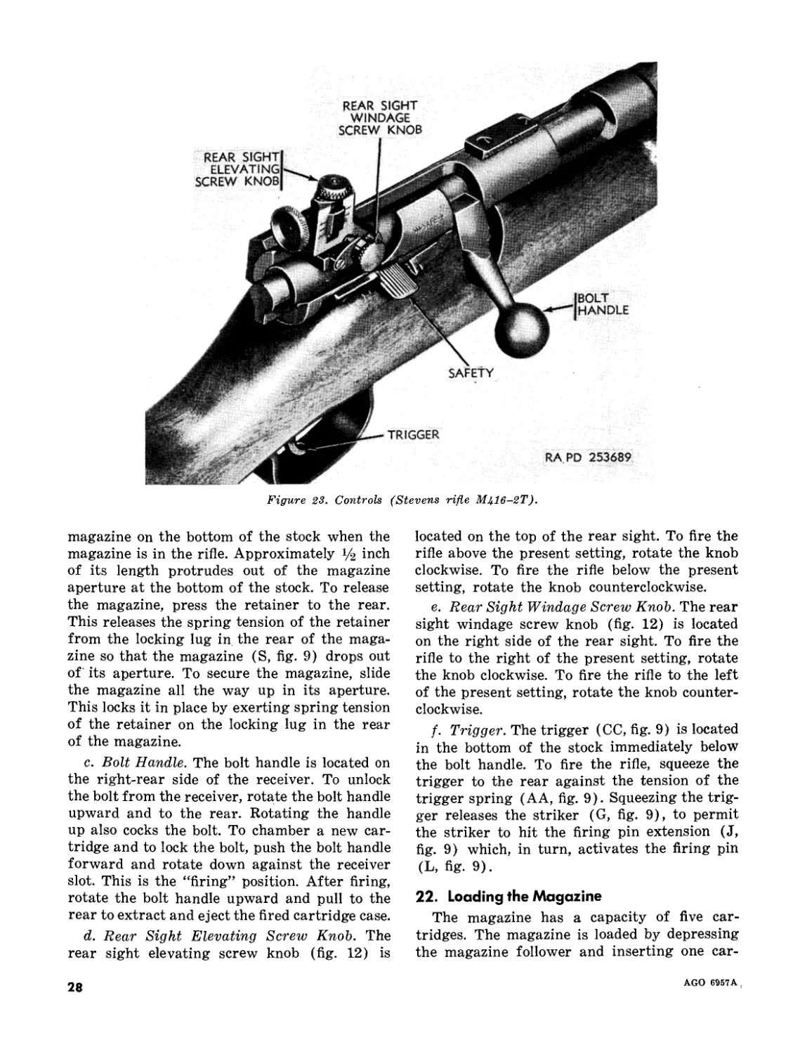
(fig. 23)
a. Safety. The safety and safety spring are
mounted on the side of the receiver by means
of two screws. The screw holes in the safety
are elongated, permitting it to move to the front
out from the sloping claw of the left extractor,
is pivoted to the right around the right extrac-
tor hook, and thrown out of the receiver upward
and to the right. The engagement of the sear
projection anchored in the receiver with the
magazine clearance grooves prevents full with-
drawal of the bolt from the receiver (F) until
the trigger is squeezed to pivot the sear down
and away from the bolt.
c. As the bolt uncovers the magazine (FF)
during retraction, the magazine spring (EE)
and follower (BB) partially raise a cartridge
out of the magazine, where the rim is retained
between the aperture formed by the two walls
of the magazine so that the cartridge is held
in an inclined position with its front end ex-
tending up and out of the magazine. When the
bolt is pushed forward, the lug on the bottom
of the bolthead pushes the cartridge forward
until the rim is released from the magazine
aperture and forced up under pressure of the
magazine spring (EE) into the recess of the
bolthead face and under the extractors. Further
closing of the bolt seats the cartridge in the
barrel chamber (G). Turning the bolt handle
down locks the bolt, leaving the firing pin held
by the sear notch in position for firing.
d. When the trigger (L) is squeezed to the
rear, it pivots on its mounting pin. This trigger
movement causes the sear (W), which pivots
on the sear stud, to be disengaged from the
sear notch in the firing pin (Y). When the
firing pin is disengaged; the compressed main-
spring (QQ) forces the firing pin forward to
strike the cartridge rim.
CONDITIONS FOR STEVENS RIFLE M416-2T
or rear. When moved forward, the lug on the
safety spring seats into one of the grooves in
the safety and retains the safety in the SAFE
position. When moved rearward, the lug on the
safety spring seats in the other groove in the
safety and retains the safety in the ready posi-
tion. Push the safety rearward for “firing”
position and fully to the front for SAFE posi-
tion.
Note. When the safety is moved to the SAFE posi-
tion, the safety locking lug moves forward into engage-
ment with the trigger and prevents its movement.
b. Magazine Retainer. The magazine retainer
(U, fig. 9) is located just to the rear of the
AGO 69Б7А
27
Figure 23. Controls (Stevens rifle M4I6-2T).
magazine on the bottom of the stock when the
magazine is in the rifle. Approximately 1/2 inch
of its length protrudes out of the magazine
aperture at the bottom of the stock. To release
the magazine, press the retainer to the rear.
This releases the spring tension of the retainer
from the locking lug in the rear of the maga-
zine so that the magazine (S, fig. 9) drops out
of its aperture. To secure the magazine, slide
the magazine all the way up in its aperture.
This locks it in place by exerting spring tension
of the retainer on the locking lug in the rear
of the magazine.
c. Bolt Handle. The bolt handle is located on
the right-rear side of the receiver. To unlock
the bolt from the receiver, rotate the bolt handle
upward and to the rear. Rotating the handle
up also cocks the bolt. To chamber a new car-
tridge and to lock the bolt, push the bolt handle
forward and rotate down against the receiver
slot. This is the “firing” position. After firing,
rotate the bolt handle upward and pull to the
rear to extract and eject the fired cartridge case.
d. Rear Sight Elevating Screw Knob. The
rear sight elevating screw knob (fig. 12) is
located on the top of the rear sight. To fire the
rifle above the present setting, rotate the knob
clockwise. To fire the rifle below the present
setting, rotate the knob counterclockwise.
e. Rear Sight Windage Screw Knob. The rear
sight windage screw knob (fig. 12) is located
on the right side of the rear sight. To fire the
rifle to the right of the present setting, rotate
the knob clockwise. To fire the rifle to the left
of the present setting, rotate the knob counter-
clockwise.
Trigger. The trigger (CC, fig. 9) is located
in the bottom of the stock immediately below
the bolt handle. To fire the rifle, squeeze the
trigger to the rear against the tension of the
trigger spring (AA, fig. 9). Squeezing the trig-
ger releases the striker (G, fig. 9), to permit
the striker to hit the firing pin extension (J,
fig. 9) which, in turn, activates the firing pin
(L, fig. 9).
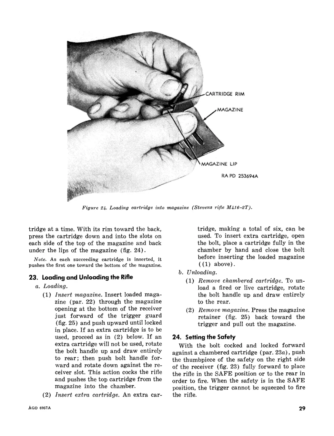
22. Loading the Magazine
The magazine has a capacity of five car-
tridges. The magazine is loaded by depressing
the magazine follower and inserting one car-
28
AGO 6957A ,
Figure 24. Loading cartridge into magazine (Stevens rifle M416-2T).
tridge at a time. With its rim toward the back,
press the cartridge down and into the slots on
each side of the top of the magazine and back
under the lips of the magazine (fig. 24).
Note. As each succeeding cartridge is inserted, it
pushes the first one toward the bottom of the magazine.
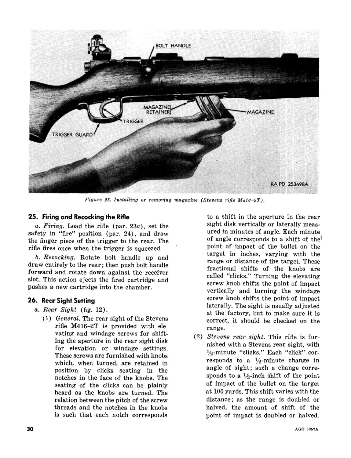
23. Loading and Unloading the Rifle
a. Loading.
(1) Insert magazine. Insert loaded maga-
zine (par. 22) through the magazine
opening at the bottom of the receiver
just forward of the trigger guard
(fig. 25) and push upward until locked
in place. If an extra cartridge is to be
used, proceed as in (2) below. If an
extra cartridge will not be used, rotate
the bolt handle up and draw entirely
to rear; then push bolt handle for-
ward and rotate down against the re-
ceiver slot. This action cocks the rifle
and pushes the top cartridge from the
magazine into the chamber.
(2) Insert extra cartridge. An extra car-
tridge, making a total of six, can be
used. To insert extra cartridge, open
the bolt, place a cartridge fully in the
chamber by hand and close the bolt
before inserting the loaded magazine
((1) above).
b. Unloading.
(1) Remove chambered cartridge. To un-
load a fired or live cartridge, rotate
the bolt handle up and draw entirely
to the rear.
(2) Remove magazine. Press the magazine
retainer (fig. 25) back toward the
trigger and pull out the magazine.
24. Setting the Safety
With the bolt cocked and locked forward
against a chambered cartridge (par. 23a), push
the thumbpiece of the safety on the right side
of the receiver (fig. 23) fully forward to place
the rifle in the SAFE position or to the rear in
order to fire. When the safety is in the SAFE
position, the trigger cannot be squeezed to fire
the rifle.
AGO 6957A
29
Figure 25. Installing or removing magazine (Stevens rifle МЫ6-2Т).
25. Firing and Recocking the Rifle
a. Firing. Load the rifle (par. 23a), set the
safety in “fire” position (par. 24), and draw
the finger piece of the trigger to the rear. The
rifle fires once when the trigger is squeezed.
b. Recocking. Rotate bolt handle up and
draw entirely to the rear; then push bolt handle
forward and rotate down against the receiver
slot. This action ejects the fired cartridge and
pushes a new cartridge into the chamber.
26. Rear Sight Setting
a. Rear Sight (fig. 12).
(1) General. The rear sight of the Stevens
rifle M416-2T is provided with ele-
vating and windage screws for shift-
ing the aperture in the rear sight disk
for elevation or windage settings.
These screws are furnished with knobs
which, when turned, are retained in
position by clicks seating in the
notches in the face of the knobs. The
seating of the clicks can be plainly
heard as the knobs are turned. The
relation between the pitch of the screw
threads and the notches in the knobs
is such that each notch corresponds
to a shift in the aperture in the rear
sight disk vertically or laterally meas-
ured in minutes of angle. Each minute
of angle corresponds to a shift of the'
point of impact of the bullet on the
target in inches, varying with the
range or distance of the target. These
fractional shifts of the knobs are
called “clicks.” Turning the elevating
screw knob shifts the point of impact
vertically and turning the windage
screw knob shifts the point of impact
laterally. The sight is usually adjusted
at the factory, but to make sure it is
correct, it should be checked on the
range.
(2) Stevens rear sight. This rifle is fur-
nished with a Stevens rear sight, with
i/ii-minute “clicks.” Each “click” cor-
responds to a i/^-minute change in
angle of sight; such a change corre-
sponds to a ^-inch shift of the point
of impact of the bullet on the target
at 100 yards. This shift varies with the
distance; as the range is doubled or
halved, the amount of shift of the
point of impact is doubled or halved.
30
AGO 6957A
The point of impact will be shifted
Ув inch a't 25 yards, % inch at 50
yards, and Уч inch at 100 yards, etc.
The elevating slide moves laterally in
the windage slide. The windage slide
is marked in 10 divisions, each of
which represents 6 minutes of angle.
There is no alinement mark on the
elevating slide or on the base to aline
the windage slide. Such marks should
be made when the sight has been ad-
justed for minimum range and zero
windage. There are no marks on the
elevating or windage screw knobs.
Each knob is divided into six click
divisions, each division representing
a change of Уч minute of angle. Two
full revolutions of the knobs or 12
clicks represent 6 minutes of angle,
or in the case of the elevating knob,
1 division on the windage slide.
Note. One “click” of the elevating or wind-
age knob represents a shift of % inch at
25 yards.
b. Zeroing the Rear Sight.
(1) The rear sight of the rifle should be
checked to ascertain the basic or
“zero” setting. For accuracy, zero
setting is best performed at short
range. When zero setting is determined
and noted, the rifle should be checked
at various ranges and any variations
from computed settings noted. In
sighting-in this rifle, a large target
should be used with a cross in its cen-
ter and the rifle fired from a rest. Such
a target will register the first few
shots which may be out-of-line and
clearly indicate the point of impact
vertically or laterally from center. All
sighting-in should be done on a safe
range and on a day without any wind.
As short ranges are preferable for
such zero settings, 25 yards are taken,
which means 25 yards from the muzzle
of the rifle to the target. As the point
of impact of each bullet will vary
somewhat, the center of the group
should be considered.
(2) To set the sight for minimum range
and zero windage, take a position 25
yards from the target and proceed as
described in (a) through (d) below.
(a) Screw the elevating slide down as
far as it will go by turning the ele-
vating screw knob (fig. 12). If yard-
age is marked on the scale, the slide
may be set for proper yardage for a
test shot.
(b) Set the windage slide as near the
center (bore line) as possible by
turning the windage screw knob
(fig. 12).
(c) Fire five shots and correct for
windage, to center the point of bullet
impact laterally, by turning the
windage screw knob (par. 21e) in
the proper direction. Moving the
windage slide to the right will shift
the point of bullet impact on the tar-
get to the right and vice versa. When
the point of bullet impact is cen-
tered laterally, mark the windage
slide and sight base to indicate the
center position.
(d) Correct for elevation in like manner,
to center the point of bullet impact
vertically, by moving the elevating
screw knob (par. 21d) in the proper
direction. Moving the elevating slide
up raises the point of bullet impact
on the target and vice versa. When
point of bullet impact is centered
vertically, mark the elevating slide
to correspond with 0 stamped on
the scale on the windage slide.
27. Functioning
Note. The key letters shown below in parentheses
refer to figure 9.
a. Raising the bolt handle rotates the rear
portion of the bolt in the receiver. The bolt-
head (K) is prevented from rotating because
the ejector, which is integral with the magazine
housing (Q), is seated in a slot in the bottom
of the bolt. The striker (G) is now locked
against rotation, because the cocking piece
(GG) and the striker are pinned together and
the cocking piece is held in a slot in the re-
ceiver. As the bolt handle is raised, a cam on
the rear of the bolt body (H) engages the cock-
ing piece, forcing it and the striker to the rear,
compressing the mainspring (F) between the
striker collar and the striker shoulder face. This
GO 6957A
31
retraction of the striker permits the sear (Y)
to engage with the sear notch on the bottom of
the striker under pressure of the sear spring
(V) and plunger. As the back of the sear pivots
upward, it returns the trigger (CC) to the
firing position.
b. As the bolt is retracted, the extractors
holding the cartridge against the bolthead face
(K) pull the case from the firing chamber of
the barrel. Just before the bolt is fully retracted,
the cartridge case strikes the ejector. As the
bolt is further retracted, the cartridge is forced
over the claw of the left extractor, is pivoted to
the right around the hook of the right extractor,
and thrown out of the receiver upward and to
the right. The locking of the rear face of the
sear projection with the rear face of the bolt-
head prevents full withdrawal of the bolt from
the receiver until the trigger (CC) is squeezed
to pivot the sear (Y) away from the bolt.
c. As the bolthead (K) uncovers the maga-
zine (S) during its retraction, the magazine
spring (T) and follower (N) raise a cartridge
partially out of the magazine, where the rim is
retained between the lips formed on the walls
and the cartridge is held- in an inclined position
extending up and out of the magazine. When
the bolt is pushed forward to its closed posi-
tion, the lug on the bottom of the bolthead
pushes the cartridge forward until the rim is
released at the end of the magazine lips and
forced up under pressure of the magazine spring
into the recess in the bolthead face and under
the extractors. As the bolt reaches its foremost
position, the cartridge is seated in the chamber
of the barrel.
d. Putting the bolt handle down in the firing
position, locks the bolt to the receiver and
rotates the cocking cam surface on the bolt
body (H) away from a similar cam cocking
surface on the cocking piece (GG), and the
striker (G) is held in the sear notch in firing
position.
e. When the trigger (CC) is squeezed, it
pivots on its mounting pin and its forward pro-
jection depresses the sear (Y), disengaging
the sear projection on the striker (G). The
compressed mainspring (F) then drives the
firing pin extension (J) which, in turn, drives
the firing pin (L) forward against the rim of
the cartridge.
Section IV. OPERATION UNDER USUAL CONDITIONS FOR WINCHESTER RIFLE M75T.
28. General
This section describes and illustrates the op-
eration and location of the controls (par. 29)
and contains the instructions for the mechani-
cal steps necessary to operate these controls
(pars. 30-34) and explains the functioning
(par. 35) of the Winchester rifle M75T.
29. Controls
(fig. 26)
a. Safety. The safety lock (NN, fig. 14) is
attached to the under side of the trigger (M,
fig. 14) by the safety lock screw (MM, fig. 14).
The safety lock plunger (LL, fig. 14) and spring
are located in a hole in the front of the trigger
and engage a detent in the safety lock. The
safety lever pivots on the trigger pin. This
lever has two extensions at the lower end. One
engages a slot in the safety lock and the other
extends through the receiver wall and prevents
the opening of the bolt when the lever is in
the SAFE position by engaging the safety
lever slot in the breech bolt sleeve (handle).
At the same time, the safety lock is pushed
forward and engages an undercut in the maga-
zine holder to prevent trigger movement. Push
the safety lever on the right side of the re-
ceiver forward for FIRE position (word FIRE
exposed) and fully to the rear for SAFE posi-
tion (word SAFE exposed).
b. Magazine Release Plunger. The magazine
release plunger is located on the left side of the
stock just below the ejection opening in the
receiver. To release the magazine, press maga-
zine release plunger “in.” The magazine release
plunger moves the magazine catch to the right,
thereby disengaging the magazine catch slot
from the locking lug on the right side of the
magazine and permitting the magazine to drop
from its aperture in the stock. To secure the
magazine, slide the magazine all the way up in
its aperture. The spring action of the magazine
catch prevents the magazine from falling out.
c. Breech Bolt Cocking Sleeve (Handle). The
breech bolt cocking sleeve (handle) is located
on the right-rear side of the receiver. To un-
3?
AGO 6957A
BREECH BOLT
RAPD 253690A
Figure 26. Controls (Winchester rifle M75T).
lock the bolt from the receiver, rotate the breech
bolt cocking sleeve (handle) upward and to
the rear. Rotating the sleeve up also cocks the
bolt. To chamber a new cartridge and to lock
the bolt, push the cocking sleeve forward and
rotate down against the receiver slot. This is
the “firing” position. After firing, rotate the
cocking sleeve upward and pull to the rear to
extract and eject the fired cartridge case.
d. Rear Sight Elevating Knob. The rear
sight elevating screw knob is integral with the
elevating screw (fig. 17) and is located on the
left top of the rear sight. To fire the rifle above
the present setting, rotate the knob counter-
clockwise. To fire the rifle below the present
setting, rotate the knob clockwise.
e. Rear Sight Windage Knob. The rear sight
windage screw knob is integral with the wind-
age screw (fig. 17) and is located on the right
side of the rear sight. To fire the rifle to the
right of the present setting, rotate the knob
counterclockwise. To fire the rifle to the left of
the present setting, rotate the knob clockwise.
f. Trigger. The trigger (M, fig. 14) is located
in the bottom of the stock immediately below
the breech bolt cocking sleeve (handle). To fire
the rifle, squeeze trigger to the rear against the
tension of the trigger spring. Squeezing the
trigger releases the firing pin (BB, fig. 14), to
permit the offset end of the pin to strike the
cartridge rim.
30. Loading the Magazine
The magazine has a capacity of five car-
tridges The magazine is loaded by depressing
the magazine follower and inserting one car-
tridge at a time. With its rim toward the back,
press the cartridge down and into the slots on
each side of the top of the magazine and back
under the lips of the magazine (fig. 27).
Note. As each succeeding cartridge is inserted, it
pushes the first one toward the bottom of the magazine.
31. Loading and Unloading the Rifle
a. Loading.
Warning: The bolt cannot be unlocked nor
retracted with the safety (par. 29a) in the
SAFE position. Therefore, the safety should
be placed in the FIRE position when cham-
bering a cartridge.
(1) Insert magazine. Insert loaded maga-
zine (par. 30) through the magazine
opening at the bottom of the receiver
just forward of the trigger guard (fig.
AGO 6957A
33
MAGAZINE
MAGAZINE LIP
RAPD 253695A
magazine (Winchester rifle M75T).
Figure 27. Loading cartridge
into
— CARTRIDGE RIM
28) and push upward until locked in
place. If an extra cartridge is to be
used, proceed as in (2) below. If an
extra cartridge will not be used, ro-
tate breech bolt cocking sleeve (han-
dle) up and draw entirely to the rear;
then push cocking sleeve forward and
rotate down against the receiver slot.
This action cocks the rifle and pushes
the top cartridge from the magazine
into the chamber.
(2) Insert extra magazine. An extra car-
tridge, making a total of six, can be
used. To insert extra cartridge, open
Figure 28. Installing or removing magazine (Winchester rifle M75T).
34
AGO 6957A.
the bolt, place a cartridge fully in the
chamber by hand and close the bolt
before inserting the loaded magazine
(1) above).
Warning: The safety must be placed
in the SAFE position (par. 29a) im-
mediately after the rifle is fully load-
ed. The trigger must not be touched
while loading or shifting the posi-
tion of the safety to prevent firing of
the rifle.
b. Unloading.
(1) Remove chambered cartridge. To un-
load a fired or live cartridge, rotate
the breech bolt cocking sleeve (han-
dle) up and draw entirely to the rear.
(2) Remove magazine. Press the maga-
zine release plunger (fig. 26) “in” and
pull out the magazine.
32. Setting the Safety
With the breech bolt cocked and locked for-
ward against a chambered cartridge (par. 31a),
push the safety (fig. 26) on the right side of
the receiver rearward to place the rifle in the
SAFE position or to front for FIRE position.
When the safety is in the SAFE position, the
trigger cannot be squeezed to fire the rifle and
the breech bolt cocking sleeve (handle) is locked
in the down position. When the safety is in the
SAFE position, the word SAFE is exposed,
and when shifted to the FIRE position, the
word FIRE is exposed.
33. Firing and Recocking the Rifle
a. Firing. Load the rifle (par. 31a), set the
safety in FIRE position (par. 32), and draw
the finger piece of the trigger to the rear. The
rifle fires once when the trigger is squeezed.
b. Recocking. Rotate breech bolt cocking
sleeve (handle) up and draw entirely to the
rear; then push cocking sleeve forward and
rotate down against the receiver slot. This ac-
tion ejects the fired cartridge and pushes a new
cartridge into the chamber.
34. Rear Sight Setting
a. Rear Sight (fig. 17).
(1) General. The rear sight of the Win-
chester rifle M75T is provided with
elevating and windage screws for
shifting the aperture in the rear sight
disk for elevation or windage settings.
These screws have integral knobs
which, when turned, are retained in
position by clicks seating in the
notches in the face of the knob portion
of the screws. The seating of the clicks
can be plainly heard as the screws are
turned. The relation between the pitch
of the screw threads and the notches
is such that each notch corresponds
to a shift in the aperture in the rear
sight disk vertically or laterally meas-
ured in minutes of angle. Each minute
of angle corresponds to a shift of the
point of impact of the bullet on the
target in inches, varying with the
range or distance of the target. These
fractional shifts of the knobs are
called “clicks.” Turning the elevating
screw shifts the point of impact ver-
tically and turning the windage screw
shifts the point of impact laterally.
The sight is usually adjusted at the
factory, but to make sure it is correct,
it should be checked on the range.
(2) Lyman 57E rear sight. This rifle is
furnished with the Lyman 57E rear
sight, with i^-minute “clicks.” Each
“click” corresponds to a J/i-minute
change in angle of sight; such a change
corresponds to a Vi-inch shift of the
point of impact of the bullet on the
target at 100 yards. This shift varies
with the distance; as the range is
doubled or halved, the amount of shift
of the point of impact is doubled or
halved. The point of impact will be
shifted Ц inch at 50 yards, % inch at
100 yards, and i/> inch at 200 yards,
etc. The elevating slide plate (scale)
is attached to the rear sight slide and
is marked for 50, 100, 150, and 200
yards. The windage scale is attached
to the top of the rear sight slide and
is marked in minutes of angle. Both
scales are adjustable. The elevating
screw has 12 divisions, each of which
corresponds to a change of % minute
of angle. Thus, a full revolution of the
screw represents a change of 3 min-
utes of angle. The windage screw is
AGO 6957A
35
similarly divided into 12 “clicks” but
is not:so marked.
Note. One “click” of the elevating or wind-
age screw represents a shift of % inch at
50 yards.
b. Zeroing Rear Sight.
(1) The rear sight of the rifle should be
checked to ascertain the basic or
“zero” setting. For accuracy, zero
setting is best performed at short
range. When zero setting is determined
and noted, the rifle should be checked
at various yardages and any variations
from computed settings noted. In
sighting-in this rifle, a large target
should be used with a cross in its cen-
ter and the rifle fired from a rest.
Such a target will register the first
few shots which may be out-of-line
and clearly indicate the point of im-
pact vertically or laterally from center.
All sighting-in should be done on a
safe range and on a day without any
wind. As short ranges are preferable
for such zero settings, 50 yards (the
minimum setting of the rifle) are
taken, which means 50 yards from the
muzzle of the rifle to the target. As
the point of impact of each bullet will
vary somewhat, the center of the
group should be considered.
(2) To set the sight for minimum range
and zero windage, take a position 50
yards from the target and proceed as
described in (a) through (d) below.
(a) Screw the elevating slide down as
far as it will go by turning the ele-
vating screw (fig. 17). Loosen the
elevating slide plate screw, set the
elevating slide plate (scale) so that
the 50 mark is opposite the 0 mark
on the rear sight base, and tighten
the elevating slide plate screw.
(b) Set the windage aperture as near
the center (bore line) as possible
by turning the windage screw (fig.
17).
(c) Fire five shots and correct for
windage, to center the point of bul-
let impact laterally, by turning the
windage screw knob (par. 29e) in
the proper direction. Moving the
36
windage aperture to the right will
shift the point of bullet impact on
the target to the right and vice
versa. When the point of bullet im-
pact is centered laterally, mark the
windage aperture to indicate the
center position. Then loosen the
windage scale screw, aline the center
of the scale with the mark on the
aperture, and tighten the screw.
(d) Correct for elevation in like man-
ner, to center the point of bullet
impact vertically, by turning the
elevating screw knob (par. 29d) in
the proper direction. Moving the
elevating slide up raises the bullet
impact on the target and vice versa.
When point of bullet impact is cen-
tered vertically, loosen the elevating
slide plate screw, reset the elevating
slide plate (scale) so that the 50
mark is opposite 0 mark on the rear
sight base, and tighten the elevating
slide plate screw.
35. Functioning
Note. The key letters shown below in parentheses
refer to figure 14.
a. When the handle of the breech bolt cock-
ing sleeve (handle) is raised from the locking
notch in the receiver (E), a cam surface formed
on the center face of the sleeve slides against
a projection on the bottom of the firing pin
(BB) and forces it to compress the firing pin
spring (X) to the rear. Rotation of the breech
bolt (AA) and firing pin with the cocking
sleeve (W) is prevented by the ejector, which
is secured to the bottom of the receiver well
and engages the flattened bottom section of
the breech bolt.
Note. Sear and trigger are integral in this rifle.
b. The sear projection of the trigger (M) is.
retained in contact with the firing pin (BB)
by the trigger spring. When the firing pin is
forced to the rear by the raising of the breech
bolt cocking sleeve (W), the sear gripping sur-
face of the trigger is pushed up by the trigger
spring to catch in front of the sear notch of
the firing pin. The firing pin is now locked to
the trigger until the trigger is squeezed to fire
the rifle.
c. As the bolt is further retracted, the two
AGO 6957A[
extractors, which hold the cartridge against
the forward face of the breech bolt (AA), pull
the case from the firing chamber of the barrel
(F). Just before the end of the breech bolt
retraction, the cartridge case strikes the ejector
projection (Z). As the bolt is further retracted,
the cartridge case rim is forced from under
the claw of the left extractor, is pivoted to the
right around the right extractor hook, and is
thrown out of the receiver (E) upward and
to the right.
d. After the breech bolt (AA) and cartridge
have passed over the magazine during retrac-
tion, the magazine spring (JJ) and follower
(CC) raise a cartridge partially out of the
magazine, where the rim is retained by the lips
formed on the walls of the magazine and the
cartridge is held in an inclined position.
e. When the breech bolt (AA) is pushed for-
ward to its closed position, the projection on the
bottom of the breech bolt pushes the cartridge
forward until the rim is released at the end of
the magazine lips and forced up by the pressure
of the magazine spring (JJ) into the recess in
the face of the breech bolt and under the ex-
tractors. As the breech bolt continues to move
forward, the cartridge is pushed into its seat in
the chamber of the barrel (F) and the firing
pin (BB), which is pinned to the breech bolt,
is pushed forward within the receiver well (E)
until the firing pin notch is gripped by the
forward end of the trigger (M). Turning the
breech bolt cocking sleeve (W) down locks the
breech bolt to the receiver with the firing pin
in the cocked position.
When the trigger (M) is squeezed to fire
the rifle, it pivots on the trigger pin and tips
its forward projection end down, disengaging
the sear notch of the firing pin (BB). The com-
pressed firing pin spring (X) drives the firing
pin forward against the rim of the cartridge.
Section V. OPERATION UNDER UNUSUAL CONDITIONS
36. General
a. In addition to the normal operation under
usual conditions described in paragraphs 12
through 35, special instructions for operation
under unusual conditions are contained herein.
In addition to the normal preventive-mainte-
nance service (pars. 20-27) specified in this
technical manual, special care in cleaning and
lubrication should be observed where extremes
of temperature, humidity, and atmospheric con-
ditions are present. Proper cleaning, lubrica-
tion, and storage and handling of lubricants not
only insure operation and functioning but also
guard against excessive wear of the working
parts and deterioration of the materiel.
h. Refer to paragraph 47 for instructions on
lubrication for operation under unusual con-
ditions and to paragraphs 68 and 69 for main-
tenance procedures applying to unusual con-
ditions.
c. When chronic failure of materiel results
from subjection to extreme conditions, report
of such failure should be made in accordance
with paragraph 3d.
37. Operation in Cold Climates
a. In cold climates, contamination of lubri-
cants with moisture from snow, rain, or con-
densation in partly filled containers is the source
of many difficulties. Containers will be kept
covered at all times and stored in a warm place
if possible.
b. Whenever the metal parts of the materiel
or equipment are cold and the surrounding air
temperature rapidly becomes warmer or when
they are moved into a warmer area, such as a
heated building, a condensation of moisture
vapor will occur upon the cold surface. This
condition is known as “sweating.” It can be
prevented as described in (1) through (3)
below.
(1) Do not bring any cold materiel indoors
unless it is absolutely necessary. It is
best to leave it outdoors, but pro-
tected from snow with proper covers.
Snowtight lockers at outdoor temper-
atures are recommended for keeping
binoculars, telescopes, and other equip-
ment.
(2) If it is necessary to bring instruments
or other equipment from low tempera-
tures to room temperatures, use “anti-
condensation” containers. These con-
tainers can be specially made tight-
AGO 6957A
37
fitting, cloth-framed boxes, or any
other fairly airtight containers with
heat conducting walls. Place the cold
equipment in the container. Have the
container at outside temperature so
that it will contain cold, dry, air.
Close the top, bring it indoors, and
allow it to come to room temperature.
It can be placed near a stove to hasten
the warming-up process. The cold,
dry air expands as it warms, breathing
outward, and therefore, no warm,
humid air from the room comes in
contact with the materiel and there is
no condensation on it. When the ma-
teriel is entirely at room temperature,
sweating will not occur when it is
removed from the container.
(3) If condensation occurs on cold
materiel, it must be disassembled,
cleaned, thoroughly dried, and lubri-
cated after it reaches room tempera-
ture to prevent rust or corrosion. Do
not operate the materiel before thor-
oughly drying, as the moisture will
form an emulsion with the oil or
grease, necessitating removal of the
emulsified lubricant and relubrication
of the materiel. Do not move materiel
covered with moisture condensate
outdoors, as the parts will become
covered with frost and may not func-
tion.
c. Exercise the various controls throughout
their entire range at intervals as required, to
aid in keeping the controls from freezing in
place and to reduce the effort required to op-
erate them.
d. Particular attention will be given to pro-
tecting materiel when not in use with the
proper covers, making sure that they are serv-
iceable, in good state of repair, and are securely
fastened, so that snow or ice will be kept from
the operating parts. Provide as much protection
as practicable for all parts of the materiel and
associated equipment.
e. For description of operations in extreme
cold, refer to FM 31-70, FM 31-71, FM 31-72,
and TM 9-2855.
Caution: It is imperative that the approved
practices and precautions be followed. TM 9-
2855 contains information which is specifically
applicable to this materiel as well as to all ord-
nance materiel. It must be considered an es-
sential part of this manual, not merely an ex-
planatory supplement to it.
Refer to TM 9-2855 for detailed instructions
on storage, handling, and use.
38. Operation in Hot Climates
ft. General.
(1 ) In hot climates, the film of oil neces-
sary for operation and preservation
will be quickly dissipated. Inspect the
rifle frequently, paying particular at-
tention to hidden surfaces such as the
firing pin and like places where cor-
rosion might occur and not be quickly
noticed.
(2 ) Perspiration from the hands is a con-
tributing factor to rusting because it
contains acid; after handling, clean,
wipe dry, and restore the oil film.
b. Hot-Dry Climate. When operating in hot
climates, the bore of the rifles should be cleaned
and oiled more frequently than usual. Tempera-
ture changes may cause condensation of mois-
ture in the air on metal and cause rusting. If
condensation occurs on metal parts of the
weapon wipe them dry and coat with the special
preservative lubricating oil as required to pre-
vent rusting.
c. Hot-Damp and Salty Atmosphere.
(1) Materiel should be inspected fre-
quently when being operated in moist
areas.
(2) When the materiel is active, clean and
lubricate the bore and exposed metal
surfaces more frequently than is pre-
scribed for normal service.
(3) Moist and salty atmospheres have a
tendency to emulsify oils and fre-
quently cause corrosion. Keep exposed
surfaces covered as much of the time
as firing conditions permit.
(4) When the materiel is inactive, the
metal parts should be covered with a
hard-film corrosion-preventive com-
pound. Rifles should be protected from
exposure to the salty atmosphere
whenever practicable.
(5) Do not break moisture-resistant seal
38
AGO 6957 A
of ammunition container until the
ammunition is to be used.
(6) Keep ammunition dry and free from
mud, corrosion, or foreign matter.
Provide proper drainage around the
emplacement to keep it as dry as
possible.
(7) In the tropics, many optical instru-
ments are protected against fungus
growth by the installations of fungi-
cidal capsules. Notify ordnance main-
tenance personnel if there are indica-
tions of fungus growth in any optical
instrument.
39. Unusual Terrain Conditions
Inspect and lubricate the materiel more fre-
quently when operating in sandy areas. Exer-
cise particular care to keep sand out of the
mechanisms when carrying out inspection and
lubrication operations. Keep exposed surfaces
covered as much of the time as firing condi-
tions permit. Shield parts from flying sand with
paulins during disassembly and assembly opera-
tions. When commencing an action in sandy
areas, remove lubricants from barrel bore bolt
assembly or any other exposed lubricated parts,
situation permitting, as they will pick up sand,
forming an abrasive which will cause rapid
wear. With the surfaces dry, there is less wear
than when they are coated with lubricant con-
taminated with sand. Clean and lubricate all
exposed parts after the action is over.
|AG0 6957Д
39
CHAPTER 3
ORGANIZATIONAL MAINTENANCE INSTRUCTIONS
Section I. PARTS, SPECIAL TOOLS, AND EQUIPMENT
40. General
Tools, equipment, and repair parts are issued
to the using organization for operating and
maintaining the materiel. Tools and equipment
should not be used for purposes other than
prescribed and, when not in use, should be
properly stored in the chest and/or roll pro-
vided for them.
41. Parts
Repair parts are supplied to the using organi-
zation for replacement of those parts most likely
to become worn, broken, or otherwise unservice-
able, providing replacement of these parts is
within the scope of organizational maintenance
functions. Repair parts, tools, and equipment
supplied for the rifles are listed in the Depart-
ment of the Army Supply Manual ORD 7 SNL
B-25, which is the authority for requisitioning
replacements.
42. Common Tools and Equipment
Standard and commonly used tools and equip-
ment having general application to this materiel
are listed for issue by the ORD 7 supply manual
and are authorized for issue by tables of allow-
ances and tables of organization and equipment.
43. Special Tools and Equipment
All special tools and equipment designed for
operation, organizational maintenance, and
general use are listed in table II for information
only. This list is not to be used for requisition-
ing replacements.
Table II. Special Tools and Equipment for Operation
and Organizational Maintenance
Item Identifying No. References Use
Fig. Par.
ROD, cleaning, cal. .22, Ml. 5503837 29 9d, 46d, 49d, 58e, Use with patch or brush to clean bore.
SCREWDRIV- ER, sp, fold- ing, 3 blade, ordnance de- sign, width of blades %, Ft, 2Уы in. 5564038 29 57c, 61c, 65c To disassemble and assem- ble rifle.
SLING, gun, Ml. 6544058 29 57d, 58fir, 595, 61d, 62p, 636, 65d, 66ff, 676 To keep rifle steady dur- ing firing and to hold rifle on shoulder.
RAPD 130906A
Figure 29. Special tools and equipment.
4Q AGO 6957A
Section II. LUBRICATION
|И. Lubrication Chart
The lubrication chart prescribes cleaning and
lubrication procedures as to points to be lubri-
cated, intervals, and lubricants to be used under
various conditions.
Lubrication Chart for Cal. .22 Rifle MIS
Barrel bore________
Breech bolt and
trigger group.
Weapons not in use_
Stocks ____________
Immediately after firing and on
2 consecutive days thereafter,
thoroughly clean with CR, mak-
ing sure that all surfaces are
well coated. Do not wipe dry.
On the third day after firing,
clean with CR, wipe dry, apply
a light coat of PL medium
(above 4-32° F.) or PL special
(below +32° F. to -40° F.).
Immediately after firing, clean
with CR, wipe dry, apply a
light coat of oil as above.
Clean and lubricate the weapon
weekly.
When a weapon is in use each
week, clean with a dry cloth
and apply a light coat of raw
linseed oil (RL). Allow wood
to absorb the oil, wipe excess
oil from the surface with a
dry patch.
CR —CLEANING COMPOUND, SOLVENT:
Rifle-Bore Cleaner
PL Medium —LUBRICATING OIL, GENERAL PUR-
POSE : Preservative, Medium
PL Special —LUBRICATING OIL, GENERAL PUR-
POSE : Preservative, Special
RL —LINSEED OIL, RAW.
45. General Lubrication Instructions
a. Usual Conditions. Service intervals speci-
fied on the lubrication chart are for normal
operation and where moderate temperature,
humidity, and atmospheric conditions prevail.
b. Lubrication Equipment. Each rifle is sup-
plied with lubrication equipment adequate for
its maintenance.
c. Cleaning. Prior to lubrication, all rifles
should be cleaned by one of the methods
described in paragraph 49.
46. Special Lubrication Instructions
a. Lubrication should be accomplished care-
fully and sparingly. All excess oil should be
wiped from the rifles. This is especially impor-
tant in regard to the barrel and chamber.
Warning: Oil or grease in the barrel will
raise the breech pressure and may result in
damage to materiel and injury to personnel.
b. Raw linseed oil will be applied to the
wooden parts of the rifles to preserve the wood
and to keep out the moisture.
c. Preservative general purpose lubricating
oil (par. 44) will be used at all temperatures
for metallic parts of the rifles.
d. Remove excess oil from the bore of the
barrel before firing, using cleaning rod Ml
5503837 and dry patch (par. 49d (l)(a)).
Smoking of the barrel may indicate excessive
lubrication.
47. Lubrication Under Unusual Conditions
Reduce service intervals specified on the
lubrication chart (lubricate more frequently)
to compensate for abnormal operation and ex-
treme conditions, such as high or low tempera-
tures, prolonged periods of rapid fire, continued
operation in sand or dust, or exposure to mois-
ture, any one of which quickly may destroy the
protective qualities of the lubricant. Intervals
may be extended during inactive periods com-
mensurate with adequate preservation.
a. Extreme-Cold Weather Lubrication. Refer
to TM 9-2855 for instructions on necessary
special preliminary lubrication of the rifle. This
materiel should be exercised frequently during
periods of low temperature to insure proper
functioning. If any equipment does not function
properly, notify ordnance maintenance per-
sonnel.
b. Extreme-Hot Weather Lubrication. Spe-
cial lubricants will not ordinarily be required
at extremely high temperatures, as lubricants
prescribed for temperatures above 32° F. pro-
vide adequate protection. However, more fre-
quent servicing than specified in table III and
in lubrication chart (par. 44) is necessary be-
cause the heat tends to dissipate the lubricants.
c. Lubrication for Humid and Salt-Air Con-
ditions. High humidity, moisture, or salt air
^GO 69Б7А
41
tend to contaminate the lubricant, necessitating
more frequent servicing than specified in table
III and in lubrication chart (par. 44).
d. Lubrication After Operation Under Dusty
or Sandy Conditions. If firing or prolonged
travel has occurred under dusty or sandy con-
ditions, clean and inspect all points of lubrica-
tion for fouled lubricants. Lubricate as neces-
sary.
Note. A lubricant which is fouled by dust and sand
makes an abrasive mixture that causes rapid wear of
parts.
Section III. PREVENTIVE-MAINTENANCE SERVICES
48. General
Preventive-maintenance services prescribed
by Army regulations are a function of the using
level of maintenance. This section contains pre-
ventive-maintenance services allocated to oper-
ating personnel (table III) and to the organ-
izational maintenance personnel (table IV).
49. Cleaning
a. General.
(1) Rifle-bore cleaner solvent cleaning
compound is used for cleaning the rifle
after it has been fired or for periodic
cleaning as outlined in preventive-
maintenance services.
(2) Rifle-bore cleaner solvent cleaning
compound contains volatile solvents
that evaporate at temperatures above
150° F., thus reducing the cleaning
action. Therefore, after firing, the rifle
should not be cleaned until the barrel
may be safely touched with the bare
hand.
(3) Maximum cleaning efficiency and pro-
tection against rusting occurs when
the solvent cleaning compound is used
undiluted. In an emergency and when
necessary to conserve the supply, it
may be diluted up to 50 percent with
water, provided prevailing tempera-
tures are above 32° F. The rust pre-
ventive qualities will be reduced
however, and surfaces so cleaned shall
be immediately dried and coated with
oil.
b. Weekly. When not in use, inspect bore and
chamber for rust. Check rifles for rust.
c. Before Firing.
(1) Thoroughly clean the bore and cham-
ber of all rifle-bore cleaner solvent
cleaning compound, oil, and foreign
matter (d(l) (a) below).
(2) Wipe off surplus oil from the bolt, in-
side the receiver and stock, and from
the magazine and trigger assembly
openings, using a clean wiping cloth
wet with proper oil and wrung out.
(3) Wipe outer surfaces of the barrel and
receiver group and the magazine as-
sembly, using a clean wiping cloth wet
with the proper oil and then wringing
the oil from the cloth.
d. After firing.
(1) Bore and chamber. The procedure
prescribed in (a) and (b) below is to
be followed at the end of the day’s fir-
ing. If no further firing is anticipated,
it is to be followed on 2 consecutive
days thereafter.
(a) To clean the bore, assemble a patch
saturated with rifle-bore cleaner^
solvent cleaning compound to the
cleaning rod Ml 5503837 and insert
the rod into the bore at the breech
end to avoid possible damage to the
rifling at the muzzle. Move the clean-
ing rod and patch forward and back-
ward several times through the bore
and replace with a new patch. Be
sure the patch goes all the way
through the bore before reversing
its direction, this will prevent the
rod and patch from becoming stuck
in the bore. If rust or foreign mat-
ter is not removed by the compound,
repeat procedure several times, us-
ing fresh patch and solvent cleaning
compound. After the bore has been
thoroughly cleaned, lubricate the
bore by sending a patch saturated
with preservative general purpose
lubricating oil (par. 44) to prevent
rust through the bore.
(b) The third day following firing, as-
semble a clean dry patch on rod Ml
42
AGO 6957A|
5503837 and thoroughly dry bore
and chamber. With clean dry
patches saturated with preserva-
tive general purpose lubricating oil
(par. 44) and then wrung out, apply
a light coat of oil to the bore and
chamber by running patches
through the bore.
(2) Parts other than barrel.
(a) With rifle-bore cleaner solvent
cleaning compound, clean all parts
that have been exposed to powder
gases.
(b) Dirt and foreign matter must be
removed from all other parts. Thor-
oughly dry all parts and apply a
light coat of preservative general
purpose lubricating oil (par. 44).
e. Service for Periods Up To a Week. If rifles
have not been fired, renew oil film in the bore
and chamber each week using a single patch
saturated in preservative general purpose lubri-
cating oil (par. 44). When operating from areas
of high humidity and salt spray and rifles are
not being maintained in readiness for immedi-
ate operation use, lubricate with oil before
।placing in action. Wipe oil from bore and cham-
ber before firing; inspect for traces of rust
formation.
f. Care of Repair Parts and Equipment. Com-
plete sets of tools, repair parts, and equipment
shall be maintained at all times, lubricated to
prevent rust, and inspected at frequent inter-
vals. When in use, they should be cleaned with
dry-cleaning solvent or mineral spirits paint
thinner and lightly lubricated with preservative
general purpose lubricating oil (par. 44).
50. General Procedures
The general preventive maintenance de-
scribed in a through f below will be observed in
addition to the schedules in paragraph 51.
a. The importance of a thorough knowledge
of how to clean and lubricate materiel cannot
be overemphasized. The attention to these rifles
largely determines whether the rifle will shoot
accurately and whether they will function
properly.
b. Dust, dirt, grit, gummed oil, and water
cause deterioration of all parts of the materiel.
Particular care should be taken to keep all bear-
ing surfaces and exposed parts clean and prop-
erly lubricated. Wiping cloths, rifle-bore cleaner
solvent cleaning compound, and lubricants are
furnished for this purpose. Remove all traces
of rust with rifle-bore cleaner solvent cleaning
compound or, if necessary, crocus abrasive
cloth, which is the coarsest abrasive material
to be used by organizational maintenance per-
sonnel for this purpose.
c. Repair parts, tools, and equipment will be
inspected for completeness and serviceability.
Missing or damaged parts will be replaced or
turned in for repair. Use only tools provided
and see that they fit properly.
Caution: Tools that do not fit will fail or dam-
age parts.
d. At least every 6 months, see that pertinent
modification work orders have been applied. A
list of current modification work orders is pub-
lished in DA Pam 310-4. No alterations or modi-
fication will be made by organizational person-
nel except as authorized in publications.
e. Each time the rifle is disassembled for
cleaning or lubrication, carefully inspect all
parts for cracks, excessive wear and rust, and
defects that might cause malfunctioning of the
rifle. See table V for troubleshooting and cor-
rection information on certain parts which
when worn, damaged, or improperly adjusted
cause definite malfunctions. Use this section as
a guide during inspection. Thoroughly clean and
properly lubricate all parts before assembly.
f. Each time a rifle is assembled, it should be
given an operational check.
51. Preventive-Maintenance Schedule (Op-
erator)
a. To insure continued satisfactory perform-
ance, it is necessary that the rifle be inspected
periodically in order that defects may be dis-
covered and corrected before they result in
serious damage or failure. Any defects or un-
satisfactory operating characteristics beyond
the scope of corrections of the operator must
be reported at the earliest opportunity to the
designated individual in authority.
b. The services set forth in table III are to be
performed by the operator.
AGO 6957A
43
Table III. Preventive-Maintenance Schedule (Operator)
Point Preventive maintenance Detailed instructions
Before Firing
Bore and chamber. Clean Swab with dry cloth to remove oil, dirt, and foreign matter (par. 49).
Bolt Clean and lubricate. Wipe off excess oil, using clean, dry wip- ing cloth. Apply oil film by wiping with a clean cloth wet with proper oil and then wrung out (pars. 44 and 46).
Interior of re- Clean and Wipe off excess oil,
ceiver, in- cluding trig- ger assembly and maga- zine open- ings. lubricate. using clean, dry wip- ing cloth. Apply oil film by wiping with a clean cloth wet with proper oil and then wrung out (pars. 44 and 46).
Entire rifle Inspection and clean outer surface of rifle. Check operation of bolt handle, trigger, safe- ty, rear sight elevat- ing and windage knobs, and magazine release (par. 13, 21, or 29).
Rear sight Inspection Check rear sight for solid mounting on rear sight base (par. 58d, 62d, or 66d).
Sling Ml 6544058. Inspection Check for proper in- stallation (par. 596, 636, or 676).
Entire rifle Inspection Check for proper lubri- cating (par. 44).
After Firing
Bore and chamber. Clean Follow instructions in paragraph 49.
Bolt Clean and lubricate. Remove all dirt and foreign matter. Dry thoroughly and im- mediately apply a light coat of preserv- ative general purpose lubricating oil (pars. 44 and 46).
Table III. Preventive-Maintenance Schedule (Operator)
Continued
Point Preventive maintenance Detailed instructions
After Firing—Continued
Interior of receiver. Clean and lubricate. Remove all dirt and foreign matter. Dry thoroughly and im- mediately apply a light coat of preserv- ative general purpose lubricating oil (pars. 44 and 46).
Bore and chamber. Lubricate If rifle has not been fired, renew oil film every 5 days, using a single patch wet preservative general purpose lubricating oil (par. 44).
Entire rifle Inspection Remove live ammuni- tion from magazine and chamber (par. 15, 23, or 31). Check for any malfunc- tion and notify ord- nance maintenance personnel if neces- sary (par. 55).
52. Preventive-Maintenance Schedule (Ar-
morer)
a. The company armorer is issued necessary
tools and either performs or supervises all au-
thorized disassembly, maintenance, and adjust-
ments. Service by the company armorer in-
cludes a systematic check to see that all operator
preventive maintenance (table III) has been
properly performed at the prescribed intervals
and that the rifle is in the best possible operat-
ing condition. The operator should have the
rifle in a clean condition for scheduled mainte-
nance service by the company amorer.
b. The services set forth in table IV are to be
Table IV. Preventive-Maintenance Schedule (Armorer)
Point Preventive maintenance Detailed instructions
Weekly
Rifle as a unit Overall check. Check to determine whether proper and effective maintenance is being performed by the operator.
44
AGO 6957A
performed and supervised by the company to any preventive maintenance required as a
amorer at the designated intervals in addition result of the check and service by the operator.
Section IV. TROUBLESHOOTING
53. General
A malfunction is an improper action of some
component part of the rifle or ammunition that
may result in failure to fire or stoppage, or
damage to the rifle.
54. Failure to Fire
a. Misfire. A misfire is a failure to fire that
may be due to a faulty firing mechanism or a
faulty element in the propelling charge explo-
sive train. A misfire in itself is not dangerous,
but since it cannot be immediately distin-
guished from a hangfire (b below), it should be
considered as a possible delayed firing until
such possibility has been eliminated. Such de-
lay in the functioning of the firing mechanism,
for example, could result from foreign matter
such as grit, sand, frost, ice, or improper or ex-
cessive oil or grease, which might create ini-
tially a partial mechanical restraint which,
after some indeterminate delay, is overcome as
a result of the continued force applied by the
spring and the firing pin is then driven into the
primer in the normal manner.
b. Hangfire. A hangfire is a delay in the
functioning of a propelling charge explosive
train at the time for firing. The amount of de-
lay is unpredictable, but in most cases, will fall
within the range of a split second to several
minutes. Thus, a hangfire cannot be distin-
guished immediately from a misfire and there-
in lies the principal danger of assuming that a
failure of the weapon to fire immediately upon
actuation of the firing mechanism is a misfire,
whereas in fact, it may prove to be a hangfire.
It is for this reason that the time intervals
prescribed in c below should be observed be-
fore opening the bolt after a failure to fire.
These time intervals, based on experience and
consideration of safety, have been established
to minimize the danger associated with a hang-
fire.
c. Procedures for Removing a Cartridge in
Case of Failure to Fire.
(1) General. After a failure to fire, due
to the possibility of a hangfire (6
above), the precautions in (2) and
(3) below as applicable will be ob-
served until the cartridge has been
removed from the rifle and the cause
of failure determined.
(2) Before removal of cartridge.
(a) Keep the rifle trained on the target.
(b) After a failure to fire, recock the
rifle without opening the bolt, and
make one additional attempt to fire.
If the weapon still fails to fire, wait
10 seconds before opening the bolt
to remove the cartridge.
(c) Before retracting the bolt to re-
move the cartridge personnel not
required for this operation will be
cleared from the vicinity.
(3) After removal of cartridge. If the
cartridge is determined to be at fault,
it will be separated from other car-
tridges until disposed of. On the other
hand, if examination reveals that the
firing mechanism is at fault, the car-
tridge may be reloaded and fired after
correction of the faulty firing mech-
anism.
55. Malfunctions of Rifle
The probable causes of malfunctions of the
rifle are listed in table V and corrective meas-
ures are indicated. Repair by the using arms
is limited to cleaning, removal of burs, and
such minor repairs as are within its scope with
the tools and repair parts that are authorized.
If a malfunction cannot be readily corrected
by such means, the rifle should be turned over
to a responsible ordnance maintenance unit for
inspection and repair.
Table V. Troubleshooting
Malfunctions Probable causes Corrective action
Failure to feed. Damaged cart- ridge. Magazine not seated proper- ly. Discard cart- ridge. Seat magazine firmly (par. 15, 23, or 31).
AGO 6957A
45
Table V. Troubleshooting—Continued
Malfunctions Probable causes Corrective action
Magazine re- taining notch worn, dented magazine, de- formed maga- zine lips, or weak follower Replace maga- zine assembly (par. 58c, 62c, or 66c).
spring.
Failure to extract. Broken or dirty extractor. Remove bolt (par. 57a, 61a, or 65a), and clean (par. 49) or notify ord- nance mainte-
nance person- nel.
Dirty or rough chamber. Remove case and clean chamber or no- tify ordnance maintenance personnel (par. 49).
Table V. Troubleshooting—Continued
Malfunctions Probable causes Corrective action
Defective case _ Notify ordnance maintenance personnel.
Failure to fire Worn or broken firing pin. Notify ordnance maintenance personnel.
Failure to put bolt in locked position. Lock bolt (par. 15, 23, or 31).
Defective cart- ridge. Replace cart- ridge (par. 15, 23, or 31).
Heavy grease on firing pin or in bolt. Clean (par. 49).
Weak main- spring causes light blow of firing pin. Remove cart- ridge (par. 15, 23, or 31) and notify ord- nance mainte-
nance person- nel.
Section V. CAL .22 REMINGTON RIFLE M513T
56. General
The Remington rifle M513T consists basic-
ally of the bolt group, magazine assembly, rear
sight assembly, barrel and receiver group, and
stock group (fig. 34).
a. Bolt Group (fig. 5). The bolt group is lo-
cated within the rear end of the receiver (F,
fig. 4) and locks and unlocks this opening, cocks
the firing pin (Y, fig. 4) to the rear, extracts
and ejects the fired cartridge case from the
rifle, and chambers the new cartridge. This
group consists of the bolt, the extractors, the
firing pin, the bolt handle, the safety indicator,
the mainspring, the bolt sleeve, and their
springs and pins.
b. Magazine Assembly (fig. 6). The magazine
assembly is installed in the bottom of the stock
and receiver just forward of the trigger. The
magazine assembly consists of the magazine,
the magazine follower, and magazine spring.
The magazine follower forces each new car-
tridge into the path of the bolt.
c. Rear Sight Assembly (fig. 7). The rear
sight assembly (D, fig. 4) is mounted on the
left-rear side of the receiver in such a manner
as to permit raising, lowering, pushing, and
pulling of the bolt handle with no interference
between the rear sight and the bolt. The rear
sight assembly is used to sight the rifle on the
target by alining the stationary front sight
ramp projection on target through the small
hole in the rear sight disk. The rear sight as-
sembly may be adjusted for both elevation and
windage corrections and consists of the rear
sight base and its mounting block; elevating
slide screw, elevating knob, elevating slide
plate, and elevating slide; windage screw, wind-
age knob, windage screw plate, and windage
yoke; and rear sight disk and rear sight base
mounting screw.
d. Barrel and Receiver Group (fig. 8). The
barrel and receiver group houses the trigger
assembly, the magazine assembly, and bolt
group and has attached to its outside surface
the rear sight assembly, the safety lever, the
stock group, and front sight ramp. This group
consists of the barrel and the front sight ramp,
magazine lock, ejector and sear; the receiver
46
AGO 6957A
Figure 30. Removing or installing bolt group (Remington rifle M513T).
and its front and rear inserts; safety, lever,
and screw; and trigger, spring, and plunger.
e. Stock Group (fig. 34). The stock group
houses the barrel and receiver group to protect
the firer from heated barrel and receiver after
prolonged rapid firing. It serves as a means of
attaching the sling to the rifle. The stock group
consists of the front swivel and front swivel
Figure 31. Removing or installing magazine assembly (Remington rifle M513T).
AGO 6957A
47
Figure 32. Removing or installing rear sight assembly (Remington rifle M513T).
base trigger guard magazine guide plate, take-
down escutcheon, rear swivel, butt plate, and
their screws.
57. Disassembly IntoComponents
(fig. 34)
a. Remove Bolt Group (fig. 30). With the
safety forward (“firing” position), raise the
bolt handle and draw back as far as it will go.
Squeeze the trigger and pull the bolt back and
out of the receiver.
b. Remove Magazine Assembly (fig. 31).
Press the magazine lock back toward the trig-
ger and pull out the magazine assembly.
c. Remove Rear Sight Assembly (fig. 32).
Using screwdriver 5564038 (fig. 29), remove
the rear sight base mounting screw. Withdraw
the rear sight assembly from the rear sight
base mounting block on the left side of the re-
ceiver.
d. Remove Sling. Remove Sling M 6544058
(fig. 29) from front and rear swivels.
Figure 33. Removing or installing barrel and receiver group from stock group (Remington rifle M513T).
48
AGO «967А
AGO 6957A
Figure ЗЬ. Remington rifle M513T—components.
e. Remove Barrel and Receiver Group, (fig.
33). Remove the takedown screw (fig. 34) from
the front end of the magazine guide plate. Re-
move the barrel and receiver group from the
stock group.
58. Maintenance
a. General. The magazine assembly is author-
ized for issue to organizational maintenance
personnel. However, this is the only component
of the rifle authorized. The maintenance of these
weapons will be limited to that required by
cleaning operations described in paragraph 49
and by lubrication operations described in par-
agraph 44. Inspection is for the purpose of de-
termining the condition of the rifle and wheth-
er repairs and adjustments are required to in-
sure its serviceability. When disassembling the
rifle for cleaning purposes, inspect the rifle as
described in (1) through (3) below.
(1) Before inspection is started, clear the
rifle of live ammunition (par. 15) and
thoroughly clean (par. 49) to remove
. fouling, dirt, rust, or other foreign
matter.
(2) Inspection of the assembled rifle con-
sists of visual and functioning in-
spections. Inspections are made on
the rear and front sights, barrel and
receiver group, stock group, bolt
group, and the magazine assembly.
(3) If inspection reveals that parts or as-
semblies are unserviceable, requiring
components, with the exception of the
magazine assembly, ordnance main-
tenance personnel must be notified,
since this repair is beyond the scope
of organizational maintenance per-
sonnel.
b. Bolt Group.
(1) Raise the bolt handle up and return
it to the closed position to make sure
the rifle cocks properly.
(2) Squeeze trigger to test action of the
mainspring and see that the firing pin
moves forward properly.
(3) Load a fired cartridge case in the
magazine and insert magazine in the
receiver. Slowly retract the bolt and
then slowly push it forward far
enough to see that it contacts the case
properly.
Caution: Do not try to load firedi
case into chamber as it may damage
the chamber.
Warning: Testing with live ammu-
nition is prohibited.
(4) Check extractors for looseness, burs,
or worn claws. A fired cartridge case
may be inserted under the extractors
to test their retention.
(5) Check ejector for looseness, deforma-
tion, and burs.
(6) Inspect the bolt group for burs on all
cams.
(7) Check the operation of the safety.
(8) Make sure the firing pinhole is not
enlarged.
c. Magazine Assembly.
(1) Check the magazine assembly for fit
and retention in the receiver.
(2) Depress the magazine follower and
note the smoothness of operation and
the tension of the magazine spring.
(3) Check the follower for deformation,
wear, and burs and the spring for set
and deformation.
(4) Inspect the magazine for dents,
cracks, deformed lips, and foreign
matter.
(5) If any components of the magazine
assembly are unserviceable, replace
the assembly.
d. Rear Sight Assembly.
(1) Try the rear sight elevating and wind-
age knobs for tension.
(2) Check the yoke for burs or looseness.
(3) Make certain the elevating and wind-
age scales are clear and readable.
(4) Check for damaged or loose compo-
nents.
e. Barrel and Receiver Group.
(1) Determine that front sight ramp is
not loose or damaged and that the
rear sight fits properly on rear sight
base.
(2) With the bolt withdrawn, inspect the
receiver for wear and burs in the
ways, surfaces contacting moving
parts, and cams.
50
AGO 69Б7А
(3) The barrel is visually inspected by
pointing the receiver toward the light
and examining the bore from the
muzzle or a piece of white paper
placed in the breech will provide a
reflecting surface. If the barrel is not
bent or otherwise deformed and the
bore appears free from bulges and
pits and the lands are sharp and uni-
formly distinct, the barrel is service-
able. Interior bulging is indicated by
a shadowy depression or dark ring in
the bore. Exterior bulging is often
unnoticed until after the rifle has
been disassembled. Fine pits are al-
lowed if they do not affect the sharp-
ness of lands. Pits are allowed in the
chamber if they are not large enough
to cause extraction difficulties. If the
lands are worn to the extent to affect
accuracy or if pits are as wide as
lands and grooves or if pits are 3/ie
inch long, the barrel is unserviceable.
If the bore at muzzle appears to be
enlarged, improper cleaning method
is indicated, due to the cleaning rod
being inserted into the bore at muz-
zle end instead of at the breech end.
Inspect the outside of the barrel for
rust, dents, and burs. If the barrel is
unserviceable, ordnance maintenance
personnel should be notified.
(4) The trigger, when squeezed, should
move to the rear without bind or
creep. Minimum trigger squeeze is 4
pounds and maximum 6 pounds. Re-
turn rifle with trigger squeeze outside
these limits to ordnance maintenance
personnel for correction.
f. Stock Group.
(1) Inspect the stock for cracks,
scratches, bruises, mutilations, and
warping.
(2) Check for loose or bent sling swivel,
burs, or loose screws.
(3) Check the seating of the butt plate.
Make sure screws are not missing.
(4) Inspect trigger guard and magazine
guide plate for burs or damage.
g. Sling Ml 65W58 (fig. 29).
(1) Inspect the sling as a unit for ap-
pearance, general condition, flexibil-
ity, and function of metal compo-
nents.
(2) Check hooks and loops for deforma-
tion and burs.
(3) Check the sling for cut or frayed
webbing of strap and for positive re-
tention of hook and keeper.
59. Assembly
a. Install Barrel and Receiver Group (fig.
33).
(1) Install the barrel and receiver group
in its aperture in the top of the stock.
(2) Insert the takedown screw (fig. 34)
through the front hole of the maga-
zine guide plate and tighten the
screw.
b. Install Sling. Install sling Ml 6544058
(fig. 29) in front and rear swivels.
c. Install Rear Sight Assembly (fig. 32). In-
stall the rear sight assembly on the rear sight
base mounting block located on the left rear
end of the receiver and secure in place with
the rear sight base mounting screw.
d. Install Magazine Assembly (fig. 31). Hold-
ing the convex side of the magazine assembly
toward the rear, slide the magazine into its
recess in the stock and receiver until it seats
in its locked position.
e. Install Bolt Group (fig. 30). Slide the bolt
into the receiver as far as it will go. Move safe-
ty forward (firing position), depress trigger,
and, at the same time, push bolt forward until
bolt handle is opposite slot in receiver. Move
safety to fire position, then release trigger and
slide bolt to its extreme forward position. Push
the bolt handle down.
Section VI. CAL .22 STEVENS RIFLE M416-2T
60. General
The Stevens rifle M416-2T consists basic-
ally of the bolt assembly, magazine, rear sight
assembly, barrel and receiver group, and stock
group (fig. 39).
a. Bolt Group (fig. 10). The bolt assembly is
GO 6957A
51
located within the rear end of the receiver and
locks and unlocks this opening, cocks the firing
pin (L, fig. 9) to the rear, extracts and ejects
the cartridge case from the rifle, and cham-
bers the new cartridge. This assembly consists
of the bolthead and its retaining pin, the ex-
tractors, plungers and springs; the firing pin
and spring, the firing pin extension, the bolt-
head stop plunger and spring, bolt handle
group, the striker and collar, the mainspring,
and the cocking piece and its pin.
b. Magazine (fig. 11). The magazine is in-
stalled in the bottom of the stock and receiver
just forward of the trigger. The magazine con-
sists of the magazine, magazine follower, mag-
azine floor plate, and magazine follower spring.
The magazine follower forces each new car-
tridge into the path of the bolt.
c. Rear Sight Assembly (fig. 12). The rear
sight assembly is mounted on the left side of
the receiver in such a manner as to permit rais-
ing, lowering, pushing, and pulling of the bolt
handle with no interference between rear sight
and bolt. The rear sight assembly is used to
sight the rifle on target by alining the station-
ary front sight ramp projection on target
through a small hole in the rear sight disk.
The rear sight assembly may be adjusted for
either elevation or windage corrections. The
rear sight assembly consists of the rear sight
base; elevating screw with its knob, bridge,
and slide; the rear sight windage screw with its
knob, bridge, and slide; and rear sight disk.
d. Barrel and Receiver Group (fig. 13). Th^
barrel and receiver group houses the sear anc|
trigger and their associated parts, the maga-
zine, and the bolt group. Attached to its exter-
nal surface are the rear sight assembly, the
front sight assembly, and the safety and its as-
sociated parts. The barrel and receiver group
consists of the barrel, stud, and band; the front
sight assembly and front telescope dovetail
block; the receiver, the magazine housing with
ejector and retainer; the sear, the sear pin, and
sear post; the trigger with its pin and spring;
and the safety with its spring and screw.
e. Stock Group (fig. 39). The stock group
houses the barrel and receiver group to pro-
tect the operators from heated barrel and re-
ceiver after prolonged rapid firing. It serves
as a means of attaching the sling to the rifle.
The stock group consists of the swivels, swivel
plate, trigger guard, barrel stud screw escutch-
eon, swivel escutcheon, butt plate, and their
screws.
61. Disassembly Into Components
(fig. 39)
a. Remove Bolt Assembly (fig. 35). With th^
safety thumbpiece pushed to the rear (“firing”'
position), raise the bolt handle and draw the
bolt back as far as it will go. Squeeze the trigger
and pull the bolt back and out of the receiver.
Figure 35. Removing or installing bolt assembly (Stevens rifle M.>t16—2T).
AGO 6967AI
52
Figure 36. Removing or installing magazine (Stevens rifle M416-2T).
b. Remove Magazine (fig. 36). Press the
(magazine retainer, located on the bottom of
the stock just in front of the trigger, and slide
the magazine but of the magazine holder open-
ing just forward of the retainer.
c. Remove Rear Sight Assembly (fig. 37).
Using screwdriver 5564038 (fig. 29), remove
the two rear sight base screws, located on the
Figure 37. Removing or installing rear sight assembly (Stevens rifle M4I6-2T).
)aG0 6957A
53
Figure 38. Removing or installing barrel and receiver group from stock group (Stevens rifle Mbl6-2T).
rear left end of the receiver. Remove the rear
sight assembly from the receiver.
d. Remove Sling. Remove sling Ml 6544058
(fig. 29) from front and rear swivels.
e. Remove Barrel and Receiver Group (fig.
38). Remove the barrel band screw (fig. 39)
from the foremost hole of the front swivel
plate, located in the stock, and from the barrel
band nut hole on the barrel. Remove the bar-
rel stud screw (fig. 39), located just forward
of the trigger guard on the bottom of the stock.
The removal of these two screws will permit
the barrel and receiver group to be lifted out
of the top of the stock.
62. Maintenance
a. General. The magazine is authorized for
issue to organizational maintenance personnel;
however, this is the only component of the rifle
authorized. Maintenance of these weapons
will be limited to that required by cleaning op-
erations described in paragraph 49 and by lu-
brication operations described in paragraph
44. Inspection is for the purpose of determin-
ing the condition of the rifle and whether re-
pairs and adjustments are required to insure
its serviceability. When disassembling the rifle
for cleaning purposes, inspect the rifle as de-
scribed in (1) through (3) below.
(1) Before inspection is started, clear the
rifle of live ammunition (par. 23) and
thoroughly clean (par. 49) to remove
fouling, dirt, rust, or other foreign
matter.
(2) Inspection of the assembled rifle con-
sists of visual functioning inspec-
tions. Inspections are made on the
rear and front sights, barrel and re-
ceiver group, stock group, bolt as-
sembly, and the magazine.
(3) If inspection reveals that parts or
assemblies are unserviceable, requir-
ing components, with the exception
of the magazine assembly, ordnance
maintenance personnel must be noti-
fied, since this repair is beyond the
scope of organizational maintenance
personnel.
b. Bolt Assembly
(1) Raise the bolt handle up and return
it to the closed position to make sure
the rifle cocks properly.
(2) Squeeze trigger to test action of main-
spring and see that the firing pin
moves forward properly.
(3) Load a fired cartridge case in the
magazine and insert magazine in the
receiver. Slowly retract the bolt and
then slowly push it forward far
enough to see that it contacts the case
properly.
Caution: Do not try to load fired
case into chamber as it may damage
the chamber.
Warning: Testing with live ammu-
nition is prohibited.
(4) Check extractors for looseness, burs,
or worn claws. A fired cartridge case
may be inserted under the extractors
to test their retention.
(5) Check ejector for looseness, deforma-
tion, and burs.
(6) Inspect the bolt assembly for burs
on all cams.
(7) Check the operation of the safety.
(8) Make sure the firing pin hole is not
enlarged.
c. Magazine.
(1) Check the magazine for fit and re-
tention in the receiver.
54
AGO 6ЭБ7А
О
О
6957А
Figure 39. Stevens rifle М&16—2Т—Components.
(2) Depress the magazine follower and
note the smoothness of operation and
the tension of the magazine follower
spring.
(3) Check the follower for deformation,
wear, and burs and the spring for set
and deformation.
(4) Inspect the magazine for dents,
cracks, deformed lips, and foreign
matter.
(5) If any components of the magazine
are unserviceable, replace the maga-
zine.
d. Rear Sight Assembly.
(1) Try the rear sight elevating and
windage knobs for tension.
(2) Check the rear sight elevating slide
for burs or looseness.
(3) Make certain the elevating and wind-
age scales are clear and readable.
(4) Check for damaged or loose compo-'
nents.
e. Barrel and Receiver Group.
(1) Determine that front sight body is
not loose or damaged and that the
rear sight fits properly on rear sight
base.
(2) With the bolt withdrawn, inspect the
receiver for wear and burs in the
ways, surfaces contacting moving
parts, and cams.
(3) The barrel is visually inspected by
pointing receiver toward the light
and examining the bore from the
muzzle; or a piece of white paper
placed in the breech will provide a
reflecting surface. If the barrel is not
bent or otherwise deformed and the
bore appears free from bulges and
pits and the lands are sharp and uni-
formly distinct, the barrel is service-
able. Interior bulging is indicated by
a shadowy depression or dark ring in
the bore. Exterior bulging is often un-
noticed until after the rifle has been
disassembled. Fine pits are allowed
in the chamber if they are not large
enough to cause extraction difficul-
ties. If the lands are worn to the ex-
tent to affect accuracy or if pits are
56
as wide as lands or grooves or if pits
are %6 inch long, the barrel is un-
serviceable. If the bore at the muzzle^
appears to be enlarged, improper
cleaning method is indicated, due to
the cleaning rod being inserted into
the bore at the muzzle end instead of
at the breech end. Inspect the out-
side of the barrel for rust, dents, and
burs. If the barrel is unserviceable,
ordnance maintenance personnel
should be notified.
(4) The trigger, when squeezed, should
move to the rear without bind or
creep. Minimum trigger squeeze is 4
pounds and maximum 6 pounds. Re-
turn rifle with trigger squeeze outside
these limits to ordnance maintenance
personnel for correction.
f. Stock Group.
(1) Inspect the stock for cracks,
scratches, bruises, mutilations, and
warping.
(2) Check for loose or bent sling swivel,
burs, or loose screws.
(3) Check the seating of the butt plate.
Make sure screws are not missing.
(4) Inspect trigger guard for burs oi
damage.
g. Sling Ml 651^058 (fig. 29).
(1) Inspect the sling, as a unit, for ap-
pearance, general condition, flexibil-
ity, and function of metal compo-
nents.
(2) Check hooks and loops for deforma-
tion and burs.
(3) Check the web sling for cut or frayed
webbing of strap and for positive re-
tention of hook and keeper.
63. Assembly
a. Install Barrel and Receiver Group (fig.
38).
(1) Place the barrel and receiver group
in place in its cutout on the top of the
stock. Make certain the barrel band
is alined with its slot in the front of
the stock, with the barrel band nut
facing down.
AGO 6957AJ
(2) Insert barrel band screw (fig. 39)
through the foremost hole in the
swivel plate and tighten the screw to
the barrel band nut attached to the
barrel.
(3) Insert the barrel stud screw (fig. 39)
through its hole on the bottom of the
stock just forward of the trigger
guard and tighten the screw to the
barrel stud.
b. Install Sling. Install sling Ml 6544058
(fig. 29) in front and rear swivels.
c. Install Rear Sight Assembly (fig. 37).
Place the rear sight assembly in its proper po-
sition on the left side of the receiver and se-
cure in place with two rear sight base screws.
d. Install Magazine (fig. 36). Holding the
convex face of the magazine toward the rear,
slide it into its recess until it is in its proper
position and is locked with the magazine re-
tainer.
e. Install Bolt Assembly (fig. 35). Slide the
bolt assembly into the receiver as far as it will
go. Move the safety to the rear (firing posi-
tion), depress the trigger, and move the bolt
forward. Release the trigger and slide the bolt
to its extreme forward position and push the
bolt handle down.
Section VII. CAL .22 WINCHESTER RIFLE M75T
64. General
The Winchester rifle M75T consists basically
of the breech bolt assembly, the magazine, the
rear sight assembly, the barrel and receiver
group, and the stock group (fig. 44).
a. Breech Bolt Assembly (fig. 15). The
breech bolt assembly is located within the rear
end of the receiver (E, fig. 14), locks and un-
locks this opening, cocks the firing pin (BB,
Jig. 14) to the rear, extracts and ejects the
partridge case from the rifle, and chambers the
new cartridge. This assembly consists of the
breech bolt, the left and right extractors, with
their springs and pins; firing pin, firing pin
spring, and firing pin stop pin; and breech bolt
sleeve, breech bolt plug, breech bolt sleeve pin,
and breech bolt cocking sleeve (handle).
b. Magazine (fig. 16) The magazine is in-
stalled in the bottom of the stock just forward
of the trigger. The magazine consists of the
magazine, the magazine follower, the spring,
and the base. The magazine follower forces
each new cartridge into the path of the breech
bolt assembly.
c. Rear Sight Assembly (fig. 17). The rear
sight assembly is mounted on the left-rear side
of the receiver in such a manner as to permit
the raising and lowering of the breech bolt
cocking sleeve (handle) and to allow the push-
ing and pulling of the breech bolt assembly
within the receiver with no interference be-
tween the breech bolt assembly and the rear
sight assembly. This assembly is used to sight
the rifle on the target by alining the stationary
front sight blade on target through the small
hole in the rear sight disk. The rear sight may
be adjusted for both elevation and windage
corrections. The assembly consists of the rear
sight base and mounting screws; the rear sight
elevating screw with its yoke, spring, and stop
screw; the rear sight windage screw, with its
aperture, spring, scale, and scale screw; the
rear sight disk, slide, and elevating plate; the
rear sight lock bolt with its spring, and stop
screw; and the rear sight elevating slide plate
screw.
d. Barrel and Receiver Group (fig. 18). The
barrel and receiver group houses the trigger
group, the magazine, the ejector, and the
breech bolt assembly and has attached to its
outside surufaces the rear sight assembly, the
front sight blade, the barrel band, the stock
stud, the magazine holder, the trigger base,
and the safety lever. This group consists of
the barrel, front sight blade, and stock stud;
the receiver, ejector, safety lock, and screw;
the safety lever, the safety lock plunger, and
spring; the trigger, pin, and spring; the mag-
azine holder and screws; and the magazine
catch and screw.
e. Stock Group (fig. 44). The stock group
houses the barrel and receiver group to protect
the operator from the heated barrel and re-
ceiver after prolonged rapid firing. It serves
as a means of attaching the sling to the rifle.
The stock group consists of the stock, forearm
adjustment swivel bow, base, and screws; the
barrel band, the barrel band screw, escutcheon,
and bushing; the trigger guard, screws, and
^GO «957А
57
SAFETY (FIRING POSITION)
BREECH BOLT COCKING
SLEEVE (HANDLE)
RAPD 81919A
Figure Л0. Removing or installing breech bolt assembly (Winchester rifle M75T).
Figure Jpl. Removing or installing magazine (Winchester rifle M75T).
58
AGO 6967.
Figure 42. Removing or installing rear sight assembly (Winchester rifle M75T).
the stock stud screw; the magazine release
plunger, spring, and escutcheon; the stock
swivel bow, pin, and screws; and the butt plate
^.nd its two screws.
65. Disassembly Into Components
(fig. 44)
a. Remove Breech Bolt Assembly (fig. 40).
With the safety forward (firing position),
raise the breech bolt cocking sleeve (handle)
and draw the breech bolt back as far as it
will go. Depress the trigger and pull the
breech bolt backward out of the receiver.
b. Remove Magazine (fig. 41). Press in on
the magazine release plunger, located on the
left side of the stock, and remove magazine
from its opening in the bottom of the stock.
c. Remove Rear Sight Assembly (fig. 42).
Using the screwdriver 5564038 (fig. 38), re-
move the two rear sight mounting screws
holding the rear sight assembly to the left-rear
side of the receiver. Remove the rear sight as-
sembly.
d. Remove Sling. Remove the sling Ml 6554-
4058 from front and rear swivels.
e. Remove Barrel and Receiver Group (fig.
43). Unscrew the barrel band screw (fig. 44)
located on the right side of the stock and in line
with the barrel band, and unscrew the stock
stud screw, located in the front trigger guard
STOCK GROUP
Figure 43. Removing or installing barrel and receiver group from stock group (Winchester rifle M75T).
►
GO 6957A
59
O'
о
Figure Ц. Winchester rifle M75T—components.
AGO
ОТ
co
СЛ
screw hole. Lift the barrel and receiver group
put of the opening in the top of the stock.
66. Maintenance
a. General. The magazine is authorized for
issue to organizational maintenance personnel;
however, this is the only component of the
rifle authorized. The maintenance of these
weapons will be limited to that required by
cleaning operations described in paragraph 49
and by lubrication operations described in par-
agraph 44. Inspection is for the purpose of de-
termining the condition of the rifle and wheth-
er repairs and adjustments are required to in-
sure its serviceability. When disassembling the
rifle for cleaning purposes, inspect the rifle as
described in (1) through (3) below.
(1) Before inspection is started, clear
the rifle of live ammunition (par. 31)
and thoroughly clean (par. 49) to re-
move fouling, dirt, rust, or other for-
eign matter.
(2) Inspection of the assembled rifle con-
sists of visual and functioning in-
spections. Inspections are made on
the rear and front sights, barrel and
receiver group, stock group, breech
bolt assembly, and the magazine.
(3) If inspection reveals that parts or
assemblies are unserviceable, requir-
ing components, with the exception of
the magazine assembly, ordnance
maintenance personnel must be noti-
fied since this repair is beyond the
scope of organizational maintenance
personnel.
b. Breech Bolt Assembly.
(1) Raise the cocking sleeve (handle) of
the breech bolt cocking sleeve up and
return it to the closed position to
make sure the rifle cocks properly.
(2) Squeeze trigger to test action of main-
spring and see that the firing pin
moves forward properly.
(3) Load a fired cartridge case in the
magazine and insert magazine in the
reeciver. Slowly retract the breech
bolt and then slowly push it forward
far enough to see that it contacts the
case properly.
Caution: Do not try to load fired
case into chamber as it may damage
the chamber.
Warning: Testing with live ammu-
nition is prohibited.
(4) Check extractors for looseness, burs,
or worn claws. A fired cartridge case
may be inserted under the extractors
to test their retention.
(5) Check ejector for looseness, deforma-
tion, and burs.
(6) Inspect the breech bolt assembly for
burs on all cams.
(7) Check the operation of the safety
lever.
(8) Make sure the firing pin hole is not
enlarged.
c. Magazine.
(1) Check the magazine for fit and reten-
tion in the receiver.
(2) Depress the magazine follower and
note the smoothness of operation and
the tension of the magazine spring.
(3) Check the follower for deformation,
wear, and burs and the spring for
set and deformation.
(4) Inspect the magazine for dents,
cracks, deformed lips, and foreign
matter.
(5) If any components of the magazine
are unserviceable, replace the maga-
zine.
d. Rear Sight Assembly.
(1) Try the rear sight elevating and
windage screws (knobs) for tension.
(2) Check the aperture for burs or loose-
ness.
(3) Make certain the elevating and
windage scales are clear and readable.
(4) Check for damaged or loose compo-
nents.
e. Barrel and Receiver Group.
(1) Determine that front sight blade is
not loose or damaged, and that the
rear sight fits properly on rear sight
base.
(2) With the breech bolt withdrawn, in-
spect the receiver for wear and burs
in the ways, surfaces contacting mov-
ing parts, and cams.
AGO 6957A
61
(3) The barrel is visually inspected by
pointing receiver toward the light
and examining the bore from the
muzzle; or a piece of white paper
placed in the breech will provide a
reflecting surface. If the barrel is not
bent or otherwise deformed and the
bore appears free from bulges and
pits and the lands are sharp and uni-
formly distinct, the barrel is service-
able. Interior bulging is indicated by
a shadowy depression or dark ring in
the bore. Exterior bulging is often
unnoticed until after the rifle has
•, been disassembled. Fine pits are al-
lowed if they do not affect the sharp-
ness of lands. Pits are allowed in the
chamber if they are not large enough
to cause extraction difficulties. If the
lands are worn to the extent to affect
accuracy or if pits are as wide as
lands or grooves or if pits are 3/le
inch long, the barrel is unserviceable.
If the bore at the muzzle appears to
be enlarged, improper cleaning meth-
od is indicated, due to the cleaning
rod being inserted into the bore at
the muzzle end instead of at the
breech end. Inspect the outside of the
barrel for rust, dents, and burs. If the
barrel is unserviceable, ordnance
maintenance personnel should be no-
tified.
(4) The trigger, when squeezed, should
move to the rear without bind or
creep. Minimum trigger squeeze is
4 pounds and maximum 6 pounds.
Return rifle with trigger squeeze out-
side these limits to ordnance main-
tenance personnel for correction.
f. Stock Group.
(1) Inspect the stock for cracks,
scratches, bruises, mutilations, and
warping.
(2) Check for loose or bent sling, swivel,
burs, or loose screw.
(3) Check for seating of the butt plate.
Make sure screws are not missing.
(4) Inspect trigger guard for burs, or
damage.
g. Sling Ml 6544058 (fig. 29).
(1) Inspect the sling, as a unit, for aj^
pearance, general condition, flexibiP
ity and function of metal components.
(2) Check hooks and loops for deforma-
tion and burs.
(3) Check the web sling for cut or frayed
webbing of strap and for positive re-
tention of hook and keeper.
67. Assembly
a. Install Barrel and Receiver Group (fig.
43). Assemble the barrel and receiver group
to the stock group by placing the bottom of the
barrel and receiver group in its machined aper-
ture along the top of the stock. Make certain
the trigger, the magazine holder, the stock stud,
and the barrel band of the barrel and receiver
group are alined with their respective openings
in the stock. Check barrel and receiver group
for proper seating in the stock group and in-
sert and tighten the barrel band screw (fig.
44) from the right side of the stock. Insert
and tighten the stock stud screw (fig. 44)
through the forward hole of the trigger guard
b. Install Sling. Install sling Ml 6544058 (fig.
29) in front and rear swivels.
c. Install Rear Sight Assembly (fig. 42). In-
stall the rear sight assembly in its proper po-
sition on the left rear side of the receiver and
secure it in place with two rear sight mounting
screws.
d. Install Magazine (fig. 41). Holding the
convex side of the magazine toward the rear
of the rifle, slide the magazine into its recess
until it seats into its proper position and is
held in place by the magazine catch.
e. Install Breech Bolt Assembly (fig. 40).
Slide the breech bolt assembly into the receiver
as far as it will go. Move the safety forward
(firing position), depress the trigger, and slide
the bolt forward until it clears the sear pro-
jection of the trigger. Release the trigger, move
the safety rearward (safe position) ; and push
the bolt to its extreme forward position. Push
the handle of the breech bolt cocking sleeve
(handle) down.
62
AGO 6957A'
Section VIII. MAINTENANCE UNDER UNUSUAL CONDITIONS
18. Extreme-Cold Weather Maintenance
Refer to TM 9-2855 for a general discussion
of maintenance problems, arctic-type lubrica-
tion, and winterization and dewinterization
procedure.
69. Extreme-Hot Weather Maintenance
a. In hot damp climate, corrosive action on
all parts of the rifles will occur and will be
accelerated in areas of high humidity and dur-
ing the rainy season. Evidences will appear in
the form of rust on metal surfaces and mildew
or fungi mold on sling.
b. Protect all exposed exterior metal surfaces
from the atmosphere with preservative general
purpose lubricating oil (par. 44).
c. Make frequent inspections of inactive
weapons. Remove corrosion from exterior sur-
faces with crocus abrasive cloth and apply a
protective coating of oil or suitable corrosion-
preventive compound.
Igo 6957A
63
CHAPTER 4
AMMUNITION
70. General
Ammunition for use in the caliber .22 rifles
covered in this manual is issued as a complete
assembly, consisting of all the components
necessary to fire the weapon once. These com-
ponents are the bullet, cartridge case, priming
composition, and propellant.
71. Ballistic Data
Ballistic data are published herein in para-
graph 76 and in TM 9-1900 and are not pub-
lished separately.
72. Classification
The only cartridge authorized for use in
these weapons is classified as ball ammunition
of the long rifle type (fig. 45). The cartridge
is known as a “rim fire” cartridge because the
priming composition is contained in a circular
recess inside the rim of the cartridge case.
Figure lf5. Cartridge, caliber .22 ball, long rifle.
73. Identification
a. The caliber .22 long rifle cartridges are
procured by the Ordnance Corps from several
commercial manufacturers. They are all of the
same general appearance '(fig- 45), differing
slightly in shape of bullet, propellant used, and
ballistic qualities. The cartridge case is made
of brass and is of the rim fire type; the bullet
is made of lead. The priming composition and
charge of propellant may differ for each man-
ufacturer.
b. Since all the cartridges for use in these
rifles are of commercial design, they do not
have any model designation. The manufacturer
of these cartridges can be determined by the
following marks which are stamped on the head
of the cartridge case:
Federal cartridges have an initial F.
Peters cartridges have an initial P.
Remington cartridges have an initial U.
Western cartridges have the figure of a
diamond O>.
Winchester cartridges have an initial H.
c. Caliber .22 ammunition of recent manu-
facture has the manufacturer’s lot number
stamped on the wooden packing box, providing
a means of identifying ammunition for use
and reporting purposes.
d. No grade is assigned to caliber .22 ammu-
nition. All unserviceable ammunition should be
destroyed locally. Instructions for the destruc-
tion of ammunition are contained in TM 9-
1903.
74. Care, Handling, and Preservation
a. Small-arms ammunition, as compared
with other types, is not dangerous to handle.
Care must be observed, however, to keep the
wooden packing cases from becoming broken
or damaged. All broken boxes must be imme-
diately repaired and careful attention should
be given that all markings are transferred to
new parts of the box. In case the box contains
a metal liner, it should be air-tested and sealed
provided that equipment for this work is avail-
able.
b. Ammunition boxes should not be opened
until the ammunition is required for use. Am-
munition removed from its container, particu-
larly in damp climates, is apt to corrode, there-
by causing it to become unserviceable.
c. Protect ammunition from mud, sand, dirt,
and water. If it gets wet or dirty, wipe it off
at once. If verdigris or light corrosion forms
on cartridges, it should be wiped off. Cartridges
should not be polished to make them look better
or brighter.
64
AGO 69577
d. Use of oil or grease on cartridges, other
than that applied by the manufacturer, is pro-
hibited.
e. Do not allow ammunition to be exposed to
direct rays of the sun for any length of time,
since this is likely to affect its firing qualities.
f. Whenever cartons of cartridges are taken
from their original packing boxes, they will be
tagged (if no lot number appears thereon) so
that in the event ammunition is not fired it can
later be identified and returned to its proper
packing box.
g. Whenever practicable, small-arms ammu-
nition should be stored under cover. When nec-
essary to leave it in the open, raise it on dun-
nage at least 6 inches from the ground and
cover it with a double thickness of paulin.
Suitable trenches should be dug to prevent
water from flowing under the pile.
75. Authorized Cartridge
a. The CARTRIDGE, ball, caliber .22 long
rifle, is authorized for use in the rifles covered
in this technical manual. It should be noted
that this nomenclature completely describes
the cartridge as to type and caliber.
Caution: The use of the caliber .22 short car-
tridge or other unauthorized cartridge is pro-
hibited in these rifles. Such cartrides will be in-
accurate and damage the rifle by causing ero-
sion (fig. 46). Erosion will then cause the rifle
to function unsatisfactorily with its authorized
cartridge.
b. Commercial manufacturers produce car-
tridges of the long rifle type known as Hi-
Speed, Hi-Velocity, Super Speed, etc., which
give high muzzle velocities and create high
pressures. These high-velocity cartridges are
not issued by the Ordnance Corps and their use
is therefore not authorized.
76. Data
Although there are slight differences in car-
tridges of different manufacture (shape of bul-
let, powder, etc.), the data given in a through
e below are considered substantially correct.
a. General.
Weight of ball cartridge (approx)____________53.5 gr
Weight of bullet (approx)____________________40.0 gr
Weight of propellant charge (approx)_________1.7 gr
b. Table of Fire
Range (yd) Veloc- ity (ft- sec) Bullet energy (ft- lb) Time of flight (sec) Drop at target (in.) Ordinate of tra- jectory half range) (in.) Mean ac- curacy radius in.) Angle of de- parture (min)
0 1,100 102 — — — — —
25 1,070 95 0.068 0.89 0.24 0.14 3.5
50 1,020 89 0.140 3.17 0.98 0.33 7.6
75 980 84 0.214 8.06 2.28 0.45 11.7
100 950 79 0.292 14.82 4.08 0.57 15.8
125 920 75 0.372 24.73 6.78 0.80 20.5
150 890 71 0.455 36.64 10.02 0.98 24.9
175 860 67 0.541 50.80 14.20 1.13 29.6
200 840 64 0.630 72.93 19.10 1.25 34.3
225 810 61 0.720 93.04 28.30 1.45 39.7
250 790 58 0.812 118.21 31.87 1.65 44.7
275 770 55 0.911 147.20 39.87 1.88 50.8
300 750 52 1.005 177.12 48.69 2.12 55.7
GO 6957A
65
RAPD 69114
Figure Jt6. Erosion caused by firing cal. .22 short cartridges in barrel chambered for cal .22
long range cartridge.
c. Angles of Departure.
Range (yd) Angle of departure Range (yd) Angle of departure
Degrees Minutes Degrees Minutes
100 — 16 900 6 13
200 __ 34 1,000 7 44
300 — 56 1,100 9 32
400 1 29 1,200 11 41
500 2 10 1,300 14 16
600 2 56 1,400 19 00
700 3 51 1,450 25 00
800 4 56
d. Accuracy (As Determined by Firings).
Range (yd)
Diameter of
group circle
(in.)
25______________________________
50______________________________
100______________________________
200______________ ____________ .
0.55
1.1
2.2
4.4
e. Penetration. When fired into 1-inch pine
boards spaced 1 inch apart at a range of 15
feet, the bullet will penetrate the first five
boards and Уз inch into the sixth board.
77. Packing
a. The cartridges are packed 50 per card-
board box and 10 of these boxes (500 car-
tridges) are packed in a paper carton. These
cartons may be packed as indicated in (1)
through (3) below.
(1) In metal can M20 and over packed
with a wooden box.
(2) In a metal lined wooden box.
(3) In an unlined wooden box.
b. The boxes may contain 6,000 or 10,000
cartridges. Cartridges in metal cans or in
metal lined wooden boxes are suitable for over-
sea shipment.
c. A box containing 6,000 cartridges weighs
approximately 60 pounds; a metal lined wood-
en box containing 10,000 cartridges weighs 88
pounds.
d. Packing boxes are marked with the man-
ufacturer’s name and the quantity and type of
ammunition. Containers of this ammunition
are usually marked by the manufacturer with
the caliber, type of ammunition, type of pro-
pellant, and such trade names as “Kleanbore,”
“Lubaloy,” “Rustless,” “Staynless,” “Kopper-
klad,” “Tackhole,” “Filmkote,” etc. Boxes
which do not have a metal liner for oversea
shipments are stamped NOT METAL LINED.
e. Complete data are published in Department
of the Army Supply Manual 9-5-1305.
66
AGO 6951
CHAPTER 5
SHIPMENT AND STORAGE AND DESTRUCTION TO PREVENT ENEMY USE
Section I. SHIPMENT AND STORAGE
78. Domestic Shipping Instructions
a. Preparation. When shipping the caliber
.22 rifles, the officer in charge of preparing the
shipment will be responsible for furnishing ma-
teriel in a serviceable condition, properly proc-
essed, packaged, and packed as prescribed in
paragraph 80. Personnel withdrawing mate-
riel from storage for shipment must not open
exterior containers that have been previously
inspected and packed. If exterior containers or
interior packages have been damaged or
opened, the materiel will be inspected for serv-
iceability. If materiel is found to be service-
able, it will be prepared for shipment as pre-
scribed in paragraph 80. Unserviceable mate-
riel will be segregated, classified, and where
possible, placed in a serviceable condition. If
repairs are beyond the scope of the organiza-
tion, ordnance maintenance personnel will be
notified.
b. Army Shipping Documents. Prepare all
army shipping documents accompanying ship-
ments in accordance with TM 38-705.
79. Limited-Storage Instructions
a. General.
(1) Rifles received for storage and al-
ready processed and boxed for domes-
tic shipment will not be reprocessed
for storage unless inspection per-
formed on receipt of rifles reveals
damaged containers, corrosion, de-
terioration, etc.
(2) Rifles to be prepared for limited stor-
age must be given a limited technical
inspection and processed as prescribed
in paragraph 80.
b. Receiving Inspections.
(1) If rifles are received for storage show-
ing evidence , of corrosion, deteriora-
tion, physical damage, or improper
processing, notify the transportation
officer and prepare a DD Form 6, in
accordance with AR 700-58.
(2) When weapons are inactivated, they
will be processed in accordance with
paragraph 80.
(3) Immediately upon receipt of rifles for
storage, they must be inspected and
serviced as prescribed in paragraphs
8 through 10. Perform a systematic
inspection and replace or repair all
missing or broken parts. If repairs
are beyond the scope of the unit and
the rifles will be inactivated for an
appreciable length of time, place them
in limited storage and attach tags
specifying the repairs needed. The re-
ports of these conditions will be sub-
mitted by the unit commander for ac-
tion by an ordnance maintenance unit.
c. Inspection During Storage. Perform a vis-
ual inspection periodically to determine gen-
eral condition. If corrosion is found on any
parts, remove it and clean and paint or treat
with the prescribed preservatives.
Note. Touchup painting will be in acordance with
TM 9-2851.
d. Storage Site. Store all rifles in warehouses
or under covered storage whenever possible.
When it is found necessary to store materiel
outdoors, protect the rifles against the ele-
ments as prescribed in ТВ ORD 379.
80. Preservation, Packaging, and Packing
Instructions
a. Preservation, packaging, and packing of
caliber .22 rifles will be accomplished in ac-
cordance with instructions prescribed in ТВ
ORD 623.
b. Marking, strapping, and stapling of ex-
terior containers will be applied as prescribed
in TM 9-1005.
(GO 69Б7А
67
c. For general loading rules and methods
and procedures for loading and blocking boxed
items in closed cars for shipment, see TM
9-1005.
Section II. DESTRUCTION OF MATERIEL TO PREVENT ENEMY USE
81. General
a. Destruction of the cal. .22 rifles when sub-
ject to capture or abandonment in the combat
zone will be undertaken by the using arm only
when, in the judgment of the unit commander
concerned, such action is necessary in accord-
ance with orders of, or policy established by,
the Army commander. When in the hands of
ordnance maintenance personnel or in storage,
destruction will be in accordance with FM 5-25
and the information below as applicable.
b. The information which follows is for
guidance only. Certain of the procedures out-
lined require the use of explosives and incendi-
ary grenades which normally may not be
authorized items of issue to the using organi-
zation. The issue of these and related materi-
als and the conditions under which destruction
will be effected are command decisions in each
case, according to the tactical situation. Of
the several means of destruction, those most
generally applicable are:
Mechanical —Requires axe, pick mattock,
sledge, crowbar, or sim-
ilar implement.
Burning —Requires gasoline, oil, in-
cendiary grenades, or
other flammables, or
welding or- cutting torch.
*Demolition —Requires suitable explo-
sives or ammunition.
*Gunfire —Includes artillery, machine
guns, rifles using rifle
grenades, and launchers
using antitank rockets.
Under some circum-
stances hand grenades
may be used.
Disposal —Requires burying in the
ground, dumping in
streams or marshes, or
scattering so widely as
to preclude recovery of
essential parts.
*Generally applicable only when the rifles are to be destroyed in
In general, destruction of essential parts fol-
lowed by burning will usually be sufficient to
render the rifles useless. Selection of the
particular method of destruction requires
imagination and resourcefulness in the utili-
zation of the facilities at hand under the exist-
ing conditions. Time is usually critical.
c. If destruction to prevent enemy use is re-
sorted to, the rifles must be so badly damaged
that they cannot be restored to a usable condi-
tion in the combat zone either by repair or can-
nibalization. Adequate destruction requires
that all parts essential to the operation of the
rifles, including essential spare parts, be de-
stroyed or damaged beyond repair. When
lack of time and personnel prevents destruction
of all parts, however, priority is given to the
destruction of those parts most difficult to re-
place. Equally important, the same essential
parts must be destroyed on all like materiel so
that the enemy cannot construct one complete
unit from several damaged ones.
d. If destruction is directed, due considers
tion should be given to observance of appro-
priate safety precautions.
82. Destruction of the Cal. .22 Rifles
a. General. The cal. .22 rifles should be de-
stroyed by one of the methods outlined in b
through d below.
b. Method No. 1—by Mechanical Means. Us-
ing an axe, pick mattock, sledge, or other heavy
implement, destroy the rifle by smashing the
receiver assembly, front and rear sights, trig-
ger guard, stock swivels, and stock. Also bend
the barrel of the rifle and cut the carrying
strap into several pieces. Elapsed time: about
3 minutes.
c. Method No. 2—by Burning.
(1) Place the rifle on a suitable pile of
combustible. Pour gasoline or oil over
the rifle and the combustible. Ignite
and take cover. A hot fire is required
to render the rifle useless.
conjunction with other equipment.
68
AGO 6957J
Warning: When igniting gasoline,
due consideration should be given to
the highly flammable nature of gaso-
line and its vapor. Carelessness in its
use may result in painful burns.
Elapsed time: about 3 minutes.
(2) If a welding or cutting torch is avail-
able, burn through the barrel and re-
ceiver assembly. Destroy the stock
and carrying strap as described in b
or (1) above. Elapsed time: about 3
minutes.
d. Method No. 3—By Disposal. Bury the
rifle in a suitable hole or dump it into a stream.
Elapsed time: about 3 minutes.
GO 6967A
69
APPENDIX
REFERENCES
1. Publication Indexes
The following indexes should be consulted
frequently for latest changes or revisions of
references given in this appendix and for new
publications relating to materiel covered in
this manual.
Index of Army Motion Pic- DA Pam 108-1
tures, Film Strips, Slides,
and Phono-Recordings.
Military Publications:
Index of Administrative DA Pam 310-1
Publications.
Index of Blank Forms DA Pam 310-2
Index of Graphic Train DA Pam 310-5
ing Aids and Devices.
Index of Supply Manu- DA Pam 310-29
als—Ordnance Corps.
Index of Technical Man- DA Pam 310-4
uals, Technical Regu-
lations, Technical Bul-
letins, Supply Bulle-
tins, Lubrication Or-
ders, and Modification
Work Orders.
Index of Training Pub- DA Pam 310-3
lications.
2. Suppy Manuals
a. Ammunition.
Ammunition, through 30- SM 9-5-1305
Millimeter.
b. Destruction to Prevent Enemy Use.
Ammunition and Explosive SM 9-5-1345
Land Mines.
c. General.
Introduction................. ORD 1
d. Maintenance and Repair.
Abrasives, Adhesives, ORD 3 SNL K-l
Cleaners, Preservatives,
Recoil Fluids, Special
Oils, and Related Items.
e. Weapons.
Rifle, Cal. .22 Stevens, Mod-
el 416-2, Target; Rifle,
Cal. .22, Remington,
Model 513T, Matchmas-
ter; Rifle, Cal. .22 Win-
chester, Model 52, Heavy
Barrel; Rifle, Cal. .22,
Winchester, Model 75,
Target.
ORD 7 SNL B-
25 TO 11W3-5-
2-25
3. Forms
DA Form 9-3, Processing Record for Storage
and Shipment (tag)
DA Form> 468, Unsatisfactory Equipment Re-
port
DA Form 811, Work Request and Job Order
DA Form 811-1, Work Request and Hand Re|
ceipt
DD Form 6, Report of Damaged or Improper
Shipment
4. Other Publications
a. Ammunition.
Ammunition, General ......... TM 9-1900
Ammunition Inspection Guide TM 9-1904
Ballistic Data, Performance TM 9-1907
of Ammunition.
Care, Handling, Preservation, TM 9-1903
and Destruction of Ammu-
nition.
Logistics (General) : Mai- AR 700-1300-8
functions Involving Am-
munition and Explosives.
Qualifications in Arms: Qual- AR 370-5
ification and Familiariza-
tion.
Safety: Accident Reporting AR 385-40
and Records. AFR-136-9
70
AGO 6957
Safety: Regulations for Fir- AR 385-63
ing Ammunition for Train- AFR 50-13
ing, Target Practice, and
Combat.
Small-Arms Ammunition . . . TM 9-1990
Supply Control: Distribution AR 710-1300-1
of Ammunition for Train-
ing.
b. Camouflage.
Camouflage, Basic Principles FM 5-20
Camouflage of Individuals FM 5-20A
and Infantry Weapons.
c. Decontamination.
Decontamination ........... TM 3-220
Defense Against CBR Attack FM 21-40
d. Destruction to Prevent Enemy Use.
Explosives and Demolitions. FM 5-25
e. General.
Administration in the Arctic FM 31-72
Basic Arctic Manual........ FM 31-70
Fundamentals of Small Arms TM 9-2205
Instruction Guide: Operation TM 9-2855
and Maintenance of Ord-
nance Materiel in Extreme
cold (0° to—65° F.).
Logistics (General) :
Report of Damaged or AR 700-58
Improper Shipment.
Unsatisfactory Equip- AR 700-38
ment Report.
Military Terms, Abbrevia-
tions, and Symbols:
Authorized Abbrevia- AR 320-50
tions.
Dictionary of United SR 320-5-1
States Army Terms.
Military Symbols........ FM 21-30
AFM 55-3
Military Training ............ FM 21-5
Operations in the Arctic . . . FM 31-71
Ordnance Maintenance and FM 9-10
General Supply in the Field.
Painting Instructions for TM 9-2851
Field Use.
Targets, Target Material, and TM 9-855
Training Course Lay-Outs.
Techniques of Military In- FM 21-6
structions.
f. Maintenance and Repair.
Lubrication................ TM 9-2835
Maintenance and Care of TM 9-867
Hand Tools.
Ordnance Maintenance: Ma- TM 9-1007
terials Used for Cleaning,
Preserving, Abrading, and
Cementing Ordnance Mate-
riel and Related Materials
Including Chemicals, Lu-
bricants, Indicators, and
Hydraulic Fluids.
g. Shipment and Limited Storage.
Instruction Guide: Ordnance TM 9-1005
Preservation, Packaging,
Packing, Storage, and
Shipping.
Marking and Packing of Sup-
plies and Equipment:
Marking of Oversea Supply SR 746-30-5
Ordnance Storage and Ship- ТВ 9-OSSC-B
ment Chart, Group B, Ma-
jor Items and Major Com-
binations of Group B.
Packaging and Shipping of TM 38-705
Materiel: Army Shipping
Document.
Packaging of Small Arms Ma- ТВ ORD 623
teriel with Volatile Corro-
sion Inhibitor (VCI).
Processing of Unboxed Self- SB 9-4
Propelled and Towed Class
II Ordnance General and
Related Materiel for Ship-
ment and Storage.
Protection of Ordnance Gen- ТВ ORD 379
eral Supplies in Open Stor-
age.
Standards for Oversea Ship- ТВ ORD 385
ments and Domestic Issue
of Ordnance Materiel Oth-
er Than Ammunition and
Army Aircraft.
\GO 6957A
71
INDEX
Paragraph Page Paragraph Page
Allocation, organizational mainte- Data 7 20
nance. 2 3 Description, (see Specific item.)
Ammunition: Destruction of materiel to prevent 81,82
Authorized cartridge - 75 65 enemy use. 68
Ballistic data 71 64 Difference among models 5 19
Care, handling, and preservation _ 74 64 Disassembly of rifle prior to cleaning. 11 22
Classification 72 64 Domestic shipping instructions 78 67
Data General 76 70 65 64 Extreme-cold weather maintenance 68 63
Extreme-hot weather maintenance 69 63
Identification 73 64
Packing Barrel and receiver group: 77 66 Failure to fire Firing and recocking the rifle: 53, 54 45
Remington rifle M513T 17 25
Remington rifle M513T: Stevens rifle M416-2T 25 30
Assembly 59 51 Winchester rifle M75T 33 35
Description Disassembly Maintenance 46, 56 57 58 4, 46 48 50 Forms, records, and reports Functioning: Remington rifle M513T 3 19 3 27
Stevens rifle M416-2T: Stevens rifle M416-2T 27 31
Assembly 63 56 Winchester rifle M75T 35 36
Description 4c, 60 10, 51
Disassembly 61 52 General description 4 4
Maintenance 62 54 General lubrication instructions 45 41
Winchester rifle M75T: General preventive-maintenance
Assembly 67 62 procedures. 50 42
Description 4d, 64 15, 57 Hangfire 4<
Disassembly 65 59 54
Maintenance 66 61 Identification, (see Specific item.)
Bolt assembly (Stevens rifle M416-
2T) : Limited-storage instructions 79 67
Assembly 63 56 Loading and unloading the rifle:
Description 4c, 60 10, 51 Remington rifle M513T 15 24
Disassembly 61 52 Stevens rifle M416-2T 23 29
Maintenance 62 54 Winchester rifle M75T 31 33
Bolt group (Remington rifle M513T) : Loading the magazine:
Assembly 59 51 Remington rifle M513T 14 24
Description 46, 56 4, 46 Stevens rifle M416-2T 22 28
Disassembly 57 48 Winchester rifle M75T 30 33
Maintenance 58 50 Lubrication:
Breech bolt assembly (Winchester Chart 44 41
rifle M75T) : General instructions 45 41
Assembly 67 62 Special instructions 46 41
Description 4d, 64 65 15, 57 59 Under unusual conditions 47 41
Disassembly Magazine:
Maintenance _ 66 61
Stevens rifle M416-2T:
Care of spare parts and equipment 49 42 Assembly 63 56
Characteristics of cal. .22 rifle M13 7 20 Description 4c, 60 10, 51
Chart, lubrication 44 41 Disassembly 61 52
Cleaning 49 42 Maintenance 62 54
Common tools and equipment 42 40 Winchester rifle M75T:
Controls: Assembly 67 62
Remington rifle M513T 13 23 Description 4d, 64 65 15, 57 59
.Stevens rifle M416-2T 21 27 Disassembly
Winchester rifle M75T 29 32 Maintenance 66 61
72
AGO 6957A
Paragraph Page Paragraph Page
Magazine assembly (Remington rifle Remington rifle M513T:
M513T) : Assembly 59 51
Assembly 59 51 Controls 13 23
Description , 46, 56 4, 46 Data 7 20
Disassembly 57 48 Description 46 4
Maintenance 58 50 Destruction 81, 82 68
Maintenance: Disassembly into components 11, 57 22, 48
Extreme-cold weather 68 63 Functioning 19 27
Extreme-hot weather 69 63 General 12, 56 22, 46
Under unusual conditions 68, 69 63 Identification 6 20
(see also Specific item.) Maintenance 58 50
Malfunctions of rifle 55 45 (see also Specific item.)
Misfire 54 45 Reports 3 3
Modification work orders 56 20
Scope 1 2
New materiel 9 22 Service for periods up to a week 49e 51
Operation: Service upon receipt of materiel 8-11 22
Cold climates 37 37 Setting the safety:
Hot climates 38 38 Remington rifle M513T 16 25
Under unusual conditions 36-39 37 Stevens rifle M416-2T 24 29
Under usual conditions: Winchester rifle M75T 32 35
Remington rifle M513T 12-18 22 Shipment and storage 78-80 67
Stevens rifle M416-2T 20-26 27 Sling Ml 58,62, 50, 54,
Winchester rifle M75T 28-34 32 63 56
Organizational maintenance allocation 2 3 Special lubrication instructions 46 41
Parts - — 41 40 Special tools and equipment 43 40
Preservation, packaging, and pack- Stevens rifle M416-2T:
ing instructions. 80 67 Assembly 63 56
Preventive-maintenance schedule: Controls 21, 60 27, 51
Armorer Table IV 44 Data 7 20
Operator Table III 44 Description 4c 10
’reventive-maintenance services, Destruction 81, 82 —
general. 48 42 Disassembly into components 11, 61 22, 52
Procedures for removing a cartridge 54 45 Functioning 27 31
General 60 51
Rear sight assembly: Identification 6 20
Remington rifle M513T: Maintenance 62 54
Assembly 59 51 (see also Specific item.)
Description 46, 56 4, 46 Stock group:
Disassembly 57 48 Remington rifle M513T:
Maintenance 58 50 Description 46, 56 4, 46
Stevens rifle M416-2T: Maintenance 58 / 50
Assembly 63 56 Stevens rifle M416-2T:
Description 4c, 60 10, 51 Description 4c, 60 10, 51
Disassembly 61 52 Maintenance 62 54
Maintenance 62 54 Winchester rifle M75T:
Winchester rifle M75T: Description 4d, 64 15, 57
Assembly 67 62 Maintenance 66 61
Description 4d, 64 15, 57
Disassembly 65 Tables:
Maintenance 66 Characteristics of cal. .22 rifle
Rear sight setting: M13. Table I 21
Remington rifle M513T 18 25 Preventive-maintenance schedule
Stevens rifle M416-2T 26 30 (armorer). Table IV 44
Winchester rifle M75T 34 35 Preventive-maintenance schedule
Rear sights, zeroing: (operator). Table III 44
Remington rifle M513T 186 26 Special tools and equipment for
.Stevens rifle M416-2T 266 31 operation and organizational
Winchester rifle M75T 346 36 maintenance. Table II 40
Records 3 3 Troubleshooting Table V 45
4.G0 6967А
73
Paragraph Page
Tools and equipment:
Common ________________________________ 42 40
General________________________________ 40 40
Parts__________________________________ 41 40
Special________________________________ 43 40
Troubleshooting:
Failure to fire_______________________ 54 45
General________________________________ 53 45
Malfunctions of rifle__________________ 55 45
Table_________________________________ 55 45
Controls________________________
Data ___________________________
Description ____________________
Destruction_____________________
Disassembly into components_____
Functioning_____________________
General__________________________
Identification__________________
Maintenance______________________
(see also Specific item.)
Paragraph Page
29 32
7c 2 Qi
4d 11
81, 82 68
11, 65 22, 59
35 36
28, 64 32, 57
6 20
66 61
Unusual terrain conditions_____________ 39 39
Used materiel__________________________ 10 22
Winchester rifle M75T:
Assembly_____________________ 67 62
Zeroing the rear sight:
Remington rifle M513T______________ 18b 26
Stevens rifle M416-2T______________ 26b 31
Winchester rifle M75T______________ 34b 36
[AG 474.4 (9 June 58)]
By Order of Wilber M. Brucker, Secretary of the Army:
Official:
HERBERT M. JONES,
Major General, United States Army,
The Adjutant General.
MAXWELL D. TAYLOR,
General, United States Army,
Chief of Staff.
Distribution
Active Army:
ASA (2)
CNGB (2)
Technical Stf, DA (1) except
CofORD (19)
Ord Bd (2)
USCONARC (3)
US ARADCOM (Incl ea Rgn Comd) (2)
OS Maj Comd (2) except USCINCEUR (5)
Log Comd (3)
MDW (1)
Armies (3)
Corps (2)
Div (2)
Brig (2)
Regt/Gp/bg (1) except
Ord Gp (2)
Bn (1) except
Ord Bn (2)
Co (1) except
Ord Co (2)
Ft & Camp (2) except
Ft Bragg (4), Ft. ,Sill,
Ft Bliss, Ft Sam Houston,
Ft Hood (9)
Svc College (2)
Br Svc Sch (2)
USA Ord Sch
NG: State AG (6);
US AR: None.
For explanation of abbreviations see, AR 320-50
except
Depot (12)
Depot (18)
Comd (2)
(2)
PMST Sr Div ORD Unit (1)
Gen Depot (2)
Ord Sec, Gen Depot (5)
Ord Depot (10)
Rossford Ord
Anniston Ord
Trans Terminal
Army Terminal
Port of Emg (OS) (2)
OS Sup Agcy (1)
Ord PG (10)
Ord Arsenal (5) except
Raritan Arsenal (38)
Frankford Arsenal (20)
Benicia Arsenal (20)
Ord Ammo Comd (1)
Ord Proc Dist (10)
Fid Comd, AFSWP (1)
MAAG (1)
Mil Msn (1)
Mil Dist (1)
USA Corps (Res) (1)
Sectors, USA Corps (Res) (1)
JUSMAG (Greece) (2)
JBUSMC (2)
except
(50)
units—same as Active Army except allowance is 1 copy to each unit.
☆ U. S. Government Printing Office: 1968—440512
74
AGO 6967^