/


Tags: weapons military affairs machine gun patent
Year: 2013

Text
US 20130139424A1
(19) United States
(12) Patent Application Publication («» Pub. No.: US 2013/0139424 Al
Devine (43) Pub. Date: Jun. 6,2013
(54) MULTI CALIBER QUICKLY
RECONFIGURABLE AUTOMATIC MACHINE
GUN
(76) Inventor: Benjamin Cory Devine, Hillsboro, OH
(US)
(21) Appl. No.: 13/312,738
(22) Filed: Dec. 6, 2011
Publication Classification
(51) Int.Cl.
F41A 3/12 (2006.01)
F41A 21/00 (2006.01)
F41C 23/22 (2006.01)
F41A15/12 (2006.01)
(52) U.S. Cl.
USPC ............ 42/16; 42/25; 42/75.02; 42/71.01
(57) ABSTRACT
An automatic machine gun capable of being quickly recon-
figured to fire different calibers of ammunition. The elements
necessary to reconfigure the weapon are all stored and con-
tained within the stock of the weapon. The reconfiguration
process does not require any external tools.
32 -
30..31
Excessive text removed as per
notice to file 'corrected
papers 1/12/2G12
Refer to page 6 ano 9 of the filed
specification for element descriptions
29 K1SSS
28 -ЛЖfe
27l '.........21
17 18s 19 20 22 /
,14-
13 <12
16
70
38
-23;-
24
25
26
71
59
69 68 66 «' 67
65
60 .f
56. i!
58
Patent Application Publication Jun. 6, 2013 Sheet 1 of 7
US 2013/0139424 Al
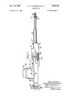
Fig. A1 Bott Full Back Position
Ll
Patent Application Publication Jun. 6, 2013 Sheet 2 of 7
US 2013/0139424 Al
Fig. A3 Prior Art
Fig. A4 Double Extractor Claw
Patent Application Publication Jun. 6, 2013 Sheet 3 of 7
US 2013/0139424 Al
Fig. B1 Operational Position
Fig. B3 Remove and Replace Barrel
Patent Application Publication Jun. 6, 2013 Sheet 4 of 7
US 2013/0139424 Al
Яд. Cl Static Position
21
Rotator Mechanism Depressed
19
22
20
23
26
Fig. G3 Extractor Claw Mechanism
22
20
23
Patent Application Publication Jun. 6, 2013 Sheet 5 of 7
US 2013/0139424 Al
Fig D1 Stowed Position
Fig D2 Removed Po&iton
58
Patent Application Publication Jun. 6, 2013 Sheet 6 of 7
US 2013/0139424 Al
Patent Application Publication Jun. 6, 2013 Sheet 7 of 7
US 2013/0139424 Al
big. F1 - Long Barrel with Butt Stock
Fig. F1 - Short Barrel no Butt Stock
Fig. Fl - Short Barrel no Butt Stock Axon
US 2013/0139424 Al
Jun. 6, 2013
1
MULTI CALIBER QUICKLY
RECONFIGURABLE AUTOMATIC MACHINE
GUN
DESCRIPTION OF DRAWINGS
[0001] Drawing A001—Ejector and Extractor Mechanism
(Plan Section)
[0002] FIG. Al—Bolt Full Back Position
[0003] FIG. A2—Bolt Full Forward Position
[0004] Drawing A002—Ejector and Extractor Mecha-
nism—Prior Art (Elevation)
[0005] FIG. A3—Prior Art
[0006] FIG. A4—Double Extractor
[0007] Drawing B001—Section of Barrel Reconfiguration
(Elevation Section)
[0008] FIG. Bl—Operational Position
[0009] FIG. B2—Open Position
[0010] FIG. B3—Remove and Replace Barrel
[0011] Drawing C001—Bolt Reconfiguration (Axon)
[0012] FIG. Cl—Static Position
[0013] FIG. C2—Rotator Mechanism Depressed
[0014] FIG. C3—Extractor Claw Mechanism
[0015] Drawing D001—Stock Storage (Axon)
[0016] FIG. DI—Stowed Position
[0017] FIG. D2—Removed Position
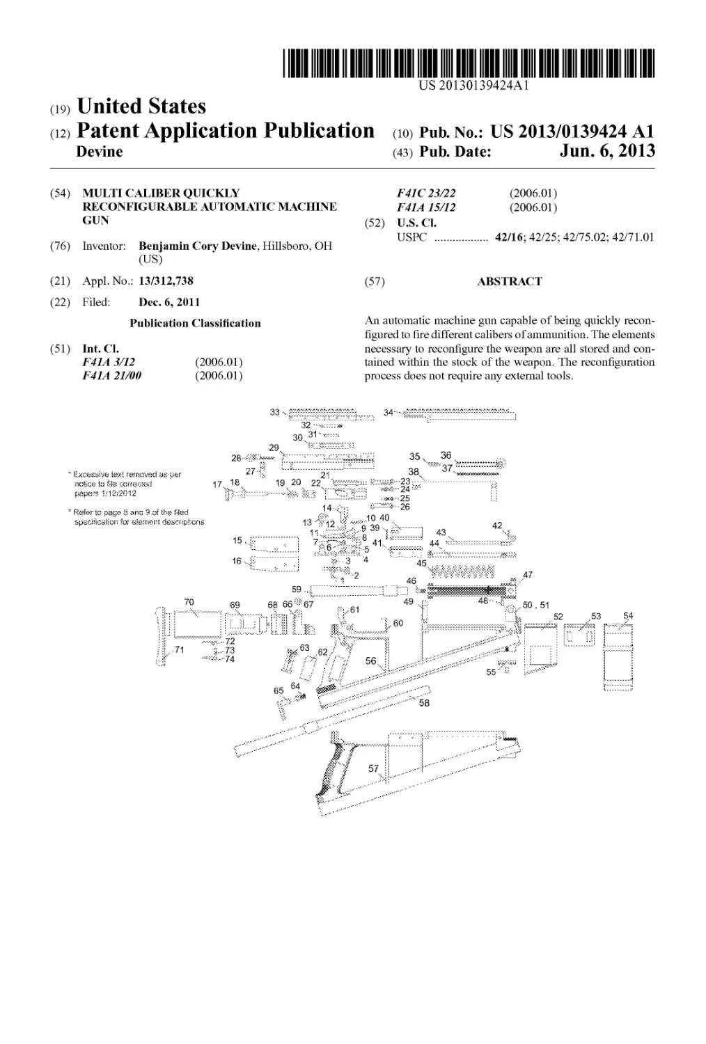
[0018] Drawing M001—Diagram of Parts (Exploded
Elevation)
[0019] Drawing F001—Examples of Preferred Embodi-
ment
[0020] FIG. Fl—Long Barrel and Butt Stock (Elevation)
[0021] FIG. F2—Short Barrel no Butt Stock (Elevation)
[0022] FIG. F3—Short Barrel no Butt Stock (Axon)
BACKGROUND OF INVENTION
General Purpose
[0023] The purpose for this gun design arises from the
varied battlefields and combat scenarios faced by US combat
forces throughout the world. This automatic machine gun is
designed with the ability to quickly and without the use of
tools switch barrels and bolts allowing the warfighter to
quickly reconfigure their weapon in the field of battle. Also as
part of this design the components used to reconfigure the
weapon are stored within compartments which are integrated
into the stock of the weapon. As an integrated weapons sys-
tem this design integrates all of the standard machine gun
design elements necessary to provide accurate and sustained
automatic fire as well as add the benefits of quick reconfigu-
ration to barrels of different length as well as barrels and bolts
of three different common military calibers. Furthermore, the
convenient storage of the components used for reconfigura-
tion on the weapon itself makes this design a self contained
weapons system.
SUMMARY OF INVENTION
[0024] This weapon is designed to be reconfigured to
handle three common military calibers 0.308, 0.223/5.
56X45, and 7.62X39. The weapon carries one bolt in the
operational position and one auxiliary Extractor Claw
Mechanism (23/24/25/26) in the storage position.
[0025] The weapon also carries one barrel in the operation
position and one auxiliary barrel in the storage position. The
weapon can deploy and store a barrel between 10" and 21"
This capability allows the warfighter to effectively configure
the weapon for engaging the enemy at long range as well as in
close quarters. This represents a significant advantage over
other modular weapons which can be reconfigured. The ele-
ments used to reconfigure other modular weapons must be
carried separately from the weapon and require the use of
tools to replace.
[0026] The bolt of this weapon can be quickly reconfigured
to handle different caliber ammunition by replacing the por-
tion of the bolt containing the extractor mechanisms without
replacing the entire operational bolt of the weapon.
[0027] The multiple extractor system gives 120 degrees of
extracting coverage (FIG. A4) at the base of the shell casing
verses less than 50 degrees on a modem AR style rifle (FIG.
A3). This innovation is achievable because one extractor also
acts as the ejector. When the bolt travels backward an ejector
ram hits a lug on the outside of the extractor. During this
action the Right Extractor (24) holds the right lip of the casing
while the Left Extractor (25) moves forward. A second lug on
the inside of the Left Extractor (25) strikes the back of the
casing forcing the cartridge out of the weapon.
DESCRIPTION OF PREFERRED EMBODIMENT
Description
[0028] The design is composed of a three part stock com-
prised of a Left Stock (55) Right Stock (56) and Magazine
Stock Bracket (52). The main components which are attached
to the stock include the Left Barrel Housing Hinge (50), Right
Barrel Housing Hinge (51), Magazine Receiver (53),
Receiver Block (49), Master Connector Bracket (61) and Butt
Stock Mount (66).
[0029] The Barrel Housing Closure (44), Bolt Pull Rod
Cover (34), Gas Piston (43), Front Sight (42), Charging
Handle Retainer (35) Charging Handle Spring (37), Charging
Handle (36) all attach to the Barrel Housing (47) while the
Main Spring (45), and the Bolt Pull Rod (38), go inside The
Barrel Housing (47). This assembly attaches to the Barrel
Housing Hinges (50,51). The Barrel (58 or 59) is inserted into
the Barrel Housing and the Barrel Housing Latch (46)
engages the receiver block to hold the Barrel Housing in
place.
[0030] The Trigger Assembly is comprised of the Trigger
Group Bracket (4), Trigger (1), Safety (2), Trigger Bolt (3),
Magazine Release (5), Hammer Bolt (6), Secondary Firing
Spring (7), Magazine Release Pin (8), Magazine Catch
Spring (9), Magazine Catch (10), Secondary Firing Mecha-
nism (11), Hammer Spring (12), Hammer Arrestor (13),
Hammer (14), Left Trigger Group Plate (15), Right Trigger
Group Plate (16). The Trigger Group Assembly is attached to
the stock with a pin though the Master Connector Bracket
(61).
[0031] The Bolt is comprised of the Bolt Slide (21) which is
screwed to the Bolt Body (22). The Rotator Mechanism is
inserted into the bolt body as well as the Firing Pin Spring
(19) and the F iring Pin (18) all of which is held in place by the
Bolt Closure (17). The Extractor Claw Mechanism is com-
prised of the Upper Extractor Claw Body (23), Lower Extrac-
tor Claw Body (26), Right Extractor Claw (24), Left Extractor
Claw (25). The Extractor Claw Mechanism is inserted into
Bolt.
[0032] The Upper is comprised chiefly of the Bolt Housing
Upper (29) and the Bolt Housing Pull Rod Cover (33).
Attached to these pieces are Extractor Ram Housing (30),
US 2013/0139424 Al
Jun. 6, 2013
2
Extractor Ram Spring (31), and Extractor Ram (32). This
assembly is attached to the weapon by a pin though the Bolt
Housing Upper Hinge (28) into the Butt Stock Mount (66).
The bolt is inserted into the slid rail of the Bolt Housing Pull
Rod Cover (33). The Upper is held in place when the Barrel
Housing assembly is locked into position.
Use
Reconfiguration:
[0033] One of the chief innovations of this design is the
weapons ability to quickly change barrels and bolts without
the use of tools. The Barrel (58 or 59) is replaced by sliding
the Barrel Housing Latch (46) on the side of the Barrel Hous-
ing (47) forward. The Barrel Housing (47) is secured to the
Stock (56/57) by the Bolt Housing Hinge (50/51) at the very
end of the forestock. Once the Barrel Housing Latch (46) is
slid forward the Barrel Housing (47) rotates upward on the
Bolt Housing Hinge (50/51) allowing the barrel to be
removed backwards out Barrel Housing (47).
[0034] The desired replacement barreled can then be
inserted into the Barrel Housing (47) through the Main Spring
(45) and through the yoke of the Bolt Pull Rod (38). (FIG. B2)
The Barrel Housing (47) is then rotated into the operational
position (FIG. Bl) locking the barrel into the weapon. A lug
near the breech of the barrel assures proper alignment of the
barrel. I rubber peg near the hinge tensions the barrel tight to
the stock increasing accuracy. The Barrel Housing Latch (46)
secures the Barrel Housing (47) into position for operation.
This simple system for barrel replacement makes a quick
reconfiguration of the weapon to handle barrels of different
lengths and caliber possible.
[0035] The bolt is reconfigured by removing the portion of
the bolt containing the Extractor Claw Mechanism (23/24/25/
26) from the Bolt Body (22) This is done by first opening the
Barrel Housing (47). The Master Assembly Pin (67) is then
rotated 90 degrees and removed partially allowing the Bolt
Housing Upper (29) to rotate rearward. The bolt can then be
slid forward out of the Bolt Pull Rod Cover (33) which is
affixed to the Bolt Housing Upper (29). To reconfigure the
bolt the Rotator Mechanism (20) is rotated counterclockwise
until fully depressed. This allows the Extractor Claw Mecha-
nism (23/24/25/26) to be rotated clockwise aligning the
retaining lugs with slots in the main bolt. This allows the
Extractor Claw Mechanism (23/24/25/26) to be slid forward
and removed from the Bolt Body (22).
[0036] With the Rotator Mechanism (20) fully depressed
the desired Extractor Claw Mechanism (23/24/25/26) can
then be inserted into the Bolt Body (22). Once the Rotator
Mechanism (20) is released the Extractor Claw Mechanism
(23/24/25/26) will be locked into the bolt.
[0037] This weapon also features a Main Spring (45) which
is forward of the bolt and surrounding the barrel. This feature
is designed to decreases muzzle rise and makes the overall
weapon shorter by eliminating a spring behind the bolt. This
spring pushes against the breech driving the Bolt Pull Rod
(38) forward pulling the bolt into the breech and engaging the
locking bolt locking lugs into the breech.
[0038] This design also features an automatically releasing
magazine. When the magazine is empty a spring within the
magazine follower pushes a stud through the magazine catch
hole pushing the magazine catch out of the magazine and
releasing the magazine to fall free of the weapon.
Bolt Slam Automatic Action:
[0039] The automatic fire capability of this weapon is
achieved by utilizing the forward motion of the bolt to release
the hammer. The first shot is fired by pulling the Trigger (1)
rearward. This releases the Hammer Arrestor (13) thus releas-
ing the Hammer (14) to strike the Firing Pin (18). As the
Hammer (14) strikes the Firing Pin (18) the cartridge is dis-
charged. High pressure gas exits through a hole in the barrel
and is released into the Bolt Pull Rod (38). This forces the
Bolt Pull Rod (38) and equally the bolt rearwards. As the bolt
travels rearward the Hammer (14) is forced down engaging
the Hammer Arrestor (13). As the bolt slides forward the
hammer tensions the Hammer Arrestor (13) which is stopped
in position by the Secondary Firing Mechanism (11). As the
bolt travels forward it trips the Secondary Firing Mechanism
(11) which releases the Hammer Arrestor (13) which in turn
releases the Hammer (14) starting the firing cycle over again.
Double Extractor Claw:
[0040] The Extractor Claw Mechanism (FIG. Al and A2)
of this weapon features a Left Extractor Claw (25) and Right
Extractor Claw (24). This provides a positive extraction of the
empty cartridge from the barrel chamber. (FIG. Al) The Right
Extractor Claw (24) is stationary while the Left Extractor
Claw (25) moves forward when engaged by the Extractor
Ram (32) upon cocking the bolt into the fully rearward posi-
tion or in firing when the Bolt Pull Rod (38) moves the bolt
fully rearward.
Reconfiguration Unit Storage:
[0041] The ability of this gun to store an extra Extractor
Claw Mechanism (23/24/25/26) and Barrel (58/59) within the
weapon itself is a significant battlefield advantage. The Barrel
(58/59) is stored in a tube which is an integrated part of the
Stock (56/57). A spring loaded Barrel Tube Lid (65) at the
lower end of tube retains the barrel within the tube. The extra
Extractor Claw Mechanism (23/24/25/26) is stored in the
Extractor Claw Dock (62) which slides into handle of the
weapon. The Extractor Claw Dock (62) is slid out the side of
the handle to access the Extractor Claw Mechanism (23/24/
25/26).
Manufacturing
[0042] 1 . The stock is injection molded from Impact Resis-
tant ABS plastic. The stock is composed of a Left Stock (56),
a Right Stock (57), and a Magazine Stock Bracket (52) These
pieces are assembled using standard screws and ferrules. The
Bolt Housing Closure (44), Extractor Claw Dock (62), Butt
Stock (70), and Butt Stock Pad (71) are also constructed of
Impact Resistant ABS plastic.
[0043] 2 . All Barrels (58/59) are constructed of lathed stain-
less steel
[0044] 3. Bolt Pull Rod Cover (34) and Bolt Housing Pull
Rod Cover (33) are cast from steel and milled to reach final
finished state.
[0045] 4. All bolt elements include Rotator Mechanism
(20) Bolt Body (22) Firing Pin (18) Bolt Closure (17) Extrac-
tor Claw Mechanism (23/24/25/26) are constructed of milled
stainless steel. The Bolt Closure screws into the back of the
Bolt Body retaining the Bolt Spring (19) Rotator Mechanism
(20) and Firing Pin (18) within the Bolt Body (22) The
Extractor Claw Mechanism is constructed by placing the lugs
US 2013/0139424 Al
Jun. 6, 2013
3
of the Right Extractor Claw (24) and the Left Extractor Claw
(25) into the slots on the Extractor Claw Lower (26). The
Extractor Claw Upper (23) is then placed on top and the edges
of the Extractor Claw Upper (23) and Extractor Claw Lower
(26) are welded together.
[0046] 5. All other metallic pieces including Trigger (1),
Safety (2), Trigger Bolt (3), Trigger Group Bracket (4),
Magazine Release (5), Hammer Bolt (6), Magazine Release
Pin (8), Magazine Catch (10), Secondary Firing Mechanism
(11), Hammer Arrestor (13), Hammer (14), Left Trigger
Group Plate (15), Right Trigger Group Plate (16), Bolt Hous-
ing Upper Latch (27), Bolt Housing Upper Hinge (28), Ejec-
tor Ram Housing (30), Ejector Ram (32), Charging Handle
Retainer (35), Charging Handle (36), Bolt Pull Rod (38),
Receiver Cover (40), Receiver Cover Bracket (41), Front
Sight (42), Gas Piston (43), Barrel Housing Latch (46), Barrel
Housing (47), Receiver Block (49), Left Barrel Housing
Hinge (50), Right Barrel Housing Hinge (51), Trigger Guard
(60) Master Connector Bracket (61), Barrel Tube Lid (64)
Butt Stock Mount (66), Master Assembly Pin (67), Butt Stock
Bracket (68), Butt Stock Arm (69), Catch Bracket (72), Catch
(73), Catch Lever (74) are constructed of milled stainless
steel. All metal elements are parkerized on faces not subj ect to
abrasion and wear.
[0047] 6. The Magazine Receiver (53) is stamped and
formed from sheet steel. The Magazine (54) is constructed of
punched sheet steel elements held together by punched sheet
steel elements spot welded into position.
[0048] 7. The Barrel Tensioning Block (48) is constructed
of vulcanized rubber
[0049] 8 . All screws and ferrules are hardware store grade.
[0050] 9. All operational springs are constructed of spring
steel.
1. A bolt which can be reconfigured to hold and fire car-
tridges of different calibers by means of replacing and or
otherwise modifying the portion of the bolt containing the
mechanism for holding and or extracting the cartridge. (FIG.
Cl, C2, C3) The portion of the bolt containing the mechanism
for holding and or extracting the cartridge may also include
other elements including but not limited to firing pin, firing
pin spring, and any mechanisms used to rotate the bolt for
locking into the breech, excluding only the main housing used
to contain these parts conventionally.
2. A cartridge extractor system where, one or more of the
mechanisms used to extract the cartridge from the weapon
chamber, is also used as the mechanism which ejects the
cartridge from the breech of the weapon. (FIG. Al, A2)
3. And where multiple extractors interface the cartridge
from disconnected positions around the axis of the center of
the cartridge. (FIG. A4)
4. A weapon where the barrel is inserted into a mechanism
rotating parallel to the length of the barrel with the purpose of
removing and replacing the barrel. The mechanism is rotated
away from the weapon to remove the barrel and rotated into
operational position when the barrel is ready for firing action.
(FIG. Bl, B2, B3)
5. A weapon where the components for reconfiguring the
weapon are stored in the body of the weapon for quick access.
A weapon which has space to hold the extra bolt adapter
mechanism comprised of the portion of the bolt for holding
and or extracting the cartridge and which also has space to
hold at least one extra replacement barrel. (FIG. DI, D2)