/


Tags: weapons military affairs machine gun firearms
Year: 1917
Similar


Text
No. 1758
HANDBOOK OF THE
COLT AUTOMATIC MACHINE GUN
CALIBER .30
WITH
PACK OUTFITS AND ACCESSORIES
{SIXTEEN PLATES)
AUGUST 17, 1901
REVISED APRIL 13; 1903
REVISED MAY 1, 1905
REVISED JULY 25, 1906
REVISED DECEMBER 21, 1907
REVISED MARCH 20, 1913
REVISED JULY 31, 1916
WASHINGTON
GOVERNMENT PRINTING OFFICE
1917
War Department,
Office of the Chief of Ordnance,
Washington, July 31,1916,
This manual is published for the information and government of the Regular
Army and National Guard of the United States.
By order of the Secretary of War:
William Crozier,
Brigadier General, Chief of Ordnance,
8
LIST OF PLATES.
* Faces page —
I. Gun, mounted on tripod___________________________________________ 7
II. Gun, sectional views______________________________________________ 8
III. Gun components___________________________________________________ 10
IV. Sights___________________________________________________________ 15
V. Tripod and mount_________________________________________________ 18
VI. Belt loading machine components__________________________________ 24
VII. Pack harness______________________________________________________ 28
VIII. Pack harness_____________________________________________________ 29
IX. Aparejo, model of 1911; frame (right half)_______________________ 30
X. Pack, first mule (right side)____________________________________ 32
XI. Pack, first mule (left side)_____________________________________ 33
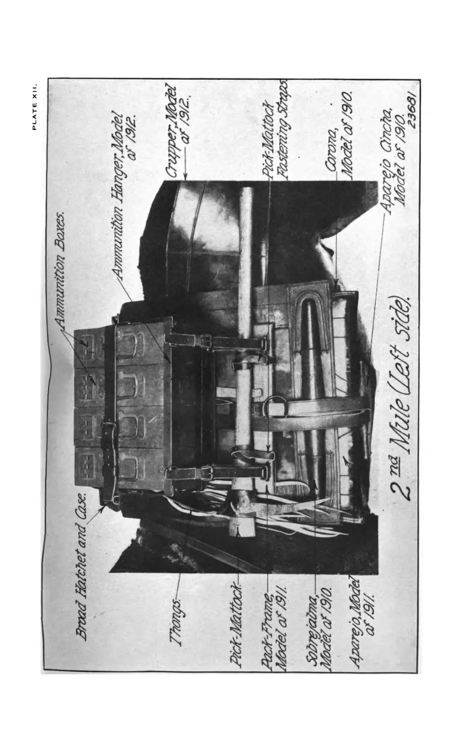
XII. Pack, second mule (leftside)______________________________________ 34
XIII. Pack, third mule (right side)____________________________________ 35
XIV. Pack, fourth mule (right side)___________________________________ 36
XV. Pack, fourth mule (left side)___________________________________ 37
XVI. Carriage_________________________________________________________ 49
5
PLATE?!.
COLT AUTOMATIC MACHINE GUN, CALIBER .30, MOUNTED ON TRIPOD.
HANDBOOK OF THE COLT AUTOMATIC MACHINE GUN,
CALIBER .30.
EQUIPMENT OF MACHINE-GUN COMPANY OR TROOP.
Each machine-gun company or troop is provided with four guns,
including tripods, ammunition, spare parts, tools, and accessories, to-
gether with the necessary packs.
The equipment of each organization is carried on 16 mules, consti-
tuting 4 sections of 4, mules each. The sections are essentially com-
plete units, although certain articles are not carried in every section.
The equipment of each section consists of one gun, ammunition,
and the necessary equipment for maneuvering the piece in the field.
It is divided into the following parts:
Part I. The gun with its ammunition and accompanying parts.
Part II. The pack harness.
Part III. The special pack equipment.
Part IV. The pioneer tools.
A description of each of these parts, together wth a statement of
total equipment issued to one machine-gun company or troop, fol-
lows:
PART I. THE GUN WITH ITS AMMUNITION AND ACCOMPANYING
PARTS.
DESCRIPTION OF COLT AUTOMATIC MACHINE GUN, CALIBER .30, AND
PARTS--GENERAL.
[Plates I to IV.]
The Colt automatic machine gun, caliber .30, belongs to that class
of automatic guns in which the power required to operate it is
obtained from the powder gas and is self-operating after one shot
has been fired as long as the trigger is held back and the ammunition
supplied. Plate I shows the gun mounted on tripod with ammu-
nition box attached.
The gun consists of a barrel attached to a breech casing which
contains the mechanism for extracting and ejecting the empty case,
moving the feed belt along the required distance, withdrawing a
cartridge from the belt, placing it in the chamber, closing the bolt
on it, and firing it. The force required to perform these different
motions is derived from the powder gases, a portion of which after
8 HANDBOOK OF COLT AUTOMATIC MACHINE GUN, CAL. .30.
each discharge passes through a small radial vent in the barrel some-
what in rear of the muzzle and operates a lever connected with the
breech mechanism.
The cartridges are automatically fed to the gun by means of canvas
belts, which are coiled in boxes readily attached to the breech casing.
The boxes will hold two belts of 120 cartridges each, and moving
with the casing insure a continuous supply of cartridges undisturbed
by the vertical or horizontal movement of the gun.
In operating the gun the feed belt is entered and the lever is thrown
down and rearward (once by hand) as far as it will go; this opens
the breech and feeds the first cartridge from the belt to the carrier;
the lever is then released and the springs cause it to swing forward,
close the vent in the barrel, and transfer the cartridge from the car-
rier to the barrel, also cocking the hammer and closing and locking
the breech. On pulling the trigger the cartridge is fired, and after
the bullet has passed the vent and before it leaves the muzzle the
powder gases expand through the radial vent upon the piston on
the end of the gas lever, which, forced downward and to the rear,
opens the breech, ejects the empty case, and feeds to the carrier
another cartridge. The gas lever, returning under the action of the
springs, forces the cartridge into the chamber and closes and locks
the breech. If, instead of releasing the trigger, it is held back, the
cartridge is fired and the same operation will be repeated until the
cartridges in the feed belt are exhausted, providing a continuous fire
at the rate of about 400 shots per minute.
The following table gives a serial list of component parts of the
gun, mount, and tripod:
SERIAL LIST OF COMPONENT PARTS.
THE GUN.
[The numbers before the components refer to numbers shown on Plates II, III, and IV.]
1. Handle.
2. Handle lock.
3. Handle-lock stop and safety stop.
4. Handle-lock stop spring and safety
stop spring.
5. Handle-lock stop screw and safety
stop screw.
6. Hammer.
7. Mainspring.
8. Trigger.
9. Trigger spring.
10. Sear.
11. Sear spring.
12. Trigger and sear pin.
13. Bolt.
14. Bolt pin.
15. Shell extractor.
16. Shell-extractor spring.
17. Shell-extractor pin.
18. Firing pin.
19. Firing-pin spring.
20. Firing-pin lock.
21. Carrier.
22. Carrier pin.
23. Carrier dog.
24. Carrier-dog pin.
25. Carrier-dog spring.
26. Carrier-dog plunger.
27. Gas cylinder.
28. Gas-cylinder pin.
29. Gas lever.
30. Gas-lever pin.
31. Gas-lever connection.
32. Gas-lever connection pin.
HANDBOOK OF COLT AUTOMATIC MACHINE GUN, CAL. .30. 9
33. Gas-lever bracket.
34. Gas-lever bracket pin.
35. Gas-lever piston.
36. Gas-lever piston pin.
37-38. Retracting springs.
39. Retracting-spring tube, right-hand.
40. Retracting-spring tube, left-hand.
41-42. Retracting-spring followers.
43-44. Retracting-spring tube screws.
45. Retracting connection.
46. Retr acting-connect ion link, long,
rivet.
47. Retracting-connection link, long.
48. Retracting-connection link, short,
rivet.
49-50. Retracting-connection links,
short.
51. Retracting-connection pin.
52. Stock, right-hand, with escutcheon.
53. Stock, left-hand, with escutcheon.
54. Stock screw.
55. Front-side plate screw.
56. Front-side plate screw lock screw.
57. Rear-side plate screw.
58. Safety latch.
59. Belt guide.
60. Belt-guide screw.
61. Feed wheel and bushing.
62. Feed-wheel shaft.
63. Feed-wheel dog.
64. Feed-wheel dog screw.
65. Feed-wheel dog spring.
66. Feed lever.
67. Feed-lever screw.
68. Feed throw-off.
69. Feed throw-off spring.
70. Feed throw-off screw.
71. Ratchet lever.
72. Ratchet-lever screw.
73. Ratchet-lever pawl.
74. Ratchet-lever pawl spring.
75. Ratchet-lever pawl pin.
76. Ejector.
77. Chamber guide.
78. Bullet guide.
79. Bullet-guide screw.
80. Catridge guide.
81. Rear side plate screw lock screw.
82. Cartridge extractor.
83. Cartridge-extractor pin.
84. Cartridge-extractor spring.
85. Trip.
86. Slide.
87. Slide pin.
88. Receiver.
89. Side plate, right-hand.
90. Side plate, left-hand.
91. Bottom plate.
92. Barrel.
93. Front sight, complete.
94. Rear sight, complete.
95. Front sight.
96. Front sight screw.
97. Cover screws.
98. Front sight cover.
99. Windage screw.
100. Pivot spring.
101. Windage screw knob.
102. Half nut spring.
103. Half nut.
104. Windage screw collar.
105. Elevating screw head.
106. Elevating screw.
107. Slide cap screw, large.
108. Windage screw spring.
109. Elevating screw pin.
110. Pivot.
111. Slide cap screw, small.
112. Windage screw pin.
113. Drift slide.
114. Leaf.
115. Aperture disk.
116. Leaf joint pin.
117. Slide cap.
118. Base spring.
119. Slide body.
120. Movable base.
121. Rear sight fixed base.
THE MOUNT.
[Numbers before components refer
to numbers on Plate V.]
1. Saddle, with arc. 2. Yoke. 3. Worm. 4. Worm shaft. ,5. Worm-shaft screw. 6. Worm-shaft screw washer. 7. Hand wheel. 8. Handwheel screw. 9. Gun pin. 10. Gun-pin lock screw (not shown). 11. Gun-pin chain. 12. Gun-pin chain screw. 13. Axis bolt. 14. Axis-bolt nut.
10 HANDBOOK OF COLT AUTOMATIC MACHINE GUN, CAL. .30.
15. Gun-adjusting screw. 16. Gun-adjusting screw nut. 22. Spindle washer. 23. Spindle-washer bolt.
17. Arc clamp. 24. Shoulder rest.
18. Arc-clamp stop screw (not shown). 25. Shoulder-rest tube.
19. Arc-clamp shoe (not shown). 20. Worm cover. 21. Worm-cover screw. 26. Shoulder-rest pin. 27. Shoulder-rest clamp.
THE TRIPOD.
[Numbers before components refer to numbers on Plate V.]
28. Socket.
29. Mount clamp.
30. Mount-clamp screw.
31. Mount-clamp shoe.
32. Leg bolts (3).
33. Leg-bolt nuts (3).
34. Leg, long.
35. Leg, short (2).
36. Saddle.
37. Saddle thumbscrew.
38. Saddle bracket.
39. Saddle-bracket clamp.
40. Saddle-bracket rod.
The following table gives an alphabetical list of component parts
of the gun, mount, and tripod:
ALPHABETICAL LIST OF COMPONENT PARTS.
THE GUN.
[Numbers after components refer to numbers shown on Plates II, III, and IV.]
Aperture disk (115).
Barrel (92).
Base spring (118).
Belt guide (59).
Belt-guide screw (60).
Bolt (13).
Bolt pin (14).
Bottom plate (91).
Bullet guide (78).
Bullet-guide screw (79).
Carrier (21).
Carrier dog (23).
Carrier-dog pin (24).
Carrier-dog plunger (26).
Carrier-dog spring (25).
Carrier pin (22).
Cartridge extractor (82).
Cartridge-extractor pin (83).
Cartride-extractor spring (84).
Cartridge guide (80).
Chamber guide (77).
Cover screws (97).
Drift slide (113).
Ejector (76).
Elevat ing-screw (106).
Elevating-screw head (105).
Elevating-screw pin (109).
Feed lever (66).
Feed-lever scr’few (67).
Feed throw-off (68).
Feed throw-off screw (70).
Feed throw-off spring (69).
Feed wheel and bushing (61).
Feed-wheel dog (63).
Feed-wheel dog screw (64)
Feed-wheel dog spring (65).
Feed-wheel shaft (62).
Firing pin (18).
Firing-pin lock (20).
Firing-pin spring (19).
Fixed-base screw (three) (not shown).
Front-side plate screw (55).
Front-side plate screw lock screw (56).
Front sight (95).
Front sight, complete (93).
Front-sight cover (98).
Front-sight screw (96).
Gas cylinder (27).
Gas-cylinder pin (28).
Gas lever (29).
Gas-lever bracket (33).
Gas-lever bracket pin (34).
Gas-lever connection (31).
Gas-lever connection pin (32).
Gas-lever pin (30).
Gas-lever piston (35).
л at &
Plate III, Gun components.
HANDBOOK OF COLT AUTOMATIC MACHINE GUN, CAL. .30.
11
Gas-lever pin (36).
Half nut (103).
Half-nut spring (102).
Hammer (6).
Handle (1).
Handle lock (2).
Handle-lock stop (3).
Handle-lock stop spring (4).
Handle-lock stop screw (5).
Leaf (114).
Leaf-joint pin (116).
Mainspring (7).
Movable base (120).
Pivot (110).
Pivot spring (100).
Ratchet lever (71).
Ratchet-lever pawl (73).
Ratchet-lever pawl pin (75).
Ratchet-lever pawl spring (74).
Ratchet-lever screw (72).
Rear-side plate screw (57).
Rear-side plate screw lock screw (81).
Receiver (88).
Rear sight, complete (94).
Rear-sight fixed base (121).
Retracting connection (45).
Retracting-connection link, long (47).
Retracting-connection link, long, rivet
(46).
Retracting-connection link, short (49-
50).
Retracting-connection link, short, rivet
(48).
Retracting-connection pin (51).
Retracting spring (37-38).
Retracting-spring followers (41-42).
Retracting-spring tube, left hand (40).
Retracting-spring tube, right Hand
(39).
Retracting-spring tube, screws (43-44).
Safety latch (58).
Safety stop (3).
Safety-stop screw (5).
Safety-stop spring (4).
Sear (10).
Sear spring (11).
Shell extractor (15).
Shell-extractor pin (17).
Shell-extractor spring (16).
Side plate, left hand (90).
Side plate, right hand (89).
Slide (86).
Slide body (119).
Slide cap (117).
Slide-cap screw, large (107).
Slide-cap screw, small (111).
Slide pin (87).
Stock, left hand, with escutcheon (53).
Stock, right hand, with escutcheon
(52).
Stock screw’ (54).
Trigger (8).
Trigger spring (9).
Trigger and sear pin (12).
Trip (85).
Windage screw (99).
Windage-screw collar (104).
Windage-screw knob (101).
Windage-screw pin (112).
Wmdage-screw’ spring (108).
THE MOUNT.
[Numbers after components refer to numbers on Plate V.]
Arc clamp (17).
Arc-clamp screw (19) (not shown).
Arc-clamp stop screw (18) (not
showrn).
Axis bolt (13).
Axis-bolt nut (14).
Gun-adjusting screw (15).
Gun-adjusting screw nut (16).
Gun pin (9).
Gun-pin chain (11).
Gun-pin chain screw (12).
Gun-pin lock screw (10) (not shown).
Hand wheel (7).
Hand wheel screw’ (8).
Saddle, with arc (1).
Shoulder rest (24).
Shoulder-rest clamp (27).
Shoulder-rest pin (26).
Shoulder-rest tube (25).
Spindle washer (22).
Spindle-wrasher bolt (23).
Worm (3).
Worm cover (20).
Worm-cover screw (21).
W?rm shaft (4).
Worm-shaft screw (5).
Worm-shaft screw washer (6).
Yoke (2).
12 HANDBOOK OF COLT AUTOMATIC MACHINE GUN, CAL. .30.
THE TRIPOD.
[Numbers after components refer to numbers on Plate V.]
Leg, long (34). Leg, short (two) (35). Leg bolts (three) (32). Leg-bolt nuts (three) (33). Mount clamp (29). Mount-clamp screw (30). Mount-clamp shoe (31). Saddle (36). Saddle bracket (38). Saddle-bracket clamp (39). Saddle-bracket rod (40). Saddle thumbscrew (37). Socket (28). Tripod leg-fastening clip with bolt (not shown).
DETAILED DESCRIPTION OF THE GUN, MOUNT, AND TRIPOD.
THE GUN.
Plate II, figure 1, shows the gun partly in section and partly in
elevation, with the parts in their normal position. Figure 2 of the
same plate shows the position of the parts when the gas lever is in its
extreme rear position. On Plate III are shown all the different parts
of the gun except the front and rear sights, barrel, receiver, and side
and bottom plates. Plate IV shows the front and rear sights.
The barrel^which is made very heavy in order to reduce vibration
and to minimize the effect of heat generated by continuous firing, is
screwed into a framje or receiver, in which the breech mechanism is
contained. One extra barrel is issued with each gun, carefully fitted
and marked with the number of the gun to which it pertains. The
barrels for these guns are not interchangeable. A special vise and
two wrenches are kept on hand at Springfield Armory and the several
ordnance depots for replacing the barrels.
The side plates, only one of which is shown in Plate II, and the
bottom plate, are secured to the receiver by means of the two side-
plate screws and the side-plate lock screws. The two parts last men-
tioned are not shown in Plate II.
The gas cylinder and the gas-lever bracket both fit closely around
the barrel and are connected together by the gas-cylinder pin and by
the front side-plate screw, which passes through them both and
through both side plates. They are not secured to the barrel, how-
ever, by any fixed connection, and the barrel slides through them
when expanded by heat in firing.
The gas lever swings in a vertical plane about the gas-lever bracket
pin, which secures it to the gas-lever bracket. The gas-lever piston,
which fits in the gas cylinder, is attached to the forward end of the
gas lever by means of the gas-lever piston pin and has a slight motion
about this pin to enable it to move freely in and out of the cylinder
as the lever swings about its pivot. The ends of the gas-lever pin,
projecting on both sides of the gas lever, furnish a convenient hold
for operating the gas lever by hand. If the gas-lever pin is hot from
HANDBOOK OF COLT AUTOMATIC MACHINE GUN, CAL. .30. 13
continuous firing, the operating handle, one of the accessories, should
be used.
The gas lever is held in its forward position, as shown in Plate II,
figure 1, by the action of two retractor springs which lie side by side
below the barrel and which are contained in the retracting-spring
tubes, held by the retracting-spring tube screws. Only one set of
these parts is shown in Plate II, as both sets lie in the same pro-
jection. The retracting springs act on the gas lever through the
retracting connection, the two retracting-connection links, short, the
retracting-connection link, long, the two retracting-connection link
rivets, and the retracting-connection pin. Only one of the retracting-
connection links, short, is shown in Plate II.
The retracting connection is a T-shaped piece, the two short arms
of which bear on the followers and hold the springs under slight
compression. (Only one follower is shown in the figure, as they both
lie in the same projection.)
If the gas lever be swung downward and to the rear it compresses
the retractor springs, as shown in Plate II, figure 2, and when it is
released it flies back to its original position under the action of these
springs. The backward movement of the gas lever is limited by the
bottom plate, which it strikes as it swings to the rear.
As the gas lever swings backward and forward its motion is com-
municated to the slide by means of the gas-lever connection, which
is attached to the gas lever by the gas-lever connection pin and to the
slide by the slide pin.
The slide works in grooves in the walls of the receiver and is
further guided by the slide pin, the rectangular ends of which move
in slots in the side plates.
The cartridge extractor is pivoted to the slide by the cartridge-
extractor pin and is acted upon by the cartridge-extractor spring.
This pin also carries the cartridge guide, which is a spring-tempered
steel piece that guides the cartridge into the receiver as it is being
lifted by the carrier.
The belt guide, secured to the receiver by the belt-guide screw, as-
sists in guiding the belt and serves also in preventing “ bunching ”
of the belt into the channel between the two sides of the slide.
The carrier, which is pivoted to the receiver by the carrier pin,
receives the cartridge when extracted from the belt by the backward
movement of the slide.
The carrier dog is pivoted to the rear end of the carrier by the
carrier-dog pin and is free to rotate backward and downward as the
slide moves to the rear over it. When cleared by the slide it resumes
its normal position under the force of the carrier-dog spring, oper-
ating the carrier-dog plunger.
14 HANDBOOK OF COLT AUTOMATIC MACHINE GUN, CAL. .30.
As the slide moves forward it rides over the curved surface of the
dog, depressing it and causing the front end of the carrier to rise and
lift the cartridge in front of the bolt, which pushes it into the
chamber.
On the right side of the slide are two lugs which operate the feed
lever, which is pivoted on the feed-lever screw. A stud on the side of
the feed lever works in a slot in the ratchet lever, which pivots on the
ratchet-lever screw. When the slide moves to the rear the ratchet
lever rises and the ratchet-lever pawl is forced back against the
ratchet-lever pawl spring by the sloping surface of the face of the
feed wheel. The feed wheel and bushing are free to turn on the
feed-wheel shaft.
When the pawl reaches the upper flat side of the tooth of the feed
wheel it is forced out and rests on top of the tooth.
As the slide moves forward the ratchet lever is forced down and
the pawl moves the feed wheel forward one notch.
Backward motion of the feed wheel is prevented by the feed-wheel
dog, which pivots on the feed-wheel dog screw, and is acted upon by
the feed-wheel dog spring. A feed throw-off, with its spring, is pro-
vided, by means of which the feed wheel may be released and a
partially fired belt of cartridges removed when desired. The throw-
off is operatedby means of a knurled head on the feed throw-off
screw on the right side of the gun just below the belt exit. (The
throw-off and spring and screw are not shown in Plate II.)
The bolt is cylindrical in shape, with the sides cut away somewhat
to lighten it. It carries the shell extractor, the shell-extractor spring,
the shell-extractor pin, the firing pin, the firing-pin spring, and the
firing-pin lock. The shell-extractor spring and pin and the firing-
pin spring are not shown in Plate II. A short guide rib on the
under side of the bolt near the rear projects downward through a
slot in the slide, to which it is secured by the bolt pin.
This pin passes through a cam-shaped slot in the guide rib and as
the slide moves backward and forward it communicates a vertical as
well as a backward and forward movement to the bolt.
When the gas lever is in its normal position, as shown in Plate II,
figure 1, the rear of the bolt is locked against two recoil shoulders on
the frame. As the slide moves to the rear the rear end of the bolt is
first raised until it clears the recoil shoulders and is then carried to
the rear by the slide.
The hammer, mainspring, trigger, trigger spring, sear, sear spring,
and trigger and sear pin are all contained in the handle. The handle
is provided with the stock, right hand, with escutcheon, and stock,
left hand, with eschutcheon, held by the stock screw. These parts,
with the exception of the handle, are not shown in Plate II. The
handle lock, with its handle-lock stop, handle-lock stop spring, and
handle-lock stop screw, are for the purpose of locking the handle to
PLATE IV.
SIGHTS.
HANDBOOK OF COLT AUTOMATIC MACHINE GUN, CAL. .30. 15
the receiver. These parts are on the right side of the receiver and do
not appear in Plate II.
In moving to the rear the bolt pushes the hammer backward against
the mainspring, and when the hammer is in its extreme rear position
the sear and the trigger both engage in the notch at its forward
end, as shown in Plate II, figure 2.
It is necessary for both sear and trigger to engage the hammer,
because in automatic firing the trigger is held back all the while,
so that the sear must be depended upon to hold the hammer until
the breech is closed and locked. In automatic firing the sear is
released at the moment of firing by a trip. This trip is in the form
of a lever and is pivoted at its middle point; when the slide is to
the rear, its forward end rests in a groove cut in the slide. As the
slide approaches its extreme forward position, the forward end of
the trip rides up an inclined surface to the top of the slide and thus
depresses the rear end of the trip, which in turn disengages the sear
from the hammer.
The ejector, not shown on Plate II, is located in a groove in the
left side of the receiver in such a position that a projecting lug on
its inner side is struck by the head of the case when the latter is
clear of the chamber.
The safety latch is operated by means of a thumb piece on the
right of the receiver. When the thumb piece is pushed forward,
the safety latch rises in front of the hammer and holds it in its back-
ward position. In this position the thumb piece is held by the
safety stop, the parts of which are the same as those of the handle-
lock stop. The safety lock is to be used only when a loaded cartridge
is left in the chamber.
Air pump: The hammer of this gun, working as it does in the
cylindrical portion of the handle, serves as the piston of an air pump,
and each backward motion of the hammer forces a jet of air through
a tube extending along the top of the receiver to the mouth of the
chamber of the piece. This jet of air has a slight cooling effect and
serves to keep the chamber free from unburned grains of powder.
SIGHTS.
The front sight, shown on Plate IV, has on its upper portion a
thin leaf slightly beveled to the front, and on each side is cut a cir-
cular groove to better define the sight proper. The lower portion
consists of a dovetail base, which engages in a dovetail groove on
the barrel. The front sight is secured in position by the front sight
screw, which bears against the top surface of the dovetail cut in
the barrel. Over the front sight is placed the front sight cover
secured by the cover screws.
16 HANDBOOK OF COLT AUTOMATIC MACHINE GUN, CAL. .30.
The rear sight complete, shown on Plate IV, is made up of the
following principal parts: The movable base, the base spring, the
leaf, the elevating screw, the slide, the half nut, the slide cap, the
drift slide, the aperture disk, and the windage screw.
The movable base has on its upper surface two ears in which are
the holes for the joint pin which serves as a hinge for the leaf. On
the rear end of the movable base are the wind-gauge graduations,
each point of which corresponds to a lateral deviation of 4 inches
for each 100 yards. Both ends have lips which fit the undercuts of
the fixed base, the front lip having also a worm gear for engaging
the thread of the windage screw. The base spring fits in the spring
seat of the movable base.
The leaf is graduated from 0 to 2,800 yards. On the right side
of the sighting opening in the leaf is the groove and seat for the
elevating screw, which is a long thin screw, extending from the
bottom of the sighting opening to the top of the leaf, where it is
secured in the elevating screw head by the elevating screw pin. This
elevating screw allows minute corrections for elevation and also holds
the slide ip" position on the leaf by means of a half nut which is
seated in the slide and the half-nut spring, the latter forcing the
half nut against the thread on the elevating screw. The outer end
of this half nut is knurled and by pressing in on the knurled head
the half nut can be released from the elevating screw and the slide
quickly raised or lowered.
The rear face of the slide is cut out for the leaf and the drift slide
and the right half is made with a seat for the half-nut spring and
the half nut. The right and left ends are drilled and tapped for
the small slide cap screw, and the large slide cap screw, which secure
the slide cap to the slide. The front face of the slide is slotted and
recessed for the pivot.
The slide cap has the seat for the aperture disk, and also aperture
for sighting, and for reading the graduation on the leaf. The center
is slotted for the pivot. On the right and left sides are drilled the
boles for the small and large slide cap screws. On the rear face at
the bottom of the slide cap is the open or battle sight.
The drift slide moves in the drift slots in the leaf. At the top
is a small open sight, while just below are two openings, the upper
for the pivot and circular lug on the aperture disk and the lower for
a sighting aperture. The drift slide is held in place by a lug on its
front face, which bears against the slide, and by the lug which con-
tains the open sight. This latter lug extends to the rear and bears
against the top of the slide cap* On the lower edge of the open
sight lug is another small lug which engages in the notches in the
perimeter of the aperture disk, locking the latter in the desired
position
HANDBOOK OF COLT AUTOMATIC MACHINE. GUN, CAL. .30. 17
The aperture disk is a circular piece containing five sight openings,
viz, four peepholes, 0.04, 0.06, 0.08, and 0.10 inch in diameter,
and one large aperture which contains an open sight. A circular
lug on the front face engages in the central opening of the drift
slide, thus causing the aperture disk to conform to the movement of
the former. This lug is drilled and tapped for the pivot spring and
the pivot. The purpose of the pivot spring is to force the aperture
disk to the rear, so that one of the notches, which are cut on the
perimeter of the latter, will engage in the small lug on the drift
slide and prevent rotation. By pressing inward, the aperture disk
can be released and rotated until the desired aperture is opposite
the sighting opening in the drift slide.
The windage screw complete consists of the windage screw, the
windage screw knob, the windage screw collar, the windage screw
spring, and the windage screw pin. It is seated in the front part
of the fixed base.
The rear sight is attached to the gun by the rear sight fixed base,
the latter being secured to the barrel by three fixed base screws.
The rear sight fixed base contains the pivot lug for the movable
base and a lug on the rear end, which forms an undercut for the lip
on the rear end of the movable base. Upon its rear upper surface
are two zero marks and the wind gauge graduations.
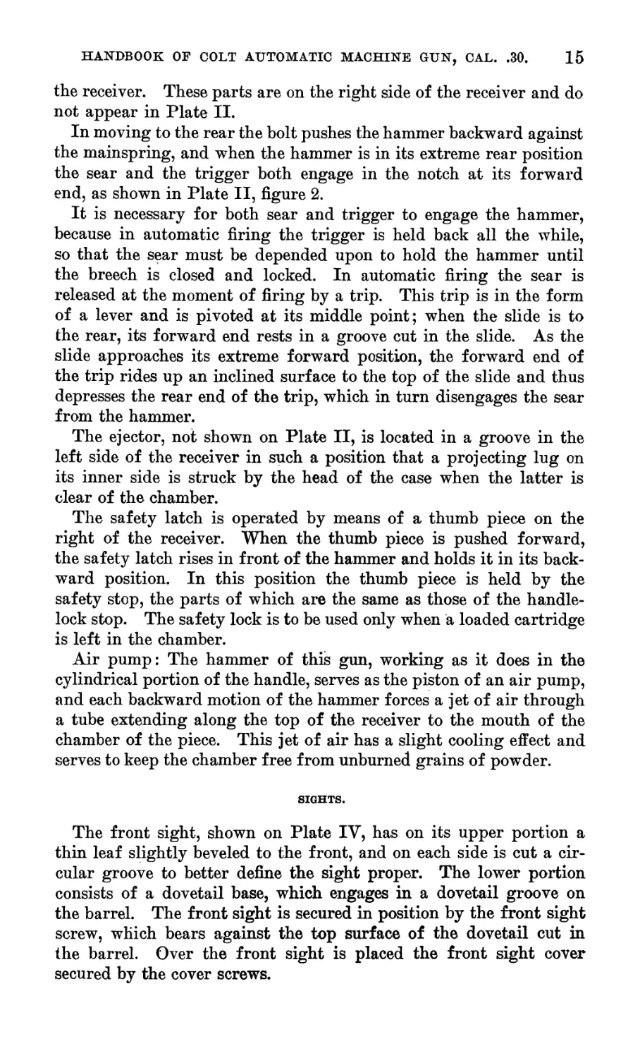
THE MOUNT.
The mount consists of two principal parts—the saddle, with its
toothed arc, and the yoke.
The saddle, in which the gun rests, is pivoted to the yoke by
means of the axis bolt, so as to swing in a vertical plane.
The gun is held in place on the saddle by the gun pin. wThich is
inserted with its handle vertical. In any other position of the
handle, the gun pin is held secure by the gun-pin lock screw, not
shown in figure.
Changes of elevation are made by means of the worm gear, which
engages in the teeth of the arc and is operated by means of the
handwheel. The gun may be secured at any desired elevation by
the arc clamp.
The lower part of the yoke is in the form of a spindle, and fits
in the socket of the tripod, to which it is secured by means of the
spindle washer and the spindle-washer bolt. This washer and bolt
have been pronounced unsatisfactory for service, and in future
constructions will be replaced by a spring catch in the socket of
the tripod engaging in a groove in the spindle of the yoke.
The gun is ordinarily left free to move in a horizontal plane, the
direction being controlled by the firer using the shoulder rest, but
2017—17---------2
18 HANDBOOK OF COLT AUTOMATIC MACHINE GUN, CAL. .30.
it may be clamped in any desired position by means of the mount
clamp (part of tripod).
The shoulder rest is secured to the saddle by m£ans of the shoulder-
rest binder screw.
THE TRIPOD.
The tripod consists of a socket, to which are hinged three legs
made of steel tubing. The two front legs are interchangeable and
somewhat shorter than the rear leg. All three are provided with
brass shoes to prevent their sinking into the ground during firing.
A seat or saddle is attached to the rear leg by means of the saddle
bracket, and may be clamped in any desired position by means of
the saddle-bracket clamp. The rear leg also has attached to it the
spare-parts case described below.
The tripod leg-fastening clip shown on Plate X attached to the
rear leg of the tripod is used to secure the leg in its correct position
when in pack.
DISMOUNTING AND ASSEMBLING THE GUN.
DISMOUNTING.
The gun should not be assembled* or disassembled except under the
direct supervision of an officer or a competent noncommissioned
officer.
Metal parts should not be struck directly with a hammer. If
necessary to strike any parts of the gun, interpose a buffer of wood
or copper between the parts struck and the hammer.
First.—Take hold of the gas-lever pin and throw the gas lever
rearward until it strikes the bottom plate. Then release the gas
lever, when it will fly forward to its original position. This move-
ment cocks the hammer so that it can be removed with the handle.
Second.—On the right-hand side of the gun$ forward of the trigger,
is the handle lock, which is a pin with a small projecting lever resting
in a horizontal position. Turn this lever upward and backward as
far as possible. Withdraw the handle lock out to the right. This
releases the handle, which can then be moved rearward. The handle
contains the mainspring, hammer, sear, sear spring, trigger, and
trigger spring. To remove the hammer and mainspring from the
handle, pull back the trigger, release the sear by pulling the nose
down, when the hammer and mainspring will fly out, as the sear
holds them in place.
Third.—To remove the bolt throw the gas lever rearward as far as
possible, and while holding it in that position insert the small end of
the handle lock in the hole on the right-hand side of the gun, pushing
the handle lock in as far as it will go. This removes the bolt pin
from the bolt. Withdraw the handle lock, but leave the bolt pin in
the’position in which it now is, i. e., projecting from the left side.
The bolt is now free to be removed from the rear of the gun.
TRIPOD AND MOUNT.
PLATE V,
HANDBOOK OF COLT AUTOMATIC MACHINE GUN, CAL. .30. 19
Fourth,—The extractor and firing pin can be removed from the
bolt by pushing out the small pins that hold them in place.
ASSEMBLING.
First,—Insert the bolt and push forward as far as it will go.
Second,—Place hand on gas lever holding it up against bottom
plate.
Third,—Push in bolt pin from left-hand side as far as it will go.
Fourth,—Then release the gas lever.
Fifth.—Replace handle, locking it in position with handle lock.
OPERATING THE GUN.
PREPARING THE GUN FOR FIRING.
(1) Remove the gun and tripod from pack.
(2) Place the gun in position on the erected tripod and secure it
with the gun pin.
(3) Raise the rear-sight leaf.
(4) Place the ammunition box on the ribs on left side of the mount,
in position for firing.
FIRING.
(1) Set the rear sight for range and deflection.
(2) Load by inserting the brass tip of the cartridge belt through
the cartridge-shaped opening on the left of the gim and drawing it
out on the other side of the gun as far as it will go. This brings the
first cartridge on top of the feed wheel. Let go of the belt.
(%) Swing the gas lever downward and to the rear until it strikes
the bottom plate of the receiver. When released the lever resumes its
normal position.
(4) If desired to hold the gun ready for firing push the safety
latch from “fire” to “safe”; otherwise fire the piece by pulling the
trigger to the rear. If the trigger is held, firing will continue until
the supply in cartridge belt is exhausted. Releasing the trigger stops
the fire at any time.
PREPARING THE GUN FOR PACKING.
(1) Remove the cartridge belt from gun if partially fired. This
can be accomplished by pushing the knurled head on the feed throw-
off screw forward and then drawing the belt out to the left.
(2) Operate the lever once by hand, to eject the loaded cartridge
that remains in the chamber.
(3) Remove the ammunition box.
(4) Lower the rear-sight leaf.
(5) Remove the gun from tripod.
CLEANING AND CARE OF THE GUN.
In order that the gun may work smoothly it is necessary that it be
thoroughly cleaned and oiled after firing. All tracing of fouling
20 HANDBOOK OF COLT AUTOMATIC MACHINE GUN, CAL. .30.
from the powder gases should be removed from those parts exposed to
them. This is especially true of an automatic gun of this type.
Warm water, with bicarbonate of soda in solution, will aid consider-
ably in removing the fouling. The small pieces of brass, due to the
shearing of the cartridge cases, should be carefully removed from the
mechanism.
It has been found that a deposit of metallic fouling is left in the
bore of the gun when ball cartridges, caliber .30, model of 1906, of
earlier manufacture, are used, and a solution for the removal of
metallic fouling has therefore been issued by the Ordnance Depart-
ment to all post ordnance officers for reissue to organizations in ac-
cordance with the following table of annual allowances:
For a machine-gun company or troop (4 guns) : Ounces.
Ammonium persulphate_____________________________________________ 30
Ammonium carbonate_______________________________________________ 30
Ammonia, 28 per cent_____________________________________________120
One ounce of ammonium persulphate, 200 grains ammonium car-
bonate, 6 ounces ammonia (28 per cent), and 4 ounces water will
make a sufficient quantity of clean 20 guns. If no scales are available
for weighing the ingredients they may be measured, and the equiva-
lents are as follows:
1 ounce of ammopium persulphate equals two medium heaping spoonfuls.
200 grains ammonium carbonate equals one medium heaping spoonful.
6 ounces ammonia, 28 per cent pure, equals three-eights of a pint.
4 ounces water equals one-fourth of a pint.
The spoon referred to above is the spoon issued by the Ordance
Department for the mess outfit.
The solution is made as follows :
The carbonate and persulphate should first be pulverized and
mixed together and the ammonia and water added, after which the
mixture should be thoroughly stirred. The solution should stand
for half an hour before using. The bore of the gun should be plugged
with a cork or wooden plug at the breech end and just below the
metallic fouling. The bore should then be filled with the solution
and the muzzle corked or plugged. The solution should remain in
the bore for about two hours, or long enough to cut the metallic
fouling, after which it should be removed and canton flannel or
other soft material run back and forth through the bore to remove
the residue. Great care must be taken to remove the solution from
all metallic parts, as it may start rusting in a very short time. Spe-
cial care should be used in removing it from the breech mechanism.
The solution may be used several times, but after it has been once
used it should be placed in a bottle and not mixed with any unused
solution. This solvent is expensive and should be used economically.
If the gun is not to be used for some time, it should be thoroughly
cleaned and all the moving parts given a thin coat of cosmic. This
HANDBOOK OF COLT AUTOMATIC MACHINE GUN, CAL. .30. 21
can be best accomplished by warming the latter and applying with
a brush. Before attempting to fire the gun, all this cosmic should Ъе
removed. The moving parts of the mechanism should be lightly
oiled before using. One wiping rod with three joints is furnished
each gun.
If gas escapes at the base of the cartridge it will probably enter
the well of the bolt through the striker hole. In this case the bolt
mechanism must be dismounted and the parts and well of the bolt
thoroughly cleaned.
Before assembling the bolt mechanism all bright parts, except
springs, should be lightly oiled.
Many of the parts can generally be cleaned with dry rags. All
parts, after cleaning, should be wiped with an oiled rag.
The best method of applying oil is to rub with a piece of cotton
cloth, upon which a few drops of oil have been placed, thereby
avoiding the use of an unnecessary amount of oil. This method will,
even in the absence of the oiler, serve for the working parts, which
should be kept continually oiled.
Any part that may appear to move hard can generally be freed by
the use of a little oil.
Sperm oil only shall be used for lubricating metallic bearing and
contact surfaces.
POSSIBLE TROUBLE AND THEIR REMEDIES.
With proper care and treatment, this automatic machine gun will
cause but little trouble. Before firing, all traces of grease or cosmic
should be carefully removed from the working parts, and a belt of
cartridges (preferably dummies) should be placed in the gun and
the lever operated by hand two or three times, as in loading. If
these cartridges enter freely and are properly ejected, it will indicate
at once that the mechanism has been properly reassembled and is in
proper working order.
~With the gun hot from rapid firing, a cartridge should not Ъе
allowed to remain in the chamber longer than six or seven seconds,
as it may Ъе discharged Ъу the heat. In case it is not possible, from
any cause, to withdraw the cartridge within this time, and the lever
is in its normal position, no harm will be done; but if the lever is
partially retracted the bolt is then withdrawn and a “blow back’*
may occur. In either event, keep away from in front of the muzzle
until satisfied that the danger from the explosion of the cartridge Ъу
heat is passed.
Should a misfire occur, the unexploded cartridge should be thrown
out immediately by swinging the lever down and to the rear by
hand, as in loading; this will eject the unexploded cartridge and
reload the piece, ready for continued firing. Before doing so, a
22 HANDBOOK OF COLT AUTOMATIC MACHINE GUN, CAL. .30.
slight pause should be made in order to make sure that it is a misfire
and not a hangfire.
Should a stoppage of the gun occur from any cause, whether on
account of the jamming of a cartridge, misfire, or breakage of a part
of the gun, the lever should be operated once by hand before any
other effort is made to free the mechanism.
If the stoppage occurs when the lever is partially retracted, push
it backward until it strikes the bottom plate. Never push it forward.
In case the lever does not go forward to its normal position after
striking the bottom plate, the mechanism is not freed, and the car-
tridge belt should be at once withdrawn. Should this not free the
mechanism, an examination must be made for breakages.
An infrequent case of jamming is when an empty shell is not
ejected, so that a live cartridge may jam up against the shell in the
chamber or in the receiver. Should the empty shell be in the cham-
ber, draw’ back the lever until it strikes the bottom plate, which will
let the live cartridge and carrier descend into the bottom position,
insert the w’iping rod (the wiping rod should be kept screwed to-
gether 'within,'easy reach), and force out the shell into the opening in
rear of the chamber, still retaining control of the shell by the wiping
rod. Now’ grip the shell, remove the wiping rod, and withdraw the
shell. The lever is*now' free to resume its normal position. Should
the empty shell be jammed in the receiver, insert the wiping rod in
shell. The lever is now free to resume its normal position. Should
the shell, and remove it. After a jamming of this character the ex-
tractor should be examined. If this is broken or chipped, or the
spring does not work well, replace it by a new one.
For purposes of instruction it will be found unnecessary to fire
more than a few rounds at a time at full speed, and a large number
of rounds should not be fired continuously, as the erosion of the
bore is many times greater when the barrel is hot than when it is cool.
ACCURACY OF FIRE.
In target practice it will be found that when a number of shots are
fired, one shot at a time, with a pause between shots, the center of
impact is lower than when the shots are fired rapidly, using the auto-
matic action of the gun.
At 200 yards this difference amounts to about 12 inches.
When the gun is fired from the tripod, the first few shots tend to
cause the trail to settle into the ground, thus increasing the elevation
and causing the shots to go high.
In heavy, compact soil this settling is only slight and ceases after
the first few rounds, but in light, sandy soil it continues sometime-
until 30 or more shells have been fired. It is important, therefore,
HANDBOOK OF COLT AUTOMATIC MACHINE GUN, CAL. .30. 23
in order to secure accuracy, that shots should be fired in groups of
10 or 20, and that the elevation be verified from time to time.
The service ammunition belt, holding 120 cartridges, is intended
for use in actual service only. For target practice two service belts,
holding 50 cartridges each, are issued with each gun. These service
belts are designated as long and short belts, and the use of the short
belt in target practice is necessary to avoid undue heating of the gun,
which would result in rapid deterioration of the barrel.
AMMUNITION.
The ammunition for this gun is the same as that provided- for the
United States rifle, caliber .30, model of 1903. It is fed into the gun
by means of cartridge belts holding 120 cartridges each. The car-
tridges are inserted in the belts by means of the belt-loading machine.
CARTRIDGE BELT.
With each gun are provided 46 cartridge belts made of canvas, by
means of which the cartridges are fed into the gun. Each belt is
designed to hold 120 cartridges, and two are placed in each ammu-
nition box so as to feed freely into the gun, with the end of the belt
having a brass tip on top.
THE AMMUNITION BOX.
The ammunition box is designed to hold two loaded cartridge belts
(240 cartridges) and is made of ash. It is 13 inches long, 7^ inches
deep, and 4| inches wide, exterior dimensions; the ends and sides
are dovetailed together, and the bottom and fixed portion of the top
are secured to the former by screws. The lid is secured to the fixed
portion of the top by a hinge and held in its closed position by a lid
catch. The latter is a brass, S-shaped catch hook secured in a brass
catchplate by a pin. This plate is attached to the lid by three rivets
and a brass reinforce plate. On the interior is a spiral spring which
supports one end of the catch hook and keeps the opposite end en-
gaged in the brass catch socket, which is screwed to the body of the
chest. By pressing down on the catch hook the lid can be unfastened.
The lid is provided with a handle of brass wire attached to it by
means of two brass handle sockets.
One end of the box is sloped to facilitate the egress of the ammu-
nition belt, the end piece being thickened on the outside for a distance
of about 3 inches from the top to present a surface parallel to the
other end. About % inch back from the vertical edges of the sloping
end are cut the two narrow grooves which fit over correspondingly
spaced flanged ribs of the saddle of the mount, supporting the box
and belt in position for firing on the left side of the mount.
The interior of the box is given a coat of linseed oil and its exterior
is painted olive drab.
24 HANDBOOK OF COLT AUTOMATIC MACHINE GUN, CAL. .30.
THE BELT-LOADING MACHINE.
SERIAL LIST OF COMPONENT PARTS.
[Numbers before components refer to numbers on Plate VI.]
1. Frame.
2. Frame cap.
3. Frame-capscrews (4).
4. Magazine.
5. Magazine screws (2).
6. Magazine dowel pins (2).
7. Cartridge guide.
8. Cartridge-guide key.
9. Cam.
10. Crank.
11. Crankshaft.
12. Crank handle.
13. Crank-handle pin.
14. Crank-handle paw’l.
15. Crank-handle pawl spring.
16. Crank-handle pawl pin.
17. Crank screw.
18. Upper feed wheel.
19. Upper feed-wheel screw.
20. Upper feed-wheel arm.
21. Upper-feed wheel arm screw.
22. Lower feed wheel.
23. Lower feed-wheel screw.
24. Lower feed-wheel spring.
25. Lower feed-wheel spring screw.
26. Tension spring.
27. Tension-spring screw.
28. Tension-spring hook.
29. Tension-spring hook screw.
30. Slide.
31. Slide connection.
32. Slide-connection pin.
33. Slide-connection screw.
34. Feed lever.
35. Feed-lever spring.
36. Feed-lever spring screw.
37. Carrier.
38. Carrier pin.
39. Carrier spring.
40. Carrier-spring pin.
41. Carrier-stop pins (2).
42. Needles (2).
43. Needle screws (2).
44. Needle-screw washers (2).
45. Needlebars (2).
46. Needle-bar screws (2).
47. Needle-bar slide.
48. Needle-bar lever.
49. Needle-bar lever pin.
50. Needle-bar lever spring.
51. Needle-bar lever spring screw.
52. Needle-bar lever spring dowel pin.
53. Belt guide.
54. Belt-guide screws (2).
55. Belt-guide dowel pins (2).
56. Belt-guide cover.
57. Belt-guide cover screw.
58. Cartridge stop.
59. Cartridge-stop spring.
60. Cartridge-stop spring screw.
ALPHABETICAL LIST OF COMPONENT PARTS.
[The numbers after the components refer to the numbers on Plate VI.]
Belt guide (53).
Belt-guide cover (56).
Belt-guide cover screw (57).
Belt-guide dowel pins (two) (55).
Belt-guide screws (two) (54).
Cam (9).
Carrier (37).
Carrier pin (38).
Carrier spring (39).
Carrier-spring pin (40).
Carrier-stop pins (two) (41).
Cartridge guide (7).
Cartridge guide key (8).
Cartridge stop (58).
Cartridge-stop spring (59).
Cartridge-stop spring screw (60).
Crank (10).
Crank handle (12).
Crank-handle pin (13).
Crank-handle pawl (14).
Crank-handle pawl pin (16).
Crank-handle pawl spring (15).
Crank screw (17).
Crankshaft (11).
Feed lever (34).
Feed-lever spring (35).
Feed-lever spring screw (36).
Frame (1).
Frame cap (2).
Frame-capscrews (four) (3).
Lower feed wheel (22).
Lowrer feed-wheel screw (23).
PLATE VI.
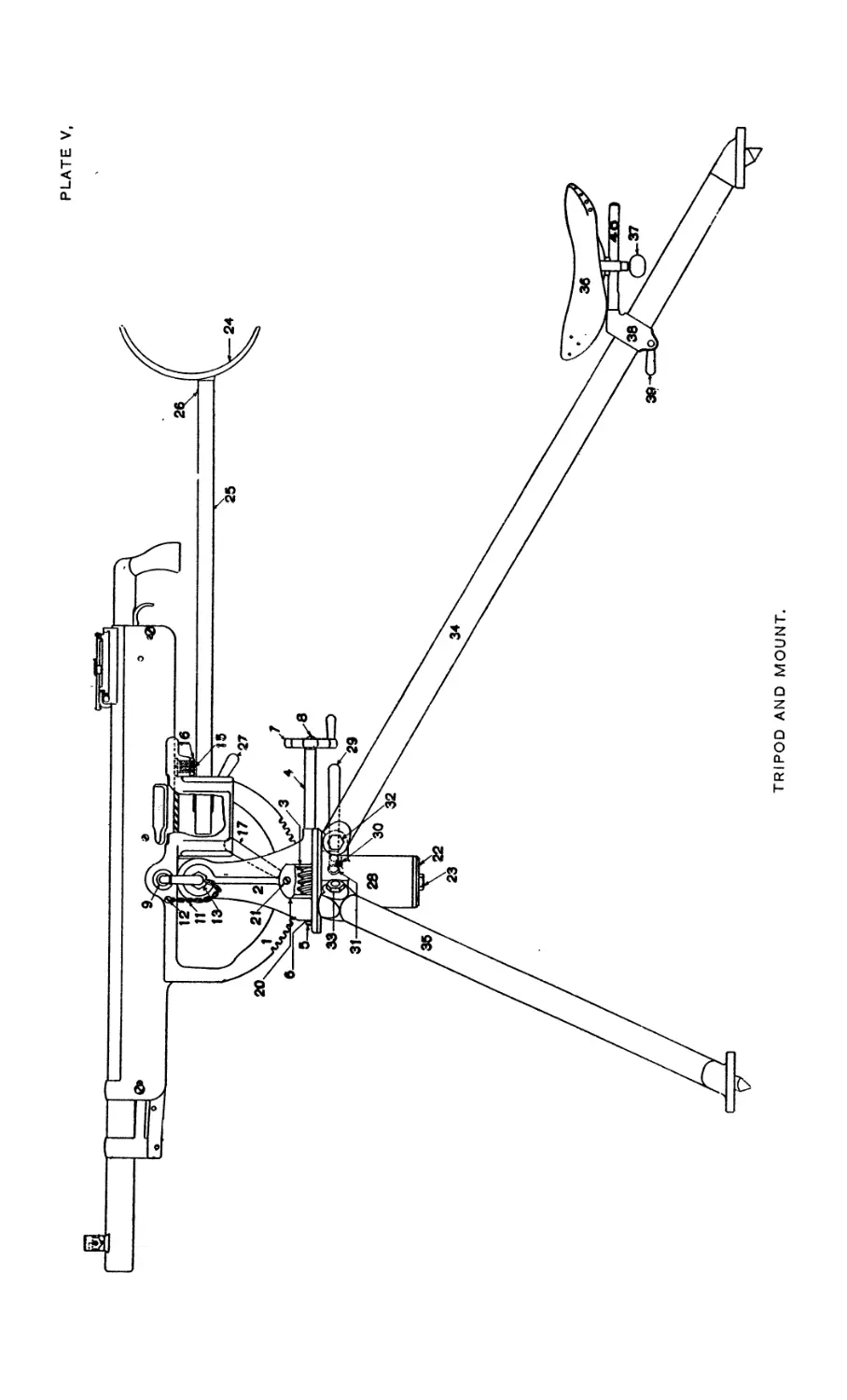
COMPONENT PARTS OF BELT LOADING MACHINE.
HANDBOOK OF COLT AUTOMATIC MACHINE GUN, CAL. .30. 25
Lower feed-wheel spring (24).
Lower feed-wheel spring screw (25).
Magazine (4).
Magazine dowel pins (two) (6)
Magazine screw (two) (5).
Needles (two) (42).
Needle bars (two) (45).
Needle-bar lever (48).
Needle-bar lever pin (49).
Needle-bar lever spring (50).
Needle-bar lever spring screw (51).
Needle-bar lever dowel pin (52).
Needle-bar screws (two) (46).
Needle-bar slide (47).
Needle screws (two) (43).
Needle-screw washers (two) (44).
Slide (30).
Slide connection (31).
Slide-connection pin (32).
Slide-connection screw (33).
Tension spring (26).
Tension-spring hook (28).
Tension-spring hook screw (29).
Tension-spring screw (27).
Upper feed wheel (18).
Upper feed-wheel arm (20).
Upper feed-wheel arm screw (21).
Upper feed-wheel screw (19).
DESCRIPTION OF THE BELT-LOADING MACHINE.
This machine is for the rapid charging of the canvas belts with
ammunition, and is intended to be fastened to a table or bench while
in use. One machine complete is issued with each gun. Plate VI
shows the component parts, and together with the actual machine will
enable the detailed description that follows to be readily understood.
The frame is of cast iron and serves as a support to all the other
parts.
The magazine, through which the cartridges are fed from the
cartridge guide, is of brass and is fastened to the top of the machine
by the two magazine screws.
The crank is fastened to the crank shaft by the crank screw. The
crank shaft is secured in its bearing in the frame by the frame cap
and the four frame-cap screws. Within the crank is the crank-
handle pawl, which engages the crank shaft when the crank is turned
forward (to the right), but allows the crank to be turned backward
without operating the machine.
On the end of the crank shaft opposite the crank is the cam which
operates the feed lever and the needle-bar lever.
The feed lever engages in the teeth of the lower feed wheel and
causes it to move forward one notch at each revolution of the crank.
The needle-bar lever is an L-shaped piece, one end of which bears
against the cam and the other engages the needle-bar slide.
The two needle bars are fastened to the needle-bar slide by the
needle-bar screws.
The needles are secured to the needle bars by the needle screws and
the needle-screw washers.
The needle-bar lever spring is a broad flat piece of steel which bears
against the rear ends of the two needle bars and serves to keep the
two needles pressed against the cartridge belt.
The belt guide is fastened to the right of the frame by the two
belt-guide screws.
26 HANDBOOK OF COLT AUTOMATIC MACHINE GUN, CAL. .30.
The belt-guide cover is secured to the belt guide by the belt-guide
cover screw, about which it is free to revolve.
The slide is connected to the crank shaft by the slide connection,
which gives it a reciprocating motion and causes it to force the
cartridges into the belt.
The cartridges are carried in front of the slide from the magazine
by the carrier, which is pivoted to the frame by the carrier pin.
The play of the carrier is limited by the two carrier-stop pins. As
the cartridge passes from the magazine it presses down the cartridge
stop, which rises behind the cartridge as soon as it has passed and
steadies the cartridge as it is moved forward under the action of the
slide.
The upper feed wheel is pivoted to the upper feed-wheel arm by
the upper feed-wheel screw. The upper feed wheel is pressed down
upon the cartridge belt by the tension spring, which engages with
the tension-spring hook.
TO FILL A FEED BELT WITH CARTRIDGES.
Fasten the machine to a table or bench and turn the crank to the
right until it is straight down.
Release the tension-spring hook and raise the upper feed wheel as
far as it will go.
Turn the belt-guide cover to the right far enough to admit the belt
into the belt guide and raise the upper needle bar as far as it will go.
Put two cartridges by hand into the two loops of the belt nearest
the end with the brass tip and place the belt in the machine with the
first cartridge resting in the top groove of the lower feed wheel, and
the belt passing out at the back through the belt guide.
Return the belt-guide cover to place over the belt (being careful
to see that the belt is free to pass under it) and lower the needle bar.
Turn the upper feed wheel down upon the belt and secure the
tension spring under the hook.
Fill the feed guide with cartridges by stripping 10 at a time from
the paper boxes in which they are packed.
Turn the crank to the right and the cartridges will be fed into the
belt ready for use in the gun.
Place a feed box ready to receive the filled belt and at such a
height that not more than 2 feet of filled belt will be suspended from
the feed wheels of the machine.
PRECAUTIONS.
Before beginning to use the machine, see that it is well oiled and
that the needles are properly set. The needles should be so placed
as to have their points even (in same vertical line), and about one
one-hundredth of an inch apart.
HANDBOOK OF COLT AUTOMATIC MACHINE GUN, CAL. .30. 27
In case of a miss in charging the belt, stop and open up the machine
and remove the belt. Turn the crank to the right until straight
down, as in starting, and replace belt in machine with the next to
the last cartridge in the top groove of the lower feed wheel. Close
the machine and proceed as before.
THE BELT-LOADING MACHINE BOX.
The belt-loading machine box is designed to hold the belt-loading
machine and is made of ash. It is 13 inches long, 7^ inches deep,
and 4T3g inches wide, exterior dimensions; the ends and sides are
dovetailed together, and the bottom and fixed portion of the top
are secured to the former by screws. The lid is secured to the fixed
portion of the top by a hinge and held in its closed position by a
lid catch similar to that used on the ammunition box. The lid
is provided with a handle of brass wire attached to it by means of
two brass-handle sockets.
The top attachment is a small plate of aluminum alloy containing
a small cup-shaped recess, which fits over a hole in the lid and thus
furnishes necessary additional space for a projecting part of the
leading machine.
The bottom attachment, for a similar purpose, is of the same
material. It is a rectangular plate containing a shallow rectangular
recess and is fastened to the bottom over a similarly shaped hole
therein.
The interior of the box is provided with suitable blocks and com-
partments for receiving the loading machine.
SPARE-PARTS CASE.
This case is a leather pouch used for carrying several small tools
and the spare parts of the gun, tripod, mount, and belt-loading
machine. It is made of russet harness leather fastened by three
securing straps to the long tripod leg and closed by three billets and
straps. Within the case is stitched an inner pocket, having a flap,
which is secured to the inner pocket front by three fasteners.
PART II. PACK HARNESS.
The group of parts of the pack outfit used for leading the animal
and carrying the load with its special holders is called the 66 pack
harness.” It consists of the blinder, halter, bridle, corona, saddle
blanket, aparejo, sobr?jalma, crupper, and aparejo cincha.
These parts are common to all aparejo outfits and may be used
without special frames for packing bundles and boxes.
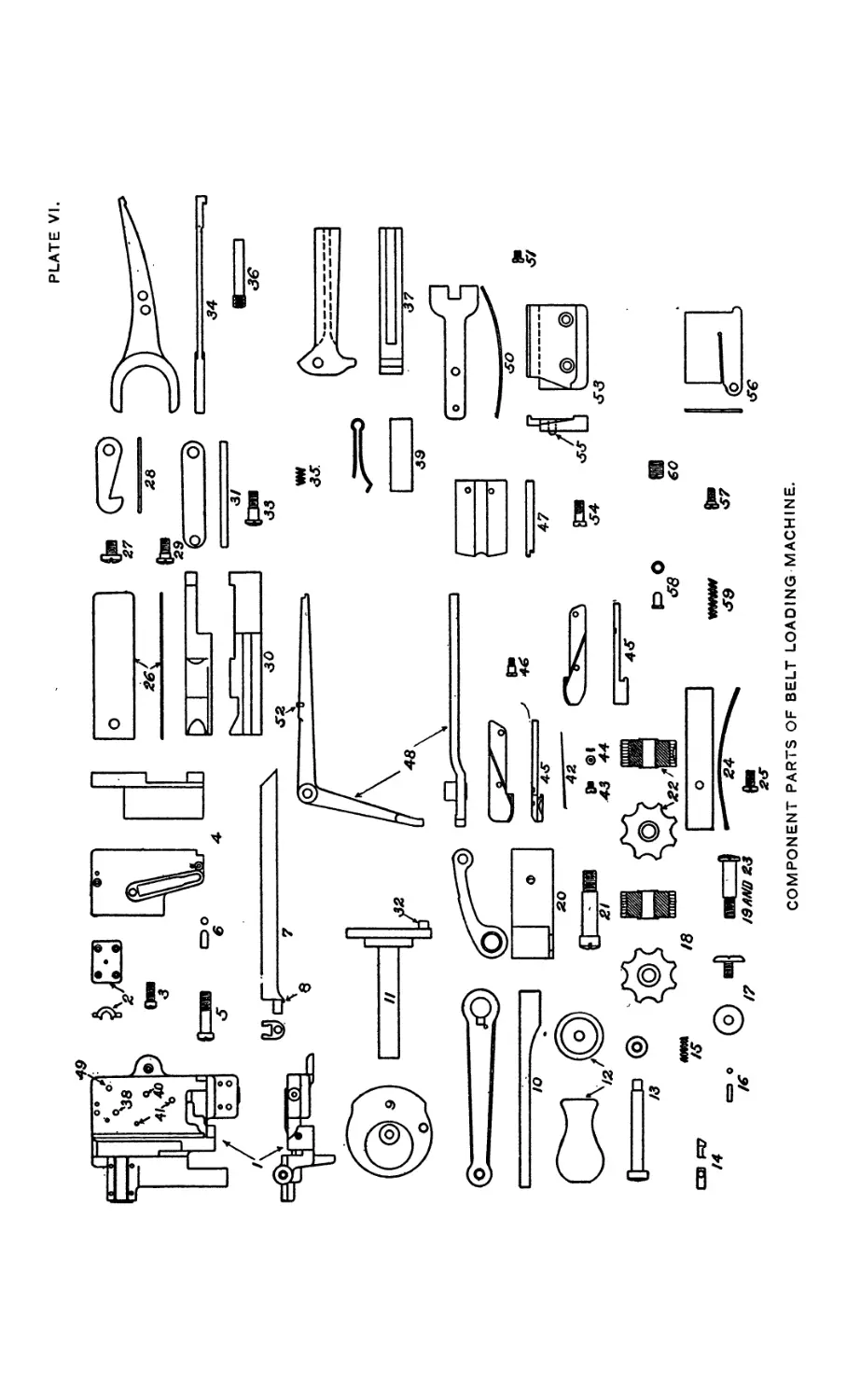
BLINDER, MODEL OF 1916.
A pack mule is ordinarily blinded during harnessing and unhar-
nessing, loading and unloading. The blinder consists of an inner
28 HANDBOOK OF COLT AUTOMATIC MACHINE GUN, CAL. .30.
and outer piece of harness leather stitched together around the outer
edges and joined in the rear by leather thongs, the whole shaped
to fit closely around the animal’s eyes.
HALTER BRIDLE, MODEL OF 1910.
This article is designed to furnish a light, strong head harness
for a mule. When leading the animal on the march the bit and its
straps are removed from the headstall and fastened to any con-
venient place on the pack frame. The two snaps of the lead rein are
then fastened to the floating ring, the body of the rein forming a
loop convenient for holding in the hand.
In riding the animal the lead rein is used in combination with the
bit, headstall, and bit straps as a bridle.
When a mule is picketed to a line the lead rein serves as a halter
strap.
The bit is made of nickle steel to prevent rusting.
CORONA, MODEL OF 1910.
The corona is the first piece of harness placed on the mule’s back.
It is a Saddle pad made of four thicknesses of good quality gray
flannel, protected from sweat by a lining of cotton duck. The corona
is made in three sizes, and each size is stenciled on the underside to
correspond with the size of the aparejo it is intended to accompany.
The width is 26 inches for all sizes. In placing the corona it is laid
well forward on the mule’s back, canvas side down, and then slid to
the rear until its front edge is just behind the point of the withers,
care being taken that the hair lies smooth beneath it.
When manufactured in quantity, 10 per cent are 58-inch, 15 per
cent 60-inch, and 75 per cent 62-inch.
THE SADDLE BLANKET.
The saddle blanket forms additional padding under the aparejo.
It is carried under the aparejo and over the corona.
The blanket is made of pure wool of olive-drab shade with an
olive-brown border of two stripes. The blankets are rectangular,
72 by 84 inches. Each blanket has the letters “ U. S.” and the
bursting shell located in the center.
APAREJO, MODEL OF 1911.
This article consists of an aparejo body and one aparejo frame.
The aparejo body is made of two rectangular pieces of leather (back
and belly pieces) sewed together along the edges and through the
middle, forming two pouches. The edges, the middle seams, and
particularly the ends are reinforced with heavy leather facings.
Handholes for stuffing are left in the belly pieces, and holes and
PLATE VIII.
HANDBOOK OF COLT AUTOMATIC MACHINE GUN, CAL. .30. 29
slits laced with thongs are made in the back pieces so that the frame,
or parts of it, may be inserted, removed, or replaced. The carrier
pieces and front facing have lacing holes for the attachment and
adjustment of the crupper. Two steel chock staples attach the sobre-
jalma and pack frame to the aparejo. The rib sticks are furnished
longer than necessary and should be sawed off to the proper length
after the boot and top sticks are firmly rammed home. The first
three sticks (starting at the front) are of uniform thickness; the
remainder are tapered to give the rear of the aparejo more fexibility
than the front. The sticks are stamped and are intended to be ar-
ranged in a gradually diminishing thickness.
Cloth is tacked to the top stick to prevent the hay from slipping
down.
Note.—Aparejos are issued to the service with ribs in place. They
are furnished in 58, 60, and 62 inch sizes, as follows: 10 per cent 58-
inch, 15 per cent 60-inch, and 75 per cent 62-inch. Should repairs
or alterations make it necessary to rib up, the butt of the fifth rib is
seated in its slot, the overlap at its slot in the top stick is marked and
cut away, and the other ribs are cut to the exact resulting length.
SOBREJALMA, MODEL OF 1910.
This article is a waterproof and wear-reducing covering for the
aparejo. It is made of one thickness of heavy cotton duck, faced
around the edges on the upper side with collar leather. Two leather
reinforces are placed on the upper side to protect the duck from the
wear of the load. Holes are provided through which the chock
staples of the aparejo protrude; chock straps passing through these
chock staples hold the sobrejalma and pack frame on the aparejo.
Supporting caps at both ends of the end facings hold the supporting
sticks in place. Sobrej almas are made in three sizes, and when
manufactured in quantity 10 per cent are 58-inch, 15 per cent 60-inch,
and 75 per cent 62-inch. The size stamped on the sobrejalma is the
size of the aparejo for which it is suited.
CRUPPER, MODEL OF 1912.
The crupper is made of russet collar leather, shaped (and padded
in the middle) to fit the animal. The side pieces extend forward
across the aparejo, and are laced to it in front and held up at rear
by latigo-leather thongs. The depth of the side pieces affords a
broad surface to bear against the animal and also prevents the crup-
per from sagging. The side pieces are reinforced around their edges
with leather and those portions which come in contact with the
animal’s flanks are lined with duck. Cruppers are made in one size
only, 78 inches long.
30 HANDBOOK OF COLT AUTOMATIC MACHINE GUN, CAL. .30.
APAREJO CINCH A, MODEL OF 1910.
The aparejo cincha is 10 inches wide and is made of cotton duck,
folded, and stitched along the middle. Both ends are faced with
leather, and the end to which the cincha strap is fastened carries a
five-sixteenths-inch steel rod in the fold of the lacing-end piece,
while the other end has a curved piece of gas pipe (cincha bar).
Fifteen inches from the strap end of the cincha a leather thong
(finger loop) is attached, which is used to carry the slack of the
cincha strap. The cincha strap is of harness leather and has a ren-
dering ring at one end; this end is attached to the cincha body by a
latigo-leather thong. The metal parts are either of bronze or are
copper plated to prevent rotting of the leather. The cincha is made
in three sizes and when manufactured in quantity 10 per cent are
58-inch, 15 per cent 60-inch, and 75 per cent 62-inch. The size
stamped on the cincha is the size of the aparejo for which it is
designed.
INSTRUCTIONS FOR SETTING UP THE APAREJO.
To rib Unlace the slits and handholes; soak the aparejo in
tepid water for about 15 minutes; drain it and lay flat, back pieces
up; insert the boot stick and the top stick through the slit in rear,
and press them to their places at the boot and the center stitch line,
slotted sides up; insert the numbered set of nine ribs through the
slit in rear in their numerical order and seat them in that order from
collar to rear in the slots of the boot stick and top stick, butts at the
boot; secure the top of each rib as it is seated by inserting the aparejo
key at the front edge below the collar and passing it over to the rib
in place; fasten the key bar to the collar by the thong.
Note.—The aparejo after being set up should under no circum-
stances be allowed to dry in the sun.
To fill or pad.—Turn the aparejo over, belly pieces up; procure
about 6 pounds of long, fine, soft, elastic hay, taking a little at a
time, tease or “ mix ” it carefully; insert it through the handhole and
thus gradually fill the body of the aparejo with a smooth and even
layer, not more than 2 inches thick.
Note.—Other filling may be used in necessity, such as moss, excel-
sior, curled hair, or sea grass; but these substitutes are difficult of
manipulation in alterations necessary to accomodate the rigging to
injuries of the mule. By teasing or “ mixing ” is meant the arrange-
ment of the stalks of the hay so that they will cross one another. The
body of the aparejo is that part which comes in contact with the body
of the mule. As 3 inches of the louver portion of each boot stick and
3 inches of the upper portion of each top stick must not come into
contact with the mule, no filling should be pressed under the boot
PLATE IX
HANDBOOK OF COLT AUTOMATIC MACHINE GUN, CAL. .30. 31
stick or within 3 inches of the center of the stitch line. The body
course tapers, however, so as to overlap the boot stick and saddle bar,
and also tapers toward front and rear.
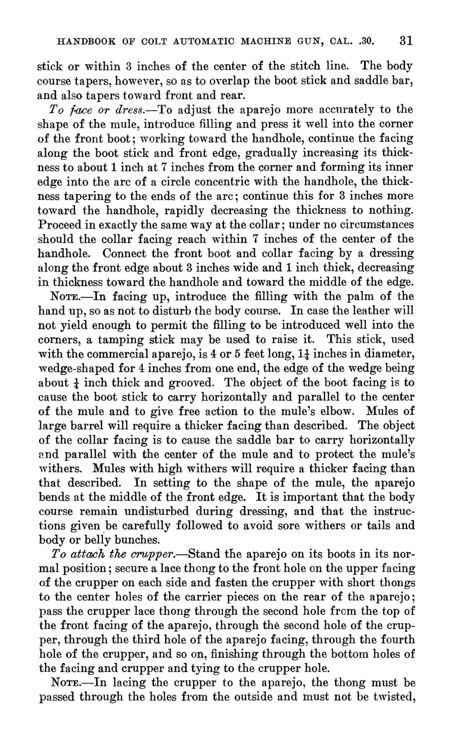
To face or dress.—To adjust the aparejo more accurately to the
shape of the mule, introduce filling and press it well into the corner
of the front boot; working toward the handhole, continue the facing
along the boot stick and front edge, gradually increasing its thick-
ness to about 1 inch at 7 inches from the corner and forming its inner
edge into the arc of a circle concentric with the handhole, the thick-
ness tapering to the ends of the arc; continue this for 3 inches more
toward the handhole, rapidly decreasing the thickness to nothing.
Proceed in exactly the same way at the collar; under no circumstances
should the collar facing reach within 7 inches of the center of the
handhole. Connect the front boot and collar facing by a dressing
along the front edge about 3 inches wide and 1 inch thick, decreasing
in thickness toward the handhole and toward the middle of the edge.
Note.—In facing up, introduce the filling with the palm of the
hand up, so as not to disturb the body course. In case the leather will
not yield enough to permit the filling to be introduced well into the
comers, a tamping stick may be used to raise it. This stick, used
with the commercial aparejo, is 4 or 5 feet long, l.| inches in diameter,
wedge-shaped for 4 inches from one end, the edge of the wedge being
about i inch thick and grooved. The object of the boot facing is to
cause the boot stick to carry horizontally and parallel to the center
of the mule and to give free action to the mule’s elbow. Mules of
large barrel will require a thicker facing than described. The object
of the collar facing is to cause the saddle bar to carry horizontally
and parallel with the center of the mule and to protect the mule’s
withers. Mules with high withers will require a thicker facing than
that described. In setting to the shape of the mule, the aparejo
bends at the middle of the front edge. It is important that the body
course remain undisturbed during dressing, and that the instruc-
tions given be carefully followed to avoid sore withers or tails and
body or belly bunches.
To attach the crupper.—Stand the aparejo on its boots in its nor-
mal position; secure a lace thong to the front hole on the upper facing
of the crupper on each side and fasten the crupper with short thongs
to the center holes of the carrier pieces on the rear of the aparejo;
pass the crupper lace thong through the second hole from the top of
the front facing of the aparejo, through the second hole of the crup-
per, through the third hole of the aparejo facing, through the fourth
hole of the crupper, and so on, finishing through the bottom holes of
the facing and crupper and tying to the crupper hole.
Note.—In lacing the crupper to the aparejo, the thong must be
passed through the holes from the outside and must not be twisted,
32 HANDBOOK OF COLT AUTOMATIC MACHINE GUN, CAL. .30.
the lacing must not cross, and it is important that the tie be made on
the last hole of the crupper instead of the aparejo.
Guayaba, willow, dogwood, hickory, or any other wood combining
the qualities of permanent elasticity and strength may be used to
replace broken ribs. When the set-up aparejo is to be filled, no soak-
ing is necessary; instead, the belly pieces are made pliable by rubbing
with a sponge.
Mules weighing 850 to 900 pounds require a 58-inch aparejo; 1,000
pounds, 60-inch; 1,100 pounds, 62-inch.
When the mule is loaded, the cincha, in travel, should free the
elbow by about 1 inch; more than this will prevent a proper grip on
the belly.
If the boots ride high enough on the body of the mule, or if they
reach under the belly, even though they ride horizontally and paral-
lel to the center of the mule, the aparejo will be likely to turn easily.
This fault encourages injuriously tight cinching.
If one or both boots flare out or turn in toward the mule, cinch
sores, sore tails, or belly bunches are caused.
The width of the collar-arch clearance should be at least 5| inches.
If it is too harrow or too wide, or if the saddle bars slopes downward
toward the front, there will be sores on the withers; if they slope to
the rear, there will be injuries over the loins called “ kidney sores.”
If the lacing of the crupper is drawn too tight at the bottom, the
lower edge of the crupper will rub the buttocks and cause abrasions.
The object to be attained is the uniform distribution of the weight
of a load over that portion of the mule’s body which is anatomically
suited to the carrying of a burden, so that the saddle will ride with
little motion and without friction of the bearing surface on the body.
The contact of the bearing surface of the saddle must be close at all
points. As the mule’s body swells from front to rear, the more or less
cylindrically shaped aparejo, after the body course is laid, must be
modified by facing up so as to provide a concave surface to fit over
the convex surface. But, as the barrel of the properly conformed
mule is nearly cylindrical through the rear half or more of the con-
tact surface, no facing, as a rule, is necessary in the rear part of the
aparejo, although conformation may require it occasionally. The
above instructions were prescribed by H. W. Daly, chief packmaster,
Quartermaster Corps.
CARE OF RUSSET LEATHER.
Leather equipments which have become wet should be dried in the
shade. Wet leather exposed to the direct rays of the sun or to the
heat of a stove or radiator becomes hard and brittle. Only cool or
lukewarm water should Ъе used on leather; the use of hot water is
prohibited.
X Э-LV-ld
PLATE XI.
Btyying Cover.
'SjiweSarie/, Case.<
|МЖ /,Guv T/avverM&del of
t i // 7 /э/г.
/Shoulder ftest.
Cur Case.
Thorns.
dtick-Jaume, _
Mx7e?af/9//.
Sobre/alma,
/9//-
\Co7w?a,
Mode?of.79/0.
'Apery 's C//?c7?a, Model af/9/S
es67S
HANDBOOK OF COLT AUTOMATIC MACHINE GUN, CAL. .30. 33
When russet-leather equipments become soiled in service they
should be cleaned by carefully washing the leather with a sponge
moistened with a heavy lather made of clean water and castile or
Frank Miller’s soap, and then rubbing vigorously with a dry cloth
until the leather is completely dry.
If the leather becomes harsh, dry, and brittle from exposure to
water or other causes, clean as above described, and while the leather
is still slightly moist apply an exceedingly light coat of neat’s-foot
oil by rubbing with a soft cloth moistened (not saturated') with the
oil. If it is found that too much oil has been used, the surplus can
be readily removed by rubbing with a sponge moistened with
naphtha or gasoline. But these oils are not issued for this purpose.
Where a polish is desired, the leather should first be thoroughly
cleaned, and then the leather polish or dressing supplied by the
Ordnance Department should be applied sparingly and thoroughly
rubbed in with a soft, dry cloth. Scars, cuts, or abrasions of the
leather may be improved in appearance, but not obliterated by simi-
lar use of the leather polish.
Russet leather may be cleaned, oiled, and polished as described
above, but it should be noted that if more than a light coat of oil be
given the leather will be greatly darkened and will quickly soil the
clothing. No method of cleaning will restore the original light color
of the leather or remove stains or discolorations.
PART III. THE SPECIAL PACK EQUIPMENT.
This equipment includes the following:
Pack frame, model of 1911.
Ammunition hanger, model of 1912.
Gun hanger, model of 1912.
Tripod hanger, model of 1912.
Gun case.
Tripod hood.
Spare-barrel case.
Broad hatchet head case.
Picket-pin carrier.
Pick-mattock fastening straps.
Shovel-fastening straps.
Picket rope, section.
Picket pin and eye.
Rigging cover.
Thongs.
Plates X to XV, inclusive, show the special pack equipments,
with their loads attached, placed on the pack harness for the first,
second, third, and fourth mules. The loads for the fifth, sixth,
seventh, and eighth mules are similar to these except as shown in
the table of equipment.
2017—17----3
34 HANDBOOK OF COLT AUTOMATIC MACHINE GUN, CAL. .30*
PACK FRAME, MODEL OF 1911.
This article consists of a framework built up of wood and metal
to carry the weight of the load and distribute it uniformly over the
carrying surface of the aparejo. It is arranged to suit the load to
be carried. To the top of the pack frame are attached four bronze
castings, known as superframes, which, when folded up. form a fiat
surface for carrying boxes or packages which have flat sides, or. when
folded down, form a convenient receptacle to hold picket pins,
shovels, picket ropes, or other items of a similar nature. Four steel-
loop clevises with straps are fastened to the top of the pack frame,
furnishing means of lashing articles to the frame. The steel arches,
with the bronze superframes, are interchangeable and may be re-
moved by withdrawal of the steel pins. The sides of the pack frames
are riveted together. The hook hinges are made of forged steel and
are arranged for hanging boxes or hangers on the sides of the pack
frame. Four pack-frame staples are fastened to the brace bar and
are used for holding down side loads.
AMMUNITION HANGER, MODEL OF 1912.
This article consists of a light steel frame for carrying ammuni-
tion boxes. . Hanger eyes are located on the upper part of the rear
frame to facilitate attaching the hanger to the spack frame. The
straps on top which lash the boxes in place are provided with quick-
release devices. Straps with quick-release devices also are provided
to fasten the hanger to the pack frame.
GUN HANGER, MODEL OF 1912.
This article consists of a steel frame for carrying the gun case.
Hanger eyes on the rear of the gun hanger frame attach the hanger
to the pack frame. Straps with quick-release devices secure the
hanger to the pack-frame staples.
TRIPOD HANGER, MODEL OF 1912.
This article consists of a steel frame for carrying the tripod.
Hanger eyes riveted to the hanger frame attach the hanger to the
hook hinges on the pack frame. On the hanger frame are riveted
the head end support and leg support which accommodate, respec-
tively, the upper portion and the legs of the tripod. Straps with
quick-release devices secure the hanger to the pack-frame staples.
GUN CASE.
This case is made of sole leather, and its purpose is to protect the
gun from damage in transportation and from the weather. It is
arranged in such a way that the gun may be removed with great ease
HANDBOOK OF COLT AUTOMATIC MACHINE GUN, CAL. .30. 35
and rapidity. Two gun-case stops are riveted to the bottom piece
to locate the case on the hanger and brass guards on the outside of
the case prevent the leather from coming in contact with the metal
gun hanger.
The arm rest is secured to the gun case. It is located in the arm-
rest body piece attached to the body. A strap secures the arm rest
in place.
tripod HOOD.
This hood is used to protect the head of the tripod or mount in
pack. It is made of russet bag leather and is closed by means of
two straps and buckles. A gathering strap held by six loops is
located at the top of the hood.
SPARE BARREL CASE.
This case is made of cotton duck and is closed by wrapping with a
thong. Two fastening straps riveted to the case secure it to the gun
hanger.
BROAD-HATCHET HEAD CASE.
This case, as its name implies, is designed to protect the head of the
broad hatchet and to form a convenient means of carrying that tool.
A strap with a ring is riveted to the flap of the case to form a con-
venient means of lashing the broad hatchet to some convenient part
of the pack in transportation.
picket-pin carrier.
This carrier is made of cotton duck and is designed to afford means
of carrying the picket pin and eye in pack. End pieces of collar
leather are stitched to each end and have fastened to them straps for
securing the carrier to the pack frame. A flap and buckle hold the
pin in its carrier.
PICK MATTOCK FASTENING STRAPS AND SHOVEL FASTENING STRAPS.
Two straps 25.25 inches long are provided for securing the pick
mattock to the pack frame, and two.of the same kind are provided for
securing the shovel to the frame.
RIGGING COVER.
The rigging cover, made of olive-drab duck, is 43 inches wide and
long enough to cover the eight packs of two sections when in park.
36 HANDBOOK OF COLT AUTOMATIC MACHINE GUN, CAL. .30.
PICKET PIN AND EYE.
The picket pin and eye are made of steel. One picket pin and eye
is furnished each section.
PICKET-ROPE SECTION.
This article consists of a 1-inch diameter manila rope, 25 feet long,
with a loop spliced on each end. It is designed to be stretched along
the ground and fastened at the ends with pins. The animals can
then be fastened by means of their halter-bridle reins to this rope in
the usual way. Three picket rope sections are provided for each
company or troop. Two sections of rope can be fastened together
by means of the loops and a pin driven at each end. If it is necessary
to use the sections separately, a shovel or pick mattock could be
used as a “ dead man.”
PART IV. PIONEER TOOLS.
Broad hatchet-------------------------------------------------------------- 2
Pick mattock--------------------------------------------------------------- 2
Short-handled shovel------------------------------------------------------- 6
Rule, 2-foot____________________________________________.---------------- 1
These toolg are commercial articles. They are carried as pre-
scribed on Plates XII and XIII, and in the list of total equipment.
PLATE XV.
/Ammunition ffanaer Л/fafe/
i a//9/2.
Z&c/'titivme,
MteteZ af/9//.-
Mrfe/af/9/2
-tibtine/a/ma,
frfodeZ af/9/0.
Р/с^-Р/т? tiam
men
'oam/o С/пс/га,
fate/ of /9/0-
у/4е).
HANDBOOK OF COLT AUTOMATIC MACHINE GUN, CAL. .30. 37
PART V. EQUIPMENT OF ONE MACHINE-GUN COMPANY OR
TROOP.
The following table sets forth the total equipment of one machine-
gun company or troop armed with the Colt automatic machine gun,
caliber .30. It shows, in general, where each article should be car-
ried, but the commander may use his discretion as to the disposition
of articles for which no particular fitting or receptacle is provided.
In making requisitions for any of these parts the names used
should be those used in this table, or on the plates, or in the descrip-
tive matter of this handbook. If an article is wanted which is not
shown as a whole but shown as made up of component parts, these
component parts should be stated.
Statement of total equipment of one Colt automatic machine-gun company or troop.
co
oo
Name of article. Weight of each. First section mules. Second section mules. Thini section mules. Fourth section mules. Total. Property classi fication.
1 2 3 4 5 6 7 8 9 10 11 12 13 14 15 16 Class. Section.
The gun and tripods with am- munition and accompany- ing parts include: Gun 40 15.4 4.25 14 5 2.5 5 6.06 57 .75 1 1 1 1 4 22,080 rds. 92 4 4 4 4 4-set. 4 4 10 16 16 16 16 16 16 16 16 4 4 24 4 4 4 2 IV V IV IV IX IV IV 1 1 1 1 1 1
Ammunition, 240 rounds in box 1,920 8 1,680 7 1 1 1,920 8 1,920 8 1,680 7 1 1 1,920 8 1,920 8 1,680 7 1 1 1,920 8 1,920 8 1.680 7 1 1 1,920 8
Ammunition box 1
Belt-loading machine... Belt-loading machine box1..
Shoulder rest.. 1 1 l-set. 1 1 i 1 l-set. 1 1 1 1 l-set. 1 1 1 1 l-set. 1 1
Spare barrel...
Spare-parts case with contents1
Tripod and mount with seat Tripod leg fastening clip... The packs for one company or troop: The pack harness— Blinder
Halter bridle, model of 19102 4.33 6.5 5 47.09 7 4.84 5.55 20.30 8.25 10.67 11 5.5 .5 .92 .5 1 1 1 1 1 1 1 1 1 1 1 1 1 1 1 1 1 1 1 1 1 1 1 1 1 1 1 1 1 1 1 1 1 1 1 1 1 1 1 1 1 1 1 1 1 1 1 1 1 1 1 1 1 1 1 1 1 1 1 1 1 1 1 1 Й 1 1 1 1 1 1 1 1 1 1 1 1 1 1 1 1 1 1 1 1 1 1 1 1 1 1 1 1 1 1 1 1 1 1 1 1 1 1 1 1 1 1 1 1 1 1 1 1 1 1 1 1 1 1 1 1 1 1 1 1 1 1 1 1 1 1 1 1 1 1 1 1
Corona, model of 1910... Saddle blanket
Aparejo (including hay, 6 pounds)3
Sobrejalma, model of 1910
Aparejo cinch a
Crupper
The special pack equipment: Pack frame, model of 1911 *. Gun hanger, model of 1912 \ Tripod hanger, model of 1912 «
Ammunition hanger, mod- el of 19127 2 2 2 2 2 2 2 2 2 2 2 2
Gun case 1 1 1 1 1 1 1 1 1 i i 1
Tripod hood
Spare-barrel case
Broad hatchet-head case.. i i
HANDBOOK OF COLT AUTOMATIC MACHINE GUN.
Picket-pin carrier.......
Pick-mattock fastening
strap....................
Shovel fastening strap...
Picket rope section......
Picket pin and eye.......
Rigging cover............
Thongs...................
The pioneer tools:
Broad hatchet.............
Pick mattock.............
Short-handled shovel.....
Total weights........
.67
.10
.10
7
12. 38
16
.05
3
7
5
2 ......
2 4
1
1 .................
6 6 6
1 ........
1 ........
1 2
255 296 296
1 Contents included in tools and accessories and
spare parts listed on p. 40.
2 A halter bridle includes either 1 leather rein or
1 rope rein. Eight leather-rein and eight rope-rein
bridles are issued to each company or troop.
з The hay is not furnished with the aparejo.
1 aparajo consists of—
1 aparejo body.
2 thongs A by 64 inches.
2 thongs Л by 20 inches.
2 thongs Л by 16 inches.
2 thongs by 14 inches.
1 aparejo frame, consisting of—
1 aparejo top-stick body, right.
1 aparejo top-stick body, left.
1 aparejo boot-stick body, right.
1 aparejo boot-stick body, left.
2 aparejo keys.
2 aparejo top plates.
2 aparejo boot plates.
2 sets of aparejo ribs (10 to the set).
41 pack frame consists of—
4 pack-frame top straps.
1 pack-frame body, consisting of—
2 pack-frame sides.
2 arches.
4 superframes.
4 strap-loop clevises.
4 pack-frame pins.
4 split pins.
1
6
293
239 280 286
255 296 296
51 gun hanger consists of—
1 gim-hanger body, consisting of—
1 gun-hanger frame.
2 corner braces.
1 rear brace.
1 rear-brace pad.
2 hanger eyes (right and left).
61-inch strap fasteners.
61 inch by 0.5-inch strap loops.
2 gun-case straps.
2 holding-down straps.
2 holding-down clips.
2 1 inch by 0.5-inch strap loops.
61 tripod hanger consists of—
1 tripod-hanger body, consisting of—
1 hanger frame. ‘
1 rear support.
2 hanger eyes (right and left).
1 leg support.
1 leg-support brace.
1 clamp.
2 clamp hooks.
2 corner braces.
1 clamp loop (1 roller).
2 holding-down straps.
2 1 inch by 0.5-inch strap loops.
2 holding-down clips.
1 head strap.
1 clamp loop (2 rollers).
4
4
12
4
4
2
96
2
2
6
71 ammunition hanger consists of—
1 ammunition-hanger body, consisting of—
1 rear brace.
2 corner braces (right and left).
2 hanger eyes (right and left).
2 side braces (right and left).
1 support brace.
1 rear frame.
1 bottom frame.
2 supports.
1 support-brace pad.
2 2-inch strap fasteners.
1 2 inch by 1.25-inch strap loop.
1 2-inch brass roller.
1 5-sided strap loop.
4 1-inch strap fasteners.
4 1 inch by 0.5-inch strap loops.
1 ammunition strap, clasp billet with
quick-release device.
1 ammunition strap, buckle billet.
2 1 inch by ().5-inch strap loops.
2 holding-down straps.
2 holding-down clips.
1 ammunition billet.
HANDBOOK OF COLT AUTOMATIC MACHINE GUN, CAT.. .30.
CO
О
40 HANDBOOK OF COLT AUTOMATIC MACHINE GUN, CAL. .30.
statement of total equipment of one Colt automatic machine-gun company or
troop—Continued.
Name.
Num-
ber.
Where carried.
Property classi'
neat ion.
Class. Section.
TOOLS AND ACCESSORIES FURNISHED
EACH 4 GUNS.
Ammunition boxes, with 2 cartridge belts each..
Belt-loading machine box, containing 1 belt-load-
ing machine.
Spare-parts case, containing 1 oil can, 2 screw
dri ers, 1 wiping rod in 3 joints, 1 operating
hanob, 3 drifts, 2—0.05 wrenches, and small
parts listed in next table.
Cartridge belts, 120 cartridges.............
TOOLS AND ACCESSORIES FOR PACK
OUTFIT.
Broad hatchet...............................
Pick mattock................................
Picket pin and picket-pin eye...............
Picket-rope section.........................
Rigging cover...............................
Rule, boxwood...............................
Short-handled shovel........................
Spare barrel case...'. x....................
Tripod hood.................................
Supply bags.................................
Other articles listed elsewhere.
SPARE PARTS FURNISHED WITH
EACH 4 GUNS.
(For guns.)
Bolt pins...................................
Cartridge extractors........................
Firing pins.................................
Firing-pin locks............................
Firing-pin springs..........................
Hammers.....................................
Handle locks................................
Mainspiings......................’..........
Retracting springs..........................
Sear spri ngs...............................
Shell extractors............................
Shell-extractor pi is.......................
Shell-extractor springs.....................
Trigger springs.............................
Barrels.....................................
(For belt-loading machines.)
Needles.................'...................
Needle screws...............................
Lower feed-wheel springs....................
Lower feed-wheel spring screws..............
(For tripods.)
Mount clamps................................
Leg bolts...................................
Leg-bolt nuts...............................
Saddle screws...............................
Saddle-bracket clamps.......................
(For mounts.)
Gun pins with chains........................
Gun-pin lock screws.........................
Gun-pin chain screws........................
Adjusting-screw nuts.........................
Arc clamps...................................
Arc-clamp stop screws.......................
SPARE PARTS FOR PACK HARNESS.
92
4
4
On mules Nos. 2, 3, 4, 6, 7, 8,
10,11,12,14,15, and 16.
On mules Nos. 3,7,11,and 15..
On mules Nos. 1, 5, 9, and 13..
On mules Nos. 2, 3, 4, 6, 7, 8,
10,11,12,14,15, and 16.
2 On mules Nos. 2 and 10......
2 ....do......................
4 Oil mules Nos. 4,8,12, and 16..
4 On mules Nos. 3, 7,11,and 15..’
2 On mules Nos. 1 and 9......1
1 On person.................,
6 On mules Nos. 2,3,10,and 11..;
4 On mules Nos. 1, 5, 9, and 13..;
4 ..do......................!
8 Kit wagon.................I.
8
4
8
8
8
4
8
4
8
8
8
8
8
8
96
8
4
4
4
8
8
4
4
4
4
4
4
4
4
IV
1
In spare-parts cases
In spare-barrel cases
In spare-parts cases
....do.
....do.
IV
1
Aparejo top sticks, right and left..........
Aparejo boot sticks, right and left.........
Aparejo ribs (set of 10)................. .
2
2
2
In canvas sack in kit wagon...
HANDBOOK OF COLT AUTOMATIC MACHINE GUN, CAL. .30. 41
Statement of total equipment of one Colt automatic machine-gun company or
troop—Continued.
Name. Num- ber. Where carried. Propert neat Class. ;yclassi- ion. Section.
SPARE PARTS FOR SPECIAL PACK EQUIPMENT. (For pack frame.) Side braces 1 1 4 !' 2 ; Г l! 1 1 1 1 . 10 2 1 1 1 2 2 1 1 4 1 1 4 1 2 15 3 15 15 10 10 In chest for tools IV IV TV 1 1 1
Pack-frame pins Strap-loop clevises Superframes
Hook hinge
Arch. .~.
Side bar ^....do jin chest for supplies ... -do ....do
Brace bar
Side-bar board Brace-bar board Split pins, 0.156 (A) by 0.625 (For gun hanger.) Corner braces
Hanger eyes
(For tripod hanger.) Clamp, with loop and rollers Leg support
Head end support Hanger eyes
(For ammunition hanger.) Side braces, right and left Quick-release device Five-sided strap loop, with strap fastener Holding-down clips 1.5 inch by 1.5 inch strap loop, with rollers 2 inch by 1.25 inch strap loop, with roller and strap fastener. 1 inch by 0.5 inch strap loop Rear brace
Hanger eyes
(Rivets.) 0.187 meh (A) by 0.5 inch, round head 0.25 inch by 1.75 inch, round head 0.187 (A) inch by 0.625 inch, countersunk head... 0.187 (t^) inch by 0.75 inch, countersunk head.... 0.187 (-Л) inch by 0.75 inch, round head 0.25 inch by 1 inch, round head
42 HANDBOOK OF COLT AUTOMATIC MACHINE GUN, CAL. .30.
Statement of total equipment of one Colt automatic machine-gun company or
troop—Continued.
Name.
Infan-
try.
Cav-
alry.
W here carried.
! Property classi-
| ncation.
I
INSTRUMENTS.
Range finder, 80 c. m. base, with
carrying case and tripod.
Glasses, field, type EE (furnished
by Signal Corps).
Glasses, field, type EE (or type A
or B) (furnished by Signal
Corps).
Glasses, field, type C (furnished
Signal Corps).
MISCELLANEOUS EQUIP-
MENT.
1
2
2 .....do.
2 ......do.
Ammunition, rounds.............
Chest for supplies1............
Field picket line with 5 pins2.
Flag kits, combination standard...
22,080
1
.....3
[Where most convenient, unless
otherwise prescribed by War
I Department orders.
Section.
1
Manila rope, 0.5 inch, feet L...
Marking outfit Lr metal.........
Marking outfit for leather......
Pm*and hammer chest :...........
Pistol-cleaning kit..??....<....
Polo equipment, sets (see pam-
phlet No. 1879).
Seal stamp......................
Stencil outfit................<
Stencil, canteen 3..............
Stencil, haversack3.............
Stencil, personal equipment2....
Supply sack for leather and spare
parts.1
Supply sack for leather1........
Target^ equipment (see pamphlet
Troop pack2.....................
Troop pannier2..................
Water buckets, canvas, large 2..
Water tank2.....................
Furnished by the Quartermaster
Corps.
Kit wagon.......................
Harness for kit wagon...........
Cooking utensils................
Company equipage................
200
1
1
22,080 In cartridge belts..............
1 In kit wagon....................
1 On troop pack...................
4 Where most convenient, unless
otherwise specified by War De-
partment orders.
200 In kit wagon....................
1 ....do..........................
1 ....do..........................
1 On troop pack..................
1 In kit wagon...................
2 Not carried....................
1 1 In kit wagon....................
1 1 do.........................
1 1 do.........................
1 ............do..........................
1 1 do.........................
1 1 .....do.........................
1 ....do..........................
.......... Not carried.....................
1 On pack mule....................
1 On troop pack...................
1 In kit wagon or on troop pack.I
1 1
1 1
1 Pertains to tools and accessories for pack outfits.
2 For new model equipment.only.
3 For old model equipment only.
1
1
5
10
5
1
9
5
5
1
7
5
9
5
HANDBOOK OF COLT AUTOMATIC MACHINE GUN, CAL. .30.
43
Statement of total equipment of one Colt automatic machine-gun company or
troop—Continued.
Article. Com- pany. Troop. Where carried. Property classification.
Class. Section.
PERSONAL EQUIPMENT.
OLD MODEL EQUIPMENT.
Bolo and scabbard 1 1 As prescribed in War Department orders. do VII 5
Bridle, cavalry or curb 11 1 \ TV
Bridle, watering (issued with curb bridle only). Canteen, cavalry 11 1 do / IX 5
1 1 do \ TY 2
Canteen straps, "cavalry 11 1 do J *x
Cartridges, ball, pistol^ .45 caliber.. Cartridge belt, cavalry 21 21 do VIII 2
1 do IX 2
Cartridge-beltsuspenders 1 do \ TY 1
Cup ... . 1 1 do / IX
Currycomb 11 1 do IX 5
Fork 1 1 do IX 1
Halter headstall i 1 1 do
Halter tie rope 11 1 do._ 1 ix 5
Horse brush i 1 1 do
Knife 1 1 do IX 1
Lariat i 1 1 do
Lariat strap i 1 1 do I IX 5
Link i 1 1 do
Magazine, pistol, extra 2 2 do VII 2
Magazine pocket, web, double 1 do IX 2
Meat can 1 1 do IX 1
Nose bag or feed bag with grain bag. Pistol, .45 caliber i 1 1 .....do IX 5
1 1 do VII 2
Pistol holster, .45 caliber 1 1 do IX 2
Picket pins i 1 1 do IX 5
Pouch for first-aid packet 1 1 do IX 1
Saddle, cavalry i 1 1 .....do
Saddlebags, pair . i 1 1 .....do 1 ix 5
Saddle blanket i 1 1 do
Spoon 1 1 do IX 1
Spurs (pair), with straps (set) i 1 1 do IX 2
Surcingle.... Г........... i 1 1 do IX 5
Blanket-roll straps, set 2 1 do
Canteen, haversack straps 22 do | ix 1
Haversack 2 1 do
Pistol belt without saber ring. ...*.. 1 do IX 3
NEW MODEL EQUIPMENT.i 2 3
Bolo and scabbard 1 1 As prescribed in War Department orders. do VII 5
Bridle, cavalry 1 1 1 IX 5
Can, bacon. 1 do
Can, condiment 1 .....do...l 1 Ix 1
Canteen 1 1 do
Canteen cover, dismounted 1 1 do ' VIII
Cartridge, ball, pistol, caliber .45... Carrier strap 21 21 do 2
1 do } IX 5
Cooling strap 1 do
Cup 1 1 do IX 1
Currycomb i 1 1 do } IX 5
Feea bag, with grain bag i 1 1 do
Fork 1 1 do IX 1
Halter headstall 1 1 do
Halter, tie rope i 1 do 1 IX E
Haversack 2 1 do 0
Horse brush 1 1 1 do
Knife 1 1 do IX 1
Lariat 1 1 1 do
Lariat strap 1 1 do 1 IX 5
Link 1 1 do
Magazine, pistol, extra 2 2 do VII 2
Meat can 1 1 do } IX
Pack carrier 2 1 do 1
Picket pin 1 1 1 do 1 IX 5
Pistol, caliber .45 1 1 do 1 VII 2
i For mounted men only.
2 For dismounted men only.
з Model of 1910 equipment for infantry and model of 1912 equipment for cavalry.
44 HANDBOOK OF COLT AUTOMATIC MACHINE GUN, CAL. .30.
Statement of total equipment of one Colt automatic machine-gun company or
troop—Continued.
Article.
Com-
pany.
Troop.
Where carried.
Property
classification.
Class. Section.
PERSONAL EQUIPMENT— Continued. NEW MODEL EQUIPMENT—contd. Picket-pin carrier, special
Pistol belt, without saber ring 1
Pistol holster 1
Pommel pockets
Pouch for first aid 1
Ration bags
Ration-bag retaining strap, special.
Saddle, cavalry 11
Saddlebags, pair 11
Saddle, sendee
Saddle blanket 11
Spoon 1
Spurs (pair) with straps (set) Surcingle 11 i 1
Wire cutters . 2 1
HORSE EQUIPMENT.
Feed bags ; 20
Grain bags...;. 20
Horse brushes ....... 20
Currycombs 20
SADDLER’S TOOLS.3
1 As prescribed in War Department
orders.
1 ....do.........................
1 ....do.........................
1 ....do.........................
1 ....do.........................I
1 ....do........................jl
1 ....do........................ij
do........................Г
do.........................
do........................!
do........................I
do.........................
do.......................
do........................;
do.........................
IX
IX
IX
IX
IX
IX
IX
IX
IX
X
20
20
As prescribed in War Department
orders.
5
3
2
5
1
2
5
1
2
5
3
5
Awl blades, harness, assorted, Nos.
43 to 48, inclusive.
Awl, pegging......................
Awl, seat, handled................
Carriage, pricking, 3 wheels, Nos.
7, 8, and 10.
Compass, 6-inch...................
Creaser, double, lignum-vitae.........
Edge tool, No. 1..................
Edge tool, No. 2..................
Extra blades with followers, for
draw gage.
Gage, draw, brass.....................
Hammer, No. 3 riveting............
Hafts, patent, awl, rosewood, with
wrench.
Knife, round......................
Knife, splitting..................
Needle case, leather..............
Needles, Glover’s No. 3, papers....
Needles, harness No. 4, papers....
Needles, harness No. 5, papers....
Needles, harness No. 6, papers....
Nippers, cutting, 10-inch.........
Oilstone, 1.25 by 2 by 8, Washita,
unmounted.
Peg awl, handled, with wrench....
Pliers, 6-inch....................
Punch, revolving, 4 tubes, Nos. 4,
5, 6, and 7.
Rivet set.........................
Round hand punches, Nos. 5, 7, 8,
and 10.
Rule, boxwood, 2-foot, 4-fold.....
Screw driver, 3-inch blade........
Sewing palm, leather..............
Shears, 10-inch, bent trimmers....
Shoe knife, broad point...........
Shoe knife, square point..........
Slicker, steel....................
Stitching clamp...................
Stitching horse...................
Thimble,best aluminum-lined,steel
Too] bag, saddler’s...............
Tool claw.........................
12
1
1
1
1
1
1
1
2
1
1
2
1
1
1
1
2
2
2
1
1
1
1
1
1
4
1
1
1
1
1
1
1
1
1
2
1
1
In tool bag, saddler’s...........
....do.....................=.....
....do...........................
..i..do..........................
....do...........................
....do...........................
....do...............................
....do...........................'
.................................do.
....do...........................
....do...........................
....do...........................
....do...........................
....do...........................
....do...........................
....do...........................
....do...........................
....do...........................
....do...........................
....do...........................
In chest for supplies............
In tool bag, saddler’s..........\
....do...........................
.................................do.
....do...........................
....do...........................
....do.................-.........
....do...........................
....do...........................
....do...........................
....do...........................
....Jdo..........................
....do...........................
In chest for supplies............
In garrison......................
In tool bag, saddler’s...........
In kit wagon.....................
In tool bag, saddler’s...........
9
i For mounted men only.
2 For certain designated members.
3 Pertains to tools and accessories for pack oufits.
HANDBOOK OF COLT AUTOMATIC MACHINE GUN, CAL. .30. 45
Statement of total equipment of one Colt automatic machine-gun company or
troop—Continued.
Article.
Com-
pany.
SADDLER’S TOOLS-Contd.
Awl blades,harness, assorted, Nos.
43, 45, and 48.
Awl, seat, handled..............
Compass 6-inch..................
Edge tool No. 2.................
Extra blades with followers for
draw gauge.
Gauge, draw, brass................
Hammer No. 3, riveting..........
Hafts, patent, awl, rosewood, with
wrench.
Knife, round....................
Needle case, leather............
Needles, harness, No. 4, papers....
Needles,harness,No. 5, papers....
Needles,harness,No. 6, papers....
Nippers, cutting, 10-inch.......
Oilstone, 1.25 by 2 by 8 Washita,
unmounted.
Punches, hand, Nos. 5 and 7.....
Punch, revolving, 4 tubes, Nos. 4,
5, 6. and 7.
Rivet set.......................
Rule, boxwood, 2-foot, 4-fold...
Shoe knife, square point........
Stitching clamp.................
Thimble, best aluminum-lined,
steel.
Tool, claw......................
Tool kit, cotton duck...........
BLACKSMITH’S TOOLS.1
3
1
1
1
2
1
1
1
1
1
1
1
1
1
1
2
1
1
1
1
1
1
1
1
Anvil, 34 pounds........................
Apron, blacksmith’s.....................
Box, shoeing leather............I.......
Chisel, handled, for cold iron, 1 !.....
pound 6 ounces. I
Clinch cutter...................I.......
Clinching iron..................1.......
Creaser, steel-handled..........1.......
Cutting nipper, 14-inch.........!.......
File, 12-inch, second cut.......;.......
File, 8-in ch, 3-square, taper..=.......
Fire rake.......................1.......
Fire shovel.............................
Hammers:
Rounding, 2-pound, 14-inch .........
handle.
Shoeing, 10-ounce...................
Handles, cold chisel, spare.............
Hardie, Л-inch shank, 1-inch bit........
Pritchel, Л-inch flats, 9-inch..........
Schaller forge..........................
Schaller forge tool chest...............
Shoeing knife...........................
Shoeing pinchers, 14-inch...............
Shoeing rasp, 16-inch...................
Tongs, horseshoer’s, 18.5 ounces........
Tool kit for Schaller forge.............
Vise, 2.5-in ch jaws....................
Whetstone, 10-inch......................
Wrench, screw, 8-inch...................
BLACKSMITH’S TOOLS.2
Anvil, 17.5 pounds...
Apron, leather......
Block, anvil........
Box, shoeing, leather,
Bucket, iron........
Troop. Where carried. Property classification.
Class. Section.
In chest for supplies
do
do
do
J । do..:::.:::::::::::::::::::::::
do
I do
[ do
do
i do
i do
I do
1 do X 9
! do
1 do
1 do
I do
I do
' do
1 do
1 do
1 do
1 do
I do
1 In Schaller forge tool chest
1 ! do
1 I do
1 ; do
1 do
1 do
1 1 do
1 do
1 ! do
1 1 do
1 do
1 do
1 do
1 do
2 do
1 do X 9
1 do
1 In kit wagon
1 do
1 In Schaller forge tool chest
1 do
1 do
1 do?.
1 do
1 In Schaller forge
1 In Schaller forge tool chest
1 do
1 In chest for anvil and block.......
1 In cavalry forge chest
1 In chest ioT anvil and block
1 In kit wagon
1 do
1 Pertains to tools and accessories for pack outfits.
2 The blacksmith’s tools given in the following table are issued to cavalry troops when equipped with
the Empire forge.
46 HANDBOOK OF GOLT AUTOMATIC MACHINE GUN, CAL. .30.
Statement of total equipment of one Colt automatic machine-gun company or
troop—Continued.
Article.
Com- pany. Troop. Where carried. Property classification.
Class. Section.
BLACKSMITH'S TOOLS—Con.
Chest, anvil and block...................
Chest, forge, cavalry....................
Chisel, handled, for cold iron, 2 .......
pounds.
File, flat, 12-inch, bastard.............
Fore pun^h and creaser, handled..........
Forge, Empire, portable, modified .......
for Army use.
Hammer, hand, handled, 2 pounds..........
Hammer, shoeing, IT-ounce................
Hardie, Much square shank, 1|- ..........
inch bit.
Iron, clinching..........................
Knires, shoeing, bone handle.............
Knife, toe...............................
Pincers, shoeing, 12-inch................
Prit^hel, 0.75-inch flats, 9-inch.......I
Purr-h, nail.............................
Rake, fire.......•.......................
Rasp, shoeing, 16-inch...................
Shovel, fire.............................
Vise, 2V-in/h jaws, lj-inch opening......
W ren^h, f otge.,........................
Wrench, s4ew? 12-in^h, solid bar.........
Tongs, horseshoer’s, 12-inch.............
MATERIALS FOR CLEAN-
ING AND PRESERVATION
(6 MONTHS’ SUPPLY, ALL
EXPENDABLE).
1 In kit wagon...................
1 ....do.........................
1 In cavalry forge chest.........
1 ....do.........................
1 ....do.........................
1 ....do.........................
1 ....do.........................
1 ....do.........................
1 ....do.........................
1
2
1
1
1
1
1
1
1
1
1
1
1
....do........................
....do.......................।
....do........................
....do........................
....do........................
....do........................
....do........................
....do........................
....do........................
....do........................
....do........................
....do........................
....do........................
9
Borax, pounds, lump................
Brush, sash, No. 3.................
Brush, varnish. No. 5-0............
Cloth, emery, No. £, quire.........
Cloth, emery, No. 0, quire.........
Clotht emery, No. 00, quire........
Cosmic, No. Я0, soft, 1-quart cans..
Chamois skins not smaller than
13 by 17.
Dressing, russet-leather, boxes....
Lye, powdered, cans, 1-pound, ap-
proximately.
Naphthalene, pounds................
Oil, linseed, boiled, gallons......
Oil, linseed, raw, pints...........
Oil, neat’s-foot, gallons..........
Oil, sperm, gallons................
Paint, olive-drab, 3d coat, pounds..
Primer, brown, enamel, quarts....
Sal soda, pounds...................
Soap, castile, pounds..............
Soap, H. and H. cakes or paco......
Soap, saddle, Frank Miller’s, pounds
Sponges, 5-inch....................
Waste, cotton, pounds..............
3
1
1
1
1
1
1
1
2
2
1
10
1
15
1
3
2Э
3
40
70
6
In chest for supplies...........
.do..............................
....do...........................
....do...........................
....do...........................
....do...........................
....do...........................
....do...........................
....do...........................
....do...........................
....do...........................
....do...........................
....do...........................
8 for troop in store.............
In chest for supplies...........
....do...........................
....do...........................
....do...........................
....do...........................
....do...........................
20 for troop in store...........
....do...........................
In canvas sack in kit wagon.....
9
SADDLER’S MATERIAL.
(6 months’ supply, all expendable.)
Awl blades, harness, assorted...... 3
Awl hafts, patent, with wrench.... 1
Buckles:
Bar—
f-inch, center..................... 1
1-inch, tongueless......... 1
f-inch, center................. 1
j-inch, center....................
1-inch, center....................
1-inch, Saalbach..................
11-inch, center................ 1
ij-inch, center...................
lf-inch, tongueless...............
6
1
ЗЭ
12
6
3
3
6
6
3
In chest for tools................
In chest for supplies.............
....do...............
....do...............
....do...............
....do...............
....do...............
....do...............
....do...............
....do........................
....do...............
9
10
HANDBOOK OF COLT AUTOMATIC MACHINE GUN, CAL. .30. 47
Statement of total equipment of one Colt automatic machine-gun company or
troop—Continued.
Article.
Com-
pany.
Troop.
Where carried.
Property
classification.
Class. Section.
SADDLER’S MATERIAL—Con.
Buckles—Continued.
Roller—
f-inch....................
f-inch....................
U-mch....................
1 J-inch.................
f-inch...................
Wire—
Я-inch.......................
I-inch...................
f-inch...................
f-inch tongueless, roller....
Cincha straps, aparejo...........
Cheek “D”........................
Chock plates, upper and lower....
Chock staple.....................
Duck, cotton, olive-drab:
No. 8, yards..................
No. 2, yards..................
No. 1, yards..................
End buckle, 1-inch...............
End clip, 14-inch................
Foot staple:
High..........................
Low...........................
Semi'irrular..................
Hook, double, brass wire.........
Hook, end, brass wire............
Hook, wire, for link.............
Hook, gun sling..................
Leather, bridle, bartks..........
Leather, collar, backs...........
Leather, harness, pounds.........
Leather, latigo, side............
Loon, gun sling..................
Nails, saddle....................
Needles, glover’s, No. 3, paper..
Needles, harness, No. 4, paper...
Needles, harness, No. 5, paper...
Needles, harness, No. 6, paper...
Ornaments, brow band.............
Ovals, saddle....................
Ovals, saddle bag................
Pins, s'rew, brass, f-inch, gross....
Rendering rings, If-inch.........
Rings, I inch diameter...........
Rings, 1 inch diameter, rifle scab-
bard.
Rings, U inches diameter, saddle..
Rings, If inches diameter, throat
strap.
Rings, 2 inches diameter, halter....
Rings, 4 inches diameter, cincha
strap.
Rings, 4 inches diameter, quarter
strap.
Ring, D, 1 inch diameter t feed bag.
Rivets and burs, brass, f-mch, No.
12, pounds.
Rivets and burs, brass, f-inch, No.
10, pounds.
Rivets and burs, brass, f-mch, No.
10, oval head, pounds.
Rivets and burs, brass, 1-inch, No.
8, oval head, pounds.
Rope, f-inch, halter bridle......
Rope, f-inch, halter, feet.......
Screws, brass, 1-inch, No. 6, gross..
Sheepskins, with wool on.........
Shields, saddle, 11-inch.........
Shields, saddle, llf-mcb.........
Sheidls, saddle, 12-inch.........
3
1
1
1
2
2
1
4
4
3
1
1
4
4
1
30
2
2
1
5Э
50
3
1
6
6
6
3
24
1
2
6
2
1
In chest for supplies...........
....do...........................
....do...........................
....do...........................
....do...........................
....do...........................
....do...........................
....do...........................
....do...........................
....do...........................
....do...........................
....do...........................
....do...........................
4 ......do............................
4 ......do............................
1Э In store............................
9 In chest for supplies...............
12 ......do............................
6
12
6
4
3
3
4
4
120
1
6
5
1
1
1
1
4
5
3
1
2
6
3
12
3
6
6
6
6
1
50
500
1
8
1
2
1
....do............................
....do............................
....do............................
....do............................
....do............................
....do............................
....do............................
In supply sack for leather.......
....do............................
....do............................
....do............................
....do............................
In chest for supplies............
In chest for tools...............
....do............................
....do............................
....do............................
In chest for supplies............
....do............................
....do............................
....do............................
....do............................
....do............................
....do............................
....do............................
....do............................
....do............................
....do............................
....do............................
....do............................
....do............................
.....do...........................
....do............................
....do............................
39 in chest for supplies, rest in
store.
In store.........................
In chest for supplies............
3 in chest for supplies; rest in store.
In chest for supplies............
....do............................
....do............................I
X
IV
X
X
IX
X
X
IX
X
IX
X
IX
10
1
10
10
5
10
10
5
9
5
10
1
10
10
5
48 HANDBOOK OF COLT AUTOMATIC MACHINE GUN, CAL. .30.
Statement of total equipment of one Colt automatic machine-gun company or
troop—Continued.
Article.
Com-
pany.
Troop.
Where carried.
Property
classification.
Class. Section.
SADDLER'S MATERIAL—Con.
Snap hooks, canteen. Cavalry....
Snap, German, g-inch............
Snap hook, haversack..........’
Snap, swivel, oval loop, IJ-inch....
Snap, swivel, 1-inch,-No. 16....
Snap, German, 1-inch............
Square, halter..................
Strap loop, feed bag............
Studs, saddlebag................
Tacks, copper, No. 12, paper....
Tacks, copper, No. 20, paper....
Thimble, aluminum-lined, steel....
Thread, shoe, No. 3, brown, pound.
Thread shoe, No. 10, brown, pound.
Wax, stitching, brown, pound....
Webbing, olive-drab,cotton,heavy,
1-inch, yards.
Webbing, oliye-drab, halter, lj-
inch. yards.
Webbing, olive-drab, jute, 3|-inch,
yards. '
FOB POLO EQUIPMENT.
Buckles, wire, J-inch...........
Buckles, wire, j-inch...........
Buckles, wire, |-inch;..........
Buckles, wire, f-inch.;.........
Buckles, stirrup strap, If-inch.
Buckles, girth, 1-inch..........
Ring, I inch diameter...........
Web, linen, straining,3|-inch, yards
Web, linen, straining, 5-inch, yards.
3-
8
1
3
5
18
6
3
1
1
1
1
1
2
11
7
9
2
2
12
4
2
6
4
5
7
In chest for supplies............
....do............................
....do............................
....do............................
....do............................
....do............................
....do............................
....do............................
....do............................
....do............................
....do............................
In chest for tools...............
In chest for supplies............
....do............................
....do............................
....do............................
....do............................
....do............................
Not carried.......................
....do.......
....do.......
....do.......
....do.......*.....................1
....do.......i
....do.......1
....do...................;
....do.......;
X
IX
X
X
10
5
10
10
PLATE XVI.
CARRIAGE.
PART VI. ADDITIONAL MATERIAL PERTAINING TO THE COLT
AUTOMATIC MACHINE GUN BUT NOT TO A MACHINE-GUN COM-
PANY OR TROOP.
THE CARRIAGE.
Class IV, Section 1.
[Plate XVI.]
For use in seacoast fortification, a carriage is supplied on which
the gun and mount may be attached.
SERIAL LIST OF COMPONENT PARTS.
[Numbers before components refer to numbers on Plate VIII.]
1. Wheel.
2. Axle arm.
3. Axle washer.
4. Axle linenpin.
5. Axle body.
6. Socket.
7. Mount clamp.
8. Mount-clamp stop screw.
9. Mount-clamp shoe.
10. Mount-clamp shoe stop screw.
11. Socket pin.
12. Trail.
13. Trail pin.
14. Trail handle.
15. Trail-handle pin.
16. Trail-handle bracket.
17. Trail-handle bracket spur.
18. Saddle.
19. Saddle bracket.
20. Saddle-bracket rod.
21. Saddle-bracket clamp.
22. Saddle thumbscrew.
23. Large chest (1,440 cartridges).
24. Small chest (480 cartridges).
25. Chest bracket (2).
26. Chest-bracket pin (2).
27. Chest-bracket lock pins (4).
28. Chest-bracket lock-pin chains (4).
29. Chest strap, upper.
30. Chest strap, lower.
31. Chest handle (2).
32. Chest-handle base (2).
33. Chest flush handle (2).
34. Chest hinge (2).
35. Chest hasp (2).
36. Chest-hasp plate (2).
37. Chest-hasp lock (2).
38. Chest steel plate.
39. Chest corners, back (8).
40. Chest corners, front (8).
ALPHABETICAL LIST OF COMPONENT PARTS.
[Numbers after components refer to numbers on Plate VIII.]
Axle arm (2).
Axle body (5).
Axle linchpin (4).
Axle washer (3).
Chest bracket (two) (25).
Chest-bracket pin (two) (26).
Chest-bracket lock pin (four) (27).
Chest-bracket lock-pin chains (four)
(28).
Chest corner, back (eight) (39).
Chest corner, front (eight) (40).
Chest flush handle (two) (33).
Chest handle (two) (31).
2017—17------4
Chest-handle base (two) (32).
Chest hasp (two) (35).
Chest-hasp lock (two) (37).
Chest-hasp plate (two) (36).
Chest hinge (two) (34).
Chest steel plate (38).
Chest strap, lower (30).
Chest strap, upper (29).
Large chest (1,440 cartridges) (23).
Mount clamp (7).
Mount-clamp shoe (9).
Mount-damp shoe stop screw (10).
Mount-damp stop screw (8).
49
50 HANDBOOK OF COLT AUTOMATIC MACHINE GUN, CAL. .30.
Saddle (18).
Saddle bracket (19).
Saddle-bracket clamp (21).
Saddle-bracket rod (20).
Saddle thumbscrew (22).
Small chest (480 cartridges) (24).
Socket (6).
Socket pin (11).
Trail (12).
Trail handle (14).
Trail-handle bracket (16).
Trail-handle bracket spur (17).
Trail-handle pin (15).
Trail pin (13).
Wheel (1).
DESCRIPTION OF THE CARRIAGE.
The two wheels are of wood and are held on the axle by the axle
washers and the axle linchpins. The axle washers each have eyes
into which dragropes may be fastened if desired.
The two axle arms are connected together by the axle body to the
middle of which is secured the socket. The trail, which is made of
steel tubing, is secured to the socket by the trail pin.
The rear end of the trail is provided with a wooden crossbar or
handle for use in moving the carriage about, and also a ring or
lunette for the attachment of a dragrope in case of necessity.
The two ammunition chests, which are removable, hold 2 and 6
ammunition boxes, respectively, each containing 2 feed belts of 120
rounds each.
Statement of equipment issued when a gun and carriage is issued to a seacoast
fortification.
Article.
Number.
Property clas-
sification.
Class. Section.
Colt automatic machine gun...............................................
Tripod...................................................................
Mount....................................................................
Carriage.................................................................
TOOLS AND ACCESSORIES.
Belt-loading machine in box..............................................
Feed belts, 50 cartridge.................................................
Ammunition boxes with 2 feet belts, 120-cartridge, each..................
Gun cover, russet leather................................................
Tool bags, leather, 1 large, 1 small.....................................
Oil can..................................................................
Screw drivers............................................................
Wiping rod, in 3 joints..................................................
Operating handle.........................................................
SPARE PARTS.
(For guns, belt-loading machines, tripods, and mounts.)
In proportion to those listed on page 40.
(For carriage.)
Axle washers.............................................................
Axle linchpins............*..............................................
Base binder screw........................................................
Chest bracket lock pins..................................................
INDEX
A.
Page.
Accuracy of fire______________________________________________________ 22
Ammunition ___________________________________________________________ 23
Ammunition box________________________________________________________ 23
Ammunition hanger, model of 1912__________________________________ 34
Aparejo ______________________________________________________________ 28
Aparejo, instructions for setting up---------------------------------- 30
Aparejo cincha______________________________________________________ 30
Aperture disk--------------------------------------------------------- 17
B.
Barrel _______________________________________________________________ 12
Belt loading machine:
Alphabetical list of component parts______________________________ 24
Description_______________________________________________________ 25
Precautions in using______________________________________________ 26
Serial list of component parts____________________________________ 24
To feed a belt with cartridges____________________________________ 26
Belt loading machine box______________________________________________ 27
Blinder_______________________________________________________________ 27
Bolt________________________________________._______________________ 14
Broad hatchet head case_______________________________________________ 35
C.
Care and cleaning of the gun_________________________________________ 19
Carriage:
Alphabetical list of component parts______________________________ 49
Description_____________________________________________________ 50
Serial list of component parts____________________________________ 49
Carrier_______________________________________________________________ 13
Cartridge belt________________________________________________________ 23
Cartridge extractor___________________________________________________ 13
Corona _______________________________________________________________ 28
Crupper ______________________________________________________________ 29
D.
Drift slide___________________________________________________________ 16
E.
Equipment:
Division of, for description____________________________________ 7
Statement of total_______________________________________________ 37
Statement of, when a gun and carriage is issued_________________ 50
Equipment of a machine-gun company or troop------------------------- 7
51
52
INDEX.
F. Page.
Feed lever______________________________________________________________ 14
Feed throw-off__________________________________________________________ 14
Feed wheel-------------------------------------------------------------- 14
Fixer b^se-------------------------------------------------------------- 17
G.
Gas cylinder____________________________________________________________ 12
Gas lever_______________________________________________________________ 12
Gas-lever bracket------------------------------------------------------ 12
Gun:
Alphabetical list of component parts________________________________ 10
Care and cleaning of------------------------------------------------ 19
Description, detail------------------------------------------------- 12
Description, general------------------------------------------------- 7
Firing _____________________________________________________________ 19
Operating ---------------------------------------------------------- 19
Possible troubles and their remedies________________________________ 21
Preparing, for firing----------------------------------------------- 19
Preparing, for packing______________________________________________ 19
Serial list of component parts-------------------------------------- 8
To assemble--------------------------------------------------------- 19
, To dismount-------------------------------------------------------- 18
Gun case-------------------------------------------------------------- 34
Gun hanger, model of 1912_____________________________________________ 34
H.
Halter bridle________________________________________________<________ 28
Hammer__________________________________________________________________ 14
Handle, contents__________________________________________.___________ 14
L.
Leaf ___________________________________________________________________ 16
Leather, russet, care of----------------------------------------------- 32
List of plates----------------------------------------------------------- 5
M.
Mount:
Alphabetical list of component parts--------------------------------- 11
Description__________________________________________________________ 17
Serial list of component parts_______________________________________ 9
Movable base_____________________________________________________________ 16
P
Pack frame, model of 1911______________________________________________ 34
Pack harness, parts of_________________________________________________ 27
Pick-mattock fastening straps------------------------------------------- 35
Picket pin and eye------------------------------------------------------ 36
Picket-pin carrier______________________________________________________ 35
Picket-rope section----------------------------------------------------- 36
Pioneer tools----------------------------------------------------------- 36
R.
Receiver _______________________________________________________________ 12
Retracting springs------------------------------------------------------ 13
Rigging cover----------------------------------------------------------- 35
INDEX.
53
S. Page.
Saddle (mount)----------------------------------------------------------- 17
Saddle (tripod)---------------------------------------------------------- 18
Saddle blanket---------------------------------------------------------- 28
Safety latch------------------------------------------------------------- 15
Shoulder rest__________________________________________________________ 18
Shovel fastening straps 35
Side plates-------------------------------------------------------------- 12
Sight, front---------------------------------------:___________________ 15
Sight, rear______________________________________________________________ 17
Slide (gun)-------------------------------------------------------------- 13
Slide (sight)------------------------------------------------------------ 16
Slide cap 16
Sobrejalma.-------------------------------------------------------------- 29
Socket (tripod)---------------------------------------------------------- 18
Spare-barrel case 35
Spare-parts case--------------------------------------------------------- 27
Special pack equipment, list of 33
T.
Tripod:
Alphabetical list of component parts_________________________________ 12
Description_______,________________________________________________ 18
Serial list of component parts_______________________________________ 10
Tripod hanger, model of 1912_____________________________________________ 34
Tripod hood-------------------------------------------------------------- 35
Tripod leg--------------------------------------------------------------- 18
Tripod-leg fastening clip________________________________________________ 18
Y.
Yoke______________________-____________________________________________ 17
War Department,
Office of the Chief of Ordnance,
Washington, July 31, 1916,
August 17, 1901.
Revised April 13, 1903.
Revised May 1, 1905.
Revised July 25, 1906.
Revised December 21, 1907.
Revised March 20, 1913.
Revised July 31, 1916.
Form No. 1758.
Ed. July 31-16—500.
FIG. 1 PLATE II.
FIG. 2.
GUN.SECTIONALVIEWc