/


Tags: weapons military affairs
Year: 1918

Text
X
CONFIDENTIAL
MANUAL
of the
AUTOMATIC RIFLE
(Chauchat)
DRILL—COMBAT—MECHANISM.
(Reprint of pamphlet prepared at General Headquarters,
American Expeditionary Forces, France, March, 1918.
WAR PLANS DIVISION.
April, 1918
War Department,
Document No. 793
Office of the Adjutant General.
WAR DEPARTMENT,
Washington, April 29, 1918.
The following pamphlet entitled “Manual of the Automatic
Rifle” (Chauchat), is published for the information of all con-
cerned.
(062.1 A. G. O.)
By order of the Secretary of. War:
PEYTON C. MARCH,
Major General, Acting Chief of Staff.
Official :
H. P. McCAIN,
The Adjutant General. .
TABLE OF CONTENTS
Page.
Part I. —Organization............................. 7
Equipment...................................... 7
Part II. —Drill........................................ 9
Part III. —Combat Principles.
Chapter I. Characteristics of automatic rifles.. 17
Chapter II. Automatic rifles in defense........ 20
Chapter III. The attack—Trench warfare.......... 26
Chapter IV. Open warfare...........................38
Part IV. —Mechanism.
Chapter I. Description and nomenclature....... 41
Chapter II. Operation of the rifle................ 45
Chapter III. Stoppages.-........................... 62
Chapter IV. Dismounting and assembling......... 69
Chapter V. Care of rifle and magazines........ 70
Chapter VI. Cartridges and magazines.............. 71
8 ,
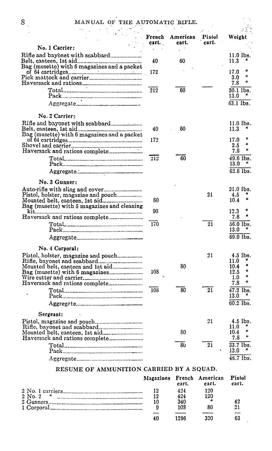
MANUAL OF THE AUTOMATIC RIFLE.
French
No. 1 Carrier:
Rifle and bayonet with scabbard....-......
Belt, canteen, 1st aid...............l.
Bag (musette) with 6 magazines and a packet
of 64 cartridges.........:..........-...
Pick mattock and carrier................
Haversack and rations..................
Total-------...................
Pack...........................
Aggregate.™-------------------
40
172
American
cart.
60
60
Pistol
Weight
11.0 lbs.
7.8 “
50.1 lbs.
13.0 “
63.1 lbs.
No. 2 Carrier:
Rifle and bayonet with scabbard.............
Belt, canteen, 1st aid........... .........
Bag (musette) with 6 magazines and a packet
of 64 cartridges...........................
Shovel and carrier....................-....
Haversack and rations complete___________
Total______________.._____________
Pack.............................
Aggregate.:.......................
40
60
11.0 lbs.
172
60
49.6 lbs.
62.6 lbs.
No. 3 Gunner:
Auto-rifle with sling and cover...........
Pistol, holster, magazine and pouch.......
Mounted belt, canteen, 1st aid........
Bag (musette) with 5 magazines and cleaning
kit................................ -....
Haversack and rations complete------------
Total...........................
Pack..........................-
Aggregate..................*----
80
90
21
21
21.0 lbs.
56.0 lbs.
13.0 “
69.0 lbs.
No. 4 Corporal:
Pistol, holster, magazine and pouch..
Rifle, bayonet and scabbard---------
Mounted belt, capteen and 1st aid...
Bag (musette) with 6 magazines------
Wire cutter and carrier...........
Haversack and rations complete-----
Total.....................
Pack......................
Aggregate.................
4.5 lbs.
108
80
10.4
108
80
21
47.2 lbs.
13.0 “
60.2 lbs.
Sergeant:
Pistol, magazine and pouch.....
Rifle, bayonet and scabbard....
Mounted belt, canteen, 1st aid—
Haversack and rations complete..
Total................
Pack
Aggregate............
4.5 lbs.
80
80
21
33.7 lbs.
13.0 “
46.7 lbs.
RESUME OF AMMUNITION CARRIED BY A SQUAD.
American
2 No. 1 carriers.
2 No. 2 u ......
2 Gunners_______
1 Corporal......
Magazines French
cart.
424
424
340
108
12
12
10
120
120
80
Pistol
40
1296
320
63
PART II
I DRILL
3. Definitions:
“Rifle Team” consists of a gunner, who is team commander,
and two carriers (a leader and a scout).
“Squad” consists of two rifle teams and a corporal:
Front Rank.—No. 1 Carrier (scout); No. 2 Carrier (loader);
No. 3 Gunner; No. 4 Corporal.
Rear Rank.—No. 1 Carrier (loader); No. 2 Gunner; No. 4
Carrier (scout).
“Section” consists of two squads and a sergeant.
“Short String” is a burst of two or three cartridges.
“Long String” is a burst of from four to six cartridges.
“Clip Fire” is a burst of eighteen cartridges, or the entire
magazine without pause.
.4. The training of the auto-rifle section has four phases:
(1 ) The individual instruction of the gunner.
(2 ) The training of the rifle team.
(3 ) The training of the squad.
(4 ) The training of the section.
5. Selection of the automatic rifleman:
All members of the Automatic Rifle Section must be healthy,
robust men. No other type will be able to carry the loads and
meet the demands that will be made upon them. They must be
intelligent and must be expert shots. Otherwise, the great fire
power which is put in their hands will be wasted.
6. Individual training:
The sergeant, corporal, the gunner and the two ammunition
carriers should receive the same instruction, so that all are able
to act as gunners and anyone of the section can continue the service
of the rifle if the others should be killed. The individual instruc-
tion should cover the following:
(1) The nomenclature and a thorough understanding of the
mechanism of the rifle.
10 MANUAL OF THE AUTOMATIC BIFLE.
(2) Stoppages and their reduction.
(3) Correct firing positions.
(4) Shooting single shots for a group.
(5) Placing of the group of single shots in the center of target.
(6) Shooting short strings of 3 shots.
(7) Long strings of 5 or 6 shots.
(8) Clip fire.
(9) Changing magazines.
(10) Fire at disappearing silhouettes with both short and long
strings.
(11) Firing without looking through the sights as a prepara-
tion for “marching fire.”
(12) Marching fire.
(13) Filling magazines.
(14) Target designation and the preparation of range cards.
7. The automatic rifle team:
The rifle team must be so trained as to get a maximum of
efficiency out of the efforts of the individual members. This
requires coordination of all their activities. The training should
include the following:
(1) Drill. The taking of the different formations, and the
duties of the gunner and ammunition carriers.
(2) Utilization of the ground and the disposition of the team
on different terrain.
; (3) Service of the rifle by two members of the team.
(4) Changing of magazines by No. 2 carrier. Loading of
empty magazines by No. 1 -while in position.
(5) Advance of the team as a whole.
(6) Advance of the team by rushing forward one man at a time.
(7) Opening and ceasing of fire by signal of No. 1 carrier.
8. For the efficient service of the auto rifle, a team of three
men is required—a gunner, a loader, and a scout—the gunner being
team commander. In an emergency, however, the gun may be
kept in action by two, or even one man, and for this reason it is
essential that each man be familiar with the duties of every other
member of the team. For drill, the team is formed in single rank,
right to left, scout, loader, gunner, or loader, gunner, scout. The
team deployed occupies the same relative positions with 5 paces as
the normal interval.
MANUAL OF THE AUTOMATIC KIFLE.
11
9. The sling:
The ordinary rifle sling, with the addition of two snaps, may be
used with the auto rifle.
To adjust the sling, place one snap in the loop made by the
short strap, and place the other snap in the loop made by the
long strap, and fasten snaps in front and rear sling swivels, re-
spectively. Adjust the large loop to fit over the left shoulder and
under the right arm. The size of this loop should remain fixed
after once being adjusted; all changes for other positions being
made on the short strap.
For close order, the sling should be of such a length as to allow
the rifle to be carried behind the right shoulder, with the sling
passing over the right shoulder only. For extended order, the
rifle is always slung as for marching fire. The rifle should be so
slung at any preparatory command for marching. /
During the execution of the manual, the rifle is kept at the
order arms.
10. Firing positions:
Prone.—In the prone firing position, the front part of the rifle
is supported by the bipod, the barrel bisecting the angle between
the legs, which are inclined to the rear as far as the mechanism
will allow. The butt is held firmly in the hollow of the right
shoulder, the right hand on pistol grip, the left hand on carrying
handle, the right cheek firmly against barrel cover, in front of
the rear screw collar. The body is placed as nearly as possible in
prolongation of the line of sight. The right hand exerts an upward
and backward pressure, the left hand a downward and backward
pressure. Note: men with high cheek bones will find it necessary
to incline the body to the left in order to get a correct sight.
The loader places himself on the right of and on a line with the
gunner, his body parallel to the line of sight.
The scout places himself five yards to the right or left of the
his gun.
11. Marching fire:
The rifle is supported by the sling, which passes over the
gunner’s left shoulder and under his right arm (for adjustment of
sling see paragraph 9).
The gunner grasps the carrying handle with his left hand and
the pistol grip with his right hand, and exerts a downward and
outward pressure. The butt is held against the front of the right
hip. The body is bent well forward from the waist.
12 MANUAL OF THE AUTOMATIC BTFLE.
The loader marches to the right rear of the gunner, his left
hand on the gunner’s right shoulder.
The scout marches five paces to the right or left of the rifle.
12. Duties of members of the rifle team in prone fire:
The gunner.—(1) To direct his fire on the target.
(2) In loading, to pull the operating handle back and cock the
rifle, at the same time turning the barrel slightly to the left with-
out lowering it from his shoulder.
(3) In changing magazines,“same as sub-head two, and in
addition, to press forward on the magazine catch with his left
thumb, releasing empty magazine.
(4) When firing alone, to pull back operating handle and cock
the rifle, drop the butt to the ground turning the barrel to the left,
at the same time pressing the magazine catch forward with the
left thumb, removing the magazine with the right hand; to insert
a new magazine with the right hand, exerting slight pressure on
the magazine catch with the left thumb, until the magazine is
firmly seated.
The loader.—(1) To watch for signals to commence or cease
firing and to transmit same to gunner by two taps on the shoulder.
(2) To watch the ejection opening for stoppages during firing
and to aid in reducing same.
(3) To watch the magazine for stoppages, and, when same is
empty, to notify the gunner by calling “magazine,” withdrawing
the empty magazine with the left hand.
(4) To remove empty magazine with the left hand and insert
the new magazine by grasping it in his right hand, placing the
magazine spring stop between the side plates, behind the bipod
transom and shoving magazine home with a sharp upward motion,
care being taken not to damage the magazine. Throughout this
operation he steadies the rifle by placing his left hand on the
housing, behind the rear sight.
(5) When his own magazine bag is empty, to exchange with the
Scout and Corporal successively. (The gunner’s ammunition is
kept as a reserve.)
(6) To carry the hand extractor available for immediate use
during fire.
’ The scout.—(1) To exchange magazine bag with the loader.
(2) To fill empty magazines.
MANUAL OF THE AUTOMATIC IUTLE. 13
(3) To spot shots for the gunner. .
(4) To act as scout and protect the rifle team when the rifle is
out of action.
The duties of the members of the rifle team are the same in
marching fire as'when firing prone. The loader is responsible for
keeping the gimner on the line and preserving the interval.
13. The following drill should he given to insure the gunners
cocking the rifle at each loading operation and may be used in
any class of fire:
(1) Load.
(2) Fire.
(3) Magazine.
At the first command the gunner cocks the rifle. The loader
inserts an empty magazine. The gunner then lays on the target.
At the second command the gunner pulls the trigger. At the third
command, the gunner cocks the rifle, releases the magazine and
turns the barrel to the left, keeping it at his shoulder. The loader
removes the magazine and inserts another. The last two com-
mands are repeated as long as the instructor desires.
14. Being deployed, to commence firing:
(1) Range, two hundred (three hundred, etc.).
(2) Target, skirmish line, at one o’clock. -
(3) Short strings (long strings, or clip fire, etc.).
(4) Commence firing.
(5) Cease firing, or suspend firing.
At the first command the team assumes the prone firing position
as explained in par. 10, and the gunner sets the sights. At the
second command the gimner lays on the target. During the firing
the team performs the duties as explained in par. 12. At “Cease
Firing” the magazine is removed, the gunner pulls the trigger, and
turns the barrel to the left, dropping the butt to the ground. In
other respects the team maintains the prone position. At the
command “Suspend Firing,” firing stops; rifles are held, loaded
and locked, in a position of readiness for an instant resumption of
firing, rear sights unchanged.
15. Being deployed, to lie down. Lie down:
The gunner: (1) Advances the left (right) foot and drops on the
14 MANUAL OF THE AUTOMATIC BIFLE.
right (left) knee, swinging the “bipod legs’' well to the front and
dropping them to the ground. . ..
(2) Drops butt to the ground, and shoots both legs to the rear,
supporting himself on his right (left) elbow, and by his grip on the
handles.
(3) Turns barrel to the right and disengages front snap. (When-
ever sling is adjusted for marching fire.)
(4) Assumes prone firing position, cocking rifle.
The loader: (1) Jumps immediately to the side of the gunner
and drops to the ground, swinging ammunition bag well to the
front.
The scout: (1) Closes at once to five yards from the gun and
drops to the ground, swinging ammunition bag well to the front.
16. Being deployed, to commence marching fire:
(1) Marching Fire.
(2) Commence firing.
(3) Cease firing.
At the first command, the gunner brings his rifle to the march-
ing fire position and cocks it. The loader jumps to the side of the
gunner and inserts a loaded magazine. The scout closes to five
yards. At the second command, team steps off (if halted), and
commences firing. The loader keeps his left hand on the gunner’s
right shoulder to steady him, to prevent his halting and to pre-
serve the alignment. At the command “Cease firing,” the maga-
zine is withdrawn from the rifle and the loader and scout assume
their normal intervals.
17. The squad:
The squad drills in close and extended order as prescribed in
the I. D. R.., except as herein stated.
18. Duties of the corporal:
(1) To watch for signals from section or platoon leader, and
repeat same back.-
(2) To assign rifle positions, sectors of fire, and to designate
targets.
(3) To exercise general supervision over rifle teams.
19. Being in line, to deploy:
J (1) As skirmishers.
(2) March.
MANUAL OF THE AUTOMATIC ELFLE. 15
The corporal places himself in front of his squad, if not already
there. Moving at a run, the front rank men place themselves
abreast of, and on the right of the corporal at 5 paces intervals,
the rear rank men place themselves abreast of and on the left of
the corporal at 5 paces intervals.
20. Being deployed, to advance by rushes:
(1) By team (one man) rush:
The squad leader gives the signal “advance by rushes” as
prescribed in the I. D. R., and, in addition, holds up one finger if
the advance is to be made one man at a time, and three fingers
spread if it is to be by team. If the advance is by team, the whole
team rushes forward at once, maintaining their normal intervals.
If the rush is by one man, the scout is the first to go forward. He
advances to the position he wishes to occupy, taking advantage
of all cover afforded by the terrain or by intervening shell-holes.
In general, this advance should not be more than fifty yards.
With his intrenching tool he prepares a position for the gun and
then signals to the gunner “Ready.” The gunner then advances
in the same manner and opens fire as soon as his gun is in position,
the scout serving the rifle until the loader arrives. The loader
after picking up all magazines, advances. If the advance is made
from a trench or a shell hole each man should leave from a different
point, as a sniper might train his sights upon any fixed point of
departure, shooting each member as he appears, successively.
21. Being in skirmish line:
(1) Squad columns.
(2) March.
Each squad leader moves to the front, followed in succession by
the front and rear ranks in single file.
22. Continuous fire:
(1) Continuous fire.
(2) Commence firing.
(3) Cease (suspend) firing.
At the second command, the gunner on the corporal’s right
opens fire. Just before his magazine is exhausted, the loader gives
the signal “Commence Firing” to the other team, the rifles thus
alternating fire.
16 MANUAL OF THE AUTOMATIC. RIFLE. '
23. When firing from shell holes, no fixed regulations can be
prescribed, the members of the team conforming as nearly as
possible to the positions laid down in par. 9.
In case of two rifles advancing singly, the advance of one is
covered by the fire of the other.
24. The section:
The section executes the movements and firings as explained
for the Team and Squad. The section leader normally takes post
in rear of the center of his section, but he may go wherever his
presence is needed.- — -------- - -
25. Except in ‘‘marching fire,” the section will seldom act as a
unit, but rather as two squads whose action will be supervised by
the sergeant of the section. The duties of the sergeant will thus
usually be those pertaining to fire direction rather than fire con-
trol. The sergeant, under the orders of the platoon leader, will be
responsible for the training of the section.
26. Being in skirmish line: |
(1) Section column of two.
(2) March.
The section leader moves forward through the center of the
section. The squad to the right of the section leader marches to
the left and follows him in file, the squad to the left marches in
like manner to the right. Each section leader then conducts the
march of his section in double column of files.
27. Being in skirmish line:
(1) Section column of files.
(2) March.
The section leader moves forward through the center of the
section; the squad to the right of the section leader marches to the
left and follows him in file; the squad to the left marches to the
right and follows the right squad in file.
PART III
COMBAT PRINCIPLES
CHAPTER I.
28. Characteristics of automatic rifles: ’
A clear understanding of the characteristics of automatic rifles
is absolutely necessary to their correct tactical use. A confusion
of ideas as to their powers and limitations will lead to a failure to
utilize them to the fullest extent, or to positive disaster by ex-
pecting from them functions which they are not capable of per-
forming. The confusion of the words machine gun and automatic
rifle has been responsible for a great amount of erroneous teaching.
An Automatic Rifle is a rifle which fires infantry ammunition on
the automatic principle, but its recoil is supported by the body of
the firer.
A Machine Gun is a gun that fires infantry ammunition on the
automatic principle, but its recoil is supported by some sort of a
fixed mount, and the direction of the fire is capable of being
clamped.
The automatic rifle is carried with the infantry in the assault.
It is placed in the first line of trenches. It is used under all cir-
cumstances with the infantry, as well as in any other situation
where an intense infantry fire of short duration, or limited bursts of
infantry fire, may be required.
29. Types of automatic rifle:
From the point of view of the method of operation, there are
two general classes of automatic rifles:
(1) Those operated by the direct recoil.
The Chau chat and light Maxim are examples of this type.
(2) Those operated by a small portion of the gas passing
through a port and acting on a piston or actuator.
The Lewis, light Hotchkiss and Benet-Mercier are examples of
this type.
Considered from the point of view of the method of cooling
there are two classes:
(1) Air Cooled.
20 ' MANUAL OF THE AUTOMATIC KIFLE.
(5) Casualties in the auto-rifle squads rapidly reduce the
power of ammunition supply.
(c) Its fire can be directed on only a limited area at a time,
whereas infantry fire can be either concentrated or distributed to
suit the wishes of the commander.
(d) The equipment of the auto-rifle squad is very heavy. The
Chauchat can be carried on the march only with difficulty.
34. The most important characteristics to be remembered are
that the auto-rifle must accompany the infantry platoon, and it
must be so organized as to have sufficient mobility; that it is not
suitable for overhead fire and must not be used for such; that it is
not suitable for indirect fire and that such use should not be
attempted.
CHAPTER II.
35. Automatic rifles on the defensive:
Principles of the defense.—The underlying principles of the
defense is to hold the line securely with the greatest economy of
men. It is necessary to bring an effective fire upon all the ground
immediately in front of the line across which the enemy can
attack. Since machine guns and automatic rifles are able to
paralyze the enemy’s attack by large losses in a minimum of time,
by sudden and overwhelming fire, they are the ideal weapons for
covering the ground in front.
Since the beginning of the present war they have been used
more and more to replace infantry fire for two reasons:
(«) The ability of the nations engaged to turn out a great
number of automatic weapons, since they are all essentially manu-
facturing countries.
(&) The great destructive power of modern artillery and the
great amount of it in use.
Where troops face each other for some time they are enabled
by photo-topography to know the exact disposition of each other’s
forces, and on account of the accuracy of their artillery, practi-
cally to obliterate the first lines. To avoid great losses, it is
advisable then to hold those front line trenches with auto-rifles
and thus have great fire power with a minimum of men.
Thus using small groups with very extended intervals, there is
great latitude in the exact location of the groups. This fact in
itself gives a great factor of safety, as there are always points In
MANUAL 01-' TUE AUTOMATIC КП’ЬЁ.
21
any line that are relatively much safer than others, and only these
will be occupied.
The following diagram illustrates the method of placing auto-
rifles in the most protected places and yet covering the entire
front with fire.
Suppose A and В are small knolls in a line of defense.^ The fire
trench for riflemen runs as shown by the dotted line X-Y. How-
ever, if mutually supporting machine guns or auto-rifles are placed
behind each knoll, the whole front is covered by fire. The rifles
are hidden from the enemy, and have practically an enfilade fire,
which is the most effective kind. This is an example of the best
method of placing auto-rifles. However, it requires more know-
ledge of the terrain than frontal fire, as there is danger of leaving
defiladed areas where the enemy can safely advance.
36. Scope of machine guns and automatic rifles:
Keeping in mind the definition and characteristics of the ma-
chine gun and auto-rifle, enables one to reach a correct solution as
to the roles of the two. The machine gun with its stable mount
and ability to give continuous fire should form the back bone of
the main defense. Its fire should be confined largely to indirect
and enfilade fire. The auto-rifle should relieve the machine gun
of short range direct fire, and should occupy places difficult of
access where its mobility comes into play.
37. Trench warfare:
Trench warfare involves a double system of trenches, deliber-
ately designed for defense, with the probability of the opposing
forces facing each other for a considerable period.
38. The front line:
It is generally conceded that either side, if willing to pay the
price, can take a front line at any desired point. The front line
should therefore not be the main line of resistance, where it can
be avoided. The purpose of the front line is, generally speaking:
|(a) To observe the enemy and give warning of an attack.
22
MANUAL OF THE AUTOMATIC KIFLE.
(5) To prevent the enemy from reconnoitering the line of re-
sistance, and to prevent his patrols and-raids from entering our
line. /
(c) In case of. a general attack, |to check the first move and
allow time for the main line and the artillery to be warned; to
inflict losses on the attackers, and if some do penetrate the line,
to fire upon their rear from points of resistance; to assist the
counter-attack of our troops by preventing enemy reinforcements
from coming up.
For these purposesofthe front line, no other weapon is as
useful as the automatic rifle. They interfere much less with the
fire of the machine guns than would an infantry line, as the ma-
chine guns can be sighted between them. While it may be essen-
tial to have a few machine guns in the front line trenches at im-
portant points, this use is exceptional. During the day there are
very few riflemen in the trench, and the front line can be said to
be held by auto-rifles. At night, more riflemen are required in
front line trenches.
Auto-rifles should be placed in pairs, with a traverse between
them if practicable so they cannot both be destroyed by the same
shell. They should be so placed as to give oblique fire. They
should be found in all salients.
39. Combat groups and strong points:
While the chief function of the auto-rifle is the defense of the
first line, this can often be best accomplished by placing them
outside the trenches, which are too plainly visible.
The best position for a combat group is an old shell hole con-
nected with a dugout through a tunnel. There is usually a steel
observatory, and the auto-rifle is set up only when the alarm is
given. Firing should never be done from these holes until the
moment of the enemy’s assault. Ordinarily no form of cover is
used.
These shell holes must be carefully masked, so that their real
nature may not be discovered by aerial reconnaissance. The
absolute necessity of hiding the firing positions requires the con-
struction of saps and galleries.
To use combat groups most successfully there should be about
150 yards between the front line and the main line, with the com-
bat groups between the two lines. There should be no com-
municating trench for 50 yards on either side of the combat groups.
MANUAL OF THE AUTOMATIC RIFLE.
23
In the larger combat groups and strong points, machine guns,
are usually used in conjunction with auto-rifles.
Strong points on a reverse slope are very effective.
40. The main line:
The basis of the main line is a series of machine gun emplace-
ments. Each machine gun fires obliquely to its front, and the
whole forms a continuous belt of fire across the entire front.
If the ground were perfectly level; if there were no obstructions
to their fire; and if they could be so placed in this’level country
that they would not be destroyed by artillery fire, they would
constitute a complete defense, but this condition never exists.
There will always be dead space over which the machine gun fire
will pass harmlessly. This space may be a stream, ravine, sunken
road, etc. The number and area of these dead spaces are increased
by the fact that machine guns are usually sited low so as to de-
crease their vulnerability to artillery fire. These are the areas
that must be covered by the fire of auto-rifles. They can be
fired over the parapet or be pushed forward to places that are
inaccessible for machine guns. The top of a flat ridge offers
another favorable opportunity for auto-rifles, as machine guns
would often be conspicuous and therefore would be destroyed by
artillery fire.
The role of the auto-rifle in the main line then is to supplement the
fire of machine guns. They cannot replace them.
The following sketch shows the location of machine guns and
auto-rifles, each covering the ground suited to it^andjdoing the
work properlyTinnts sphere:
41. Lines of fire:
The auto-rifle in^the^front^line should be allotted definite
areas to watch, each rifle firing obliquely to the front. The limits
24
MANUAL OF THE AUTOMATIC RIFLE.
of the area should be definitely located by objects readily seen by
the firer. A range card giving the information should be placed
at the position of each rifle.
Only under special circumstances should the gunner be per-
mitted to fire outside his sector. If a neighboring sector is raided
and everything is quiet in his own, the rifle may fire in the neigh-
boring sector, but one man must constantly watch the original
sector. At the least sign of activity in its own sector, the auto-
rifle must transfer its fire to that area.
42. Obstacles:
Wire should be placed so as to hold the enemy under enfilade
fire. A careful location of the entanglement will often make it
possible to get the enemy where a cross fire can be brought on
him by two auto-rifles. The arrangement should not be too ob-
vious or the enemy will avoid the trap. The following diagram
shows an arrangement of wire in which each line of wire is en-
filaded by one auto-rifle and the intersection of the two lines is
brought under a cross fire.
A. '----< '----'
43. Selection of targets:
The auto-rifle should fire only when targets are offered that
warrant the expenditure of ammunition or the disclosure of posi-
tion which is involved in the firing. The sniper is the man to deal
with individuals of the enemy. With his special equipment of
telescopic sights and periscope he will be much more successful
than will the auto-rifleman. This is specially true of the Chauchat,
as it has not the accuracy of the Springfield rifle. If the auto-
rifle is in a position which exposes it to attack by grenadiers,
ordinary riflemen or grenadiers should protect it.
44. Emplacements:
Elaborate emplacements must not be used, as they render
the auto-rifles conspicuous. The auto-rifle can be fired from any
trench suitable for rifle firing, but definite firing places must be
assigned. These places may be Ipopholed, but, iq the mpre
MANUAL OF THE AUTOMATIC KIFLE.
25
recently constructed lines, the usual firing place is a depression
running obliquely across the parapet. - This type gives the correct
line of fire, is less visible from the front, and gives to the firer a
certain amount of protection. If the auto-rifles are placed close
to a high traverse considerable protection from shrapnel is ob-
tained.
Each auto-rifle should have several firing positions, as this
materially lessens the chance of detection. Firing places in the
main line of resistance that are intended for use at the moment of
the enemy’s assault should never be used at any other times, as
they are likely to be discovered by the enemy and destroyed
before the actual assault.
45. Shelters:
Auto-rifles should be kept under cover in the day time or
during a bombardment. There will almost always be warning
enough to get the auto-rifle into position, as it can be handled
about as readily as an ordinary rifle. One member of the auto-
rifle team in observation near the firing place will be sufficient.
The remainder of the team can remain in their dugouts. At
night, it will be necessary to have more men at hand.
46. Ammunition:
Recesses for auto-rifle ammunition should be distributed all
along the trench, so there will be no considerable length of trench
without its ammunition supply. The recesses should not contain
more than 20 magazines, so that the loss from a single shell would
not be great. The exact location of these stores of ammunition
should be known to every auto-rifleman, and certain men should
be assigned to keeping the magazines and ammunition in perfect
condition.
47. Patrols:
While auto-rifles will seldom be of use with patrols in trench
warfare, they can render great assistance to the patrols if pushed
forward from the first line to shell holes where they can protect
the flanks of the patrol and cover its retreat if it becomes neces-
sary.
48. In the main line of resistance:
A clear field of fire at short ranges is far more important than
at long ranges. The auto-rifle has not the stability which gives
great accuracy at long range as has the machine gun. Its endur-
ance is such that if it is brought into action while the enemy is at
26
MANUAL OF THE AUTOMATIC RIFLE.
long range, it will probably he out of action in the critical stages
of the assault.
49. With outposts:
Auto-rifles can be of great value in covering roads, bridges,
stream crossings, and covering avenues of approach generally.
They should be assigned to the line of resistance and to the larger
bodies on the line of observation as pickets.
50. 'The use of autc>rlfles in the consolidation of captured
ground is dealt with under the attack.
CHAPTER III.
51. Automatic rifles in the attack, trench warfare:
Trench to trench attack.—The use of the auto-rifle in trench to
trench attack should be considered under four heads:
(1) The preparation.
(2) The assault.
(3) The reduction of strong points and centers of resistance.
(4) The consolidation of the ground and the exploitation of the
success.
52. The preparation usually extends over a considerable period
of time and provides for a multiplicity of details that hitherto have
been considered not only impracticable but impossible. Trench
warfare has become so complex that a satisfactory solution of any
situation is possible only where all contingencies have been thought
of and provided for in advance.
(a) The reconnaissance.—Plans cannot be made until certain
information as to the enemy’s dispositions is available. A great
part of this information is provided by aerial reconnaissance in
the form of photographs. They report the positions of trenches,
guns, etc., as well as the billets of the troops in rear of the line and
the probable avenues of approach if it should become necessary
for them to reinforce.
The infantry reconnaissance consists largely in patrols and
raids. The purpose of these is:
(1) To discover the strength of the front line and any arrange-
ments for assault, openings made in the wire, etc.
(2) To capture prisoners from whom the enemy’s intentions
may be learned.
(3) To destroy materiel.
(4) To determine the exact lipe of the epemy’s barrage.
MANUAL OF THE AUTOMATIC BIFLE.
27
In both patrols and raids the chief function of the auto-rifle is
to protect the flanks of the raiding party. At the beginning, it
will seldom be possible for them to be useful in any other way.
After the patrol or raid has accomplished its purpose or if it has
been driven back and is returning to its own lines, the auto-rifles are
of great value in covering its return. Whatever the outcome of
the raid, the raiding party probably will be fired upon by machine
guns before it is safely within its own lines. Auto-rifles pushed well
to the front and flanks can do much to neutralize and render
ineffective the fire of these guns.
(&) Provision for the supply of magazines and ammunition
during the assault must be made, and carrying parties from the
dumps forward must be provided for. The load of the auto-
rifleman is normally near the maximum limit, and he cannot be
further loaded down if he is to do his part in the fight. Neither
can the ammunition he carries be expected to last him during the
assault and the consolidation.
(c) The rehearsal.—A replica of the trenches to be attacked is
staked out and the troops to make the assault are practiced over
this course. The positions to be occupied by the auto-rifles in the
consolidation can be roughly assigned. In this way, the load that
each team will have to carry can be determined. Squads going
on’у a short distance can carry more ammunition. With squads
assigned to the flanks this is especially important, as upon their
holding their ground often depends the success or failure of the
assault. Units going to the farthest objective should carry less
ammunition, as they should be able to keep up with the artillery
barrage, and at the finish should be fresh enough to quickly con-
solidate the captured ground. Extra ammunition for them will
have to be provided for by extra carriers.
(d) Keeping open the gaps in the mire.—For days before the
assault, the artillery barrage attempts to destroy the wire en-
tanglements and all obstacles. Once gaps are made in the wire, it
becomes the duty of the auto-rifles to keep them open. This will
be especially difficult at night, as every effort will be made by the
enemy to repair these gaps.
53. The assault has its time regulated by the artillery and
machine gun barrage. If the assault is to succeed, it must follow
so closely behind the barrage that there will be no opportunity
for the enemy to get up out of his dugouts and man his trenches
and machine gun emplacements.
28 MANUAL OF THE AUTOMATIC BIFLE.
The place for auto-rifles of the Chauchat type, using marching
fire, is usually in the front wave of the first line.
In order that the enemy may have no definite information as
to the moment of beginning the assault, part of the auto-rifles
should continue firing from the jumping off trench until the march-
ing fire has begun. It will seldom be profitable to mass more
than 8 auto-rifles for this fire, as a greater number becomes a con-
spicuous target for the artillery.
Marching fire has advantages and disadvantages, but the
advantages seem to outweigh the disadvantages. The advantages
are: ~--------------------
(1) That it needs very little preliminary arrangement. The
gunners using marching fire simply go forward with the first wave.
(2) If the gunner is not hit and keeps up, the fire is continued
throughout the assault, and on arriving at "the enemy’s trench the
auto-rifle can be fired into it.
(3) If any of the enemy try to escape, the gunner can pursue
them with fire while he actually pursues them on foot.
The disadvantages are:
(1) That the fire of the auto-rifle is much less accurate and
therefore has less effect. Any trained gunner firing from the
bipod on the ground ought to be able to get effect on personnel at
once, at close range; firing from the hip, his aim is much less
accurate and the effect is more moral than material.
(2) When strong opposition is encountered and the assaulting
troops have many casualties, the conspicuous gunners will be the
first to fall. Thus in the event of an initial failure, when all the
rifles have been placed in the first line, no auto-rifles will be so
placed that they can cover the reorganization, or the withdrawal
of the unsuccessful troops, as is the case when they occupy con-
cealed positions in the front. The gunners are most likely to fall
in some zone of fire where it would be very difficult for other
members of the team to detach their auto-rifles and slings from
them. Every auto-rifle gunner should be taught when advancing
on the flanks to watch half right or left, to guard against flank
attacks from machine guns, as they will prove very disastrous to
our troops if neglected, because in the advance every one’s atten-
tion is centered on the immediate objective in front.
An auto-rifle is best suited to repel such an attack, as it can
change front instantly, while it would take some time and cause no
small loss to wheel enough riflemen to the flank to repel such an
attack.
MANUAL OF 4ГНЕ AUTOMATIC RIFLE.
29
54. Combat Groups, strong points, and supporting points:
The above names are applied to the “islands” of resistance of a
defensive position, according to the strength of the body of troops
occupying them. Those held by a platoon'or less are called
“Combat Groups.” Those made up of more than one “Combat
Group” and held by more than one platoon and not exceeding a
company are called “Strong Points.” Those centers of resistance
made up of several “Combat Groups” and “Strong Points” and
held by more than one company are known as “Supporting Points.”
In every case the general line of action involved in their reduc-
tion is the same, the platoon sends out squads, the company sends
platoons, and the battalion sends companies to get around the
enemy’s flank and cut off his retreat and reinforcements.
The usual small combat group used by the Germans is the
machine gun emplacement, armed with a single gun and situated
to gain surprise flank fire. These combat groups are sited in the
most unexpected places and are so skillfully concealed that they
are impossible to locate from the ground or from the air. It is
therefore essential that the officer commanding be constantly on
the lookout for such surprises, and that he act quickly and de-
cisively when the crisis comes.
A valuable point to note about the heavy sledge on which the
German machine gun is most often mounted is that it permits of a
traverse of only 30 degrees. This means that it can traverse only
half the width of the range at which it is firing; i. e., if it opens fire
at a body of troops at 300 yards range, a force sent off to outflank
it will be perfectly safe if it starts its enveloping movement 150
yards to a flank, and will probably be safe at 100 yards to a flank.
Thus a German machine gun, on a sledge mounting, which had
opened fire on a line of men, would have to have its mounting
moved to enable it to fire at the outflanking party, and this would
permit of the advance of the party at which it first fired.
Even if the machine guns were mounted on some mount the
same principle holds good, for a machine gunner cannot watch
several sides at once. Moreover, a machine gun with an all-round
traverse must be less under cover than one firing from a loop hole.
It cannot have a covered emplacement, nor be defiladed from any
direction, so all flanking parties have a good chance of silencing it.
If the ground allows it, the simultaneous attack from both flanks,
while the gun is kept occupied to the front, is to be recommended.
The role of the auto-rifle in such an attack is either to open
30
MANUAL OF THE AUTOMATIC RIFLE.
fire at once at the machine gun while other sections work around,
or it can be sent around with one of the flanking parties.
The first is the natural course when an enemy machine gun
opens fire unexpectedly or when a platoon finds itself in an un-
favorable position, for in such cases it is important for the auto-
rifle to get into action at once to cover the movement of the
remainder. It is generally found that the auto-riflc monopolizfcs
the attention of the machine gun, and.the remainder of the platoon
can maneuver with little loss; also, if the machine gun is firing
through a loop hole, the auto-rifle can put it out of action only from
the direction in which it isffiring.
The second method, to send the auto-rifle around a flank, is
often advisable when the position of the strong point has been
ascertained before the advancing platoon comes under fire. It is
particularly to be recommended when the strong point takes the
form of a trench line which can be enfiladed. The enemy is sure
to be disconcerted when heavy fire is brought upon him from an
unexpected quarter, and the auto-rifle can often be sited in a posi-
tion from which it can cut off his retreat.
In all attacks on combat groups, the covering fire of auto-
rifles is of the utmost importance, as usually no artillery is present,
and it is necessary to supplant artillery fire effect as much as
possible by the fire effect of small arms.
Covering fire may be gained in two ways:
(1) By pushing the auto-rifle well ahead of the line of con-
cealed positions, or from commanding positions in the rear.
(2) By using marching fire.
55. Reduction of strong points and supporting points:
The most difficult part of the assault is the reduction of centers
of resistance formed by machine guns, auto-rifles, and grenadiers
in shell holes. These centers may come in the way of a surprise
or may not, depending on whether or not the aerial photographs
have revealed them. If they have been revealed, detailed prepara-
tion is made beforehand. If they come as a surprise, the battalion
commander must act promptly, as the attack will be absolutely
held up until the center of resistance is destroyed.
The troops detailed to attack a strong point would ordinarily
be rifle grenadiers, machine guns, hand bombers, riflemen, and
auto-rifles.
The French have worked out the attack of strong points in
great detail. Their scheme is given below, not as a normal method
MANUAL. OF THE AUTOMATIC BIFLE.
31
but as an illustration of how a strong point might be reduced,
under certain circumstances. The method to be used in any par-
ticular case must be fitted to the particular circumstances of that
case.
The troops detailed for this particular operation are 32 rifle
grenadiers, a machine gun company, 24 automatic rifles, and a
platoon of riflemen and hand bombers.
The attack consists of 3 distinct phases:
(1) Fire preparation.
(2) Advancing with marching fire.
(3) The cleaning up of the trenches.
First Phase.—Fire Preparation.—(a) Systematic fire of the
machine guns and auto-rifles and riflemen to cover the rifle grena-
diers while they are getting into position and carrying on the
bombardment.
(6) Systematic bombardment of the center of resistance by
rifle grenades.
The rifle grenadiers should be distributed in groups of 4 to S,
in an enveloping formation, so as to be able to bring converging
fire. A couple of Stokes mortars would add greatly to the strength
of this bombardment (see sketch).
Second Phase.—The Assault.—When the bombardment has
reached its greatest intensity, the assault is made by the auto-
rifles, firing while marching. There must be no interval between
the fire of the grenades in the bombardment and the marching
fire, as the most important thing is to leave the enemy in his
dugout in ignorance concerning the beginning of the assault.
The machine guns should be so placed as to fire as long as
possible (see sketch).
Third Phase.— The Cleaning Up of the Trenches.—Under cover
of the marching fire, the platoon of bombers advance in groups of
squads. As soon as the trenches‘have been reached, the bombers
begin cleaning up systematically. The bombers work in the
trenches and the 6 auto-rifles on the surface. If the communicat-
ing trenches have sectors of much length, the auto-rifles may do
great execution. They may also prove of great value in covering
trench crossings and preventing the reinforcement of the enemy’s
bombers or resupplying of grenades.
As soon as the cleaning up has reached a satisfactory stage,
the advance of the battalion continues.
reduction of л strong point. — First phase : Fire preparation.
ist company of
reduction of л strong point — Second phase : The marching fire. Advance of the platoon of grenadiers.
MANUAL Of THfc AUTOMATIC ЙЕЕТЁ.
34
MANUAL OF THE AUTOMATIC BIFLE.
For the successful attack of a center of resistance the following
details must be arranged:
’ (1) The front of the attacking company must be reduced in
order to facilitate operations.
(2) Distribution of the*rifle grenadiers and auto-rifles.
(3) Assignment of selected men for the marching fire.
(4) Place and formation of the platoon of riflemen and hand
bombers.
(5) Sectors of-fire assigned the machine guns.
Only the most careful and detailed preparation will nake the
assault a success.
56. Woods:
Voods of small and medium sizes are especially likely positions
in which to find strong points located, and there is really only one
good way of attacking such a point.
If the wood has been subjected to artillery fire, the task is
made more difficult, as the fallen trees merely give more cover to
the enemy and make passage almost impossible.
Most organized woods are cut by belts of fire that cross each
other at right angles and divide the woods into sectors.
In attacking such a place, the first move should be to flank it
and enfilade the belts of fire; in this way the enemy’s.communica-
tion can be greatly interferred with and his movements from one
sector to another, either to reinforce or retreat, may be stopped.
After the woods have once been entered, no aid from the
artillery can be expected, as it is impossible for observers either
on the ground or in the air to tell the positions of either our own
troops or those of the enemy.
After the wood has been taken, it should be vacated and the
line consolidated in front, as enemy artillery is sure to have the
exact range and will commence shelling as soon as it receives word
that its own troops have been driven out. Also if our line is in
front of the woods, where communication can be gained with the
aeroplanes, the task of our artillery is made much easier.
In the case of a very large wood, which cannot be takenln one
operation, it becomes necessary to consolidate a line within the
wood itself. Some prominent line such as a-road, a belt of fire,
or a ridge should be chosen for this purpose.
The rear side of each cleared belt should be made impassable
by making obstacles of barbed wire, boughs, etc., so that if the
enemy tries to rush across, he will be caught and held under the
fire of a machine gun or auto-rifle. All passage by our own troops
MANUAL OF THE AUTOMATIC BLFLE.
35
from front to rear should be along fixed trails, as the gunners are
required to fire at anyone who tries to cross at any point other
than those trails.
A good method of making these trails easy to follow in the
dark, is to stretch a wire along the side about waist high, so that
a man can follow the wire with his hands.
The front of each belt of fire should be well camoflaged, so
that the enemy will be unable to locate them.
57. Villages:
The method of attack used in woods is equally applicable to
villages, using the streets in the sAme way that the belts of fire
were used in the woods. The auto-rifle is especially valuable in
such a place, as it can fire from windows, towers, roofs, walls, etc.,
where it would be impossible to get enough riflemen to gain an
equal volume of fire. The village is taken, block by block, as the
wood is taken sector by sector.
As in the case of woods, and for the same reason, the village
should be left as soon as taken, and a line established in front of it.
58. Neutralizing the fire of machine guns that have survived
the barrage is one of the most important duties of the auto-rifle
in the assault. No matter how thorough the preparation is, there
will always be a few isolated machine guns that have lived through
it, and they must be given prompt attention and their fire rendered
ineffective.
59. If gaps in the assaulting line have to be filled, the quickest
and most effective method of doing it is to order up auto-riflcs
from a reserve company.
^?'6O. After the assault, the auto-rifle really comes into its own.
It becomes temporarily the most important arm of the assaulting
troops. It is'the time that requires the greatest daring and
initiative on the part of the auto-rifle squads. No delay nor
hesitation is permissable. For this reason, assignments should be
made prior to the assault for the following duties:
(a) iConsolidation of the ground won.
(b) I Establishment of outposts.
(c) Sending out of contact patrols.
61. Consolidation of the ground:
The general position on which the troops are to consolidate is
usually selected^before the assault. When this position is reached,
the auto-rifles must take immediate measures for holding the
36
MANUAL OF THE AUTOMATIC BIFLE.
ground. Experience has^shown that it is impossible for the ma-
chine guns to keep up with the assaulting troops. The auto-rifle
must establish belts of fire all along the front until this duty can
be taken over by the machine guns. This enables the machine
guns to make proper reconnaissance, so they will not go into
positions which later will prove to be untenable. With the auto-
rifle, the important consideration is to get into some position at
once, from which an effective fire can be delivered. If it later
develops that the position is unsuitable, the auto-riflemen can
easily move.
The line of consolidation should not be the enemy’s old line, as
this position will be accurately'located on the maps, and artillery
fire can be brought to bear on it with much less delay. This line
should preferably be established a short distance beyond the
enemy’s line. The flanks of units should be well covered by auto-
rifles until the positions of neighboring units are determined.
The first few minutes after the new line is reached are among
the most critical of the whole assault, as it is at this time that the
enemy will make his counter attack. It is at this time that the
auto-rifle has its greatest usefulness.
62. Outposts:
As soon as the consolidation begins, outposts are established.
These usually consist of about a squad of riflemen, with an auto-
rifle. Such groups should be pushed out about every 150 or 200
yards along the front. They take cover in shell holes, altering
them only as much as is absolutely necessary for protection. It
is important not to attempt to link them up and make a continuous
trench at this time, as it gives information to the enemy as to the
position. , This will be found out later, but a few minutes delay at
this stage may be of extreme importance.
63. Contact patrols:
The battalions must not be content with the capture of the
assigned objective. | lit is possible that the enemy has been so
demoralized that he has abandoned further ground or can be
driven from it with practically no resistance. If he is given time
to recover, he may reoccupy this ground, and make the operation
of taking it very expensive. • Contact patrols must-be sent out at
once, to determine the exact statusjof the ground in front’and'to
take possession of any unoccupied ground. The French call these
MANUAL OF THE AUTOMATIC KEFLE. 37
patrols “Antennae” and have prescribed a normal operation for
them.
Each company sends out one or two contact patrols, which are
constituted as follows:
One Bombing squad.
Two auto-rifle squads.
One rifle grenadier squad.
The whole to be commanded by a platoon leader.
Rifle squads may follow as a support if desired.
64. The formation of the patrol:
The terrain is cut up, and usually the communicating trenches
obliterated, but the shell holes afford cover. The patrol must
attempt to advance without being seen especially it must never
offer a favorable target to the enemy.
The hand bombers form a line with extended intervals. The
platoon leader follows at about 20 paces, and is in turn followed by
the rifle grenadiers at about 10 paces. The auto-rifles are distrib-
uted on each flank. The rifle squad follows in rear as a support.
65. The advance of the patrol:
The bombers advance, one man at a time, by rushing from one
shell hole to another. They keep in touch with the squad in rear
by signals, and attack in order to push the reconnaissance.
The rifle grenadiers establish a semicircular barrage extending
from 80 to 150 yards to the front, to clear possible cover.
The aulo-rifles, two on each flank, have one of these two directly
supporting the hand bombers by sweeping the open places, and
the other covering the flank. The auto-rifles, which cover the
flanks, co-operate with the neighboring patrols and prevent the
enemy from counter attacking through the intervals between
patrols.
66. Overcoming resistance:
Two kinds of obstacles to the advance are encountered, hostile
grenadier groups or nests, and machine guns established in shell
holes.
As soon as a nest of hand bombers is encountered, it is attacked
by our hand bombers. The hand bombers establish a smoke
barrage, by means of/grenades, to cover their movements. The
rifle grenadiers establish a barrage in rear of the nest to isolate the
38
MANUAL OF THE AUTOMATIC RIFLE.
group and prevent reinforcements. The auto-rifles protect the
front and flank of the hand bombers.
If machine guns are encountered, the automatic rifles open fire
and attempt to drive the machine gunner to cover. Covered by
this fire, the rifle grenadiers close in to within range and open a
systematic bombardment. As soon as the machine gun has been
rendered ineffective, the grenadiers advance. In this attack, it is
desirable to separate the rifle grenadiers into two groups so that
they can brihg a converging fire.
67. The British attack a machine gun in a slightly different
manner. They open fire with Lewis rifles to cover the advance
of the rifle grenadiers. When within range, the rifle grenadiers
open fire on the machine gun with incendiary and smoke grenades.
Under cover of the smoke, the bayonet men go forward and at-
tempt to gain the flank of the machine gun, when they rush it and
put it out of action.
68. Organization of the terrain:
When the contact patrol has reached the assigned objective,
a position is taken up in shell holes. The grenadiers occupy the
advanced points, while the auto-rifles take up a flanking position,
slightly to tie rear. This marks the line which must be quickly
consolidated for the counter attack. It will be necessary to rein-
force these patrols by riflemen.
CHAPTER IV.
69. Automatic rifles in open warfare:
The tactical use of all weapons, being determined by their
innate characteristics, powers, and limitations, the general
principles of the use of automatic rifles in open warfare remain the
same as in trench warfare, the only necessity being to adapt these
general principles to the changed conditions which are presented.
The automatic rifle has been developed on the western front
during the present war, where trench warfare has so far been the
rule. It has npt as yet proved its value in open warfare.
Generally speaking, its value results from its greater mobility,
as compared to the heavier machine gun, and its greater volume
and flexibility of controlled fire, as compared to the ordinary rifle.
It being an intermediatejweapon between the ordinary rifle and
the machine gun, having some of the characteristics of each, it
MANUAL OF THE AUTOMATIC BUTE.
partakes of some of the functions of each. For example: In cases
where machine gun fire would be desirable, and either the ma-
chine guns are not available or are not sufficiently mobile for the
particular situation; in cases where not a sufficient number of
riflemen are available or there is not sufficient room in which to
deploy the number necessary to give the requisite volume of fire.
It is a special weapon and its correct uses are confined to
special circumstances—the reliable, all around weapon of the
infantryman being the rifle and bayonet.
It is particularly adapted to defensive use, where ample supply
of ammunition is easy and where the rifle and ammunition for it
does not have to be carried continuously nor for great distances.
It is particularly adapted to outpost work where the main
object is to hold the line with as few men as possible, giving troops
in rear time to prepare for action.
ATTACK.
In the attack, when the zone of effective hostile machine gun
fire is reached, the automatic rifles should usually be in rear of the
front line, ready to move to the flank or to support an/ threatened
portion of the front line.
In the advance during the infantry fire fight, up to the assault-
ing position, the automatic rifles assist in covering the advance
from the flanks or by overhead fire from commanding positions in
rear. This does not mean that the automatic rifle should be used
for indirect fire, nor for overhead fire except from high ground in
rear. •
In the assault, the automatic rifles may be used for marching
fire in the first wave or may cover the advance from the flanks or
from commanding positions in rear as above.
After the assault, in case the pursuit is not immediately taken
,up, the automatic rifles are pushed forward to hold the captured
position against a counter attack and utilized in outposting the
position.
In case of a retirement being ordered, the automatic rifles
assist in covering the retirement, using enfilade flanking fire
whenever possible.
70. Defense:
In open warfare, as in trench warfare, the defense will normally
be intrenched, the only differences being that the intrenchments
will be less elaborate, there will be fewer lines of trenches in the
40
MANUAL OF THE AUTOMATIC EIFLE.
direction of depth, and, instead of one continuous line from Switzer-
land to the sea, the defensive positions will have flanks. The
defensive uses of automatic rifles, as stated for trench warfare,
are equally applicable to open warfare.
In the selection of positions for automatic rifles, it should be
borne in mind that, except at very favorable targets, the auto-
matic rifle should never be used at ranges greater than 600 yards.
(Owing to the inaccuracy of the Chauchat at the longer ranges, it
should not be used beyond 400 yards).
The positions selected-should be so located as to enable the
automatic rifle:
(1) To defend flanks.
(2) To defend intervals between trenches.
(3) To enfilade ground depressions.
(4) To cover defiles.
(5) To compensate by volume for short field of fire.
(6) To occupy locations that do not admit of deployment of
sufficient riflemen to develop the necessary volume of fire.
PART IV
MECHANISM
CHAPTER I.
DESCRIPTION AND NOMENCLATURE OF THE RIFLE.
71. Characteristics:
The automatic rifle, 1915 Model, is an automatic rifle utilizing
the force of recoil. It is classed among the rifles of this category
in which the barrel recoils the full length of the stroke.
It fires the French regulation cartridge 86 D (with modified
priming). The feeding is done by magazines containing twenty
cartridges. This rifle can be fired semi-automatically (single
shots) or automatically (continuous fire).
72. Description and nomenclature:
The rifle is divided into two principal parts:
(A) A non-recoiling part.
(B) A movable part.
73. (A) Non-recoiling part:
The non-recoiling part includes:
(1) The housing.
(2) The receiver.
(3) The firing mechanism.
(4) The fittings.
74. The Housing:
Is made out of steel tube. It is used to protect the barrel and
to guide its movements. It is formed of two tubes, fixed together
by the front assembling collar, and carries as its fore part the
flash screen, screwed and riveted on, and the front sight, which by
its truncated shape decreases the internal diameter of the housing,
constituting a recoil intensifier.
The housing is drilled in front with eighteen holes, allowing the
circulation of the air around the radiator.
On the right the ejection opening; below the feed piece opening,
in which the feed piece is fixed to the bolt slides. The groove is
hollowed out at its rear end to allow the mounting and dismount-
ing of the feed piece; at its forward end, to allow the movement of
the cartridge guide.
The back part of the housing ends in the rear assembling collar,
in which is screwed the plug carrying the recoil springs.
The plug includes: The plug itself; the threading and the spring
guide tube.
42
MANUAL OF THE AUTOMATIC BEFLE.
The front and rear assembling collars carry, respectively, an
assembling clasp and a perforated stud, allowing the securing of
the housing on the receiver by means of th^ assembling bolts.
The front assembling collar has internally a recoil shoulder
against which the barrel sleeve bushing strikes when the parts are
at the firing position.
On the middle part of the housing the rear sight is fixed.
75. The receiver:
The receiver is formed of two side plates joined by blocks and
fastened at the back to the stock.
On_the_right_aide_pbte are tOLbe seen:
The axis holes of the sling swivel, of the front assembling bolt,
of the cartridge guide rod guide; the holes for the passing of the
screws of the handle block; the axis holes of the trigger, of the
safety lock, of the sear lever, of the rear sling swivel and of the
rear assembling bolt.
The right side plate possesses a hollowed out part for the
sliding motion of the operating handle.
On the left side plate are to be seen:
The same axis holes as on the right plate and the holes of the
fixing screws of the barrel catch block and of the cartridge guide
rod guide.
Holding together the two side plates, there are:
The bipod block,, whose forward part is either threaded or
tapped for the screwing on of the bipod head. It holds also the
front assembling bolt.
The barrel catch block, which carries:
(a) The barrel catch, whose nose, lodging itself in a circular
notch of the barrel sleeve, holds the latter at its firing position.
This lever includes: The nose, the*body and the toe; a spring,
resting on one side on the block (immovable point) and on the
other side on the toe (movable point), forces the nose upwards.
(6) The magazine stop spring, to force off the -magazine when
the catch is released.
(c) The cartridge guide, pivoting around two trunnions lodged
in the side plates, secures the correct introduction of the cartridge
in the barrel. This guide includes a ramp, on which the point of
the bullet slides, pushed in the direction of the barrel by the feed
piece. The guide which, while the rifle is working, has an up and
down motion, is operated by the cartridge guide rod through a
roller.
The barrel catch block is fixed to the side plates by two screws
which also fasten the cartridge guide rod guide to the right side
plate.
MANUAL OF THE AUTOMATIC EIFLE. 43
The handle block, at the center part of which are to be seen:
(a) The handle, fixed to the block by a rod and nut.
(&) The magazine catch, operated by its handle, forced for-
ward by its spring (immovable pointblock; movable point-catch).
The handle block is fixed to the side plates by two screws.
The’ stock, which has a steel plate sunk in the wood, and the
recess of the plug catch.
76. Firing mechanism:
The firing mechanism of the 1915 model automatic rifle, is
fitted on a receiver, formed by two side plates and a bottom plate.
On the side plates, there are: The axis holes of the trigger, of the
safety lock, and of the sear lever.
On the bottom plate there are: The trigger bar spring stud and
the hollowed out part for the passage of the trigger tail and of the
bar bow.
The receiver is ended at its lower part by the pistol grip,
covered with wooden plates fixed by two bolts.
Fixing together the bottom plate and the grip, is the trigger
guard.
Between the two side plates, we have:
(a) The trigger bar spring (immovable point—the stud; movable
point—the bar).
This spring draws the bar and the trigger forward.
(&) The trigger bar, on which are: The eyehole, the rounded
part, the body, the inclined plane, the toe.
(c) The trigger, with its axle bearing and its tail. The trigger
is fixed with the trigger bar by the trigger bar pin.
(d) The sear, with its axle bearing, its head and the supports
of the sear spring. The sear is fixed to the trigger by a bushing.
(e) The sear spring (immovable point—bottom plate; movable
point—support surface of the sear) forces the head of the sear up-
ward.
(/) The sear lever, on which are to be seen: The forepart (axle
bearing shaped), the hole for the sear lever bushing, the tail.
On the fore part of the lever is fixed the hand sear by means of the
hand sear pin.
(g) The hand sear, which includes: The head and its rounded
part, the lower arm.
(Л) The hand scar spring (immovable point—sear lever; mov-
able point—hand sear lower arm) forces the hand sear lower
arm forward.
(i) The safety lock, passes across the side plates perpendicu-
larly and includes: The arm with its knob and its stop, the lock
with the lifter.
44
MANUAL OF THE AUTOMATIC KEFLE.
77. The fittings:
The fittings include:
(a) The bipod, composed of a head and two legs ended by
points. The legs are fixed to the head by means of screws.
(6) The sling swivels, including the swivel rings and the bolts
for fastening.
78. (B) Movable part:
The movable part includes:
(1) The barrel,“the breech casing and the barrel recoil spring.
(2) The bolt and the bolt recoil spring.
(3) The feeding mechanism.
79. Barrel, breech casing and barrel recoil spring:
(a) Barrel.—42 centimeters long. At its front end the thread-
ing, allowing the fixing of the barrel nut on which the gas acts to
intensify the recoil.
The barrel is covered at its fore part and on three-quarters of
its length by an aluminum radiator. This radiator is kept in
place on one end, by the barrel nut; on the other side, by a sleeve
screwed on the barrel and the barrel sleeve bushing. This sleeve
has a circular notch, in which sticks the nose of the barrel catch.
The barrel is extended at its back part by the breech casing
screwed on it.
(6) Breech casing.—The breech casing contains and guides the
bolt mechanism.
There is to be seen, on the right, the ejection opening, at the
back part of which is the inclined plane for the bolt head stop.
At the lower part, the guiding groove, ended at its back part
by the slope which acts on the hand sear when the barrel is at its
firing position, and the flat surface.
Inside the breech casing and at its fore part are locking lock
shoulders, against which the rear surface of the bolt head locking
lugs bears, when the bolt is locked.
The recoil spring bushing fits into the rear end of the breech
casing.
(c) The barrel recoil spring (immovable point—plug; movable
point—bushing), is a spiral spring surrounding a tube fixed on
the plug. (Energy compressed, 26 to 20 lbs.)
80. Bolt and the bolt recoil spring:
The bolt is composed of the bolt head and the bolt body.
(a) . The boll head.—To be seen:
| At „its forepart, the[hollow face in which protrudes the ejector
with its spring; the locking lugs; the bed of the extractor with its
MANUAL OF THE AUTOMATIC RIFLE.
45
spring. At its back part, the working lugs, the notch for the point
of the bolt head stop.
Internally, the seat of the firing pin.
(b) The bolt 'body.—On which are fixed the firing pin and the
bolt stem. To be seen, the working helicoidal grooves, in which
slide the working lugs of the bolt head; the bed of the feed piece
and of its stud.
Placed in the side of the cocking bolt, and protruding on the
right side, is the bolt head stop.
This stop is ended at its lower part by a point which drops into
the movable bolt head notch, when the head is in the position
“lugs vertical.”
At the forepart of the bolt body, is the passage for the movable
bolt head working lugs.
The stem of the bolt body possesses at its rear part a collar
(movable support of the bolt recoil spring).
(c) The boll recoil spring.—(Immovable point—plug; movable
point—bolt stem collar). It is a spiral spring lodged in the tube
fixed on the plug.
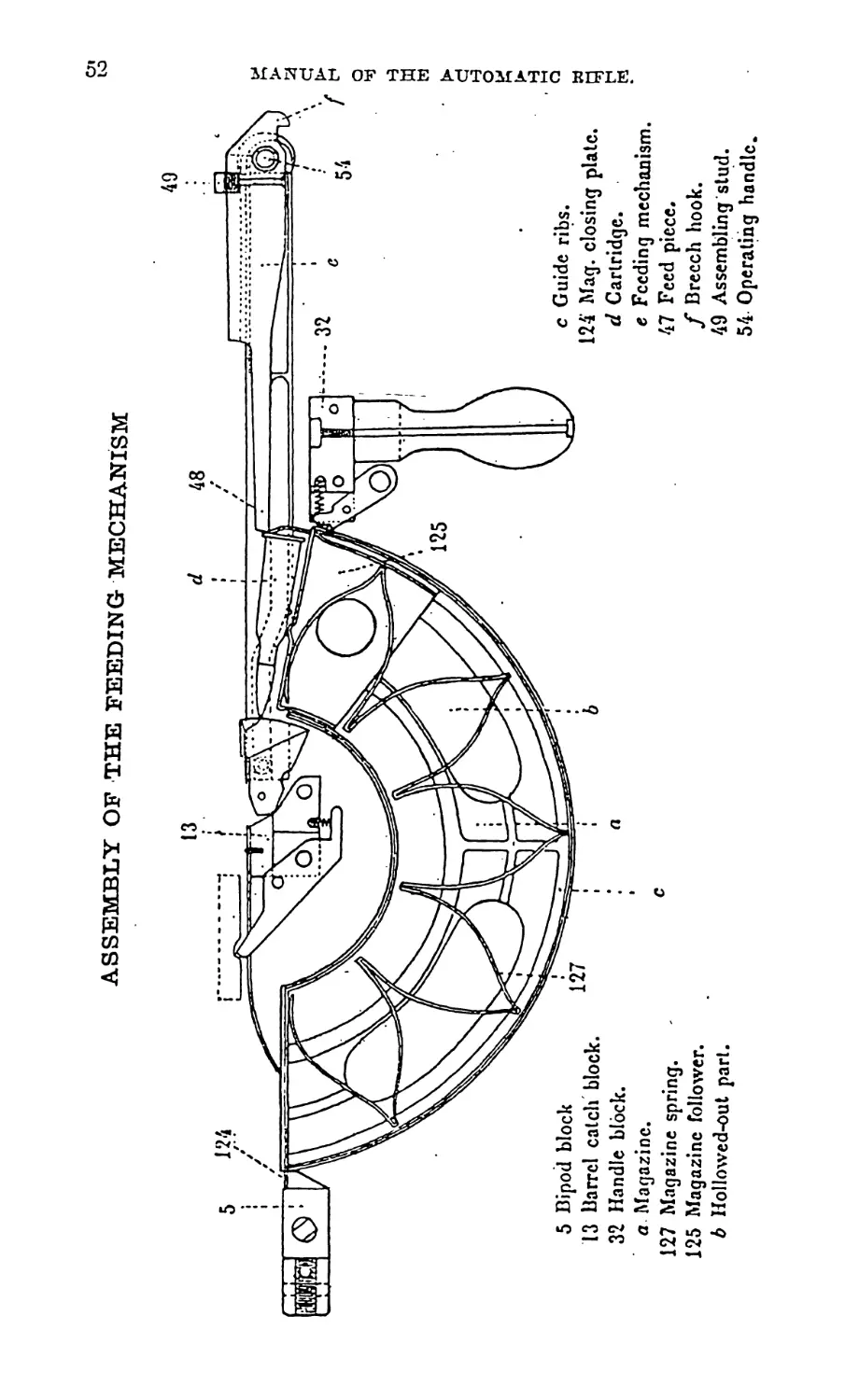
81. The feeding mechanism:
The feeding mechanism includes, the feed piece and the cart-
ridge guide rod.
(a) The feed piece.—Including the arm; the guide ribs of the
feed piece on the breech casing; the sear notch and the operating
handle.
(f>) The cartridge guide rod.—On which are to be seen the S
shaped groove of the roller and the hole for the stem of the operat-
ing handle, which holds the latter and the feed piece together.
Note.—The feeding mechanism is completed by the magazine.
CHAPTER II.
OPERATION OF THE RIFLE.
82. Barrel and bolt motions:
Generalities.—In any automatic rifle, it is necessary to secure
automatically, at a given time, the separation of the barrel and
of the bolt, in order to allow the execution of the different opera-
tions (extraction, ejection, introduction of a new cartridge in the
chamber) indispensible to the working of the gun.
In the automatic rifle, 1915 model, the movable whole (barrel,
bolt) is sent backward by the recoil energy, after which the
barrel is brought back to its firing position by its recoil spring,
while the bolt, held backwards, cannot come back to its first
46
MANUAL OF THE AUTOMATIC EIFLE.
position until the barrel is at its forward position. The separa-
tion of the barrel and of the bolt is then completed.
83. Working: .
To fire, one must cock the bolt mechanism, then hook the
magazine under the rifle, placing the fore extremity between the
bipod block and the radiator housing, and the back extremity on
the magazine catch.
f ; In the barrel and bolt motion of the automatic rifle, 1915
model, three phases must be considered:
First phase: Recoil of.the barrel and the bolt (the two pieces
joined).
Second phase: Return of the barrel to its firing position.
Third phase: Return of the bolt forward.
84. First phase:
Recoil of the barrel and boll (the two pieces joined).
Motive power: The explosion.
One operation: Cocking.
The first shot occurs, the gas acting on the bolt sends it back-
wards. As the bolt is bolted to the barrel, this is sent back-
wards jtoo. The recoil springs are compressed. The movable
breech (and accordingly the firing pin) being at its extreme back-
ward position, the breech recoil spring (acting in this case as
main spring) being compressed, the cocking is effected.
Maintenance of the cocking.—The maintenance of the cocking
is secured by the hooking of the breech hook on the sear head.
85. Second phase:
Return of the barrel to its firing position.
Motive power: Barrel recoil spring.
Four operations:
(1) Withdrawal of the firing pin.
(2) Unlocking.
(3) Extraction.
(4) Ejection.
As soon as the action of the recoil disappears, the barrel recoil
spring sends the barrel forward.
The barrel going forward, forces the bolt head, to which it is
locked, to accompany it.
86. Withdrawal of the firing pin:
The bolt body being held at its backward position by the
hooking of the feed piece on the sear head, only the bolt head can
go forward.
MANUAL OF THE AUTOMATIC BIFLE.
47
The progress of the bolt head (8 mm. long), the length of the
rectilinear part of the working helicoidal grooves, causes the
withdrawal of the firing pin from the hollow face.
The unlocking is not yet finished, since the working lugs move
in the rectilinear part of the helicoidal grooves.
87. Unlocking:
In consequence of the tension caused on the bolt head by the
barrel, whose recoil spring is only incompletely relaxed, working
lugs passing in the helicoidal parts of the bolt body, leave their
bed against the locking shoulders of the breech casing, hence
unlocking.
88. Extraction:
The barrel going on with its run, quits the bolt head. The
cartridge case which was in the barrel being, on the other hand,
detained by the extractor claw, is pulled out of the chamber,
hence extraction.
89. Ejection:
When the distance between the bolt head and the interior
edge of the ejection opening is sufficient, the cartridge case,
pushed by the ejector, pivots around the extractor and is pro-
jected to the right, passing through the ejection opening, hence
ejection.
90. Third phase:
Return of the bolt forward.
Motive power: Bolt recoil spring.
Three operations:
(1) Introduction of a cartridge into the barrel and closing of
the chamber.
(2) Locking.
(3) Firing.
91. Introduction of a cartridge into the barrel and closing of the
chamber:
The barrel being brought back to its firing position, the breech
casing, acting on the firing mechanism, sets free the bolt. Through
the action of the bolt recoil spring, compressed at the time of the
bolt recoil, the latter is sent forward. In this motion, the forward
part of the feed piece arm, meeting a cartridge raised up by the
magazine, pushes it forward and upward in the direction of the
chamber.
The bolt head lower locking lug, acting then on the cartridge,
introduces it into the chamber, hence introduction of a cartridge;
after which the bolt closes the entrance of the cbanberr
48
MANUAL OF THE AUTOMATIC RIFLE.
92. Locking:
At the end of this first operation, the bolt recoil spring is not
completely relaxed. In consequence, it forces the bolt body for-
ward.
As the bolt head is stopped by the cartridge, only the bolt
body can go forward. The bolt body going forward and being
able only to make a rectilinear movement, forces the bolt head
to turn, owing to the-action of the helicoidal grooves on the
working lugs of the bolt head. The locking lugs get in their beds
against the locking shoulders of the breech casing, hence locking.
93. Firing:
The bolt body, going further forward through the action of the
spring, still incompletely relaxed, the working lugs move in the
rectilinear part of the grooves, and the firing pin protrudes in the
hollow case, hence firing.
Remarks.
94. Action of the recoil intensifier:
The front sight is built in such a way as to play the part of
recoil intensifier. For that purpose, it presents internally a
truncated chamber in which the gas expands, when the bullet is
shot out of the barrel.
The gas acting backward on the fore part of the barrel nut,
increases the recoil action it had already caused on the bolt at
the discharge of the first shot.
95. Action of the barrel catch:
When the barrel gets to its firing position, a slight recoil move-
ment on the barrel is to be expected on account of the shock of the
barrel sleeve bushing against the front assembling collar.
The barrel catch stops this motion. Protruding above the
barrel catch block, the nose of the catch, disappearing to allow
the barrel’s passing, pops up again as soon as the latter is at its
firing position, and enters a notch on the bafrel sleeve.
Any movement of the barrel is then impossible.
But, as it is necessary that the barrel should be able to recoil,
the action of the catch must disappear before the discharge of
the shot.
For that purpose, when going forward, the feed piece strikes
the body of the catch, forcing the nose down. The barrel is then
free.
96. Action of the bolt head stop:
The bolt head stop’s function is to keep the bolt/head in the
position “lugs vertical,” when the bolt is sent forward, [For that
MANUAL OF THE AUTOMATIC RIFLE.
49
purpose, the stop has at its lower part a point, which gets into a
notch at the rear part of the bolt head, while the latter is in the
position "lugs vertical.” Any rotation of the bolt head is then
impossible, as the stop, striking the inside of the breech casing,
cannot rise and disengage the bolt head.
But, when the bolt head is practically in touch with the barrel,
it is necessary that the action of the stop should disappear, so as
to allow the freeing of the bolt head which has to turn to lock.
The stop point must at that instant leave its bed in the notch of
the bolt head.
For that purpose, when the bolt head is forced to turn, the
action of the notch’s inclined edges, on the stop point, raises the
latter out of its bed in the bold head. This raising up is possible,
for when the locking occurs, the high part of the stop protrudes
in the ejection opening and is no longer striking the inside of the
breech casing.
97. Firing mechanism:
The automatic rifle, 1915 model, firing mechanism permits
two kinds of firing:
(1) Automatic firing.
(2) Semi-automatic or intermittent firing.
The execution of these two kinds of firing is controlled by the
position given to the safety lock lifter.
98. Automatic firing:
Position of the lifter-horizontal (safety lock at M).
A shot has been fired:
The barrel and bolt recoil together. The bolt is held to the
rear by the sear. As the result of the gunner holding the trigger
to the rear, the trigger bar engaging with the lower end of the
hand sear forces the upper portion of the hand sear forward and
upward. This places the top of the hand sear in the path of the
inclined plane of the breech casing.
Just as the barrel reaches the firing position the inclined plane
strikes the top of the hand sear forcing it down. As the latter is
pivoted to the sear lever, it also forces the sear lever down and
consequently the sear. This releases the bolt which goes for-
ward and fires another shot.
As the barrel again recoils the hand sear is released by the
breech casing. This allows the sear lever to rise due to the force
exerted by the sear spring.
99. Semi-automatic firing:
Position of the lifter—vertical with the eccentric portion
50
MANUAL OF THE AUTOMATIC BIFLE.
facing down. This brings the lifter in contact with the rear part
of the inclined plane on the trigger bar.
Assume that the gun is in a cocked position with the trigger
released:
Pulling the trigger draws the trigger bar to the rear. This
tends to throw the upper part of the hand sear forward, at the
same time raising it. As it cannot rise on account of being in
contact with the breech casing, it forces the sear lever and con-
sequently the sear down, which releases the bolt.
While this action is taking place the trigger bar is forced down
by its inclined plane riding on the lifter until finally the forked
portion at its rear end is forced below the lower arm of the hand
sear and the hand sear returns to its normal position out of the
path of the breech casing.
Before the bolt can again be released it is necessary to release
the trigger so that the fork of the trigger bar can again engage the
lower arm of the hand sear.
100. Safe:
Position of lifter—vertical with the eccentric portion turned
upward.
Safety lock at S:
In this position the lifter is in contact with the lower part of
the sear lever so that the latter cannot be lowered. Therefore,
the sear cannot be depressed and the rifle cannot be fired.
101. Feeding mechanism:
The gun being cocked, insert a full magazine.
The first cartridge, held by the ears of the magazine, is in
the path of the feed piece.
When the trigger is pulled the feed piece striking the upper
portion of the base of the cartridge forces it forward out of the
magazine. The point of the bullet strikes the ramp of the cartridge
guide and is directed ^toward the chamber into which the car-
tridge is finally forced by the bolt head.
The second cartridge is forced up by the magazine spring
against the bottom of the feed piece and rises to the feeding
position against the ears of the magazine, when the mechanism
is recoiled to the rear as the result of the explosion of the first
cartridge.
Note.—In order to provide a clear path for the feed piece the
cartridge guide is lowered by its roller traveling in the groove of
the cartridge guide rod as soon as the cartridge guide has per-
formed its function of directing the bullet end of the cartridge
towards the chamber.
BARREL AND BRE ECH SLEEVE'
30 Recoil spring bushing.
a Flat.
b Slope.
c Guiding groove.
d Ejection opening;
e Locking shoulders.
29 .• Breech.sleeve;
MANUAL OF THE AUTOMATIC KUFLE.
26 Barrel sleeve.
f Circular notch.
27 Barrel sleeve bushing-.
23 Radiator.
24 Barrel nut.
22 Barrel.
cn
ASSEMBLY OF THE FEEDING MECHANISM
127
5 Bipod block
13 Barrel catch block.
32 Handle block.
a Magazine.
127 Magazine spring.
125 Magazine follower.
b Hollowed-oul part.
c Guide ribs.
124 Mag. closing plate.
d Cartridge.
e Feeding mechanism.
47 Feed piece.
f Brecch hook.
49 Assembling slud.
54 Operating handle.
w
13
FEEDING- MECHANISM
48 Feed piece.
MANUAL OF THE AUTOMATIC BIFLE.
£
BOLT HEAD AND BOLT BODY
63
62
46
BOLT HEAD
•• 59
Dolt stem collar.
Boll stem.
Boll body.
47 "Firing pin.
a Firing pin point.
50 Boll head slop.
b Hclicoidal grooves.
c Rectilihcar grooves.
rf Hole for the first introduction of the slop.
e Working lug grooves.
f Slop seal.
(7 Lug.
MANUAL OF THE AUTOMATIC RIFLE.
58 Extractor spring.
56 Extractor.
h Extractor claw.
i Hollow face.
59 Ejector.
19 Ejector spring.
59 a Ejector screw.
k .Locking lugs.
I Boll head rcinforcer.
m Scat of the firing pin.
n Bed of the carrier assembling slud,
о Bed of the carrier. ,
FIRING MECHANISM
MANUAL OF THE AUTOMATIC BIFLE.
BLOCKS
13 Barre catch block.
15 Cartridge guide.
(I Ramp.
e Roller axle.
fj Barrel lever pin.
A Nose.
i Body.
20 Barrel catch spring.
18 Magazine stop spring
32 Handle block.
40 Handle.
18
38 Handle stem.
39 Handle nul.
5 Bipod block.
a Threading.
b Front swivel hole.
c Magazine front support plane.
8 Front assembling bolt.
33 Magazine catch.
35 Magazine catch handle.
36 Magazine catch spring.
34 Magazine catch pin.
MANUAL OF THE AUTOMATIC RIFLE.
RECEIVER SIDEPLATES
MANUAL OF THE AUTOMATIC RIFLE.
ж
4 Plug.
a Notch.
b Threading.
60 Spring guide tube.
1 Breech housing’.
3 Assembling collar, rear.
c Ejection opening.
HOUSING
S
28
25
d Rear sight.
2 Assembling collar front,
e Assembling clasp.,
28 Radiator housing.
f Threading.
25 Front sight.
<7 Threading.
MANUAL OF THE AUTOMATIC BUTE.
AUTOMATIC RIFLE, MODEL 1915 (CHAUCHAT)
’ manual of the automatic klfle.
FITTINGS
11 Sling swivel boll.
11 я Sling swivel bolt.
12 Sling swivel pin.
a Threading.
MANUAL OF THE AUTOMATIC RIFLE.
62
MANUAL OF THE AUTOMATIC RIFLE.
SAFETY LOCK
POSITION OF THE LIFTER
3
H'l
1 ’ ’5 5
(g''2X) Q-......................................5'
2 4 6
1 Round by round firing.
2 Lifter vertical and turned downwards
3 Automatic firing.
4 Lifter horizontal.
5 Safety.
6 Lifter vertical and turned upwards.
CHAPTER III.
102. Stoppages of the Chauchat automatic rifle:
The word stoppage is used as being more comprehensive than
jam, which has been used quite generally in our service to desig-
nate not only jams, properly speaking, but also cessations of fire
due to any mal-functioning of the rifle, to broken parts or to de-
fective ammunition.
Experience has proved that a strict observance of the correct
firing position diminishes considerably the number of stoppages.
Automatic firing is obtained by means of fixed and mobile points.
The stability must be absolute. The stability ceases to exist
when the firer does not hold his weapon firmly. The expansion of
the gas and the recoil springs do not bear the same relation, and
the result is a stoppage.
Some stoppages which occurred with the first models have
been corrected since modifications have been made in certain
parts and the steel tempered differently. The following were
causes of these stoppages:
(1) Broken bolt head stop.
(2) Broken toe of barrel catch.
(3) Broken ejector.
(4) Play between the housing and side plates.
MANUAL OF THE AUTOMATIC BIFLE.
63
103. The following are the st
Chaucfaat now in service:
Stopp
During the first phase of the
operation of the gun (recoil of
the barrel and bolt)............
During the 2nd phase (return of
the barrel to its firing posi-
tion)—..........................
During the 3rd phase (return of
the bolt forward)...............
In the firing mechanism...
104. Failure of sear notch to ею
Cause:
(a) Friction in the barrel and
breech casing or fouled gun.
(6) Insufficient quantity or poor
quality of the powder.
(c) Gas escapes between the
barrel nut and the radiator
casing.
Effects: Insufficient recoil of th
Situation: The sear notch not
the movable whole returns, the en
and there is a stoppage.
>ppages which happen with the
tges.
1. Failure to engage the sear
notch with the sear.
2. Exaggerated elevation of the
barrel catch.
3. Non return of the barrel.
4. Failure to extract.
5. Failure to eject.
6. Failure to feed.
7. Bad presentation of a cart-
ridge.
8. Misfire.
9. The safety lock being set
for single shots the rifle
fires automatically.
10. The safety lock being set
at safe, the rifle fires.
11. Safety lock being set for
single shots, the rifle will
not fire at all. Fires auto-
matically, functioning well.
12. The rifle will not fire when
safety lock is set either for
single shots or auto-
matically.
;age sear:
Remedy:
Work on by mechanic.
Clean the gun.
New ammunition.
Change barrel nut—mechanic.
; barrel and the bolt.
engaging the head of the sear,
ipty cartridge case is not ejected
MANUAL OF THE AUTOMATIC RIFLE.
To continue firing, cock the gun.
The friction is very often due to the friction of the cartridge
guide against the-breech casing. It is due to a bad position of
the cartridge guide rod in the cartridge guide rod guide; the roller
being still- in the curve of the groove of the cartridge guide rod,
when the cartridge guide comes in contact with the breech casing,
resulting in a strong pressure when the roller has to pass in the
elevated part of the groove.
105. Exaggerated elevation of the nose of the barrel catch:
Causes: Remedy:
The wearing out or bending of Exchange or straighten the pin.
the pin of the barrel catch
by striking against the bar-
rel catch block.
Effect: The barrel catch, under the action of its spring, is ele-
vated too high.
Situation: The nose of the catch presses against the radiator,
which chips out the aluminum and fouls the breech housing and
guide. This may cause a failure of the sear notch to engage with
the sear or non-return of the barrel.
106. Non-return of the barrel:
Causes:
(a) Difficult extraction.
Defective cartridge.
(5) Difficult unbolting.
Fouling.
(c) Weakness of barrel recoil
spring.
(d) Friction of the barrel and
breech casing in the housing,
or against the cartridge
guide.
Fouling.
Remedy:
Cleaning.
New spring.
Work of mechanic—see the
regulating of the cartridge
guide rod guide under 1.
Cleaning.
Effect: Non-return of the barrel and a stoppage occurs.
Situation: In the first two cases the barrel is retained in its
rear position by the sear notch engaged with the sear; in the
other two cases the barrel does not completely return to its for-
ward position. The cartridge case remains in the barrel. Work
the operating handle to cause the barrel to go to its forward posi-
tion. If that is not sufficient, knock the butt of the gun against the
ground, first putting the safety lock at safe.
MANUAL OF THE AUTOMATIC BIFLE. ‘ .65
(<l)
(ft)
(c)
107. Failure to extract: ,:
Causes: Remedy:
Fouling of the chamber. Cleaning.
Defective ammunition, head •
of shell too thick.
Broken extractor claw. Change extractor.
Effect: The head of the cartridge has not been engaged by the
extractor.
Situation: The barrel has returned to its firing position with an
empty shell in the chamber. To extract that shell use the hand
extractor, or rod which is in the cleaning kit.
108. Failure to eject:
Causes:
(a) Ejector spring is weak.
(6) Extractor spring weak.
(c) Extractor claw worn.
Remedy:
New spring.
New spring.
New extractor—work of me-
chanic.
Effect: The shell instead of being projected through the ejec-
tion opening, falls back in the breech casing.
Situation: When the bolt goes forward it is stopped by this
empty shell.
109. Failure to feed:
Cause:
(a) Dirty magazine.
Remedy:
Exchange the magazine with-
out losing time.
(6) Weak magazine spring.
(c) Magazine plates deformed.
Effect: The follower does not rise; the feed piece does not find
a cartridge in its path.
Situation: Stoppage with bolt closed, no cartridge in the
chamber.
110. Bad presentation of the shell in the direction of the chamber:
Causes:
(a) Defective magazine (cars too
wide).
(b) Insufficient elevation of fol-
lower.
(c) Insufficient elevation of the
cartridge guide.
Remedy:
Change magazine.
Change magazine.
Regulate the cartridge guide
rod guide.
66 MANUAL. OF THE AUTOMATIC BIFLE.
Effect: The cartridge, pushed by the feed piece arm, strikes
against the high part of the breech casing in the first case; in the
second case, under the sloping part of the cartridge guide; in the
third case, between the breech casing and the cartridge guide.
Situation: Stoppage. The bolt, which is not completely locked,
stopped in the first case by the pushing of the lower part of the
bolt head against the body of the ‘cartridge case; in the other
cases by the pushing of the feed piece arm against the head of
the shell.
111. The safety lock set for single shots, the rifle fires auto-
matically:
Cause:
(1) Worn lifter or worn inclined plane of the triggar bar.
Effect: The lifter does not push the bar down sufficiently.
(2) Play in the safety lock axle (see par. 113).
Effect: The lifter, instead of acting on the bar, is elevated by
the bar.
Situation: In both cases, the toe of the bar remains in contact
with the arm of the hand sear, and therefore prevents the pivoting
of the hand sear, whose head comes in contact with the ramp of
the breech casing.
Remedy: Exchange the worn part.
(Defective ammimition, insufficient quantity or poor quality
of powder are able to produce automatic fire when the safety lock
is set for single shots. In this case the sear notch does not engage
the sear but the feed piece arm may have passed over the head of
the cartridge which is in the magazine and pushed it forward
when the bolt returns forward. The resistance of the head of the
cartridge at this moment is sufficient to produce a separation of
the barrel and bolt and to permit, therefore, the ejection of the
shell and the introduction of new shell and the discharge.)
112. The safety lock set at safe, the rifle fires:
Cause: Remedy:
Too much play in the safety lock New safety lock,
axle.
Effect: The lifter, instead of stopping the depression of the
sear lever, is itself pushed down by this lever.
Situation: The sear lever, not being blocked, pushes on the
sear and disengages the sear notch.
MANUAL OF THE AUTOMATIC EIFLE. 67
113. The safety lock set for single shots, the rifle does not fire.
Set for automatic fire, fires well:
Cause: Remedy:
Inclined plane of trigger bar File the inclined plane of the
too thick. bar or the lifter slightly.
Effect: Premature lowering of the trigger bar.
Situation: In firing single shots, the toe of the bar does not
maintain contact long enough with the arm of the hand sear, and
therefore does not act on the mechanism. In the automatic firing,
the inclined plane not acting at all, the gun functions well.
114. The rifle will fire neither by single shots nor automatically:
Cause: Remedy:
Play in the axle of the trigger, of Exchange the worn parts,
the sear and of the sear lever
in their tubes.
Effect: The two fixed points of the firing mechanism are out
of place.
Situation: The axle head of the sear and the body of the sear
lever receive in part the pressure which should be at the point or
contact of lever and sear. For this reason the sear head is not
lowered sufficiently to allow the freeing of the sear notch.
115. Breaking of parts:
The following are the causes of broken parts:
(a) Excessive gas pressure.
(&) Premature firing.
The break always occurs at the weak part of the piece and is
often due to defects in the steel.
116. Excessive gas pressure:
(1) Broken recoil spring bushing.
(2) Broken operating handle.
(3) Broken feed piece.
(4) Broken assembling stud.
The barrel and breech casing are projected backward too
violently. The operating handle strikes the rear part of the
opening in the side plate. This shock which is increased by the
weight of the cartridge guide rod is the cause of the broken parts
given above.
68 MANUAL OF THE AUTOMATIC BIFLE.
The breaking of the bushing is due to its striking the handle of
the plug.
It is necessary in case of a broken operating handle 'to be very
careful in handling the weapon, as the following cases may be
presented:
(a) When the bolt goes forward, the cartridge guide rod is
freed from the axle of the operating handle, but its forward end is
always engaged in the cartridge guide rod guide, consequently
the cartridge guide is held in an elevated position and the intro-
duction of a cartridge is possible.
The feed piece arm moving forward presses on the cartridge
which is in the magazine; the lower lug of the bolt head pushes
the cartridge, but the introduction has not been completed,
because the mechanism of the bolt has been stopped by the feed
piece arm encountering the cartridge guide in an elevated position.
There is a jam, and half of the cartridge is visible. If in any
way the cartridge guide rod is freed from the guide, the least shock
permits the bolt to go forward, under the action of the barrel
recoil spring, forcing the cartridge guide to lower. The arm thus
plays the role of the cartridge guide rod.
The bolt mechanism, being connected with the feeding mechan-
ism, the bolting is produced and the cartridge fired.
(Z>) The operating handle may not be completely broken by
the shock mentioned above and may still follow the feed piece
and cartridge guide rod when the bolt, under the action of the bolt
recoil spring, goes forward. ’ During that movement, a cartridge
under the pressure of the feed piece arm is pushed in the direction
of the chamber.
If at this moment it is still in contact with the cartridge guide,
the operating handle, after its last strain, is then broken, the
cartridge guide rod is immobilized. The part of the axle, which
remains on the feed piece, jams the feed piece against the cartridge
guide rod; the bolt is stopped; the introduction of the cartridge
into the chamber is not completed, and the cartridge is visible
through the ejection opening. Under these conditions a very
slight shock will cause the bolt to go forward and a shot will be
fired.
117. Premature firing (Defective ammunition):
(1) Broken breech casing.
(2) Broken extractor.
If the primer projects beyond the cartridge head, the discharge
takes place at the moment of the introduction of the cartridge
MANUAL OF THE AUTOMATIC BIFLE.
69
by the shock of the force of the bolt head. The head of the ex-
tractor is frequently broken,*.and_ the breech casing, after ex-
panding, is broken.
,’^Note: This breaking of the Lbreechjcasing might happen on
account of play of the locking lugs between the locking grooves
and the locking shoulders. The locking shoulders sustain a
great blow at the moment of discharge, and repeated shocks cause
the break which takes place between the forward end of the
ejection opening and the groove in front of the right locking
shoulder. In this case, replace the bolt head or the same trouble
will occur again.
118. Care of the Chauchat and of the magazine:
The stoppages due to the rifle itself are few. The weapon can
not be blamed if the ammunition is defective, if the rifle is not
cared for, or the gunner is inexperienced. Weapons are of value
only when in the hands of well instructed and disciplined men.
Experienced gun crews are unanimous in the praise of the service
given by this weapon. The troops that have reported unfavor-
ably upon the weapon are those whose gun crews were without
sufficient training and discipline at the time of combat.
CHAPTER IV.
DISMOUNTING AND ASSEMBLING OF THE RIFLE.
119. To strip the Chauchat automatic rifle:
(1) Unscrew plug; remove recoil springs and bushing.
(2) Take weight off bipodband turn front assembling bolt
down; disengage rear assembling bolt from stud.
(3) Remove the housing from the receiver.
(4) Remove feed piece.
(5) Withdraw bolt and remove bolt head from the bolt body.
(6) Withdraw the barrel and breech casing from the housing.
120. To assemble the Chauchat automatic rifle:
(1) Insert barrel and breech casing in the housing.
(2) Assemble the complete bolt and insert in the breech
casing.
(3) Place feed piece on bolt body.
(4)jPush rear assembling bolt to the right.
(5) Place housing on the receiver.
(6) Draw cartridge guide rod to the rear.
.(7) Seat front assembling clasp and turn up front assembling
bolt.
70
MANUAL OF THE AUTOMATIC RIFLE.
' (S) Elevate cartridge guide; insert cartridge guide rod in its
guide and push the rod forward.
(9) Seat the rear assembling stud and secure rear assembling
bolt.
(10) Place recoil springs and bushing on the spring tube; screw-
in the plug.
Note.—Never dismount the pieces composing the receiver or
fixed on it (blocks, trigger mechanism). These pieces, difficult to
get together, are fixed to the brackets by screw bolts so that a re-
peated unscrewing would wear them out and their loss would so be
f acilitated.
The cleaning does not necessitate the dismounting of these
pieces.
CHAPTER V.
CARE OF THE RIFLE AND OF THE MAGAZINE.
121. Rifle:
The rifle must be kept in the best state of preservation. After
each firing it must be cleaned and oiled, using for that purpose
good lubricating oil, if possible, sperm oil.
The use of kerosene helps considerably in the cleaning of the
very fouled parts, but it is necessary to wipe carefully after using
it and before greasing, otherwise all the parts put in kerosene
would easily oxidize.
In the automatic rifle, 1915 model, the part that gets dirty,
generally, is the barrel nut, especially after a long firing. It will
be necessary thoroughly to clean this part of the rifle.
The rifle being dismounted, wipe all the pieces thoroughly with
a dry rag. Sponge the housing carefully, taking care to clean
perfectly the interior of the front sight. Pass the rag inside of
barrel and oil abundantly.
Be sure of the cleanliness of the breech casing, especially at
its fore part and at the rear edge of the barrel; the support should-
ers of the bolt head lugs must be in a perfect state of preservation.
Use a soft wooden scraper.
The cleaning of the barrel nut must be done in the following
manner: soak the nut in kerosene, scrape lightly, taking care not
to whiten the metal.
It must be remembered that any dismounting of the blocks
and of the fitting system is forbidden. For cleaning, use the rag
and the scraper.
MANUAL OF THE AUTOMATIC BIFLE.
In case of attack by gas, oil entirely and abundantly with
sperm oil. It gives a six hour£ preservation.
122. Magazines:
(a) The magazine is part of the feeding mechanism. Con-
sequently, it must be kept in a perfect state of preservation.
After each firing, the magazines must be completely and properly
oiled.
(ft) The gunners must take care of the state of the spring of
each magazine.
To be good, the spring must, when it is taken out of the maga-
zine, have the shape of an incompletely closed crown.
The interruption between the two ends of the spring must not
exceed four fingers.
In case of greater spacing, increase the spring’s strength by
opening with the hand, the angles having the vertex on the internal
circumference of the crown.
If in spite of this operation, the spring remains weak, it must
be replaced.
123. Outfit:
The outfit of the automatic rifle, 1915 model, is placed in a
small cleaning kit which is carried inside the musette.
The outfit carried in this kit is:
One three pieced cleaning rod.
One barrel brush.
One patch section.
One housing and breech casing sponge.
One defective cartridge extractor.
One hand extractor.
One oil can.
One kerosene can.
CHAPTER VI.
124. Cartridges:
The automatic rifle, 1915 model, uses the cartridge 18S6 D.
model (with modified priming) placed eighteen in,a magazine.
125. Magazines:
The magazine is made out of sheet steel. Its shape is that of
a segment of a circle. It is composed of two side plates and two
bottom plates forming a box. One of the side plates is solid, the
other is bored through allowing a view of the internal part of the
magazine.
12 MANUAL OF THE AUTOMATIC RIFLE.
Ribs secure the stiffness of the magazines and the guiding of
the cartridges.-^
One of the ends is closed with a plate (used as a support for the
spring). The nose of the plate protruding externally from the
magazine is used to fasten the magazine on the receiver. The
other end is open to permit the passing of the cartridges.
Two ears extending from the side plates make it impossible
for the cartridges to come out from the magazine unless they are
forced to do so by'pressure on the cartridge base.
Inside of the magazine, there is a follower whose part is to
push the cartridges continuously toward the hole.
This follower is moved by a double bow spring having its
immovable support on the magazine closing plate.
126. Loading of the magazine:
To load the magazine: lower the follower with the hand, a’
distance equal to the thickness of the cartridge.
Engage a cartridge, the base first, let it lie down on the follower;
lower this one anew and go on with tKe loading, lowering pro-
gressively the follower, so as to permit the passing of the cart-
ridge to be engaged. The magazine is filled when it contains
twenty cartridges (IS gives the best result).
To empty a magazine: push gradually on the base of the cart-
ridges in the same manner the feed piece arm would do in the
operation of the rifle.
Note.—It will be found advantageous not to keep the maga-
zines filled without necessity, so as not to strain the spring.
127. Seating of the magazine on the rifle:
To seat the magazine on the rifle: cock the rifle, seize the
magazine with the right hand, and curve"downward, the follower
backward.
Place the closing plate, the nose directed upward, between the
bipod block and the barrel catch block. Then force the magazine
home until it ’engages the magazine catch.
To disengage the magazine, bring the operating handle to
extreme backward position, to secure the hooking of the bolt.
Press forward the handle of the magazine, catch, and take off
the magazine with the hand. The magazine would, without this
precaution, fall down by itself, under the action of the magazins
stop spring.
I. Breech booalag.
X Asoombtag collar. front,
X Asaembliag collar. roar,
4. Plug.
X Bipod block,
8. Sian plato-right,
7. Std.plaUdJt,
8. Asoombliag bolt, front,
8A. Aenomblizg bolt, rear.
X Assembling bolt washer. front.
10. Aseemblk^ not.
11. Sling swivel bolt,
11A. Sling swivel,
17. Sling swivel pin.
13. Barrel catch block.
14. Cartridge guide rod guiib,
IS. Cartridge guide,
19. Cartridge guide bolt,
17. Magarino stop spring screw,
13. Magazine stop spring,
10. Barrel catch,
20. Barrel cakb spring.
31. Cartridge guide rod.
21 A. Cartridge guide roller,
22. Band,
23. Radiator,
Barrel nut.
Front right.
Barrel sleeve.
Barrel sleeve bushing.
Radiator housing.
Handle block.
Mag arise catch.
Banal catch and mngasino catch pin,
Magarino catch hnmlle.
Magarino catch spring.
Side plate screw.
Hamllo stem,
Handle nut.
Handle.
Assembling bolt ami xifcty lock nnu,
Arm atop.
Arm knob.
Assembling boll latch, roar.
Boll head.
Bolt body.
Firing pin,
Food piece.
Assembly stud.
50. Balt head stop,
51. Sear spring,
53. Assembling bolt latch pin.
54. Operating handle.
55. Assembling bolt spring washer.
55. Estractor,
57. Extractor pin,
55. Extractor spring.
59. Elector.
59Л. Ejector screw,
80. Spring guide tube.
81. Spring guide Cube plug.
61. Bolt stem,
83. Bolt stem collar,
84. Spring guide tube pin,
85. Bolt stem pin.
00. Bolt atom collar pin,
87. Bolt recoil spring,
68. Grip plate, right,
89. Grip plate, loft,
69A. Grip plate, bottom,
70. Trigger guard,
71. Trigger bar spring atud,
72. Sear spring rivet,
73. Grip block,
74. Grip, right.
75.
78
80.
81.
S3.
81.
S3.
80.
87.
89.
00.
WA.
01.
02.
94.
10).
101.
103.
104.
105.
100.
107.
Grip. left.
Grip Lolu
Grip bolt eat.
Trigger.
Ejector spring,
Bushing.
Sear,
Trigger bar,
Trigger bar pin.
Trigger bar spring.
Hand sear.
Hand sear pin.
Sear lover.
Plug latch.
Plug latch handle.
Plug latch spring.
Safety lock.
Scar spring tvnshcr.
Stock,
Stock plate.
Assembling boll bushing, rear,
Stock bolt,
Trigger guard «crew.
Bipod bond.
Bipod leg top,
108. Bipod log пегом,
109. Bipod log foot.
110. Bipod log.
111. Rear eight basu.
112. Rear eight base screw.
113. Roar eight leaf.
114. Roar sight leal pin.
115. Rear sight slide,
118. Roar sight slide catch,
117. Itaar sight slide cutch opting,
118. Roar sight notch plate.
П9. Roar sight aotoh plate screw,
120. Roar sight bate spring,
121. Roar sight base spring screw.
13*3. Blagariao side, mala.
123. Magarino aldo, female.
124. Magarino closing plate.
125. Mngaxlno follower,
127. Maga>mo spring,
123. Flash screen coupling.
130. Flash screen.
130. Assembling bolt Intermediate washer, front.