/


Tags: weapons military affairs
Year: 1918


Text
SCHOOL of AUTOMATIC ARMS
40th Division, Camp Kearny, Cal.
NOTES ON MECHANISM OF THE CHAUCHAT
MACHINE RIFLE, MODEL 1915
FEBRUARY 1918
Machine Gun Instruction and Inspection Division,
Ordnance Depot, 40th Division.
PREFACE
In the following notes it has been attempted to set forth in logical order
for purposes of instruction, all available material pertaining to the me-
chanism of the Chauchat Machine Rifle, Model 1915. Advantage has been
taken of the valuable material contained in the French Pamphlet "Le Fusil
Mitrailleur” of the Fourth Army School at Chalons-sur-Marne.
PERSONNEL OF THE AUTOMATIC RIFLE TEAM
Each rifle team consists of three men: One gunner, and two carriers.
The three men should have the same proficiency in handling the rifle so as to
be able to take the place of any one in case he has been put out of action.
The man handling the gun must be able to keep the gun in action without
the aid of the other two.
Duties of each man:
1. Gunner: He should keep cool, conserve his supply of ammunition,
and keep his eye on the objective at all times, in other words, to be master
of the situation, in order to produce the greatest effect.
2. First Carrier: Carries the gunner’s pouch, takes up his position at
the right of the gunner, and watches the functioning of the gun, and aids
the gunner to keep the rifle in action. He should be proficient in rapidly
handing the full magazine to the gunner after he has taken the empty one
from him. It is his duty to reload magazines from his ammunition supply.
3. Second Carrier: Takes up his position to the right of the first
carrier and acts as a defense either with his rifle or his bayonet and protects
the other two men during stoppages and changes of magazines. He keeps
the first carrier supplied with full magazines and when a supply of loaded
magazines have been exhausted he gives single rounds to the first carrier
from his cartridge belt.
Method of Cleaning During Action:
All the men of the automatic rifle section must be experts in quick
cleaning the rifle during a lull in action so as to keep it in good condition
and always in use. The platoon leaders supervises the cleaning of the rifles
being sure that half the rifles are always in action. Each gunner reports
to the platoon leader when his gun needs cleaning. In this way the platoon
leader can keep track of his gun and see that they are not all being cleaned
at the same time. Each gunner should be trained to follow a correct
method of dismounting so as to facilitate rapidity of cleaning.
In training the men in cleaning the rifle, practice should be given them
in dismounting and cleaning under different conditions, and at unexpected
times and places, so as to familiarize them and simulate as nearly as possible,
actual conditions under which they will have to do this work.
The gunner and the first carrier do all the cleaning, W’hile the second
carrier armed with a rifle acts as a defense for the rest of the team. The
gunner and first carrier obscure themselves from the enemy and protect
themselves from rifle fire by means of simple fortifications, if necessary.
After having arranged themselves with sufficient protection, they proceed
in the following manner.
The gunner unscrews the spring guide cap; the first carrier gets out his
cleaning kit, oil can, cleaning rod and patches, and arranges them to be
easily accessable, to the gunner or himself. The gunner removes the spring
tube, recoil spring bushing, mainspring, recoil spring, feed piece and bolt
mechanism and hands them to the first carrier to be cleaned. He then re-
moves the barrel and breech casing from the housing, places them in such
a position so as to be cooled. He then cleans the rifle carriage and housing
The first carrier having cleaned the parts given to him, now cleans the barrel,
it having had time to cool. Experience have showm that this method of the
distribution of the parts for cleaning have proven the most efficient, keeping
both men busy at all times, and completing their vzork at the same time.
The first carrier having oiled the parts, returns them to the gunner who
assembles the gun in the reverse order in which it was taken dowm. The
first carrier aids the gunner in mounting the housing on the carriage, and
flocking the rear assembling bolt and the front assembling bolt. While the
first carrier is collecting his cleaning material and replacing them in the
pouch the gunner replaces the spring tube and springs.
COMBAT EQUIPMENT OF ONE TEAM
Corpora!
Rifle and bayonet, four full magazines in a bag, fifty-six single rounds
in cartridge belt (Seven packages of eight cartridges each). Total 136
rounds.
Gunner
Revolver with three full clips, four full magazines in a bag, two pockets
on belt containinT two full magazines each, pick shovel. Total 160 rounds.
1st. Carrier
Revolver with three full clips, eight full magazines and a bag, one pack
containing eight packages of eight cartridges each and eight full magazines
in pack, shovel. Total 384 rounds.
2nd. Carrier
Rifle and bayonet, twelve full magazines in pack, sixty-four single rounds
in cartridge belt, shovel. Total 304 rounds.
Total ammunition carried by team 848 rounds, exclusive of the ammuni-
tion carried by the corporal.
Note:
The ammunition carried by the corporal is for both teams in his squad,
he supplying the team most in need of ammunition.
Nomenclature
The parts of the rifle are divided into two classes, fixed and movable.
The movable parts are those which are put into action by the natural
recoil of the barrel on the rearward stroke and by the recoil spring and
mainspring on the forward stroke. The fixed parts are those which direct
and guide the correct functioning of the movable parts. Numbers in
parenthesis refer to numbers on plate.
FIXED PARTS
I. Housing (breech housing and radiator casing). (1 and 28)
II. Rifle Carriage.
III. Grip Mechanism.
IV. Bipod.
I. Housing.
1. Flash screen (129)
2. Flash screen coupling (128)
3. Front sight (25)
4. Radiator casing (28)
5. Connector bushing, front (2)
6. Breech housing (1)
7. Rear sight
(a) Rear sight base (111)
(b) Rear sight base screw (112)
(c) Rear sight leaf (113)
(d) Rear sight leaf pin (114)
(e) Rear sight slide (115)
(f) Rear sight slide catch (116)
(g) Rear sight slide catch spring (117)
(h) Rear sight notch plate (118)
(i) Rear sight notch plate screw (119)
(i) Rear sight base spring (120)
(k) Rear sight base spring screw (121)
8. Connector bushing, rear (3)
9. Spring tube (60)
(a) Spring tube plug (61)
(b) Spring guide cap (4)
(c) Spring tube cap pin (64)
II. Rifle Carriage.
1. Side plate, right (6)
2. Side plate, left (7)
Side plate screws (37)
4. Bipod block (5)
5. Front assembling bolt (8)
(a) Front assembling bolt washer (9)
(b) Front assembling bolt arm (41)
(c) Bolt arm knob (43)
(d) Bolt arm stop (42)
4
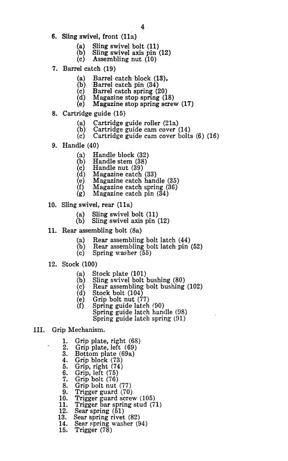
6. Sling swivel, front (Ila)
(a) Sling swivel bolt (11)
(b) Sling swivel axis pin (12)
(c) Assembling nut (10)
7. Barrel catch (19)
(a) Barrel catch block (13),
(b) Barrel catch pin (34)
(c) Barrel catch spring (20)
(d) Magazine stop spring (18)
(e) Magazine stop spring screw (17)
8. Cartridge guide (15)
(a) Cartridge guide roller (21a)
(b) Cartridge guide cam cover (14)
(c) Cartridge guide cam cover bolts (6) (16)
9. Handle (40)
(a) Handle block (32)
(b) Handle stem (38)
(c) Handle nut (39)
(d) Magazine catch (33)
(e) Magazine catch handle (35)
(f) Magazine catch spring (36)
(g) Magazine catch pin (34)
10. Sling swivel, rear (11a)
(a) Sling swivel bolt (11)
(b) Sling swivel axis pin (12)
11. Rear assembling bolt (8a)
(a) Rear assembling bolt latch (44)
(b) Rear assembling bolt latch pin (52)
(c) Spring washer (55)
12. Stock (100)
(a) Stock plate (101)
(b) Sling swivel bolt bushing (80)
(c) Rear assembling bolt bushing (102)
(d) Stock bolt (104)
(e) Grip bolt nut (77)
(f) Spring guide latch <90)
Spring guide latch handle (98)
Spring guide latch spring (91)
III. Grip Mechanism.
1. Grip plate, right (68)
2. Grip plate, left (69)
3. Bottom plate (69a)
4. Grip block (73)
5. Grip, right (74)
6. Grip, left (75)
7. Grip bolt (76)
8. Grip bolt nut (77)
9. Trigger guard (70)
10. Trigger guard screw (105)
11. Trigger bar spring stud (71)
12. Sear spring (51)
13. Sear spring rivet (82)
14. Sear spring washer (94)
15. Trigger (78)
5
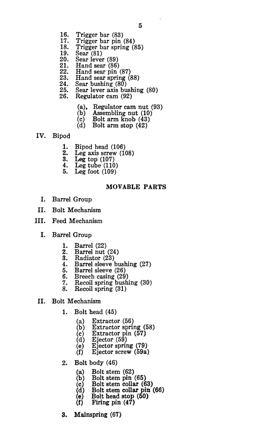
16. Trigger bar (83)
17. Trigger bar pin (84)
18. Trigger bar spring (85)
19. Sear (81)
20. Sear lever (89)
21. Hand sear (86)
22. Hand sear pin (87)
23. Hand sear spring (88)
24. Sear bushing (80)
25. Sear lever axis bushing (80)
26. Regulator cam (92)
(a)» Regulator cam nut (93)
(b) Assembling nut (10)
(c) Bolt arm knob (43)
(d) Bolt arm stop (42)
IV. Bipod
1. Bipod head (106)
2. Leg axis screw (108)
3. Leg top (107)
4. Leg tube (110)
5. Leg foot (109)
MOVABLE PARTS
I. Barrel Group
II. Bolt Mechanism
III. Feed Mechanism
I. Barrel Group
1. Barrel (22)
2. Barrel nut (24)
3. Radiator (23)
4. Barrel sleeve bushing (27)
5. Barrel sleeve (26)
6. Breech casing (29)
7. Recoil spring bushing (30)
8. Recoil spring (31)
II. Bolt Mechanism
1. Bolt head (45)
(a) Extractor (56)
(b) Extractor spring (58)
(c) Extractor pin (57)
(d) Ejector (59)
(e) Ejector spring (79)
(f) Ejector screw (59a)
2. Bolt body (46)
(a) Bolt stem (62)
(b) Bolt stem pin (65)
(c) Bolt stem collar (63)
(d) Bolt stem collar pin (66)
(e) Bolt head stop (50)
(f) Firing pin (47)
3. Mainspring (67)
6
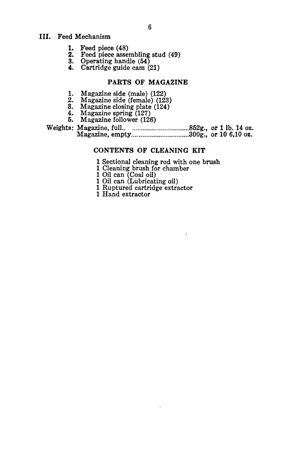
III. Feed Mechanism
1. Feed piece (48)
2. Feed piece assembling stud (49)
3. Operating handle (54)
4. Cartridge guide cam (21)
PARTS OF MAGAZINE
1. Magazine side (male) (122)
2. Magazine side (female) (123)
3. Magazine closing plate (124)
4. Magazine spring (127)
5. Magazine follower (126)
Weights: Magazine, full...............852g., or 1 lb. 14 oz.
Magazine, empty...............300g., or 10 6,10 oz.
CONTENTS OF CLEANING KIT
1 Sectional cleaning rod with one brush
1 Cleaning brush for chamber
1 Oil can (Coal oil)
1 Oil can (Lubricating oil)
1 Ruptured cartridge extractor
1 Hand extractor
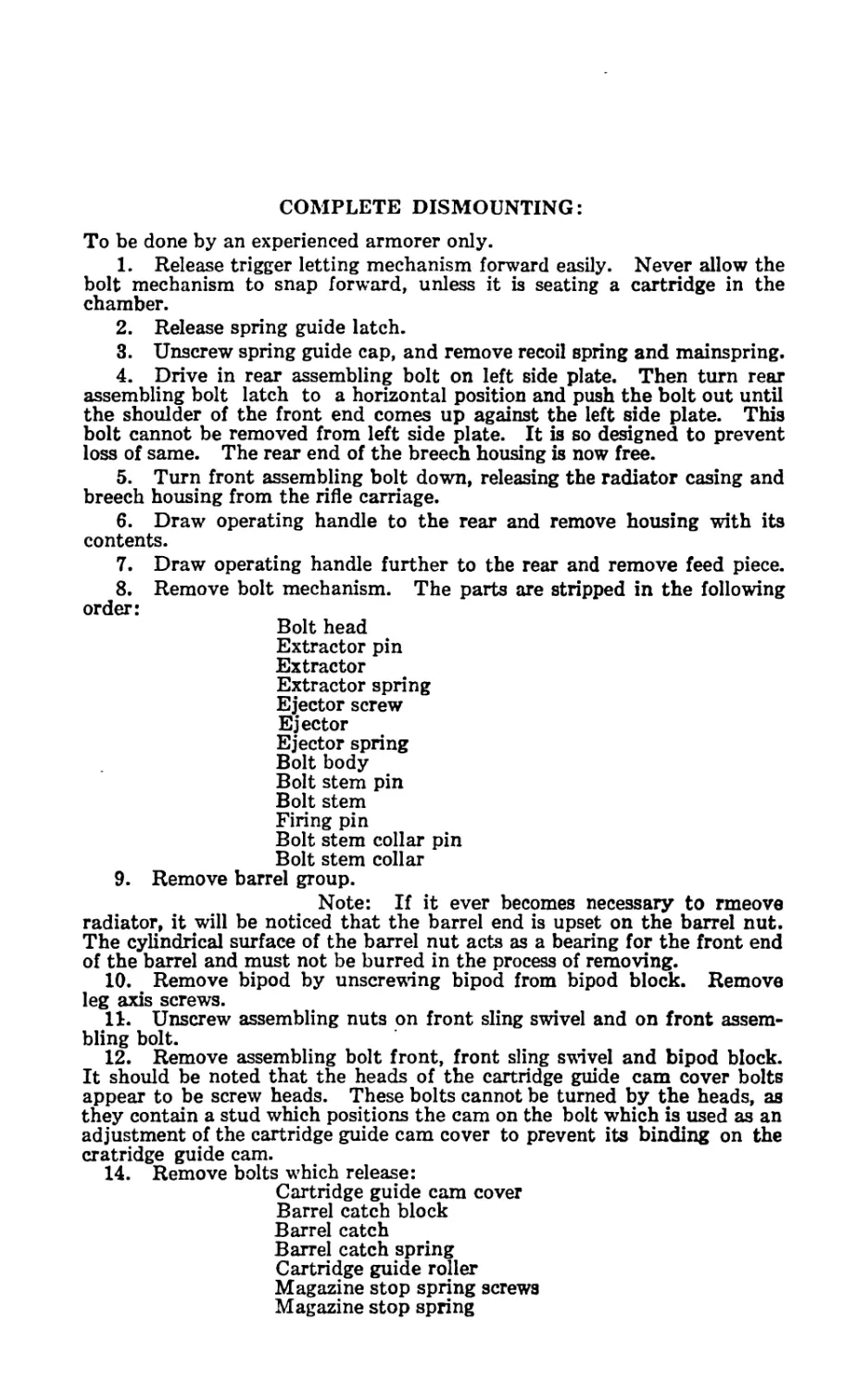
COMPLETE DISMOUNTING:
To be done by an experienced armorer only.
1. Release trigger letting mechanism forward easily. Never allow the
bolt mechanism to snap forward, unless it is seating a cartridge in the
chamber.
2. Release spring guide latch.
3. Unscrew spring guide cap, and remove recoil spring and mainspring.
4. Drive in rear assembling bolt on left side plate. Then turn rear
assembling bolt latch to a horizontal position and push the bolt out until
the shoulder of the front end comes up against the left side plate. This
bolt cannot be removed from left side plate. It is so designed to prevent
loss of same. The rear end of the breech housing is now free.
5. Turn front assembling bolt down, releasing the radiator casing and
breech housing from the rifle carriage.
6. Draw operating handle to the rear and remove housing with its
contents.
7. Draw operating handle further to the rear and remove feed piece.
8. Remove bolt mechanism. The parts are stripped in the following
order:
Bolt head
Extractor pin
Extractor
Extractor spring
Ejector screw
Ejector
Ejector spring
Bolt body
Bolt stem pin
Bolt stem
Firing pin
Bolt stem collar pin
Bolt stem collar
9. Remove barrel group.
Note: If it ever becomes necessary to rmeove
radiator, it will be noticed that the barrel end is upset on the barrel nut.
The cylindrical surface of the barrel nut acts as a bearing for the front end
of the barrel and must not be burred in the process of removing.
10. Remove bipod by unscrewing bipod from bipod block. Remove
leg axis screws.
11. Unscrew assembling nuts on front sling swivel and on front assem-
bling bolt.
12. Remove assembling bolt front, front sling swivel and bipod block.
It should be noted that the heads of the cartridge guide cam cover bolts
appear to be screw heads. These bolts cannot be turned by the heads, as
they contain a stud which positions the cam on the bolt which is used as an
adjustment of the cartridge guide cam cover to prevent its binding on the
cratridge guide cam.
14. Remove bolts which release:
Cartridge guide cam cover
Barrel catch block
Barrel catch
Barrel catch spring
Cartridge guide roller
Magazine stop spring screws
Magazine stop spring
8
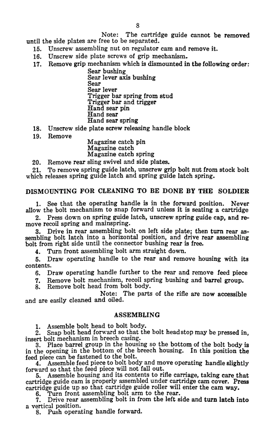
Note: The cartridge guide cannot be removed
until the side plates are free to be separated.
15. Unscrew assembling nut on regulator cam and remove it.
16. Unscrew side plate screws of grip mechanism.
17. Remove grip mechanism which is dismounted in the following order:
Sear bushing
Sear lever axis bushing
Sear
Sear lever
Trigger bar spring from stud
Trigger bar and trigger
Hand sear pin
Hand sear
Hand sear spring
18. Unscrew side plate screw releasing handle block
19. Remove
Magazine catch pin
Magazine catch
Magazine catch spring
20. Remove rear sling swivel and side plates.
21. To remove spring guide latch, unscrew grip bolt nut from stock bolt
which releases spring guide latch and spring guide latch spring.
DISMOUNTING FOR CLEANING TO BE DONE BY THE SOLDIER
1. See that the operating handle is in the forward position. Never
allow the bolt mechanism to snap forward unless it is seating a cartridge
2. Press down on spring guide latch, unscrew spring guide cap, and re-
move recoil spring and mainspring.
3. Drive in rear assembling bolt on left side plate; then turn rear as-
sembling bolt latch into a horizontal position, and drive rear assembling
bolt from right side until the connector bushing rear is free.
4. Turn front assembling bolt arm straight down.
5. Draw operating handle to the rear and remove housing with its
contents.
6. Draw operating handle further to the rear and remove feed piece
7. Remove bolt mechanism, recoil spring bushing and barrel group.
8. Remove bolt head from bolt body.
Note: The parts of the rifle are now accessible
and are easily cleaned and oiled.
ASSEMBLING
1. Assemble bolt head to bolt body.
2. Snap bolt head forward so that the bolt head stop may be pressed in,
insert bolt mechanism in breech casing.
3. Place barrel group in the housing so the bottom of the bolt body is
in the opening in the bottom of the breech housing. In this position the
feed piece can be fastened to the bolt.
4. Assemble feed piece to bolt body and move operating handle slightly
forward so that the feed piece will not fall out.
5. Assemble housing and its contents to rifle carriage, taking care that
cartridge guide cam is properly assembled under cartridge cam cover. Press
cartridge guide up so that cartridge guide roller will enter the cam way.
6. Turn front assembling bolt arm to the rear.
7. Drive rear assembling bolt in from the left side and turn latch into
a vertical position.
8. Push operating handle forward.
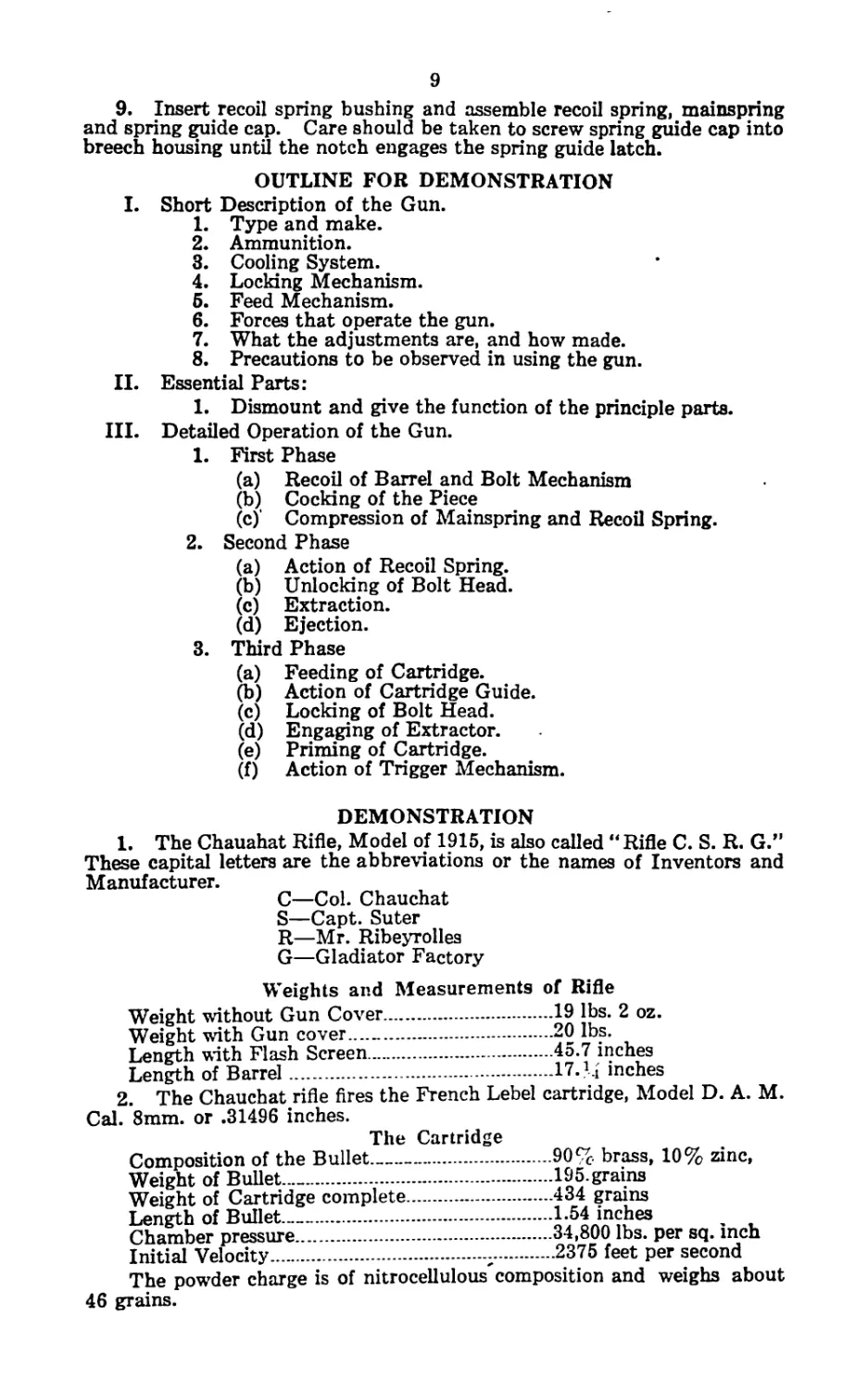
9
9. Insert recoil spring bushing and assemble recoil spring, mainspring
and spring guide cap. Care should be taken to screw spring guide cap into
breech housing until the notch engages the spring guide latch.
OUTLINE FOR DEMONSTRATION
I. Short Description of the Gun.
1. Type and make.
2. Ammunition.
3. Cooling System.
4. Locking Mechanism.
6. Feed Mechanism.
6. Forces that operate the gun.
7. What the adjustments are, and how made.
8. Precautions to be observed in using the gun.
II. Essential Parts:
1. Dismount and give the function of the principle parts.
III. Detailed Operation of the Gun.
1. First Phase
(a) Recoil of Barrel and Bolt Mechanism
(b) Cocking of the Piece
(c) Compression of Mainspring and Recoil Spring.
2. Second Phase
(a) Action of Recoil Spring.
(b) Unlocking of Bolt Head.
(c) Extraction.
(d) Ejection.
3. Third Phase
(a) Feeding of Cartridge.
(b) Action of Cartridge Guide.
(c) Locking of Bolt Head.
(d) Engaging of Extractor.
(e) Priming of Cartridge.
(f) Action of Trigger Mechanism.
DEMONSTRATION
1. The Chauahat Rifle, Model of 1915, is also called “Rifle C. S. R. G.”
These capital letters are the abbreviations or the names of Inventors and
Manufacturer.
C—Col. Chauchat
S—Capt. Suter
R—Mr. Ribeyrolles
G—Gladiator Factory
Weights and Measurements of Rifle
Weight without Gun Cover..................19 lbs. 2 oz.
Weight with Gun cover.....................20 lbs.
Length with Flash Screen..................45.7 inches
Length of Barrel..........................17. M inches
2. The Chauchat rifle fires the French Lebel cartridge, Model D. A. M.
Cal. 8mm. or .31496 inches.
The Cartridge
Composition of the Bullet...............90% brass, 10% zinc,
Weight of Bullet...»......................195.grains
Weight of Cartridge complete..............434 grains
Length of Bullet—.........................1.54 inches
Chamber pressure.........................34,800 lbs. per sq. inch
Initial Velocity.........................2375 feet per second
The powder charge is of nitrocellulous composition and weighs about
46 grains.
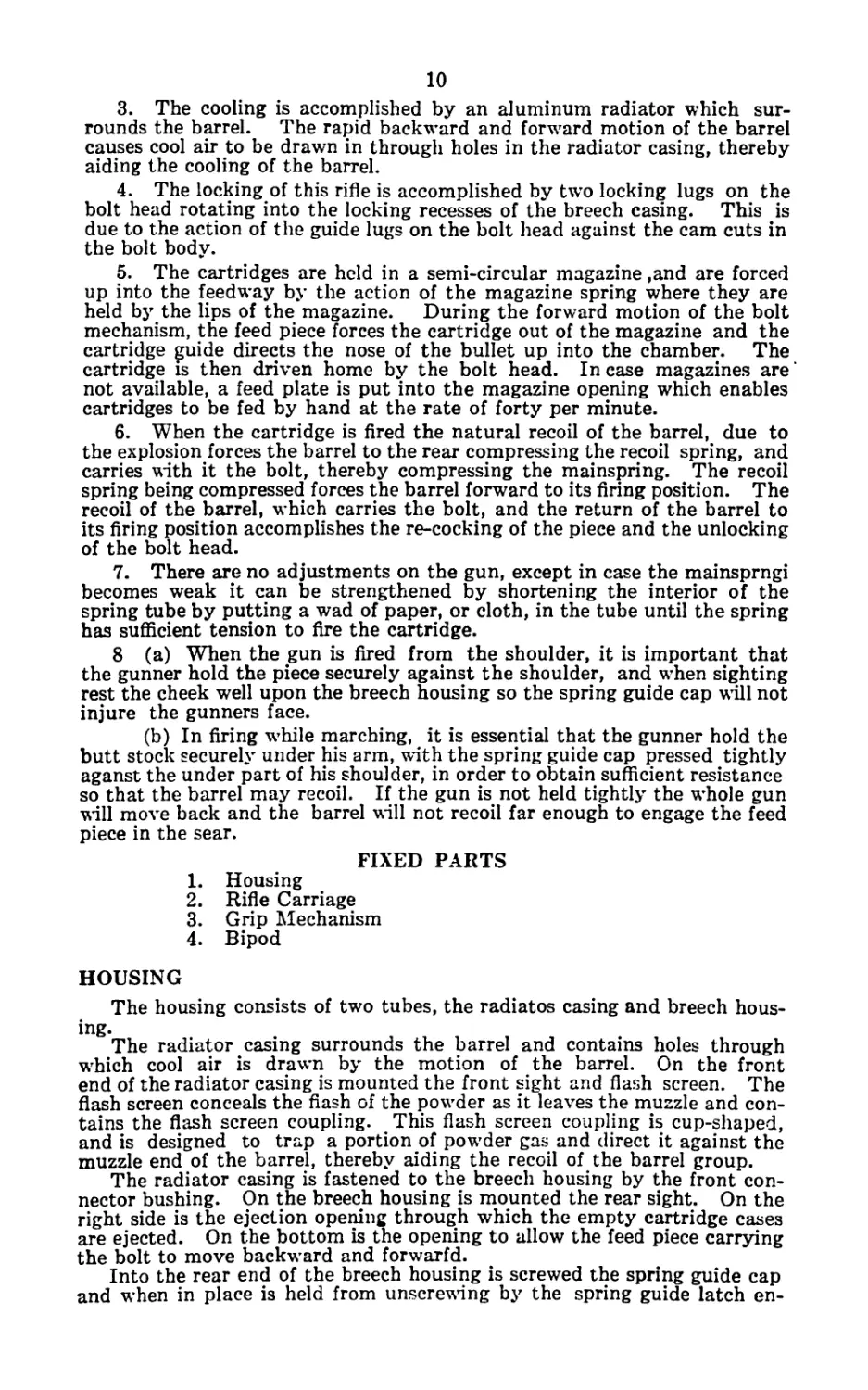
10
3. The cooling is accomplished by an aluminum radiator which sur-
rounds the barrel. The rapid backward and forward motion of the barrel
causes cool air to be drawn in through holes in the radiator casing, thereby
aiding the cooling of the barrel.
4. The locking of this rifle is accomplished by two locking lugs on the
bolt head rotating into the locking recesses of the breech casing. This is
due to the action of the guide lugs on the bolt head against the cam cuts in
the bolt body.
5. The cartridges are held in a semi-circular magazine ,and are forced
up into the feedway by the action of the magazine spring where they are
held by the lips of the magazine. During the forward motion of the bolt
mechanism, the feed piece forces the cartridge out of the magazine and the
cartridge guide directs the nose of the bullet up into the chamber. The
cartridge is then driven home by the bolt head. In case magazines are
not available, a feed plate is put into the magazine opening which enables
cartridges to be fed by hand at the rate of forty per minute.
6. When the cartridge is fired the natural recoil of the barrel, due to
the explosion forces the barrel to the rear compressing the recoil spring, and
carries with it the bolt, thereby compressing the mainspring. The recoil
spring being compressed forces the barrel forward to its firing position. The
recoil of the barrel, which carries the bolt, and the return of the barrel to
its firing position accomplishes the re-cocking of the piece and the unlocking
of the bolt head.
7. There are no adjustments on the gun, except in case the mainsprngi
becomes weak it can be strengthened by shortening the interior of the
spring tube by putting a wad of paper, or cloth, in the tube until the spring
has sufficient tension to fire the cartridge.
8 (a) When the gun is fired from the shoulder, it is important that
the gunner hold the piece securely against the shoulder, and when sighting
rest the cheek well upon the breech housing so the spring guide cap will not
injure the gunners face.
(b) In firing while marching, it is essential that the gunner hold the
butt stock securely under his arm, with the spring guide cap pressed tightly
aganst the under part of his shoulder, in order to obtain sufficient resistance
so that the barrel may recoil. If the gun is not held tightly the whole gun
will move back and the barrel will not recoil far enough to engage the feed
piece in the sear.
FIXED PARTS
1. Housing
2. Rifle Carriage
3. Grip Mechanism
4. Bipod
HOUSING
The housing consists of two tubes, the radiatos casing and breech hous-
ing.
The radiator casing surrounds the barrel and contains holes through
which cool air is drawn by the motion of the barrel. On the front
end of the radiator casing is mounted the front sight and flash screen. The
flash screen conceals the flash of the powder as it leaves the muzzle and con-
tains the flash screen coupling. This flash screen coupling is cup-shaped,
and is designed to trap a portion of powder gas and direct it against the
muzzle end of the barrel, thereby aiding the recoil of the barrel group.
The radiator casing is fastened to the breech housing by the front con-
nector bushing. On the breech housing is mounted the rear sight. On the
right side is the ejection opening through which the empty cartridge cases
are ejected. On the bottom is the opening to allow the feed piece carrying
the bolt to move backward and forwarfd.
Into the rear end of the breech housing is screwed the spring guide cap
and when in place is held from unscrewing by the spring guide latch en-
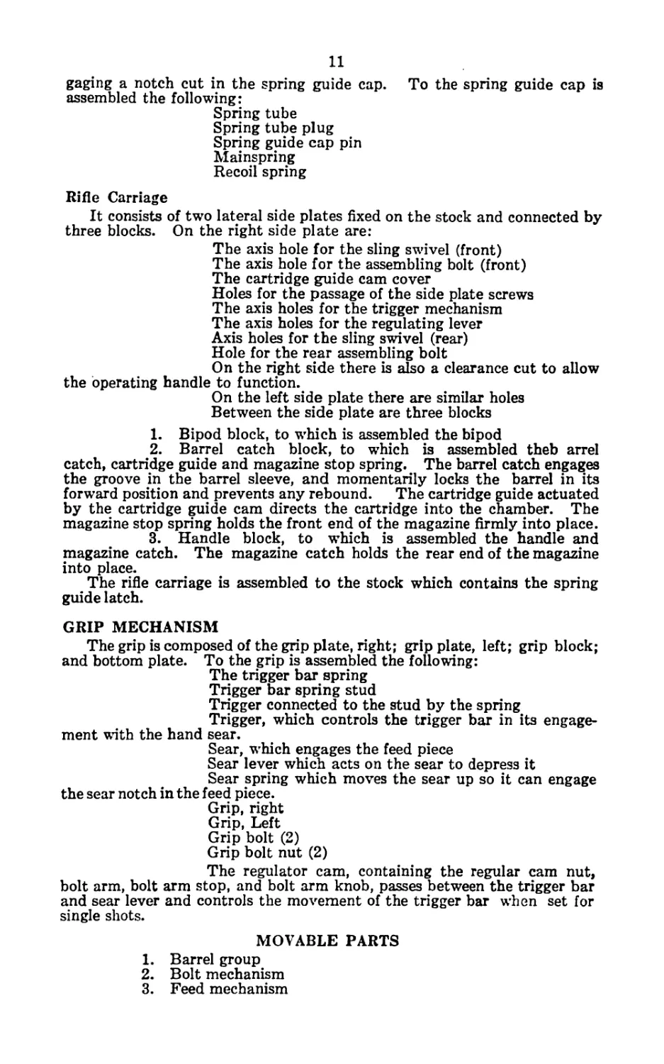
11
gaging a notch cut in the spring guide cap. To the spring guide cap is
assembled the following:
Spring tube
Spring tube plug
Spring guide cap pin
Mainspring
Recoil spring
Rifle Carriage
It consists of two lateral side plates fixed on the stock and connected by
three blocks. On the right side plate are:
The axis hole for the sling swivel (front)
The axis hole for the assembling bolt (front)
The cartridge guide cam cover
Holes for the passage of the side plate screws
The axis holes for the trigger mechanism
The axis holes for the regulating lever
Axis holes for the sling swivel (rear)
Hole for the rear assembling bolt
On the right side there is also a clearance cut to allow
the operating handle to function.
On the left side plate there are similar holes
Between the side plate are three blocks
1. Bipod block, to which is assembled the bipod
2. Barrel catch block, to which is assembled theb arrel
catch, cartridge guide and magazine stop spring. The barrel catch engages
the groove in the barrel sleeve, and momentarily locks the barrel in its
forward position and prevents any rebound. The cartridge guide actuated
by the cartridge guide cam directs the cartridge into the chamber. The
magazine stop spring holds the front end of the magazine firmly into place.
3. Handle block, to which is assembled the handle and
magazine catch. The magazine catch holds the rear end of the magazine
into place.
The rifle carriage is assembled to the stock which contains the spring
guide latch.
GRIP MECHANISM
The grip is composed of the grip plate, right; grip plate, left; grip block;
and bottom plate. To the grip is assembled the following:
The trigger bar spring
Trigger bar spring stud
Trigger connected to the stud by the spring
Trigger, which controls the trigger bar in its engage-
ment with the hand sear.
Sear, which engages the feed piece
Sear lever which acts on the sear to depress it
Sear spring which moves the sear up so it can engage
the sear notch in the feed piece.
Grip, right
Grip, Left
Grip bolt (2)
Grip bolt nut (2)
The regulator cam, containing the regular cam nut,
bolt arm, bolt arm stop, and bolt arm knob, passes between the trigger bar
and sear lever and controls the movement of the trigger bar when set for
single shots.
MOVABLE PARTS
1. Barrel group
2. Bolt mechanism
3. Feed mechanism
12
Barrel group
Starting at the muzzle end of the barrel are the following;
Barrel nut
Radiator which surrounds the barrel
Barrel sleeve bushing
Barrel sleeve, on which is cut the groove to engage the
barrel catch.
Breech casing, in which is the locking recess for the
bolt head, the ejection opening through which the empty shells are thrown
out, and on the bottom is a clearance cut in which the feed piece travels.
On the rear end of the breech casing is noticed a ramp which on the forward
motion of the barrel acts on the hand sear depressing it, thereby releasing
the bolt mechanism.
Recoil spring bushing, which acts as a seat for the
recoil spring.
Recoil spring which furnishes the power to drive the
barrel forward.
Bolt Mechanism
Bolt head on which is the extractor and extractor spring
fastened to it by the extractor pin. On the front end of the bolt head are
the locking lugs which fit into the locking recess in the breech casing. Near
the rear end of the bolt head are the guide lugs, which act in the cam cuts
in the bolt body and direct the rotary motion of the bolt head. At the ex-
treme rear end of the bolt head is a seat into which the bolt head stop drops
and prevents any backward or rotary motion of the bolt head.
Bolt body on which is mounted the bolt stem and firing
pin. It also contains the cam cuts which control the locking and unlocking
of the bolt head. On the bolt stem is the bolt stem collar which acts as a
seat for the mainspring.
Feed Mechanism
The feed piece containing grooves to fit the cuts in the bot-
tom of the bolt body and the feed piece assembling stud which fastens the
bolt body to the feed piece.
On the rear end of the feed piece is the sear notch
which engages the sear and holds the bolt mechanism in its rearward posi-
tion.
The cartridge guide cams which actuates the cartridge
guide by means of the cartridge guide roller.
The operating handle for cocking the piece.
Magazine
Near the rear end of the magazine is a hole through the
side plates into which the bullet end of a cartridge can be put to hold back
the magazine follower while the magazine is being filled.
On the rear end of the magazine is the notch which
holds the magazine in place by means of the magazine catch.
On the top of the rear end of the magazine the sides
are turned over forming lips which are so designed to place the cartridge in
position to be moved forward out of the magazine into the chamber.
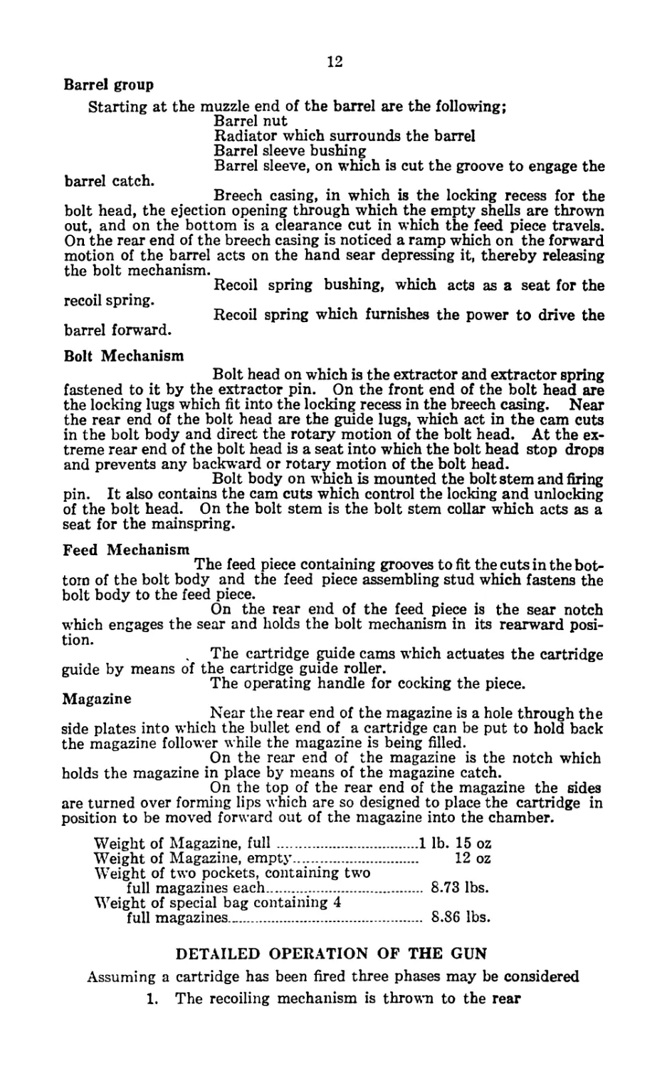
Weight of Magazine, full...................1 lb. 15 oz
Weight of Magazine, empty..................... 12 oz
Weight of two pockets, containing two
full magazines each........................ 8.73 lbs.
Weight of special bag containing 4
full magazines........................... 8.86 lbs.
DETAILED OPERATION OF THE GUN
Assuming a cartridge has been fired three phases may be considered
1. The recoiling mechanism is thrown to the rear
13
2. The barrel is moved forward under the tension of the
recoil spring to its firing position.
3. The bolt mechanism is moved forward under the tension
of the mainspring
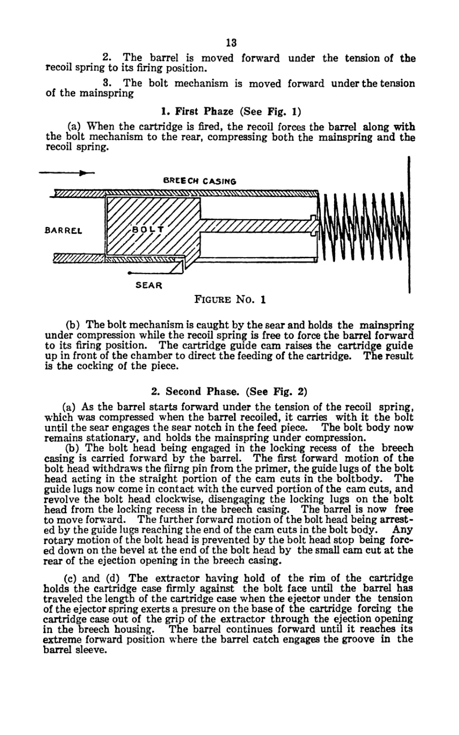
1. First Phaze (See Fig. 1)
(a) When the cartridge is fired, the recoil forces the barrel along with
the bolt mechanism to the rear, compressing both the mainspring and the
recoil spring.
BREECH CASING
SEAR
Figure No. 1
(b) The bolt mechanism is caught by the sear and holds the mainspring
under compression while the recoil spring is free to force the barrel forward
to its firing position. The cartridge guide cam raises the cartridge guide
up in front of the chamber to direct the feeding of the cartridge. The result
is the cocking of the piece.
2. Second Phase. (See Fig. 2)
(a) As the barrel starts forward under the tension of the recoil spring,
which was compressed when the barrel recoiled, it carries with it the bolt
until the sear engages the sear notch in the feed piece. The bolt body now
remains stationary, and holds the mainspring under compression.
(b) The bolt head being engaged in the locking recess of the breech
casing is carried forward by the barrel. The first forward motion of the
bolt head withdraws the fiirng pin from the primer, the guide lugs of the bolt
head acting in the straight portion of the cam cuts in the boltbody. The
guide lugs now come in contact with the curved portion of the cam cuts, and
revolve the bolt head clockwise, disengaging the locking lugs on the bolt
head from the locking recess in the breech casing. The barrel is now free
to move forward. The further forward motion of the bolt head being arrest-
ed by the guide lugs reaching the end of the cam cuts in the bolt body. Any
rotary motion of the bolt head is prevented by the bolt head stop being forc-
ed down on the bevel at the end of the bolt head by the small cam cut at the
rear of the ejection opening in the breech casing.
(c) and (d) The extractor having hold of the rim of the cartridge
holds the cartridge case firmly against the bolt face until the barrel has
traveled the length of the cartridge case when the ejector under the tension
of the ejector spring exerts a presure on the base of the cartridge forcing the
cartridge case out of the grip of the extractor through the ejection opening
in the breech housing. The barrel continues forward until it reaches its
extreme forward position where the barrel catch engages the groove in the
barrel sleeve.
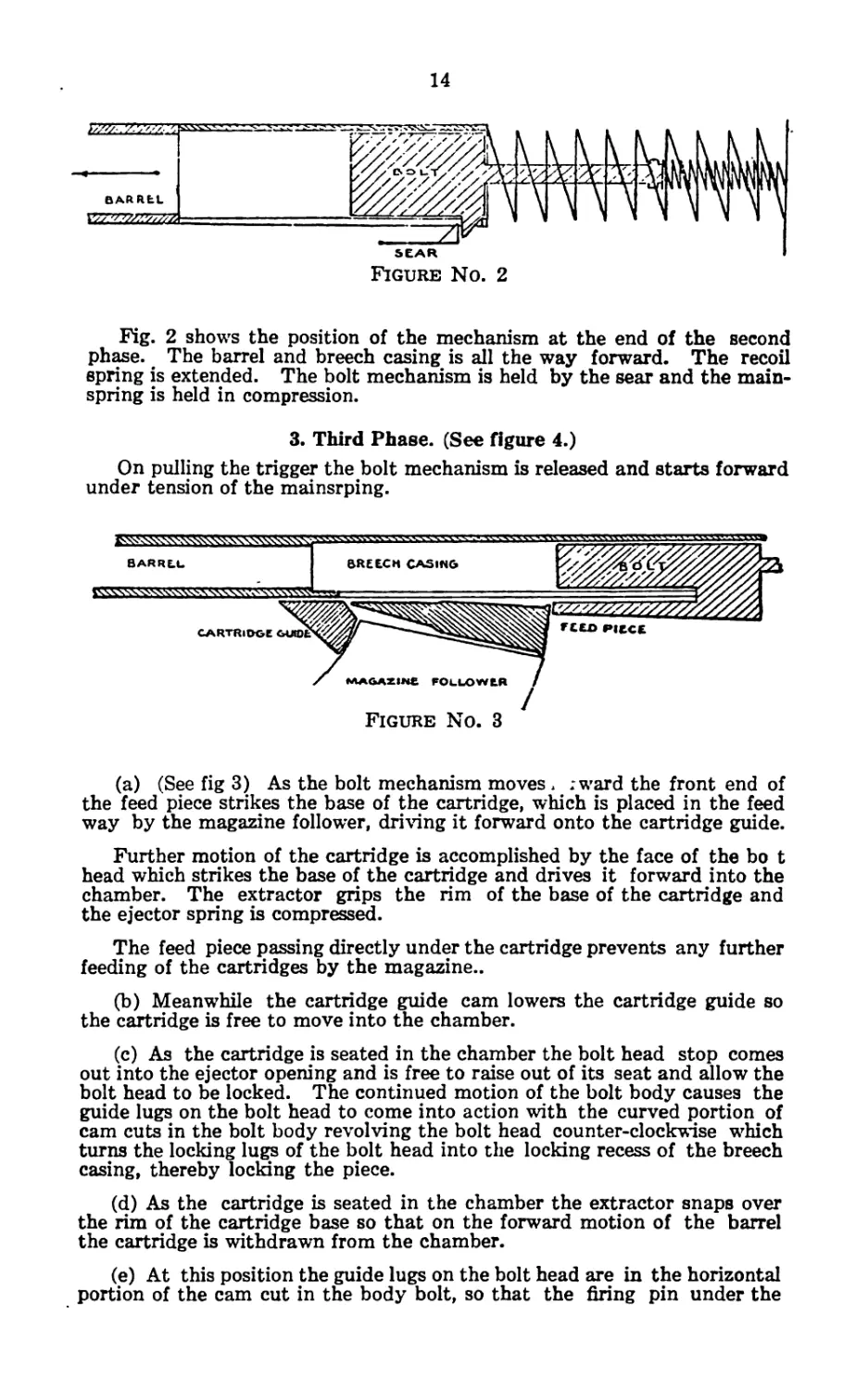
14
SEAR
Figure No. 2
Fig. 2 shows the position of the mechanism at the end of the second
phase. The barrel and breech casing is all the way forward. The recoil
spring is extended. The bolt mechanism is held by the sear and the main-
spring is held in compression.
3. Third Phase. (See figure 4.)
On pulling the trigger the bolt mechanism is released and starts forward
under tension of the mainsrping.
(a) (See fig 3) As the bolt mechanism moves > ;ward the front end of
the feed piece strikes the base of the cartridge, which is placed in the feed
way by the magazine follower, driving it forward onto the cartridge guide.
Further motion of the cartridge is accomplished by the face of the bo t
head which strikes the base of the cartridge and drives it forward into the
chamber. The extractor grips the rim of the base of the cartridge and
the ejector spring is compressed.
The feed piece passing directly under the cartridge prevents any further
feeding of the cartridges by the magazine..
(b) Meanwhile the cartridge guide cam lowers the cartridge guide so
the cartridge is free to move into the chamber.
(c) As the cartridge is seated in the chamber the bolt head stop comes
out into the ejector opening and is free to raise out of its seat and allow the
bolt head to be locked. The continued motion of the bolt body causes the
guide lugs on the bolt head to come into action with the curved portion of
cam cuts in the bolt body revolving the bolt head counter-clockwise which
turns the locking lugs of the bolt head into the locking recess of the breech
casing, thereby loclang the piece.
(d) As the cartridge is seated in the chamber the extractor snaps over
the rim of the cartridge base so that on the forward motion of the barrel
the cartridge is withdrawn from the chamber.
(e) At this position the guide lugs on the bolt head are in the horizontal
portion of the cam cut in the body bolt, so that the firing pin under the
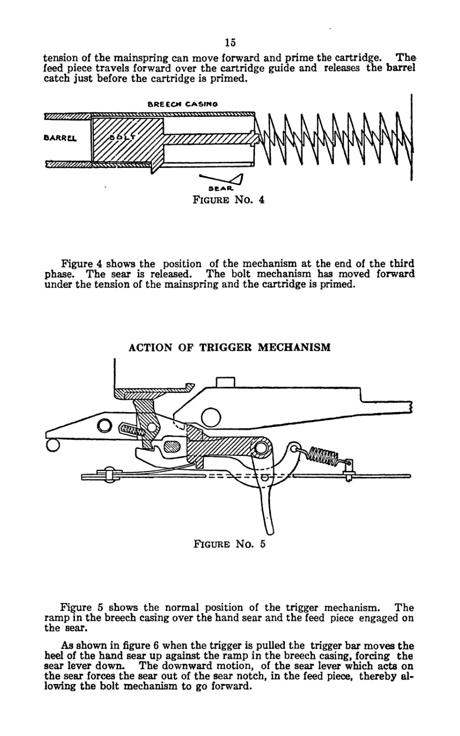
15
tension of the mainspring can move forward and prime the cartridge. The
feed piece travels forward over the cartridge guide and releases the barrel
Figure 4 shows the position of the mechanism at the end of the third
phase. The sear is released. The bolt mechanism has moved forward
under the tension of the mainspring and the cartridge is primed.
ACTION OF TRIGGER MECHANISM
Figure No. 5
Figure 5 shows the normal position of the trigger mechanism. The
ramp in the breech casing over the hand sear and the feed piece engaged on
the sear.
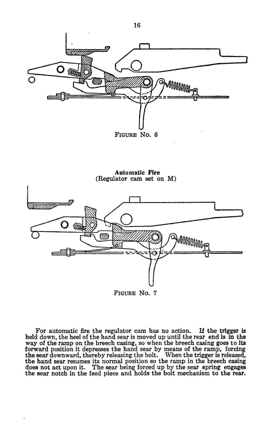
As shown in figure 6 when the trigger is pulled the trigger bar moves the
heel of the hand sear up against the ramp in the breech casing, forcing the
sear lever down. The downward motion, of the sear lever which acts on
the sear forces the sear out of the sear notch, in the feed piece, thereby al-
lowing the bolt mechanism to go forward.
16
Automatic Fire
(Regulator cam set on M)
Figure No. 7
For automatic fire the regulator cam has no action. If the trigger is
held down, the heel of the hand sear is moved up until the rear end is in the
way of the ramp on the breech casing, so when the breech casing goes to its
forward position it depresses the hand sear by means of the ramp, forcing
the sear downward, thereby releasing the bolt. When the trigger is released,
the hand sear resumes its normal position so the ramp in the breech casing
does not act upon it. The sear being forced up by the sear spring engages
the sear notch in the feed piece and holds the bolt mechanism to the rear.
17
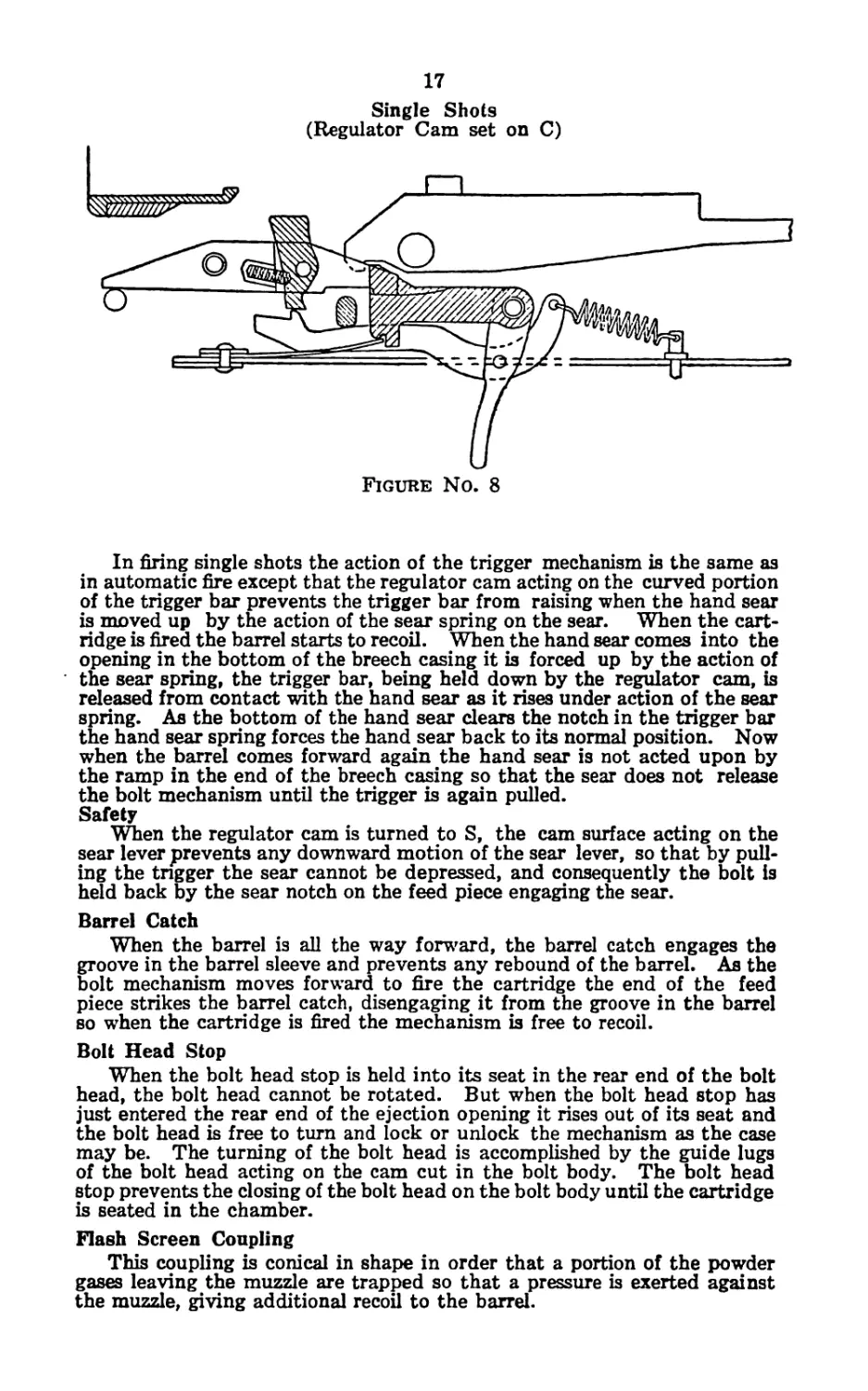
Single Shots
(Regulator Cam set on C)
Figure No. 8
In firing single shots the action of the trigger mechanism is the same as
in automatic fire except that the regulator cam acting on the curved portion
of the trigger bar prevents the trigger bar from raising when the hand sear
is moved up by the action of the sear spring on the sear. When the cart-
ridge is fired the barrel starts to recoil. When the hand sear comes into the
opening in the bottom of the breech casing it is forced up by the action of
the sear spring, the trigger bar, being held down by the regulator cam, is
released from contact with the hand sear as it rises under action of the sear
spring. As the bottom of the hand sear clears the notch in the trigger bar
the hand sear spring forces the hand sear back to its normal position. Now
when the barrel comes forward again the hand sear is not acted upon by
the ramp in the end of the breech casing so that the sear does not release
the bolt mechanism until the trigger is again pulled.
Safety
When the regulator cam is turned to S, the cam surface acting on the
sear lever prevents any downward motion of the sear lever, so that by pull-
ing the trigger the sear cannot be depressed, and consequently the bolt is
held back by the sear notch on the feed piece engaging the sear.
Barrel Catch
When the barrel is all the way forward, the barrel catch engages the
groove in the barrel sleeve and prevents any rebound of the barrel. As the
bolt mechanism moves forward to fire the cartridge the end of the feed
piece strikes the barrel catch, disengaging it from the groove in the barrel
so when the cartridge is fired the mechanism is free to recoil.
Bolt Head Stop
When the bolt head stop is held into its seat in the rear end of the bolt
head, the bolt head cannot be rotated. But when the bolt head stop has
just entered the rear end of the ejection opening it rises out of its seat and
the bolt head is free to turn and lock or unlock the mechanism as the case
may be. The turning of the bolt head is accomplished by the guide lugs
of the bolt head acting on the cam cut in the bolt body. The bolt head
stop prevents the closing of the bolt head on the bolt body until the cartridge
is seated in the chamber.
Flash Screen Coupling
This coupling is conical in shape in order that a portion of the powder
gases leaving the muzzle are trapped so that a pressure is exerted against
the muzzle, giving additional recoil to the barrel.
CARE AND PRESERVATION
The stoppages of the gun are not numerous, if proper care is observed
and the person using it has a thorough knowledge of the piece. Most of
the stoppages are caused by defective ammunition or carelessness or igno-
rance on the part of the gunner.
To quote from the French Pamphlet, “Offensive Conduct of Small
Units/’
“Arms of high efficiency are only effective when in the hands of discip-
lined and courageous experts with a thorough knowledge of the gun under
officers with an accurate understanding of the weapon.”
The regiments which used this gun at Verdun and Somme fronts who had
well trained rifle teams were enthusiastic in their praise of it. Those who
had untrained men operating the guns, due to insufficient instruction,
were the ones who complained of it. Furthermore, disciplined and couag-
eous gunners have a true love for the gun. Therefore, the care of this gun
is the point on which particular stress should be laid in instructing.
I. GUN
During the Firing:
The gunner should take advantage of a lull in the action to clean the
parts of the rifle which do not require dismounting, removing the metal
chips from the locking recess and from around the bolt. These chips are
from the cartridge case and primer. The chips are best removed by a
piece of soft wood conveniently shaped. He also should give special at-
tention to the removal of dirt from the face of the bolt taking care that the
ejector and extractor are free to function.
After Firing:
The gunner should dismount the gun and clean with a cloth. Those
parts which are very dirty should be cleaned with coal oil. The parts
which are cleaned with coal oil should be thoroughly dried before oiling,
as the coal oil if left on the gun will cause it to rust. In oiling the gun, the
oil should be placed on a soft rag, and the parts wiped with this rag, so as
not to leave an excess of oil on the parts. If too much oil is used, and the
weather is cold the oil gums and prevents proper functioning. In dry
weather the excess oil collects dust and causes excess friction, also preventing
the proper working of the gun.
Note: The gun should be oiled after the first two magazines have been
fired. Parts requiring special attention in oiling are the parts of the bolt
mechanism. The reason for oiling after the gun has been fired is that the
gun is heated up so that when the oil is applied, expecially to the cartridge
guide cam and the cam ways in the bolt body, the oil will not gum.
Cleaning:
All parts of the bolt mechanism should be thoroughly cleaned, especially
the extractor, ejector, guide lugs, cam cuts, bolt headstop, firing pin etc.
II. MAGAZINE
Great care should be used in the handling of the magazines, as they
must be in perfect condition, or they won’t feed the cartridges correctly.
After magazines have been used they should be thoroughly dried and wiped
with an oiled rag.
While filling the magazine care should be taken to see that the cartridges
19
are loaded properly into the magazine and are not forced in thereby injuri ng
the lips of the magazine, which would misplace the cartridges so that they
would not be fed properly into the chamber.
See that the magazine sides are not bent, which would prevent the free
movement of the magazine follower and spring.
See that the spring is not distorted or bent.
When the magazine spring is removed it should make a portoin of a
circle with its ends not greater than a distance of four fingers. If this dis-
tance is greater than four fingers the spring should be stretched until it has
the sufficient space between the ends. In stretching this spring, the angles
toward the center are the ones to be enlarged, and not the ones on the ex-
terior circumferance. If this does not give the spring sufficient tension it
should be replaced.
MALFUNCTIONS, STOPPAGES AND JAMS
First Phase
1. Failure to Recock:
On account of the lack of recoil, the barrel is not driven back sufficiently
to recock the piece. That is, the sear notch on the feed piece does not en-
gage the sear and hold the bolt mechanism back:
Causes:—
Insufficient gas due to defective ammunition or excess friction in the
recoiling parts.
If the gunner does not hold the gun securely against his shoulder the
barrel will not recoil because a portion of the recoil is taken up by the back-
ward movement of the whole gun.
Result:—
The bolt being locked to the barrel and not being recoiled sufficiently
to engage the sear, travels forward with the barrel so the empty cartridge
case is not extracted or ejected.
Remedy:—
Cock the gun by hand which will extract and eject the empty cartridge
case.
Second Phase
1. The Barrel does not resume its firing position.
Causes:—
Weak Recoil Spring.
Dirt around the barrel or the expansion off the barrel sleeve due to the
heat (excess friction between the barrel sleeve and breech housing).
Dirt in and around the chamber which prevents the unlocking of the
bolt head.
Result:—
The barrel cannot be separated from the bolt; the barrel has not resumed
its firing position and there is an empty cartridge case in the chamber.
Remedies:—
1. Pull the operating handle back releasing it quickly.
2. Gently strike the but with the palm of the hand.
3. Place regulating cam on “S” strike the ground with the
heel of the stock (never with the toe).
4. Dismount, clean and oil the parts.
Note: Oil the barrel sleeve through the ejection slot. Strip and clean
the rifle if necessary (cleaning during action). As a rule there is an expans-
of the sleeve after 300 or 400 rounds have been fired automatically or 700
to 1000 rounds of sinlge shots.
2. Failure to extract:
Causes:—
Defective amunition.
The bottom of the cartridge is defective.
Under or oversized cartridge.
The cartridge case sticks in the chamber
Defective extractor, spring, or pin
21
Results:—
The case cannot be removed from the chamber. If the cartridge case
sticks in the chamber, the extractor will tear off the rim of the cartridge
without extracting it.
Remedy:—
Carefully examine ammunition; if necessary change extractor spring,
remove defective cartridge case with the hand extractor.
Note: If the cartridge case cannot be removed by the hand extractor,
use the ruptured cartridge extractor.
3. Failure to eject:
Causes:—
Weak ejector spring
Ejector failing to function, due to excess friction caused by dirt.
Result:—
The empty cartridge case has not been thrown out of the ejection slot,
and remains between the side plates.
The empty cartridge case is either partly or entirely jammed in the
ejection opening. The next cartridge cannot be driven into the chamber
by the bolt.
Remedies:—
Remove the empty cartridge case by turning the gun on its right side;
also take out the new cartridge.
Clean the ejector and its seat; test the ejector spring for tension.
Third Phase
1. Failure to Feed:
Causes:—
Magazine spring weak or broken
Distorted magazine
Results:—
The cartrdges are not moved up into position to be pushed forward by
the feed piece.
Remedy:—
Change Magazine
2. Double Feeding:
Cause:
The lips of the magazine are either too wide or out of shape.
Results:
The feed piece has engaged the second cartridge due to the fact that this
cartridge is allowed to be raised above its correct position. Two cartridges
are in position to be pushed home.
Remedy:—
Change the magazine
Note: This stoppage should never occur as it is the first duty of the men
to see that the magazines are in good condition.
The magazine is one of the most delicate parts of the gun and great care
should be exercised by both the carrier and gunner to see that the magazine
is not mistreated.
22
3. Incorrect Position of the Cartridge When Ready To Be Pushed Home:
Causes:
Magazine is too wide or has been distorted.
Insufficient compression of the magazine spring, causing lack of pressure
on the follower:
The lips on the magazine being too close together do not release the
cartridge and the cartridge is made to dive instead of rise.
Lost motion in the rising of the cartridge guide caused by the cartridge
guide roller being worn.
Results:—
The bullet end of the cartridge strikes against the upper part of the
breech casing so that the bolt head on its forward travel does not strike the
base of the cartridge, but strikes against the side of the cartridge.
The cartridge strikes the cartridge guide block and the end of the feed
piece on its forward motion strikes the side of the cartridge case.
Remedies:—
Tighten the lips of the magazine or put on a good magazine.
Quickly cock the gun, compress magazine spring with your hand, and
remove damaged cartridge. If necessary, remove magazine.
4. Misfire:
Causes:—
Defective ammunition
Weak mainspring
Distorted cartridge guide cam causing excess friction between it and the
side plate or cartridge guide cam diver.
Remedies:—
Carefully examine ammunition
Pack the bottom of the spring guide tube with paper, thereby shortening
main spring, increasing its tension.
Replace main spring
Straighten cartridge guide cam
Note: Insist upon the necessity of skillful training to the gunner.
EFFECT OF WORN OR BROKEN PARTS ON ACTION OF THE
TRIGGER MECHANISM.
1. Fires automatically when set for single shots.
Causes:
The regulator cam is worn, or the curved portion of the trigger bar on
which the regulator cam acts is worn.
Lost motion in the regulator cam due to wearing on its bearings.
Results:
The regulator cam does not lower the trigger bar sufficiently to release
the hand sear when it is forced up.
The trigger bar raises the regulator cam instead of the regulator cam
lowering the trigger bar.
The notch in the end of the trigger bar acts continually on the hand sear
producing automatic fire.
Remedy:
Replace worn parts.
23
2. Regulator cam set for safety the gun fires.
Causes:
The regulator cam is loose
Results:
The regulator cam does not hold up the sear lever
The sear leer is free to move, therefore when the trigger is pulled the
sear is released from the sear notch in the feed piece, so the gun will fire.
Remedy:
Replace regulator cam.
3. When set for single shots, the gun does not fire, but works properly
when set for automatic fire.
Causes:
The curve portion of the trigger bar on which the regulator cam acts is
distorted so that the cam does not function properly. Or the notch which
engages the hand sear becomes worn.
Results;
The curved portion of the trigger bar being distorted the trigger bar is
moved down too quickly, so that its notch does not engage the hand sear.
When set for automatic fire, the regulator cam does not act on the trigger
bar, therefore the gun functions properly.
Remedy:
File the curved position of the trigger bar until it is timed in properly
so as to engage and release the hand sear at the proper time.
4. When set for single shots or automatic fire the gun does not fire.
Causes:
The axis on which the parts of the trigger mechanism move are worn
producing an excess of lost motion.
Result:
Due to this wear, the movement of the trigger is not sufficient to release
the sear as it must take up all the slack in the trigger mechanism.
Remedy:
Replace worn parts
CAUSES OF BROKEN PARTS
A. Excess gas, causing too strong a recoil
B. Premature fire
The breakages occur at the weakest place, and are most always due to
flaws in the steel.
A. Excess Gas
Produces one of the following:
1. Broken recoil spring bushing
2. Broken operating handle
3. Broken feed piece
4. Broken feed piece assembling stud
1. As the barrel recoils the recoil spring bushing strikes against the
spring guide cap with sufficient force to break it.
2. Or the oberating handle strikes the end of the opening in the side
plate which breaks the operating handle.
3. & 4. These breakages can also occur due to too strong a recoil.
Note:
Care should be observed when the operating handle breaks that the bolt
is not allowed to go forward and prime the cartridge when the butt is struck
24
to reduce the jam. In this position the feed piece is separated from the
bolt mechanism so that the bolt is free to go forward and prime the cartridge,
as the cartridge guide cam does not act on the cartridge guide, hence the
cartridge is free to go forward into the chamber. (This accident caused a
fatality in the French Army on September 20th 1916).
B. Premature Fire
Due to defective ammunition the locking lug on the bolt, in pushing
the cartridge forward will prime the cartridge, if the primer is not securely
seated in the cartridge, that is, the primer is protuding beyond the level of
the base of the cartridge. This defect causes breakages on the head of the
extractor, or will explode the breech casing.
ACTION OF THE POISON GAS ON THE MATERIAL OF THE GUN
There has been some doubt as to the action о the poison gas on the
material used in the manufacture of arms and ammunition. The following
note is of interest in order that the necessary precautions are taken and the
correct remedy applied so as to prevent the slight deterioration which re-
sults from the action of the gases on the metal.
Up to the present time the gases used by the enemy in gas attacks have
not materially affected the metal on the guns or ammunition.
Effects on the Gun
The chemical action of cholorine gas on the material has a slight oxication
effect (rust) on the exposed polished parts. The parts which are covered
with a thin coat of oil are not affected by this gas. This oxidation (rusting)
cannot be removed by the ordinary method of cleaning.
Effects on the Ammunition
The action of the chlorine gas on the cartridge cases porduces green
copper oxide which is in most cases easily removed.
The following precautions should be observed:
Glean thoroughly as soon as possible those parts which have been exposed
to the action of the gas.
Lubricating oil is the best protection for the material in the gun and
ammunition.
Cartridges which have been exposed to the action of the gas should not
be used in the gun; but should be turned in and cleaned and then re-issued.
QUESTIONS COVERING THE CHAUCHAT AUTOMATIC MACHINE
RIFLE, MODEL 1915.
1. Give the correct method of dismounting.
2. What type is this gun and make?,
3. How cooled?
4. Why is aluminum used for radiator?
5. What forces operate the gun?
6. How is the magazine loaded?
7. How is bolt mechanism locked?
8. How is the ejection affected?
9. What aids the recoil of the barrel?
10. What is the correct method for placing the magazine in the gun?
11. Describe in detail the precautions necessary for the care of the
Magaiznes.
12. If the cartridge is in an incorrect position in the lips of the magazine,
how can it be corrected?
13. What precautions are necessary in removing the magazine from
the gun?
14. What is accomplished by the recoil of the barrel?
15. What is accomplished by the return of the barrel to its forward
position?
16. What is accomplished by the forward motion of the bolt mech-
anism?
17. What is the function of the feed piece?
18. What is the function of the cartridge guide cam?
19. What is the function of the barrel catch?
20. What is the purpose of the bolt stem collar?
21. What is the function of the bolt head stop?
22. What is the function of the cartridge guide roller?
23. What is the function of the magazine stop spring?
24. What is the function of the spring guide latch?
25. Trace the transmission of power when the trigger is pulled through
the trigger mechanism.
26. What is the purpose of the recoil spring bushing?
27. What is the purpose of the barrel nut?
28. Give the action of the trigger mechanism when the regulator cam
is set for single shots; when set for automatic fire.
29. On what does the regulator cam act when set on safety?
30. To what are the side plates assembled?
31. Can the bipod be put on incorrectly?
32. What is the purpose of the magazine catch handle?
33. What is assembled on the barrel catch block?
34. Give the correct method of assembling the housing to the rifle
carriage.
35. Can the rear assembling bolt be removed from the gun? And if
not, why?
36. In what position is the bolt mechanism when it is assembled to the
breech casing?
37. In what position is the breech casing and bolt mechanism when the
feed piece is assembled to the bolt body?
38. Describe in detail correct method of oiling the gun.
39. What is the result of excess oil?
40. In dismounting for cleaning during action, what are the duties of
the gunner; of the first carrier? of the second carrier?
41. After the gun has been fired a considerable time, to what parts
should special attention be paid in cleaning?
42. When the magazine is in the gun, what holds the front end in place?
26
43. Can the cartridge guide cam cover bolts be removed from the
right side of the gun?
44. If the cartridge guide cam binds on the cartridge guide cam cover,
causing excess friction, can it be remedied, and if so, how?
45. In firing while marching, why should the butt stock be held se-
curely under the arm with the spring guide cap firmily held against the
muscle of the shoulder?
46. What is the correct position of the gunner’s body while firing in
marching?
47. What is the purpose of the flash screen?
48. What causes the hand sear to be depressed when firing automatic?
49. What is the purpose of the barrel sleeve?
50. What is the purpose of the spring washer on the rear assembling
bolt?
51. What precaution would you take for your own safety?
52. What are the duties of the members of the rifle team in regard to
the functioning of the gun before firing, during the firing and after the firing?
53. What would prevent the barrel and breech casing from recoiling?
Give remedies.
54. What would prevent them from resuming their firing position?
Give remedies.
55. What is the cause of failure to extract? Give remedies.
56. What are the causes of failure to eject? Give remedies.
57. What are the causes of failure to feed? Give remedies.
58. What causes the incorrect position of the cartridge when it is ready
to be pushed home?
59. What are the causes of mis-fire?
60. What are the causes of a hang-fire?
61. What causes the trigger mechanism to fire automatically when set
for single shots?
62. What causes the gun to fire when the regulator cam is set on safety?
63. When set for single shots, the gun does not fire, but works properly
when set on automatic. What is the cause?
64. Wbat is the trouble if, when set for single shots or automatic, the
gun does not fire?
65. What are the causes of broken parts?
66. What would cause a premature fire?
67. What is the weight of the gun?
68. If the mainspring was weak, how would you strengthen it?
69. If the gun is subjected to the action of poison gas, what immediate
action would you take?
70. What is the weight of a full magazine?
71. What is the capacity of the magazine?
72. Give a two weeks’ schedule of instruction on the mechanism of
this gun.
73. Can the bolt head be assembled incorrectly?
74. If the barrel fails to resume its firing position, how would you
make it go forward without dismounting the gun?
75. What parts are likely to break due to too strong a recoil?