/


Tags: weapons military affairs
Year: 1918


Text
Provisional Instruction
ON THE
Automatic Rifle, Model 1915
(Chauchat)
No. 8
Translated from the French Edition
of February, 1916
Revised to June 9, 1917, at Headquarters
American Expeditionary Forces
France
From Col. Jno. P. Ftnlby,-U. S. Arm
Officer in Charge Militia Affairj
Governors Island, N. Y.
Reprinted, by the
ARMY WAR COLLEGE,
- * , / /
January, 1918
War Department.
Document No. 732.
Office of The Adjutant General.
WAR DEPARTMENT,
Washington, January df 1918.
The following pamphlet, “Provisional Instructions on the
Automatic Rifle, Model 1915 (Chauchat),” is published for the
information of all concerned.
[A. G. O., No. 062.1.]
By order of the Secretary of War.
TASKER H. BLISS,
\
General, Chief of Staff.
Official :
H. P. McCAIN,
The Adjutant General»
2
PART I.
AUTOMATIC RIFLE, 1915 MODEL.
CHAPTER I.
CHARACTERISTICS, DESCRIPTION
AND NOMENCLATURE OF THE RIFLE.
I.—Characteristics.
The automatic rifle, 1915 model, is an automatic rifle utilizing
the recoil strength. It is classed among the guns of this cate-
gory acting by long recoil of the barrel.
It fires the French regulation cartridge 86 D. (with modified-
priming). The feeding is done by clips containing twenty
cartridges. This gun can be fired round by round (intermittent
firing) or automatically (machine-gun firing).
П.—Description and Nomenclature.
The gun is divided in two principal parts:
(a) A nonrecoiling part,
(b) A movable part,
(a) NONRECOILING PART.
The nonrecoiling part includes:
1° The barrel cover guide.
2° The receiver.
3° The firing mechanism.
4° The fittings.
1. The Barrel Cover Guide.—Is made out of steel sheet; is
used to protect the barrel and to guide its movements. It is
formed of two tubes, fixed together by the front screw collar,
and carries at its forepart the flash cover, screwed and set; the
front sight carrier, which, by its truncated shape, decreases the
internal diameter of the barrel cover guide, constituting some
sort of recoil intensifier.
The barrel cover guide is-bored at its forepart with eighteen
holes, allowing the circulation of the air around the radiator.
On the right, the ejection opening; below, the carrier opening,
in which slides the carrier fixed to the movable breech. The
slide is hollowed out at its posterior part to allow the mounting
3
and dismounting of the carrier; at its anterior part to allow
the working of the cartridge guiding shuttle.
The back part of the barrel cover guide is ended by the rear
screw collar, on which is screwed the plug sustaining the recoil
springs.
The plug includes the plug itself, the threading, and the recoil
springs guide.
The front and rear screw collar, carry, respectively, an as-
sembling clasp and an eyehole stud, allowing the securing of
the barrel cover guide on the receiver by means of the assem-
bling bolts.
The front screw collar has internally a recoil shoulder, on
which strikes the forepart of the barrel’s sleeve when the sleeve
is at its firing position.
On the middle part of the barrel cover guide is fixed the rear
sight.
2. The Receiver.—The receiver is formed of two side plates,
joined by transoms and fixed at the back on the butt.
On the right side plate are to be seen:
The axis holes of the swivel, of the front assembling bolt, of
the conhecting rod guide; the holes for the passing of the fixing
screws of the middle transom; the axis holes of the trigger, of
the safety lock, of the sear lever, of the rear swivel, and of the
rear assembling bolt.
The right side plate possesses a hollowed out part for the
sliding motion of the operating handle.
On the left side plate are to be seen:
The same axis holes as on the right plate and the holes of the
fixing screws of the shuttle transom and of the connecting rod
guide.
Holding together the two side plates there are:
The bipod transom, whose anterior part is either threaded or
tapped for the screwing of the bipod’s axle-bearing head. It
holds also the front assembling bolt.
The shuttle transom, which carries:
(a) The barrel lever stop, whose nose, lodging itself in a circular
notch of the barrel’s sleeve, plays the part of keeping the latter
at its firing position. This lever includes the nose, the body,
and the toe, a spring, resting on one side on the transom (un-
movable point), and on the other side on the toe (movable
point), forcing the nose upwards.
(b) The clip support spring, to fo'rce off the clip when catch is
released.
(c) The cartridge guiding shuttle, pivoting around two trunnionr
lodged in the side plates, secures the correct introduction
4 •
the cartridge in the barrel. This shuttle includes a ramp, on
which slides the point of the bullet, pushed in direction of the
barrel by the carrier. The shuttle, which, while the gun is
working, is to have an elevating and a lowering motion, is
operated by the connecting rod through a roller axle.
The shuttle transom is fixed to the side plates by two screws,
securing also the connecting rod guide on the right side plate.
The middle transom, at the interior part of which are to be
seen:-
(a) The carrying handle, fixed to the transom by a screwed rod.
(b) The clip catch, moved by its handle, forced forward by its
spring (unmovable point; transom, movable point; hook). The
middle transom is fixed to the side plates by two screws.
The butt, on which one can see a steel plate sunk in the
wood, and the recess of the plug-stop.
3. Firing Mechanism.—The firing mechanism of the 1915
model automotic gun is fitted on a receiver formed by two side
plates and a bottom plate. On the side plates there are the
axis holes of the trigger, of the safety lock, and of the sear lever.
On the bottom plate there are the bar spring eyebolt and the
hollowed out part for the passing of the trigger tail and of the
bar bow.
The receiver is ended at its lower part by the pistol grip
covered with wooden plates fixed by two screws.
Fixing together the bottom plate and the grip is the trigger
guard. Between the two side plates we have:
(a) The bar spring (unmovable point; the eyebolt, movable
point; the bar).
This spring forces the bar and the trigger’s tail forward.
(5) The bar, on which are the eyehole, the rounded part, the
body, the inclined plane, the toe.
(c) The trigger, with its axle bearing and its tail. The trigger
is fixed with the bar by the bar pin. *
(d) The sear, with its axle bearing, its head and the supports
of the sear spring. The sear is fixed to the trigger by a tubed
pin.
(?) The sear spring (unmovable point bottom plate-movable
point, support surface of the sear) forces the head of the sear
upward.
(/) The sear lever, on which are to be seen the forepart (axle
bearing shaped), the bed of the sear lever tubed pin, the tail.
On the forepart of the lever is fixed the stud by the means of the
strut-axle.
{g) The strut, which includes the head and its rounded part,
the lower arm.
5
(Л) The strut spring (unmovable point, sear lever movable
point, strut lower arm) forces the strut lower arm forward.
(i) The safety lock passes across the side plates perpendicu-
larly and includes the lever with its lug and its center punch; the
axle, with the lifter.
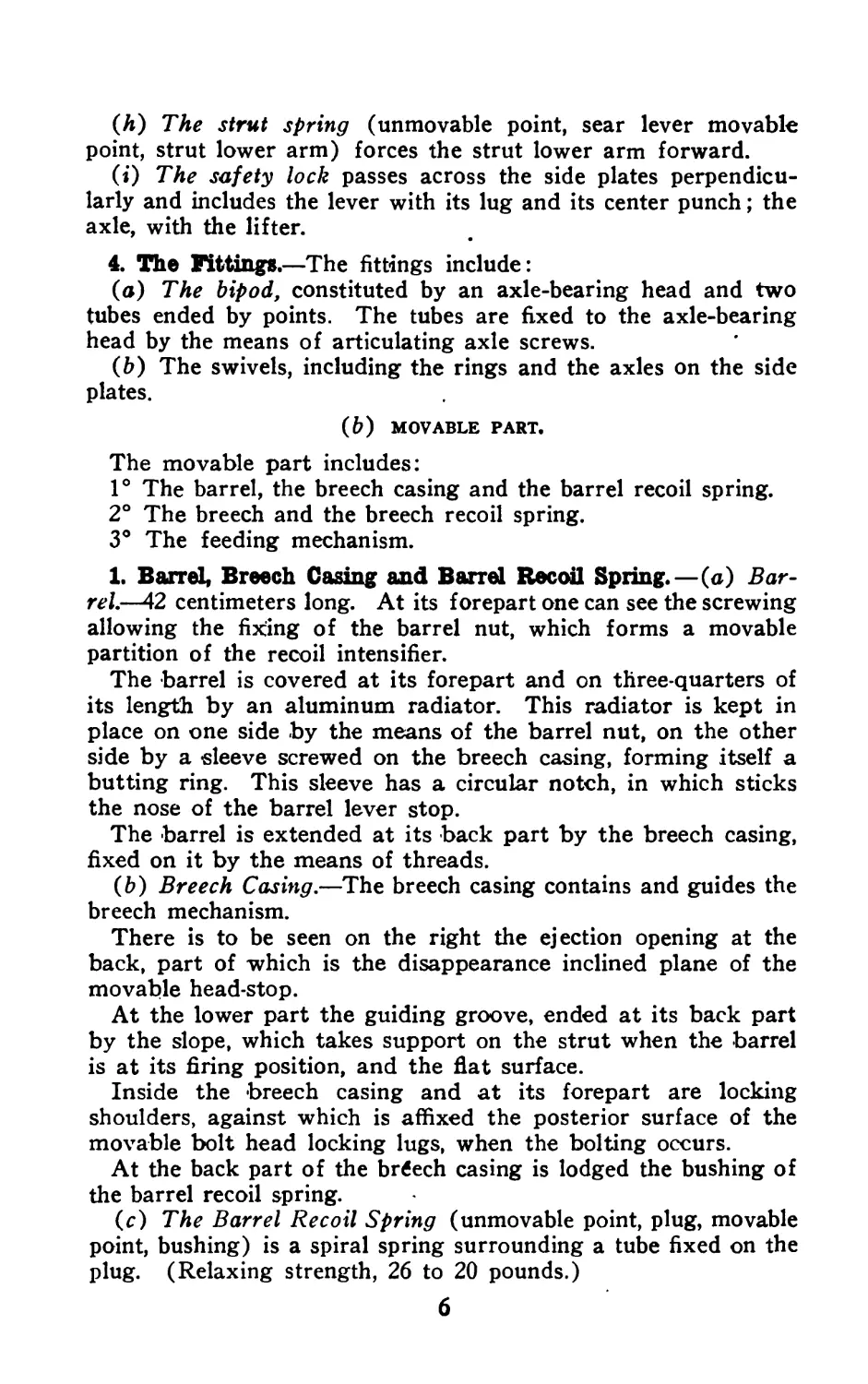
4. The Fittings.—The fittings include:
(a) The bipod, constituted by an axle-bearing head and two
tubes ended by points. The tubes are fixed to the axle-bearing
head by the means of articulating axle screws.
(b) The swivels, including the rings and the axles on the side
plates.
(&) MOVABLE PART.
The movable part includes:
1° The barrel, the breech casing and the barrel recoil spring.
2° The breech and the breech recoil spring.
3° The feeding mechanism.
1. Barrel, Breech Casing and Barrel Recoil Spring.—(a) Bar-
rel.—42 centimeters long. At its forepart one can see the screwing
allowing the fixing of the barrel nut, which forms a movable
partition of the recoil intensifier.
The barrel is covered at its forepart and on three-quarters of
its length by an aluminum radiator. This radiator is kept in
place on one side by the means of the barrel nut, on the other
side by a sleeve screwed on the breech casing, forming itself a
butting ring. This sleeve has a circular notch, in which sticks
the nose of the barrel lever stop.
The barrel is extended at its back part by the breech casing,
fixed on it by the means of threads.
(&) Breech Casing.—The breech casing contains and guides the
breech mechanism.
There is to be seen on the right the ejection opening at the
back, part of which is the disappearance inclined plane of the
movable head-stop.
At the lower part the guiding groove, ended at its back part
by the slope, which takes support on the strut when the barrel
is at its firing position, and the flat surface.
Inside the breech casing and at its forepart are locking
shoulders, against which is affixed the posterior surface of the
movable bolt head locking lugs, when the bolting occurs.
At the back part of the brtfech casing is lodged the bushing of
the barrel recoil spring.
(c) The Barrel Recoil Spring (unmovable point, plug, movable
point, bushing) is a spiral spring surrounding a tube fixed on the
plug. (Relaxing strength, 26 to 20 pounds.)
6
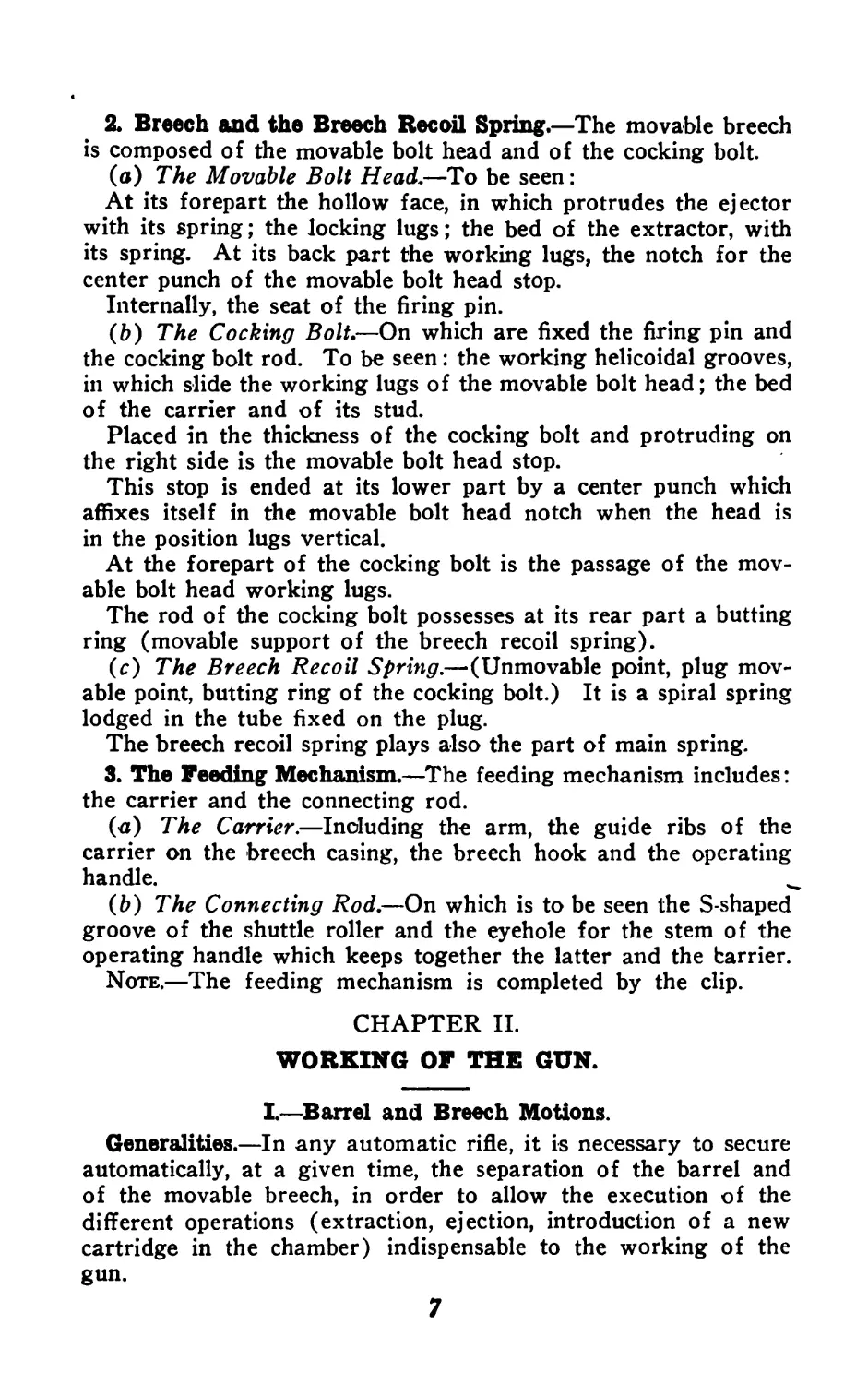
2. Breech and the Breech Recoil Spring.—The movable breech
is composed of the movable bolt head and of the cocking bolt.
(a) The Movable Bolt Head.—To be seen:
At its forepart the hollow face, in which protrudes the ejector
with its spring; the locking lugs; the bed of the extractor, with
its spring. At its back part the working lugs, the notch for the
center punch of the movable bolt head stop.
Internally, the seat of the firing pin.
(&) The Cocking Bolt.—On which are fixed the firing pin and
the cocking bolt rod. To be seen: the working helicoidal grooves,
in which slide the working lugs of the movable bolt head; the bed
of the carrier and of its stud.
Placed in the thickness of the cocking bolt and protruding on
the right side is the movable bolt head stop.
This stop is ended at its lower part by a center punch which
affixes itself in the movable bolt head notch when the head is
in the position lugs vertical.
At the forepart of the cocking bolt is the passage of the mov-
able bolt head working lugs.
The rod of the cocking bolt possesses at its rear part a butting
ring (movable support of the breech recoil spring).
(c) The Breech Recoil Spring.—(Unmovable point, plug mov-
able point, butting ring of the cocking bolt.) It is a spiral spring
lodged in the tube fixed on the plug.
The breech recoil spring plays also the part of main spring.
3. The Feeding Mechanism.—The feeding mechanism includes:
the carrier and the connecting rod.
(<x) The Carrier.—Including the arm, the guide ribs of the
carrier on the breech casing, the breech hook and the operating
handle.
(b) The Connecting Rod.—On which is to be seen the S-shaped
groove of the shuttle roller and the eyehole for the stem of the
operating handle which keeps together the latter and the barrier.
Note.—The feeding mechanism is completed by the clip.
CHAPTER II.
WORKING OF THE GUN.
I.—Barrel and Breech Motions.
Generalities.—In any automatic rifle, it is necessary to secure
automatically, at a given time, the separation of the barrel and
of the movable breech, in order to allow the execution of the
different operations (extraction, ejection, introduction of a new
cartridge in the chamber) indispensable to the working of the
gun.
7
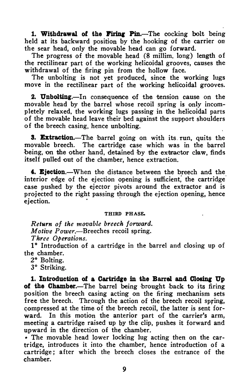
In the automatic rifle, 1915 model, the movable whole (barrel,
breech) is sent backward by the recoil strength, after which the
barrel is brought back to its firing position by its recoil spring,
while the breech held backwards cannot come back to its first
position until the barrel is at its complete forward position.
The separation of the barrel and of the breech is then completed.
Working.—To fire, one must: cock the breech mechanism,
then hook the clip under the gun, placing the fore extremity be-
tween the bipod transom and the barrel cover, and the back
extremity on the clip catch.
When acting on the trigger, the breech mechanism loads the
gun and produces the discharge. In the barrel and breech
motion of the automatic rifle 1915 model, three phases must be
considered:
ist phase. Recoil of the barrel and the breech (the two pieces
joined).
2nd phase. Return of the barrel to its firing position.
3rd phase. Return of the movable breech forward.
FIRST PHASE.
Recoil of the barrel and breech. (The two pieces joined.)
Motive power. The gas.
One operation. Cocking.
The first shot occurs, the gas acting on the movable breech
sends it backwards. As the breech is bolted to the barrel, this
is sent backward, too. The recoil springs are compressed. The
movable breech (and accordingly the firing pin) being at, its
extreme backward position, the breech recoil spring (acting in
this case as main spring) being compressed, the cocking is
effected.
Maintenance of the cocking.—The maintenance of the cocking
is secured by the hooking of the breech hook on the sear head.
SECOND PHASE.
Return of the barrel to its firing position.
Motive Power.—Barrel recoil spring.
Four operations.
1° Withdrawal of the firing pin.
2° Unbolting.
3° Extraction.
4° Ejection.
As soon as the action of the gas disappears, the barrel recoil
spring is relaxed and sends the barrel forward.
The barrel going forward forces the movable bolt head, to
which it is bolted, to accompany it in its action.
8
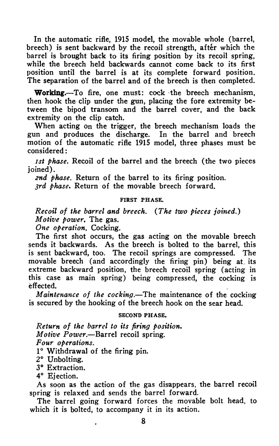
1. Withdrawal of the Firing Pin.—The cocking bolt being
held at its backward position by the hooking of the carrier on
the sear head, only the movable head can go forward.
The progress of the movable head (8 millim. long) length of
the rectilinear part of the working helicoidal grooves, causes the
withdrawal of the firing pin from the hollow face.
The unbolting is not yet produced, since the working lugs
move in the rectilinear part of the working helicoidal grooves.
2. Unbolting.—In consequence of the tension cause on the
movable head by the barrel whose recoil spring is only incom-
pletely relaxed, the working lugs passing in the helicoidal parts
of the movable head leave their bed against the support shoulders
of the breech casing, hence unbolting.
3. Extraction.—The barrel going on with its run, quits the
movable breech. The cartridge case which was in the barrel
being, on the other hand, detained by the extractor claw, finds
itself pulled out of the chamber, hence extraction.
4. Ejection.—When the distance between the breech and the
interior edge of the ejection opening is sufficient, the cartridge
case pushed by the ejector pivots around the extractor and is
projected to the right passing through the ejection opening, hence
ejection.
THIRD PHASE.
Return of the movable breech forward.
Motive Power.—Breeches recoil spring.
Three Operations.
1° Introduction of a cartridge in the barrel and closing up of
the chamber.
2° Bolting.
3° Striking.
1. Introduction of a Cartridge in the Barrel and Closing Up
of the Chamber.—The barrel being brought back to its firing
position the breech casing acting on the firing mechanism sets
free the breech. Through the action of the breech recoil spring,
compressed at the time of the breech recoil, the latter is sent for-
ward. In this motion the anterior part of the carrier’s arm,
meeting a cartridge raised up by the clip, pushes it forward and
upward in the direction of the chamber.
• The movable head lower locking lug acting then on the car-
tridge, introduces it into the chamber, hence introduction of a
cartridge; after which the breech closes the entrance of the
chamber.
9
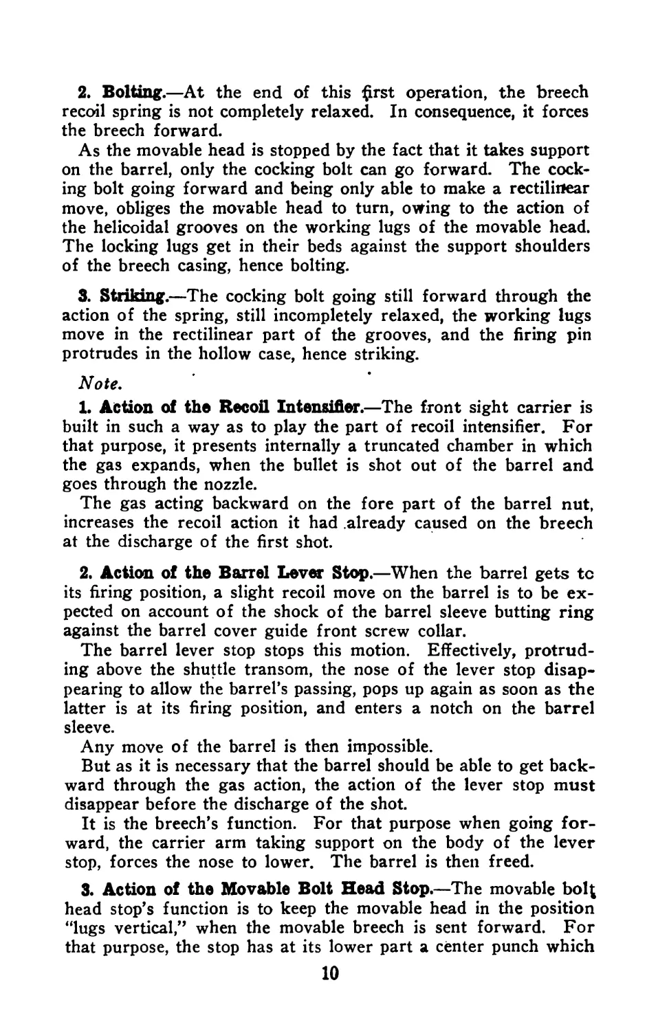
2. Bolting.—At the end of this £rst operation, the breech
recoil spring is not completely relaxed. In consequence, it forces
the breech forward.
As the movable head is stopped by the fact that it takes support
on the barrel, only the cocking bolt can go forward. The cock-
ing bolt going forward and being only able to make a rectilinear
move, obliges the movable head to turn, owing to the action of
the helicoidal grooves on the working lugs of the movable head.
The locking lugs get in their beds against the support shoulders
of the breech casing, hence bolting.
3. Striking.—The cocking bolt going still forward through the
action of the spring, still incompletely relaxed, the working lugs
move in the rectilinear part of the grooves, and the firing pin
protrudes in the hollow case, hence striking.
Note,
1. Action of the Recoil Intensifier.—The front sight carrier is
built in such a way as to play the part of recoil intensifier. For
that purpose, it presents internally a truncated chamber in which
the gas expands, when the bullet is shot out of the barrel and
goes through the nozzle.
The gas acting backward on the fore part of the barrel nut,
increases the recoil action it had already caused on the breech
at the discharge of the first shot.
2. Action of the Barrel Lever Stop.—When the barrel gets tc
its firing position, a slight recoil move on the barrel is to be ex-
pected on account of the shock of the barrel sleeve butting ring
against the barrel cover guide front screw collar.
The barrel lever stop stops this motion. Effectively, protrud-
ing above the shuttle transom, the nose of the lever stop disap-
pearing to allow the barrel’s passing, pops up again as soon as the
latter is at its firing position, and enters a notch on the barrel
sleeve.
Any move of the barrel is then impossible.
But as it is necessary that the barrel should be able to get back-
ward through the gas action, the action of the lever stop must
disappear before the discharge of the shot.
It is the breech’s function. For that purpose when going for-
ward, the carrier arm taking support on the body of the lever
stop, forces the nose to lower. The barrel is then freed.
3. Action of the Movable Bolt Head Stop.—The movable ЬоЦ
head stop’s function is to keep the movable head in the position
“lugs vertical,” when the movable breech is sent forward. For
that purpose, the stop has at its lower part a center punch which
10
gets into a notch prepared -at the rear part of the movable head,
while the latter is in the position “lugs vertical.” Any rotation
of the movable head is then impossible as the stop taking sup-
port by its higher part on the internal partition of the breech
casing, cannot raise itself and allow the coming out from its bed
in the movable head notch of the center punch.
But when the movable head is practically in touch with the bar-
rel it is necessary that the action of the stop should disappear, so
as to allow the freeing of the movable head which has to turn for
the bolting. The stop center punch must at that instant leave its
bed in the notch of the movable head.
For that purpose, when the movable head is forced to turn,
the action of the notch’s inclined edges on the stop center punch,
permits the raising of the latter which gets out of its bed in the
movable head. This raising up is possible, for when the bolting
occurs the high part of the stop protruding in the ejection open-
ing is no longer in touch with the internal partition of the breech
casing.
П—Firing Mechanism.
The automatic rifle, 1915 model, firing mechanism permits two
kinds of firing:
1° Automatic firing.
2° Round by round firing or intermittent firing.
The execution of these two kinds of firing is ruled by the posi-
tion given to the safety lock lifter.
1. AUTOMATIC FIRING.
• Position of the Lifter.—Horizontal (the lifter takes support on
the strut bar). (Safety lock at M).
A striking has occurred:
The barrel and the breech are sent backward. The breech is
detained. The gunner, keeping the action of his finger on the
trigger, the strut bar pushed backwards compresses its spring
and takes support on the strut lower arm.
It operates in that way, the pivoting of the strut around its
axle in such a way that the rounded part of the strut head finds
itself in the path of the breech casing. At the same time the strut
lever arm compresses the strut spring and takes support on
the sear lever.
The barrel coming back to its forward position, the slope of
the breech casing guiding groove meeting the strut’s head, the
latter is pressed forward.
This motion being possible no longer, the strut being in touch
with the sear lever there is lowering of the strut axle and con-
sequently lowering of the fore part of the sear lever. Besides
. 11
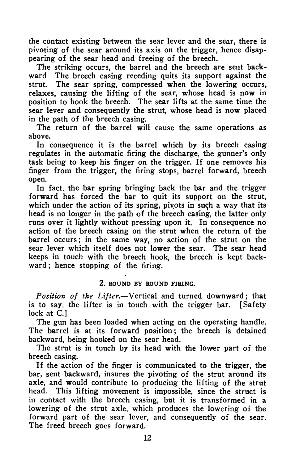
the contact existing between the sear lever and the sear, there is
pivoting of the sear around its axis on the trigger, hence disap-
pearing of the sear head and freeing of the breech.
The striking occurs, the barrel and the breech are sent back-
ward The breech casing receding quits its support against the
strut. The sear spring, compressed when the lowering occurs,
relaxes, causing the lifting of the sear, whose head is now in
position to hook the breech. The sear lifts at the same time the
sear lever and consequently the strut, whose head is now placed
in the path of the breech casing.
The return of the barrel will cause the same operations as
above.
In consequence it is the barrel which by its breech casing
regulates in the automatic firing the discharge, the gunner’s only
task being to keep his finger on the trigger. If one removes his
finger from the trigger, the firing stops, barrel forward, breech
open.
In fact, the bar spring bringing back the bar and the trigger
forward has forced the bar to quit its support on the strut,
which under the action of its spring, pivots in suc^h a way that its
head is no longer in the path of the breech casing, the latter only
runs over it lightly without pressing upon it. In consequence no
action of the breech casing on the strut when the return of the
barrel occurs; in the same way, no action of the strut on the
sear lever which itself does not lower the sear. The sear head
keeps in touch with the breech hook, the breech is kept back-
ward; hence stopping of the firing.
2. ROUND BY ROUND FIRING.
Position of the Lifter,—Vertical and turned downward; that
is to say, the lifter is in touch with the trigger bar. [Safety
lock at C.]
The gun has been loaded when acting on the operating handle.
The barrel is at its forward position; the breech is detained
backward, being hooked on the sear head.
The strut is in touch by its head with the lower part of the
breech casing.
If the action of the finger is communicated to the trigger, the
bar, sent backward, insures the pivoting of the strut around its
axle, and would contribute to producing the lifting of the strut
head. This lifting movement is impossible, since the struct is
in contact with the breech casing, but it is transformed in a
lowering of the strut axle, which produces the lowering of the
forward part of the sear lever, and consequently of the sear.
The freed breech goes forward.
12
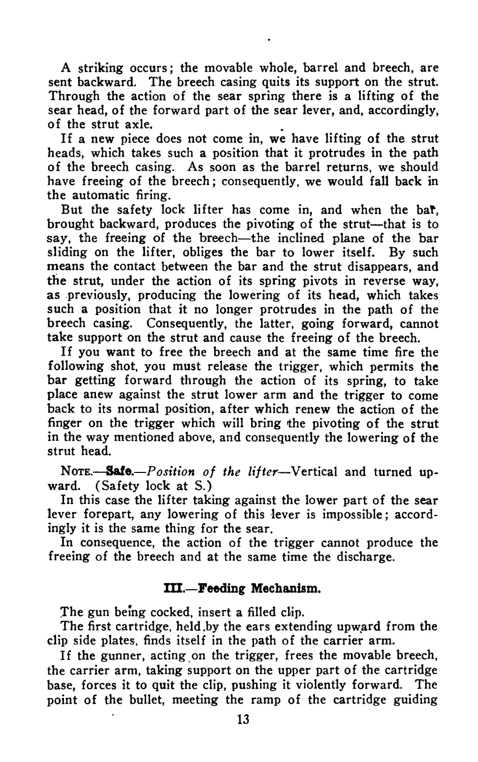
A striking occurs; the movable whole, barrel and breech, are
sent backward. The breech casing quits its support on the strut.
Through the action of the sear spring there is a lifting of the
sear head, of the forward part of the sear lever, and, accordingly,
of the strut axle.
If a new piece does not come in, we have lifting of the strut
heads, which takes such a position that it protrudes in the path
of the breech casing. As soon as the barrel returns, we should
have freeing of the breech; consequently, we would fall back in
the automatic firing.
But the safety lock lifter has come in, and when the bat,
brought backward, produces the pivoting of the strut—that is to
say, the freeing of the breech—the inclined plane of the bar
sliding on the lifter, obliges the bar to lower itself. By such
means the contact between the bar and the strut disappears, and
the strut, under the action of its spring pivots in reverse way,
as previously, producing the lowering of its head, which takes
such a position that it no longer protrudes in the path of the
breech casing. Consequently, the latter, going forward, cannot
take support on the strut and cause the freeing of the breech.
If you want to free the breech and at the same time fire the
following shot, you must release the trigger, which permits the
bar getting forward through the action of its spring, to take
place anew against the strut lower arm and the trigger to come
back to its normal position, after which renew the action of the
finger on the trigger which will bring the pivoting of the strut
in the way mentioned above, and consequently the lowering of the
strut head.
Note.—Safe.—Position of the lifter—Vertical and turned up-
ward. (Safety lock at S.)
In this case the lifter taking against the lower part of the sear
lever forepart, any lowering of this lever is impossible; accord-
ingly it is the same thing for the sear.
In consequence, the action of the trigger cannot produce the
freeing of the breech and at the same time the discharge.
1П.—Feeding Mechanism.
The gun being cocked, insert a filled clip.
The first cartridge, held .by the ears extending upward from the
clip side plates, finds itself in the path of the carrier arm.
If the gunner, acting on the trigger, frees the movable breech,
the carrier arm, taking support on the upper part of the cartridge
base, forces it to quit the clip, pushing it violently forward. The
point of the bullet, meeting the ramp of the cartridge guiding
13
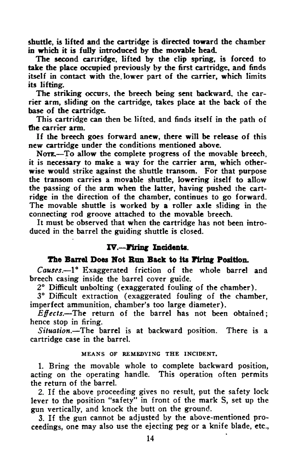
shuttle, is lifted and the cartridge is directed toward the chamber
in which it is fully introduced by the movable head.
The second cartridge, lifted by the clip spring, is forced to
take the place occupied previously by the first cartridge, and finds
itself in contact with the. lower part of the carrier, which limits
its lifting.
The striking occurs, the breech being sent backward, the car-
rier arm, sliding on the cartridge, takes place at the back of the
base of the cartridge.
This cartridge can then be lifted, and finds itself in the path of
the carrier arm.
If the breech goes forward anew, there will be release of this
new cartridge under the conditions mentioned above.
Note.—To allow the complete progress of the movable breech,
it is necessary to make a way for the carrier arm, which other-
wise would strike against the shuttle transom. For that purpose
the transom carries a movable shuttle, lowering itself to allow
the passing of the arm when the latter, having pushed the cart-
ridge in the direction of the chamber, continues to go forward.
The movable shuttle is worked by a roller axle sliding in the
connecting rod groove attached to the movable breech.
It must be observed that when the cartridge has not been intro-
duced in the barrel the guiding shuttle is closed.
IV.—Firing Incidents.
The Barrel Does Not Run Back to its Firing Position.
Causes.—1° Exaggerated friction of the whole barrel and
breech casing inside the barrel cover guide.
2° Difficult unbolting (exaggerated fouling of the chamber).
3° Difficult extraction (exaggerated fouling of the chamber,
imperfect ammunition, chamber’s too large diameter).
Effects.—The return of the barrel has not been obtained;
hence stop in firing.
Situation.—The barrel is at backward position. There is a
cartridge case in the barrel.
MEANS OF REMEDYING THE INCIDENT.
1. Bring the movable whole to complete backward position,
acting on the operating handle. This operation often permits
the return of the barrel.
2. If the above proceeding gives no result, put the safety lock
lever to the position “safety” in front of the mark S, set up the
gun vertically, and knock the butt on the ground.
3. If the gun cannot be adjusted by the above-mentioned pro-
ceedings, one may also use the ejecting peg or a knife blade, etc.,
14
taking support on the back of the cover guide ejection opening
and pressing on the barrel in order to bring it forward. This
proceeding must be used only exceptionally.
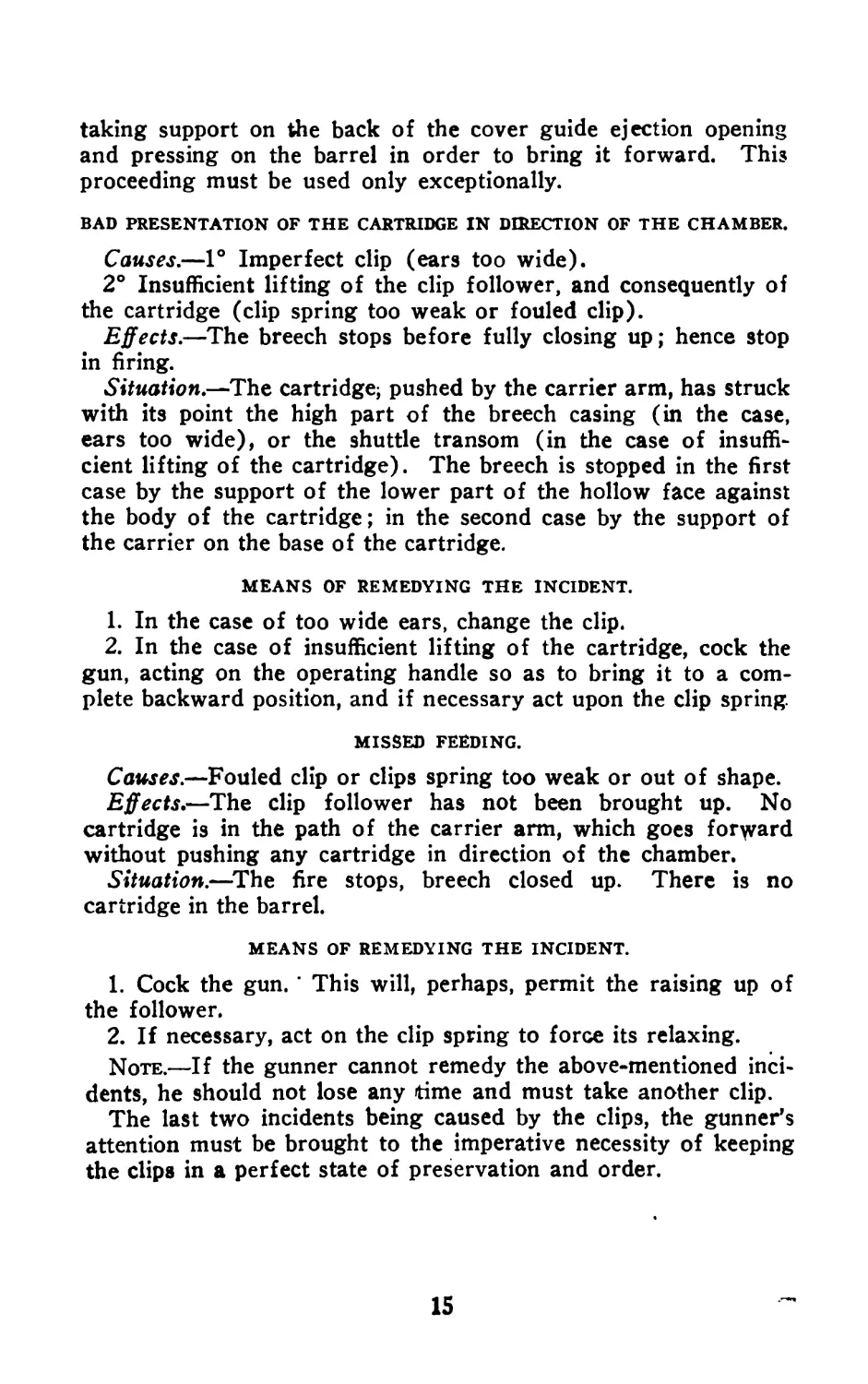
BAD PRESENTATION OF THE CARTRIDGE IN DIRECTION OF THE CHAMBER.
Causes.—1° Imperfect clip (ears too wide).
2° Insufficient lifting of the clip follower, and consequently of
the cartridge (clip spring too weak or fouled clip).
Effects.—The breech stops before fully closing up; hence stop
in firing.
Situation.—The cartridge; pushed by the carrier arm, has struck
with its point the high part of the breech casing (in the case,
ears too wide), or the shuttle transom (in the case of insuffi-
cient lifting of the cartridge). The breech is stopped in the first
case by the support of the lower part of the hollow face against
the body of the cartridge; in the second case by the support of
the carrier on the base of the cartridge.
MEANS OF REMEDYING THE INCIDENT.
1. In the case of too wide ears, change the clip.
2. In the case of insufficient lifting of the cartridge, cock the
gun, acting on the operating handle so as to bring it to a com-
plete backward position, and if necessary act upon the clip spring.
MISSED FEEDING.
Causes.—Fouled clip or clips spring too weak or out of shape.
Effects,—The clip follower has not been brought up. No
cartridge is in the path of the carrier arm, which goes forward
without pushing any cartridge in direction of the chamber.
Situation.—The fire stops, breech closed up. There is no
cartridge in the barrel.
MEANS OF REMEDYING THE INCIDENT.
1. Cock the gun. ’ This will, perhaps, permit the raising up of
the follower.
2. If necessary, act on the clip spring to force its relaxing.
Note.—If the gunner cannot remedy the above-mentioned inci-
dents, he should not lose any time and must take another clip.
The last two incidents being caused by the clips, the gunner’s
attention must be brought to the imperative necessity of keeping
the clips in a perfect state of preservation and order.
15
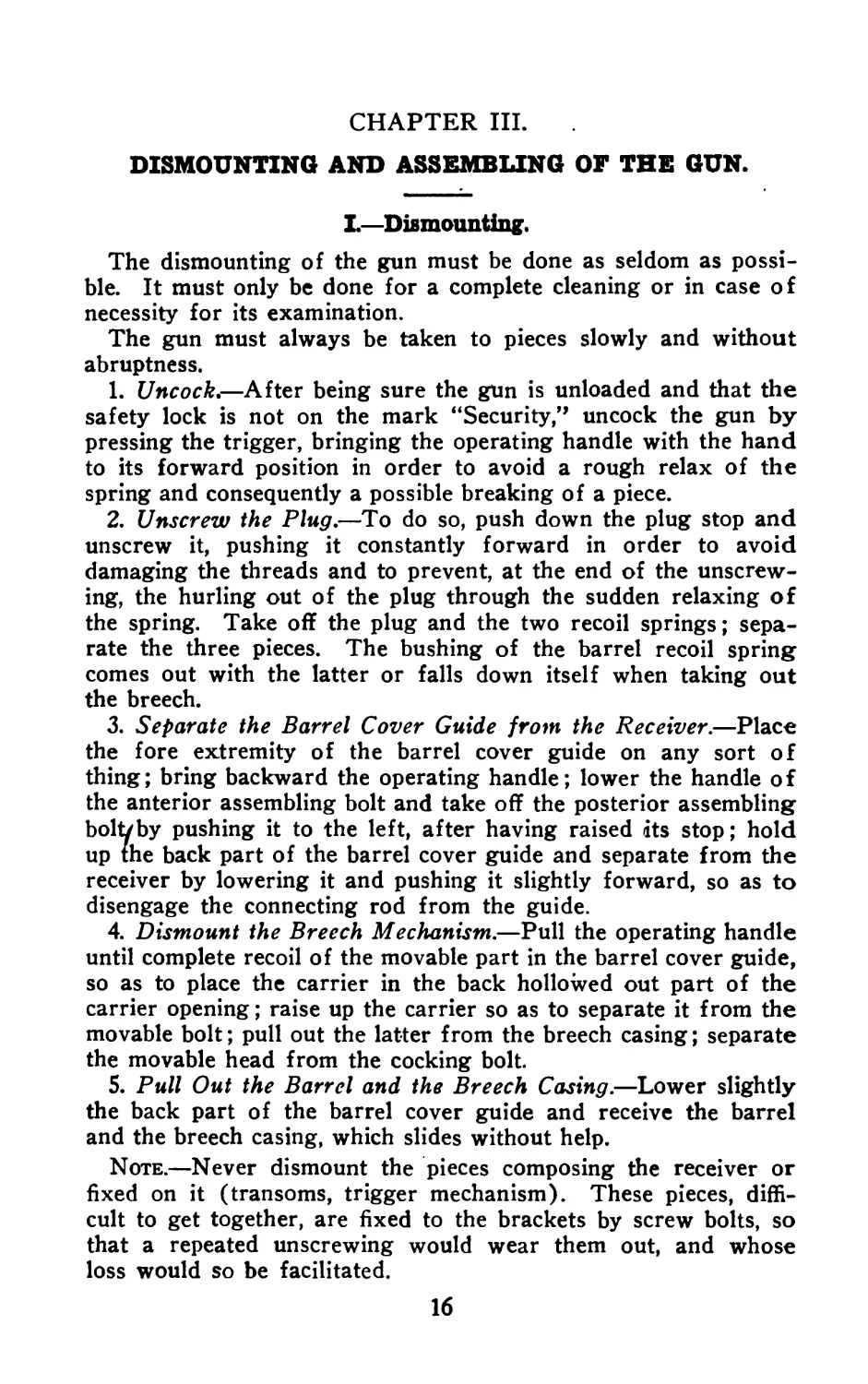
CHAPTER III.
DISMOUNTING AND ASSEMBLING OF THE GUN.
I.—Dismounting.
The dismounting of the gun must be done as seldom as possi-
ble. It must only be done for a complete cleaning or in case of
necessity for its examination.
The gun must always be taken to pieces slowly and without
abruptness.
1. Uncock,—After being sure the gun is unloaded and that the
safety lock is not on the mark “Security,” uncock the gun by
pressing the trigger, bringing the operating handle with the hand
to its forward position in order to avoid a rough relax of the
spring and consequently a possible breaking of a piece.
2. Unscrew the Plug,—To do so, push down the plug stop and
unscrew it, pushing it constantly forward in order to avoid
damaging the threads and to prevent, at the end of the unscrew-
ing, the hurling out of the plug through the sudden relaxing of
the spring. Take off the plug and the two recoil springs; sepa-
rate the three pieces. The bushing of the barrel recoil spring
comes out with the latter or falls down itself when taking out
the breech.
3. Separate the Barrel Cover Guide from the Receiver.—Place
the fore extremity of the barrel cover guide on any sort of
thing; bring backward the operating handle; lower the handle of
the anterior assembling bolt and take off the posterior assembling
boltvby pushing it to the left, after having raised its stop; hold
up the back part of the barrel cover guide and separate from the
receiver by lowering it and pushing it slightly forward, so as to
disengage the connecting rod from the guide.
4. Dismount the Breech Mechanism.—Pull the operating handle
until complete recoil of the movable part in the barrel cover guide,
so as to place the carrier in the back hollowed out part of the
carrier opening; raise up the carrier so as to separate it from the
movable bolt; pull out the latter from the breech casing; separate
the movable head from the cocking bolt.
5. Pull Out the Barrel and the Breech Casing.—Lower slightly
the back part of the barrel cover guide and receive the barrel
and the breech casing, which slides without help.
Note.—Never dismount the pieces composing the receiver or
fixed on it (transoms, trigger mechanism). These pieces, diffi-
cult to get together, are fixed to the brackets by screw bolts, so
that a repeated unscrewing would wear them out, and whose
loss would so be facilitated.
16
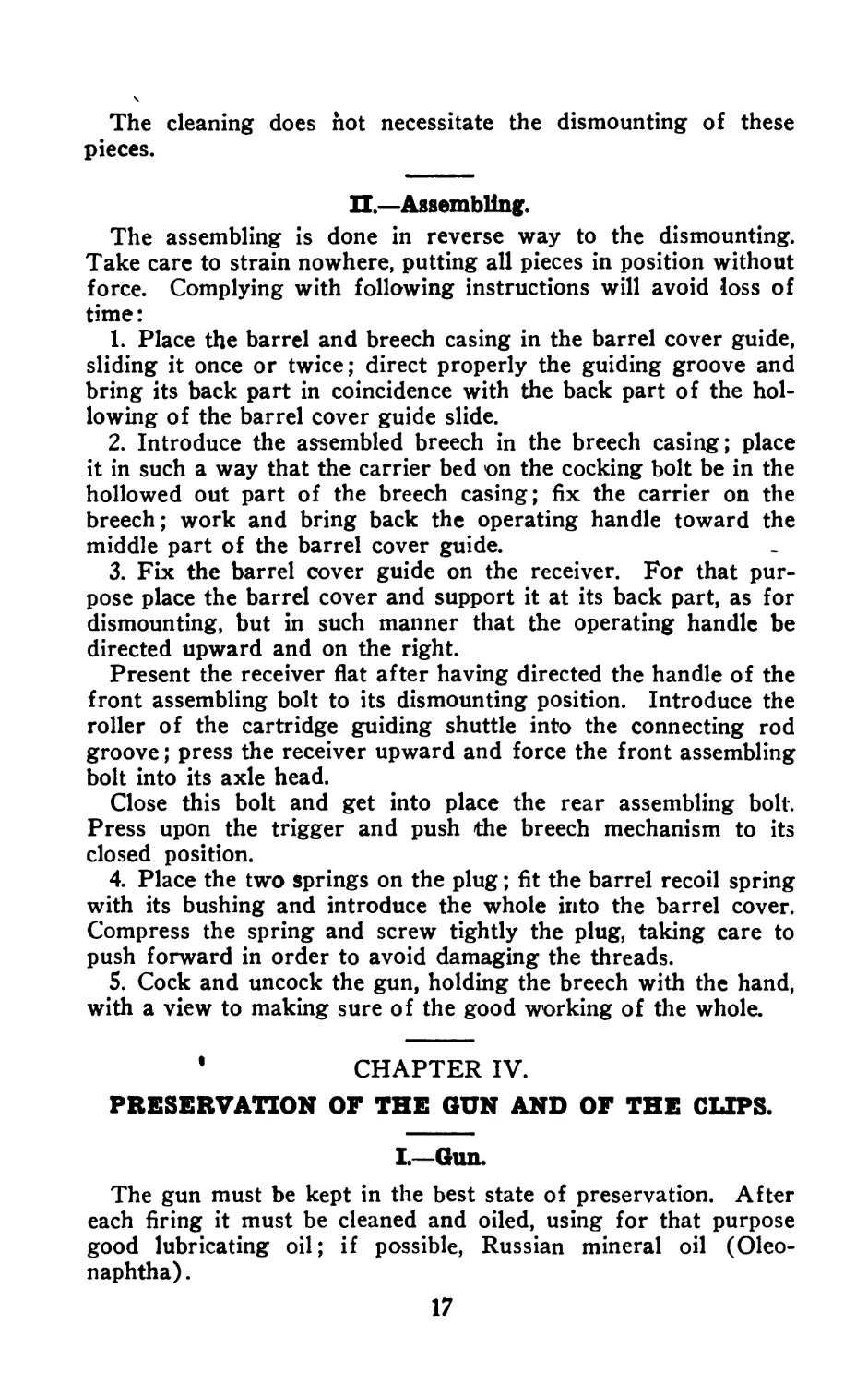
The cleaning does hot necessitate the dismounting of these
pieces.
П,—Assembling.
The assembling is done in reverse way to the dismounting.
Take care to strain nowhere, putting all pieces in position without
force. Complying with following instructions will avoid loss of
time:
1. Place the barrel and breech casing in the barrel cover guide,
sliding it once or twice; direct properly the guiding groove and
bring its back part in coincidence with the back part of the hol-
lowing of the barrel cover guide slide.
2. Introduce the assembled breech in the breech casing; place
it in such a way that the carrier bed on the cocking bolt be in the
hollowed out part of the breech casing; fix the carrier on the
breech; work and bring back the operating handle toward the
middle part of the barrel cover guide.
3. Fix the barrel cover guide on the receiver. For that pur-
pose place the barrel cover and support it at its back part, as for
dismounting, but in such manner that the operating handle be
directed upward and on the right.
Present the receiver flat after having directed the handle of the
front assembling bolt to its dismounting position. Introduce the
roller of the cartridge guiding shuttle into the connecting rod
groove; press the receiver upward and force the front assembling
bolt into its axle head.
Close this bolt and get into place the rear assembling bolt.
Press upon the trigger and push the breech mechanism to its
closed position.
4. Place the two springs on the plug; fit the barrel recoil spring
with its bushing and introduce the whole into the barrel cover.
Compress the spring and screw tightly the plug, taking care to
push forward in order to avoid damaging the threads.
5. Cock and uncock the gun, holding the breech with the hand,
with a view to making sure of the good working of the whole.
1 CHAPTER IV.
PRESERVATION OF THE GUN AND OF THE CLIPS.
I.—Gun.
The gun must be kept in the best state of preservation. After
each firing it must be cleaned and oiled, using for that purpose
good lubricating oil; if possible, Russian mineral oil (Oleo-
naphtha).
17
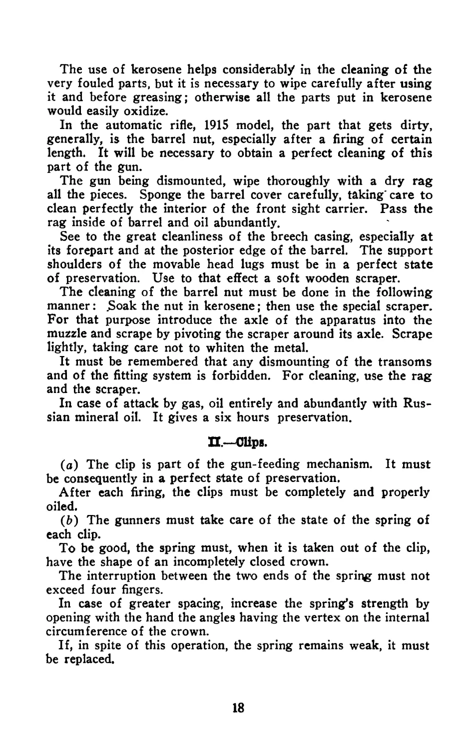
The use of kerosene helps considerably in the cleaning of the
very fouled parts, but it is necessary to wipe carefully after using
it and before greasing; otherwise all the parts put in kerosene
would easily oxidize.
In the automatic rifle, 1915 model, the part that gets dirty,
generally, is the barrel nut, especially after a firing of certain
length. It will be necessary to obtain a perfect cleaning of this
part of the gun.
The gun being dismounted, wipe thoroughly with a dry rag
all the pieces. Sponge the barrel cover carefully, taking'care to
clean perfectly the interior of the front sight carrier. Pass the
rag inside of barrel and oil abundantly.
See to the great cleanliness of the breech casing, especially at
its forepart and at the posterior edge of the barrel. The support
shoulders of the movable head lugs must be in a perfect state
of preservation. Use to that effect a soft wooden scraper.
The cleaning of the barrel nut must be done in the following
manner: £oak the nut in kerosene; then use the special scraper.
For that purpose introduce the axle of the apparatus into the
muzzle and scrape by pivoting the scraper around its axle. Scrape
lightly, taking care not to whiten the metal.
It must be remembered that any dismounting of the transoms
and of the fitting system is forbidden. For cleaning, use the rag
and the scraper.
In case of attack by gas, oil entirely and abundantly with Rus-
sian mineral oil. It gives a six hours preservation.
П-Clips.
(a) The clip is part of the gun-feeding mechanism. It must
be consequently in a perfect state of preservation.
After each firing, the clips must be completely and properly
oiled.
(b) The gunners must take care of the state of the spring of
each clip.
To be good, the spring must, when it is taken out of the clip,
have the shape of an incompletely closed crown.
The interruption between the two ends of the spring must not
exceed four fingers.
In case of greater spacing, increase the spring’s strength by
opening with the hand the angles having the vertex on the internal
circumference of the crown.
If, in spite of this operation, the spring remains weak, it must
be replaced.
18
PART II.
AMMUNITION.
I.—Cartridges.
The automatic rifle, 1915 model, uses the cartridge 1886 D
model (with modified priming), placed twenty in the clips.
П —Clips*
The clip is made out of sheet steel. Its shape is that of a seg-
ment. It is composed of two side plates and two bottom plates,
forming a transom. One of the side plates is full; the other is
bored through, allowing a view of the internal part of the clip.
Ribs secure the stiffness of the clips and the guiding of the
cartridges.
One of the ends is closed with a stop plate (used as a support
for the spring). The nose of the plate, protruding externally
from the clip, is used to fasten the clip on the receiver. The
other end is open to permit the passing of the cartridges.
Two ears, extending the side plates, make it impossible for
the cartridges to come out from the clip unless they are forced
to do so by pressure on the cartridge base.
Inside of the clip there is a follower, whose part is to push the
cartridges continuously toward the hole.
This follower is moved by a double bow spring, having its
movable support on the clip stop plate.
Ш.—Loading of the Clip.
To load the clip, lower the follower with the hand a distance
equal to the thickness of the cartridge.
Engage a cartridge, the base first; let it lie down on the fol-
lower ; lower this one anew and go on with the loading, lowering
progressively the follower, so as to permit the passing of the
cartridge to be engaged. The clip is filled up when it contains
twenty cartridges. (Usually eighteen gives the best result.)
To empty a clip, push gradually on the base of the cartridges,
in the same manner, the carrier arm would do in working.
Note.—It will be found advantageous not to keep the clips
filled up without necessity, so as not to strain the spring.
19
IV.—Seating of the Clip on the Gun.
To seat the clip on the gun, cock the gun, seize the clip with
the right hand, and curve downward, the follower backward.
Place the stop plate, the nose directed upward, between the
bipod transom and the shuttle transom. Then force the clip
home until it engages the clip catch.
To disengage the clip, bring the operating handle to extreme
backward position, to secure the hooking of the breech. Press
forward the handle of the clip catch, and take off the clip with
the hand. The clip would, without this precaution, fall down by
itself under the action of the clip support spring.
PART III.
OUTFIT.
The outfit of the automatic rifle, 1915 model, is placed in a
small cleaning kit, which may be carried either inside the sack or
above it by the means of the sack straps.
The outfit carried ih this kit is:
One three-pieced ramrod.
One barrel sponge.
One cleaning rod.
One barrel cover guide and breech casing sponge.
One socket extractor, 1907 model.
One ejection peg.
One oil can.
One kerosene can.
One barrel nut scraper.
One screw driver.
21
PART IV.
GUNNER’S EQUIPMENT AND ARMAMENT.
I.—Gunner.
(a) Equipment.—The gunner’s equipment permits the carry-
ing of 160 cartridges (clips of 20).
It is composed of two pouches, containing each two clips and
a bag for the carrying of four clips and a cleaning kit pouch.
The pouches are carried on the front of the belt, the curve
inside. They are held by the hooks of the suspenders.
At the back the gunner carries a flat cartridge pouch, contain-
ing an automatic pistol.
The gunner carries, besides a shovel, a bag containing reserve
supplies, a canteen and a tent cloth. With a view to firing while
marching, he is provided with an extra hook for suspending
strap and with a metallic triangle for the rifle sling.1
(b) Placing of the Clips.—1. In the bag.—Place the four clips,
the ears toward the bottom of the bag, the convexity turned up-
ward, then the cleaning kit in the remaining space above.
2. In the pouches.—Place the two clips in each pouch, the curve
toward the bottom of the pouch.
(c) Armament.—Beside the automatic gun placed in a cover
and carried by the sling, the gunner carries an automatic pistol
(caliber 7mm. 65) and three clips of nine cartridges, two in the
pouch and one in the pistol.
П.—First Carrier.
(a) Equipment.—The carrier’s equipment is organized in such
a way as to permit the carrying of 480 cartridges.
It is composed of a bag and haversack arranged to avoid the
clips getting out of shape.
This haversack can be put on and taken off rapidly. It has
’The suspending strap hook is fixed to the left shoulder strap by means
of a hole punched about 5 centimeters from the highest part of the shoulder.
The hook point, bent outward, must be slightly curved forward in order to
facilitate the hooking on of the triangle. The metallic triangle consists of
a 7-mm. wire, bent in the shape of an equilateral triangle, each side being
55-mm. (inside measure). The triangle is then brazed or soldered. The
interior angles are rounded off with a rat-tail file.
23
straps allowing the external stowing of a camping article,4 if
necessary.
The cartridge bag is slung across the left shoulder and fixed
besides by three loops to the sword belt
The carrier has no suspenders. He carries a shovel, a bag, a
canteen and a tent cloth.
(b) Placing oC the Clips.—In the haversack and at the bottom
a packet of sixty-four cartridges, on the top 8 clips, superim-
posed in a parallel way, the convexity turned externally. A strap
fixes the whole inside the sack and prevents the jolting.
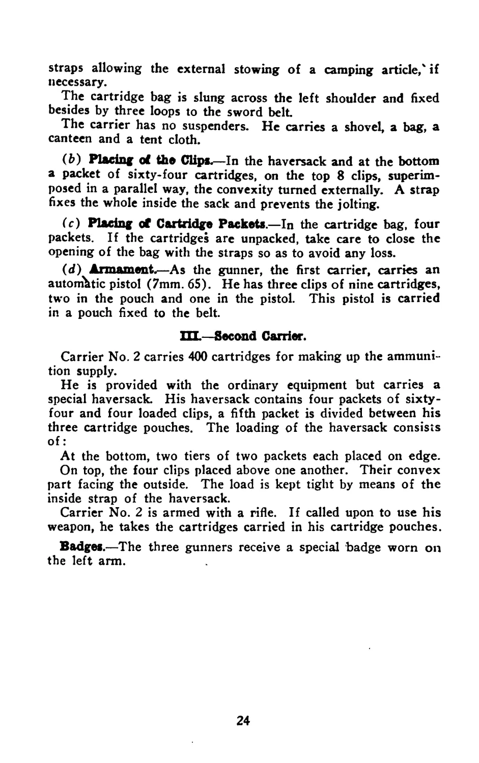
(c) Placing of Cartridge Packets.—In the cartridge bag, four
packets. If the cartridges are unpacked, take care to close the
opening of the bag with the straps so as to avoid any loss.
(d) Armament.—As the gunner, the first carrier, carries an
automatic pistol (7mm. 65). He has three clips of nine cartridges,
two in the pouch and one in the pistol. This pistol is carried
in a pouch fixed to the belt.
Ш.—Second Carrier.
Carrier No. 2 carries 400 cartridges for making up the ammuni-
tion supply.
He is provided with the ordinary equipment but carries a
special haversack. His haversack contains four packets of sixty-
four and four loaded clips, a fifth packet is divided between his
three cartridge pouches. The loading of the haversack consists
of:
At the bottom, two tiers of two packets each placed on edge.
On top, the four clips placed above one another. Their convex
part facing the outside. The load is kept tight by means of the
inside strap of the haversack.
Carrier No. 2 is armed with a rifle. If called upon to use his
weapon, he takes the cartridges carried in his cartridge pouches.
Badges.—The three gunners receive a special badge worn on
the left arm.
24
PART V.
SERVICE OF THE AUTOMATIC GUN.
I—Staff.
The gun is served by three gunners, one gunner, properly
speaking, and two carriers.
These gunners must be chosen among vigorous, intelligent
men, having excellent sight and sharpshooters.
Never take left-handed men.
The gunner and the two carriers receive the same education.
In case of necessity, one carrier only can secure the service of
the gun. «
П.—Firing.
During the march the gunner and the first carrier carry alter-
nately the gun in the sling; the gun is covered with a sheath
whose object is to preserve it from the rain or the dust.
As soon as an engagement is threatened, the gunner takes the
gun in the hand during' the whole advance in skirmish order.
As a rule he only takes out the gun from the sheath when firing.
(The empty sheath is placed on the gunner’s belt.)
During the advance the carriers conform to the gunner’s move-
ments. The three men lie down upon arriving upon the assigned
or chosen position, the two carriers on the right of the gunner.
(This position is not absolute, the carriers occupying, according
to the circumstances, the most favorable place.) The carriers
take off their haversacks.
After having chosen the place to lay his gun, the gunner pulls
the gun from its sheath, unfolds the bipod and disposes the gun
in the enemy’s direction, as a rule on the bipod or eventually on
any sort of support. He takes position to make the aiming as
easy as possible. Regularly, the position lying down must be the
same taken for the ordinary rifle, the body slightly oblique to the
gun, and resting on the elbows brought together, as much as pos-
sible, the gun held by the right hand on the pistol grip, the left
hand under the butt.
To use or to better a shelter, keep in mind the necessity of
avoiding the touching of the barrel cover guide to the ground
as anything getting between the barrel cover and the radiator in-
terferes with the firing.
25
During the different above-mentioned operations, the first car-
rier opens his haversack, takes a clip and hands it to the gunner,
after which he places his open haversack by the gunner’s hand.
The gunner having set his rear sight, cocks the gun and engages
a clip under the gun in the way mentioned in part two (Part II).
He sets his safety lock at the rear position if he wants to fire
round by round, or at the vertical position if he wants to fire
automatically, in front of the marks C (round by round) or M
(automatic).
To execute the round by round firing, the gunner presses on the
trigger and lets it go after each shot fired; he renews the finger’s
action on the trigger when he wants to fire a new shot. In this
sort of firing, the gunner lays his gun anew after each shot; he
only fires when he is sure of his aim.
For the execution of the automatic firing, the gunner keeping
the finger’s action on the trigger, must strive to keep his line of
sight on the chosen target
He stops the firing if necessary to lay his gun anew.
The good execution of the firing depends upon the gunner’s
coolness and ability.
The firing must be sharp. The gunner aims at the target foot.
In case of target changing, stop the firing, lay the gun on the new
target and start firing only when the gun is properly laid.
When the clip is empty, the gunner brings fully backward the
operating handle, so as to secure the hooking on the sear of the
breech hook. Then, pressing the handle of the clip catch, he re-
ceives the clip in the right hand, which falls down through the
action of the clip spring.
The empty clip is placed on the haversack flap, so as to keep
it out of the dirt, and a new clip is placed in the gun.
During the firing, the carriers reload the empty clips given them
by the gunner.
They useifor that purpose; the first carrier, the cartridges
carried in his cartridge bag; the second carrier uses the packet
carried in the haversack, then those contained in the second car-
rier’s pouches and calls the attention of the chief to the fact that
ammunition is required.
All favorable circumstances must be used during the fight to
make up again the ammunition stock of the gunners.
For the execution of a rush or a change of position, the gunner
prepares to carry his gun; he folds the bipod and when it is neces-
sary leaves the clip on the gun, the carriers replace rapidly their
clips or their cartridge packets in their haversacks, tying the
interior strap, closing their sacks and putting them on the back.
The gunners are then ready to rush on.
. 26
The use of the clips carried in the pockets is generally as fol-
lows : if the beginning of the fire must be immediate, the gunner
will use his clips before using those carried in the haversacks.
In the contrary case, the clips carried in the pouches should be
considered as a reserve for the gunner.
In the first case the gunner must do his best to replace this
reserve by filling up his pouch with new clip*.
A perfect* understanding must exist between the three men
called to use the gun. The gunner’s initiative must tend to obtain
the best efficiency in governing the rapidity of fire, according to
orders given, or the importance of the result which should be ob-
tained, remembering that the firing is always efficient at short
distance, and in a way to avoid the wasting of ammunition and
the exaggerated overheating of the gun.
To be sure of the good working of the clips, the gunner must
give very special attention to avoid getting them out of shape and
allow nothing to get inside.
It may be good, when the gunner is called to lie down or to
crawl, to push backward the clip pouches.
The pouches can be held in that position by tying them behind
with a strap, a string, or any other thing. If during the ad-
vance the first carrier disappears, the gunner has four clips in his
bag, with which he can fire without touching his reserve clips.
If the gunner be disabled, the first carrier must take the gun,
and take his place, since he possesses six' clips in his haversack.
The second carrier will see constantly that no clip is left on
the field.
The firing can also be executed while marching.
The firing while marching is done either by order, or on the
gunner’s initiative.
It is generally executed, round by round, and in critical mo-
ments by short rafales, exceptionally by long rafales. It is of
great use during the advance of a wave, it allows the latter to
reach the assigned objective without immediate danger, the enemy
finding himself under the necessity of keeping intrenched to avoid
the intensive firing of the gunner.
A well trained valorous gunner, can, by marching on the parapet
parallel to the trench or the communication trench, help con-
siderably in the cleaning up, by holding under his fire any enemy
who might have some resisting power.
Firing while marching is performed as follows:
The weapon is kept horizontal by means of a metallic triangle
fixed to the suspending strap hook and by the right elbow press-
ing on the butt, the length of the rifle sling is regulated accord-
27
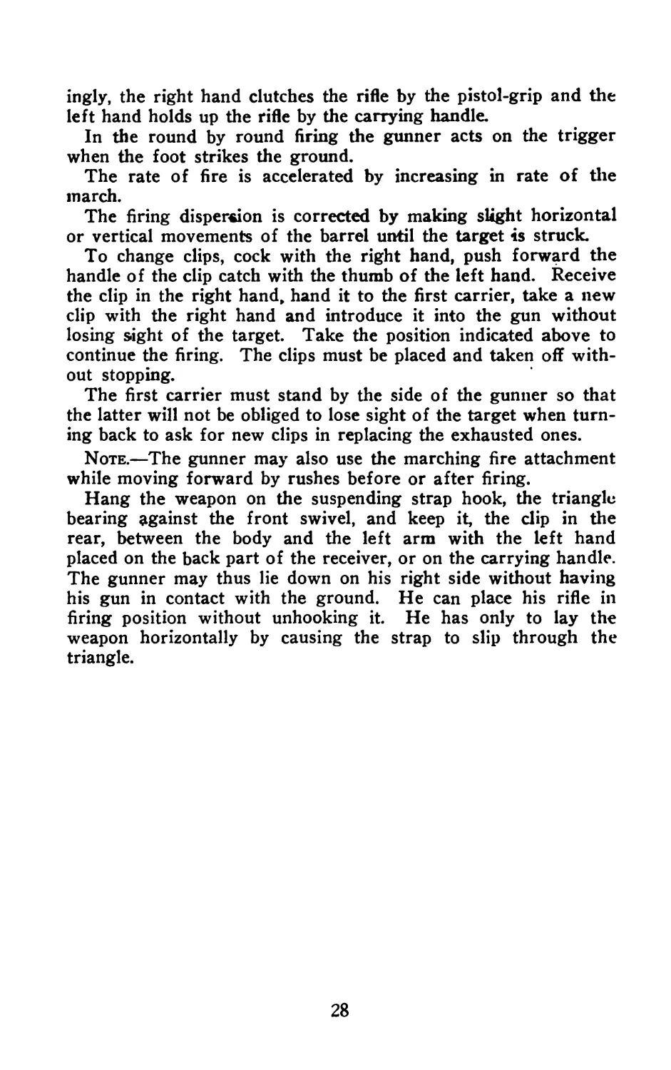
ingly, the right hand clutches the rifle by the pistol-grip and the
left hand holds up the rifle by the carrying handle.
In the round by round firing the gunner acts on the trigger
when the foot strikes the ground.
The rate of fire is accelerated by increasing in rate of the
inarch.
The firing dispersion is corrected by making slight horizontal
or vertical movements of the barrel until the target is struck.
To change clips, cock with the right hand, push forward the
handle of the clip catch with the thumb of the left hand. Receive
the clip in the right hand, hand it to the first carrier, take a new
clip with the right hand and introduce it into the gun without
losing sight of the target. Take the position indicated above to
continue the firing. The clips must be placed and taken off with-
out stopping.
The first carrier must stand by the side of the gunner so that
the latter will not be obliged to lose sight of the target when turn-
ing back to ask for new clips in replacing the exhausted ones.
Note.—The gunner may also use the marching fire attachment
while moving forward by rushes before or after firing.
Hang the weapon on the suspending strap hook, the triangle
bearing against the front swivel, and keep it, the clip in the
rear, between the body and the left arm with the left hand
placed on the back part of the receiver, or on the carrying handle.
The gunner may thus lie down on his right side without having
his gun in contact with the ground. He can place his rifle in
firing position without unhooking it. He has only to lay the
weapon horizontally by causing the strap to slip through the
triangle.
28
PART VI.
SUNDRY REFERENCES
1 .—Numerical References.
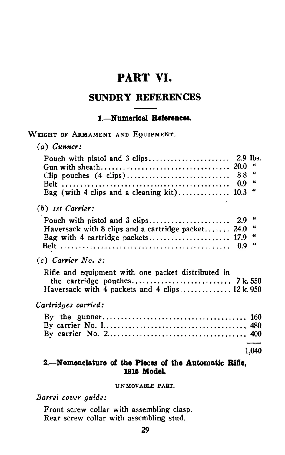
Weight of Armament and Equipment.
(a) Gunner:
Pouch with pistol and 3 clips................... 2.9 lbs.
Gun with sheath................................ 20.0 “
Clip pouches (4 clips).......................... 8.8 “
Belt ........................................... 0.9 “
Bag (with 4 clips and a cleaning kit).......... 10.3 “
(b) 1st Carrier:
Pouch with pistol and 3 clips................... 2.9 “
Haversack with 8 clip’s and a cartridge packet.24.0 “
Bag with 4 cartridge packets................... 17.9 “
Belt............................................ 0.9 “
(c) Carrier No. 2:
Rifle and equipment with one packet distributed in
the cartridge pouches.......................... 7 k. 550
Haversack with 4 packets and 4 clips...........12 k. 950
Cartridges carried:
By the gunner........................................ 160
By carrier No. 1..................................... 480
By carrier No. 2..................................... 400
1,040
2 .—Nomenclature of the Pieces of the Automatic Rifle,
1915 Model
UN MOVABLE part.
Barrel cover guide:
Front screw collar with assembling clasp.
Rear screw collar with assembling stud.
29
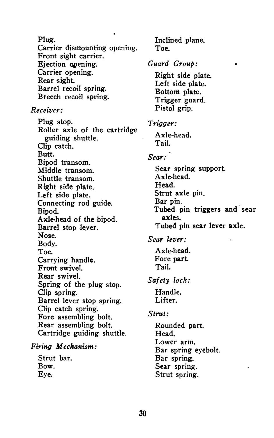
Plug. Carrier dismounting opening. Front sight carrier. Ejection opening. Carrier opening. Rear sight. Barrel recoil spring. Breech recoil spring. Inclined plane. Toe. Guard Group: Right side plate. Left side plate. Bottom plate. Trigger guard.
Receiver: Plug stop. Roller axle of the cartridge guiding shuttle. Clip catch. Butt. Bipod transom. Middle transom. Shuttle transom. Right side plate. Left side plate. Connecting rod guide. Bipod. Axle-head of the bipod. Barrel stop lever. Nose. Body. Toe. Carrying handle. Front swivel. Rear swivel. Spring of the plug stop. Clip spring. Barrel lever stop spring. Clip catch spring. Fore assembling bolt. Rear assembling bolt. Cartridge guiding shuttle. Firing Mechanism: Strut bar. Bow. Eye. Pistol grip. Trigger: Axle-head. Tail. Sear: Sear spring support. Axle-head. Head. Strut axle pin. Bar pin. Tubed pin triggers and sear axles. Tubed pin sear lever axle. Sear lever: Axle-head. Fore part Tail. Safety lock: Handle. Lifter. Strut: Rounded part. Head. Lower arm. Bar spring eyebolt. Bar spring. Sear spring. Strut spring.
30
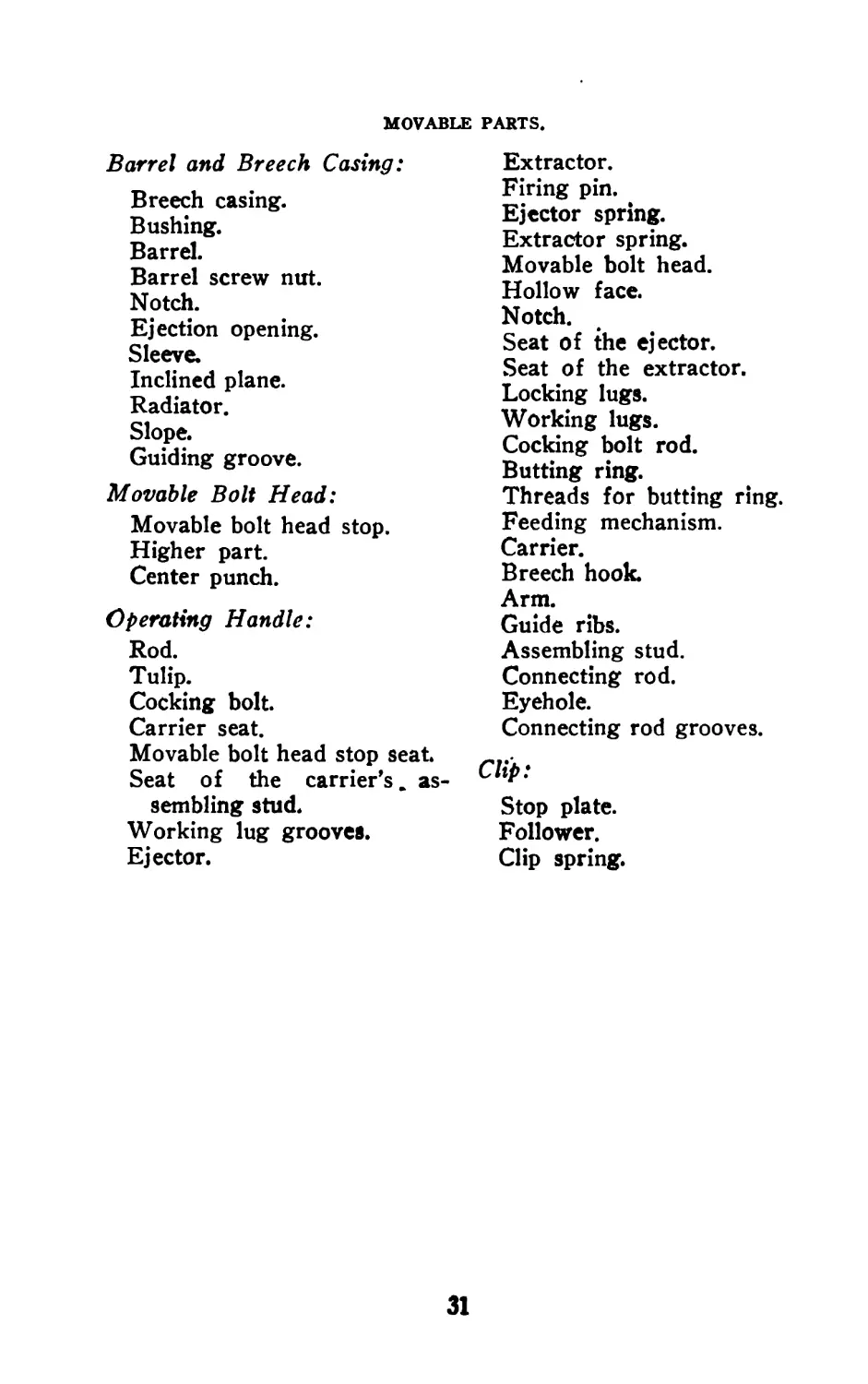
MOVABLE PARTS.
Barrel and Breech Casing:
Breech casing.
Bushing.
Barrel.
Barrel screw nut.
Notch.
Ejection opening.
Sleeve.
Inclined plane.
Radiator.
Slope.
Guiding groove.
Movable Bolt Head:
Movable bolt head stop.
Higher part.
Center punch.
Operating Handle:
Rod.
Tulip.
Cocking bolt.
Carrier seat.
Movable bolt head stop seat.
Seat of the carrier’s, as-
sembling stud.
Working lug grooves.
Ejector.
Extractor.
Firing pin.
Ejector spring.
Extractor spring.
Movable bolt head.
Hollow face.
Notch.
Seat of the ejector.
Seat of the extractor.
Locking lugs.
Working lugs.
Cocking bolt rod.
Butting ring.
Threads for butting ring.
Feeding mechanism.
Carrier.
Breech hook.
Arm.
Guide ribs.
Assembling stud.
Connecting rod.
Eyehole.
Connecting rod grooves.
Clip:
Stop plate.
Follower.
Clip spring.
31
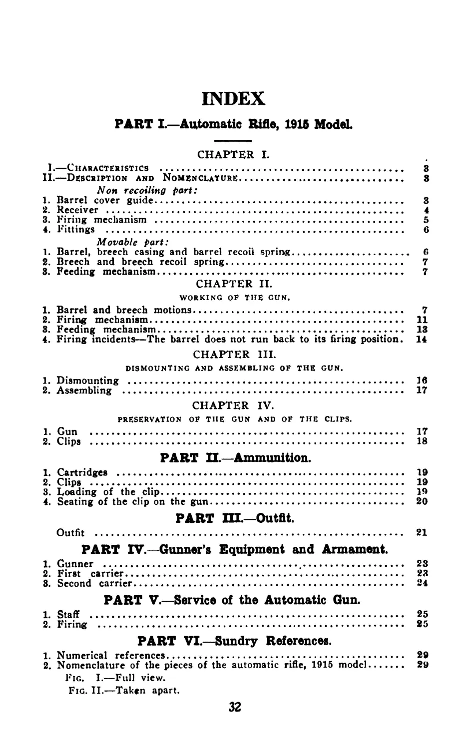
INDEX
PART I.—Automatic Rifle, 1916 Model.
CHAPTER I.
I.—Characteristics .............................................. 3
II.—Description and Nomenclature................................. 3
Non recoiling part:
1. Barrel cover guide............................................ 3
2. Receiver .................................................... 4
3. Firing mechanism ............................................ 5
4. Fittings .................................................... 6
Movable part:
1. Barrel, breech casing and barrel recoil spring................ 6
2. Breech and breech recoil spring....................... 7
8. Feeding mechanism............................................. 7
CHAPTER II.
WORKING OF THE GUN.
1. Barrel and breech motions.................................... 7
2. Firing mechanism............................................ 11
8. Feeding mechanism........................................... 13
4. Firing incidents—The barrel does not run back to its firing position. 14
CHAPTER HI.
DISMOUNTING AND ASSEMBLING OF THE GUN.
1. Dismounting ................................................. 16
2. Assembling ................................................. 17
CHAPTER IV.
PRESERVATION OF THE GUN AND OF THE CLIPS.
1. Gun ......................................................... 17
2. Clips ...................................................... 18
PART П— Ammunition.
1. Cartridges .................................................. 19
2. Clips ...................................................... 19
3. Loading of the clip......................................... 19
4. Seating of the clip on the gun.............................. 20
PART Ш.—Outfit.
Outfit ...................................................... 21
PART IV.—Gunner’s Equipment and Armament.
1. Gunner ................................................. 23
2. First carrier................................................ 23
8. Second carrier............................................... 24
PART V.—Service of the Automatic Gun.
1. Staff ....................................................... 25
2. Firing ................................................... 25
PART VI.—Sundry References.
1. Numerical references......................................... 29
2. Nomenclature of the pieces of the automatic rifle, 1915 model. 29
Fig. I.—Full view.
Fig. II.—Taken apart.
32