/

Tags: weapons
Year: 1945


Text
RESTRICTED
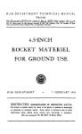
WAR DEPARTMENT TECHNICAL MANUAL
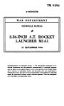
TM 9-392
This TM supersedes WDTB 9X-98, dated 10 Jan 45, and Changes No. 1, dated Apr 45.
4.5-INCH MULTIPLE
ROCKET LAUNCHERS
T66 AND T66E2
H'A R DEPARTMENT
JULY 1945
United States Government Printing Office
Washington : 1952
DK^TUICTFn
WAR DEPARTMENT
Washington 25, D. C., 14 July 1945
TM 9-392, 4.5-inch Multiple Rocket Launchers T66 and T66E2,
is published for the information and guidance of all concerned.
ГA.G. 300.7 (11 Jul 45) "I
|_O.O. 300.7/4544 J
By order of the Secretary of War:
G. C. MARSHALL,
Chief of Staff.
Official:
EDWARD F. WITSELL,
Major General,
Acting The Adjutant General.
Distribution: AGF (2); ASF (2); S Div ASF (1); T of Opn (10);
Arm к Sv Bd (1) except Rocket Bd (5); Gen к Sp Sv
Sch (1) except FA Sch (25); USMA (2); A (Ord O)
(1); CHQ (Ord O) (1); D (Ord O) (1); T/O к E
6-86 (5).
(For explanation of symbols, see FM 21-6.)
ТМ 9-392
CONTENTS
PART ONE—INTRODUCTION
Section L General .......................... 1- 2 1- 2
Й. Description and data........ 3- 6 2—10
HL Tools, parts and accessories. 7- 8 10-11
PART TWO—OPERATING INSTRUCTIONS
Section IV. General .............................. 9 12
V . Service upon receipt of
equipment ........................ 10-12 12—13
VL Controls and instruments.... 13-19 13—16
VIL Operation under usual conditions 20—24 26-27
VIIL Operation of auxiliary equipment 25 27
IX Operation under unusual
conditions........................ 26-30 28-30
X Demolition to prevent enemy
use .............................. 31-33 30-31
PART THREE—MAINTENANCE INSTRUCTIONS
Section XL General .........................34-35 32
XIL Lubrication ................; 36-37 32—37
ХЩ Preventive maintenance service.. 38-39 38
XIV. Malfunctions and corrections .... 40 39-40
XV. Tube cluster.................41-42 40-42
XVL Firing mechanism ............. 43-44 42-43
XVTL Carriage ..................... 45-46 43-44
XVHL Trails and tie rods........... 47-48 44
XIX. Control box ..................... 49 44—46
XX. Elevating mechanism .......... 50-51 46
XXL Traversing mechanism ........ 52-53 47
TM M92
PART THREE—MAINTENANCE INSTRUCTIONS—Contd.
Радо
Section XXII. Firing pedestal.............. 54 47
ХХП1. Sight bracket ................ 55 47
XXIV. Wheels .................... 56-57 47-48
PART FOUR—AUXILIARY EQUIPMENT
Section XXV. General ...................... 58 49
XXVI. Ammunition ................ 59-64 49-57
XXVII. Sighting and fire control
equipment ....................... 65-69 57-68
APPENDIX
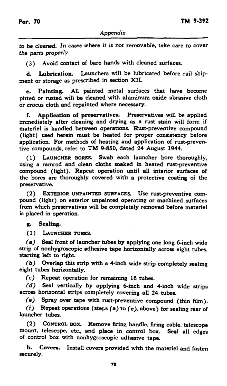
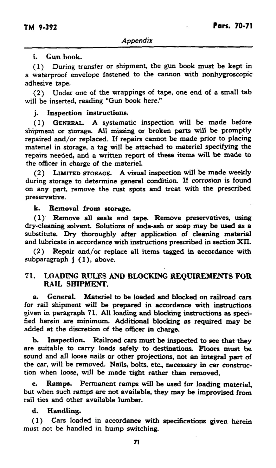
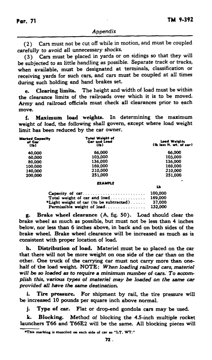
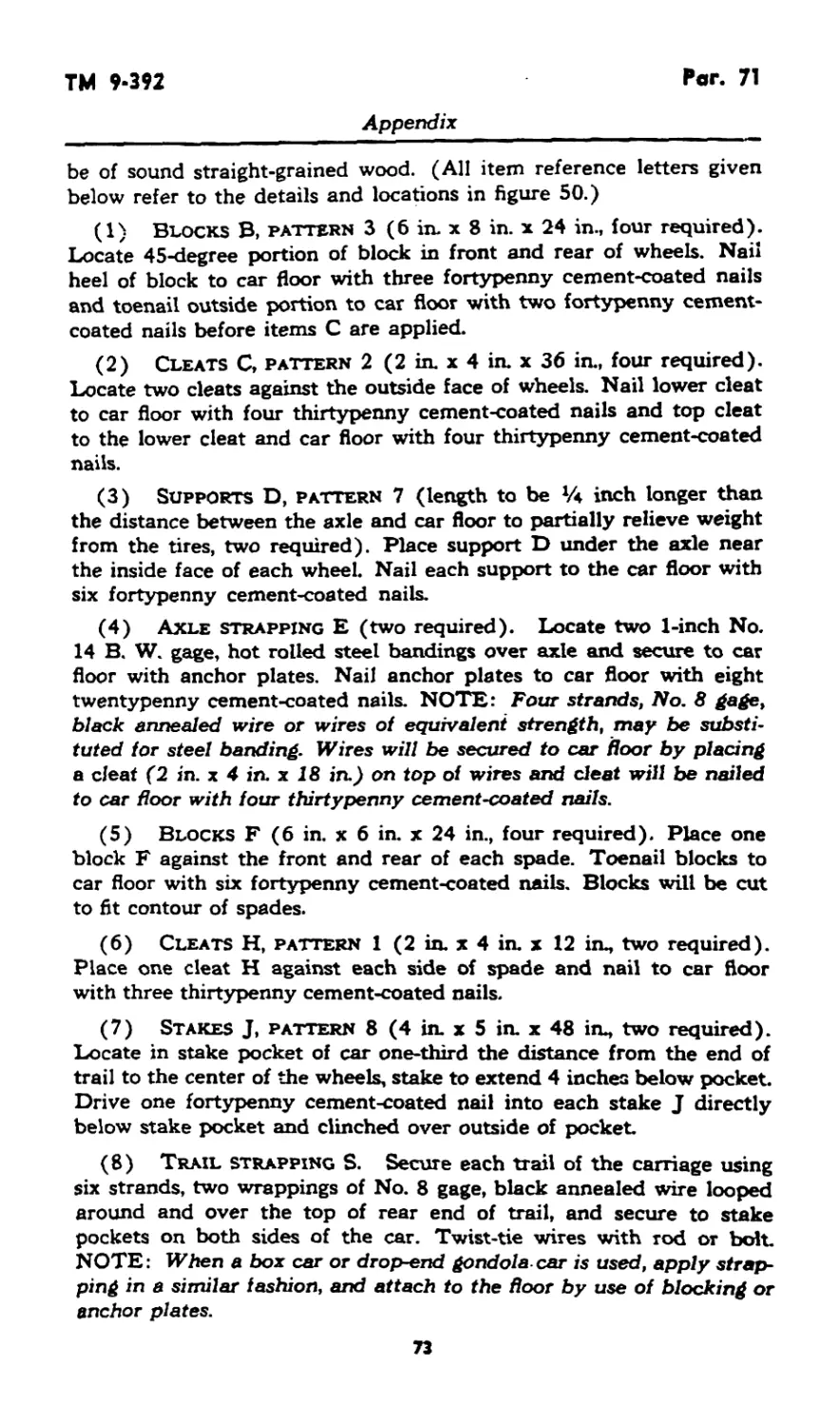
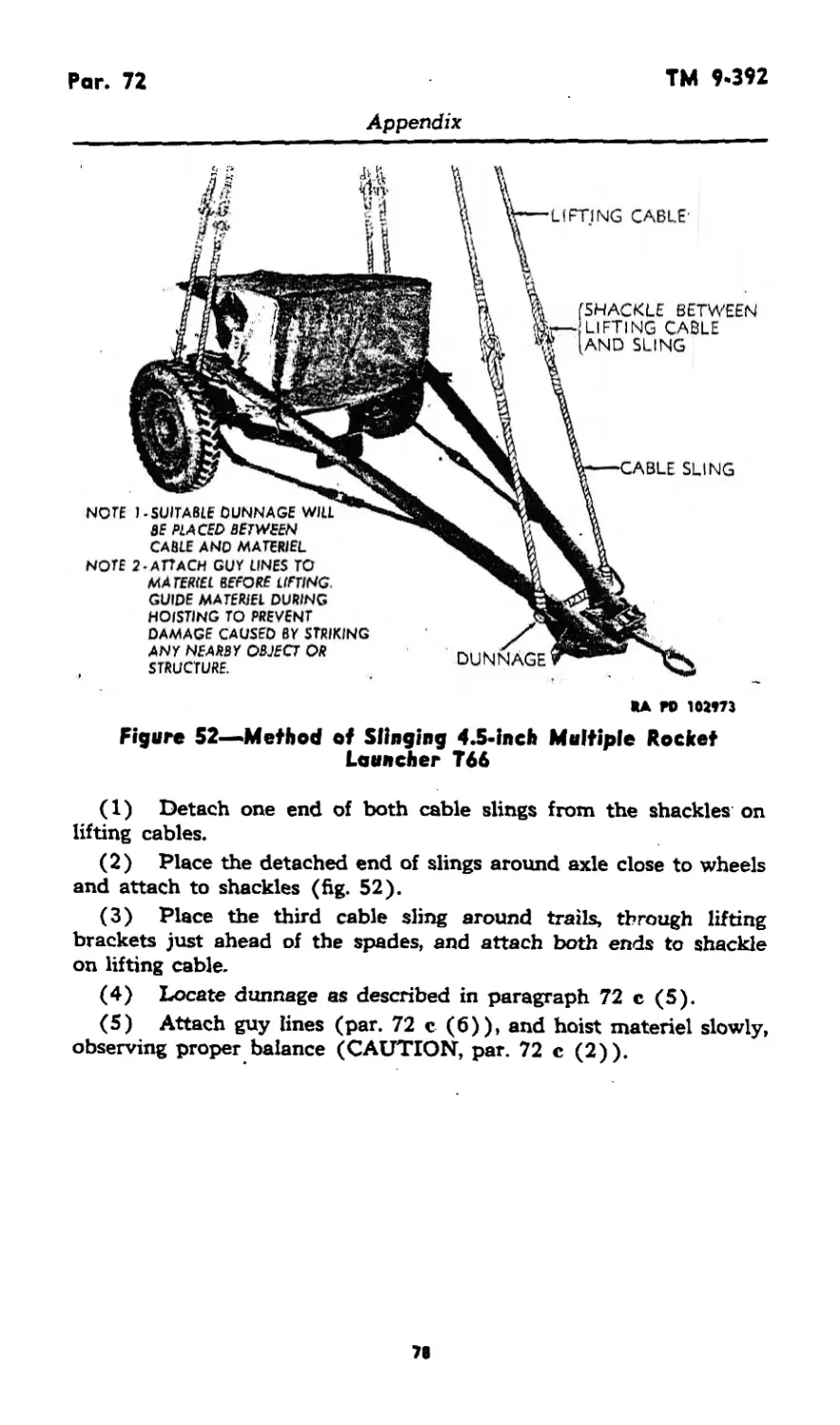
Section XXVIIL Shipment and storage...... 70-72 69—78
XXIX References ................. 73-76 79-80
Index ........................................... 81-82
ТМ МЯ
Pars. 1'2
RESTRICTED
This TM supersedes WDTB 9X-98, dated 10 Jan 45, and Changes No. 1, dated
25 Apr. 45.
PARI ONE—INTRODUCTION
Section I
GENERAL
1. SCOPE.*
a. This manual is published for the information of the using arms
and services.
b. In addition to a description of the 4.5-inch multiple rocket
launchers T66 and T66E2, this manual contains technical information
required for the identification, use, and care of the weapon, ammuni-
tion, and accessory equipment
c. In all cases where the nature of the repair, modification, or
adjustment is beyond the scope or facilities of the unit, the responsible
ordnance service should be informed so that trained personnel with
suitable tools and equipment may be provided, or proper instructions
issued.
2. RECORDS.
a. Artillery Gun Book.
(1) The Artillery Gun Book (O.O. Form 5825) is used for the
purpose of keeping an accurate record of the materiel. It must always
remain with the materiel regardless of where it may be sent The
book is divided as follows: record of assignment; battery commander’s
daily gun record; and inspector’s record of examination. This book
should be in the possession of the organization at all times, and its
completeness of records and its whereabouts are the responsibility
of the battery commander. It must also contain date of issuance of
the materiel, by whom used, and the place where issued. If a new
tube cluster is installed on the carriage, all data recorded in the old
book with reference to sights, mounts, etc, must be copied into the
new book before the old book is relinquished. If a gun book is lost,
it should be replaced at once and all entries brought up to date.
Additional copies may be obtained by requisition to Office, Chief of
Ordnance, Ordnance Service Division, Supply Branch, Attn: SPOGA-5,
Washington 25, D. C., on WD AGO Form No. 445. NOTE: Record
of assignment data must be removed and destroyed prior to entering
combat.
*To provide operating instructions with the materiel, this Technical Manual has bean
published in advance of complete technical review. Any errors or omissions will be corrected
by changes or, if extensive, by an early revision.
1
RESTRICTED
Pars. 2<3
TM 9-392
Part One—Introduction
(2) Complete instructions on how to make entries in the Artil-
lery Gun Book are contained therein. It is absolutely essential that
the gun book entries be kept complete and up to date. In order to
facilitate proper maintenance of the rocket launcher and its related
materiel (that is, carriage and associated fire control equipment) and
to avoid unnecessary duplication of repairs and maintenance, the
following additional entries are to be made in the gun book.
(a) A record of completed modification work orders. This record
should show the date completed and bear the signature of the officer
or mechanic responsible for completion of the modification.
(3) The estimated accuracy life of the tube cluster is 300 salvos.
b. Field report of accidents. When an accident involving am-
munition occurs during practice, the incident will be reported as pre-
scribed in AR 750-10 by the ordnance officer under whose supervision
the ammunition is maintained or issued. Where practicable, reports
covering malfunctions of ammunition in combat will be made to the
Chief of Ordnance, giving the type of malfunction, the type of ammu-
nition, the lot number of the complete rounds or separate-loading
components, and condition under which fired.
c. Unsatisfactory equipment report. Suggestions for improve-
ment in design, maintenance, safety, and efficiency of operation
prompted by chronic failure or malfunction of the weapon, spare
parts, or equipment should be reported on WD AGO Form No. 468,
Unsatisfactory Equipment Report, with all pertinent information
necessary to initiate corrective action. The report should be for-
warded to the Office, Chief of Ordnance, Field Service, Maintenance
Division, through command channels in accordance with instruction
No. 7 on the form. If WD AGO Form No. 468 is not available, refer
to TM 37-250 for list of data required on unsatisfactory equipment
report. Such suggestions are encouraged in order that other organiza-
tions may benefit.
Section II
DESCRIPTION AND DATA
3. GENERAL.
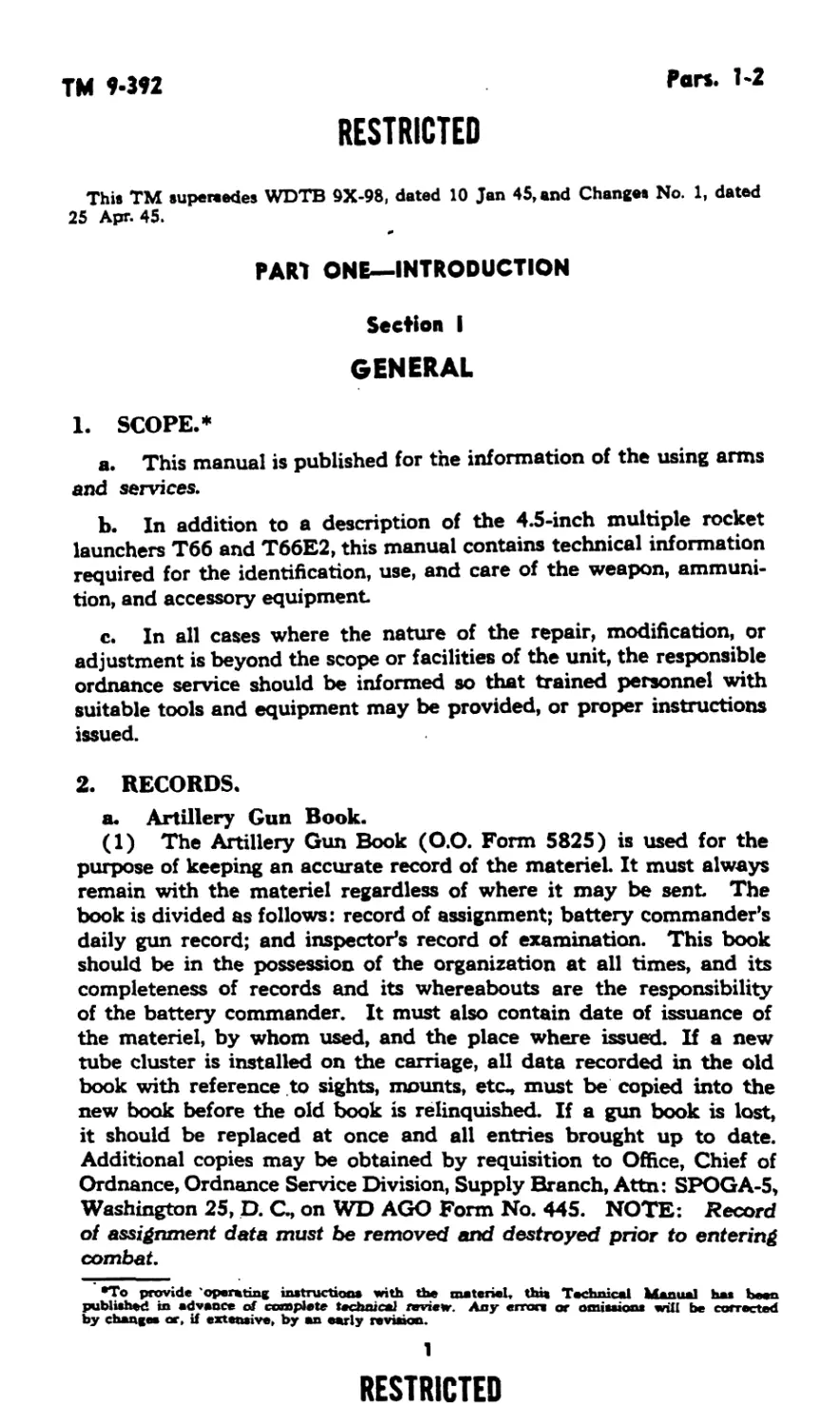
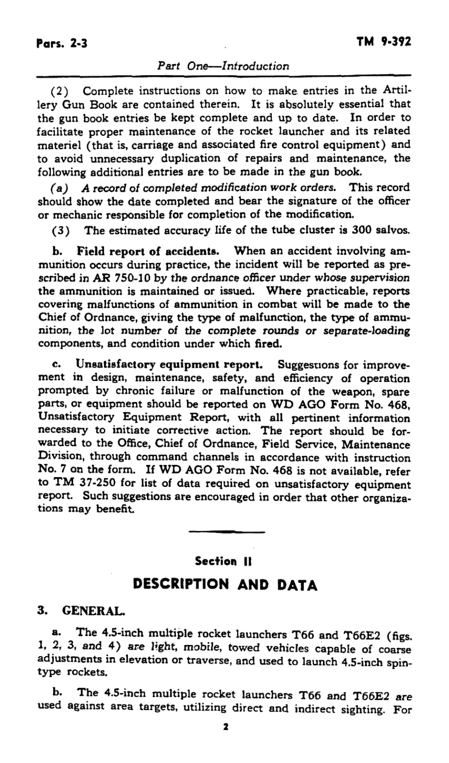
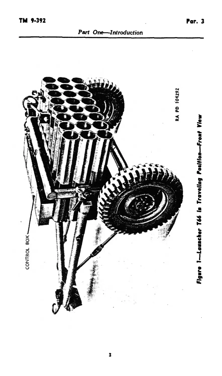
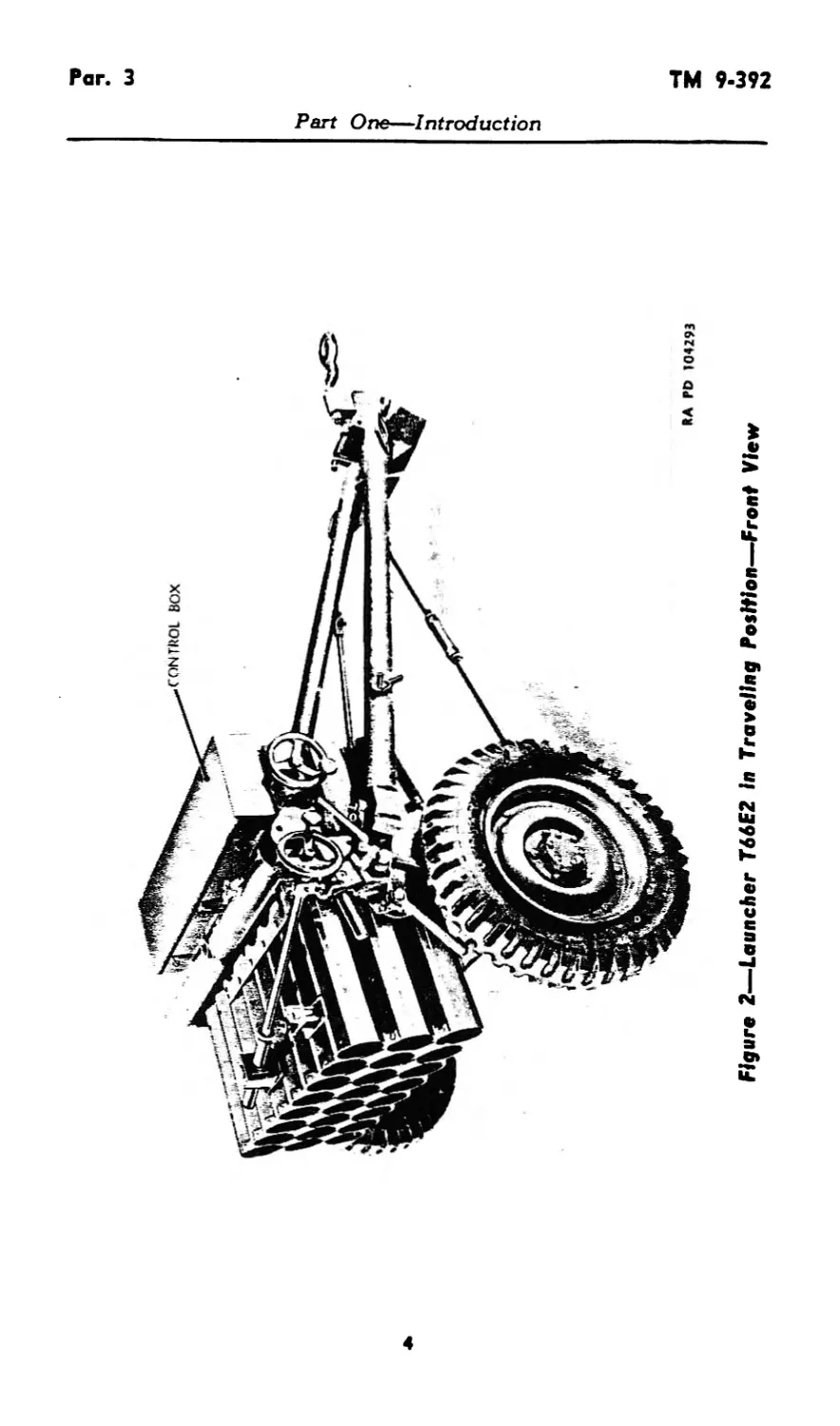
a. The 4.5-inch multiple rocket launchers T66 and T66E2 (figs.
1, 2, 3, and 4) are light, mobile, towed vehicles capable of coarse
adjustments in elevation or traverse, and used to launch 4.5-inch spin-
type rockets.
b. The 4.5-inch multiple rocket launchers T66 and T66E2 are
used against area targets, utilizing direct and indirect sighting. For
2
ТМ 9-392
Par. 3
Part Ona—Introduction
Figure 2—Launcher T66E2 In Traveling Position—Front View
О
s'
c
о
Per- 3 TM 9-392
996410 0-52
Figure 3—Laencher Т66.1п Traveling Politico—Rear View
Part One—Introduction
2
<е
<А>
ч>
кэ
Figure 4—Launcher T66E2 in Traveling Position—Rear View
Par. 3 TM 9-392
ТМ 9-392
Par. 3
Part One—Introduction
Figure 5—Launcher T66 In Firing Position—Front View
7
Par. 3
TM 9-392
Part One—Introduction
RA M> 104297
Figure 6—Nameplate on Launcher T66
RA PD 104298
Figure 7—Nameplate on Launcher T66E2
8
ТМ 9-392
Pars. 3-6
Part One—Introduction
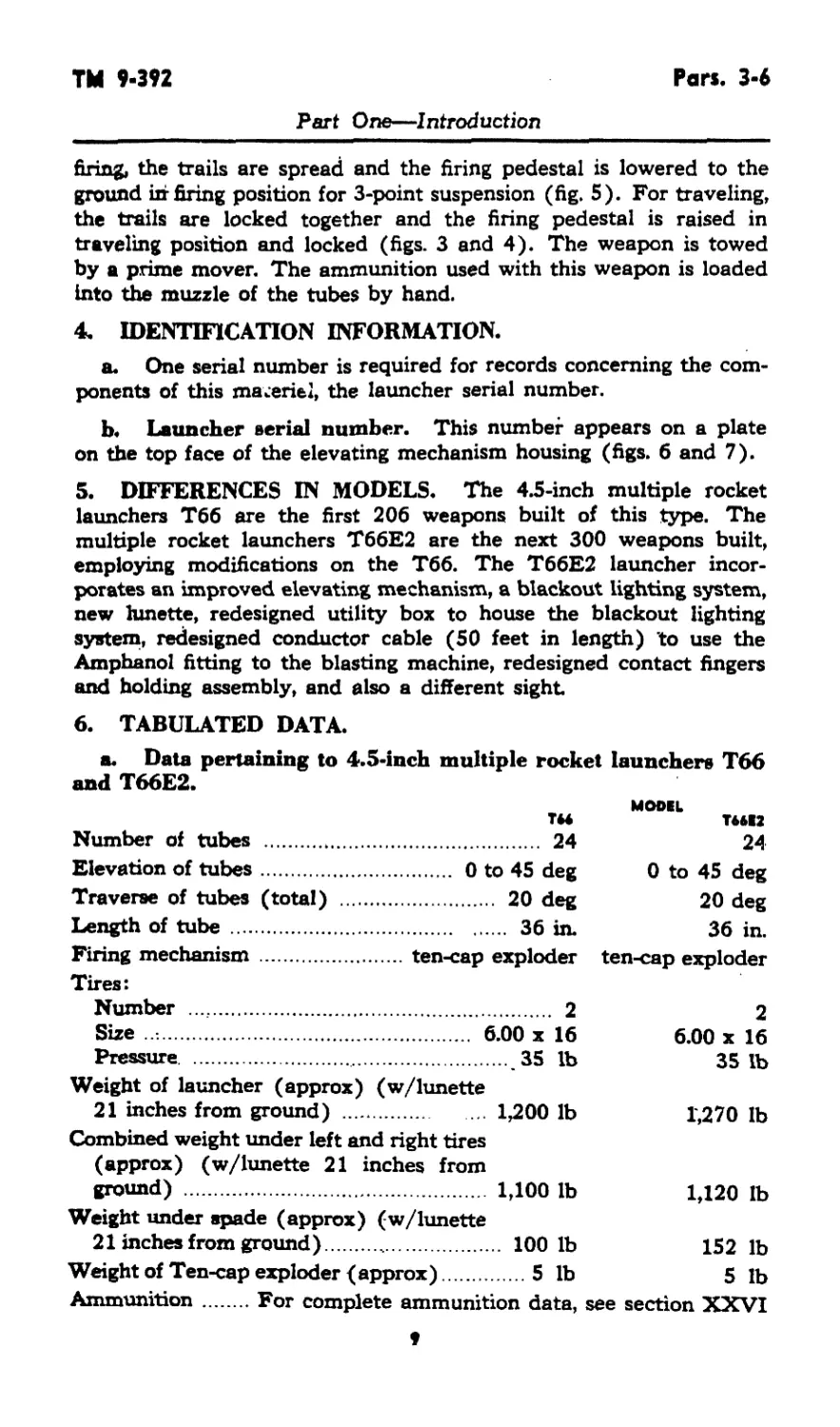
firing, the trails are spread and the firing pedestal is lowered to the
ground in firing position for 3-point suspension (fig. 5). For traveling,
the trails are locked together and the firing pedestal is raised in
traveling position and locked (figs. 3 and 4). The weapon is towed
by a prime mover. The ammunition used with this weapon is loaded
into the muzzle of the tubes by hand.
4. IDENTIFICATION INFORMATION.
a. One serial number is required for records concerning the com-
ponents of this materiel, the launcher serial number.
b. Launcher serial number. This number appears on a plate
on the top face of the elevating mechanism housing (figs. 6 and 7).
5. DIFFERENCES IN MODELS. The 4.5-inch multiple rocket
launchers Тбб are the first 206 weapons built of this type. The
multiple rocket launchers T66E2 are the next 300 weapons built,
employing modifications on the Тбб. The T66E2 launcher incor-
porates an improved elevating mechanism, a blackout lighting system,
new lunette, redesigned utility box to house the blackout lighting
system, redesigned conductor cable (50 feet in length) to use the
Amphanol fitting to the blasting machine, redesigned contact fingers
and holding assembly, and also a different sight
6. TABULATED DATA.
a. Data pertaining to 4.5-inch multiple rocket launchers T66
and T66E2.
TH Number of tubes 24 Elevation of tubes 0 to 45 deg Traverse of tubes (total) 20 deg Length of tube 36 in. Firing mechanism ten-cap exploder Tires: MODEL T64E2 24 0 to 45 deg 20 deg 36 in. ten-cap exploder
Number 2 Size 6.00 x 16 Pressure 35 lb 2 6.00 x 16 35 lb
Weight of launcher (approx) (w/lunette 21 inches from ground) 1,200 lb Combined weight under left and right tires (approx) (w/lunette 21 inches from ground) 1,100 lb Weight under spade (approx) (w/lunette 21 inches from ground) 100 lb Weight of Ten-cap exploder (approx) 5 lb 1,270 lb 1,120 lb 152 lb 5 lb
Ammunition.....For complete ammunition data, see section XXVI
Pars. 6-7
TM 9-392
Part One—Introduction
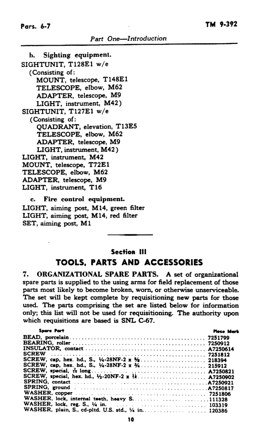
b. Sighting equipment.
SIGHTUNIT, T128E1 w/e
(Consisting of:
MOUNT, telescope, T148E1
TELESCOPE, elbow, M62
ADAPTER, telescope, M9
LIGHT, instrument, M42)
SIGHTUNIT, T127E1 w/e
(Consisting of:
QUADRANT, elevation, T13E5
TELESCOPE, elbow, M62
ADAPTER, telescope, M9
LIGHT, instrument, M42 )
LIGHT, instrument, M42
MOUNT, telescope, T72E1
TELESCOPE, elbow, M62
ADAPTER, telescope, M9
LIGHT, instrument, T16
c. Fire control equipment.
LIGHT, aiming post, M14, green filter
LIGHT, aiming post, M14, red filter
SET, aiming post, Ml
Section III
TOOLS, PARTS AND ACCESSORIES
7. ORGANIZATIONAL SPARE PARTS. A set of organizational
spare parts is supplied to the using arms for field replacement of those
parts most likely to become broken, worn, or otherwise unserviceable.
The set will be kept complete by requisitioning new parts for those
used. The parts comprising the set are listed below for information
only; this list will not be used for requisitioning. The authority upon
which requisitions are based is SNL C-67.
Spore Port Heee Mark
BEAD, porcelain............................................ 7251799
BEARING, roller............................................ 7250912
INSULATOR, contact.........................................A7250614
SCREW ..................................................... 7251812
SCREW, cap, hex. hd., S., Vi-28NF-2 x %.................... 218394
SCREW, cap, hex. hd., S., »4-28NF-2 x Уч...................215912
SCREW, special, Л long......................................A7250821
SCREW, special, hex. hd., Vi-20NF-2 x H.....................A72S0902
SPRING, contact ............................................A7250921
SPRING, ground ............................................ A7250817
WASHER, copper............................................ 7251806
WASHER, lock, internal teeth, heavy S......................111328
WASHER, lock, reg. S., lA in............................... 103319
WASHER, plain, S., cd-pltd. U.S. std., % in................ 120386
10
ТМ 9-392
Par. 8
Part One—Introduction
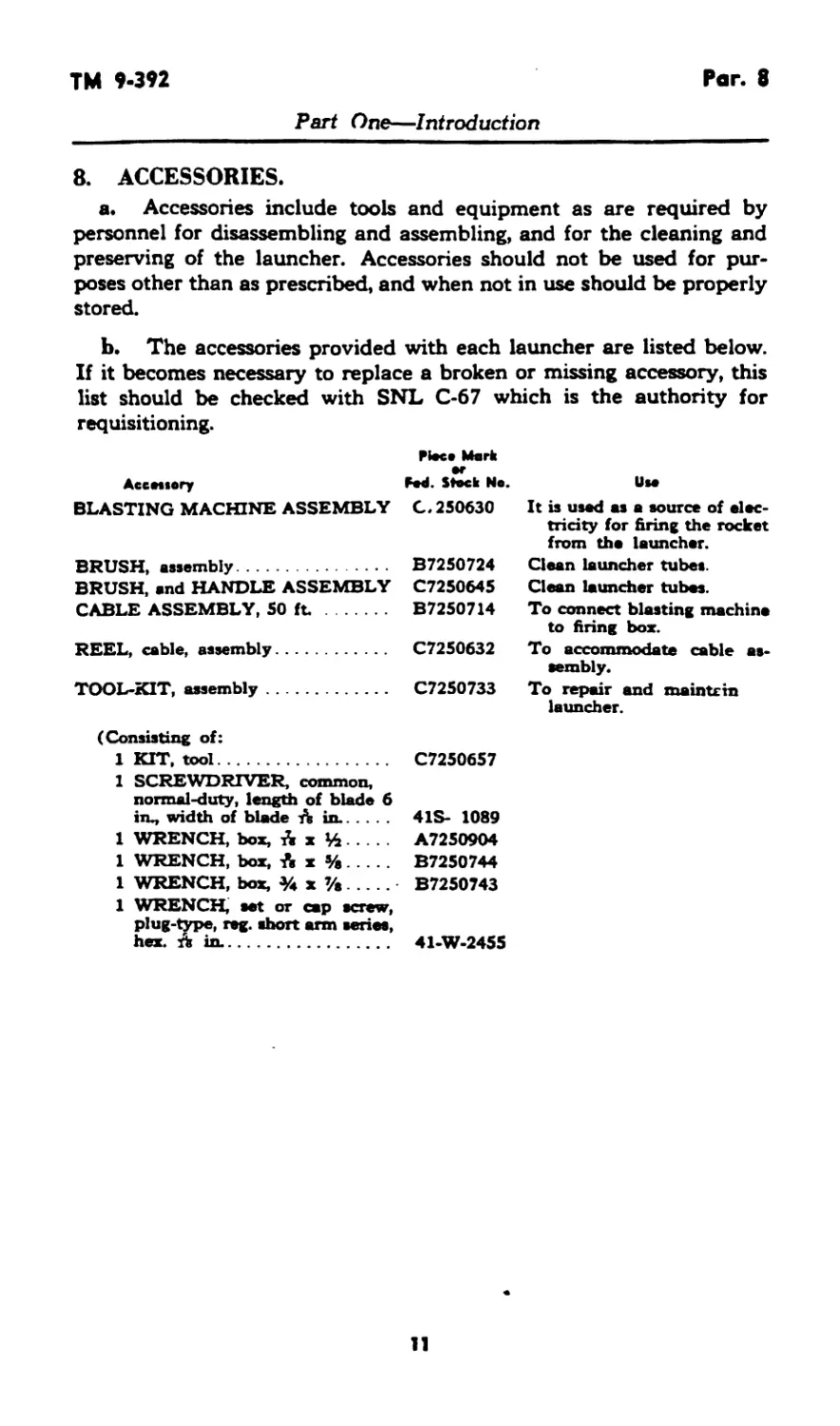
8. ACCESSORIES.
a. Accessories include tools and equipment as are required by
personnel for disassembling and assembling, and for the cleaning and
preserving of the launcher. Accessories should not be used for pur-
poses other than as prescribed, and when not in use should be properly
stored.
b. The accessories provided with each launcher are listed below.
If it becomes necessary to replace a broken or missing accessory, this
list should be checked with SNL C-67 which is the authority for
requisitioning.
Piece Merk
Accetiory Fed. Stock Na. Ute
BLASTING MACHINE ASSEMBLY C.250630 It is used as a source of elec- tricity for firing the rocket from the launcher.
BRUSH, assembly B7250724 Clean launcher tubes.
BRUSH, «nd HANDLE ASSEMBLY C7250645 Clean launcher tubes.
CABLE ASSEMBLY, 50 ft. B7250714 To connect blasting machine to firing box.
REEL, cable, assembly C7250632 To accommodate cable as- sembly.
TOOL-KIT, assembly C7250733 To repair and maintain launcher.
(Consisting of:
1 KIT, tool................. C7250657
1 SCREWDRIVER, common,
normal-duty, length of blade 6
iru, width of blade A in.. 4 IS- 1089
1 WRENCH, box, A x %... A7250904
1 WRENCH, box, A x %... B7250744
1 WRENCH, box, % x %... B7250743
1 WRENCH, set or cap screw,
plug-type, reg. short arm series,
hex. A in.............. 41-W-2455
11
Pars. 9-11
TM 9-392
PART TWO—OPERATING INSTRUCTIONS
Section IV
GENERAL
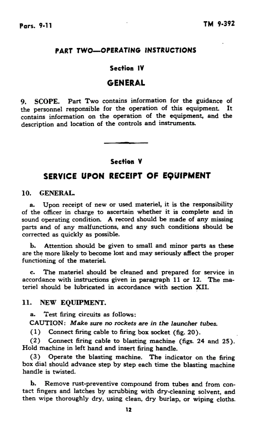
9. SCOPE. Part Two contains information for the guidance of
the personnel responsible for the operation of this equipment It
contains information on the operation of the equipment, and the
description and location of the controls and instruments.
Section V
SERVICE UPON RECEIPT OF EQUIPMENT
10. GENERAL.
a. Upon receipt of new or used materiel, it is the responsibility
of the officer in charge to ascertain whether it is complete and in
sound operating condition. A record should be made of any missing
parts and of any malfunctions, and any such conditions should be
corrected as quickly as possible.
b. Attention should be given to small and minor parts as these
are the more likely to become lost and may seriously affect the proper
functioning of the materiel
c. The materiel should be cleaned and prepared for service in
accordance with instructions given in paragraph 11 or 12. The ma-
teriel should be lubricated in accordance with section XII.
11. NEW EQUIPMENT.
a. Test firing circuits as follows:
CAUTION; Make sure no rockets are in the launcher tubes.
(1) Connect firing cable to firing box socket (fig. 20).
(2) Connect firing cable to blasting machine (figs. 24 and 25).
Hold machine in left hand and insert firing handle.
(3) Operate the blasting machine. The indicator on the firing
box dial should advance step by step each time the blasting machine
handle is twisted.
b. Remove rust-preventive compound from tubes and from con-
tact fingers and latches by scrubbing with dry-cleaning solvent, and
then wipe thoroughly dry, using clean, dry burlap, or wiping cloths.
12
TM 9-392
Pars. 11-16
Part Two—’Operating Instructions
c. Apply a light coat of preservative lubricating oil (special) to
tubes and all base metal surfaces. Apply a few drops of preservative
lubricating oil (special) to release assemblies.
12. USED EQUIPMENT.
a. Test firing circuits as outlined in paragraph Ila and remove
rust-preventive compound as outlined in paragraph 11 b.
b. Inspect contact fingers and latches to be sure they are not
broken and are in operating condition.
Section VI
CONTROLS AND INSTRUMENTS
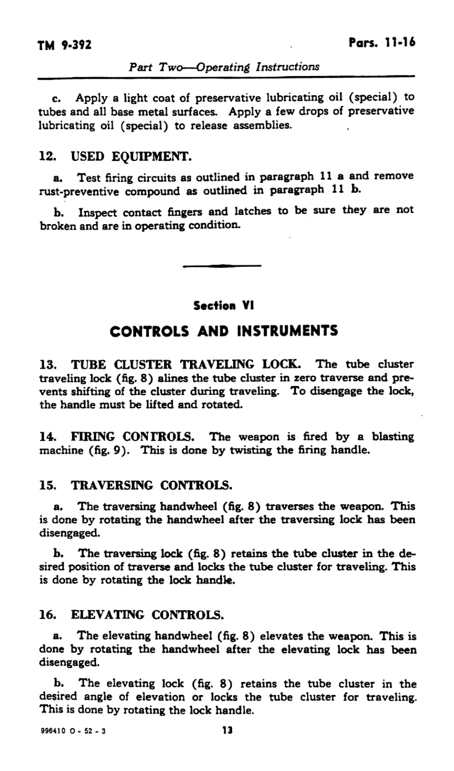
13. TUBE CLUSTER TRAVELING LOCK. The tube cluster
traveling lock (fig. 8) alines the tube cluster in zero traverse and pre-
vents shifting of the cluster during traveling. To disengage the lock,
the handle must be lifted and rotated.
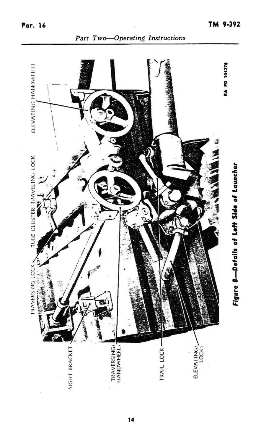
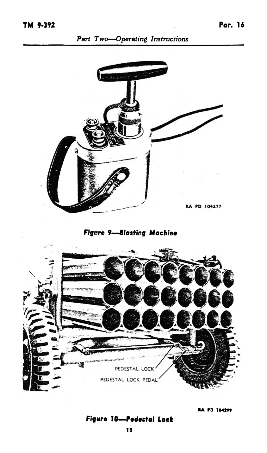
14. FIRING CONTROLS. The weapon is fired by a blasting
machine (fig. 9). This is done by twisting the firing handle.
15. TRAVERSING CONTROLS.
a. The traversing handwheel (fig. 8) traverses the weapon. This
is done by rotating the handwheel after the traversing lock has been
disengaged.
b. The traversing lock (fig. 8) retains the tube cluster in the de-
sired position of traverse and locks the tube cluster for traveling. This
is done by rotating the lock handle.
16. ELEVATING CONTROLS.
a. The elevating handwheel (fig. 8) elevates the weapon. This is
done by rotating the handwheel after the elevating lock has been
disengaged.
b. The elevating lock (fig. 8) retains the tube cluster in the
desired angle of elevation or locks the tube cluster for traveling.
This is done by rotating the lock handle.
996410 0 - 52 -3
13
RA PD 104271
Figure 8—Details of Loft Side of Launcher
ТМ 9-392
Par. 16
Part Two—Operating Instructions
Figere 9—Blasting Machine
SA ГЭ
Figure 10—Pedestal Lock
15
Pan. 17-20
TM 9-392
Part Two—Operating Instructions
17. PEDESTAL CONTROLS.
a. The locking bar latches (figs. 3 and 4) keep the pedestal
locking bars taut. This is done by rotating the latch levers.
b. The pedestal lock (fig. 10) retains the pedestal in firing posi-
tion. The lock is released by pressing the lock pedal.
18. TRAIL CONTROLS.
a. The trail traveling lock (figs. 3 and 4) fastens the trails to-
gether in traveling position. This is done by rotating the lock lever
after the traveling lock latch has been released.
b. The trail traveling lock latch (figs. 3 and 4) retains the trail
traveling lock in the closed position. The latch is released by pulling
the knob and rotating it
c. The trail locks (fig. 8) retain the trails in firing position. This
is done by rotating the lock handle.
19. INSTRUMENTS. The firing box consists of a dial with 24
numbered graduations and an indicator which shows the tube to be
fired (figs. 22 and 23).
Section VII
OPERATION UNDER USUAL CONDITIONS
20. TO PLACE LAUNCHER IN FIRING POSITION.
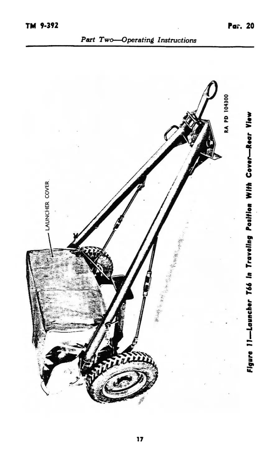
a. Remove launcher cover (fig. 11) and place it out of the way.
Select terrain as level as possible on which to emplace the weapon.
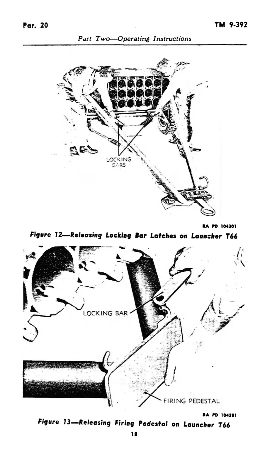
b. Unscrew locking bar latches (fig. 12). Release firing pedestal
locking bars from firing pedestal, and lower pedestal to ground (fig.
13). Place bars in their brackets on the trails.
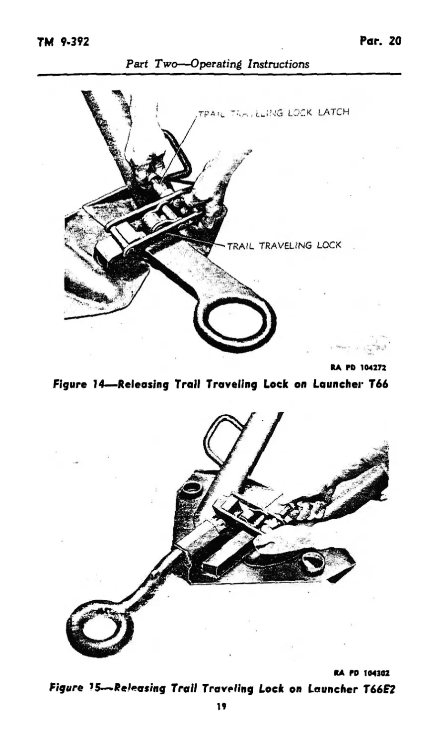
c. Disengage the trail traveling lock to release the trails (figs. 14
and 15).
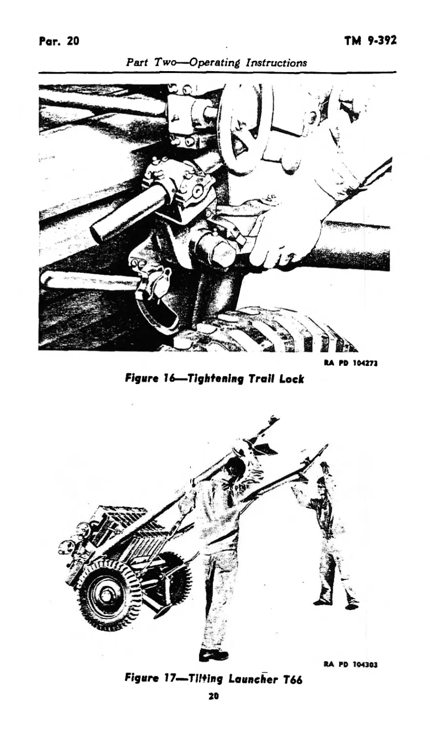
d. Spread the trails and lock them in firing position with the
trail locks (fig. 16).
e. Tilt the launcher forward (fig. 17). The firing pedestal will
fall into firing position. A click will be heard when the pedestal
lock engages. Lower trails to ground.
14
RA rD 104300
Figure 11—Launcher T66 In Traveling Petition With Cover—Rear View
5*
I
r
Par. 20
TM 9-392
Part Two—Operating Instructions
RA PO 164301
Figure 12—Releasing Locking Bar Latches on Launcher T66
RA PD 1042S1
Figure 13—Releasing Firing Pedestal on Launcher T66
18
ТМ 9-392
Par. 20
Part Two—Operating Instructions
RA PD 104272
Figure 14—Releasing Trail Traveling Lock on Launcher T66
*A ГО 104302
Figure 15-~Releashig Trail Traveling Lock on Launcher T66E2
19
Par. 20
TM 9-392
Part Two—Operating Instructions
RA M> 104273
Figure 16—Tightening Trail Lock
Figure 17—Tilting Launcher T66
20
TM 9'392
Pan 20
Part Two—Operating Instructions
RA ГО 104275
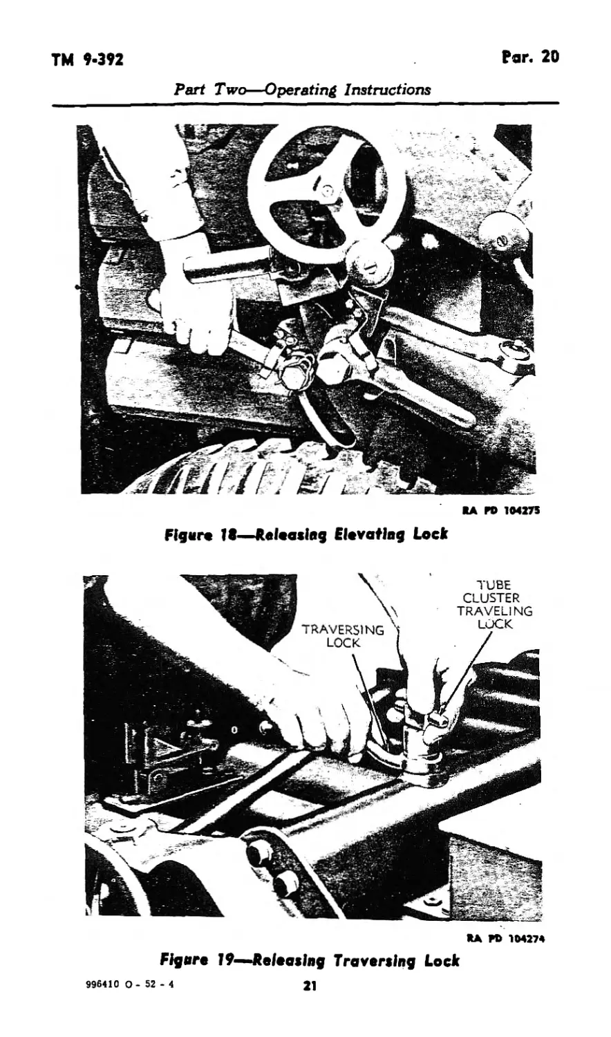
Figure 18—Relaaslng El* voting Lock
RA M> 104274
Figure 19~Jteleoslng Traversing Lock
996410 0- 52 -4
21
Par. 20*21
TM 9-392
Part Two—Operating Instructions
*A ГО 104304
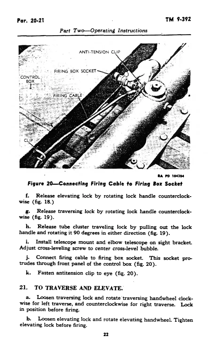
Figure 20—«Connecting Firing Cable to Firing Box Socket
f. Release elevating lock by rotating lock handle counterclock-
wise (fig. 18.)
g. Release traversing lock by rotating lock handle counterclock-
wise (fig. 19).
h. Release tube cluster traveling lock by pulling out the lock
handle and rotating it 90 degrees in either direction (fig. 19).
i. Install telescope mount and elbow telescope on sight bracket.
Adjust cross-leveling screw to center cross-level bubble.
j. Connect firing cable to firing box socket. This socket pro-
trudes through front panel of the control box (fig. 20).
k. Fasten antitension clip to eye (fig. 20).
21. TO TRAVERSE AND ELEVATE.
a. Loosen traversing lock and rotate traversing hand wheel clock-
wise for left traverse, and counterclockwise for right traverse. Lock
in position before firing.
b. Loosen elevating lock and rotate elevating handwheel. Tighten
elevating lock before firing.
22
ТМ 9-392
Par. 21
Part Two—Operating Instructions
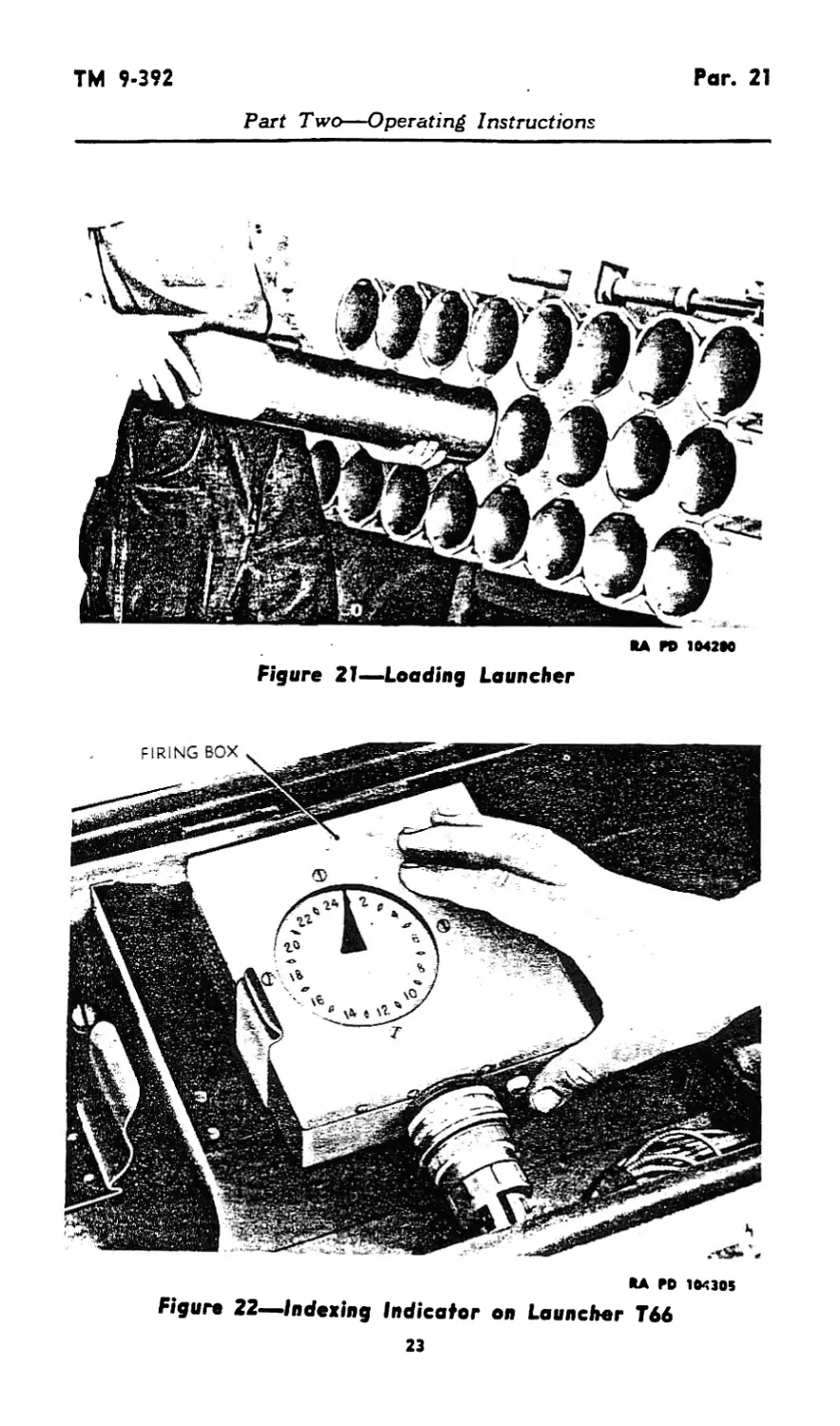
Figure 21—Loading Launcher
RA PO 104305
Figure 22^indeting Indicator on Launcher T66
23
Par. 21
TM 9-3*2
Part Two—Operating Instructions
кд га 104Ш
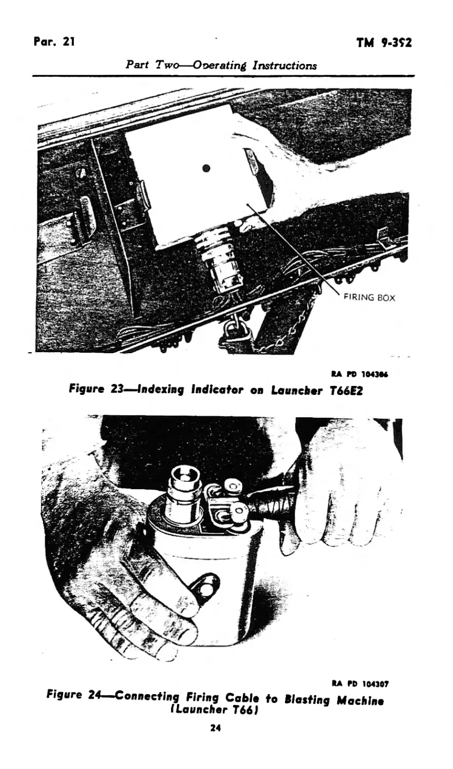
Figure 23—Indexing Indicator on Launcher T66F2
RA ГО 104307
Figure 24—Connecting Firing Cable to Blasting Machine
(Launcher T66J
24
ТМ 9*392
Par. 22
Part Two—Operating Instructions
RA W> 104308
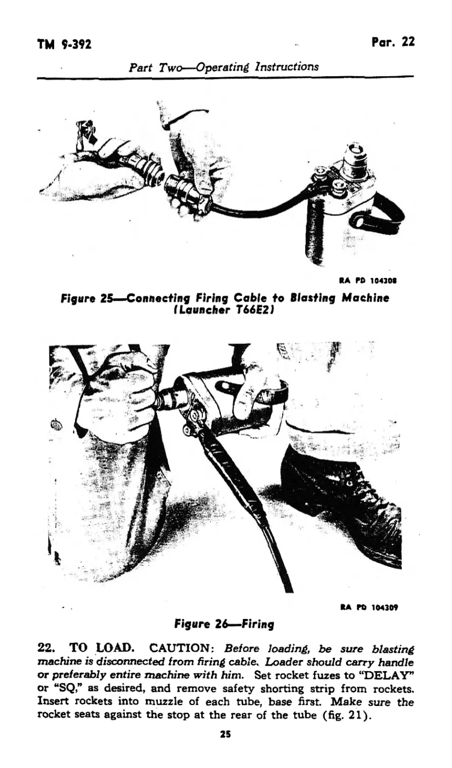
Figure 25—Connecting Firing Coble to Blasting Machine
(Launcher T66E2J
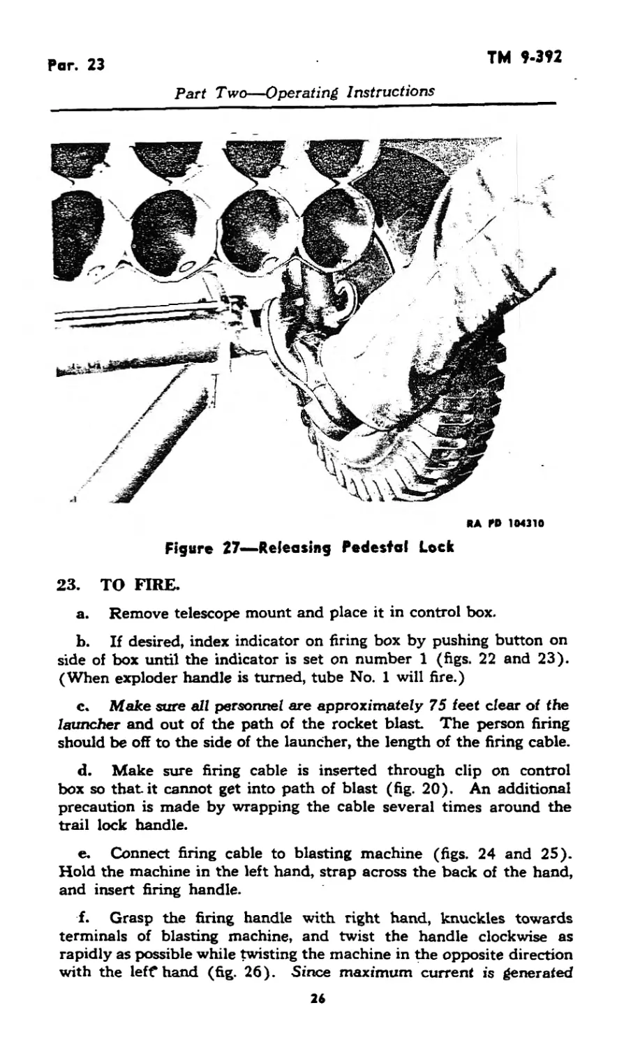
RA ГО 104309
Figure 26—Firing
22. TO LOAD. CAUTION: Before loading, be sure blasting
machine is disconnected from firing cable. Loader should carry handle
or preferably entire machine with him. Set rocket fuzes to “DELAY”
or “SQ,” as desired, and remove safety shorting strip from rockets.
Insert rockets into muzzle of each tube, base first. Make sure the
rocket seats against the stop at the rear of the tube (fig. 21).
2S
Par. 23
TM 9-392
Part Two—Operating Instructions
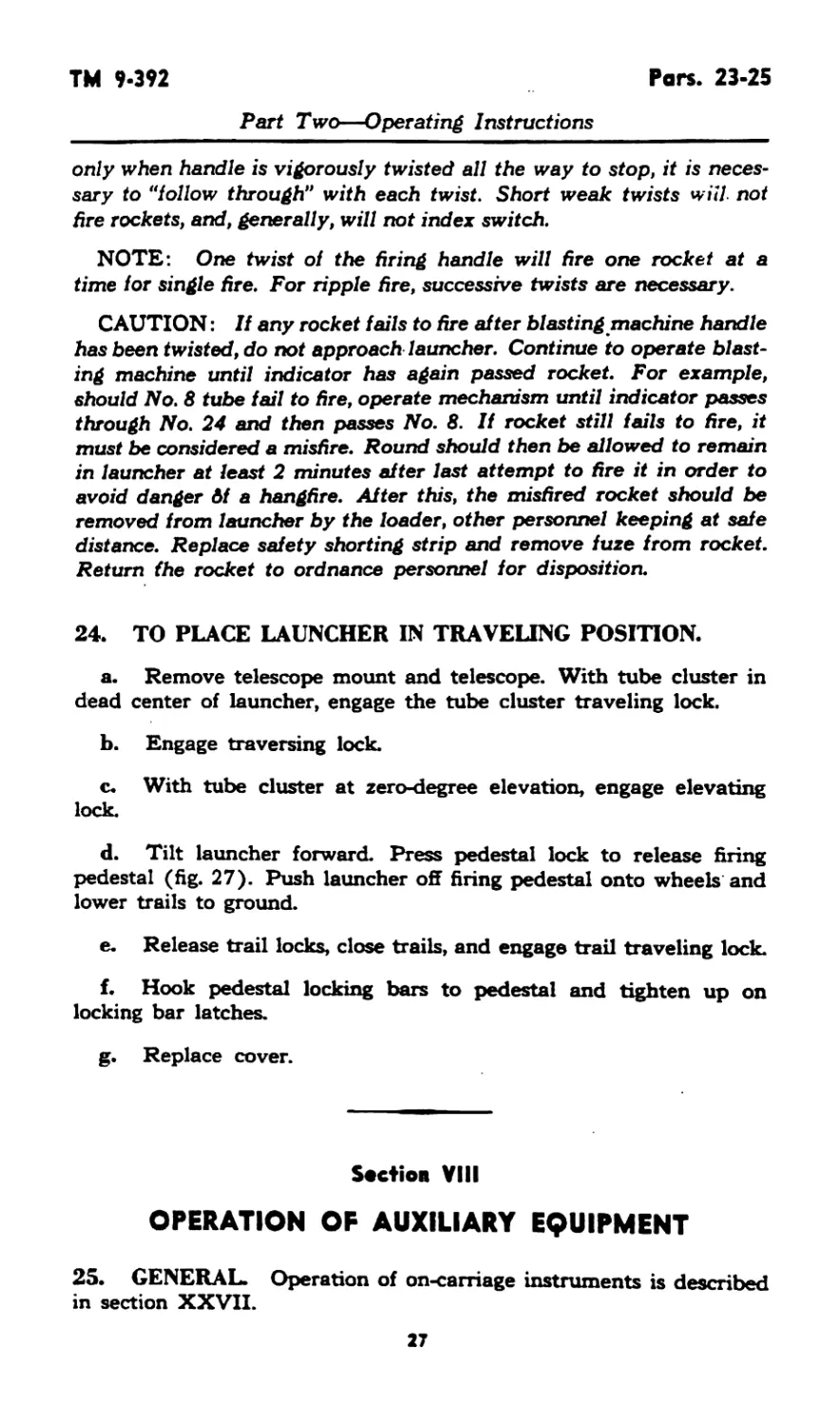
RA И» 104310
Figure 27—Releasing Pedestal Lock
23. TO FIRE.
a. Remove telescope mount and place it in control box.
b. If desired, index indicator on firing box by pushing button on
side of box until the indicator is set on number 1 (figs. 22 and 23).
(When exploder handle is turned, tube No. 1 will fire.)
c. Make sure all personnel are approximately 75 feet clear of the
launcher and out of the path of the rocket blast. The person firing
should be off to the side of the launcher, the length of the firing cable.
d. Make sure firing cable is inserted through clip on control
box so that it cannot get into path of blast (fig. 20). An additional
precaution is made by wrapping the cable several times around the
trail lock handle.
e. Connect firing cable to blasting machine (figs. 24 and 25).
Hold the machine in the left hand, strap across the back of the hand,
and insert firing handle.
f. Grasp the firing handle with right hand, knuckles towards
terminals of blasting machine, and twist the handle clockwise as
rapidly as possible while twisting the machine in the opposite direction
with the left* hand (fig. 26). Since maximum current is generated
26
TM 9*392
Pars. 23*25
Part Two—Operating Instructions
only when handle is vigorously twisted all the way to stop, it is neces-
sary to "follow through" with each twist. Short weak twists will- not
fire rockets, and, generally, will not index switch.
NOTE: One twist of the firing handle will fire one rocket at a
time for single fire. For ripple fire, successive twists are necessary.
CAUTION: If any rocket fails to fire after blasting machine handle
has been twisted, do not approach launcher. Continue to operate blast-
ing machine until indicator has again passed rocket. For example,
should No. 8 tube fail to fire, operate mechanism until indicator passes
through No. 24 and then passes No. 8. If rocket still fails to fire, it
must be considered a misfire. Round should then be allowed to remain
in launcher at least 2 minutes after last attempt to fire it in order to
avoid danger Af a hangfire. After this, the misfired rocket should be
removed from launcher by the loader, other personnel keeping at safe
distance. Replace safety shorting strip and remove fuze from rocket.
Return the rocket to ordnance personnel for disposition.
24. TO PLACE LAUNCHER IN TRAVELING POSITION.
a. Remove telescope mount and telescope. With tube cluster in
dead center of launcher, engage the tube cluster traveling lock.
b. Engage traversing lock.
c. With tube cluster at zero-degree elevation, engage elevating
lock.
d. Tilt launcher forward. Press pedestal lock to release firing
pedestal (fig. 27). Push launcher off firing pedestal onto wheels and
lower trails to ground.
e. Release trail locks, close trails, and engage trail traveling lock.
f. Hook pedestal locking bars to pedestal and tighten up on
locking bar latches.
g. Replace cover.
Section VIII
OPERATION OF AUXILIARY EQUIPMENT
25. GENERAL. Operation of on-carriage instruments is described
in section XXVII.
27
Pers. 26-29
TH 9-392
Part Two—Operating Instructions
Section IX
OPERATION UNDER UNUSUAL CONDITIONS
26. GENERAL.
a. Since rockets may not be fired outside their temperature
ranges, operation under extreme temperature conditions is not per-
mitted.
b. Refer to section XII for lubrication under unusual conditions.
27. EXCESSIVELY MOIST OR SALTY ATMOSPHERE.
a. When the materiel is not in active use, the unpainted metal
parts should be covered with a film of rust-preventive compound
(light). The bore of the metal tubes should be kept oiled and all
parts should be inspected daily for traces of the formation of rust.
The materiel should be kept covered with tarpaulins as much as
possible.
b. In excessively salty atmosphere, the oil or rust-preventive
compound (light) used should be changed often, as the salt has a
tendency to emulsify the oil and destroy its rust-preventive qualities.
c. Check carriage frequently for chipped or cracked paint.
28. EXCESSIVELY SANDY OR DUSTY CONDITIONS.
a. If considerable sand or dust is present when the launchers are
operated, the lubricant should be removed from the moving parts
and these parts should remain dry until the action is over. If the
surfaces are dry, there is less wear than when coated with a lubricant
contaminated with grit.
b. Keep materiel covered with tarpaulins as much as possible.
c. Materiel must be cleaned frequently, as sanfl <>r dust arid
lubricant act as an abrasive.
29. COLD CLIMATES WITHIN TEMPERATURE RANGES.
a. Preparing a weapon for cold climate consists of inspecting and
placing the launcher in good mechanical condition, cleaning, and lubri-
cating with cold-weather lubricants, and frequent exercising.
b. The materiel should be inspected to see that all moving parts
operate freely and without binding.
c. In cold climates it is essential that all moving parts be kept
absolutely free of moisture.
28
TM 9-392
Par. 29
Part Two—Operating Instructions
d. Clean and lubricate all parts, but do not use excess lubricant,
because it may solidify to such an extent as to cause sluggish move-
ment.
e. When launchers are in the open, cover with tarpaulins or other
suitable material, if possible.
f. When tube cluster and carriage are transferred from the out-
side into a heated building, wipe dry with clean cloths, and clean and
oil metal parts immediately to prevent condensation of moisture.
g. Before applying the cold-weather lubricants, the materiel
should be thoroughly cleaned and all old lubricants removed.
h. Tube cleaning.
(1) Rifle bore cleaner. When cleaning the inside of the tubes
with rifle-bore cleaner at temperatures below 0°F, wipe the tubes dry
and oil. Do not allow the rifle-bore cleaner to remain in the tubes as
freezing of the cleaner in the tubes may make firing dangerous. The
third day after firing, use dry-cleaning solvent, if available, to remove
the old film. When rifle-bore cleaner can no longer be used due to
freezing, the tubes must either be warmed before continuing to use
the bore cleaner or a soda-ash or soap solution must be used. Do not
add antifreezes to ride-bore cleaner.
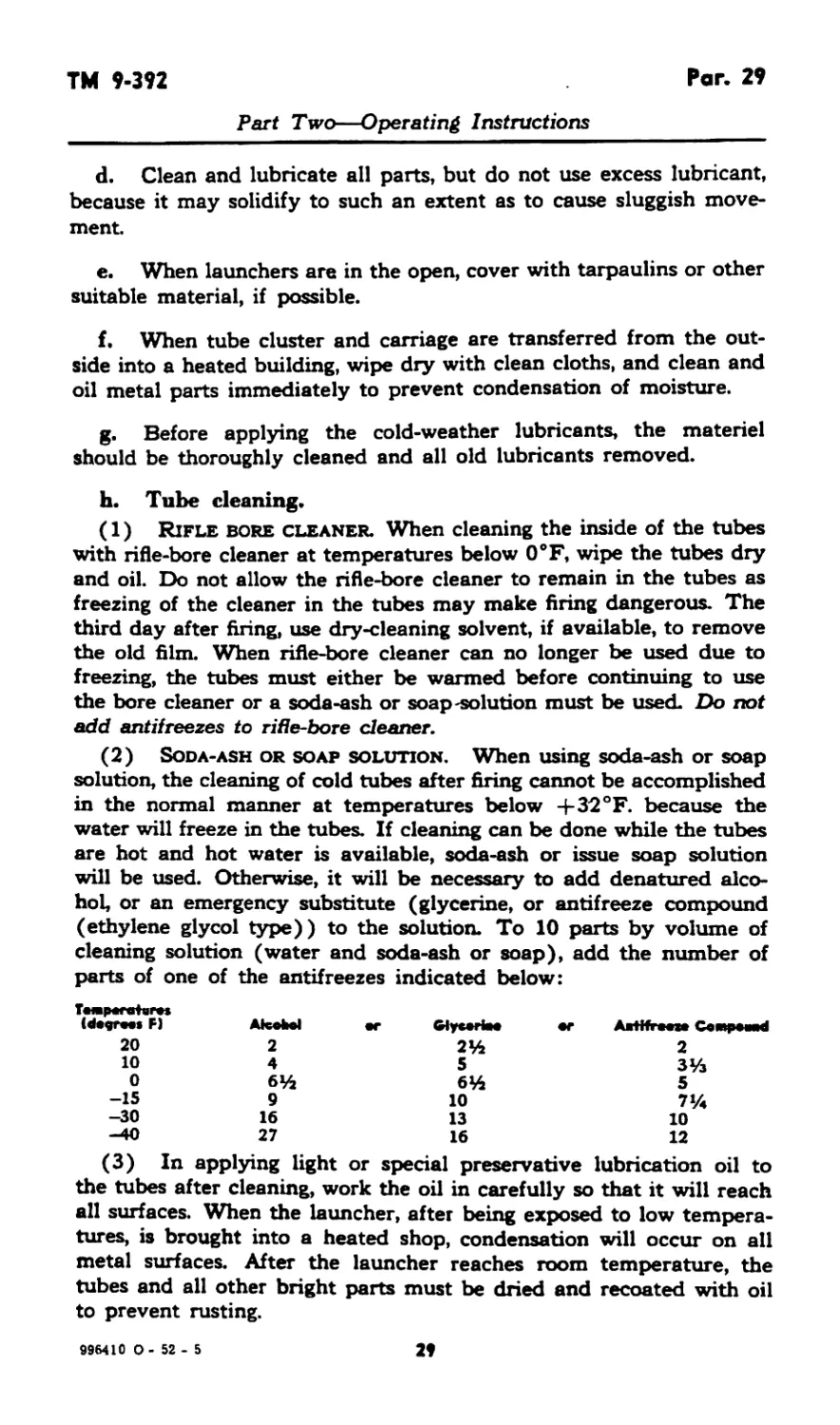
(2) Soda-ash or soap solution. When using soda-ash or soap
solution, the cleaning of cold tubes after firing cannot be accomplished
in the normal manner at temperatures below +32 °F. because the
water will freeze in the tubes. If cleaning can be done while the tubes
are hot and hot water is available, soda-ash or issue soap solution
will be used. Otherwise, it will be necessary to add denatured alco-
hol, or an emergency substitute (glycerine, or antifreeze compound
(ethylene glycol type)) to the solution. To 10 parts by volume of
cleaning solution (water and soda-ash or soap), add the number of
parts of one of the antifreezes indicated below:
ТмрегоНг*»
F) Atafcl •r ШумНм •r Afferent СотрмИ
20 2 2% 2
10 4 5 ЗУз
0 6% 6% 5
-15 9 10 7%
-30 16 13 10
-40 27 16 12
(3) In applying light or special preservative lubrication oil to
the tubes after cleaning, work the oil in carefully so that it will reach
all surfaces. When the launcher, after being exposed to low tempera-
tures, is brought into a heated shop, condensation will occur on all
metal surfaces. After the launcher reaches room temperature, the
tubes and all other bright parts must be dried and recoated with oil
to prevent rusting.
996410 0 - 52 - 5 29
Pars. 29-31
TM 9-392
Part Two—Operating Instructions
(4) After firing, the tubes will be cleaned with bore cleaning
solution on 3 consecutive days thereafter, or longer if sweating con-
tinues, then dried, and oiled.
(5) During periods when the materiel is not fired, the oil film
will be renewed daily by swabbing with burlap saturated with oil.
Every 5 days, swab with dry-cleaning solvent, dry, and renew the oil
film.
30. HOT CLIMATE WITHIN TEMPERATURE RANGES.
a. In hot climates, inspect and clean the launcher as frequently
as required, rather than at fixed intervals.
b. Where humidity is high, clean and oil as soon as possible after
firing, when the launcher gets wet or dirty, or if there is any reason
to expect corrosion to start.
c. In temperatures above 90 eF, summer grade greases and oils
should be used as lubricants.
Section X
DEMOLITION TO PREVENT ENEMY USE
31. GENERAL.
a. The destruction of the materiel when subject to capture or
abandonment in the combat zone will be undertaken by the using
arm, only on authority delegated by the division or higher commander
as a command function when such action is deemed necessary as a
final resort to keep the materiel from reaching enemy hands.
b. Adequate destruction of artillery materiel means damaging
it in such a way that the enemy cannot restore it to usable condition
in the combat zone either by repair or by cannibalization. Adequate
destruction requires that:
(1) Enough parts essential to the operation of the materiel must
be damaged.
(2) Parts must be damaged beyond repair in the combat zone.
(3) The same parts must be destroyed on all materiel, so that
the enemy cannot make up one operating unit by assembling parts
from several partly destroyed units.
c. The tubes are the most vital parts of these weapons. These
are the first things to damage.
30
ТМ 9*392
Par*. 32-33
Part Two—Operating Instructions
32. DEMOLITION OF LAUNCHERS T66 AND T66E2.
a. Detach the sight If evacuation is possible, carry the sight If
not, smash the sight thoroughly.
b. Insert one incendiary grenade M14 midway in the center tube
at zero-degree elevation. Ignite this grenade by inserting one other
grenade, equipped with a 15-second safety fuze. Take cover, as the
danger zone is at least 100 yards.
33. DEMOLITION OF AMMUNITION. Demolition of ammuni-
tion is covered in TM 9-1901.
31
Pars. 34-36
TM 9-392
PART THREE—MAINTENANCE INSTRUCTIONS
Section XI
GENERAL
34. SCOPE. Part Three contains information for the guidance
of the personnel of the using organizations responsible for the main-
tenance (first- and second-echelon) of this equipment It contains
information needed for the performance of the scheduled lubrication
and preventive maintenance services as well, as a description of the
major systems and units and their functions in relation to other com-
ponents of the equipment.
35. CLEANING AND PRESERVING MATERIALS. The follow-
ing cleaners and preservatives are issued for use with this materiel
(see SNL K-l and TM 9-850 for detailed information):
BURLAP, jute
CLEANER, rifle-bore
CLOTH, crocus
CLOTH, wiping, cotton
GREASE, O.D.
OIL, engine
OIL, preservative lubricating (special)
SODA-ASH
SOLVENT, dry-cleaning
Section XII
LUBRICATION
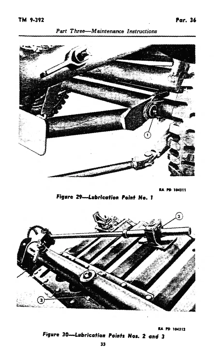
36. LUBRICATION ORDER.
a. Reproduction of War Department Lubrication Order LO 9-392
(fig. 28) prescribes first- and second-echelon lubrication maintenanca-
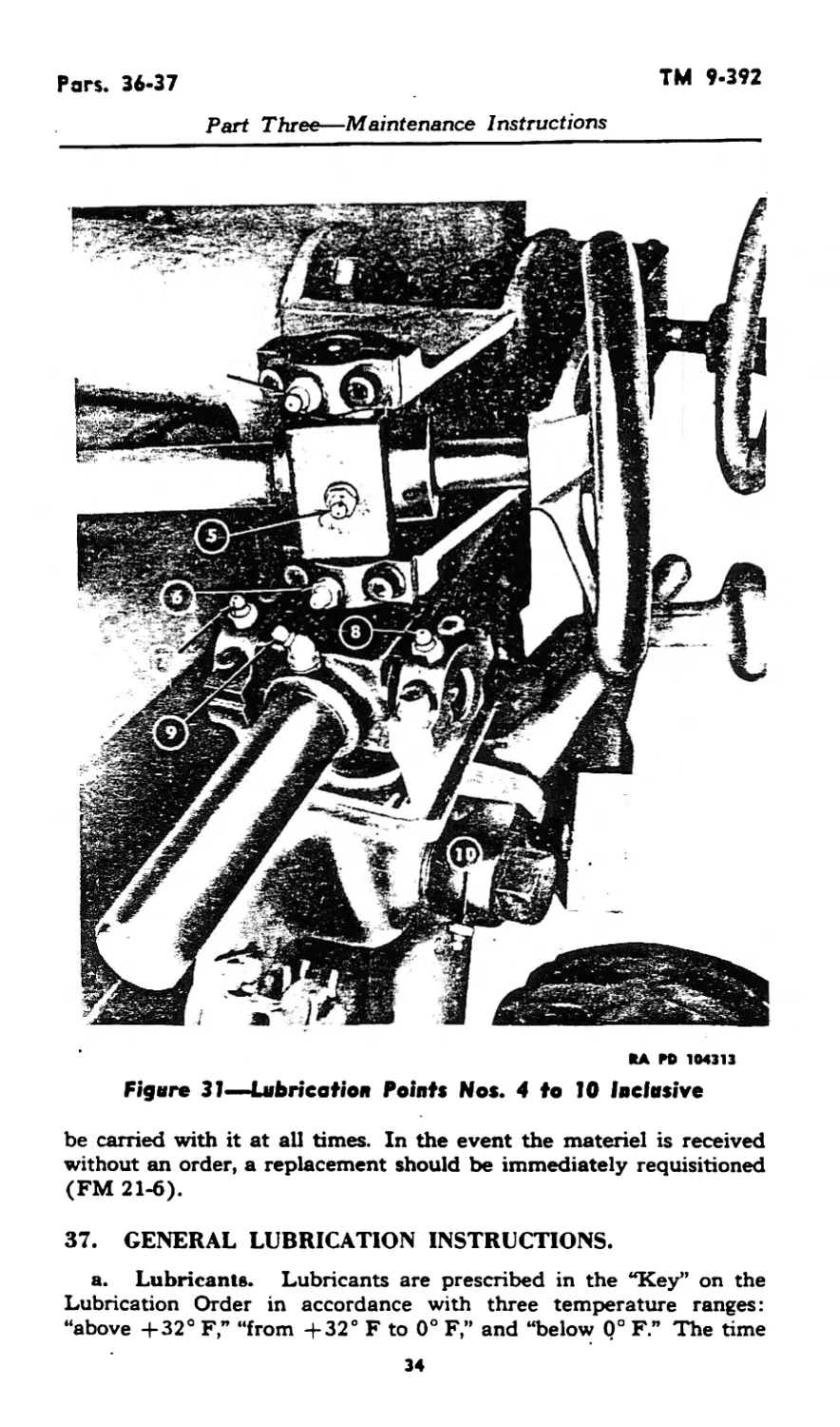
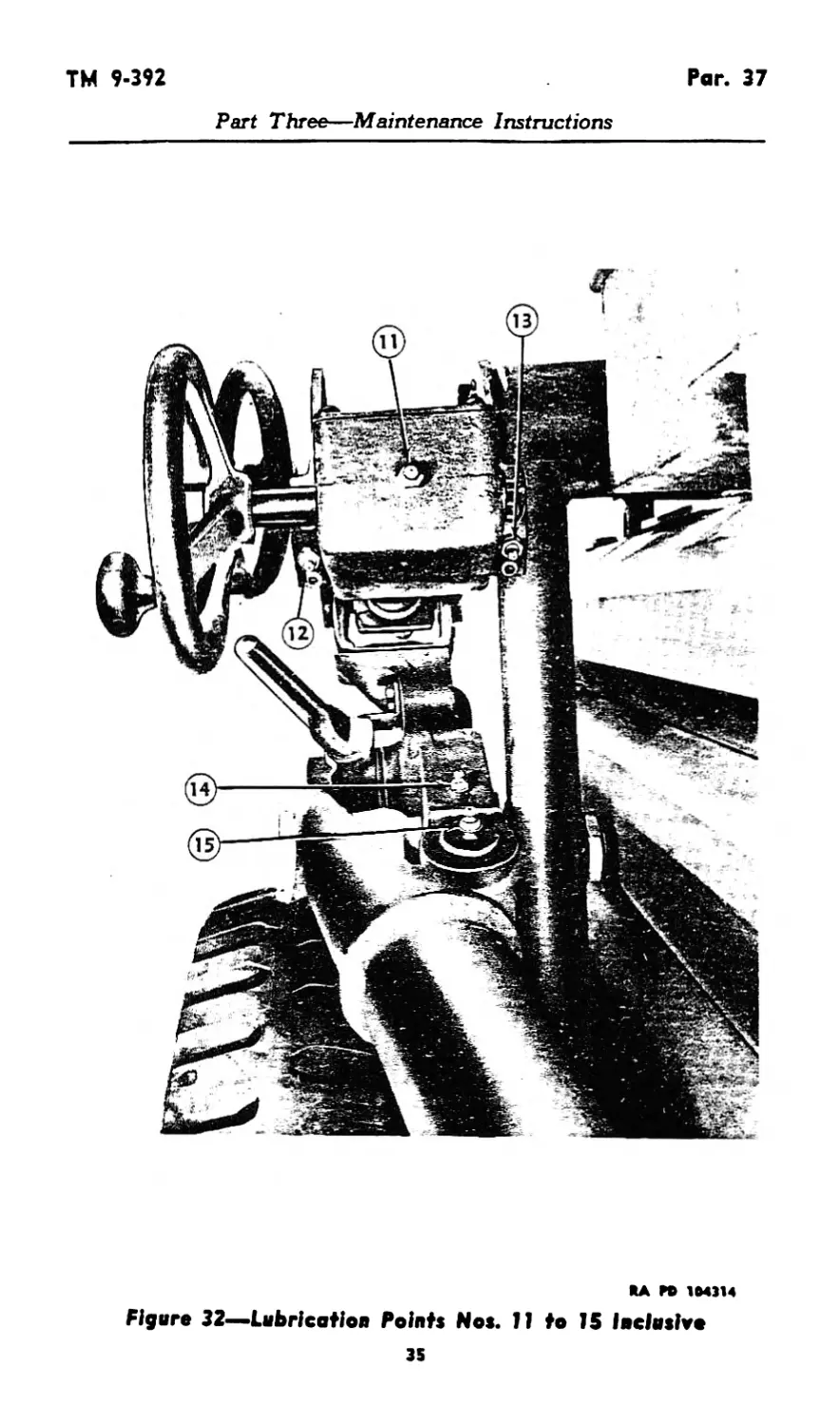
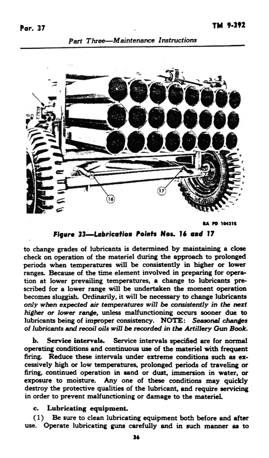
b. The lubricating fittings indicated on the order are illustrated
in figures 29 to 33, showing their location on the materiel. The
fittings shown in the figures may be identified on the order by the
key numbers around the border.
c. A lubrication order (formerly War Department Lubrication
Guide) is placed on or is issued with each item of materiel and is to
Figure 28—War Department Lubrication Order LO 9-392
(to be inserted when available I
32
ТМ 9.392
Par. 36
Part Three—Maintenance Instructions
RA M> 1МЛ1
Figure 29—Lubrication Point He. 1
RA ГО 1C4312
Figure 30—.Lubrication Points No*. 2 and 3
33
Pars. 36-37
TM 9-392
Part Three—Maintenance Instructions
RA ГО 104313
Figure 31—Lubrication Points Nos. 4 to 10 Inclusive
be carried with it at all times. In the event the materiel is received
without an order, a replacement should be immediately requisitioned
(FM 21-6).
37. GENERAL LUBRICATION INSTRUCTIONS.
a. Lubricants. Lubricants are prescribed in the “Key” on the
Lubrication Order in accordance with three temperature ranges:
“above +32° F,” “from +32° F to 0° F,” and “below 0° F.” The time
34
TM 9-392
Par. 37
Part Three—Maintenance Instructions
RA P0 1M314
Figure 32—Lubrication Points Nos. 11 to IS Inclusive
35
Par. 37
TM 9-392
Part Three—Maintenance Instructions
RA PO 10431*
Figure 33—Lubrication Points Nos. 16 and 17
to change grades of lubricants is determined by maintaining a close
check on operation of the materiel during the approach to prolonged
periods when temperatures will be consistently in higher or lower
ranges. Because of the time element involved in preparing for opera-
tion at lower prevailing temperatures, a change to lubricants pre-
scribed for a lower range will be undertaken the moment operation
becomes sluggish. Ordinarily, it will be necessary to change lubricants
only when expected air temperatures will be consistently in the next
higher or lower range, unless malfunctioning occurs sooner due to
lubricants being of improper consistency. NOTE: Seasonal changes
of lubricants and recoil oils will be recorded in the Artillery Gun Book.
b. Service intervals. Service intervals specified are for normal
operating conditions and continuous use of the materiel with frequent
firing. Reduce these intervals under extreme conditions such as ex-
cessively high or low temperatures, prolonged periods of traveling or
firing, continued operation in sand or dust, immersion in water, or
exposure to moisture. Any one of these conditions may quickly
destroy the protective qualities of the lubricant, and require servicing
in order to prevent malfunctioning or damage to the materiel
c. Lubricating equipment.
(1) Be sure to clean lubricating equipment both before and after
use. Operate lubricating guns carefully and in such manner as to
3»
ТМ 9-392
Par. 37
Part Three—Maintenance Instructions
insure proper distribution of the lubricant. If lubrication fitting valves
stick and prevent the entrance of lubricant, remove the fitting and
determine cause. Replace broken or damaged lubricators. If lubri-
cator cannot be replaced immediately, cover hole with tape as a
temporary expedient to prevent the entrance of dirt. If oil lines become
clogged, disassemble the line and remove the obstruction.
(2) Lubrication fittings, grease cups, oilers, oil holes, and plugs
are circled in red for ready identification.
(3) Wipe lubricators and surrounding surfaces clean before ap-
plying lubricant Where relief valves are provided, apply new
lubricant until the old lubricant is forced from the vent Exceptions
are specified in notes or on the Lubrication Order. Metal surfaces
on which a film of lubricant must be maintained by manual applica-
tion, will always be wiped clean before the film is renewed.
d. Gleaning.
(1) Unless otherwise specified, use rifle-bore cleaner or dry-
cleaning solvent to clean or wash all metal parts, whenever partial or
total disassembly is undertaken, or when renewing the protective
lubricant film on exposed metal surfaces. Flushing of gear cases
and bearing housings will not be undertaken unless inclosed mecha-
nism is first disassembled in order to insure complete removal of the
cleaner or solvent prior to the application of lubricants. Use of gaso-
line for cleaning is prohibited. Dry all parts thoroughly before
lubricating.
(2) Care must be taken when cleaning oil and grease compart-
ments to insure the complete removal of all residue or sediment.
Dirt or other foreign matter should not be allowed to drop into any of
the lubricating compartments.
e. Lubrication.
(1) Fill elevating and traversing mechanisms with OJD. grease
No. 0 above 4-32° F or No. 00 below 4-32° F, monthly.
(2) The wheel bearings should be removed at б-month intervals
for lubrication with general purpose grease No. 2.
(3) Lubricate other bearings equipped with lubrication fittings
with O.D. grease No. 0 above 4-32° F or No. 00 below 4-32° F,
monthly.
(4) Clean all unpainted metal surfaces, latches, and linkages of
the carriage daily, and oil with engine oil SAE 30 above 4-32° F or
SAE 10 between 32° F and 0° F, or preservative lubricating oil
(special) below 0° F.
996410 O* 52 • 6 37
Pars. 38-39
TM 9-392
Part Three—Maintenance Instructions
Section XIII
PREVENTIVE MAINTENANCE SERVICE
38. GENERAL.
a. Scope. Preventive maintenance services prescribed by Army
Regulations are a function of using-organization echelons of main-
tenance. This section contains preventive maintenance service allo-
cated to crew and scheduled preventive maintenance service allocated
to (second echelon) organizational maintenance.
b. Cleanliness. Dirt or grit, accumulated in traveling or from
blast of piece in firing, settles on bearing surfaces and forms a cutting
compound. Powder fouling attracts moisture and settles in operating
grooves, preventing proper operation of moving parts, and hastens
the formation of rust. It is essential that all parts be cleaned at fre-
quent intervals, depending upon use and service.
c. Rust removal. If rust should accumulate, its removal from
bearing surfaces requires special care in order that clearance shall
not be unduly increased. Crocus cloth should be used for this purpose.
The use of coarse abrasives is strictly forbidden.
d. Care. When materiel is not in use, suitable tarpaulins should
be used as covers. When materiel is not to be used for considerable
time, all bright unpainted metal surfaces should be cleaned with dry-
cleaning solvent and coated with rust-preventive compound.
39. PREVENTIVE MAINTENANCE SCHEDULES.
a. Tube Before firing. Point cluster Preveettv* MeinteiHiKce Clean and dry. Detailed lestrectioei Par. 42 a
h. After firing. Tube cluster Firing cable Clean Clean. and oil. Par. Par. 37 42 d e
c. Tube Daily service, cluster Clean and oil. Par. 42 c
d. If used in wet Contact fingers and exposed wires weather. Dry. Par. 42 d
38
ТМ 9-392
Par. 40
Part Three—Maintenance Instructions
Section XIV
MALFUNCTIONS AND CORRECTIONS
40. FAILURE TO FIRE.
a. Contacts may become rusted or corroded. Clean them with
crocus cloth.
b. Live contact is insulated from tube by air space. Should
these contacts be damaged so that they touch the tube, contact will
be shorted and rocket will not fire. The contacts may be adjusted by
bending them slightly up or down. Contact may be replaced com-
pletely using the wrench provided.
c. If couplings on firing cable are damaged or broken, a temporary
repair may be made until the ordnance maintenance personnel are
notified.
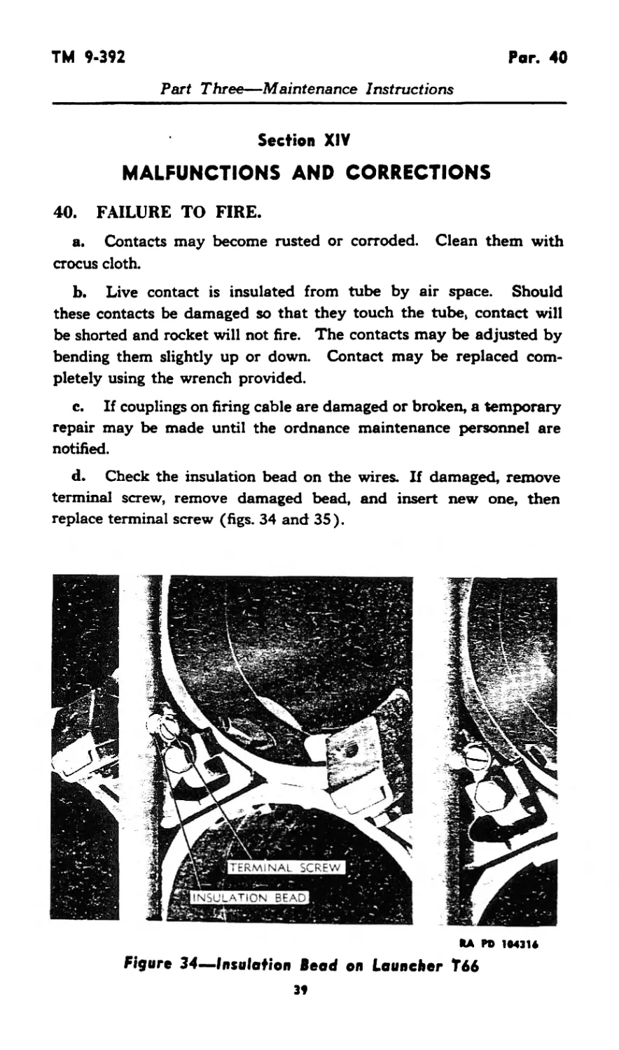
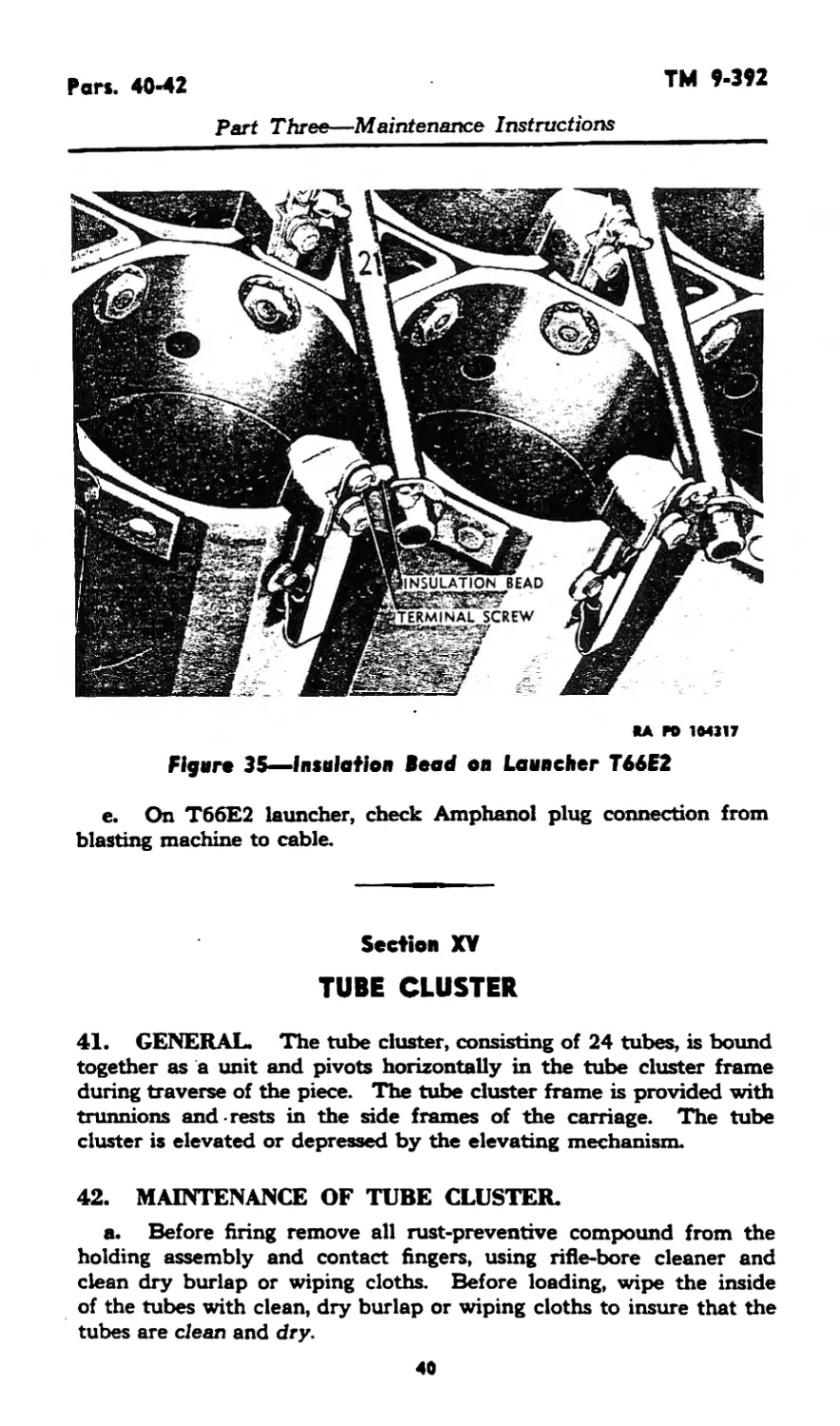
d. Check the insulation bead on the wires. If damaged, remove
terminal screw, remove damaged bead, and insert new one, then
replace terminal screw (figs. 34 and 35).
KA PD 1M3U
Figure 34—Insulation Bead on Launcher T66
Pars. 40-42
TM 9-392
Part Three—Maintenance Instructions
*A PO 104117
Figure 35—Insulation Bead on Launcher T66E2
e. On T66E2 launcher, check Amphanol plug connection from
blasting machine to cable.
Section XV
TUBE CLUSTER
41. GENERAL. The tube cluster, consisting of 24 tubes, is bound
together as a unit and pivots horizontally in the tube cluster frame
during traverse of the piece. The tube cluster frame is provided with
trunnions and-rests in the side frames of the carriage. The tube
cluster is elevated or depressed by the elevating mechanism.
42. MAINTENANCE OF TUBE CLUSTER.
a. Before firing remove all rust-preventive compound from the
holding assembly and contact fingers, using rifle-bore cleaner and
clean dry burlap or wiping cloths. Before loading, wipe the inside
of the tubes with clean, dry burlap or wiping cloths to insure that the
tubes are clean and dry.
40
TM 9-392
Par. 42
Part Three—Maintenance Instructions
b. After firing, clean and oil the inside of the tubes as prescribed
in paragraph 37 d.
c. When not being fired, wipe tubes clean daily and renew the oil
film. To remove gummy deposits of congealed oil, swab with dry-
cleaning solvent, wipe thoroughly dry, and reoil. A cleaning staff
is issued with the launcher.
d. If the launcher has been used in wet weather, dry all electric
contact points and exposed wires with a dry cloth. Clean and oil the
rest of the launcher as described above.
e. After firing, wipe the firing cable clean of any dirt, grease, or
foreign material, using clean, dry burlap or wiping cloths.
f. Bore cleaning and preservation. The following materials
and cleaning and preserving procedures will be used for the inside
of the tubes in order of indicated preference. Oils to be applied after
cleaning will be the same as prescribed by applicable War Depart-
ment Lubrication Orders and Technical Manuals for specific tem-
perature ranges.
(1) Rifle-bore cleaner.
(a) After firing, and on two consecutive days thereafter, thor-
oughly clean the inside of the tubes with rifle-bore cleaner making sure
that all surfaces are well coated. Do not wipe dry.
(b) On the third day after firing, clean the inside of the tubes
with rifle-bore cleaner. If the piece will probably be fired within the
next 24 hours, do not wipe dry. If the piece will not be fired within the
next 24 hours, wipe dry and coat with the prescribed oil.
(c) After the third day since firing, renew the oil film daily.
Every fifth day, clean with rifle-bore cleaner, wipe dry, and reoil.
(2) Soda-ash.
(a) Prepare a solution of one-half pound soda-ash to each gallon
of warm water. In temperatures below 4-32° F, add the type and
amount of antifreeze prescribed in TM 9-850, if the tubes to be cleaned
are cold.
(b) Immediately after firing and on three consecutive days there-
after, thoroughly clean the tubes with the soda-ash solution. Rinse
with clean warm water and wipe dry. Coat with the prescribed oil.
(c) When the piece is not being fired, renew the oil film daily.
Every fifth day, clean the tubes with dry-cleaning solvent or rifle-bore
cleaner, if available. Wipe dry and reoil.
(3) Soap.
(a) Use castile soap or issue soap.
(b) Prepare a sponging solution by shaving one pound of soap
into four gallons of water. If possible, warm the water to facilitate
dissolving the soap. In temperatures below +32° F, add the type
41
Pars. 42-43
TM 9-392
Part Three—Maintenance Instructions
and amount of antifreeze prescribed in TM 9-850, if the tube to be
cleaned is cold.
(c) Follow the same cleaning, drying, and oiling procedure pre-
scribed for the soda-ash solution.
CAUTION: When issue soap is used, the tubes must be thoroughly
rinsed after cleaning as the soap may contain free caustic which will
cause corrosion if it is not completely removed.
(4) Hot water.
(a) As a temporary measure after firing, the tubes may be cleaned
while still hot by swabbing with quantities of hot water. This method
will be used only when rifie-bore cleaner, soda-ash, or soap are not
available. Extreme care must be taken to thoroughly dry the tubes
after cleaning with hot water. A coating of oil will be applied imme-
diately thereafter, to prevent rusting.
(b) Swabbing with hot water may not remove all of the primer
salts or powder residue. It is most important, therefore, that the tubes
be cleaned as soon as possible in accordance with paragraph 37 a,
b, or c.
Section XVI
FIRING MECHANISM
43. GENERAL.
a. The firing mechanism is a ten-cap blasting machine (fig. 9).
It is used as a source of electricity for firing the rocket from the
launchers Тбб and T66E2.
b. This machine is a small portable dynamo or magneto which
weighs about five pounds. Two terminals are located on the upper
surface of the body of the exploder. The exploder is operated by
twisting the handle. The quicker the twist, the more current gener-
ated. The firing handle of this machine is removable. It should be
detached from the machine until the rockets are ready to be fired.
c. The exploder can be connected to the firing box by the de-
tachable firing cable which leads to the firing box (on the T66E2
launcher, the Amphanol plug connection is made) (fig. 20). Prior
42
ТМ 9-392
Pars. 43-45
Part Three—Maintenance Instructions
oooooooo
00000000
00000000
RA PD 104274
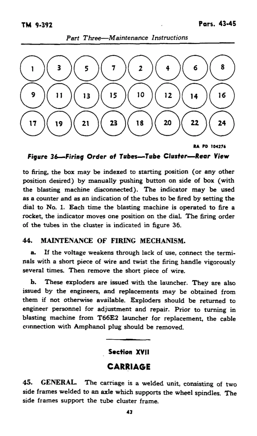
Figure 36—Firing Order of Tubes—Tube Cluster—Rear View
to firing, the box may be indexed to starting position (or any other
position desired) by manually pushing button on side of box (with
the blasting machine disconnected). The indicator may be used
as a counter and as an indication of the tubes to be fired by setting the
dial to No. 1. Each time the blasting machine is operated to fire a
rocket, the indicator moves one position on the dial. The firing order
of the tubes in the cluster is indicated in figure 36.
44. MAINTENANCE OF FIRING MECHANISM.
a. If the voltage weakens through lack of use, connect the termi-
nals with a short piece of wire and twist the firing handle vigorously
several times. Then remove the short piece of wire.
b. These exploders are issued with the launcher. They are also
issued by the engineers, and replacements may be obtained from
them if not otherwise available. Exploders should be returned to
engineer personnel for adjustment and repair. Prior to turning in
blasting machine from T66E2 launcher for replacement, the cable
connection with Amphanol plug should be removed.
Section XVII
CARRIAGE
45. GENERAL. The carriage is a welded unit, consisting of two
side frames welded to an axle which supports the wheel spindles. The
side frames support the tube cluster frame.
43
Pars. 46-49
TM 9-392
Part Three—Maintenance Instructions
46. MAINTENANCE OF CARRIAGE. Maintenance of the car-
riage consists of lubricating latches and linkages, and lubricating all
points equipped with lubricating fittings (see section XII).
Section XVIII
TRAILS AND TIE RODS
47. GENERAL. The trails of the T66 launcher are welded as-
semblies which consist of the trail body, spades, and lunette. The
trails of the T66E2 launcher are welded assemblies consisting of the
trail body and spades. A detachable lunette is provided at the spade
end of the trails. The trails of both launchers are hinged to the car-
riage side frames. Trail locks are located on the sides of the carriage.
A trail traveling lock is provided on the back end of the trails. Tie
rods, which are provided to support the trails, are fastened to the
middle portion of the trails and to brackets on the axle of the carriage
(fig. 3).
43. MAINTENANCE OF THE TRAILS AND TIE RODS.
a. If the lunette on the T66E2 launcher is damaged, it may be
replaced.
b. The tie rods are to be kept tight by means of the turnbuckles,
should they become loose. Looseness of the tie rods adversely affects
stability of the launchers when fired at maximum traverse.
Section XIX
CONTROL BOX
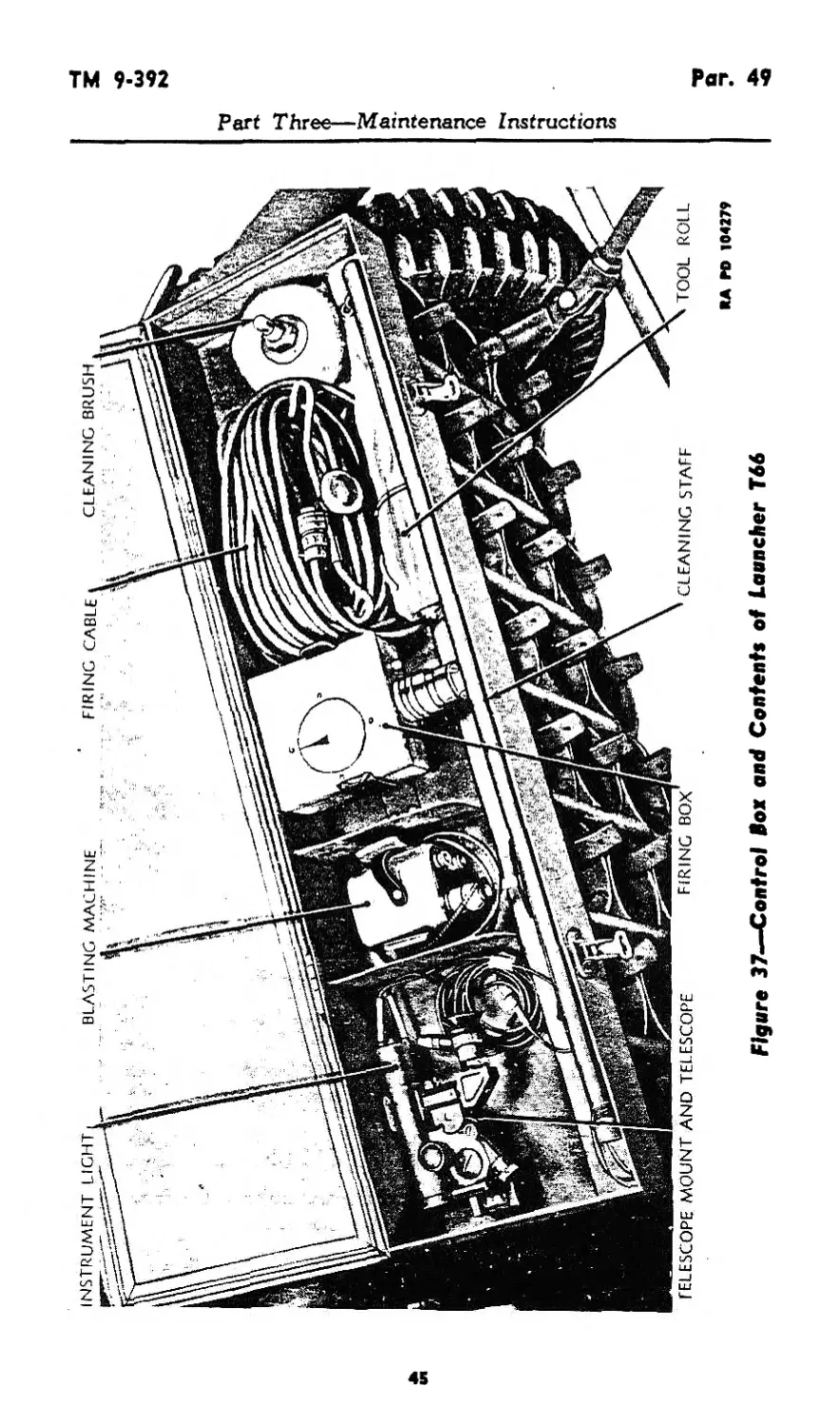
49. GENERAL. The control box on both launchers is fastened on
the rear portion of the tube cluster (figs. 1 and 2). The box on the
T66 launcher contains the ten-cap blasting machine, firing handle,
firing box, firing cable, telescope mount with elbow telescope, instru-
ment light, cleaning brush and staff, tool kit, and spare parts (fig. 37).
44
Figure 37—Control Box and Contents of Launcher T66
RA PO 104279
и
*
<*♦>
Pars. 49-51
TM 9-392
Part Three—Maintenance Instructions
KA PO 1043»
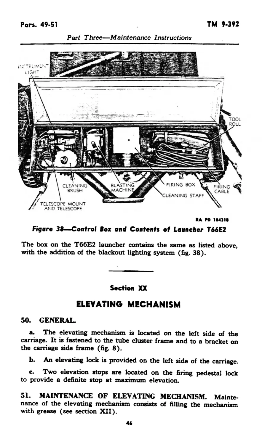
Figure 38—Control Box and Contents of Launcher T66E2
The box on the T66E2 launcher contains the same as listed above,
with the addition of the blackout lighting system (fig. 38).
Section XX
ELEVATING MECHANISM
SO. GENERAL.
a. The elevating mechanism is located on the left side of the
carriage. It is fastened to the tube cluster frame and to a bracket on
the carriage side frame (fig. 8).
b. An elevating lock is provided on the left side of the carriage.
c. Two elevation stops are located on the firing pedestal lock
to provide a definite stop at maximum elevation.
51. MAINTENANCE OF ELEVATING MECHANISM. Mainte-
nance of the elevating mechanism consists of filling the mechanism
with grease (see section XII).
46
TM 9-392
Pars. 52-56
Part Three—Maintenance Instructions
Section XXI
TRAVERSING MECHANISM
52. GENERAL.
a. The traversing mechanism is located on the left side of the
carriage. It is fastened to the tube cluster frame and tube cluster
unit (fig. 8).
b. A traversing lock is provided on top of the tube cluster frame.
53. MAINTENANCE OF THE TRAVERSING MECHANISM.
Maintenance of the traversing mechanism consists of filling the
mechanism with grease (see section XII).
Section XXII
FIRING PEDESTAL
54. GENERAL. The firing pedestal is a welded assembly. The
pedestal is dropped to the ground for firing position and is locked
in place (fig. 5). The pedestal is held in traveling position by locking
bars.
Section ХХШ
SIGHT BRACKET
55. GENERAL. The sight bracket is bolted to the front left corner
of the tube cluster (fig. 8). A cross-leveling screw is located to the
right of the bracket for use in maintaining the telescope mount
vertical.
Section XXIV
WHEELS
56. GENERAL. The wheels are of commercial type and mount a
6.00 x 16 tire. These wheels are directly interchangeable with those
used on jeeps.
47
Рог. 57
TM 9-392
Part Three—Maintenance Instructions
57. MAINTENANCE OF WHEELS.
a. There is no provision for adjustment of camber, caster, or
toe-in on the axle.
b. Pack the wheel bearings with grease, as prescribed on the
Lubrication Order (fig. 28).
c. Special attention should be given to keeping the wheel stud
nuts tight
41
TM 9-392
Pars. 58-59
PART FOUR—AUXILIARY EQUIPMENT
Sectioa XXV
GENERAL
58. SCOPE. Part Four contains information for the guidance of
the personnel responsible for the operation of this equipment. It con-
tains only the information necessary to using personnel to properly
identify, connect, and protect such auxiliary equipment while being
used or transported with the main equipment. Detailed instructions
pertaining to auxiliary equipment are contained in pertinent Tech-
nical Manuals.
Section XXVI
AMMUNITION
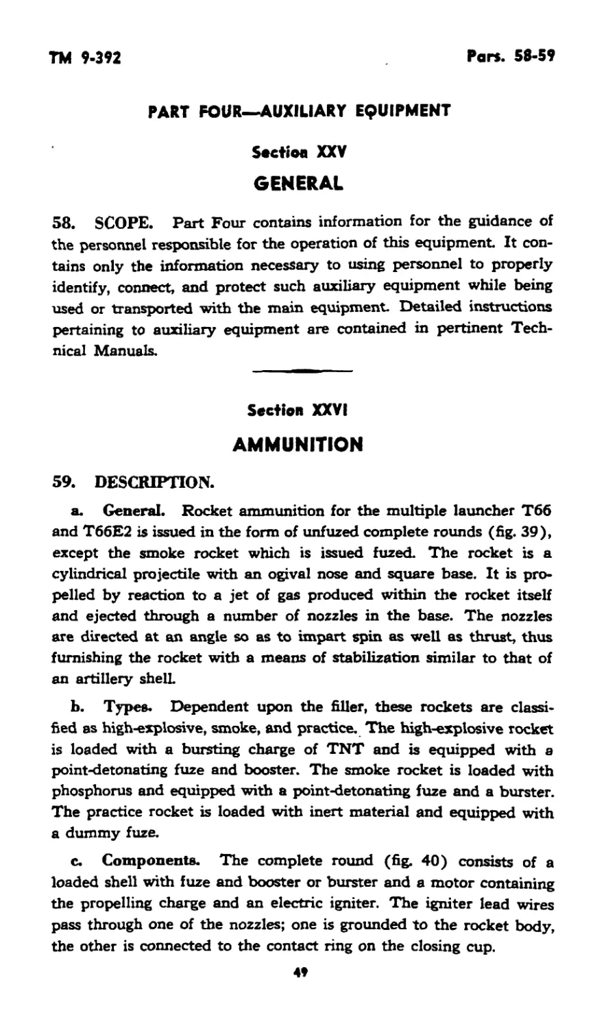
59. DESCRIPTION.
a. General. Rocket ammunition for the multiple launcher Тбб
and T66E2 is issued in the form of unfuzed complete rounds (fig. 39),
except the smoke rocket which is issued fuzed. The rocket is a
cylindrical projectile with an ogival nose and square base. It is pro-
pelled by reaction to a jet of gas produced within the rocket itself
and ejected through a number of nozzles in the base. The nozzles
are directed at an angle so as to impart spin as well as thrust, thus
furnishing the rocket with a means of stabilization similar to that of
an artillery shell
b. Types. Dependent upon the filler, these rockets are classi-
fied as high-explosive, smoke, and practice. The high-explosive rocket
is loaded with a bursting charge of TNT and is equipped with a
point-detonating fuze and booster. The smoke rocket is loaded with
phosphorus and equipped with a point-detonating fuze and a burster.
The practice rocket is loaded with inert material and equipped with
a dummy fuze.
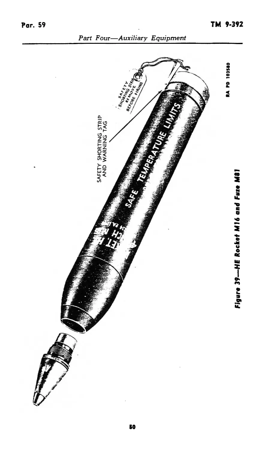
c. Components. The complete round (fig. 40) consists of a
loaded shell with fuze and booster or burster and a motor containing
the propelling charge and an electric igniter. The igniter lead wires
pass through one of the nozzles; one is grounded to the rocket body,
the other is connected to the contact ring on the closing cup.
4»
-v
Q
Figure 39—HE Rocket MH and Fate M81
RA RD 1035*0
Part Four—Auxiliary Equipment
СЛ
*o
*O
<A>
K>
Figure 40—Unfuxed Rocket—Sectional View
Part Four—Auxiliary Equipment
Pers. 60-61
TM 9-392
Part Four—Auxiliary Equipment
60. IDENTIFICATION.
a. General. In common with other types of ammunition, rockets
are identified by means of the painting and marking on the item and
its packings. Positive identification consists of the standard nomencla-
ture of the item and its ammunition lot number.
b. Painting. Ammunition is painted to prevent rust and to pro-
vide, by the color, a means of identification as to type..
(1) Rocket shell:
Higb-«xplosive....Olive drab, marking in yellow
Smoke ...........Gray, one band and marking all in yellow
Practice ........Blue, marking in white
(2) Rocket motors. Since motors for all types of rockets con-
tain full service charge, they are painted olive drab and marked in
yellow.
c. Marking. Marking stenciled on the rocket includes type,
caliber, model, lot number, loaders initials, date loaded, and safe
temperature limits.
d. Standard nomenclature. Standard nomenclature is estab-
lished in order that each item may be specifically identified by name.
It consists of the name, type, size, and model designation. The model
designation is assigned when the item is standardized; it consists of
the letter M and an arabic numeral. Modifications of the original de-
sign are designated by the addition of the letter A and the appropriate
numeral; for example, M6A3 indicates the third modification of an
item originally adopted as M6. When a modification is of a temporary
nature or does not supersede the basic eiodel, it is indicated by adding
a letter: M6A3D. Standard nomenclature of rockets is published in
ASF Catalog, ORD 11 SNL S-9.
e. Ammunition lot number. A lot of ammunition consists of a
number of items, manufactured under uniform conditions from uni-
form materials, which are expected to function uniformly. The lot
number identifies each individual lot of ammunition and is required
for all purposes of record making reference to particular items of
ammunition.
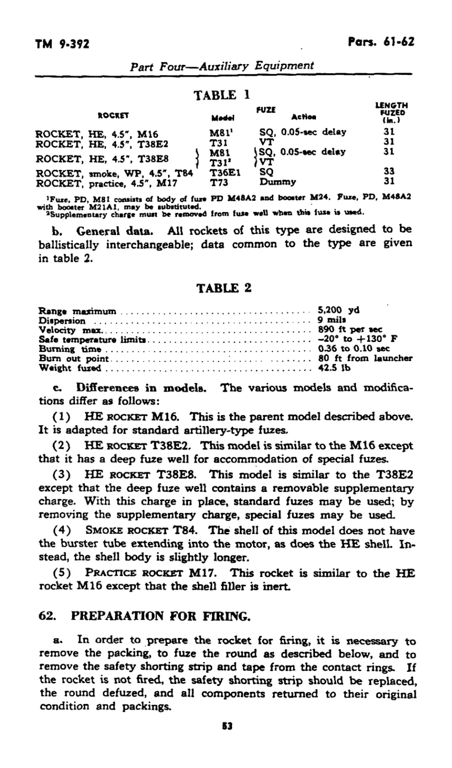
61. AUTHORIZED ROUNDS.
a. List of rounds. The rockets authorized for firing from these
launchers and specific data are listed in Table 1.
S2
TM 9-392
Pars. 61-62
Part Four—Auxiliary Equipment
ROCKET
ROCKET, HE, 4.5', M16
ROCKET, HE, 4.5", T38E2
ROCKET, HE, 4.5", T38E8
ROCKET, smoke, WP, 4.5", T84
ROCKET, practice, 43", M17
TABLE 1 LENGTH
MaM FUZE Aetioa fuzed (hi.)
M81* SQ, 0.05-sec delay 31
T31 VT 31
S M81 \SQ, 0.05-eec delay 31
} ТЗГ /VT
T36E1 SQ 33
T73 Dummy 31
’Fuxe, PD, M81 con»i«t« of body of fuxo PD M48A2 and booowr M24. Fuxe, PD, M48A2
with booster M21A1, may be substituted. .. . -. ‘, j
^Supplementary charge must be removed from fuse well when Vm fuse is uaed.
b. General data. All rockets of this type are designed to be
ballistically interchangeable; data common to the type are given
in table 2.
TABLE 2
Rang* maximum........................................
Dispersion ..........................................
Velocity max.........................................
Safe temperature limits..............................
Burning time.........................................
Bum out point........................ ...............
Weight fuzed.........................................
5,200 yd
9 mils
890 ft per sec
—20* to 4-130* F
036 to 0.10 sec
80 ft from launcher
42.5 lb
c. Differences in models. The various models and modifica-
tions differ as follows:
(1) HE rocket Ml6. This is the parent model described above.
It is adapted for standard artillery-type fuzes.
(2) HE rocket T38E2. This model is similar to the M16 except
that it has a deep fuze well for accommodation of special fuzes.
(3) HE rocket T38E8. This model is similar to the T38E2
except that the deep fuze well contains a removable supplementary
charge. With this charge in place, standard fuzes may be used; by
removing the supplementary charge, special fuzes may be used.
(4) Smoke rocket T84. The shell of this model does not have
the burster tube extending into the motor, as does the HE shell. In-
stead, the shell body is slightly longer.
(5) Practice rocket M17. This rocket is similar to the HE
rocket M16 except that the shell filler is inert.
62. PREPARATION FOR FIRING.
a. In order to prepare the rocket for firing, it is necessary to
remove the packing, to fuze the round as described below, and to
remove the safety shorting strip and tape from the contact rings. If
the rocket is not fired, the safety shorting strip should be replaced,
the round defuzed, and all components returned to their original
condition and packings.
53
Pars. 62-63
TM 9-392
Part Four—Auxiliary Equipment
b. Fuzing with standard fuzes.
(1) Remove rocket from packings and inspect to see that base
sealing disk is in place. If the disk is loose, it may be replaced and
the rocket used, provided it can be ascertained that no moisture or
other foreign material has entered the motor.
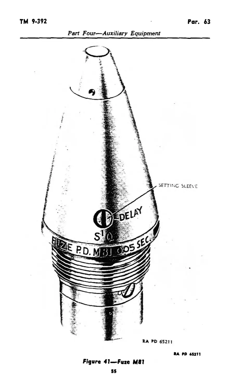
(2) Remove fuze from packings and inspect to insure there is no
corrosion and that there are no damaged threads. Set the fuze (fig. 41)
for desired action, superquick or delay, by turning the setting sleeve
across the axis of the fuze, or delay, or parallel to the fuze axis, for
superquick action.
(3) Loosen set screw in adapter and remove shipping plug.
Inspect fuze cavity for presence of foreign material and damaged
threads. When fuzing T38E8, be sure supplementary charge is present.
(4) Screw fuze into place and tighten with fuze wrench. Tighten
set screw in adapter.
c. Fuzing with VT fuzes. Fuzing the T38E2 or T38E8 with
special fuzes is essentially the same as the procedure for standard
fuzes described above except that the supplementary charge, when
present, must be removed. When special action is necessary, direc-
tions will be packed with the fuzes.
63. PRECAUTIONS IN HANDLING.
a. Rockets are packed to withstand conditions usually encoun-
tered in the field. However, since ammunition is adversely affected
by heat, shock, and moisture, due consideration should be given the
following:
(1) Packings should not be opened in advance of anticipated
needs and items prepared for firing but not used should be restored
to their original packings and resealed.
(2) Ammunition should be handled with care at all times. Pack-
ings should not be tumbled or dropped. Damaged packings should be
repaired or replaced with due care given to transferring all markings.
(3 ) Rockets and fuzes are particularly sensitive to heat and should
be protected against all sources of excessive heat, such as the direct
rays of the sun. If it is necessary to store such items in the open,
piles should be placed on dunnage and covered with paulins arranged
so that air can circulate freely through all parts of the stack.
b. Rockets must not be fired at temperatures outside the safe
temperatures marked on the rocket. Firing at temperatures below
those specified will result in erratic ranges; firing at temperatures above
the safe range will result in dangerous pressures being built up in the
rocket motor.
c. Rockets with dented bodies, damaged fuze threads, or missing
54
ТМ 9-392
Par. 63
Part Four—Auxiliary Equipment
*A RO 45211
Figure 41—Fuze M81
55
Par. 63
TM 9-392
Part Four—Auxiliary Equipment
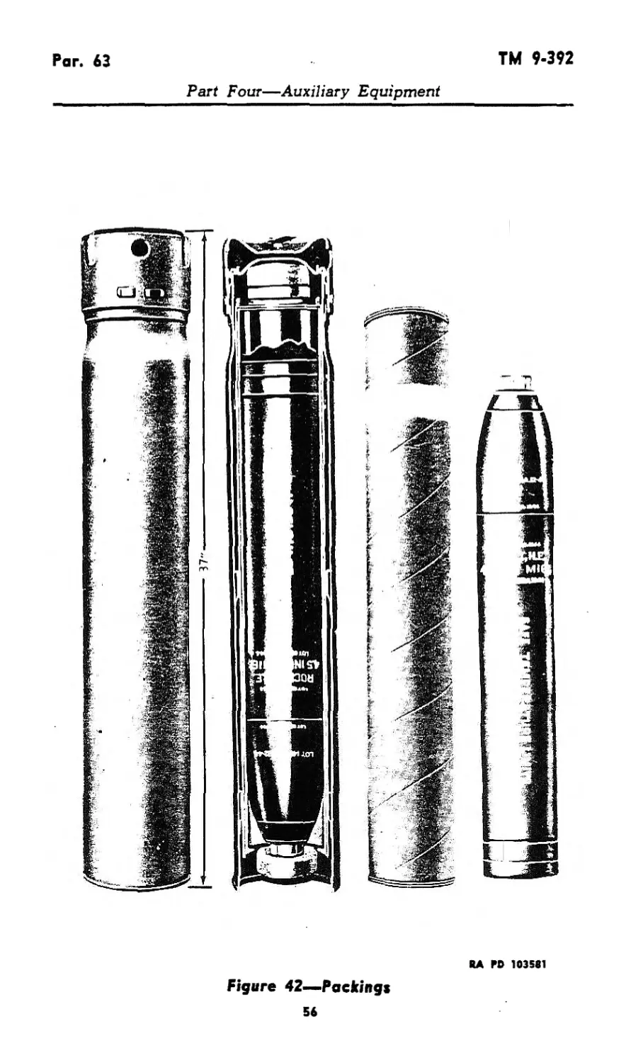
RA PO 103581
Figure 42—-Packing»
56
TM 9-392
Pars. 63-65
Part Four—Auxiliary Equipment
base closing disks should not be used. If the closing disk is loose, it
may be replaced, provided it can be ascertained that no moisture or
other foreign material has entered the motor.
d. Fuzes with damaged threads and those showing substantial
amounts of corrosion should not be used.
e. When a rocket is fired, the blast of flame extends to the rear
approximately 75 feet Personnel and materiel should be kept clear
of this area from the time the launcher is loaded until after the rocket
is fired. If practicable, inflammable material such as dry vegetation
should be cleared from this area before firing.
f. Care should be exercised to protect the rocket against stray
electric currents. If a rocket is accidentally ignited it takes off with
full service velocity. The safety shorting strip should be in place across
the contact rings at all times except when the rocket is in the launcher.
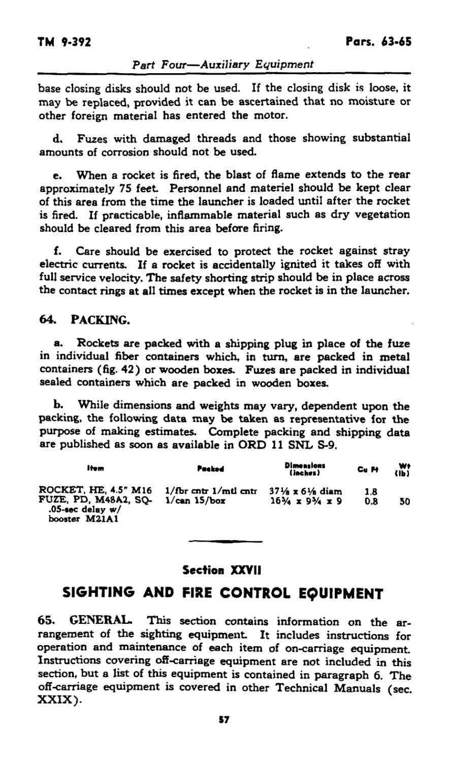
64. PACKING.
a. Rockets are packed with a shipping plug in place of the fuze
in individual fiber containers which, in turn, are packed in metal
containers (fig. 42) or wooden boxes. Fuzes are packed in individual
sealed containers which are packed in wooden boxes.
b. While dimensions and weights may vary, dependent upon the
packing, the following data may be taken as representative for the
purpose of making estimates. Complete packing and shipping data
are published as soon as available in ORD 11 SNL S-9.
Horn Peeked Dimensions (inches) Cu H Wf (lb)
ROCKET, HE, 4.5" M16 FUZE, PD, M48A2, SQ- .05-sec delay w/ booster M21A1 1/fbr cntr 1/mtl cntr 1/can 15 /box 37l/g x 6l/i diam 16% x 9Уч x 9 1.8 0.8 50
Section XXVII
SIGHTING AND FIRE CONTROL EQUIPMENT
65. GENERAL. This section contains information on the ar-
rangement of the sighting equipment. It includes instructions for
operation and maintenance of each item of on-carriage equipment.
Instructions covering off-carriage equipment are not included in this
section, but a list of this equipment is contained in paragraph 6. The
off-carriage equipment is covered in other Technical Manuals (sec.
XXIX).
57
Par. 66
TM 9-392
Part Four—Auxiliary Equipment
EYE SHIELD
HAND LIGHT
CLAMP SCREW
ELBOW TELESCOPE M62
'ilN OPERATING POSITION,
«SIGHT
BRACKEY
CROSS
.level
I NUT
TELESCOPE ADAPTER M9
TELESCOPE MOUNT T14SEI
RA ГО 102711
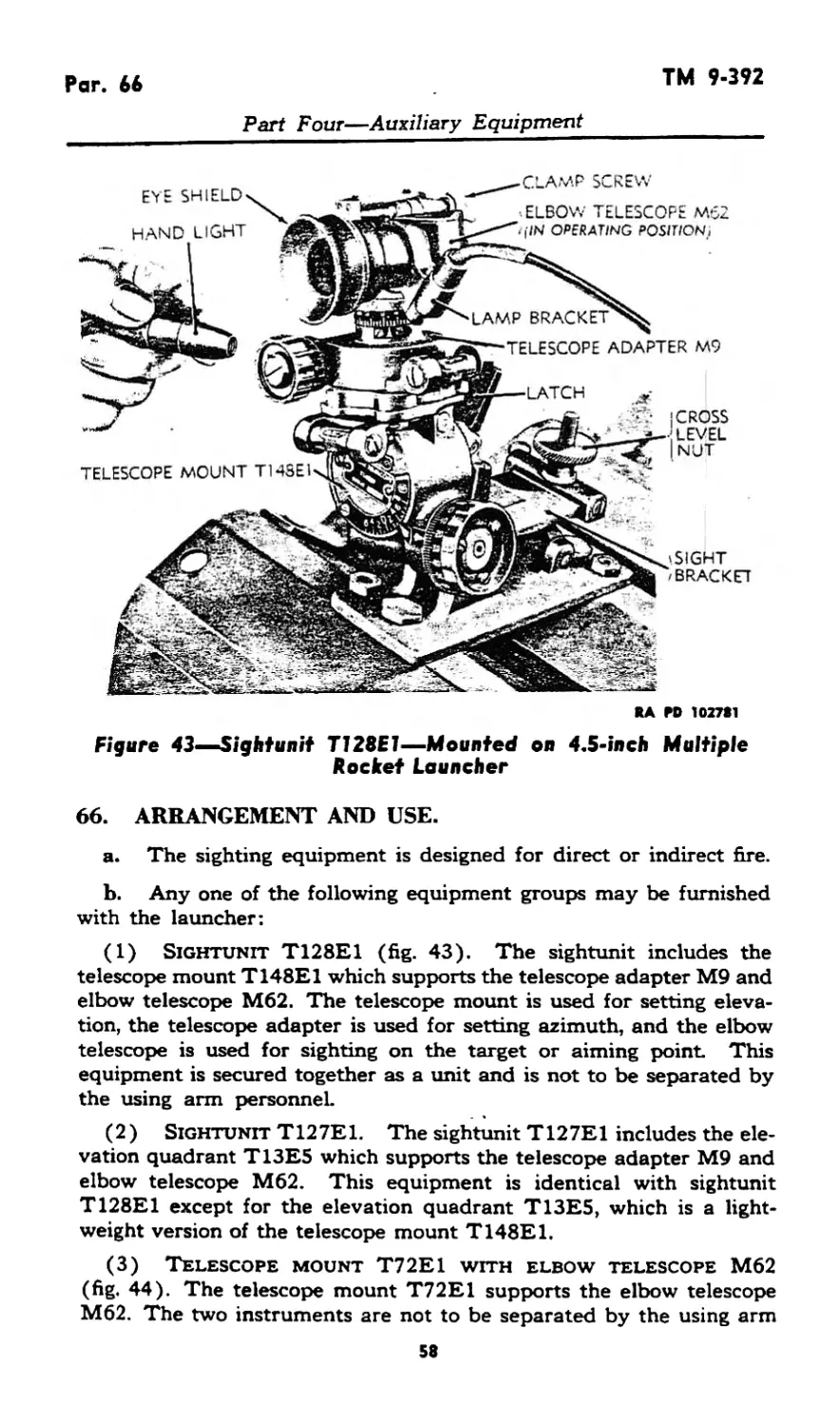
Figure 43«Sightunif T128E1—Mounted on 4.5-inch Multiple
Rocket Launcher
66. ARRANGEMENT AND USE.
a. The sighting equipment is designed for direct or indirect fire.
b. Any one of the following equipment groups may be furnished
with the launcher:
(1) Sightunit T128E1 (fig. 43). The sightunit includes the
telescope mount T148E1 which supports the telescope adapter M9 and
elbow telescope M62. The telescope mount is used for setting eleva-
tion, the telescope adapter is used for setting azimuth, and the elbow
telescope is used for sighting on the target or aiming point This
equipment is secured together as a unit and is not to be separated by
the using arm personnel.
(2 ) Sightunit T127E1. The sightunit T127E1 includes the ele-
vation quadrant T13E5 which supports the telescope adapter M9 and
elbow telescope M62. This equipment is identical with sightunit
T128E1 except for the elevation quadrant T13E5, which is a light-
weight version of the telescope mount T148E1.
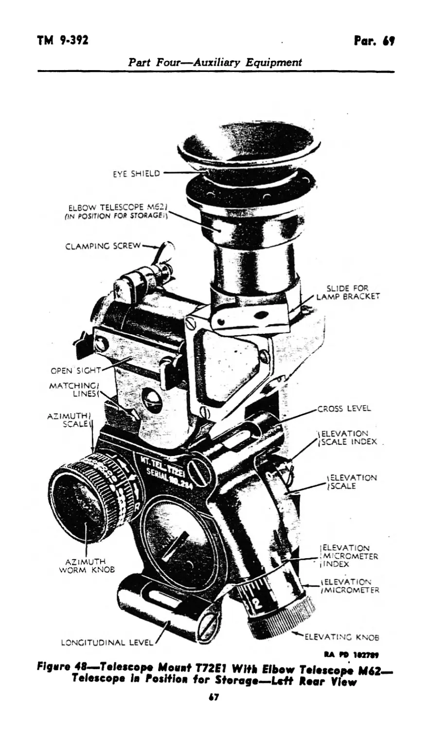
(3) Telescope mount T72E1 with elbow telescope M62
(fig. 44). The telescope mount T72E1 supports the elbow telescope
M62. The two instruments are not to be separated by the using arm
58
TM 9-392
Pars. 66-67
Part Four—Auxiliary Equipment
ELBOW TELESCOPE M62
MA PD 10J7S7
Figure 44—Telescope Mount T72E1 With Elbow Telescope M62
—Mounted on Rocket Launcher
personnel. The mount includes scales for setting elevation and
deflection.
67. MAINTENANCE.
a. Care in handling sighting and fire control instruments.
(1) Sighting and fire control instruments are, in general, rugged
and suited for the designed purpose. They will not, however, stand
rough handling or abuse. Inaccuracy or malfunctioning will result
from mistreatment.
(2) Unnecessary turning of screws, or other parts not incident
to the use of the instrument, is forbidden.
(3) Stops are provided on instruments to limit the travel of the
moving parts. Do not attempt to force the rotation of any knob be-
yond the stop limit
(4) When not in use, keep the instruments in the bracket in the
control box of the launcher, or covered and protected from dust and
moisture.
(5) Keep the instruments as dry as possible. If an instrument is
wet, dry it carefully before placing it in the control box.
St
Par. 67
TM 9-392
Part Four—Auxiliary Equipment
(6) Any instrument which indicates incorrectly or fails to func-
tion properly is to be turned in for repair by ordnance maintenance
personnel.
(7) No painting of sighting or fire control equipment by the
using arm personnel is permitted.
(8) When disengaging the azimuth mechanism of telescope
adapter M9 (on sightunit T127E1 and sightunit T128E1), push the
azimuth knob outward as far as it will go to be sure that the internal
worm and worm gear are completely disengaged. Do not allow the
worm to drag over the worm gear teeth as this will result in unneces-
sary wear of the parts.
(9) Clamping screws must not be tightened beyond a snug con-
tact. Excessive wear of threads and other damage to the instrument
are thereby eliminated.
b. Optical parts.
(1) To obtain satisfactory vision, it is necessaty that the exposed
surfaces of the lenses and other parts be kept clean and dry. Cor-
rosion and etching of the surface of the glass, which interfere with
vision, can be prevented or greatly retarded by keeping the glass
clean and dry.
(2) Under no circumstances should polishing liquids, pastes, or
abrasives be used for polishing lenses and windows.
(3) For wiping optical parts, use only lens tissue paper, specially
intended for cleaning optical glass. Use of cleaning cloths in the
field is not permitted. To remove dust, brush the glass lightly with
a clean artist camel’s-hair brush, and rap the brush against a hard
body in order to knock out the small particles of dust that cling to the
hairs. Repeat this operation until all dust is removed.
(4) Exercise particular care to keep optical parts free from oil
and grease. Do not wipe the lenses or windows with the fingers. To
remove oil or grease from optical surfaces, apply lens cleaning liquid
soap with a tuft of lens tissue paper, and wipe gently with clean lens
tissue paper. If this liquid is not available, breathe heavily on the
glass (provided the temperature of the surrounding air is above 32°F)
and wipe off with clean lens tissue paper. Repeat this operation sev-
eral times until the lens is dean.
(5) Below freezing temperatures, optics will be cleaned by rub-
bing gently with dry lens tissue paper. To remove oil film the instru-
ment will be brought into a warm enclosure and allowed to reach room
temperature before applying lens cleaning liquid soap.
(6) Moisture may condense on the optical parts of the instrument
when the temperature of the parts is lower than the surrounding air.
This moisture, if not excessive, can be removed by placing the instru-
ment in a warm place. Heat from strongly concentrated sources should
not be applied directly, as it may cause unequal expansion of parts,
M
ТМ 9-392
Pars. 67-68
Part Four—Auxiliary Equipment
thereby resulting in damage to optical parts and inaccuracies of
observation:
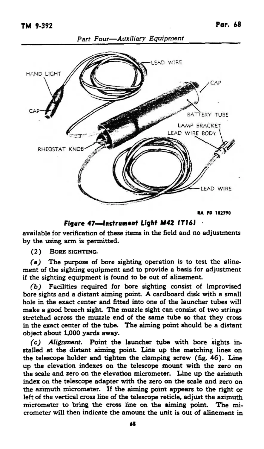
c. Batteriee.
(1) Batteries used in the instrument light should habitually be
removed whenever the lights are not in use. Chemical reaction set up
in an exhausted battery will damage the battery tube.
(2) The batteries for the instrument light M42 (T16) are con-
tained in the case of the instrument light. To remove the batteries,
unscrew the cap (fig. 47) and slide the two batteries out of the case.
When replacing batteries, be sure they go back in the case in the same
position as when removed. See that the cap is screwed on tightly to
assure contact with the battery terminals.
d. Lubrication. Keep a film of oil on the exposed bearing
surfaces of the mounting bracket. Use the lubricating oil for aircraft
instruments and machine guns. In areas of high humidity or extreme
moisture use preservative lubricating oil (medium) at temperatures
above 4-32°F. Extreme care should be taken not to apply lubricants
excessively. Excessive lubrication of certain parts may be as damaging
as the absence of any lubricant
68. SIGHTUNIT T128E1.
a. Installation and removal.
(1) Installation.
faj Remove the sightunit from the control box. Insert the dove-
tailed bracket on the telescope holder in the slot of the sight bracket
(fig. 43). When fully inserted, the latch will snap into place, securing
the instrument in position. Check to see that the sightunit is firmly
seated, latched, and free from motion.
(b) Loosen the winged clamp nut (fig. 43). Rotate the eyepiece
of the elbow telescope to the left and in a horizontal position. Tighten
the winged clamp nut This places the instrument in position ready
for operation.
(2) Removal.
(a) Press the latch toward the telescope and raise the complete
sightunit up and out of the dovetail on the sight bracket Place the
sightunit in position in the control box.
(b) When the sightunit is removed for storage in control box, it
will be necessary to loosen the winged clamp nut on the telescope
holder and turn the elbow telescope to a vertical position (fig. 45).
Tighten clamp nut before placing unit in control box.
b. Telescope mount T128E1 (fig. 43).
(1) The elevation scale is graduated in 100-mil steps between
minus 600 and plus 800 mils and numbered ev"'- 7^ 'ple
61
Par. 68
TM 9-392
Part Four—Auxiliary Equipment
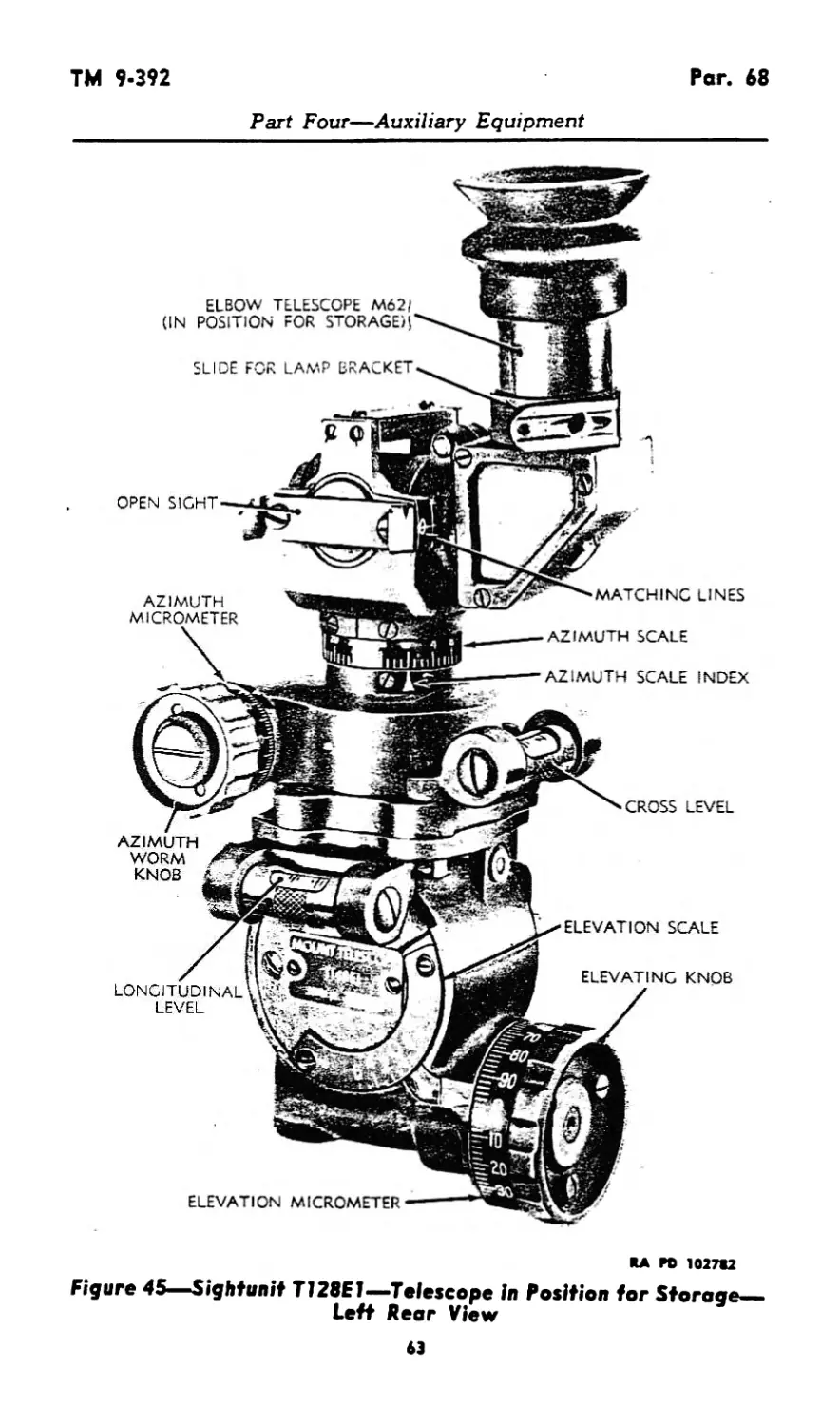
elevation scale is supplemented by the micrometer which is gradu-
ated in 1-mil steps from 0 to 100 mils and numbered every 10 mils.
(2) The longitudinal level is equipped with a rotating cover which
can be positioned to cover and protect the level vial when not in use.
(3) The required elevation setting is placed in the telescope
mount by turning the elevation knob (fig. 45) until the combined
reading of the elevation scale and micrometer (registered at the in-
dexes) total the correct amount. The launcher is then layed in eleva-
tion by turning the elevation mechanism of the launcher until the
longitudinal-level bubble is centered. During this operation the cross-
level nut (fig. 43) must be adjusted to hold the cross-level bubble (on
the adapter) centered.
(4) The sightunit must be removed from the launcher before
firing any rocket.
c. Telescope adapter M9 (fig. 43).
(1) The azimuth mechanism turns the telescope holder (upper
section of adapter) in azimuth through the use of the azimuth worm
knob (fig. 45).
(2) The azimuth scale is graduated in 100-mil divisions from
0 to 3200 in two consecutive semicircles and is numbered every 400
mils. The micrometer scale (on the azimuth worm knob) is gradu-
ated in 1-mil steps from 0 to 100 and numbered every 10 mils.
(3) Large changes in azimuth can be made rapidly by pushing
the azimuth worm knob outward to disengage the worm, turning the
unit by hand, then reehgaging the worm to complete the setting.
The setting is then completed by turning the azimuth worm until the
combined reading of the azimuth scale and micrometer (registered
at the indexes) total the required azimuth setting.
(4) The cross level is equipped with a cover which can be rotated
to protect the level vial when the unit is not in use. The movement
of the cross level is controlled by turning the cross-level nut on the
sight bracket. The sightunit is cross-leveled when the bubble is
centered.
d. Elbow telescope M62 (fig. 43).
(1) Description. The elbow telescope M62 is a 3-power elbow
telescope with a field of view of 12 degrees 12 minutes. The telescope
is a fixed focus type, designed for normal eyesight and for ranges
ordinarily encountered. The reticle pattern consists of a vertical and
horizontal cross line. The cross line is superimposed upon the image
when sighting through the telescope. A window below the eyepiece
permits illumination of the reticle by an external light source. The
telescope is used with the eyepiece extended in a horizontal position
(fig. 45).
(2) Elevating movement. The telescope can be moved freely
42
TM 9-392
Par. 68
Part Four—Auxiliary Equipment
RA PD 1027S2
Figure 45—Sightunit T128E1—Telescope in Position for Storage-
Left Rear View
63
Par. 68
TM 9-392
Part Four—Auxiliary Equipment
RA ГО 102713
Figure 46—<Sighfunit TJ28E1—Telescope in Position for Storage—•
Right Front View
in elevation by loosening the elevation clamping screw (fig. 46), on
the telescope holder or it can be locked at any elevation setting by
tightening the screw. The matching lines near the open sights show
the normal (zero elevation) position of the telescope in the holder.
The telescope clamp screw, when loosened, permits the telescope to
be turned about its objective axis. For operation, the telescope should
be in the horizontal position (fig. 43) with the eyepiece turned to the
left
e. Instrument light M42 (T16) (fig. 47). The instrument
light M42 (T16) consists of a battery box containing two flashlight
batteries and two extension cords. One cord carries a light which
can be fastened to the elbow telescope for illumination of the reticle,
and the other cord carries a hand light for illumination of the scales
on the telescope mount. The instrument light is controlled by a knob
on the battery box. The battery box can remain in the control box
at all times. The reticle lamp bracket slides into a dovetail slot on
the elbow telescope (fig. 43).
f. Tests and adjustments.
(1) General. Proper alinement of the levels, pivots, and elbow
telescope is accomplished at the factory. No facilities are ordinarily
64
ТМ 9-392
Par. 68
Part Four—Auxiliary Equipment
RA ГО 102790
Figure 47—Instrument Light M42 (776)
available for verification of these items in the field and no adjustments
by the using arm is permitted.
(2) Boresighting.
(a) The purpose of bore sighting operation is to test the aline-
ment of the sighting equipment and to provide a basis for adjustment
if the sighting equipment is found to be out of alinement.
(b) Facilities required for bore sighting consist of improvised
bore sights and a distant aiming point. A cardboard disk with a small
hole in the exact center and fitted into one of the launcher tubes will
make a good breech sight. The muzzle sight can consist of two strings
stretched across the muzzle end of the same tube so that they cross
in the exact center of the tube. The aiming point should be a distant
object about 1,000 yards away.
(c) Alignment. Point the launcher tube with bore sights in*
stalled at the distant aiming point Line up the matching lines on
the telescope holder and tighten the clamping screw (fig. 46). Line
up the elevation indexes on the telescope mount with the zero on
the scale and zero on the elevation micrometer. Line up the azimuth
index on the telescope adapter with the zero on the scale and zero on
the azimuth micrometer. If the aiming point appears to the right or
left of the vertical cross line of the telescope reticle, adjust the azimuth
micrometer to bring the cross line on the aiming point. The mi-
crometer will then indicate the amount the unit is out of alinement in
И
Pars. 68*69
TM 9-392
Part Four—Auxiliary Equipment
azimuth. If the aiming point appears above or below the horizontal
cross line, adjust the elevation micrometer to bring the cross line on
the aiming point. The micrometer will then indicate the amount the
unit is out of alinement in elevation.
(d) No bore sighting adjustments are permitted on the launcher
by the using arm personnel, but if the adjustment is out of alinement
by more than 3 mils, the ordnance maintenance personnel should be
notified.
69. TELESCOPE MOUNT T72E1 WITH ELBOW TELESCOPE
M62 AND INSTRUMENT LIGHT M42 (T16).
a. General.
(1) The elbow telescope M62 and the instrument light M42 are
the same as those used with sightunit T128E1 (par. 68).
• (2) Tests and adjustments are the same as those applying to
sightunit T128E1 (par. 68).
b. Installation and removal.
(1) Installation.
(a) Remove the sightunit from the control box. Insert the dove-
tailed bracket on the telescope holder in the slot of the sight bracket
(fig. 44). When fully inserted, the latch will snap into place, securing
the instrument in position. Check to see that the sightunit is firmly
seated, latched, and free from motion.
(b) Loosen the winged clamp nut (fig. 49). Rotate the eyepiece
of the elbow telescope to the left and in a horizontal position. Tighten
the winged clamp nut This places the instrument in position ready for
operation.
(2) Removal.
(a) Press the latch toward the telescope and raise the complete
sightunit up and out of the dovetail on the sight bracket Place the
sightunit in position in the control box.
(b) When the sightunit is removed for storage in control box, it
will be necessary to loosen the winged clamp nut on the telescope
holder and turn the elbow telescope to a vertical position (fig. 48).
Tighten clamp nut before placing unit in control box.
c. Telescope mount T72E1.
(1) The elevation scale is graduated in 10-degree steps between
0 and 40 degrees and is supplemented by a micrometer graduated
in %-degree (15-minute) steps.
(2) The longitudinal level is equipped with a rotating cover
which can be positioned to cover and protect the level vial when not
TM 9-392
Par. И
Part Four—Auxiliary Equipment
EYE SHIELD
ELBOW TELESCOPE M62(
(IN POSITION FOR STORAGE.»
CLAMPING SCREW
AZIMUTH
WORM KNOB
LONGITUDINAL level
l ELEVATION
/MICROMETER
ELEVATING KNOB
; ELEVATION
. MICROMETER
/INDEX
SLIDE FOR
LAMP BRACKET
LEVEL
\ ELEVATION
(SCALE INDEX
t ELEVATION
(SCALE
OPEN SIGHT
matching;
A P© 1S27W
Figere 48—Telescope Moeet T72E1 With Elbow Telescope M62—
Telescope le Position for Storage—Lett Rear View
Par. 69
TM 9-392
Part Four—Auxiliary Equipment
.ELBOW TELESCOPE M62
i(IN POSITION FOR storage;
BRACKET
LONGITUDINAL LEVEL
MICROMETER KNOB
Clamping
CROSS LEVEL
CLAMPING
LATCH
KA KD 1027M
Figure 49—Telescope Meant T72E7 With Elbow Telescope M62—
Telescope in Position for Storage—Right Front View
in use. When the level bubble is centered, it indicates that the
launcher is elevated to the angle indicated on the elevation scale
and micrometer.
(3) The required elevation setting is placed in the telescope
mount by turning the elevation knob (fig. 48) until the combined
reading of the elevation scale and micrometer (as registered at the
indexes) total the correct amount.
(4) The launcher is then layed in elevation by turning the eleva-
tion mechanism of the launcher until the longitudinal-level bubble
centers. During the operation, the cross-level nut on the sight bracket
(fig. 44) must be adjusted to hold the cross-level bubble centered.
(5) The deflection knob scale is graduated in 5-mil steps and
numbered every 10 mils. Direction of rotation for left and right
deflection is indicated by the letters “L” and “R” and arrows near the
index. Deflection is limited to plus or minus 150 mils, and zero indi-
cation sets the line of sight parallel to the launcher tubes.
(6) The required deflection is set by turning the deflection knob
until the correct amount registers at the index. The traversing hand-
wheel of. the launcher is then turned until the vertical line of the
elbow telescope is laid on the aiming point or aiming post
M
ТМ 9-392
Per. 70
APPENDIX
Section XXVIII
SHIPMENT AND STORAGE
70. DOMESTIC SHIPMENT AND LIMITED STORAGE.
a. General.
(1) The 4.5-inch multiple rocket launcher T66 and T66E2 will
be shipped and stored in the traveling position.
(2) Preparation for domestic shipment and limited storage will
be the same. All precautions must be taken to prevent corrosion of
materiel and deterioration of rubber during storage.
(3) Materiel in limited storage is that materiel which is out of
service for less than 30 days or materiel that must be ready for opera-
tion on call.
b. Materials required. Materials required for preparation for
shipment and storage specified throughout this section are listed in
section XI, with the exception of items listed below.
COMPOUND, rust preventive, light
COMPOUND, rust preventive, thin film
TAPE, adhesive, non-hygroscopic, О 2D.
c. Cleaning.
(1) The launchers will be thoroughly cleaned and made free of
all foreign matter with dry-cleaning solvent, soap solution or soda-
ash, as follows:
(a) Apply dry-cleaning solvent by scrubbing with a brush or
wiping with a clean cloth. Dry all parts thoroughly.
(b) Apply either a warm soda-ash or a soap solution by brushing
or scrubbing the surfaces thoroughly until all traces of contamination
have been removed. The surfaces will then be rinsed with clean warm
water and thoroughly dried. For general cleaning purposes, soda-ash
solution consists of ¥2 pound of soda-ash in 2 gallons of warm water.
For cleaning launcher bores, solution will consist of ¥2 pound of soda-
ash in 1 gallon of warm water. Soap solation consists of 1 pound of
castile or issue soap in chip form dissolved in 4 gallons of hot water.
(2 ) Rifle-bore cleaner is used for cleaning launcher bores. It may
be used in lieu of dry-cleaning solvent to clean other launcher parts
and mechanisms. The cleaner is most efficiently used when undiluted,
but when necessary to conserve supply, it may be diluted up to 50
percent with water. (Refer to section XV.) The standard bore
brushes and cleaning accessories supplied with materiel are satisfac-
tory for cleaning bores with rifle-bore cleaner. NOTE: Under no
circumstances will a hose, either normal or high pressure, be used in
cleaning any sighting equipment or any fire control instruments. Be-
fore washing, take off removable sighting equipment from the materiel
49
Par. 70
TM 9-372
Appendix
to be cleaned. In cases where it is not removable, take care to cover
the parts properly.
(3) Avoid contact of bare hands with cleaned surfaces.
d. Lubrication. Launchers will be lubricated before rail ship-
ment or storage as prescribed in section XII.
e. Painting. All painted metal surfaces that have become
pitted or rusted will be cleaned with aluminum oxide abrasive cloth
or crocus cloth and repainted where necessary.
f. Application of preservatives. Preservatives will be applied
immediately after cleaning and drying as a rust stain will form if
materiel is handled between operations. Rust-preventive compound
(light) used herein must be heated for proper consistency before
application. For methods of heating and application of rust-preven-
tive compounds, refer to TM 9-850, dated 24 August 1944.
(1) Launcher bores. Swab each launcher bore thoroughly,
using a ramrod and clean cloths soaked in heated rust-preventive
compound (light). Repeat operation until all interior surfaces of
the bores are thoroughly covered with a protective coating of the
preservative.
(2) Exterior unpainted surfaces. Use rust-preventive com-
pound (light) on exterior unpainted operating or machined surfaces
from which preservatives will be completely removed before materiel
is placed in operation.
g. Sealing.
(1) Launcher tubes.
(a) Seal front of launcher tubes by applying one long б-inch wide
strip of nonhygroscopic adhesive tape horizontally across eight tubes,
starting left to right.
(b) Overlap this strip with a 4-inch wide strip completely sealing
eight tubes horizontally.
(c) Repeat operation for remaining 16 tubes.
(d) Seal vertically by applying б-inch and 4-inch wide strips
across horizontal strips completely covering all 24 tubes.
(e) Spray over tape with rust-preventive compound (thin film).
(f) Repeat operations (steps (a) to (e), above) for sealing rear of
launcher tubes.
(2) Control box. Remove firing handle, firing cable, telescope
mount, telescope, etc., and place in control box. Seal all edges
of control box with nonhygroscopic adhesive tape.
h. Covers. Install covers provided with the materiel and fasten
securely.
70
TM 9-392
Pars. 70-71
Appendix
i. Gun book.
(1) During transfer or shipment, the gun book must be kept in
a waterproof envelope fastened to the cannon with nonhygroscopic
adhesive tape.
(2) Under one of the wrappings of tape, one end of a small tab
will be inserted, reading “Gun book here.”
j. Inspection instructions.
(1) General. A systematic inspection will be made before
shipment or storage. All missing or broken parts will be promptly
repaired and/or replaced. If repairs cannot be made prior to placing
materiel in storage, a tag will be attached to materiel specifying the
repairs needed, and a written report of these items will be made to
the officer in charge of the materiel.
(2) Limited storage. A visual inspection will be made weekly
during storage to determine general condition. If corrosion is found
on any part, remove the rust spots and treat with the prescribed
preservative.
k. Removal from storage.
(1) Remove all seals and tape. Remove preservatives, using
dry-cleaning solvent. Solutions of soda-ash or soap may be used as a
substitute. Dry thoroughly after application of cleaning material
and lubricate in accordance with instructions prescribed in section ХП.
(2) Repair and/or replace all items tagged in accordance with
subparagraph j (1), above.
71. LOADING RULES AND BLOCKING REQUIREMENTS FOR
RAIL SHIPMENT.
a. General. Materiel to be loaded and blocked on railroad cars
for rail shipment will be prepared in accordance with instructions
given in paragraph 71. All loading and blocking instructions as speci-
fied herein are minimum. Additional blocking as required may be
added at the discretion of the officer in charge.
b. Inspection. Railroad cars must be inspected to see that they
are suitable to carry loads safely to destinations. Floors must be
sound and all loose nails or other projections, not an integral part of
the car, will be removed. Nails, bolts, etc., necessary in car construc-
tion when loose, will be made tight rather than removed.
c. Ramps. Permanent ramps will be used for loading materiel,
but when such ramps are not available, they may be improvised from
rail ties and other available lumber.
d. Handling.
(1) Cars loaded in accordance with specifications given herein
must not be handled in hump switching.
71
Par. 71
TM 9-392
Appendix
(2) Cars must not be cut off while in motion, and must be coupled
carefully to avoid all unnecessary shocks.
(3) Cars must be placed in yards or on sidings so that they will
be subjected to as little handling as possible. Separate track or tracks,
when available, must be designated at terminals, classification or
receiving yards for such cars, and cars must be coupled at all times
during such holding and hand brakes set.
e. Clearing limits. The height and width of load must be within
the clearance limits of the railroads over which it is to be moved.
Army and railroad officials must check all clearances prior to each
move.
f. Maximum load weights. In determining the maximum
weight of load, the following shall govern, except where load weight
limit has been reduced by the car owner.
Marked Capacity Total Wolaht of
of C« Car and Load Load Weighfs
(1b) (lb) (lb Ion H. wt. of car)
40,000 66,000 66,000
60,000 103,000 103,000
80,000 136,000 136,000
100,000 169,000 169,000
140,000 210,000 210,000
200,000 251,000 251,000
EXAMPLE
Lb
Capacity of car.............................. 100,000
Total weight of car and load................. 169,000
*Light weight of car (to be subtracted)...... 37,000
Permissible weight of load................... 132,000
g. Brake wheel clearance (A, fig. 50). Load should clear the
brake wheel as much as possible, but must not be less than 4 inches
below, nor less than 6 inches above, in back and on both sides of the
brake wheel. Brake wheel clearance will be increased as much as is
consistent with proper location of load.
h. Distribution of load. Materiel must be so placed on the car
that there will not be more weight on one side of the car than on the
other. One truck of the carrying car must not carry more than one-
half of the load weight. NOTE: When loading railroad cars, materiel
will be so loaded as to require a minimum number of cars. To accom-
plish this, various types of materiel may be loaded on the same car
provided all have the same destination.
i. Tire pressure. For shipment by rail, the tire pressure will
be increased 10 pounds per square inch above normal.
j. Type of car. Flat or drop-end gondola cars may be used.
k. Blocking. Method of blocking the 4.5-inch multiple rocket
launchers Тбб and T66E2 will be the same. All blocking pieces will
•This marking is stenciled oe each sida of car as “LT. WT.”
n
TM 9-392
Рог. 71
Appendix
be of sound straight-grained wood. (All item reference letters given
below refer to the details and locations in figure 50.)
(1) Blocks B, pattern 3 (6 in. x 8 in. x 24 in., four required).
Locate 45-degree portion of block in front and rear of wheels. Nail
heel of block to car floor with three fortypenny cement-coated nails
and toenail outside portion to car floor with two fortypenny cement-
coated nails before items C are applied.
(2) Cleats C, pattern 2 (2 in. x 4 in. x 36 in., four required).
Locate two cleats against the outside face of wheels. Nail lower cleat
to car floor with four thirtypenny cement-coated nails and top cleat
to the lower cleat and car floor with four thirtypenny cement-coated
nails.
(3) Supports D, pattern 7 (length to be l/t inch longer than
the distance between the axle and car floor to partially relieve weight
from the tires, two required). Place support D under the axle near
the inside face of each wheel. Nail each support to the car floor with
six fortypenny cement-coated nails.
(4) Axle strapping E (two required). Locate two 1-inch No.
14 B. W. gage, hot rolled steel bandings over axle and secure to car
floor with anchor plates. Nail anchor plates to car floor with eight
twentypenny cement-coated nails. NOTE: Four strands, No. 8 gage,
black annealed wire or wires of equivalent strength, may be substi-
tuted for steel banding. Wires will be secured to car floor by placing
a cleat (2 in. x 4 in. x 18 in.) on top of wires and cleat will be nailed
to car floor with four thirtypenny cement-coated nails.
(5) Blocks F (6 in. x 6 in. x 24 in., four required). Place one
block F against the front and rear of each spade. Toenail blocks to
car floor with six fortypenny cement-coated nails. Blocks will be cut
to fit contour of spades.
(6) Cleats H, pattern 1 (2 in. x 4 in. x 12 in, two required).
Place one cleat H against each side of spade and nail to car floor
with three thirtypenny cement-coated nails.
(7) Stakes J, pattern 8 (4 in. x 5 in. x 48 in, two required).
Locate in stake pocket of car one-third the distance from the end of
trail to the center of the wheels, stake to extend 4 inches below pocket.
Drive one fortypenny cement-coated nail into each stake J directly
below stake pocket and clinched over outside of pocket.
(8) Trail strapping S. Secure each trail of the carriage using
six strands, two wrappings of No. 8 gage, black annealed wire looped
around and over the top of rear end of trail, and secure to stake
pockets on both sides of the car. Twist-tie wires with rod or bolt.
NOTE: When a box car or drop-end gondola.car is used, apply strap-
ping in a similar fashion, and attach to the floor by use of blocking or
anchor plates.
П
Appendix
л po 102m
Fkiir. КЛ___AJ.MImI. *мАж« ITZZ____________________________________________л_ч______ «•__
ТМ 9-392
Per. 72
Appendix
72. METHODS OF SLINGING 4.5-INCH MULTIPLE ROCKET
LAUNCHERS T66 AND T66E2.
a. General.
(1) These instructions prescribe procedures, methods, and prac-
tices to be followed when the materiel is hoisted, and describe the
proper attachment points for slings to permit the materiel to be
hoisted in its normal position.
(2) Covers supplied with materiel will be installed and securely
fastened.
(3) If operations embrace deep water fording, materiel will be
prepared in accordance with TM 9-2853, “Preparation of Ordnance
Materiel for Deep Water Fording.”
(4) For methods in stevedoring, refer to TM 55-310, “Steve-
doring.”
b. Sling methode.
NOTE: Due to varying conditions encountered in the field, any of
the following procedures may be used, where applicable.
(1) Method I (fig. 51). Method I employs the following
materials:
(a) Cable slings (heavy enough to support materiel).
(b) Shackles (placed between lifting cables and slings).
(c) Lifting cables.
(d) Lifting hook.
(e) Cargo runners.
(f) Spreaders (4 in. x 6 in., length as required) are used between
cables to. obtain a better balance and to provide clearance between
slings and* materiel to prevent damage when materiel is hoisted.
Spreaders consist of two pieces of oak or other hardwood with open
ends as shown in figure 51, and are positioned on the cables leading
from the lifting hook at a point which will provide clearance between
slings and materiel. Slings are placed around materiel at the proper
points of balance and attached to the shackles on the lifting cables.
(2) Method II (fig. 51). Special care must be exercised, when
this method is used, to see that proper clearance for fire control
brackets, gears, and operating surfaces is maintained when materiel
is hoisted clear of ground. Method II employs the following materials:
(a) Cable slings (heavy enough to support materiel).
(b) Shackles (placed between lifting cables and slings).
(c) Lifting cables.
(d) Lifting hook.
(e) Cargo runners.
(3) Method III (fig. 51). Method III employs the following
materials:
75
SPREADERS
4X6 INCH
Figure 51—Sling Mifhodi In Holttiaf AHIIItry Maferlel
RA PD 14115
8.
•
W
О
1ч>
TM 9-392
Per. 72
Appendix
('aJ Cable slings (heavy enough to support materiel).
(b) Lifting hook.
(c) Cargo runners.
(d) Spreaders (4 in. x 6 in., length as required) are used between
cables to obtain a better balance and to provide clearance between
slings and materiel to prevent damage when materiel is hoisted.
Spreaders consist of two pieces of oak or other hardwood with open
ends as shown in figure 51, and are positioned on the cables leading
from the lifting hook at a point which will provide clearance between
slings and materiel.
(4) Method IV (fig. 51). Special care must be exercised, when
this method is used, to see that proper clearance for fire control
brackets, gears, and operating surfaces is maintained when materiel is
hoisted clear of ground. Method IV employs the following materials;
(a) Cable slings (heavy enough to support materiel).
(b) Lifting hook.
(c) Cargo runners.
c. Cautions during hoisting of materiel.
(1) Before attempting to hoist materiel, an examination of hoist-
ing cables must be made to determine their condition. If strands
of cable are broken at any point, a new cable must be substituted.
Kinked cables which will not straighten out without damage will
not be used.
(2) Under no circumstances must materiel be hoisted when it is
found that all weight is balanced on one sling (other sling being loose).
Materiel must be lowered to the ground and slings placed in the
proper position.
(3) Do not place slings around launcher tubes for hoisting
purposes.
(4) All damageable instruments such as fire control equipment,
gun sights, etc., must be removed from materiel and securely stowed.
It is imperative that all stowage boxes, tires, or other loose equipment
be securely strapped to materiel prior to movement.
(5) If the under side of materiel has sharp edges at the points
where slings are placed, insert dunnage consisting of wood blocks,
sacking, clean cloth, or similar material between the slings and ma-
teriel in order to prevent cable strands from cutting or slipping.
(6) Attach guy lines to materiel before lifting. Guide materiel
during hoisting to prevent damage caused by striking any nearby
object or structure.
d. Method of slinging 4.5-inch multiple rocket launchers, T66
and T66E2 (figs. 51 and 52). This type of lift requires the use of
two slings and one extra cable.
77
Per. 72
TM 9-392
Appendix
LIFTING CABLE
SLING
RA PD 102973
Figure 52—Method of Slinging 4.5-inch Multiple Rocket
Launcher T66
BETWEEN
LIFTING CABLE
AND SLING
NOTE 1-SUITABLE DUNNAGE WILL
BE PLACED BETWEEN
CABLE ANO MATERIEL
NOTE 2-ATTACH GUY LINES TO
MA TERIEL BEFORE LIFTING
GUIDE MATERIEL DURING
HOISTING TO PREVENT
DAMAGE CAUSED BY STRIKING
ANY NEARBY OBJECT OR
STRUCTURE.
(1) Detach one end of both cable slings from the shackles on
lifting cables.
(2) Place the detached end of slings around axle close to wheels
and attach to shackles (fig. 52).
(3) Place the third cable sling around trails, through lifting
brackets just ahead of the spades, and attach both ends to shackle
on lifting cable.
(4) Locate dunnage as described in paragraph 72 c (5).
(5) Attach guy lines (par. 72 c (6)), and hoist materiel slowly,
observing proper balance (CAUTION, par. 72 c (2)).
78
TM 9-392
Fars. 73-75
Appendix
Section XXIX
REFERENCES
73. PUBLICATIONS INDEXES. The following publications in-
dexes should be consulted frequently for latest changes or revisions
of reference given in this section and for new publications relating
to materiel covered in this manual:
a. Ordnance Supply Catalog Index........... ASF Cat ORD 2
b. Ordnance Major Items and Combinations,
and Pertinent Publications ................ SB 9-1
c. List and Index of War Department Publica-
tions (listing new AR’s, CCBP’s, Cir’s,
Forms, FM’s, FM’s, FTs, GO’S, LO’s,
MR’s, MTP’s, MWO’s, PCT’s, SB’s, TB’s,
TC’s, RR’s, TM’s, TR’s, WDB’s, WDP’s,
T/O fc E’s, and similar publications)...... FM 21-6
d. List of Training Films, Film Strips, and
Film Bulletins ............................ FM 21-7
e. Military Training Aids (listing graphic
training aids, models, devices, and dis-
plays) .................................... FM 21-8
74. STANDARD NOMENCLATURE LISTS.
a. Cleaning and preserving.
Cleaning, preserving and lubricating ma-
terials; recoil fluids, special oils, and
miscellaneous related items ....ASF Cat ORD 5 SNL K-l
b. Launcher materiel.
Launcher, rocket 24-tube, 4.5-in,
Тбб ........................ ASF Cat ORD (♦) SNL C-67
75. EXPLANATORY PUBLICATIONS.
a. Army regulations.
Qualifications in Arms and Ammunition
Training Allowances .................... AR 775-10
Range Regulations for Firing Ammunition
for Training and Target Practice ....... AR 750-10
< •) See ASF Catalog, Ord 2 Index, for published pamphleti of the Ordnance Supply Catalog.
7»
Pars. 75-76
TM 9-392
Appendix
b. Decontamination.
Decontamination . . .................. TM 3-220
Defense Against Chemical Attack......... FM 21-40
c. Painting, cleaning, preserving, and
lubrication.
Cleaning, Preserving, Lubricating and Re-
lated Materials Issued for Ordnance
Materiel .................................... TM 9-850
Maintenance and Care of Hand Tools...... TM 9-867
Maintenance and Care of Pneumatic Tires
and Rubber Treads..................... TM 31-200
Preparation of Ordnance Materiel for Deep
Water Fording......................... TM 9-2853
d. Miscellaneous.
Dictionary of United States Army Terms. .. TM 20-205
e. Standard Nomenclature Lists and Technical
Manuals covering auxiliary equipment.
Ammunition, General .................... TM 9-1900
Auxiliary Fire Control Instruments (Field
Glasses, Eyeglasses, Telescopes and
Watches) ................................ TM 9-575
Rockets ................................. TM 9-1950
Rockets, Ammunition... ASF Cat ORD 11 SNL S-9
f. Storage and shipment instructions.
Ordnance Packaging and Shipping (Posts,
Camps, and Stations)......................... TM 9-2854
g. Firing Tables.
RT4.5— С—1
Graphical firing table T2
76. LIST OF FORMS.
Form, Government, War Department,
Artillery Gun Book............... O.O. No. 5828 (blank)
Ordnance Safety Manual................ O.O. Form 7224
Unsatisfactory Equipment Report....W.D. AGO. Form 468
•0
TM 9-392
INDEX
A
Accessories ....................... И
Ammunition
demolition...................... 31
descripton ..................... 49
identification and authorised
rounds..................... 52
packing ........................ S7
preparation for firing......... 53
Ammunition tables .................53
Artillery Gun Book................ 1
Auxiliary equipment
general discussion...............49
operation...................... 27
В
Batteries ....................... 61
Blocking requirements for rail
“ shipment....................... 71
Bore cleaning......................41
. c
Carriage
general discussion ..............43
maintenance .....................44
Cleaning ......................... 37
Control box....................... 44
D
Demolition to p.’event enemy use. . 30
E
Equipment
operation (auxiliary)........... 27
service upon receipt
new ......................... 12
used......................... 13
(See also Sighting equipment and
Fire control equipment)
Elevating controls ............... 13
Elevating mechanism................46
F
Field report of accidents.......... 2
Fire control equipment
arrangement and use............. 58
general discussion.............. 57
lubrication..................... 61
Page
Firing controls, operation......... 13
Firing mechanism
general discussion ...............42
maintenance .................... 43
Firing pedestal................... 47
Fuses.............................. 54
I
Instrument light M42(T16)......... 64
Instruments, operation............. 16
L
Launcher, rocket (See Rocket
launchers)
Loading rules..................... 71
Lubrication, general instructions... 34
Lubrication Order ................ 32
M
Maintenance
general.......................... 32
preventive.......................38
Malfunctions end corrections.......39
Maximum load weights............. 72
о
Operation under unusual conditions 28
Optical parts..................... 60
9
Pedestal controls, operation....... 16
R
Rifle bora cleaner.................41
Rocket launchers
demolition........................31
description ..................... 2
firing ....................... 26
identification, data, and differ-
ences in models.............. 9
Loading......................... 25
placing in:
firing portion................ 16
traveling position . . . . ....... 27
shipment and storage
cautions during hoisting . . .... 77
methods of slinging...........75, 77
traversing and elevating . . . .... 22
•1
TM 9*392
Index
R—Confd» Fee*
Rockets
differences in models and prepara-
tion for firing............... S3
packing .................... 57
precautions in handling...... 54
s
Service upon receipt of equipment 12
Shipment and storage.............. 69
Sight bracket..................... 47
Sighting equipment
arrangement and use............... 58
data ........................... 10
general discussion ............. 57
lubrication .................... 61
maintenance .................... 59
Sight unit
installation and removal.......... 61
teats and adjustments........... 64
Spare parts, organizational....... 10
T Pegs
Telescope, elbow, M62 ........... 62
Telescope adapter M9............. 62
Telescope mount Т128Б1........... 61
Telescope mount T72E1 W/tele-
scope M62 and instrument
light M42 (T16) ................. 66
Tie rods......................... 44
Tools .......................... 10
Trails .......................... 44
Traversing controls ............. 13
Traversing mechanism............. 47
Tube» cleaning .................. 29
Tube duster, maintenance.......... 40
Tube cluster traveling lock....... 13
и
Unsatisfactory equipment record . . 2
w
Wheels
general discussion ............... 47
maintenance ................... 48
U.S. GOVERNMENT PRINTING OFFICE: O—1952 .
82