/


Text
ТМ 9-294
* RESTRICTED
WAR DEPARTMENT
TECHNICAL MANUAL
2.36-INCH A.T. ROCKET
LAUNCHER M1A1
27 SEPTEMBER 1943
★ Dissemination of restricted matter — The information contained in re-
stricted documents and the essential characteristics of restricted materiel
may be given to any person known to be in the service of the United States
and to persons of undoubted loyalty and discretion who are cooperating in
Government work, but will not be communicated to the public or to the press
except by authorised military public relations agencies. (See also paragraph
IB b, AR 380-5, 28 September 1942.)
♦ТМ 9-294
★ RESTRICTED
TECHNICAL MANUAL)
No. 9-294 f
WAR DEPARTMENT
Washington, 27 September 1943
2.36-INCH A T. ROCKET LAUNCHER M1A1
Prepared under Hie direction of the
Chief of Ordnance
CONTENTS
Paragraphs Pages
Section I. Introduction......................... 1-4 3-5
II. Description and functioning.......... 5-6 6-7
III. Operation........................... 7-11 8-16
IV. Malfunctions and corrections.......12-14 17-18
V. Care and preservation...............15-16 19
VI. Disassembly and assembly........... 17-19 20-26
VII. Ammunition......................... 20-27 27-32
VIII. Inspection ....................... 28-29 33
IX. Maintenance and repair............. 30-31 34-36
X. Operation under unusual conditions. 32-34 37-38
XI. Painting .......................... 35-39 39-40
XII. Storage and shipment................40-41 41-46
XIII. Reference......................... 42-43 47
Index.................................................... 48-49
★ Dissemination of restricted mutter -The information contained in restricted documents
and the essential characteristics of restricted materiel may be given to any person known to
be in the service of the United States and to persons of undoubted loyalty and discretion who
ere cooperating in Government work, but will not be communicated to the public or to the
press except by authorised military public relations agencies. (See also paragraph 18 b,
AR 380-5, 28 Sept ember 1942.)
*This manual
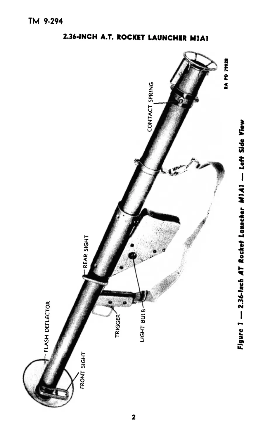
Figure 1 — 2.36-lnch AT Rocket Launcher M1A1 — Left Side View
2.36-INCH A.T. ROCKET LAUNCHER Ml Al
ТМ 9-294
1-4
Section I
INTRODUCTION
Рог 09га ph
Scope .................................................... 1
Characteristics .......................................... 2
Data ..................................................... 3
Precautions .............................................. 4
1. SCOPE.
a. This manual is published for the information and guidance of
personnel charged with the operation and maintenance of the 2.36-
inch AT Rocket Launcher M1A1. It contains information required
by the using arms to identify, use, care, and preserve the materiel
and the ammunition used therewith. In addition, it contains informa-
tion required by ordnance personnel for the maintenance and repair
of the materiel.
2. CHARACTERISTICS (figs. 1 and 2).
a. The 2.36-inch AT Rocket Launcher Ml Al is an electrically
operated weapon of the open tube type. It is fired from the shoulder
in the standing, kneeling, sitting, or prone positions. It is used to
launch high-explosive rockets against tanks, armored vehicles, pill
boxes, and emplacements. The rockets weigh approximately ЗУ2
pounds and are capable of penetrating heavy armor at angles of
impact up to 30 degrees. The weapon can be aimed up to distances
of 300 yards. Greater ranges may be obtained by estimating the angle
of elevation. The maximum range is 700 yards.
3. DATA.
Length of launcher (approx.)..........................54.5 in.
Weight of launcher (approx.).........................13.26 lb
Internal diameter ....................................2.37 in.
Length of rocket......................................21.6 in.
Weight of rocket.......................................3.5 lb
Muzzle velocity.................................265 ft per sec
4. PRECAUTIONS.
a. Do not expose rockets to the sun except when immediately ready
to load. Store rockets in their containers in shaded places.
b. Do not allow a rocket to remain in a hot launcher prior to firing.
c. Rockets as shipped contain a small cardboard plug cemented
over the nozzle in the forward end of the fin assembly. This prevents
entry of moisture or dirt into the propellent charge during storage
and handling. Do not use any rocket with a missing cardboard plug.
Do not remove the plug.
3
FACE GUARD
BARREL REINFORCING WIRE
RA PD 71Ю
-TRIGGER GUARD
SLING
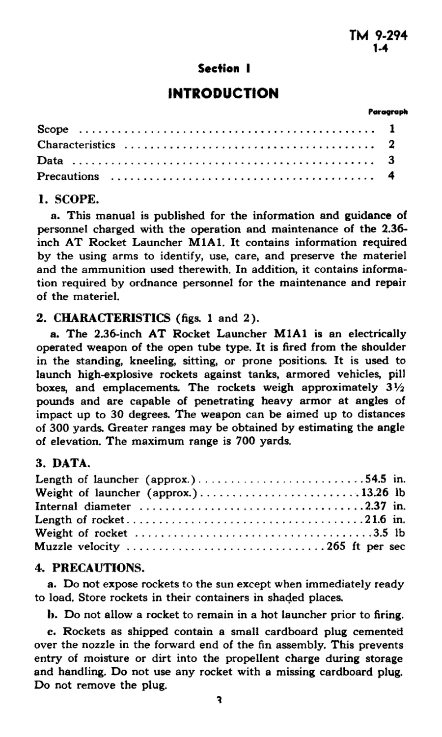
Figure 2 — 2.36-1лсй AT ftocbet LaRRcber Ml Al — Right Side View
2.36-INCH A.T. ROCKET LAUNCHER M1A1
ТМ 9-294
4
INTRODUCTION
d. Since the fuze of the rocket is quite sensitive, it is important that
the rocket be handled carefully after removal of the safety pin, and
that it not be dropped, A fall on its nose, after removal of the safety
wire, will cause detonation.
e. The burning time of the propellant is approximately 0.02 to
0.03 second, and combustion is complete before the rocket leaves the
muzzle, hence there is no flash. Occasionally, however, the burning
may, for some reason, be retarded, creating a backflash as the
rocket leaves the muzzle. This occurs during cold weather but may
also occur at other times. The firer should be protected against this
by gloves or cloth wrapped around the hands, goggles, or other pro-
tective equipment, such as a gas mask. This precaution is especially
important in cold climates or when no flash deflector is available.
It is also recommended that both the firer and the loader wear steel
helmets when using the launcher.
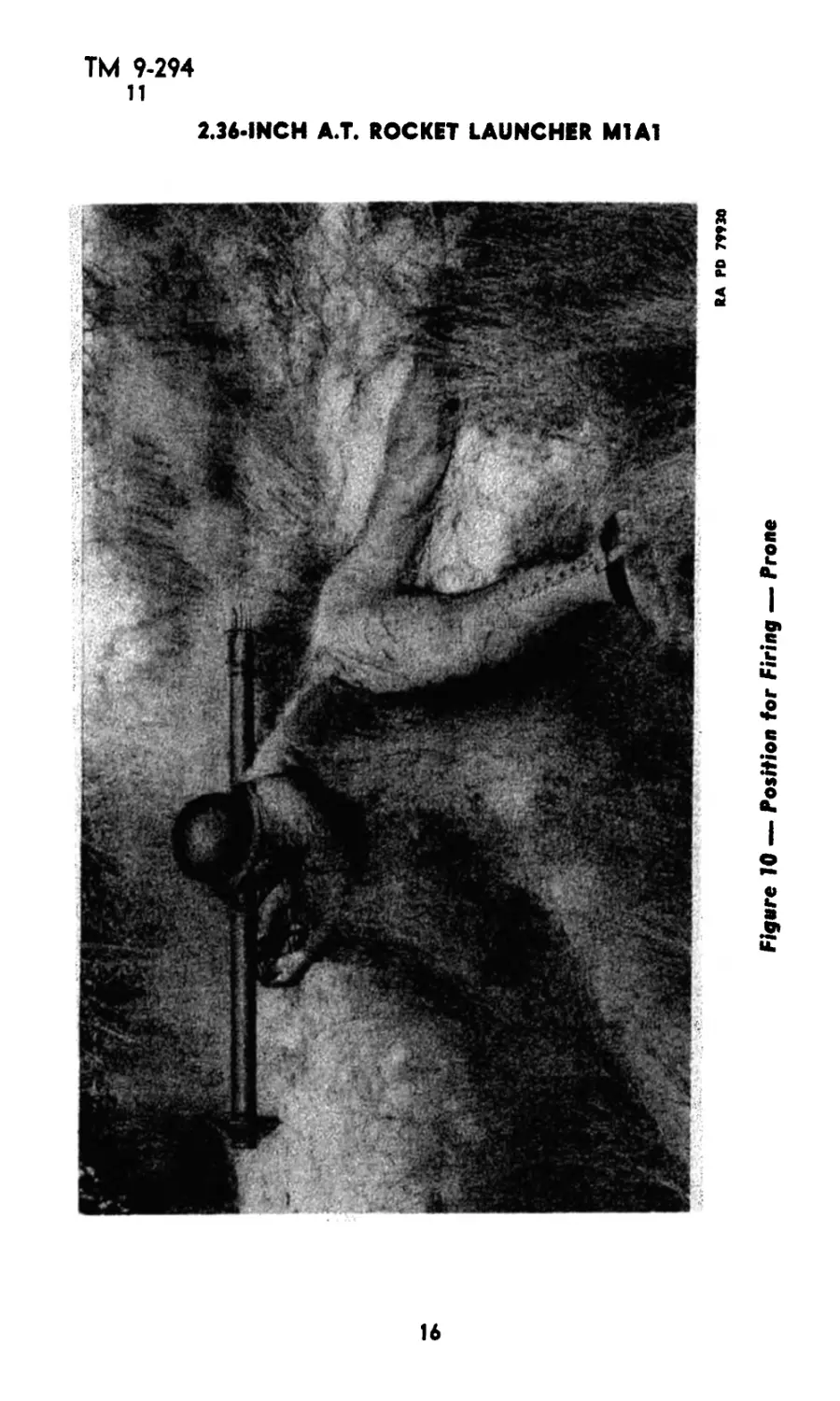
f. The launcher may be fired from the shoulder in the standing,
kneeling, sitting, or prone positions. If fired from the prone position,
the body should be at an angle of at least 45 degrees to the direction
of fire so as to avoid injury from the back blast of the rocket
g. In using the launcher, it is essential that no personnel, or in-
flammable material be directly behind the launcher within a distance
of 20 feet
h. Never stand in or near the rear of the launcher while it is being
fired because the hot gases can inflict serious burns. When firing from
trenches or fox holes, clearance should be provided so that back blast
is not deflected against personnel.
i. At temperatures below 14 F, the dry cells become too weak to
fire this weapon. When used at low temperatures, batteries should
be removed from the launcher and kept warm until just before firing.
Carrying the batteries in inner pockets in cold climates will keep
them sufficiently warm. The spare batteries can be carried in the
pockets and switched with the cold ones every half hour.
j. The rockets should not be fired at temperatures below zero F
nor above 120 F.
К
ТМ 9-294
5
2.36-INCH А.Т. ROCKET LAUNCHER M1A1
Section II
DESCRIPTION AND FUNCTIONING
Paragraph
Description.................................................. 5
Functioning.................................................. 6
5. DESCRII4 ION (figs. 1, 2, 11, 12, 13, and 14).
a. The launcher is essentially a long open barrel with a stock which
houses the electrical firing mechanism. The tube is approximately 54
inches long and has a smooth bore.
b. The launcher has a front and rear sight, both of which are
fixed to the barrel on the left side. The rear sight is of the peep type.
The front sight consists of three studs which are used for ranges of
100, 200, and 300 yards. Intermediate or greater ranges, lead, and
windage must be estimated by the firer.
c. Ahead of the front sight is assembled a flash deflector (fig. 3).
The deflector is a conical wire screen with a mounting clamp. It is
secured to the tube by the deflector screw and nut. When properly
assembled, the mounting clamp of the deflector overlaps the muzzle
end of the launcher. The function of the deflector is to deflect occa-
sional particles of unburned powder which might impinge upon the
fireris face.
d. The hand grip consists of the left and right trigger grips attached
to the trigger support. The trigger support accommodates the trigger
guard, trigger, and the lower and upper trigger switch contacts. The
trigger is pinned at its upper end to the trigger support and is free
to pivot. When the trigger is squeezed, it presses the bar contact
against the lower trigger switch contact to complete the electric cir-
cuit. When the pressure on the trigger is released, the trigger spring
forces the trigger to the forward position so as to break the electric
circuit.
e. The stock has a narrow vertical slot by means of which it slips
over the stock support to which it is attached by screws. In the bottom
of the stock there are two vertical cylindrical compartments for
accommodating four batteries. The two batteries in the rear compart-
ment are in actual use; the two batteries in the front compartment
are spares. On the left side of the stock is a small electric lamp for
testing the electric circuit and battery. The lamp is connected in
parallel with the firing mechanism and it lights when the trigger is
squeezed, regardless of whether a rocket is in the launcher or not.
A spare lamp is carried in a circular compartment on the right side
of the stock under the circuit indicator cover. The bottom of the
6
ТМ 9-294
5-6
DESCRIPTION AND FUNCTIONING
stock is fitted with a hasp assembly which keeps the batteries in posi-
tion and completes the electric circuit. The hasp assembly is kept
closed by a spring actuated hasp catch which engages the stock pin.
The battery spring contacts the batteries and is connected by wire
to the stock support to complete the electric circuit.
f. The face guard is on the barrel above the stock. The guard
serves to protect the firer’s face from the heat in the tube. The guard
is pressed on to the barrel and is held in position by its tension.
g. The portion of the barrel from the rear of the stock to the
insulated contact spring is wound with bracing wire. The contact
springs serve as connecting points for the contact wire leading from
the rocket. In this manner, the circuit is completed. At the rear of
the barrel is a spring actuated tail latch assembly. The function of
the latch is to engage notches on the tail of the rocket and hold it in
position for firing. The breech guard at the breech end of the barrel
facilitates loading of the rocket, protects the tail latch assembly, pre-
vents distortion of the end of the barrel, and prevents entry of dirt
and foreign material when the end of launcher rests on the ground.
h. When the 2.36-inch AT Rocket Launcher M1A1 is issued, it
is equipped with a battery designated as the Eveready 791-A, to
provide current for operating the firing mechanism. This battery con-
sists of two dry cell batteries of the Eveready No. BA-42 type, size
C, which are jointed together and placed in a cardboard container.
When replacement is necessary and a battery of the original type
cannot be supplied by ordnance personnel, two separate cells of the
battery BA-42 type will be used. These cells are a standard Signal
Corps item which are readily available in the field. Each is inch
in diameter and inches in over-all length.
6. FUNCTIONING.
a. When the trigger is squeezed, it forces the bar contact against
the lower trigger switch contact to complete the circuit
b. The passage of the electric current through the rocket sets off
an electric igniter in the rocket which in turn ignites the propelling
charge. Rearward escape of the powder gases through a jet forces
the rocket out of the barrel with a muzzle velocity of about 265 feet
per second. Propulsion of the rocket is by jet action of the propellent
powder and hence there is no recoil.
ТМ 9-294
7-9
2.36-INCH А.Т. ROCKET LAUNCHER Ml Al
Section III
OPERATION
Paragraph
Precaution ................................................. 7
Loading .................................................... 8
Sighting ................................................... 9
Firing .................................................... 10
Unloading.................................,................ 11
7. PRECAUTION.
a. During the operations of loading, sighting, and firing, the loader
should at no time stand directly behind the launcher.
b. See other precautions in paragraph 4.
8. LOADING.
a. The firer places the launcher on his right shoulder and aims at
the target The firer tests the circuit by squeezing the trigger several
times. The light bulb should light only when the trigger is squeezed.
b. The firer makes certain that the light is out and he must not
squeeze the trigger while the rocket is being loaded into the launcher.
c. The loader grasps the rocket by the tube and inserts the high-
explosive head into the launcher barrel, at the same time raising th
tail latch clear of the rocket (fig. 3).
d. Having inserted the head of the rocket into the launcher, the
loader then releases the tail latch and removes the safety pin from
the fuze.
e. The loader again raises the tail latch and carefully pushes the
rocket into the launcher until the tail latch engages a notch on the
tail fins.
f. The loader pulls the end of the contact wire of the fin (fig. 4),
pulls the wire straight back to uncoil it, and then engages the unin-
sulated portion of the wire in any of the coils of either of the contact
springs (fig. 5). The launcher is ready to be fired.
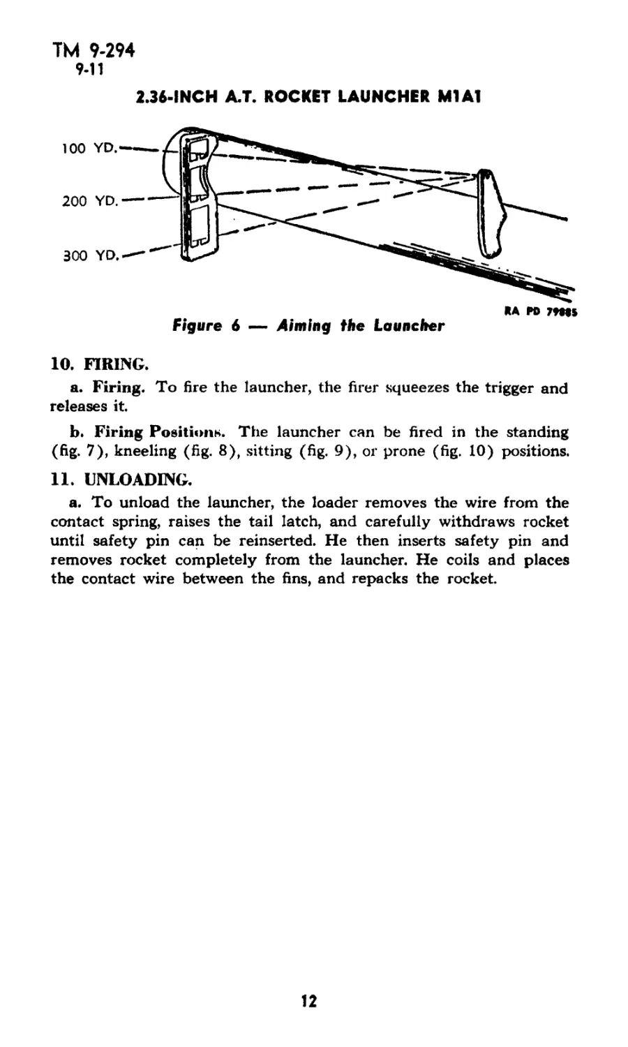
9. SIGHTING.
a. The firer estimates distances to target and picks proper stud
on front sight for aiming. He then sights at target through rear sight
by centering stud in peep of sight (fig. 6). The firer estimates inter-
mediate or greater ranges, lead, and windage.
8
ТМ 9-294
9
OPERATION
RA PD 77*27
Figure 3 — Loading Rocket Into Launcher
ТМ 9-294
9
2.36-INCH А.Т. ROCKET LAUNCHER M1A1
RA PD 7**34
Figure 4 — Pulling the Contact Wire Off the Fin
10
RA PD 79931
Figure 5 — Engaging Contact Wire in Contact Spring
OPERATION
ТМ 9-294
9-11
2.36-INCH А.Т. ROCKET LAUNCHER Ml Al
10. FIRING.
a. Firing. To fire the launcher, the firer squeezes the trigger and
releases it
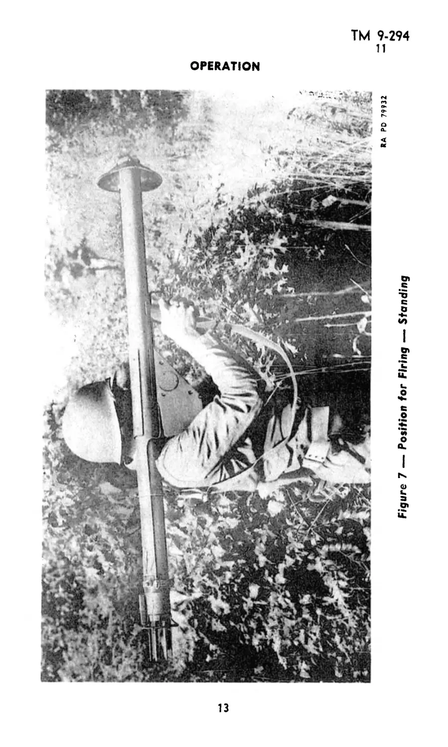
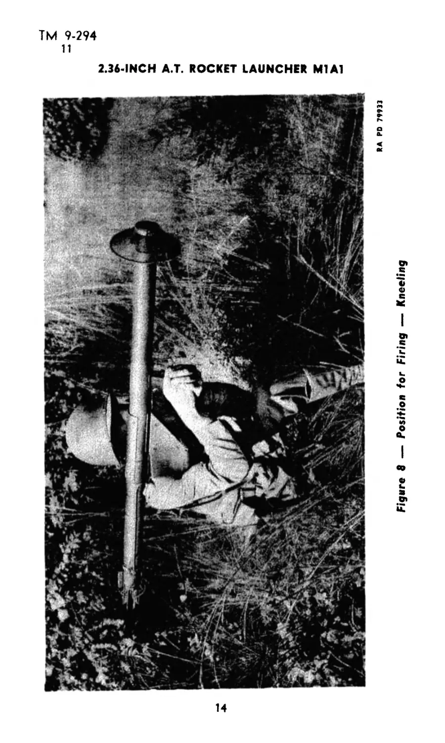
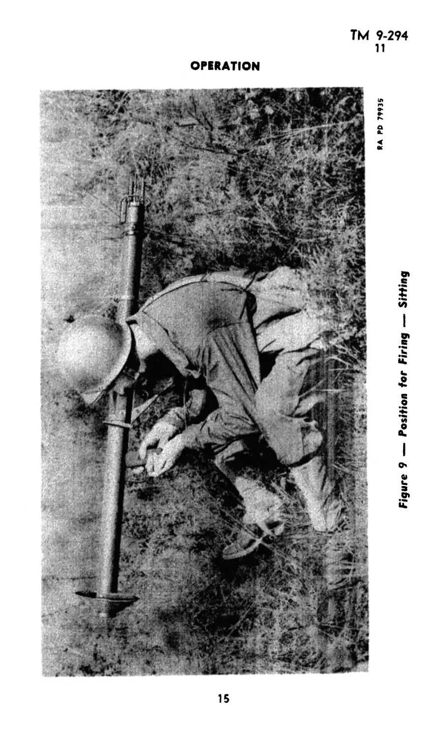
b. Firing Positions. The launcher can be fired in the standing
(fig. 7), kneeling (fig. 8), sitting (fig. 9), or prone (fig. 10) positions.
11. UNLOADING.
a. To unload the launcher, the loader removes the wire from the
contact spring, raises the tail latch, and carefully withdraws rocket
until safety pin can be reinserted. He then inserts safety pin and
removes rocket completely from the launcher. He coils and places
the contact wire between the fins, and repacks the rocket.
12
RA PD 79932
Figure 7 — Position for Firing — Standing
OPERATION
ТМ 9-294
11
2.36-INCH А.Т. ROCKET LAUNCHER Ml Al
14
RA PD 79935
Figure 9 — Position for Firing — Sitting
OPERATION
ТМ 9-294
11
2.36-INCH А.Т. ROCKET LAUNCHER Ml Al
Figure 10 —- Position for Firing — Prone
16
ТМ 9-294
12-14
Section IV
MALFUNCTIONS AND CORRECTIONS
Paragraph
General............................................. 12
Immediate action.................................... 13
Malfunctions and corrections........................ 14
12. GENERAL,
a. This section is intended to provide necessary instruction in the
related subjects of immediate action, and malfunctions and correc-
tions. These instructions should be studied by the firer and loader
before any firing is done.
13. IMMEDIATE ACTION.
a. Definition. Immediate action is the immediate and automatic
application of a remedy to fire the launcher if it malfunctions while
firing in actual or simulated combat. When a stoppage occurs during
firing, perform the immediate action described below.
b. Failure of Launcher to Fire. If the loaded launcher fails to
fire when the trigger is squeezed, proceed as follows:
(1) Squeeze the trigger again to fire the launcher.
(2) If the launcher still does not fire, then the loader cautiously
makes certain that the uninsulated portion of the contact wire en-
gages the contact spring. The firer then squeezes the trigger to fire
the launcher.
(3) If the launcher still does not fire, the loader waits 1 minute
and then removes wire from contact spring, raises tail latch, and care-
fully withdraws rocket until safety pin can be reinserted. He then
inserts safety pin and removes rocket completely from the launcher,
coils and places the contact wire between the fins, repacks the rocket,
and puts it aside for disposal by authorized personnel.
14. MALFUNCTIONS AND CORRECTIONS.
a. General. Proper care of the launcher before, during, and after
firing will eliminate most malfunctions.,Malfunctions which cannot be
remedied by immediate action should be dealt with in accordance
with instructions described in the following step:
(1) Failure to Fire.
(a) Failure to fire is generally caused by defective ammunition or
defective firing mechanism.
(b) If the contact wire is loosely connected to the rocket, the rocket
may be defective and should be turned over to ordnance maintenance
personnel.
(c) Defective firing mechanism may be due to spent or defective
batteries, loose connections, or broken parts.
17
ТМ 9-294
14
2.36- INCH А.Т. ROCKET LAUNCHER M1A1
1, Check the batteries by squeezing the trigger and observing
whether the bulb lights. If the bulb does not light, replace the bat-
teries and test again. If the bulb still does not light, change the bulb.
A spare bulb is carried under the circuit indicator cover, and may be
used if the bulb is broken or burnt out.
2. Remove the trigger grips and check the trigger switch contacts
for loose or broken parts. If the bar contact is deformed, bend it into
correct shape. If bar is broken, turn launcher over to ordnance main-
tenance personnel.
3. Check whether the battery spring contacts the batteries. If the
spring is broken, spread it out so that it will contact the batteries
(this should only be done in an emergency).
4. Remove the circuit indicator cover and check whether the wires
are loose.
5. Test by hand whether the wire is securely connected to the
stock contact. If the connection is broken, turn the launcher over to
ordnance maintenance personnel.
18
ТМ 9-294
15-16
Section V
CARE AND PRESERVATION
Paragraph
General............................................ 15
Cleaning and care of launcher...................... 16
15. GENERAL.
a. Proper functioning and accuracy of firing depend largely on
care and cleaning of the weapon. The weapon should be checked
daily for cleanliness, in garrison or camp, on the range, and in the
field. See that the bore is free of dust, dirt, mud, snow, or other foreign
material.
16. CLEANING AND CARE OF IAUNCHER.
a. Daily and Immediately After Firing. Wet a CLOTH, wiping,
with CLEANER, rifle bore, and run it through the barrel several
times. Then run a dry wiping cloth through until the inside of the
barrel is clean and dry. Saturate a clean dry wiping cloth with OIL,
lubricating, preservative, light, and then wring it out. Oil the bore by
running this cloth back and forth through the barret
b. Weekly. Apply one or two drops of OIL, lubricating, preserva-
tive, light, to the tail hinge pin.
c. Prior to Firing. Run a clean dry wiping cloth through the
barrel until, by the appearance of the cloth, it is indicated that the
film of oil has been removed from the bore.
d. External Parts of the Launcher. When necessary, clean the
rusted, pitted, and chipped exposed metal surfaces with CLOTH, cro-
cus, and repaint with ENAMEL, synthetic, olive-drab, lusterless. Do
not paint the contact springs or the flash deflector. To clean wooden
stock and grip, wipe with a clean wiping cloth lightly oiled with OIL,
linseed, raw, type A. Then wipe with a clean dry wiping cloth. Do not
use cloths which have been impregnated with raw linseed oil on
any other parts of the launcher.
e. If Used in Wet Weather. Disassemble the stock and trigger
grips and dry all electric contact points and wires with a dry cloth.
Clean and oil the rest of the launcher as described above.
19
ТМ 9-294
17-19
2.36-INCH А.Т. ROCKET LAUNCHER M1A1
Section VI
DISASSEMBLY AND ASSEMBLY
Paragraph
General................................................ 17
Disassembly ........................................... 18
Assembly.............................................. 19
17. GENERAL.
a. For ordinary care and cleaning it is not necessary to disassemble
the launcher except to remove the trigger grips. Further disassembly
is for the purpose of inspection, maintenance, and repair, and should
be performed under the supervision of a mechanic or ordnance per-
sonnel.
18. DISASSEMBLY (figs. 11, 12, and 13).
a. Flash Deflector. Unscrew the screw from the flash deflector
and remove the deflector, taking care not to lose the screw, nut, and
washer.
b. Sling. Disconnect the sling from the sling loops on the launcher.
c. Trigger. Unscrew the sling bracket screws and remove the
sling bracket. Unscrew the screws on the left trigger grip and remove
the trigger grips. Remove the cotter pin, withdraw the trigger pin,
and remove the trigger. Break the soldered connection between the
wire and the lower switch contact support Pry the conduit with the
wire loose from the clips on the left side of the stock support
d. Circuit Indicator Cover and Bulb. Unscrew the screws from
the circuit indicator cover. Remove the cover and break the soldered
wire connection. Remove the spare bulb and the socket assembly with
bulb.
e. Stock. Open the hasp on the under side of the stock and remove
the batteries. Remove the four screws from the hasp, and remove the
hasp. Break the soldered connection between the wire and the stock
support Slide the stock off the support
f. Tail Latch. Press down on tail latch body, remove cotter pin
and tail latch pivot pin, and carefully withdraw the tail latch spring.
g. Electrical System. The electrical system of the rocket launcher
is shown in figure 14.
19. ASSEMBLY.
a. Tail Latcb. Place tail latch spring in position over the stud
between tail latch shunt and tail latch body. Press down on tail latch
body and insert the tail latch pivot pin; secure it with the cotter pin.
20
ТМ 9-294
19
DISASSEMBLY AND ASSEMBLY
b. Soldered Connections. Solder the broken connections be-
tween the wire and lower switch contact, between the wire and stock
contact, and between the wire (on the battery spring) and the bottom
of the stock support.
e. Slock. Slide the stock partly onto the stock support. Keep the
wire between stock support and battery spring, moving in the slot
in the stock so as not to break the soldered connections. Replace the
conduit with 1 he wire in 1 he clips on the left side of the stock support.
Push stock into position on the stock support.
<1. Circuit Indicator <’over and Bulb. Assemble light bulb to
miniature socke t. Place unit in transverse hole in stock and secure
socket with two screws. Pull the socket wires out through the hole
in top of stock and solder to the wires leading from the conduits on
right side of stock support. Replace circuit indicator cover and secure
with the three screws. Attach the hasp spring to the hasp and assemble
the hasp to the stock, Replace the batteries in their compartments.
e. Trigger Grips and Sling. Attach the trigger grips to the trig-
ger support. Attach the sling bracket to the trigger grips and secure
the sling to the launcher.
f. Flash Deflector. Slide the flash deflector over the muzzle of
the barrel and secure in place by means of the nut, screw, and washer.
21
ТМ 9-294
19
2.36-INCH А.Т. ROCKET LAUNCHER M1A1
Figure J1 — Stock and drip Group — Farts
22
TM 9-294
19
DISASSEMBLY AND ASSEMBLY
A — SCREWS
В _ HASP
C —RIVET
D — HASP CATCH SPRING
E — HASP CATCH
F — BATTERY SPRING
G —WIRE
H —DRY CELL BATTERIES
j — STOCK
K — CONDUIT TUBE
L —SCREW
M — LIGHT BULB
N —- FACE GUARD
p —TRIGGER ASSEMBLY
Q —UPPER TRIGGER SWITCH CONTACT ASSEMBLY
R — LOWER TRIGGER SWITCH CONTACT ASSEMBLY
S — SCREW
T —LEFT TRIGGER GRIP
U — RIGHT TRIGGER GRIP
v —GRIP NUT
W —SCREW
X —SLING LOOP
Y —sling BRACKET
Z — SCREW
A A —STOCK NUT
BB—SCREW
CC —MINIATURE SOCKET
DD —CIRCUIT INDICATOR COVER
RA PO 79883A
Legend for Figure 11 — Stock and Grip Group — Parts
£
A—-STOCK SUPPORT F — SWITCH CONTACT LOWER SUPPORT RIVET
В — UPPER SWITCH CONTACT SUPPORT C — BAR CONTACT
C — SWITCH BASE H — SWITCH CONTACT BUTTON
D _ LOWER SWITCH CONTACT SUPPORT J — SWITCH CONTACT BAR
E — CRIP SUPPORT RA PD 7*884
2.36-INCH A.T. ROCKET LAUNCHER Ml Al
Figure 12 — Trigger Group
Figure 13 — Rear of Launcher
DISASSEMBLY AND ASSEMBLY
ТМ 9-294
19
2.36-INCH А.Т. ROCKET LAUNCHER M1A1
Figure 14 Лоске/ Laencher Showing Electrical System
26
ТМ 9-294
20-21
Section VII
AMMUNITION
Paragraph
Authorized rounds........................................ 20
Identification........................................... 21
Description ............................................. 22
Data .................................................... 23
Effect................................................... 24
Care and precautions in handling......................... 25
Packing.................................................. 26
Field report of accidents................................ 27
20. AUTHORIZED ROUNDS.
a. The ammunition currently authorized for use in Launcher,
rocket, A.T., 2.36", Ml Al, comprises the following rounds:
ROCKET, H.E., A.T., 236", M6A3; ROCKET, H.E., A.T., 236",
M6A1.
ROCKET, practice, 236", M7A3; ROCKET, practice, 236", M7A1.
21. IDENTIFICATION.
a. General. Ammunition is identified by the painting and mark-
ing on the item and all its packings. Complete identification of an
item of ammunition consists of:
(1) The standard nomenclature, which includes type, size, and
model designation.
(2) The ammunition lot number, which, in general, includes the
loader’s lot number, the loader’s symbol, and the date of loading.
b. Standard Nomenclature. Standard nomenclature is established
in order that each item issued by the Ordnance Department may be
specifically designated. Standard nomenclature for rockets is pub-
lished in Standard Nomenclature List No. S-9. The use of standard
nomenclature is mandatory for all purposes of record.
c. Model. When an item is adopted, it is assigned a model desig-
nation which consists of the letter “M” and an arabic numeral. If the
item is modified, this is shown by adding the letter “A” and the
appropriate numeral to the model designation.
d. Lot Number. The ammunition lot number is used to identify
a quantity of items manufactured under uniform conditions and which
is expected to function uniformly. The ammunition lot number is
required in all reference to specific items of ammunition in records
and reports.
e. Ammunition Identification Code. In order to facilitate requi-
sitions and records of ammunition in the field, each item of ammuni-
27
ТМ 9-294
21-22
2.36-INCH А.Т. ROCKET LAUNCHER M1A1
tion is assigned a five character code symbol. These symbols are listed
in Standard Nomenclature Lists and Ordnance Field Service Bulletin
No. 3-14.
f. Data Card. A 5- x 8-inch card, containing information con-
cerning the ammunition and its components, is sent with each ship-
ment of ammunition. When required, directions for assembly are
printed on the reverse of lhe card.
g. Earlier Models.
(1) Ammunition issued for the Launcher, rocket, A.T., 2.36", Ml,
was known as the M6 and M7 Rockets. The Ml Launcher is no
longer available and the M6 and M7 Rockets cannot be used in the
Launcher, rocket, A.T., 2.36", Ml Al.
(2) The M6 and M7 Rockets have a contact ring on the nose of
the rocket and a connecting wire, taped to the outside, running from
this ring to the tail. These are not present on the authorized rounds.
(3) The M6 and M7 Rockets have a cord tied to the safety pin
and tail closing plug; the authorized rounds have no such cord.
(4) The M6A3 and M7A3 Rockets have rounded nose and wheel-
shaped fin, while the M6A1 and M7A1 have pointed nose and fin
without rim.
22. DESCRIPTION.
a. General. The 2.36" rocket (fig. 15), consists of a head, a
stabilizer tube, and a finned tail. The head of the H.E., A.T. rocket
contains a high-explosive charge; the head of the practice rocket is
inert. The stabilizer tube is closed at the forward end by a plug,
containing the fuze, which screws into the head. A safety pin passes
through the plug and the fuze, and prevents the fuze from functioning
while it remains in place. The tail assembly attached to the rear
of the tube consists of a nozzle to which the fins are welded. The
stabilizer tube contains the propelling charge and an electric igniter.
The lead wires of the igniter pass through the nozzle; the short lead
is soldered to a fin, the long lead is stripped of insulation for approxi-
mately 6 inches from the end. The end is formed into a tab and is
lightly taped to another fin. This wire is known as the contact wire
(fig. 14). The nozzle is closed with a cardboard disk to protect the
propelling charge from dirt and moisture.
b. Painting and Marking. H.E., A.T. rockets are painted olive-
drab and marked in yellow with type, model, and lot number. Practice
rockets are painted black and marked in white.
c. Preparation for Firing. Rockets are prepared for firing by the
following steps:
(1) Unseal package and remove rocket from packing.
28
21.6" MAX. — BLACK, MARKING IN WHITE
21.6" MAX.— OLIVE DRAB, MARKING IN YELLOW -——------------------
AMMUNITION
RA PD 69102
Figure 15 — Rocket, H.E., A.T., 2.36", M6A1 (lower! and Rocket, Practice, A.T., 2.36", M7A1 (upper)
£
ТМ 9-294
22-24
2.36-INCH А.Т. ROCKET LAUNCHER Ml Al
(2) Insert head of rocket in launcher, remove safety pin from
tube, and complete insertion of rocket in launcher as described in
paragraph 8.
(3 ) By means of the tab formed on the end, pull the contact wire
from its taped attachment to the fin (fig. 15). Complete instructions
for loading are contained in paragraph 8.
NOTE: No attempt should be made to remove the short wire
which is soldered to the fin. Do not break or disconnect the contact
wire at the point where it enters the rocket.
23. DATA.
a. The 2.36" rockets are 21.6 inches long and weigh 3.5 pounds.
Fired from the launcher, they have a muzzle velocity of approximately
265 feet per second. Maximum range is 700 yards but limit of effec-
tive aimed fire is 300 yards.
b. Since the effect of the H.E., A.T. rocket is produced entirely by
the high order explosion of the head, the rocket will produce the
same effect regardless of its velocity at impact, provided the impact
is sufficient to operate the fuze. After the safety pin has been removed,
a blow, equivalent to dropping the rocket on its nose on normal soil,
will operate the fuze and detonate the rocket. Light impacts insuffi-
cient to detonate the fuze, will increase its sensitivity so that the
fuze will detonate on receiving a lighter impact than ordinarily neces-
sary for functioning,
c. The propelling charge normally burns in 0.02 to 0.03 second,
that is, burning is complete before the rocket leaves the launcher.
24. EFFECT.
a. ROCKET, H.E., A.T., 2.36", M6A1, has effect against various
targets as follows:
(1) Armor Plate. Penetration of armor found on most tanks
may be expected at all ranges. A hole is blown through the armor and
heated particles of metal are sprayed through in a cone shaped pat-
tern. Any ammunition within this pattern is usually exploded.
(2) Masonry. Penetration of brick and masonry from several
inches to a foot or more, depending on quality of structure, may be
expected.
(3) Structural Steel. Produces shattering effect against cast
steels and such materials as girders and railroad rails. Produces
extensive damage, probably irreparable, to motor blocks.
(4) Wood. Penetration of timber from several inches to a foot
or more, depending on the timber, may be expected.
(5) Soil. Impact with ground at ranges below 300 yards will
ordinarily result in a ricochet rathfer than a detonation. At ranges in
30
ТМ 9-294
24-27
AMMUNITION
excess of 300 yards, the angle of impact is steep enough to cause a
detonation which resembles that of a 75-mm high-explosive shelL
However, impact on a very soft material such as mud, soft sand, or
water will not cause detonation of the rocket.
25. CARE AND PRECAUTIONS IN HANDLING.
a. Ammunition is packed to withstand all conditions ordinarily
encountered; however, the following should be observed:
(1) Boxes containing ammunition should not be dropped, thrown,
tumbled, or dragged.
(2) The waterproof sealing of ammunition containers should not
be broken until the ammunition is about to be used. Items unpacked
but not used should be restored to their original condition and pack-
ings and resealed.
h. Rockets should be protected against moisture and extremes
of temperature. They should not be stored where temperatures exceed
120 F and should not be exposed to the direct rays of the sun.
c. In firing rockets, consideration should be given to the blast of
flame to the rear. The loader should exercise particular care to stand
clear of the blast,
d. Rockets prepared for firing and not fired will have the safety
pin replaced and will be returned to the original container which
will be resealed.
e. If a rocket fails to fire and examination shows the launcher is
not at fault, the safety pin will be replaced and the rocket set aside
for destruction by authorized personnel.
f. Rockets must not be disassembled.
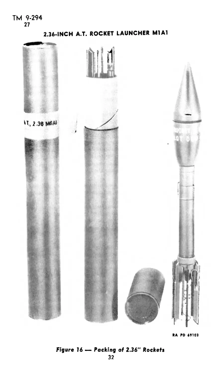
26. PACKING.
a. The 2.36" rocket is packed (fig. 16) one per fiber container.
Each fiber container is sealed with a strip of adhesive tape (yellow
for H.E., A.T., M6A1, and blue for practice Rockets M7A1), printed
with the type and model of the rocket. Twenty such containers are
packed to the wooden box, 1.55 x 1,13 x 2.08 feet. As packed, the box
weighs approximately 128 pounds.
27. FIELD REPORT OF ACCIDENTS.
a. When an accident involving the use of ammunition occurs dur-
ing training practice, the procedure prescribed in section VII, AR
750-10, will be observed by the ordnance officer under whose super-
vision the ammunition is maintained or issued. Where practicable,
reports covering malfunctions of ammunition in combat will be made
to the Chief of Ordnance, giving the type of malfunction, type of
ammunition, the lot number of the complete rounds or separate-
loading components, and condition under which fired.
31
ТМ 9-294
27
2.36-INCH А.Т. ROCKET LAUNCHER M1A1
RA PD 49103
Figure 16 — Packing of 2.36" Rockets
32
TH 9-294
28-29
Section VIII
INSPECTION
Paragraph
Purpose................................................. 28
Procedure............................................. 29
28. PURPOSE.
a. Inspection of your materiel is vital. Thorough systematic inspec-
tion at regular intervals is the best insurance against an unexpected
breakdown at the critical moment when performance is absolutely
necessary. Never let your materiel run down; keep it in first class
fighting condition by vigilant inspection and prompt maintenance.
b. Inspection is for the purposes of determining the condition of
the materiel and the repairs or adjustments necessary to insure ser-
viceability and proper functioning. Its immediate aim is preventive
maintenance which includes inspection for any damage caused by
improper handling before delivery into your hands and inspection for
ordinary wear so as to prevent malfunctioning. It also pertains to
correction of defects that may later require replacement of parts.
29. PROCEDURE (figs. 11, 12, and 13).
a. Inspect the launcher for general condition, loose or broken com-
ponents, painting defects, bends, dents, or for obstructions in the bore.
b. Test the electric circuit by squeezing the trigger several times.
The bulb should light when the trigger is squeezed. If the bulb does
not light, check the batteries and bulb and replace the defective items.
c. Check for any loose wire connections.
d. Remove the trigger grips and check for the following:
(1) Deformed or broken switch contact bar.
(2) Missing switch contact button.
(3) Missing bar contact.
(4) Missing switch contact lower support rivet.
(5) Loose connections, particularly between bar contact and upper
switch contact support, and between wire and upper and lower switch
contact supports.
(6) Corroded electric contact points.
e. Remove the circuit indicator cover and check for loose wire
connection. Remove the hasp and check for loose connection between
wire and stock support.
f. Remove the batteries and examine for condition. Replace them
if they are cracked, swollen, broken, or do not light the bulb.
g. Check functioning of tail latch and of trigger spring.
h. Examine the barrel of the launcher for rust, scale, and dents.
i. Examine the contact springs to see that they are secure to
the clamp and that they are clean and free from rust, paint, and
grease.
33
ТМ 9-294
30-31
2.36-INCH А.Т. ROCKET LAUNCHER Ml Al
Section IX
MAINTENANCE AND REPAIR
Paragraph
Preventive maintenance ................................. 30
Repairs................................................. 31
30. PREVENTIVE MAINTENANCE (figs. 11, 12, and 13).
a. These instructions may be carried out by the using arms.
b. Tighten all screws and nuts to prevent their becoming loose in
service. This should be done periodically when the weapon is in
service. Clean all rust and pitted surfaces with CLOTH, crocus, and
repaint with ENAMEL, synthetic, olive-drab, lusterless.
31. REPAIRS.
a. The following operations must be performed by a company
mechanic or ordnance maintenance personnel.
b. Solder all loose or broken soldered connections.
c. Replace any defective bulbs.
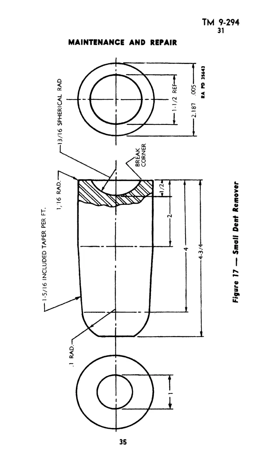
d. Remove dents in the barrel by using the tools shown in figures
17 and 18. These tools should be improvised by the ordnance ma-
chinist,
(1) Drive the small dent remover (fig. 17) through the barrel.
This will increase the diameter of the dented part of the barrel up
to 2.187 inches.
(2) Drive the large dent remover (fig. 18) through the barrel.
This will bring the diameter of the dented part of the barrel back
to the original 2.369 inches.
(3) To restore the original round contour of the barrel, force the
dent remover in place under the dents. Using the dent remover as an
anvil, hammer the outside surface of the barrel with a ball-peen
hammer.
e. Replace the trigger assembly if the trigger spring is too weak
or if trigger stop is missing.
f. If tail latch does not function, replace the tail latch spring.
g. Replace the trigger grips if broken or cracked so that moisture
cannot get in.
h. If the bar contact is deformed, it may be bent to its proper
shape to enable firing of the launcher. This should be replaced as
soon as practicable.
L If electrical contact points are corroded, clean with CLOTH,
crocus.
34
<л
Figure 17 — Small Dent Remover
MAINTENANCE AND REPAIR
4-3/4'
RA PD 35642
2.36-INCH A.T. ROCKET LAUNCHER Ml Al
Figure 18 — Large Dent Remover
ТМ 9-294
32-34
Section X
OPERATION UNDER UNUSUAL CONDITIONS
Paragraph
General............................................... 32
Arctic climates.........., . ........................ 33
Tropical climates..................................... 34
32. GENERAL.
a. When operating under unusual conditions such as tropical or
arctic climates, severe dust or sand conditions, and near salt water,
it is essential that all the precautions listed below should be observed.
33. ARCTIC CLIMATES.
a. In temperatures below freezing, and particularly in arctic cli-
mates, all operating parts should be kept absolutely free of moisture.
The bore of the launcher should be cleaned daily and oiled as
described in paragraph 16. The batteries should be removed from
the launcher and kept warm until just before firing. Carrying the
batteries in inner pockets will keep them sufficiently warm. Imme-
diately upon bringing indoors, the launcher should be cleaned on the
outside and inside with a dry clean cloth. Remove the grips and
clean and dry the contacts. After it has reached room temperature,
clean and dry the launcher again, and oil the bore. Rockets should
not be fired at temperatures below zero F.
34. TROPICAL CLIMATES.
a. Tropical Climates. In tropical climates where temperature and
humidity are high, or where salt air is present, and during rainy
seasons, the launcher should be thoroughly inspected and cleaned
daily. The bore should be oiled a little more liberally than prescribed
in paragraph 16. Wood parts should be inspected to see that swelling
due to moisture does not bind working parts. If this does occur,
shave off only enough wood to relieve binding. A light coat of OIL,
linseed, raw, type A applied at least every month and well rubbed
in with the heel of the hand, will help to keep moisture out Allow
oil to soak in for a few hours and then, wipe and polish the wood
with a dry clean wiping cloth. Do not fire rockets at temperatures
above 120 F.
NOTE: Care should be taken to see that linseed oil does not get
onto electric contacts as it will gum when dry.
b. Hot Dry Climates. In hot dry climates, where sand and dust
are apt to get into the bore, the launcher including the bore should be
wiped clean daily or more often if necessary. Oiling of the bore should
be done very sparingly and only in the event that atmospheric con-
ditions cause rusting of the bore surface. In such climates, wood
37
ТМ 9-294
34
2.36-INCH А.Т. ROCKET LAUNCHER Ml Al
parts are apt to dry out and shrink, and a more frequent application
of OIL, linseed, raw, type A, will help keep wood in condition. During
sand or dust storms the breech and muzzle should be kept covered.
Do not fire rockets at temperatures above 120 F.
38
ТМ 9-294
35-37
Section XI
PAINTING
Paragraph
General................................................ 35
Preparation of surfaces for painting................... 36
Painting metal surfaces.............................- . 37
Preservation of outside painted surfaces............... 38
Removal of paint....................................... 39
<35. GENERAL.
a. Ordnance materiel is painted before issue to the using arms,
and one maintenance coat per year will ordinarily be ample for
protection. With but few exceptions, this materiel will be painted
with ENAMEL, synthetic, olive-drab, lusterless. The enamel may be
applied over old coats of long oil enamel and oil paint previously
issued by the Ordnance Department if the old coat is in satisfactory
condition for repainting.
b. Paints and enamels are usually issued ready for use and are
applied by brush or spray. They may be brushed on satisfactorily when
used unthinned in the original package consistency, or when thinned
no more than 5 percent by volume with THINNER, for synthetic
enamels. The enamel will spray satisfactorily when thinned with
15 percent by volume of thinner. Linseed oil must not be used as a
thinner since it will impart a luster not desired in this enamel. If
sprayed, it dries hard enough for repainting within У2 hour and
dries hard in 16 hours.
c. Complete information on painting is contained in TM 9-850.
(I. All external metal surfaces of the launcher must be protected
with paint except the contact springs and the flash deflector.
36. PREPARATION OF SURFACES FOR PAINTING.
a. If the base coat on the materiel is in poor condition, it is more
desirable to strip the old paint from the surface than to use sanding
and touch-up methods. After stripping, it will be necessary to apply
a primer coat.
b. PRIMER, synthetic, rust-inhibiting, for bare metal, should be
used on metal as a base coat.
<♦ . The effectiveness of a painting job depends partly on the selec-
tion of a suitable paint, but largely upon the care used in preparing
the surface prior to painting. All parts to be painted should be free
of all extraneous matter such as rust, dirt, and grease, and must be dry.
37. PAINTING METAL SURFACES.
a. Metal parts in need of cleaning should be washed with a liquid
solution consisting of V2 pound of SODA ASH in 8 quarts of warm
39
ТМ 9-294
37-39
2.36-INCH А.Т. ROCKET LAUNCHER M1A1
water. If SODA ASH is not available, use warm soap solution, or
W£irm water alone. Then rinse with clear water and wipe thoroughly
dry. If the materiel is in fair condition and marred only in spots, these
spots should be ( leaned and then touched up with ENAMEL, syn-
thetic, olive drab, lustcrless, and permitted to dry. The whole surface
should then be sandpapered with PAPER, hint, class B, No. 1, and a
finish coat of ENAMEL, synthetic, olive-drab, lusterless, applied and
allowed to diy thoroughly hefcir the materiel is used. If the equip
ment is in bad condition, all parts should be thoroughly sanded with
PAPER, flint, class B, No. 2, given a coat of PRIMER, synthetic,
refinishing, and permitted to dry for at least 16 hours. They should
then be sandpapered with PAPER, flint, ( lass B, No. 0(1, wiped free
from dust and dirt, and given a final coat of ENAMEL, synthetic,
olive-drab, lusterless, and allowed to dry thoroughly before the
materiel is used.
38. PRESERVATION OF OUTSIDE PAINTED SURFAC ES.
a. Continued friction or rubbing must be avoided, as it will smooth
the surface and produce a gloss. The materiel should not be washed
more than once a week. Care should be taken to see that the washing
is done entirely with a sponge or a wiping cloth. The surface should
never be rubbed or wiped, except while wet, or a gloss will develop.
h. It is not desirable that materiel painted with lusterless enamel
be kept as clean as that covered with glossy paint. A small amount
of dust increases the camouflage value. Grease spots should be re-
moved with SOLVENT, dry-cleaning. Whatever portion of the spot
that cannot be so removed should be allowed to remain.
<•. Continued friction of wax-treated tarpaulins on the materiel
will also produce a gloss, which should be removed with SOLVENT,
dry-cleaning.
<1. Tests indicate that repainting with ENAMEL, synthetic, olive-
drab, lusterless, is necessary once a year, and restenciling with
ENAMEL, synthetic, stenciling, lusterless, blue-drab, twice a year.
39. REMOVAL OF PAINT.
a. After repeated paintings, the paint may crack and scale off in
places, presenting an unsightly appearance. If such is the case, remove
the old paint with REMOVER, paint and varnish. See TM 9-850
for details. It is important that every trace of paint remover be com-
pletely removed with SOLVENT, dry-cleaning, and that the equip-
ment be perfectly dry before repainting is attempted. The surfaces
thus prepared should be painted according to directions in para-
graph 36.
40
ТМ 9-294
40
Section XII
STORAGE AND SHIPMENT
Paragraph
Preparation of 2.36-inch AT rocket launcher M1A1 prior to
shipment................................................ 40
Storage .................................................. 41
40. PREPARATION OF 2.36-INCH AT ROCKET LAUNCHER
M1A1 PRIOR TO SHIPMENT.
a. Lubrication. Lubrication of the 2.36-inch AT Rocket Launcher
M1A1 shall be performed as directed in paragraph 16.
b. Painting.
(1) Removing Rust Spots. All painted surfaces that have be-
come checked, pitted, or rusted, shall be thoroughly cleaned with
CLOTH, crocus, removing all rust spots. (All external metal surfaces
must have a coating of paint, except the contact springs and the flash
deflectors. These parts must be completely waterproofed.)
(2) Application of PRIMER, Synthetic, Rust-inhibiting.
Apply a liberal coating of PRIMER, synthetic, rust-inhibiting over
entire area of the cleaned surface to be repainted as follows:
(a) Brushing or Spraying. PRIMER, synthetic, rust-inhibiting,
should be used on bare metal as a base coat for synthetic enamel.
It may be applied either by brushing or spraying. The primer will
brush satisfactorily as received or after the addition of not more
than 5 percent by volume of the proper thinner. For spraying, the
primer may be thinned with not more than 15 percent by volume of
thinner. Allow to dry thoroughly.
(3) Sandpapering Surfaces. Sandpaper the primed surfaces
with PAPER, flint, class B, grade No. 00, and wipe all particles of
dust from surfaces.
(4) Application of Enamel. Apply coat of ENAMEL, synthetic,
olive-drab, lusterless, and allow to dry thoroughly before the materiel
is used.
c. Cleaning. The bore of the 2.36-inch AT Rocket Launcher
M1A1 shall be thoroughly cleaned with SOLVENT, dry-cleaning, or
with a soap solution as follows:
41
TH 9-294
40
2.36- INCH A.T. ROCKET LAUNCHER Ml Al
(1) Apply SOLVENT, dry-cleaning, to clean cloth attached to
a ram rod anti swab thoroughly. Repeat this operation until all traces
of dirt, grease, and foreign matter have been removed. Dry thoroughly
using ( lean c loths.
(2) Apply soap solution by vigorously swabbing the bore until all
traces of contamination have* been removed. The bore shall then be
rinsed with clean, hot water, and dried thoroughly.
(3) Avoid contact of bare hands with the cleaned surfaces.
d. Preservation of Materiel. Application of preservative shall be
performed immediately after cleaning.
(1) Using a ram rod and clean cloths soaked in OIL, lubricating,
preservative, medium, swab the bore of the launcher thoroughly using
a generous quantity of the preservative.
(2) Repeat operation until all interior surfaces of the* bore are
thoroughly covered with a protective coating of the* preservative.
(3) Apply OIL, lubricating, preservative, medium, to contact
springs and flash deflectors.
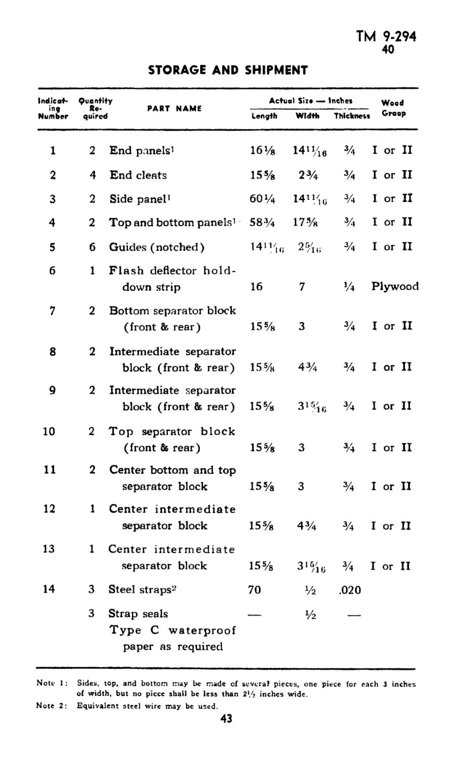
e. Boxing of Materiel (figs. 19 and 20).
(1) Bill of Material. The following is a bill of material re-
quired to construct one complete nailed wood shipping box, style 4,
for six 2.36-inch AT Rocket Launchers M1A1 including slings and
flash deflectors referred to in illustrations, figures 19 and 20.
(a) Data.
Indicating numbers Type of container Gross weight (lb) Dimensions (in.) Length Width Depth Displacement (cu ft) those referred to in illustrations (figs. 19 and 20) Style 4 nailed wood box 155 Inside Outside 57 »/« 601/4 16У8 17% 14iyle 16%fi 10
42
ТМ 9-294
40
STORAGE AND SHIPMENT
Indicat- ing Number Quant! Re* quire ♦y PART NAME d Actual Size —• Inches Wood Group
Length Width Thickneu
1 2 End panels1 16% 14"/ie % I or II
2 4 End cleats 15% 2% % I or II
3 2 Side panel1 60% 14”/i« % I or II
4 2 Top and bottom panels1 58% 17% % I or II
5 6 Guides (notched) 14'V1(i 2/н; % I or II
6 1 Flash deflector hold- down strip 16 7 % Plywood
7 2 Bottom separator block (front & rear) 15% 3 % I or II
8 2 Intermediate separator block (front & rear) 15% 4% % I or II
9 2 Intermediate separator block (front & rear) 15% 3%ie % I or II
10 2 Top separator block (front & rear) 15% 3 % I or II
11 2 Center bottom and top separator block 15% 3 % I or II
12 1 Center intermediate separator block 15% 4% % I or II
13 1 Center intermediate separator block 15% % I or II
14 3 Steel straps2 70 Уг .020
3 Strap seals Type C waterproof paper as required — Уг —
Note 1: Sides, top, and bottom may be made of several pieces, one piece for each 3 inches
of width, but no piece shall be less than 2l/j inches wide.
Note 2: Equivalent steel wire may be used.
43
ТМ 9-294
40
2.36-INCH А.Т. ROCKET LAUNCHER Ml Al
GREASEPROOF WATERPROOF PAPER
AND CLEATS (STAGGER)
Figure 19 Packing Box for Six Launchers, Rocket, AT,
Ml Al, w/Slings and Flash Deflectors
ЛЛ
ТМ 9-294
40
STORAGE AND SHIPMENT
NOTE • NUMBERS IN CIRCLES
CORRESPOND WITH NUMBERS
AS USTED IN SILL OP MATERIAL
NOTE ALL DIMENSIONS INDICATED ON THIS ILLUSTRATION ARE IN INCHES. RA PD 80Э60
Figure 20 — Packing Box for Six Launchers, Racket, AT,
Ml Ah Showing Details of Blocking
45
ТМ 9-294
40-41
2.36-INCH А.Т. ROCKET LAUNCHER Ml Al
(2) Packing Procedure (figs. 19 and 20).
(a) Wrap launchers at both ends with greaseproof-waterproof
paper and securely bind with TAPE, adhesive, nonhygroscopic.
(b) Wrap each flash deflector with greaseproof-waterproof paper
and telescope six wrapped deflectors together.
(c) Cushioning material, such as paper or felt padding, shall be
wrapped around launchers where contact is made with blocking in
order to prevent chafing of paint.
(d) Entire inside of box shall be lined with an approved type C
waterproof paper as specified in U. S. Army Specification No. 100-
14A and the edges shall be coated with asphaltum.
(e) Place two blocks (7) and block (11) in guides (5) and slide
to bottom of box with cut-outs facing up.
(i) Place two launchers (in opposite .directions) on blocks (7)
and (11) with the conduit tube facing up. Make sure that cushioning
material is separating blocks from launchers.
(i) Place two blocks (8) over launchers with the notched groove
of one side of block directly over the conduit tube. Place block (12)
in position.
(h) Place six flash deflectors in position on bottom of box with
hold-down strip (6) covering flash deflectors as shown in figure 20.
(i) Repeat above operations until box is packed assembling blocks
as indicated in figure 20, making sure that three launchers are all in
one direction and the other three are in the opposite direction with
the conduit tubing facing up.
41. STORAGE.
a. The launcher should be prepared and packed in the same man-
ner as described in paragraph 40 before being stored.
46
TH 9-294
42-43
Section XIII
REFERENCES
РагафгарЬ
Standard nomenclature lists.............................. 42
Explanatory publications................................. 43
42. STANDARD NOMENCLATURE LISTS.
a. Cleaning, preserving and lubricating materials; re-
coil fluids, special oils, and miscellaneous related
items........................................... SNL K-l
b. Launcher, rocket, A.T. 2.36-in. Ml and Ml Al... . SNL B-36
c. Rockets, all types and components............. SNL S-9
d. Soldering, brazing and welding material, gases and
related items................................... SNL K-2
e. Tools, maintenance, for repair of small and hand
arms, and pyrotechnic projectors................ SNL B-20
f. Truck, small arms repair, Ml.................. SNL G-72
g. Truck, 21/2-ton, 6x6, small arms repair, M7 and
M7A1........................................ SNL G-138
Current Standard Nomenclature Lists are as tabulated
here. An up-to-date list of SNL*s is maintained as the
“Ordnance Publications for Supply Index,*’ now pub-
lished in ......................................... OFSB 1-1
43. EXPLANATORY PUBLICATIONS.
a. Ammunition.
Ammunition, general................................ TM 9-1900
Ammunition identification code..................... OFSB 3-14
Range regulations for firing ammunition for training and
target practice ................................... AR 750-10
b. Maintenance.
Chemical decontamination materials and equipment. . . TM 3-220
Cleaning, preserving, lubricating, and welding materials
and similar items of issue by the Ordnance Depart-
ment ................. .......................... TM 9-850
Defense against chemical attack. .................. FM 21-40
Inspection of ordnance materiel.................... TM 9-1100
c. Ordnance Storage and Shipment.
Instructions and specifications for packaging ordnance
general supplies................................... IOSSC-(a)
Instructions for marking shipments of ordnance supplies IOSSC-(b)
Ordnance storage and shipment chart — group В —
major items........................................ OSSC-B
47
ТМ 9-294
2.36-INCH А.Т. ROCKET LAUNCHER M1A1
INDEX
Page No.
Ammunition
authorized rounds .............. 27
care and precautions in handling 31
data ........................... 30
description ................. 28-30
effect ...................... 30-31
field report of accidents...... 31
identification .............. 27-28
packing ........................ 31
Arctic climates, care of launcher in 37
Assembly of launcher............ 20-21
Authorized rounds of ammunition 27
в
Boxing materiel for shipment.. 42-46
Page No.
Flash deflector
assembly ......................... 21
disassembly ...................... 20
Functioning of launcher.............. 7
I
Identification of ammunition... 27—28
Inspection of launcher ............. 33
c
Care and preservation
ammunition ..................... 31
launcher ...................... 19
Characteristics of rocket launcher 3
Circuit indicator cover and bulb
assembly ....................... 21
disassembly .................... 20
Cleaning bore of rocket launcher 41-42
D
Data
ammunition ................... 30
rocket launcher ............... 3
Description
ammunition .................. 28-30
launcher ..................... 6-7
Dimensions of boxing material... 43
Disassembly of launcher......... 20
E
Electrical system of rocket launcher 20
F
Field report of ammunition acci-
dents ........................... 31
Firing the launcher.............. 12
Launcher, rocket, A.T., 2.36-in.,
M1A1
care and preservation ............ 19
description ................... 6-7
functioning ..................... 7
inspection ................ . . 33
maintenance and repair ......... 34
malfunctions and corrections. 17—18
operation......................8-12
M
Maintenance and repair of launcher 34
Malfunctions and corrections. . 17-18
Metal surfaces, painting......39-40
Operation
firing ..........................» 12
loading . . ...................... 8
precautions ...................... 8
sighting ......................... 8
under unusual conditions
arctic climates ............... 37
tropical climates ......... 37-38
unloading ....................... 12
Packing ammunition.............. 31
Paint <-ing)
ammunition ................... 28
metal surfaces ............ 39-40
preparation for............... 39
L
о
p
48
ТМ 9-294
INDEX
Р—Cotlt'd Peg* No.
Paint (-ing)—Cont’d
preservation of outside painted
surfaces .................... 40
removal ..................... 40
Precautions
care of launcher ............. 3-5
operation of launcher......... 8
Peg* No.
Storage and shipment
preparation prior to shipment 41-46
storage ........................... 46
s
Stock
assembly ...................... 21
disassembly ................... 20
T
Tail latch, assembly and dis-
assembly ....................... 20
Trigger grips and sling
assembly ........................ 21
disassembly .................. 20
Tropical climates, care of launcher
in .......................... 37-38
A.G. 300.7 (2 Sep 43)
O.O. 471.94/902 (R) (19 Jul 43)
By order of the Secretary of War:
G. C. MARSHALL,
Chief of Staff»
Official:
J. A. ULIO,
Major General,
The Adjutant General.
Distribution: R 9(4); Bn 9(2); IBn and L 3 and 11(2); C 9(5);
C and H 2, 4, 5, 6, 7, 10, 17 and 18(2)
(For explanation of symbols, see FM 21-6.)
RAPD13OCT43-232M 49
PUBLICATIONS DIVISION, RARITAN ARSENAL.
NOTES
NOTES