/


Tags: weapons
Year: 1945


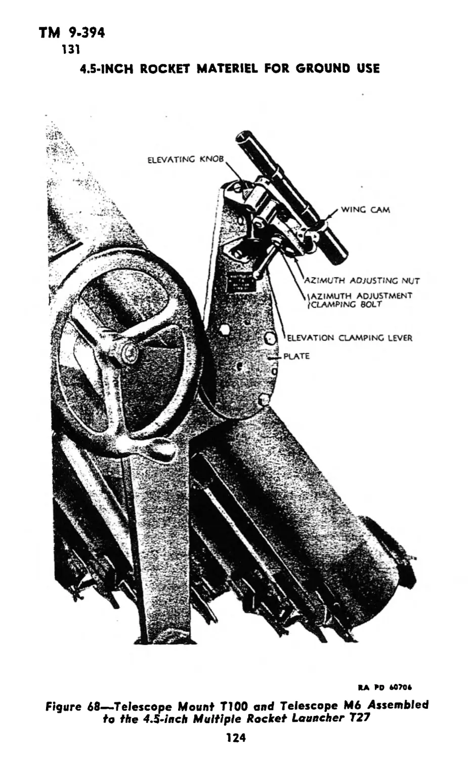
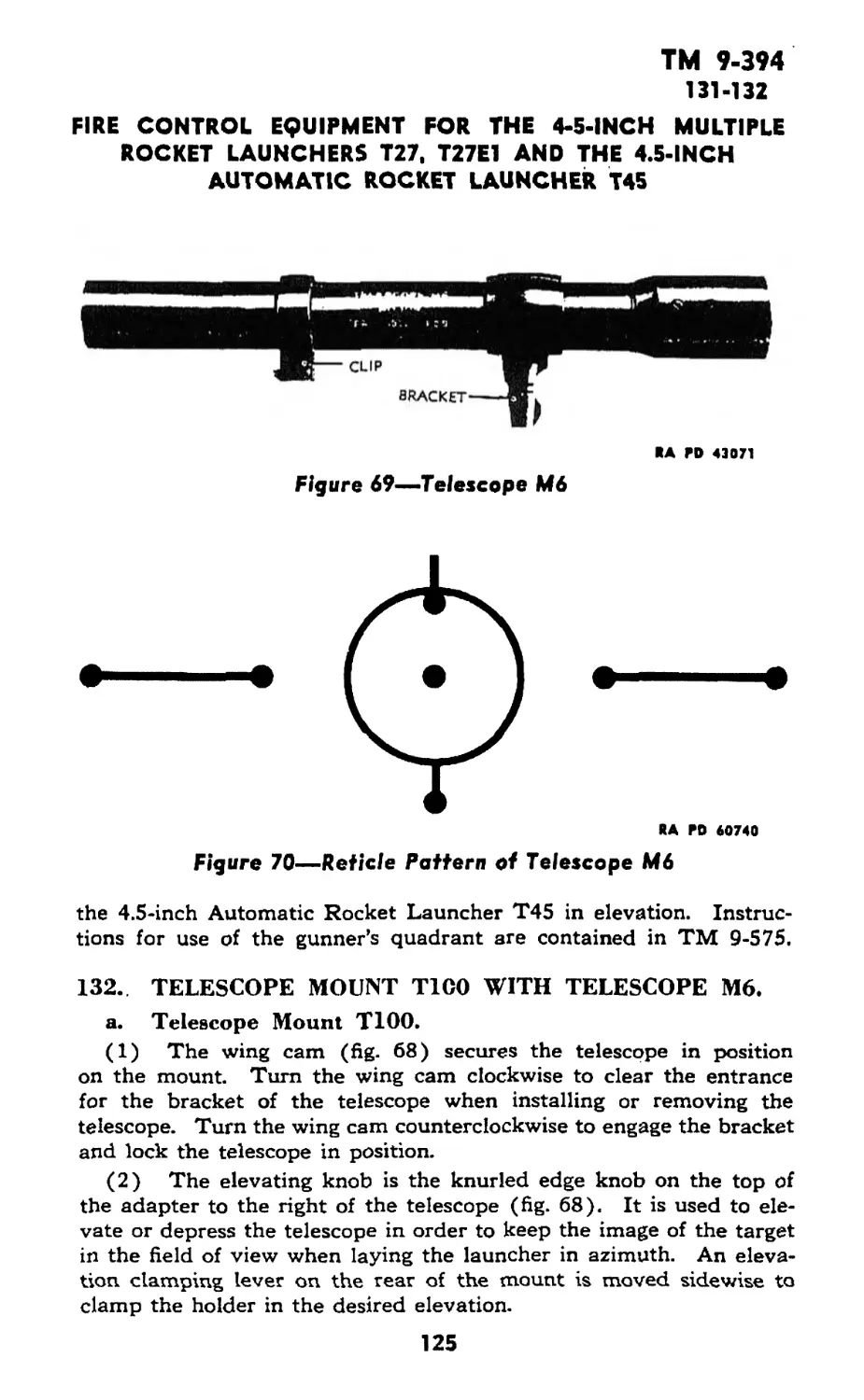
Text
WAR DEPARTMENT TECHNICAL MANUAL
TM 9-394
This TM supersedes WDTB 9-393-1, dated IS May 44; WDTB 9-394-1, dated 2 Feb 45; and
WDTB ORD 121. dated 12 Jul 44. This TM supersedes portions of WDTB ORD 236, dated 21
Dec 44, which apply to the materiel covered in this TM; however, this ТВ remains in force
until incorporated in other affected TM’s or specifically rescinded.
4.5-INCH
ROCKET MATERIEL
FOR GROUND USE
WAR DEPARTMENT • 7 FEBRUARY 1945
RESTRICTED, dissemination of restricted matter.
No person is entitled solely by virtue of his grade or position to knowledge
or possession of classified matter. Such matter is entrusted only to those
individuals whose official duties require such knowledge or possession.
(See also paragraph 23b, AR 380-5, 15 March 1944.)
WAR DEPARTMENT
Washington 25, D. C., 7 February 1945
TM 9*394, 4.5-inch Rocket Materiel for Ground Use, is published
for the information and guidance of all concerned.
A.G. 300.7 (3 Jan 45)
O.O. 300.7/2978
By order of the Secretary of War:
G. C. MARSHALL,
Chief of Staff.
Official:
J. A. ULIO,
Major General,
The Adjutant General.
Distribution: AAF (10); AGF (10); ASF (2); S Div ASF (1);
AAF Comds (2); Arm & Sv Bd (2); Dept (10); Tech
Sv (2); Sv C (10); PC&S (1); PE “Mark for Ord O”
(5); H&R (5); Dist O, 9 (5); Dist Br O, 9 (3);
Reg O, 9 (3); Establishments, 9 (5); Decentralized
Sub-O, 9 (3); Gen & Sp Sv Sch (10); USMA (2);
A (10); CHQ (10); D (2); AF (2); T/O & E 9-7
(3); 9-9 (3); 9-37 (3); 9-57 (3); 9-65 (2); 9-67 (3);
9-76 (2); 9-127 (3); 9-197 (3); 9-317 (3); 9-325
(2); 9-327 (3); 9-328 (3); 9-377 (3).
(For explanation of symbols, see FM 21-6.)
CONTENTS
PART ONE—INTRODUCTION
Paragraphs Pagai
Section I. General ............................ 1-2 1-2
II. Description and data...... 3-11 2—16
PART TWO—OPERATING INSTRUCTIONS
Section IIL General ............................ 12 17
IV. Service upon receipt of
equipment ........................ 13-19 17—19
V. Controls for launchers Ml2,
M12A1, and M12E2................. 20-21 19-20
VI. Controls and instruments for
launchers T27 and T27E1.. 22-23 20-22
VII. Controls and instruments for
launchers T34 and T34E1.. 24—25 23—25
VIII. Controls and instruments for
launcher T44 ...................... 26-27 26-27
IX. Controls and instruments for
launcher T45 ..................... 28—29 27—29
X. Operation of launchers M12,
M12A1, and M12E2 under
usual conditions ................ 30—35 29-38
XI. Operation of launchers T27
and T27E1 under usual
conditions........................ 36-41 38—48
XIL Operation of launchers T34
and T34E1 under usual
conditions ....................... 42-46 49—54
XIII. Operation of launcher T44
under usual conditions........... 47—52 55—58
XIV. Operation of launcher T45
under usual conditions........... 53—59 58—64
XV. Operation under unusual con-
ditions ......................... 60— 64 65—66
XVL Demolition to prevent enemy
use................................ 65— 70 66-67
CONTENTS (Contd.)
PART THREE—MAINTENANCE INSTRUCTIONS
Paragraphs Pages
Section XVII. General......................... 71 68
XVIIL Preventive maintenance ser-
vice .................................. 72 68— 69
XIX. Preventive maintenance sched-
ules ............................. 73—77 69-71
XX. Malfunctions and corrections.. 78— 83 71- 74
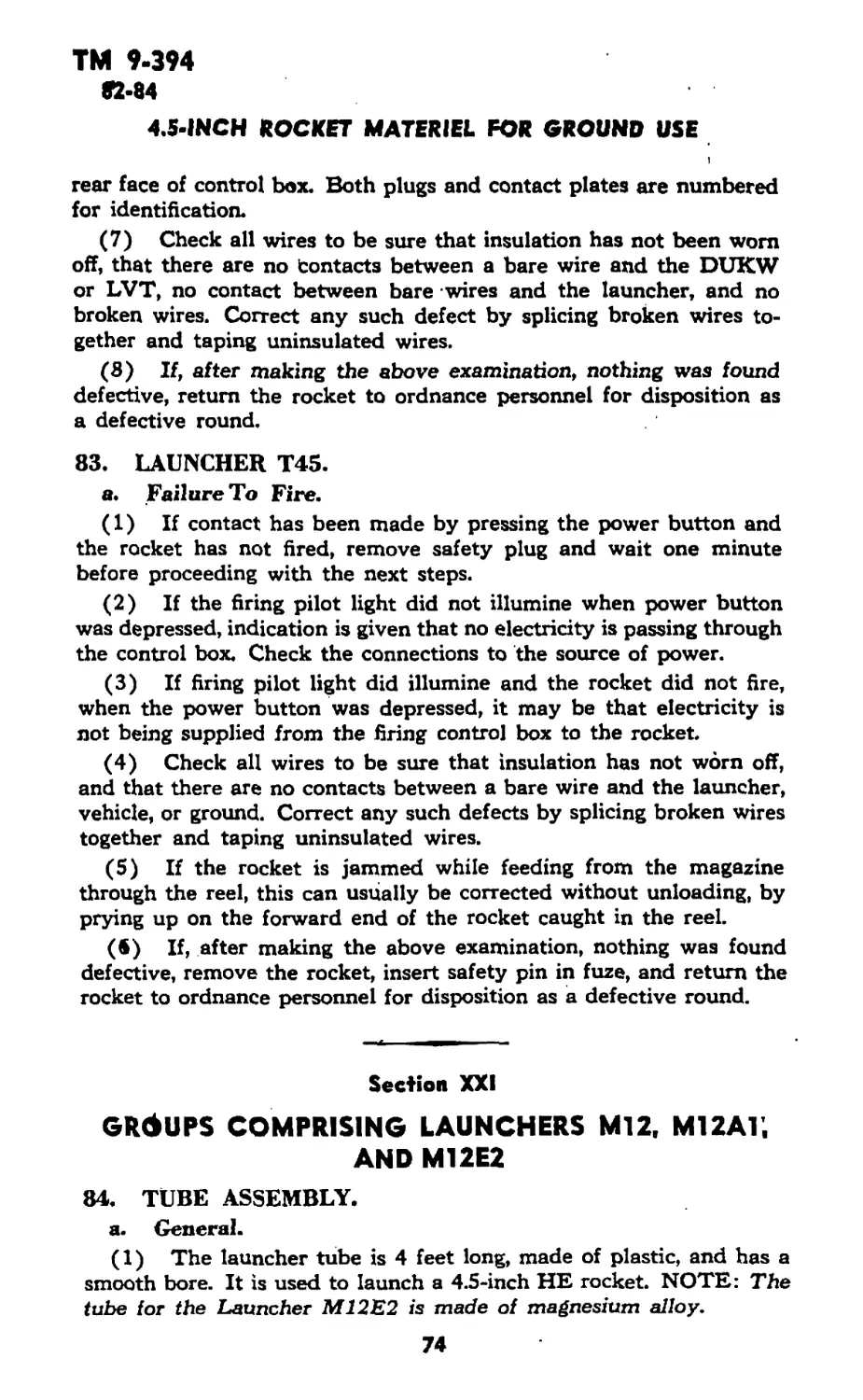
XXI. Groups comprising launchers
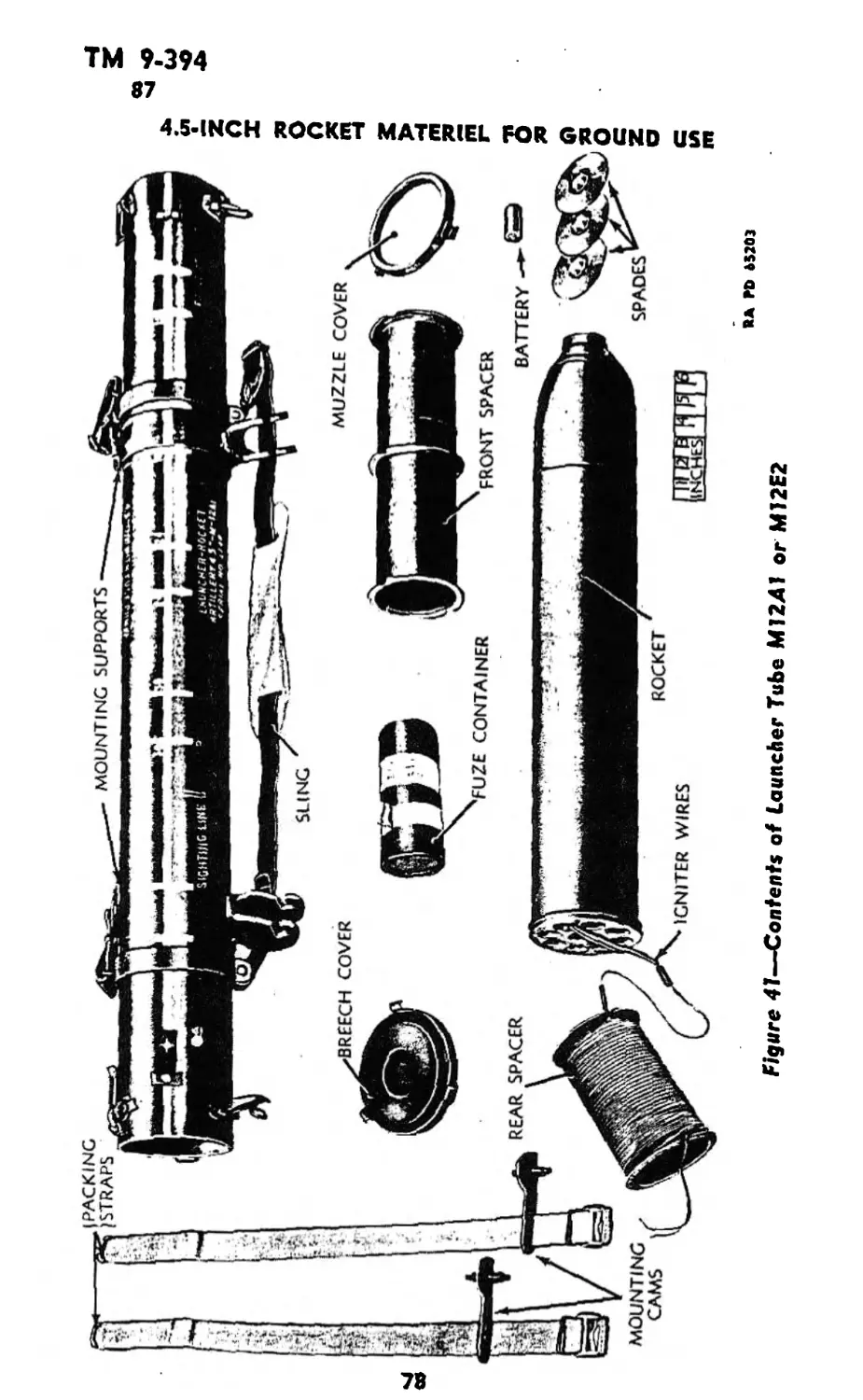
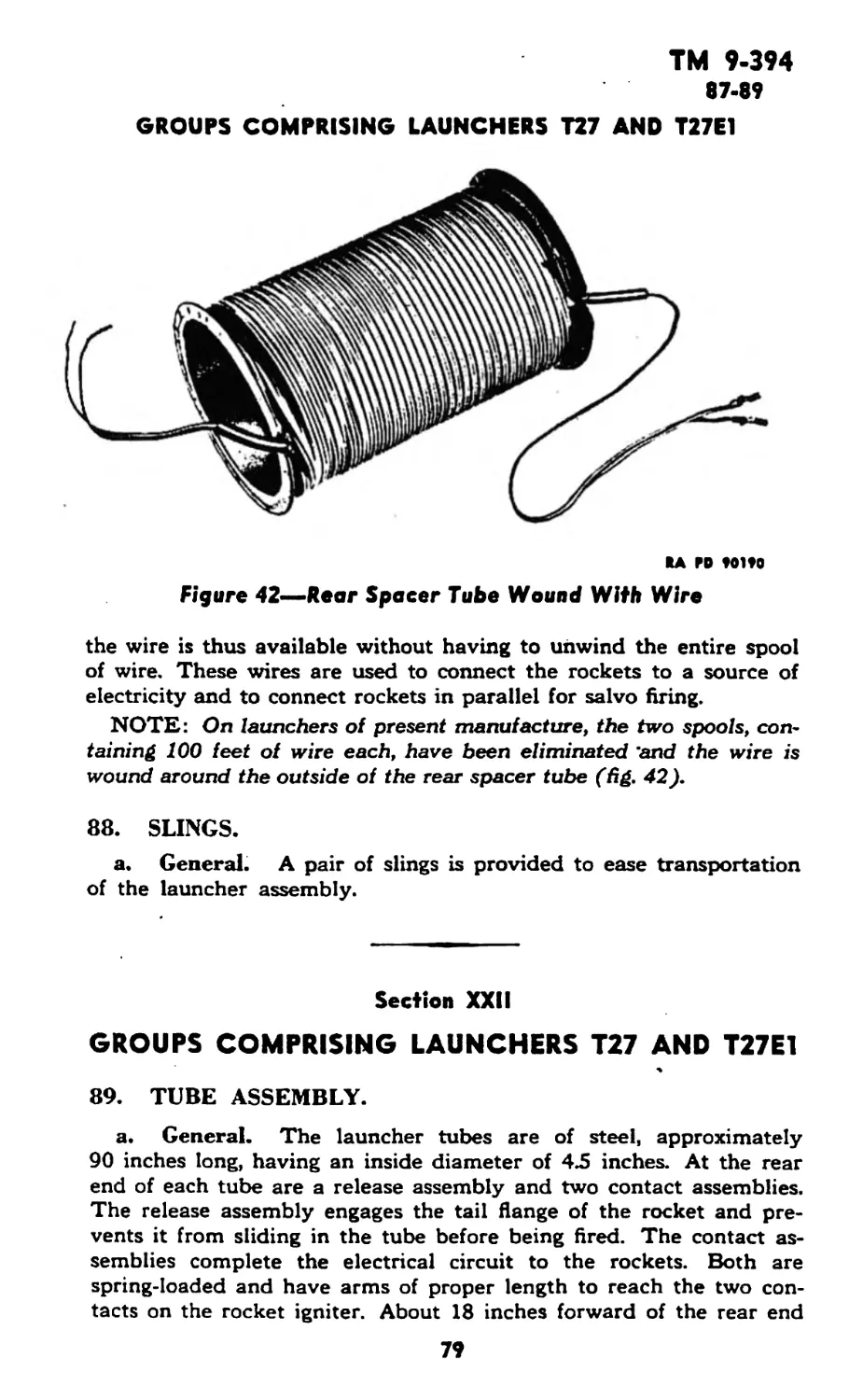
M12, M12A1, and M12E2.. 84- 88 74- 79
XXII. Grotips comprising launchers
T27 and T27E1........... 89- 94 79- 84
XXIII. Groups comprising launchers
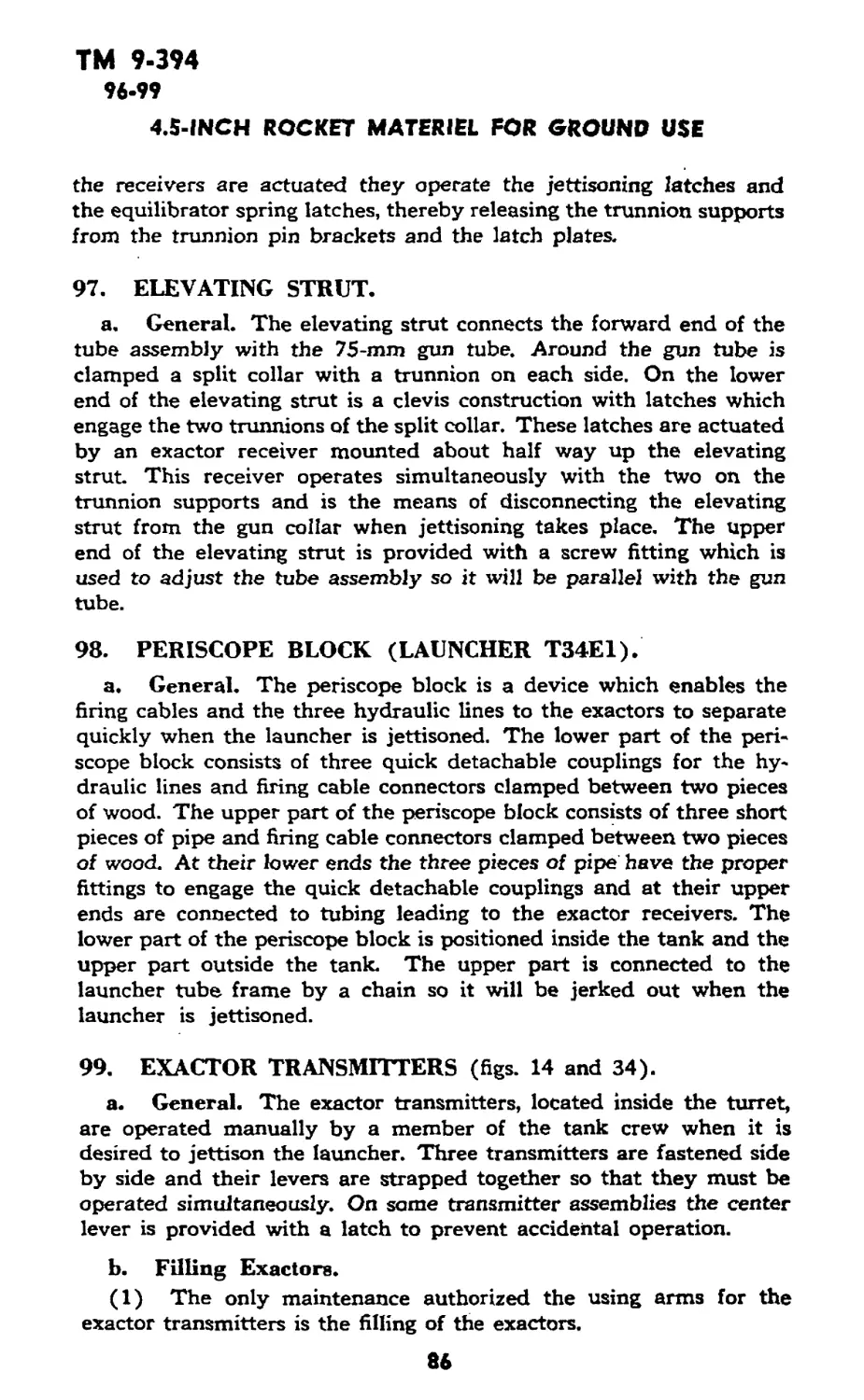
T34 and T34E1...................... 95-100 84- 88
XXIV. Groups comprising launcher
T44 when mounted in 2Уз-
ton, 6x6, amphibian truck,
GMC, DUKW-353.................... 101-106 88- 93
XXV. Groups comprising launcher
T44 when mounted in land-
ing vehicle, tracked (A) (4) 107 93- 94
XXVL Groups comprising launcher
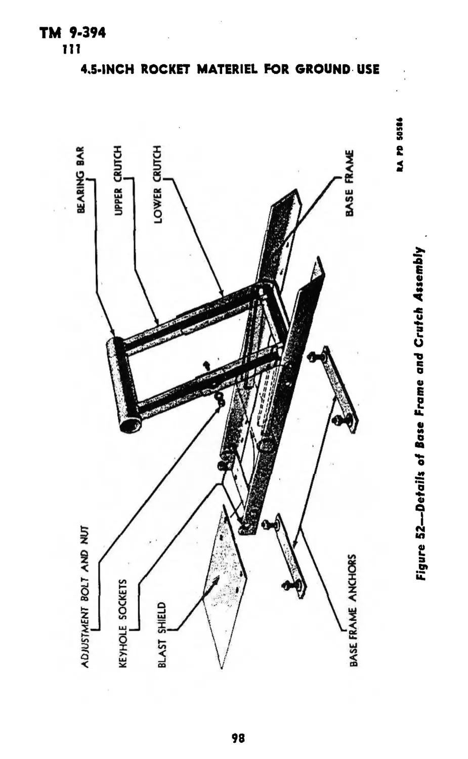
T45 ............................ 108-115 94-100
PART FOUR—AUXILIARY EQUIPMENT
Section XXVII, General....................... 116 101
XXVIII. Ammunition ............... 117-129 101-123
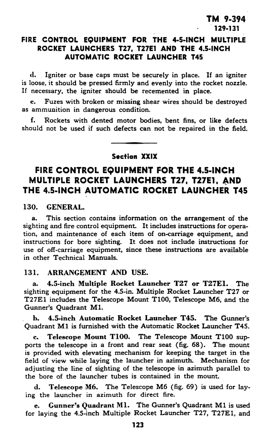
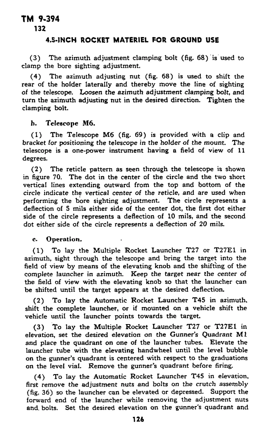
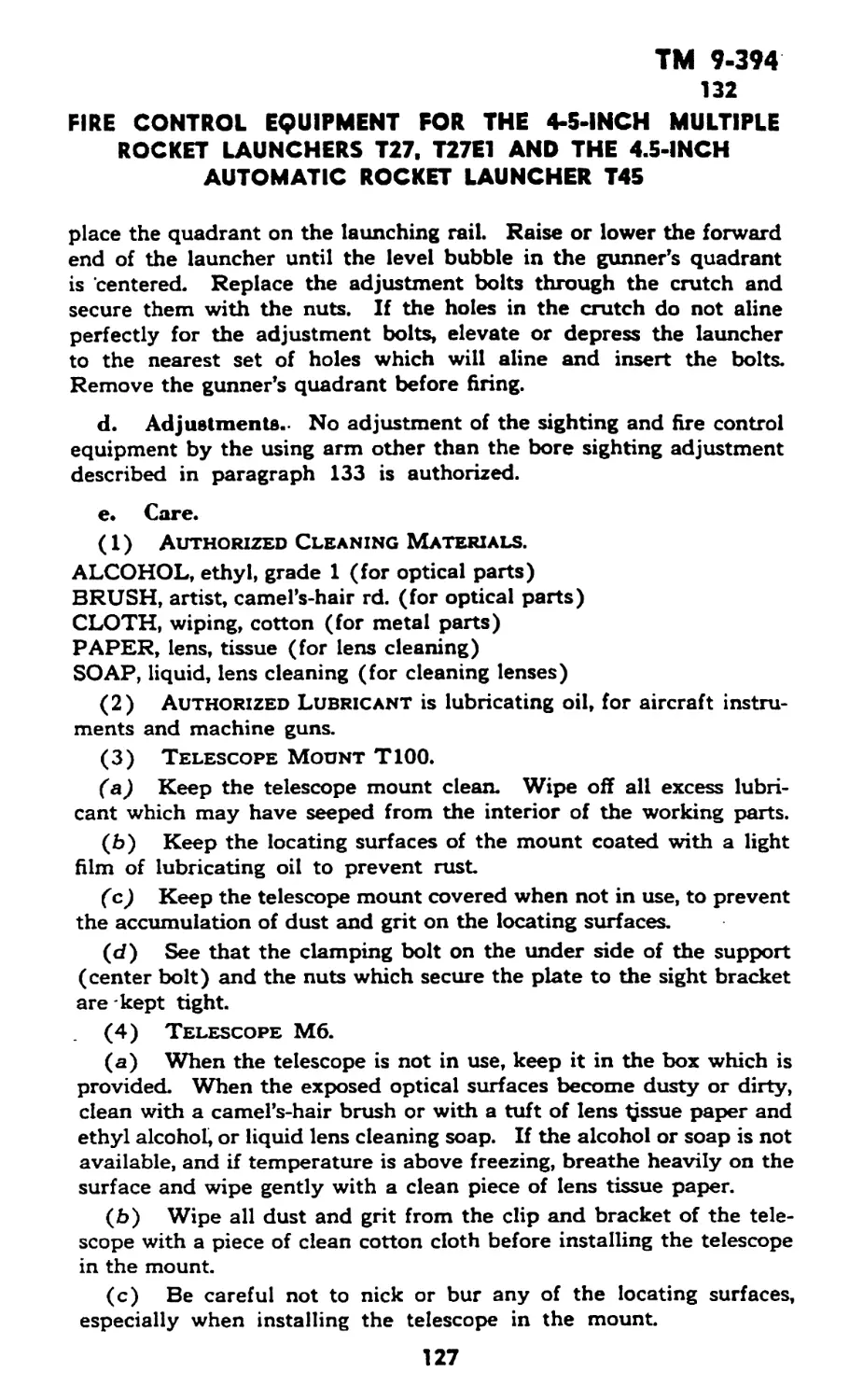
XXIX. Fire control equipment for the
4.5-inch multiple rocket
launchers T27, T27E1, and
the 4.5-inch automatic rocket
launcher T45 .................... 130-133 123-128
APPENDIX
Section XXX Storage and shipment......... 134—136 129—130
XXXI. References ................ 137-139 131-132
Index ........................................... 133-136
ТМ 9-394
RESTRICTED 1
This TM supersedes WDTB 9-393-1, dated 15 May 44; WDTB 9-394-1, dated 2 Feb 45;
and WDTB ORD 121, dated 12 Jul 44. This TM supersedes portions of WDTB ORD 236»
dated 21 Dec 44, which apply to the materiel covered in this TM; however, this ТВ remains
in force until incorporated in other affected TM’i or specifically rescinded.
PART ONE—INTRODUCTION
Section I
GENERAL
1. SCOPE.*
a. This manual is published for the information of the using
arms and services.
b. In addition to a description of the 4.5-inch rocket materiel
listed below this manual contains technical information required for
the identification, use, and care of the materiel, ammunition, and
accessory equipment.
c. In all cases where the nature of the repair, modification, or
adjustment is beyond the scope or facilities of the unit, the respon-
sible ordnance service should be informed so that trained personnel
with suitable tools and equipment may be provided, or proper instruc-
tions issued.
(1) Launchers.
(a) Launcher, rocket, 4.5-inch, M12
(b) Launcher, rocket, 4.5-inch, M12A1
(c) Launcher, rocket, 4.5-inch, M12E2
(d) Launcher, rocket, multiple, 4.5-inch, T27
(e) Launcher, rocket, multiple, 4.5-inch, T27E1
(f) Launcher, rocket, 4.5-inch, T34
(£) Launcher, rocket, 4.5-inch, T34E1
(h) Launcher, rocket, multiple, 4.5-inch, T44
(i) Launcher, rocket, automatic, 4.5-inch, T45
(2) Rockets.
(a) Rockets, M8, M8A1, M8A2, and M8A3
(b) Rockets, M9, M9A1, M9A2, and M9A3
(c) Rocket, T22
(d) Rocket, T46
(e) Rockets, T38E3 and T38E7
(f) Rockets, T39E3 and T39E7
(g) Rocket, HE, beach barrage, 4.5-inch (Navy)
(A) Rocket, smoke, WP, 4.5-inch (Navy)
(3) Fuzes.
(a) Fuzes, M4, M4A1, and M4A2
(b) Fuze, Мб
*To provide operating instructions with the materiel, this Technical Manual has been pub-
lished in advance of complete technical review. Any errors or omissions will be corrected by
changes or, if extensive, by an early revision.
1
TM 9-394
1-4
4.5-INCH ROCKET MATERIEL FOR GROUND USE
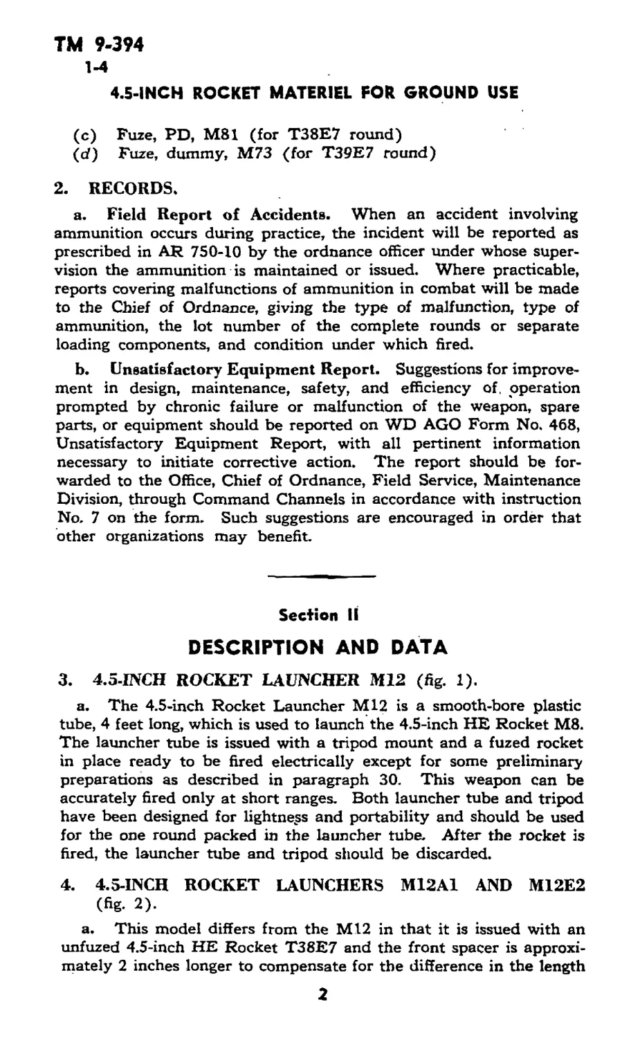
(c) Fuze, PD, M81 (for T38E7 round)
(cf) Fuze, dummy, M73 (for T39E7 round)
2. RECORDS.
a. Field Report of Accidents. When an accident involving
ammunition occurs during practice, the incident will be reported as
prescribed in AR 750-10 by the ordnance officer under whose super-
vision the ammunition is maintained or issued. Where practicable,
reports covering malfunctions of ammunition in combat will be made
to the Chief of Ordnance, giving the type of malfunction, type of
ammunition, the lot number of the complete rounds or separate
loading components, and condition under which fired.
b. Unsatisfactory Equipment Report. Suggestions for improve-
ment in design, maintenance, safety, and efficiency of. operation
prompted by chronic failure or malfunction of the weapon, spare
parts, or equipment should be reported on WD AGO Form No. 468,
Unsatisfactory Equipment Report, with all pertinent information
necessary to initiate corrective action. The report should be for-
warded to the Office, Chief of Ordnance, Field Service, Maintenance
Division, through Command Channels in accordance with instruction
No. 7 on the form. Such suggestions are encouraged in order that
other organizations may benefit.
Section II
DESCRIPTION AND DATA
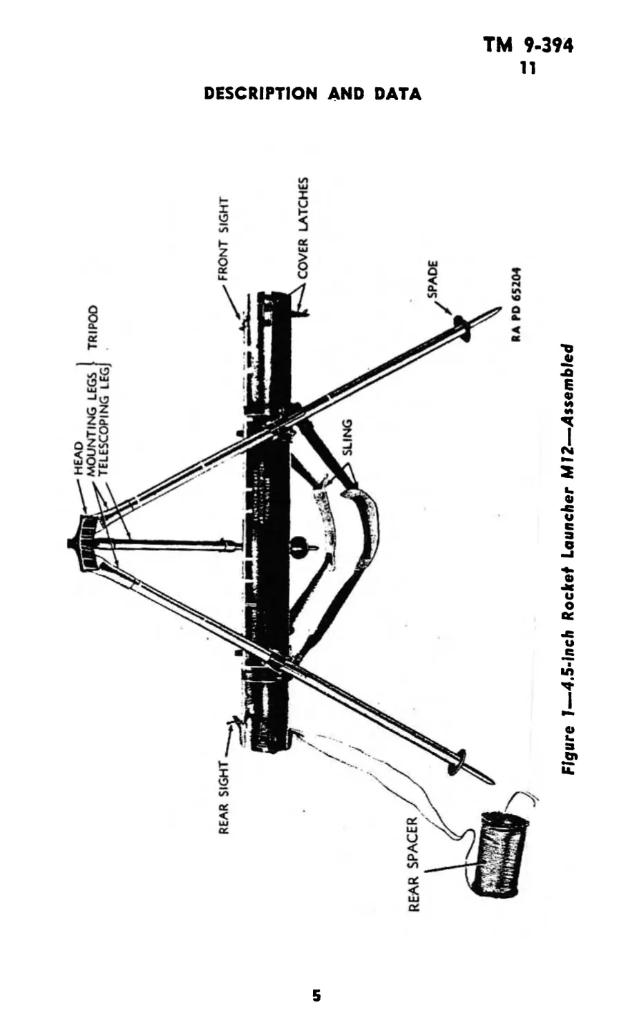
3. 4.5-INCH ROCKET LAUNCHER №12 (fig. 1).
a. The 4.5-inch Rocket Launcher M12 is a smooth-bore plastic
tube, 4 feet long, which is used to launch the 4.5-inch HE Rocket M8.
The launcher tube is issued with a tripod mount and a fuzed rocket
in place ready to be fired electrically except for some preliminary
preparations as described in paragraph 30. This weapon can be
accurately fired only at short ranges. Both launcher tube and tripod
have been designed for lightness and portability and should be used
for the one round packed in the launcher tube. After the rocket is
fired, the launcher tube and tripod should be discarded.
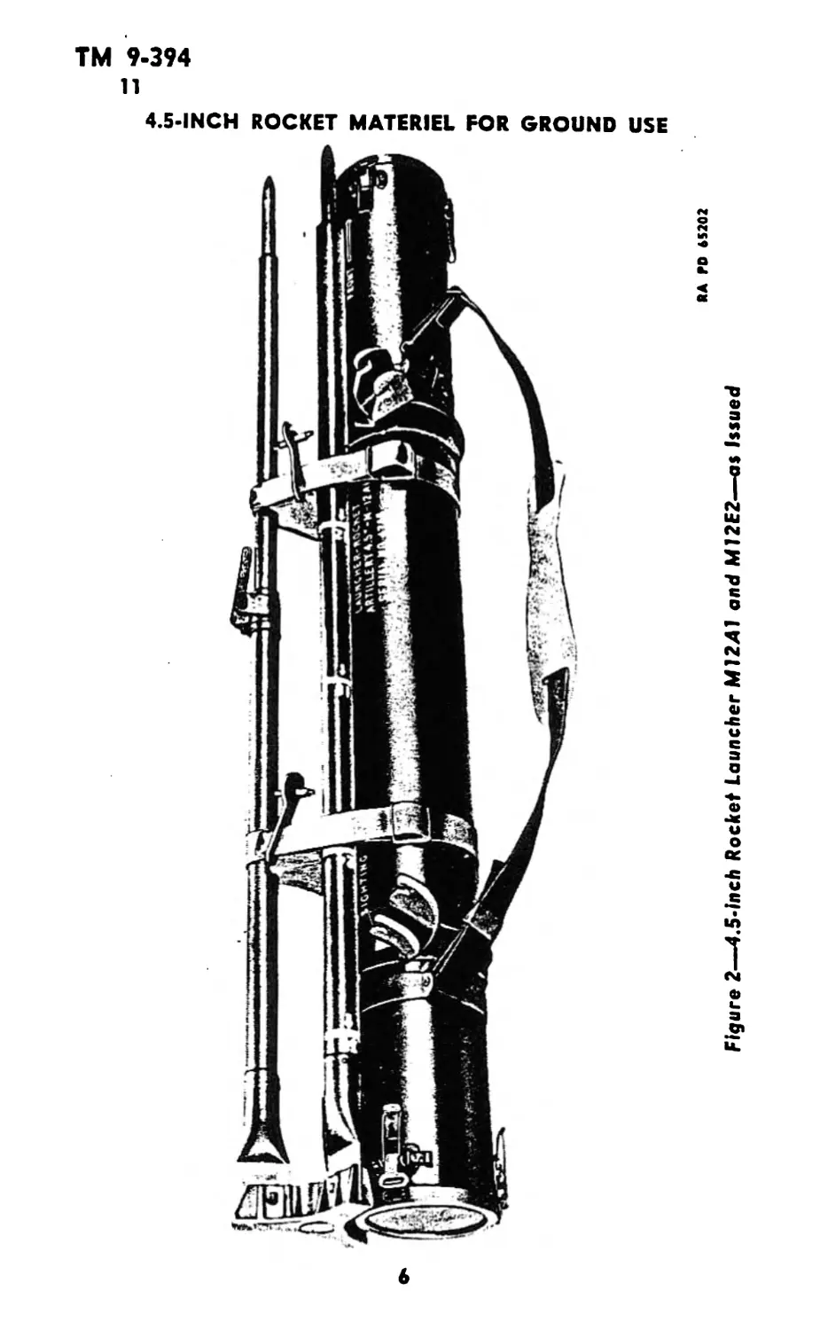
4. 4.5-INCH ROCKET LAUNCHERS M12A1 AND M12E2
(fig. 2).
a. This model differs from the M12 in that it is issued with an
unfuzed 4.5-inch HE Rocket T38E7 and the front spacer is approxi-
mately 2 inches longer to compensate for the difference in the length
2
TM 9-394
4-9
DESCRIPTION AND DATA
of the rocket. The front spacer contains the fuze in a fiber container.
The Launcher M12E2 differs from the M12A1 only in that the tube
is of magnesium alloy instead of plastic.
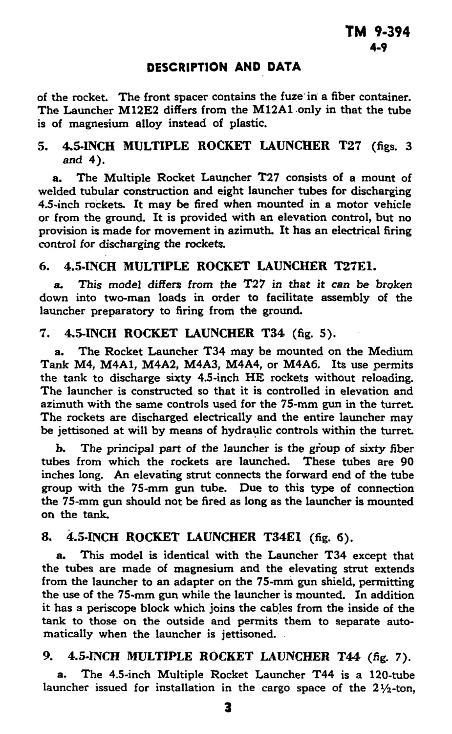
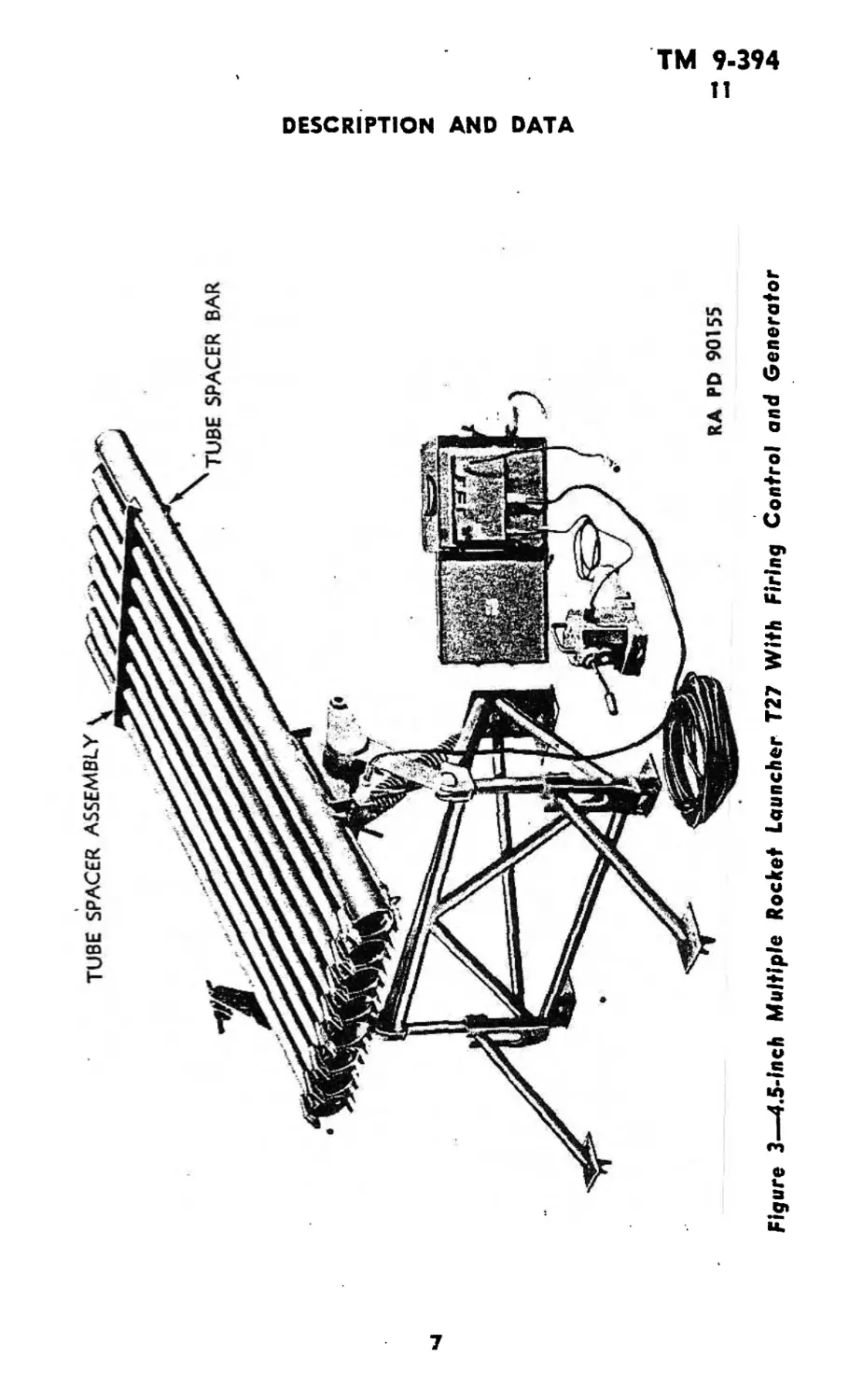
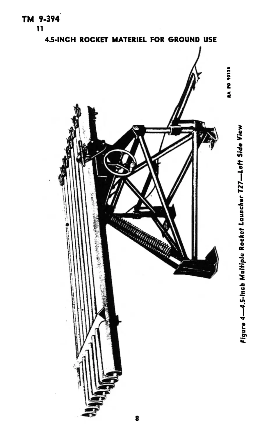
5. 4.5-INCH MULTIPLE ROCKET LAUNCHER T27 (figs. 3
and 4).
a. The Multiple Rocket Launcher T27 consists of a mount of
welded tubular construction and eight launcher tubes for discharging
4.5-inch rockets. It may be fired when mounted in a motor vehicle
or from the ground. It is provided with an elevation control, but no
provision is made for movement in azimuth. It has an electrical firing
control for discharging the rockets.
6. 4.5-INCH MULTIPLE ROCKET LAUNCHER T27E1.
a. This model differs from the T27 in that it can be broken
down into two-man loads in order to facilitate assembly of the
launcher preparatory to firing from the ground.
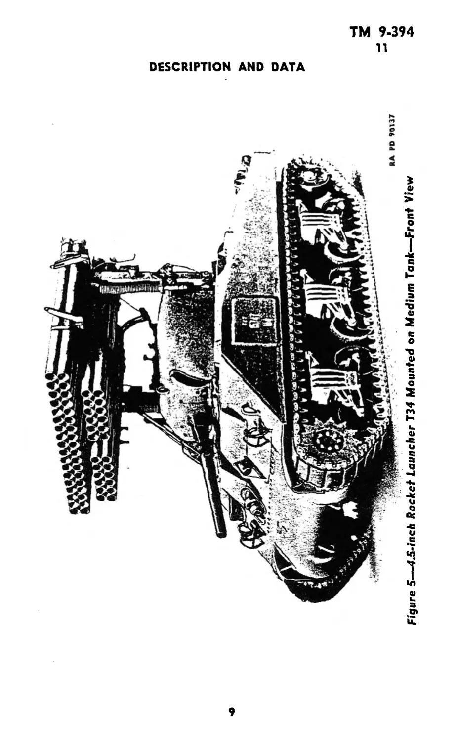
7. 4.5-INCH ROCKET LAUNCHER T34 (fig. 5).
a. The Rocket Launcher T34 may be mounted on the Medium
Tank M4, M4A1, M4A2, M4A3, M4A4, or M4A6. Its use permits
the tank to discharge sixty 4.5-inch HE rockets without reloading.
The launcher is constructed so that it is controlled in elevation and
azimuth with the same controls used for the 75-mm gun in the turret
The rockets are discharged electrically and the entire launcher may
be jettisoned at will by means of hydraulic controls within the turret
b. The principal part of the launcher is the group of sixty fiber
tubes from which the rockets are launched. These tubes are 90
inches long. An elevating strut connects the forward end of the tube
group with the 7 5-mm gun tube. Due to this type of connection
the 75-mm gun should not be fired as long as the launcher is mounted
on the tank.
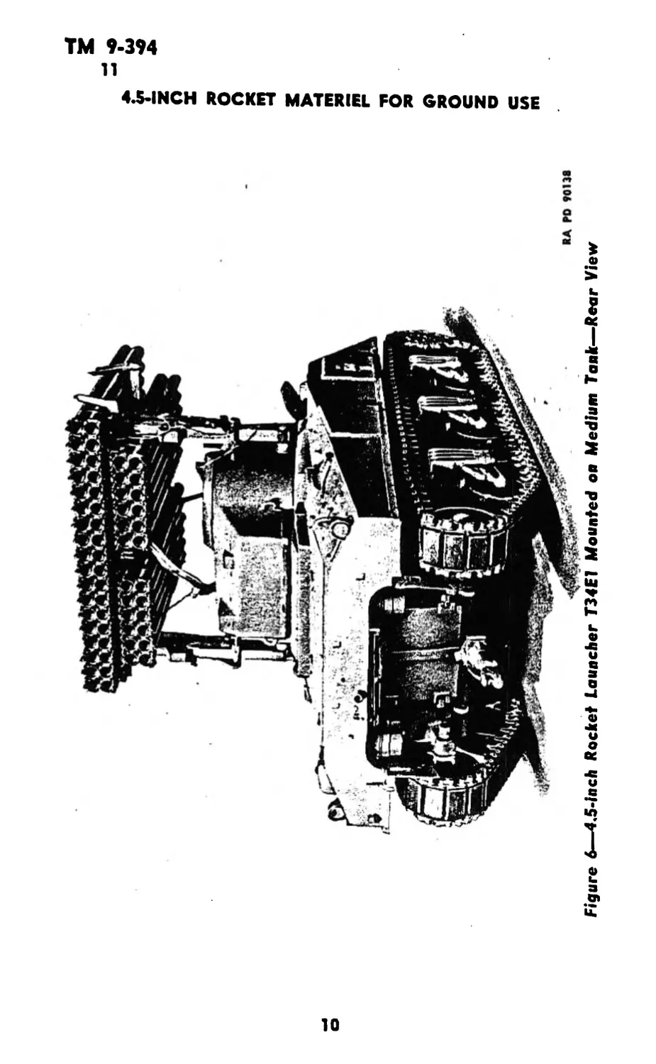
8. 4.5-INCH ROCKET LAUNCHER T34E1 (fig. 6).
a. This model is identical with the Launcher T34 except that
the tubes are made of magnesium and the elevating strut extends
from the launcher to an adapter on the 75-mm gun shield, permitting
the use of the 75-mm gun while the launcher is mounted. In addition
it has a periscope block which joins the cables from the inside of the
tank to those on the outside and permits them to separate auto-
matically when the launcher is jettisoned.
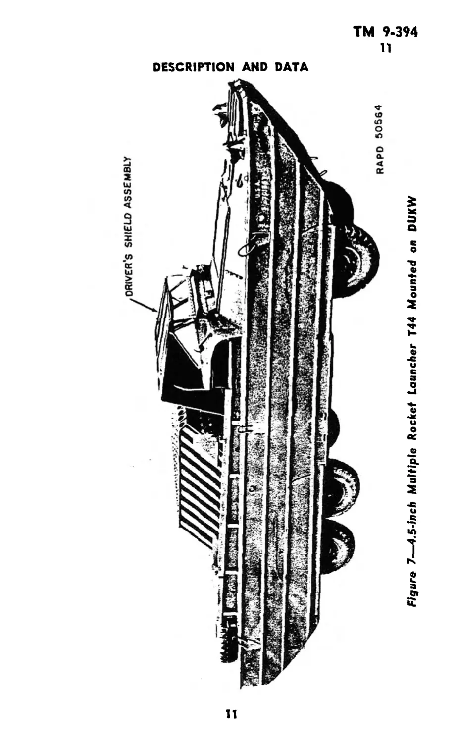
9. 4.5-INCH MULTIPLE ROCKET LAUNCHER T44 (fig. 7).
a. The 4.5-inch Multiple Rocket Launcher T44 is a 120-tube
launcher issued for installation in the cargo space of the 2x/2-ton,
3
ТМ 9-394
9-11
4.5- INCH ROCKET MATERIEL FOR GROUND USE
6x6, amphibian truck, GMC, DUKW-353. However, the launcher
can be installed in the cargo space of the Landing Vehicle, tracked
(armored), Mk. IV. The launcher has an electric firing system,
controlled by the со-driver, which uses current from the vehicle
ignition system and which can fire 120 4.5-inch beach barrage HE
rockets in either ripple or single action fire.
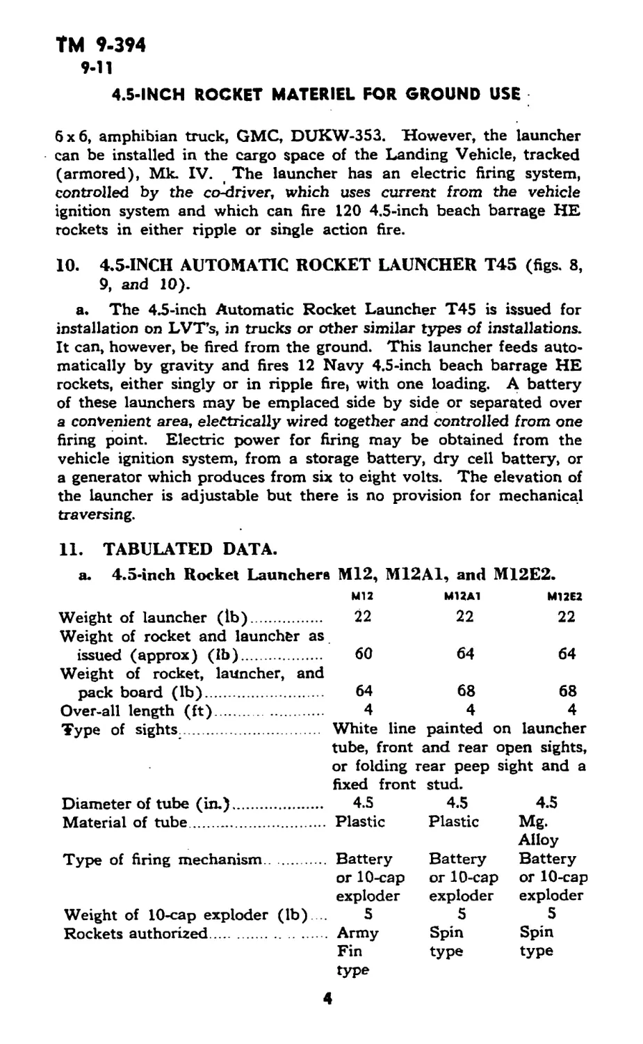
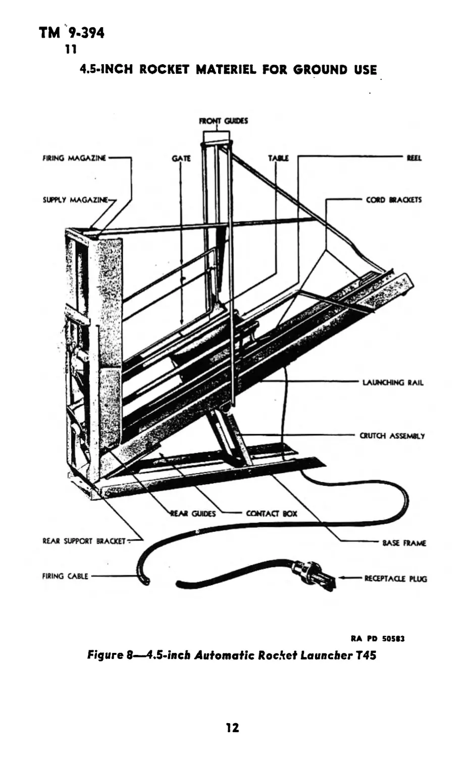
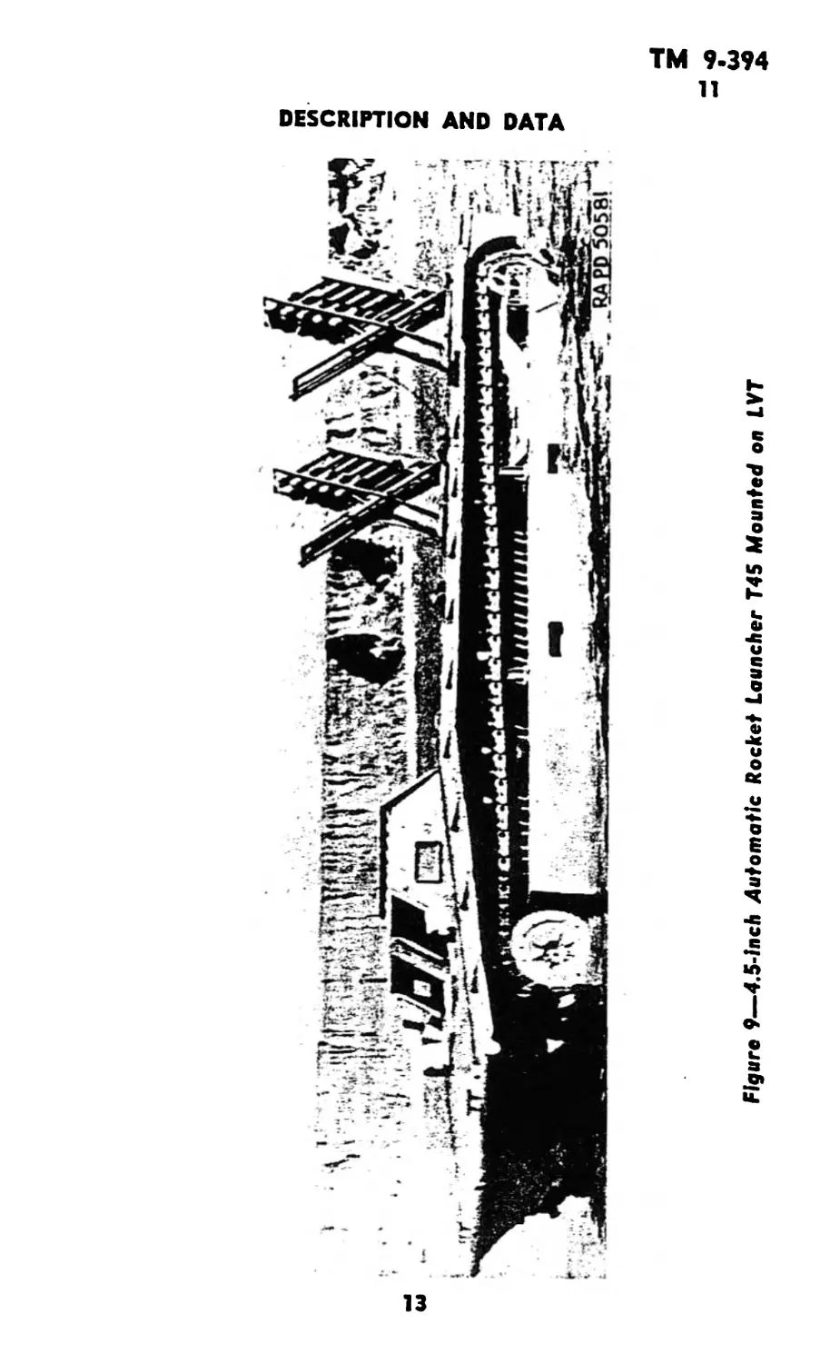
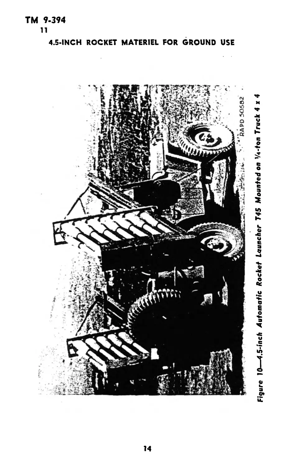
10. 4.5-INCH AUTOMATIC ROCKET LAUNCHER T45 (figs. 8,
9, and 10).
a. The 4.5-inch Automatic Rocket Launcher T45 is issued for
installation on LVT’s, in trucks or other similar types of installations.
It can, however, be fired from the ground. This launcher feeds auto-
matically by gravity and fires 12 Navy 4.5-inch beach barrage HE
rockets, either singly or in ripple fire> with one loading. A battery
of these launchers may be emplaced side by side or separated over
a convenient area, electrically wired together and controlled from, one
firing point. Electric power for firing may be obtained from the
vehicle ignition system, from a storage battery, dry cell battery, or
a generator which produces from six to eight volts. The elevation of
the launcher is adjustable but there is no provision for mechanical
traversing.
11. TABULATED DATA.
a. 4.5-inch Rocket Launchers M12, M12A1, and M12E2.
Ml 2 M12A1 M12E2
Weight of launcher (ib) Weight of rocket and launcher as 22 22 22
issued (approx) (ib) Weight of rocket, launcher, and 60 64 64
pack board (lb) 64 68 68
Over-all length (ft) 4 4 4
Type of sights. White line tube, front painted on launcher and rear open sights,
or folding rear peep sight and a fixed front stud.
Diameter of tube (in.) 4.5 4.5 4.5
Material of tube Plastic Plastic Mg. Alloy
Type of firing mechanism Battery or 10-cap exploder Battery or 10-cap exploder Battery or 10-cap exploder
Weight of 10-cap exploder (lb).... 5 5 5
Rockets authorized Army Fin Spin type Spin type
type
4
Ml
TM 9-394
11
4.5-INCH ROCKET MATERIEL FOR GROUND USE
Figure 2—4.5-inch Rocket Launcher M12A1 and M12E2—as Issued
6
Figure 3—4.5-inch Multiple Rocket Launcher T27 With Firing Control and Generator
о
5
►
Figure 4—4,5.ineh
Multiple Лоске! Launcher
727—Left Side View
•А FO 90)3$
TM 9-394
11
DESCRIPTION AND DATA
Figure 5—-4.5-inch Rocket Launcher 734 Mounted on Medium Tank-—Front View
9
TM 9-394
11
«Л-INCH ROCKET MATERIEL FOR GROUND
USE
10
driver's shield assembly
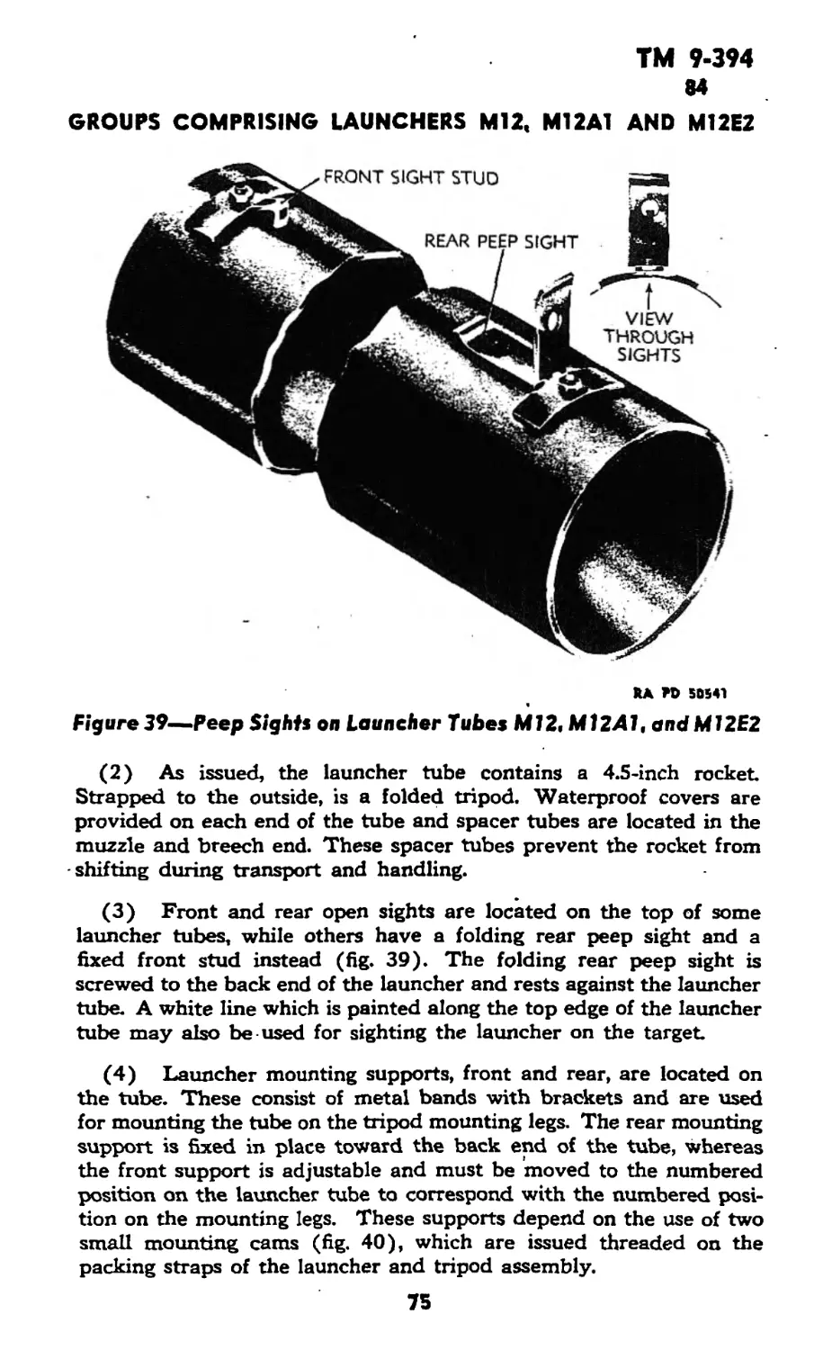
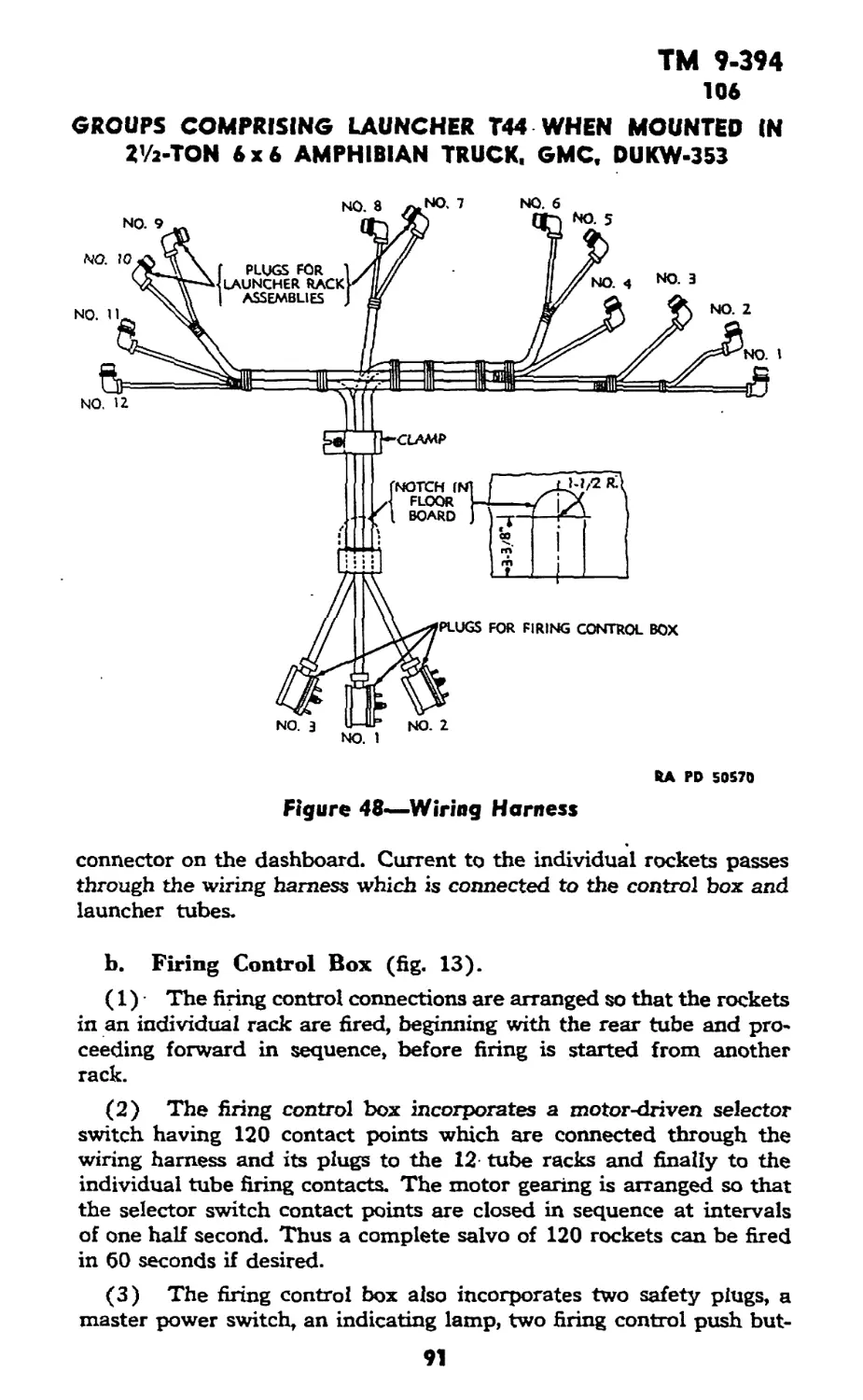
Figure 7—4.5-inch Multiple Rocket Launcher T44 Mounted on DUKW
TM 9-394
11
4.5-INCH ROCKET MATERIEL FOR GROUND USE
RA PD 505(3
Figure 8—4.5-inch Automatic Rochet Launcher T45
12
Figure 9—4.5-inch Automatic Rocket Launcher T4S Mounted on LVT
TM 9-394
11
4.5-INCH ROCKET MATERIEL FOR GROUND USE
Figure 10—4.5-inch Automatic Rocket Launcher 745 Mounted on Ул-ton Truck 4x4
14
TM 9-394
11
DESCRIPTION AND DATA
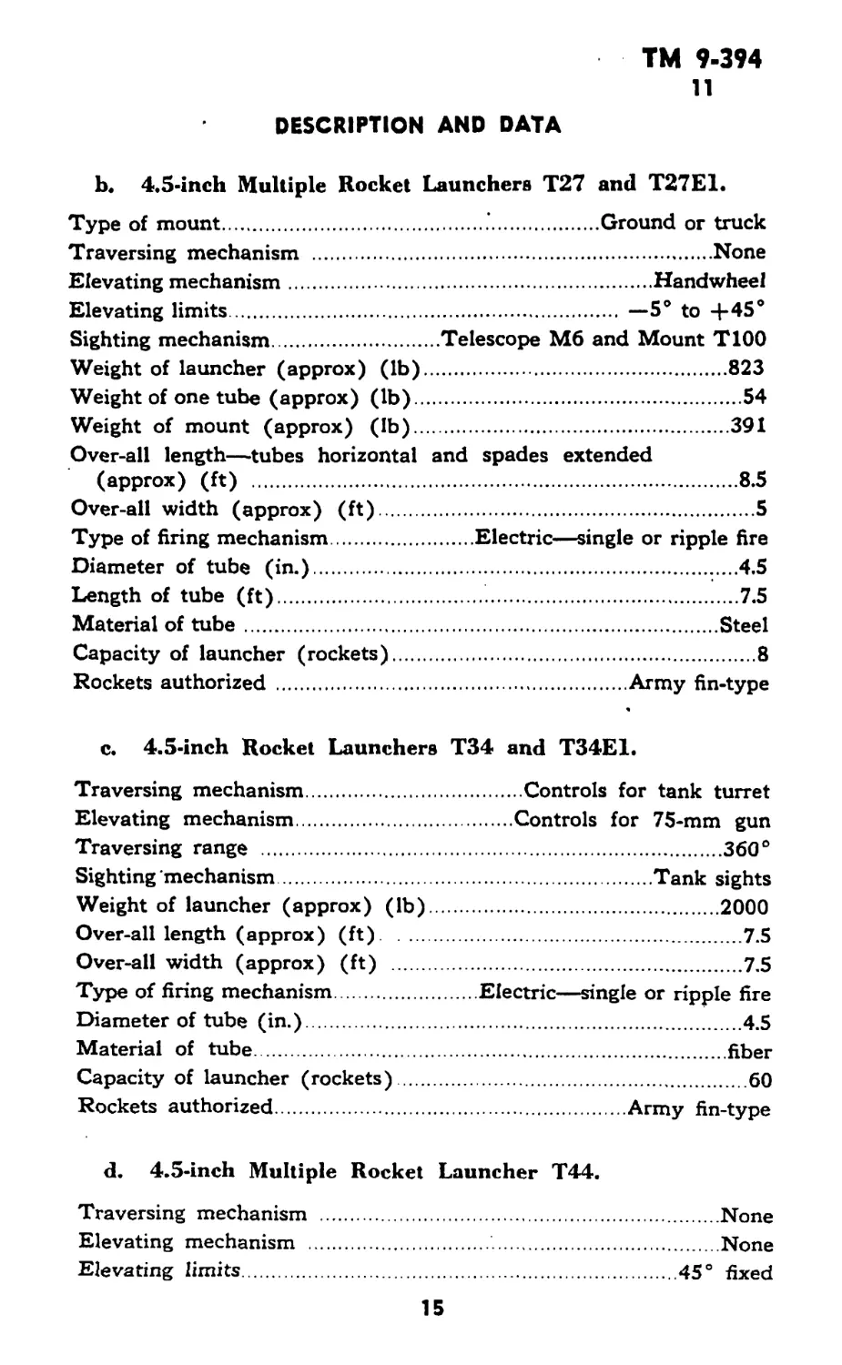
b. 4.5-inch Multiple Rocket Launchers T27 and T27E1.
Type of mount.................................. Ground or truck
Traversing mechanism ....................................None
Elevating mechanism................................Handwheel
Elevating limits................................. —5’ to 4-45°
Sighting mechanism...............Telescope M6 and Mount T100
Weight of launcher (approx) (lb)..........................823
Weight of one tube (approx) (lb)..........................54
Weight of mount (approx) (lb).............................391
Over-all length—tubes horizontal and spades extended
(approx) (ft) ..............
Over-all width (approx) (ft).
Type of firing mechanism....
Diameter of tube (in.)......
Length of tube (ft).........
Material of tube............
Capacity of launcher (rockets)
Rockets authorized..........
.8.5
.5
Electric—single or ripple fire
......4.5
.............L..7.5
.Steel
.8
.Army fin-type
c. 4.5-inch Rocket Launchers T34 and T34E1.
Traversing mechanism............
Elevating mechanism.............
Traversing range ...............
Sighting mechanism..............
Weight of launcher (approx) (lb)
Over-all length (approx) (ft)...
Over-all width (approx) (ft) ...
Type of firing mechanism........
Diameter of tube (in.)..........
Material of tube................
Capacity of launcher (rockets)..
Rockets authorized..............
...Controls for tank turret
...Controls for 75-mm gun
...360°
...Tank sights
...2000
...7.5
...7.5
Electric—single or ripple fire
...' 4.5
...fiber
...60
...Army fin-type
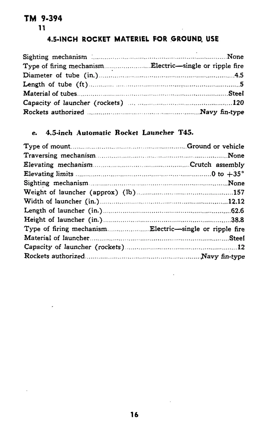
d. 4.5-inch Multiple Rocket Launcher T44.
Traversing mechanism ............................
Elevating mechanism ................... .........
Elevating limits.................................
....None
....None
45° fixed
15
ТМ 9-394
11
4.5-INCH ROCKET MATERIEL FOR GROUND, USE
Sighting mechanism ;.....................................None
Type of firing mechanism...........Electric—single or ripple fire
Diameter of tube (in.)....................................4.5
Length of tube (ft)........................................ 5
Material of tubes.......................................Steel
Capacity of launcher (rockets) ...........................120
Rockets authorized ...............................Navy fin-type
e. 4.5-inch Automatic Rocket Launcher T45.
Type of mount...................................Ground or vehicle
Traversing mechanism........................................None
Elevating mechanism.............................Crutch assembly
Elevating limits.......................................0 to 4-35°
Sighting mechanism..........................................None
Weight of launcher (approx) (lb).............................157
Width of launcher (in.)......................................12.12
Length of launcher (in.)......................................62.6
Height of launcher (in.)......................................38.8
Type of firing mechanism..............Electric—single or ripple fire
Material of launcher.........................................Steel
Capacity of launcher (rockets)..................................12
Rockets authorized...................................Navy fin-type
16
ТМ 9-394
12-15
PART TWO—OPERATING INSTRUCTIONS
Section III
GENERAL
12. SCOPE.
a. Part two contains information for the guidance of the per-
sonnel responsible for the operation of this equipment. It contains
information on the operation of the equipment with the description
and location of the controls.
Section IV
SERVICE UPON RECEIPT OF EQUIPMENT
13. GENERAL.
a. Upon receipt of new or used materiel, it is the responsibility
of the officer in charge to ascertain whether it is complete and in
sound operating condition. A record should be made of any missing
parts and of any malfunctions, and any such conditions should be
corrected as quickly as possible.
b. Attention should be given to small and minor parts as these
are the most likely to become lost and may seriously affect the proper
functioning of the materiel.
c. The materiel should be cleaned and prepared for service in
accordance with instructions given in this section.
14. LAUNCHER M12.
a. As issued, these launchers are ready for service after emplace-
ment as covered in paragraph 30.
15. LAUNCHERS M12A1 AND M12E2.
a. Since the rocket is shipped in the launcher tube unfuzed, it
is necessary to assemble the fuze to the rocket before use. This
should be done, if practicable, before going into action because the
fuze is boresafe and no additional hazard is involved.
b. Remove waterproof caps from launcher tube. Remove muzzle
spacer tube and remove fuze container from spacer. Save tissue
paper packing.
c. Push the rear spacer with the rocket ahead of it until the
nose of the rocket protrudes from the muzzle of the tube.
d. Assemble fuze to rocket as outlined in paragraph’ 128.
e. Replace breech cover on tube.
17
TM 9-394
15-17
4.5- INCH ROCKET MATERIEL FOR GROUND USE
f. Push rocket back in the tube until rear spacer seats against
breech cap.
g. Replace tissue paper in rear end of front spacer and replace
spacer so that it encircles the fuze. Use caution when replacing
spacer.
h. Replace muzzle cap.
16. LAUNCHERS T27 AND T27E1.
a. New Equipment.
(1) Test firing control as follows: CAUTION: Make sure no
rockets are in launcher tubes.
(a) Connect generator cable between control box and generator.
(b) Insert firing cord plug in its socket.
(c) Insert safety plug in its socket.
(d) Move “safe” key to fire position.
(e) If indicator is not at zero, reset it by cranking generator
until dial lamp on control box lights and depress firing button.
(f) Move “reset” key to fire position.
(g) While cranking generator, depress firing button. Pointer on
dial should advance step by step until button is released.
(h) Reset indicator to zero.
(i) Restore “safe” key to “safe” position.
(j) Remove safety plug.
(2) Remove rust-preventive compound from tubes and from
contact fingers and latches by scrubbing with dry-cleaning solvent
and then wipe thoroughly dry, using clean, dry burlap, or wiping cloths.
(3) Apply a light coat of preservative lubricating oil (special)
to tubes and all base metal surfaces. Apply a few drops of pre-
servative lubricating oil (special) to release assemblies.
b. Used Equipment.
(1) Test firing control as outlined in a (1) above and remove
rust-preventive compound as outlined in a (2) above.
(2) Inspect contact fingers and latches to be sure that they are
not broken and that the springs are operating properly.
17. LAUNCHERS T34 AND T34E1.
a. New Equipment.
(1) Inspect the launcher for obstructions inside the tubes.
(2) Test fire control as follows: CAUTION: Make sure no
rockets are in the launcher tubes.
(a) Insert safety* plug in its receptacle in left side of box.
18
TM 9-394
17-20
CONTROLS FOR LAUNCHERS Ml2. M12A1. AND M12E2
(b) Move “reset” key on top of control box to “fire.” Move
“safe” key to top of control box to “fire.” Red signal lamp on top
of box should then light.
(c) Press button in end of firing cord. As long as button is de-
pressed, dial pointer on front of box should move around step by step.
(d) Reset firing control as outlined in paragraph 43 k.
b. Used Equipment.
(1) The instructions outlined above for new equipment are also
applicable for used equipment. In addition the launcher tubes should
be inspected for cracks near the muzzle and breech end. Minor flakes
or blisters on the inside of the tubes will not affect operation of
the launcher.
(2) Inspect the contact fingers and latches to be sure that they
are not bent out of shape or broken and that the springs are func-
tioning properly.
18. LAUNCHER T44.
a. New and Used Equipment.
(1) Inspect the launcher for obstructions inside the tubes.
(2) Remove rust-preventive compound from the tube by scrub-
bing with dry-cleaning solvent and then wipe the tubes thoroughly
dry, using clean, dry burlap, or wiping cloths.
(3) Inspect the troughs at the bottom of the 12 tube rack
assemblies for obstructions.
(4) Apply a light coat of preservative lubricating oil (special)
to tubes and base metal surfaces. Apply a few drops of preservative
lubricating oil (special) to release assemblies.
19. LAUNCHER T45.
a. New and Used Equipment.
(1) Remove rust-preventive compound by scrubbing with dry-
cleaning solvent and then wiping thoroughly dry, using clean, dry
burlap, or wiping cloths.
Section V
CONTROLS FOR LAUNCHERS M12. Ml 2 Al, AND M12E2
20. TWO-CELL BATTERY.
a. A two-cell battery (flashlight type) located in the front spacer
tube is used to fire a single rocket from the launcher tube.
19
ТМ 9-394
21-22
4.5- INCH ROCKET MATERIEL FOR GROUND USE
RA PO 13441
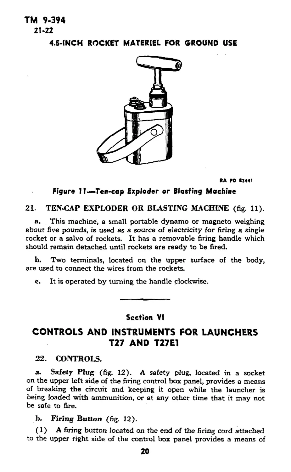
Figure 11—Ten-cap Exploder or Blasting Machine
21- TEN-CAP EXPLODER OR BLASTING MACHINE (fig. 11).
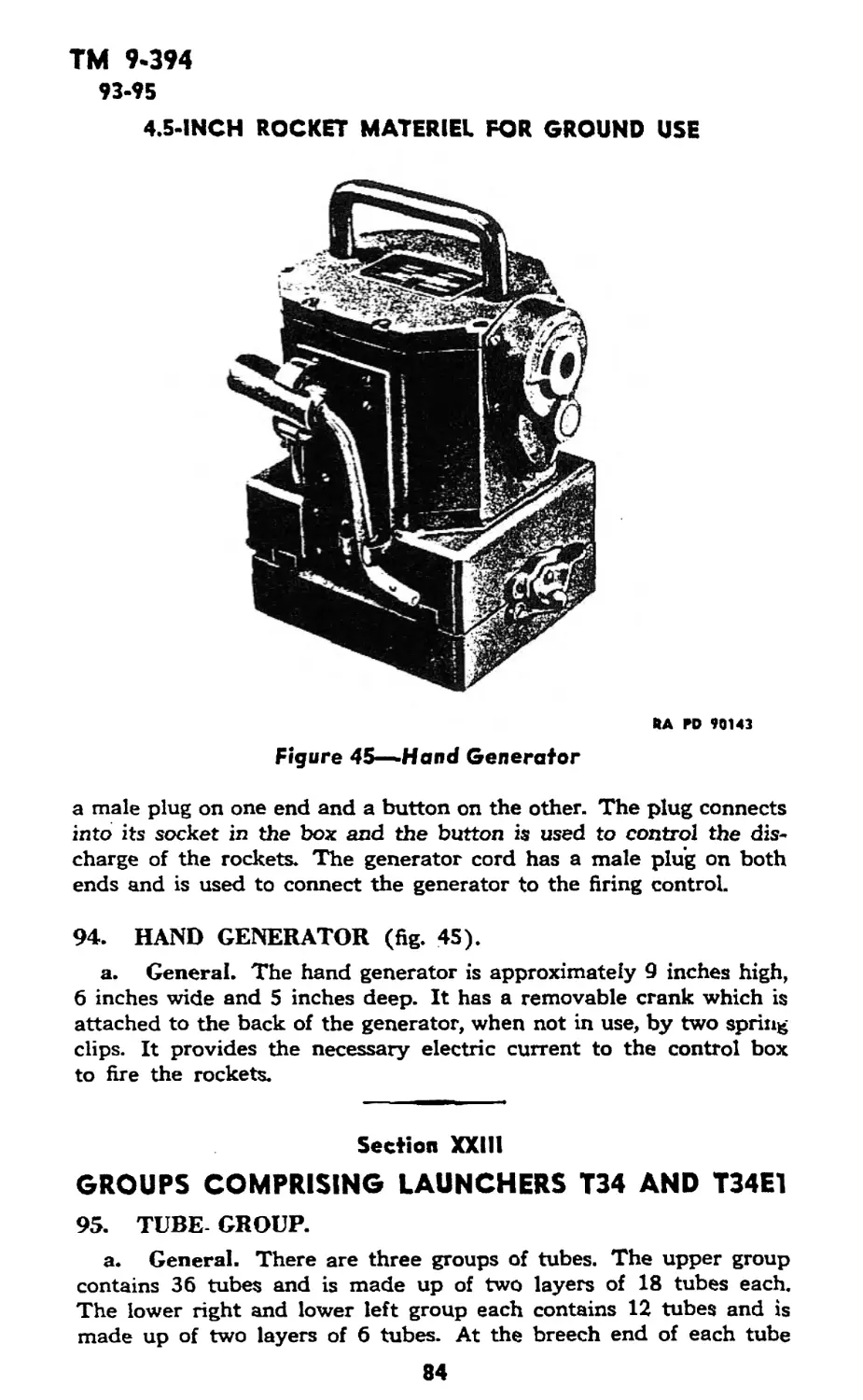
a. This machine, a small portable dynamo or magneto weighing
about five pounds, is used as a source of electricity for firing a single
rocket or a salvo of rockets. It has a removable firing handle which
should remain detached until rockets are ready to be fired.
b. Two terminals, located on the upper surface of the body,
are used to connect the wires from the rockets.
c. It is operated by turning the handle clockwise.
Section VI
CONTROLS AND INSTRUMENTS FOR LAUNCHERS
T27 AND T27E1
22. CONTROLS.
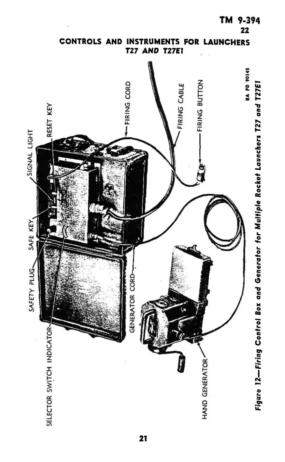
a. Safety Plug (fig. 12). A safety plug, located in a socket
on the upper left side of the firing control box panel, provides a means
of breaking the circuit and keeping it open while the launcher is
being loaded with ammunition, or at any other time that it may not
be safe to fire.
h. Firing Button (fig. 12).
(1) A firing button located on the end of the firing cord attached
to the upper right side of the control box panel provides a means of
20
Figure 12—Firing Control Box and Generator for Multiple Rocket Launchers T27 and T27E1 *
TM 9-394
22-23
4.5-INCH ROCKET MATERIEL FOR GROUND USE
completing the electric circuit to the rockets in order that they may
be fired.
(2) To operate, depress the button.
c. Safe Key (fig. 12).
(1) A safe key located on the upper center part of the control
box panel provides a means of breaking the circuit to the firing button.
(2) This key has two positions. When vertical it is in the safe
position and when moved to the right it completes the circuit to the
firing button. It is manually moved to either position.
d. Reset Key (fig. 12).
(1) A reset key, located on the upper center part of the control
box panel to the right of the safe key provides a means of resetting the
firing Control after firing has stopped, in order that the firing sequence
will start with No. 1 tube when the firing button is again depressed.
(2) The reset key has two positions. When vertical it is in the
reset position and when moved to the left it is in the firing position.
It is manually moved to either position.
e. Elevating Handwheel. An elevating handwheel is attached
to the left side of the mount. This handwheel is turned counterclock-
wise to elevate the launcher tubes, and clockwise to depress them.
23. INSTRUMENTS.
a. Selector Switch Indicator (fig. 12).
(1) In the center of the firing control box panel is a selector
switch indicator enclosed by a window.
(2) It consists of a dial with eight numbered graduations and a
pointer which shows the position of the selector switch and, therefore,
the number of rockets fired.
b. Signal Light (fig. 12).
(1) On the upper center part of the control box panel is a red
signal light.
(2) This light illuminates when the hand generator is turned with
the safety plug in position and the safe key moved to the fire position.
It indicates that sufficient current is entering the control box to fire
the rockets.
22
ТМ 9-394
24
Section VII
CONTROLS AND INSTRUMENTS FOR LAUNCHERS
T34 AND T34E1
24. CONTROLS.
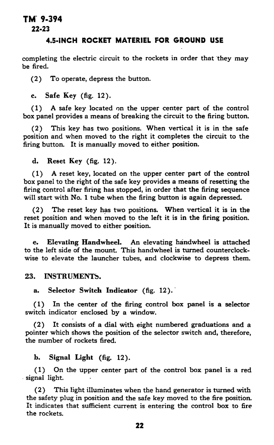
a. Safety Plug (fig. 13).
(1) A safety plug is located in a socket on the left side of the
firing control box. When this plug is removed from its socket, it
breaks the circuit to the firing button and keeps it open while the
launcher is being loaded with ammunition, or at any other time that
it may not be safe to fire.
(2) To remove the safety plug withdraw it from its socket.
b. Firing Button (fig. 13).
(1) A firing button, located in the end of the firing cord attached
to the left side of the control box, provides a means of completing
the electric circuit to the rockets, in order that they may be fired.
(2) To operate, depress the button.
c. Safe Key (fig. 13).
(1) A safe key, located on the top of the control box, provides
a means of completing the circuit to the firing button.
(2) This key has two positions. When vertical, it is in the “safe”
position and, when moved to the right, it is in the “fire” position.
It is moved manually to either position.
d. Reset Key (fig. 13).
(1) A reset key, located on top of the control box to the right
of the safe key, provides a means of resetting the firing control box
after firing has stopped, in order that the firing sequence will start
with-No. 1 tube, when firing button is again depressed.
(2) The reset key has two positions. When vertical it is in the
reset position and, when moved to the left, it is in the fire position.
It is moved manually to either position.
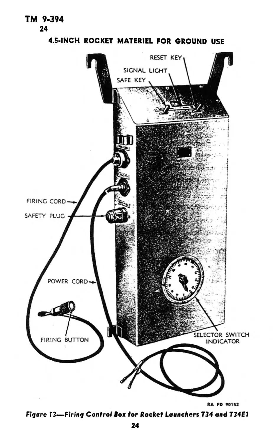
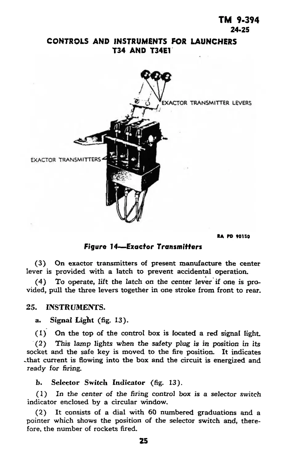
e. Exactor Transmitters (fig. 14).
(1) The exactor transmitters are manually operated controls
located inside the turret and are for the purpose of jettisoning the
launcher.
(2) Three transmitters are fastened side by side and their
levers are strapped together so that they must be operated simul-
taneously.
23
TM 9-394
24
4.5-INCH ROCKET MATERIEL FOR GROUND USE
RA PD 90152
Figure 13—Firing Control Box for Rocket Launchers T34 and T34E1
24
ТМ 9-394
24-25
CONTROLS AND INSTRUMENTS FOR LAUNCHERS
T34 AND T34E1
KA PD 90150
Figure 14—Exactor Transmitters
(3) On exactor transmitters of present manufacture the center
lever is provided with a latch to prevent accidental operation.
(4) To operate, lift the latch on the center lever if one is pro-
vided, pull the three levers together in one stroke from front to rear.
25. INSTRUMENTS.
a. Signal Light (fig. 13).
(1) On the top of the control box is located a red signal light.
(2) This lamp lights when the safety plug is in position in its
socket and the safe key is moved to the fire position. It indicates
-that current is flowing into the box and the circuit is energized and
ready for firing.
b. Selector Switch Indicator (fig. 13).
(1) In the center of the firing control box is a selector switch
indicator enclosed by a circular window.
(2) It consists of a dial with 60 numbered graduations and a
pointer which shows the position of the selector switch and, there-
fore, the number of rockets fired.
25
ТМ 9-394
26-27
4.5-INCH ROCKET MATERIEL FOR GROUND USE
Section VIII
CONTROLS AND INSTRUMENTS FOR LAUNCHER T44
26. CONTROLS.
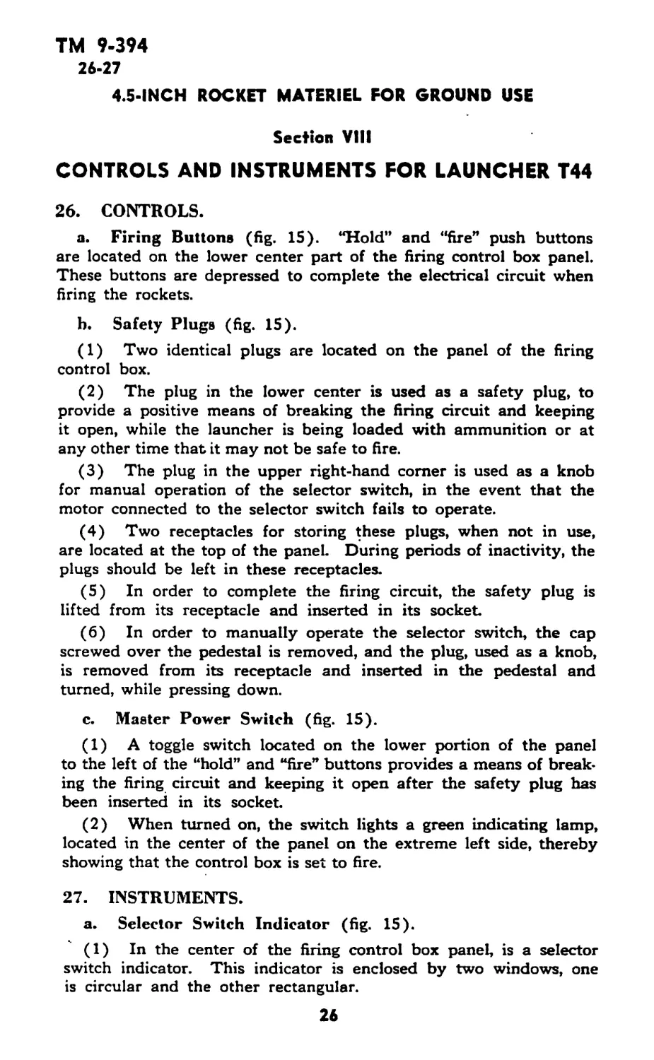
a. Firing Buttons (fig. 15). “Hold” and “fire” push buttons
are located on the lower center part of the firing control box panel.
These buttons are depressed to complete the electrical circuit when
Bring the rockets.
b. Safety Plugs (6g. 15).
(1) Two identical plugs are located on the panel of the Bring
control box.
(2) The plug in the lower center is used as a safety plug, to
provide a positive means of breaking the firing circuit and keeping
it open, while the launcher is being loaded with ammunition or at
any other time that it may not be safe to fire.
(3) The plug in the upper right-hand comer is used as a knob
for manual operation of the selector switch, in the event that the
motor connected to the selector switch fails to operate.
(4) Two receptacles for storing these plugs, when not in use,
are located at the top of the panel. During periods of inactivity, the
plugs should be left in these receptacles.
(5) In order to complete the firing circuit, the safety plug is
lifted from its receptacle and inserted in its socket.
(6) In order to manually operate the selector switch, the cap
screwed over the pedestal is removed, and the plug, used as a knob,
is removed from its receptacle and inserted in the pedestal and
turned, while pressing down.
c. Master Power Switch (fig. 15).
(1) A toggle switch located on the lower portion of the panel
to the left of the “hold” and “fire" buttons provides a means of break-
ing the firing circuit and keeping it open after the safety plug has
been inserted in its socket.
(2) When turned on, the switch lights a green indicating lamp,
located in the center of the panel on the extreme left side, thereby
showing that the control box is set to fire.
27. INSTRUMENTS.
a. Selector Switch Indicator (fig. 15).
(1) In the center of the firing control box panel, is a selector
switch indicator. This indicator is enclosed by two windows, one
is circular and the other rectangular.
26
TM 9-394
27-28
CONTROLS AND INSTRUMENTS FOR LAUNCHER T45
RECEPTACLES for holding
SAFETY plug and selector
SWITCH KNOB WHEN LID of
CONTROL BOX is CLOSED
safety plug
Е5НПШПЗ
KSC6 OPERATING
SELECTOR SWITCH MANUALLY
* CAP To BE SCREWED in
PLACE WHEN SELECTOR
ITCH KNOB IS REMOVED
CONTROL
push BUTTONS
INDICATING LAMP
SELECTOR SWITCH
MASTER POWER SWITCH
RA PD 9071b
Figure 15—Firing Control Box—Launcher T44
(2) The circular window houses two white arrows, each on its
own disk. During normal operation, these arrows rotate together so
as to point to each other. If they are not in line, indication is given
that the selector switch has been operated manually or otherwise
disturbed, since firing stopped.
(3) The rectangular window shows the position of the selector
switch and therefore the number of rockets fired.
Section IX
CONTROLS AND INSTRUMENTS FOR LAUNCHER T45
28. CONTROLS.
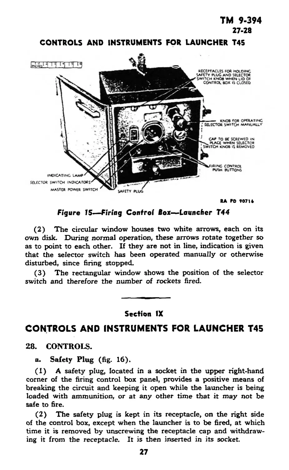
a. Safety Plug (fig. 16).
(1) A safety plug, located in a socket in the upper right-hand
corner of the firing control box panel, provides a positive means of
breaking the circuit and keeping it open while the launcher is being
loaded with ammunition, or at any other time that it may not be
safe to fire.
(2) The safety plug is kept in its receptacle, on the right side
of the control box, except when the launcher is to be fired, at which
time it is removed by unscrewing the receptacle cap and withdraw-
ing it from the receptacle. It is then inserted in its socket.
ТМ 9-394
28
4.S-INCH ROCKET MATERIEL FOR GROUND USE
RA PD 50511
Figure 16—-Firing Control Box—Launcher T45
b. Power Button (fig. 16).
(1) A power button, located on the lower left-hand corner of
the panel, provides a means of breaking or completing the electric
firing circuits after the safety plug has been inserted in its socket.
(2) The button is depressed to operate.
c. Firing Buttons (fig. 16).
(1) Two firing buttons, located on the panel to the right of the
power button, provide a means of completing the electric circuit to
the rockets, in order that they may be fired. Each button controls
a separate launcher.
(2) To operate, these buttons are depressed.
28
TM 9-394
29-30
OPERATION OF LAUNCHERS Ml2, M12A1. AND M12E2 UNDER
USUAL CONDITIONS
29. INSTRUMENTS.
a. Firing Pilot Light (fig. 16). A firing pilot light, located
in the upper left-hand corner of the control box, lights vhen the
power button is depressed, thereby showing that current is available
and the control box set to fire the rockets.
Section X
OPERATION OF LAUNCHERS Ml2. M12A1. AND M12E2
UNDER USUAL CONDITIONS
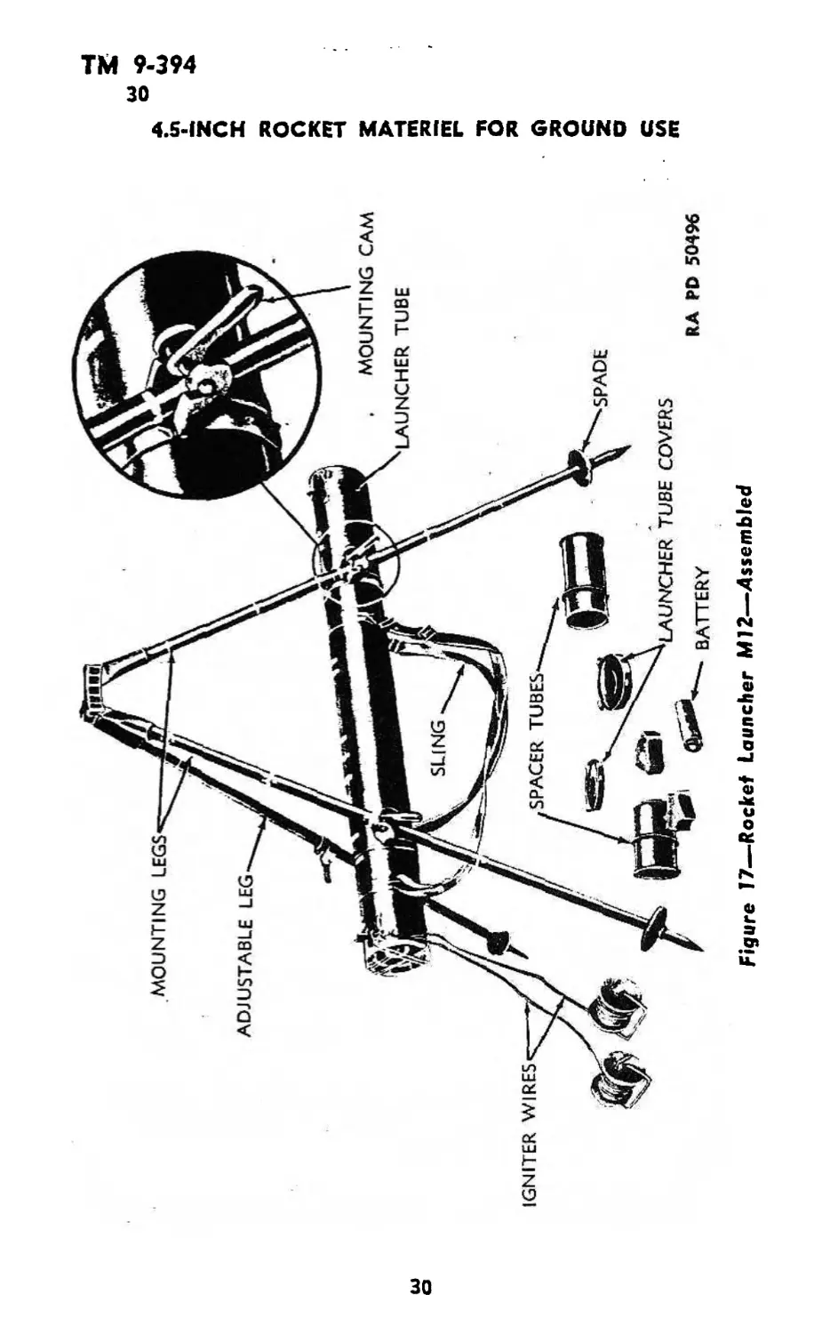
30. EMPLACEMENT (fig. 17)
a. Precautions.
(1) The muzzle of the launcher tube, when in firing position,
must be at least 12 inches away from all obstructions, such as the
ground, rocks, grass, branches, and so forth. When the Rocket M8
leaves the launcher, the fins open to a diameter of 12 inches and there-
fore a minimum clearance of at least 12 inches in diameter must be
provided for the passage of the rocket to the target. If the fins should
strike ground, leaves, branches and so forth, the rocket will be de-
flected from its course. .
(2) If it is necessary to move the launcher when the front or
rear end of the tube is open, be careful to maintain the launcher in
an approximately horizontal position, in order to prevent the rocket
from sliding out and breaking the igniter wires or causing a pre-
mature explosion.
(3) Make certain the rocket propelling charge is correct for the
atmospheric temperature. These adjustments must be made by
ordnance personnel as outlined in paragraph 122.
b. Place launcher, as issued, on ground with tripod facing upward.
c. Remove the two packing straps, taking care not to lose mount-
ing cams.
d. Set up tripod by spreading all three legs to a full position-
If the ground requires use of spades on the legs, remove the three
spades from the spacer inside the front of the launcher tube, and
slip one spade over the end of each leg.
e. Hang the packing straps, together with the mounting cams,
over top of the tripod and position the tripod so that the two mount-
ing legs are to the right of the firing position.
29
Ul
о
Figure 17—Rocket Launcher M12—Assembled
z
4.5-INCH ROCKET MATERIEL FOR GROUND USE
ТМ 9-394
30
OPERATION OF LAUNCHERS Ml 2. M12A1, AND M12E2 UNDER
USUAL CONDITIONS
f. Estimate approximately the height above the ground at which
the launcher will be emplaced. The maximum position is approxi-
mately 30 inches above the ground. A minimum clearance of at
least 12 inches in diameter must be provided for the passage of the
rocket to the target.
g. Release latch of front mounting support and slide the support
along the tube so that the support lines up between the pair of stripes
which correspond with the desired elevation. If the desired elevation
is less than 18 inches, the front support must be removed from the
tube and placed on the other side of the sling strap.
h. Line up white stripe on top of mounting support strap with
white line on top of launcher, and fasten mounting support latch.
i. Make sure that rear mounting support is positioned between
the last two stripes on the launcher tube in the same manner as the
front mounting support, and make sure that the latch is fastened.
j. Place launcher tube underneath tripod, holding it horizontal
and parallel to the mounting legs.
k. Grasp launcher tube at each end and raise it to the approxi-
mate elevation. Position the U-shaped pieces on mounting supports
around the mounting legs of the tripod and, while holding the
launcher tube in the center, take mounting cam from strap on top
of tripod, and insert each locking cam in support with the cam handle
upward and cam projection outward. Tighten the launcher tube in
place by rotating the cam downward.
1. Release cover latches and remove front and rear launcher tube
covers.
m. Remove front spacer from the launcher tube and withdraw
the battery from inside the spacer. Remove the three spades if not
previously removed.
n. Remove rear spacer carefully; withdraw the two spools of
wire from inside of spacer and place the spools of wire on the ground.
Be careful not to break the wire leading to the rocket. Make sure
launcher tube is clear except for rocket.
NOTE: On rocket launchers of present manufacture the wire is
wound around the outside of the rear spacer, which eliminates the
two spools.
o. Reach inside the rear of the launcher tube and push the
rocket forward until the fuze is exposed at the front end of the tube.
NOTE: If the rocket in the Launcher Ml2 has not been fuzed, as-
semble fuze as outlined in paragraph 124. For fuzing of rocket in
Launcher M12A1 or M12E2 see paragraph 15.
31
TM 9-394
30
4.5-INCH ROCKET MATERIEL FOR GROUND USE
RA PD 6520B
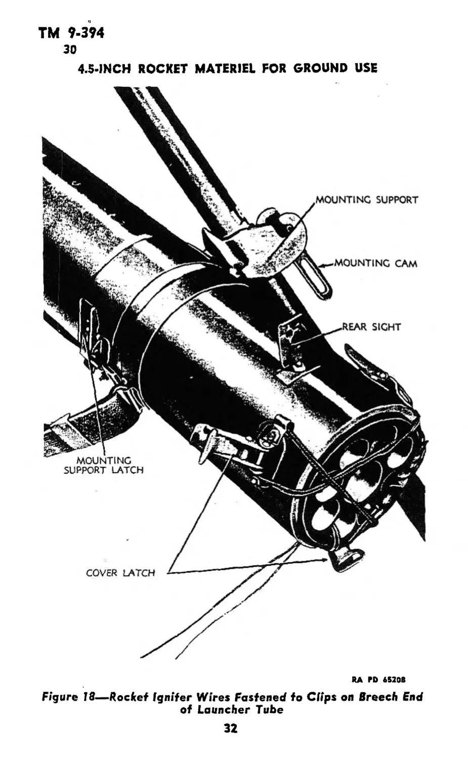
Figure 18—Rocket Igniter Wires Fastened to Clips on Breech End
of Launcher Tube
32
ТМ 9-394
30-31
OPERATION OF LAUNCHERS M12v M12A1. AND M12E2 UNDER
USUAL CONDITIONS
p. Set the fuze for the action required (delay or superquick),
paragraph 123 b or 127 a. Remove the safety pin from the fuze
(Launcher M12 only) and push the rocket back into the tube until
the rear end of the rocket is flush with the rear end of the tube.
NOTE: When pushing the rocket back into tube, do not push directly
on point of fuze.
q. Grasp the two rocket igniter wires (fig. 18) and hook them
under one of the clips attached to the rear cover latches; then draw
the two wires across the back open end of the launcher tube to the
next latch and hook in the clip; then bring the wires across to the
third latch; then back to the original clip. This will prevent the pro-
jectile from sliding out of the launcher tube before being fired.
r. Aim the launcher by sighting along the open sights or along
the white line painted on top of the tube. Turn the tripod to obtain
the proper direction. When using the rear peep sight, bend it per-
pendicular to the tube as shown in figure 40. Aim by centering the
front sight in the rear peep sight and at the same time alining the
front sight on the target.
e. Push the legs into the ground and set the adjustable leg so as
to obtain desired elevation of the launcher. NOTE: The position of
the launcher tube on the mounting legs, and the position of the ad-
justable leg provide variation in heights above the ground of both
tripod and tube.
t. Pick up the spools and reel out the wire while proceeding to the
firing position. Be sure to allow slack in order to prevent the tripod
from being tipped over.
31. EMPLACEMENT FOR FIRING SALVOS.
a. Up to three rockets may be fired in one salvo.
b. Embrace each launcher as described in the preceding para-
graph.
c. When setting up for salvo firing, do not place launchers closer
than fifteen feet. This is to prevent the blast of one rocket deflecting
neighboring rockets.
<L All rockets must be wired in parallel with the exploder ter-
minals, in order to fire a salvo. The wiring is done as follows:
(1) Draw the igniter wires from launcher which is furthest from
the exploder position, to the exploder position. If necessary, splice
additional wire to these lines.
(2) Strip insulation and splice one igniter wire from each of the
33
ТМ 9-394
31
4.5-INCH ROCKET MATERIEL FOR GROUND USE
34
ТМ 9-394
31-32
OPERATION OF LAUNCHERS Ml2. M12A1, AND M12E2 UNDER
USUAL CONDITIONS
other launchers in the salvo to one of the lines leading to the ex-
ploder position.
(3) Splice the other igniter -wire from each of the other launchers
to the second line leading to the exploder position. Figure 19 shows
the proper wiring for three launchers in a salvo.
(4) An alternate method of preparing this wiring is to connect
one wire from each of the launchers to one terminal of the exploder,
and to connect the other wire from each of the launchers to the other
terminal of the exploder. This can only be done when it is possible to
bring wires from all the launchers to the exploder position.
32. ELECTRICAL CONNECTIONS.
a. Important. Wires must be carefully and correctly spliced
(uninsulated portion of two or more connected wires) to insure the
passage of electricity from one wire to the others. Electricity may
not pass across a spliced connection if insulation, grease, or dirt is
present.
b. To Splice Wires.
(1) Remove the insulation from 3 to 4 inches of the ends of the
wires to be spliced. Be careful not to damage the wire when removing
the insulation. Scrape the bare ends lightly with a knife blade, being
careful not to damage the wire, to insure that all insulating material
is removed.
(2) Hold the bare sections of wire together and form a hairpin
bend in the center of the bare section, using a small rod or similar
toot (A pencil, the neck of a cal. .30 cartridge, or the handle of a
pair of pliers will be satisfactory.) (fig. 20A).
(3) Hold the wires firmly and twist into a loop with four or
five turns. Be sure the wires are tightly twisted (fig. 20B).
(4) Remove the twisting tool. Bend the insulated parts of the
wires into four legs so as to hold the splice off the ground. If a wire
has a free end at the splice, bend the end up (fig. 20C).
c. Handling Wire.
(1) Be careful not to kink or break wires.
(2) Be careful not to upset emplaced launchers while drawing
wires to the next launchers or to the exploder.
(3) Uninsulated wires must not come in contact with the ground.
Spliced joints may be held up by supporting, them on dry stones or
dry sticks.
(4) If raining, insulate the splices with tape.
(5) Do not allow a bare wire to touch the launcher legs.
3S
TM 9-394
32
4.5-INCH ROCKET MATERIEL FOR GROUND USE
Figure 20—Splicing Wires
36
RA PD 6S205
TM 9-394
33
OPERATION OF LAUNCHERS M12, M12A1. AND M12E2 UNDER
USUAL CONDITIONS
33. FIRING.
a. To Fire a Single Rocket With a Battery.
CAUTION: Make sure that all personnel are dear of the launchers
and at least 75 feet behind them. The position of the operator should
be to the side of the launcher and at least 50 feet away.
(1) Hold the bare end of one of the wires against the bottom of
the battery.
(2) To fire, touch the bare end of the other wire to the center
contact at the top of the battery.
b. To Fire a Single Rocket With an Exploder.
(1) Remove the firing handle if it has not been previously re-
moved.
(2) Make sure that terminals on exploder are clean and dry.
(3) Make sure that the lead wires to be connected to the ex-
ploder terminals have the insulation removed from their ends, and
are clean and dry.
(4) Connect the uninsulated end of one lead wire to one terminal
on the exploder, and the other wire to the other terminal. To do this,
loosen the nut on the terminal, hook or wind the clean and uninsulated
end of the lead wire around the binding post, and tighten the nut
down on the wire. Repeat with the other wire and other terminal.
(5) To fire, operate the exploder as follows:
(a) Hold the machine in the left hand, strap across the back of
hand.
(b) Insert the firing handle.
(c) Grasp the firing handle with the right hand, knuckles towards
terminals of machine, and twist the handle clockwise as rapidly as
possible while twisting the machine counterclockwise. Remove the
firing handle after firing the rocket.
c. To Fire a Salvo.
(1) Batteries which are issued with the launcher cannot be used
to fire a salvo.
(2) Check to be sure that all rockets to be fired in the salvo are
properly wired as described in paragraph 31.
(3) Connect to one exploder terminal the end of one of the lines
which carries half of the rocket igniter wires. Connection is to be
made as described in b (4) above.
(4) Connect to the other exploder terminal'the end of the other
line which carries the other half of the rocket igniter wires.
(5) To fire, operate the exploder as outlined in b (5) above.
37
ТМ 9-394
34-36
4.5- INCH ROCKET MATERIEL FOR GROUND USE
34. MISFIRES—LAUNCHER M12.
a. In the event that the rocket igniter explodes but the rocket
is not fired out of the launcher tube, disconnect the exploder or battery
and wait 10 minutes before approaching the launcher. Then remove
fhe rocket from the tube, insert the safety pin in the fuze, and return
the rocket and launcher to ordnance personnel for disposition.
3S. MISFIRES—LAUNCHERS M12A1 AND M12E2.
a. Proceed as in paragraph 34 above and in addition, after re-
moving the rocket from the tube, remove the fuze and return the
fuze, rocket, and launcher to ordnance personnel for disposition. The
fuze will be repacked and resealed in the fuze container, but the fuze
container will be kept separate and not replaced in the launcher.
Section XI
OPERATION OF LAUNCHERS T27 AND T27E1 UNDER
USUAL CONDITIONS
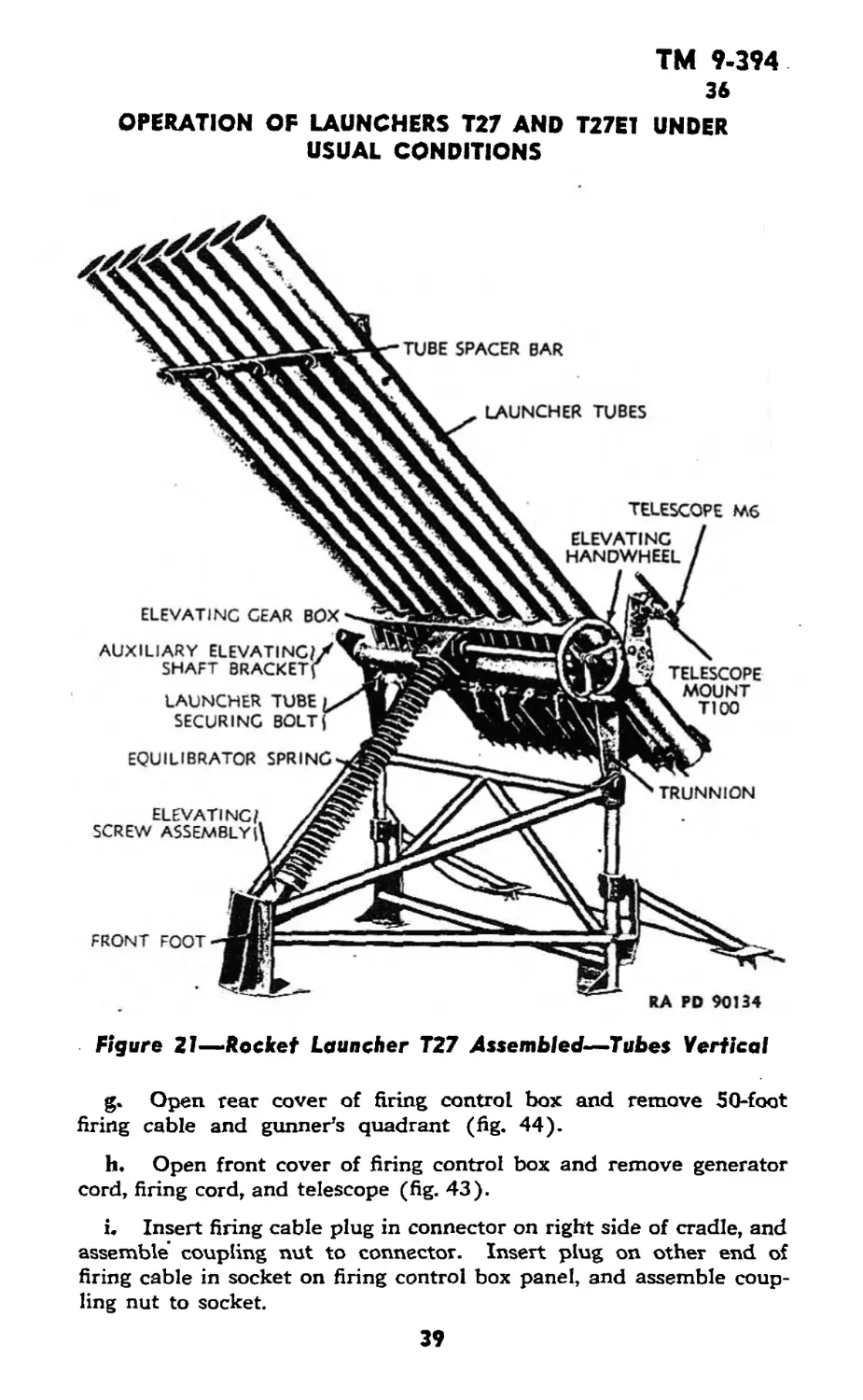
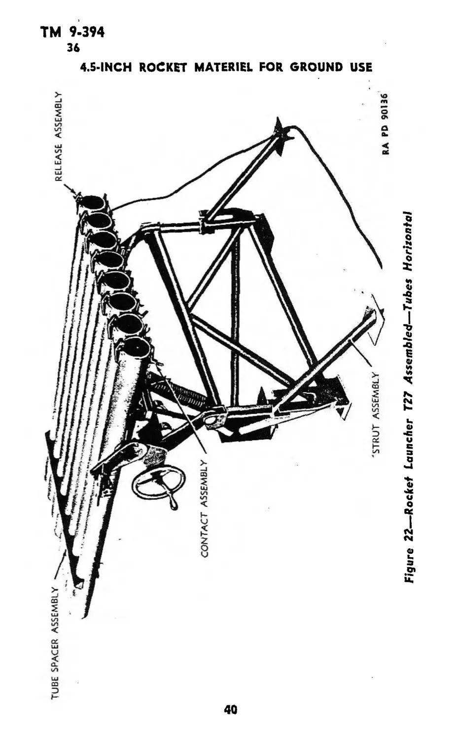
36. EMPLACEMENT OF LAUNCHER T27 (figs! 21 and 22).
&• Assemble the cradle assembly to the top rear of the mount by
inserting the trunnions in the brackets. Make sure the elevating
screw assembly is facing the front foot. Insert bolts through bracket
and trunnion, assemble and tighten nuts, and install cotter pin^.
b. Position the end of the elevating screw assembly in its bracket
on the front foot, insert bolt through bracket and elevating screw,
assemble and tighten nut, and install cotter pin.
c. Place the eight launcher tube assemblies in position on the
cradle and tighten the launcher tube securing bolts.
d. Place the tube spacer assembly in position on top of the tubes
approximately 18 inches from the front end so that the four bolts
protrude between the tubes.
e. Place tube spacer bar over the four bolts and assemble and
tighten thumb nuts.
L Loosen the four nuts on each strut clamp attached to the two
corner posts at the rear of the mount. Lift the struts up, swing them
around to the rear and position them in the U-brackets welded to
the rear corner posts. Tighten the four bolts on each clamp.
38
ТМ 9-394
36
OPERATION OF LAUNCHERS T27 AND T27E1 UNDER
USUAL CONDITIONS
Figure 21—-Rocket Launcher T27 Assembled—Tubes Vertical
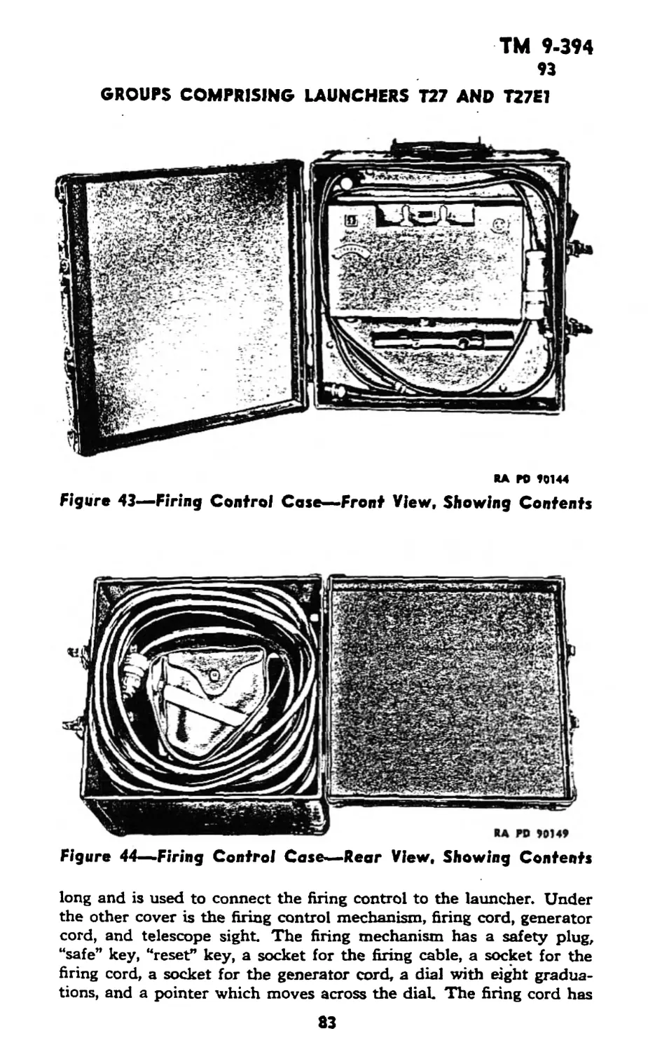
g. Open rear cover of firing control box and remove 50-foot
firing cable and gunner’s quadrant (fig. 44).
h. Open front cover of firing control box and remove generator
cord, firing cord, and telescope (fig. 43).
i. Insert firing cable plug in connector on right side of cradle, and
assemble’ coupling nut to connector. Insert plug on other end of
firing cable in socket on firing control box panel, and assemble coup-
ling nut to socket.
39
£
aH(lO«9 1101
TM 9-394
36-37
OPERATION OF LAUNCHERS T27 AND T27E1 UNDER
USUAL CONDITIONS
j. Insert plug on end of firing cord in socket marked “firing cord”
on control box panel, and assemble coupling nut to socket (fig. 23).
k. Insert plug on end of generator cord in socket marked “gen-
erator cord” on control box panel, and assemble coupling nut to socket
(fig. 23). Insert plug on other end in socket on back of generator.
This plug has an arrow which must be alined with arrow on generator
before plug can be inserted.
I. Remove generator handle from spring clips on front of gen-
erator and insert in socket on right side of generator (fig. 23).
m. Check dial on control box to make sure that dial pointer is
set at “0.” If not at zero, remove safety plug from its socket used for
storage and place it in socket marked “safety plug.” Move safe key
to “fire” position and check to see that reset key is in “reset” position.
Crank hand generator fast enough to light dial lamp. While cranking
generator, depress firing button in end of firing cord and dial pointer
will reset to “0.” Remove safety plug and replace safe key to “safe”
position.
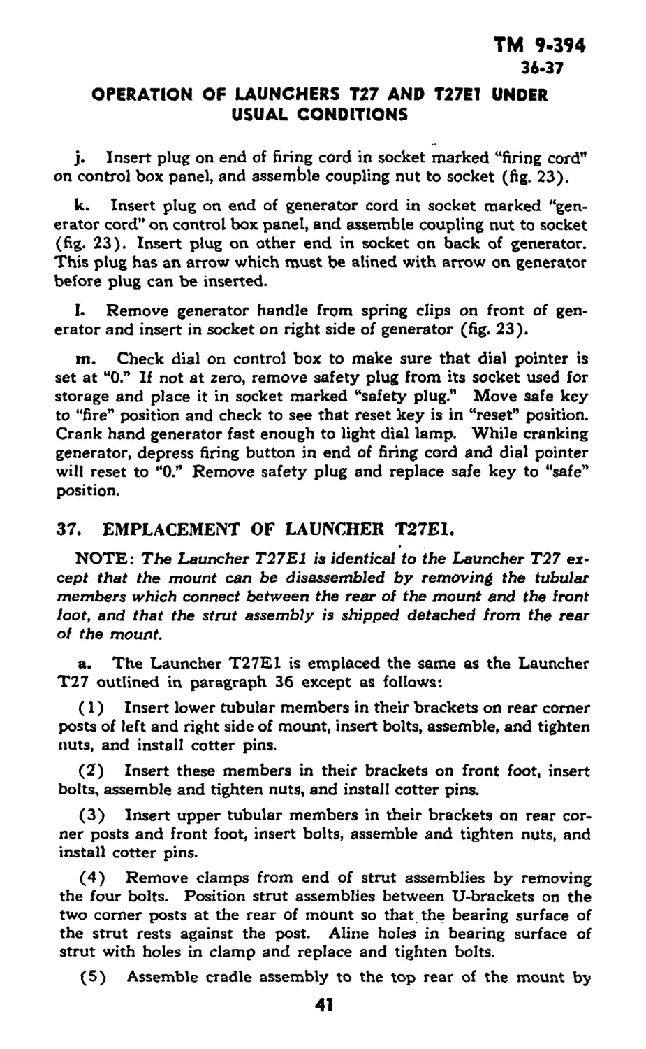
37. EMPLACEMENT OF LAUNCHER T27E1.
NOTE: The Launcher T27E1 is identical to the Launcher T27 ex-
cept that the mount can be disassembled by removing the tubular
members which connect between the rear of the mount and the front
foot, and that the strut assembly is shipped detached from the rear
of the mount.
a. The Launcher T27E1 is emplaced the same as the Launcher
T27 outlined in paragraph 36 except as follows:
(1) Insert lower tubular members in their brackets on rear comer
posts of left and right side of mount, insert bolts, assemble, and tighten
nuts, and install cotter pins.
(2) Insert these members in their brackets on front foot, insert
bolts, assemble and tighten nuts, and install cotter pins.
(3) Insert upper tubular members in their brackets on rear cor-
ner posts and front foot, insert bolts, assemble and tighten nuts, and
install cotter pins.
(4) Remove clamps from end of strut assemblies by removing
the four bolts. Position strut assemblies between U-brackets on the
two comer posts at the rear of mount so that the bearing surface of
the strut rests against the post. Aline holes in bearing surface of
strut with holes in clamp and replace and tighten bolts.
(5) Assemble cradle assembly to the top rear of the mount by
41
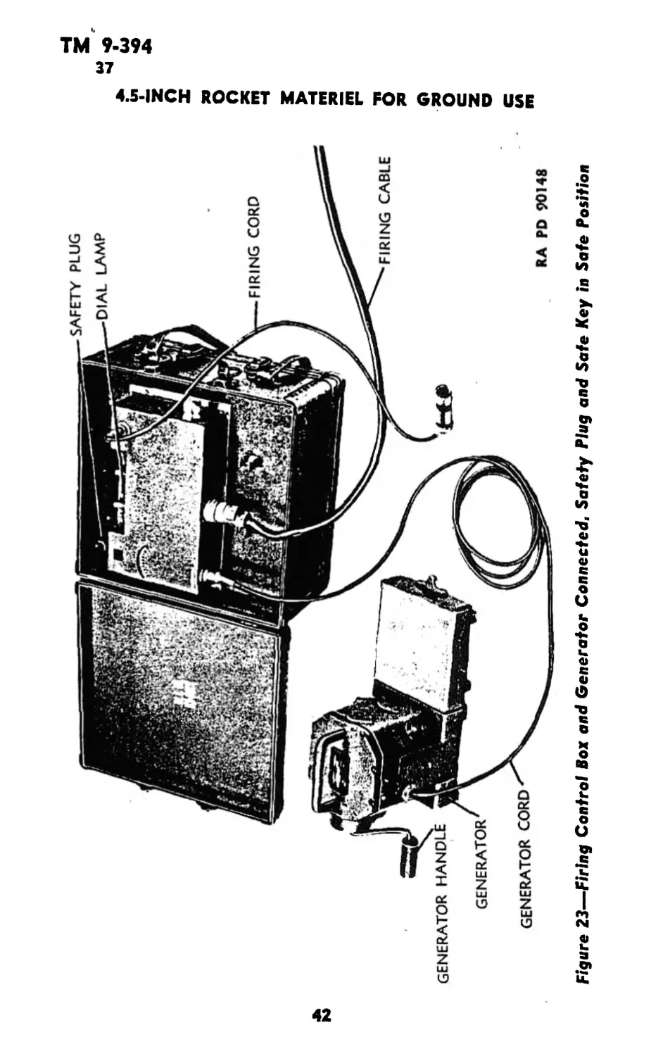
SAFETY PLUG
--DIAL LAMP
FIRING CORD
FIRING CABLE
GENERATOR HANDLI
GENERATOR
GENERATOR CORD
RA PD 90148
4.5-INCH ROCKET MATERIEL FOR GROUND USE
Figure 23—Firing Control Box and Generator Connected, Safety Plug and Safe Key in Safe Position
TM 9-394
37
OPERATION OF LAUNCHERS T27 AND T27E1 UNDER
USUAL CONDITIONS
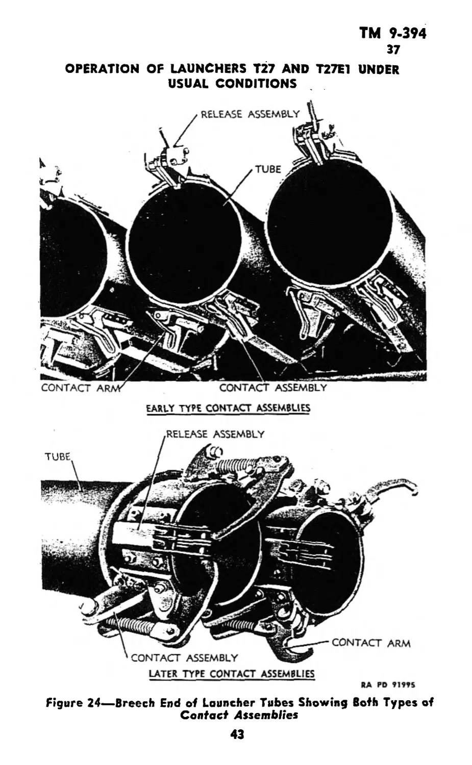
EARLY TYPE CONTACT ASSEMBLIES
LATER TYPE CONTACT ASSEMBLIES
ЙА pd
Figure 24—Breech End of Louncher Tubes Showing Both Types of
Contact Assemblies
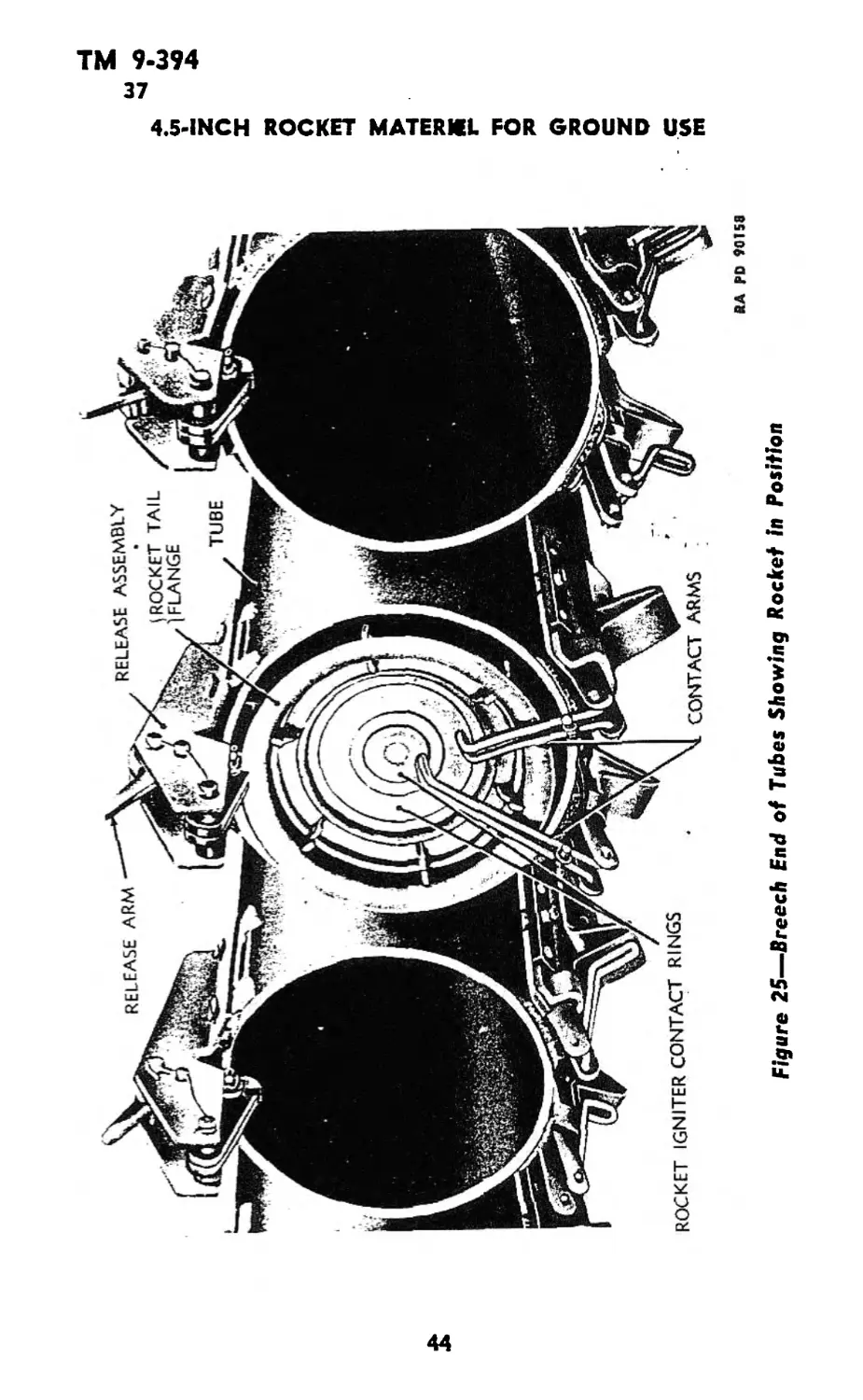
Figure 25—Breech End of Tubes Showing Rocket in Position
RA PD 90158
4.5-INCH ROCKET MATERIEL FOR GROUND USE
м
TM 9-394
37-39
OPERATION OF LAUNCHERS T27 AND T27E1 UNDER
USUAL CONDITIONS
inserting the trunnions in the brackets. Insert bolts, assemble and
tighten nuts, and install cotter pins.
(6) Position the elevating screw assembly in its bracket on the
front foot, insert bolt, assemble and tighten nuts and install cotter pin.
38. LOADING THE LAUNCHERS T27 AND T27E1.
a. Be sure the safety plug is removed from its socket in the firing
control box. This should be kept in the personal possession of the man
in direct charge of the loading crew until the loading operation is
finished.
b. Turn all electric contact arms to open position. These arms
should rest against the contact assembly attached to the rear out-
side of the launcher tubes (fig. 24).
c. Set rocket fuze as desired (SQ or delay) (par. 123 b) and
remove safety pin.
d. Insert rocket in each tube from the rear, making sure slot in
release latch engages the tail flange of the rocket (fig. 25). Remove
the fin retainer from the rear of each rocket if time permits. This is
not essential, but does eliminate the possibility of short-circuiting the
contact arms.
e. Turn the contact arms down onto the contacts of each rocket
igniter. Be sure tension is sufficient to insure good connections
(fig. 25).
CAUTION:. If the rocket has a percussion primer in addition to
the electric contact rings, do not let the contact arms snap down on
the rear of the rocket, as the long contact arm may strike the primer
and ignite the rocket, causing serious injury to personnel.
39. FIRING.
a. Make sure firing control box and hand generator are as far to
the side of the launcher as the firing cable will permit. Make certain
that personnel are out of range of the rearward blast of the rockets,
at least 75 feet to the rear of the point of emplacement.
b. Personnel firing the launcher should wear helmets.
c. Insert safety plug in socket marked “safety plug” on control
box panel (fig. 26).
d. Move safe key to “fire” position and move reset key to “fire”
position (fig. 26).
45
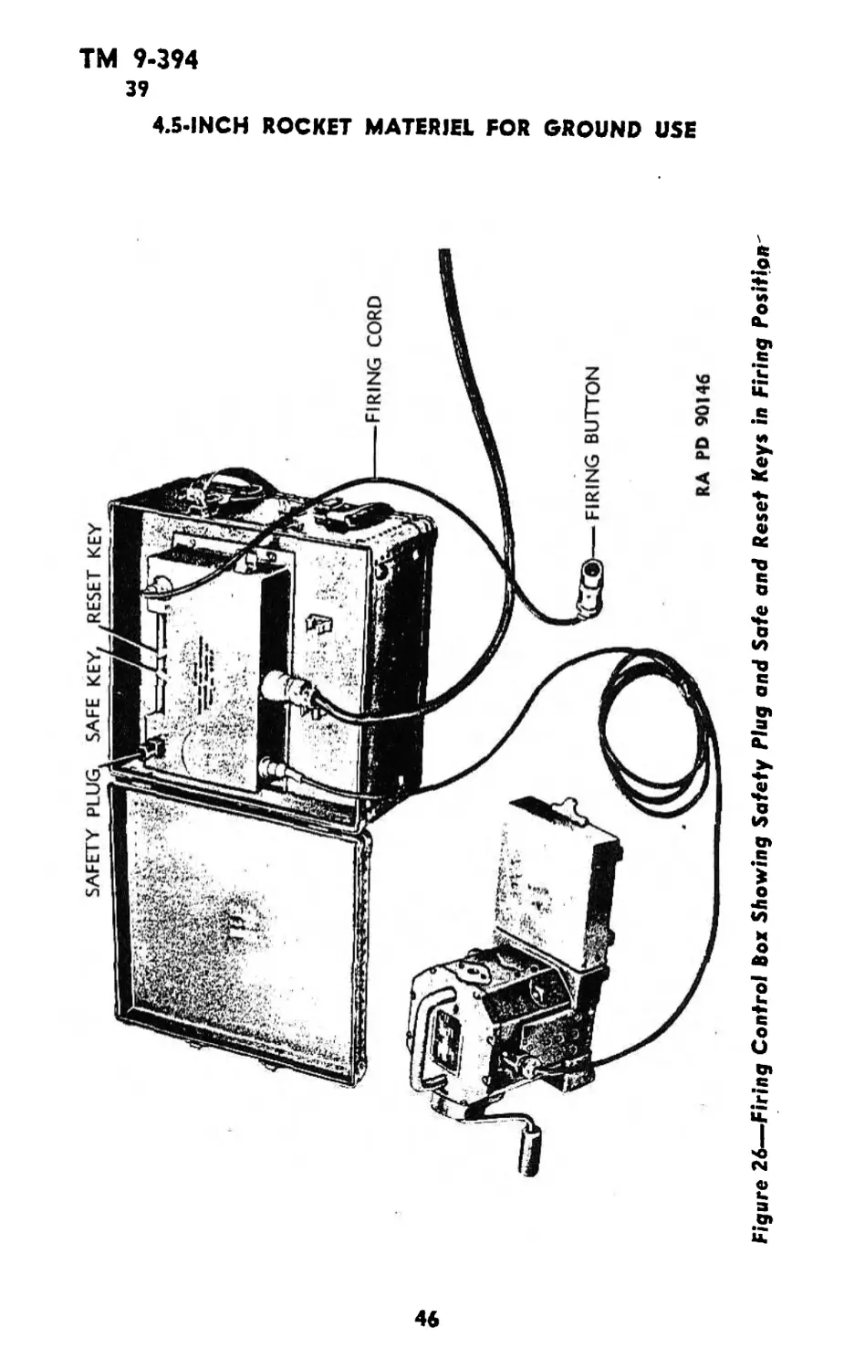
Figure 26—Firing Control Box Showing Safety Plug and Safe and Reset Keys in Firing Position'
4.5-INCH ROCKET MATERIEL FOR GROUND USE
SAFE KEY,
RESET KEY
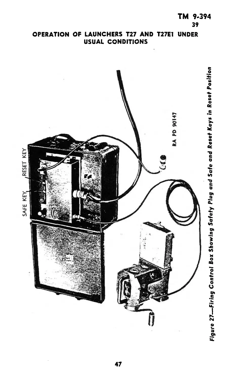
Figure 27-—Firing Control Box Showing Safety Plug and Safe and Reset Keys in Reset Position
TM 9-394
39-41
4.5-INCH ROCKET MATERIEL FOR GROUND USE
e. Crank hand generator with sufficient speed to illuminate red
dial lamp on control box panel.
f. While cranking generator, depress firing button in end of firing
cord (fig. 26). Rockets will then be discharged in proper sequence
and at approximately XA-second intervals until firing button is re-
leased or all rockets have been fired.
g. If it is desired to fire rockets singly, depress firing button while
generator is being cranked, and release immediately.
h. If it is desired to temporarily discontinue firing before all
rockets have been discharged, release firing button and move safe
key to “safe” position. Control of fire is then taken away from firing
button.
i. The firing control must be reset after all rockets have been
fired; however it can be reset before all rockets have been discharged,
so that, when the firing button is pressed again, the firing sequence
will start with No. 1 tube.
j. Reset firing control by moving reset key to "reset" position;
while cranking generator depress firing button (fig. 27).
k. Move fire key to “safe" position, remove safety plug from
“safety plug" socket and place it in socket used for storage.
40. UNLOADING.
a. Be sure safety plug is removed from its socket. This should
be kept in the personal possession of the person in direct charge of
the unloading crew until the operation is finished.
b. Turn all electric contact arms to open position.
c. Press down and hold release arm which disengages latch from
tail flange of rocket (fig. 25).
d. Withdraw rocket from the rear of the tube and replace safety
pin in the rocket fuze.
41. MISFIRES.
a. In the event that the rocket igniter explodes but the rocket
is not fired out of the launcher tube, remove the safety plug from the
firing control panel and wait 10 minutes before approaching the
launcher. Then remove the rocket from the launcher tube, insert the
safety pin in the fuze, and return the rocket to ordnance personnel
for disposition as a defective round.
48
TM 9-394
42-43
Section XII
OPERATION OF LAUNCHERS T34 AND T34E1 UNDER
USUAL CONDITIONS
NOTE: The Launchers T34 and T34E1 are issued mounted on the
Medium Tank M4 series with all necessary connections made.
42. LOADING.
a. Be sure safety plug is removed from its socket on left side of
firing control box (fig. 28). This should be kept in the personal pos-
session of the man in direct charge of the loading crew until the
loading operation is finished.
b. Turn all electric contact arms to open position. These arms
should rest against the contact assembly attached to the rear out-
side of the launcher tubes (fig. 29).
c. Set rocket fuze as desired (SQ or delay) (par. 123 b) and re-
move safety pin.
d. Insert rocket in each tube from the rear, making sure that
slot in release latch engages the tail flange of the rocket (fig. 30).
Remove the fin retainer from the rear of each rocket if time permits.
This is not essential, but does eliminate the possibility of short-
circuiting the contact arms.
e. Turn the contact arms down onto the contacts of each rocket
igniter. Be sure tension is sufficient to insure good connection (fig.
30). CAUTION: If the rocket has a percussion primer in addition
to the electric contact rings, do not let the contact' arms snap down
on the rear of the rocket, as long contact arm may strike the primer
and ignite the rocket, causing serious injury to personnel.
43. FIRING.
a. Close all doors and hatches on tank for protection of personnel.
b. Make sure friendly troops are at least 75 feet behind tank.
c. Insert safety plug in its socket on left side of control box.
d. Make necessary adjustments in elevation, using controls for
75-mm gun.
e. Make necessary adjustments in azimuth, using controls which
rotate the turret.
f. Move* safe and reset keys to “fire” position. The indicating
light will light, showing that the circuits are energized and ready for
firing (fig. 31).
49
&&&
SAFETY PLUG SOCKET
~lr
£/
RA PD 90153
Figure 28—Firing Control Box Without Safety Plug
50
TM 9-394
43
OPERATION OF LAUNCHERS T34 AND T34E1 UNDER
USUAL CONDITIONS
Figure 29-—Breech End of Launcher Tubes—Contact Arms In
Open Position
g. To fire single rockets press button in end of firing cord and
release immediately (fig. 31).
NOTE: The 75~mm gun should not be fired if a Launcher T34 is
mounted on the tank.
h. To discard rockets in ripple fire, press and hold button in end
of firing cord. Rockets will be discharged in proper sequence and at
approximately 0.5-second intervals as long as button is depressed or
until all rockets are fired. When button is released, firing is stopped.
i. When firing button is released to discontinue firing, move safe
key to “safe” position.
j. The firing control must be reset after all rockets have been
fired, however it can be reset before all rockets have been discharged,
so that, when the firing button is pressed again, the firing sequence
will start with No. 1 tube.
k. To reset firing control, move reset key to “reset” position and
safe key to "fire” position (fig. 32). The firing button need not be
51
ТМ 9-394
43-44
4.5-INCH ROCKET MATERIEL FOR GROUND USE
Figure 30—Breech End
RA PD 90156
of Launcher Tubes—Rocket in Position
for Firing
depressed. Firing control will automatically reset to zero with the
safe and reset keys in this position. Remove safety plug.
L The number of rockets fired is indicated on the selector switch
indicator dial located on the front of the control box (fig. 13).
m. After the firing control has been reset, turn the knob on the
circular window so that “0” alines with dial pointer. The dial pointer
remains stationary when the firing control is being reset.
44. UNLOADING.
a. Be sure safety plug is removed irom its socket. This should be
kept in the personal possession of the person in direct charge of the
unloading crew until the operation is finished.
b. Turn all electric contact arms to open position (fig. 29).
e. Press down and hold release arm which disengages latch from
tail flange of rocket (fig. 30).
d. Withdraw rocket from the rear of the tube and replace safety
pin in rocket fuze.
52
TM 9-394
44
OPERATION OF LAUNCHERS T34 AND T34E1 UNDER
USUAL CONDITIONS
RA PO 9014Z
Figure 31—Firing Control Box—Keys in Firing Position
RA PO 90140
Figure 32—-Firing Control Box—Keys in Reset Position
53
TM 9-394
45-46
4.5-INCH ROCKET MATERIEL FOR GROUND USE
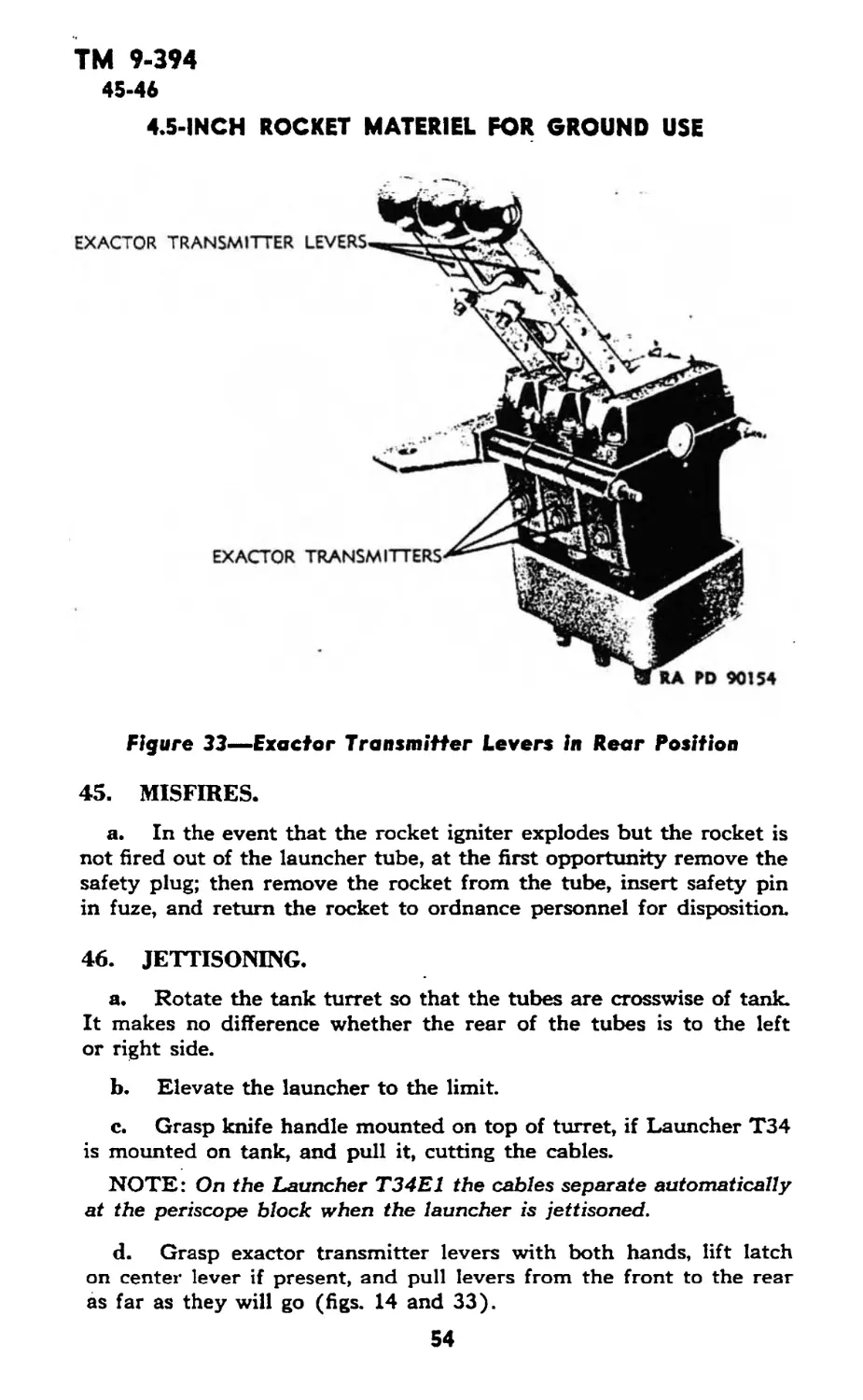
Figure 33—Exactor Transmitter Levers in Rear Position
45. MISFIRES.
a. In the event that the rocket igniter explodes but the rocket is
not fired out of the launcher tube, at the first opportunity remove the
safety plug; then remove the rocket from the tube, insert safety pin
in fuze, and return the rocket to ordnance personnel for disposition.
46. JETTISONING.
a. Rotate the tank turret so that the tubes are crosswise of tank.
It makes no difference whether the rear of the tubes is to the left
or right side.
b. Elevate the launcher to the limit.
c. Grasp knife handle mounted on top of turret, if Launcher T34
is mounted on tank, and pull it, cutting the cables.
NOTE: On the Launcher T34E1 the cables separate automatically
at the periscope block when the launcher is jettisoned.
d. Grasp exactor transmitter levers with both hands, lift latch
on center lever if present, and pull levers from the front to the rear
as far as they will go (figs. 14 and 33).
54
ТМ 9-394
47-48
Section XIII
OPERATION OF LAUNCHER T44 UNDER
USUAL CONDITIONS
NOTE: The Launcher T44 is issued mounted in the 2Уг-1оп, 6x6,
amphibian Truck, GMC, DUKW-353, or by use of the Harness
Adapter T2, in the Landing Vehicle, tracked (armored), Mk. IV, with
all necessary connections made.
47. OPERATIONS PRIOR TO LOADING.
a. Check the circular dial in the firing control box panel to make
sure that both arrows are in line (fig. IS). If they are not, line them
up as follows:
(1) Remove cap from pedestal in upper right-hand corner of the
firing control box panel.
(2) Remove selector switch manual knob (one of the safety
plugs) from its receptacle and insert it in the pedestal.
(3) Press down on the knob and turn it so as to move the outer
arrow until it comes in line with the inner arrow.
(4) Remove the knob, place it in its receptacle, and replace the
cap in the pedestal.
b. Set the selector switch indicator in the rectangular dial to
“0” or any other setting desired. This setting is done as follows:
(1) Operate the firing control box by depressing the “hold” and
“fire” buttons.
(2) Release the “fire’’ and “hold” buttons when “0”, or the number
before the one desired, comes opposite the red indicator mark.
NOTE: This setting should be made only when the wiring harness
is detached from the control box and before rockets are loaded into
the launcher.
e. Remove the two safety plugs from firing control box. These
should be kept in the personal possession of the person in direct charge
of the loading crew until the loading operation is finished.
d. Inspect and assemble the rockets (par. 125).
48. LOADING.
a. Stand on top of the launcher rack and to one side of the tube
to be loaded.
b. Remove the shorting clip from rocket shroud.
55
ТМ 9-394
48-49
4.5-INCH ROCKET MATERIEL FOR GROUND USE
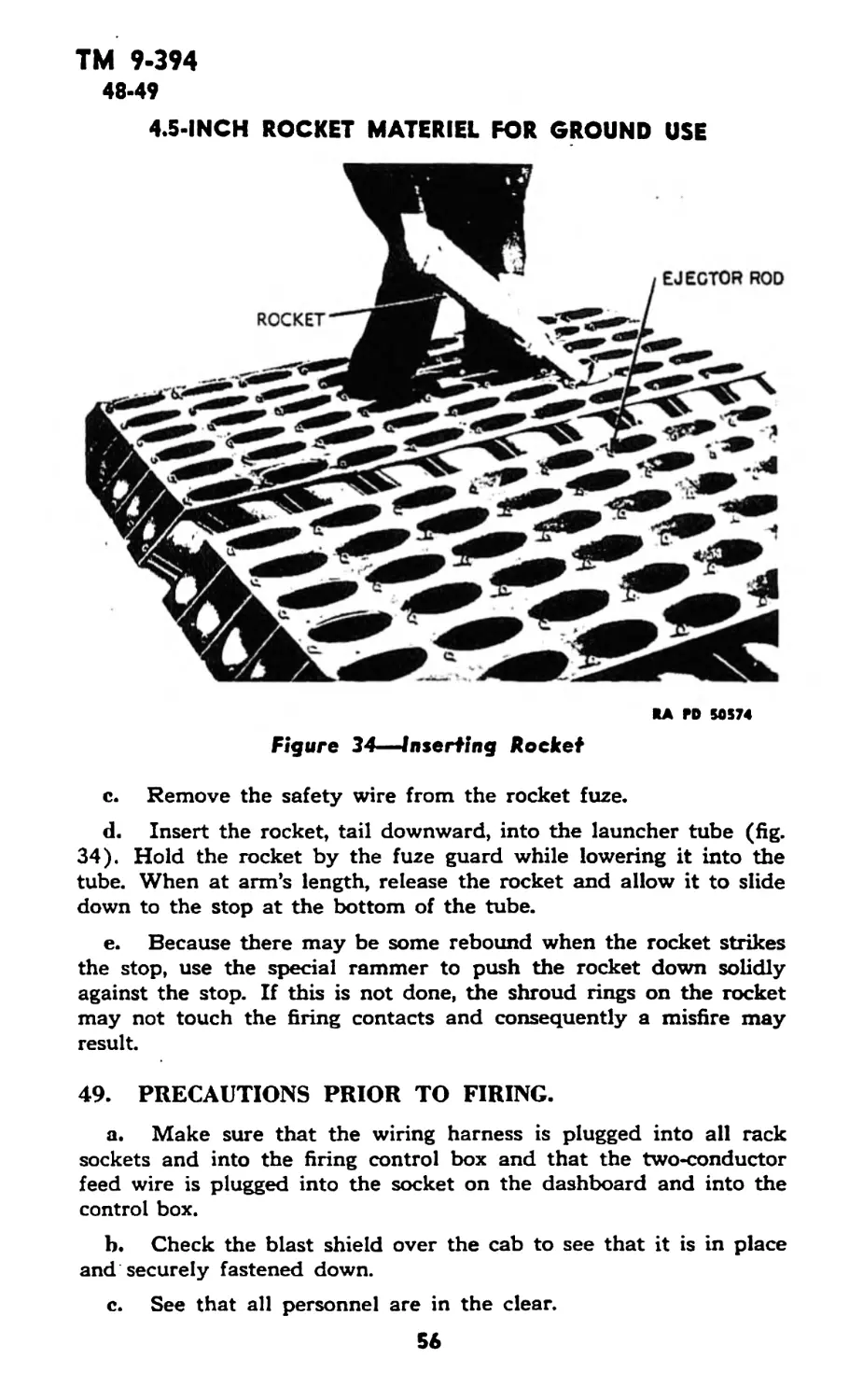
Figure 34—Inserting Rocket
SA PD 50574
c. Remove the safety wire from the rocket fuze.
d. Insert the rocket, tail downward, into the launcher tube (fig.
34). Hold the rocket by the fuze guard while lowering it into the
tube. When at arm’s length, release the rocket and allow it to slide
down to the stop at the bottom of the tube.
e. Because there may be some rebound when the rocket strikes
the stop, use the special rammer to push the rocket down solidly
against the stop. If this is not done, the shroud rings on the rocket
may not touch the firing contacts and consequently a misfire may
result.
49. PRECAUTIONS PRIOR TO FIRING.
a. Make sure that the wiring harness is plugged into all rack
sockets and into the firing control box and that the two-conductor
feed wire is plugged into the socket on the dashboard and into the
control box.
b. Check the blast shield over the cab to see that it is in place
and securely fastened down.
c. See that all personnel are in the clear.
56
TM 9-394
50
OPERATION OF LAUNCHER T44 UNDER USUAL CONDITIONS
50. FIRING.
a. Insert the safety plug in its socket in the raised panel of the
firing control box (fig. 15).
b. Turn on the master power switch. The indicating lamp will
light, showing that the circuits are energized and ready for firing
(fig. is).
c. When ready to fire, push down and hold the “hold” and
“fire” push buttons, using the index and middle fingers of the right
hand. The motor*driven selector switch will start and run as long
as the buttons are held down. This switch discharges current to the
firing circuits of successive launcher tubes at intervals of one-half
second, thus firing the rockets in ripple fire.
d. To cease firing, release the “fire” button by raising the index
finger, but hold the “hold" button a moment longer to permit the
electric braking circuit on the motor-driven switch to function. If
both push buttons are released together, the switch arm may coast
past the contact point connected to the next unfired rocket. Then
when firing is resumed, that rocket will be missed and remain unfired.
e. To fire a single rocket at a time, operate the “fire” button while
pressing the “hold” button.
f. If it is necessary to operate the selector switch manually,
proceed as follows:
(1 ) Remove the cap which screws to the pedestal in the upper
right-hand comer of the firing control box panel (fig. 15).
(2 ) Remove selector switch manual knob (one of the safety
plugs) from its receptacle and insert it in the pedestal.
(3 ) Depress “hold” and “fire” buttons with left hand.
(4 ) While holding these buttons depressed, push down on
selector switch knob and turn it slowly in a counterclockwise direction.
This turns the contact switch arm and dial in the same direction as
rotated by the motor. Firing speeds can be obtained which are ap-
proximately the same rate as obtained by the motor.
NOTE: When dial is turned by hand it will be noticed that the
arrow points, visible through round window, become displaced with
relation to each other. This condition is characteristic of hand opera-
tion and gives visual evidence that contact arm has been rotated from
last position to which it was brought by running the motor. This is
of particular importance in case firing has been stopped before all
rounds have been fired, because it definitely shows that the box has
been disturbed since firing stopped. The arrows should be reset to
aline them, so that firing would begin where it had left off and no
unfired rounds would be left in the launcher.
57
TM 9-394
51-53
4.5-INCH ROCKET MATERIEL FOR GROUND USE
51. UNLOADING.
a. Remove the safety plugs from the firing control box and
carry them until all ammunition has been unloaded from the launcher.
b. Insert the ejector hook in the eye of the ejector rod near the
muzzle of the tube to be unloaded.
c. Pull the ejector hook upward. The ejector rod can be pulled
up about 4 inches, which is sufficient to clear the rocket shroud rings
of the firing contacts.
d. Reach into the launcher tube, grasp the fuze guard, and pull
out the rocket.
e. Inspect fuze to make sure it is not armed.
f. Replace the fuze safety wire in the fuze.
g. Replace the shorting clip on the rocket shrouds.
52. MISFIRES.
a. If a misfire occurs, remove the round from the launcher at the
first opportunity, following the instructions given in paragraph 51.
Then make the following inspections:
(1) Inspect the rocket motor carefully to see whether the shorting
clip had been removed. If not, remove the clip to eliminate the
cause of misfire.
(2) Inspect the motor shroud rings for the scratch marks made
by the firing contacts. If clear marks do not show up on both shroud
rings, proper connection probably was not made; at the first oppor-
tunity, the contacts in the launcher tube should be inspected for pos-
sible damage by ordnance personnel.
( 3 ) If possible, an attempt may be made to fire the misfired rocket
from another tube of the launcher, in order to determine whether the
difficulty is due to a faulty rocket motor or to a fault in the firing
circuit of the tube.
Section XIV
OPERATION OF LAUNCHER T45 UNDER
USUAL CONDITIONS
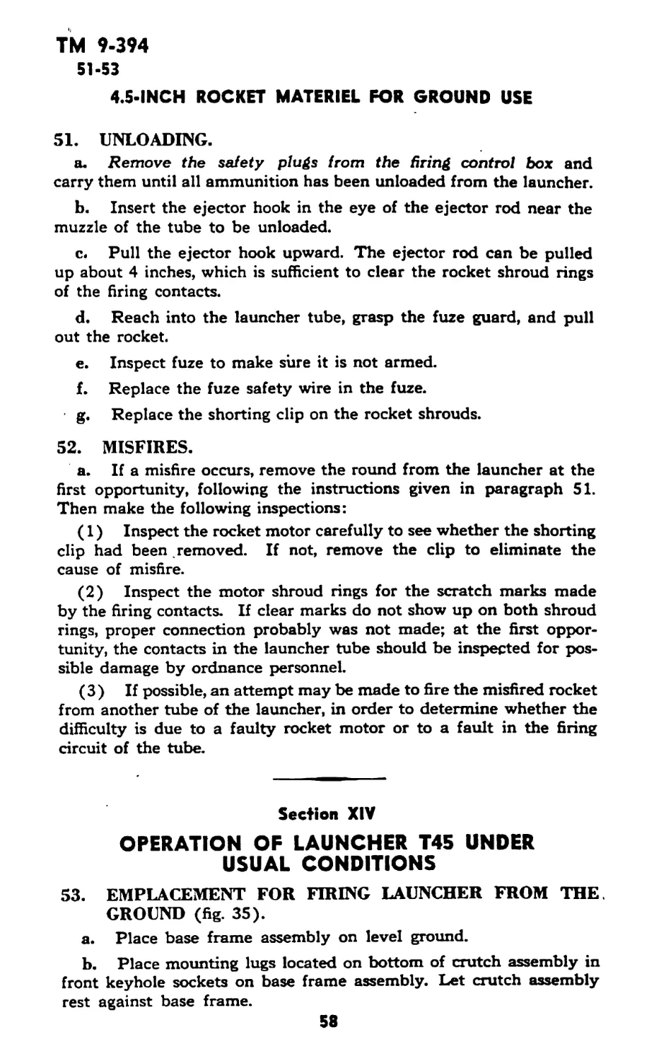
53. EMPLACEMENT FOR FIRING LAUNCHER FROM THE.
GROUND (fig. 35).
a. Place base frame assembly on level ground.
b. Place mounting lugs located on bottom of crutch assembly in
front keyhole sockets on base frame assembly. Let crutch assembly
rest against base frame.
58
TM 9-394
53
OPERATION OF LAUNCHER T45 UNDER USUAL CONDITIONS
SA ГО 50514
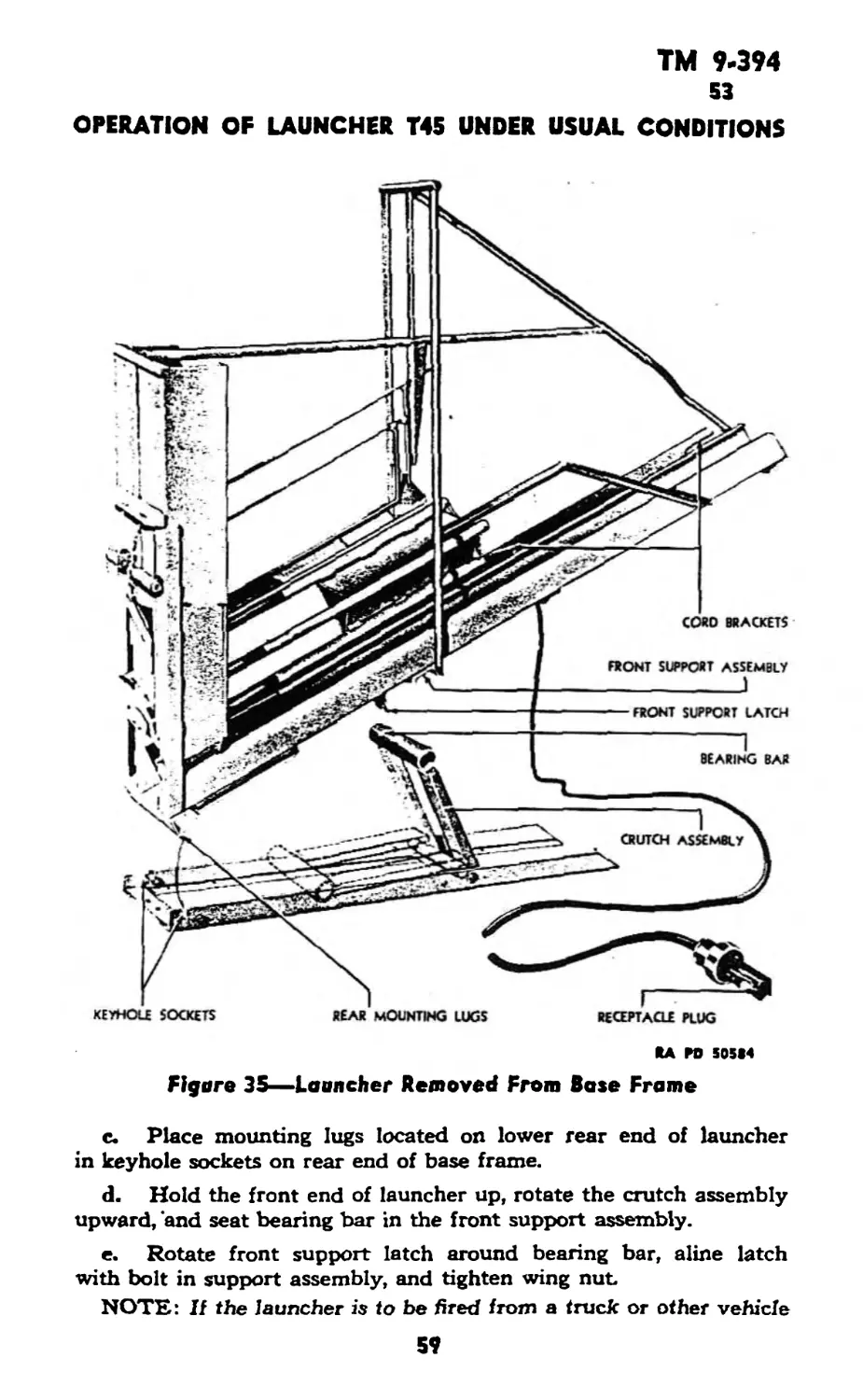
Figure 35—Launcher Removed From Base Frame
c. Place mounting lugs located on lower rear end of launcher
in keyhole sockets on rear end of base frame.
d. Hold the front end of launcher up, rotate the crutch assembly
upward, 'and seat bearing bar in the front support assembly.
e. Rotate front support latch around bearing bar, aline latch
with bolt in support assembly, and tighten wing nut.
NOTE: If the launcher is to be fired from a truck or other vehicle
59
ТМ 9-394
53-54
4.5-INCH ROCKET MATERIEL FOR GROUND USE
RA PD 50510
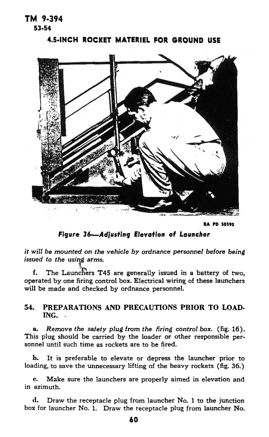
Elevation of Launcher
Figure 36—Adjusting
it will be mounted on the vehicle by ordnance personnel before being
issued to the using arms.
чг_
f. The Launchers T45 are generally issued in a battery of two,
operated by one firing control box. Electrical wiring of these launchers
will be made and checked by ordnance personnel.
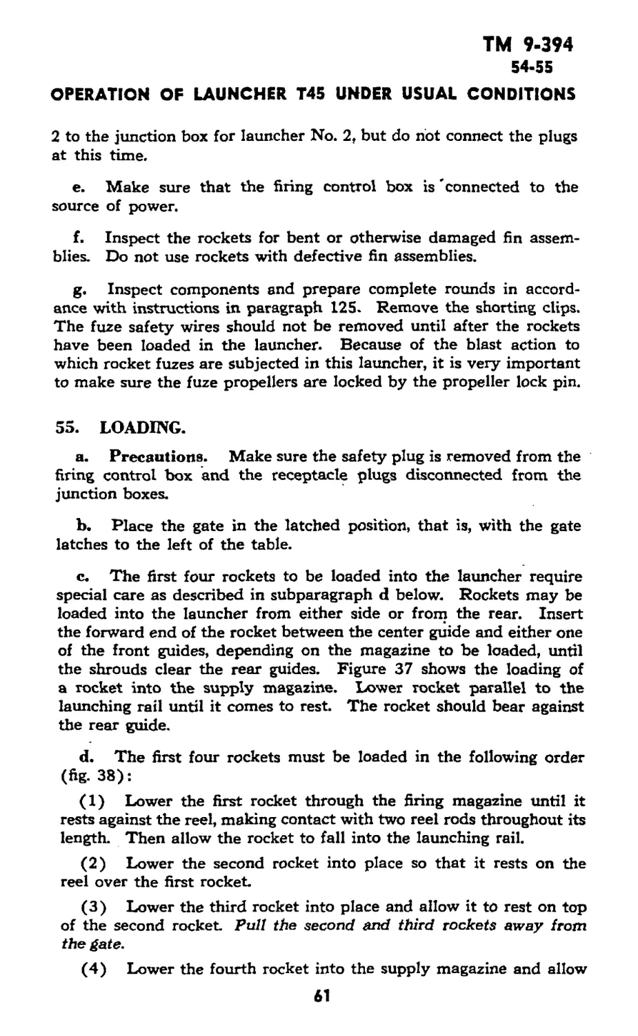
54. PREPARATIONS AND PRECAUTIONS PRIOR TO LOAD-
ING.
a. Remove the safety plug from the firing control box. (fig. 16).
This plug should be carried by the loader or other responsible per-
sonnel until such time as rockets are to be fired.
b. It is preferable to elevate or depress the launcher prior to
loading, to save the unnecessary lifting of the heavy rockets (fig. 36.)
c. Make sure the launchers are properly aimed in elevation and
in azimuth.
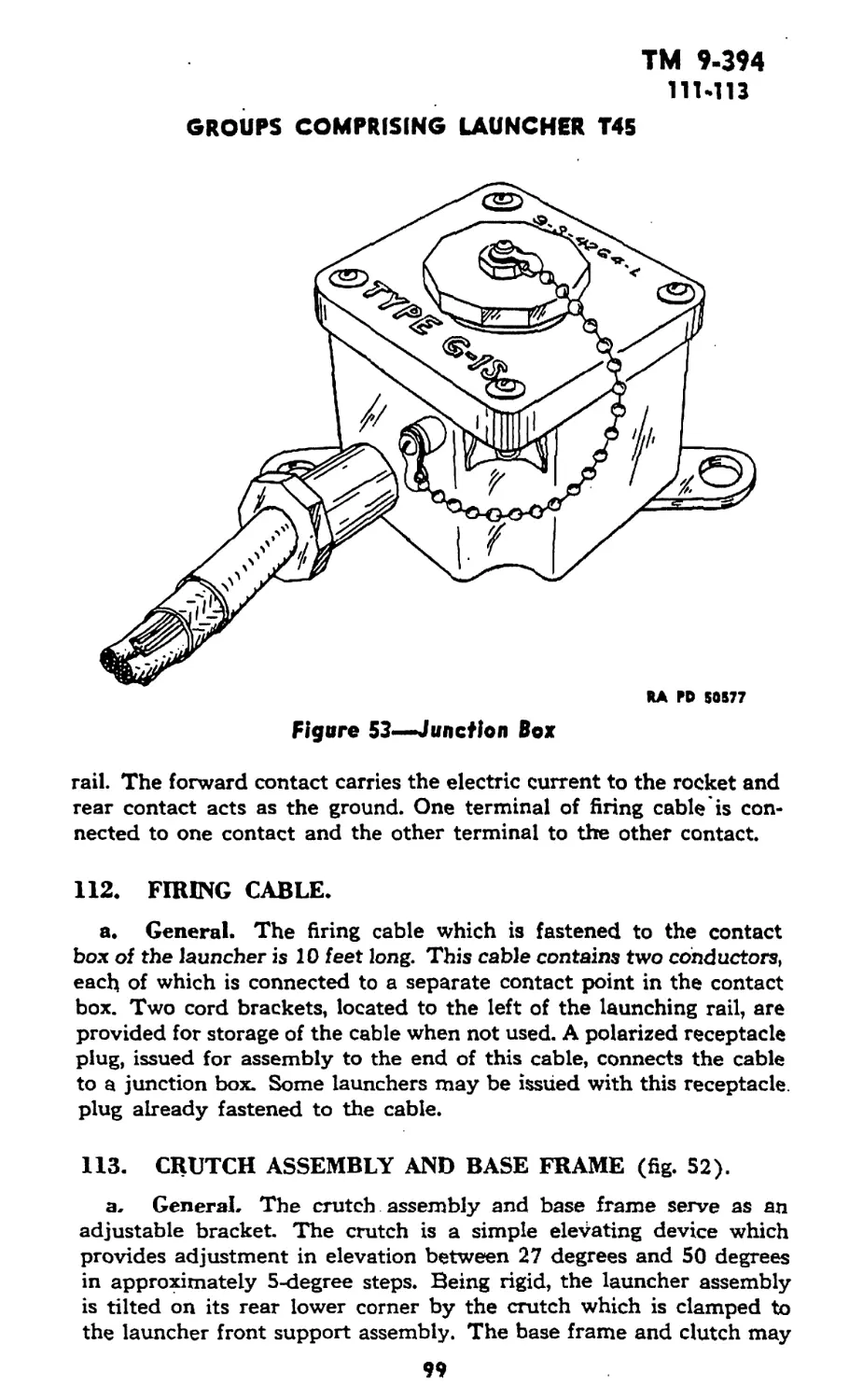
<1. Draw the receptacle plug from launcher No. 1 to the junction
box for launcher No. 1. Draw the receptacle plug from launcher No.
60
TM 9-394
54-55
OPERATION OF LAUNCHER T45 UNDER USUAL CONDITIONS
2 to the junction box for launcher No. 2, but do riot connect the plugs
at this time.
e. Make sure that the firing control box is 'connected to the
source of power.
f. Inspect the rockets for bent or otherwise damaged fin assem-
blies. Do not use rockets with defective fin assemblies.
g. Inspect components and prepare complete rounds in accord-
ance with instructions in paragraph 125. Remove the shorting clips.
The fuze safety wires should not be removed until after the rockets
have been loaded in the launcher. Because of the blast action to
which rocket fuzes are subjected in this launcher, it is very important
to make sure the fuze propellers are locked by the propeller lock pin.
55. LOADING.
a. Precautions. Make sure the safety plug is removed from the
firing control box and the receptacle plugs disconnected from the
junction boxes.
b. Place the gate in the latched position, that is, with the gate
latches to the left of the table.
c. The first four rockets to be loaded into the launcher require
special care as described in subparagraph d below. Rockets may be
loaded into the launcher from either side or from the rear. Insert
the forward end of the rocket between the center guide and either one
of the front guides, depending on the magazine to be loaded, until
the shrouds clear the rear guides. Figure 37 shows the loading of
a rocket into the supply magazine. Lower rocket parallel to the
launching rail until it comes to rest The rocket should bear against
the rear guide.
d. The first four rockets must be loaded in the following order
(fig. 38):
(1) Lower the first rocket through the firing magazine until it
rests against the reel, making contact with two reel rods throughout its
length. Then allow the rocket to fall into the launching rail.
(2) Lower the second rocket into place so that it rests on the
reel over the first rocket.
(3) Lower the third rocket into place and allow it to rest on top
of the second rocket. Pull the second and third rockets away from
the gate.
(4) Lower the fourth rocket into the supply magazine and allow
61
TM 9-394
55
4.5-INCH ROCKET MATERIEL FOR GROUND USE
Figure 37— Loading Launcher
it to rest on the table. After this, rounds may be loaded in any order.
The launcher is fully loaded when one rocket is in the launching rail,
six rockets above the reel, and five rockets above the table.
(5) Make sure that the rear edges of the shrouds are back against
the rear guide in each magazine.
62
TM 9-394
56-57
OPERATION OF LAUNCHER T45 UNDER USUAL CONDITIONS
RA PO 50592
Figure 38—Sequence for Loading Launcher
56. PREPARATION PRIOR TO FIRING.
a. Remove safety wires from rocket fuzes.
b. Connect receptacle plugs from launchers to their respective
junction boxes.
c. Make sure that no personnel are within 75 feet of the rear of
the launchers.
d.- Do not fire rockets below -|-10oF or above -J-120°F.
e. Personnel in vicinity of firing should wear helmets.
57. FIRING.
a. Place the safety plug in its receptacle in the firing control
box (fig. 16).
b. Hold the power button down. The firing pilot light should
light, indicating electric power is available (fig. 16).
c. To fire launcher No. 1, press firing button No. 1, and to fire
launcher No. 2, press firing button No. 2, while holding the power
button in the depressed position.
63
ТМ 9-394
57-59
4.5-INCH ROCKET MATERIEL FOR GROUND USE
d. To stop firing, release the firing buttons and the power button.
,e. Ripple fire will be obtained by holding the buttons down.
Single-action fire will be obtained by depressing the firing buttons
momentarily while holding the power button down.
f. As soon as firing is completed, remove the safety plug from
the firing control box, whether or not all rockets have been fired.
58. MISFIRES.
a. Should a jam occur as a rocket is feeding from the magazine
through the reel, it can usually be quickly corrected without unload-
ing by prying up on the forward end of the rocket caught in the reel.
Remove safety plug first,
b. In case a misfire occurs, attempt to fire by releasing and press-
ing power and firing buttons. If the misfire persists, wait 10 minutes
before proceeding with the instructions below.
(1) Check to make sure that the shorting clips have been re-
moved, that the shrouds of the rocket in the launching rail are not
bent, and that the knife edge contacts in the launcher make contact
with the shrouds. These contacts should cut through the paint on the
shrouds and come into contact wtih the metal of the shrouds.
(2) Inspect the closure disk in the rear of the rocket. If it has
blown out, the rocket is defective.
(3) If the rocket closure disk is intact, unload the launcher -as
described in the next paragraph, replace safety wire in fuze, and re-
turn the rocket, which would not fire, to ordnance personnel as a de-
fective round.
59. UNLOADING.
a. Precaution. Make sure that the safety plug is removed
from the firing control box and that the receptacle plugs are discon-
nected from the junction boxes.
b. Replace the shorting clips on the rocket shrouds.
c. Replace the fuze safety wires in the rocket fuzes.
d. Lift the rockets out of the supply magazine, one at a time.
e. Lift the rockets out of the firing magazine, one at a time, ex-
cept the rocket on the launching rail. This rocket should be removed
last by sliding it forward on the launching rail until it clears the reel,
then lifting it out
M
ТМ 9-394
60-63
Section XV
OPERATION UNDER UNUSUAL CONDITIONS
60. GENERAL.
a. Since rockets may not be fired outside their temperature
ranges, operation under extreme temperature conditions is not per-
mitted.
61. EXCESSIVELY MOIST OR SALTY ATMOSPHERE.
a. When the materiel is not in active use, the unpainted metal
parts should be covered with a film of rust-preventive compound
(light). The bore of the metal tubes should be kept oiled and all
parts should be inspected daily for traces of the formation of rust
The* materiel should be kept covered with tarpaulins as much as
possible.
b. In excessively salty atmosphere, the oil or rust-preventive
compound (light) used should be changed often as the salt has a
tendency to emulsify the oil and destroy its rust-preventive qualities.
c. Check mounts frequently for chipped or cracked paint.
62. EXCESSIVELY SANDY OR DUSTY CONDITIONS.
a. If considerable sand or dust is present when the launchers are
operated, the lubricant should be removed from the moving parts and
these parts should remain dry until the action is over. If the surfaces
are dry, there is less wear than when coated’ with a lubricant con-
taminated with grit.
b. Keep materiel covered with tarpaulins as much as possible.
c. Materiel must be cleaned frequently, as sand or dust and lubri-
cant act as an abrasive.
63. COLD CLIMATES WITHIN TEMPERATURE RANGES.
a. Preparing a weapon for cold climate consists of inspecting and
placing the launcher in good mechanical condition, cleaning, and
lubricating with cold weather lubricants, and frequent exercising.
b. The materiel should be inspected to see that all moving parts
operate freely and without binding.
c. In cold climates it is essential that all moving parts be kept
absolutely free of moisture.
d. Clean and lubricate all parts, but do not use excess lubricant,
because it may solidify to such an extent as to cause sluggish move-
ment.
65
ТМ 9-394
63-65
4.5-INCH ROCKET MATERIEL FOR GROUND USE
e. When launchers are in the open, cover with tarpaulins or
other suitable material, if possible.
f. When launcher and mount are transferred from the outside
into a heated building, wipe dry with clean cloths and clean and oil
metal parts immediately, to prevent condensation of moisture.
g. Before applying the cold weather lubricants, the materiel
should be thoroughly cleaned and all old lubricants removed.
64. HOT CLIMATE WITHIN TEMPERATURE RANGES.
a. In hot climates, inspect and clean the launcher as frequently
as retired, rather than at fixed intervals.
b. Where humidity is high, clean and oil as soon as possible after
firing, when the launcher gets wet or dirty, or if there is any reason
to expect corrosion to start.
c. In temperatures above 90° F, summer grade greases and oils
should be used as lubricants.
Section XVI
DEMOLITION TO PREVENT ENEMY USE
65. GENERAL.
a. The destruction of the materiel when subject to capture or
abandonment in the combat zone will be undertaken by the using
arm only on authority delegated by the division or higher commander,
as a command function when such action is deemed necessary as a
final resort to keep the materiel from reaching enemy hands.
b. Adequate destruction of rocket materiel means damaging it
in such a way that the enemy cannot restore it to usable condition
in the combat zone, by repair or cannibalization. Adequate destruc-
tion requires that:
(1) Enough parts essential to the operation of the materiel must
be damaged.
(2) Parts must be damaged beyond repair in the combat zone.
(3) The same parts must be destroyed on all materiel, so that
the enemy cannot make up one operating unit by assembling parts
from several partly destroyed units.
c. The tubes and firing control box are the most vital parts of
the 4.5-inch rocket launchers.
66
TM 9.394
66-70
DEMOLITION TO PREVENT ENEMY USE
66. DEMOLITION OF LAUNCHERS M12, M12A1, AND M12E2.
a. Since both of these launchers are issued equipped with rockets,
demolition should be as directed for ammunition in TM 9-1901.
67. DEMOLITION OF LAUNCHERS T27 AND T27E1.
a. Detach the sight If evacuation is possible, carry the sight If
not, smash the sight thoroughly. .
b. Remove safety plug and smash it, using butt end of rifle. Fire
a few rounds of caL -30 ammunition into the Are control box to destroy
it
c. Insert one Incendiary Grenade M14 midway in the center tube
at 0-degree elevation. Ignite this grenade by inserting one other
grenade, equipped with a 15-second safety fuze. Take cover, as the
danger zone is at least 100 yards.
68. DEMOLITION OF LAUNCHERS T34 AND T34E1.
a. Thoroughly smash firing control box, using any available
heavy tool in tank.
b. Jettison the launcher and drive over it with.the tank crushing
the tubes.
69. DEMOLITION OF LAUNCHER T44.
a. Thoroughly smash firing control box, using any available heavy
tool from the DUKW or LVT.
b. Insert one Incendiary Grenade M14 in approximately the
center tube of the fourth and eighth rack assembly. Ignite these
grenades by inserting one other grenade equipped with a 15-second
safety fuze in each tube. Take cover, as the danger zone is at least
100 yards.
70. DEMOLITION OF LAUNCHER T45.
a. Thoroughly smash firing control box, using any available heavy
tool from the truck or LVT, or, if mounted on the ground, by firing
a few rounds of cat Л0 ammunition into it.
b. Using a heavy tool, smash the knife-edge contacts and the con-
tact box.
c. Smash or deform the reel and gate.
67
TM 9-394
71-72
4.5- INCH ROCKET MATERIEL FOR GROUND USE
PART THREE—MAINTENANCE INSTRUCTIONS
Section XVII
GENERAL
71. SCOPE.
a. Part three contains information for the guidance of the per-
sonnel of the using organizations responsible for the maintenance
(1st and 2nd echelon) of this equipment. It contains information
needed for the performance of the scheduled lubrication and pre-
ventive maintenance services, as well as description of the major
systems and units and their functions in relation to other components
of the equipment.
Section XVIII
PREVENTIVE MAINTENANCE SERVICE
72. GENERAL.
a. Scope. Preventive maintenance services prescribed by army
regulations are a function of using organization echelons of mainte-
nance. This section contains preventive maintenance service allocated
to crew and scheduled preventive maintenance service allocated to
organizational maintenance.
b. Materials.
BURLAP, jute
CLOTH, wiping, cotton
COMPOUND, rust-preventive,
light
ENAMEL, synthetic, olive-drab,
lusterless
OIL, lubricating, preservative,
light
OIL, lubricating, preservative,
special
SOAP, government issue
SODA ASH
SOLVENT, dry-cleaning
c. Dirt or grit, accumulated in traveling or from blast of piece in
firing, settles on bearing surfaces and forms a cutting compound.
Powder fouling attracts moisture and settles in operating grooves,
preventing proper operation of moving parts, and hastens the forma-
tion of rust. It is essential that all parts be cleaned at frequent inter-
vals, depending upon use and service.
d. If rust should accumulate, its removal from bearing surfaces
requires special care in order that clearances shall not be unduly in-
68
ТМ 9-394
72-74
PREVENTIVE MAINTENANCE SCHEDULES
creased. Crocus cloth should be used for this purpose. The use of
coarse abrasives is strictly forbidden.
e. When materiel is not in use, suitable tarpaulins should be used
as covers.
f. When materiel is not to be used for considerable time, all
bright unpainted metal surfaces should be cleaned with dry-cleaning
solvent and coated with rust-preventive compound.
Section XIX
PREVENTIVE MAINTENANCE SCHEDULES
73. LAUNCHERS M12, M12A1, AND M12E2.
a. As these launchers are expendable and should be discarded
after the one round packed in the tube is fired, no maintenance is
necessary.
74. LAUNCHERS T27 AND T27E1.
a. Before Firing. Before firing remove all rust-preventive com-
pound from the release assembly and contact arms, using dry-clean-
ing solvent and clean dry burlap or wiping cloths. Before loading,
wipe the tubes with clean, dry burlap or wiping cloths to insure that
the tubes are clean and dry.
b. After Firing.
(1) After firing, swab the inside of the tubes to insure complete
removal of powder residue and primer salts. Under no circumstances
will the launcher remain without cleaning after it has been fired.
Swab the tubes with a cleaning solution of one-half pound of soda ash
to each gallon of water. Rinse with clean warm water. After drying
thoroughly with jute burlap, apply a film of special preservative
lubricating oil. If soda ash is not available, a soap sponging solution
may be prepared by dissolving 1 pound of government issue soap in
4 gallons of water. The soap should be shaved from the bar to
facilitate dissolving. It should then be added to water and the water
heated until the soap is dissolved. The water should be stirred as
quietly as possible to prevent foaming. To avoid the necessity of
handling large receptacles, as much soap as & required for all the
water to be used can be dissolved in one pail of water. This concen-
trated soap solution can then be added to water in other receptacles
to make up the prescribed proportions. Special precautions must be
69
TM 9-394
74-76
4.5-INCH ROCKET MATERIEL FOR GROUND USE
taken to rinse the tubes thoroughly before drying, because of the
possibility of the soap leaving a gummy residue, and of corrosion
from the presence of free,caustic in the soap. In an emergency, water
alone, preferably hot, may be used for cleaning. Repeat this pro-
cedure on three consecutive days thereafter, or until there is no evi-
dence of sweating.
(2) Wipe the firing cable, generator cord, and firing cord clean
of any dirt, grease, or other foreign material using clean, dry burlap
or wiping cloths.
c. Daily Service. When the launcher is not being fired, clean
out the tubes daily by thoroughly wiping with clean burlap, and
apply a thin film of oil.
d. Weekly Service. Apply one or two drops of preservative
lubricating oil (special) to the release assembly.
e. External Parts of the Launcher. When necessary, clean
the rusted, pitted, and chipped exposed metal surfaces with crocus
cloth, and repaint with olive-drab lusterless enamel (synthetic).
f. If Used in Wet Weather. Dry all electric contact points and
exposed wires with a dry cloth. Clean and oil the rest of the launcher
as described above.
75. LAUNCHERS T34 AND T34E1.
NOTE: The tubes for the Launcher T34 are made of plastic,
therefore, they need not be treated with rust-preventive compound.
a. Before Firing. Before loading, remove all rust-preventive
compound from the release assembly and contact assemblies,- using
clean, dry burlap or wiping cloths and dry-cleaning solvent. Remove
all rust-preventive compound from the tubes of the Launcher T34E1.
b. Weekly Service. Apply one or two drops of lubricating
preservative oil (light) to the release assembly.
c. z External Parts of the Launchers. When necessary, clean
the rusted, pitted, and chipped exposed metal surfaces with crocus
clbth, and repaint with olive-drab, lusterless enamel (synthetic).
d. If Used in Wet Weather. Dry all electric contact points
and exposed wires with a dry cloth.
76. LAUNCHER T44.
a. The Launcher T44 should have the same care as the Launcher
T27 and T27E1, as outlined in paragraph 74.
70
TM 9-394
77-78
MALFUNCTIONS AND CORRECTIONS
77. LAUNCHER T45.
a. Before Firing. Inspect the live and ground contacts and
remove all rust-preventive compound from them, using clean, dry
burlap or wiping cloths and dry-cleaning solvent.
b. After Firing. Wipe the firing cable clean of any grease,
dirt or foreign material, using clean dry burlap or wiping cloths.
c. Weekly Service. Apply a small amount of preservative
lubricating oil (special) to the gate and reel bearings, front support
hinge, screw, and spring.
d. External Parts of Launcher. When necessary clean the
rusted, pitted, and chipped exposed metal surfaces with crocus cloth,
and repaint with olive-drab, lusterless enamel (synthetic).
e. If Used in Wet Weather. Dry all electric contact points
and exposed wires with dry cloths. Wipe the rest of the launcher
with dry cloth.
Section XX
MALFUNCTIONS AND CORRECTIONS
78. LAUNCHER M12.
a. Failure To Fire.
(1) In the event contact is made and neither the igniter nor the
rocket is fired, attempt a second contact with the battery or operate
the exploder a second time. Make a third attempt, if necessary.
(2) In the event the rocket still does not fire, disconnect the ex-
ploder or battery and wait one minute before proceeding to the
next step.
(3) Check all wires to see that there are no contacts with wet
ground, no contact between bare wires and the ground, no broken
wires, and no contacts between bare wires and the launcher legs.
Correct all such defects and attempt to fire again.
(4) If, after the above, a salvo still does not fire, wait one minute,
disconnect the launchers, remove the rockets, replace the safety pins
in the fuzes, and set the launchers and rockets aside to be used sepa-
rately rather than in salvos.
(5) If single rockets still do not function after checking the wir-
ing, disconnect the battery or exploder and wait one minute, replace
the safety pin in the fuze, and return the rocket and launcher to
ordnance personnel for disposition. ,
71
ТМ 9-394
79-81
4.5-INCH ROCKET MATERIEL FOR GROUND USE
79. LAUNCHERS M12A1 AND M12E2.
a. Failure To Fire.
I
(1) Proceed as in paragraph 78 except that when the rocket is
removed from the launcher tube the fuze must be removed.
(2) In the event a Launcher M12A1 or M12E2 has to be re-
turned to ordnance personnel, the fuze will be repacked and resealed
in the fuze container, but the fuze container will be kept separate
and not replaced in the launcher tube.
80. LAUNCHER T27.
a. Failure To Fire.
(1) If contact has been made by pressing the firing button in the
end of firing cord and neither the rocket nor igniter is fired, restore
“safe” key to “safe” position and remove safety plug. Wait one minute
before proceeding with the next steps.
(2) Check to see that the two contactors at the rear of each tube
are turned down onto the two contacts on the igniter of the rocket. If
clear marks do not show up on both contacts on the igniter, proper
connection probably was not made and the contactors should be
inspected for weak or broken springs or dirt, corrosion, or other
foreign matter on the contact surfaces.
(3) Weak dr broken springs should be replaced and dirty con-
tact surfaces should be cleaned by scraping with a knife blade.
(4) Inspect all electric circuits to see that they are properly
connected.
(5) Check all wires to be sure that insulation has not been worn
off, that there are no contacts with wet ground, no contact between
bare wire and the ground, nd broken wires, and no contact between
bare wires and the launcher. Correct any such defect by splicing
broken wires together, taping uninsulated wires, and supporting wires
on wet ground with dry sticks, dry stones, or any other available
object which is dry and al nonconductor of electricity.
(6) If, after making the above examination, nothing is found out
of order, restore “safe” key to “fire" position, replace safety plug, and
attempt to fire rocket again. If rocket still does not fire, wait one
minute, remove rocket from tube, replace safety pin in fuze, and
return the rocket to ordnance personnel for disposition as a defective
round.
81. LAUNCHERS T34 AND T34E1.
a. FailureTo Fire. If a rocket does not fire from a tube, at the
first opportunity proceed with the following steps:
72
TM 9-394
81-82
MALFUNCTIONS AND CORRECTIONS
(1) Restore “safe” key to “safe” position and remove safety plug.
(2) Check to see that the two contactors at the rear of each tube
are turned down onto the two contacts on the igniter of the rocket.
If clear marks do not show up on both contacts on the igniter, proper
connection probably was not made and the contactors should be in-
spected for weak or broken springs or dirt, corrosion, or other foreign
matter on the contact surfaces.
(3) Weak or broken springs should be replaced and dirty con-
tact surfaces should be cleaned by scraping with a knife blade.
(4) Inspect all electric circuits to see that they are properly con-
nected and that all plugs are firmly in their sockets.
(5) The firing cables from periscope block are connected to the
connectors on right side of control box. Make sure identifying letters
on cables and connectors are the same.
(6) Make sure firing cord is connected to proper outlet on left
side of box (fig. 28).
(7) Make sure 24-volt line from tank battery is connected to
proper outlet on left side of box (fig. 28).
(8) Check all wires to be sure that insulation has not been worn
off, that there are no contacts between a bare wire and the tank, no
contact between bare wires and the launcher, and no broken wires.
Correct any such defect by splicing broken wires together and taping
uninsulated wires.
(9) If, after making the above examination, nothing is found out
of order, remove the rocket, insert safety pin in fuze, and return the
rocket to ordnance personnel for disposition as a defective round.
82. LAUNCHER T44.
a. Failure To Fire. If a rocket does not fire from a tube, at the
first opportunity proceed with the following steps:
(1) Restore safe key to safe position and remove safety plug.
(2) Remove rocket from launcher tube and replace safety pin.
(3) Inspect the igniter lead-in wires for damaged insulation
where they pass through the notches in the back of the rocket motor.
(4) Inspect all electric circuits to see that they are properly con-
nected and all plugs are firmly in their proper sockets.
(5) The plastic plugs on the wiring harness assemblies are num-
bered from 1 to 12 and are attached to proper sockets on the front
of tube rack assemblies. Tube rack assembly No. 1 is at the extreme
left side and tube rack assembly No. 12 is at the extreme right side
of body.
(6) The three harness plugs are connected to contact plates on
73
TM 9-394
82-84
4.5-INCH ROCKET MATERIEL FOR GROUND USE
1
rear face of control box. Both plugs and contact plates are numbered
for identification.
(7) Check all wires to be sure that insulation has not been worn
off, that there are no (contacts between a bare wire and the DUKW
or LVT, no contact between bare wires and the launcher, and no
broken wires. Correct any such defect by splicing broken wires to-
gether and taping uninsulated wires.
(8) If, after making the above examination, nothing was found
defective, return the rocket to ordnance personnel for disposition as
a defective round.
83. LAUNCHER T45.
a. Failure To Fire.
(1) If contact has been made by pressing the power button and
the rocket has not fired, remove safety plug and wait one minute
before proceeding with the next steps.
(2) If the firing pilot light did not illumine when power button
was depressed, indication is given that no electricity is passing through
the control box. Check the connections to the source of power.
(3) If firing pilot light did illumine and the rocket did not fire,
when the power button was depressed, it may be that electricity is
not being supplied from the firing control box to the rocket
(4) Check all wires to be sure that insulation has not worn off,
and that there are no contacts between a bare wire and the launcher,
vehicle, or ground. Correct any such defects by splicing broken wires
together and taping uninsulated wires.
(5) If the rocket is jammed while feeding from the magazine
through the reel, this can usually be corrected without unloading, by
prying up on the forward end of the rocket caught in the reel.
(4) If, after making the above examination, nothing was found
defective, remove the rocket, insert safety pin in fuze, and return the
rocket to ordnance personnel for disposition as a defective round.
Section XXI
GROUPS COMPRISING LAUNCHERS M12, М12АГ.
AND M12E2
84. TUBE ASSEMBLY.
a. General.
(1) The launcher tube is 4 feet long, made of plastic, and has a
smooth bore. It is used to launch a 4.5-inch HE rocket. NOTE: The
tube for the Launcher M12E2 is made of magnesium alloy.
74
ТМ 9-394
84
GROUPS COMPRISING LAUNCHERS M12, M12A1 AND M12E2
HA PD 50541
Figure 39—Peep Sights on Launcher Tubes M12, M12A1, andM12E2
(2) As issued, the launcher tube contains a 4.5-inch rocket.
Strapped to the outside, is a folded tripod. Waterproof covers are
provided on each end of the tube and spacer tubes are located in the
muzzle and breech end. These spacer tubes prevent the rocket from
shifting during transport and handling.
(3) Front and rear open sights are located on the top of some
launcher tubes, while others have a folding rear peep sight and a
fixed front stud instead (fig. 39). The folding rear peep sight is
screwed to the back end of the launcher and rests against the launcher
tube. A white line which is painted along the top edge of the launcher
tube may also be used for sighting the launcher on the target.
(4) Launcher mounting supports, front and rear, are located on
the tube. These consist of metal bands with brackets and are used
for mounting the tube on the tripod mounting legs. The rear mounting
support is fixed in place toward the back end of the tube, whereas
the front support is adjustable and must be moved to the numbered
position on the launcher tube to correspond with the numbered posi-
tion on the mounting legs. These supports depend on the use of two
small mounting cams (fig. 40), which are issued threaded on the
packing straps of the launcher and tripod assembly.
75
Figure 40—M12, М12Д1, and M12E2 — Launcher Assembled
RA PD ММП
4.5-INCH ROCKET MATERIEL FOR GROUND USE
TM 9-394
84-87
GROUPS COMPRISING LAUNCHERS M12, Ml2Al AND M12E2
(5) Sling straps, front and rear, are also located on the tube.
These consist of metal bands with brackets and are used for attaching
the sling to the launcher tube.
(6) The numbered markings on the outside of the launcher tube
correspond with those markings on the mounting legs of the tripod.
The adjustable mounting support must be placed alongside the num-
ber which corresponds to the height that the launcher will be placed
above the ground. The two supports will then be separated the proper
distance to be supported at the desired elevation by the tripod.
85. TRIPOD.
a. General.
(1) The tripod is the means of supporting the launcher tube
above the ground prior to firing. It consists of three legs hinged to
a simple tripod head. Two of the tripod legs are fixed in length and
are known as the mounting legs. The third leg is made adjustable by
means of a telescopic portion and a clamp. The three legs are pointed
and have, on their lower ends, a shoulder for support of spades which
may be put on the legs when emplacing on soft ground. The mounting
legs have graduations which indicate inches above the ground when
the tripod is emplaced.
(2) Three leg spades are packed in the front' section of the
launcher tube. These spades should be attached to the legs in case
the ground is muddy, sandy, soft, or marshy.
86. FRONT SPACER TUBE.
a. General.
(1) The front spacer tube located under the launcher tube
muzzle cover, contains three leg spades for attaching to the tripod
and a dry-cell battery used to fire the rockets.
(2) On the tubes of Launchers M12A1 and M12E2, this spacer
also contains the rocket fuze in a fiber container (fig. 41).
87. REAR SPACER TUBE.
a. General.
(1) The rear spacer tube (fig. 41) under the' launcher tube
breech cover contains two spools, each containing 100 feet of wire.
(2) One end of the wire on each of the spools is attached to an
igniter wire which is soldered to a contact ring on the rocket igniter.
The other end of the wire on each of the spools is tinned and
protrudes through a hole in the side of the spool. The loose end of
77
Figure 41—Contents of Launcher Tube М12Д1 or M72E2
RA M> 65203
I
u>
ч>
л
ТМ 9-394
87-89
GROUPS COMPRISING LAUNCHERS T27 AND T27E1
BA PD *0190
Figure 42—Rear Spacer Tube Wound With Wire
the wire is thus available without having to unwind the entire spool
of wire. These wires are used to connect the rockets to a source of
electricity and to connect rockets in parallel for salvo firing.
NOTE: On launchers of present manufacture, the two spools, con-
taining 100 feet of wire each, have been eliminated 'and the wire is
wound around the outside of the rear spacer tube (fig. 42).
88. SLINGS.
a. General. A pair of slings is provided to ease transportation
of the launcher assembly.
Section XXII
GROUPS COMPRISING LAUNCHERS T27 AND T27E1
89. TUBE ASSEMBLY.
a. General. The launcher tubes are of steel, approximately
90 inches long, having an inside diameter of 43 inches. At the rear
end of each tube are a release assembly and two contact assemblies.
The release assembly engages the tail flange of the rocket and pre-
vents it from sliding in the tube before being fired. The contact as-
semblies complete the electrical circuit to the rockets. Both are
spring-loaded and have arms of proper length to reach the two con-
tacts on the rocket igniter. About 18 inches forward of the rear end
79
TM 9-394
89
4.5-INCH ROCKET MATERIEL FOR GROUND USE
of each launcher tube is welded a boss which mates with the launcher
tube securing bolt. Slightly to the rear of this, is a terminal which
touches a contactor on the cradle conduit, when the tube is clamped
in firing position.
b. Contact Assemblies (fig. 24).
(1) The contact assemblies located on the bottom of the tube
at the rear end are composed of a contact body, contact arm, contact
arm spring, contact arm stop, and contact body insulator. The left
contact assembly has a longer arm than the right; otherwise they
are identical.
NOTE: On launchers of later manufacture, a more sturdy contact
assembly is used.
(2) Removal of Contact Assembly (Early Type).
(a) The contact assembly should only be removed in order to
replace broken or damaged parts.
(b) To remove unscrew the yin-*nch nut on the front end and
remove contact wire. Replace nut on screw to prevent the loss of
screw or spring.
(c) Remove the two bolts and nuts holding the contact assembly
to the tube, using a %e-inch double-head engineers’ wrench 41-W-990,
and close-quarter screwdriver, 1-inch blade, 41-S-1062, and remove
contact assembly.
(3) Installing of Contact Assembly (Early Type).
(a) Aline holes in contact body with holes in tube. Insert screws
through the tube, and through the insulator on the contact body,
and replace nuts.
(b) Remove nut from screw at front end of contact assembly, re-
place wire and replace and tighten nut.
(4) Adjustment of Contact Assembly (Early Type). If
the contact arms are bent out of shape so that they do not make
proper contact with the contact rings on the rocket (fig. 25), they
should be bent back into shape, using combination slip joint pliers
41-P-1650, and taking care not to break the contact arms.
(5) Maintenance of Contact Assembly (Early Type).
(a) If the contact arm does not snap into position when lifted
from its position against the body, indication is given that the con-
tact arm spring is broken and should be replaced as follows:
1. Remove contact assembly as described in step (2) above.
2. Remove bolt and nut at front end of assembly; remove de-
fective spring.
80
TM 9-394
89-91
GROUPS COMPRISING LAUNCHERS T27 AND T27E1
3. Insert spring in bottom of contact body so that loop, on end
which fastens to contact arm, points towards the top of body. Re-
place bolt in body and through loop on spring.
4. Grasp spring, pull towards rear end and snap it over pin welded
to contact arm.
(b) If the contact arms are broken or bent beyond repair, they
should be replaced as follows:
1. Remove contact arm spring from contact arm. It is not neces-
sary to remove the bolt and nut from front end of assembly.
2. Using a pair of pliers 41-P-1650, bend one extension of con-
tact body sufficiently to allow the arm to be withdrawn from its seat.
3. Replace new arm in its seat and bend extension of contact
body back sufficiently to retain arm.
4. Hook loop of spring over pin on arm.
5. Replace contact assembly on tube as outlined in (3) above.
c. Release Assembly (fig. 25).
(1) The release assembly, located on top of the tube at the rear
end, should be removed only for replacement when broken or de-
fective. The assembly will be replaced as a unit.
(2) Removal of Release Assembly. Unscrew the four hold-
ing screws and remove the release assembly from the tube.
(3) Installing of Release Assembly.
(a) Aline four holes in release assembly with* four holes in top
of tube.
(b) Insert and tighten screws.
90. MOUNT ASSEMBLY.
a. General. The mount is for the purpose of holding the
launcher tubes and is made principally of welded steel tubing. An
elevating mechanism functions between the center of the cradle and
the forward part of the mount. The mount is of rectangular shape at
the rear, having a foot at each end. A tubular member from each
comer of the rectangular portion of the frame converges at the front
foot. A strut with a float and spade at the end is attached to each
of the two corner posts at the rear of the frame. These struts are free
to slide up and down and around the comer posts, hence may be
swung out of the way inside the frame when not in use.
91. CRADLE ASSEMBLY (fig. 21).
a. General. Attached to the mount by means of two trunnions
is the cradle assembly to which the eight steel launcher tubes are
attached. The cradle is the means of moving the launcher tubes in
81
ТМ 9-394
91-93
4.5-INCH ROCKET MATERIEL FOR GROUND USE
elevation. The principal member of the cradle is a tube about 9
inches in diameter and approximately equal in length to the rectangu-
lar portion of the mount. At each end of this tubular member, a
trunnion about 18 inches long is welded. These trunnions extend
downward and each has a bearing at its lower end. It is by means of
these trunnions that the cradle is secured to the mount. The cradle
revolves on the bearings in the end of the trunnions when moved in
elevation. At each end of the main tubular member is also welded
a bracket for the elevating handwheel shaft. A sight bracket is bolted
to the elevating handwheel shaft bracket at the left end. The tele-
scope mount is bolted to the top of this bracket. At the center of the
main tubular member are welded brackets for holding the elevating
gear box. Along the top of the main tubular member is a welded
steel tube support with a series of positions into which the eight
launcher tubes are fastened parallel to each other. Beneath each
launcher tube position and extending through the main tubular mem-
ber is a launcher tube securing bolt with a lever handle. On the pivot
end of each of these levers is a pawl which engages a stationary
ratchet for the purpose of preventing accidental loosening of the
tubes. Immediately behind the main tubular member of the cradle
is a square conduit. On the top of this conduit are eight electric con-
tacts. These complete the firing circuit to the launcher tubes when
the latter are clamped in place. At the right end of the eonduit is a
connector for connecting the firing cable to the firing control.
92. ELEVATING MECHANISM (fig. 21).
a. General. The elevating mechanism which is used to elevate
or depress the launcher tubes consists of a handwheel, handwheel
shaft, gear, box, elevating screw assembly, and equilibrator spring.
The gear box is fastened between two brackets at the center of the
cradle. The handwheel shaft extends from the gear box through the
shaft bracket. The elevating handwheel is fastened to the shaft just
outside the shaft bracket. Since there is a bracket on both sides of
the cradle, the elevating shaft and handwheel may be assembled on
either the right or left side. Normally, it will be mounted on the left
side, as the sight bracket is on this side. The elevating screw assem-
bly extends from the gear box to the front foot of the mount. The
elevating screw is protected by a telescoping tubular housing. The
equilibrator spring surrounds this housing.
93. FIRING CONTROL (figs. 43 and 44).
a. General. The firing control is used to fire the rockets. It is
permanently mounted in a carrying case about 16 inches square and
9 inches deep having a cover on both sides. Under one cover is
carried the firing cable and gunner’s quadrant. The cable is 50 feet
82
TM 9-394
GROUPS COMPRISING LAUNCHERS T27 AND T27EI
RA PO 90144
Figure 43—Firing Control Cose—Front View, Showing Contents
Figure 44—Firing Control Cose—Rear View, Showing Contents
long and is used to connect the firing control to the launcher. Under
the other cover is the firing control mechanism, firing cord, generator
cord, and telescope sight. The firing mechanism has a safety plug,
“safe” key, “reset” key, a socket for the firing cable, a socket for the
firing cord, a socket for the generator cord, a dial with eight gradua-
tions, and a pointer which moves across the dial. The firing cord has
83
TM 9-394
93-95
4.5-INCH ROCKET MATERIEL FOR GROUND USE
НА ГО 90143
Figure 4S—Hand Generator
a male plug on one end and a button on the other. The plug connects
into its socket in the box and the button is used to control the dis-
charge of the rockets. The generator cord has a male plug on both
ends and is used to connect the generator to the firing control.
94. HAND GENERATOR (fig. 45).
a. General. The hand generator is approximately 9 inches high,
6 inches wide and 5 inches deep. It has a removable crank which is
attached to the back of the generator, when not in use, by two spring
clips. It provides the necessary electric current to the control box
to fire the rockets.
Section XXIII
GROUPS COMPRISING LAUNCHERS T34 AND T34E1
95. TUBE- GROUP.
a. General. There are three groups of tubes. The upper group
contains 36 tubes and is made up of two layers of 18 tubes each.
The lower right and lower left group each contains 12 tubes and is
made up of two layers of 6 tubes. At the breech end of each tube
84
ТМ 9-394
95-96
GROUPS COMPRISING LAUNCHERS T34 AND T34E1
are two contact assemblies and a release assembly. The contact
assemblies complete the electrical circuit to the rocket; the release
assembly engages the tail flange of the rocket and prevents it from
sliding in the tube before being fired. The tube group is held together
by a channel iron frame and steel straps around each tube. Towards
the rear of each side of the tube group is a trunnion. The outer ends
of these trunnions are threaded and each is provided with a nut A
connection is provided in the front central portion of the tube group
for attaching the elevating strut An equilibrator spring is connected
to each side of the launcher tube group at a point about 10 inches
forward of the trunnion. The lower end of each equilibrator spring
assembly is secured by the clevis on each trunnion support
b. Contact Assemblies (fig. 29). The contact assemblies located
at the rear end of the tube are identical to the contact assemblies on
the Rocket Launchers T27 and T^7E1 except that they do not have
a contact body insulator. The removal, installing, adjustment, and
maintenance of these should be made as outlined in paragraph 89 b.
c. Release Assembly (fig. 29). The release assembly located at
the rear end of the tube is identical to the T27 and T27E1 release
assembly. The removal and installing of this assembly should be
done as outlined in paragraph 89 c.
96. TRUNNION SUPPORTS.
a. General. The trunnion supports are the primary means of
connecting the tube group to the tank turret. They are about four
feet long and of box construction. At the upper end of each trunnion
support is the bearing for the tube group trunnion. It is about this
trunnion that the tube group rotates in elevation. At the lower end
of the trunnion support is the bearing for the trunnion pin bracket
which is welded to the turret The bearing is semicircular so that it
may pull away from the trunnion pin bracket when jettisoning takes
place. On the front edge of each trunnion support, a small rectangular
piece of steel is welded. This projection bears on the under side of
the fixed pin on the latch plate and prevents the trunnion support
from rising off the trunnion pin bracket except when it is desired
to jettison the launcher. Slightly above this projection is a clevis
construction with latches securing the crosshead end (lower end) of
the equilibrator spring. The equilibrator spring latches are connected
by links to the jettisoning latches. The jettisoning latches are located
on the outside of each trunnion support toward the rear edge and
are so positioned as to hook over the swinging pins of the latch plates.
The jettisoning latches are connected by links to the exactor re-
ceivers. The linkage and exactor receivers are so arranged that when
85
ТМ 9-394
96-99
4.5-INCH ROCKET MATERIEL FOR GROUND USE
the receivers are actuated they operate the jettisoning latches and
the equilibrator spring latches, thereby releasing the trunnion supports
from the trunnion pin brackets and the latch plates.
97. ELEVATING STRUT.
a. General. The elevating strut connects the forward end of the
tube assembly with the 75-mm gun tube. Around the gun tube is
clamped a split collar with a trunnion on each side. On the lower
end of the elevating strut is a clevis construction with latches which
engage the two trunnions of the split collar. These latches are actuated
by an exactor receiver mounted about half way up the elevating
strut. This receiver operates simultaneously with the two on the
trunnion supports and is the means of disconnecting the elevating
strut from the gun collar when jettisoning takes place. The upper
end of the elevating strut is provided with a screw fitting which is
used to adjust the tube assembly so it will be parallel with the gun
tube.
98. PERISCOPE BLOCK (LAUNCHER T34E1).
a. General. The periscope block is a device which enables the
firing cables and the three hydraulic lines to the exactors to separate
quickly when the launcher is jettisoned. The lower part of the peri-
scope block consists of three quick detachable couplings for the hy-
draulic lines and firing cable connectors clamped between two pieces
of wood. The upper part of the periscope block consists of three short
pieces of pipe and firing cable connectors clamped between two pieces
of wood. At their lower ends the three pieces of pipe have the proper
fittings to engage the quick detachable couplings and at their upper
ends are connected to tubing leading to the exactor receivers. The
lower part of the periscope block is positioned inside the tank and the
upper part outside the tank. The upper part is connected to the
launcher tube frame by a chain so it will be jerked out when the
launcher is jettisoned.
99. EXACTOR TRANSMITTERS (figs. 14 and 34).
a. General. The exactor transmitters, located inside the turret,
are operated manually by a member of the tank crew when it is
desired to jettison the launcher. Three transmitters are fastened side
by side and their levers are strapped together so that they must be
operated simultaneously. On some transmitter assemblies the center
lever is provided with a latch to prevent accidental operation.
b. Filling Exactors.
(1) The only maintenance authorized the using arms for the
exactor transmitters is the filling of the exactors.
86
TM 9-394
99
GROUPS COMPRISING LAUNCHERS T34 AND T34E1
RA ГО 90151
Figure 46—-Firing Control Box, Showing Firing Cable Connectors
(2) Before attempting to fill the exactors the following opera-
tions must be performed:
faj Disconnect all links from receiver levers.
(b) Wire all latches safely in place to prevent accidental jet-
tisoning of the launcher.
(c) Disconnect tubing from each of the three exactor receivers.
(d) Remove strap which connects the three exactor transmitter
levers.
(3) Remove knurled screw plugs from the tops of the three trans-
mitters and fill each transmitter with Sperry Exactor Hydraulic
Control Fluid “AH.”
(4) Fill the line from each transmitter with fluid as follows:
(a)- Pull the operating lever of one of the transmitters to the rear.
(b) Have a second man hold his finger over the end of the line
attached to this transmitter while the lever is returned to its forward
position. This motion draws the fluid from the reservoir into the
cylinder of the transmitter.
(c) Keep end of line closed for about one second after completing
the forward stroke. Open end of line and move lever to the rear again.
This motion pumps oil from the transmitter into the line.
(d) Continue this procedure until line is entirely filled with fluid
and bubbles of air do not emerge from the line.
(e) Be sure to fill transmitter reservoir each few strokes as its
capacity is small. И this is not done, air is liable to be pumped into
the line.
87
ТМ 9-394
99-101
4.5-INCH ROCKET MATERIEL FOR GROUND USE
(f) When line is full of fluid and free of all air, connect it to the
receiver. Move transmitter lever slowly to the rear while this con-
nection is being made to prevent air from being drawn into line,
(&) After connection is tightened, move transmitter lever to see
if full stroke of lever is obtained.
(h) Replace knurled screw plug on top of transmitter.
(i) Proceed to fill and connect lines from each of the remaining
two transmitters in the same manner.
100. FIRING CONTROL (fig. 13).
a. General. The firing control is used to fire the rockets. It is
contained in a box 23 inches high, 10 inches wide and ЗУ2 inches
deep, which is located inside the turret. This control box is elec-
trically operated, current being supplied by the tank electrical system.
b. On the right side of the box are ’four connectors, designated
А, В, C, and D, which connect the firing cables from the launcher
tubes to the firing control (fig. 46).
Section XXIV
GROUPS COMPRISING LAUNCHER T44 WHEN
MOUNTED IN 2V3-TON, 6x6. AMPHIBIAN
TRUCK. GMC. DUKW-353
101. TUBE RACK ASSEMBLY.
a. General. Each tube rack assembly consists of ten 5-foot
tubes from which the rockets are launched. Twelve of these assem-
blies are lined side by side in the cargo space of the vehicles, thereby
making up the complete battery of 120 tubes. All the tubes of each
rack are arranged in line and are fixed at an elevation of 45 degrees.
(1) The base of each tube is equipped with live and ground con-
tacts for completing the electrical firing circuits to corresponding
shroud lines on the tail of the rocket.
(2) A toggle clamp located on the front and rear of each rack
firmly secures the racks to the cross beam assemblies (fig. 47).
(3) The bottom ends of the 10 tubes which make up a rack,
vent into a common trough running along the bottom of the rack.
This trough carries the rocket blast gases and flame to the rear of the
rack assembly, where they are discharged into a curved flame de-
flector at the rear end of the cargo space of the DUKW. Additional
88
ТМ 9-394
101
GROUPS COMPRISING LAUNCHER T44 WHEN MOUNTED IN
Z’/a-TON 6x6 AMPHIBIAN TRUCK. GMC. DUKW-353
89
TM 9-394
101-106
4.5-INCH ROCKET MATERIEL FOR GROUND USE
relief for the blast gases is provided by perforations ix> the lower
portion of the launcher tubes. A light metal baffle plate is attached
to the right side of each rack to prevent blast gases from overheating
the rockets loaded in the adjacent rack.
102. CROSS BEAM ASSEMBLIES.
a. General. Two cross beams (fig. 47), one to the front and
one to the rear of the 12 racks, rest on the cargo space coaming.
These beams position and support the tube racks. Struts and diagonal
braces provide additional support for the cross beams and tube racks.
103. FLAME DEFLECTOR ASSEMBLIES.
a. General. Four flame deflector assemblies are located on the
floor of the cargo space behind the launcher. Each is wide enough
to accommodate the blast troughs from three racks. The purpose of
the deflectors is to direct the blast gases upward and out of the cargo
space.
104. WIRING HARNESS ASSEMBLY.
a. General. The wiring harness assembly (figs. 47 and 48) is
the electric wiring system which connects the launcher tubes to the
firing control box. The launcher end of the wiring harness assembly
consists of 12 numbered plugs for connection to the correspondingly
numbered launcher racks. The forward end of the wiring harness
assembly consists of three numbered plugs for connection to the cor-
respondingly numbered firing control box sockets (fig. 48).
105. DRIVERS’ SHIELD ASSEMBLY.
a. General. The drivers* shield assembly (fig. 7) is a remov-
able sheet metal shield which protects the driver and со-driver from
rocket blast and propellent powder particles. It covers the top of the
cab from the windshield to the cross box and from that point slopes
downward to the top of the bulkhead which forms the forward end
of the cargo space.
106. FIRING MECHANISM.
a. General. The electric firing system for this launcher de-
pends upon the storage battery of the vehicle for a source of current.
A portable firing control box for controlling the firing circuits to the
individual launcher tubes is situated in cab of the DUKW for opera-
tion by the со-driver (fig. 49). The firing system is connected to the
electric system by a feed wire between the control box and a power
90
TM 9-394
106
GROUPS COMPRISING LAUNCHER T44 WHEN MOUNTED IN
2V2-TON 6x6 AMPHIBIAN TRUCK, GMC, DUKW-353
Figure 48—Wiring Harness
RA PD 50570
connector on the dashboard. Current to the individual rockets passes
through the wiring harness which is connected to the control box and
launcher tubes.
b. Firing Control Box (fig. 13).
(1) The firing control connections are arranged so that the rockets
in an individual rack are fired, beginning with the rear tube and pro-
ceeding forward in sequence, before firing is started from another
rack.
(2) The firing control box incorporates a motor-driven selector
switch having 120 contact points which are connected through the
wiring harness and its plugs to the 12- tube racks and finally to the
individual tube firing contacts. The motor gearing is arranged so that
the selector switch contact points are closed in sequence at intervals
of one half second. Thus a complete salvo of 120 rockets can be fired
in 60 seconds if desired.
(3) The firing control box also incorporates two safety plugs, a
master power switch, an indicating lamp, two firing control push but-
91
TM 9-394
106
4.5-INCH ROCKET MATERIEL FOR GROUND USE
*A M> 1VT4S
Figure 49—Location of Firing Control Box In Cab of DUKW
tons, a selector switch indicator which consists of two dials, and a
means of operating the selector switch manually, in case of failure of
the motor drive.
(4) Three plug contacts are provided on one side of the firing
control box so that the box can easily be disconnected from the wiring
harness. Both the plugs and the sockets are numbered for easy iden-
tification. These connections should be made only while the safety
plugs are removed from the box and just prior to firing rockets.
(5) Two drain plugs are provided in the forward face of the box,
one for the upper section and one for the lower section. If the vehicle
has operated through surf or box has otherwise been exposed to
water, these plugs should be removed and the box tipped up on a
comer to drain out any water which might have entered.
(6) The two safety plugs are identical in design but can per-
form different functions. Two receptacles for storing these plugs,
when not in use, are located in the top part of the panel. One plug
provides a positive means of breaking the firing circuit in the control
box and keeping it open while the launcher is being loaded with am-
munition or during any other time when it may not be safe to fire.
The other plug is used as a knob for manual operation of the selector
92
TM 9-394
106.107
GROUPS COMPRISING LAUNCHER T44 WHEN MOUNTED IN
THE LANDING VEHICLE, TRACKED (A) (4)
switch. The safety plugs must always be ‘removed from the firing
control box before loading the launcher and should be carried by the
loader or a responsible fire control officer until all personnel are in
the clear and it is safe to fire. During periods of inactivity, the plugs
should be left in their receptacles.
(7) The master power switch also provides a means of breaking
the firing circuit and keeping it open. This switch is effective only
after the safety plug has been inserted in its socket When turned on,
the switch lights the indicating lamp, thereby showing that the con*
trol box is set to fire the launcher.
(8) A “hold” and a “fire” push button are located in the firing
control box.
(9) The circular window houses two white arrows, each on its
own disk. During normal operation these arrows rotate together so as
to point to each other. If they were not in line, indication is given
that the selector switch has been operated manually or otherwise dis-
turbed, since firing stopped.
(10) The rectangular window shows the position of the selector
switch and therefore the number of rockets fired. The’ switch and its
indicator may be set to “0” or any other number corresponding to
the launcher tube from which firing is to be started.
(11) Hand operation of the selector switch is available in case
the motor connected to the selector switch does not operate.
Section XXV
GROUPS COMPRISING LAUNCHER T44 WHEN
MOUNTED IN THE LANDING VEHICLE.
TRACKED (A) (4)
107. GENERAL.
a. The Launcher T44 is issued mounted in the LVT (A) (4);
however, due to the differences in the size and construction of its
cargo space, the following components replace or augment similar
components used when mounted in the DUKW:
(1) Rear Cross Beam. A different rear cross beam is used. This
cross beam is supported by two “A” frame supports and is fastened
to the walk of the cargo space by two turnbuckles. The front cross
beam is the same as that used in the DUKW.
(2) “A” Frame Supports. Two “A” frame supports are issued
for supporting the rear cross beam. Each support stands near a rear
corner of the cargo space against the side well.
93
TM 9-394
107-108
4.5-INCH ROCKET MATERIEL FOR GROUND USE ;
(3) “L” Supports. Two ,rL” supports are issued for supporting
the front cross beam. The. short arm of each support rests near the
forward corner of the "cat-walk” deck and the long arm hangs down-
ward inside the cargo space. Each is held in position by two tie rod
assemblies attached to cargo securing rings.
(4) Cable Support. The cable support is located in the front
bulkhead of the right companionway. This companionway is the
space to the right of the engine. The support acts as a holder and
insulator for the wiring harness cables running from the launcher in
the cargo space to the firing control box in the cab.
(5) Spreader. The spreader is a V-shaped sheet-metal support
which rests on the floor of the cargo space between the “A” frame
supports. It supports the lower side of the flame deflectors.
(6) Tie Rod Assemblies. Three pairs of tie rod assemblies are
used. Each assembly consists of a turnbuckle and two iron rods
ending in a hook. The shortest tie rod assemblies are used for fasten-
ing each “L” support to a ring at the front of the cargo space. The
longest tie rod assemblies are used for fastening each “L” support
to a ring at the center of the cargo space. The medium length tie rod
assemblies are used for fastening the rear cross beam to rings near
the rear of the cargo space.
(7) Register Assembly. The register assembly reduces the
12-volt power source of the LVT to 6 volts, the operating voltage of
the firing control box.
Section XXVI
GROUPS COMPRISING LAUNCHER T45
108. LAUNCHER BODY ASSEMBLY (fig. 35).
a. General. The launcher body assembly is a welded steel frame-
work 12 Vs inches wide, containing one launching rail 62 inches long
and two vertical framework magazines, side by side. The right-hand
magazine is known as the firing magazine and is directly above the
launching rail. The left-hand magazine is known as a supply maga-
zine, which extends about three quarters of the way down the
launcher, and ends in a table inclined towards the firing magazine.
b. Adjustment.
(1) There should be a clearance of У» inch between all guides
and adjacent surfaces of the rocket Pass a rocket through the maga-
zines to check for proper clearance. Roll rockets down inclined table
94
ТМ 9-394
108-111*
GROUPS COMPRISING LAUNCHER T45
into firing magazine to check for proper clearance. Any interference
should be corrected by bending parts of launcher.
(2) There should be a clearance of J/s inch ± %2 between rocket
body and right front guide when a rocket is held against two reel
rods and moved up and down in firing magazine. Check in all three
sectors of reek If clearance is exceeded there is danger of. reel rod
engaging a rocket in such a way as to cause a jam. Any necessary
correction to maintain the Vs-inch ± % 2-inch clearance should be
made by bending the front guide.
(3) There should be a clearance of inch between reel rods
and bottom of inclined table and between reel rods and the top of
the left way of the launching rail. Make sure that the flats at rear
end of each reel rod will clear the front shroud of rocket This is
important because otherwise a short circuit will occur and rockets
will not fire. Make necessary corrections to obtain clearance by bend-
ing-parts of launcher.
109. GATE ASSEMBLY (fig. 50).
a. General. The gate assembly consists of two loosely jointed
rectangular frames suspended between the supply and firing maga-
zines. The lowest longitudinal bar of the lower member of the gate
assembly contains two latches which can rest against the inclined table.
During that cycle of the launcher operation when the firing magazine
contains rockets, the latches rest against the left edge of the table.
After rockets in the firing magazine have been fired, the rockets in
the supply magazine push the gate assembly to the right and the
latches clear the table, thereby allowing the rockets to roll over the
table to the reel and into the launching rail.
110. REEL ASSEMBLY (fig. 50).
a. General. The reel, located in the lower center part of the
launcher, allows one rocket at a time to drop into the launching rail
in the correct position for firing. During firing, the reel rests on the
rocket in the launching rail and is free to turn and drop the next
rocket into position only after the previous rocket has been fired.
111. CONTACT BOX (fig. 51).
a. General. The contact box is the mechanism which provides
contact between the rocket shrouds and electric system. Two hard-
ened, spring-loaded knife-edge contacts act as contact points and
protrude through the contact box in such positions that the forward
knife edge is struck by the forward shroud and the rear knife edge
is struck by the rear shroud when a rocket drops into the launching
95
TM 9-394
111
4.5-INCH ROCKET MATERIEL FOR GROUND USE
® FIRING MAGAZINE
® SUPPLY MAGAZINE
© GATE
© TABLE
© REEL
Ф LAUNCHING RAIL
© GATE LATCH
RA PO 5OSR7
Figure 50—Functioning of Launcher
95
FIRING CABLE
LAUNCHING RAILS
GROUPS COMPRISING LAUNCHER T45
Figure 52—Details of Base Frame and Crutch Assembly
SA ro so»*
TM 9-394
11Ы13
GROUPS COMPRISING LAUNCHER T45
RA PO 50877
Figure 53*—Junction Box
rail. The forward contact carries the electric current to the rocket and
rear contact acts as the ground. One terminal of firing cable is con-
nected to one contact and the other terminal to the other contact.
112. FIRING CABLE.
a. General. The firing cable which is fastened to the contact
box of the launcher is 10 feet long. This cable contains two conductors,
each of which is connected to a separate contact point in the contact
box. Two cord brackets, located to the left of the launching rail, are
provided for storage of the cable when not used. A polarized receptacle
plug, issued for assembly to the end of this cable, connects the cable
to a junction box. Some launchers may be issued with this receptacle,
plug already fastened to the cable.
113. CRUTCH ASSEMBLY AND BASE FRAME (fig. 52).
a. General. The crutch assembly and base frame serve as an
adjustable bracket. The crutch is a simple elevating device which
provides adjustment in elevation between 27 degrees and 50 degrees
in approximately 5-degree steps. Being rigid, the launcher assembly
is tilted on its rear lower corner by the crutch which is clamped to
the launcher front support assembly. The base frame and clutch may
99
TM 9-394
113-115
4.5-INCH ROCKET MATERIEL FOR GROUND USE
be permanently installed on a vehicle and the launcher can be readily
removed from the base frame and crutch assembly for storage or
emplacement on other base frames.
114. FIRING CONTROL BOX (fig. 16).
a. General. The firing control box and its connections are so
arranged that either one or both launchers may be fired at will and
each launcher may be fired in single action or ripple fire.
(1) The firing control box panel contains a safety plug, a firing
pilot light, a power button, and two firing buttons. Each firing button
controls a different launcher.
(2) The safety plug provides the means of safely breaking or
completing the electric firing circuits. This plug must be inserted in
the socket marked “SAFETY” only after the launcher is loaded, all
personnel are in the clear, and the launchers ready to be fired. At
other times the plug must be removed from the box and carried by
the loader or other responsible personnel who will see to it that the
plug is not placed in the box until ready for firing.
(3) The power button also provides a means of breaking or
completing electric firing circuits. This button is effective only after
the safety plug has been inserted in its socket. When depressed, the
power button lights the firing pilot light, thereby showing that current
is available and the control box set to fire the launchers.
(4) The firing buttons for No. 1 or No. 2 launchers must be
operated only while the safety plug is in position and the power .button
depressed.
(5) Three tubular openings are located in the front of the firing
control box. The left opening receives the lines from the battery or
other source of electricity, the upper center opening receives the line
from the junction box for launcher No. 1 and the right opening re-
ceives the line from the junction box for launcher No. 2.
(6) A receptacle cap is chained to the left side of the firing con-
trol box and screws on a blank socket when not in use. This cap
should normally be screwed over the safety plug socket when the
safety plug is not inserted in it.
(7) A drain plug is provided for draining water which might
enter the box.
115. JUNCTION BOX.
a. General. The junction box (fig. 53) is an electric socket which
provides a means for readily connecting the launcher to the electric
system. When not in use, the opening should be covered by the cap
chained to the box.
100
TM 9.394
116.118
PART FOUR—AUXILIARY EQUIPMENT
Section XXVII
GENERAL
116. SCOPE.
a. Part four contains information for the guidance of the person-
nel responsible for the operation of this equipment. It contains only
the information necessary to using personnel to properly identify,
connect, and protect such auxiliary equipment while being used or
transported with the main equipment Detailed instructions per-
taining to auxiliary equipment are contained in pertinent TM’s.
Section XXVIII
AMMUNITION
117. GENERAL.
a. A rocket is a projectile which carries its propelling charge
within itself. The propelling charge bums and produces a large
volume of gas which is ejected at high velocity from the tail of the
rocket. The reaction to this jet of gas drives the rocket forward. The
principle is the same as that which causes a rifle to kick when a
blank cartridge is fired.
118. CLASSIFICATION.
a. ' Stabilization. Rockets are classified according to the means
employed to stabilize their flight as fin-stabilized and spin-stabilized.
Fin-stabilized rockets are equipped with fins which act as rudders to
keep the rocket on its course. Spin-stabilized rockets use rotation of
the rocket on its axis in the same manner as do rifle-fired projectiles.
b. Filler. Rockets are classified according to the shell filler as
high explosive, chemical, and practice. High explosive rockets con-
tain an explosive charge for blast, fragmentation, or mining effect
similar to that of an artillery shelL Chemical rockets contain chemical
filler and a small explosive charge for opening the shell and dis-
tributing the chemical agent. Practice rockets usually contain no
bursting charge but may, in certain cases, contain a spotting charge.
101
TM 9-394
119
4.5-INCH ROCKET MATERIEL FOR GROUND USE
119. IDENTIFICATION.
a. Ammunition is identified from the painting and- marking on
the item itself and on all inner and outer containers. Complete iden-
tification consists of the standard nomenclature and the ammunition
lot number.
b. Painting. Ammunition is painted to prevent rust and to
provide, by the color, ready identification as to type. In accordance
with the basic color scheme, rocket motors are painted olive drab and
marked in yellow. Rocket shells are painted the same as the cor-
responding types of artillery shells.
c. Marking. Marking is stenciled on the item or stamped in
the metal. Stenciled information includes type, size, and model of
the item, the ammunition lot number, loader's symbol, and date
loaded. Other pertinent information, such as temperature limits, may
also be stenciled on the item. Component lot numbers are stamped
in the metal.
d. Ammunition Lot Number. When ammunition components
are manufactured a lot number is assigned in accordance with perti-
nent specifications. The items in each lot are manufactured under
uniform conditions and may be expected to function in a uniform
manner. For greatest accuracy in firing, successive rounds should be
of the same lot. In general, the lot number consists of the number of
the lot, the loader’s initials, and the date loaded.
e. Standard Nomenclature. Standard nomenclature includes
the name of the item, the type, the» size, and the model number.
Standard nomenclature of rockets and rocket components is listed in
ORD 11 SNL S-9, Standard nomenclature is required for all pur-
poses of record except where the Ammunition Identification Code
(AIC) symbol is used. This is a combination of five characters, the
first two representing the SNL in which the ammunition is reported,
the last three identifying the item as packed. The AIC symbol is
used to facilitate requisitioning, reporting and records in the field.
f. Model Number. When an item of ammunition is adopted
as standard, a model number, consisting of the letter M and an arabic
numeral, ^assigned. If the item is modified, the letter A and an arabic
numeral are added.' When an item is not yet standardized or is under
service test, the model designation consists of the letter T and a nu-
meral, with modifications designated by the letter E. When such an
item is standardized, items already marked with the T number are
not usually restenciled, hence they may be issued bearing the original
marking.
102
TM 9-394
120-121
AMMUNITION
120. COMPONENTS.
a. Complete Round. The complete round of rocket ammu-
nition consists of a shell with fuze and booster and motor with an
igniter. The 4.5-inch rocket is issued as unfuzed complete rounds.
b. The various components are described under the particular
type of rocket below.
121. FIN-STABILIZED ROCKETS—ARMY-TYPE.
a. Data. The Army 4-S-inch fin-stabilized rocket (fig. 54) is
approximately 33 inches in length and weighs 40 pounds as fired.
Maximum velocity is 850 feet per second at 70 feet from the launcher.
Maximum range is 4,600 yards but a large inherent dispersion limits
effective aimed fire to shorter ranges. The effect of the high-explosive
rocket is similar to that of a 105-mm HE Shell Ml. The fuze au-
thorized for ground use is the PD Rocket Fuze M4A1, SQ-O.l-second
delay, with Auxiliary Booster Ml, and modifications of this model.
b. Shell. The rocket shell (fig. 55) is loaded with high ex-
plosive for service rounds, or inert material for practice rounds. It is
approximately 1.6 calibers in length, and has an ogive of 2 calibers
radius. It contains a fuze well cup and burster tube. In storage and
transit, the fuze well cup is closed by a shell plug screwed into the
nose of the shell, and held by a set screw. The burster tube projects
about 15 inches into the center of the rocket motor bocly which it
uses as an additional source of fragments.
c. Motor. The motor body is a steel tube constricted near the
tail end to form a nozzle. It contains the propelling charge and igniter.
The forward end is threaded for assembly to the rocket shell, and the
fin assembly is fastened to the rear end of the nozzle. The fin assem-
bly consists of a fin ring holding six folding fins in a circle. The fins,
when folded, fit around the nozzle of the rocket motor and are held
in place by a fin retainer ring. When the rocket leaves the launcher,
the fins are opened to a 12-inch spread by acceleration. A safety
groove is formed in the motor body to permit it to separate at a
definite point, should an excessive pressure be generated within the
motor body on firing. Such occurrences are very rare, but can be ex-
pected if the rocket is fired when its temperature is above that given
as its safe operating temperature, or if the nozzle should become
blocked.’ When separations occur, the shell and the propellent charge
will travel forward with low velocity and have a range of from 100
to 1,000 yards. The motor body will be blown backward from the
launcher tube for some distance.
103
104
SHELL
FUZE
SAFETY PIN
SAFETY GROOVE
MOTOR BODY
TAIL FLANGE
FIN FOLDED
JWIB1W ►
xi
kA H> 2*757
Figure 54—Rocket M8
RA PO 247SRA
Figure 55—Rocket MB—Sectioned
ТМ 9-394
121-122
AMMUNITION
PERCUSSION - ELECTRIC
*A PD 247*0
Figure 57—Igniters
d. Propelling Charge. The propelling charge (fig. 56) con-
sists of 30 sticks of rocket powder strung on the wires of the trap.
The trap consists of 10 wires attached to a trap ring and an annular
trap plate which has holes to receive the top ends of the wires. The
trap plate rests on the trap seat formed in the forward end of the
rocket motor body. Each rocket is loaded with a specific weight of
powder. The safe temperature limits for the rounds are marked on
the rocket body.
e. Igniter. The igniter (fig. 55) consists of a charge of black
powder and an electric squib. The squib, and black powder are in-
closed in a waterproof paper cup fitted into the nozzle opening where
it is secured with cement' The leads of the squib are connected to a
contact disk and a contact ring on the base of the cup (fig. 57). In
combination igniters, a percussion primer is assembled in the center
contact plate in the base.
122. MODIFICATIONS.
a. The various models and modifications of 4.5-inch fin-type
rockets are described below (figs. 58, 59, and 60).
(1) 4.5-inch HE Rocket M8 and 4.5-inch Practice Rocket
M9.
(a) The original model of the 4.5-inch rocket has a comparatively
light shell and motor body. As a consequence, safe temperature ranges
are narrow, and it is necessary to change the propelling charge to
provide for full coverage of the temperature range. As issued, the
charge is adjusted for firing at temperatures between 4-20°F and
4-90°F. The charge may be modified as described below for firing at
temperatures between +50oF and +130oF. The temperature at the
time of firing governs the selection of the charge. Under no circum-
stances should a rocket be fired at a temperature outside the range for
which the charge is adjusted.
107
TM 9-394
122
Figure 59—Rocket T22
108
SAFETY WIRE
SH EAR WIRE
109
SHEAR WIRE
ТМ 9-394
122
4.5-INCH ROCKET MATERIEL FOR GROUND USE
(b) The propelling charge may be adjusted for high temperatures
as follows: >
1. Unscrew the shell from the body, using two strap wrenches.
2. Place the rocket, nose up, on a clean level surface, and lift the
shell out of the body.
3. Lift the trap assembly out of the body. Be careful not to rub
the igniter bags against the wall of the body.
4. Remove tape holding trap wires in place in trap plate.
5. Push trap wires outward and remove the three silver-tipped
sticks of powder.
6. . Return trap wires to slots and replace tape to hold wires in
place.
7. Lower trap assembly into the motor body. Make sure the igniter
bags are on the outside of the powder sticks, and that they are not
damaged by rubbing against the wall of the motor body when the
trap is lowered into place.
8. Replace the shell in the rocket body, using the strap wrenches
to insure a tight joint.
9. Mark the rocket body, and packings if repacked, to indicate
the change in the charge.
10. If there is a probability that the low-temperature charge will
need to be restored, mark the rocket body and the removed sticks
so that the same three sticks may be returned to that rocket, It is
mandatory that the same sticks be replaced because the weight of
the stick varies with each powder lot and is adjusted for each rocket.
(2) The 4.5-inch HE Rocket M8A1 and 4.5-inch Practice
Rocket M9AI. These rockets have a strengthened motor body and
may be fired at temperatures between —10°F and 4-105°F. No
modification of the propelling charge is necessary.
(3) The 4.5-inch HE Rocket M8A2 and 4.5-inch Practice
Rocket M9A2. In addition to the heavier motor body, these rockets
have a smaller, heavier-walled shell Temperature limits are —10°F
to 4-105 °F, and velocity is approximately the same as the M8A1
round.
(4) The 4.5-inch HE Rocket M8A3 and 4.5-inch Practice
Rocket M9A3. These are the same as the M8A2 modifications with
the exception that each fin blade has a slight bur or crimp to insure
a tight fit in the fin ring when the fin opens. Its temperature limits are
— 10°F to 4-105°F.
(5) The 4.5-inch HE Rocket T22 and 4.5-inch Practice
Rocket T46. These retain the heavier shell of the M8A2 Rockets.
110
TM 9-394
122-123
AMMUNITION
Figure 61—Auxiliary Booster Ml AND M1A1
ra n tsm
The motor body is further strengthened and the fin assembly is modi-
fied. The igniter is assembled in a plastic tube attached to the trap
and extending the length of the propelling charge. Its temperature
limits are —20°F to +120°F.
123. FUZES FOR FIN-STABILIZED ROCKETS.
a. Description. PD Rocket Fuze M4 (fig. 60) is a point-
detonating, selective superquick-delay type. The' time of delay is
indicated in the nomenclature and is marked on the fuze. The delay
is 0.1 second for ground use and 0.015 second for aircraft use. The
Auxiliary Booster Ml’ (fig. 61) is an essential part of the fuze and
is packed in the same can. The fuze is detonator safe, that is, the
detonator is held out of line until after the rocket is fired. Accidental
arming of the fuze is prevented by a cotter pin and safety pin ring
in earlier models, and by a safety wire in later modifications. The
safety pin or wire must be removed just before loading the rocket
into the launcher and at no other time. The striker of the fuze is
held in place by a shear wire which passes through the striker and the
fuze body, and appears in the groove just behind the point of the
fuze. The shear wire must not be disturbed. If it is missing, the fuze
should be handled, point down, with extreme care, until it can be
destroyed.
b. Fuze Setting. The action of the fuze is selected by means of
a setting pin which appears at the side of the fuze. The head of the
pin is slotted and is marked with an indicator dot. The fuze body is
marked on either side of the setting pin with “SQ” and ‘*0.1 SEC.
DELAY” (or “0.015 SEC. DELAY”). The action of the fuze is
selected by turning the pin so that the dot indicates the desired
action. Note that the pin slot should always be parallel to the axis of
the fuze. The fuze may be reset at any time prior to firing.
Hl
ТМ 9-394
123*124
4.5-INCH ROCKET MATERIEL FOR GROUND USE
c. Arming. This type of fuze arms in three steps: the first step
is the removal of the safety pin or wire; the second, the forces of set-
back initiate arming when the rocket is fired; the third, when set-
back ceases, spring action unlocks the detonator slider and moves the
detonator into line in the explosive train. Note that the fuze cannot
function unless the safety pin or wire is removed before firing. The
Fuze M4 will arm on the set-back force resulting from 165 G accelera-
tion. Later modifications require only 100 G. Compared with artillery
and trench-mortar fuzes, this force is extremely small. The set-back
force in artillery ammunition will be produced by an acceleration as
great as 20,000 G and in trench-mortar ammunition by an accelera-
tion as great as 4,000 G. Consequently, once the safety pin has been
removed, rockets should be handled with extreme care.
d. Fuze M4A1. This fuze differs from the M4 in. that a lighter
set-back is required to arm the fuze. The setting pin is recessed, and
a piece , of scotch tape covers the nose. The setting pin is recessed in
order to prevent its partial turning upon impact, as a partial turn
would result in a dud. The tape should not be removed prior to
firing, as it is required to prevent quenching of the delay element
upon water impact
e. Fuze M4A2. In this modification, the design of the setting
pin is slightly changed so that the delay train will always function.
In the earlier modifications, if the setting pin slot is not parallel with
the axis of the fuze, the fuze will be a dud. This model is supplied
with the Auxiliary Booster M1A1.
f. Auxiliary Booster. This component is required to insure high-
order detonation of the bursting charge. It consists primarily of a chip-
board and metal container filled with approximately one pound of
TNT. The Ml is in the form of a cylinder with flat ends. The M1A1
contains a cup in the top to nest over the booster cup of the fuze.
g. Dummy Rocket Fuze M6. The dummy fuze has the same
weight and contour as the service fuze. It is issued for use with the
practice rocket.
124. PREPARATION FOR FIRING.
a. To prepare the rocket for firing, the following steps should
be taken:
(1) Remove the rocket from its packing and inspect for service-
ability. Be sure that the igniter and fin retainer are firmly in place,
that fins are straight, and the rocket motor body is not seriously
dented. Make certain that the temperature range specified for the
charge covers the expected temperature at firing. If necessary, adjust
the propelling charge of Rockets M8 and M9 as described in para-
graph 122 a.
112
ТМ 9-394
124-125
AMMUNITION
(2) Fuze the rocket as follows:
(a) Unpack the fuze and inspect it for corrosion and other evi-
dence of serviceability. Be sure the safety pin and shear wire are in
place.
(b) Set the fuze for the desired action (par, 123 b).
(c) Loosen the set screw in the nose of the rocket and remove the
shell plug. Examine the fuze well cup to be sure that it is free of
foreign material.
(d) Insert Auxiliary Booster Ml into the fuze well cup with the
end marked “THIS END UP” toward the nose of the rocket.
(e) Screw the fuze into the rocket and tighten with fuze wrench.
(f) Tighten set screw.
(3) Remove the safety pin or wire from the fuze.
(4) Load the rocket into the launcher in accordance with direc-
tions pertinent to the particular launcher.
(5) If the rocket is not used, unfuze by reversing the above
step, and return to storage.
125. FIN-STABILIZED ROCKETS—NAVY-TYPE.
a. General. The 4.5-inch Navy rocket, commonly called the
Beach Barrage rocket (BR), is a fin-stabilized projectile consisting
of a fuzed body (note variation in nomenclature) and a motor with
igniter and shrouded fins (figs. 62 and 63). The body may be loaded
with high explosive or phosphorus. Body, motor, and fuze are issued
separately.
b. Body. The rocket body (shell) is cylindrical with a hemi-
spherical nose and tapered rear. The nose contains a fuze well and the
tapered end is closed with an adapter for attachment of the motor.
c. Motor. The motor is a steel tube 2.25 inches in diameter and
15 inches in length. It contains an electric igniter, a propellent grain,
and a bag of drying agent. Both ends of the motor are sealed by
waterproofed fiber disks. The front end of the motor tube is threaded
for assembly to the adapter in the body, the rear end carries two fin
shrouds which serve as flight stabilizers and as electrical contacts
with the launcher. As issued, a shorting clip protects the igniter from
accidental ignition. This clip must be removed when the rocket is
loaded into the launcher.
d. Fuze. The Fuze Mk. 137 (fig. 64) is authorized for use with
the HE round. The Fuze Mk. 154, a modification of this type which
has a burster assembled, is authorized for the smoke rocket. This
type fuze arms with 8 to 10 turns of the propeller (100 to 125 feet,
air travel) after setback on firing releases the propeller lock. The
113
TKf 9-394
125-126
4.5-INCH ROCKET MATERIEL FOR GROUND USE
detonator is held out of line by the firing pin while the fuze is un-
armed. On rotation of the propeller, the firing pin is withdrawn and
the detonator shutter rotates to aline the detonator with the firing pin
and the booster lead cup. Any attempt to turn the propeller back
after the fuze has armed will fire the fuze.
e. Inspection Prior to Use.
(1) Motor. Be sure the safety shorting clip is in position. See
that closing disks are in place at both ends of the motor, that threads
and fins are not damaged, and that lead wires are not broken or in-
sulation damaged.
(2) Body. Be sure that fuze cavity is clear of foreign material
and that fuze and adapter threads are clear and undamaged.
(3) Fuze. Be sure that the fuze safety wire is in place. Remove
the safety wire and try the propeller to be sure that the lock pin
prevents its turning. Depress the lock pin with the safety wire to
insure that the setback block is free to move and will snap back into
place. Replace the safety wire.
CAUTION: If at any time the fuze propeller is found to project
beyond the rim of the propeller guard, the fuze will be considered
armed and disposed of as dangerous.
f. Assembly of Complete Round.
(1) Inspect components as described above.
(2) Remove shipping plugs from fuze well and motor adapter.
(3) Screw motor into adapter, use a strap wrench to tighten.
Be sure that one inch or more of motor threads are engaged.
(4) Screw fuze into fuze seat and tighten with wrench supplied
in fuze box.
(5) Remove fuze safety wire when rocket is loaded into launcher.
g. Disassembly. If rocket is not used, disassemble and return
components to original condition and packing by reversing the above
steps.
126. SPIN-STABILIZED ROCKETS.
a. Data. The spin-stabilized rocket (fig. 65) is approximately
31 inches long and weighs 42.5 pounds. Maximum velocity is 830
feet per second at 70 feet from the launcher. Maximum range is
5,300 yards, dispersion is approximately 8 mils.
b. Shell. The rocket shell is essentially the same as that for
the fin-type rockets described above (par. 121) except that the fuze
well and adapter differ slightly (compare figs. 55 and 66). The high
explosive shell (T38E3, T38E7) is loaded with 5.3 pounds of TNT.
The practice shell (T39E3, T39E7) is filled with inert material.
114
TM 9-394
126
AMMUNITION
FUZE
BODY
ADAPTER
MOTOR
SHROUDS
RA PD 11412
ТМ 9-394
126
4.5-INCH ROCKET MATERIEL FOR GROUND USE
FUZE DETONATOR
FUZE
PROPELLER
& 'BOOSTER
BODY ——
EXPLOSIVE
PROPELLANT
LEAD WIRES
MOTOR TUBE
DRYING BAG
FIBRE DISC
MOTOR NOZZLE
FUZE LINER
BODY BOOSTER
FIBRE DISC
BLACK POWDER IGNITER
FRONT SHROUD
{POSITIVE SIDE OF
ELECTRIC CIRCUIT)
REAR SHROUD
/GROUND SIDE OF
ELECTRIC CIRCUIT)
Figure 63—4.5-inch BR Racket—Sectioned
RA FP 89414
116
TM 9-394
126
AMMUNITION
SECTION A-A
RA PO W4M
Figure 64—Fuze Mk. 137
117
ТМ 9-394
126
4.5-INCH ROCKET MATERIEL FOR GROUND USE
Figure 65—Spin-typo Rocket and Fuie
118
MOTOR BODY
SEALING DISC
Figure 66—Spin-type Rocket Section
»A FD *5210
AMMUNITION
ТМ 9-394
126
4.5-INCH ROCKET MATERIEL FOR GROUND USE
RA ГО *5211
Figure 67—Fuze M81
120
TM 9-394
126-127
AMMUNITION
c. Motor. The motor body is a steel tube closed at the base
with a plug pierced by a circle of eight nozzles which are set at an
angle to provide spin. A central vent is closed by a thin steel plate
which is blown out if pressure exceeds safe limits. This type safety
does not cause separation of the round as was the case with earlier
types. The motor contains the propelling charge and igniter. The
forward end is threaded for assembly to the rocket shell. The nozzle
openings are protected by a plastic cap.
<1. Igniter. The igniter (fig. 55) consists of a charge of black
powder inclosed in a plastic tube attached to the trap and running
the length of the charge. The tube also contains an electric squib.
The leads of the squib pass through one of the nozzles; one lead is
grounded to the motor body; the other is connected to a contact ring
on the circumference of the plastic cap. In the case of rockets sup-
plied with launcher of the M12 type (T38E7, T39E7) the leads are
connected directly to the wire wound on the rear spacer.
127. FUZES FOR SPIN-STABILIZED ROCKETS.
a. Type. The fuze authorized for this type rocket is a selective
SQ-0.05-second delay-type. The action may be selected at any time
prior to firing by turning the setting sleeve in the side of the fuze
(fig. 67). The head of the setting sleeve contains a slot which is
parallel to the axis of the fuze when set superquick and at right angles
to the axis for delay action. The fuze body is marked to indicate
these positions.
b. Models. The fuze authorized for use with the Rocket M14
is the PD Fuze M81, w/Booster M24. Other models which are ballis-
tically and tactically interchangeable are the fuzes of the M51 series
with boosters of the M20 or M21 series and fuzes of the M48 series
assembled to boosters of the M20 or M21 series. The fuze action
of all these models is the same. They differ in that the Fuzes MSI
have the booster assembled to the fuze, as issued, while the Fuzes
M48 ordinarily are issued separately for assembly to a shell that al-
ready contains the booster. Some models of boosters have a safety
cotter pin assembled to keep the booster from arming in handling
and shipping. In other models, a set back pin serves this purpose.
When the safety cotter pin is present, it must be removed prior to
assembly of the fuze to the rocket. Besides this, setting the fuze for
the desired action SQ or delay is the only preparation necessary for
firing.
c. Dummy Fuze. The Dummy Fuze M73 is provided for use
with practice rounds of spin-stabilized rockets. The fuze is a block
of metal or plastic of the same shape and weight as the service fuze.
121
ТМ 9-394
128-129
4.5- lNCH ROCKET MATERIEL FOR GROUND USE
128. PREPARATIONS FOR FIRING.
a. To prepare the rocket for firing, the following steps should
be taken:
(1) Remove the rocket from its packing and inspect for service-
ability. Be sure that the base cap is firmly in place, and that the
rocket motor body is not seriously dented. - Make certain that the
temperature range specified for the charge covers the expected tem-
perature at firing.
(2) Fuze the rocket as follows:
(a) Unpack the fuze and inspect it for corrosion and other evi-
dence of unserviceability.
(b) Set the fuze for the desired action.
(c) Loosen the set screw in the adapter of the rocket and remove
the shell plug. Examine the fuze well cup to be sure that it is free
of foreign material.
(d) Remove safety cotter pin from booster (par. 127).
(e) Screw the fuze into the rocket and tighten with fuze wrench.
( f) Tighten set screw.
(3) Load the rocket into the launcher in accordance with direc-
tions pertinent to the particular launcher.
(4) If the rocket is not used, unfuze by reversing the above step,
and return to storage.
129. PRECAUTIONS.
a. The propellent powder used in rockets is very sensitive to
temperature. It is important that rockets not be fired at temperatures
outside the stated limits, and that they be protected in storage and
transit against sources of high temperature such as the direct rays
of the sun.
b. When a rocket is fired, the blast of flame extends to the rear
approximately 75 feet. Personnel and materiel should be kept clear
of this area from the time the launcher is loaded until after the rocket
is fired. If practicable, inflammable material such as dry vegetation
should be cleared from this area before firing.
c. When the propelling charge of the Rockets M8 or M9 is
changed to the high-temperature range, the rockets must be marked
to indicate the change. If the rockets are repacked, the containers
also must be marked. The charge may be restored to the low-tem-
perature range only if the sticks removed can be identified and re-
turned to the same rocket.
122
TM 9-394
129-131
FIRE CONTROL EQUIPMENT FOR THE 4-5-INCH MULTIPLE
ROCKET LAUNCHERS T27, T27E1 AND THE 4.5-INCH
AUTOMATIC ROCKET LAUNCHER T45
<1. Igniter or base caps must be securely in place. If an igniter
is loose, it should be pressed firmly and evenly into the rocket nozzle.
If necessary, the igniter should be recemented in place.
e. Fuzes with broken or missing shear wires should be destroyed
as ammunition in dangerous condition.
f. Rockets with dented motor bodies, bent fins, or like defects
should not be used if such defects can not be repaired in the field.
Section XXIX
FIRE CONTROL EQUIPMENT FOR THE 4.5-INCH
MULTIPLE ROCKET LAUNCHERS T27. T27E1, AND
THE 4.5-INCH AUTOMATIC ROCKET LAUNCHER T45
130. GENERAL.
a. This section contains information on the arrangement of the
sighting and fire control equipment. It includes instructions for opera-
tion, and maintenance of each item of on-carriage equipment, and
instructions for bore sighting. It does not include instructions for
use of off-carriage equipment, since these instructions are available
in other Technical Manuals.
131. ARRANGEMENT AND USE.
a. 4.5-inch Multiple Rocket Launcher T27 or T27E1. The
sighting equipment for the 4.5-in. Multiple Rocket Launcher T27 or
T27E1 includes the Telescope Mount T100, Telescope Мб, and the
Gunner’s Quadrant Ml.
b. 4.5-inch Automatic Rocket Launcher T45. The Gunner’s
Quadrant Ml is furnished with the Automatic Rocket Launcher T45.
c. Telescope Mount T100. The Telescope Mount T100 sup-
ports the telescope in a front and rear seat (fig. 68). The mount
is provided with elevating mechanism for keeping the target in the
field of view while laying the launcher in azimuth. Mechanism for
adjusting the line of sighting of the telescope in azimuth parallel to
the bore of the launcher tubes is contained in the mount.
d. Telescope M6. The Telescope Мб (fig. 69) is used for lay-
ing the launcher in azimuth for direct fire.
e. Gunner’s Quadrant Ml. The Gunner’s Quadrant Ml is used
for laying the 4.5-inch Multiple Rocket Launcher T27, T27E1, and
123
ТМ 9-394
131
4.5-lNCH ROCKET MATERIEL FOR GROUND USE
KA FD *070*
Figure 68—«-Telescope Mount T100 and Telescope M6 Assembled
to tfte 4.5-inch Multiple Racket Launcher 727
124
TM 9-394
131-132
FIRE CONTROL EQUIPMENT FOR THE 4-5-INCH MULTIPLE
ROCKET LAUNCHERS T27. T27E1 ANO THE 4.5-INCH
AUTOMATIC ROCKET LAUNCHER T45
Figure 70—Reticle Pattern at Telescope M6
RA PO «0740
the 4.5-inch Automatic Rocket Launcher T45 in elevation. Instruc-
tions for use of the gunner’s quadrant are contained in TM 9-575.
132. TELESCOPE MOUNT T1C0 WITH TELESCOPE M6.
a. Telescope Mount T100.
(1) The wing cam (fig. 68) secures the telescope in position
on the mount. Turn the wing cam clockwise to clear the entrance
for the bracket of the telescope when installing or removing the
telescope. Turn the wing cam counterclockwise to engage the bracket
and lock the telescope in position.
(2) The elevating knob is the knurled edge knob on the top of
the adapter to the right of the telescope (fig. 68). It is used to ele-
vate or depress the telescope in order to keep the image of the target
in the field of view when laying the launcher in azimuth. An eleva-
tion clamping lever on the rear of the mount is moved sidewise to
clamp the holder in the desired elevation.
125
ТМ 9-394
132
4.5-INCH ROCKET MATERIEL FOR GROUND USE
(3) The azimuth adjustment clamping bolt (fig. 68) is used to
clamp the bore sighting adjustment.
(4) The azimuth adjusting nut (fig. 68) is used to shift the
rear of the holder laterally and thereby move the line of sighting
of the telescope. Loosen the azimuth adjustment clamping bolt, and
turn the azimuth adjusting nut in the desired direction. Tighten the
clamping bolt.
b. Telescope M6.
(1) The Telescope M6 (fig. 69) is provided with a clip and
bracket for positioning the telescope in the holder of the mount. The
telescope is a one-power instrument having a field of view of 11
degrees.
(2) The reticle pattern as seen through the telescope is shown
in figure 70. The dot in the center of the circle and the two short
vertical lines extending outward from the top and bottom of the
circle indicate the vertical center of the reticle, and are used when
performing the bore sighting adjustment. The circle represents a
deflection of 5 mils either side of the center dot, the first dot either
side of the circle represents a deflection of 10 mils, and the second
dot either side of the circle represents a deflection of 20 mils.
c. Operation.
(1) To lay the Multiple Rocket Launcher T27 or T27E1 in
azimuth, sight through the telescope and bring the target into the
field of view by means of the elevating knob, and the shifting of the
complete launcher in azimuth. Keep the target near the center of
the field of view with the elevating knob so that the launcher can
be shifted until the target appears at the desired deflection.
(2) To lay the Automatic Rocket Launcher T45 in azimuth,
shift the complete launcher, or if mounted on a vehicle shift the
vehicle until the launcher points towards the target.
(3) To lay the Multiple Rocket Launcher T27 or T27E1 in
elevation, set the desired elevation on the Gunner’s Quadrant Ml
and place the quadrant on one of the launcher tubes. Elevate the
launcher tube with the elevating handwheel until the level bubble
on the gunner’s quadrant is centered with respect to the graduations
on the level vial. Remove the gunner’s quadrant before firing.
(4) To lay the Automatic Rocket Launcher T45 in elevation,
first remove the adjustment nuts and bolts on the crutch assembly
(fig, 36) so the launcher can be elevated or depressed. Support the
forward end of the launcher while removing the adjustment nuts
and. bolts. Set the desired elevation on the gunner's quadrant and
126
ТМ 9-394
132
FIRE CONTROL EQUIPMENT FOR THE 4-5-INCH MULTIPLE
ROCKET LAUNCHERS T27. T27E1 AND THE 4.5-INCH
AUTOMATIC ROCKET LAUNCHER T45
place the quadrant on the launching rail. Raise or lower the forward
end of the launcher until the level bubble in the gunner’s quadrant
is centered. Replace the adjustment bolts through the crutch and
secure them with the nuts. If the holes in the crutch do not aline
perfectly for the adjustment bolts, elevate or depress the launcher
to the nearest set of holes which will aline and insert the bolts.
Remove the gunner’s quadrant before firing.
d. Adjustments. No adjustment of the sighting and fire control
equipment by the using arm other than the bore sighting adjustment
described in paragraph 133 is authorized.
e. Care.
(1) Authorized Cleaning Materials.
ALCOHOL, ethyl, grade 1 (for optical parts)
BRUSH, artist, camel’s-hair rd. (for optical parts)
CLOTH, wiping, cotton (for metal parts)
PAPER, lens, tissue (for lens cleaning)
SOAP, liquid, lens cleaning (for cleaning lenses)
(2) Authorized Lubricant is lubricating oil, for aircraft instru-
ments and machine guns.
(3) Telescope Mount T100.
(a) Keep the telescope mount clean. Wipe off all excess lubri-
cant which may have seeped from the interior of the working parts.
(b) Keep the locating surfaces of the mount coated with a light
film of lubricating oil to prevent rust.
(c) Keep the telescope mount covered when not in use, to prevent
the accumulation of dust and grit on the locating surfaces.
(d) See that the clamping bolt on the under side of the support
(center bolt) and the nuts which secure the plate to the sight bracket
are kept tight.
(4) Telescope M6.
(a) When the telescope is not in use, keep it in the box which is
provided. When the exposed optical surfaces become dusty or dirty,
clean with a camel’s-hair brush or with a tuft of lens (jssue paper and
ethyl alcohol, or liquid lens cleaning soap. If the alcohol or soap is not
available, and if temperature is above freezing, breathe heavily on the
surface and wipe gently with a clean piece of lens tissue paper.
(b) Wipe all dust and grit from the clip and bracket of the tele-
scope with a piece of clean cotton cloth before installing the telescope
in the mount.
(c) Be careful not to nick or bur any of the locating surfaces,
especially when installing the telescope in the mount.
127
ТМ 9-394
133
4.5-INCH ROCKET MATERIEL FOR GROUND USE
133. BORE SIGHTING.
a. In the case of the Multiple Rocket Launcher T27 or T27E1,
the bore sighting is performed in order to adjust the line of sighting
to the Telescope M6 laterally parallel to the bore of the launcher
tubes. Vertical parallelism is not required as the telescope mount and
telescope have no scale or level bubble. The bore sighting adjustment
should be made whenever a new telescope mount is installed on the
launcher, and the adjustment should be verified occasionally. To
perform the bore sighting adjustment proceed as follows:
(1) Select a clearly defined aiming point 500 to 1000 yards
distant from the launcher.
(2) Stretch two strings across the bore of the launcher tube
nearest to the telescope; one pair of strings at the muzzle and the
other at the breech. Arrange each pair of strings so that they inter-
sect at the center of the bore, thereby establishing a line of sight
through the center of the bore. Secure the strings to the launcher tube
with tape or a rubber band or any other suitable material. Look
through the bore and aline the center line with the distant aiming
point.
(3) Loosen the elevation clamping lever on the telescope mount
and elevate or depress the line of sighting of the telescope with the
elevating knob until the aiming point appears in the field of view.
If the aiming point alines with the center dot, or short vertical lines
on the reticle pattern, the telescope is in adjustment, and nothing
further is required-
(4) If the aiming point appears either side of the center dot or
vertical line, loosen the azimuth adjustment clamping bolt (center
bolt on under side of mount), and then turn the azimuth adjusting
nut (rear nut on under side of mount) until alinement is obtained.
Tighten the clamping bolt, and check the alinement to see that the
vertical center of the reticle has not slipped off the aiming point.
128
TM 9-394
134-135
APPENDIX
Section XXX
STORAGE AND SHIPMENT
134. GENERAL.
a. The preparation of rocket launchers for domestic shipment
and limited storage will be the same. Special precautions must be
taken to prevent corrosion of the materiel during these periods.
b. The tubes and metal parts should be protected by observing
normal precautions, such as covering the launchers with tarpaulins
while stowed, or storing under a roof where possible.
135. CLEANING, PAINTING, AND PRESERVATIVE TREAT-
MENT.
a. Cleaning. Materiel shall be thoroughly cleaned; use dry-
cleaning solvent or a soap solution.
(1) Solvent Method.
(a) Apply dry-cleaning solvent with a clean brush or cloth. Re-
peat applications with clean solvent, until all traces of foreign matter
have been removed.
(b) To protect hands from inflammation, use synthetic rubber
gloves or hand protective creams. (Solvent is toxic to some persons.)
(c) Dry surfaces thoroughly with clean dry cloths. Do not touch
cleaned surfaces with bare hands.
(2) Soap Solution Method.
(a) Prepare soap solution as follows: Add shavings of issue soap
to water, in the proportion of 1 pound of soap to 4 gallons of water.
Heat the water until the soap is dissolved, stirring the water slowly
to prevent foaming.
,(b) Apply soap solution by vigorously brushing or scrubbing the
surfaces thoroughly until all traces of foreign matter have been
removed.
(c) Rinse surfaces thoroughly with clean hot water to remove
soap, and immediately dry as specified in paragraph a (1) (c), above.
b. Removing Rust Spots. Painted or coated surfaces that have
become checked, chipped, pitted, or rusted should be cleaned with
aluminum-oxide abrasive cloth or crocus cloth.
c. Painting.
(1) After rust spots have been removed as described in b above,
thoroughly clean parts to be repainted.
129
ТМ 9-394
135-136
4.5- INCH ROCKET MATERIEL FOR GROUND USE
(2) Apply a liberal coating of rust-inhibitive synthetic primer
over the entire area of the cleaned bare surfaces by brushing or
spraying.
(3) Sandpaper the primed surfaces with class B, No. 2/0 flint
paper and wipe ail particles of dust from surfaces.
(4) Apply coat of O.D. lustreless synthetic enamel and allow
to dry thoroughly.
d. Application of Preservatives.
(1) Exterior Unpainted Surfaces. Apply a coating of rust pre-
ventive compound (light) to all exterior unpainted surfaces.
(2) Interior of Steel Tubes. Coat the interior of the steel tubes
with rust-preventive compound (light).
e. Removal of Preservatives. Remove the rust-preventive
compounds applied to surfaces by thoroughly cleaning with dry-
cleaning solvent. Dry thoroughly before oiling. ’
136. LIMITED STORAGE INSPECTION.
a. A visual inspection shall be made weekly during the storage to
determine general condition. If corrosion is found on any part,
remove the rust spots, clean and repaint, and treat with the pre-
scribed preservative.
130
ТМ 9-394
137-139
Section XXXI
REFERENCES
137. PUBLICATIONS INDEXES.
The following publications indexes should be consulted frequently
for latest changes or revisions of references given in this section and
for new publications relating to materiel covered in this manual:
a. Ordnance supply catalog index (index to
SNL’s) ................................... ASF Cat.
ORD 2 OPSI
h. Major items and combinations, and per-
tinent publications....................... SB 9-1
c. List of publications for training (listing
CCBP’s, FM’s, FT’s, MTP’s, TB’s, TM’s,
TR’s, TC’s, and WDLO’s)................... FM 21-6
<1. List of training films, film strips, and film
bulletins ................................ FM 21-7
e. Military training aids (listing graphic
training aids, models, devices, and dis-
plays) ................................... FM 21-8
f. List of administrative and supply pub-
lications (listing MR’s, RR’s, SB’s,
WDMWO’s, and WDP’s)....................... WD Pamphlet
12-6
138. STANDARD NOMENCLATURE LISTS.
a. Cleaning, preserving and lubricating ma-
terials; recoil fluids, special oils and mis-
cellaneous related items.................. SNL K-l
b. Launchers ............................ SNL C-67
c. Quadrant, gunner’s, Ml................ SNL F-140
d. Rockets, all types, and components.... ORD 11 SNL S-9
e. Telescope, M6 ....................... SNL F-184
139. EXPLANATORY PUBLICATIONS.
a. Ammunition.
Ammunition, general .................. TM 9-1900
WDSB9-AMM1
Ammunition condition report...........O.O. 7235
Ammunition identification code........ WDSB9-AMM5
131
TM 9-394
139
4.5-INCH ROCKET MATERIEL FOR GROUND USE
Ammunition inspection guide.............. TM 9-1904
4.5" aircraft rocket materiel............ TM 9-395
Ordnance safety manual................... O.O. 7224
Qualification in arms and ammunition for
training allowances ................... AR 775-10
Range regulations for firing ammunition for
training and target practice............. AR 750-10
Unsafe ammunition .......................... WDSB9-AMM2
b. Cleaning, preserving, sealing, lubricating,
and related materials issued for ordnance
materiel .................................... TM 9-850
c. Fire Control.
Auxiliary fire control instruments (field
glasses, eyeglasses, telescopes and
watches) ............................... TM 9-575
<1. Storage and Shipment.
Catalog of approved packaging instructions
for major items and spare parts for ord-
nance general supplies.................. PS No. 1000
Ordnance packaging and shipping manual
for field use (posts, camps, and stations).. TM 9-2854
Ordnance storage and shipment charts..... SB 9-OSSC-C
e. Decontamination ...........................TM 3-220
f. Defense against chemical attack............ FM 21-40
132
ТМ 9-394
INDEX
А
Ammunition
classification .................. 101
completed rounds............103, 114
data ........................... 103
description
auxiliary booster............. 112
fin-stabilized rockets
Army-type....................Ill
Navy-type.................. 113
fuzes ........... Ill, 113, 121
propelling charge............ 107
identification.................. 102
modification of fin-type rocket. 107
stabilization and filler........ 101
(See also Shell, rocket; Fuzes,
and Motor)
Amphibian truck.................... 88
Auxiliary booster................. 112
Auxiliary equipment............... 101
В
Base frame, crutch assembly.... 99
Battery, two-cell, description. ... 19
Blasting machine................... 20
Bore sighting .................... 128
c
Cable, firing...................... 96
Cable support ..................... 94
Cautions, loading ................. 45
Components of ammunition.......... 103
Contact assemblies (See Tube
groups)
Contact box........................ 95
Controls
maintenance of firing controls. . 88
operation on launchers
M12, M12A1, and M12E2. . . 19
T27 and T27E1................. 20
T34 and T34E1................. 23
T44 .......................... 26
T45 .......................... 27
Cradle assembly (T27 and T27E1) 81
Cross beams....................90, 93
Crutch assembly................ 99
D
Drivers’ shield assembly....... 90
E
Electrical connections......... 35
Elevating handwheel, operation . 22
Elevating mechanism
(T27 and T27E1)................. 82
Elevating strut, maintenance.. 86
Elevation clamping lever........ 128
Emplacement for firing launchers
M12, M12A1, and M12E2........... 33
T27 ......................... 38
T27E1........................ 41
T45 ......................... 58
Equipment
auxiliary ..................... 101
sighting and fire control .. 123
Exactor transmitters........... 23
Exploder, ten-cap.............. 20
Field report of accidents....... 2
Fire control equipment
adjustment ...................... 127
arrangement and use...... 123
care ......................... 127
operation .................... 126
Firing
precautions prior to firing... 56
to fire single rockets or a salvo. 37
(See afoo ' under Launchers,
rocket)
Firing button, operation........23, 28
Firing cable .................... 96
Firing control box..............91, 99
Firing controls, maintenance. . .82, 88
Firing mechanism ................ 90
Firing pilot light............... 29
133
TM 9-394
4.5-INCH ROCKET MATERIEL FOR GROUND USE
F—Contd. Pegw
Fuzes
arming ........................ 112
authorized for use with HE
round........................ 113
dummy ....................112,121
inspection prior to use...... 114
setting .................... Ill
used with:
fin - stabilized rockets
Army-type ............... Ill
Navy-type................ 113
spin-stabilized rockets..... 121
G
Gate assembly................... 95
Gunner’s quadrant Ml........... 123
H
Hand generator.................. 84
I
Igniters, description.......107, 121
Indicator, selector switch, opera-
tion on launchers
T27 and T27E1................-22
T34 and T34E1................ 25
T44 ......................... 26
Instruments, operation on launchers
T27-and T27E1................ . 20
T34 and T34E1............... 25
T44 ...................... 26
T45 ..................... 29
J
Junction box.................... 100
К
Keys, safe and reset, operation
T27 and T27E1................... 22
T34 and T34E1................ 23
L
”L” supports.................... 94
Paq»
Landing vehicle (tracked (A)
(4)) .......................... 93
Launcher body assembly............. 94
Launchers, rocket
data
M12, M12A1, and M12E2.. 4
T27 and T27E1 (multiple) . 12
T34 and T34EI............. 15
T44 (multipleJ............ 15
T45 ...................... 16
demolition
all launchers................ 67
general discussion........ 66
description
M12, M12A1, and M12E2. . . 2
T27, T27E1, and T44 (mul-
tiple) .................... 3
T34 and T34E1............. 3
T45 (automatic) .......... 4
emplacement
M12, M12A1, and M12E2 ... 33
T27 ...................... 38
T27EI..................... 41
T45 ...................... 48
firing
M12, M12A1, and M12E2. . . 37
T27 and T27E1............. 45
T34 and T34EI............. 49
T44 ...................... 57
T45 ................ ..... 63
jettisoning................. 54
loading
T27 and T27E1............... 45
T34 and T34E1............. 49
T44 ...................... 55
T4S ......................60,61
maintenance .................... 68
malfunctions and corrections . . 71
misfires
M12, M12A1, and M12E2 . . 38
T27 and T27E1................. 48
T34 and T34E1................. 54
T44 .......................... 58
T45 .......................... 64
134
ТМ 9-394
INDEX
L-^Contd. Page
Launchers, rocket—Contd.
operation
M12, M12A1, and M12E2 . . 29
T27 and T27E1 .............. 38
T34 and T34E1 .............. 49
T44 ........................ 55
T45 ........................ 58
under unusual conditions ... 65
service upon receipt of equip-
ment
M12, M12A1, and M12E2 . . 17
T27, T27E1, T34, and
. T34E1 .................... 18
T44 and T45 . . . ....... 19
unloading ...............48, 58, 64
Lights ......................... 22
Loading (See Launchers, rocket)
M
Maintenance, preventive ........ 68
Master power switch (See Switches)
Model numbers ................. 102
Motors
description
fin-stabilized rocket ..ЮЗ, 113
spin-stabilized rocket ..... 121
inspection .................. 114
Mount assembly ................. 81
N
Nomenclature, standard ......... 102
О
Operation under:
unusual conditions............ 65
usual conditions ............. 29
P
Painting ammunition ........... 102
Periscope block ................ 86
Power button, operation......... 28
Precautions ................. • 122
Рада
Preservatives, application........ 19
Propelling charge, description . . . 107
R
Reel assembly ..................... 95
Register assembly ................. 94
Release assembly................... 81
Reports and records ................ 2
Reset key (See Keys)
Rockets, fin-stabilized (Army-type)
data ........................... 103
description of fuzes........... Ill
modifications ............ 107
preparation for firing......... 112
Rockets, fin stabilized (Navy-type)
description of fuzes and rockets 113
inspection ..................... 114
preparations for firing and pre-
cautions .................. 122
Rockets, spin-stabilized
data and shells used ........... 114
fuzes used and operation of
motor and igniter ......... 121
Rod assemblies ..................... 94
Safe key (See Keys)
Safety plugs ...................26,27
Salvos, emplacement for firing ... 23
Selector switch indicator ....... 22
Shells, rocket
description .................. 103
used for:
fin-stabilized rockets ..... 103
spin-stabilized rockets..... 114
Sighting equipment...........123, 127
Signal light
operation in launchers
T27 and T27E1................ 22
T34 and T34E1................ 25
Spacer tubes..................... 77
Spreader ........................ 94
s
135
ТМ 9-394
4.5-INCH ROCKET MATERIEL FOR GROUND USE
S—Contd.
Page
Standard nomenclature.......... 102
Storage and equipment........ 129
T
Telescope M6 and mount
Tube groups
general maintenance ........... 84
release and contact assemblies . 85
Tube rack assembly .............. 88
T100 ................ 123,125
Transmitters, exactor
filling exactors............... 86
operation ..................... 23
Tripod, maintenance.............. 77
Trunnion supports................ 85
u
Unloading (See Launchers, rocket)
w
Tube assemblies, maintenance . . 74, 79
Windows, circular and rectangular 27
Wires (electrical), splicing and
handling ........................... 35
Wiring harness assembly ............ 90
RAPD2MAR45—MM 136
PUBLICATIONS DEPARTMENT - RARITAN ARSENAL